engr 2720 chapter 10
DESCRIPTION
ENGR 2720 Chapter 10. State Machine Design. State Machine Definitions. State Machine: A synchronous sequential circuit consisting of a sequential logic section and a combinational logic section. - PowerPoint PPT PresentationTRANSCRIPT

1
ENGR 2720 Chapter 10
State Machine Design

2
State Machine Definitions
• State Machine: A synchronous sequential circuit consisting of a sequential logic section and a combinational logic section.
• The outputs and internal flip flops (FF) progress through a predictable sequence of states in response to a clock and other control inputs.

3
State Machine Basics
• State Variable: The variable held in the SM (FF) that determines its present state.
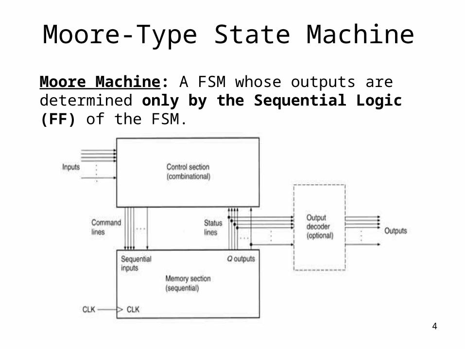
• A basic Finite State Machine (FSM) has a memory section that holds the present state of the machine (stored in FF) and a control section that controls the next state of the machine (by clocks, inputs, and present state).
4
Moore Machine: A FSM whose outputs are determined only by the Sequential Logic (FF) of the FSM.
Moore-Type State Machine

5
Mealy-Type State MachineMealy Machine: An FSM whose outputs are determined by both the sequential logic and combinational logic of the FSM

6
Classical Design Approach(Moore-Type)
• Define the actual problem.• Draw a state diagram (bubble) to implement the
problem.• Make a state table. Define all present states and inputs
in a binary sequence. Then define the next states and outputs from the state diagram.
• Use FF excitation tables to determine in what states the FF inputs must be to cause a present state to next state transition.
• Find the output values for each present state/input combination.
• Simplify Boolean logic for each FF input and output equations and design logic.

7
Moore State Machine Example
1. Define the problem: Design a counter whose output progress is a 4-bit Gray code sequence. A Gray Code is a binary code that progresses such that only one bit changes between two successive codes.

How to build a 4-bit Gray Code Table
8
3-bit Gray code0 0 00 0 10 1 10 1 01 1 01 1 11 0 11 0 0
4-bit Gray code0 0 0 00 0 0 10 0 1 10 0 1 00 1 1 00 1 1 10 1 0 10 1 0 01 1 0 01 1 0 11 1 1 11 1 1 01 0 1 01 0 1 11 0 0 11 0 0 0
2-bit Gray code0 00 11 11 0

4-bit Gray Code Table
9
4-bit Gray Code Sequence
Q3 Q2 Q1 Q00 0 0 00 0 0 10 0 1 10 0 1 00 1 1 00 1 1 10 1 0 10 1 0 01 1 0 01 1 0 11 1 1 11 1 1 01 0 1 01 0 1 11 0 0 11 0 0 0

10
State Machine Example
2. Draw a State Diagram

11
State Machine Example3. Make a State Table

12
State Machine Example
4. Use Flip-flop excitation tables to determine at what state the flip-flop synchronous input must be to make the circuit go from each state to its next state.• This is not necessary if we use “D flip-flops”,
since output Q follows input D. The D inputs are the same as next state outputs.
• For JK or T flip-flops, we would follow the same procedure as for a synchronous counters as outlined in Chapter 9

13
State Machine Example5. Simply the Boolean expression for each synchronous input

14
State Machine Example6. Draw the logic circuit for the state machine

15
FSM with Control Inputs(Mealy-Type)
• Same design approach used for FSM such as counters.
• Uses the control inputs and clock to control the sequencing from state to state.
• Inputs can also cause output changes not just FF outputs.

16
FSM with Control Inputs

17
SM Diagram Notation
• Bubbles contain the state name and value (State Name/Value), such as Start/0.• Transitions between states are designated with
arrows from one bubble to another.• Each transition has an ordered Input/Output, such as
in1/out1, out2.

18
SM Diagram Notation
• For example, if SM is at State = Start and if in1 = 0,
it then transitions to State = Continue and out1 = 1, out2 = 0.
• The arrow is drawn from start bubble to continue bubble.
• On the arrow the value 0/10 is given to represent the in1/out1,out2.

19
Analyzing the State Diagram• There are two sates called start and continue.• The machine begins in the start state waits for a Low in1. As long
as in1 is High, the machine waits and out1 and out2 are both Low.• When in1 goes Low, the machine makes a transition to continue in
one clock pulse. Output out1 goes High.• On the next clock pulse, the machine goes back to start. Output
out2 goes High and out1 goes back Low.
• If in1 is High, the machine waits for a new Low on in1. Both outs
are Low again. If in1 goes Low. The cycle repeats.

SM Design
20
Present State Input Next State Sync Inputs Outputs
Q in1 Q J K out1 out2
0 1 0 0 X 0 0
Transition JK0 1 0X0 1 1X1 0 X11 0 X0
Transition JK0 1 0X0 1 1X1 0 X11 0 X0
0
1

SM Design
21
Present State Input Next State Sync Inputs Outputs
Q in1 Q J K out1 out2
0 1 0 0 X 0 0
0 0 1 1 X 1 0
Transition JK0 1 0X0 1 1X1 0 X11 0 X0
Transition JK0 1 0X0 1 1X1 0 X11 0 X0
0
1

SM Design
22
Present State Input Next State Sync Inputs Outputs
Q in1 Q J K out1 out2
0 1 0 0 X 0 0
0 0 1 1 X 1 0
1 0 0 X 1 0 1
Transition JK0 1 0X0 1 1X1 0 X11 0 X0
Transition JK0 1 0X0 1 1X1 0 X11 0 X0
0
1

SM Design
23
Transition JK0 1 0X0 1 1X1 0 X11 0 X0
Transition JK0 1 0X0 1 1X1 0 X11 0 X0
0
1
Present State Input Next State Sync Inputs Outputs
Q in1 Q J K out1 out2
0 1 0 0 X 0 0
0 0 1 1 X 1 0
1 0 0 X 1 0 1
1 1 0 X 1 0 1

SM Design
24
Present State Input Next State Sync Inputs Outputs
Q In1 Q J K out1 out2
0 1 0 0 X 0 0
0 0 1 1 X 1 0
1 0 0 X 1 0 1
1 1 0 X 1 0 1
Out1 = Q’ in1’
Q in10 1
0 1 01 0 0
Out2 = Q
Q in10 1
0 0 01 1 1
Q in10 1
0 1 01 X X
J= in1’ K = 1
Q in10 1
0 X X1 1 1
J = in1’K = 1out1 = Q’in1’out2 = Q

SM Design
25
J = in1’K = 1out1 = Q’in1’out2 = Q

26
Unused States
• Some modulus counters, such as MOD-10, have states that are not used in the counter sequence.
• The MOD-10 Counter would have 6 unused states (1010, 1011….1111) based on 4-bits.

27
Unused States
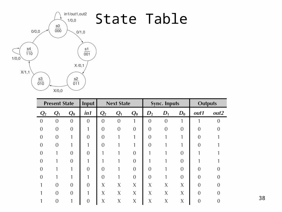
• An FSM can also have unused states, such as an SM, with only 5 bubbles in the state diagram (5-states). This FSM still requires 3 bits to represent these states so there will be 3 unused states.
• These unused states can be treated as don’t cares (X) or assigned to a specific initial state.

28
Unused States

State Diagram
29

State Table
30

State Table
31

State Table
32

State Table
33

State Table
34

State Table
35

State Table
36

State Table
37
State Table
38

State Table
39

State Table
40

State Table
41

State Table
42

State Table
43

K-Maps
44

Simplified Equations
45

46
Circuit