engineering design and technology series - solidworks · solidworks 2011, solidworks enterprise...
TRANSCRIPT

Engineering Designand Technology Series
SAE® Design and Analysis Project with SolidWorks® Software
Put Picture Here
Dassault Systémes SolidWorks
Outside the U.S.: +1-978-371-5011Fax: +1-978-371-7303
Email: [email protected]: http://www.solidworks.com/education

© 1995-2010, Dassault Systèmes SolidWorks Corporation, a Dassault Systèmes S.A. company, 300 Baker Avenue, Concord, Mass. 01742 USA. All Rights Reserved.The information and the software discussed in this document are subject to change without notice and are not commitments by Dassault Systèmes SolidWorks Corporation (DS SolidWorks).No material may be reproduced or transmitted in any form or by any means, electronically or manually, for any purpose without the express written permission of DS SolidWorks.The software discussed in this document is furnished under a license and may be used or copied only in accordance with the terms of the license. All warranties given by DS SolidWorks as to the software and documentation are set forth in the license agreement, and nothing stated in, or implied by, this document or its contents shall be considered or deemed a modification or amendment of any terms, including warranties, in the license agreement.
Patent NoticesSolidWorks® 3D mechanical CAD software is protected by U.S. Patents 5,815,154; 6,219,049; 6,219,055; 6,611,725; 6,844,877; 6,898,560; 6,906,712; 7,079,990; 7,477,262; 7,558,705; 7,571,079; 7,590,497; 7,643,027; 7,672,822; 7,688,318; 7,694,238; 7,853,940; and foreign patents, (e.g., EP 1,116,190 and JP 3,517,643).eDrawings® software is protected by U.S. Patent 7,184,044; U.S. Patent 7,502,027; and Canadian Patent 2,318,706.U.S. and foreign patents pending.
Trademarks and Product Names for SolidWorks Products and ServicesSolidWorks, 3D PartStream.NET, 3D ContentCentral, eDrawings, and the eDrawings logo are registered trademarks and FeatureManager is a jointly owned registered trademark of DS SolidWorks.CircuitWorks, Feature Palette, FloXpress, PhotoWorks, TolAnalyst, and XchangeWorks are trademarks of DS SolidWorks.FeatureWorks is a registered trademark of Geometric Software Solutions Ltd.SolidWorks 2011, SolidWorks Enterprise PDM, SolidWorks Simulation, SolidWorks Flow Simulation, and eDrawings Professional are product names of DS SolidWorks.Other brand or product names are trademarks or registered trademarks of their respective holders.
Document Number: PME1119-ENG
COMMERCIAL COMPUTER SOFTWARE - PROPRIETARYU.S. Government Restricted Rights. Use, duplication, or disclosure by the government is subject to restrictions as set forth in FAR 52.227-19 (Commercial Computer Software - Restricted Rights), DFARS 227.7202 (Commercial Computer Software and Commercial Computer Software Documentation), and in the license agreement, as applicable.Contractor/Manufacturer:Dassault Systèmes SolidWorks Corporation, 300 Baker Avenue, Concord, Massachusetts 01742 USA
Copyright Notices for SolidWorks Standard, Premium, Professional, and Education ProductsPortions of this software © 1986-2010 Siemens Product Lifecycle Management Software Inc. All rights reserved.Portions of this software © 1986-2010 Siemens Industry Software Limited. All rights reserved.Portions of this software © 1998-2010 Geometric Ltd.Portions of this software © 1996-2010 Microsoft Corporation. All rights reserved. Portions of this software incorporate PhysX™ by NVIDIA 2006-2010.Portions of this software © 2001 - 2010 Luxology, Inc. All rights reserved, Patents Pending.Portions of this software © 2007 - 2010 DriveWorks Ltd.Copyright 1984-2010 Adobe Systems Inc. and its licensors. All rights reserved. Protected by U.S. Patents 5,929,866; 5,943,063; 6,289,364; 6,563,502; 6,639,593; 6,754,382; Patents Pending.Adobe, the Adobe logo, Acrobat, the Adobe PDF logo, Distiller and Reader are registered trademarks or trademarks of Adobe Systems Inc. in the U.S. and other countries. For more copyright information, in SolidWorks see Help > About SolidWorks.
Copyright Notices for SolidWorks Simulation ProductsPortions of this software © 2008 Solversoft Corporation.PCGLSS © 1992-2007 Computational Applications and System Integration, Inc. All rights reserved.
Copyright Notices for Enterprise PDM ProductOutside In® Viewer Technology, © Copyright 1992-2010, Oracle© Copyright 1995-2010, Oracle. All rights reserved.Portions of this software © 1996-2010 Microsoft Corporation. All rights reserved.
Copyright Notices for eDrawings ProductsPortions of this software © 2000-2010 Tech Soft 3D.Portions of this software © 1995-1998 Jean-Loup Gailly and Mark Adler.Portions of this software © 1998-2001 3Dconnexion.Portions of this software © 1998-2010 Open Design Alliance. All rights reserved.Portions of this software © 1995-2009 Spatial Corporation.This software is based in part on the work of the Independent JPEG Group.

SolidWorksEngineering Design and Technology Series
Lesson 2Using Assemblies
When you complete this lesson, you will be able to:Understand the difference between edit assembly and edit part modes;Create a virtual, in-context part;Open a part from the assembly; Create a new instance from an existing instance;Set the materials in a part; Use pack and go to manage the files.
5

SolidWorks Using AssembliesEngineering Design and Technology Series
Creating Parts In-Context A thorough knowledge of how to work with assemblies is critical to success with SolidWorks. In this example, you will create a virtual part and use in-context techniques to mode a brake pad using geometry from both the Rotor - Cast Iron and Brake Caliper components. The component will copied to create a second instance and it will be mated into the assembly.
Opening an Assembly with Quick ViewClicking the Quick view / Selective open when you open an assembly allows you to view only the components that you want to view.
1 Open Brake&Wheel. Click File, Open and select the assembly Brake&Wheel from the Lesson 2\Brake&Wheel folder. Click Quick view / Selective open and click Open.
6

SolidWorks Using AssembliesEngineering Design and Technology Series
Hiding and Showing ComponentsComponents can be hidden or shown at any time to create an uncluttered display and make working on the assembly faster. In addition, components that are hidden before opening the assembly are not loaded into memory, further decreasing the load on the machine.
Tip: The Quick view / Selective open settings are stored in a Display State.
There are many ways to hide and show components. Here are a few useful methods and where they are best used.
2 Orientation. The assembly open in an Isometric orientation. Click in the graphics area and press Shift+Arrow Up to change the view orientation.
3 Hide others. Right-click the Rotor - Cast Iron and select Hide Others.
Hiding Components Showing Components
Many Components
Hide Others- Hides all visible components but the selected component(s).
Show Hidden Components- Shows all the hidden components for selection.
Single or Few Components
Hide/Show Components- Hides the selected visible components.
Hide/Show Components- Shows the selected hidden components.
7
SolidWorks Using AssembliesEngineering Design and Technology Series
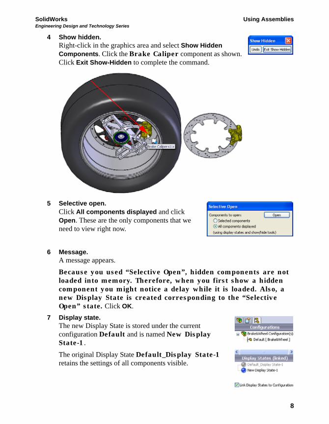
4 Show hidden. Right-click in the graphics area and select Show Hidden Components. Click the Brake Caliper component as shown. Click Exit Show-Hidden to complete the command.
5 Selective open. Click All components displayed and click Open. These are the only components that we need to view right now.
6 Message. A message appears. Because you used “Selective Open”, hidden components are not loaded into memory. Therefore, when you first show a hidden component you might notice a delay while it is loaded. Also, a new Display State is created corresponding to the “Selective Open” state. Click OK.
7 Display state. The new Display State is stored under the current configuration Default and is named New Display State-1. The original Display State Default_Display State-1 retains the settings of all components visible.
8

SolidWorks Using AssembliesEngineering Design and Technology Series
8 Save.Click File, Save to save the assembly and parts.
9 Orientation changes. Press the Spacebar and double-click the orientation *Isometric from the dialog. Middle (wheel)+click and drag the edge of the Rotor - Cast Iron as shown to rotate the geometry.
10 Zoom. Click the Brake Caliper component in the FeatureManager design tree and click Zoom to Selection .
9

SolidWorks Using AssembliesEngineering Design and Technology Series
The Assembly FeatureManager design treeThe assembly is comprised of components and mates. The components can be either part components or assembly components (sub-assemblies). The assembly FeatureManager design tree shows an accurate snapshot of the assembly using icons and text to describe the current settings.
11 AssemblyXpert. Click Tools, AssemblyXpert. The dialog lists the number of parts, unique parts, sub-assemblies and unique sub-assemblies among other things.
Click OK.
Component
Hidden Sub-assemblyComponent
Instance
Mate
Part Component
Hidden
MatesFolder
PartComponent
Sub-assemblyComponent
10

SolidWorks Using AssembliesEngineering Design and Technology Series
Working In-ContextWorking in-context means editing a component (part or assembly) while in the context of the assembly. The mode is toggled between Edit Assembly and Edit Part.
Edit Assembly Mode vs. Edit Part ModeWhen an assembly is opened, it opens in the default Edit Assembly mode. To create or edit a component part in-context, Edit Part is used. You can toggle back and forth between the modes using Edit Component .
Tip: Colors are used to indicate which mode is currently active. See “Why do the Colors Change?” on page 14 for more information.
Below is a breakdown of some common actions that are typically performed in each mode:
Edit Assembly Mode Edit Part Mode
Adding new components Creating new sketches
Inserting mates Creating sketch geometry
Moving components Creating bosses or cut features
Edit Assembly Edit Part
11

SolidWorks Using AssembliesEngineering Design and Technology Series
In-Context Parts and Virtual Parts In-Context Parts are parts that are created or edited in the context of the assembly. In-context part names appear in the FeatureManager design tree appended with an arrow (In-Context->). Virtual Parts are in-context parts that are saved within the assembly rather than as separate part files. Parts can be both in-context and virtual. Virtual part names appear in the FeatureManager design tree in square brackets [Virtual_Part^Test].
Why use In-Context and Virtual Parts?
In-Context parts reference other parts in the assembly and change automatically when the references change. Virtual Parts are more flexible because they can be renamed, deleted or saved as external (part) files at any time.
Tip: If there are no references, do not create the part in-context.
Setup for Using Edit Part There are settings under system options that can be used to determine how assemblies and virtual parts behave in Edit Part mode.
12 Virtual part setting. Click Tools, Options, System Options, Assemblies and clear Save new components to external files. Do not click OK yet.
13 In-context appearance setting. Click Display/Selection and select Opaque Assembly from the pulldown menu under Assembly transparency for in context edit. Do not click OK yet.
14 In-context part setting. Click Colors and click Use specified color when editing parts in assemblies. That color is listed under the Assembly, Edit Part setting. Click OK.
12

SolidWorks Using AssembliesEngineering Design and Technology Series
Creating a New Part Creating a in-context new part requires a few selections including a planar face or plane for use as a sketch plane. The selected face or plane will establish the orientation and position of the Front plane of the new virtual part. This in turn defines the orientations of the Top and Right planes.
15 New part. Click Insert, Component, New Part and select the face of the Brake Caliper as shown.
13

SolidWorks Using AssembliesEngineering Design and Technology Series
Edit Part Mode Edit Part Mode is the opposite toggle of Edit Assembly Mode and allows the use of sketch and feature tools within the assembly. It is triggered by adding a new part component or editing an existing part in the assembly.
Why do the Colors Change?Due to the settings made (“Setup for Using Edit Part” on page 12), the appearance of all the parts remains opaque. The part being edited will appear in the Assembly, Edit Part color and all others appear in the Assembly, Non-Edit Parts color.
Controlling the DisplayThe display includes the visibility and colors of the components in the assembly. Controlling the display is the first step in managing the assembly itself, and the Display Pane is one of the best tools.
Display Pane
The Display Pane is a portion of the FeatureManager design tree that has visual controls and is usually hidden. The columns show the current state of Hide/Show, Display Mode, Appearance and Transparency and allow you to change them. The options are described below.
Hide/Show - Toggles between Hide Component and Show Component. Display Mode - Sets the display to Wireframe, Hidden Lines Visible, Hidden Lines Removed, Shaded With Edges, Shaded, or Default Display. Appearance - Sets the appearance of the component. The lower triangle represents the part appearance while the upper triangle represents the component (assembly level) appearance. Transparency - Toggles Transparency on and off.
Note: The display pane works independently of the mode.
Hid
e/Sh
owD
ispl
ay M
ode
App
eara
nces
Tran
spar
ency
14

SolidWorks Using AssembliesEngineering Design and Technology Series
16 Display pane. Click Show Display Pane to expand the display plane and change the appearance of components. Expand the Brake Rotor Assembly folder. Click the Rotor - Cast Iron component in the Hide/Show column as shown to hide it.
Click Hide Display Pane to close the display pane.
15

SolidWorks Using AssembliesEngineering Design and Technology Series
17 Convert entities. Click Convert Entities and select the face and click twice.
Tip: If you see small green icons on the geometry of the sketch, you are seeing sketch relations. Click View, Sketch Relations to shut off their display.
18 Delete. Delete three entities to open the end of the sketch.
Note: There is one large arc and two small ones connected to it. Only one small arc is shown here.
16

SolidWorks Using AssembliesEngineering Design and Technology Series
19 Convert edge. Click Show Display Pane and show the Rotor - Cast Iron component. Click Convert Entities and select the edge of the Rotor - Cast Iron component. Click twice.
20 Sketch fillets. Click Tools, Sketch Tools, Fillet , set the Fillet Radius to 2.5mm, and select the first set of geometry by selecting the geometry inside of where they would intersect.
Repeat the selections for the similar geometry on the opposite side. Click twice.
17

SolidWorks Using AssembliesEngineering Design and Technology Series
21 View normal to. Click View Normal To and zoom in as shown.
22 Delete. Box select from upper left to lower right as shown to select the three entities. Delete the three selected entities.
23 Drag endpoints. Drag the endpoint of the vertical line outside the geometry as shown. Repeat for the other vertical line and stop where the endpoints are horizontal.
18

SolidWorks Using AssembliesEngineering Design and Technology Series
24 Tangent Arc. Click Tools, Sketch Entities, Tangent Arc and create the arc between the two endpoints as shown.
25 Drag and drop. Drag the centerpoint of the arc to the edge of the circular edge. Drop it on the centerpoint that appears.
26 Previous view. Click Previous View to go back to previous views and zoom states. Return to the zoomed isometric view.
19

SolidWorks Using AssembliesEngineering Design and Technology Series
27 Extrude. Click Extrude and set the Depth to 3mm. Click .
Understanding the Color Coding The part turns blue when the extrusion is completed. The reason was explained earlier (“Why do the Colors Change?” on page 14) but until there is a solid body, it is difficult to notice. This is the Assembly, Edit Part color and it appears in both the graphics and in the FeatureManager design tree.
20

SolidWorks Using AssembliesEngineering Design and Technology Series
28 New sketch. Select the face and click Sketch .
29 Convert entities. Select the edge and click Convert Entities as shown. Click .
21

SolidWorks Using AssembliesEngineering Design and Technology Series
30 Offset entities. Hide the Rotor - Cast Iron component. Click Offset Entities and set the Offset Distance to 2mm. Select the edge, click Reverse and click . Repeat the procedure for the opposite side.
31 Convert. Show the Rotor - Cast Iron component. Select the edge as shown and click Convert Entities . Click .
22

SolidWorks Using AssembliesEngineering Design and Technology Series
32 Drag. Drag the open endpoints out beyond the converted edge.
33 Trim. Click Trim Entities , Power trim . Click+Drag across the sections of geometry using the paths shown to trim away excess geometry.
23

SolidWorks Using AssembliesEngineering Design and Technology Series
34 Sketch fillets. Add sketch fillets Radius 1mm in four places as shown.
Tip: If corners are trimmed to a single endpoint, select the endpoint to add the fillet.
Extrusions In-Context Extrusions can also be created in-context when external generator is referenced. In this example, the depth of an extrusion is measured as an offset from an existing face.
35 Extrude. Click Extrude and set the End Condition to Offset from Surface. Set the Offset Distance to 1.5mm. Click in Face/Plane field.
24

SolidWorks Using AssembliesEngineering Design and Technology Series
36 Select other. Right-click the face as shown and select Select Other. Click the top selection, Face@[Brake Rotor Assembly<1>/Rotor - Cast Iron<1>].
Tip: The top selection at the cursor is not listed. Why? It is assumed that if you wanted to select that face you would have selected it directly.
37 Offset distance. Check the direction and click .
25

SolidWorks Using AssembliesEngineering Design and Technology Series
Edit Assembly ModeEdit Assembly Mode is the opposite toggle of Edit Part Mode and is the default state of the assembly where you can add components and mates. It is triggered by exiting the editing of a part in the assembly or opening of an assembly file.
1 Edit assembly.
Click Edit Component or the confirmation corner to edit the assembly.
This returns you to edit assembly mode and all the colors return to their original settings.
Working with Virtual PartsThe virtual part has been stored inside the assembly since it was created. Now that it nearly complete, we will save it externally and make it a real part.
Renaming a Virtual Part2 Rename.
Right-click the [Part1^Brake&Wheel] component and select Rename Part. Type the name Brake Pad.
Tip: Although the part has been renamed, it remains a virtual part.
26
SolidWorks Using AssembliesEngineering Design and Technology Series
Saving a Virtual Part as an External Part
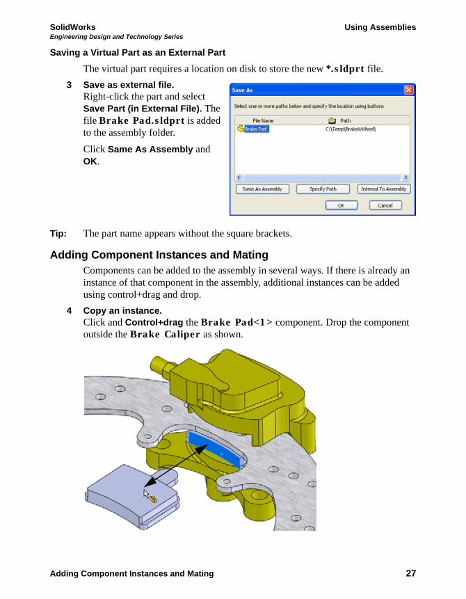
The virtual part requires a location on disk to store the new *.sldprt file. 3 Save as external file.
Right-click the part and select Save Part (in External File). The file Brake Pad.sldprt is added to the assembly folder. Click Same As Assembly and OK.
Tip: The part name appears without the square brackets.
Adding Component Instances and MatingComponents can be added to the assembly in several ways. If there is already an instance of that component in the assembly, additional instances can be added using control+drag and drop.
4 Copy an instance. Click and Control+drag the Brake Pad<1> component. Drop the component outside the Brake Caliper as shown.
Adding Component Instances and Mating 27

SolidWorks Using AssembliesEngineering Design and Technology Series
5 Hide component. Click the Rotor - Cast Iron component and click Hide Components .
6 First mate. Press Shift+Up Arrow key. Click Insert, Mate and select the faces as shown.
Click Coincident and Anti-Aligned . Click .
Adding Component Instances and Mating 28

SolidWorks Using AssembliesEngineering Design and Technology Series
7 Second mate. Press the Down Arrow key. Select the faces as shown, click Coincident and click .
8 Third mate. Hide the Brake Caliper component. Select the faces as shown, click Coincident and click
.
Show the Brake Caliper component.
Adding Component Instances and Mating 29

SolidWorks Using AssembliesEngineering Design and Technology Series
Viewing the Mates of a Component
The mates used to constrain a component can be listed and viewed using View Mates. It is a useful tool in understanding how components are used in the assembly.
Note: The arrow symbol indicates a path to ground. Mates marked like this are the ones that hold the component in place.
9 View mates. Click the Brake Pad<2> and View Mates .
Click the “x” to close the dialog.
Adding Component Instances and Mating 30

SolidWorks Using AssembliesEngineering Design and Technology Series
In-Context Part Editing Any component part can be edited in the assembly whether it was created in the context of the assembly or not. Toggling back to edit part mode uses the same command; Edit Part.
10 Edit part. Click Brake Pad<1> and Edit Part .
11 New sketch. Click the face and click Insert Sketch . A new sketch has been created on the face.
12 Convert edge. Click the circular edge and click Convert Entities . Click . Exit the sketch.
Adding Component Instances and Mating 31

SolidWorks Using AssembliesEngineering Design and Technology Series
Opening a Part from an Assembly In this example, we will create a slot is to match up with the hole in the Brake Pad component. The slot will be constructed from an existing hole and makes for easier fit up.
1 Open Brake Pad. Click on the Brake Pad<2> in the FeatureManager design tree and select Open
. 2 Edit a sketch.
Right-click on Sketch3-> in the FeatureManager design tree and select Edit Sketch .
3 Construction. Click the circle and click for construction to make it dashed.
4 Slot. Click Tools, Sketch Entities, Centerpoint Straight Slot and place the cursor at the center of the circle. Drag the cursor horizontally and click to create the centerline. Drag vertically and click to create the height. Click .
Adding Component Instances and Mating 32

SolidWorks Using AssembliesEngineering Design and Technology Series
5 Relations. Click the circle and a horizontal line of the slot. Add a Tangent relation.
6 Dimension and cut. Add a 2mm dimension as shown to fully define the sketch. Create a cut using a Through All end condition.
Multi-body MaterialsIn order to have different materials in the same part there must be multiple solid bodies (multi-bodies) within that part. This part is currently made up of three features; two bosses and one cut feature. They are listed in their order of creation. There is just one solid body because by default new boss features are merged to the current body. The part will be edited to create multi-bodies.
Boss-Extrude1-> Boss-Extrude2-> Cut-Extrude1->
Adding Component Instances and Mating 33

SolidWorks Using AssembliesEngineering Design and Technology Series
Reordering FeaturesFeatures can be reordered in the Feature Manager design tree using drag and drop. The rule to remember is that you cannot reorder a child feature before the parent feature. So how can you determine the parent/child relationships?
Parent/Child Relationships
The Parent/Child tool is used to determine the parents and children of any feature. In this case it will be used to determine the limits of where a feature can be reordered.
7 Parent/child. Right-click the Cut-Extrude1 feature and select Parent/Child. The dialog tells you that the Boss-Extrude1 and Sketch4 features are the parents of the selected feature. This also means that the Boss-Extrude2 feature is not. This means that the child can be moved to a position between the boss features. Click Close.
Note: The Sketch4 feature is embedded in the Cut-Extrude1 feature.
8 Reorder. Drag the Cut-Extrude1 feature and drop it on the Boss-Extrude1 feature. This places it between the boss features.
9 Folder. Right-click the first feature Boss-Extrude1, Control+click the second feature Cut-Extrude1 and select Add to New Folder. Name the folder Backing.
Adding Component Instances and Mating 34

SolidWorks Using AssembliesEngineering Design and Technology Series
10 Edit feature. Click Boss-Extrude2 and Edit Feature . Clear Merge result and click . There are now two solid bodies named Cut-Extrude1 and Boss-Extrude2. Rename them to Plate and Pad as shown.
Tip: The default names were taken from the last feature that was applied to the body.
MaterialsMaterials can be added to the entire part or to selected solid bodies within the part. In this case we will take advantage of the multi-body format to assign different materials to each body.
11 Material for the Plate. Right-click the body Plate and select Material, Edit Material. Under Steel, select 1023 Carbon Steel Sheet (SS). Click Apply and Close.
12 Material for the pad body. Right-click the body Boss-Extrude2 and select Material. Under Other Non-metals, select Ceramic Porelain. Click Apply and Close.
Note: Custom materials and custom material libraries can be created.
Materials 35

SolidWorks Using AssembliesEngineering Design and Technology Series
13 Open assembly. Press Control+Tab and move the cursor to the assembly.
This message appears: Models contained within the assembly have changed. Would you like to rebuild the assembly now? Click Yes.
14 Edit assembly. Click Edit Component . Hide the Brake Caliper and Rotor - Cast Iron components.
15 Display state. Select the original Display State Default_Display State-1 to have all the components visible.
Materials 36

SolidWorks Using AssembliesEngineering Design and Technology Series
Pack and GoPack and Go is utility that can be used to copy all files used by the assembly into a new folder or zip file, consolidating the file set into one location.
Work FlowThe work flow using Pack and Go creates multiple backups, using the last backup to start the next work session.
Creating a Zip File
Creating a zip file is a good way to consolidate the files and generate a backup in one step. The zip file can be used to start the next session and then be stored away.
Zip
NewFolder
File
Pack and Go 37

SolidWorks Using AssembliesEngineering Design and Technology Series
1 Pack and go. Click File, Pack and Go and click Save to Zip file. Using Browse, set the location to a temporary folder, name the file Backup_1.zip and click Save.
2 Unzip.At the start of the next session, unzip the file to a new folder and begin working. More files may be added from external drives or different folders.
3 Repeat the process.At the start of the next session, unzip to a new folder and begin working. Repeat the process each time to keep all the files together.
Adding to File Names
If you want to rename the files with each new backup, the Add prefix and Add suffix options can be used. For example, the file name Brake Caliper could become Brake Caliper_2 or 2-Hub Assembly with a suffix or prefix added.
Note: Using a prefix or suffix changes the name. It is not the same as using the SolidWorks Data Management product.
Pack and Go 38

SolidWorks Using AssembliesEngineering Design and Technology Series
4 Appending the names. Use the same settings as in the previous step 1 but click Add suffix and type _1 in the box. Click Save.
Tip: Virtual parts that have not been saved as external files will appear greyed in the list with <internal to assembly> as the folder. They are stored within the assembly that was active when they were created.
5 Save and close all files.
Pack and Go 39