engine engine control - terios club italia · engine engine control efi system (3sz-ve, k3-ve) ......
TRANSCRIPT
ES
ENGINE
ENGINE CONTROL
EFI SYSTEM (3SZ-VE, K3-VE)BASIC INSPECTION . . . . . . . . . . . . . . . . . . . . . . . . . . . . . . . . . . . . . . . . . . ES-1LOCATION. . . . . . . . . . . . . . . . . . . . . . . . . . . . . . . . . . . . . . . . . . . . . . . . . . ES-2DIAGNOSTIC TROUBLE CODE CHART . . . . . . . . . . . . . . . . . . . . . . . . . . ES-3PROBLEM SYMPTOMS TABLE . . . . . . . . . . . . . . . . . . . . . . . . . . . . . . . . . ES-4HOW TO PROCEED WITH TROUBLESHOOTING . . . . . . . . . . . . . . . . . . ES-6CUSTOMER PROBLEM ANALYSIS CHECK SHEET. . . . . . . . . . . . . . . . . ES-7CHECK / CLEAR DTCs . . . . . . . . . . . . . . . . . . . . . . . . . . . . . . . . . . . . . . . . ES-8FREEZE FRAME DATA. . . . . . . . . . . . . . . . . . . . . . . . . . . . . . . . . . . . . . . . ES-10CIRCUIT DIAGRAM. . . . . . . . . . . . . . . . . . . . . . . . . . . . . . . . . . . . . . . . . . . ES-12ECU TERMINALS . . . . . . . . . . . . . . . . . . . . . . . . . . . . . . . . . . . . . . . . . . . . ES-16ECU DATA LIST / ACTIVE TEST . . . . . . . . . . . . . . . . . . . . . . . . . . . . . . . . ES-21FAIL-SAFE CHART . . . . . . . . . . . . . . . . . . . . . . . . . . . . . . . . . . . . . . . . . . . ES-27P0105/31 . . . . . . . . . . . . . . . . . . . . . . . . . . . . . . . . . . . . . . . . . . . . . . . . . . . ES-28P0110/43 . . . . . . . . . . . . . . . . . . . . . . . . . . . . . . . . . . . . . . . . . . . . . . . . . . . ES-31P0115/42 . . . . . . . . . . . . . . . . . . . . . . . . . . . . . . . . . . . . . . . . . . . . . . . . . . . ES-35P0120/41 . . . . . . . . . . . . . . . . . . . . . . . . . . . . . . . . . . . . . . . . . . . . . . . . . . . ES-38P0130/21 . . . . . . . . . . . . . . . . . . . . . . . . . . . . . . . . . . . . . . . . . . . . . . . . . . . ES-43P0135/23 . . . . . . . . . . . . . . . . . . . . . . . . . . . . . . . . . . . . . . . . . . . . . . . . . . . ES-47P0141/24 . . . . . . . . . . . . . . . . . . . . . . . . . . . . . . . . . . . . . . . . . . . . . . . . . . . ES-47P0136/22 . . . . . . . . . . . . . . . . . . . . . . . . . . . . . . . . . . . . . . . . . . . . . . . . . . . ES-50P0171/25 . . . . . . . . . . . . . . . . . . . . . . . . . . . . . . . . . . . . . . . . . . . . . . . . . . . ES-53P0172/26 . . . . . . . . . . . . . . . . . . . . . . . . . . . . . . . . . . . . . . . . . . . . . . . . . . . ES-53P0300/17 . . . . . . . . . . . . . . . . . . . . . . . . . . . . . . . . . . . . . . . . . . . . . . . . . . . ES-58P0301/17 . . . . . . . . . . . . . . . . . . . . . . . . . . . . . . . . . . . . . . . . . . . . . . . . . . . ES-58P0302/17 . . . . . . . . . . . . . . . . . . . . . . . . . . . . . . . . . . . . . . . . . . . . . . . . . . . ES-58P0303/17 . . . . . . . . . . . . . . . . . . . . . . . . . . . . . . . . . . . . . . . . . . . . . . . . . . . ES-58P0304/17 . . . . . . . . . . . . . . . . . . . . . . . . . . . . . . . . . . . . . . . . . . . . . . . . . . . ES-58P0325/18 . . . . . . . . . . . . . . . . . . . . . . . . . . . . . . . . . . . . . . . . . . . . . . . . . . . ES-63P0335/13 . . . . . . . . . . . . . . . . . . . . . . . . . . . . . . . . . . . . . . . . . . . . . . . . . . . ES-66P0340/14 . . . . . . . . . . . . . . . . . . . . . . . . . . . . . . . . . . . . . . . . . . . . . . . . . . . ES-69P0350/16 . . . . . . . . . . . . . . . . . . . . . . . . . . . . . . . . . . . . . . . . . . . . . . . . . . . ES-72P0420/27 . . . . . . . . . . . . . . . . . . . . . . . . . . . . . . . . . . . . . . . . . . . . . . . . . . . ES-75P0443/76 . . . . . . . . . . . . . . . . . . . . . . . . . . . . . . . . . . . . . . . . . . . . . . . . . . . ES-79P0500/52 . . . . . . . . . . . . . . . . . . . . . . . . . . . . . . . . . . . . . . . . . . . . . . . . . . . ES-81P0505/71 . . . . . . . . . . . . . . . . . . . . . . . . . . . . . . . . . . . . . . . . . . . . . . . . . . . ES-83P0535/44 . . . . . . . . . . . . . . . . . . . . . . . . . . . . . . . . . . . . . . . . . . . . . . . . . . . ES-87P1105/32 . . . . . . . . . . . . . . . . . . . . . . . . . . . . . . . . . . . . . . . . . . . . . . . . . . . ES-89P1300/36 . . . . . . . . . . . . . . . . . . . . . . . . . . . . . . . . . . . . . . . . . . . . . . . . . . . ES-90P1346/75 . . . . . . . . . . . . . . . . . . . . . . . . . . . . . . . . . . . . . . . . . . . . . . . . . . . ES-94P1349/73 . . . . . . . . . . . . . . . . . . . . . . . . . . . . . . . . . . . . . . . . . . . . . . . . . . . ES-95P1351/62 . . . . . . . . . . . . . . . . . . . . . . . . . . . . . . . . . . . . . . . . . . . . . . . . . . . ES-99P1510/54 . . . . . . . . . . . . . . . . . . . . . . . . . . . . . . . . . . . . . . . . . . . . . . . . . . . ES-100P1560/61 . . . . . . . . . . . . . . . . . . . . . . . . . . . . . . . . . . . . . . . . . . . . . . . . . . . ES-103P1600/83 . . . . . . . . . . . . . . . . . . . . . . . . . . . . . . . . . . . . . . . . . . . . . . . . . . . ES-105P1601/81 . . . . . . . . . . . . . . . . . . . . . . . . . . . . . . . . . . . . . . . . . . . . . . . . . . . ES-106P1656/74 . . . . . . . . . . . . . . . . . . . . . . . . . . . . . . . . . . . . . . . . . . . . . . . . . . . ES-109U0101/82 . . . . . . . . . . . . . . . . . . . . . . . . . . . . . . . . . . . . . . . . . . . . . . . . . . . ES-112U0121/86 . . . . . . . . . . . . . . . . . . . . . . . . . . . . . . . . . . . . . . . . . . . . . . . . . . . ES-112U0156/87 . . . . . . . . . . . . . . . . . . . . . . . . . . . . . . . . . . . . . . . . . . . . . . . . . . . ES-112U1000/85 . . . . . . . . . . . . . . . . . . . . . . . . . . . . . . . . . . . . . . . . . . . . . . . . . . . ES-112U1002/88 . . . . . . . . . . . . . . . . . . . . . . . . . . . . . . . . . . . . . . . . . . . . . . . . . . . ES-112FUEL PUMP CONTROL SYSTEM . . . . . . . . . . . . . . . . . . . . . . . . . . . . . . . ES-115
TO INDEX
ES
ECU POWER SOURCE SYSTEM. . . . . . . . . . . . . . . . . . . . . . . . . . . . . . . . ES-120
THROTTLE BODY ASSEMBLY (3SZ-VE)COMPONENTS . . . . . . . . . . . . . . . . . . . . . . . . . . . . . . . . . . . . . . . . . . . . . . ES-125REMOVAL . . . . . . . . . . . . . . . . . . . . . . . . . . . . . . . . . . . . . . . . . . . . . . . . . . ES-127INSTALLATION . . . . . . . . . . . . . . . . . . . . . . . . . . . . . . . . . . . . . . . . . . . . . . ES-128INSPECTION . . . . . . . . . . . . . . . . . . . . . . . . . . . . . . . . . . . . . . . . . . . . . . . . ES-129
KNOCK CONTROL SENSOR (3SZ-VE)COMPONENTS . . . . . . . . . . . . . . . . . . . . . . . . . . . . . . . . . . . . . . . . . . . . . . ES-130REMOVAL . . . . . . . . . . . . . . . . . . . . . . . . . . . . . . . . . . . . . . . . . . . . . . . . . . ES-133INSTALLATION . . . . . . . . . . . . . . . . . . . . . . . . . . . . . . . . . . . . . . . . . . . . . . ES-134INSPECTION . . . . . . . . . . . . . . . . . . . . . . . . . . . . . . . . . . . . . . . . . . . . . . . . ES-134
CAMSHAFT TIMING OIL CONTROL VALVE ASSEMBLY (3SZ-VE)COMPONENTS . . . . . . . . . . . . . . . . . . . . . . . . . . . . . . . . . . . . . . . . . . . . . . ES-135REMOVAL . . . . . . . . . . . . . . . . . . . . . . . . . . . . . . . . . . . . . . . . . . . . . . . . . . ES-136INSTALLATION . . . . . . . . . . . . . . . . . . . . . . . . . . . . . . . . . . . . . . . . . . . . . . ES-136ON-VEHICLE INSPECTION . . . . . . . . . . . . . . . . . . . . . . . . . . . . . . . . . . . . ES-136INSPECTION . . . . . . . . . . . . . . . . . . . . . . . . . . . . . . . . . . . . . . . . . . . . . . . . ES-137
ENGINE CONTROL COMPUTER (3SZ-VEÅjCOMPONENTS . . . . . . . . . . . . . . . . . . . . . . . . . . . . . . . . . . . . . . . . . . . . . . ES-138REMOVAL . . . . . . . . . . . . . . . . . . . . . . . . . . . . . . . . . . . . . . . . . . . . . . . . . . ES-139INSTALLATION . . . . . . . . . . . . . . . . . . . . . . . . . . . . . . . . . . . . . . . . . . . . . . ES-139
E.F.I. WATER TEMPERATURE (3SZ-VE)INSPECTION . . . . . . . . . . . . . . . . . . . . . . . . . . . . . . . . . . . . . . . . . . . . . . . . ES-140
E.F.I. COMPUTER RELAY (3SZ-VE)INSPECTION . . . . . . . . . . . . . . . . . . . . . . . . . . . . . . . . . . . . . . . . . . . . . . . . ES-141
THROTTLE POSITION SENSOR (3SZ-VE)INSPECTION . . . . . . . . . . . . . . . . . . . . . . . . . . . . . . . . . . . . . . . . . . . . . . . . ES-142
ENGINE CONTROL - EFI SYSTEM (3SZ-VE, K3-VE) ES–1
ES
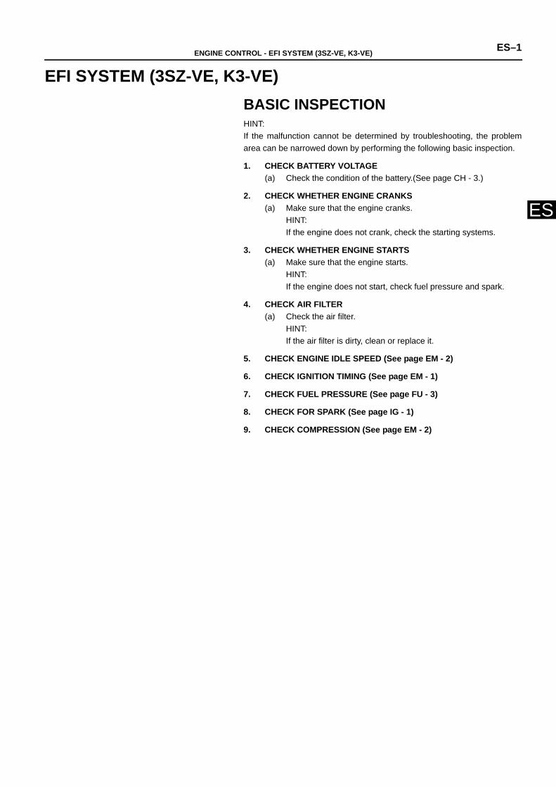
ENGINEENGINE CONTROLEFI SYSTEM (3SZ-VE, K3-VE)BASIC INSPECTIONHINT:If the malfunction cannot be determined by troubleshooting, the problemarea can be narrowed down by performing the following basic inspection.
1. CHECK BATTERY VOLTAGE(a) Check the condition of the battery.(See page CH - 3.)
2. CHECK WHETHER ENGINE CRANKS(a) Make sure that the engine cranks.
HINT:If the engine does not crank, check the starting systems.
3. CHECK WHETHER ENGINE STARTS(a) Make sure that the engine starts.
HINT:If the engine does not start, check fuel pressure and spark.
4. CHECK AIR FILTER(a) Check the air filter.
HINT:If the air filter is dirty, clean or replace it.
5. CHECK ENGINE IDLE SPEED (See page EM - 2)
6. CHECK IGNITION TIMING (See page EM - 1)
7. CHECK FUEL PRESSURE (See page FU - 3)
8. CHECK FOR SPARK (See page IG - 1)
9. CHECK COMPRESSION (See page EM - 2)
ES–2 ENGINE CONTROL - EFI SYSTEM (3SZ-VE, K3-VE)
ES
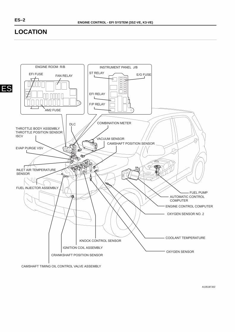
LOCATION
ENGINE ROOM R/B
EFI FUSE FAN RELAY
INSTRUMENT PANEL J/B
ST RELAY E/G FUSE
EFI RELAY
F/P RELAY
AM2 FUSE
THROTTLE BODY ASSEMBLY THROTTLE POSITION SENSOR ISCV
EVAP PURGE VSV
INLET AIR TEMPERATURE SENSOR
FUEL INJECTOR ASSEMBLY
COMBINATION METER DLC
VACUUM SENSOR
FUEL PUMP AUTOMATIC CONTROL COMPUTER
ENGINE CONTROL COMPUTER
OXYGEN SENSOR NO. 2
COOLANT TEMPERATURE
OXYGEN SENSOR
CAMSHAFT TIMING OIL CONTROL VALVE ASSEMBLY
CRANKSHAFT POSITION SENSOR
IGNITION COIL ASSEMBLY
KNOCK CONTROL SENSOR
CAMSHAFT POSITION SENSOR
A135187J02
ENGINE CONTROL - EFI SYSTEM (3SZ-VE, K3-VE) ES–3
ES
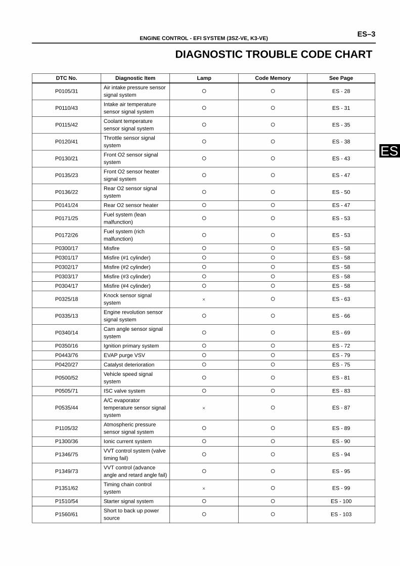
DIAGNOSTIC TROUBLE CODE CHART
DTC No. Diagnostic Item Lamp Code Memory See Page
P0105/31Air intake pressure sensor signal system
ES - 28
P0110/43Intake air temperature sensor signal system
ES - 31
P0115/42Coolant temperature sensor signal system
ES - 35
P0120/41Throttle sensor signal system
ES - 38
P0130/21Front O2 sensor signal system
ES - 43
P0135/23Front O2 sensor heater signal system
ES - 47
P0136/22Rear O2 sensor signal system
ES - 50
P0141/24 Rear O2 sensor heater ES - 47
P0171/25Fuel system (lean malfunction)
ES - 53
P0172/26Fuel system (rich malfunction)
ES - 53
P0300/17 Misfire ES - 58
P0301/17 Misfire (#1 cylinder) ES - 58
P0302/17 Misfire (#2 cylinder) ES - 58
P0303/17 Misfire (#3 cylinder) ES - 58
P0304/17 Misfire (#4 cylinder) ES - 58
P0325/18Knock sensor signal system
× ES - 63
P0335/13Engine revolution sensor signal system
ES - 66
P0340/14Cam angle sensor signal system
ES - 69
P0350/16 Ignition primary system ES - 72
P0443/76 EVAP purge VSV ES - 79
P0420/27 Catalyst deterioration ES - 75
P0500/52Vehicle speed signal system
ES - 81
P0505/71 ISC valve system ES - 83
P0535/44A/C evaporator temperature sensor signal system
× ES - 87
P1105/32Atmospheric pressure sensor signal system
ES - 89
P1300/36 Ionic current system ES - 90
P1346/75VVT control system (valve timing fail)
ES - 94
P1349/73VVT control (advance angle and retard angle fail)
ES - 95
P1351/62Timing chain control system
× ES - 99
P1510/54 Starter signal system ES - 100
P1560/61Short to back up power source
ES - 103
ES–4 ENGINE CONTROL - EFI SYSTEM (3SZ-VE, K3-VE)
ES
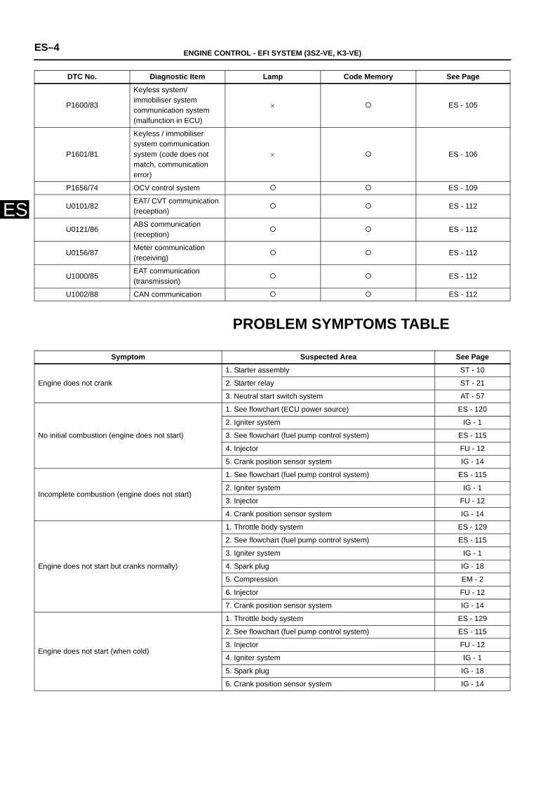
PROBLEM SYMPTOMS TABLE
P1600/83
Keyless system/ immobiliser system communication system (malfunction in ECU)
× ES - 105
P1601/81
Keyless / immobiliser system communication system (code does not match, communication error)
× ES - 106
P1656/74 OCV control system ES - 109
U0101/82EAT/ CVT communication (reception)
ES - 112
U0121/86ABS communication (reception)
ES - 112
U0156/87Meter communication (receiving)
ES - 112
U1000/85EAT communication (transmission)
ES - 112
U1002/88 CAN communication ES - 112
DTC No. Diagnostic Item Lamp Code Memory See Page
Symptom Suspected Area See Page
Engine does not crank
1. Starter assembly ST - 10
2. Starter relay ST - 21
3. Neutral start switch system AT - 57
No initial combustion (engine does not start)
1. See flowchart (ECU power source) ES - 120
2. Igniter system IG - 1
3. See flowchart (fuel pump control system) ES - 115
4. Injector FU - 12
5. Crank position sensor system IG - 14
Incomplete combustion (engine does not start)
1. See flowchart (fuel pump control system) ES - 115
2. Igniter system IG - 1
3. Injector FU - 12
4. Crank position sensor system IG - 14
Engine does not start but cranks normally)
1. Throttle body system ES - 129
2. See flowchart (fuel pump control system) ES - 115
3. Igniter system IG - 1
4. Spark plug IG - 18
5. Compression EM - 2
6. Injector FU - 12
7. Crank position sensor system IG - 14
Engine does not start (when cold)
1. Throttle body system ES - 129
2. See flowchart (fuel pump control system) ES - 115
3. Injector FU - 12
4. Igniter system IG - 1
5. Spark plug IG - 18
6. Crank position sensor system IG - 14
ENGINE CONTROL - EFI SYSTEM (3SZ-VE, K3-VE) ES–5
ES
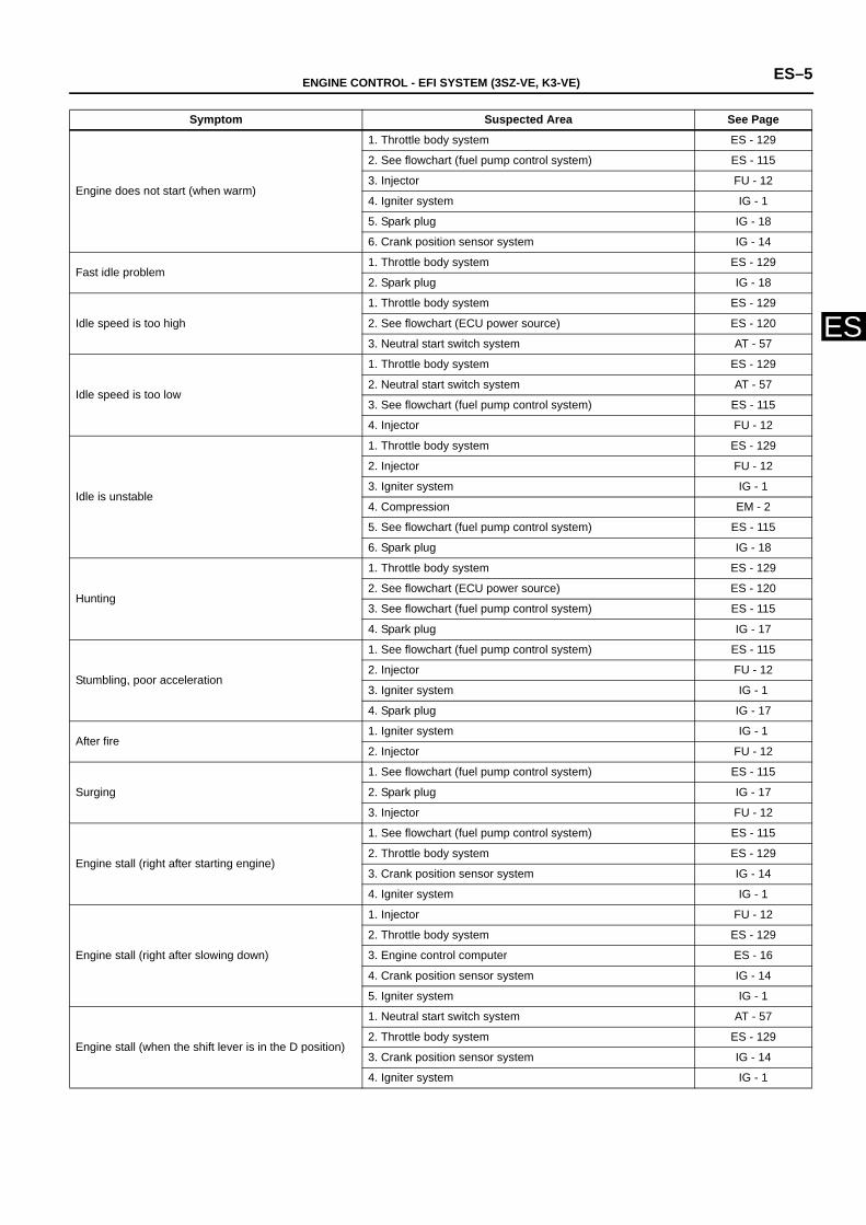
Engine does not start (when warm)
1. Throttle body system ES - 129
2. See flowchart (fuel pump control system) ES - 115
3. Injector FU - 12
4. Igniter system IG - 1
5. Spark plug IG - 18
6. Crank position sensor system IG - 14
Fast idle problem1. Throttle body system ES - 129
2. Spark plug IG - 18
Idle speed is too high
1. Throttle body system ES - 129
2. See flowchart (ECU power source) ES - 120
3. Neutral start switch system AT - 57
Idle speed is too low
1. Throttle body system ES - 129
2. Neutral start switch system AT - 57
3. See flowchart (fuel pump control system) ES - 115
4. Injector FU - 12
Idle is unstable
1. Throttle body system ES - 129
2. Injector FU - 12
3. Igniter system IG - 1
4. Compression EM - 2
5. See flowchart (fuel pump control system) ES - 115
6. Spark plug IG - 18
Hunting
1. Throttle body system ES - 129
2. See flowchart (ECU power source) ES - 120
3. See flowchart (fuel pump control system) ES - 115
4. Spark plug IG - 17
Stumbling, poor acceleration
1. See flowchart (fuel pump control system) ES - 115
2. Injector FU - 12
3. Igniter system IG - 1
4. Spark plug IG - 17
After fire 1. Igniter system IG - 1
2. Injector FU - 12
Surging
1. See flowchart (fuel pump control system) ES - 115
2. Spark plug IG - 17
3. Injector FU - 12
Engine stall (right after starting engine)
1. See flowchart (fuel pump control system) ES - 115
2. Throttle body system ES - 129
3. Crank position sensor system IG - 14
4. Igniter system IG - 1
Engine stall (right after slowing down)
1. Injector FU - 12
2. Throttle body system ES - 129
3. Engine control computer ES - 16
4. Crank position sensor system IG - 14
5. Igniter system IG - 1
Engine stall (when the shift lever is in the D position)
1. Neutral start switch system AT - 57
2. Throttle body system ES - 129
3. Crank position sensor system IG - 14
4. Igniter system IG - 1
Symptom Suspected Area See Page
ES–6 ENGINE CONTROL - EFI SYSTEM (3SZ-VE, K3-VE)
ES
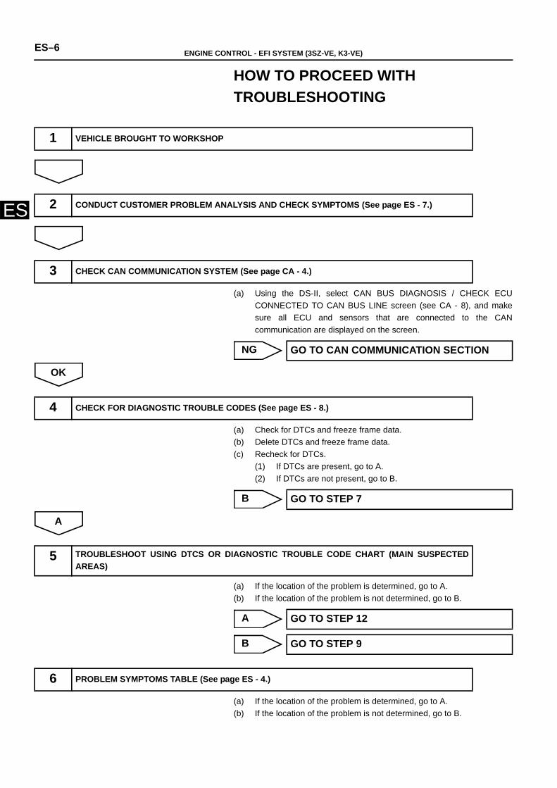
HOW TO PROCEED WITH TROUBLESHOOTING
(a) Using the DS-II, select CAN BUS DIAGNOSIS / CHECK ECUCONNECTED TO CAN BUS LINE screen (see CA - 8), and makesure all ECU and sensors that are connected to the CANcommunication are displayed on the screen.
NG
OK
(a) Check for DTCs and freeze frame data.(b) Delete DTCs and freeze frame data. (c) Recheck for DTCs.
(1) If DTCs are present, go to A.(2) If DTCs are not present, go to B.
B
A
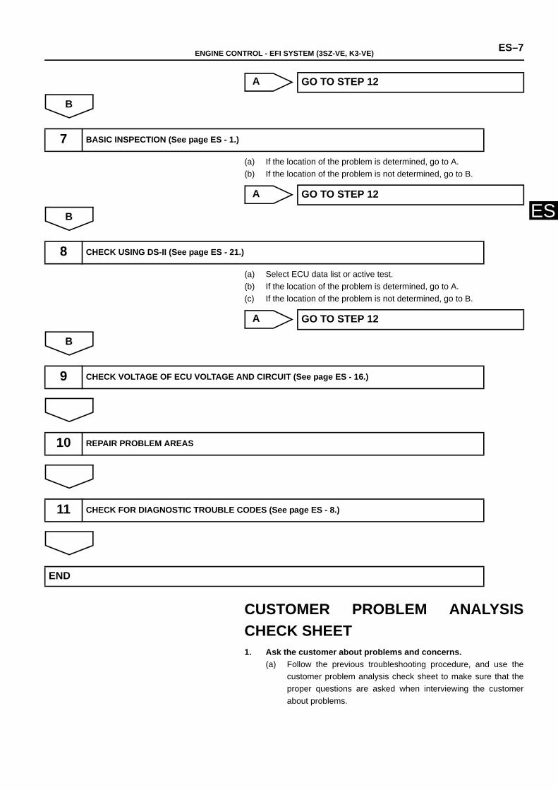
(a) If the location of the problem is determined, go to A.(b) If the location of the problem is not determined, go to B.
A
B
(a) If the location of the problem is determined, go to A.(b) If the location of the problem is not determined, go to B.
1 VEHICLE BROUGHT TO WORKSHOP
2 CONDUCT CUSTOMER PROBLEM ANALYSIS AND CHECK SYMPTOMS (See page ES - 7.)
3 CHECK CAN COMMUNICATION SYSTEM (See page CA - 4.)
GO TO CAN COMMUNICATION SECTION
4 CHECK FOR DIAGNOSTIC TROUBLE CODES (See page ES - 8.)
GO TO STEP 7
5 TROUBLESHOOT USING DTCS OR DIAGNOSTIC TROUBLE CODE CHART (MAIN SUSPECTEDAREAS)
GO TO STEP 12
GO TO STEP 9
6 PROBLEM SYMPTOMS TABLE (See page ES - 4.)
ENGINE CONTROL - EFI SYSTEM (3SZ-VE, K3-VE) ES–7
ES
A
B
(a) If the location of the problem is determined, go to A.(b) If the location of the problem is not determined, go to B.
A
B
(a) Select ECU data list or active test.(b) If the location of the problem is determined, go to A.(c) If the location of the problem is not determined, go to B.
A
B
CUSTOMER PROBLEM ANALYSISCHECK SHEET1. Ask the customer about problems and concerns.
(a) Follow the previous troubleshooting procedure, and use thecustomer problem analysis check sheet to make sure that theproper questions are asked when interviewing the customerabout problems.
GO TO STEP 12
7 BASIC INSPECTION (See page ES - 1.)
GO TO STEP 12
8 CHECK USING DS-II (See page ES - 21.)
GO TO STEP 12
9 CHECK VOLTAGE OF ECU VOLTAGE AND CIRCUIT (See page ES - 16.)
10 REPAIR PROBLEM AREAS
11 CHECK FOR DIAGNOSTIC TROUBLE CODES (See page ES - 8.)
END
ES–8 ENGINE CONTROL - EFI SYSTEM (3SZ-VE, K3-VE)
ES
CHECK / CLEAR DTCs1. PREPARE FOR INSPECTION
(a) Make sure that the throttle valve is fully closed.
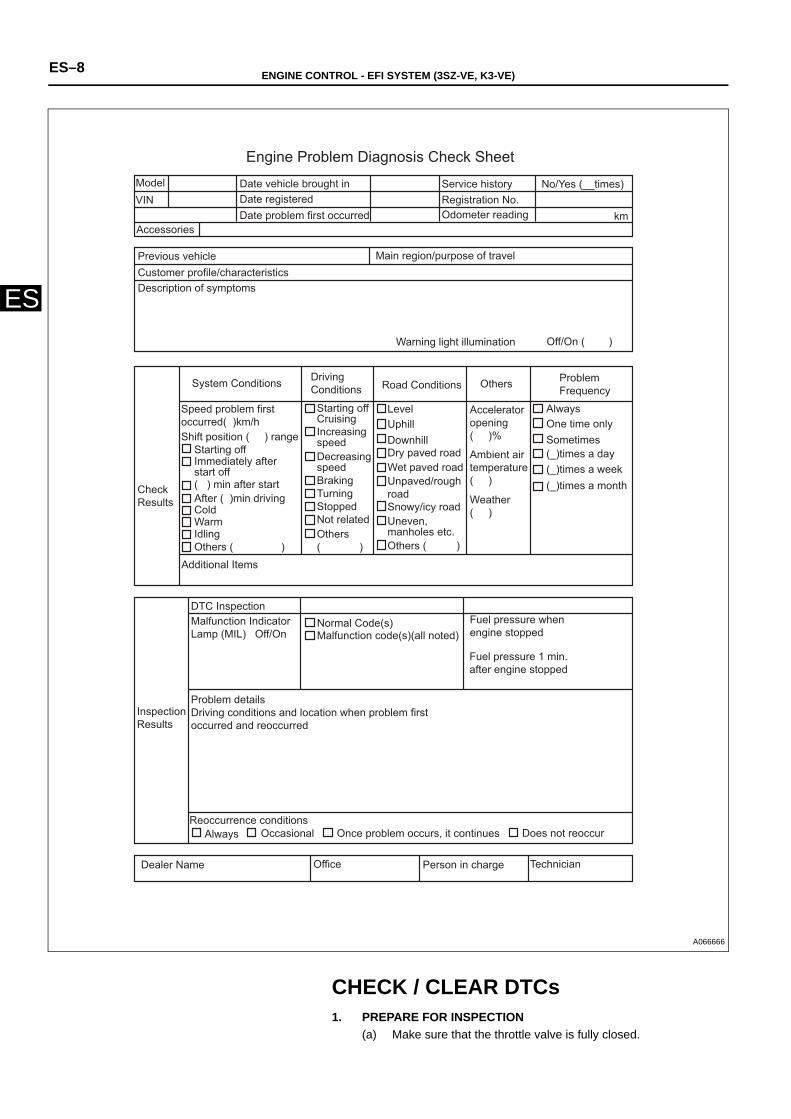
Engine Problem Diagnosis Check Sheet ModelVIN
Accessories
Date vehicle brought inDate registered Date problem first occurred
Service history No/Yes (__times)Registration No.Odometer reading km
Main region/purpose of travelPrevious vehicleCustomer profile/characteristicsDescription of symptoms
Warning light illumination Off/On ( )
System Conditions
Speed problem first occurred( )km/h Shift position ( ) range
Starting offImmediately after start off( ) min after start After ( )min drivingColdWarmIdlingOthers ( )
Check Results
Additional Items
Starting offCruising
Driving Conditions
Increasing speed Decreasing speedBraking Turning Stopped Not relatedOthers( )
Road Conditions
LevelUphill DownhillDry paved roadWet paved road
Ambient air temperature( )
Weather( )
Unpaved/rough road Snowy/icy roadUneven, manholes etc.Others ( )
Accelerator opening ( )%
Others Problem Frequency
Always One time onlySometimes(_)times a day(_)times a week(_)times a month
Fuel pressure when engine stopped
Fuel pressure 1 min. after engine stopped
Normal Code(s) Malfunction code(s)(all noted)
DTC InspectionMalfunction Indicator Lamp (MIL) Off/On
Problem details Driving conditions and location when problem first occurred and reoccurred
Inspection Results
Reoccurrence conditionsAlways Occasional Once problem occurs, it continues Does not reoccur
Dealer Name Office Person in charge Technician
A066666
ENGINE CONTROL - EFI SYSTEM (3SZ-VE, K3-VE) ES–9
ES
(b) Move the shift lever to the N or P position. (c) Turn off the air conditioner.
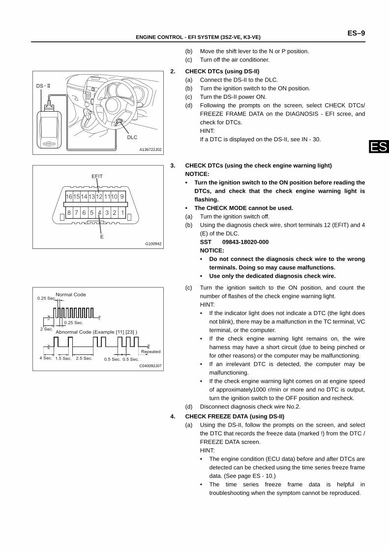
2. CHECK DTCs (using DS-II)(a) Connect the DS-II to the DLC.(b) Turn the ignition switch to the ON position.(c) Turn the DS-II power ON. (d) Following the prompts on the screen, select CHECK DTCs/
FREEZE FRAME DATA on the DIAGNOSIS - EFI scree, andcheck for DTCs. HINT:If a DTC is displayed on the DS-II, see IN - 30.
3. CHECK DTCs (using the check engine warning light)NOTICE:• Turn the ignition switch to the ON position before reading the
DTCs, and check that the check engine warning light isflashing.
• The CHECK MODE cannot be used.(a) Turn the ignition switch off.(b) Using the diagnosis check wire, short terminals 12 (EFIT) and 4
(E) of the DLC.SST 09843-18020-000 NOTICE:• Do not connect the diagnosis check wire to the wrong
terminals. Doing so may cause malfunctions. • Use only the dedicated diagnosis check wire.
(c) Turn the ignition switch to the ON position, and count thenumber of flashes of the check engine warning light. HINT:• If the indicator light does not indicate a DTC (the light does
not blink), there may be a malfunction in the TC terminal, VCterminal, or the computer.
• If the check engine warning light remains on, the wireharness may have a short circuit (due to being pinched orfor other reasons) or the computer may be malfunctioning.
• If an irrelevant DTC is detected, the computer may bemalfunctioning.
• If the check engine warning light comes on at engine speedof approximately1000 r/min or more and no DTC is output,turn the ignition switch to the OFF position and recheck.
(d) Disconnect diagnosis check wire No.2.
4. CHECK FREEZE DATA (using DS-II)(a) Using the DS-II, follow the prompts on the screen, and select
the DTC that records the freeze data (marked !) from the DTC /FREEZE DATA screen. HINT:• The engine condition (ECU data) before and after DTCs are
detected can be checked using the time series freeze framedata. (See page ES - 10.)
• The time series freeze frame data is helpful introubleshooting when the symptom cannot be reproduced.
DS
DLC
A136722J02
E
EFIT
G100942
0.25 Sec. Normal Code
2 Sec.0.25 Sec.
Abnormal Code (Example [11] [23] )
0.5 Sec. 0.5 Sec.
Repeated 4 Sec. 1.5 Sec. 2.5 Sec.
C040092J07
ES–10 ENGINE CONTROL - EFI SYSTEM (3SZ-VE, K3-VE)
ES
5. DELETE RECORDED DTCs (using DS-II)(a) Following the prompts on the screen, select the DTC / FREEZE
DATA screen and delete the DTCs.NOTICE:• If the DTCs cannot be deleted, turn the ignition switch
off, then perform the procedure again.• Until the cause of problems are clarified, do not delete
the DTCs using the DS-II.• Write the DTCs down before deleting them.
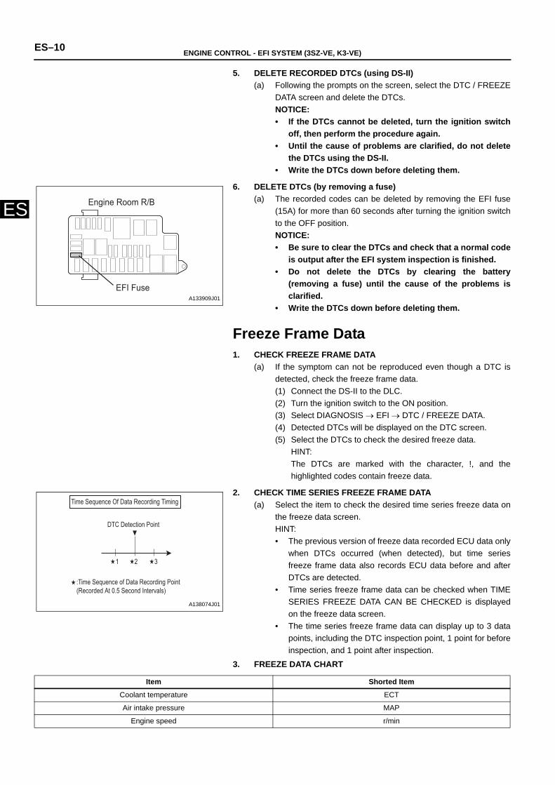
6. DELETE DTCs (by removing a fuse)(a) The recorded codes can be deleted by removing the EFI fuse
(15A) for more than 60 seconds after turning the ignition switchto the OFF position. NOTICE:• Be sure to clear the DTCs and check that a normal code
is output after the EFI system inspection is finished.• Do not delete the DTCs by clearing the battery
(removing a fuse) until the cause of the problems isclarified.
• Write the DTCs down before deleting them.
Freeze Frame Data1. CHECK FREEZE FRAME DATA
(a) If the symptom can not be reproduced even though a DTC isdetected, check the freeze frame data.(1) Connect the DS-II to the DLC.(2) Turn the ignition switch to the ON position.(3) Select DIAGNOSIS → EFI → DTC / FREEZE DATA.(4) Detected DTCs will be displayed on the DTC screen.(5) Select the DTCs to check the desired freeze data.
HINT:The DTCs are marked with the character, !, and thehighlighted codes contain freeze data.
2. CHECK TIME SERIES FREEZE FRAME DATA(a) Select the item to check the desired time series freeze data on
the freeze data screen.HINT:• The previous version of freeze data recorded ECU data only
when DTCs occurred (when detected), but time seriesfreeze frame data also records ECU data before and afterDTCs are detected.
• Time series freeze frame data can be checked when TIMESERIES FREEZE DATA CAN BE CHECKED is displayedon the freeze data screen.
• The time series freeze frame data can display up to 3 datapoints, including the DTC inspection point, 1 point for beforeinspection, and 1 point after inspection.
3. FREEZE DATA CHART
Engine Room R/B
EFI FuseA133909J01
1 2 3
Time Sequence Of Data Recording Timing
DTC Detection Point
:Time Sequence of Data Recording Point(Recorded At 0.5 Second Intervals)
A138074J01
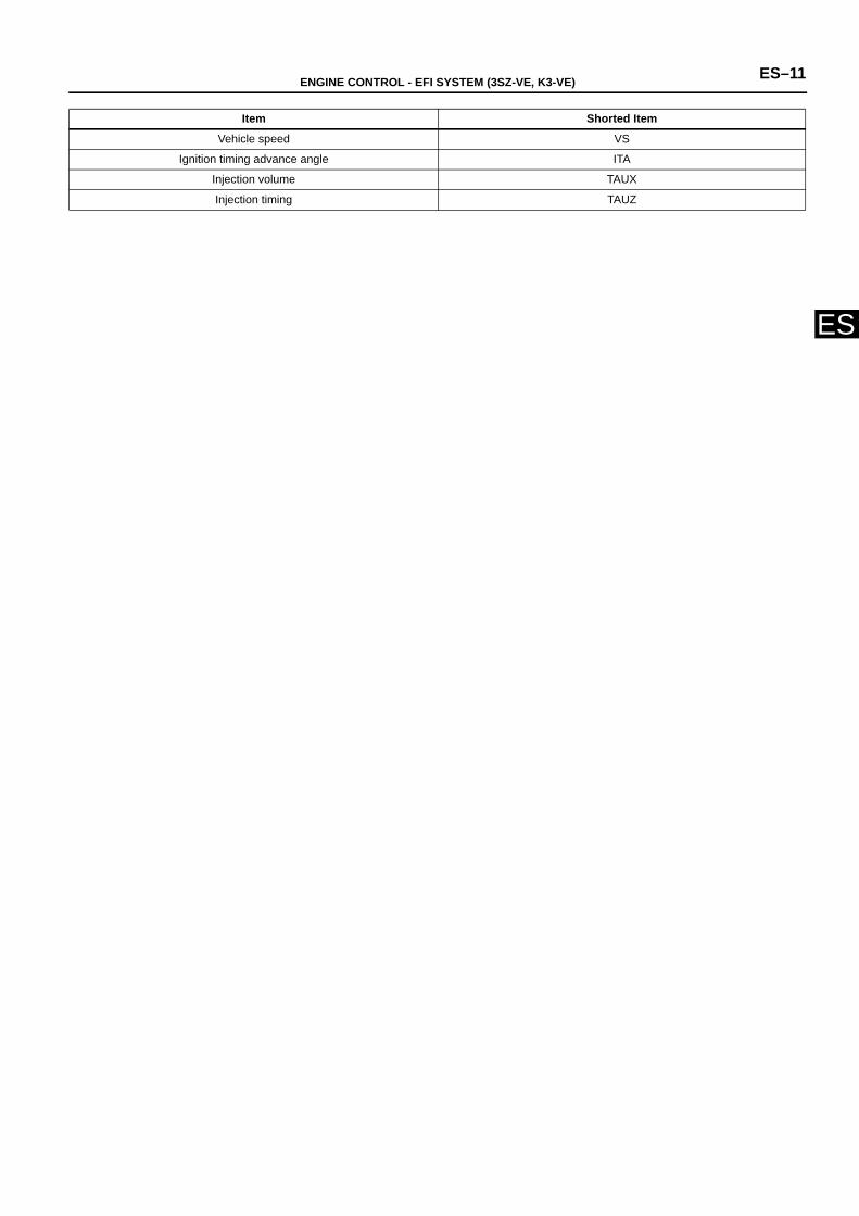
Item Shorted Item
Coolant temperature ECT
Air intake pressure MAP
Engine speed r/min
ENGINE CONTROL - EFI SYSTEM (3SZ-VE, K3-VE) ES–11
ES
Vehicle speed VS
Ignition timing advance angle ITA
Injection volume TAUX
Injection timing TAUZ
Item Shorted Item
ES–12 ENGINE CONTROL - EFI SYSTEM (3SZ-VE, K3-VE)
ES
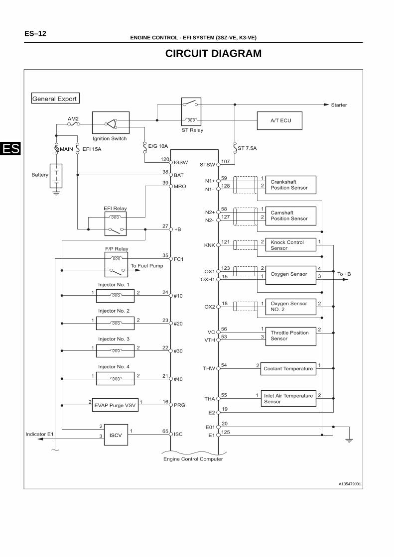
CIRCUIT DIAGRAM
Starter
EFI Relay
F/P Relay
Crankshaft Position Sensor
Camshaft Position Sensor
Knock Control Sensor
E/G
AM2
MAIN ST 7.5A
ISCV
15A 10AEFI
STSW
N1+
N1-
N2+N2-
KNK
OX1OXH1
OX2
VCVTH
THW
THA
E2
E01
E1ISC
PRG
#40
#30
#20
#10
FC1
+B
MRO
BAT
IGSW 107
59128
58127
121
123
15
18
5653
54
55
19
20
125
120
38
39
27
35
24
23
22
21
16
65
12
1
2
2 1
1
2
34
1 2
1 23
2 1
1 2
2
2
2
2
2
2
1
1
1
1
1
13
A/T ECU
Indicator E1
EVAP Purge VSV
Injector No. 4
Injector No. 3
Injector No. 2
Injector No. 1
Inlet Air Temperature Sensor
Coolant Temperature
Throttle Position Sensor
Oxygen Sensor NO. 2
Oxygen Sensor To +B
Engine Control Computer
To Fuel Pump
General Export
Ignition Switch
Battery
ST Relay
A135479J01
ENGINE CONTROL - EFI SYSTEM (3SZ-VE, K3-VE) ES–13
ES
STP 10A
A/T ECU
DLC
OCV
STP
DEF
OCV+
OCV-
VCPMPIM
E2PM
ACEV
E21
EPS
SIO2
FPOF
REV
EFIT
BLWACSW
ALT
HCANLCAN
CANHCANLATNE
FAN1
W
IG1
IG2
IG3
IG4
43
11
26
25
5752
122
45
116
12
117
44
4245
118
113
63
62
61
60
13
37
135
9
8
764
1
1
132
9
2
2
3
3
3
3
1
1
1
1
4
4
4
4
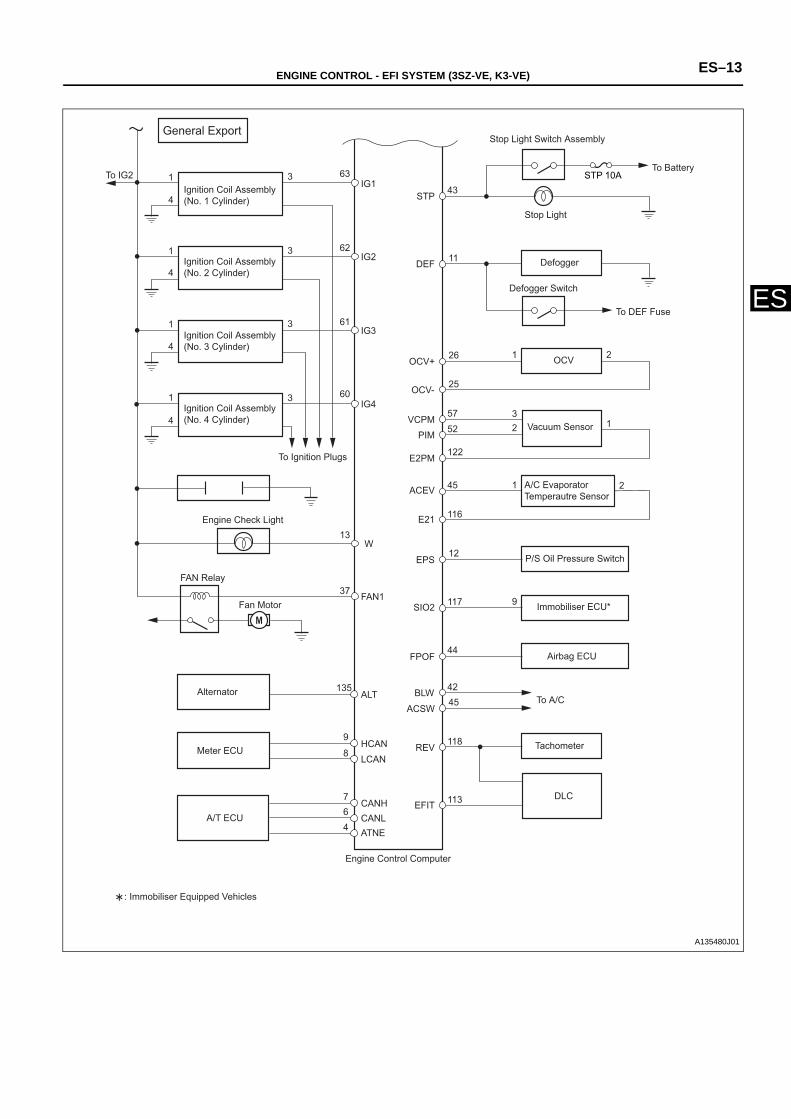
General Export
To IG2 Ignition Coil Assembly (No. 1 Cylinder)
Ignition Coil Assembly (No. 2 Cylinder)
Ignition Coil Assembly (No. 3 Cylinder)
Ignition Coil Assembly (No. 4 Cylinder)
To Ignition Plugs
Engine Check Light
FAN Relay
Fan Motor
Alternator
Meter ECU Tachometer
Airbag ECU
Immobiliser ECU*
P/S Oil Pressure Switch
A/C Evaporator Temperautre Sensor
To A/C
Vacuum Sensor
Engine Control Computer
Defogger Switch
Defogger
To DEF Fuse
Stop Light
To Battery
Stop Light Switch Assembly
: Immobiliser Equipped Vehicles
A135480J01
ES–14 ENGINE CONTROL - EFI SYSTEM (3SZ-VE, K3-VE)
ES
EFI Relay
Throttle Position Sensor
To B
To B
Knock Control Sensor
Camshaft Position Sensor
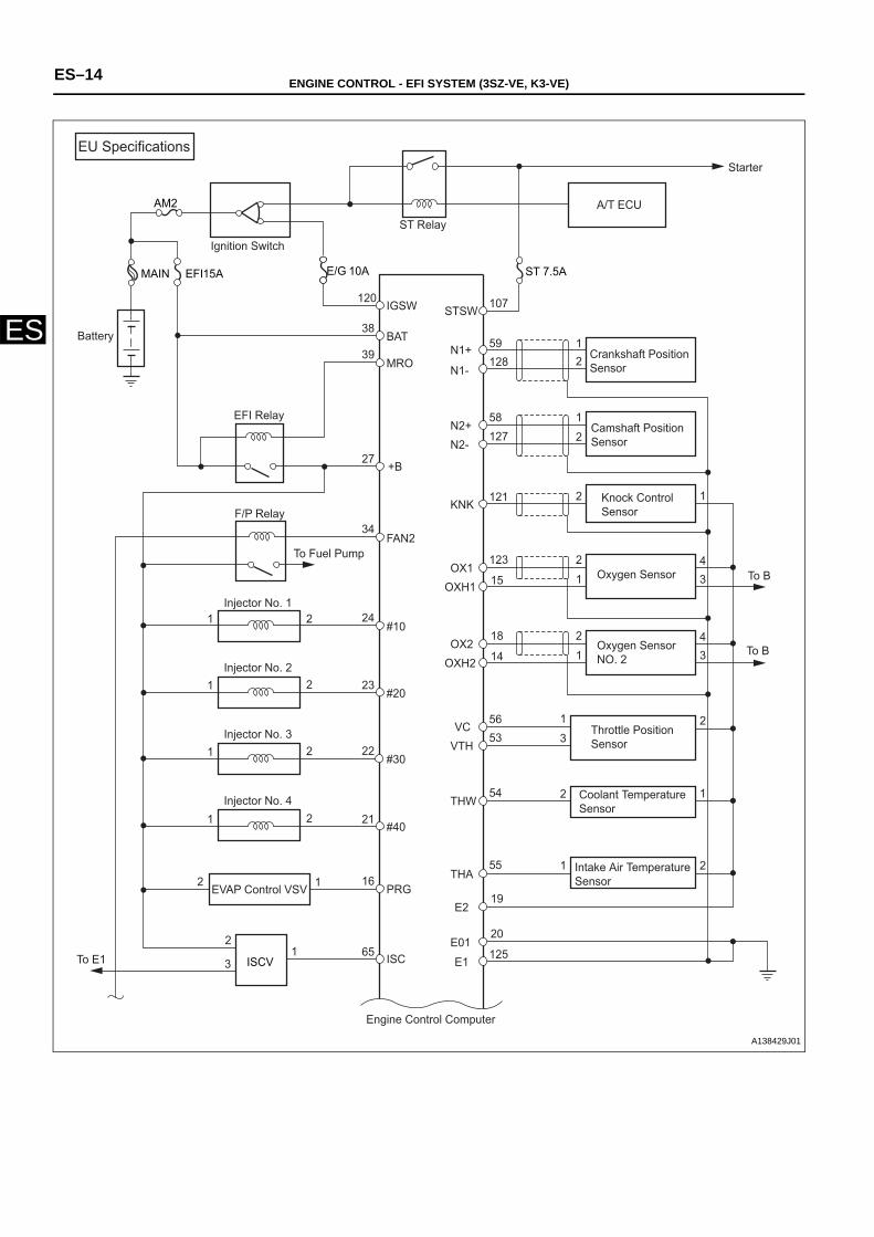
EU SpecificationsStarter
ST Relay
Ignition Switch
Battery
F/P Relay
Injector No. 1
Injector No. 2
Injector No. 3
Injector No. 4
EVAP Control VSV
To E1
Intake Air Temperature Sensor
Coolant Temperature Sensor
Crankshaft Position Sensor
To Fuel Pump
Engine Control Computer
E/G
AM2
MAIN ST 7.5A
ISCV
15A 10AEFI
STSW
N1+
N1-
N2+N2-
KNK
OX1OXH1
VCVTH
THW
THA
E2
E01
E1ISC
PRG
#40
#30
#20
#10
FAN2
+B
MRO
BAT
IGSW 107
59128
58127
121
123
15
5653
54
55
19
20
125
120
38
39
27
34
24
23
22
21
16
65
12
1
2
2 1
1
2
34
OX2OXH2
18
14 1
2
34
1 23
2 1
1 2
2
2
2
2
2
2
1
1
1
1
1
13
A/T ECU
Oxygen Sensor NO. 2
Oxygen Sensor
A138429J01
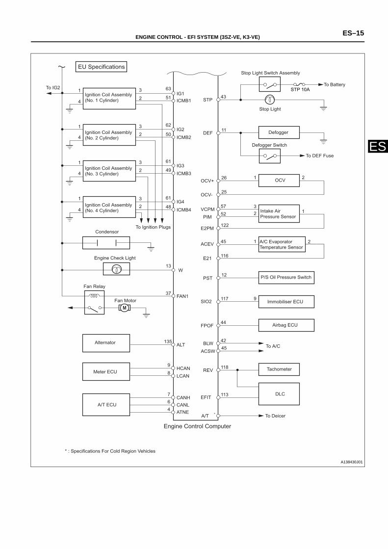
ENGINE CONTROL - EFI SYSTEM (3SZ-VE, K3-VE) ES–15
ESDefogger Switch
To DEF Fuse
Engine Control Computer
Engine Check Light
EU Specifications
Ignition Coil Assembly (No. 1 Cylinder)
Ignition Coil Assembly (No. 2 Cylinder)
Ignition Coil Assembly (No. 3 Cylinder)
Ignition Coil Assembly (No. 4 Cylinder)
Condensor To Ignition Plugs
Stop Light Switch Assembly
To Battery
Stop Light
Defogger
Fan Relay
Fan Motor
Alternator
Meter ECU Tachometer
Airbag ECU
Immobiliser ECU
P/S Oil Pressure Switch
A/C Evaporator Temperature Sensor
To A/C
Intake Air Pressure Sensor
To Deicer
* : Specifications For Cold Region Vehicles
To IG2 STP 10A
A/T ECU
DLC
OCV
STP
DEF
OCV+
OCV-
VCPMPIM
E2PM
ACEV
E21
PST
SIO2
FPOF
REV
A/T
EFIT
BLWACSW
ALT
HCANLCAN
CANHCANLATNE
FAN1
W
IG1ICMB1
ICMB2
ICMB3
ICMB4
IG2
IG3
IG4
43
11
26
25
5752
122
45
116
12
117
44
4245
118
113
63
51
62
50
61
49
61
48
13
37
135
9
8
764
1
1
132
9
2
2
3
2
2
2
2
3
3
3
1
1
1
1
4
4
4
4
*
A138430J01
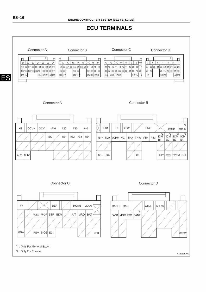
ES–16 ENGINE CONTROL - EFI SYSTEM (3SZ-VE, K3-VE)
ES
ECU TERMINALS
1234567
28
70
107108109110111112113114115116117118119120121122123124125126127128129130131132133134135
7172737475767778798081828384858687888990919293949596979899100101102103104105106
2930313233343536373839404142434445464748495051525354555657585960616263646566676869
891011121321222324252627 14151617181920
W DEF HCAN LCAN
ACEV FPOF STP BLW MROA/T BAT
IGSW REV SIO2 E21 EFIT
+B OCV+ OCV- #10 #20 #30 #40
IG4IG3IG2IG1ISC
ALT ALTC
OXH1 OXH2PRGOX2E2E01
N1+ N2+ VCPM VC THA THW VTH PIM
N1- N2- E1 OX1PST E2PM KNK
ICMB3
ICMB2
ICMB1
ICMB4
CANH CANL ATNE ACSW
FAN1 MGC FC1 FAN2
STSW
Connector BConnector A
Connector A Connector B Connector C Connector D
Connector D Connector C
*1 : Only For General Export
*2 : Only For Europe
*2 *2 *2 *2
*2
*2*1
A139505J01
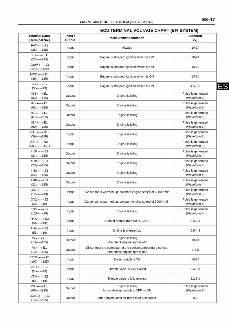
ENGINE CONTROL - EFI SYSTEM (3SZ-VE, K3-VE) ES–17
ES
ECU TERMINAL VOLTAGE CHART (EFI SYSTEM) Terminal Name(Terminal No.)
Input / Output Measurement condition Standard
(V)
BAT ←→ E1(38←→125)
Input Always 10-14
+B ←→ E1(27←→125)
Input Engine is stopped, ignition switch is ON 10-14
IGSW ←→ E1(120←→125)
Input Engine is stopped, ignition switch is ON 10-14
MRO ←→ E1(39←→125)
Input Engine is stopped, ignition switch is ON 10-14
VC ←→ E2(56←→19)
Input Engine is stopped, ignition switch is ON 4.5-5.5
IG1 ←→ E1(63←→125)
Output Engine is idlingPulse is generated
(Waveform 1)
IG2 ←→ E1(62←→125)
Output Engine is idlingPulse is generated
(Waveform 1)
IG3 ←→ E1(61←→125)
Output Engine is idlingPulse is generated
(Waveform 1)
IG4 ←→ E1(60←→125)
Output Engine is idlingPulse is generated
(Waveform 1)
N1+ ←→ N1-(59←→128)
Input Engine is idlingPulse is generated
(Waveform 2)
N2+ ←→ N2-(58 ←→ B127)
Input Engine is idlingPulse is generated
(Waveform 3)
# 10 ←→ E1(24←→125)
Output Engine is idlingPulse is generated
(Waveform 4)
# 20 ←→ E1(23←→125)
Output Engine is idlingPulse is generated
(Waveform 4)
# 30 ←→ E1(22←→125)
Output Engine is idlingPulse is generated
(Waveform 4)
# 40 ←→ E1(21←→125)
Output Engine is idlingPulse is generated
(Waveform 4)
OX1 ←→ E2(123←→19)
Input O2 sensor is warmed up, constant engine speed of 3000 r/min Pulse is generated
(Waveform 5)
OX2 ←→ E2(18←→19)
Input O2 sensor is warmed up, constant engine speed of 3000 r/min Pulse is generated
(Waveform 5)
KNK ←→ E2(121←→19)
Input Engine is idlingPulse is generated
(Waveform 6)
THW ←→ E2(54←→19)
Input Coolant temperature 60 to 120°C 0.3-1.3
THA ←→ E2(55←→19)
Input Engine is warmed up 0.5-4.3
W ←→ E1(13←→125)
OutputEngine is idling
(the check engine light is off) 10-14
W ←→ E1(13←→125)
OutputDisconnect the connector of the coolant temperature sensor.
(the check engine light is on) 0-3.5
STSW ←→ E1(107←→125)
Input Starter switch is ON 10-14
VTH ←→ E2(53←→19)
Input Throttle valve is fully closed 0.4-0.8
VTH ←→ E2(53←→19)
Input Throttle valve is fully opened 3.2-5.0
ISC ←→ E1(65←→125)
OutputEngine is idling
Air conditioner switch is OFF → ONPulse is generated
(Waveform 7)
OXH1 ←→ E1(15←→125)
Output After engine idles for more than 5 seconds 0-1
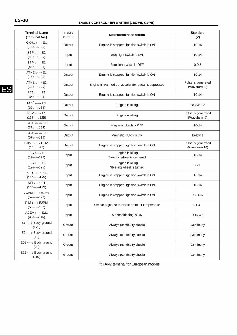
ES–18 ENGINE CONTROL - EFI SYSTEM (3SZ-VE, K3-VE)
ES
*: FAN2 terminal for European models
OXH1 ←→ E1(15←→125)
Output Engine is stopped, ignition switch is ON 10-14
STP ←→ E1(43←→125)
Input Stop light switch is ON 10-14
STP ←→ E1(43←→125)
Input Stop light switch is OFF 0-0.5
ATNE ←→ E1(16←→125)
Output Engine is stopped, ignition switch is ON 10-14
ATNE ←→ E1(16←→125)
Output Engine is warmed up, accelerator pedal is depressedPulse is generated
(Waveform 8)
FC1 ←→ E1(35←→125)
Output Engine is stopped, ignition switch is ON 10-14
FC1* ←→ E1(35←→125)
Output Engine is idling Below 1.2
REV ←→ E1(118←→125)
Output Engine is idlingPulse is generated
(Waveform 9)
FAN1 ←→ E1(37←→125)
Output Magnetic clutch is OFF 10-14
FAN1 ←→ E1(37←→125)
Output Magnetic clutch is ON Below 1
OCV+ ←→ OCV-(26←→25)
Output Engine is stopped, ignition switch is ON Pulse is generated
(Waveform 10)
EPS ←→ E1(12←→125)
InputEngine is idling
Steering wheel is centered10-14
EPS ←→ E1(12←→125)
InputEngine is idling
Steering wheel is turned 0-1
ALTC ←→ E1(134←→125)
Input Engine is stopped, ignition switch is ON 10-14
ALT ←→ E1(135←→125)
Input Engine is stopped, ignition switch is ON 10-14
VCPM ←→ E2PM(57←→122)
Input Engine is stopped, ignition switch is ON 4.5-5.5
PIM ←→ E2PM(52←→122)
Input Sensor adjusted to stable ambient temperature 3.1-4.1
ACEV ←→ E21(45←→116)
Input Air conditioning is ON 0.15-4.8
E1 ←→ Body ground(125)
Ground Always (continuity check) Continuity
E2 ←→ Body ground(19)
Ground Always (continuity check) Continuity
E01 ←→ Body ground(20)
Ground Always (continuity check) Continuity
E21 ←→ Body ground(116)
Ground Always (continuity check) Continuity
Terminal Name(Terminal No.)
Input / Output Measurement condition Standard
(V)
ENGINE CONTROL - EFI SYSTEM (3SZ-VE, K3-VE) ES–19
ES
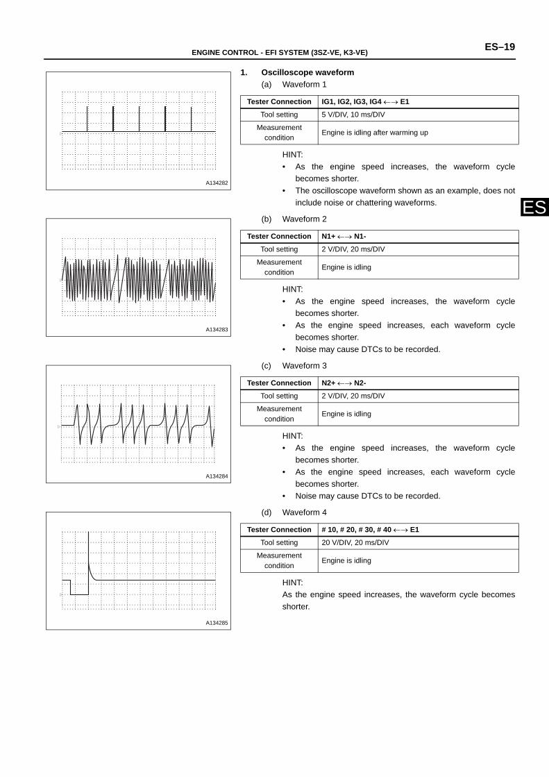
1. Oscilloscope waveform(a) Waveform 1
HINT:• As the engine speed increases, the waveform cycle
becomes shorter.• The oscilloscope waveform shown as an example, does not
include noise or chattering waveforms.
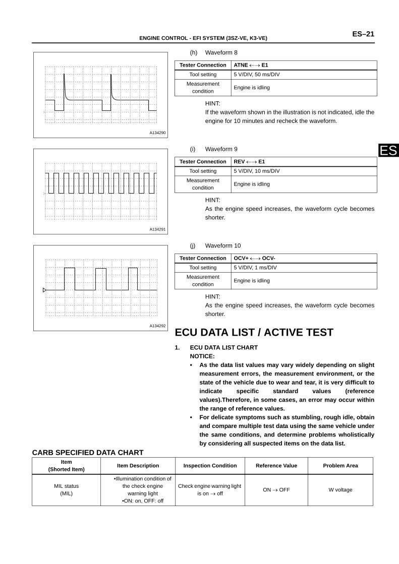
(b) Waveform 2
HINT:• As the engine speed increases, the waveform cycle
becomes shorter. • As the engine speed increases, each waveform cycle
becomes shorter. • Noise may cause DTCs to be recorded.
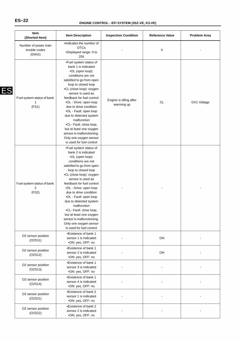
(c) Waveform 3
HINT:• As the engine speed increases, the waveform cycle
becomes shorter. • As the engine speed increases, each waveform cycle
becomes shorter. • Noise may cause DTCs to be recorded.
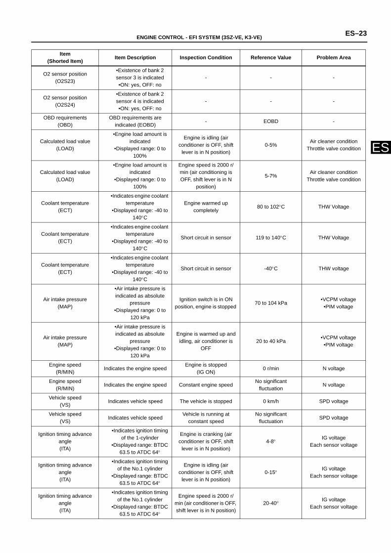
(d) Waveform 4
HINT:As the engine speed increases, the waveform cycle becomesshorter.
A134282
Tester Connection IG1, IG2, IG3, IG4 ←→ E1
Tool setting 5 V/DIV, 10 ms/DIV
Measurement condition
Engine is idling after warming up
A134283
Tester Connection N1+ ←→ N1-
Tool setting 2 V/DIV, 20 ms/DIV
Measurement condition
Engine is idling
A134284
Tester Connection N2+ ←→ N2-
Tool setting 2 V/DIV, 20 ms/DIV
Measurement condition
Engine is idling
A134285
Tester Connection # 10, # 20, # 30, # 40 ←→ E1
Tool setting 20 V/DIV, 20 ms/DIV
Measurement condition
Engine is idling

ES–20 ENGINE CONTROL - EFI SYSTEM (3SZ-VE, K3-VE)
ES
(e) Waveform 5
HINT:Repeat between 0 (LEAN) ←→ 1(RICH)V
(f) Waveform 6
HINT:• The oscilloscope waveform shown as an example does not
include noise or chattering waveforms. • The waveform amplitudes differ slightly depending on the
vehicle.
(g) Waveform 7
HINT:The duty ratio changes if the air conditioning is turned ON.
A134286
Tester Connection OX1, OX2 ←→ E1
Tool setting 0.2 V/DIV, 500 ms/DIV
Measurement condition
Oxygen sensor is warmed up, constant engine speed of 3000 r/min
A134287
Tester Connection KNK ←→ E1
Tool setting 1 V/DIV, 1 ms/DIV.
Measurement condition
Engine is idling
Air Conditioner OFF
Air Conditioner ON
A134289
Tester Connection ISC ←→ E1
Tool setting 5 V/DIV, 1 ms/DIV
Measurement condition
Engine is idling, air conditioning is OFF → ON
ENGINE CONTROL - EFI SYSTEM (3SZ-VE, K3-VE) ES–21
ES
(h) Waveform 8
HINT:If the waveform shown in the illustration is not indicated, idle theengine for 10 minutes and recheck the waveform.
(i) Waveform 9
HINT:As the engine speed increases, the waveform cycle becomesshorter.
(j) Waveform 10
HINT:As the engine speed increases, the waveform cycle becomesshorter.
ECU DATA LIST / ACTIVE TEST1. ECU DATA LIST CHART
NOTICE:• As the data list values may vary widely depending on slight
measurement errors, the measurement environment, or thestate of the vehicle due to wear and tear, it is very difficult toindicate specific standard values (referencevalues).Therefore, in some cases, an error may occur withinthe range of reference values.
• For delicate symptoms such as stumbling, rough idle, obtainand compare multiple test data using the same vehicle underthe same conditions, and determine problems wholisticallyby considering all suspected items on the data list.
CARB SPECIFIED DATA CHART
A134290
Tester Connection ATNE ←→ E1
Tool setting 5 V/DIV, 50 ms/DIV
Measurement condition
Engine is idling
A134291
Tester Connection REV ←→ E1
Tool setting 5 V/DIV, 10 ms/DIV
Measurement condition
Engine is idling
A134292
Tester Connection OCV+ ←→ OCV-
Tool setting 5 V/DIV, 1 ms/DIV
Measurement condition
Engine is idling
Item(Shorted Item) Item Description Inspection Condition Reference Value Problem Area
MIL status(MIL)
•Illumination condition of the check engine
warning light•ON: on, OFF: off
Check engine warning light is on → off
ON → OFF W voltage
ES–22 ENGINE CONTROL - EFI SYSTEM (3SZ-VE, K3-VE)
ES
Number of power train trouble codes
(DIAG)
•Indicates the number of DTCs
•Displayed range: 0 to 255
- 0 -
Fuel system status of bank 1
(FS1)
•Fuel system status of bank 1 is indicated •OL (open loop):
conditions are not satisfied to go from open
loop to closed loop•CL (close loop): oxygen
sensor is used as feedback for fuel control •OL - Drive: open loop due to drive condition•OL - Fault: open loop
due to detected system malfunction
•CL- Fault: close loop, but at least one oxygen
sensor is malfunctioning. Only one oxygen sensor is used for fuel control
Engine is idling after warming up
CL OX1 Voltage
Fuel system status of bank 2
(FS2)
•Fuel system status of bank 2 is indicated •OL (open loop):
conditions are not satisfied to go from open
loop to closed loop•CL (close loop): oxygen
sensor is used as feedback for fuel control •OL - Drive: open loop due to drive condition•OL - Fault: open loop
due to detected system malfunction
•CL- Fault: close loop, but at least one oxygen
sensor is malfunctioning. Only one oxygen sensor is used for fuel control
- - -
O2 sensor position(O2S11)
•Existence of bank 1 sensor 1 is indicated •ON: yes, OFF: no
- ON -
O2 sensor position(O2S12)
•Existence of bank 1 sensor 2 is indicated •ON: yes, OFF: no
- ON -
O2 sensor position(O2S13)
•Existence of bank 1 sensor 3 is indicated •ON: yes, OFF: no
- - -
O2 sensor position(O2S14)
•Existence of bank 1 sensor 4 is indicated •ON: yes, OFF: no
- - -
O2 sensor position(O2S21)
•Existence of bank 2 sensor 1 is indicated •ON: yes, OFF: no
- - -
O2 sensor position(O2S22)
•Existence of bank 2 sensor 2 is indicated •ON: yes, OFF: no
- - -
Item(Shorted Item) Item Description Inspection Condition Reference Value Problem Area
ENGINE CONTROL - EFI SYSTEM (3SZ-VE, K3-VE) ES–23
ES
O2 sensor position(O2S23)
•Existence of bank 2 sensor 3 is indicated •ON: yes, OFF: no
- - -
O2 sensor position(O2S24)
•Existence of bank 2 sensor 4 is indicated •ON: yes, OFF: no
- - -
OBD requirements(OBD)
OBD requirements are indicated (EOBD)
- EOBD -
Calculated load value (LOAD)
•Engine load amount is indicated
•Displayed range: 0 to 100%
Engine is idling (air conditioner is OFF, shift
lever is in N position)0-5%
Air cleaner condition Throttle valve condition
Calculated load value (LOAD)
•Engine load amount is indicated
•Displayed range: 0 to 100%
Engine speed is 2000 r/min (air conditioning is OFF, shift lever is in N
position)
5-7%Air cleaner condition
Throttle valve condition
Coolant temperature(ECT)
•Indicates engine coolant temperature
•Displayed range: -40 to 140°C
Engine warmed up completely
80 to 102°C THW Voltage
Coolant temperature(ECT)
•Indicates engine coolant temperature
•Displayed range: -40 to 140°C
Short circuit in sensor 119 to 140°C THW Voltage
Coolant temperature(ECT)
•Indicates engine coolant temperature
•Displayed range: -40 to 140°C
Short circuit in sensor -40°C THW voltage
Air intake pressure(MAP)
•Air intake pressure is indicated as absolute
pressure•Displayed range: 0 to
120 kPa
Ignition switch is in ON position, engine is stopped
70 to 104 kPa•VCPM voltage
•PIM voltage
Air intake pressure(MAP)
•Air intake pressure is indicated as absolute
pressure•Displayed range: 0 to
120 kPa
Engine is warmed up and idling, air conditioner is
OFF 20 to 40 kPa
•VCPM voltage•PIM voltage
Engine speed(R/MIN)
Indicates the engine speedEngine is stopped
(IG ON)0 r/min N voltage
Engine speed(R/MIN)
Indicates the engine speed Constant engine speedNo significant
fluctuationN voltage
Vehicle speed(VS)
Indicates vehicle speed The vehicle is stopped 0 km/h SPD voltage
Vehicle speed(VS)
Indicates vehicle speedVehicle is running at
constant speedNo significant
fluctuationSPD voltage
Ignition timing advance angle (ITA)
•Indicates ignition timing of the 1-cylinder
•Displayed range: BTDC 63.5 to ATDC 64°
Engine is cranking (air conditioner is OFF, shift
lever is in N position)4-8°
IG voltage Each sensor voltage
Ignition timing advance angle (ITA)
•Indicates ignition timing of the No.1 cylinder
•Displayed range: BTDC 63.5 to ATDC 64°
Engine is idling (air conditioner is OFF, shift
lever is in N position)0-15°
IG voltage Each sensor voltage
Ignition timing advance angle (ITA)
•Indicates ignition timing of the No.1 cylinder
•Displayed range: BTDC 63.5 to ATDC 64°
Engine speed is 2000 r/min (air conditioner is OFF, shift lever is in N position)
20-40°IG voltage
Each sensor voltage
Item(Shorted Item) Item Description Inspection Condition Reference Value Problem Area
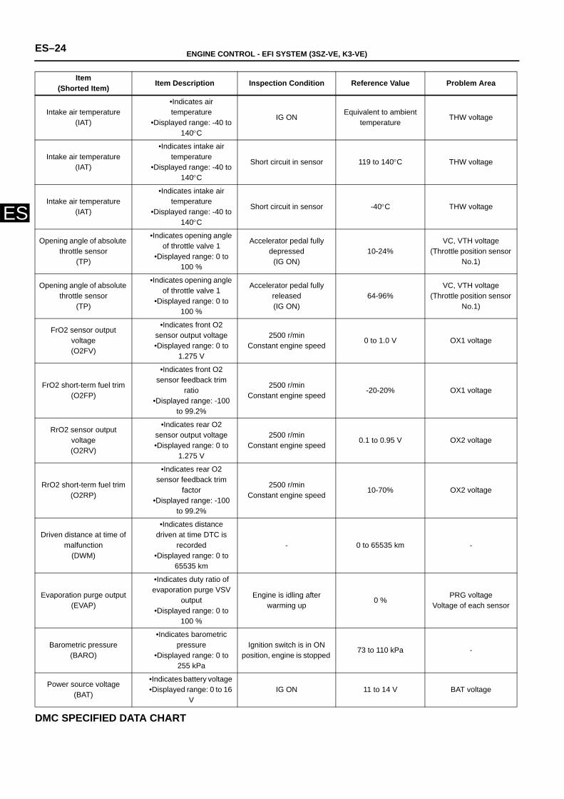
ES–24 ENGINE CONTROL - EFI SYSTEM (3SZ-VE, K3-VE)
ES
DMC SPECIFIED DATA CHART
Intake air temperature(IAT)
•Indicates air temperature
•Displayed range: -40 to 140°C
IG ONEquivalent to ambient
temperatureTHW voltage
Intake air temperature(IAT)
•Indicates intake air temperature
•Displayed range: -40 to 140°C
Short circuit in sensor 119 to 140°C THW voltage
Intake air temperature(IAT)
•Indicates intake air temperature
•Displayed range: -40 to 140°C
Short circuit in sensor -40°C THW voltage
Opening angle of absolute throttle sensor
(TP)
•Indicates opening angle of throttle valve 1
•Displayed range: 0 to 100 %
Accelerator pedal fully depressed
(IG ON)10-24%
VC, VTH voltage(Throttle position sensor
No.1)
Opening angle of absolute throttle sensor
(TP)
•Indicates opening angle of throttle valve 1
•Displayed range: 0 to 100 %
Accelerator pedal fully released (IG ON)
64-96%VC, VTH voltage
(Throttle position sensor No.1)
FrO2 sensor output voltage(O2FV)
•Indicates front O2 sensor output voltage•Displayed range: 0 to
1.275 V
2500 r/minConstant engine speed
0 to 1.0 V OX1 voltage
FrO2 short-term fuel trim (O2FP)
•Indicates front O2 sensor feedback trim
ratio•Displayed range: -100
to 99.2%
2500 r/minConstant engine speed
-20-20% OX1 voltage
RrO2 sensor output voltage(O2RV)
•Indicates rear O2 sensor output voltage•Displayed range: 0 to
1.275 V
2500 r/minConstant engine speed
0.1 to 0.95 V OX2 voltage
RrO2 short-term fuel trim(O2RP)
•Indicates rear O2 sensor feedback trim
factor•Displayed range: -100
to 99.2%
2500 r/minConstant engine speed
10-70% OX2 voltage
Driven distance at time of malfunction
(DWM)
•Indicates distance driven at time DTC is
recorded•Displayed range: 0 to
65535 km
- 0 to 65535 km -
Evaporation purge output(EVAP)
•Indicates duty ratio of evaporation purge VSV
output•Displayed range: 0 to
100 %
Engine is idling after warming up
0 %PRG voltage
Voltage of each sensor
Barometric pressure(BARO)
•Indicates barometric pressure
•Displayed range: 0 to 255 kPa
Ignition switch is in ON position, engine is stopped
73 to 110 kPa -
Power source voltage(BAT)
•Indicates battery voltage •Displayed range: 0 to 16
V IG ON 11 to 14 V BAT voltage
Item(Shorted Item) Item Description Inspection Condition Reference Value Problem Area
ENGINE CONTROL - EFI SYSTEM (3SZ-VE, K3-VE) ES–25
ES
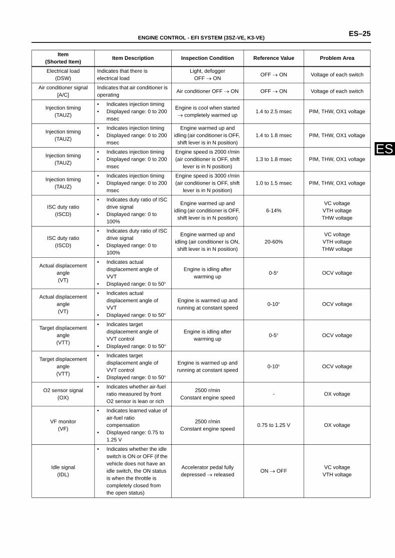
Item(Shorted Item) Item Description Inspection Condition Reference Value Problem Area
Electrical load(DSW)
Indicates that there is electrical load
Light, defogger OFF → ON
OFF → ON Voltage of each switch
Air conditioner signal[A/C]
Indicates that air conditioner is operating
Air conditioner OFF → ON OFF → ON Voltage of each switch
Injection timing(TAUZ)
• Indicates injection timing • Displayed range: 0 to 200
msec
Engine is cool when started → completely warmed up
1.4 to 2.5 msec PIM, THW, OX1 voltage
Injection timing(TAUZ)
• Indicates injection timing • Displayed range: 0 to 200
msec
Engine warmed up and idling (air conditioner is OFF,
shift lever is in N position)1.4 to 1.8 msec PIM, THW, OX1 voltage
Injection timing(TAUZ)
• Indicates injection timing• Displayed range: 0 to 200
msec
Engine speed is 2000 r/min (air conditioner is OFF, shift
lever is in N position)1.3 to 1.8 msec PIM, THW, OX1 voltage
Injection timing(TAUZ)
• Indicates injection timing• Displayed range: 0 to 200
msec
Engine speed is 3000 r/min (air conditioner is OFF, shift
lever is in N position)1.0 to 1.5 msec PIM, THW, OX1 voltage
ISC duty ratio(ISCD)
• Indicates duty ratio of ISC drive signal
• Displayed range: 0 to 100%
Engine warmed up and idling (air conditioner is OFF,
shift lever is in N position)6-14%
VC voltageVTH voltageTHW voltage
ISC duty ratio(ISCD)
• Indicates duty ratio of ISC drive signal
• Displayed range: 0 to 100%
Engine warmed up and idling (air conditioner is ON, shift lever is in N position)
20-60%VC voltage
VTH voltageTHW voltage
Actual displacement angle(VT)
• Indicates actual displacement angle of VVT
• Displayed range: 0 to 50°
Engine is idling after warming up
0-5° OCV voltage
Actual displacement angle(VT)
• Indicates actual displacement angle of VVT
• Displayed range: 0 to 50°
Engine is warmed up and running at constant speed
0-10° OCV voltage
Target displacement angle (VTT)
• Indicates target displacement angle of VVT control
• Displayed range: 0 to 50°
Engine is idling after warming up
0-5° OCV voltage
Target displacement angle (VTT)
• Indicates target displacement angle of VVT control
• Displayed range: 0 to 50°
Engine is warmed up and running at constant speed
0-10° OCV voltage
O2 sensor signal(OX)
• Indicates whether air-fuel ratio measured by front O2 sensor is lean or rich
2500 r/minConstant engine speed
- OX voltage
VF monitor(VF)
• Indicates learned value of air-fuel ratio compensation
• Displayed range: 0.75 to 1.25 V
2500 r/minConstant engine speed
0.75 to 1.25 V OX voltage
Idle signal(IDL)
• Indicates whether the idle switch is ON or OFF (if the vehicle does not have an idle switch, the ON status is when the throttle is completely closed from the open status)
Accelerator pedal fully depressed → released
ON → OFFVC voltage
VTH voltage
ES–26 ENGINE CONTROL - EFI SYSTEM (3SZ-VE, K3-VE)
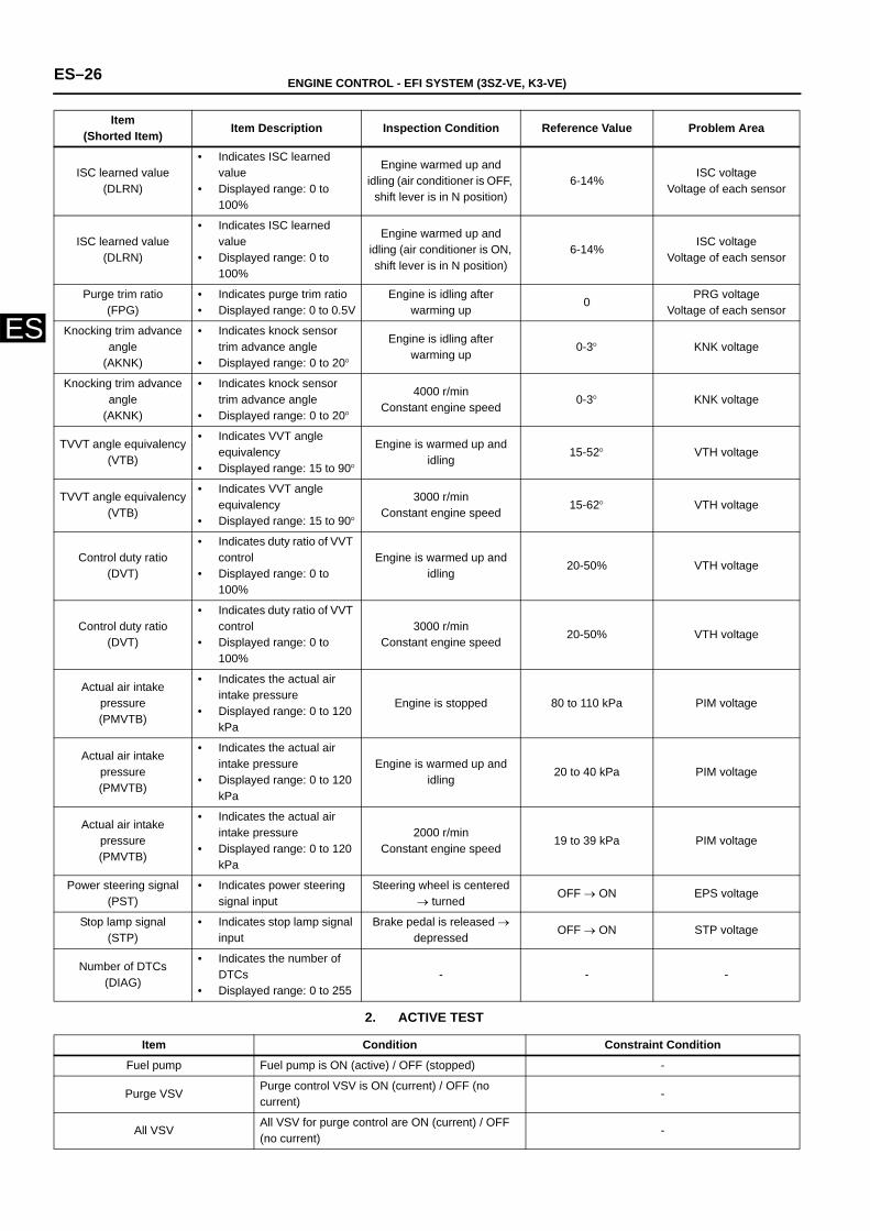
ES
2. ACTIVE TEST
ISC learned value(DLRN)
• Indicates ISC learned value
• Displayed range: 0 to 100%
Engine warmed up and idling (air conditioner is OFF,
shift lever is in N position)6-14%
ISC voltageVoltage of each sensor
ISC learned value(DLRN)
• Indicates ISC learned value
• Displayed range: 0 to 100%
Engine warmed up and idling (air conditioner is ON, shift lever is in N position)
6-14%ISC voltage
Voltage of each sensor
Purge trim ratio(FPG)
• Indicates purge trim ratio• Displayed range: 0 to 0.5V
Engine is idling after warming up
0PRG voltage
Voltage of each sensor
Knocking trim advance angle
(AKNK)
• Indicates knock sensor trim advance angle
• Displayed range: 0 to 20°
Engine is idling after warming up
0-3° KNK voltage
Knocking trim advance angle
(AKNK)
• Indicates knock sensor trim advance angle
• Displayed range: 0 to 20°
4000 r/minConstant engine speed
0-3° KNK voltage
TVVT angle equivalency(VTB)
• Indicates VVT angle equivalency
• Displayed range: 15 to 90°
Engine is warmed up and idling
15-52° VTH voltage
TVVT angle equivalency(VTB)
• Indicates VVT angle equivalency
• Displayed range: 15 to 90°
3000 r/minConstant engine speed
15-62° VTH voltage
Control duty ratio (DVT)
• Indicates duty ratio of VVT control
• Displayed range: 0 to 100%
Engine is warmed up and idling
20-50% VTH voltage
Control duty ratio (DVT)
• Indicates duty ratio of VVT control
• Displayed range: 0 to 100%
3000 r/minConstant engine speed
20-50% VTH voltage
Actual air intake pressure(PMVTB)
• Indicates the actual air intake pressure
• Displayed range: 0 to 120 kPa
Engine is stopped 80 to 110 kPa PIM voltage
Actual air intake pressure(PMVTB)
• Indicates the actual air intake pressure
• Displayed range: 0 to 120 kPa
Engine is warmed up and idling
20 to 40 kPa PIM voltage
Actual air intake pressure(PMVTB)
• Indicates the actual air intake pressure
• Displayed range: 0 to 120 kPa
2000 r/minConstant engine speed
19 to 39 kPa PIM voltage
Power steering signal(PST)
• Indicates power steering signal input
Steering wheel is centered → turned
OFF → ON EPS voltage
Stop lamp signal(STP)
• Indicates stop lamp signal input
Brake pedal is released → depressed
OFF → ON STP voltage
Number of DTCs(DIAG)
• Indicates the number of DTCs
• Displayed range: 0 to 255 - - -
Item(Shorted Item) Item Description Inspection Condition Reference Value Problem Area
Item Condition Constraint Condition
Fuel pump Fuel pump is ON (active) / OFF (stopped) -
Purge VSVPurge control VSV is ON (current) / OFF (no current)
-
All VSVAll VSV for purge control are ON (current) / OFF (no current)
-
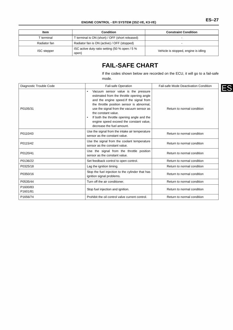
ENGINE CONTROL - EFI SYSTEM (3SZ-VE, K3-VE) ES–27
ES
FAIL-SAFE CHARTIf the codes shown below are recorded on the ECU, it will go to a fail-safemode.
T terminal T terminal is ON (short) / OFF (short released) -
Radiator fan Radiator fan is ON (active) / OFF (stopped) -
ISC stepperISC active duty ratio setting (50 % open / 5 % open)
Vehicle is stopped, engine is idling
Item Condition Constraint Condition
Diagnostic Trouble Code Fail-safe Operation Fail-safe Mode Deactivation Condition
P0105/31
• Vacuum sensor value is the pressureestimated from the throttle opening angleand the engine speed.If the signal fromthe throttle position sensor is abnormal,use the signal from the vacuum sensor asthe constant value.
• If both the throttle opening angle and theengine speed exceed the constant value,decrease the fuel amount.
Return to normal condition
P0110/43Use the signal from the intake air temperaturesensor as the constant value.
Return to normal condition
P0115/42Use the signal from the coolant temperaturesensor as the constant value.
Return to normal condition
P0120/41Use the signal from the throttle positionsensor as the constant value.
Return to normal condition
P0136/22 Set feedback control to open control. Return to normal condition
P0325/18 Lag the ignition timing. Return to normal condition
P0350/16Stop the fuel injection to the cylinder that hasignition signal problems.
Return to normal condition
P0535/44 Turn off the air conditioner. Return to normal condition
P1600/83P1601/81
Stop fuel injection and ignition. Return to normal condition
P1656/74 Prohibit the oil control valve current control. Return to normal condition
ES–28 ENGINE CONTROL - EFI SYSTEM (3SZ-VE, K3-VE)
ES
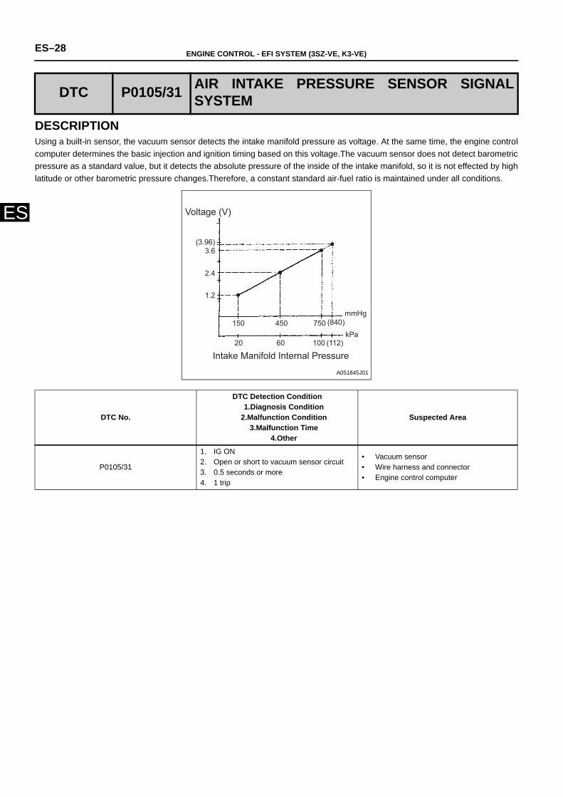
DESCRIPTIONUsing a built-in sensor, the vacuum sensor detects the intake manifold pressure as voltage. At the same time, the engine controlcomputer determines the basic injection and ignition timing based on this voltage.The vacuum sensor does not detect barometricpressure as a standard value, but it detects the absolute pressure of the inside of the intake manifold, so it is not effected by highlatitude or other barometric pressure changes.Therefore, a constant standard air-fuel ratio is maintained under all conditions.
DTC P0105/31 AIR INTAKE PRESSURE SENSOR SIGNALSYSTEM
DTC No.
DTC Detection Condition1.Diagnosis Condition
2.Malfunction Condition3.Malfunction Time
4.Other
Suspected Area
P0105/31
1. IG ON2. Open or short to vacuum sensor circuit3. 0.5 seconds or more4. 1 trip
• Vacuum sensor• Wire harness and connector• Engine control computer
(3.96)3.6
2.4
1.2
150 450 750 (840)mmHg
20 60 100 (112)kPa
Voltage (V)
Intake Manifold Internal Pressure
A051845J01
ENGINE CONTROL - EFI SYSTEM (3SZ-VE, K3-VE) ES–29
ES
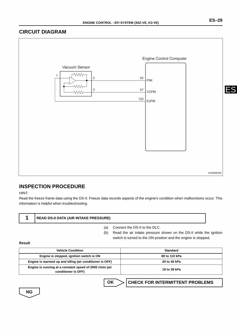
CIRCUIT DIAGRAM
INSPECTION PROCEDUREHINT:Read the freeze frame data using the DS-II. Freeze data records aspects of the engine's condition when malfunctions occur. Thisinformation is helpful when troubleshooting.
(a) Connect the DS-II to the DLC.(b) Read the air intake pressure shown on the DS-II while the ignition
switch is turned to the ON position and the engine is stopped.Result
OK
NG
1 READ DS-II DATA (AIR INTAKE PRESSURE)
Vacuum Sensor
Engine Control Computer
1
3
2 52
57
122
PIM
VCPM
E2PM
A133545J02
Vehicle Condition Standard
Engine is stopped, ignition switch is ON 80 to 110 kPa
Engine is warmed up and idling (air conditioner is OFF) 20 to 40 kPa
Engine is running at a constant speed of 2000 r/min (air conditioner is OFF) 19 to 39 kPa
CHECK FOR INTERMITTENT PROBLEMS

ES–30 ENGINE CONTROL - EFI SYSTEM (3SZ-VE, K3-VE)
ES
(a) Disconnect the vacuum sensor connector and the engine controlcomputer connector B.
(b) Using a tester, check whether there is continuity or a short betweenthe engine control computer and the vacuum sensor.(For terminallayout, see page ES - 16.)Standard
NG
OK
(a) Turn the ignition switch to the ON position.(b) Measure the voltage between the terminals of the vacuum sensor
connecter using the tester.Standard
(c) Remove the fuel pump relay and crank the engine, then measure thevoltage between the terminals of the vacuum sensor connector.Standard
OK
NG
2 CHECK WIRE HARNESS AND CONNECTOR (ENGINE CONTROL COMPUTER VACUUM SENSOR)
Engine Control Computer
Intake Pressure Sensor Vehicle Side Connector
E2PMPIMVCPM
E2 PIM VC
A133546J01
Inspection Terminal (Terminal Name)Engine control computer ←→
Vacuum sensor Standard
57 (VCPM) ←→ 3 (VC) There is continuity and no shorts between other terminals and body
ground 52 (PIM) ←→ 2 (PIM)
122 (E2PM) ←→ 1 (E2) There is continuity, and no shortbetween other terminals
REPAIR OR REPLACE WIRE HARNESS ORCONNECTOR
3 CHECK VACUUM SENSOR
1 2 3
Intake Pressure Sensor
E2 PIM VC
A133547J01
Inspection Terminal (Terminal Name) Standard
3 (VC) ←→ 1 (E2) 4.5 to 5.5 V
2 (PIM) ←→ 1 (E2) 3.1 to 4.1 V
Inspection Terminal (Terminal Name) Standard
2 (PIM) ←→ 1 (E2) Voltage value fluctuates
REPLACE THE VACUUM SENSOR
CHECK AND REPLACE ENGINE ECU
ENGINE CONTROL - EFI SYSTEM (3SZ-VE, K3-VE) ES–31
ES
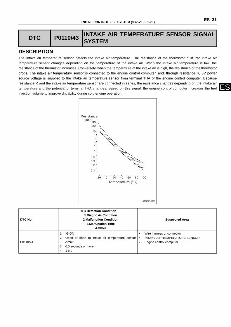
DESCRIPTIONThe intake air temperature sensor detects the intake air temperature. The resistance of the thermistor built into intake airtemperature sensor changes depending on the temperature of the intake air. When the intake air temperature is low, theresistance of the thermistor increases. Conversely, when the temperature of the intake air is high, the resistance of the thermistordrops. The intake air temperature sensor is connected to the engine control computer, and, through resistance R, 5V powersource voltage is supplied to the intake air temperature sensor from terminal THA of the engine control computer. Becauseresistance R and the intake air temperature sensor are connected in series, the resistance changes depending on the intake airtemperature and the potential of terminal THA changes. Based on this signal, the engine control computer increases the fuelinjection volume to improve drivability during cold engine operation.
DTC P0110/43 INTAKE AIR TEMPERATURE SENSOR SIGNALSYSTEM
DTC No.
DTC Detection Condition1.Diagnosis Condition
2.Malfunction Condition3.Malfunction Time
4.Other
Suspected Area
P0110/24
1. IG ON2. Open or short to intake air temperature sensor
circuit3. 0.5 seconds or more4. 1 trip
• Wire harness or connector• INTAKE AIR TEMPERATURE SENSOR• Engine control computer
-20 0 20 40 60 80 100
0.1
0.20.30.5
1
235
10
2030
Resistance [kΩ]
Temperature [°C]
A032255J11
ES–32 ENGINE CONTROL - EFI SYSTEM (3SZ-VE, K3-VE)
ES
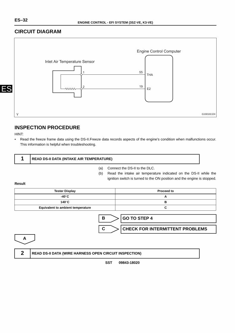
CIRCUIT DIAGRAM
INSPECTION PROCEDUREHINT:• Read the freeze frame data using the DS-II.Freeze data records aspects of the engine's condition when malfunctions occur.
This information is helpful when troubleshooting.
(a) Connect the DS-II to the DLC.(b) Read the intake air temperature indicated on the DS-II while the
ignition switch is turned to the ON position and the engine is stopped.Result
B
C
A
SST 09843-18020
1 READ DS-II DATA (INTAKE AIR TEMPERATURE)
Engine Control Computer
Inlet Air Temperature Sensor
THA
E2
1
2
55
19
G100102J24
Tester Display Proceed to
-40°C A
140°C B
Equivalent to ambient temperature C
GO TO STEP 4
CHECK FOR INTERMITTENT PROBLEMS
2 READ DS-II DATA (WIRE HARNESS OPEN CIRCUIT INSPECTION)
ENGINE CONTROL - EFI SYSTEM (3SZ-VE, K3-VE) ES–33
ES
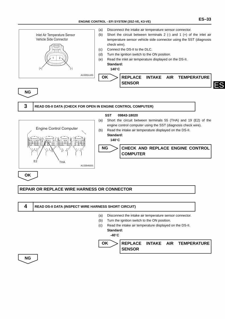
(a) Disconnect the intake air temperature sensor connector.(b) Short the circuit between terminals 2 (-) and 1 (+) of the inlet air
temperature sensor vehicle side connector using the SST (diagnosischeck wire).
(c) Connect the DS-II to the DLC.(d) Turn the ignition switch to the ON position.(e) Read the inlet air temperature displayed on the DS-II.
Standard:140°C
OK
NG
SST 09843-18020(a) Short the circuit between terminals 55 (THA) and 19 (E2) of the
engine control computer using the SST (diagnosis check wire).(b) Read the intake air temperature displayed on the DS-II.
Standard:140°C
NG
OK
(a) Disconnect the intake air temperature sensor connector.(b) Turn the ignition switch to the ON position.(c) Read the intake air temperature displayed on the DS-II.
Standard:-40°C
OK
NG
Inlet Air Temperature Sensor Vehicle Side Connector
(+) (-)
A133551J01 REPLACE INTAKE AIR TEMPERATURESENSOR
3 READ DS-II DATA (CHECK FOR OPEN IN ENGINE CONTROL COMPUTER)
Engine Control Computer
THAE2A133549J01
CHECK AND REPLACE ENGINE CONTROLCOMPUTER
REPAIR OR REPLACE WIRE HARNESS OR CONNECTOR
4 READ DS-II DATA (INSPECT WIRE HARNESS SHORT CIRCUIT)
REPLACE INTAKE AIR TEMPERATURESENSOR
ES–34 ENGINE CONTROL - EFI SYSTEM (3SZ-VE, K3-VE)
ES
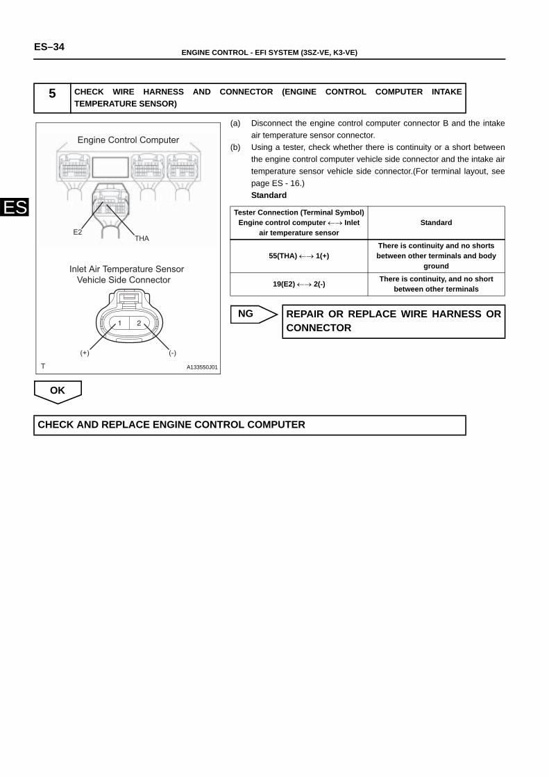
(a) Disconnect the engine control computer connector B and the intakeair temperature sensor connector.
(b) Using a tester, check whether there is continuity or a short betweenthe engine control computer vehicle side connector and the intake airtemperature sensor vehicle side connector.(For terminal layout, seepage ES - 16.)Standard
NG
OK
5 CHECK WIRE HARNESS AND CONNECTOR (ENGINE CONTROL COMPUTER INTAKETEMPERATURE SENSOR)
Engine Control Computer
Inlet Air Temperature Sensor Vehicle Side Connector
E2THA
(+) (-)
A133550J01
Tester Connection (Terminal Symbol)Engine control computer ←→ Inlet
air temperature sensor Standard
55(THA) ←→ 1(+)There is continuity and no shorts between other terminals and body
ground
19(E2) ←→ 2(-) There is continuity, and no short between other terminals
REPAIR OR REPLACE WIRE HARNESS ORCONNECTOR
CHECK AND REPLACE ENGINE CONTROL COMPUTER
ENGINE CONTROL - EFI SYSTEM (3SZ-VE, K3-VE) ES–35
ES
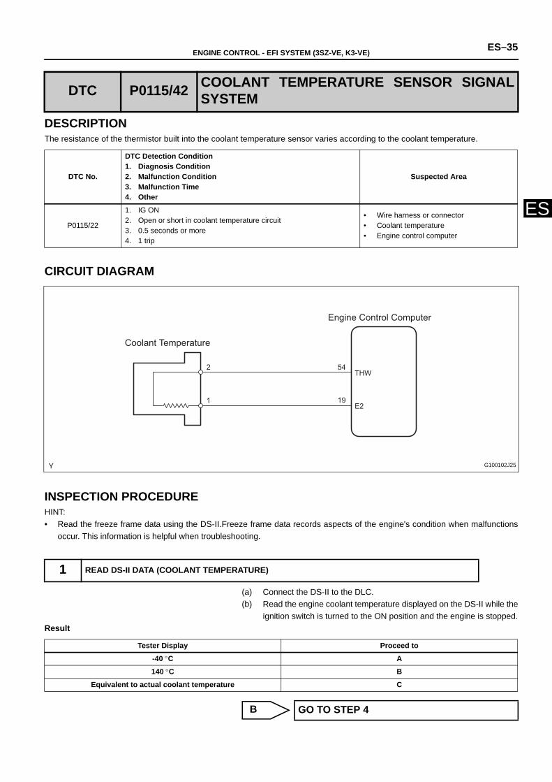
DESCRIPTIONThe resistance of the thermistor built into the coolant temperature sensor varies according to the coolant temperature.
CIRCUIT DIAGRAM
INSPECTION PROCEDUREHINT:• Read the freeze frame data using the DS-II.Freeze frame data records aspects of the engine's condition when malfunctions
occur. This information is helpful when troubleshooting.
(a) Connect the DS-II to the DLC.(b) Read the engine coolant temperature displayed on the DS-II while the
ignition switch is turned to the ON position and the engine is stopped.Result
B
DTC P0115/42 COOLANT TEMPERATURE SENSOR SIGNALSYSTEM
DTC No.
DTC Detection Condition1. Diagnosis Condition2. Malfunction Condition3. Malfunction Time4. Other
Suspected Area
P0115/22
1. IG ON2. Open or short in coolant temperature circuit3. 0.5 seconds or more4. 1 trip
• Wire harness or connector• Coolant temperature• Engine control computer
1 READ DS-II DATA (COOLANT TEMPERATURE)
Engine Control Computer
Coolant Temperature
E21
2THW
54
19
G100102J25
Tester Display Proceed to
-40 °C A
140 °C B
Equivalent to actual coolant temperature C
GO TO STEP 4
ES–36 ENGINE CONTROL - EFI SYSTEM (3SZ-VE, K3-VE)
ES
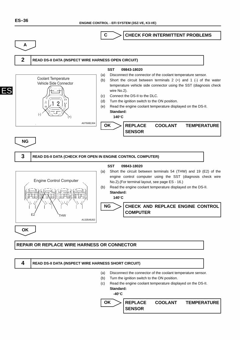
C
A
SST 09843-18020(a) Disconnect the connector of the coolant temperature sensor.(b) Short the circuit between terminals 2 (+) and 1 (-) of the water
temperature vehicle side connector using the SST (diagnosis checkwire No.2).
(c) Connect the DS-II to the DLC.(d) Turn the ignition switch to the ON position.(e) Read the engine coolant temperature displayed on the DS-II.
Standard:140°C
OK
NG
SST 09843-18020(a) Short the circuit between terminals 54 (THW) and 19 (E2) of the
engine control computer using the SST (diagnosis check wireNo.2).(For terminal layout, see page ES - 16.)
(b) Read the engine coolant temperature displayed on the DS-II. Standard:
140°C
NG
OK
(a) Disconnect the connector of the coolant temperature sensor.(b) Turn the ignition switch to the ON position.(c) Read the engine coolant temperature displayed on the DS-II.
Standard:-40°C
OK
CHECK FOR INTERMITTENT PROBLEMS
2 READ DS-II DATA (INSPECT WIRE HARNESS OPEN CIRCUIT)
Coolant Temperature Vehicle Side Connector
(-)(+)
A075082J04 REPLACE COOLANT TEMPERATURESENSOR
3 READ DS-II DATA (CHECK FOR OPEN IN ENGINE CONTROL COMPUTER)
Engine Control Computer
THWE2A133549J02
CHECK AND REPLACE ENGINE CONTROLCOMPUTER
REPAIR OR REPLACE WIRE HARNESS OR CONNECTOR
4 READ DS-II DATA (INSPECT WIRE HARNESS SHORT CIRCUIT)
REPLACE COOLANT TEMPERATURESENSOR

ENGINE CONTROL - EFI SYSTEM (3SZ-VE, K3-VE) ES–37
ES
NG
(a) Disconnect connector B of the engine control computer and theconnector of the coolant temperature sensor.
(b) Using a tester, check whether there is continuity or a short betweenthe vehicle side connector or the engine control computer and thevehicle side connector of the coolant temperature sensor.(Forterminal layout, see page ES - 16.)Standard
NG
OK
5 CHECK WIRE HARNESS AND CONNECTOR (ENGINE CONTROL COMPUTER COOLANTTEMPERATURE)
Engine Control Computer
E.F.I. Coolant Temperature Vehicle Side Connector
(-) (+)
THWE2
A133552J01
Tester Connection (Terminal Symbol)Engine control computer ←→
Coolant temperatureStandard
54(THW) ←→ 2(+)There is continuity and no short
between other terminals and body ground
19(E2) ←→ 1(-) There is continuity, and no short between other terminals
REPAIR OR REPLACE WIRE HARNESS ORCONNECTOR
CHECK AND REPLACE ENGINE CONTROL COMPUTER
ES–38 ENGINE CONTROL - EFI SYSTEM (3SZ-VE, K3-VE)
ES
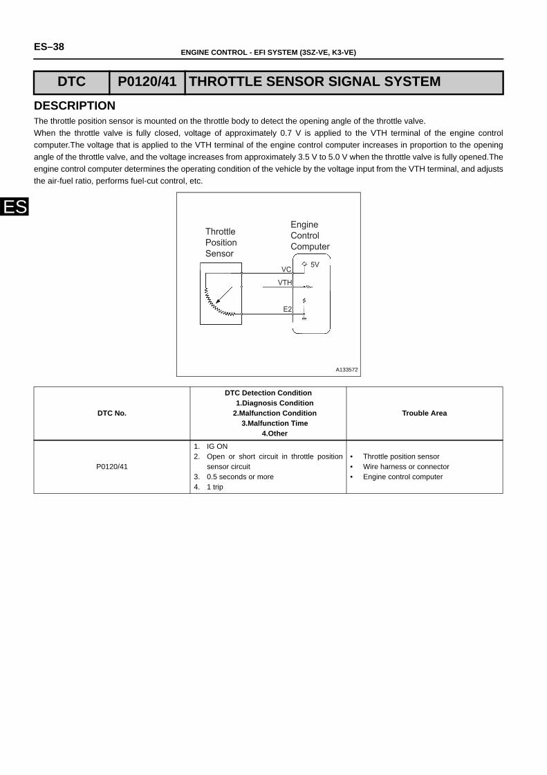
DESCRIPTIONThe throttle position sensor is mounted on the throttle body to detect the opening angle of the throttle valve.When the throttle valve is fully closed, voltage of approximately 0.7 V is applied to the VTH terminal of the engine controlcomputer.The voltage that is applied to the VTH terminal of the engine control computer increases in proportion to the openingangle of the throttle valve, and the voltage increases from approximately 3.5 V to 5.0 V when the throttle valve is fully opened.Theengine control computer determines the operating condition of the vehicle by the voltage input from the VTH terminal, and adjuststhe air-fuel ratio, performs fuel-cut control, etc.
DTC P0120/41 THROTTLE SENSOR SIGNAL SYSTEM
DTC No.
DTC Detection Condition1.Diagnosis Condition
2.Malfunction Condition3.Malfunction Time
4.Other
Trouble Area
P0120/41
1. IG ON2. Open or short circuit in throttle position
sensor circuit3. 0.5 seconds or more4. 1 trip
• Throttle position sensor• Wire harness or connector• Engine control computer
VC
VTH
E2
5V
Throttle Position Sensor
Engine Control Computer
A133572
ENGINE CONTROL - EFI SYSTEM (3SZ-VE, K3-VE) ES–39
ES
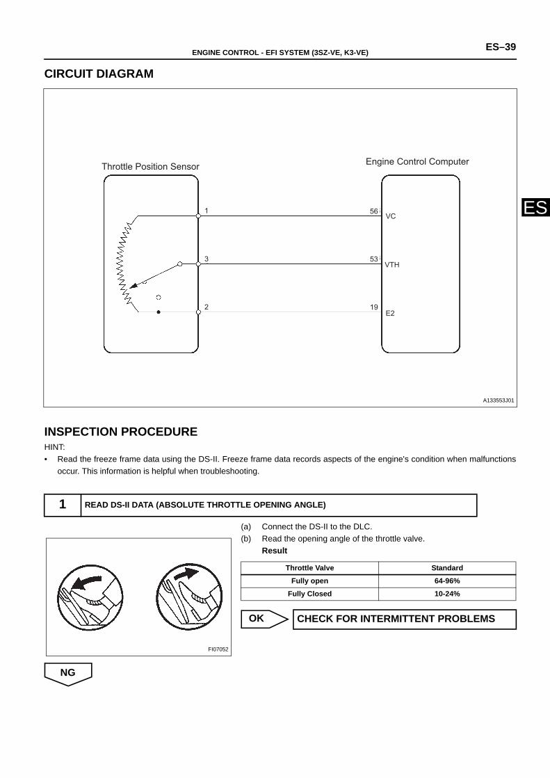
CIRCUIT DIAGRAM
INSPECTION PROCEDUREHINT:• Read the freeze frame data using the DS-II. Freeze frame data records aspects of the engine's condition when malfunctions
occur. This information is helpful when troubleshooting.
(a) Connect the DS-II to the DLC.(b) Read the opening angle of the throttle valve.
Result
OK
NG
1 READ DS-II DATA (ABSOLUTE THROTTLE OPENING ANGLE)
1
3
2
B16
B13
B6
VC
VTH
E2
Throttle Position Sensor Engine Control Computer
56
53
19
A133553J01
FI07052
Throttle Valve Standard
Fully open 64-96%
Fully Closed 10-24%
CHECK FOR INTERMITTENT PROBLEMS
ES–40 ENGINE CONTROL - EFI SYSTEM (3SZ-VE, K3-VE)
ES
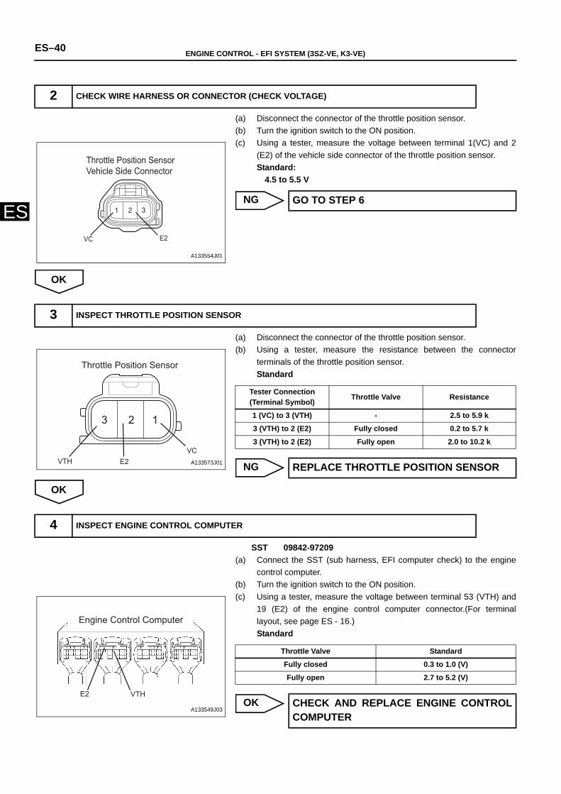
(a) Disconnect the connector of the throttle position sensor.(b) Turn the ignition switch to the ON position.(c) Using a tester, measure the voltage between terminal 1(VC) and 2
(E2) of the vehicle side connector of the throttle position sensor. Standard:
4.5 to 5.5 V
NG
OK
(a) Disconnect the connector of the throttle position sensor.(b) Using a tester, measure the resistance between the connector
terminals of the throttle position sensor.Standard
NG
OK
SST 09842-97209(a) Connect the SST (sub harness, EFI computer check) to the engine
control computer.(b) Turn the ignition switch to the ON position.(c) Using a tester, measure the voltage between terminal 53 (VTH) and
19 (E2) of the engine control computer connector.(For terminallayout, see page ES - 16.)Standard
OK
2 CHECK WIRE HARNESS OR CONNECTOR (CHECK VOLTAGE)
Throttle Position Sensor Vehicle Side Connector
VC E2
A133554J01
GO TO STEP 6
3 INSPECT THROTTLE POSITION SENSOR
123
VTH E2VC
Throttle Position Sensor
A133573J01
Tester Connection (Terminal Symbol) Throttle Valve Resistance
1 (VC) to 3 (VTH) - 2.5 to 5.9 k
3 (VTH) to 2 (E2) Fully closed 0.2 to 5.7 k
3 (VTH) to 2 (E2) Fully open 2.0 to 10.2 k
REPLACE THROTTLE POSITION SENSOR
4 INSPECT ENGINE CONTROL COMPUTER
Engine Control Computer
VTHE2
A133549J03
Throttle Valve Standard
Fully closed 0.3 to 1.0 (V)
Fully open 2.7 to 5.2 (V)
CHECK AND REPLACE ENGINE CONTROLCOMPUTER
ENGINE CONTROL - EFI SYSTEM (3SZ-VE, K3-VE) ES–41
ES
NG
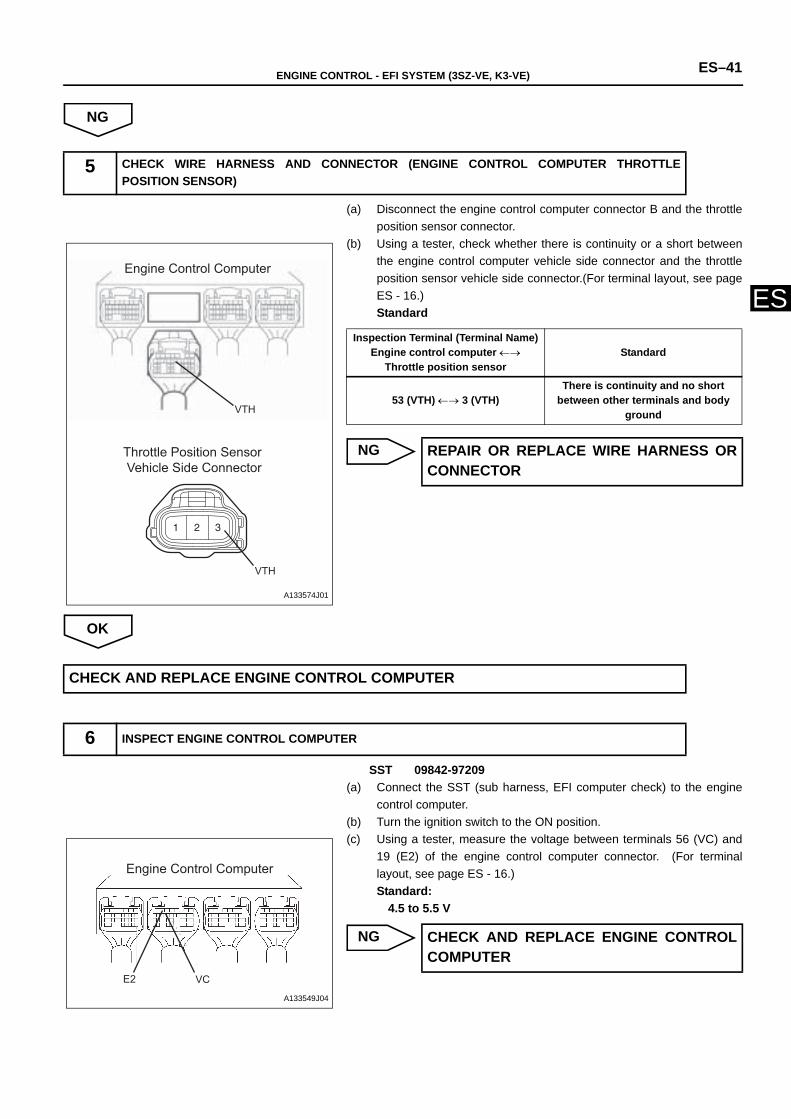
(a) Disconnect the engine control computer connector B and the throttleposition sensor connector.
(b) Using a tester, check whether there is continuity or a short betweenthe engine control computer vehicle side connector and the throttleposition sensor vehicle side connector.(For terminal layout, see pageES - 16.)Standard
NG
OK
SST 09842-97209(a) Connect the SST (sub harness, EFI computer check) to the engine
control computer. (b) Turn the ignition switch to the ON position.(c) Using a tester, measure the voltage between terminals 56 (VC) and
19 (E2) of the engine control computer connector. (For terminallayout, see page ES - 16.)Standard:
4.5 to 5.5 V
NG
5 CHECK WIRE HARNESS AND CONNECTOR (ENGINE CONTROL COMPUTER THROTTLEPOSITION SENSOR)
Engine Control Computer
Throttle Position Sensor Vehicle Side Connector
VTH
VTH
A133574J01
Inspection Terminal (Terminal Name)Engine control computer ←→
Throttle position sensorStandard
53 (VTH) ←→ 3 (VTH)There is continuity and no short
between other terminals and body ground
REPAIR OR REPLACE WIRE HARNESS ORCONNECTOR
CHECK AND REPLACE ENGINE CONTROL COMPUTER
6 INSPECT ENGINE CONTROL COMPUTER
Engine Control Computer
E2 VC
A133549J04
CHECK AND REPLACE ENGINE CONTROLCOMPUTER
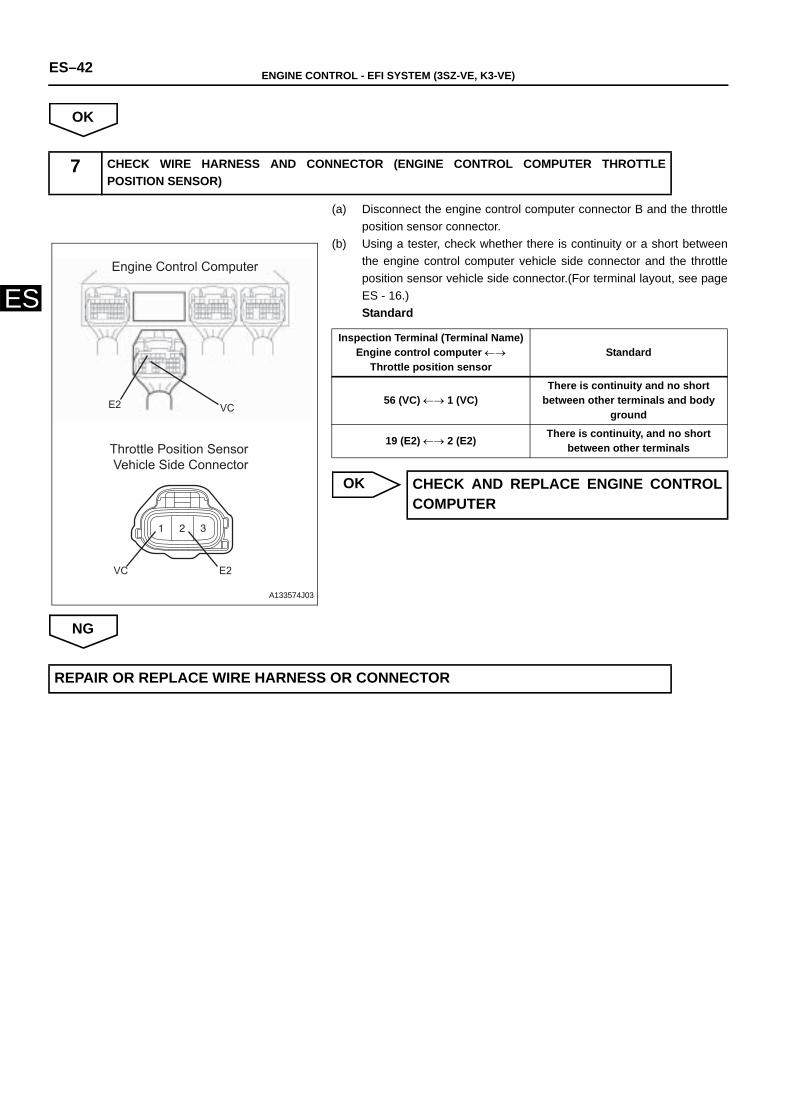
ES–42 ENGINE CONTROL - EFI SYSTEM (3SZ-VE, K3-VE)
ES
OK
(a) Disconnect the engine control computer connector B and the throttleposition sensor connector.
(b) Using a tester, check whether there is continuity or a short betweenthe engine control computer vehicle side connector and the throttleposition sensor vehicle side connector.(For terminal layout, see pageES - 16.)Standard
OK
NG
7 CHECK WIRE HARNESS AND CONNECTOR (ENGINE CONTROL COMPUTER THROTTLEPOSITION SENSOR)
Engine Control Computer
Throttle Position Sensor Vehicle Side Connector
VC
E2VC
E2
A133574J03
Inspection Terminal (Terminal Name)Engine control computer ←→
Throttle position sensorStandard
56 (VC) ←→ 1 (VC)There is continuity and no short
between other terminals and body ground
19 (E2) ←→ 2 (E2) There is continuity, and no short between other terminals
CHECK AND REPLACE ENGINE CONTROLCOMPUTER
REPAIR OR REPLACE WIRE HARNESS OR CONNECTOR
ENGINE CONTROL - EFI SYSTEM (3SZ-VE, K3-VE) ES–43
ES
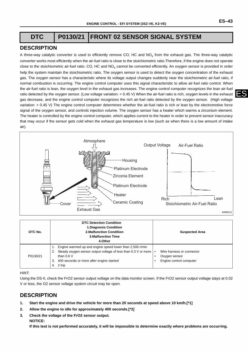
DESCRIPTIONA three-way catalytic converter is used to efficiently remove CO, HC and NOx from the exhaust gas. The three-way catalyticconverter works most efficiently when the air-fuel ratio is close to the stoichiometric ratio.Therefore, if the engine does not operateclose to the stoichiometric air-fuel ratio. CO, HC and NOx cannot be converted efficiently. An oxygen sensor is provided in orderhelp the system maintain the stoichiometric ratio. The oxygen sensor is used to detect the oxygen concentration of the exhaustgas. The oxygen sensor has a characteristic where its voltage output changes suddenly near the stoichiometric air-fuel ratio, ifnormal combustion is occurring. The engine control computer uses this signal characteristic to allow air-fuel ratio control. Whenthe air-fuel ratio is lean, the oxygen level in the exhaust gas increases. The engine control computer recognizes the lean air-fuelratio detected by the oxygen sensor. (Low voltage variation: < 0.45 V) When the air-fuel ratio is rich, oxygen levels in the exhaustgas decrease, and the engine control computer recognizes the rich air-fuel ratio detected by the oxygen sensor. (High voltagevariation: > 0.45 V) The engine control computer determines whether the air-fuel ratio is rich or lean by the electromotive forcesignal of the oxygen sensor, and controls injection volume. The oxygen sensor has a heater which warms a zirconium element.The heater is controlled by the engine control computer, which applies current to the heater in order to prevent sensor inaccuracythat may occur if the sensor gets cold when the exhaust gas temperature is low (such as when there is a low amount of intakeair).
HINT:Using the DS-II, check the FrO2 sensor output voltage on the data monitor screen. If the FrO2 sensor output voltage stays at 0.02V or less, the O2 sensor voltage system circuit may be open.
DESCRIPTION1. Start the engine and drive the vehicle for more than 20 seconds at speed above 10 km/h.[*1]2. Allow the engine to idle for approximately 400 seconds.[*2]3. Check the voltage of the FrO2 sensor output.
NOTICE:If this test is not performed accurately, it will be impossible to determine exactly where problems are occurring.
DTC P0130/21 FRONT 02 SENSOR SIGNAL SYSTEM
DTC No.
DTC Detection Condition1.Diagnosis Condition
2.Malfunction Condition3.Malfunction Time
4.Other
Suspected Area
P0130/21
1. Engine warmed up and engine speed lower than 2,500 r/min2. Steady oxygen sensor output voltage of less than 0.3 V or more
than 0.6 V 3. 400 seconds or more after engine started4. 2 trip
• Wire harness or connector• Oxygen sensor• Engine control computer
Output Voltage
Cover Exhaust Gas
Ceramic Coating
Heater
Platinum Electrode
Zirconia Element
Platinum Electrode
Housing
AtmosphereAir-Fuel Ratio
Rich Lean Stoichiometric Air-Fuel Ratio
A069512
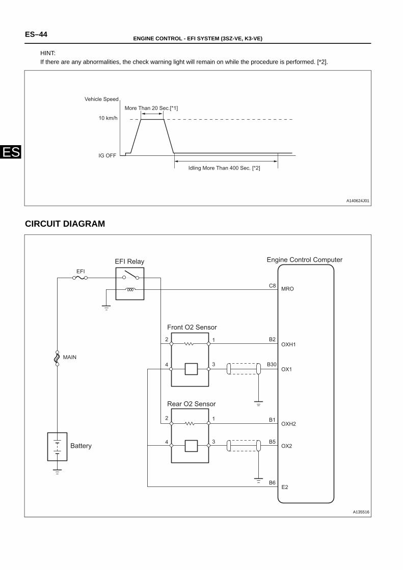
ES–44 ENGINE CONTROL - EFI SYSTEM (3SZ-VE, K3-VE)
ES
HINT:If there are any abnormalities, the check warning light will remain on while the procedure is performed. [*2].
CIRCUIT DIAGRAM
Vehicle Speed
10 km/h
Idling More Than 400 Sec. [*2]
More Than 20 Sec.[*1]
IG OFF
A140624J01
EFI
MAIN
MRO
OXH1
OX1
OX2
OXH2
C8
B2
B30
B5
B1
B6E2
12
34
12
34
Engine Control Computer
Front O2 Sensor
Rear O2 Sensor
EFI Relay
Battery
A135516
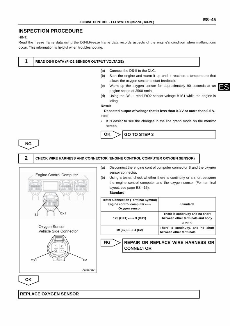
ENGINE CONTROL - EFI SYSTEM (3SZ-VE, K3-VE) ES–45
ES
INSPECTION PROCEDUREHINT:Read the freeze frame data using the DS-II.Freeze frame data records aspects of the engine's condition when malfunctionsoccur. This information is helpful when troubleshooting.
(a) Connect the DS-II to the DLC.(b) Start the engine and warm it up until it reaches a temperature that
allows the oxygen sensor to start feedback.(c) Warm up the oxygen sensor for approximately 90 seconds at an
engine speed of 2500 r/min.(d) Using the DS-II, read FrO2 sensor voltage B1S1 while the engine is
idling. Result:
Repeated output of voltage that is less than 0.3 V or more than 0.6 V. HINT:• It is easier to see the changes in the line graph mode on the monitor
screen.
OK
NG
(a) Disconnect the engine control computer connector B and the oxygensensor connector.
(b) Using a tester, check whether there is continuity or a short betweenthe engine control computer and the oxygen sensor (For terminallayout, see page ES - 16).Standard
NG
OK
1 READ DS-II DATA (FrO2 SENSOR OUTPUT VOLTAGE)
GO TO STEP 3
2 CHECK WIRE HARNESS AND CONNECTOR (ENGINE CONTROL COMPUTER OXYGEN SENSOR)
Engine Control Computer
Oxygen SensorVehicle Side Connector
OX1 E2
E2 OX1
A133576J04
Tester Connection (Terminal Symbol)Engine control computer ←→
Oxygen sensor Standard
123 (OX1) ←→ 3 (OX1)There is continuity and no short
between other terminals and body ground
19 (E2) ←→ 4 (E2) There is continuity, and no shortbetween other terminals
REPAIR OR REPLACE WIRE HARNESS ORCONNECTOR
REPLACE OXYGEN SENSOR
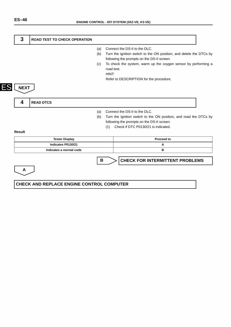
ES–46 ENGINE CONTROL - EFI SYSTEM (3SZ-VE, K3-VE)
ES
(a) Connect the DS-II to the DLC.(b) Turn the ignition switch to the ON position, and delete the DTCs by
following the prompts on the DS-II screen.(c) To check the system, warm up the oxygen sensor by performing a
road test.HINT:Refer to DESCRIPTION for the procedure.
NEXT
(a) Connect the DS-II to the DLC.(b) Turn the ignition switch to the ON position, and read the DTCs by
following the prompts on the DS-II screen.(1) Check if DTC P0130/21 is indicated.
Result
B
A
3 ROAD TEST TO CHECK OPERATION
4 READ DTCS
Tester Display Proceed to
Indicates P0130/21 A
Indicates a normal code B
CHECK FOR INTERMITTENT PROBLEMS
CHECK AND REPLACE ENGINE CONTROL COMPUTER
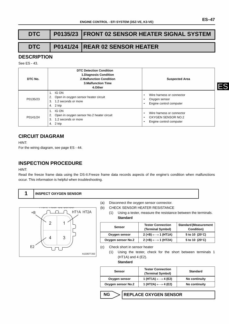
ENGINE CONTROL - EFI SYSTEM (3SZ-VE, K3-VE) ES–47
ES
DESCRIPTIONSee ES - 43.
CIRCUIT DIAGRAMHINT:For the wiring diagram, see page ES - 44.
INSPECTION PROCEDUREHINT:Read the freeze frame data using the DS-II.Freeze frame data records aspects of the engine's condition when malfunctionsoccur. This information is helpful when troubleshooting.
(a) Disconnect the oxygen sensor connector.(b) CHECK SENSOR HEATER RESISTANCE
(1) Using a tester, measure the resistance between the terminals.Standard
(c) Check short in sensor heater (1) Using the tester, check for the short between terminals 1
(HT1A) and 4 (E2).Standard
NG
DTC P0135/23 FRONT 02 SENSOR HEATER SIGNAL SYSTEM
DTC P0141/24 REAR 02 SENSOR HEATER
DTC No.
DTC Detection Condition1.Diagnosis Condition
2.Malfunction Condition3.Malfunction Time
4.Other
Suspected Area
P0135/23
1. IG ON2. Open in oxygen sensor heater circuit3. 1.2 seconds or more4. 2 trip
• Wire harness or connector• Oxygen sensor• Engine control computer
P0141/24
1. IG ON2. Open in oxygen sensor No.2 heater circuit 3. 1.2 seconds or more4. 2 trip
• Wire harness or connector• OXYGEN SENSOR NO.2• Engine control computer
1 INSPECT OXYGEN SENSOR
12
34
Front Rear O2 Sensor+B
E2
HT1A HT2A
A133577J02
Sensor Tester Connection (Terminal Symbol)
Standard (Measurement Condition)
Oxygen sensor 2 (+B) ←→ 1 (HT1A) 5 to 10 (20°C)
Oxygen sensor No.2 2 (+B) ←→ 1 (HT2A) 5 to 10 (20°C)
Sensor Tester Connection (Terminal Symbol) Standard
Oxygen sensor 1 (HT1A) ←→ 4 (E2) No continuity
Oxygen sensor No.2 1 (HT2A) ←→ 4 (E2) No continuity
REPLACE OXYGEN SENSOR
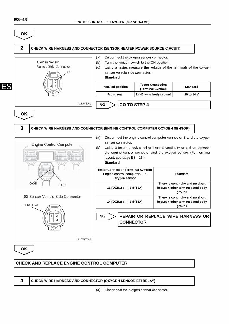
ES–48 ENGINE CONTROL - EFI SYSTEM (3SZ-VE, K3-VE)
ES
OK
(a) Disconnect the oxygen sensor connector.(b) Turn the ignition switch to the ON position.(c) Using a tester, measure the voltage of the terminals of the oxygen
sensor vehicle side connecter.Standard
NG
OK
(a) Disconnect the engine control computer connector B and the oxygensensor connector.
(b) Using a tester, check whether there is continuity or a short betweenthe engine control computer and the oxygen sensor. (For terminallayout, see page ES - 16.)Standard
NG
OK
(a) Disconnect the oxygen sensor connector.
2 CHECK WIRE HARNESS AND CONNECTOR (SENSOR HEATER POWER SOURCE CIRCUIT)
Oxygen Sensor Vehicle Side Connector
+B
A133578J01
Installed position Tester Connection (Terminal Symbol) Standard
Front, rear 2 (+B) ←→ body ground 10 to 14 V
GO TO STEP 4
3 CHECK WIRE HARNESS AND CONNECTOR (ENGINE CONTROL COMPUTER OXYGEN SENSOR)
Engine Control Computer
02 Sensor Vehicle Side Connector
OXH2OXH1
HT1A HT2A
A133576J03
Tester Connection (Terminal Symbol)Engine control computer ←→
Oxygen sensor Standard
15 (OXH1) ←→ 1 (HT1A)There is continuity and no short
between other terminals and body ground
14 (OXH2) ←→ 1 (HT2A)There is continuity and no short
between other terminals and body ground
REPAIR OR REPLACE WIRE HARNESS ORCONNECTOR
CHECK AND REPLACE ENGINE CONTROL COMPUTER
4 CHECK WIRE HARNESS AND CONNECTOR (OXYGEN SENSOR EFI RELAY)
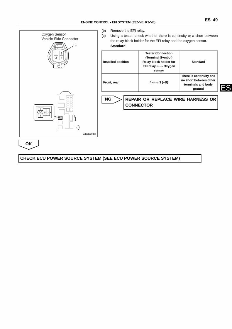
ENGINE CONTROL - EFI SYSTEM (3SZ-VE, K3-VE) ES–49
ES
(b) Remove the EFI relay.(c) Using a tester, check whether there is continuity or a short between
the relay block holder for the EFI relay and the oxygen sensor.Standard
NG
OK
1
25 3
Oxygen Sensor Vehicle Side Connector
+B
A133579J01
Installed position
Tester Connection (Terminal Symbol)
Relay block holder for EFI relay ←→ Oxygen
sensor
Standard
Front, rear 4 ←→ 3 (+B)
There is continuity and no short between other
terminals and body ground
REPAIR OR REPLACE WIRE HARNESS ORCONNECTOR
CHECK ECU POWER SOURCE SYSTEM (SEE ECU POWER SOURCE SYSTEM)
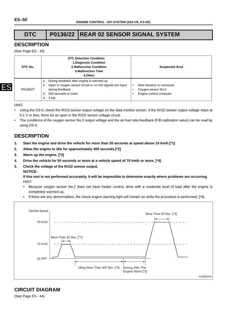
ES–50 ENGINE CONTROL - EFI SYSTEM (3SZ-VE, K3-VE)
ES
DESCRIPTION(See Page ES - 43)
HINT:• Using the DS-II, check the RrO2 sensor output voltage on the data monitor screen. If the RrO2 sensor output voltage stays at
0.1 V or less, there be an open in the RrO2 sensor voltage circuit.• The conditions of the oxygen sensor No.2 output voltage and the air-fuel ratio feedback (F/B calibration value) can be read by
using DS-II.
DESCRIPTION1. Start the engine and drive the vehicle for more than 20 seconds at speed above 10 km/h.[*1]2. Allow the engine to idle for approximately 400 seconds.[*2]3. Warm up the engine. [*3]4. Drive the vehicle for 50 seconds or more at a vehicle speed of 70 km/h or more. [*4]5. Check the voltage of the RrO2 sensor output.
NOTICE:If this test is not performed accurately, it will be impossible to determine exactly where problems are occurring. HINT:• Because oxygen sensor No.2 does not have heater control, drive with a moderate level of load after the engine is
completely warmed up. • If there are any abnormalities, the check engine warning light will remain on while the procedure is performed. [*4].
CIRCUIT DIAGRAM(See Page ES - 44)
DTC P0136/22 REAR 02 SENSOR SIGNAL SYSTEM
DTC No.
DTC Detection Condition1.Diagnosis Condition
2.Malfunction Condition3.Malfunction Time
4.Other
Suspected Area
P0136/27
1. During feedback after engine is warmed up 2. Open in oxygen sensor circuit or no rich signals are input
during feedback 3. 500 seconds or more4. 2 trip
• Wire harness or connector• Oxygen sensor No.2• Engine control computer
Vehicle SpeedMore Than 50 Sec. [*4]
70 km/h
10 km/h
IG OFF
Idling More Than 400 Sec. [*2] Driving With The Engine Warm [*3]
More Than 20 Sec. [*1]
A140625J01
ENGINE CONTROL - EFI SYSTEM (3SZ-VE, K3-VE) ES–51
ES
INSPECTION PROCEDUREHINT:Read the freeze frame data using the DS-II.Freeze frame data records aspects of the engine's condition when malfunctionsoccur. This information is helpful whnen troubleshooting.
(a) Connect the DS-II to the DLC.(b) Turn the ignition switch to the ON position, and delete the DTCs by
following the prompts on the DS-II screen.(See page ES - 8.)(c) Perform a road test. (d) Check for DTCs following the prompts on the DS-II screen. (See
page ES - 8.)(1) Check if DTC P0136/27 is indicated.
Result
HINT:If DTC P0136/27 and other DTCs are output at the same time,check the other codes first.
B
C
A
1 READ DTCs
Tester Display Proceed to
Indicates P0136/27 A
Indicates P036/27 and other codes B
Indicates a normal code C
GO TO RELEVANT DTC CHART
CHECK FOR INTERMITTENT PROBLEMS
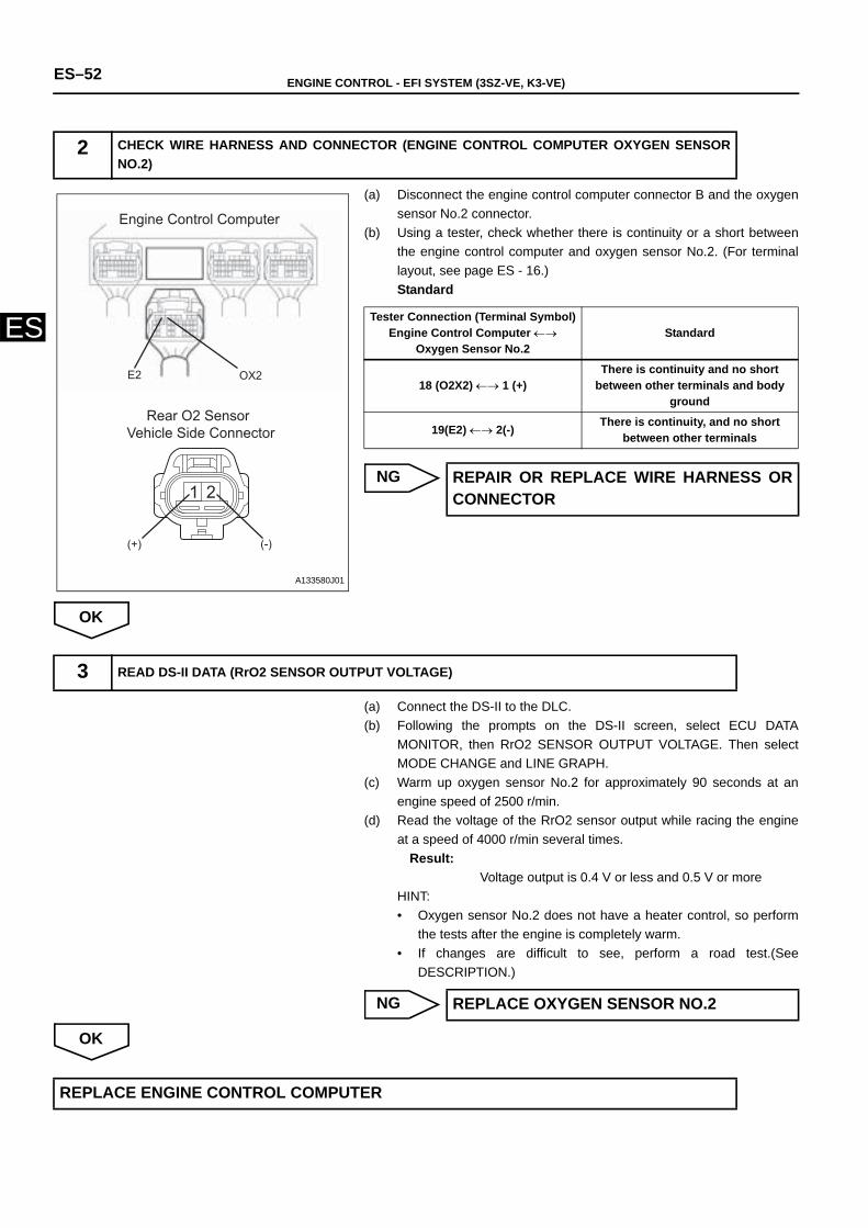
ES–52 ENGINE CONTROL - EFI SYSTEM (3SZ-VE, K3-VE)
ES
(a) Disconnect the engine control computer connector B and the oxygensensor No.2 connector.
(b) Using a tester, check whether there is continuity or a short betweenthe engine control computer and oxygen sensor No.2. (For terminallayout, see page ES - 16.)Standard
NG
OK
(a) Connect the DS-II to the DLC.(b) Following the prompts on the DS-II screen, select ECU DATA
MONITOR, then RrO2 SENSOR OUTPUT VOLTAGE. Then selectMODE CHANGE and LINE GRAPH.
(c) Warm up oxygen sensor No.2 for approximately 90 seconds at anengine speed of 2500 r/min.
(d) Read the voltage of the RrO2 sensor output while racing the engineat a speed of 4000 r/min several times.
Result:Voltage output is 0.4 V or less and 0.5 V or more
HINT:• Oxygen sensor No.2 does not have a heater control, so perform
the tests after the engine is completely warm. • If changes are difficult to see, perform a road test.(See
DESCRIPTION.)
NG
OK
2 CHECK WIRE HARNESS AND CONNECTOR (ENGINE CONTROL COMPUTER OXYGEN SENSORNO.2)
1 2
Engine Control Computer
Rear O2 SensorVehicle Side Connector
OX2E2
(+) (-)
A133580J01
Tester Connection (Terminal Symbol)Engine Control Computer ←→
Oxygen Sensor No.2Standard
18 (O2X2) ←→ 1 (+)There is continuity and no short
between other terminals and body ground
19(E2) ←→ 2(-) There is continuity, and no short between other terminals
REPAIR OR REPLACE WIRE HARNESS ORCONNECTOR
3 READ DS-II DATA (RrO2 SENSOR OUTPUT VOLTAGE)
REPLACE OXYGEN SENSOR NO.2
REPLACE ENGINE CONTROL COMPUTER
ENGINE CONTROL - EFI SYSTEM (3SZ-VE, K3-VE) ES–53
ES
DESCRIPTIONThere are two types of air-fuel ratio corrections. One is the normal operating air-fuel ratio correction (air-fuel ratio F/B). The otheris the memory air-fuel ratio correction (air-fuel ratio F/B learned). Air-fuel ratio F/B is the air-fuel ratio correction that is used tomaintain a stoichiometric ratio. The oxygen sensors send signals to the engine control computer indicating whether the currentair-fuel ratio is rich or lean comparing to the stoichiometric ratio. When the signal indicates that the condition is rich the injectionvolume is decreased. When the signal indicates that the condition is lean the injection volume is increased. Air-fuel ratio F/Blearned value refers to a value that shows the air-fuel ratio F/B value over a long period of time. Because of differences specific toeach engine (such as differences caused by wear over time and changes in the operating environment) this air-fuel ratio F/Blearned value varies from a central value.If either the air-fuel ratio F/B value or the air-fuel ratio F/B learned value exceeds acertain value and becomes lean or rich, the engine control computer illuminates the check warning light.
HINT:If the total of the air-fuel F/B value and the air-fuel F/B learned value is within 25%, the system is normal.
CIRCUIT DIAGRAMSee Page ES - 44.
INSPECTION PROCEDUREHINT:• Check if the engine has stopped in the past because of a fuel cut.If so, the DTC P0171/25 may be recorded.• Read the freeze frame data using the DS-II.Freeze frame data records aspects of the engine's condition when malfunctions
occur. This information is helpful when troubleshooting.
HINT:For inspection procedures, see page EC - 1.
NG
DTC P0171/25 FUEL SYSTEM (LEAN MALFUNCTION)
DTC P0172/26 FUEL SYSTEM (RICH MALFUNCTION)
DTC No.
DTC Detection Condition1.Diagnosis Condition
2.Malfunction Condition3.Malfunction Time
4.Other
Suspected Area
P0171/25
1. While operating the vehicle at 70 km/h with the engine warm, during a normal air-fuel ratio F/B
2. Fuel trim is corrected heavily on the increase side (approx.+ 40 %)
3. 60 seconds or more4. 2 trip
• Intake system• Fuel system• Ignition system • Wire harness or connector• Oxygen sensor• Engine control computer• Gas leakage from exhaust system
P0172/26
1. While operating the vehicle at 70 km/h with the engine warm, during a normal air-fuel ratio F/B
2. Fuel trim is corrected heavily on the decrease side (approx.+ -35%)
3. 60 seconds or more4. 2 trip
• Intake system• Fuel system• Ignition system • Wire harness or connector• Oxygen sensor• Engine control computer• Gas leakage from exhaust system
1 INSPECT EMISSION CONTROL SYSTEM
REPAIR OR REPLACE EMISSION CONTROLSYSTEM
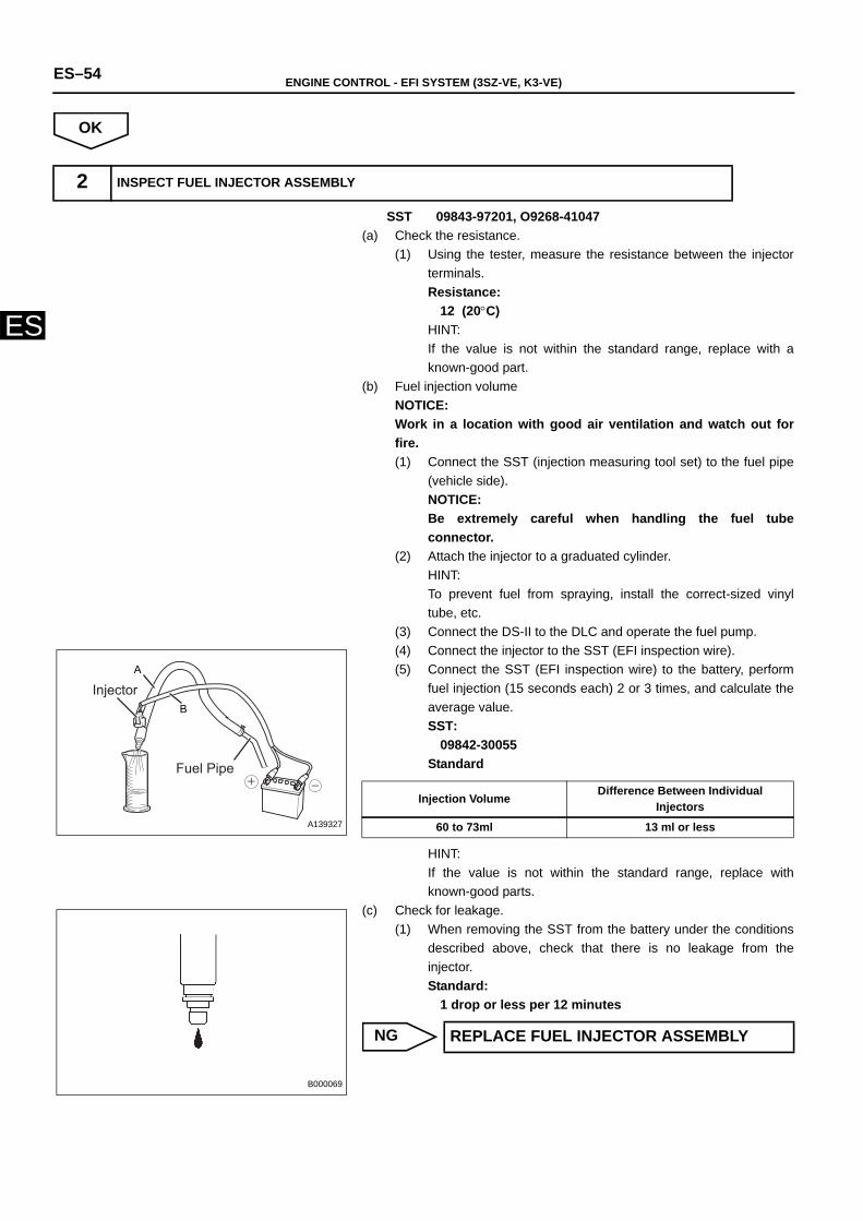
ES–54 ENGINE CONTROL - EFI SYSTEM (3SZ-VE, K3-VE)
ES
OK
SST 09843-97201, O9268-41047(a) Check the resistance.
(1) Using the tester, measure the resistance between the injectorterminals.Resistance:
12 (20°C)HINT:If the value is not within the standard range, replace with aknown-good part.
(b) Fuel injection volumeNOTICE:Work in a location with good air ventilation and watch out forfire.(1) Connect the SST (injection measuring tool set) to the fuel pipe
(vehicle side).NOTICE:Be extremely careful when handling the fuel tubeconnector.
(2) Attach the injector to a graduated cylinder.HINT:To prevent fuel from spraying, install the correct-sized vinyltube, etc.
(3) Connect the DS-II to the DLC and operate the fuel pump.(4) Connect the injector to the SST (EFI inspection wire).(5) Connect the SST (EFI inspection wire) to the battery, perform
fuel injection (15 seconds each) 2 or 3 times, and calculate theaverage value.SST:
09842-30055Standard
HINT:If the value is not within the standard range, replace withknown-good parts.
(c) Check for leakage.(1) When removing the SST from the battery under the conditions
described above, check that there is no leakage from theinjector.Standard:
1 drop or less per 12 minutes
NG
2 INSPECT FUEL INJECTOR ASSEMBLY
A
BInjector
Fuel Pipe
A139327
Injection Volume Difference Between Individual Injectors
60 to 73ml 13 ml or less
B000069
REPLACE FUEL INJECTOR ASSEMBLY
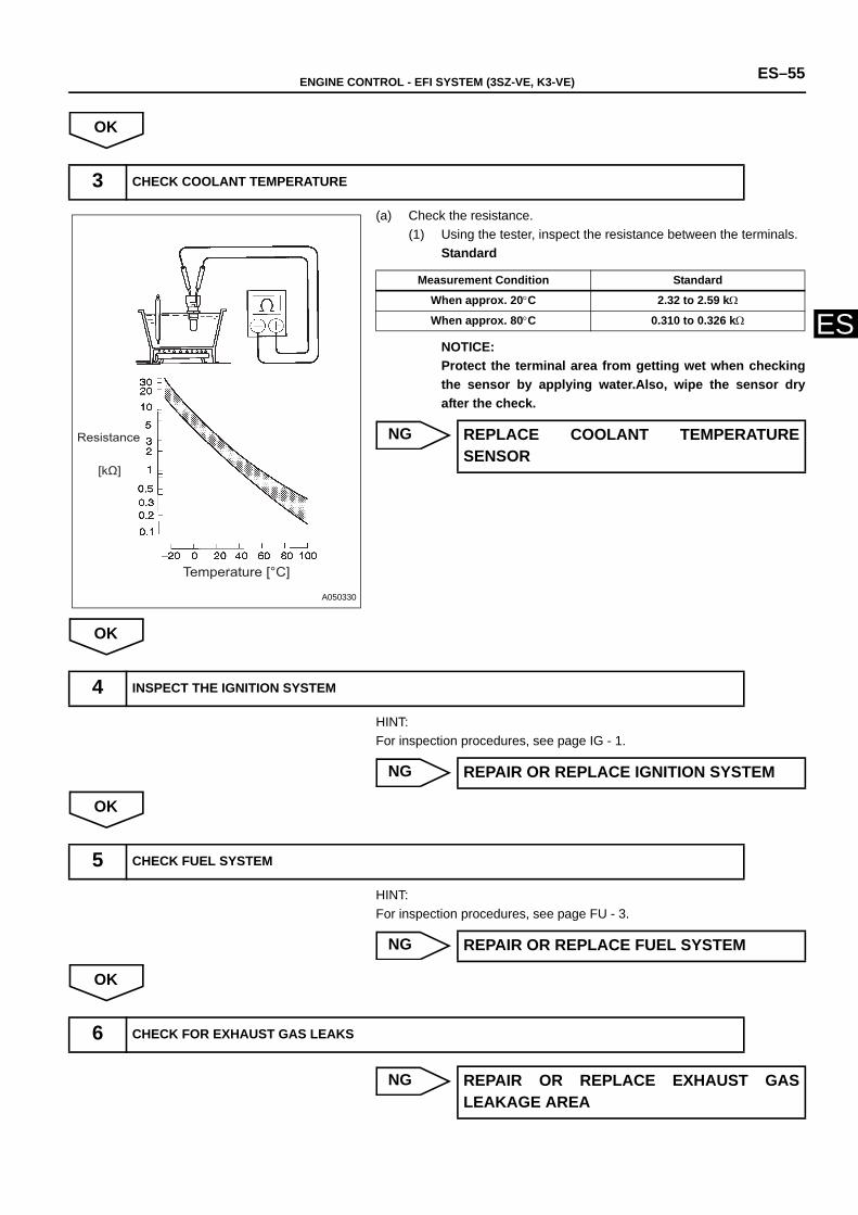
ENGINE CONTROL - EFI SYSTEM (3SZ-VE, K3-VE) ES–55
ES
OK
(a) Check the resistance.(1) Using the tester, inspect the resistance between the terminals.
Standard
NOTICE:Protect the terminal area from getting wet when checkingthe sensor by applying water.Also, wipe the sensor dryafter the check.
NG
OK
HINT:For inspection procedures, see page IG - 1.
NG
OK
HINT:For inspection procedures, see page FU - 3.
NG
OK
NG
3 CHECK COOLANT TEMPERATURE
Temperature [°C]
Resistance
[kΩ]
A050330
Measurement Condition Standard
When approx. 20°C 2.32 to 2.59 kΩ
When approx. 80°C 0.310 to 0.326 kΩ
REPLACE COOLANT TEMPERATURESENSOR
4 INSPECT THE IGNITION SYSTEM
REPAIR OR REPLACE IGNITION SYSTEM
5 CHECK FUEL SYSTEM
REPAIR OR REPLACE FUEL SYSTEM
6 CHECK FOR EXHAUST GAS LEAKS
REPAIR OR REPLACE EXHAUST GASLEAKAGE AREA
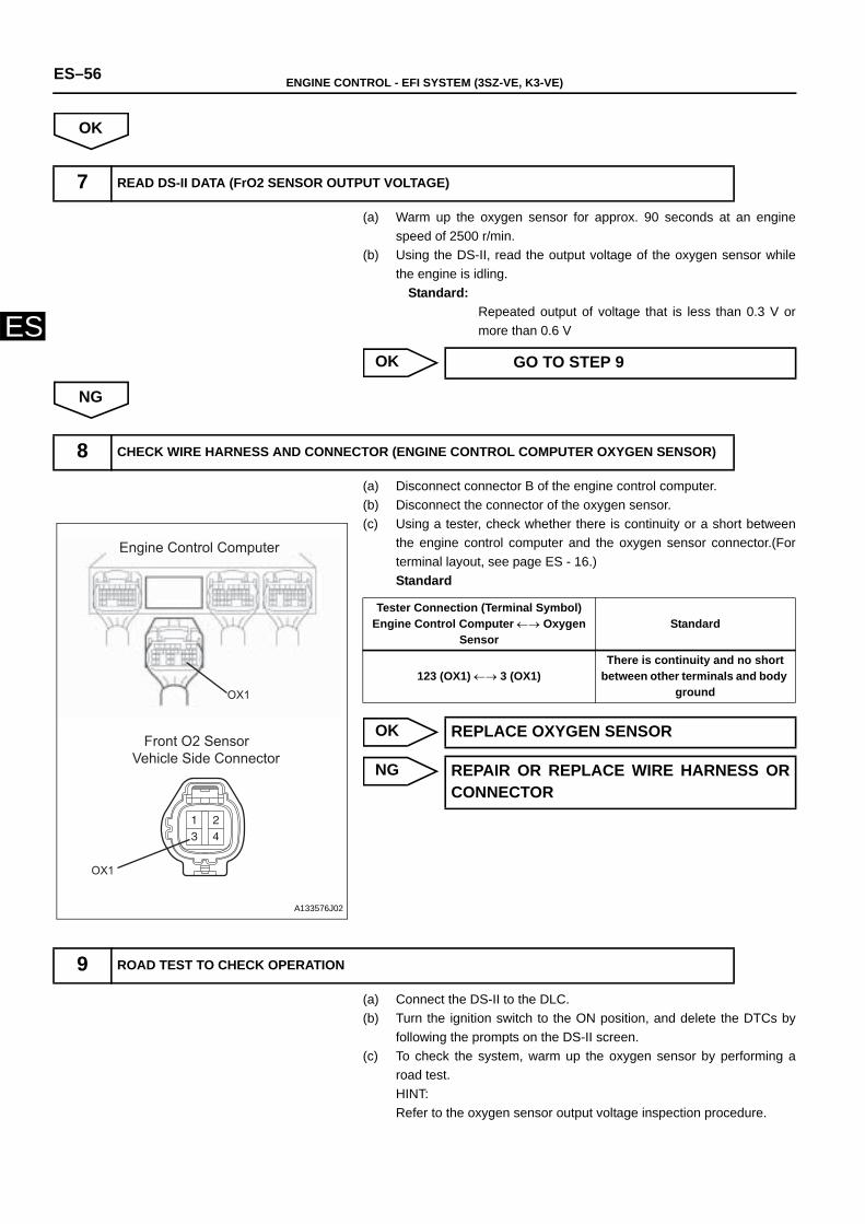
ES–56 ENGINE CONTROL - EFI SYSTEM (3SZ-VE, K3-VE)
ES
OK
(a) Warm up the oxygen sensor for approx. 90 seconds at an enginespeed of 2500 r/min.
(b) Using the DS-II, read the output voltage of the oxygen sensor whilethe engine is idling.
Standard:Repeated output of voltage that is less than 0.3 V ormore than 0.6 V
OK
NG
(a) Disconnect connector B of the engine control computer.(b) Disconnect the connector of the oxygen sensor.(c) Using a tester, check whether there is continuity or a short between
the engine control computer and the oxygen sensor connector.(Forterminal layout, see page ES - 16.)Standard
OK
NG
(a) Connect the DS-II to the DLC.(b) Turn the ignition switch to the ON position, and delete the DTCs by
following the prompts on the DS-II screen.(c) To check the system, warm up the oxygen sensor by performing a
road test.HINT:Refer to the oxygen sensor output voltage inspection procedure.
7 READ DS-II DATA (FrO2 SENSOR OUTPUT VOLTAGE)
GO TO STEP 9
8 CHECK WIRE HARNESS AND CONNECTOR (ENGINE CONTROL COMPUTER OXYGEN SENSOR)
Engine Control Computer
Front O2 SensorVehicle Side Connector
OX1
OX1
A133576J02
Tester Connection (Terminal Symbol)Engine Control Computer ←→ Oxygen
Sensor Standard
123 (OX1) ←→ 3 (OX1)There is continuity and no short
between other terminals and body ground
REPLACE OXYGEN SENSOR
REPAIR OR REPLACE WIRE HARNESS ORCONNECTOR
9 ROAD TEST TO CHECK OPERATION
ENGINE CONTROL - EFI SYSTEM (3SZ-VE, K3-VE) ES–57
ES
GO
(a) Connect the DS-II to the DLC.(b) Turn the ignition switch to the ON position, and read the DTC by
following the prompts on the DS-II screen.(1) Check if DTC P0171/25 is detected.
Result
B
A
10 READ DTCs
A B
P0171/25 is not output again P0171/25 is output again
CHECK AND REPLACE ENGINE CONTROLCOMPUTER
CHECK FOR INTERMITTENT PROBLEMS
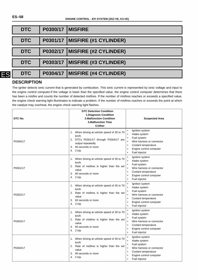
ES–58 ENGINE CONTROL - EFI SYSTEM (3SZ-VE, K3-VE)
ESDESCRIPTIONThe igniter detects ionic current that is generated by combustion. This ionic current is represented by ionic voltage and input tothe engine control computer.If the voltage is lower than the specified value, the engine control computer determines that therehas been a misfire and counts the number of detected misfires. If the number of misfires reaches or exceeds a specified value,the engine check warning light illuminates to indicate a problem. If the number of misfires reaches or exceeds the point at whichthe catalyst may overheat, the engine check warning light flashes.
DTC P0300/17 MISFIRE
DTC P0301/17 MISFIRE (#1 CYLINDER)
DTC P0302/17 MISFIRE (#2 CYLINDER)
DTC P0303/17 MISFIRE (#3 CYLINDER)
DTC P0304/17 MISFIRE (#4 CYLINDER)
DTC No.
DTC Detection Condition1.Diagnosis Condition
2.Malfunction Condition3.Malfunction Time
4.Other
Suspected Area
P0300/17
1. When driving at vehicle speed of 30 to 70km/h
2. DTCs P0301/17 through P0304/17 areoutput repeatedly
3. 60 seconds or more4. 2 trip
• Ignition system • Intake system• Fuel system• Wire harness or connector• Coolant temperature• Engine control computer• Fuel injector
P0301/17
1. When driving at vehicle speed of 30 to 70km/h
2. Rate of misfires is higher than the setvalue
3. 60 seconds or more4. 2 trip
• Ignition system • Intake system• Fuel system• Wire harness or connector• Coolant temperature• Engine control computer• Fuel injector
P0302/17
1. When driving at vehicle speed of 30 to 70km/h
2. Rate of misfires is higher than the setvalue
3. 60 seconds or more4. 2 trip
• Ignition system • Intake system• Fuel system• Wire harness or connector• Coolant temperature• Engine control computer• Fuel injector
P0303/17
1. When driving at vehicle speed of 30 to 70km/h
2. Rate of misfires is higher than the setvalue
3. 60 seconds or more4. 2 trip
• Ignition system • Intake system• Fuel system• Wire harness or connector• Coolant temperature• Engine control computer• Fuel injector
P0304/17
1. When driving at vehicle speed of 30 to 70km/h
2. Rate of misfires is higher than the setvalue
3. 60 seconds or more4. 2 trip
• Ignition system • Intake system• Fuel system• Wire harness or connector• Coolant temperature• Engine control computer• Fuel injector
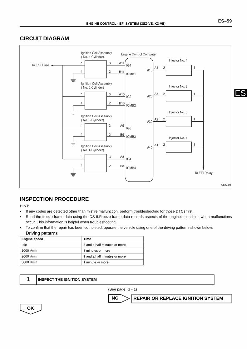
ENGINE CONTROL - EFI SYSTEM (3SZ-VE, K3-VE) ES–59
ES
CIRCUIT DIAGRAM
INSPECTION PROCEDUREHINT:• If any codes are detected other than misfire malfunction, perform troubleshooting for those DTCs first.• Read the freeze frame data using the DS-II.Freeze frame data records aspects of the engine's condition when malfunctions
occur. This information is helpful when troubleshooting.• To confirm that the repair has been completed, operate the vehicle using one of the driving patterns shown below.
Driving patterns
(See page IG - 1)
NG
OK
Engine speed Time
Idle 3 and a half minutes or more
1000 r/min 3 minutes or more
2000 r/min 1 and a half minutes or more
3000 r/min 1 minute or more
1 INSPECT THE IGNITION SYSTEM
IG1
ICMB1
ICMB2
ICMB3
ICMB4
IG2
IG3
IG4
A11
B11
B10
A10
A9
B9
A8
B8
3
2
2
2
2
3
3
3
1
4
1
4
1
4
1
4
2
2
2
2
1
1
1
1
#10
#20
#30
#40
A4
A3
A2
A1
Engine Control Computer
Injector No. 1
Injector No. 2
Injector No. 3
Injector No. 4
To EFI Relay
Ignition Coil Assembly ( No. 4 Cylinder)
Ignition Coil Assembly ( No. 3 Cylinder)
Ignition Coil Assembly ( No. 2 Cylinder)
To E/G Fuse
Ignition Coil Assembly ( No. 1 Cylinder)
A135528
REPAIR OR REPLACE IGNITION SYSTEM
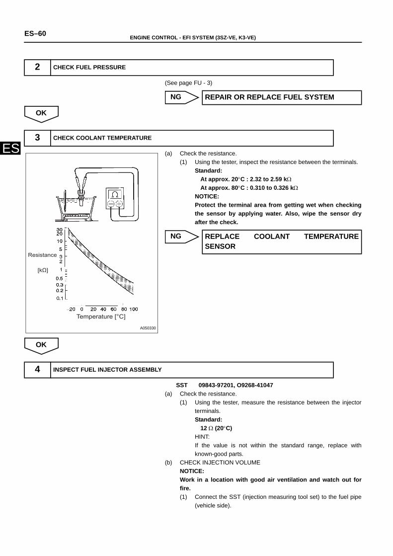
ES–60 ENGINE CONTROL - EFI SYSTEM (3SZ-VE, K3-VE)
ES
(See page FU - 3)
NG
OK
(a) Check the resistance.(1) Using the tester, inspect the resistance between the terminals.
Standard:At approx. 20°C : 2.32 to 2.59 kΩAt approx. 80°C : 0.310 to 0.326 kΩ
NOTICE:Protect the terminal area from getting wet when checkingthe sensor by applying water. Also, wipe the sensor dryafter the check.
NG
OK
SST 09843-97201, O9268-41047(a) Check the resistance.
(1) Using the tester, measure the resistance between the injectorterminals.Standard:
12 Ω (20°C)HINT:If the value is not within the standard range, replace withknown-good parts.
(b) CHECK INJECTION VOLUMENOTICE:Work in a location with good air ventilation and watch out forfire.(1) Connect the SST (injection measuring tool set) to the fuel pipe
(vehicle side).
2 CHECK FUEL PRESSURE
REPAIR OR REPLACE FUEL SYSTEM
3 CHECK COOLANT TEMPERATURE
Temperature [°C]
Resistance
[kΩ]
A050330
REPLACE COOLANT TEMPERATURESENSOR
4 INSPECT FUEL INJECTOR ASSEMBLY
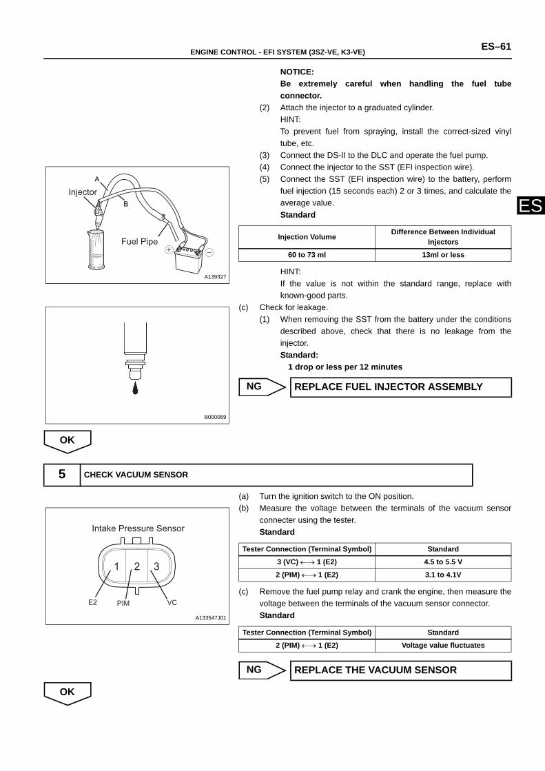
ENGINE CONTROL - EFI SYSTEM (3SZ-VE, K3-VE) ES–61
ES
NOTICE:Be extremely careful when handling the fuel tubeconnector.
(2) Attach the injector to a graduated cylinder.HINT:To prevent fuel from spraying, install the correct-sized vinyltube, etc.
(3) Connect the DS-II to the DLC and operate the fuel pump.(4) Connect the injector to the SST (EFI inspection wire).(5) Connect the SST (EFI inspection wire) to the battery, perform
fuel injection (15 seconds each) 2 or 3 times, and calculate theaverage value.Standard
HINT:If the value is not within the standard range, replace withknown-good parts.
(c) Check for leakage.(1) When removing the SST from the battery under the conditions
described above, check that there is no leakage from theinjector.Standard:
1 drop or less per 12 minutes
NG
OK
(a) Turn the ignition switch to the ON position.(b) Measure the voltage between the terminals of the vacuum sensor
connecter using the tester.Standard
(c) Remove the fuel pump relay and crank the engine, then measure thevoltage between the terminals of the vacuum sensor connector.Standard
NG
OK
A
BInjector
Fuel Pipe
A139327
Injection Volume Difference Between Individual Injectors
60 to 73 ml 13ml or less
B000069
REPLACE FUEL INJECTOR ASSEMBLY
5 CHECK VACUUM SENSOR
1 2 3
Intake Pressure Sensor
E2 PIM VC
A133547J01
Tester Connection (Terminal Symbol) Standard
3 (VC) ←→ 1 (E2) 4.5 to 5.5 V
2 (PIM) ←→ 1 (E2) 3.1 to 4.1V
Tester Connection (Terminal Symbol) Standard
2 (PIM) ←→ 1 (E2) Voltage value fluctuates
REPLACE THE VACUUM SENSOR
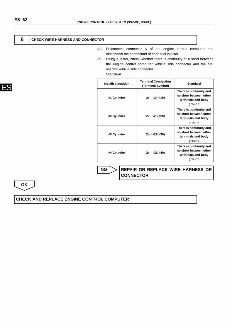
ES–62 ENGINE CONTROL - EFI SYSTEM (3SZ-VE, K3-VE)
ES
(a) Disconnect connector A of the engine control computer anddisconnect the connectors of each fuel injector.
(b) Using a tester, check whether there is continuity or a short betweenthe engine control computer vehicle side connector and the fuelinjector vehicle side connector.Standard
NG
OK
6 CHECK WIRE HARNESS AND CONNECTOR
Installed position Terminal Connection (Terminal Symbol) Standard
#1 Cylinder 2←→24(#10)
There is continuity and no short between other
terminals and body ground
#2 Cylinder 2←→23(#20)
There is continuity and no short between other
terminals and body ground
#3 Cylinder 2←→22(#30)
There is continuity and no short between other
terminals and body ground
#4 Cylinder 2←→21(#40)
There is continuity and no short between other
terminals and body ground
REPAIR OR REPLACE WIRE HARNESS ORCONNECTOR
CHECK AND REPLACE ENGINE CONTROL COMPUTER
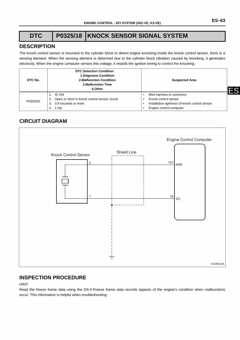
ENGINE CONTROL - EFI SYSTEM (3SZ-VE, K3-VE) ES–63
ES
DESCRIPTIONThe knock control sensor is mounted to the cylinder block to detect engine knocking.Inside the knock control sensor, there is asensing element. When the sensing element is deformed due to the cylinder block vibration caused by knocking, it generateselectricity. When the engine computer senses this voltage, it retards the ignition timing to control the knocking.
CIRCUIT DIAGRAM
INSPECTION PROCEDUREHINT:Read the freeze frame data using the DS-II.Freeze frame data records aspects of the engine's condition when malfunctionsoccur. This information is helpful when troubleshooting.
DTC P0325/18 KNOCK SENSOR SIGNAL SYSTEM
DTC No.
DTC Detection Condition1.Diagnosis Condition
2.Malfunction Condition3.Malfunction Time
4.Other
Suspected Area
P0325/52
1. IG ON2. Open or short in knock control sensor circuit3. 0.9 seconds or more4. 1 trip
• Wire harness or connector• Knock control sensor• Installation tightness of knock control sensor• Engine control computer
2
1
KNK
E2
Knock Control Sensor Shield Line
Engine Control Computer
121
19
A133581J01
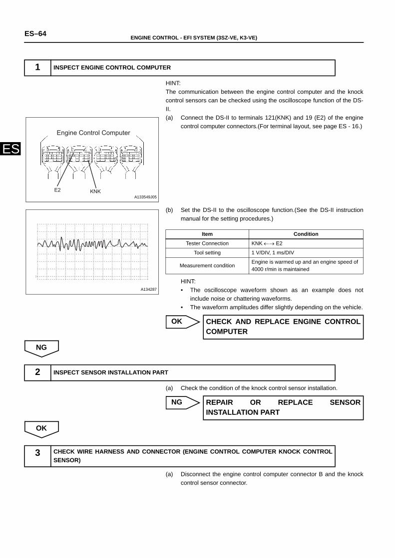
ES–64 ENGINE CONTROL - EFI SYSTEM (3SZ-VE, K3-VE)
ES
HINT:The communication between the engine control computer and the knockcontrol sensors can be checked using the oscilloscope function of the DS-II.(a) Connect the DS-II to terminals 121(KNK) and 19 (E2) of the engine
control computer connectors.(For terminal layout, see page ES - 16.)
(b) Set the DS-II to the oscilloscope function.(See the DS-II instructionmanual for the setting procedures.)
HINT:• The oscilloscope waveform shown as an example does not
include noise or chattering waveforms.• The waveform amplitudes differ slightly depending on the vehicle.
OK
NG
(a) Check the condition of the knock control sensor installation.
NG
OK
(a) Disconnect the engine control computer connector B and the knockcontrol sensor connector.
1 INSPECT ENGINE CONTROL COMPUTER
Engine Control Computer
KNKE2A133549J05
A134287
Item Condition
Tester Connection KNK ←→ E2
Tool setting 1 V/DIV, 1 ms/DIV
Measurement conditionEngine is warmed up and an engine speed of 4000 r/min is maintained
CHECK AND REPLACE ENGINE CONTROLCOMPUTER
2 INSPECT SENSOR INSTALLATION PART
REPAIR OR REPLACE SENSORINSTALLATION PART
3 CHECK WIRE HARNESS AND CONNECTOR (ENGINE CONTROL COMPUTER KNOCK CONTROLSENSOR)
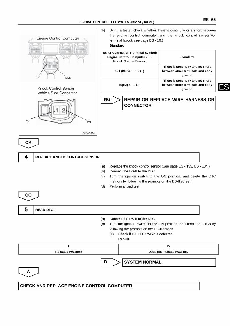
ENGINE CONTROL - EFI SYSTEM (3SZ-VE, K3-VE) ES–65
ES
(b) Using a tester, check whether there is continuity or a short betweenthe engine control computer and the knock control sensor(Forterminal layout, see page ES - 16.)Standard
NG
OK
(a) Replace the knock control sensor.(See page ES - 133, ES - 134.)(b) Connect the DS-II to the DLC.(c) Turn the ignition switch to the ON position, and delete the DTC
memory by following the prompts on the DS-II screen.(d) Perform a road test.
GO
(a) Connect the DS-II to the DLC.(b) Turn the ignition switch to the ON position, and read the DTCs by
following the prompts on the DS-II screen.(1) Check if DTC P0325/52 is detected.
Result
B
A
Engine Control Computer
Knock Control SensorVehicle Side Connector
E2 KNK
(-) (+)
A133582J01
Tester Connection (Terminal Symbol)Engine Control Computer ←→
Knock Control Sensor Standard
121 (KNK) ←→ 2 (+)There is continuity and no short
between other terminals and body ground
19(E2) ←→ 1(-)There is continuity and no short
between other terminals and body ground
REPAIR OR REPLACE WIRE HARNESS ORCONNECTOR
4 REPLACE KNOCK CONTROL SENSOR
5 READ DTCs
A B
Indicates P0325/52 Does not indicate P0325/52
SYSTEM NORMAL
CHECK AND REPLACE ENGINE CONTROL COMPUTER
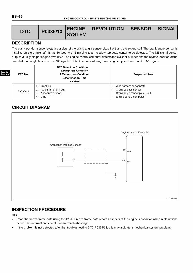
ES–66 ENGINE CONTROL - EFI SYSTEM (3SZ-VE, K3-VE)
ES
DESCRIPTIONThe crank position sensor system consists of the crank angle sensor plate No.1 and the pickup coil. The crank angle sensor isinstalled on the crankshaft. It has 30 teeth with 6 missing teeth to allow top dead center to be detected. The NE signal sensoroutputs 30 signals per engine revolution.The engine control computer detects the cylinder number and the relative position of thecamshaft and angle based on the N2 signal. It detects crankshaft angle and engine speed based on the N1 signal.
CIRCUIT DIAGRAM
INSPECTION PROCEDUREHINT:• Read the freeze frame data using the DS-II. Freeze frame data records aspects of the engine's condition when malfunctions
occur. This information is helpful when troubleshooting.• If the problem is not detected after first troubleshooting DTC P0335/13, this may indicate a mechanical system problem.
DTC P0335/13 ENGINE REVOLUTION SENSOR SIGNALSYSTEM
DTC No.
DTC Detection Condition1.Diagnosis Condition
2.Malfunction Condition3.Malfunction Time
4.Other
Suspected Area
P0335/13
1. Cranking2. N1 signal is not input3. 2 seconds or more4. 1 trip
• Wire harness or connector• Crank position sensor• Crank angle sensor plate No.1 • Engine control computer
Crankshaft Position Sensor
Engine Control Computer
1
2
59
128
N1+
N1-
A133583J02
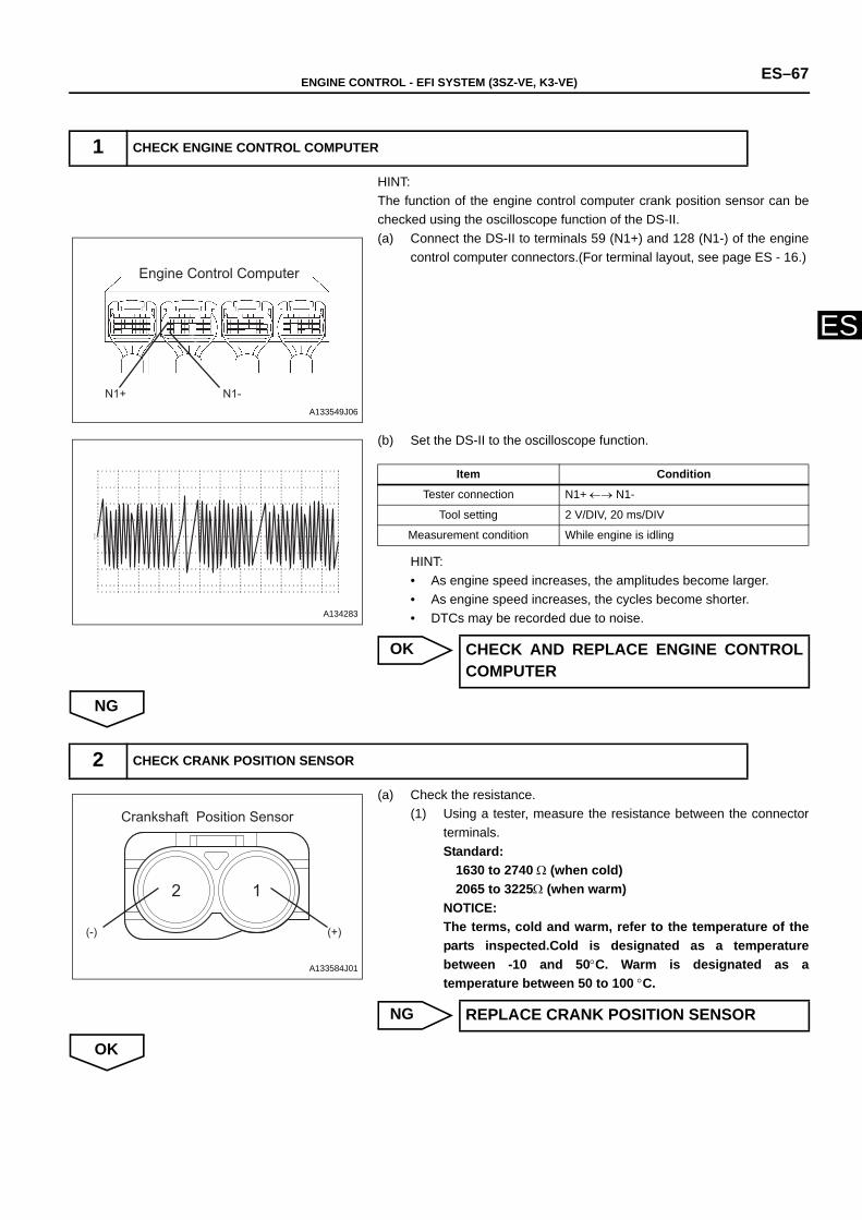
ENGINE CONTROL - EFI SYSTEM (3SZ-VE, K3-VE) ES–67
ES
HINT:The function of the engine control computer crank position sensor can bechecked using the oscilloscope function of the DS-II.(a) Connect the DS-II to terminals 59 (N1+) and 128 (N1-) of the engine
control computer connectors.(For terminal layout, see page ES - 16.)
(b) Set the DS-II to the oscilloscope function.
HINT:• As engine speed increases, the amplitudes become larger.• As engine speed increases, the cycles become shorter.• DTCs may be recorded due to noise.
OK
NG
(a) Check the resistance.(1) Using a tester, measure the resistance between the connector
terminals.Standard:
1630 to 2740 Ω (when cold)2065 to 3225Ω (when warm)
NOTICE:The terms, cold and warm, refer to the temperature of theparts inspected.Cold is designated as a temperaturebetween -10 and 50°C. Warm is designated as atemperature between 50 to 100 °C.
NG
OK
1 CHECK ENGINE CONTROL COMPUTER
Engine Control Computer
N1+ N1-A133549J06
A134283
Item Condition
Tester connection N1+ ←→ N1-
Tool setting 2 V/DIV, 20 ms/DIV
Measurement condition While engine is idling
CHECK AND REPLACE ENGINE CONTROLCOMPUTER
2 CHECK CRANK POSITION SENSOR
12
Crankshaft Position Sensor
(-) (+)
A133584J01
REPLACE CRANK POSITION SENSOR
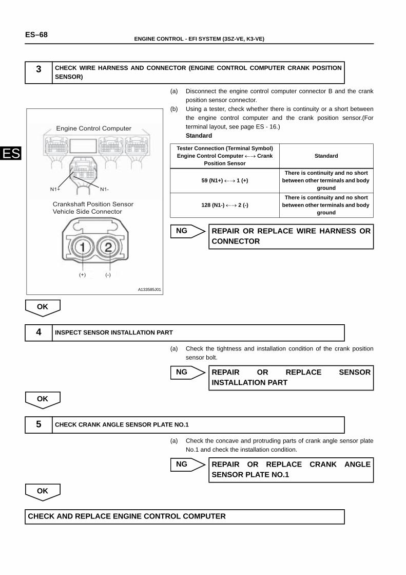
ES–68 ENGINE CONTROL - EFI SYSTEM (3SZ-VE, K3-VE)
ES
(a) Disconnect the engine control computer connector B and the crankposition sensor connector.
(b) Using a tester, check whether there is continuity or a short betweenthe engine control computer and the crank position sensor.(Forterminal layout, see page ES - 16.)Standard
NG
OK
(a) Check the tightness and installation condition of the crank positionsensor bolt.
NG
OK
(a) Check the concave and protruding parts of crank angle sensor plateNo.1 and check the installation condition.
NG
OK
3 CHECK WIRE HARNESS AND CONNECTOR (ENGINE CONTROL COMPUTER CRANK POSITIONSENSOR)
N1+ N1-
(+) (-)
Engine Control Computer
Crankshaft Position SensorVehicle Side Connector
A133585J01
Tester Connection (Terminal Symbol)Engine Control Computer ←→ Crank
Position Sensor Standard
59 (N1+) ←→ 1 (+)There is continuity and no short
between other terminals and body ground
128 (N1-) ←→ 2 (-)There is continuity and no short
between other terminals and body ground
REPAIR OR REPLACE WIRE HARNESS ORCONNECTOR
4 INSPECT SENSOR INSTALLATION PART
REPAIR OR REPLACE SENSORINSTALLATION PART
5 CHECK CRANK ANGLE SENSOR PLATE NO.1
REPAIR OR REPLACE CRANK ANGLESENSOR PLATE NO.1
CHECK AND REPLACE ENGINE CONTROL COMPUTER
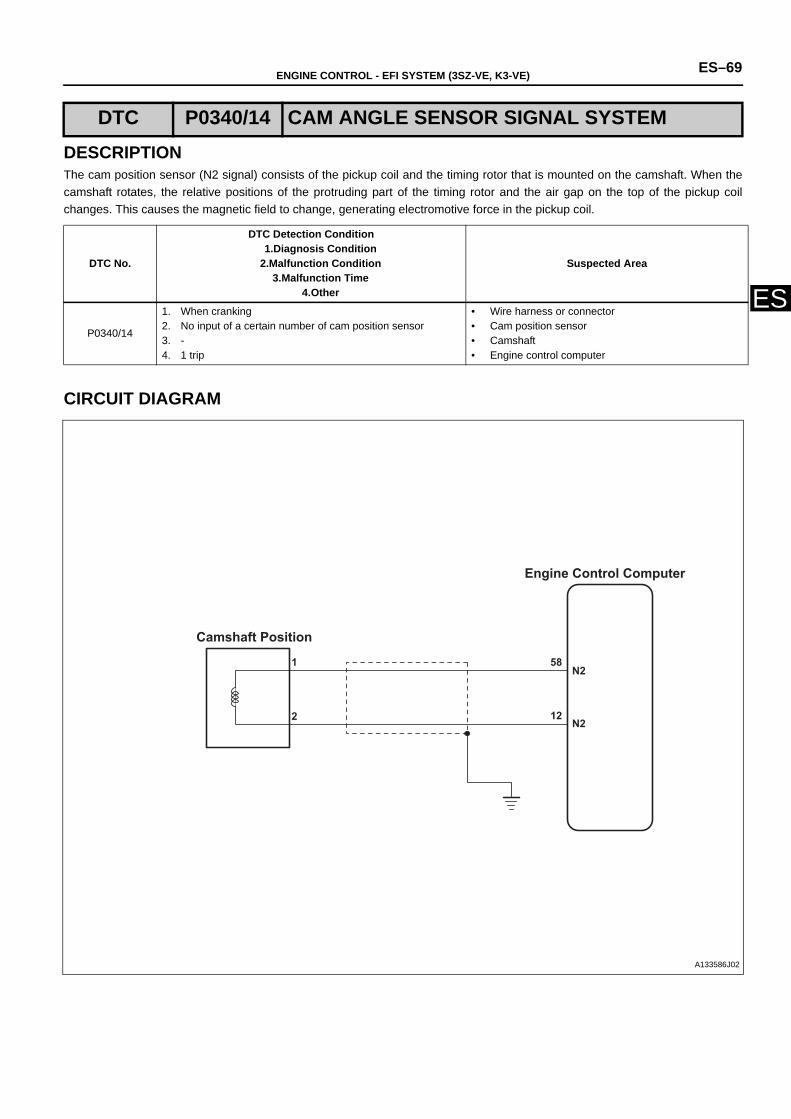
ENGINE CONTROL - EFI SYSTEM (3SZ-VE, K3-VE) ES–69
ES
DESCRIPTIONThe cam position sensor (N2 signal) consists of the pickup coil and the timing rotor that is mounted on the camshaft. When thecamshaft rotates, the relative positions of the protruding part of the timing rotor and the air gap on the top of the pickup coilchanges. This causes the magnetic field to change, generating electromotive force in the pickup coil.
CIRCUIT DIAGRAM
DTC P0340/14 CAM ANGLE SENSOR SIGNAL SYSTEM
DTC No.
DTC Detection Condition1.Diagnosis Condition
2.Malfunction Condition3.Malfunction Time
4.Other
Suspected Area
P0340/14
1. When cranking 2. No input of a certain number of cam position sensor 3. -4. 1 trip
• Wire harness or connector• Cam position sensor • Camshaft• Engine control computer
Camshaft Position
Engine Control Computer
1
2
58
12
N2
N2
A133586J02
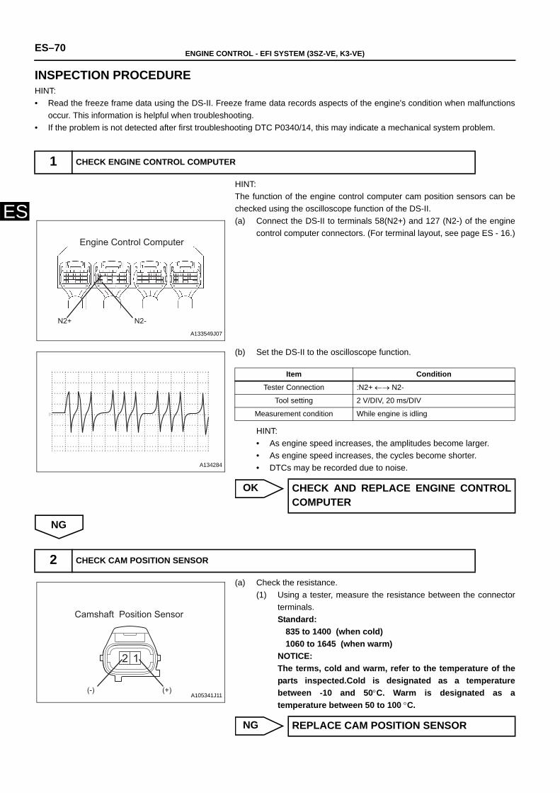
ES–70 ENGINE CONTROL - EFI SYSTEM (3SZ-VE, K3-VE)
ES
INSPECTION PROCEDUREHINT:• Read the freeze frame data using the DS-II. Freeze frame data records aspects of the engine's condition when malfunctions
occur. This information is helpful when troubleshooting.• If the problem is not detected after first troubleshooting DTC P0340/14, this may indicate a mechanical system problem.
HINT:The function of the engine control computer cam position sensors can bechecked using the oscilloscope function of the DS-II.(a) Connect the DS-II to terminals 58(N2+) and 127 (N2-) of the engine
control computer connectors. (For terminal layout, see page ES - 16.)
(b) Set the DS-II to the oscilloscope function.
HINT:• As engine speed increases, the amplitudes become larger.• As engine speed increases, the cycles become shorter.• DTCs may be recorded due to noise.
OK
NG
(a) Check the resistance.(1) Using a tester, measure the resistance between the connector
terminals.Standard:
835 to 1400 (when cold)1060 to 1645 (when warm)
NOTICE:The terms, cold and warm, refer to the temperature of theparts inspected.Cold is designated as a temperaturebetween -10 and 50°C. Warm is designated as atemperature between 50 to 100 °C.
NG
1 CHECK ENGINE CONTROL COMPUTER
Engine Control Computer
N2+ N2-A133549J07
A134284
Item Condition
Tester Connection :N2+ ←→ N2-
Tool setting 2 V/DIV, 20 ms/DIV
Measurement condition While engine is idling
CHECK AND REPLACE ENGINE CONTROLCOMPUTER
2 CHECK CAM POSITION SENSOR
12
(-) (+)
Camshaft Position Sensor
A105341J11
REPLACE CAM POSITION SENSOR
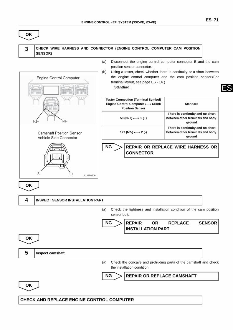
ENGINE CONTROL - EFI SYSTEM (3SZ-VE, K3-VE) ES–71
ES
OK
(a) Disconnect the engine control computer connector B and the camposition sensor connector.
(b) Using a tester, check whether there is continuity or a short betweenthe engine control computer and the cam position sensor.(Forterminal layout, see page ES - 16.)
Standard:
NG
OK
(a) Check the tightness and installation condition of the cam positionsensor bolt.
NG
OK
(a) Check the concave and protruding parts of the camshaft and checkthe installation condition.
NG
OK
3 CHECK WIRE HARNESS AND CONNECTOR (ENGINE CONTROL COMPUTER CAM POSITIONSENSOR)
Engine Control Computer
Camshaft Position Sensor Vehicle Side Connector
N2+ N2-
(+) (-)A133587J01
Tester Connection (Terminal Symbol)Engine Control Computer ←→ Crank
Position Sensor Standard
58 (N2+) ←→ 1 (+)There is continuity and no short
between other terminals and body ground
127 (N2-) ←→ 2 (-)There is continuity and no short
between other terminals and body ground
REPAIR OR REPLACE WIRE HARNESS ORCONNECTOR
4 INSPECT SENSOR INSTALLATION PART
REPAIR OR REPLACE SENSORINSTALLATION PART
5 Inspect camshaft
REPAIR OR REPLACE CAMSHAFT
CHECK AND REPLACE ENGINE CONTROL COMPUTER
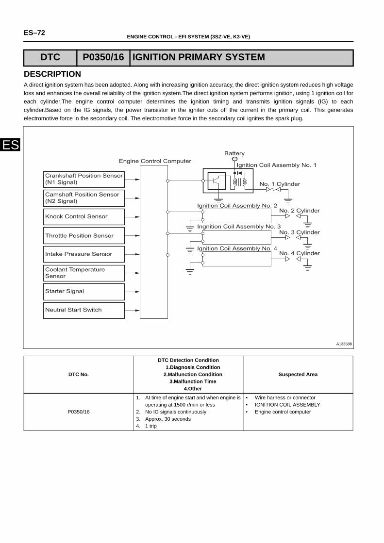
ES–72 ENGINE CONTROL - EFI SYSTEM (3SZ-VE, K3-VE)
ES
DESCRIPTIONA direct ignition system has been adopted. Along with increasing ignition accuracy, the direct ignition system reduces high voltageloss and enhances the overall reliability of the ignition system.The direct ignition system performs ignition, using 1 ignition coil foreach cylinder.The engine control computer determines the ignition timing and transmits ignition signals (IG) to eachcylinder.Based on the IG signals, the power transistor in the igniter cuts off the current in the primary coil. This generateselectromotive force in the secondary coil. The electromotive force in the secondary coil ignites the spark plug.
DTC P0350/16 IGNITION PRIMARY SYSTEM
DTC No.
DTC Detection Condition1.Diagnosis Condition
2.Malfunction Condition3.Malfunction Time
4.Other
Suspected Area
P0350/16
1. At time of engine start and when engine isoperating at 1500 r/min or less
2. No IG signals continuously3. Approx. 30 seconds 4. 1 trip
• Wire harness or connector• IGNITION COIL ASSEMBLY• Engine control computer
Engine Control ComputerBattery
Crankshaft Position Sensor (N1 Signal)
Camshaft Position Sensor (N2 Signal)
Knock Control Sensor
Throttle Position Sensor
Intake Pressure Sensor
Coolant Temperature Sensor
Starter Signal
Neutral Start Switch
Ignition Coil Assembly No. 1
No. 1 Cylinder
No. 2 Cylinder
No. 3 Cylinder
No. 4 Cylinder Ignition Coil Assembly No. 4
Ingnition Coil Assembly No. 3
Ignition Coil Assembly No. 2
A133588
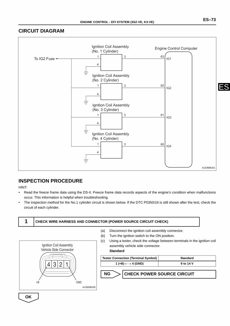
ENGINE CONTROL - EFI SYSTEM (3SZ-VE, K3-VE) ES–73
ES
CIRCUIT DIAGRAM
INSPECTION PROCEDUREHINT:• Read the freeze frame data using the DS-II. Freeze frame data records aspects of the engine's condition when malfunctions
occur. This information is helpful when troubleshooting.• The inspection method for the No.1 cylinder circuit is shown below. If the DTC P0350/16 is still shown after the test, check the
circuit of each cylinder.
(a) Disconnect the ignition coil assembly connector.(b) Turn the ignition switch to the ON position.(c) Using a tester, check the voltage between terminals in the ignition coil
assembly vehicle side connector.Standard
NG
OK
1 CHECK WIRE HARNESS AND CONNECTOR (POWER SOURCE CIRCUIT CHECK)
IG1
IG2
IG3
IG4
A9
A8
3
3
3
3
1
4
1
4
1
4
1
4
To IG2 Fuse
Ignition Coil Assembly (No. 1 Cylinder)
Ignition Coil Assembly (No. 2 Cylinder)
Ignition Coil Assembly (No. 3 Cylinder)
Ignition Coil Assembly (No. 4 Cylinder)
Engine Control Computer
63
62
61
60
A133589J01
Ignition Coil AssemblyVehicle Side Connector
+B GNDA109396J05
Tester Connection (Terminal Symbol) Standard
1 (+B) ←→ 4 (GND) 9 to 14 V
CHECK POWER SOURCE CIRCUIT
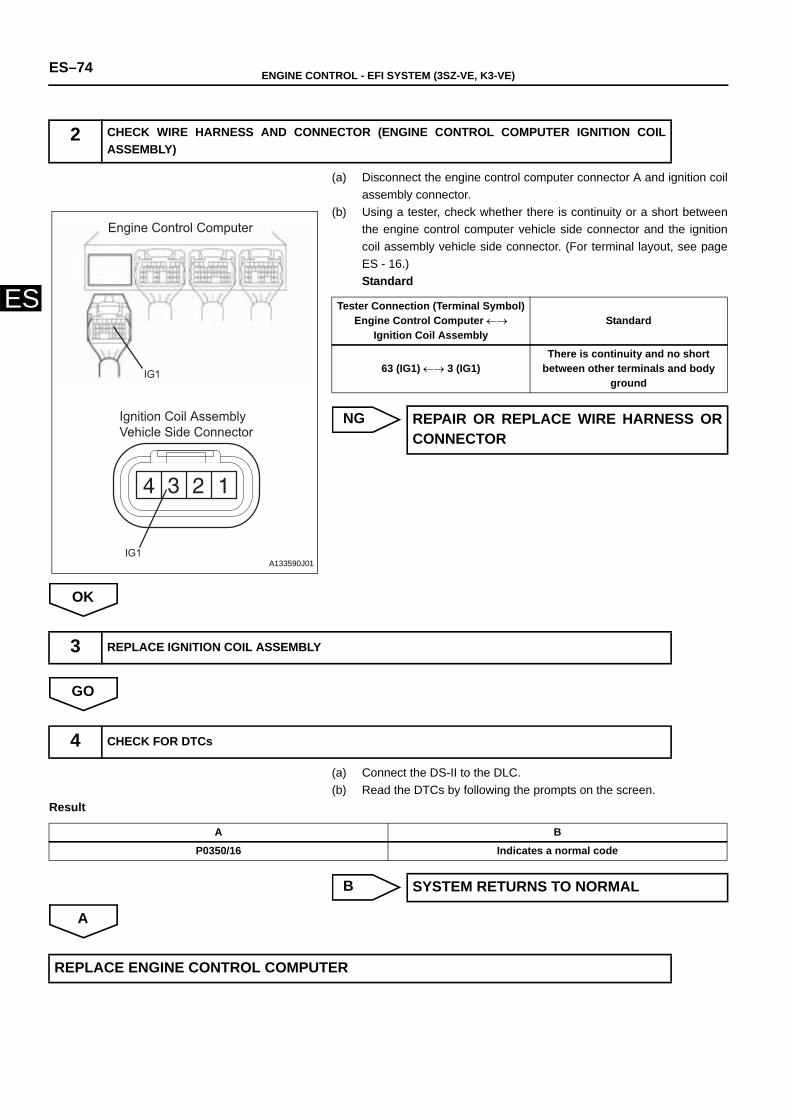
ES–74 ENGINE CONTROL - EFI SYSTEM (3SZ-VE, K3-VE)
ES
(a) Disconnect the engine control computer connector A and ignition coilassembly connector.
(b) Using a tester, check whether there is continuity or a short betweenthe engine control computer vehicle side connector and the ignitioncoil assembly vehicle side connector. (For terminal layout, see pageES - 16.)Standard
NG
OK
GO
(a) Connect the DS-II to the DLC.(b) Read the DTCs by following the prompts on the screen.
Result
B
A
2 CHECK WIRE HARNESS AND CONNECTOR (ENGINE CONTROL COMPUTER IGNITION COILASSEMBLY)
Engine Control Computer
Ignition Coil Assembly Vehicle Side Connector
IG1
IG1A133590J01
Tester Connection (Terminal Symbol)Engine Control Computer ←→
Ignition Coil Assembly Standard
63 (IG1) ←→ 3 (IG1)There is continuity and no short
between other terminals and body ground
REPAIR OR REPLACE WIRE HARNESS ORCONNECTOR
3 REPLACE IGNITION COIL ASSEMBLY
4 CHECK FOR DTCs
A B
P0350/16 Indicates a normal code
SYSTEM RETURNS TO NORMAL
REPLACE ENGINE CONTROL COMPUTER
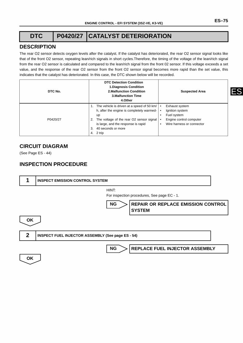
ENGINE CONTROL - EFI SYSTEM (3SZ-VE, K3-VE) ES–75
ES
DESCRIPTIONThe rear O2 sensor detects oxygen levels after the catalyst. If the catalyst has deteriorated, the rear O2 sensor signal looks likethat of the front O2 sensor, repeating lean/rich signals in short cycles.Therefore, the timing of the voltage of the lean/rich signalfrom the rear O2 sensor is calculated and compared to the lean/rich signal from the front 02 sensor. If this voltage exceeds a setvalue, and the response of the rear O2 sensor from the front O2 sensor signal becomes more rapid than the set value, thisindicates that the catalyst has deteriorated. In this case, the DTC shown below will be recorded.
CIRCUIT DIAGRAM(See Page ES - 44)
INSPECTION PROCEDURE
HINT:For inspection procedures, See page EC - 1.
NG
OK
NG
OK
DTC P0420/27 CATALYST DETERIORATION
DTC No.
DTC Detection Condition1.Diagnosis Condition
2.Malfunction Condition3.Malfunction Time
4.Other
Suspected Area
P0420/27
1. The vehicle is driven at a speed of 50 km/h, after the engine is completely warmed-up
2. The voltage of the rear O2 sensor signalis large, and the response is rapid
3. 40 seconds or more4. 2 trip
• Exhaust system • Ignition system • Fuel system• Engine control computer• Wire harness or connector
1 INSPECT EMISSION CONTROL SYSTEM
REPAIR OR REPLACE EMISSION CONTROLSYSTEM
2 INSPECT FUEL INJECTOR ASSEMBLY (See page ES - 54)
REPLACE FUEL INJECTOR ASSEMBLY
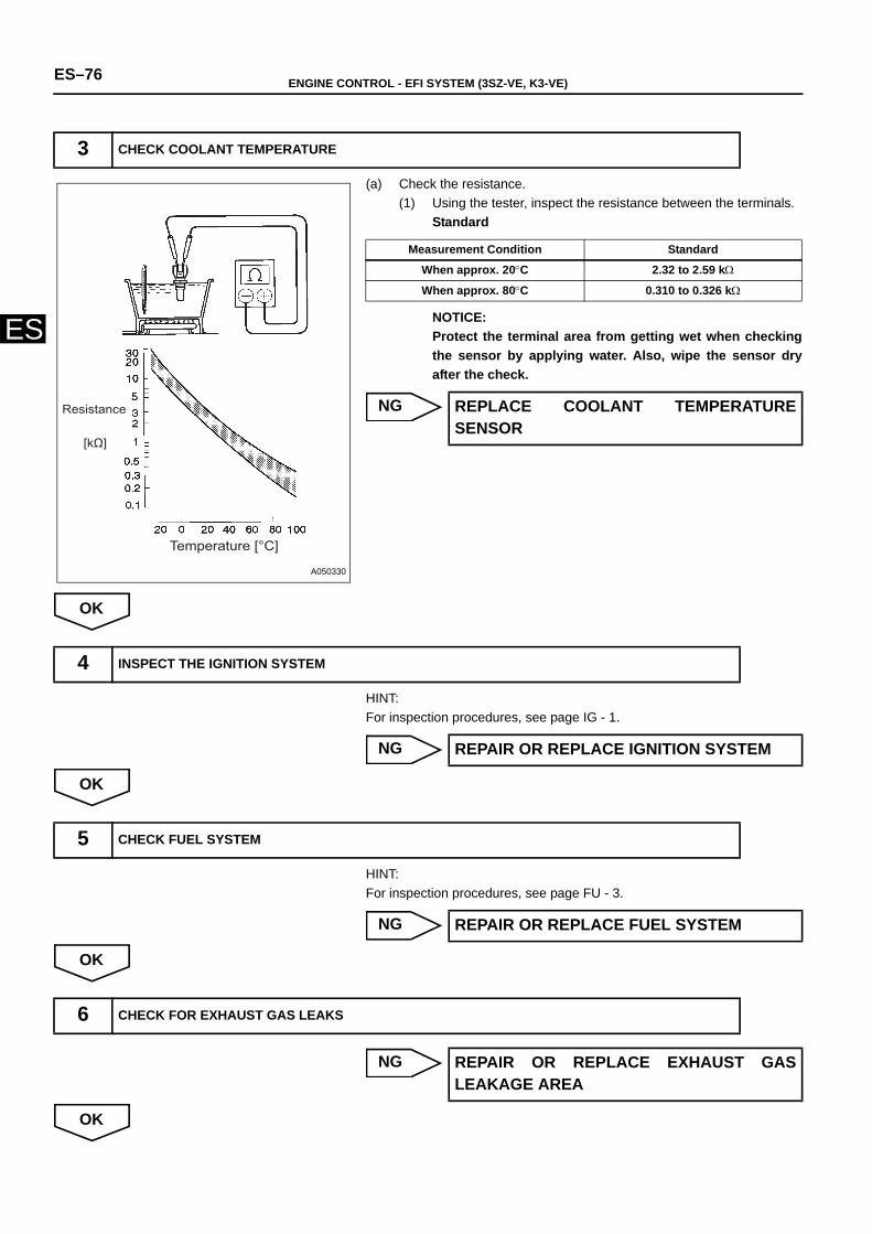
ES–76 ENGINE CONTROL - EFI SYSTEM (3SZ-VE, K3-VE)
ES
(a) Check the resistance.(1) Using the tester, inspect the resistance between the terminals.
Standard
NOTICE:Protect the terminal area from getting wet when checkingthe sensor by applying water. Also, wipe the sensor dryafter the check.
NG
OK
HINT:For inspection procedures, see page IG - 1.
NG
OK
HINT:For inspection procedures, see page FU - 3.
NG
OK
NG
OK
3 CHECK COOLANT TEMPERATURE
Temperature [°C]
Resistance
[kΩ]
A050330
Measurement Condition Standard
When approx. 20°C 2.32 to 2.59 kΩ
When approx. 80°C 0.310 to 0.326 kΩ
REPLACE COOLANT TEMPERATURESENSOR
4 INSPECT THE IGNITION SYSTEM
REPAIR OR REPLACE IGNITION SYSTEM
5 CHECK FUEL SYSTEM
REPAIR OR REPLACE FUEL SYSTEM
6 CHECK FOR EXHAUST GAS LEAKS
REPAIR OR REPLACE EXHAUST GASLEAKAGE AREA
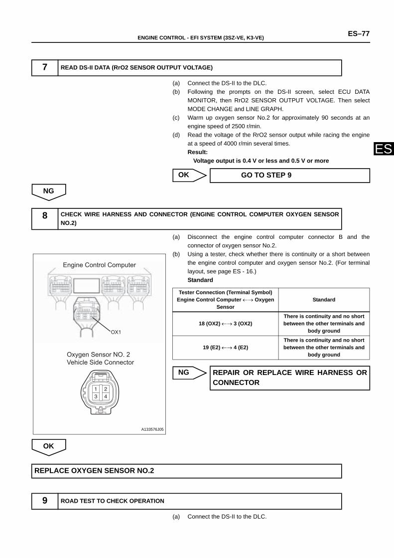
ENGINE CONTROL - EFI SYSTEM (3SZ-VE, K3-VE) ES–77
ES
(a) Connect the DS-II to the DLC.(b) Following the prompts on the DS-II screen, select ECU DATA
MONITOR, then RrO2 SENSOR OUTPUT VOLTAGE. Then selectMODE CHANGE and LINE GRAPH.
(c) Warm up oxygen sensor No.2 for approximately 90 seconds at anengine speed of 2500 r/min.
(d) Read the voltage of the RrO2 sensor output while racing the engineat a speed of 4000 r/min several times. Result:
Voltage output is 0.4 V or less and 0.5 V or more
OK
NG
(a) Disconnect the engine control computer connector B and theconnector of oxygen sensor No.2.
(b) Using a tester, check whether there is continuity or a short betweenthe engine control computer and oxygen sensor No.2. (For terminallayout, see page ES - 16.)Standard
NG
OK
(a) Connect the DS-II to the DLC.
7 READ DS-II DATA (RrO2 SENSOR OUTPUT VOLTAGE)
GO TO STEP 9
8 CHECK WIRE HARNESS AND CONNECTOR (ENGINE CONTROL COMPUTER OXYGEN SENSORNO.2)
Engine Control Computer
Oxygen Sensor NO. 2Vehicle Side Connector
OX1
A133576J05
Tester Connection (Terminal Symbol)Engine Control Computer ←→ Oxygen
Sensor Standard
18 (OX2) ←→ 3 (OX2)There is continuity and no short between the other terminals and
body ground
19 (E2) ←→ 4 (E2)There is continuity and no short between the other terminals and
body ground
REPAIR OR REPLACE WIRE HARNESS ORCONNECTOR
REPLACE OXYGEN SENSOR NO.2
9 ROAD TEST TO CHECK OPERATION
ES–78 ENGINE CONTROL - EFI SYSTEM (3SZ-VE, K3-VE)
ES
(b) Turn the ignition switch to the ON position, and delete the DTCs byfollowing the prompts on the DS-II screen.
(c) To check the system, warm up the oxygen sensor No.2 by performinga road test.HINT:Refer to the procedure for the oxygen sensor No.2 output voltageinspection.
GO
(a) Connect the DS-II to the DLC.(b) Turn the ignition switch to the ON position, and read the DTCs by
following the prompts on the DS-II screen.(1) Check if DTC P0420/27 is indicated.
Result
B
A
10 READ DTCs
A B
P0420/27 is output again P0420/27 is not output again
CHECK FOR INTERMITTENT PROBLEMS
CHECK AND REPLACE ENGINE CONTROL COMPUTER
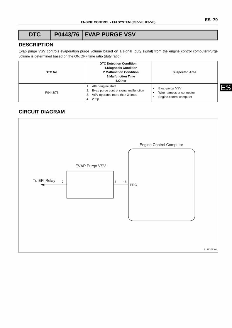
ENGINE CONTROL - EFI SYSTEM (3SZ-VE, K3-VE) ES–79
ES
DESCRIPTIONEvap purge VSV controls evaporation purge volume based on a signal (duty signal) from the engine control computer.Purgevolume is determined based on the ON/OFF time ratio (duty ratio).
CIRCUIT DIAGRAM
DTC P0443/76 EVAP PURGE VSV
DTC No.
DTC Detection Condition1.Diagnosis Condition
2.Malfunction Condition3.Malfunction Time
4.Other
Suspected Area
P0443/76
1. After engine start2. Evap purge control signal malfunction3. VSV operates more than 3 times4. 2 trip
• Evap purge VSV • Wire harness or connector• Engine control computer
Engine Control Computer
EVAP Purge VSV
To EFI Relay 2 1 16PRG
A138379J01
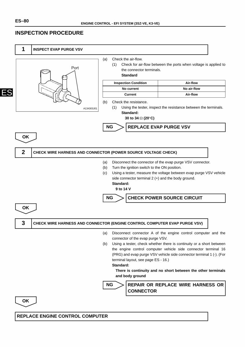
ES–80 ENGINE CONTROL - EFI SYSTEM (3SZ-VE, K3-VE)
ES
INSPECTION PROCEDURE
(a) Check the air-flow. (1) Check for air-flow between the ports when voltage is applied to
the connector terminals. Standard
(b) Check the resistance.(1) Using the tester, inspect the resistance between the terminals.
Standard:30 to 34 Ω (20°C)
NG
OK
(a) Disconnect the connector of the evap purge VSV connector.(b) Turn the ignition switch to the ON position.(c) Using a tester, measure the voltage between evap purge VSV vehicle
side connector terminal 2 (+) and the body ground.Standard:
9 to 14 V
NG
OK
(a) Disconnect connector A of the engine control computer and theconnector of the evap purge VSV.
(b) Using a tester, check whether there is continuity or a short betweenthe engine control computer vehicle side connector terminal 16(PRG) and evap purge VSV vehicle side connector terminal 1 (-). (Forterminal layout, see page ES - 16.)Standard:
There is continuity and no short between the other terminalsand body ground
NG
OK
1 INSPECT EVAP PURGE VSV
Port
A134303J01
Inspection Condition Air-flow
No current No air-flow
Current Air-flow
REPLACE EVAP PURGE VSV
2 CHECK WIRE HARNESS AND CONNECTOR (POWER SOURCE VOLTAGE CHECK)
CHECK POWER SOURCE CIRCUIT
3 CHECK WIRE HARNESS AND CONNECTOR (ENGINE CONTROL COMPUTER EVAP PURGE VSV)
REPAIR OR REPLACE WIRE HARNESS ORCONNECTOR
REPLACE ENGINE CONTROL COMPUTER
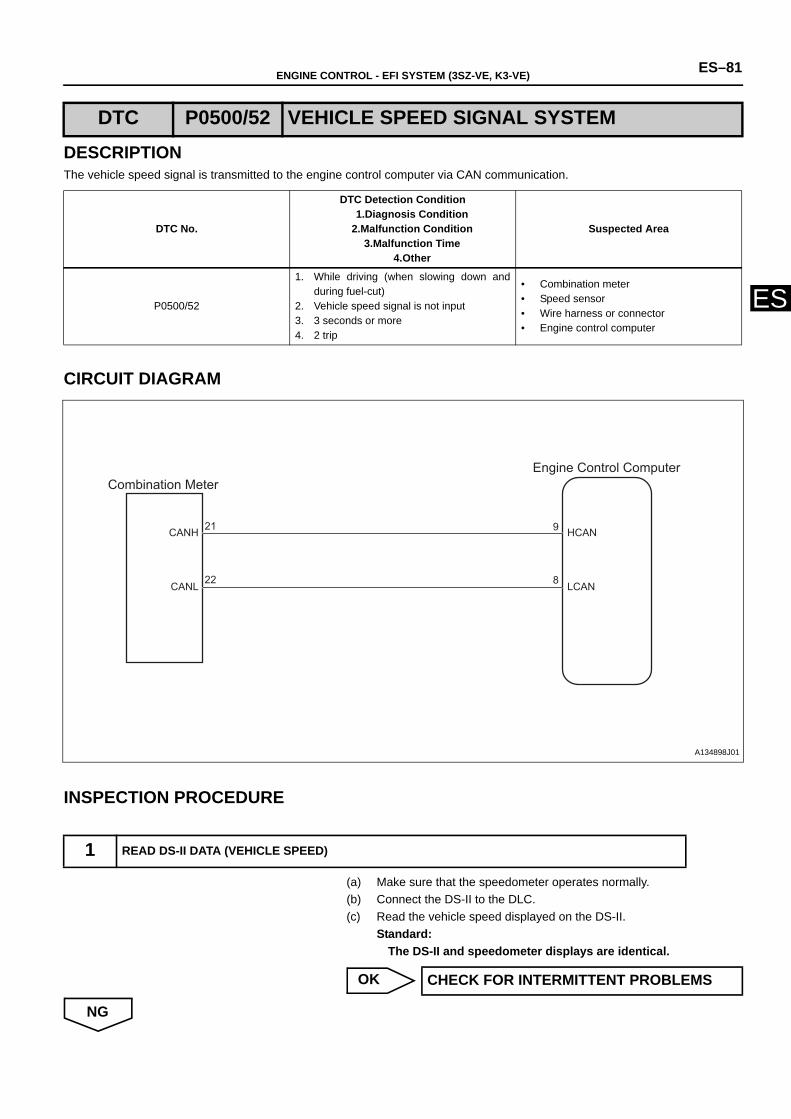
ENGINE CONTROL - EFI SYSTEM (3SZ-VE, K3-VE) ES–81
ES
DESCRIPTIONThe vehicle speed signal is transmitted to the engine control computer via CAN communication.
CIRCUIT DIAGRAM
INSPECTION PROCEDURE
(a) Make sure that the speedometer operates normally.(b) Connect the DS-II to the DLC.(c) Read the vehicle speed displayed on the DS-II.
Standard:The DS-II and speedometer displays are identical.
OK
NG
DTC P0500/52 VEHICLE SPEED SIGNAL SYSTEM
DTC No.
DTC Detection Condition1.Diagnosis Condition
2.Malfunction Condition3.Malfunction Time
4.Other
Suspected Area
P0500/52
1. While driving (when slowing down andduring fuel-cut)
2. Vehicle speed signal is not input3. 3 seconds or more4. 2 trip
• Combination meter • Speed sensor• Wire harness or connector• Engine control computer
1 READ DS-II DATA (VEHICLE SPEED)
21
22
HCAN
LCAN
CANH
CANL
Combination Meter Engine Control Computer
9
8
A134898J01
CHECK FOR INTERMITTENT PROBLEMS
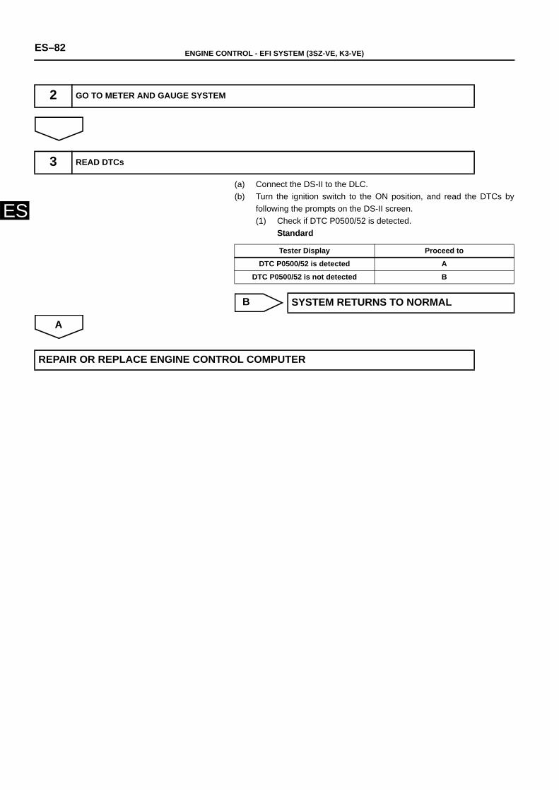
ES–82 ENGINE CONTROL - EFI SYSTEM (3SZ-VE, K3-VE)
ES(a) Connect the DS-II to the DLC.(b) Turn the ignition switch to the ON position, and read the DTCs by
following the prompts on the DS-II screen.(1) Check if DTC P0500/52 is detected.
Standard
B
A
2 GO TO METER AND GAUGE SYSTEM
3 READ DTCs
Tester Display Proceed to
DTC P0500/52 is detected A
DTC P0500/52 is not detected B
SYSTEM RETURNS TO NORMAL
REPAIR OR REPLACE ENGINE CONTROL COMPUTER
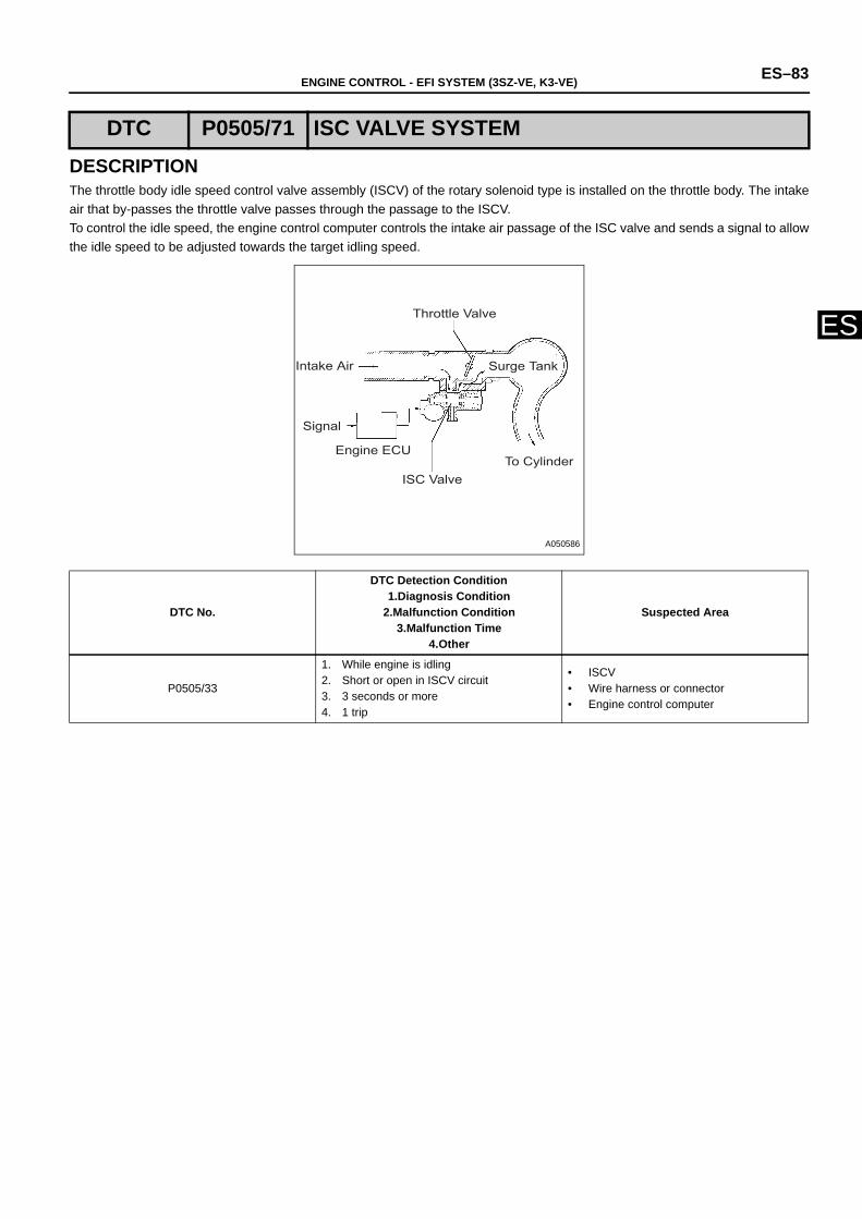
ENGINE CONTROL - EFI SYSTEM (3SZ-VE, K3-VE) ES–83
ES
DESCRIPTIONThe throttle body idle speed control valve assembly (ISCV) of the rotary solenoid type is installed on the throttle body. The intakeair that by-passes the throttle valve passes through the passage to the ISCV.To control the idle speed, the engine control computer controls the intake air passage of the ISC valve and sends a signal to allowthe idle speed to be adjusted towards the target idling speed.
DTC P0505/71 ISC VALVE SYSTEM
DTC No.
DTC Detection Condition1.Diagnosis Condition
2.Malfunction Condition3.Malfunction Time
4.Other
Suspected Area
P0505/33
1. While engine is idling2. Short or open in ISCV circuit3. 3 seconds or more4. 1 trip
• ISCV• Wire harness or connector• Engine control computer
Throttle Valve
Surge TankIntake Air
Signal
Engine ECU
ISC ValveTo Cylinder
A050586
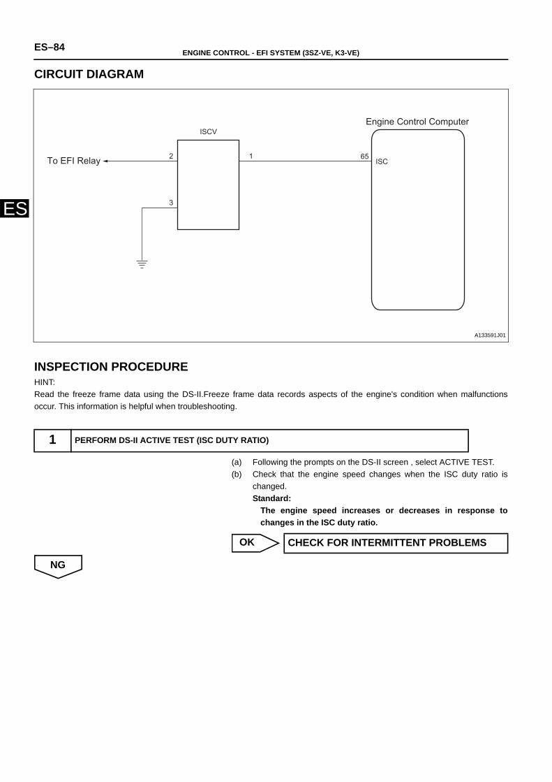
ES–84 ENGINE CONTROL - EFI SYSTEM (3SZ-VE, K3-VE)
ES
CIRCUIT DIAGRAM
INSPECTION PROCEDUREHINT:Read the freeze frame data using the DS-II.Freeze frame data records aspects of the engine's condition when malfunctionsoccur. This information is helpful when troubleshooting.
(a) Following the prompts on the DS-II screen , select ACTIVE TEST.(b) Check that the engine speed changes when the ISC duty ratio is
changed. Standard:
The engine speed increases or decreases in response tochanges in the ISC duty ratio.
OK
NG
1 PERFORM DS-II ACTIVE TEST (ISC DUTY RATIO)
ISCV
12
3
ISCTo EFI Relay
Engine Control Computer
65
A133591J01
CHECK FOR INTERMITTENT PROBLEMS
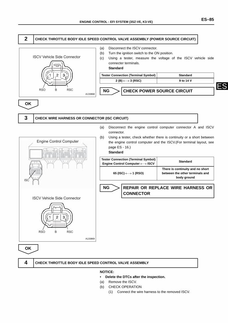
ENGINE CONTROL - EFI SYSTEM (3SZ-VE, K3-VE) ES–85
ES
(a) Disconnect the ISCV connector. (b) Turn the ignition switch to the ON position.(c) Using a tester, measure the voltage of the ISCV vehicle side
connecter terminals.Standard
NG
OK
(a) Disconnect the engine control computer connector A and ISCVconnector.
(b) Using a tester, check whether there is continuity or a short betweenthe engine control computer and the ISCV.(For terminal layout, seepage ES - 16.)Standard
NG
OK
NOTICE:• Delete the DTCs after the inspection. (a) Remove the ISCV.(b) CHECK OPERATION
(1) Connect the wire harness to the removed ISCV.
2 CHECK THROTTLE BODY IDLE SPEED CONTROL VALVE ASSEMBLY (POWER SOURCE CIRCUIT)
RSO B RSC
ISCV Vehicle Side Connector
A133868
Tester Connection (Terminal Symbol) Standard
2 (B) ←→ 3 (RSC) 9 to 14 V
CHECK POWER SOURCE CIRCUIT
3 CHECK WIRE HARNESS OR CONNECTOR (ISC CIRCUIT)
RSO B RSC
ISC
Engine Control Computer
ISCV Vehicle Side Connector
A133869
Tester Connection (Terminal Symbol)Engine Control Computer ←→ ISCV Standard
65 (ISC) ←→ 1 (RSO)There is continuity and no short between the other terminals and
body ground
REPAIR OR REPLACE WIRE HARNESS ORCONNECTOR
4 CHECK THROTTLE BODY IDLE SPEED CONTROL VALVE ASSEMBLY
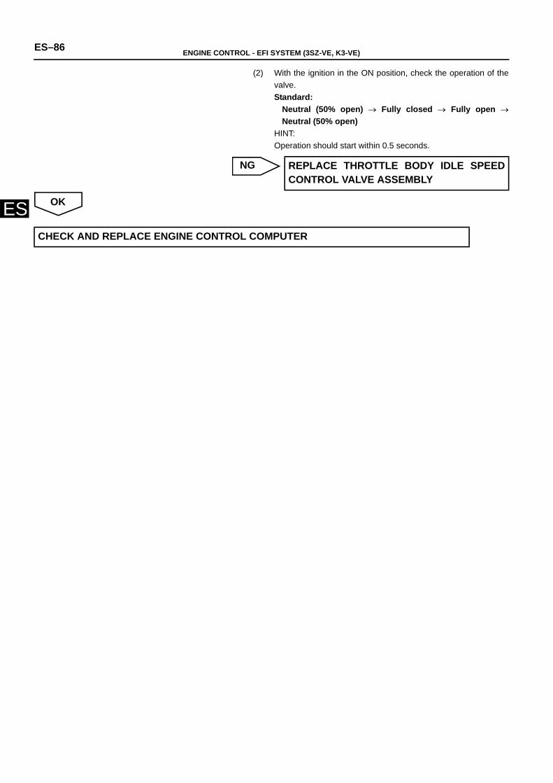
ES–86 ENGINE CONTROL - EFI SYSTEM (3SZ-VE, K3-VE)
ES
(2) With the ignition in the ON position, check the operation of thevalve. Standard:
Neutral (50% open) → Fully closed → Fully open →Neutral (50% open)
HINT:Operation should start within 0.5 seconds.
NG
OK
REPLACE THROTTLE BODY IDLE SPEEDCONTROL VALVE ASSEMBLY
CHECK AND REPLACE ENGINE CONTROL COMPUTER
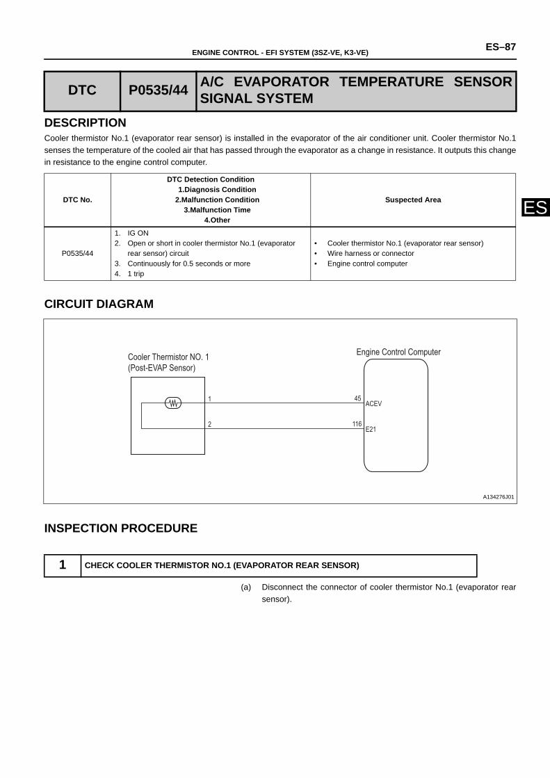
ENGINE CONTROL - EFI SYSTEM (3SZ-VE, K3-VE) ES–87
ES
DESCRIPTIONCooler thermistor No.1 (evaporator rear sensor) is installed in the evaporator of the air conditioner unit. Cooler thermistor No.1senses the temperature of the cooled air that has passed through the evaporator as a change in resistance. It outputs this changein resistance to the engine control computer.
CIRCUIT DIAGRAM
INSPECTION PROCEDURE
(a) Disconnect the connector of cooler thermistor No.1 (evaporator rearsensor).
DTC P0535/44 A/C EVAPORATOR TEMPERATURE SENSORSIGNAL SYSTEM
DTC No.
DTC Detection Condition1.Diagnosis Condition
2.Malfunction Condition3.Malfunction Time
4.Other
Suspected Area
P0535/44
1. IG ON2. Open or short in cooler thermistor No.1 (evaporator
rear sensor) circuit 3. Continuously for 0.5 seconds or more4. 1 trip
• Cooler thermistor No.1 (evaporator rear sensor) • Wire harness or connector• Engine control computer
1 CHECK COOLER THERMISTOR NO.1 (EVAPORATOR REAR SENSOR)
ACEV
E212
1
Engine Control Computer Cooler Thermistor NO. 1(Post-EVAP Sensor)
45
116
A134276J01
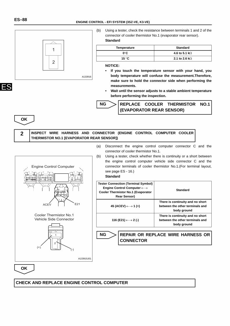
ES–88 ENGINE CONTROL - EFI SYSTEM (3SZ-VE, K3-VE)
ES
(b) Using a tester, check the resistance between terminals 1 and 2 of theconnector of cooler thermistor No.1 (evaporator rear sensor).Standard
NOTICE:• If you touch the temperature sensor with your hand, you
body temperature will confuse the measurement.Therefore,make sure to hold the connector side when performing themeasurements.
• Wait until the sensor adjusts to a stable ambient temperaturebefore performing the inspection.
NG
OK
(a) Disconnect the engine control computer connector C and theconnector of cooler thermistor No.1.
(b) Using a tester, check whether there is continuity or a short betweenthe engine control computer vehicle side connector C and theconnector terminals of cooler thermistor No.1.(For terminal layout,see page ES - 16.)Standard
NG
OK
1
2
A133916
Temperature Standard
0°C 4.6 to 5.1 kΩ
15 °C 2.1 to 2.6 kΩ
REPLACE COOLER THERMISTOR NO.1(EVAPORATOR REAR SENSOR)
2 INSPECT WIRE HARNESS AND CONNECTOR (ENGINE CONTROL COMPUTER COOLERTHERMISTOR NO.1 [EVAPORATOR REAR SENSOR])
Engine Control Computer
Cooler Thermistor No.1 Vehicle Side Connector
E21ACEV
(+)(-)
A133915J01
Tester Connection (Terminal Symbol)Engine Control Computer ←→
Cooler Thermistor No.1 (Evaporator Rear Sensor)
Standard
45 (ACEV) ←→ 1 (+)There is continuity and no short between the other terminals and
body ground
116 (E21) ←→ 2 (-)There is continuity and no short between the other terminals and
body ground
REPAIR OR REPLACE WIRE HARNESS ORCONNECTOR
CHECK AND REPLACE ENGINE CONTROL COMPUTER
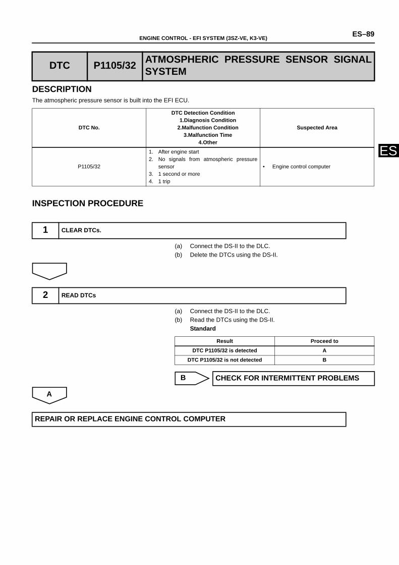
ENGINE CONTROL - EFI SYSTEM (3SZ-VE, K3-VE) ES–89
ES
DESCRIPTIONThe atmospheric pressure sensor is built into the EFI ECU.
INSPECTION PROCEDURE
(a) Connect the DS-II to the DLC.(b) Delete the DTCs using the DS-II.
(a) Connect the DS-II to the DLC.(b) Read the DTCs using the DS-II.
Standard
B
A
DTC P1105/32 ATMOSPHERIC PRESSURE SENSOR SIGNALSYSTEM
DTC No.
DTC Detection Condition1.Diagnosis Condition
2.Malfunction Condition3.Malfunction Time
4.Other
Suspected Area
P1105/32
1. After engine start2. No signals from atmospheric pressure
sensor 3. 1 second or more4. 1 trip
• Engine control computer
1 CLEAR DTCs.
2 READ DTCs
Result Proceed to
DTC P1105/32 is detected A
DTC P1105/32 is not detected B
CHECK FOR INTERMITTENT PROBLEMS
REPAIR OR REPLACE ENGINE CONTROL COMPUTER
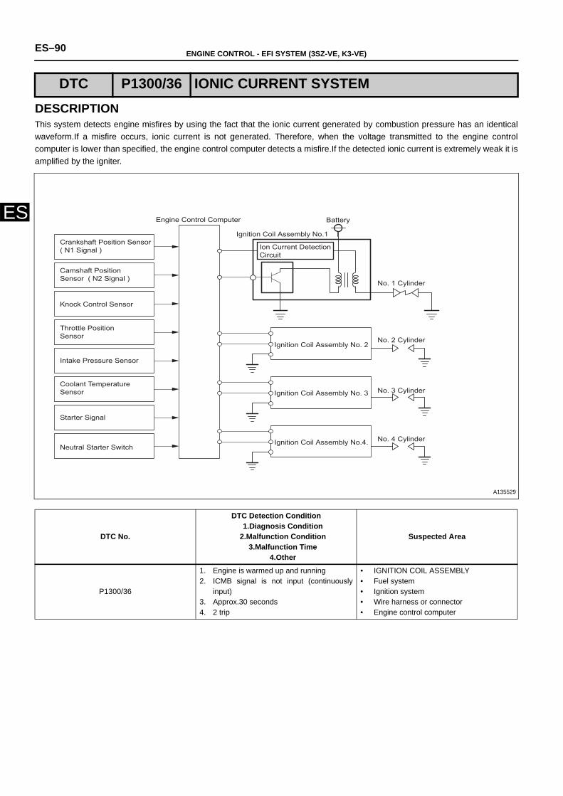
ES–90 ENGINE CONTROL - EFI SYSTEM (3SZ-VE, K3-VE)
ES
DESCRIPTIONThis system detects engine misfires by using the fact that the ionic current generated by combustion pressure has an identicalwaveform.If a misfire occurs, ionic current is not generated. Therefore, when the voltage transmitted to the engine controlcomputer is lower than specified, the engine control computer detects a misfire.If the detected ionic current is extremely weak it isamplified by the igniter.
DTC P1300/36 IONIC CURRENT SYSTEM
DTC No.
DTC Detection Condition1.Diagnosis Condition
2.Malfunction Condition3.Malfunction Time
4.Other
Suspected Area
P1300/36
1. Engine is warmed up and running 2. ICMB signal is not input (continuously
input)3. Approx.30 seconds 4. 2 trip
• IGNITION COIL ASSEMBLY• Fuel system• Ignition system • Wire harness or connector• Engine control computer
Crankshaft Position Sensor( N1 Signal )
Camshaft Position Sensor ( N2 Signal )
Knock Control Sensor
Throttle Position Sensor
Intake Pressure Sensor
Coolant TemperatureSensor
Starter Signal
Neutral Starter Switch
Engine Control Computer
Ignition Coil Assembly No.1
Battery
Ion Current Detection Circuit
No. 1 Cylinder
Ignition Coil Assembly No. 2No. 2 Cylinder
No. 3 Cylinder
No. 4 Cylinder
Ignition Coil Assembly No. 3
Ignition Coil Assembly No.4.
A135529
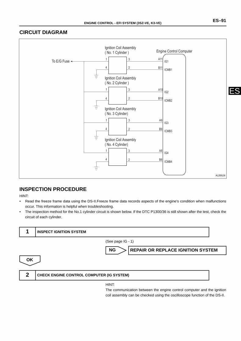
ENGINE CONTROL - EFI SYSTEM (3SZ-VE, K3-VE) ES–91
ES
CIRCUIT DIAGRAM
INSPECTION PROCEDUREHINT:• Read the freeze frame data using the DS-II.Freeze frame data records aspects of the engine's condition when malfunctions
occur. This information is helpful when troubleshooting.• The inspection method for the No.1 cylinder circuit is shown below. If the DTC P1300/36 is still shown after the test, check the
circuit of each cylinder.
(See page IG - 1)
NG
OK
HINT:The communication between the engine control computer and the ignitioncoil assembly can be checked using the oscilloscope function of the DS-II.
1 INSPECT IGNITION SYSTEM
IG1
ICMB1
ICMB2
ICMB3
ICMB4
IG2
IG3
IG4
A11
B11
B10
A10
A9
B9
A8
B8
3
2
2
2
2
3
3
3
1
4
1
4
1
4
1
4
Engine Control Computer Ignition Coil Assembly( No. 1 Cylinder )
To E/G Fuse
Ignition Coil Assembly ( No. 3 Cylinder)
Ignition Coil Assembly ( No. 4 Cylinder)
Ignition Coil Assembly ( No. 2 Cylinder )
A135526
REPAIR OR REPLACE IGNITION SYSTEM
2 CHECK ENGINE CONTROL COMPUTER (IG SYSTEM)
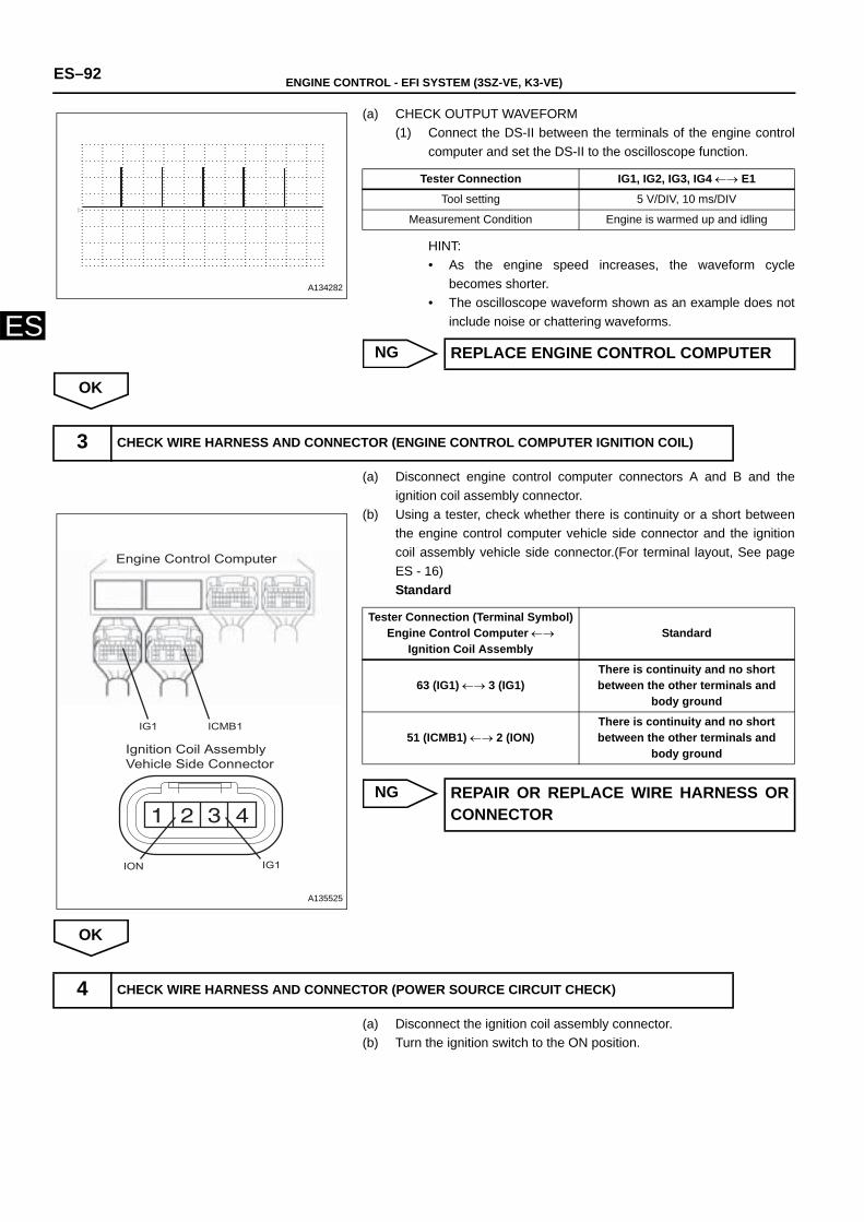
ES–92 ENGINE CONTROL - EFI SYSTEM (3SZ-VE, K3-VE)
ES
(a) CHECK OUTPUT WAVEFORM (1) Connect the DS-II between the terminals of the engine control
computer and set the DS-II to the oscilloscope function.
HINT:• As the engine speed increases, the waveform cycle
becomes shorter.• The oscilloscope waveform shown as an example does not
include noise or chattering waveforms.
NG
OK
(a) Disconnect engine control computer connectors A and B and theignition coil assembly connector.
(b) Using a tester, check whether there is continuity or a short betweenthe engine control computer vehicle side connector and the ignitioncoil assembly vehicle side connector.(For terminal layout, See pageES - 16)Standard
NG
OK
(a) Disconnect the ignition coil assembly connector.(b) Turn the ignition switch to the ON position.
A134282
Tester Connection IG1, IG2, IG3, IG4 ←→ E1
Tool setting 5 V/DIV, 10 ms/DIV
Measurement Condition Engine is warmed up and idling
REPLACE ENGINE CONTROL COMPUTER
3 CHECK WIRE HARNESS AND CONNECTOR (ENGINE CONTROL COMPUTER IGNITION COIL)
ION IG1
IG1 ICMB1
Engine Control Computer
Ignition Coil Assembly Vehicle Side Connector
A135525
Tester Connection (Terminal Symbol)Engine Control Computer ←→
Ignition Coil Assembly Standard
63 (IG1) ←→ 3 (IG1)There is continuity and no short between the other terminals and
body ground
51 (ICMB1) ←→ 2 (ION)There is continuity and no short between the other terminals and
body ground
REPAIR OR REPLACE WIRE HARNESS ORCONNECTOR
4 CHECK WIRE HARNESS AND CONNECTOR (POWER SOURCE CIRCUIT CHECK)
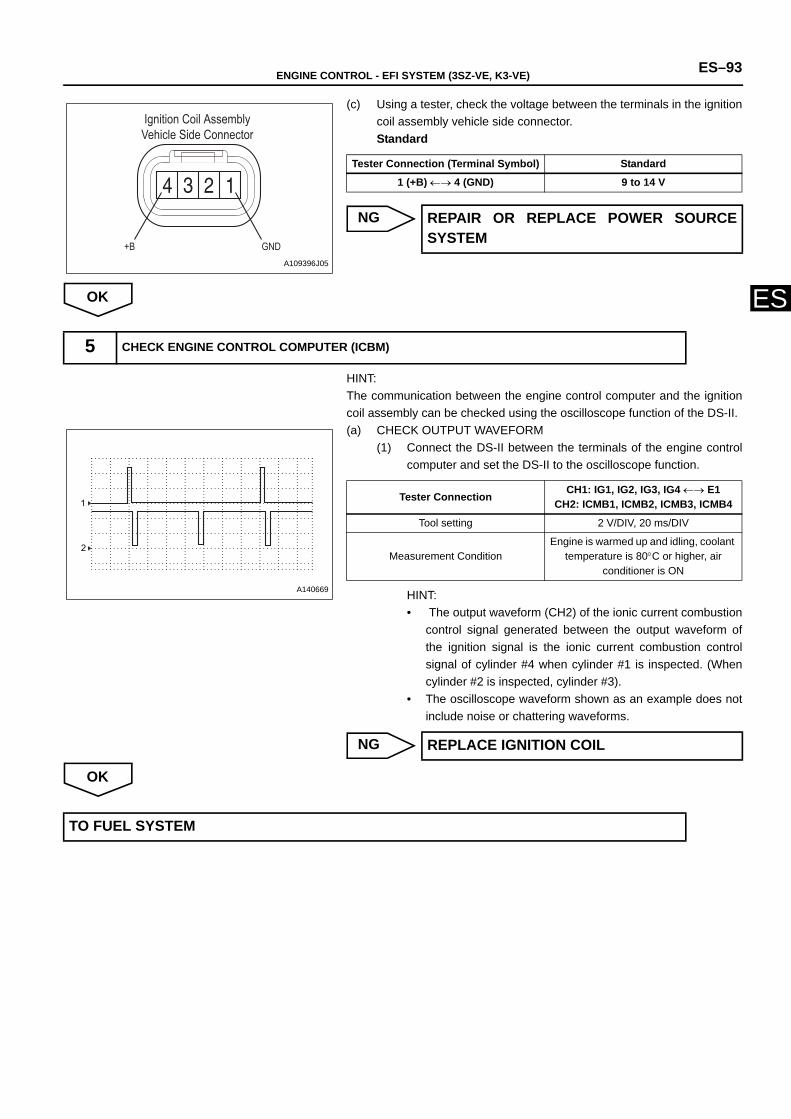
ENGINE CONTROL - EFI SYSTEM (3SZ-VE, K3-VE) ES–93
ES
(c) Using a tester, check the voltage between the terminals in the ignitioncoil assembly vehicle side connector.Standard
NG
OK
HINT:The communication between the engine control computer and the ignitioncoil assembly can be checked using the oscilloscope function of the DS-II.(a) CHECK OUTPUT WAVEFORM
(1) Connect the DS-II between the terminals of the engine controlcomputer and set the DS-II to the oscilloscope function.
HINT:• The output waveform (CH2) of the ionic current combustion
control signal generated between the output waveform ofthe ignition signal is the ionic current combustion controlsignal of cylinder #4 when cylinder #1 is inspected. (Whencylinder #2 is inspected, cylinder #3).
• The oscilloscope waveform shown as an example does notinclude noise or chattering waveforms.
NG
OK
Ignition Coil AssemblyVehicle Side Connector
+B GNDA109396J05
Tester Connection (Terminal Symbol) Standard
1 (+B) ←→ 4 (GND) 9 to 14 V
REPAIR OR REPLACE POWER SOURCESYSTEM
5 CHECK ENGINE CONTROL COMPUTER (ICBM)
1
2
A140669
Tester Connection CH1: IG1, IG2, IG3, IG4 ←→ E1CH2: ICMB1, ICMB2, ICMB3, ICMB4
Tool setting 2 V/DIV, 20 ms/DIV
Measurement ConditionEngine is warmed up and idling, coolant
temperature is 80°C or higher, air conditioner is ON
REPLACE IGNITION COIL
TO FUEL SYSTEM
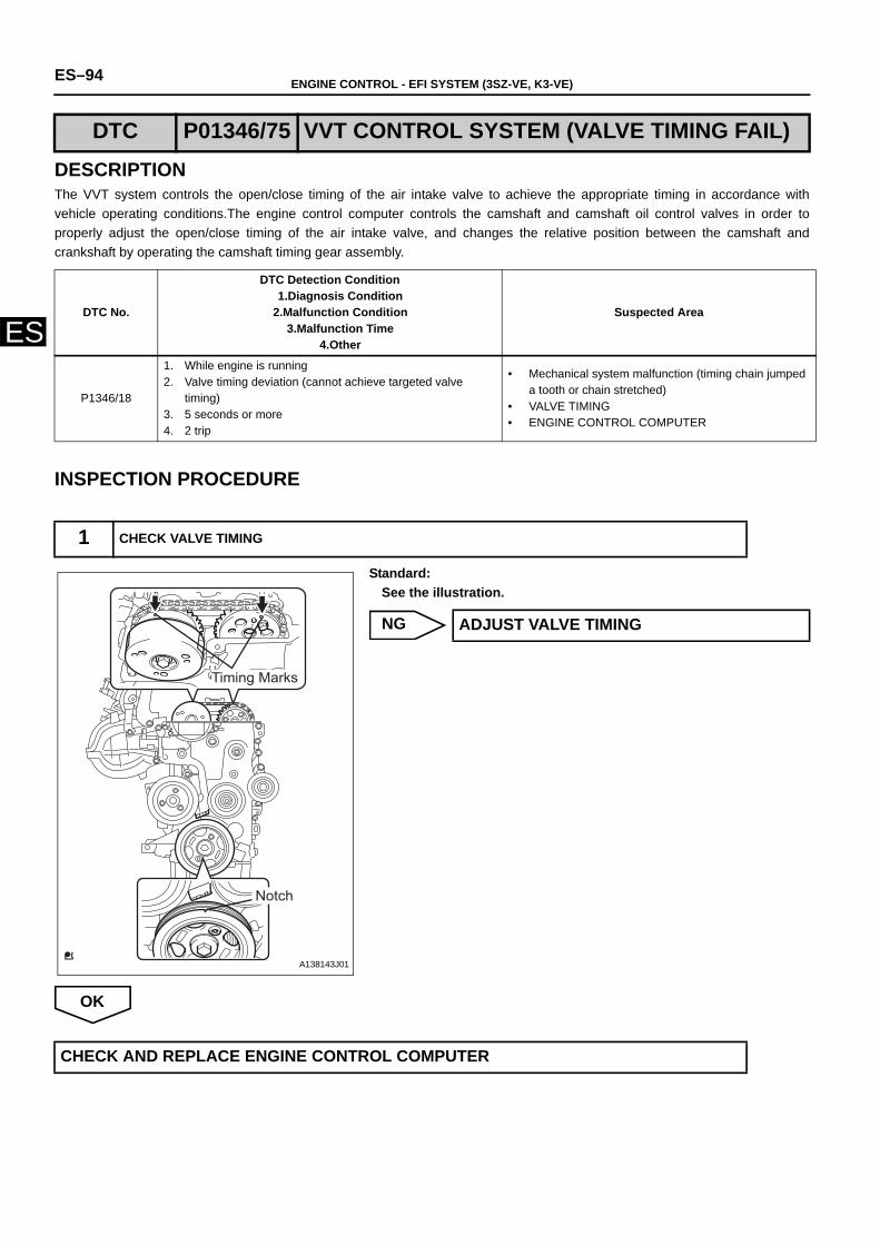
ES–94 ENGINE CONTROL - EFI SYSTEM (3SZ-VE, K3-VE)
ES
DESCRIPTIONThe VVT system controls the open/close timing of the air intake valve to achieve the appropriate timing in accordance withvehicle operating conditions.The engine control computer controls the camshaft and camshaft oil control valves in order toproperly adjust the open/close timing of the air intake valve, and changes the relative position between the camshaft andcrankshaft by operating the camshaft timing gear assembly.
INSPECTION PROCEDURE
Standard:See the illustration.
NG
OK
DTC P01346/75 VVT CONTROL SYSTEM (VALVE TIMING FAIL)
DTC No.
DTC Detection Condition1.Diagnosis Condition
2.Malfunction Condition3.Malfunction Time
4.Other
Suspected Area
P1346/18
1. While engine is running 2. Valve timing deviation (cannot achieve targeted valve
timing) 3. 5 seconds or more4. 2 trip
• Mechanical system malfunction (timing chain jumped a tooth or chain stretched)
• VALVE TIMING• ENGINE CONTROL COMPUTER
1 CHECK VALVE TIMING
Timing Marks
Notch
A138143J01
ADJUST VALVE TIMING
CHECK AND REPLACE ENGINE CONTROL COMPUTER
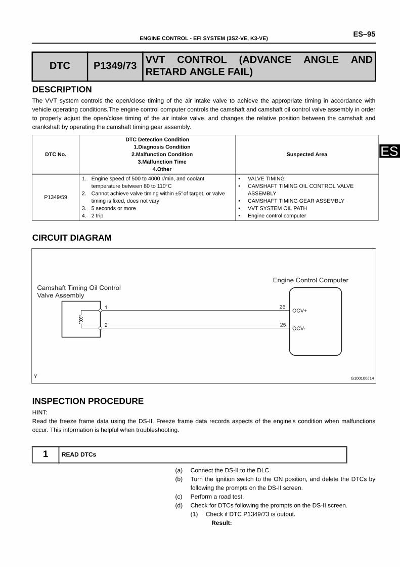
ENGINE CONTROL - EFI SYSTEM (3SZ-VE, K3-VE) ES–95
ES
DESCRIPTIONThe VVT system controls the open/close timing of the air intake valve to achieve the appropriate timing in accordance withvehicle operating conditions.The engine control computer controls the camshaft and camshaft oil control valve assembly in orderto properly adjust the open/close timing of the air intake valve, and changes the relative position between the camshaft andcrankshaft by operating the camshaft timing gear assembly.
CIRCUIT DIAGRAM
INSPECTION PROCEDUREHINT:Read the freeze frame data using the DS-II. Freeze frame data records aspects of the engine's condition when malfunctionsoccur. This information is helpful when troubleshooting.
(a) Connect the DS-II to the DLC.(b) Turn the ignition switch to the ON position, and delete the DTCs by
following the prompts on the DS-II screen.(c) Perform a road test. (d) Check for DTCs following the prompts on the DS-II screen.
(1) Check if DTC P1349/73 is output.Result:
DTC P1349/73 VVT CONTROL (ADVANCE ANGLE ANDRETARD ANGLE FAIL)
DTC No.
DTC Detection Condition1.Diagnosis Condition
2.Malfunction Condition3.Malfunction Time
4.Other
Suspected Area
P1349/59
1. Engine speed of 500 to 4000 r/min, and coolant temperature between 80 to 110°C
2. Cannot achieve valve timing within ±5°of target, or valve timing is fixed, does not vary
3. 5 seconds or more4. 2 trip
• VALVE TIMING• CAMSHAFT TIMING OIL CONTROL VALVE
ASSEMBLY• CAMSHAFT TIMING GEAR ASSEMBLY• VVT SYSTEM OIL PATH• Engine control computer
1 READ DTCs
Engine Control Computer Camshaft Timing Oil Control Valve Assembly
1
2
OCV+
OCV-
26
25
G100100J14
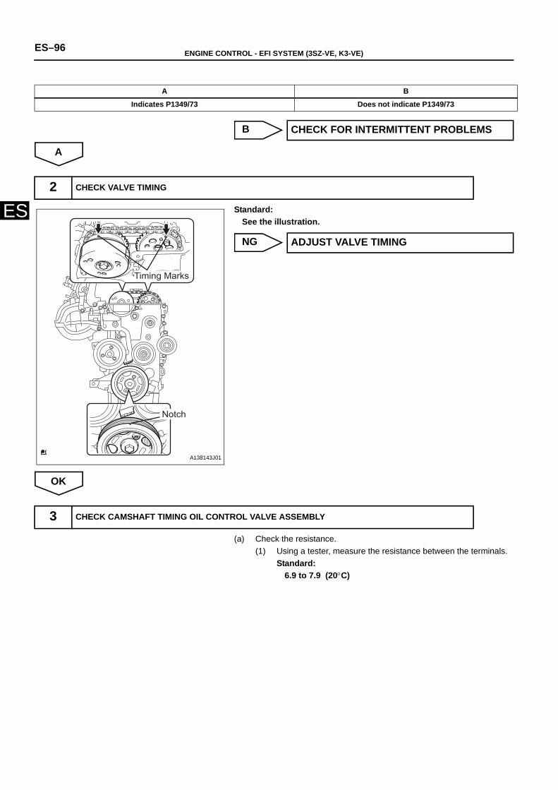
ES–96 ENGINE CONTROL - EFI SYSTEM (3SZ-VE, K3-VE)
ES
B
A
Standard:See the illustration.
NG
OK
(a) Check the resistance.(1) Using a tester, measure the resistance between the terminals.
Standard:6.9 to 7.9 (20°C)
A B
Indicates P1349/73 Does not indicate P1349/73
CHECK FOR INTERMITTENT PROBLEMS
2 CHECK VALVE TIMING
Timing Marks
Notch
A138143J01
ADJUST VALVE TIMING
3 CHECK CAMSHAFT TIMING OIL CONTROL VALVE ASSEMBLY
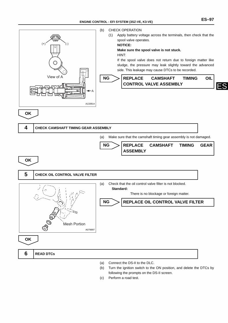
ENGINE CONTROL - EFI SYSTEM (3SZ-VE, K3-VE) ES–97
ES
(b) CHECK OPERATION(1) Apply battery voltage across the terminals, then check that the
spool valve operates.NOTICE:Make sure the spool valve is not stuck.HINT:If the spool valve does not return due to foreign matter likesludge, the pressure may leak slightly toward the advancedside. This leakage may cause DTCs to be recorded.
NG
OK
(a) Make sure that the camshaft timing gear assembly is not damaged.
NG
OK
(a) Check that the oil control valve filter is not blocked.Standard:
There is no blockage or foreign matter.
NG
OK
(a) Connect the DS-II to the DLC.(b) Turn the ignition switch to the ON position, and delete the DTCs by
following the prompts on the DS-II screen.(c) Perform a road test.
(+) (-)
A
View of A
A133914
REPLACE CAMSHAFT TIMING OILCONTROL VALVE ASSEMBLY
4 CHECK CAMSHAFT TIMING GEAR ASSEMBLY
REPLACE CAMSHAFT TIMING GEARASSEMBLY
5 CHECK OIL CONTROL VALVE FILTER
Mesh PortionA079997
REPLACE OIL CONTROL VALVE FILTER
6 READ DTCs
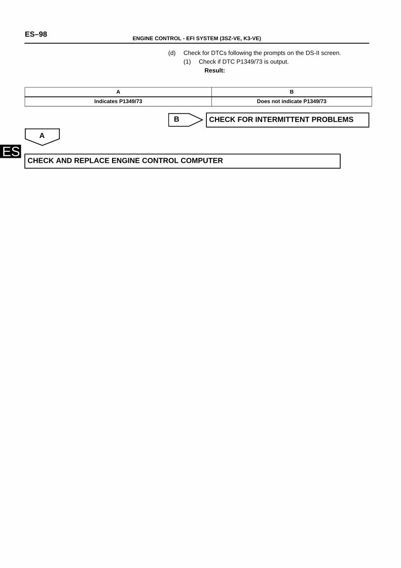
ES–98 ENGINE CONTROL - EFI SYSTEM (3SZ-VE, K3-VE)
ES
(d) Check for DTCs following the prompts on the DS-II screen.(1) Check if DTC P1349/73 is output.
Result:
B
A
A B
Indicates P1349/73 Does not indicate P1349/73
CHECK FOR INTERMITTENT PROBLEMS
CHECK AND REPLACE ENGINE CONTROL COMPUTER
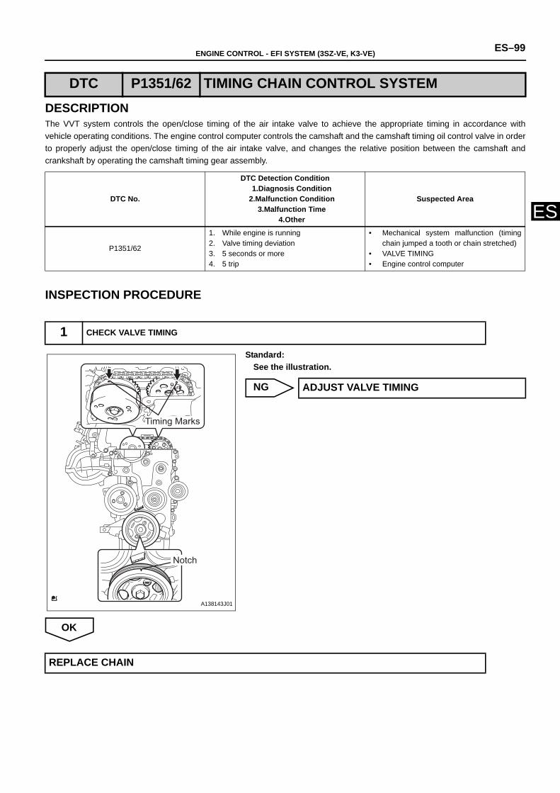
ENGINE CONTROL - EFI SYSTEM (3SZ-VE, K3-VE) ES–99
ES
DESCRIPTIONThe VVT system controls the open/close timing of the air intake valve to achieve the appropriate timing in accordance withvehicle operating conditions. The engine control computer controls the camshaft and the camshaft timing oil control valve in orderto properly adjust the open/close timing of the air intake valve, and changes the relative position between the camshaft andcrankshaft by operating the camshaft timing gear assembly.
INSPECTION PROCEDURE
Standard:See the illustration.
NG
OK
DTC P1351/62 TIMING CHAIN CONTROL SYSTEM
DTC No.
DTC Detection Condition1.Diagnosis Condition
2.Malfunction Condition3.Malfunction Time
4.Other
Suspected Area
P1351/62
1. While engine is running 2. Valve timing deviation3. 5 seconds or more4. 5 trip
• Mechanical system malfunction (timingchain jumped a tooth or chain stretched)
• VALVE TIMING• Engine control computer
1 CHECK VALVE TIMING
Timing Marks
Notch
A138143J01
ADJUST VALVE TIMING
REPLACE CHAIN
ES–100 ENGINE CONTROL - EFI SYSTEM (3SZ-VE, K3-VE)
ES
DESCRIPTIONThe starter operation signal is transmitted to the STSW terminal of the engine control computer while the engine cranks.Thestarter operating signal is used primarily for increasing fuel injection volume when the engine starts.
* : 2 trip for EU specifications.
DTC P1510/54 STARTER SIGNAL SYSTEM
DTC No.
DTC Detection Condition1.Diagnosis Condition
2.Malfunction Condition3.Malfunction Time
4.Other
Suspected Area
P1510/54
1. After engine start2. There are no ON signals even when
engine speed reaches a set value at a vehicle speed of 0 km/h
3. -4. 1 trip *
• Wire harness or connector• Engine control computer
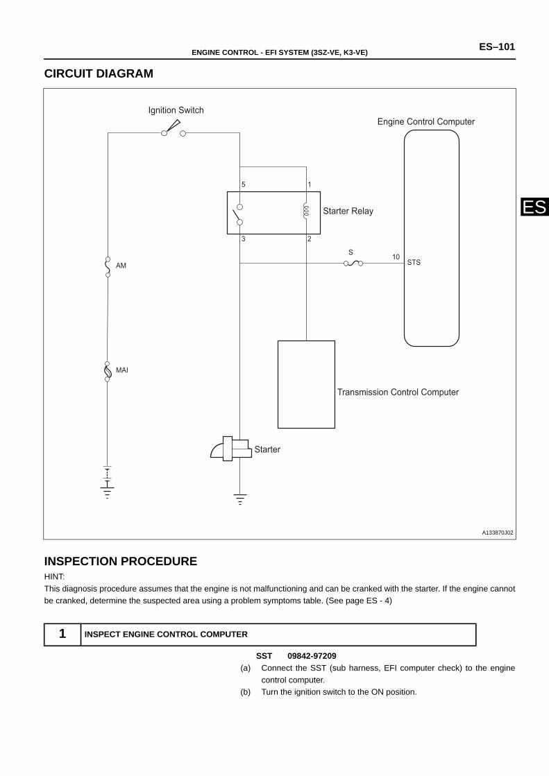
ENGINE CONTROL - EFI SYSTEM (3SZ-VE, K3-VE) ES–101
ES
CIRCUIT DIAGRAM
INSPECTION PROCEDUREHINT:This diagnosis procedure assumes that the engine is not malfunctioning and can be cranked with the starter. If the engine cannotbe cranked, determine the suspected area using a problem symptoms table. (See page ES - 4)
SST 09842-97209(a) Connect the SST (sub harness, EFI computer check) to the engine
control computer.(b) Turn the ignition switch to the ON position.
1 INSPECT ENGINE CONTROL COMPUTER
Ignition Switch
Starter Relay
Engine Control Computer
Transmission Control Computer
Starter
1
2
5
3
AM
MAI
S 10STS
A133870J02
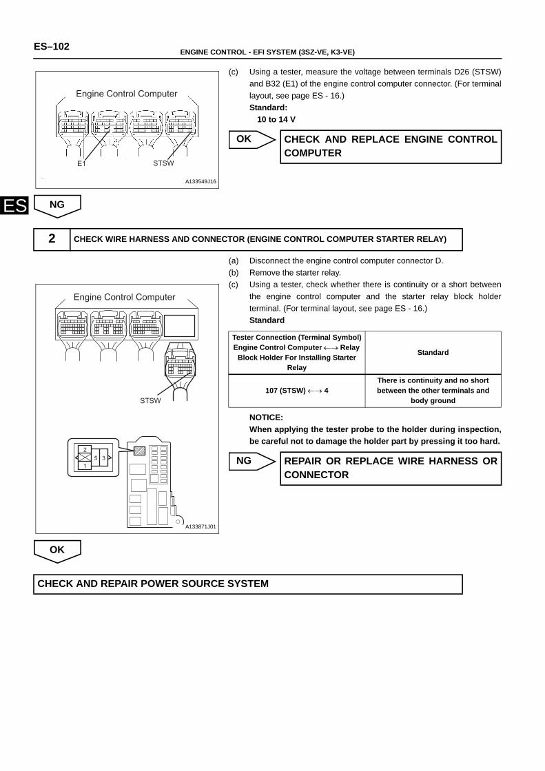
ES–102 ENGINE CONTROL - EFI SYSTEM (3SZ-VE, K3-VE)
ES
(c) Using a tester, measure the voltage between terminals D26 (STSW)and B32 (E1) of the engine control computer connector. (For terminallayout, see page ES - 16.)Standard:
10 to 14 V
OK
NG
(a) Disconnect the engine control computer connector D.(b) Remove the starter relay.(c) Using a tester, check whether there is continuity or a short between
the engine control computer and the starter relay block holderterminal. (For terminal layout, see page ES - 16.)Standard
NOTICE:When applying the tester probe to the holder during inspection,be careful not to damage the holder part by pressing it too hard.
NG
OK
Engine Control Computer
STSWE1
A133549J16
CHECK AND REPLACE ENGINE CONTROLCOMPUTER
2 CHECK WIRE HARNESS AND CONNECTOR (ENGINE CONTROL COMPUTER STARTER RELAY)
1
25 3
Engine Control Computer
STSW
A133871J01
Tester Connection (Terminal Symbol)Engine Control Computer ←→ Relay
Block Holder For Installing Starter Relay
Standard
107 (STSW) ←→ 4There is continuity and no short between the other terminals and
body ground
REPAIR OR REPLACE WIRE HARNESS ORCONNECTOR
CHECK AND REPAIR POWER SOURCE SYSTEM
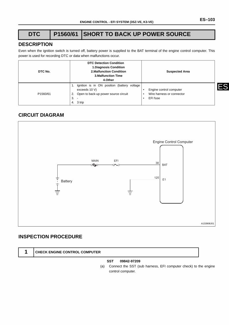
ENGINE CONTROL - EFI SYSTEM (3SZ-VE, K3-VE) ES–103
ES
DESCRIPTIONEven when the ignition switch is turned off, battery power is supplied to the BAT terminal of the engine control computer. Thispower is used for recording DTC or data when malfunctions occur.
CIRCUIT DIAGRAM
INSPECTION PROCEDURE
SST 09842-97209(a) Connect the SST (sub harness, EFI computer check) to the engine
control computer.
DTC P1560/61 SHORT TO BACK UP POWER SOURCE
DTC No.
DTC Detection Condition1.Diagnosis Condition
2.Malfunction Condition3.Malfunction Time
4.Other
Suspected Area
P1560/61
1. Ignition is in ON position (battery voltageexceeds 10 V)
2. Open to back-up power source circuit3. -4. 3 trip
• Engine control computer• Wire harness or connector• EFI fuse
1 CHECK ENGINE CONTROL COMPUTER
MAIN EFIBAT
E1
C7
B32Battery
Engine Control Computer
38
125
A133908J01
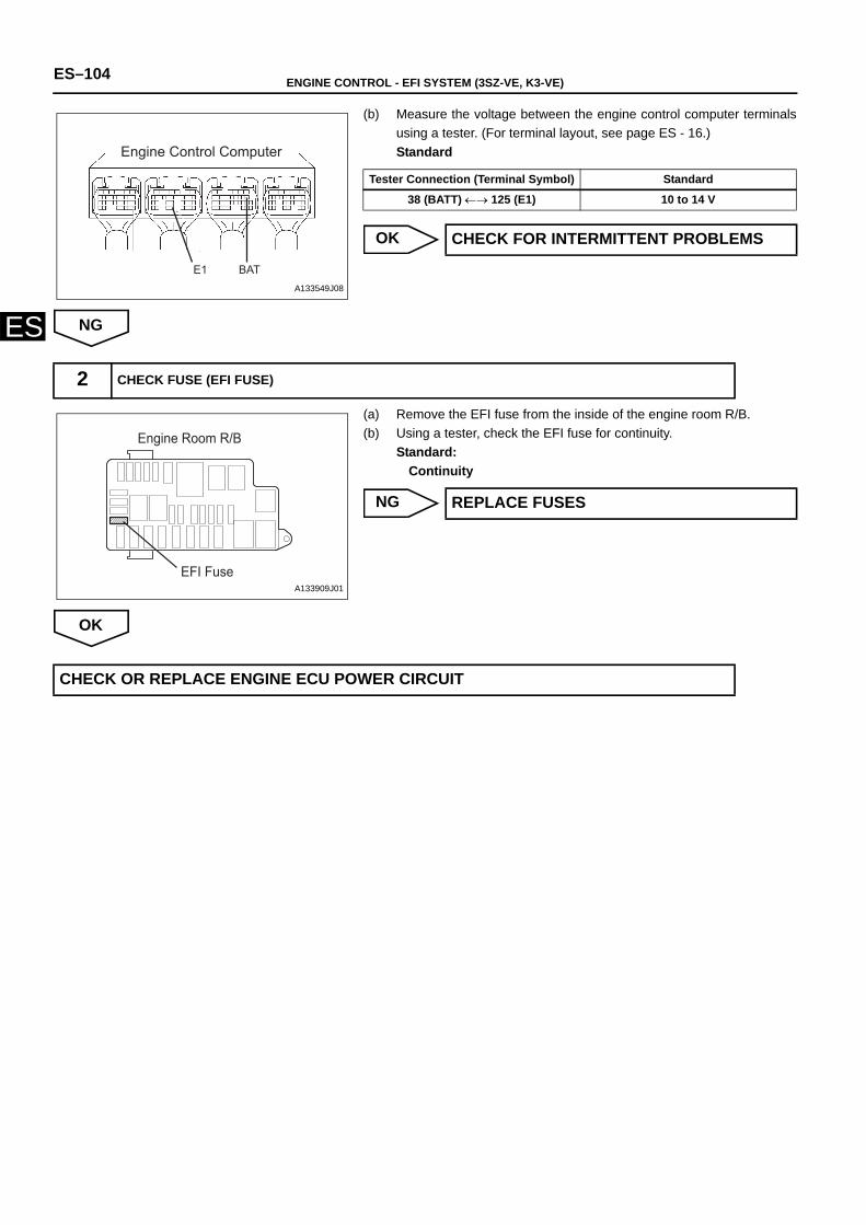
ES–104 ENGINE CONTROL - EFI SYSTEM (3SZ-VE, K3-VE)
ES
(b) Measure the voltage between the engine control computer terminalsusing a tester. (For terminal layout, see page ES - 16.)Standard
OK
NG
(a) Remove the EFI fuse from the inside of the engine room R/B. (b) Using a tester, check the EFI fuse for continuity.
Standard:Continuity
NG
OK
Engine Control Computer
E1 BATA133549J08
Tester Connection (Terminal Symbol) Standard
38 (BATT) ←→ 125 (E1) 10 to 14 V
CHECK FOR INTERMITTENT PROBLEMS
2 CHECK FUSE (EFI FUSE)
Engine Room R/B
EFI FuseA133909J01
REPLACE FUSES
CHECK OR REPLACE ENGINE ECU POWER CIRCUIT
ENGINE CONTROL - EFI SYSTEM (3SZ-VE, K3-VE) ES–105
ES
DESCRIPTIONThe transponder key computer assembly (immobiliser ECU) ensures security by controlling the START/END of thecommunication of matching codes with the engine control computer. It does so in accordance with ignition ON/OFF status and theimmobiliser SET/UNSET status. If the communication cannot be matched due to a malfunction in the engine control computer, aDTC is recorded.
INSPECTION PROCEDURE
(a) Connect the DS-II to the DLC.(b) Turn the ignition switch to the ON position, and read the DTCs by
following the prompts on the DS-II screen.HINT:If P1600/83 is detected, this indicates that the engine computer ismalfunctioning. Replace the engine control computer.
DTC P1600/83KEYLESS SYSTEM / IMMOBILISER SYSTEMCOMMUNICATION SYSTEM (MALFUNCTION INECU)
DTC No.
DTC Detection Condition1.Diagnosis Condition
2.Malfunction Condition3.Malfunction Time
4.Other
Suspected Area
P1600/83
1. IG ON2. Communication stopped with immobiliser
ECU3. 1 second or more4. 1 trip
• Engine control computer
1 READ DTCs
REPLACE ENGINE CONTROL COMPUTER
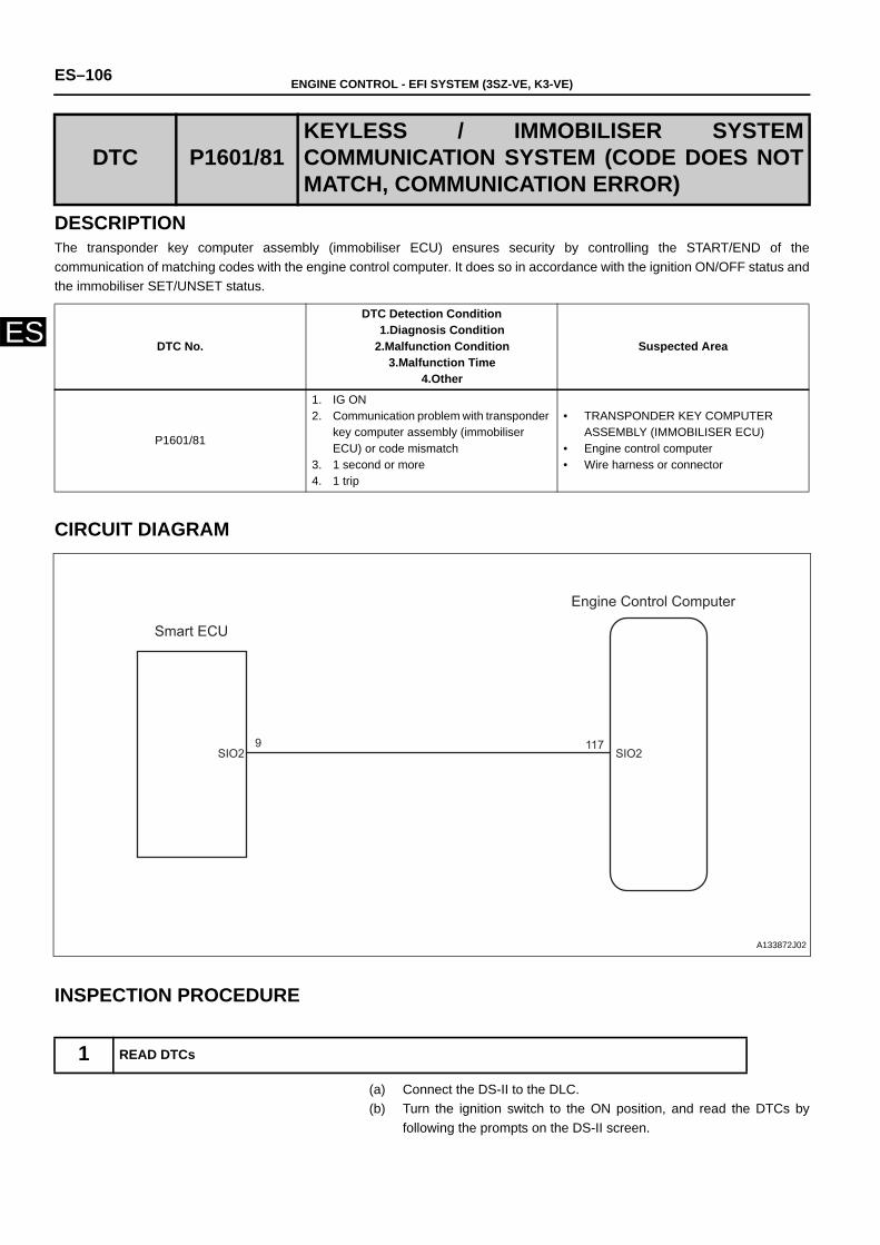
ES–106 ENGINE CONTROL - EFI SYSTEM (3SZ-VE, K3-VE)
ES
DESCRIPTIONThe transponder key computer assembly (immobiliser ECU) ensures security by controlling the START/END of thecommunication of matching codes with the engine control computer. It does so in accordance with the ignition ON/OFF status andthe immobiliser SET/UNSET status.
CIRCUIT DIAGRAM
INSPECTION PROCEDURE
(a) Connect the DS-II to the DLC.(b) Turn the ignition switch to the ON position, and read the DTCs by
following the prompts on the DS-II screen.
DTC P1601/81KEYLESS / IMMOBILISER SYSTEMCOMMUNICATION SYSTEM (CODE DOES NOTMATCH, COMMUNICATION ERROR)
DTC No.
DTC Detection Condition1.Diagnosis Condition
2.Malfunction Condition3.Malfunction Time
4.Other
Suspected Area
P1601/81
1. IG ON2. Communication problem with transponder
key computer assembly (immobiliser ECU) or code mismatch
3. 1 second or more4. 1 trip
• TRANSPONDER KEY COMPUTER ASSEMBLY (IMMOBILISER ECU)
• Engine control computer• Wire harness or connector
1 READ DTCs
SIO2 SIO29
Smart ECU
Engine Control Computer
117
A133872J02
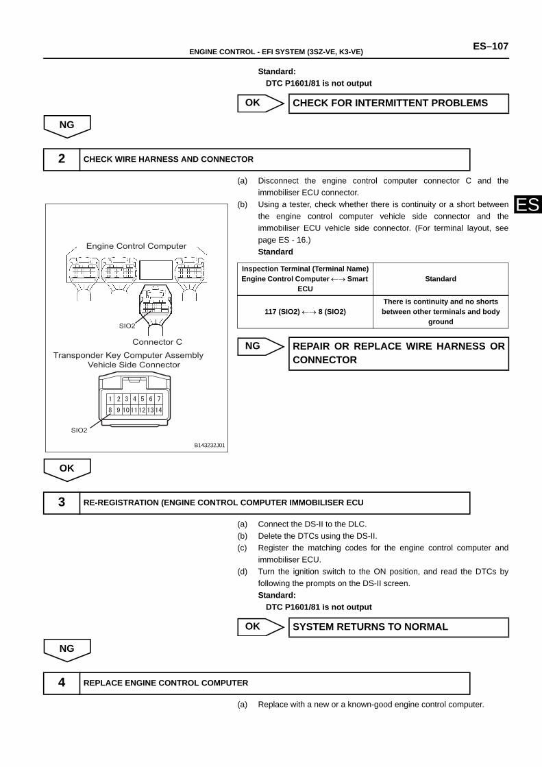
ENGINE CONTROL - EFI SYSTEM (3SZ-VE, K3-VE) ES–107
ES
Standard:DTC P1601/81 is not output
OK
NG
(a) Disconnect the engine control computer connector C and theimmobiliser ECU connector.
(b) Using a tester, check whether there is continuity or a short betweenthe engine control computer vehicle side connector and theimmobiliser ECU vehicle side connector. (For terminal layout, seepage ES - 16.)Standard
NG
OK
(a) Connect the DS-II to the DLC.(b) Delete the DTCs using the DS-II.(c) Register the matching codes for the engine control computer and
immobiliser ECU. (d) Turn the ignition switch to the ON position, and read the DTCs by
following the prompts on the DS-II screen.Standard:
DTC P1601/81 is not output
OK
NG
(a) Replace with a new or a known-good engine control computer.
CHECK FOR INTERMITTENT PROBLEMS
2 CHECK WIRE HARNESS AND CONNECTOR
Transponder Key Computer Assembly Vehicle Side Connector
Connector C
Engine Control Computer
SIO2
SIO2
B143232J01
Inspection Terminal (Terminal Name)Engine Control Computer ←→ Smart
ECUStandard
117 (SIO2) ←→ 8 (SIO2)There is continuity and no shorts between other terminals and body
ground
REPAIR OR REPLACE WIRE HARNESS ORCONNECTOR
3 RE-REGISTRATION (ENGINE CONTROL COMPUTER IMMOBILISER ECU
SYSTEM RETURNS TO NORMAL
4 REPLACE ENGINE CONTROL COMPUTER
ES–108 ENGINE CONTROL - EFI SYSTEM (3SZ-VE, K3-VE)
ES
(b) After replacing the engine control computer, register the keys, turnthe ignition switch to the ON position, then read the DTCs.Standard:
DTC P1601/81 is not output
OK
NG
SYSTEM RETURNS TO NORMAL
REPLACE TRANSPONDER KEY COMPUTER ASSEMBLY
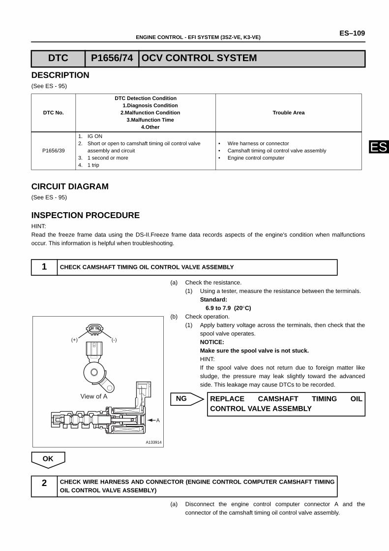
ENGINE CONTROL - EFI SYSTEM (3SZ-VE, K3-VE) ES–109
ES
DESCRIPTION(See ES - 95)
CIRCUIT DIAGRAM(See ES - 95)
INSPECTION PROCEDUREHINT:Read the freeze frame data using the DS-II.Freeze frame data records aspects of the engine's condition when malfunctionsoccur. This information is helpful when troubleshooting.
(a) Check the resistance.(1) Using a tester, measure the resistance between the terminals.
Standard:6.9 to 7.9 (20°C)
(b) Check operation.(1) Apply battery voltage across the terminals, then check that the
spool valve operates.NOTICE:Make sure the spool valve is not stuck.HINT:If the spool valve does not return due to foreign matter likesludge, the pressure may leak slightly toward the advancedside. This leakage may cause DTCs to be recorded.
NG
OK
(a) Disconnect the engine control computer connector A and theconnector of the camshaft timing oil control valve assembly.
DTC P1656/74 OCV CONTROL SYSTEM
DTC No.
DTC Detection Condition1.Diagnosis Condition
2.Malfunction Condition3.Malfunction Time
4.Other
Trouble Area
P1656/39
1. IG ON2. Short or open to camshaft timing oil control valve
assembly and circuit 3. 1 second or more4. 1 trip
• Wire harness or connector• Camshaft timing oil control valve assembly• Engine control computer
1 CHECK CAMSHAFT TIMING OIL CONTROL VALVE ASSEMBLY
(+) (-)
A
View of A
A133914
REPLACE CAMSHAFT TIMING OILCONTROL VALVE ASSEMBLY
2 CHECK WIRE HARNESS AND CONNECTOR (ENGINE CONTROL COMPUTER CAMSHAFT TIMINGOIL CONTROL VALVE ASSEMBLY)
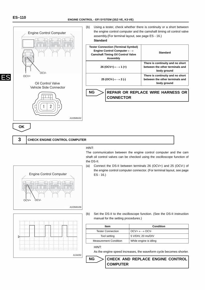
ES–110 ENGINE CONTROL - EFI SYSTEM (3SZ-VE, K3-VE)
ES
(b) Using a tester, check whether there is continuity or a short betweenthe engine control computer and the camshaft timing oil control valveassembly.(For terminal layout, see page ES - 16.)Standard
NG
OK
HINT:The communication between the engine control computer and the camshaft oil control valves can be checked using the oscilloscope function ofthe DS-II.(a) Connect the DS-II between terminals 26 (OCV+) and 25 (OCV-) of
the engine control computer connector. (For terminal layout, see pageES - 16.)
(b) Set the DS-II to the oscilloscope function. (See the DS-II instructionmanual for the setting procedures.)
HINT:As the engine speed increases, the waveform cycle becomes shorter.
NG
Engine Control Computer
Oil Control ValveVehicle Side Connector
OCV+OCV-
A103589J02
Tester Connection (Terminal Symbol)Engine Control Computer ←→
Camshaft Timing Oil Control Valve Assembly
Standard
26 (OCV+) ←→ 1 (+)There is continuity and no short between the other terminals and
body ground
25 (OCV-) ←→ 2 (-)There is continuity and no short between the other terminals and
body ground
REPAIR OR REPLACE WIRE HARNESS ORCONNECTOR
3 CHECK ENGINE CONTROL COMPUTER
Engine Control Computer
OCV+ OCV-
A103583J06
A134292
Item Condition
Tester Connection OCV+ ←→ OCV-
Tool setting 5 V/DIV, 20 ms/DIV
Measurement Condition While engine is idling
CHECK AND REPLACE ENGINE CONTROLCOMPUTER

ENGINE CONTROL - EFI SYSTEM (3SZ-VE, K3-VE) ES–111
ES
OK
CHECK FOR INTERMITTENT PROBLEMS
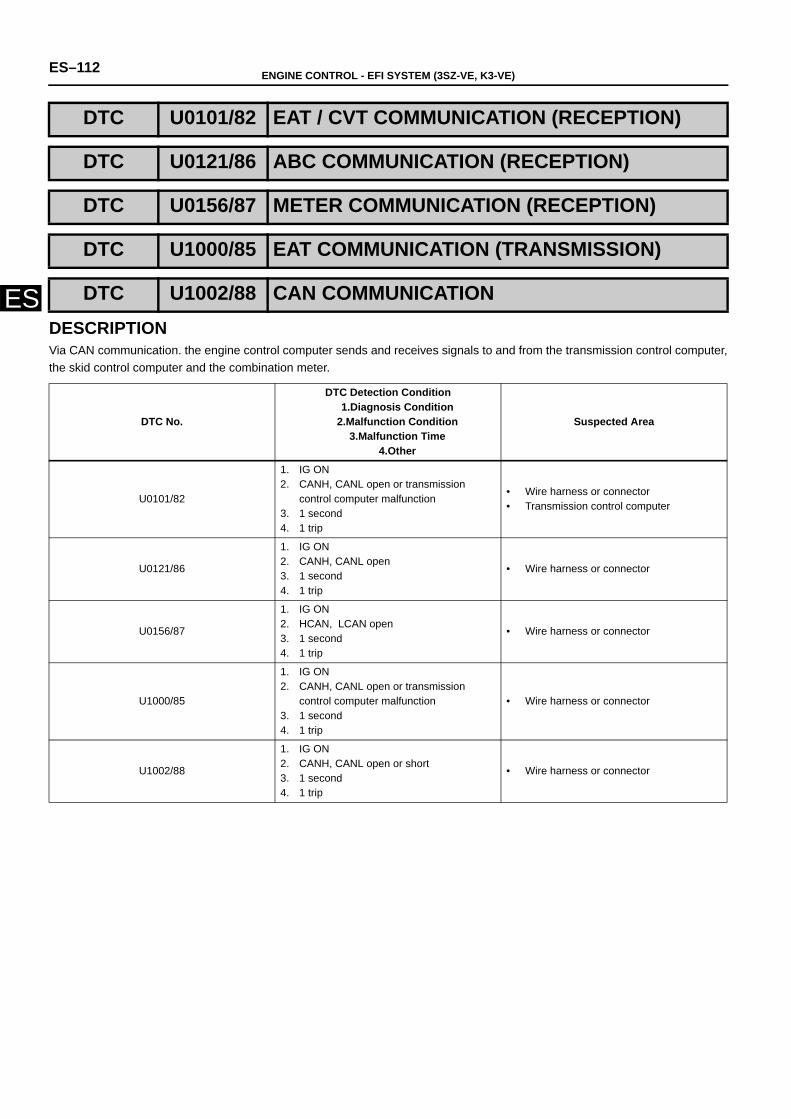
ES–112 ENGINE CONTROL - EFI SYSTEM (3SZ-VE, K3-VE)
ESDESCRIPTIONVia CAN communication. the engine control computer sends and receives signals to and from the transmission control computer,the skid control computer and the combination meter.
DTC U0101/82 EAT / CVT COMMUNICATION (RECEPTION)
DTC U0121/86 ABC COMMUNICATION (RECEPTION)
DTC U0156/87 METER COMMUNICATION (RECEPTION)
DTC U1000/85 EAT COMMUNICATION (TRANSMISSION)
DTC U1002/88 CAN COMMUNICATION
DTC No.
DTC Detection Condition1.Diagnosis Condition
2.Malfunction Condition3.Malfunction Time
4.Other
Suspected Area
U0101/82
1. IG ON2. CANH, CANL open or transmission
control computer malfunction3. 1 second 4. 1 trip
• Wire harness or connector• Transmission control computer
U0121/86
1. IG ON2. CANH, CANL open3. 1 second4. 1 trip
• Wire harness or connector
U0156/87
1. IG ON2. HCAN, LCAN open3. 1 second 4. 1 trip
• Wire harness or connector
U1000/85
1. IG ON2. CANH, CANL open or transmission
control computer malfunction3. 1 second 4. 1 trip
• Wire harness or connector
U1002/88
1. IG ON2. CANH, CANL open or short 3. 1 second 4. 1 trip
• Wire harness or connector
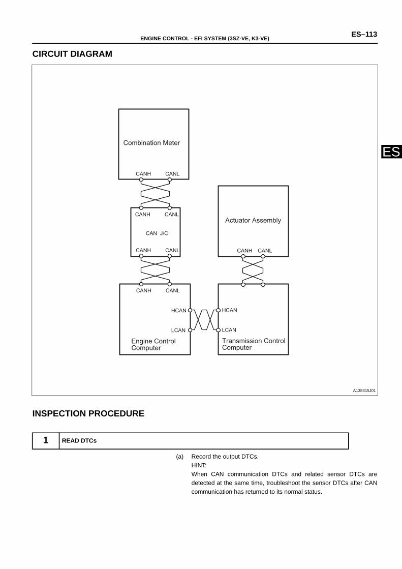
ENGINE CONTROL - EFI SYSTEM (3SZ-VE, K3-VE) ES–113
ES
CIRCUIT DIAGRAM
INSPECTION PROCEDURE
(a) Record the output DTCs.HINT:When CAN communication DTCs and related sensor DTCs aredetected at the same time, troubleshoot the sensor DTCs after CANcommunication has returned to its normal status.
1 READ DTCs
Combination Meter
Actuator Assembly
Engine Control Computer
Transmission Control Computer
CAN J/C
CANH CANL
CANH CANL
CANH CANL
CANH CANL
CANH CANL
HCAN
LCAN
HCAN
LCAN
A138315J01

ES–114 ENGINE CONTROL - EFI SYSTEM (3SZ-VE, K3-VE)
ES
GO TO TROUBLESHOOTING FOR CAN COMMUNICATION SYSTEM

ENGINE CONTROL - EFI SYSTEM (3SZ-VE, K3-VE) ES–115
ES
DESCRIPTIONWhile the engine cranks, current flows from the ST terminal of the ignition switch to the starter relay coil, and from the ST terminalto the STSW terminal (STSW signal) of the engine control computer. When the STSW signal and N1 signal are input to theengine control computer, current flows to the fuel pump relay coil via an internal transistor. This turns the relay switch turns ON.The fuel pump receives current and operates. While N1 is input (with the engine running), the fuel pump continues to operatebecause the transistor switch inside the engine control computer remains ON (F/P relay ON).
CIRCUIT DIAGRAM
FUEL PUMP CONTROL SYSTEM
M
E/G
AM2 EFI
MAIN
35
39
N1-
N1+
STSW
MRO
FC1
Ignition Switch
F/P Relay
EFI Relay
Battery
Fuel Pump
* : FAN 2 For Europe
From Starter Circuit
From Crankshaft Sensor
Engine Control Computer
*
A138423J01
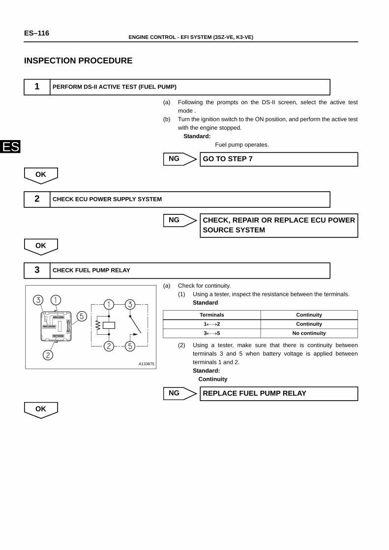
ES–116 ENGINE CONTROL - EFI SYSTEM (3SZ-VE, K3-VE)
ES
INSPECTION PROCEDURE
(a) Following the prompts on the DS-II screen, select the active testmode .
(b) Turn the ignition switch to the ON position, and perform the active testwith the engine stopped.
Standard:Fuel pump operates.
NG
OK
NG
OK
(a) Check for continuity.(1) Using a tester, inspect the resistance between the terminals.
Standard
(2) Using a tester, make sure that there is continuity betweenterminals 3 and 5 when battery voltage is applied betweenterminals 1 and 2.Standard:
Continuity
NG
OK
1 PERFORM DS-II ACTIVE TEST (FUEL PUMP)
GO TO STEP 7
2 CHECK ECU POWER SUPPLY SYSTEM
CHECK, REPAIR OR REPLACE ECU POWERSOURCE SYSTEM
3 CHECK FUEL PUMP RELAY
A133875
Terminals Continuity
1←→2 Continuity
3←→5 No continuity
REPLACE FUEL PUMP RELAY
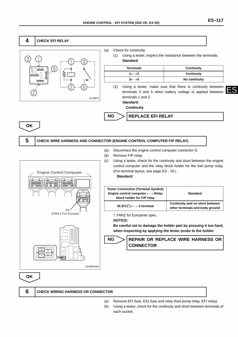
ENGINE CONTROL - EFI SYSTEM (3SZ-VE, K3-VE) ES–117
ES
(a) Check for continuity.(1) Using a tester, inspect the resistance between the terminals.
Standard
(2) Using a tester, make sure that there is continuity betweenterminals 3 and 5 when battery voltage is applied betweenterminals 1 and 2.Standard:
Continuity
NG
OK
(a) Disconnect the engine control computer connector D.(b) Remove F/P relay.(c) Using a tester, check for the continuity and short between the engine
control computer and the relay block holder for the fuel pump relay.(For terminal layout, see page ES - 16.)
Standard:
*: FAN2 for European spec.NOTICE:Be careful not to damage the holder part by pressing it too hard,when inspecting by applying the tester probe to the holder.
NG
OK
(a) Remove EFI fuse, E/G fuse and relay (fuel pump relay, EFI relay).(b) Using a tester, check for the continuity and short between terminals of
each socket.
4 CHECK EFI RELAY
A133875
Terminals Continuity
1←→2 Continuity
3←→5 No continuity
REPLACE EFI RELAY
5 CHECK WIRE HARNESS AND CONNECTOR (ENGINE CONTROL COMPUTER F/P RELAY)
1
25 3
Engine Control Computer
(FAN 2 For Europe)FC
A133876J02
Tester Connection (Terminal Symbol)Engine control computer ←→ Relay
block holder for F/P relay Standard
35 (FC1*) ←→ 3 terminalContinuity and no short between other terminals and body ground
REPAIR OR REPLACE WIRE HARNESS ORCONNECTOR
6 CHECK WIRING HARNESS OR CONNECTOR
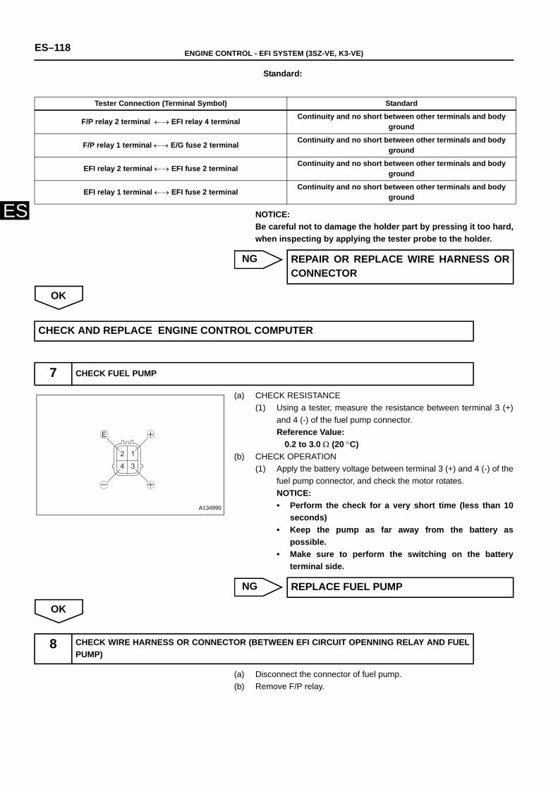
ES–118 ENGINE CONTROL - EFI SYSTEM (3SZ-VE, K3-VE)
ES
Standard:
NOTICE:Be careful not to damage the holder part by pressing it too hard,when inspecting by applying the tester probe to the holder.
NG
OK
(a) CHECK RESISTANCE(1) Using a tester, measure the resistance between terminal 3 (+)
and 4 (-) of the fuel pump connector.Reference Value:
0.2 to 3.0 Ω (20 °C)(b) CHECK OPERATION
(1) Apply the battery voltage between terminal 3 (+) and 4 (-) of thefuel pump connector, and check the motor rotates. NOTICE:• Perform the check for a very short time (less than 10
seconds)• Keep the pump as far away from the battery as
possible.• Make sure to perform the switching on the battery
terminal side.
NG
OK
(a) Disconnect the connector of fuel pump. (b) Remove F/P relay.
Tester Connection (Terminal Symbol) Standard
F/P relay 2 terminal ←→ EFI relay 4 terminal Continuity and no short between other terminals and body ground
F/P relay 1 terminal ←→ E/G fuse 2 terminal Continuity and no short between other terminals and body ground
EFI relay 2 terminal ←→ EFI fuse 2 terminal Continuity and no short between other terminals and body ground
EFI relay 1 terminal ←→ EFI fuse 2 terminal Continuity and no short between other terminals and body ground
REPAIR OR REPLACE WIRE HARNESS ORCONNECTOR
CHECK AND REPLACE ENGINE CONTROL COMPUTER
7 CHECK FUEL PUMP
12
34
E
A134990
REPLACE FUEL PUMP
8 CHECK WIRE HARNESS OR CONNECTOR (BETWEEN EFI CIRCUIT OPENNING RELAY AND FUELPUMP)
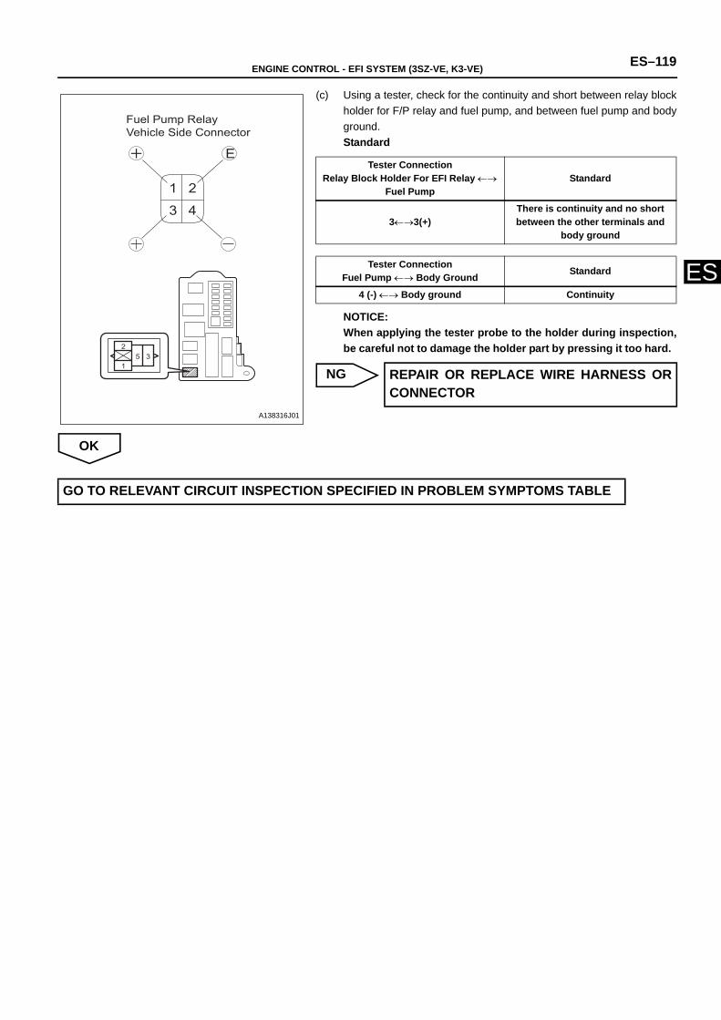
ENGINE CONTROL - EFI SYSTEM (3SZ-VE, K3-VE) ES–119
ES
(c) Using a tester, check for the continuity and short between relay blockholder for F/P relay and fuel pump, and between fuel pump and bodyground.Standard
NOTICE:When applying the tester probe to the holder during inspection,be careful not to damage the holder part by pressing it too hard.
NG
OK
1
25 3
1 2
3 4
E
Fuel Pump Relay Vehicle Side Connector
A138316J01
Tester ConnectionRelay Block Holder For EFI Relay ←→
Fuel PumpStandard
3←→3(+)There is continuity and no short between the other terminals and
body ground
Tester ConnectionFuel Pump ←→ Body Ground Standard
4 (-) ←→ Body ground Continuity
REPAIR OR REPLACE WIRE HARNESS ORCONNECTOR
GO TO RELEVANT CIRCUIT INSPECTION SPECIFIED IN PROBLEM SYMPTOMS TABLE
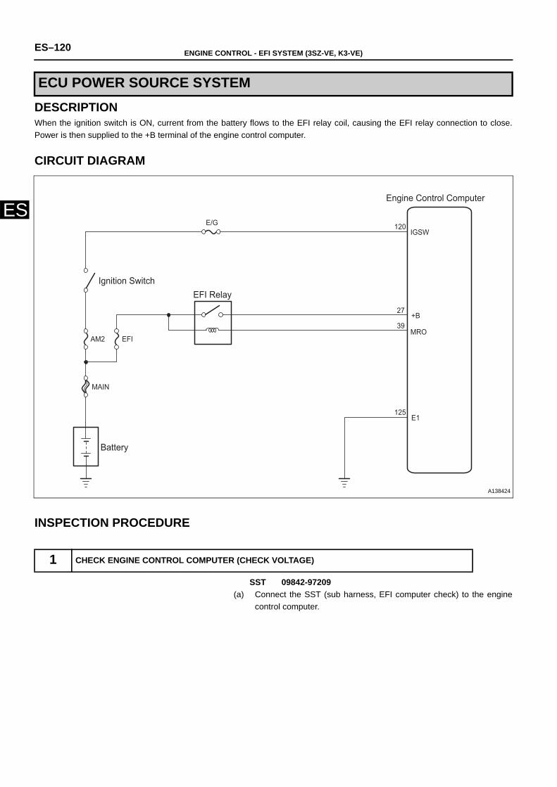
ES–120 ENGINE CONTROL - EFI SYSTEM (3SZ-VE, K3-VE)
ES
DESCRIPTIONWhen the ignition switch is ON, current from the battery flows to the EFI relay coil, causing the EFI relay connection to close.Power is then supplied to the +B terminal of the engine control computer.
CIRCUIT DIAGRAM
INSPECTION PROCEDURE
SST 09842-97209(a) Connect the SST (sub harness, EFI computer check) to the engine
control computer.
ECU POWER SOURCE SYSTEM
1 CHECK ENGINE CONTROL COMPUTER (CHECK VOLTAGE)
E/G
AM2 EFI
MAIN
39MRO
IGSW
+B
E1
120
27
125
Engine Control Computer
Ignition Switch EFI Relay
Battery
A138424
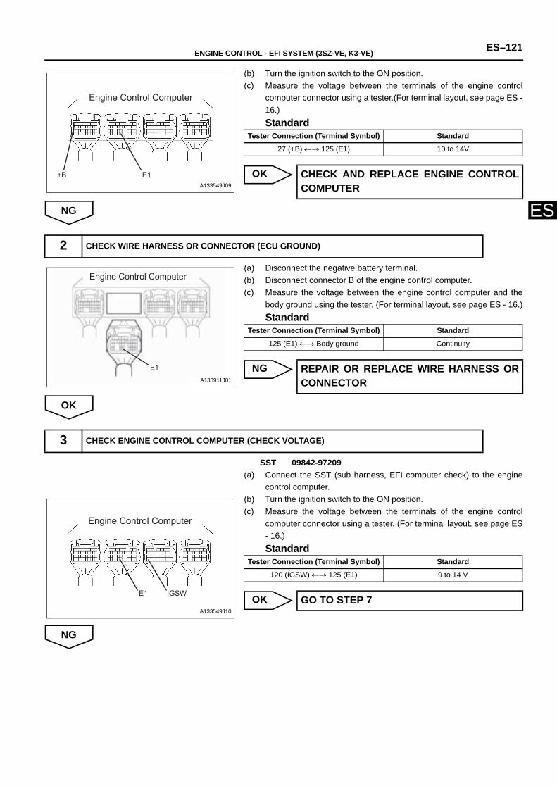
ENGINE CONTROL - EFI SYSTEM (3SZ-VE, K3-VE) ES–121
ES
(b) Turn the ignition switch to the ON position.(c) Measure the voltage between the terminals of the engine control
computer connector using a tester.(For terminal layout, see page ES -16.)Standard
OK
NG
(a) Disconnect the negative battery terminal.(b) Disconnect connector B of the engine control computer.(c) Measure the voltage between the engine control computer and the
body ground using the tester. (For terminal layout, see page ES - 16.)Standard
NG
OK
SST 09842-97209(a) Connect the SST (sub harness, EFI computer check) to the engine
control computer. (b) Turn the ignition switch to the ON position.(c) Measure the voltage between the terminals of the engine control
computer connector using a tester. (For terminal layout, see page ES- 16.)Standard
OK
NG
Engine Control Computer
+B E1A133549J09
Tester Connection (Terminal Symbol) Standard
27 (+B) ←→ 125 (E1) 10 to 14V
CHECK AND REPLACE ENGINE CONTROLCOMPUTER
2 CHECK WIRE HARNESS OR CONNECTOR (ECU GROUND)
Engine Control Computer
E1A133911J01
Tester Connection (Terminal Symbol) Standard
125 (E1) ←→ Body ground Continuity
REPAIR OR REPLACE WIRE HARNESS ORCONNECTOR
3 CHECK ENGINE CONTROL COMPUTER (CHECK VOLTAGE)
E1 IGSW
Engine Control Computer
A133549J10
Tester Connection (Terminal Symbol) Standard
120 (IGSW) ←→ 125 (E1) 9 to 14 V
GO TO STEP 7
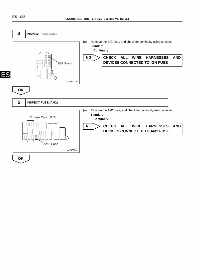
ES–122 ENGINE CONTROL - EFI SYSTEM (3SZ-VE, K3-VE)
ES
(a) Remove the E/G fuse, and check for continuity using a tester. Standard:
Continuity
NG
OK
(a) Remove the AM2 fuse, and check for continuity using a tester. Standard:
Continuity
NG
OK
4 INSPECT FUSE (E/G)
E/G Fuse
A133912J01
CHECK ALL WIRE HARNESSES ANDDEVICES CONNECTED TO IGN FUSE
5 INSPECT FUSE (AM2)
Engine Room R/B
AM2 Fuse
A134899J01
CHECK ALL WIRE HARNESSES ANDDEVICES CONNECTED TO AM2 FUSE
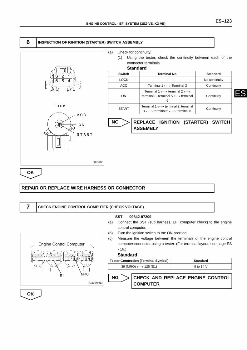
ENGINE CONTROL - EFI SYSTEM (3SZ-VE, K3-VE) ES–123
ES
(a) Check for continuity.(1) Using the tester, check the continuity between each of the
connecter terminals.Standard
NG
OK
SST 09842-97209(a) Connect the SST (sub harness, EFI computer check) to the engine
control computer. (b) Turn the ignition switch to the ON position.(c) Measure the voltage between the terminals of the engine control
computer connector using a tester. (For terminal layout, see page ES- 16.)Standard
NG
OK
6 INSPECTION OF IGNITION (STARTER) SWITCH ASSEMBLY
B059612
Switch Terminal No. Standard
LOCK - No continuity
ACC Terminal 1 ←→ Terminal 3 Continuity
ONTerminal 1 ←→ terminal 2 ←→
terminal 3, terminal 5 ←→ terminal 6
Continuity
STARTTerminal 1 ←→ terminal 2, terminal
4 ←→ terminal 5 ←→ terminal 6 Continuity
REPLACE IGNITION (STARTER) SWITCHASSEMBLY
REPAIR OR REPLACE WIRE HARNESS OR CONNECTOR
7 CHECK ENGINE CONTROL COMPUTER (CHECK VOLTAGE)
Engine Control Computer
E1 MRO
A133549J13
Tester Connection (Terminal Symbol) Standard
39 (MRO) ←→ 125 (E1) 9 to 14 V
CHECK AND REPLACE ENGINE CONTROLCOMPUTER
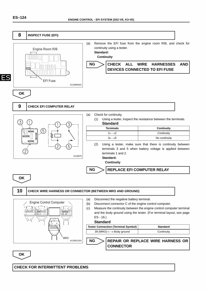
ES–124 ENGINE CONTROL - EFI SYSTEM (3SZ-VE, K3-VE)
ES
(a) Remove the EFI fuse from the engine room R/B, and check forcontinuity using a tester. Standard:
Continuity
NG
OK
(a) Check for continuity.(1) Using a tester, inspect the resistance between the terminals.
Standard
(2) Using a tester, make sure that there is continuity betweenterminals 3 and 5 when battery voltage is applied betweenterminals 1 and 2.Standard:
Continuity
NG
OK
(a) Disconnect the negative battery terminal.(b) Disconnect connector C of the engine control computer.(c) Measure the continuity between the engine control computer terminal
and the body ground using the tester. (For terminal layout, see pageES - 16.)Standard
NG
OK
8 INSPECT FUSE (EFI)
Engine Room R/B
EFI FuseA133909J01
CHECK ALL WIRE HARNESSES ANDDEVICES CONNECTED TO EFI FUSE
9 CHECK EFI COMPUTER RELAY
A133875
Terminals Continuity
1←→2 Continuity
3←→5 No continuity
REPLACE EFI COMPUTER RELAY
10 CHECK WIRE HARNESS OR CONNECTOR (BETWEEN MRO AND GROUND)
Engine Control Computer
MROA133913J01
Tester Connection (Terminal Symbol) Standard
39 (MRO) ←→ Body ground Continuity
REPAIR OR REPLACE WIRE HARNESS ORCONNECTOR
CHECK FOR INTERMITTENT PROBLEMS
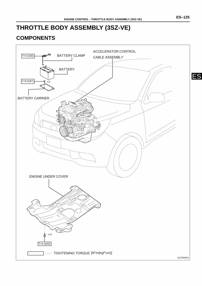
ENGINE CONTROL - THROTTLE BODY ASSEMBLY (3SZ-VE) ES–125
ES
ENGINEENGINE CONTROLTHROTTLE BODY ASSEMBLY (3SZ-VE)COMPONENTS
[N*mkgf*cm]TIGHTENING TORQUE
T=3.536 BATTERY CLAMP
BATTERY
×3T=8.587
BATTERY CARRIER
ACCELERATOR CONTROL
CABLE ASSEMBLY
ENGINE UNDER COVER
×11
T=5.455
A137009J01
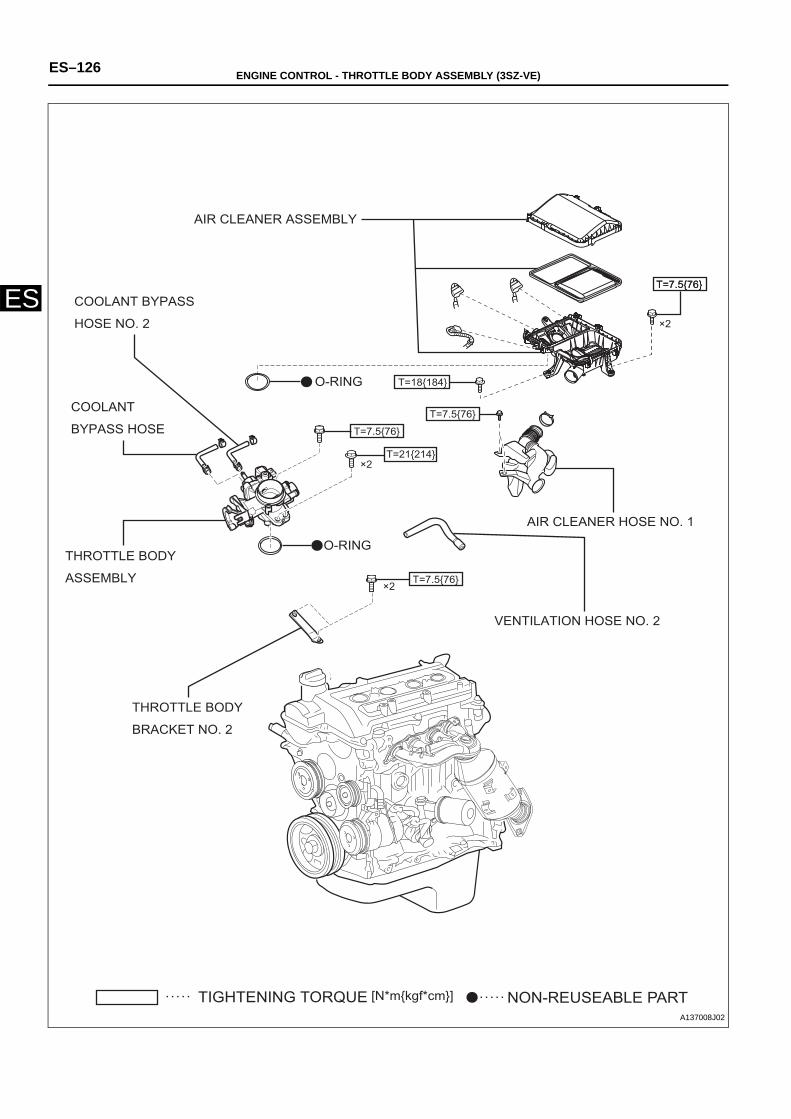
ES–126 ENGINE CONTROL - THROTTLE BODY ASSEMBLY (3SZ-VE)
ES
[N*mkgf*cm]TIGHTENING TORQUE NON-REUSEABLE PART
AIR CLEANER ASSEMBLY
×2
T=7.576T=7.576
T=18184
T=7.576
AIR CLEANER HOSE NO. 1
VENTILATION HOSE NO. 2
T=21214×2
T=7.576
×2T=7.576
O-RING
O-RING
COOLANT BYPASS
HOSE NO. 2
COOLANT
BYPASS HOSE
THROTTLE BODY
ASSEMBLY
THROTTLE BODY
BRACKET NO. 2
A137008J02
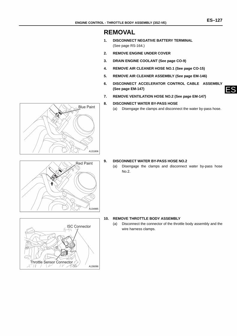
ENGINE CONTROL - THROTTLE BODY ASSEMBLY (3SZ-VE) ES–127
ES
REMOVAL1. DISCONNECT NEGATIVE BATTERY TERMINAL
(See page RS-164.)
2. REMOVE ENGINE UNDER COVER
3. DRAIN ENGINE COOLANT (See page CO-9)
4. REMOVE AIR CLEANER HOSE NO.1 (See page CO-15)
5. REMOVE AIR CLEANER ASSEMBLY (See page EM-146)
6. DISCONNECT ACCELERATOR CONTROL CABLE ASSEMBLY(See page EM-147)
7. REMOVE VENTILATION HOSE NO.2 (See page EM-147)
8. DISCONNECT WATER BY-PASS HOSE (a) Disengage the clamps and disconnect the water by-pass hose.
9. DISCONNECT WATER BY-PASS HOSE NO.2 (a) Disengage the clamps and disconnect water by-pass hose
No.2.
10. REMOVE THROTTLE BODY ASSEMBLY(a) Disconnect the connector of the throttle body assembly and the
wire harness clamps.
Blue Paint
A131806
Red Paint
A134985
Throttle Sensor Connector
ISC Connector
A136086
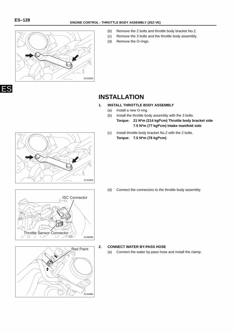
ES–128 ENGINE CONTROL - THROTTLE BODY ASSEMBLY (3SZ-VE)
ES
(b) Remove the 2 bolts and throttle body bracket No.2. (c) Remove the 3 bolts and the throttle body assembly. (d) Remove the O-rings.
INSTALLATION1. INSTALL THROTTLE BODY ASSEMBLY
(a) Install a new O-ring.(b) Install the throttle body assembly with the 3 bolts.
Torque: 21 N*m (214 kgf*cm) Throttle body bracket side7.5 N*m (77 kgf*cm) Intake manifold side
(c) Install throttle body bracket No.2 with the 2 bolts.Torque: 7.5 N*m (76 kgf*cm)
(d) Connect the connectors to the throttle body assembly.
2. CONNECT WATER BY-PASS HOSE(a) Connect the water by-pass hose and install the clamp.
A131805
A131805
Throttle Sensor Connector
ISC Connector
A136086
Red Paint
A134985
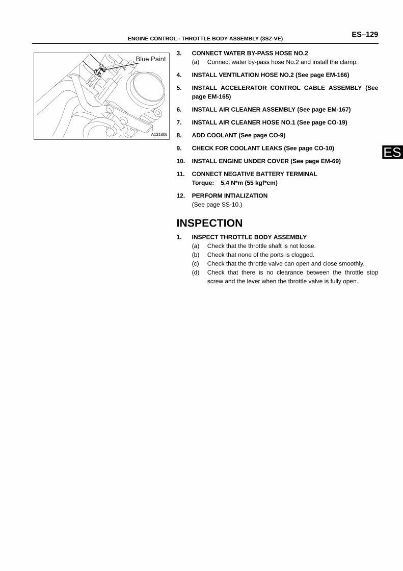
ENGINE CONTROL - THROTTLE BODY ASSEMBLY (3SZ-VE) ES–129
ES
3. CONNECT WATER BY-PASS HOSE NO.2 (a) Connect water by-pass hose No.2 and install the clamp.
4. INSTALL VENTILATION HOSE NO.2 (See page EM-166)
5. INSTALL ACCELERATOR CONTROL CABLE ASSEMBLY (Seepage EM-165)
6. INSTALL AIR CLEANER ASSEMBLY (See page EM-167)
7. INSTALL AIR CLEANER HOSE NO.1 (See page CO-19)
8. ADD COOLANT (See page CO-9)
9. CHECK FOR COOLANT LEAKS (See page CO-10)
10. INSTALL ENGINE UNDER COVER (See page EM-69)
11. CONNECT NEGATIVE BATTERY TERMINALTorque: 5.4 N*m (55 kgf*cm)
12. PERFORM INTIALIZATION(See page SS-10.)
INSPECTION1. INSPECT THROTTLE BODY ASSEMBLY
(a) Check that the throttle shaft is not loose.(b) Check that none of the ports is clogged.(c) Check that the throttle valve can open and close smoothly.(d) Check that there is no clearance between the throttle stop
screw and the lever when the throttle valve is fully open.
Blue Paint
A131806
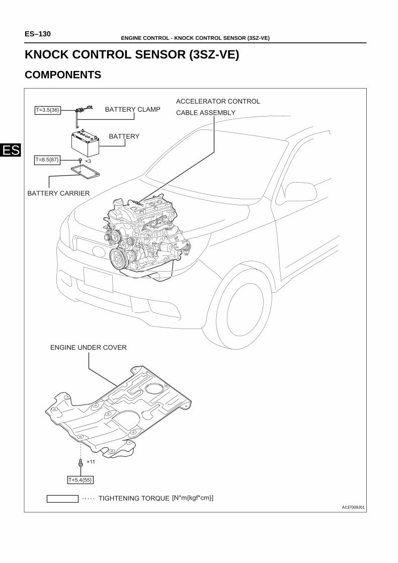
ES–130 ENGINE CONTROL - KNOCK CONTROL SENSOR (3SZ-VE)
ES
ENGINEENGINE CONTROLKNOCK CONTROL SENSOR (3SZ-VE)COMPONENTS
[N*mkgf*cm]TIGHTENING TORQUE
T=3.536 BATTERY CLAMP
BATTERY
×3T=8.587
BATTERY CARRIER
ACCELERATOR CONTROL
CABLE ASSEMBLY
ENGINE UNDER COVER
×11
T=5.455
A137009J01
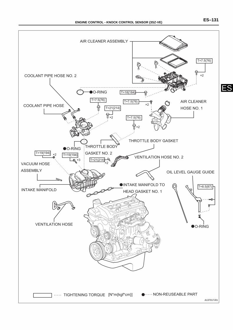
ENGINE CONTROL - KNOCK CONTROL SENSOR (3SZ-VE) ES–131
ES
[N*mkgf*cm]TIGHTENING TORQUE NON-REUSEABLE PART
AIR CLEANER ASSEMBLY
T=18184
×2T=7.576T=7.576
O-RING
T=21214
×2
THROTTLE BODY
GASKET NO. 2
T=7.576
×2
AIR CLEANER
HOSE NO. 1
×2
T=7.576
THROTTLE BODY GASKET
VENTILATION HOSE NO. 2
OIL LEVEL GAUGE GUIDE
T=8.587
O-RING
INTAKE MANIFOLD TO
HEAD GASKET NO. 1
×2T=21214
O-RINGT=19194
×3
×2
VACUUM HOSE
ASSEMBLY
INTAKE MANIFOLD
VENTILATION HOSE
COOLANT PIPE HOSE NO. 2
COOLANT PIPE HOSE
T=19194
A137017J01
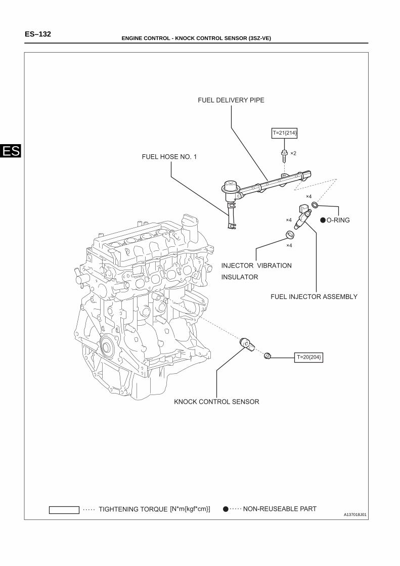
ES–132 ENGINE CONTROL - KNOCK CONTROL SENSOR (3SZ-VE)
ES
[N*mkgf*cm]TIGHTENING TORQUE NON-REUSEABLE PART
T=21214
T=20204
×2
×4
×4
×4
FUEL DELIVERY PIPE
FUEL HOSE NO. 1
INJECTOR VIBRATION
INSULATOR
FUEL INJECTOR ASSEMBLY
KNOCK CONTROL SENSOR
O-RING
A137018J01
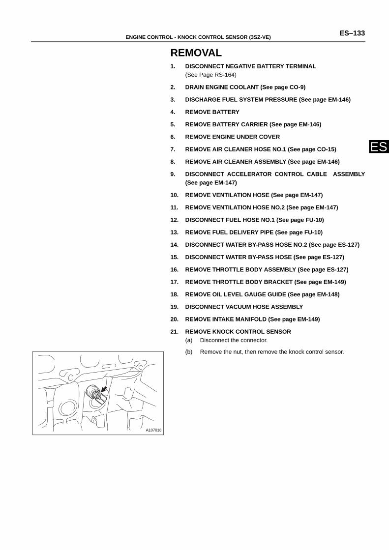
ENGINE CONTROL - KNOCK CONTROL SENSOR (3SZ-VE) ES–133
ES
REMOVAL1. DISCONNECT NEGATIVE BATTERY TERMINAL
(See Page RS-164)
2. DRAIN ENGINE COOLANT (See page CO-9)
3. DISCHARGE FUEL SYSTEM PRESSURE (See page EM-146)
4. REMOVE BATTERY
5. REMOVE BATTERY CARRIER (See page EM-146)
6. REMOVE ENGINE UNDER COVER
7. REMOVE AIR CLEANER HOSE NO.1 (See page CO-15)
8. REMOVE AIR CLEANER ASSEMBLY (See page EM-146)
9. DISCONNECT ACCELERATOR CONTROL CABLE ASSEMBLY(See page EM-147)
10. REMOVE VENTILATION HOSE (See page EM-147)
11. REMOVE VENTILATION HOSE NO.2 (See page EM-147)
12. DISCONNECT FUEL HOSE NO.1 (See page FU-10)
13. REMOVE FUEL DELIVERY PIPE (See page FU-10)
14. DISCONNECT WATER BY-PASS HOSE NO.2 (See page ES-127)
15. DISCONNECT WATER BY-PASS HOSE (See page ES-127)
16. REMOVE THROTTLE BODY ASSEMBLY (See page ES-127)
17. REMOVE THROTTLE BODY BRACKET (See page EM-149)
18. REMOVE OIL LEVEL GAUGE GUIDE (See page EM-148)
19. DISCONNECT VACUUM HOSE ASSEMBLY
20. REMOVE INTAKE MANIFOLD (See page EM-149)
21. REMOVE KNOCK CONTROL SENSOR (a) Disconnect the connector.
(b) Remove the nut, then remove the knock control sensor.
A107018
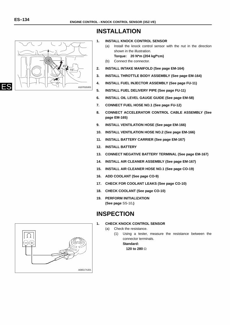
ES–134 ENGINE CONTROL - KNOCK CONTROL SENSOR (3SZ-VE)
ES
INSTALLATION1. INSTALL KNOCK CONTROL SENSOR
(a) Install the knock control sensor with the nut in the directionshown in the illustration. Torque: 20 N*m (204 kgf*cm)
(b) Connect the connector.
2. INSTALL INTAKE MANIFOLD (See page EM-164)
3. INSTALL THROTTLE BODY ASSEMBLY (See page EM-164)
4. INSTALL FUEL INJECTOR ASSEMBLY (See page FU-11)
5. INSTALL FUEL DELIVERY PIPE (See page FU-11)
6. INSTALL OIL LEVEL GAUGE GUIDE (See page EM-58)
7. CONNECT FUEL HOSE NO.1 (See page FU-12)
8. CONNECT ACCELERATOR CONTROL CABLE ASSEMBLY (Seepage EM-165)
9. INSTALL VENTILATION HOSE (See page EM-166)
10. INSTALL VENTILATION HOSE NO.2 (See page EM-166)
11. INSTALL BATTERY CARRIER (See page EM-167)
12. INSTALL BATTERY
13. CONNECT NEGATIVE BATTERY TERMINAL (See page EM-167)
14. INSTALL AIR CLEANER ASSEMBLY (See page EM-167)
15. INSTALL AIR CLEANER HOSE NO.1 (See page CO-19)
16. ADD COOLANT (See page CO-9)
17. CHECK FOR COOLANT LEAKS (See page CO-10)
18. CHECK COOLANT (See page CO-10)
19. PERFORM INITIALIZATION(See page SS-10.)
INSPECTION1. CHECK KNOCK CONTROL SENSOR
(a) Check the resistance.(1) Using a tester, measure the resistance between the
connector terminals.Standard:
120 to 280 Ω
45°15°
15°A107019J01
A065174J01

ENGINE CONTROL - CAMSHAFT TIMING OIL CONTROL VALVE ASSEMBLY (3SZ-VE) ES–135
ES
ENGINEENGINE CONTROLCAMSHAFT TIMING OIL CONTROL VALVE ASSEMBLY(3SZ-VE)COMPONENTS
CAMSHAFT TIMING OIL CONTROL VALVE ASSEMBLY
O-RING
T=7.576
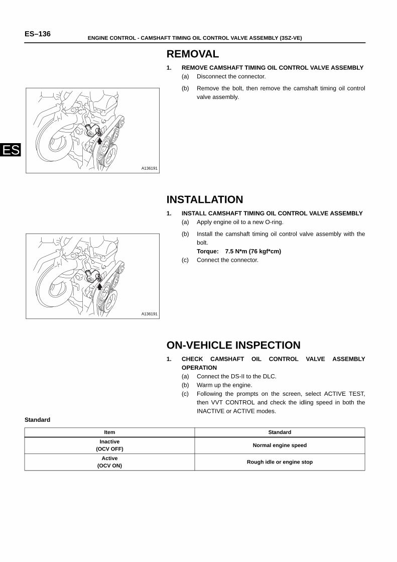
ES–136 ENGINE CONTROL - CAMSHAFT TIMING OIL CONTROL VALVE ASSEMBLY (3SZ-VE)
ES
REMOVAL1. REMOVE CAMSHAFT TIMING OIL CONTROL VALVE ASSEMBLY
(a) Disconnect the connector.
(b) Remove the bolt, then remove the camshaft timing oil controlvalve assembly.
INSTALLATION1. INSTALL CAMSHAFT TIMING OIL CONTROL VALVE ASSEMBLY
(a) Apply engine oil to a new O-ring.
(b) Install the camshaft timing oil control valve assembly with thebolt.Torque: 7.5 N*m (76 kgf*cm)
(c) Connect the connector.
ON-VEHICLE INSPECTION1. CHECK CAMSHAFT OIL CONTROL VALVE ASSEMBLY
OPERATION(a) Connect the DS-II to the DLC.(b) Warm up the engine.(c) Following the prompts on the screen, select ACTIVE TEST,
then VVT CONTROL and check the idling speed in both theINACTIVE or ACTIVE modes.
Standard
A136191
A136191
Item Standard
Inactive (OCV OFF) Normal engine speed
Active (OCV ON) Rough idle or engine stop
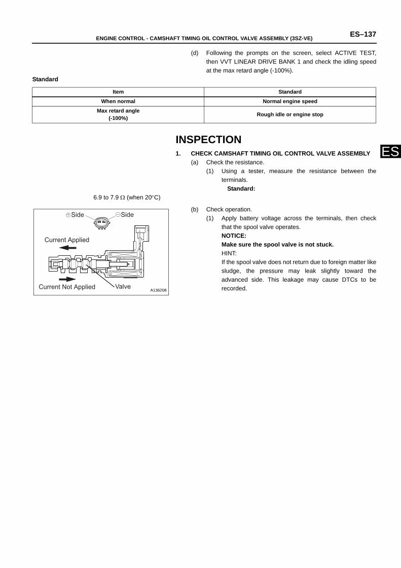
ENGINE CONTROL - CAMSHAFT TIMING OIL CONTROL VALVE ASSEMBLY (3SZ-VE) ES–137
ES
(d) Following the prompts on the screen, select ACTIVE TEST,then VVT LINEAR DRIVE BANK 1 and check the idling speedat the max retard angle (-100%).
Standard
INSPECTION1. CHECK CAMSHAFT TIMING OIL CONTROL VALVE ASSEMBLY
(a) Check the resistance.(1) Using a tester, measure the resistance between the
terminals.Standard:
6.9 to 7.9 Ω (when 20°C)
(b) Check operation.(1) Apply battery voltage across the terminals, then check
that the spool valve operates.NOTICE:Make sure the spool valve is not stuck.HINT:If the spool valve does not return due to foreign matter likesludge, the pressure may leak slightly toward theadvanced side. This leakage may cause DTCs to berecorded.
Item Standard
When normal Normal engine speed
Max retard angle(-100%) Rough idle or engine stop
Side Side
Valve Current Not Applied
Current Applied
A136208
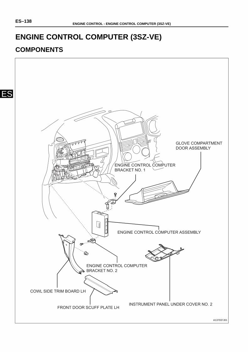
ES–138 ENGINE CONTROL - ENGINE CONTROL COMPUTER (3SZ-VE)
ES
ENGINEENGINE CONTROLENGINE CONTROL COMPUTER (3SZ-VE)COMPONENTS
GLOVE COMPARTMENT DOOR ASSEMBLY
ENGINE CONTROL COMPUTER BRACKET NO. 1
ENGINE CONTROL COMPUTER ASSEMBLY
ENGINE CONTROL COMPUTER BRACKET NO. 2
COWL SIDE TRIM BOARD LH
FRONT DOOR SCUFF PLATE LHINSTRUMENT PANEL UNDER COVER NO. 2
A137037J01
ENGINE CONTROL - ENGINE CONTROL COMPUTER (3SZ-VE) ES–139
ES
REMOVAL1. DISCONNECT NEGATIVE BATTERY TERMINAL
(See page RS-164.)
2. REMOVE GLOVE COMPARTMENT DOOR ASSEMBLY ( See pageIP-11)
3. INSTALL INSTRUMENT PANEL UNDER COVER NO.2 ( See pageIP-12)
4. REMOVE FRONT DOOR SCUFF PLATE LH
5. REMOVE COWL SIDE TRIM BOARD LH
6. REMOVE ENGINE CONTROL COMPUTER (a) Remove each connector. (b) Remove the 2 bolts and the engine control computer.
NOTICE: Be careful not to drop the engine control computer.
7. REMOVE ENGINE CONTROL COMPUTER BRACKET NO.1(a) Disengage the claw and remove engine control computer
bracket No.1 from the engine control computer.
8. REMOVE ENGINE CONTROL COMPUTER BRACKET NO.2(a) Disengage the claw and remove engine control computer
bracket No.2 from the engine control computer.
INSTALLATION1. INSTALL ENGINE CONTROL COMPUTER BRACKET NO.2
(a) Install engine control computer bracket No.2 to the enginecontrol computer.
2. INSTALL ENGINE CONTROL COMPUTER BRACKET NO.1(a) Install engine control computer bracket No.1 to the engine
control computer
3. INSTALL ENGINE CONTROL COMPUTER(a) Install the engine control computer with the 2 bolts.(b) Connect each connector.
4. INSTALL COWL SIDE TRIM BOARD LH
5. INSTALL FRONT DOOR SCUFF PLATE LH
6. INSTALL INSTRUMENT PANEL UNDER COVER NO.2 ( See pageIP-17)
7. INSTALL GLOVE COMPARTMENT DOOR ASSEMBLY ( See pageIP-18)
8. CONNECT NEGATIVE BATTERY TERMINALTorque: 5.4 N*m (55 kgf*cm)
9. PERFORM INITIALIZATION(See page SS-10.)
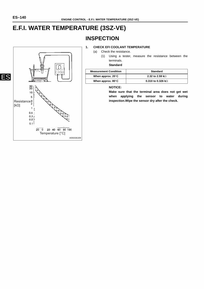
ES–140 ENGINE CONTROL - E.F.I. WATER TEMPERATURE (3SZ-VE)
ES
ENGINEENGINE CONTROLE.F.I. WATER TEMPERATURE (3SZ-VE)INSPECTION1. CHECK EFI COOLANT TEMPERATURE
(a) Check the resistance.(1) Using a tester, measure the resistance between the
terminals.Standard
NOTICE:Make sure that the terminal area does not get wetwhen applying the sensor to water duringinspection.Wipe the sensor dry after the check.Resistance
[kΩ]
Temperature [°C] A050330J09
Measurement Condition Standard
When approx. 20°C 2.32 to 2.59 kΩ
When approx. 80°C 0.310 to 0.326 kΩ
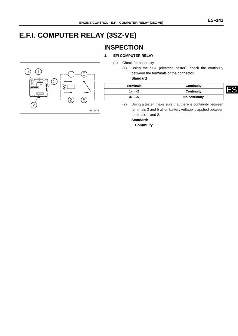
ENGINE CONTROL - E.F.I. COMPUTER RELAY (3SZ-VE) ES–141
ES
ENGINEENGINE CONTROLE.F.I. COMPUTER RELAY (3SZ-VE)INSPECTION1. EFI COMPUTER RELAY
(a) Check for continuity.(1) Using the SST (electrical tester), check the continuity
between the terminals of the connector.Standard
(2) Using a tester, make sure that there is continuity betweenterminals 3 and 5 when battery voltage is applied betweenterminals 1 and 2. Standard:
Continuity
A133875
Terminals Continuity
1←→2 Continuity
3←→5 No continuity
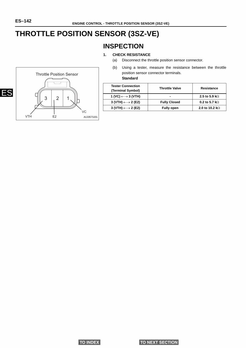
ES–142 ENGINE CONTROL - THROTTLE POSITION SENSOR (3SZ-VE)
ES
ENGINEENGINE CONTROLTHROTTLE POSITION SENSOR (3SZ-VE)INSPECTION1. CHECK RESISTANCE
(a) Disconnect the throttle position sensor connector.
(b) Using a tester, measure the resistance between the throttleposition sensor connector terminals.Standard
123
VTH E2VC
Throttle Position Sensor
A133573J01
Tester Connection (Terminal Symbol) Throttle Valve Resistance
1 (VC) ←→ 3 (VTH) - 2.5 to 5.9 kΩ
3 (VTH) ←→ 2 (E2) Fully Closed 0.2 to 5.7 kΩ
3 (VTH) ←→ 2 (E2) Fully open 2.0 to 10.2 kΩ
TO INDEX TO NEXT SECTION