energuide rating system (ers) v.15...
TRANSCRIPT

ENERGUIDE RATING SYSTEM (ERS) V.15 SUPPLEMENTARY STUDY GUIDE
Foundation Level Exam
Supplementary Study Guide
March 2018
EnerGuide Rating System (ERS) V.15 Supplementary Study Guide
Foundation Level Exam
Ref. No. 8339 ii
Acknowledgment and Disclaimer
This document was prepared with financial support from Ontario’s Independent Electricity System
Operator (IESO).
Natural Resources Canada (NRCan) assisted CIET and Knowenergy in this project by providing publicly
available information on the EnerGuide Rating System program. However, NRCan assistance does not
imply endorsement of this product.
The Canadian Home Builders’ Association (CHBA) kindly agreed to share figures from its Canadian
Home Builder’s Manual.
EnerGuide Rating System (ERS) V.15 Supplementary Study Guide
Foundation Level Exam
Ref. No. 8339 1
Introduction
Energy advisors use the EnerGuide Rating System (ERS) to assess the energy performance and
savings potential of homes at the design, construction and renovation stages. As part of their duties,
energy advisors are required to provide helpful advice to homeowners and builders who want to improve
home energy efficiency. Qualified energy advisors must have the necessary knowledge and experience
in the following areas:
› The EnerGuide Rating System;
› Residential construction practices for low-rise housing, including multi-unit residential
buildings (MURBs);
› Energy efficiency renovation practices;
› Heating, ventilation and air-conditioning (HVAC);
› Building science;
› Basic mathematics, geometry and computer skills;
› Data-collection requirements;
› Energy simulation modelling using HOT2000;
› Good client relations.
To register as an energy advisor under ERS V.15, candidates must meet the following criteria:1
1 Pass the Foundation Level Exam;
2 Pass the EnerGuide Rating System V.15 – Energy Advisor Exam;
3 Be affiliated with at least one licensed service organization;
4 Be registered with Natural Resources Canada by:
- Passing the Foundation Level Exam and the Energy Advisor Exam;
- Completing the probationary files to the satisfaction of the service organization’s quality
assurance specialist;
- Providing proof of a Criminal Record Check to the service organization manager.
To register to deliver EnerGuide Rating System services for MURBs, the energy advisor must:
1 Meet all of the energy advisor requirements listed above;
2 Pass the Multi-Unit Residential Building Exam;
3 Complete the probationary files for multi-unit residential buildings to the satisfaction of the service
organization’s quality assurance specialist.
1 Natural Resources Canada. (2017). Registration Process for an Energy Advisor. Administrative Procedures (Version 15.4) (pp. 18-20). Canada: Natural Resources Canada.

EnerGuide Rating System (ERS) V.15 Supplementary Study Guide
Foundation Level Exam
Ref. No. 8339 2
The service organization is responsible for vetting and ensuring the competency of its energy advisors.
NRCan recommends a set of basic probationary files. However, if deemed necessary by the service
organization, the candidate energy advisor may be required to complete additional files.
NRCan has developed a complete competency profile consisting of a number of learning objectives to
guide candidates in preparation for the exam. The contents herein are intended as a supplementary
study guide to help candidates assess whether they are ready to pass the EnerGuide Rating
System V.15 – Foundation Level Exam (required for energy advisors and quality assurance specialists);
however, it should not be used as a stand-alone resource to prepare for the exam. Candidates should
use this supplementary guide once they believe they are sufficiently prepared to pass the exam. In
addition to using this guide, candidates are encouraged to read the latest version of the references listed
herein and consult the NRCan EnerGuide Rating System V.15 – Foundation Level Exam Competency
Profile, which can be found on this website2.
This study guide focuses on the 38 most challenging learning objectives that have been identified based
on the statistics about the exam-takers’ performance in 2017. It is designed to provide candidates with
a basic summary of each of these 38 objectives and some practice questions. The list of learning
objectives is presented in Table 1.
2 Natural Resources Canada. (2018, 23 March). Become an energy advisor. Retrieved from http://www.nrcan.gc.ca/energy/efficiency/housing/new-homes/16631

EnerGuide Rating System (ERS) V.15 Supplementary Study Guide
Foundation Level Exam
Ref. No. 8339 3
1 Foundation Level Exam
The Foundation Level Exam is intended to test candidates’ foundational knowledge of house
construction. There is no official study document to prepare for the Foundation Level Exam, but NRCan
provides a Foundation Level exam competency profile. There are seven categories of competencies
and 25 subcategories, with a total of over 200 learning objectives. The seven categories are listed
below.
1 Communication and Computer Skills;
2 Numeracy;
3 Construction and Renovation of Low-rise Housing;
4 Safety Considerations;
5 Building Envelope (New and Existing Homes);
6 Heating, Ventilation and Air-conditioning (New and Existing Homes);
7 Building Science Principles and the House-as-a-System Concept.
The range of knowledge required to become a certified energy advisor is wide and covers most of the
elements that influence the energy performance of a house.
The exam consists of 150 questions to be answered within three hours.
1.1 Typical Pitfalls and Tips
One of the most common mistakes made by candidates when preparing for the Foundation Level Exam
is to assume that they already have all the fundamental knowledge needed to pass the exam.
Candidates are strongly advised to carefully prepare for the exam because a lack of preparation is the
main reason for failure.
Those candidates who are not used to these types of exams should prepare more thoroughly to avoid
facing time constraints.
How to Prepare for the EnerGuide Rating System V.15 – Foundation Level Exam
As a first step, candidates should read the Candidate Exam Handbook that contains information on:
› The exam development process.
› How to prepare for the exam.
› How to register for and pay fees to take the exam.
› The exam day procedure.
› The Candidate Statement of Understanding.
EnerGuide Rating System (ERS) V.15 Supplementary Study Guide
Foundation Level Exam
Ref. No. 8339 4
The scope of knowledge required to become a certified energy advisor is wide and covers most
elements that influence home energy performance. For this reason, NRCan provides a list of
competency profiles outlining the learning objectives covered by the File Exchange/EnerGuide Rating
System V.153 required to study for ERS V.15. These profiles provide candidates with the suggested
references for each learning objective. To obtain access to the File Exchange site, please contact
NRCan.
All learning objectives in these competency profiles are important, although some require particular
attention. To help candidates better prepare, NRCan has identified the most challenging 100 learning
objectives which are found in the various competency profile categories. We suggest that candidates
pay special attention when studying these (File Exchange/Support Doc V.15 Exam Foundation Level).3
To help candidates become familiar with exam content, the exam website4 provides a tutorial and
sample quiz that candidates can take after registering at https://nrcan.ysasecure.com/. The 15-minute
sample quiz includes 15 multiple choice questions similar to the ones that are asked in the Foundation
Level Exam and the three EnerGuide Rating System Exams (i.e. ERS V.15 – Energy Advisor Exam,
ERS V.15 – Quality Assurance Specialist Exam, and Service Organization Manager Exam).
Tips
1 Study the documents listed in the References section below;
2 Carefully peruse this study guide;
3 Take the tutorial quiz and the sample quiz well in advance of the exam;
4 Make sure to arrive at the exam venue 30 minutes in advance to get ready;
5 To make the best use of the time allowed, bookmark those questions you are uncertain about.
When facing uncertainty, candidates should use this bookmark feature and move on to other
questions since such questions might become clearer as they progress through the exam.
Candidates may later return to these tougher questions;
6 Most importantly, prepare well and get ready!
3 https://fileexchange.nrcan.gc.ca/ 4 https://nrcan.ysasecure.com/

EnerGuide Rating System (ERS) V.15 Supplementary Study Guide
Foundation Level Exam
Ref. No. 8339 5
1.2 References
Each section of this guide is provided with its own set of references. The following are the three main
consulted resources in preparing this guide.
1 Canadian Home Builders' Association. (2006). Builders’ Manual (6th Edition).
2 Natural Resources Canada. (2017). How your house work. Keeping the Heat In. Retrieved from
http://www.nrcan.gc.ca/sites/www.nrcan.gc.ca/files/energy/pdf/housing/Keeping%20the%20Hea
t%20In_e%20.pdf
3 Canadian Wood-Frame House Construction, the Canadian Mortgage Housing Corporation.
1.3 Warning
To become a qualified and effective energy advisor, candidates must achieve all the learning objectives,
not only the most challenging. This guide is not designed to reduce the amount of preparation by
candidates; rather, it is designed to raise awareness and enhance understanding about the most difficult
sections of the exam.
1.4 Comments and Error Reporting
Please report any mistakes found in the guide or submit comments to
EnerGuide Rating System (ERS) V.15 Supplementary Study Guide
Foundation Level Exam
Ref. No. 8339 6
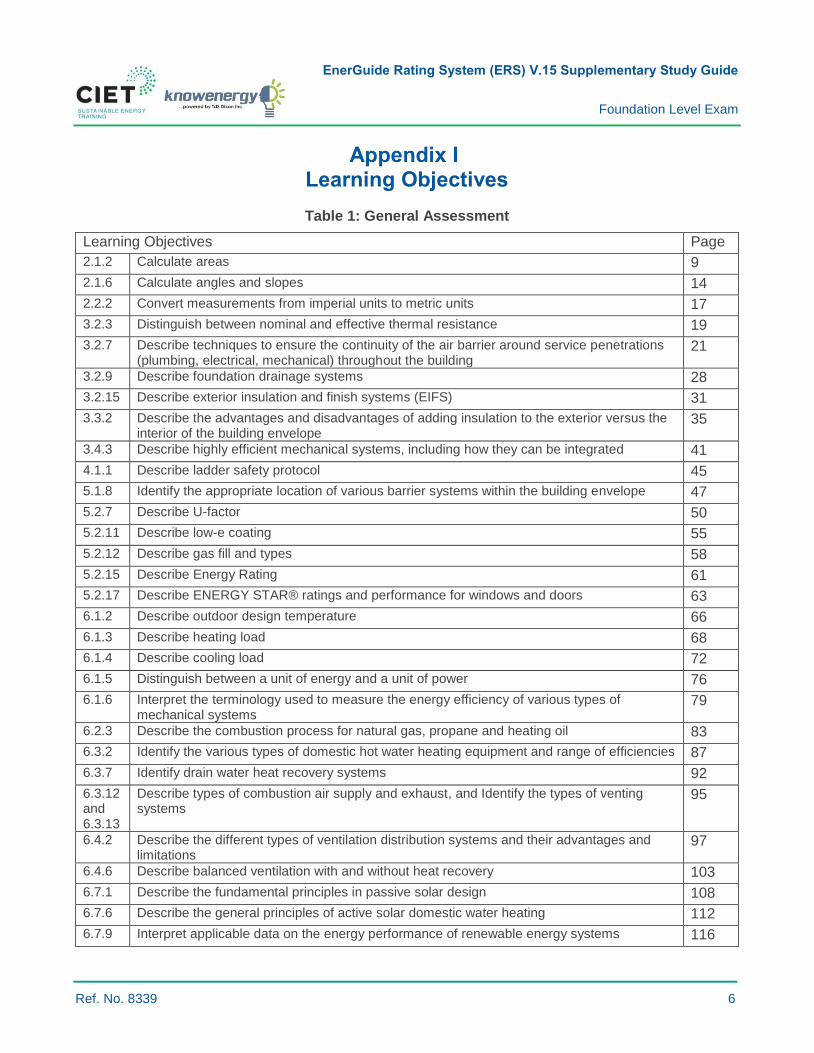
Learning Objectives
Table 1: General Assessment
Learning Objectives Page
2.1.2 Calculate areas 9
2.1.6 Calculate angles and slopes 14
2.2.2 Convert measurements from imperial units to metric units 17
3.2.3 Distinguish between nominal and effective thermal resistance 19
3.2.7 Describe techniques to ensure the continuity of the air barrier around service penetrations (plumbing, electrical, mechanical) throughout the building
21
3.2.9 Describe foundation drainage systems 28
3.2.15 Describe exterior insulation and finish systems (EIFS) 31
3.3.2 Describe the advantages and disadvantages of adding insulation to the exterior versus the interior of the building envelope
35
3.4.3 Describe highly efficient mechanical systems, including how they can be integrated 41
4.1.1 Describe ladder safety protocol 45
5.1.8 Identify the appropriate location of various barrier systems within the building envelope 47
5.2.7 Describe U-factor 50
5.2.11 Describe low-e coating 55
5.2.12 Describe gas fill and types 58
5.2.15 Describe Energy Rating 61
5.2.17 Describe ENERGY STAR® ratings and performance for windows and doors 63
6.1.2 Describe outdoor design temperature 66
6.1.3 Describe heating load 68
6.1.4 Describe cooling load 72
6.1.5 Distinguish between a unit of energy and a unit of power 76
6.1.6 Interpret the terminology used to measure the energy efficiency of various types of mechanical systems
79
6.2.3 Describe the combustion process for natural gas, propane and heating oil 83
6.3.2 Identify the various types of domestic hot water heating equipment and range of efficiencies 87
6.3.7 Identify drain water heat recovery systems 92
6.3.12 and 6.3.13
Describe types of combustion air supply and exhaust, and Identify the types of venting systems
95
6.4.2 Describe the different types of ventilation distribution systems and their advantages and limitations
97
6.4.6 Describe balanced ventilation with and without heat recovery 103
6.7.1 Describe the fundamental principles in passive solar design 108
6.7.6 Describe the general principles of active solar domestic water heating 112
6.7.9 Interpret applicable data on the energy performance of renewable energy systems 116
EnerGuide Rating System (ERS) V.15 Supplementary Study Guide
Foundation Level Exam
Ref. No. 8339 7
Learning Objectives Page
7.2.19 Describe the procedure to determine the thermal resistance values of assemblies 120
7.2.30 Describe moisture flow mechanisms 124
7.2.40 Describe how moisture flow within the building envelope can affect indoor air quality 127
7.2.41 List the causes of extremely low humidity levels and their implications 130
7.3.10 Provide some examples of materials that contain asbestos 132
7.3.12 Describe the concerns of mould 136

EnerGuide Rating System (ERS) V.15 Supplementary Study Guide
Foundation Level Exam
Ref. No. 8339 8
Study Guide
The following subsections provide general knowledge of each of the learning objectives listed in Table 1.
Every subsection is structured in a similar fashion and covers the following:
1 Basic knowledge;
2 Examples where applicable;
3 Practice questions;
4 Suggested reading;
5 Figures to support the information provided;
6 Answers to the practice questions.
Candidates are encouraged to read all the sections and complement their studies by doing the
suggested reading.
EnerGuide Rating System (ERS) V.15 Supplementary Study Guide
Foundation Level Exam
Ref. No. 8339 9
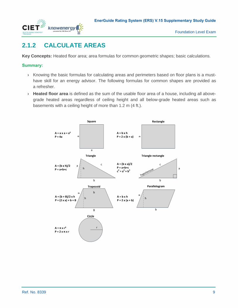
2.1.2 CALCULATE AREAS
Key Concepts: Heated floor area; area formulas for common geometric shapes; basic calculations.
Summary:
› Knowing the basic formulas for calculating areas and perimeters based on floor plans is a must-
have skill for an energy advisor. The following formulas for common shapes are provided as
a refresher.
› Heated floor area is defined as the sum of the usable floor area of a house, including all above-
grade heated areas regardless of ceiling height and all below-grade heated areas such as
basements with a ceiling height of more than 1.2 m (4 ft.).
Square Rectangle
Triangle
ParallelogramTrapezoid
Circle
a
a
b
h
b
B b
h
a
A = a x a = a²P = 4a
A = (b x h)/2P = a+b+c
A = (b + B)/2 x hP = (2 x a) + b + B
h
A = b x hP = 2 x (b + a)
A = b x hP = 2 x (a + b)
A = π x r²P = 2 x π x r
r
a c
a
a
Triangle rectangle
b
A = (b x a)/2P = a+b+cc2 = a2 + b2
a
c
EnerGuide Rating System (ERS) V.15 Supplementary Study Guide
Foundation Level Exam
Ref. No. 8339 10
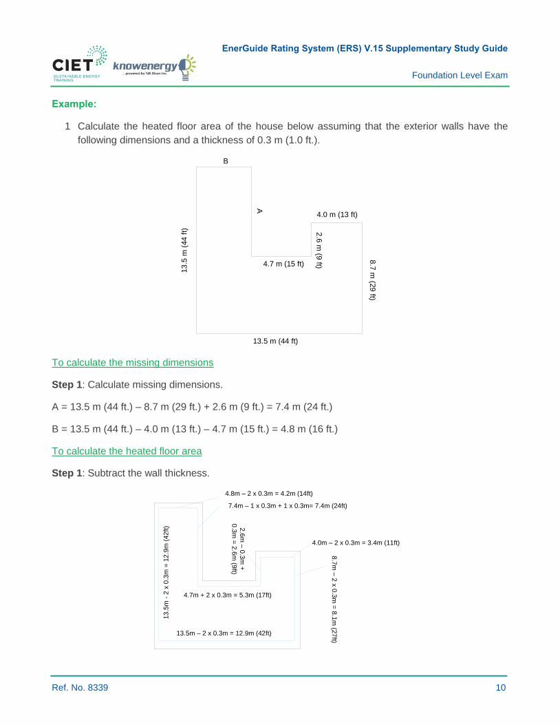
Example:
1 Calculate the heated floor area of the house below assuming that the exterior walls have the
following dimensions and a thickness of 0.3 m (1.0 ft.).
13
.5 m
(44
ft)
13.5 m (44 ft)
8.7
m (2
9 ft)
4.0 m (13 ft)
2.6
m (9
ft)4.7 m (15 ft)
A
B
To calculate the missing dimensions
Step 1: Calculate missing dimensions.
A = 13.5 m (44 ft.) – 8.7 m (29 ft.) + 2.6 m (9 ft.) = 7.4 m (24 ft.)
B = 13.5 m (44 ft.) – 4.0 m (13 ft.) – 4.7 m (15 ft.) = 4.8 m (16 ft.)
To calculate the heated floor area
Step 1: Subtract the wall thickness.
2.6
m –
0.3
m +
0.3
m =
2.6
m (9
ft)
4.7m + 2 x 0.3m = 5.3m (17ft)
13.5m – 2 x 0.3m = 12.9m (42ft)
13
.5m
- 2
x 0
.3m
= 1
2.9
m (
42
ft)
4.8m – 2 x 0.3m = 4.2m (14ft)
7.4m – 1 x 0.3m + 1 x 0.3m= 7.4m (24ft)
4.0m – 2 x 0.3m = 3.4m (11ft)
8.7
m –
2 x
0.3
m =
8.1
m (2
7ft)
EnerGuide Rating System (ERS) V.15 Supplementary Study Guide
Foundation Level Exam
Ref. No. 8339 11
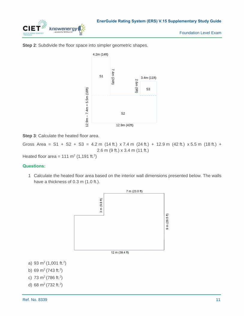
Step 2: Subdivide the floor space into simpler geometric shapes.
12.9m (42ft)12
.9m
– 7
.4m
= 5
.5m
(18
ft)
4.2m (14ft)
7.4
m (2
4ft)
3.4m (11ft)2.6
m (9
ft)
S1
S2
S3
Step 3: Calculate the heated floor area.
Gross Area = S1 + S2 + S3 = 4.2 m (14 ft.) x 7.4 m (24 ft.) + 12.9 m (42 ft.) x 5.5 m (18 ft.) +
2.6 m (9 ft.) x 3.4 m (11 ft.)
Heated floor area = 111 m2 (1,191 ft.2)
Questions:
1 Calculate the heated floor area based on the interior wall dimensions presented below. The walls
have a thickness of 0.3 m (1.0 ft.).
a) 93 m2 (1,001 ft.2)
b) 69 m2 (743 ft.2)
c) 73 m2 (786 ft.2)
d) 68 m2 (732 ft.2)
EnerGuide Rating System (ERS) V.15 Supplementary Study Guide
Foundation Level Exam
Ref. No. 8339 12
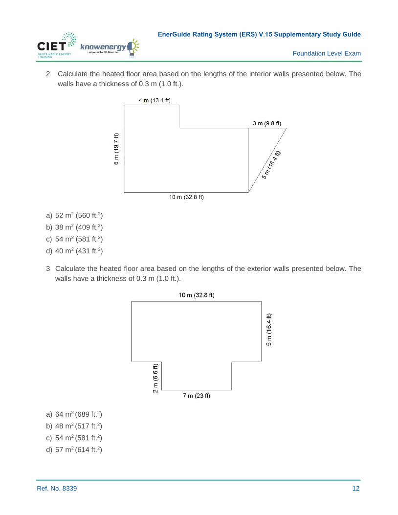
2 Calculate the heated floor area based on the lengths of the interior walls presented below. The
walls have a thickness of 0.3 m (1.0 ft.).
a) 52 m2 (560 ft.2)
b) 38 m2 (409 ft.2)
c) 54 m2 (581 ft.2)
d) 40 m2 (431 ft.2)
3 Calculate the heated floor area based on the lengths of the exterior walls presented below. The
walls have a thickness of 0.3 m (1.0 ft.).
a) 64 m2 (689 ft.2)
b) 48 m2 (517 ft.2)
c) 54 m2 (581 ft.2)
d) 57 m2 (614 ft.2)

EnerGuide Rating System (ERS) V.15 Supplementary Study Guide
Foundation Level Exam
Ref. No. 8339 13
Suggested Reading:
None.
Solutions:
1. a) 93 m2 (1,001 ft.2)
2. c) 54 m2 (581 ft.2)
3. c) 54 m2 (581 ft.2): Notice that the drawing represents the dimensions of the exterior walls,
unlike the other questions for which the interior walls are presented.
EnerGuide Rating System (ERS) V.15 Supplementary Study Guide
Foundation Level Exam
Ref. No. 8339 14
2.1.6 CALCULATE ANGLES AND SLOPES
Key Concepts: roof slope; roof span; roof rise; roof slope expressed in degrees and ratios.
Summary:
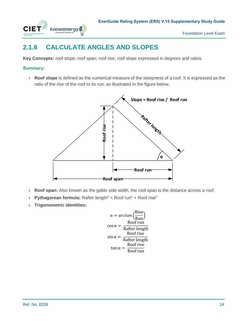
› Roof slope is defined as the numerical measure of the steepness of a roof. It is expressed as the
ratio of the rise of the roof to its run, as illustrated in the figure below.
α
α
Slope = Roof rise / Roof run
Roof span
Roof run
Ro
of r
ise
› Roof span: Also known as the gable side width, the roof span is the distance across a roof.
› Pythagorean formula: Rafter length2 = Roof run2 + Roof rise2
› Trigonometric identities:
α = 𝑎𝑟𝑐𝑡𝑎𝑛 (Rise
Run)
cos α = Roof run
Rafter length
sin α = Roof rise
Rafter length
tan α = Roof rise
Roof run

EnerGuide Rating System (ERS) V.15 Supplementary Study Guide
Foundation Level Exam
Ref. No. 8339 15
Example:
A roof has a slope of 4/12. What is its slope in degrees (°) and in (%)?
To calculate the slope of 4/12 in degrees, use this formula:
α = arctan (Rise
Run) = arctan (
4
12) = 18.4°
The calculation of the slope of 4/12 in (%) is easier:
4
12× 100 = 33.3%
Questions:
1. A roof has a run of 6 feet and a rise of 3 feet. What is its slope?
a) 6/3
b) 1/2
c) 3/12
d) 12/3
2. A roof has a rise of 10 feet and a span of 20 feet. What is its slope?
a) 1/2
b) 20/10
c) 1/1
d) 5/20
3. A roof has a rafter with a length of 25 feet and a rise of 15 feet. What is its slope?
a) 3/4
b) 5/4
c) 4/5
d) 4/3
Suggested Reading:
› Canada Mortgage and Housing Corporation. (2014). Ceiling and roof framing, Canadian Wood-
Frame House Construction (Chapter 11). Retrieved from https://www.cmhc-
schl.gc.ca/odpub/pdf/61010.pdf
EnerGuide Rating System (ERS) V.15 Supplementary Study Guide
Foundation Level Exam
Ref. No. 8339 16
Solutions:
1. b) 1/2
2. c) 1/1
3. a) 3/4

EnerGuide Rating System (ERS) V.15 Supplementary Study Guide
Foundation Level Exam
Ref. No. 8339 17
2.2.2 CONVERT MEASUREMENTS FROM IMPERIAL UNITS TO METRIC UNITS
Key Concepts: Conversion of length, area, volume, temperature, mass and R-value.
Conversion Table:
The following table provides typical conversion factors used by energy advisors.
Imperial Metric
Length
1 inch 2.54 cm
1 foot 0.3048 m
Area
1 in² 6.45 cm²
1 ft.² 0.0929 m²
Volume
1 ft.³ 0.0283 m³
1 US gallon 3.7854 liters
Temperature
°C = (°F -32) x 5/9
Mass
1 lb 0.4536 kg
1 US ton 0.9072 t
R-value
1 R = 0.1761 RSI
Energy
1 BTU 1,055 J
Power
1 BTU/h 0.293 W
Example:
What is the maximum flow rate in m3/h and l/sec of a water heater that has a maximum flow rate of
40 GPM?
40gallons
min×
3.7854 liters
1 gallon×
1 m3
1000 liters×
60 min
1 h= 𝟗. 𝟎𝟖
𝐦𝟑
𝐡
40gallons
min×
3.7854 liters
1 gallon×
1 min
60 sec= 𝟐. 𝟓𝟐
𝐥
𝐬𝐞𝐜
EnerGuide Rating System (ERS) V.15 Supplementary Study Guide
Foundation Level Exam
Ref. No. 8339 18
Question:
1 What is the heating capacity in kW of an 80,000 BTU/h furnace?
a) 23.44 kW
b) BTU/h is an energy unit and cannot be converted to kW
c) 23,440 kW
d) 273.04 kW
Suggested Reading:
› Canadian Home Builders' Association. (2006). Conversion factors, Builders’ Manual (6th Edition)
(Appendix 6).
Solution:
1. a)
EnerGuide Rating System (ERS) V.15 Supplementary Study Guide
Foundation Level Exam
Ref. No. 8339 19
3.2.3 DISTINGUISH BETWEEN NOMINAL AND EFFECTIVE THERMAL RESISTANCE
Key Concepts: Thermal resistance; RSI value; R-value; nominal thermal resistance; effective
thermal resistance.
Thermal Resistance:
› Thermal resistance is the resistance to heat flow.
› Thermal resistance is indicated by an RSI value (metric) and an R-value (imperial).
› The higher the resistance value, the slower the rate of heat transfer through the material.
Nominal Thermal Resistance:
› The nominal thermal resistance value is the insulating value for the material itself.
› In other words, it is the insulation value of the material.
- E.g. RSI 3.52 batt.
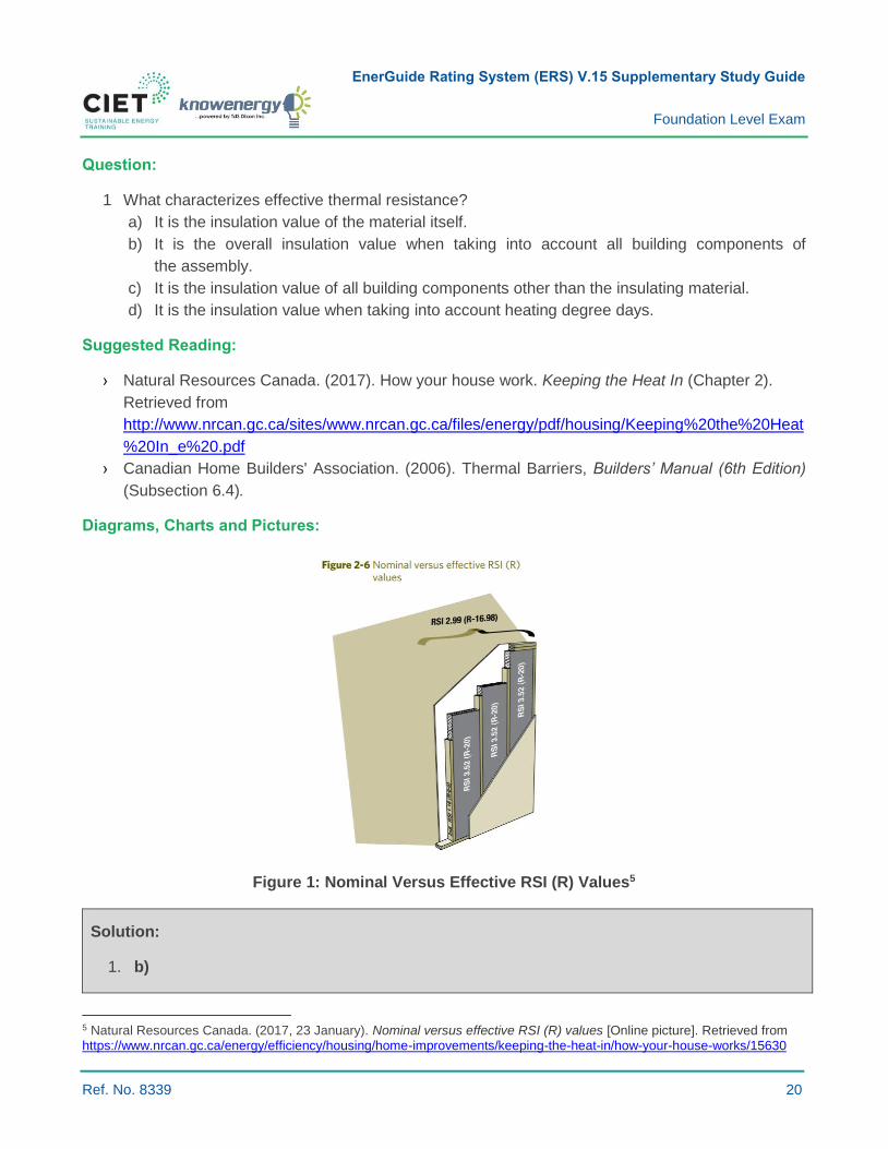
Effective Thermal Resistance:
› The effective thermal resistance value accounts for all building components in the assembly.
› The effective thermal resistance value also takes into account thermal bridging. A thermal bridge
is any solid material that connects the warm side of the envelope to the cold side.
Tip: When insulation materials such as foam boards are installed on one side of the thermal bridge, it
acts like a roadblock by reducing heat flow.
Example:
› The wall studs and top and bottom plates reduce the effective insulation value of insulated walls,
whereas sheathing, drywall and the exterior finish increase wall thermal resistance.
Table 2 : Conversion of an R-value to RSI
Conversion of an R-value to RSI Conversion of an RSI to R-value
RSI = R-value / 5.678 R-value = RSI x 5.678
EnerGuide Rating System (ERS) V.15 Supplementary Study Guide
Foundation Level Exam
Ref. No. 8339 20
Question:
1 What characterizes effective thermal resistance?
a) It is the insulation value of the material itself.
b) It is the overall insulation value when taking into account all building components of
the assembly.
c) It is the insulation value of all building components other than the insulating material.
d) It is the insulation value when taking into account heating degree days.
Suggested Reading:
› Natural Resources Canada. (2017). How your house work. Keeping the Heat In (Chapter 2).
Retrieved from
http://www.nrcan.gc.ca/sites/www.nrcan.gc.ca/files/energy/pdf/housing/Keeping%20the%20Heat
%20In_e%20.pdf
› Canadian Home Builders' Association. (2006). Thermal Barriers, Builders’ Manual (6th Edition)
(Subsection 6.4).
Diagrams, Charts and Pictures:
Figure 1: Nominal Versus Effective RSI (R) Values5
Solution:
1. b)
5 Natural Resources Canada. (2017, 23 January). Nominal versus effective RSI (R) values [Online picture]. Retrieved from https://www.nrcan.gc.ca/energy/efficiency/housing/home-improvements/keeping-the-heat-in/how-your-house-works/15630
EnerGuide Rating System (ERS) V.15 Supplementary Study Guide
Foundation Level Exam
Ref. No. 8339 21
3.2.7 DESCRIBE TECHNIQUES TO ENSURE THE CONTINUITY OF THE AIR BARRIER AROUND SERVICE PENETRATIONS (PLUMBING, ELECTRICAL, MECHANICAL) THROUGHOUT THE BUILDING
Key Concepts: Air barrier; service penetration; sealant.
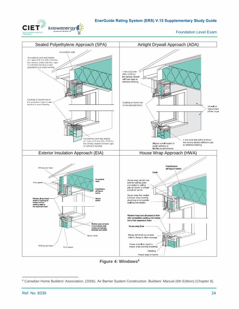
Summary:
› The air barrier must be continuous and can be located anywhere within the building envelope.
› It is necessary to ensure air barrier continuity around the service penetrations (plumbing, electrical
and mechanical penetrations).
› The appropriate technique to be used to ensure air barrier continuity around service penetrations
depends on the air barrier type.
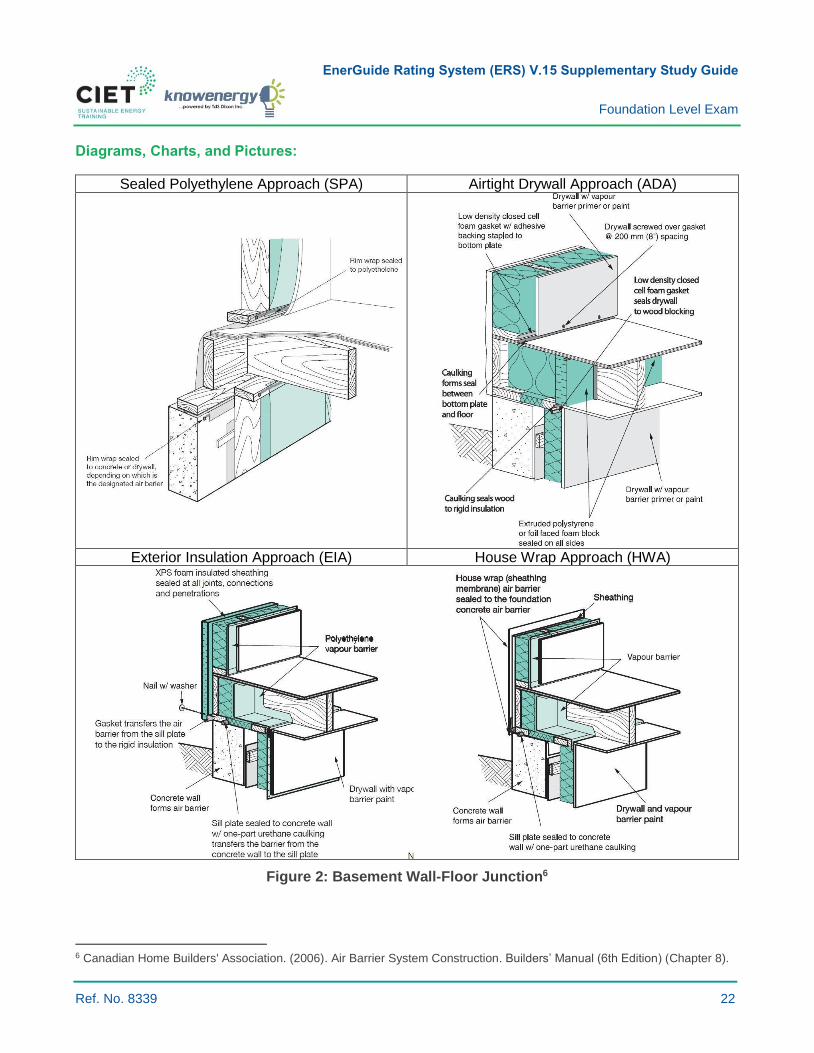
› The logic behind air barrier continuity is illustrated in the figures below. The logic can be
extrapolated to most service penetrations. Candidates are encouraged to compare the figures in
detail to better understand how continuity is ensured with each approach.
Question:
1 Which of the following statements is true about the house wrap air barrier approach?
a) It is sealed around service penetrations using caulking, tape or a gasket.
b) It covers the outside wall of the foundations.
c) Plastic air-tight electrical boxes can be used to ensure continuity around in-house
electrical boxes.
d) The house wrap is sealed directly to the window frame using expanding foam.
Suggested Reading:
› Canadian Home Builders' Association. (2006). Air Barrier System Construction, Builders’ Manual
(6th Edition) (Chapter 8).
EnerGuide Rating System (ERS) V.15 Supplementary Study Guide
Foundation Level Exam
Ref. No. 8339 22
Diagrams, Charts, and Pictures:
Sealed Polyethylene Approach (SPA) Airtight Drywall Approach (ADA)
Exterior Insulation Approach (EIA) House Wrap Approach (HWA)
Figure 2: Basement Wall-Floor Junction6
6 Canadian Home Builders' Association. (2006). Air Barrier System Construction. Builders’ Manual (6th Edition) (Chapter 8).

EnerGuide Rating System (ERS) V.15 Supplementary Study Guide
Foundation Level Exam
Ref. No. 8339 23
Sealed Polyethylene Approach (SPA)
Airtight Drywall Approach (ADA)
Exterior Insulation Approach (EIA) House Wrap Approach (HWA)
Figure 3: The Electrical Box7
7 Canadian Home Builders' Association. (2006). Air Barrier System Construction. Builders’ Manual (6th Edition) (Chapter 8).
EnerGuide Rating System (ERS) V.15 Supplementary Study Guide
Foundation Level Exam
Ref. No. 8339 24
Sealed Polyethylene Approach (SPA) Airtight Drywall Approach (ADA)
Exterior Insulation Approach (EIA) House Wrap Approach (HWA)
Figure 4: Windows8
8 Canadian Home Builders' Association. (2006). Air Barrier System Construction. Builders’ Manual (6th Edition) (Chapter 8).
EnerGuide Rating System (ERS) V.15 Supplementary Study Guide
Foundation Level Exam
Ref. No. 8339 25
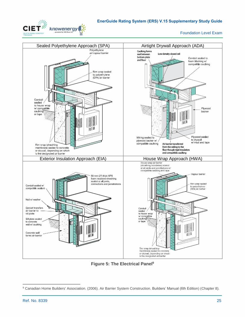
Sealed Polyethylene Approach (SPA) Airtight Drywall Approach (ADA)
Exterior Insulation Approach (EIA) House Wrap Approach (HWA)
Figure 5: The Electrical Panel9
9 Canadian Home Builders' Association. (2006). Air Barrier System Construction. Builders’ Manual (6th Edition) (Chapter 8).

EnerGuide Rating System (ERS) V.15 Supplementary Study Guide
Foundation Level Exam
Ref. No. 8339 26
Sealed Polyethylene Approach (SPA) Airtight Drywall Approach (ADA)
Exterior Insulation Approach (EIA) House Wrap Approach (HWA)
Figure 6: Plumbing Penetration10
10 Canadian Home Builders' Association. (2006). Air Barrier System Construction. Builders’ Manual (6th Edition) (Chapter 8).
EnerGuide Rating System (ERS) V.15 Supplementary Study Guide
Foundation Level Exam
Ref. No. 8339 27
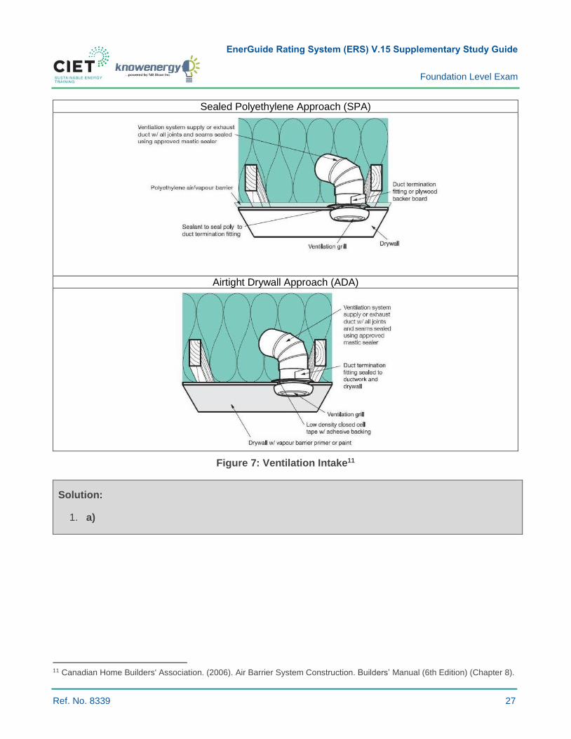
Sealed Polyethylene Approach (SPA)
Airtight Drywall Approach (ADA)
Figure 7: Ventilation Intake11
Solution:
1. a)
11 Canadian Home Builders' Association. (2006). Air Barrier System Construction. Builders’ Manual (6th Edition) (Chapter 8).
EnerGuide Rating System (ERS) V.15 Supplementary Study Guide
Foundation Level Exam
Ref. No. 8339 28
3.2.9 DESCRIBE FOUNDATION DRAINAGE SYSTEMS
Key Concepts: Water penetration; foundation drainage.
Summary:
› Effective foundation drainage systems help prevent water leaking through foundations from
the exterior.
› Water infiltration can cause major problems.
How Water Enters a Basement:
1 Water can enter basements and crawlspaces in several ways:
- Water is released from concrete walls and slabs for up to a year after they have been installed,
thereby increasing indoor humidity levels.
- Water diffuses inward through improperly damp-proofed walls and slabs.
- Moisture moves up or through the foundation walls via capillary action.
- Water vapour is carried by infiltrating humid air in summer, which condenses on
cooler surfaces.
- Solar vapour drive pushes moisture through the top of the foundation wall, which can also lead
to condensation issues.
- Bulk water penetration whereby water leaks through cracks in the foundation due to
improper drainage.
How to Deal with Water that Comes into Contact with a Foundation Wall:
1 As much as possible, water should be kept away from foundation walls.
2 There are two strategies for addressing surface and groundwater that comes into contact with
foundation walls:
- Continuous and effective wall drainage interconnected to a compatible drainage system to
prevent accumulation of water against the outer surfaces of the envelope (walls and floor slabs)
– exterior drainage and damp proofing.
- Full and continuous barrier to water penetration – waterproofing.
EnerGuide Rating System (ERS) V.15 Supplementary Study Guide
Foundation Level Exam
Ref. No. 8339 29
Effective Wall Drainage:
› Proper water management includes:
- Direct water away from the foundation through surface drainage: properly sized and located
gutters and downspout systems. Do not terminate downspouts without directing them away
from foundation walls.
- Ensure proper grading that slopes away from foundation walls, if possible two to three percent.
- Ensure free-drainage backfill or a drainage plane next to the foundation.
- Use a properly graded perforated drainage pipe system protected by geotextile cloth which
prevent drainage pipe system from clogging by fine soil particulates.
- Ensure an effective means of conveying water away from the foundation system to the
municipal storm sewer or to open space is in place.
Question:
1 Which of the following is not included in an effective wall drainage system:
a) Surface drainage to direct water away from the foundation.
b) Free-drainage backfill or a drainage plane next to the foundation.
c) Graded drainage pipe system.
d) A permeable top layer that channels water to the drainage pipe system.
Suggested Reading:
Canadian Home Builders' Association. (2006). Water management, Builders’ Manual (6th Edition)
(Subsection 9.1.1).

EnerGuide Rating System (ERS) V.15 Supplementary Study Guide
Foundation Level Exam
Ref. No. 8339 30
Diagrams, Charts, Pictures:
Figure 8: Water Management12
Solution:
1. d)
12 Canadian Home Builders' Association. (2006). Water management, Builders’ Manual (6th Edition) (Subsection 9.1.1).
EnerGuide Rating System (ERS) V.15 Supplementary Study Guide
Foundation Level Exam
Ref. No. 8339 31
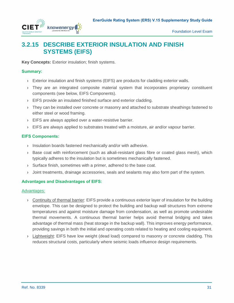
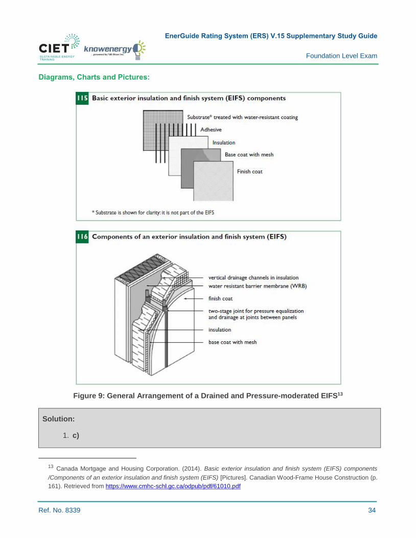
3.2.15 DESCRIBE EXTERIOR INSULATION AND FINISH SYSTEMS (EIFS)
Key Concepts: Exterior insulation; finish systems.
Summary:
› Exterior insulation and finish systems (EIFS) are products for cladding exterior walls.
› They are an integrated composite material system that incorporates proprietary constituent
components (see below, EIFS Components).
› EIFS provide an insulated finished surface and exterior cladding.
› They can be installed over concrete or masonry and attached to substrate sheathings fastened to
either steel or wood framing.
› EIFS are always applied over a water-resistive barrier.
› EIFS are always applied to substrates treated with a moisture, air and/or vapour barrier.
EIFS Components:
› Insulation boards fastened mechanically and/or with adhesive.
› Base coat with reinforcement (such as alkali-resistant glass fibre or coated glass mesh), which
typically adheres to the insulation but is sometimes mechanically fastened.
› Surface finish, sometimes with a primer, adhered to the base coat.
› Joint treatments, drainage accessories, seals and sealants may also form part of the system.
Advantages and Disadvantages of EIFS:
Advantages:
› Continuity of thermal barrier: EIFS provide a continuous exterior layer of insulation for the building
envelope. This can be designed to protect the building and backup wall structures from extreme
temperatures and against moisture damage from condensation, as well as promote undesirable
thermal movements. A continuous thermal barrier helps avoid thermal bridging and takes
advantage of thermal mass (heat storage in the backup wall). This improves energy performance,
providing savings in both the initial and operating costs related to heating and cooling equipment.
› Lightweight: EIFS have low weight (dead load) compared to masonry or concrete cladding. This
reduces structural costs, particularly where seismic loads influence design requirements.
EnerGuide Rating System (ERS) V.15 Supplementary Study Guide
Foundation Level Exam
Ref. No. 8339 32
› Water penetration resistance: Properly applied and maintained EIFS provide good resistance to
rain water penetration. The risk of rainwater penetration tends to be limited to joints, interfaces
with other materials, and where lamina is damaged or otherwise defective. Most EIFS have a
rained version of the system, which should be used whenever EIFS are likely to be wetted.
› Flexibility: Compared to rigid cladding systems, many EIFS are relatively flexible and able to better
accommodate substrate flexure or other movements without cracking.
› Appearance: A wide range of finish colours and textures are available. Complex surface features
are easily incorporated for distinct and interesting architectural facades.
› Reparability: Localized damage or defects in EIFS can be easily repaired. Appearance is usually
restored or renewed by reapplying the finish or painting.
› Retrofit applications: Lightweight EIFS are often applied directly over existing cladding systems to:
- Improve appearance;
- Increase thermal performance;
- Correct problems caused by rain penetration;
- Improve resistance to condensation or entrapped moisture;
- Protect the structure and existing cladding from deterioration.
Disadvantages:
› Combustibility: Some EIFS incorporate combustible components and/or combustible foam plastic
insulation that must be protected in accordance with the applicable building code.
› Impact resistance: EIFS are vulnerable to impact damage as a result of thin lamina. In areas where
impact damage is likely, an appropriately reinforced EIFS product must be used.
› Compatibility: Each EIFS constituent component and material connected to the EIFS must be
compatible to assure acceptable performance. This includes the lamina, sealants, joint treatments,
insulation, adhesive/fastening, moisture/air/vapour barriers and substrate. The manufacturer
should be consulted to verify that each component or material has been tested for compatibility.
› Staining: If exposed to frequent wetting, staining from mildew growth can result. Frequent wetting
occurs where the EIFS are not effectively protected from rain or in high-humidity climates where
areas are not exposed to direct sunlight (north elevations, shaded areas, etc.).
› Sensitivity to workmanship: As with many multi-component hand-applied systems, EIFS
performance is sensitive to workmanship. Quality control is necessary to ensure that components
are properly applied and they effectively work together to provide the desired performance.
› Long-term performance: While a minimum 30-year service life for properly designed and applied
EIFS is anticipated and indicated by field performance, longer-term service for many product
formulations has not been determined. As with all cladding, maintenance is a prerequisite to
longevity. Problems with local deterioration or moisture ingress must be dealt with promptly to
achieve an acceptable service life.
EnerGuide Rating System (ERS) V.15 Supplementary Study Guide
Foundation Level Exam
Ref. No. 8339 33
Question:
1 Which of the following statements is true about an EIFS?
a) It is a preassembled exterior insulation finish system composed of sheathing, insulation, base
coat, and finish coat.
b) It acts as an air barrier.
c) It reduces thermal bridging through framing.
d) EIFS are standardized systems that can all be installed the same way.
Suggested Readings:
› Canadian Home Builders' Association. (2006). Exterior Insulating Finish Systems, Builders’
Manual (6th Edition) (Subsection 11.12).
› Canada Mortgage and Housing Corporation. (2014). Ceiling and roof framing. Canadian Wood-
Frame House Construction (Chapter 11). Retrieved from https://www.cmhc-
schl.gc.ca/odpub/pdf/61010.pdf
EnerGuide Rating System (ERS) V.15 Supplementary Study Guide
Foundation Level Exam
Ref. No. 8339 34
Diagrams, Charts and Pictures:
Figure 9: General Arrangement of a Drained and Pressure-moderated EIFS13
Solution:
1. c)
13 Canada Mortgage and Housing Corporation. (2014). Basic exterior insulation and finish system (EIFS) components
/Components of an exterior insulation and finish system (EIFS) [Pictures]. Canadian Wood-Frame House Construction (p.
161). Retrieved from https://www.cmhc-schl.gc.ca/odpub/pdf/61010.pdf
EnerGuide Rating System (ERS) V.15 Supplementary Study Guide
Foundation Level Exam
Ref. No. 8339 35
3.3.2 DESCRIBE THE ADVANTAGES AND DISADVANTAGES OF ADDING INSULATION TO THE EXTERIOR VERSUS THE INTERIOR OF THE BUILDING ENVELOPE
Key Concepts: Interior insulation; exterior insulation; above and below grade applications; renovation.
Proper insulation installation is a major key to thermal comfort in houses during hot and cold seasons.
However, there are several techniques to apply insulation on house envelopes depending on where it
is applied.
Above Grade
Interior Insulation
Remove existing finish wall surface, reinsulate, apply proper vapour barrier if required, seal around all
windows/doors and exterior wall penetrations, re-apply finish wall surface.
Advantages:
› End result: properly insulated and sealed wall system.
› Can lead to the identification of other hidden problems that require attention.
Disadvantages:
› Time intensive and invasive. Homeowners must be prepared to live in a construction zone or move
out during the renovation period.
› Can lead to unexpected increased costs due to identification of hidden problems that
require attention.
› Reducing air leakage from the interior can increase dependency on mechanical ventilation
systems. In homes where these are not present, they sometimes need to be installed
after insulating.
› Might reduce interior livable area.
Typical Applications:
Fibreglass batt, rock-mineral wool, open cell spray foam, closed cell spray foam, wetted cellulose, blown
cellulose/fibreglass.
EnerGuide Rating System (ERS) V.15 Supplementary Study Guide
Foundation Level Exam
Ref. No. 8339 36
Exterior Insulation
It is always best to remove existing siding and perform any upgrades to the structure, wiring, plumbing,
cavity insulation, as well as vapour and air barriers before installing additional insulation under new
siding. However, rigid board, batt or blanket insulation can be applied on top of old siding.
Advantages:
› Additional layers of insulation can be added since space is usually not a limiting factor to this type
of upgrade (unless zero lot line).
› Eliminates thermal bridging in some areas.
› Drill and fill blown cellulose is a cost-effective method of densely packing insulation in exterior wall
cavities with minimal intrusion on interior spaces.
› Minimal disruption to occupants.
› Air sealing is more effectively achieved from the exterior.
Disadvantages:
› Contractors are required to build out window and door flashing systems when applying exterior
rigid packages.
› Moisture damage can remain hidden and unknown to the homeowner.
› Drill and fill blown cellulose can settle over time within the wall cavity, thus leading to the
compression of existing insulation (if present).
Typical Applications:
EIFS, rigid insulation, drill and fill blown cellulose/fibreglass.
Below Grade
Insulating from the outside is best, but it is often necessary to insulate from the inside for economical
and practical reasons. Sometimes a combination of approaches is required.
Interior Insulation
This may involve installing rigid insulation board and drywall, a wood-frame wall and insulation or other
insulation combinations. The choice of method depends on a number of factors including moisture
issues, the need to account for moisture and air/vapour barriers, how the space is to be used, and cost.
EnerGuide Rating System (ERS) V.15 Supplementary Study Guide
Foundation Level Exam
Ref. No. 8339 37
Advantages:
› It can be incorporated into a plan to finish a basement.
› The work can be carried out at any time of the year and one section at a time.
› It is often easier and cheaper to insulate the full wall and thus achieve high insulating values.
› Connecting with above slab insulation is possible for a thermal bridge-free connection.
› Landscaping and driveways are not disturbed.
Disadvantages:
› New walls are at risk of rotting if a basement has moisture problems.
› Adding insulation from the interior makes the foundation walls colder. Any humid air that comes
in contact with these cold walls will condense. Interior finishes hide or obscure moisture problems
as they develop.
› Obstructions such as electrical panels, wiring, plumbing, stairs, and partition walls make the work
more difficult and insulation less effective.
› Reducing air leakage from the interior sometimes increases dependency on mechanical
ventilation systems. In homes where these are not present, they are sometimes required
after insulating.
› It sometimes results in decreased interior floor area.
Exterior Insulation
This involves excavating around the foundation, waterproofing and installing insulation. Flashing must
be attached to keep water from infiltrating behind the insulation and installing a protection against
ultraviolet light on exposed insulation sections.
Advantages:
› The outside wall is usually more continuous and easier to insulate.
› You can effectively see and correct any moisture or structural problems. Rubble or brick
foundations and foundations with water leakage, dampness or other moisture problems should be
insulated from the outside. Repairing the foundation, parging, waterproofing and installing a
drainage system can be simultaneously accomplished.
› No disruption in the house, no interior work disturbed, and no inside space is lost.
› Freeze-thaw stresses are eliminated, and frost is unlikely to penetrate down to the footings.
› The mass of the foundation is within the insulated portion of the house and will tend to even out
temperature fluctuations.
EnerGuide Rating System (ERS) V.15 Supplementary Study Guide
Foundation Level Exam
Ref. No. 8339 38
Disadvantages:
› Digging a trench around a house by hand can be difficult and risky depending on soil type and
depth. It is much easier to use machinery, but access can be a problem.
› Storing the dirt can be a problem.
› Excavation cannot be carried out in winter and can be a problem in the spring or throughout the
year if the property is located on a high water table.
› Features such a non-removable steps, paved carports, shrubbery, trees or fences can make the
work difficult.
› Rubble or brick foundations might be partially supported by the soil. Get expert advice before
commencing works.
› It is expensive to obtain high insulation levels, and the retrofit might negatively impact the
appearance of the house.
› Depending on the above grade wall insulation strategy, there can be a thermal bridge at
the junction.
› Connecting with any slab insulation in the house is impossible. To achieve a thermal bridge-free
connection, a combination of exterior and interior insulation is required.
Question:
1 What is an advantage of adding below grade wall insulation to the exterior of a building envelope?
a) No disruption in the house, no interior work disturbed, but inside space is lost.
b) Freeze-thaw stresses are eliminated, and frost is unlikely to penetrate down to the footings.
c) The mass of the foundation is within the insulated portion of the house and will tend to even
out temperature fluctuations.
d) Can lead to the identification of other hidden problems that require attention.
Suggested Readings:
› Natural Resources Canada. (2017). Basement insulation, Keeping the Heat In (Chapter 6).
Retrieved from
http://www.nrcan.gc.ca/sites/www.nrcan.gc.ca/files/energy/pdf/housing/Keeping%20the%20Heat
%20In_e%20.pdf
› Natural Resources Canada. (2017). Insulating walls. Keeping the Heat In (Chapter 7). Retrieved
from http://www.nrcan.gc.ca/sites/www.nrcan.gc.ca/files/energy/pdf/housing/Keeping%20the%2
0Heat%20In_e%20.pdf
› Canada Mortgage and Housing Corporation. (2014). Canadian Wood-Frame House Construction.
Retrieved from https://www.cmhc-schl.gc.ca/odpub/pdf/61010.pdf

EnerGuide Rating System (ERS) V.15 Supplementary Study Guide
Foundation Level Exam
Ref. No. 8339 39
Diagrams, Charts, Pictures:
Figure 10: Exterior Basement Insulation14
14 Natural Resources Canada. (2016, 2 December). Components of exterior insulation [Online picture]. Retrieved from https://www.nrcan.gc.ca/energy/efficiency/housing/home-improvements/keeping-the-heat-in/basement-insulation/15639
EnerGuide Rating System (ERS) V.15 Supplementary Study Guide
Foundation Level Exam
Ref. No. 8339 40
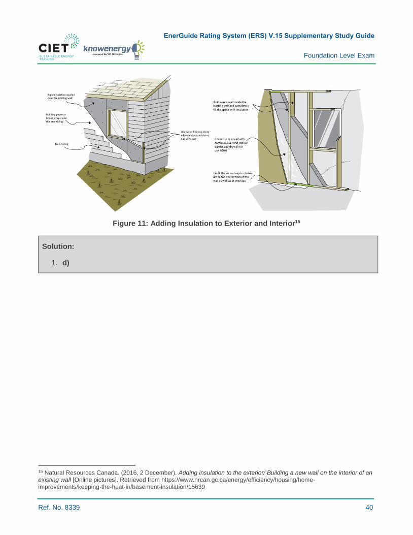
Figure 11: Adding Insulation to Exterior and Interior15
Solution:
1. d)
15 Natural Resources Canada. (2016, 2 December). Adding insulation to the exterior/ Building a new wall on the interior of an existing wall [Online pictures]. Retrieved from https://www.nrcan.gc.ca/energy/efficiency/housing/home-improvements/keeping-the-heat-in/basement-insulation/15639
EnerGuide Rating System (ERS) V.15 Supplementary Study Guide
Foundation Level Exam
Ref. No. 8339 41
3.4.3 DESCRIBE HIGHLY EFFICIENT MECHANICAL SYSTEMS, INCLUDING HOW THEY CAN BE INTEGRATED
Key Concepts: High efficiency systems; in-floor hydronic systems; balanced ventilation; heat recovery
ventilators (HRVs); energy recovery ventilators (ERVs); ground-source heat pumps (GSHPs); air-source
heat pumps (ASHPs); domestic hot water heat pumps; condensing gas-fired equipment; on-demand
domestic hot water systems; high efficiency motors; integrated mechanical systems (IMS); proper sizing
of equipment.
Summary:
› Many highly efficient mechanical system options are available for houses.
› The mechanical systems in a home can include heating, cooling, and ventilation equipment, as
well as other devices. Their primary role is to provide a healthy and comfortable
indoor environment.
› Energy-efficient equipment upgrades have higher initial costs that can be offset by lower operating
costs, increased value, lower GHG emissions, as well as improved comfort and health factors.
› It is always important to consider the full range of opportunities and consider interactive effects
when selecting or upgrading mechanical systems in houses.
› For further information on efficiency rating definitions, see Learning Objective 6.1.6.
Radiant Heating Systems:
› In-floor or underfloor hydronic heating systems use a network of tubing embedded in the floor,
which then heats the inside of the room via conduction, radiation and convection. Hydronic
systems use water or a mix of water and anti-freeze such as propylene glycol.
› Electric radiant floors typically consist of electric cables built into the floor. Systems that feature
mats made of electrically conductive plastic mounted to the subfloor below a floor covering such
as tile are also available.
› Integration:
- Hydronic radiant systems can be used with GSHPs, ASHPs, IMS, or boilers. They are also
compatible with solar water heating equipment.
Balanced Ventilation and Heat Recovery Ventilators (HRVs/ERVs):
- See Subsections 6.4.2 and 6.4.6 herein.
EnerGuide Rating System (ERS) V.15 Supplementary Study Guide
Foundation Level Exam
Ref. No. 8339 42
Ground-Source Heat Pumps (GSHPs):
› GSHPs use the earth, ground water or both as heat sources in the winter and as the heat sink in
the summer.
› Heat is removed from the earth by using a liquid such as water, refrigerant, or an antifreeze
solution; the liquid temperature is raised by the heat pump and the heat is then transferred to
indoor air. During summer months, the process is reversed: heat is taken from indoor air and
transferred to the earth via the liquid.
› Earth-energy systems intended for ground-water or open-system applications have heating
coefficient of performance (COP) ratings ranging from 3.6 to 5.2, and cooling energy efficiency
ratio (EER) ratings between 16.2 and 31.1. Systems intended for closed-loop applications have
heating COP ratings between 3.1 and 4.9, while EER ratings range from 13.4 to 25.8.
› Units range in size from 5 kW to 40 kW (15,000 to 135,000 Btu/h) and include domestic hot water
(DHW) options.
› Geothermal heat pump systems have a service life estimated at 25 years.
› Integration:
- GSHPs are used with forced-air balanced distribution systems or hydronic heating systems;
- They can also be designed and installed to provide heating only, heating with passive cooling,
or heating with active cooling;
- Water from the home water heater is pumped through a coil ahead of the GSHP condenser coil
so that some of the heat that would have been dissipated at the condenser is used to heat
water. Other GSHPs provide DHW on demand; the whole machine switches to providing DHW
when required.
Air-source Heat Pumps (ASHPs):
› ASHPs draw heat from outside air during the heating season and reject heat outside during the
summer cooling season.
› There are two types of ASHPs:
- Air-to-air heat pumps (most common): Extract heat from air and then transfer heat to either the
inside or outside of the house depending on the season;
- Air-to-water heat pumps: Used in homes with hydronic heat distribution systems. During the
heating season, these heat pumps take heat from the outside air and then transfer it to the
water in the hydronic distribution system. If cooling is provided during the summer, the process
is reversed.
› Ductless mini-split heat pumps are ideal for retrofits in houses with hydronic or electric resistance
baseboard heating. Up to eight separate indoor wall-mounted units can be served by one
outdoor section.
EnerGuide Rating System (ERS) V.15 Supplementary Study Guide
Foundation Level Exam
Ref. No. 8339 43
› ASHPs intended for residential applications have seasonal energy efficiency ratio (SEER) ratings
ranging from 13 to 21 and heat seasonal performance factor (HSPF) ratings ranging from 6.3 to
well over 8.6.
› Add-on heat pumps are designed to be used with another source of supplementary heat, such as
an oil, gas or electric furnace.
› The capacity of the heat pump to transfer heat from outside air to the house depends on outdoor
temperatures. As temperatures drop, the ability of the heat pump to absorb heat also drops.
› Using an ASHP near or below 0° C requires a defrost cycle for moisture that condenses and
freezes over the outside coil of the heat pump.
› ASHPs have a service life of between 15 and 20 years.
› Integration:
- ASHPs can be used with forced-air balanced distribution systems or hydronic heating systems
(using an air-to-water heat pump), along with a heat recovery ventilator (HRV) or energy
recovery ventilator (ERV).
- More advanced designs of air-source heat pumps can provide domestic water heating.
- ASHPs are also used in some home ventilation systems to recover heat from outgoing stale air
and transfer it to either incoming fresh air or domestic hot water.
Gas-fired Condensing Equipment:
› Furnaces, boilers, and hot water heaters are equipped with condensing technology with
efficiencies typically equal to or greater than 90 percent annual fuel utilization efficiency (AFUE)
for furnaces and boilers and an Energy Factor (EF) of 0.90 or Thermal Efficiency (TE) of 90% or
higher for hot water heaters.
› Condensing gas-fired equipment can also be used for on-demand domestic water heaters. On-
demand water heating systems have no tank and do not store heated water, thus eliminating water
tank heat loss and increasing efficiency in DHW systems.
› Integration:
- Some condensing gas-fired equipment can be used for both space and DHW heating (combo
or combi systems).
Gas-fired Integrated Mechanical Systems (IMS):
› Integrated mechanical systems (IMS) group the functions of space heating, water heating and
heat recovery ventilation into a single package.
› The advantages of this integration include higher energy efficiency, reduced carbon footprint, as
well as lower installation and maintenance costs.
› Compatible with both forced air and radiant heating distribution approaches.
› Residential gas-fired integrated mechanical systems provide the following:
- Forced air space heating;
- Domestic water heating; and
- Outside air ventilation with heat recovery.

EnerGuide Rating System (ERS) V.15 Supplementary Study Guide
Foundation Level Exam
Ref. No. 8339 44
Controls:
› Programmable thermostats: Most homes in Canada still use simple programmable thermostats to
automatically adjust house temperature. They are equipped with a mechanical or electronic timers
that let users pre-set temperatures for different times of the day and different days of the week.
› Smart or connected thermostats: These units learn the temperature settings that users prefer and
establish a schedule that automatically adjusts to save energy when occupants are asleep or
away. Home energy use data can be tracked and managed. Smart thermostats allow occupants
to control home heating and cooling systems remotely via smartphone, computer or tablet.
› Zone controls: In a forced-air heating system, zone controls involve placing dampers in duct
passages and controlling them with separate thermostats in different areas of the house. Zone
controls are also available for hydronic (hot water) heating systems. The temperature of each zone
is regulated by thermostat-controlled valves on each loop.
Question:
1 Which of the following statements is false regarding high efficiency mechanical systems in houses
and residential buildings?
a) Integrated mechanical systems (IMS) group the functions of space heating, water heating and
heat recovery ventilation into a single package.
b) Geothermal heat pump systems have an estimated working life of 25 years.
c) Air-source heat pumps draw heat from outside air during the heating season and reject
outside heat during the cooling season.
d) Ground-source heat pumps use the earth, ground water or both as heat sources in the
summer and as the heat sink in the winter.
Suggested Readings:
› Canadian Mortgage and Housing Corporation. (2013). High efficiency Air to Air Heat Pump.
Retrieved April 4, 2018, from www.cmhc-schl.gc.ca/en/inpr/su/sufepr/sufepr_001.cfm
› Natural Resources Canada. (2016, 28 October). Integrated mechanical systems. Retrieved from
www.nrcan.gc.ca/energy/efficiency/housing/research/hvac-energy/3941
› Natural Resources Canada. (2018, 12 April). Heat/energy recovery ventilators. Retrieved from
https://www.nrcan.gc.ca/energy/products/categories/cooling-ventilating/ventilating/hrv/16197
› Natural Resources Canada. (2012). Heat Recovery Ventilators. Retrieved from
https://www.nrcan.gc.ca/sites/www.nrcan.gc.ca/files/energy/pdf/energystar/HRV_EN.pdf
› Natural Resources Canada. (2018, 12 April). Air-Source Heat Pumps. Retrieved from
www.nrcan.gc.ca/energy/publications/efficiency/heating-heat-pump/6831
Solution:
1. d)

EnerGuide Rating System (ERS) V.15 Supplementary Study Guide
Foundation Level Exam
Ref. No. 8339 45
4.1.1 DESCRIBE THE LADDER SAFETY PROTOCOL
Key Concepts: Slopes; maximum load; and installation.
Summary
All advisors should be familiar with the safety protocols and equipment.
What Should You Know?
Falls from portable ladders are a major cause of serious injuries. Beware of hazards and take proper
precautions to prevent falling.
Incidents or accidents involving ladders are usually caused by:
› Using the wrong ladder for a specific job.
› Using ladders that are defective or in poor condition.
› Improper care or use, including incorrect positioning, failure to secure the ladder properly, placing
on poor footing, etc.
› Workers lacking adequate training on how to maintain, use or work ladders safely.
About climbing:
› Check for overhead power lines before setting up a ladder.
› Clear debris, tools and other objects from the area around the base and top of the ladder.
› Wear a safety harness and tie the lanyard to a proper anchor (e.g. designed fixed support,
temporary fixed support, an existing structural feature, or a piece of equipment) when working 3 m
(10 ft.) or more off the ground, or when working with both hands. Make sure that you have been
trained on how to use fall-protection devices safely.
› Ensure that only one person is on a single-width ladder. Only one person is allowed on each side
of a double-width ladder.
› Maintain three-point contact at all times.
› Grasp the rungs when climbing a ladder, not the side rails.
› Wear protective footwear with slip-resistant soles and heels.
› Rest frequently to avoid arm fatigue and disorientation when the work requires you to look up and
reach above your head.
› Drape your arms over a rung and rest your head against another rung or side rail if you become
dizzy or panicky. Climb down slowly.
EnerGuide Rating System (ERS) V.15 Supplementary Study Guide
Foundation Level Exam
Ref. No. 8339 46
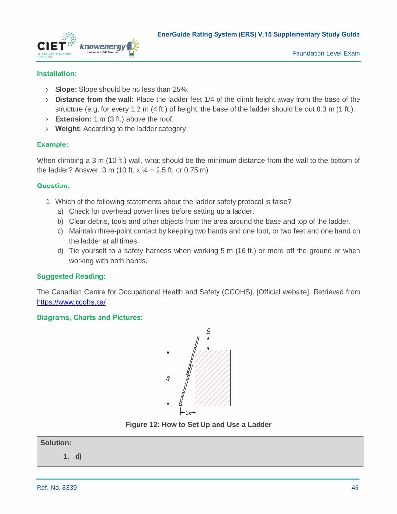
Installation:
› Slope: Slope should be no less than 25%.
› Distance from the wall: Place the ladder feet 1/4 of the climb height away from the base of the
structure (e.g. for every 1.2 m (4 ft.) of height, the base of the ladder should be out 0.3 m (1 ft.).
› Extension: 1 m (3 ft.) above the roof.
› Weight: According to the ladder category.
Example:
When climbing a 3 m (10 ft.) wall, what should be the minimum distance from the wall to the bottom of
the ladder? Answer: 3 m (10 ft. x ¼ = 2.5 ft. or 0.75 m)
Question:
1 Which of the following statements about the ladder safety protocol is false?
a) Check for overhead power lines before setting up a ladder.
b) Clear debris, tools and other objects from the area around the base and top of the ladder.
c) Maintain three-point contact by keeping two hands and one foot, or two feet and one hand on
the ladder at all times.
d) Tie yourself to a safety harness when working 5 m (16 ft.) or more off the ground or when
working with both hands.
Suggested Reading:
The Canadian Centre for Occupational Health and Safety (CCOHS). [Official website]. Retrieved from
https://www.ccohs.ca/
Diagrams, Charts and Pictures:
1x
4x
1m
Figure 12: How to Set Up and Use a Ladder
Solution:
1. d)

EnerGuide Rating System (ERS) V.15 Supplementary Study Guide
Foundation Level Exam
Ref. No. 8339 47
5.1.8 IDENTIFY THE APPROPRIATE LOCATION OF VARIOUS BARRIER SYSTEMS WITHIN THE BUILDING ENVELOPE
Key Concepts: Air barrier; sealant; vapour barrier; tape; permeance.
Air Barrier:
› The air barrier is the leakage control system that prevents air from escaping or entering the
building envelope. It can be located anywhere within the assembly, and it must be continuous. An
appropriate air barrier material must have a tested air leakage result of 0.02 L (s•m2) or less,
measured at an air pressure difference of 75 Pa.
› The air barrier is one of the most important components to control moisture movement, draft and
infiltration of outdoor contaminants. Multiple materials can make up one air barrier system. An
effective air barrier must be continuous and sealed throughout the entire building envelope.
Vapour Barrier:
› The vapour barrier is an important component of the house envelope because it provides
protection from moisture damage to the structure and insulation. The vapour barrier does not need
to be continuous.
› The vapour barrier must: resist the flow of water vapour from the interior, with a water vapour
permeance level less than 60 ng/(Pa∙s∙m2) when measured in accordance with ASTM E96/E96M
Water Vapor Transmission of Materials using the desiccant method (dry cup); be durable; and be
located on the warm side of the insulation. In some cases, it may be part of the insulation or air
barrier (6 mil poly).
Air Barrier Approaches:
› The air barrier system is comprised of: (1) a main air barrier material that forms a principal plane;
and (2) tapes, caulks, foams, gaskets, and other accessories used to make it continuous.
› The five commonly used approaches for air barriers are described in the table below.
› When located inside, air barriers block the entry of most air pollutants emitted from building
materials. When located outside, they limit the need for air sealing around service penetrations
and can be tested before significant completion.
EnerGuide Rating System (ERS) V.15 Supplementary Study Guide
Foundation Level Exam
Ref. No. 8339 48
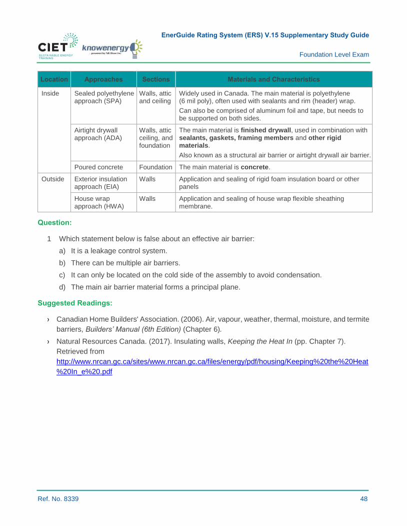
Location Approaches Sections Materials and Characteristics
Inside Sealed polyethylene approach (SPA)
Walls, attic and ceiling
Widely used in Canada. The main material is polyethylene (6 mil poly), often used with sealants and rim (header) wrap.
Can also be comprised of aluminum foil and tape, but needs to be supported on both sides.
Airtight drywall approach (ADA)
Walls, attic ceiling, and foundation
The main material is finished drywall, used in combination with sealants, gaskets, framing members and other rigid materials.
Also known as a structural air barrier or airtight drywall air barrier.
Poured concrete Foundation The main material is concrete.
Outside Exterior insulation approach (EIA)
Walls Application and sealing of rigid foam insulation board or other panels
House wrap approach (HWA)
Walls Application and sealing of house wrap flexible sheathing membrane.
Question:
1 Which statement below is false about an effective air barrier:
a) It is a leakage control system.
b) There can be multiple air barriers.
c) It can only be located on the cold side of the assembly to avoid condensation.
d) The main air barrier material forms a principal plane.
Suggested Readings:
› Canadian Home Builders' Association. (2006). Air, vapour, weather, thermal, moisture, and termite
barriers, Builders’ Manual (6th Edition) (Chapter 6).
› Natural Resources Canada. (2017). Insulating walls, Keeping the Heat In (pp. Chapter 7).
Retrieved from
http://www.nrcan.gc.ca/sites/www.nrcan.gc.ca/files/energy/pdf/housing/Keeping%20the%20Heat
%20In_e%20.pdf

EnerGuide Rating System (ERS) V.15 Supplementary Study Guide
Foundation Level Exam
Ref. No. 8339 49
Diagrams, Charts and Pictures:
Figure 13: Exterior vs. Interior Air Barriers16
Solution:
1. c)
16 Natural Resources Canada. (2017, 23 January). Thermal bridging and convection currents in the wall cavity [Online
picture]. Retrieved from https://www.nrcan.gc.ca/energy/efficiency/housing/home-improvements/keeping-the-heat-in/how-your-house-works/15630
EnerGuide Rating System (ERS) V.15 Supplementary Study Guide
Foundation Level Exam
Ref. No. 8339 50
5.2.7 DESCRIBE U-FACTOR
Key Concepts: Windows; U-factor; area/perimeter calculations.
Summary:
› The rate of heat loss is indicated in terms of the U-factor (U-value) of a window assembly.
› The lower the U-factor, the greater a window's resistance to heat flow and the better its insulating
properties.
› The U-factor measures the heat transfer per time, per area, and per degree of temperature
difference in W/m2·K (Btu/h ft2·°F).
Heat Loss Through Windows:
› Radiation: This causes about two-thirds of the total heat loss in a standard window. Because
ordinary glass readily emits heat to colder surfaces, radiation losses are reduced by lowering
glass emissivity.
› Conduction: Window frames and sashes are the primary elements that conduct heat. Advances
in technology and design that use insulating materials more effectively have dramatically reduced
heat losses from these sources.
› Convection: Air movement in the spaces between glass panes results in heat loss due to
convection. If the space is too small, conduction through the air is significant. If the air space is
too large, the still air rises as it is heated on the warm interior side and falls as it is cooled on the
cold exterior side of the window. This convection movement of air passes heat to the exterior. The
best spacing to minimize convection losses is 12 to 16 mm (1/2 in. to 2/3 in.) between glazings.
Gases (argon and krypton) are often used to reduce convection heat loss. Optimum spacing for
these gases varies.
› Air leakage: Air leakage is a significant contributor to energy costs during the heating and cooling
seasons. Most of the air leakage of operable windows (windows that can be opened) occurs
between the window sash and frame. Bigger windows tend to leak less air per unit area. Air
leakage can also occur in poorly constructed fixed windows between the insulated glass unit and
the frame. Windows that have the lowest leakage rates, regardless of the type, tend to be fixed
windows (i.e. they cannot be opened).
Windows also gain passive solar energy through glass to help offset energy costs during the heating
season. This balance is reflected in the energy-performance ratings.

EnerGuide Rating System (ERS) V.15 Supplementary Study Guide
Foundation Level Exam
Ref. No. 8339 51
The ENERGY STAR Residential Fenestration U-Factor Performance Metric:
› The U-factor multiplied by the interior-exterior temperature difference and by the projected
fenestration product area yields the total heat transfer through the fenestration.
› A U-factor in Btu/h ft.2·°F multiplied by 5.678263 converts the value to W/m2·K.
› The U-factor is also called the thermal transmittance value.
› The U-factor is one of the variables used to assess overall fenestration performance (see Learning
Objective 5.2.15: Describe Energy Rating).
› The lower the U-factor value, the better the product insulates.
› The U-factor is the reciprocal of R-value: U = 1/R.
How is the U-factor of ENERGY STAR Windows Calculated?
› U-factor values represent the rate of transfer of energy through conduction, convection and
radiation. U-factor values are determined using the NFRC Procedure for Determining Fenestration
Product U-factors.
› Window U-factor calculations include the following thermal transmittance (U-factor) components
and formula:
- Centre-of-glazing transmittance (or centre of glass in HOT2000);
- Edge-of-glazing transmittance (or centre of glass in HOT2000);
- Frame thermal transmittance.
𝑈𝑂𝑣𝑒𝑟𝑎𝑙𝑙 =(𝑈𝐹𝑟𝑎𝑚𝑒 × 𝐴𝐹𝑟𝑎𝑚𝑒) + (𝑈𝐸𝑑𝑔𝑒 × 𝐴𝐸𝑑𝑔𝑒) + (𝑈𝐺𝑙𝑎𝑠𝑠𝑧𝑖𝑛𝑔 × 𝐴𝐺𝑙𝑎𝑠𝑠𝑧𝑖𝑛𝑔)
(𝐴𝐹𝑟𝑎𝑚𝑒 + 𝐴𝐸𝑑𝑔𝑒 + 𝐴𝐺𝑙𝑎𝑧𝑖𝑛𝑔)
› ENERGY STAR® certified windows take into account the heat loss of the entire window assembly
(the overall U-factor).
› Energy efficiency metrics for the glass portion only, often called centre-of-glass ratings, make a
product seem more energy efficient than it is.
How to Improve the U-factor in Windows?
› To reduce conduction in windows, add frame thermal barriers.
› Increase the number of air spaces between the panes to reduce convection.
› Incorporate low-emissivity (low-e) coatings on glazing to minimize radiant heat loss.
› Substitute air with inert gas between the panes to reduce heat loss by convection within the
air spaces.
› Use windows made with insulated glass units equipped with insulating spacer bars.
EnerGuide Rating System (ERS) V.15 Supplementary Study Guide
Foundation Level Exam
Ref. No. 8339 52
Example:
Assume a window has the following characteristics:
R-value (hr.ft.2 °F/Btu) Area (ft.2)
Glazing 3.45 65%
Edge 2.94 15%
Frame 1.11 20%
Knowing that the total window area Atotal¸is equal to 24 ft.2, calculate the overall U-factor (Uoverall)
in W/m2.K.
Start by converting R-values to U-factors in W/m2.K and the different areas to m2:
We know that the U-factor equals 1/R-value and that the conversion factor from U to USI is: U x 5.678
We also know that the conversion from ft.2 to m2 is: m2 x 0.0929
Based on this information, here below are the new values:
U-factor (W/m2.K) Area (m2)
Glazing 1.64 1.46
Edge 1.93 0.33
Frame 5.11 0.44
Based on the converted values, calculate the Uoverall based on the Uoverall formula presented above:
𝑈 = 2.37 W/. K
Question:
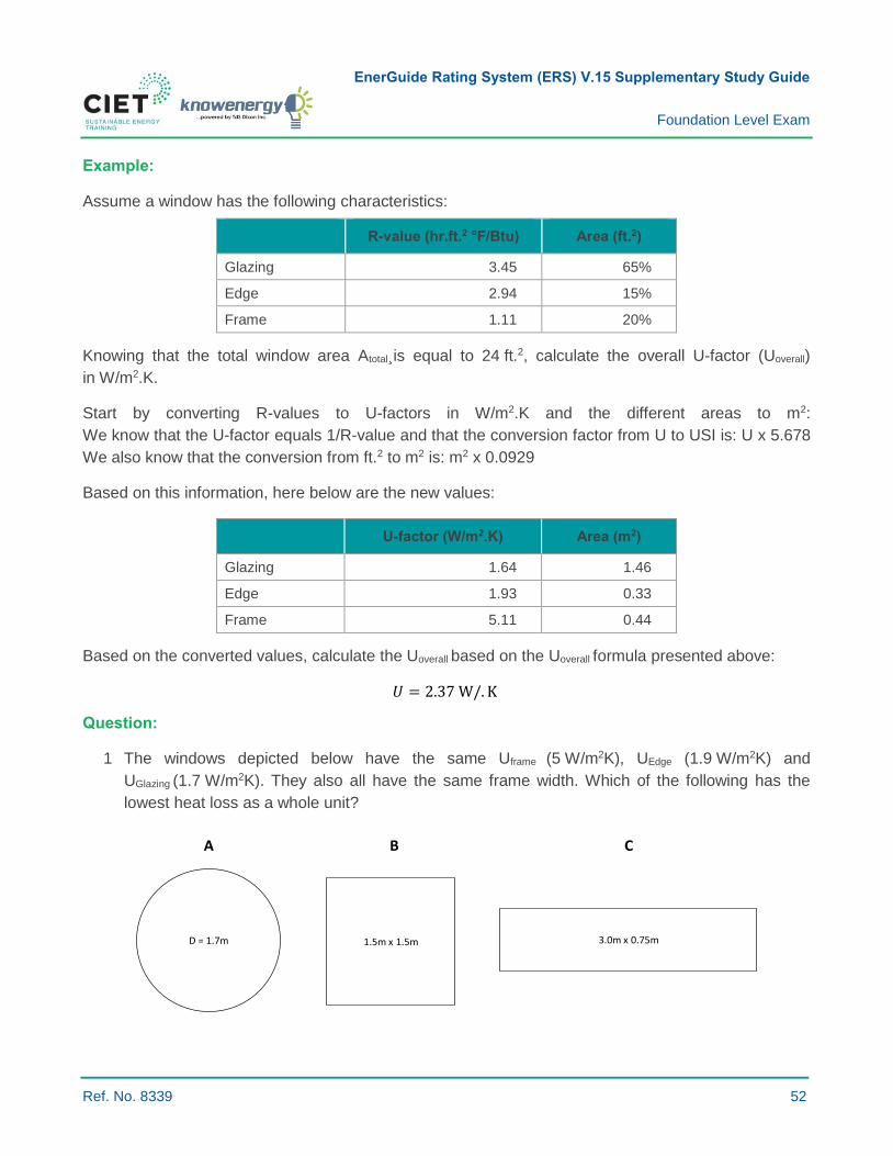
1 The windows depicted below have the same Uframe (5 W/m2K), UEdge (1.9 W/m2K) and
UGlazing (1.7 W/m2K). They also all have the same frame width. Which of the following has the
lowest heat loss as a whole unit?
1.5m x 1.5m 3.0m x 0.75mD = 1.7m
A B C

EnerGuide Rating System (ERS) V.15 Supplementary Study Guide
Foundation Level Exam
Ref. No. 8339 53
All dimensions are glazing dimensions.
a) Window A
b) Window B
c) Window C
d) They are all the same
Please see Learning Objective 2.1.2: Calculate Areas.
Suggested Readings:
› Canadian Home Builders' Association. (2006). Windows, Builders’ Manual (6th Edition)
(Subsection 13.1).
› Natural Resources Canada. (2009, 26 June). Personal: residential fenestration products, heat
loss through windows and doors. Retrieved from http://oee.nrcan-
rncan.gc.ca/residential/personal/windows-doors/heat-loss.cfm?attr=4
› Natural Resources Canada. (2009, 26 June). Fenestration technology, factors affecting energy
efficiency. Retrieved from www.nrcan.gc.ca/energy/products/categories/fenestration/14432
Glossary:
› Emissivity: The ratio of energy radiated from a material’s surface compared to a constant under
the same conditions.
› Operable windows: Windows that can be opened.
› Fixed windows: Windows that cannot be opened.
EnerGuide Rating System (ERS) V.15 Supplementary Study Guide
Foundation Level Exam
Ref. No. 8339 54
Diagrams, Charts, and Pictures:
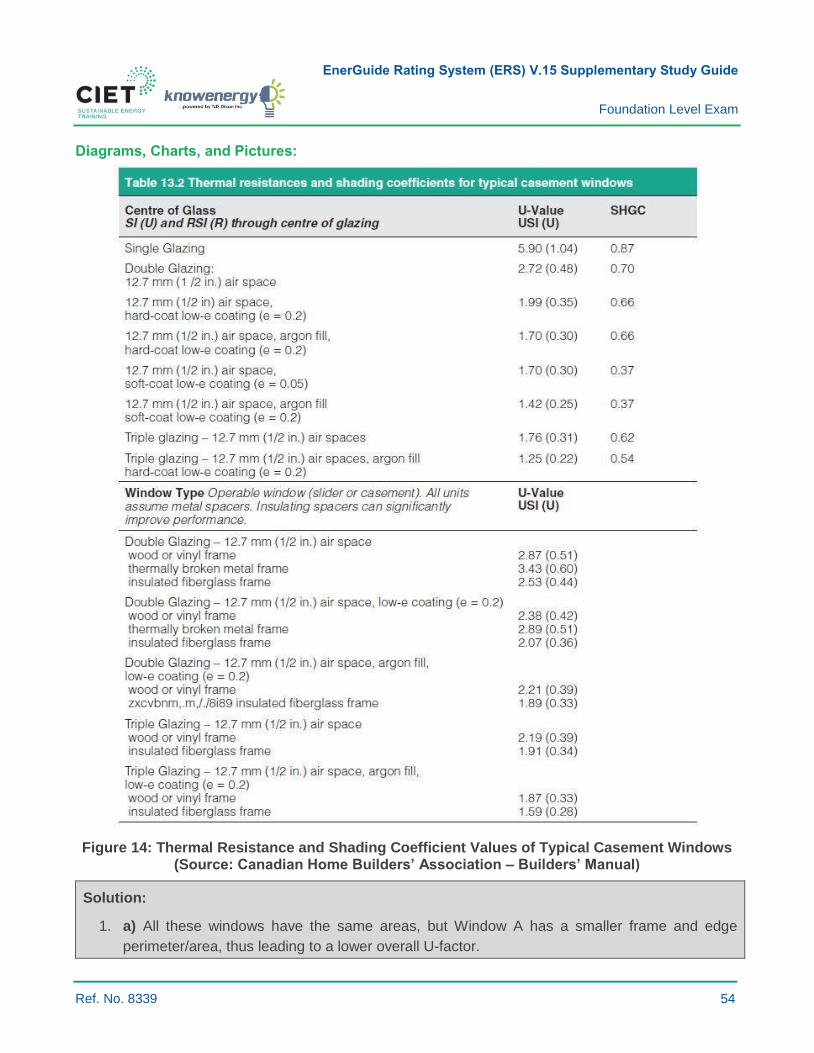
Figure 14: Thermal Resistance and Shading Coefficient Values of Typical Casement Windows (Source: Canadian Home Builders’ Association – Builders’ Manual)
Solution:
1. a) All these windows have the same areas, but Window A has a smaller frame and edge
perimeter/area, thus leading to a lower overall U-factor.
EnerGuide Rating System (ERS) V.15 Supplementary Study Guide
Foundation Level Exam
Ref. No. 8339 55
5.2.11 DESCRIBE LOW-E COATING
Key Concepts: Windows; low-e-coating; heat loss; window selection according to climate type.
Summary:
› Low-emissivity (low-e) coating allows light to pass through windows, but reduces radiation heat
losses or gains.
› It improves the window U-factor by limiting radiation losses.
- It is designed to reduce radiation heat loss in the winter and heat gain in the summer.
How Does Low-e Coating Work?
› Low-e coating is a thin metallic layer applied to the surface of glazing to improve
energy performance.
- It does so by reflecting the long-wave infrared radiation (heat) portion of the spectrum while still
allowing part of the solar spectrum to pass through it.
› Only a small portion of the solar spectrum is visible light, and how low-e coatings deal with the
remaining invisible portion of the solar spectrum varies.
- A low-solar-gain (LSG) coating reflects most of the invisible solar spectrum, helping to keep
solar gain to a minimum;
- A high-solar-gain (HSG) coating transmits most of the solar spectrum and accompanying
heat gain.
› The location of the coating also makes a difference.
- An LSG coating is typically located on exterior window panes to reflect heat out of buildings;
- An HSG coating is typically located on interior window panes to reflect heat toward the inside.
› In a northern climate, HSG windows allow more energy savings compared to LSG windows.
NRCan recommends using a combination of glazings for better results (e.g. LSG on the north and
HSG on the south).17
Example:
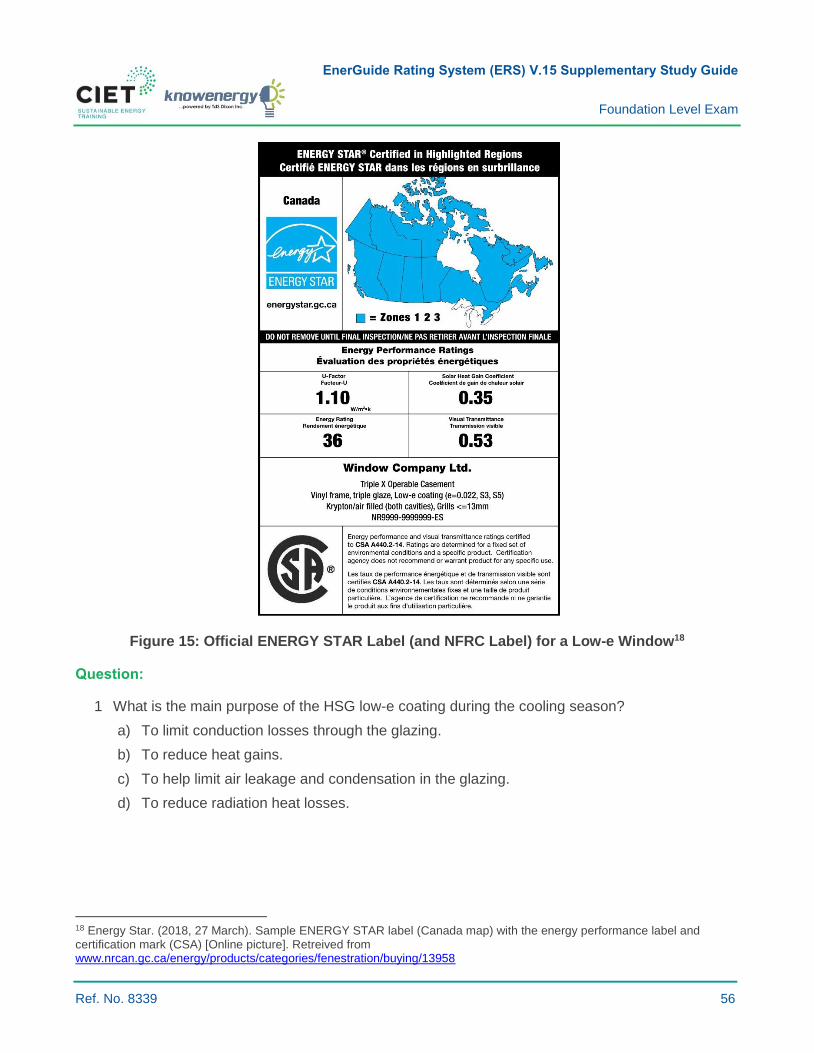
With a low-e coating, the U-factor value of a window with 12.7 mm spacing double glazing can be
improved from 2.72 W/m2K to 1.99 W/m2K. The figure below presents a specifications sheet of an
ENERGY STAR certified low-e window. The label contains information about the ENERGY STAR
Climate Zone and the retailer or manufacturer. The label also includes several characteristics of this
window, including the solar heat gain coefficient (SHGC), which is directly affected by the window’s solar
gain rate. The SHGC is a number between 0 and 1, with LSG products having an SHGC of less than
0.30 and HSG products having an SHGC greater than 0.30.
17 Natural Resouces Canada. (2014, 5 May). Low-Solar and High-Solar gain glazings. Retrieved from http://www.nrcan.gc.ca/energy/efficiency/housing/research/5139
EnerGuide Rating System (ERS) V.15 Supplementary Study Guide
Foundation Level Exam
Ref. No. 8339 56
Figure 15: Official ENERGY STAR Label (and NFRC Label) for a Low-e Window18
Question:
1 What is the main purpose of the HSG low-e coating during the cooling season?
a) To limit conduction losses through the glazing.
b) To reduce heat gains.
c) To help limit air leakage and condensation in the glazing.
d) To reduce radiation heat losses.
18 Energy Star. (2018, 27 March). Sample ENERGY STAR label (Canada map) with the energy performance label and certification mark (CSA) [Online picture]. Retreived from www.nrcan.gc.ca/energy/products/categories/fenestration/buying/13958
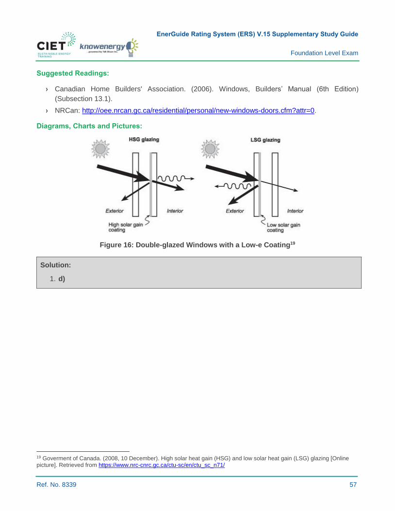
EnerGuide Rating System (ERS) V.15 Supplementary Study Guide
Foundation Level Exam
Ref. No. 8339 57
Suggested Readings:
› Canadian Home Builders' Association. (2006). Windows, Builders’ Manual (6th Edition)
(Subsection 13.1).
› NRCan: http://oee.nrcan.gc.ca/residential/personal/new-windows-doors.cfm?attr=0.
Diagrams, Charts and Pictures:
Figure 16: Double-glazed Windows with a Low-e Coating19
Solution:
1. d)
19 Goverment of Canada. (2008, 10 December). High solar heat gain (HSG) and low solar heat gain (LSG) glazing [Online picture]. Retrieved from https://www.nrc-cnrc.gc.ca/ctu-sc/en/ctu_sc_n71/

EnerGuide Rating System (ERS) V.15 Supplementary Study Guide
Foundation Level Exam
Ref. No. 8339 58
5.2.12 DESCRIBE GAS FILL AND TYPES
Key Concepts: Windows; inert gas, convection.
Summary:
› Non-reactive (safe) inert gases are filled into the space between glazings.
- Argon: Commonly used and cost effective;
- Krypton: Increased performance and allows smaller optimal spacing.
› Both inert gases reduce conduction heat loss because they both:
- Have a lower conductivity than air;
- Are heavier than air and suppress gas movement between the glazings.
› This method improves the glazing U-factor value.
› The percentage of gas fill may vary from one window product to another.
Heat Loss Through Windows
In general, the greatest loss occurs through the centre and edge of glass. For this reason, the glazing
is usually contained in something called an insulating glass (IG) unit which consists of at least two panes
of glass separated by a spacer bar and sealed around the edges to ensure airtightness. IG units are
typically filled with an inert gas, such as argon or krypton, to reduce heat transfer through the glazing.20
Air movement in the spaces between panes of glass results in heat loss through convection. If the space
is too small, conduction through the air is significant. If the air space is too large, the still air rises as it
is heated on the warm interior side and falls as it is cooled on the cold exterior side of the window. This
convection air movement passes heat to the exterior. The best spacing to minimize convection losses
is 12 to 16 mm (1/2 in. to 2/3 in.) between the glazings. Gases (e.g. argon and krypton) are often used
to reduce convection heat loss. Optimum spacing for these gases varies.
Over time, the inert gas used in an IG unit will dissipate. The rate at which this occurs depends on
manufacturing assembly processes, the quality of materials and its insulation, the building’s surrounding
environment including its exposure to sun and altitude, and other factors. According to some estimates,
gas-filled windows leak approximately one percent per year.21
20 Natural Resouces Canada. (2016, 11 August). Fenestration technology, factors affecting energy efficiency. Retrieved from http://www.nrcan.gc.ca/energy/products/categories/fenestration/14432 21 International Association of Certified Home Inspectors. (2018). Window gas fills: what inspectors and consumers should Know. Retrieved April 13, 2018, from https://www.nachi.org/window-gas-fills.htm
EnerGuide Rating System (ERS) V.15 Supplementary Study Guide
Foundation Level Exam
Ref. No. 8339 59
Note that window thermal performance remains adequate even after several years of gradual
depressurization. According to the National Glass Association, if 80 percent of the gas remains in spite
of gradual leakage over time, a window can be assumed to maintain its properties and effectiveness,2
thus yielding a window lifespan of nearly 20 years.
Refilling a gas-leaked window is possible by replacing worn or cracked seals. With a metering machine,
a specialist should be able to determine the volume of gas needed to refill the inner space between
glass panes. Refilling is accomplished using a special instrument that injects gas into the inner space
between glass panes. According to the Siding and Window Dealers Association of Canada (SAWDAC),
using argon gas instead of air provides increased insulation by about 30 percent and decreases
heat loss.22
Example:
› The centre-of-glass U-factor values of energy-efficient windows using available technology can be
reduced from 1.99 W/m2C for a standard double-glazed air-filled unit with a low-e coating to
1.70 W/m2C by using argon instead of air.
› According to the SAWDAC, by replacing drafty old windows with energy-efficient windows such
as Window Wise Approved units, a homeowner can save almost 60 percent of energy costs
related to heat lost through windows, or $180.00 per year.
Question:
1 Which of the following statements about argon-filled windows is true?
a) This method reduces radiation heat losses and improves the overall U-factor.
b) This method limits heat losses by suppressing gas movement between window panes.
c) This method reduces the risk of condensation between window panes.
d) These windows always have higher U-factors compared to krypton-filled windows.
Suggested Readings:
› Canadian Home Builders' Association. (2006). Windows, Builders’ Manual (6th Edition)
(Subsection 13.1).
› NRCan, Consumer’s Guide to Buying Energy-efficient Windows and Doors.
22 Siding and Window Dealers Association of Canada. (2018).Protecting consumersand helping renovatorsbuild better businesses. Retrieved April 13, 2018, from http://www.sawdac.com/FAQ.htm
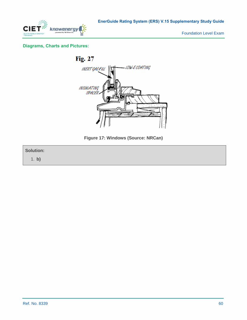
EnerGuide Rating System (ERS) V.15 Supplementary Study Guide
Foundation Level Exam
Ref. No. 8339 60
Diagrams, Charts and Pictures:
Figure 17: Windows (Source: NRCan)
Solution:
1. b)

EnerGuide Rating System (ERS) V.15 Supplementary Study Guide
Foundation Level Exam
Ref. No. 8339 61
5.2.15 DESCRIBE ENERGY RATING
Key Concepts: Windows, doors, skylights, fenestration systems, energy rating.
Summary:
› An energy rating (ER) for residential windows or doors is a measure of performance based on
three factors: (1) heat loss (U-Factor); (2) air leakage loss; and (3) potential passive solar gain of
a fenestration product.
› The ER is applied to fenestration systems intended to be vertically installed in low-rise residential
buildings (skylights are not included).
› The higher the ER, the more potential energy gains the product will allow.
› Higher ER indicate a slower heat transfer without significantly reducing the amount of solar gain.
The Canadian Residential Fenestration Energy Rating:
In Canada, the residential fenestration Energy Rating is calculated by applying the following equation
and constants:
› The Energy Rating (ER) is a unitless value derived from a formula that balances heat loss, air
leakage loss, and the potential passive solar gain of fenestration products. The simplified ER
equation is as follows:
𝐸𝑅 = (57.76 × 𝑆𝐻𝐺𝐶𝑤) − (21.90 × 𝑈𝑤) − (1.97 × 𝐿𝑤) + 40
Where:
› SHGCw = fenestration system solar heat gain coefficient.
› Uw = fenestration system U-factor (W/m2).
› Lw = fenestration system air leakage rate at a pressure difference of 75 Pa, established in
accordance with AAMA/WDMA/CSA 101/I.S.2/A440 (North American Fenestration Standard) in
L/s•m2. L75 shall be the average of infiltration and exfiltration measurements.
A complete explanation of the ER equation is outlined in the CSA A440.2 Standard.
› U-factor is the heat transfer per time, per area, and per degree of temperature difference in
W/m2·K (Btu/h ft.2·°F). A U-factor in Btu/h ft.2·°F multiplied by 5.678263 converts the value to
W/m2·K. See Learning Objective 5.2.7 for more detail.
› Solar heat gain coefficient (SHGC) is the ratio, expressed as a value between 0 and 1, of the
solar heat gain entering space through fenestration products to the incident solar radiation.
The Air Leakage metric is the flow of air that passes through fenestration products in L/s/m2. Air leakage
infiltration is the flow of air into the building envelope and exfiltration is the flow of air out of the building
envelope. Multiplying air leakage in cfm/ft.2 by 5.08 converts the value to L/s/m2.
EnerGuide Rating System (ERS) V.15 Supplementary Study Guide
Foundation Level Exam
Ref. No. 8339 62
Related Concept:
› Visible transmittance (VT) is a fraction of incident visible light that passes through fenestration
products expressed as a value from 0 to 1. The higher this value, the more light passes through
fenestration products.
Question:
1 Which of the following statements is true about residential Fenestration Energy Ratings?
a) A negative rating indicates that heat gains are superior to heat losses.
b) It represents a window’s overall heat loss coefficient expressed in W/m2K or in Btu/(hr)(ft.2)(°F).
c) It is adversely affected by air exfiltration only.
d) ER ratings do not apply to skylights.
Suggested Readings:
ENERGY STAR®. Natural Resources Canada.
› Natural Resouces Canada. (2016, 11 August). Summary of qualifications—windows, doors and
skylights. Retrieved from http://www.nrcan.gc.ca/energy/products/categories/fenestration/13951
› Natural Resouces Canada. (2018, 21 February). Fenestration (windows and doors). Retrieved
from http://www.nrcan.gc.ca/energy/products/categories/fenestration/13739.
› Natural Resouces Canada. (2017, 31 January). Window, door and skylights—residential, sold in
Canada—ENERGY STAR technical specifications. Retrieved from
http://www.nrcan.gc.ca/energy/products/for-participants/specifications/13720
Solution:
1. d)

EnerGuide Rating System (ERS) V.15 Supplementary Study Guide
Foundation Level Exam
Ref. No. 8339 63
5.2.17 DESCRIBE ENERGY STAR® RATINGS AND PERFORMANCE FOR WINDOWS AND DOORS
Key Concepts: Windows, efficiency, Energy Star, zones.
Summary
ENERGY STAR certified windows, doors and skylights have special features to reduce energy loss
and condensation.
Compliance:
› The compliance path is divided into three climate zones for Canada:
- Zone 3: >= 6,000 HDDs;23
- Zone 2: >= 3,500 to < 6,000 HDDs;
- Zone 1: < 3,500 HDDs.
› Compliance is based on the U-factor (see Learning Objective 5.2.7) or the energy rating (see
Learning Objective 5.2.15)
Zone
Compliance Path
Energy Rating (ER) or U-factor
Minimum ER (unitless) or Maximum U-factor W/m2•K
(Btu/h•ft.²•°F)
and Minimum ER (unitless) Windows and Sliding Glass
Doors Only
1 25 or 1.60 (0.28) and 16
2 29 or 1.40 (0.25) and 20
3 34 or 1.20 (0.21) and 24
Homeowners or builders should carefully select windows and doors. Choosing non-compliant materials
for their respective zones will not pass minimum criteria and be rejected. It is always best to consult an
industry professional to balance performance, building code, and cost requirements.
Fenestration products may be ENERGY STAR certified if they have:
› A high ER that balances heat loss with heat gain. The higher the ER value, the more the product
is energy efficient. (ER ratings do not apply to skylights.)
› A low U-factor which measures the rate of heat transfer. The lower the U-factor value, the better
the product insulates.
› Windows, doors and skylights must have an air leakage value of 1.5 L/s/m2 or less.
23 Heating Degree Days (HDDs) are the equivalent number of heating days for a building by 1 degree to cover the heating requirement. As an example, if the external temperature is 55°F degrees and the set temperature is 65°F, the HDDs are equal to 10 because the outside temperature is 10 degrees below the set temperature. For this case, the HDDs were calculated on a yearly basis.
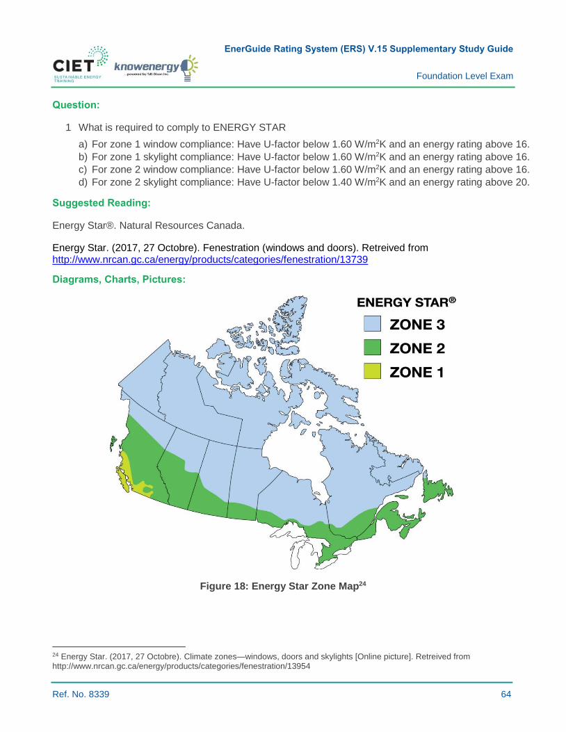
EnerGuide Rating System (ERS) V.15 Supplementary Study Guide
Foundation Level Exam
Ref. No. 8339 64
Question:
1 What is required to comply to ENERGY STAR
a) For zone 1 window compliance: Have U-factor below 1.60 W/m2K and an energy rating above 16.
b) For zone 1 skylight compliance: Have U-factor below 1.60 W/m2K and an energy rating above 16.
c) For zone 2 window compliance: Have U-factor below 1.60 W/m2K and an energy rating above 16.
d) For zone 2 skylight compliance: Have U-factor below 1.40 W/m2K and an energy rating above 20.
Suggested Reading:
Energy Star®. Natural Resources Canada.
Energy Star. (2017, 27 Octobre). Fenestration (windows and doors). Retreived from http://www.nrcan.gc.ca/energy/products/categories/fenestration/13739
Diagrams, Charts, Pictures:
Figure 18: Energy Star Zone Map24
24 Energy Star. (2017, 27 Octobre). Climate zones—windows, doors and skylights [Online picture]. Retreived from http://www.nrcan.gc.ca/energy/products/categories/fenestration/13954

EnerGuide Rating System (ERS) V.15 Supplementary Study Guide
Foundation Level Exam
Ref. No. 8339 65
Figure 19: Energy Star Label25
Solution:
1. a)
25 Energy Star. (2018, 27 March). Sample ENERGY STAR label (Canada map) with the energy performance label and certification mark (CSA) [Online picture]. Retreived from www.nrcan.gc.ca/energy/products/categories/fenestration/buying/13958

EnerGuide Rating System (ERS) V.15 Supplementary Study Guide
Foundation Level Exam
Ref. No. 8339 66
6.1.2 DESCRIBE OUTDOOR DESIGN TEMPERATURE
Key Concepts: Equipment sizing; operational peak conditions; outdoor design temperature.
Summary:
› Operational peak conditions are established at the design stage of cooling and heating equipment.
› Outdoor design conditions are outlined in the National Building Code (NBC) for several cities
across Canada and are based on historical data, usually covering an average 30-year period, from
weather stations.
› Based on annual occurrences of 99.6 percent or 99 percent.
- A 99 percent winter design temperature for a given location means that the outdoor temperature
is above the design temperature for 99 percent of all the hours in the year;
- In the winter, this means that a heating system inside a building or home does not meet the
thermostat set-point temperature for a few hours;
- A home’s thermal inertia helps absorb the effects of many short peak weather conditions.
Equipment Sizing:
› Heating and cooling equipment should be sized to optimize comfort, costs, operational
effectiveness, and efficiency.
› Oversized equipment has a higher cost and operates less efficiently, whereas undersized
equipment does not meet the required comfort level for homes.
› Equipment capacity should be sized according to the guidelines outlined in CSA F280 Determining
the Required Capacity of Residential Space Heating and Cooling Equipment Appliances.
Operational Peak Conditions:
› Since extreme peak weather conditions in a given location usually occur once every other year
and only for a few hours, heating and cooling equipment is usually sized to meet energy load
requirements for a certain number of hours during the year.
› Trying to meet the full requirements associated with extreme weather would mean oversizing
equipment and incurring unnecessarily high costs just to maintain comfort levels for a few hours.
› To achieve higher efficiency, systems with modulating or multi-stage capacities should be selected
to meet partial heating loads since equipment rarely runs at full capacity.
EnerGuide Rating System (ERS) V.15 Supplementary Study Guide
Foundation Level Exam
Ref. No. 8339 67
Example:
› For a 99 percent winter design temperature, the outdoor temperature is colder than the design
temperature for only one percent of the hours in a year on average or about 88 hours per year.
› Maximum heating system efficiency occurs when equipment is operating at full load (e.g. a
conventional non-condensing boiler has an efficiency of 82 percent at 90 percent load and only
46 percent at 10 percent load).
› A system designed to meet the coldest temperature in a year operates at partial operating
conditions more often, leading to lower efficiency and higher losses.
Question:
1 What is the winter outdoor design temperature?
a) The lowest possible temperature that can be expected during a winter.
b) The temperature below which heating equipment starts supplying heat.
c) The temperature below which heating equipment cannot meet indoor temperature set-points.
d) The temperature at which heating equipment should be operating at peak efficiency.
Suggested Readings:
› Canadian Home Builders' Association. (2006). Heating and Cooling Design Loads, Builders’
Manual (6th Edition) (Subsection 15.2).
› American Society of Heating, Refrigerating and Air-Conditioning Engineers, Inc. (ASHRAE).
(2009). Climatic Design Information. ASHRAE Fundamentals Handbook 2009 SI. USA: ASHRAE
› National Research Council Canada. (2015). National Building Code of Canada. Ottawa: National
Research Council Canada.
› Canadian Standards Association. (2017). Determining the Required Capacity of Residential
Space Heating and Cooling Equipment Appliances. Retrieved from
http://shop.csa.ca/en/canada/energy-efficiency/f280-12-r2017-/invt/27006132012
Solution:
1. c)
EnerGuide Rating System (ERS) V.15 Supplementary Study Guide
Foundation Level Exam
Ref. No. 8339 68
6.1.3 DESCRIBE HEATING LOAD
Key Concepts: Heating load; heat load calculations; air infiltration load; secondary/auxiliary
heating equipment.
Summary:
› The heating load is the power [kW or Btu/h] required to maintain indoor temperature set-points
associated with given outdoor conditions.
› The heating load is used to describe heat loss which is the sum of:
- The heat transmitted through walls, ceilings, floors, glass and other surfaces; and
- The heat required to temper outdoor air entering a structure through infiltration and ventilation.
› A calculated heat load does not need to include the impact of a structure’s thermal mass. During
the coldest hours of the night, peak heat loss is considered equivalent to peak heat load. The
coldest period of the day is in the early morning.
› Tip: The impact of a building’s thermal mass, or conduction transients, should be considered when
calculating the cooling load (see Learning Objective 6.1.4 on cooling load).
Proper Sizing of Equipment According to Outdoor and Indoor Design Conditions:
› Heating systems should provide enough heat at maximum capacity to compensate for peak
heat losses.
› Not meeting design conditions during short periods should be allowed for residential buildings.
(See Learning Objective 6.1.2 on outdoor design temperature).
Heat Load Calculations:
› Heat load calculations are designed to estimate the heat loss of a home, or a particular space
inside a home, at peak design conditions and to determine the required heating and humidification
capacity of mechanical equipment.
› These calculations are usually performed not only on a room-by-room basis to estimate the output
capacity required by a heating system such as electric baseboards or distributed systems such as
heating cabinets, but also on a whole-house basis to estimate the required full heating load of
centralized systems.
› Several computer programs can be used to calculate heat load. Designers must have thorough
knowledge of which factors impact a building’s heat load to develop accurate computer-
generated analyses.
EnerGuide Rating System (ERS) V.15 Supplementary Study Guide
Foundation Level Exam
Ref. No. 8339 69
Transmission Heat Loss
Transmission (conduction through the envelope) heat loss is calculated by adding up the transmission
heat losses through the various envelop components (walls, floor, roof, etc.). Each component’s heat
loss is estimated by using the heat transfer coefficient U [W/m²·°C or Btu/h·ft.²·°F] and area A [m² or ft²]
of the component as per the following equation:
�̇�𝑡[𝑊] = 𝑈 [𝑊
m² · °𝐶] × 𝐴[𝑚2] × (𝑇𝑖𝑛𝑑𝑜𝑜𝑟 − 𝑇𝑜𝑢𝑡𝑑𝑜𝑜𝑟)
Where:
› �̇�𝑡 = Transmission heat loss W or Btu/h.
› 𝑇𝑖𝑛𝑑𝑜𝑜𝑟 = Indoor air temperature °C or °F.
› 𝑇𝑜𝑢𝑡𝑑𝑜𝑜𝑟 = Outdoor air temperature °C or °F.
› U = Heat transfer coefficient U [W/m²·°C] or [Btu/h/ft.²·°F].
As for walls, the heat transfer coefficient U [W/m²·°C] is calculated using the sum of the materials’ R-
values (m²·°C/W], including insulation caused by indoor and outdoor films of air.
𝑈 [𝑊
m² · °𝐶] =
1
𝑅𝑒𝑓𝑓𝑒𝑐𝑡𝑖𝑣𝑒 [m² · °𝐶
𝑊 ]
For Reffective calculations, please see Learning Objective 7.2.19.
Infiltration and Ventilation:
› Air infiltration is caused by discontinuity in the air barrier system, i.e. poor installation, through
cracks around doors, windows, lighting and electrical fixtures, joints between walls and the floor,
and to a lesser extent through building materials.
› The amount of infiltration depends on the total area, types of cracks and pressure difference on
each side of cracks, which in turn depends on wind speeds, indoor-outdoor air pressure
differences and outdoor temperature.
› Lower outdoor temperatures cause higher infiltration due to stack effects.
› Air infiltration and ventilation is expressed in indoor air changes per hour.
› The infiltration rate is calculated using the following equation:
�̇� = (𝐴𝐶𝐻)(𝑉)/𝐶𝑇 Where:
› �̇� = Infiltration rate, cfm or m³/s.
› 𝐴𝐶𝐻 = Number of air changes per hour, hr-1.
› 𝑉 = Gross space volume, ft.³ or m³.
› 𝐶𝑇 = Constant; 60 for imperial units and 3,600 for SI units.
EnerGuide Rating System (ERS) V.15 Supplementary Study Guide
Foundation Level Exam
Ref. No. 8339 70
The heat required to bring outdoor air to indoor ambient conditions, also called the sensible heat loss,
is calculated by applying the specific heat of air, the specific volume of air, and air changes per hour by
using the following equation:
�̇�𝑠 =�̇�
𝑣0𝑐𝑝(𝑇𝑖𝑛𝑑𝑜𝑜𝑟 − 𝑇𝑜𝑢𝑡𝑑𝑜𝑜𝑟)
Where:
› �̇� = Infiltration rate, cfm or m³/s.
› �̇�𝑠 = Sensible heat loss, Btu/h or W.
› 𝑐𝑝 = Specific heat (Cp) of air at room temperature and atmosphere is (SI) 1.01 (kJ/kg K) or 0.24
Btu/(lbm·°F).
› 𝑣0 = Specific volume, ft.³ or m³/kg.
Example:
› A room inside a home has two exterior walls, one is 3 m × 2.74 m and the other is 4 m x 2.74 m,
with all other interior walls, the ceiling and floor being adjacent to conditioned spaces. The home
has two standard wood windows each with a size of 0.8 m × 1.2 m, double glazing, and 12.7 mm
of air space.
› Design conditions are -18°C indoors and 21°C outdoors.
› The windows’ U-factor is 2.87 W/m²·C°.
› The effective R-value of the wall is 2.81 (m²·°C)/W.
› No infiltration is considered and radiation losses from walls are neglected.
› Determine the heating capacity required by a decentralized heating cabinet for the room.
Answer:
› 𝐴𝑤𝑖𝑛𝑑𝑜𝑤𝑠 = 1.92 m² (including both windows).
› 𝐴𝑤𝑎𝑙𝑙 = 17.26 m² (excluding windows).
› ∆t = 38°C.
› �̇�𝑡[𝑊] = 2.87𝑊
m²·°𝐶× 1.92 𝑚2 × 38°𝐶 +
1
2.81
𝑊
m²·°𝐶× 17.26 𝑚2 × 38°𝐶.
› �̇�𝑡[𝑊] = 209 𝑊 + 233 𝑊 = 442 𝑊.
Question:
1 Which of the following statements is true regarding the peak heating load requirements of a home?
a) Is it always cost effective for a geothermal system to be sized to meet the full heating load.
b) Thermal bridging cannot be neglected when calculating heating loads because it accentuates
heat transfer.
c) Lower U-values lead to higher heating loads.
d) When a central heating system is used, the heating load is the same for all the rooms of
a house.

EnerGuide Rating System (ERS) V.15 Supplementary Study Guide
Foundation Level Exam
Ref. No. 8339 71
Suggested Readings:
› Canadian Home Builders' Association. (2006). Heating and Cooling Design Loads, Builders’
Manual (6th Edition) (Subsection 15.2).
› CSA F280 Determining the Required Capacity of Residential Space Heating and Cooling
Equipment Appliances.
› ASHRAE Cooling and Heating Load Calculation Manual.
› HRAI Residential Heat Loss & Heat Gain Worksheet,
http://www.hrai.ca/uploads/userfiles/files/RHLHG_Worksheet_Jul2017.pdf.
Solution:
1. b)
EnerGuide Rating System (ERS) V.15 Supplementary Study Guide
Foundation Level Exam
Ref. No. 8339 72
6.1.4 DESCRIBE COOLING LOAD
Key Concepts: Cooling load; cooling load calculations; reducing the cooling load; proper sizing
of equipment.
Summary:
› The cooling load is the power [kW or Btu/h] required to maintain the indoor temperature set-points
associated with given outdoor conditions.
› Cooling is used to:
- Mitigate heat gains transmitted through surfaces and solar heat gains; and
- Cool and dry outdoor air entering a home (infiltration and ventilation).
› The cooling load usually differs from the instantaneous or transient heat gains due to a structure’s
thermal mass. The thermal mass makes the structure less sensitive to transient effects and may
reduce the peak cooling load. The impact of a building’s thermal mass on the peak cooling load is
significant because the peak heat gain occurs over a limited period of time during the day.
The Cooling Load:
› Cooling equipment provides dehumidification by condensing water vapour out of the air.
› The cooling load is the rate at which energy needs to be removed from a space to maintain the
temperature and humidity within an acceptable range.
› Heat gain has two components, sensible heat and latent heat (see the glossary further below
for definitions).
› The cooling load usually differs from the instantaneous or transient heat gains because of transient
effects or the time delay caused by convection effects, radiative effects, and heat storage in the
furnishings and building.
› This thermal lag defines the relationship between the heat gain and cooling load.
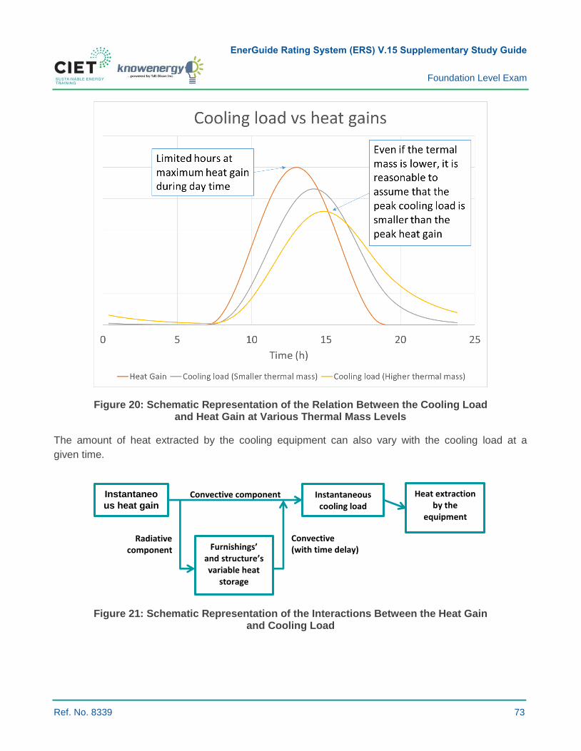
EnerGuide Rating System (ERS) V.15 Supplementary Study Guide
Foundation Level Exam
Ref. No. 8339 73
Figure 20: Schematic Representation of the Relation Between the Cooling Load and Heat Gain at Various Thermal Mass Levels
The amount of heat extracted by the cooling equipment can also vary with the cooling load at a
given time.
Figure 21: Schematic Representation of the Interactions Between the Heat Gain and Cooling Load
Radiative component
Convective (with time delay)
Convective component Instantaneo
us heat gain Instantaneous
cooling load Heat extraction
by the equipment
Furnishings’ and structure’s variable heat
storage

EnerGuide Rating System (ERS) V.15 Supplementary Study Guide
Foundation Level Exam
Ref. No. 8339 74
Proper Equipment Sizing According to Outdoor and Indoor Design Conditions:
› Cooling equipment should be appropriately sized according to the expected cooling load
associated with outdoor design conditions (see Learning Objective 6.1.2 on outdoor
design temperature).
› Significantly undersized cooling equipment cannot provide the required comfort to occupants,
whereas oversized cooling equipment is unnecessarily expensive, works less efficiently and
cannot provide the required level of dehumidification.
Cooling Load Calculations:
› Cooling load calculations need to take into account:
- Solar heat gains via fenestrations;
- Heat transfer through the building envelope;
- Heat and moisture from outdoor air by means of natural infiltration and mechanical ventilation;
- Heat generated by appliances, equipment, and lighting;
- Heat and moisture generated by occupants and activities.
› Several computer design programs are available to estimate a building’s cooling load. Designers
must have thorough knowledge of which factors impact a building’s cooling load to develop
accurate computer-generated analyses.
› To take into consideration heat transfer through the envelope, infiltration and ventilation, cooling
load calculations are performed using a process similar to the one detailed in Learning Objective
6.1.3 on heating load. To determine solar heat gain through windows, exterior shading must be
taken into account.
Reducing the Cooling Load:
› The following serve to reduce the cooling load and downsize or eliminate (in some milder climates)
the need for cooling equipment:
- Proper orientation and positioning of windows;
- Exterior shading with permanent structure or proper overhang;
- Increased reflectivity of the roof and outdoor surfaces;
- Increased air tightness;
- Proper ventilation rate;
- Use of efficient heat recovery ventilators and energy recovery ventilators (HRV/ERVs);
- Proper attic venting;
- Highly efficient building envelopes.

EnerGuide Rating System (ERS) V.15 Supplementary Study Guide
Foundation Level Exam
Ref. No. 8339 75
Question:
1 Which of the following statements is false regarding the cooling load:
a) The peak cooling load occurs during the peak heat gain period of the day.
b) The cooling load represents the heat extraction rate required to meet given indoor conditions.
c) The cooling load can be expressed in W or Btu/h.
d) Limiting air infiltration can reduce the cooling load.
Suggested Readings:
› Canadian Home Builders' Association. (2006). Energy Source Selection, Builders’ Manual (6th
Edition) (Subsection 15.4).
› CSA, F280, Determining the Required Capacity of Residential Space Heating and Cooling
Equipment Appliances.
› ASHRAE, Cooling and Heating Load Calculation Manual.
› Faye C. McQuiston, Jerald D. Parker, and Jeffrey D. Spitler. Heating, Ventilation and
Air-conditioning Analysis and Design. Sixth Edition. Wiley. 2005. pp. 216-278.
› HRAI Worksheet.
Solution:
1. a)
EnerGuide Rating System (ERS) V.15 Supplementary Study Guide
Foundation Level Exam
Ref. No. 8339 76
6.1.5 DISTINGUISH BETWEEN A UNIT OF ENERGY AND A UNIT OF POWER
Key Concepts: Energy; power; rate of energy consumption; units of energy; units of power; efficiency;
capacity; maximum power input; utility bills; smart meters.
Summary:
Power is the rate at which energy is produced, consumed, or transmitted.
Energy vs. Power:
› Energy is the ability to do work.
- In physics, work is an applied force multiplied by the distance over which it is applied.
› Power is the rate at which energy is produced, consumed, or transmitted per unit of time.
- In physics, power is the rate at which work is performed or an equivalent measure of how
quickly work is accomplished.
› Energy consumption is obtained by multiplying the power input of a system by the amount of time
that this system runs.
Table 3: Concept Summary of Force, Energy, and Power
Concepts Units
Force (e.g. gravity) kg·m/s² or Newton
Work = Force × Distance kg·m²/s² = J
Energy J
Power J/s
Units of Energy and Power
Common units of energy and power are listed in the table below.
Table 4: Common Units of Energy and Power
Units of Energy Units of Power
Joules (J) Joules per second (J/s)
Kilowatt-hours (kWh) Kilowatt (kW) or Watt (W)
British thermal unit (Btu) British thermal unit per hour (Btu/h)
Calories (Cal) Calories per day (Cal/day)
Horsepower
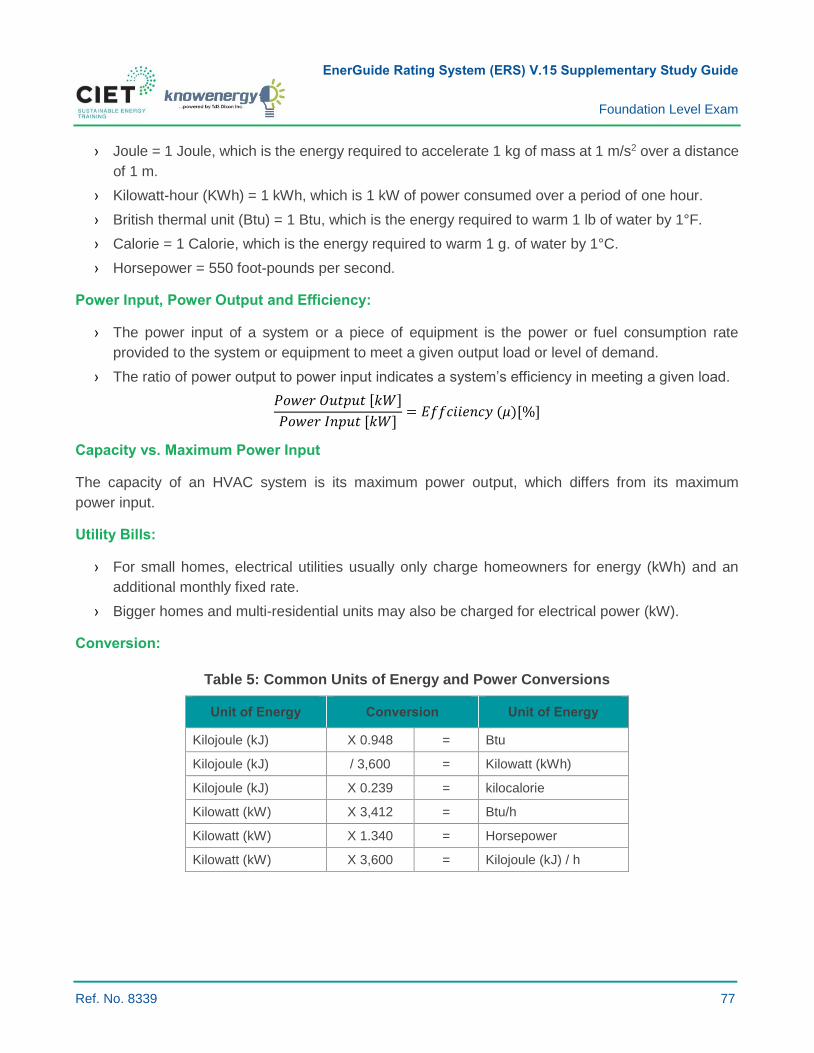
EnerGuide Rating System (ERS) V.15 Supplementary Study Guide
Foundation Level Exam
Ref. No. 8339 77
› Joule = 1 Joule, which is the energy required to accelerate 1 kg of mass at 1 m/s2 over a distance
of 1 m.
› Kilowatt-hour (KWh) = 1 kWh, which is 1 kW of power consumed over a period of one hour.
› British thermal unit (Btu) = 1 Btu, which is the energy required to warm 1 lb of water by 1°F.
› Calorie = 1 Calorie, which is the energy required to warm 1 g. of water by 1°C.
› Horsepower = 550 foot-pounds per second.
Power Input, Power Output and Efficiency:
› The power input of a system or a piece of equipment is the power or fuel consumption rate
provided to the system or equipment to meet a given output load or level of demand.
› The ratio of power output to power input indicates a system’s efficiency in meeting a given load.
𝑃𝑜𝑤𝑒𝑟 𝑂𝑢𝑡𝑝𝑢𝑡 [𝑘𝑊]
𝑃𝑜𝑤𝑒𝑟 𝐼𝑛𝑝𝑢𝑡 [𝑘𝑊]= 𝐸𝑓𝑓𝑐𝑖𝑖𝑒𝑛𝑐𝑦 (𝜇)[%]
Capacity vs. Maximum Power Input
The capacity of an HVAC system is its maximum power output, which differs from its maximum
power input.
Utility Bills:
› For small homes, electrical utilities usually only charge homeowners for energy (kWh) and an
additional monthly fixed rate.
› Bigger homes and multi-residential units may also be charged for electrical power (kW).
Conversion:
Table 5: Common Units of Energy and Power Conversions
Unit of Energy Conversion Unit of Energy
Kilojoule (kJ) X 0.948 = Btu
Kilojoule (kJ) / 3,600 = Kilowatt (kWh)
Kilojoule (kJ) X 0.239 = kilocalorie
Kilowatt (kW) X 3,412 = Btu/h
Kilowatt (kW) X 1.340 = Horsepower
Kilowatt (kW) X 3,600 = Kilojoule (kJ) / h

EnerGuide Rating System (ERS) V.15 Supplementary Study Guide
Foundation Level Exam
Ref. No. 8339 78
The Load Factor:
› The load factor is the ratio of average power to peak power for a specific period of time.
› To size a house’s main electrical panel, the peak power is required.
› A small load factor means that the house electrical system is underutilized.
𝐿𝐹 =𝑘𝑊ℎ/ℎ
𝑘𝑊𝑃𝑒𝑎𝑘
Where:
› 𝐿𝐹 = Load factor for a specific period.
› 𝑘𝑊ℎ = Energy consumed over a specific period.
› ℎ = Duration of the period.
› 𝑘𝑊𝑃𝑒𝑎𝑘 = Peak power consumption during the period.
Example:
› A 60 W (power) light bulb running for 30 days incurs an electricity bill of 43.2 kWh (energy).
› A battery has a capacity of 500 amps (A) of current at 12 volts (V); it can thus provide 6 kW
of power.
› It takes 100 kilocalories (418.4 KJ or 396 Btu or 0.1162 kWh) to warm 1 kg of water (1L) from 0°C
to 100°C.
- The power required to achieve this in 1 minute is 6.970 W = 0.1162 kWh/(1/60)h and in
10 minutes is 0.697 W = 0.1162 kWh/(10/60)h.
Question:
1 You have a BBQ with a maximum heat output of 30,000 Btu/h (power); what is the equivalent
in W?
a) 8,800 W.
b) 8,400 W.
c) 28,400 W.
d) Btu/h is energy, while W is power.
Suggested Readings:
› Canadian Home Builders' Association. (2006). Energy Source Selection, Builders’ Manual (6th
Edition) (Subsection 15.4).
› Faye C. McQuiston, Jerald D. Parker, and Jeffrey D. Spitler. Heating, Ventilation and Air-
conditioning Analysis and Design. Sixth Edition. Wiley. 2005. Page 4.
Solution:
1. a)
EnerGuide Rating System (ERS) V.15 Supplementary Study Guide
Foundation Level Exam
Ref. No. 8339 79
6.1.6 INTERPRET THE TERMINOLOGY USED TO MEASURE THE ENERGY EFFICIENCY OF VARIOUS TYPES OF MECHANICAL SYSTEMS
Key Concepts: Energy efficiency ratings; annual fuel utilization efficiency (AFUE); coefficient of
performance (COP); heating seasonal performance factor (HSPF); energy efficiency ratio (EER);
seasonal energy efficiency ratio (SEER).
Summary:
› Mechanical system energy efficiency is usually based on the ratio of energy output, or work
performed by a piece of equipment, to the amount of energy input.
› Different terms are used for different systems to characterize efficiency.
› Authorities use HVAC system energy efficiency ratings to set minimum energy efficiency
standards for equipment.
› Consumers compare product energy efficiency ratings and buy those products that are the most
energy efficient.
Cooling and Heating Capacity:
› Cooling capacity is a piece of equipment’s maximum cooling power output under
specified conditions.
› Heating capacity is a piece of equipment’s maximum heating power output under
specified conditions.
› These capacities differ from maximum electrical power input and the maximum fuel
consumption rate.
HVAC System Energy Efficiency Ratings:
› Used by authorities and associations to set product category minimum efficiency standards which
manufacturers must meet.
› Minimum efficiency standards have become increasingly stringent over the years to account for
technological advances and force the market to improve efficiency.
› Minimum efficiency ratings are usually established by energy type, equipment category and size,
or capacity category.

EnerGuide Rating System (ERS) V.15 Supplementary Study Guide
Foundation Level Exam
Ref. No. 8339 80
Table 6: Energy Efficiency Ratings and Equations
Energy Efficiency Rating Equation
Annual Fuel Utilization Efficiency (AFUE) 𝐴𝐹𝑈𝐸 [%] =
𝐸𝑛𝑒𝑟𝑔𝑦 𝑜𝑢𝑡𝑝𝑢𝑡 [𝐵𝑡𝑢]
𝐸𝑛𝑒𝑟𝑔𝑦 𝑖𝑛𝑝𝑢𝑡 [𝐵𝑡𝑢]
Coefficient of Performance (COP) 𝐶𝑂𝑃 [
𝑊
𝑊] =
𝑃𝑜𝑤𝑒𝑟 𝑜𝑢𝑡𝑝𝑢𝑡 [𝑊]
𝑃𝑜𝑤𝑒𝑟 𝑖𝑛𝑝𝑢𝑡 [𝑊]
Heating Seasonal Performance Factor (HSPF)
𝐻𝑆𝑃𝐹 [𝐵𝑡𝑢
𝑊ℎ] =
𝐻𝑒𝑎𝑡𝑖𝑛𝑔 𝑒𝑛𝑒𝑟𝑔𝑦 𝑜𝑢𝑡𝑝𝑢𝑡 𝑜𝑣𝑒𝑟 𝑎 𝑠𝑒𝑎𝑠𝑜𝑛 [𝐵𝑡𝑢]
𝐸𝑙𝑒𝑐𝑡𝑟𝑖𝑐𝑎𝑙 𝑒𝑛𝑒𝑟𝑔𝑦 𝑖𝑛𝑝𝑢𝑡 𝑜𝑣𝑒𝑟 𝑎 𝑠𝑒𝑠𝑜𝑛 [𝑊ℎ]
Energy Efficiency Ratio (EER) 𝐸𝐸𝑅 [
𝐵𝑡𝑢
𝑊ℎ] =
𝐶𝑜𝑜𝑙𝑖𝑛𝑔 𝑒𝑛𝑒𝑟𝑔𝑦 𝑜𝑢𝑡𝑝𝑢𝑡 [𝐵𝑡𝑢]
𝐸𝑙𝑒𝑐𝑡𝑟𝑖𝑐𝑎𝑙 𝑒𝑛𝑒𝑟𝑔𝑦 𝑖𝑛𝑝𝑢𝑡 [𝑊ℎ]
Seasonal Energy Efficiency Ratio (SEER) 𝑆𝐸𝐸𝑅 [
𝐵𝑡𝑢
𝑊ℎ] =
𝐶𝑜𝑜𝑙𝑖𝑛𝑔 𝑒𝑛𝑒𝑟𝑔𝑦 𝑜𝑢𝑡𝑝𝑢𝑡 𝑜𝑣𝑒𝑟 𝑎 𝑠𝑒𝑎𝑠𝑜𝑛 [𝐵𝑡𝑢]
𝐸𝑙𝑒𝑐𝑡𝑟𝑖𝑐𝑎𝑙 𝑒𝑛𝑒𝑟𝑔𝑦 𝑖𝑛𝑝𝑢𝑡 𝑜𝑣𝑒𝑟 𝑎 𝑠𝑒𝑎𝑠𝑜𝑛 [𝑊ℎ]
Annual Fuel Utilization Efficiency (AFUE):
› A thermal efficiency measure of combustion equipment like furnaces and boilers.
› Ratio of useful energy output to energy input (Btu, kWh, J, etc.).
› A higher AFUE percentage means higher efficiency. Condensing types are usually between 90
and 99 percent AFUE.
Coefficient of Performance (COP):
› The COP is a ratio of a system’s power output to its power input as indicated in the figure below.
› The COP is a dimensionless quantity since input and output power are both measured in
watts kilowatts.
› It is also an instantaneous unit because it compares power input and output rather than energy.
› The COP usually applies to heat pumps in housing and is measured under a specific set of outdoor
and indoor conditions.
› An air-source heat pump has a lower COP (less efficient) at lower outdoor temperatures.
› A typical COP is always higher than 1.
Figure 22: Heat Pump and an Example of COP
Heat Pump
Heating 0.3 kW Electricity
1.0 kW Heating
0.7 kW Heat extraction
Outside Air
In-House Air
Heat Pump
Cooling 0.3 kW Electricity
0.7 kW Cooling
1.0 kW Heat rejection
EnerGuide Rating System (ERS) V.15 Supplementary Study Guide
Foundation Level Exam
Ref. No. 8339 81
› Heat pumps extract heat from outdoor air (blue arrow) during the heating season (COP of 1/0.3
= 3.33 in the above figure).
› Heat pumps extract heat from a house (blue arrow) (COP of 0.7/0.3 = 2.33 in the above figure).
Heating Seasonal Performance Factor (HSPF):
› Applies to heat pumps.
› It is a ratio of the heating energy output (in Btu) to the electrical energy input (in watt-hours)
(including supplementary electric heat) calculated over a full heating season.
Energy Efficiency Ratio (EER):
› The EER is a ratio of the cooling energy output (in Btu) to the electrical energy input (in watt-hours).
› It is a measure of energy performance for cooling equipment and heat pump systems. More
specifically, it is the steady-state rate of heat energy removal (i.e. cooling capacity) by the
equipment measured in Btu/h divided by the steady-state rate of energy input to the equipment
measured in watts at specified temperatures.
› EER is a unitless value.
𝐸𝐸𝑅 ≠𝐶𝑜𝑜𝑙𝑖𝑛𝑔 𝑝𝑜𝑤𝑒𝑟 𝑜𝑢𝑡𝑝𝑢𝑡 [𝐵𝑡𝑢/ℎ]
𝐸𝑙𝑒𝑐𝑡𝑟𝑖𝑐𝑎𝑙 𝑝𝑜𝑤𝑒𝑟 𝑖𝑛𝑝𝑢𝑡 [𝑊]
Seasonal Energy Efficiency Ratio (SEER):
› A ratio of the cooling energy output (in BTU) to the electrical input energy (in watt-hours) calculated
over a full cooling season:
› SEER is a unitless value representing the energy performance of a system over a season when
outdoor temperature varies.
› Cooling equipment efficiency varies with operating conditions.
› Manufacturers make EER or COP measurements by applying various indoor and outdoor
temperatures and then calculate the SEER.
British Thermal Unit (Btu):
› The Btu is an imperial unit of energy equal to 1,055.96 joules. It is the amount of energy needed
to raise the temperature of one pound of water by one degree Fahrenheit.
Energy Factor (EF):
› The EF is used to compare the energy conversion efficiency of residential appliances and
equipment whose power output is 75,000 Btu or less. The EF is currently used for rating the
efficiency of water heaters, dishwashers, clothes waster and dryers.

EnerGuide Rating System (ERS) V.15 Supplementary Study Guide
Foundation Level Exam
Ref. No. 8339 82
Thermal Efficiency (TE):
› Thermal efficiency is used for rating the efficiency of water heaters > 75,000 Btu.
› The efficiency of a heat engine represents the fraction of heat energy that is converted to
work output.
Sensible Recovery Efficiency (SRE):
› The SRE is used to indicate the energy efficiency of heat recovery ventilators (HRVs) and energy
recovery ventilators (ERVs).
› The SRE is the net sensible energy recovered by the supply airstream. The SRE takes into
account the electric consumption, case heat loss or heat gain, air leakage, airflow mass imbalance
between the two air streams and the energy used for frost control.
› The SRE varies with outdoor temperatures and flow rates.
› In Canada, the SRE is usually provided for the temperature range of 0°C (32°F) to -25°C (-13°F).
Question:
1 If a heat pump has a COP of 4.0 and outputs 5 kW of heating, how much electrical power is used
by the heat pump?
a) kW.
b) 9 kW.
c) 20 kW.
d) kW.
Suggested Readings:
› Canadian Home Builders' Association. (2006). Cooling Systems, Builders’ Manual (6th Edition)
(Chapter 19).
› Canadian Mortgage and Housing Corporation (CMHC), HRV and ERV Guide for Multi-Unit
Residential Buildings, p. 45.
› ASHRAE 90.1-2013 Minimum Efficiency Requirement Tables.
› Canadian Energy Efficiency Regulations.
www.nrcan.gc.ca/energy/regulations-codes-standards/6845.
Solution:
1. a)
EnerGuide Rating System (ERS) V.15 Supplementary Study Guide
Foundation Level Exam
Ref. No. 8339 83
6.2.3 DESCRIBE THE COMBUSTION PROCESS FOR NATURAL GAS, PROPANE AND HEATING OIL
Key Concepts: Air; combustion; fuel; excess air; combustion analyzers; natural gas; propane; heating
oil; distilled oil; methane; oxygen; carbon monoxide; carbon dioxide; nitric oxides; nitrogen oxides.
Summary:
Fuel combustion in residential gas-fired and oil-fired equipment requires a proper mixture of fuel and air.
Air:
The Earth’s atmosphere is composed of the following gases: 20.9% oxygen (O2); 78% nitrogen (N2);
0.9% argon (Ar); 0.037% carbon dioxide (CO2); water vapour (H2O) varying from 0.001 to 5%; and a
varying mixture of other gasses.
Gaseous Fuels
Natural Gas:
› Natural gas consists of a high percentage of methane (CH4) (generally above 85%) and varying
amounts of ethane, propane, butane, and inert gases (typically nitrogen, carbon dioxide
and helium).
› The following equation details the combustion of methane: 𝐶𝐻4 + 2𝑂2 → 𝐶𝑂2 + 2𝐻2𝑂 + 𝐸𝑛𝑒𝑟𝑔𝑦
› In residential and small commercial applications, most boilers and furnaces have configurations
similar to fire-tube boilers with flue gas travelling through several channels or tubes with water or
air circulating outside the channels or tubes.
› Emissions from natural gas-fired boilers and furnaces include nitrogen oxide (NOx), carbon
monoxide (CO), carbon dioxide (CO2), methane (CH4), nitrous oxide (N2O), volatile organic
compounds (VOCs), trace amounts of sulfur dioxide (SO2), and particulate matter (PM).
Propane:
› Propane is a flammable, naturally occurring hydrocarbon gas that reacts to oxygen to be used as
a fuel.
› Propane combustion processes are very similar to those for natural gas.
› The following equation details the combustion of propane: 𝐶3𝐻8 + 5𝑂2 → 3𝐶𝑂2 + 4𝐻2𝑂 + Energy
› Propane gas is made usable by being compressed into tanks and other containers in a vapour or
gas form which is then connected to heating equipment, generating equipment, or appliances.
› Propane combustion produces gaseous pollutants such as nitrogen oxide (NOx), carbon monoxide
(CO), small amounts of sulfur dioxide (SO2), organic compounds, and particulate matter (PM).
› Methane (CH4) emissions occur during periods of low-temperature combustion or incomplete
combustion such as boiler start-up and shut-down cycles.

EnerGuide Rating System (ERS) V.15 Supplementary Study Guide
Foundation Level Exam
Ref. No. 8339 84
Gas-fired Space-heating Combustion:
› Natural gas is an inexpensive fuel source for space heating, and it is typically the predominant
choice where accessible.
› For regions without access to natural gas, propane can be used as an alternative to natural gas.
- Propane is typically more expensive than natural gas.
› Space-heating appliance options for natural gas and propane include furnaces (forced-air
distribution) and boilers (hydronic or radiant distribution).
› Modern appliances are equipped with condensing technology that uses a heat exchanger to cool
combustion gases to below the dew point to absorb the latent energy in the combustion gases
and thus improve the efficiency of appliances. This requires a drain to capture the condensate.
› Combustion gases are cold enough to be safely vented out of the sidewall of a house through
PVC piping as opposed to requiring a conventional chimney. This reduces long-term vent
degradation commonly occurring in older appliances.
› Most condensing appliances also have sealed combustion whereby the supply and exhaust
combustion air is directly drawn from and vented to outside air.
- This eliminates back-drafting and combustion spillage risks to which high-performance building
envelopes are otherwise susceptible.
› Many modern appliances modulate or stage gas supply to the burner, thereby reducing heating
output to align with variable and seasonal heating loads for greater efficiency.
Liquid Fuels
Heating Oil:
› Heating oil used in residential and small commercial applications is a form of fuel oil called distillate
oil. Distillate oils are more volatile and less viscous than residual oils. They have negligible nitrogen
and ash contents and usually contain less than 0.3 percent sulfur (by weight).
› Fuel oil combustion emissions depend on the grade and composition of fuel used, type and size
of boiler, firing and loading practices used, and level of equipment maintenance.
EnerGuide Rating System (ERS) V.15 Supplementary Study Guide
Foundation Level Exam
Ref. No. 8339 85
Oil-fired Space-heating Combustion:
› Oil is a compact storable fuel that is delivered to areas where natural gas is unavailable. It can be
less expensive than electricity or propane. Newer appliances use high static burners to achieve
higher efficiency levels; the mix of air and oil is optimized for more complete combustion through
the use of atomizing spraying nozzles. By operating at higher static pressures, high static burners
also have a lower depressurization effect indoors, thus reducing the amount of air leakage to the
outdoor environment during operation and improving operational efficiency under adverse
weather conditions.
› Due to the lower hydrogen content in oil than natural gas or propane and consequent lower
potential for latent heat gain, condensing technology provides lower energy savings for oil-fired
appliances. Oil-fired appliance efficiency is influenced by nozzle size, venting arrangement and
burner model.
› One limitation of oil burner technology is that it only generates larger heat outputs above
60,000 Btu/hr. Low-load high-performance homeowners face the challenge of finding suitable oil-
fired heating appliances that do not short cycle.
› Combined space and water-heating configurations for oil-burning appliances often provide higher
performance than standalone systems since a domestic hot water tank coupled with a heat
exchanger helps optimize boiler run times.
Emissions
Carbon Monoxide (CO):
› Carbon monoxide (CO) results from incompletely burned fuel (oxidized carbon) and is odourless,
colourless and tasteless, yet it is dangerous to humans.
› Relevant regulations have set limits, measured in parts per million (ppm), on CO presence in
flue gases.
› Carbon monoxide detectors should be installed in residential buildings equipped with gas or
oil-fired appliances.
Carbon Dioxide (CO2):
› Carbon dioxide (CO2) results from the oxidation of carbon in fuel during combustion. It is the fourth
most abundant gas in the Earth’s atmosphere.
› Carbon dioxide (CO2) contributes to climate change and is harmful to humans who are exposed
to concentration levels above 1,000 ppm (outdoor air contains approximately 300 ppm).
EnerGuide Rating System (ERS) V.15 Supplementary Study Guide
Foundation Level Exam
Ref. No. 8339 86
Nitrogen Oxide (NOx):
› Most NOx is formed in the high temperature flame zone around burners.
› NOx destroys the ozone layer, leads to the formation of smog and acid rain, and is harmful
to humans.
Combustion Analysis
Combustion analyzers measure different parameters in flue gases, including efficiency, excess air,
oxygen (O) levels, carbon monoxide (CO) levels, carbon dioxide (CO2) levels, nitric oxide (NO) levels,
and nitrogen oxide (NOx) levels.
Dilution Air
Dilution air is used to reduce the temperature of combustion gases in chimneys.
Question:
1 Which of the following statements is false?
a) For the purpose of space and water-heating in homes, gas combustion occurs in liquid state.
b) Oil combustion occurs in liquid state.
c) Oil-fired combustion efficiency increases with higher static burners.
d) Natural gas is composed of a high percentage of methane (CH4) (generally above 85 percent)
and varying amounts of ethane, propane, butane, and inert gases (typically nitrogen, carbon
dioxide, and helium).
Suggested Readings:
› The United States Environmental Protection Agency. Air Emissions Factors and Quantification.
AP-42: Compilation of Air Emissions Factors. “Chapter 1: External Combustion Sources. Natural
Gas Combustion, Fuel Oil Combustion and Liquefied Petroleum Gas Combustion”.
www.epa.gov/air-emissions-factors-and-quantification/ap-42-compilation-air-emission-factors.
› Natural Resources Canada. “Environmental Impacts of Combustion”.
http://www.nrcan.gc.ca/node/6695.
› Natural Resources Canada. Combustion Gases in Your Home – Things You Should Know About
Combustion Spillage. www.nrcan.gc.ca/energy/efficiency/housing/home-improvements/18639.
› EPA. “Oil Combustion Process”. https://www3.epa.gov/ttnchie1/ap42/ch01/final/c01s04.pdf.
› EPA. “Gas-fired Combustion”. https://www3.epa.gov/ttnchie1/ap42/ch01/final/c01s03.pdf.
Solution:
1. a)
EnerGuide Rating System (ERS) V.15 Supplementary Study Guide
Foundation Level Exam
Ref. No. 8339 87
6.3.2 IDENTIFY THE VARIOUS TYPES OF DOMESTIC HOT WATER HEATING EQUIPMENT AND RANGE OF EFFICIENCIES
Key Concepts: Water heaters; storage tank water heaters; tankless water heaters; direct hot water;
solar domestic water heaters; efficiency; gas-fired heaters.
Summary Description:
Hot water is either stored in tanks or, in the case of tankless or on-demand water heaters, heated only
as required.
Domestic Hot Water Heaters (DHWHs):
› Water heaters use energy to raise the temperature of cold water drawn from municipal water
systems or wells.
› In Canada, water heating represents 15 to 25 percent of an average household energy bill.
› There are four typical types of water heaters: (1) storage tank; (2) tankless; (3) heat pump; and
(4) solar domestic hot water.
› A combination of these systems are used, such as electric heating with a heat pump or any system
combined with a solar domestic hot water system.
Types of DHWH
› Type 1 – Storage Tank Water Heaters:
- Storage tank water heaters are the most common type installed in Canadian homes;
- Water is stored in a tank to ensure a quantity (size of tank) of hot water is always available;
- A thermostat turns on the burner or electric element to maintain tank water temperature;
- To protect the inside of the tank from corrosion, storage tank water heaters are usually
equipped with a galvanic anode;
- Efficient tanks have improved insulation and built-in heat traps that minimize heat loss from
pipes and tanks;
- Cold-water inlet pipes located on the bottoms of tanks also improve heating efficiency.
EnerGuide Rating System (ERS) V.15 Supplementary Study Guide
Foundation Level Exam
Ref. No. 8339 88
› Type 2 – Tankless or Direct Hot Water Heaters:
- Water is heated on demand when required;
- These systems consist of either an electric element or a gas burner that heats flowing water,
thereby eliminating continuous standby losses;
- These systems are also called on-demand, point-of-use or instantaneous water heaters;
- They are located closer to the point of use to minimize pipe length and transmission heat losses;
- Most electric on-demand water heaters cannot supply an entire house with hot water so they
are rarely installed in Canada;
- Gas-fired on-demand water heaters have either a continuous pilot light ignition system or an
electronic ignition.
• Water heaters equipped with a continuous pilot light use energy even when no hot water is required.
› Type 3 – Heap Pump Water Heaters (HPWHs):
- HPWHs use electricity to transfer heat from basement or utility room air (or sometimes from
outside) instead of converting electricity directly to heat or using gas;
- Some HPWHs are combined with conventional hot water tanks;
- Heat is drawn from basement, utility room, or outside air and transferred to a water tank;
- If heat is drawn from inside air, the condenser should not be placed in a conditioned space;
- HPWHs are less advantageous (efficient) during winter months if inside air is used. As space
heating is likely required during this season, HPWH systems remove heat and humidity from
already conditioned air;
- On average, ENERGY STAR certified heat pump water heaters use up to 50% less energy
than standard electrical water heaters.
› Type 4 – Solar Domestic Hot Water Systems:
- Solar domestic hot water systems consist of solar collectors that heat domestic water directly
or indirectly with an antifreeze fluid such as propylene glycol. (See Learning Objective 6.7.6.);
- These systems are equipped with pumps that use energy generated from solar photovoltaic
panels to circulate antifreeze fluid.
EnerGuide Rating System (ERS) V.15 Supplementary Study Guide
Foundation Level Exam
Ref. No. 8339 89
Gas-fired Heaters:
› Conventional gas-fired water heaters (naturally aspiring water heater) have the
following characteristics:
- Conditioned house air used for combustion enters through openings at the bottom of the
combustion chamber;
- The flue vertically passes through the centre of the tank to the chimney of the house for venting
to the outside. Additional conditioned house air is added to and dilutes combustion gases
through a draft hood at the top of the water heater;
- Caution is required since combustion gases may not exhaust properly if the house
is depressurized.
› Induced draft fan gas-fired water heaters have the following characteristics:
- Conditioned house air used for combustion enters through openings at the bottom of the
combustion chamber;
- A fan pushes exhaust gases through a vent through a sidewall of the house;
- No chimney is required;
- These systems are compatible with sidewall-vented high-efficiency furnaces;
- An electronic ignition is used instead of a continuous pilot light;
- They eliminate the possibility of back-drafting and spilling of combustion gases.
› Direct-vent gas-fired water heaters have the following characteristics:
- They are sealed and do not require house air for combustion;
- A second pipe draws combustion air from the outside via a vent connection rather than from
the room in which units are installed;
- They eliminate the possibility of back-drafting and spilling of combustion gases.
DHWH Factory Efficiency Ratings:
› Gas and oil-fired water heater efficiencies:
- The energy factor (EF) is used to rate the efficiency of gas-fired (natural gas) or oil-fired water
heaters, which includes operating efficiency and standby losses.
- The EF is the amount of energy supplied as hot water divided by the total amount of energy
used by the water heater over a 24-hour (hr) period for a standard hot-water-use profil;
- The EF ranges between 0.52 and 0.8;
- A higher EF indicates higher system efficiency;
- The EF is used for both storage tank and tankless water heaters.

EnerGuide Rating System (ERS) V.15 Supplementary Study Guide
Foundation Level Exam
Ref. No. 8339 90
› Electrical water heater efficiencies:
- The energy performance of electric water heaters is rated by measuring standby losses
in watts;
- Better insulation around the tank reduces heat loss;
- Lower standby loss indicates higher efficiency.
Seasonal Efficiency:
Table 7: Typical Water Heating System Seasonal Efficiencies (Source: RETScreen)26
Fuel Residential Typical Seasonal Efficiency
Natural gas or propane
Storage tank (conventional) 50%
Storage tank (high efficiency) 70%
Instantaneous 48%
Integrated with space heating (tankless coil) 55%
Induced draft/direct vent (high efficiency) 70%
Condensing 86%
Oil Storage tank (conventional) 50%
Storage tank (high efficiency) 60%
Integrated with space heating (tankless coil) 40%
Electricity Storage tank (conventional) 88%
Storage tank (high efficiency) 94%
Instantaneous 94%
Heat pump 190%
Question:
1 Which of the following statements is false:
a) Solar domestic hot water systems are used as energy efficiency and renewable energy
measures in Canada.
b) Lower standby losses mean higher efficiency for electrical water heaters.
c) Gas-fired water heaters and electric water heaters have the same energy efficiency
rating system.
d) To protect the inside of the tank from corrosion, storage tank water heaters are usually
equipped with a galvanic anode.
26 RETScreen Online User Manual. publications.gc.ca/collections/Collection/M39-122-2005E.pdf.
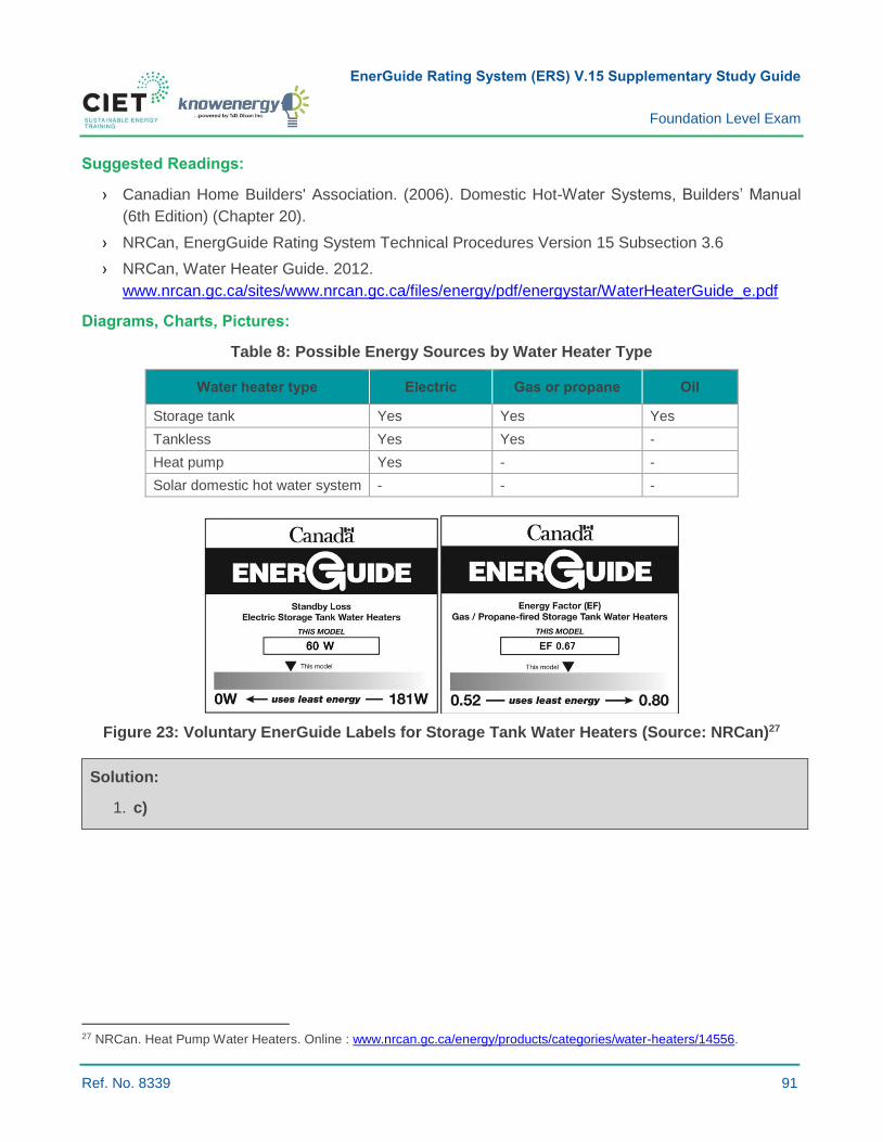
EnerGuide Rating System (ERS) V.15 Supplementary Study Guide
Foundation Level Exam
Ref. No. 8339 91
Suggested Readings:
› Canadian Home Builders' Association. (2006). Domestic Hot-Water Systems, Builders’ Manual
(6th Edition) (Chapter 20).
› NRCan, EnergGuide Rating System Technical Procedures Version 15 Subsection 3.6
› NRCan, Water Heater Guide. 2012.
www.nrcan.gc.ca/sites/www.nrcan.gc.ca/files/energy/pdf/energystar/WaterHeaterGuide_e.pdf
Diagrams, Charts, Pictures:
Table 8: Possible Energy Sources by Water Heater Type
Water heater type Electric Gas or propane Oil
Storage tank Yes Yes Yes
Tankless Yes Yes -
Heat pump Yes - -
Solar domestic hot water system - - -
Figure 23: Voluntary EnerGuide Labels for Storage Tank Water Heaters (Source: NRCan)27
Solution:
1. c)
27 NRCan. Heat Pump Water Heaters. Online : www.nrcan.gc.ca/energy/products/categories/water-heaters/14556.
EnerGuide Rating System (ERS) V.15 Supplementary Study Guide
Foundation Level Exam
Ref. No. 8339 92
6.3.7 IDENTIFY DRAIN WATER HEAT RECOVERY SYSTEMS
Key Concepts: Drain water; heat recovery.
Summary:
› Drain water heat recovery (DWHR) systems use the energy contained in warm water flowing down
the drains to preheat water before it enters the water tank or tankless water heating system.
› Alternatively, DWHRs can preheat cold water flowing to a showerhead.
Drain Water:
All water used inside a residential building ends up in the drain and then into a drain stack (or main
drain pipe).
Drain Water Heat Recovery:
› Drain water heat recovery systems recover the energy contained in warm water flowing down the
drain to preheat cold water before the waste water is disposed to municipal or septic
disposal systems.
› They can also be used in a decentralized manner to preheat cold water flowing to the showerhead.
› DWHR is alternatively called water heat recycling, waste water heat recovery, or greywater
heat recovery.
› Preheating water reduces energy needs for domestic hot water and saves energy or fuel.
› DWHR systems vary in pipe size, configuration, heat exchanger design, cost, and achieved
energy savings.
Drain Water Heat Recovery Systems:
Type 1: Description of copper coils around copper drainpipes:
› Cold water runs through a series of coils wrapped around the drain stack to absorb the thermal
energy of the drain water.
› The assembly, made of copper (including inner tubing), replaces a section of the drain stack.
› DWHR copper coils only work when demand for hot water occurs at the same time as the
generation of drain water.
› DWHR copper coil systems should be installed in a counter flow manner to enhance
heat exchange.
› Where permitted by building codes and regulations, the exchange coil can be installed on the
shower feed to preheat cold water.
› No special maintenance and no moving parts are required.
EnerGuide Rating System (ERS) V.15 Supplementary Study Guide
Foundation Level Exam
Ref. No. 8339 93
Savings from Copper Coils Around Copper Drainpipes:
› Depending on the size, technology and water consumption profile, DWHR systems reduce hot
water requirements for showering by 40 to 60 percent.28
› Efficiency increases with the length of the drain pipe replaced by a DWHR system.
› DWHR systems are cost-effective for households with three or more occupants using mostly the
shower (i.e. not the bath).
Question:
1 Which of the following statements is false?
a) DWHR systems should be installed in a counter flow manner to enhance heat exchange.
b) DWHR systems require a lot of maintenance.
c) DWHR systems work best with simultaneous flows of hot water like showers where there is
demand for hot water while hot water flows down the drain.
d) DWHR systems are used in a decentralized manner, using DWHR to preheat cold water
before it reaches the showerhead.
Suggested Readings:
› NRCan. Energy Efficiency Ratings for drain-water heat recovery products. Online:
oee.nrcan.gc.ca/pml-lmp/index.cfm?action=app.search-recherche&appliance=DWHR.
› Canada Mortgage and Housing Corporation (CMHC), Drain Water Heat Recovery (DWHR).
Online: www.cmhc-schl.gc.ca/en/inpr/su/sufepr/sufepr_003.cfm.
28 Canadian Mortgage and Housing Corporation online: www.cmhc-schl.gc.ca/en/inpr/su/sufepr/sufepr_003.cfm.

EnerGuide Rating System (ERS) V.15 Supplementary Study Guide
Foundation Level Exam
Ref. No. 8339 94
Diagrams, Charts, Pictures:
Figure 24: DHWR Used in a Decentralized Manner to Preheat Cold Water Before Reaching Showerhead (Source: Wikimedia Commons)29
Figure 25: Installation of a Double-walled Copper-on-copper Heat Exchanger in a Vertical Section of the Master Drain Line in a Canadian Home (2007) (Source: Wikimedia Common)30
Solution:
1. b)
29 Image by Ashp uk, Wikimedia Commons. Online: commons.wikimedia.org/wiki/File:Waste_Water_Heat_Recovery_in_the_most_efficient_%27equal_flow%27_configuration.png. 30 Image by Recycle9876, Wikimedia Commons. Online: commons.wikimedia.org/wiki/File:Hot_water_heat_recycling_unit.jpg.
EnerGuide Rating System (ERS) V.15 Supplementary Study Guide
Foundation Level Exam
Ref. No. 8339 95
6.3.12-13 DESCRIBE TYPES OF COMBUSTION AIR SUPPLY AND EXHAUST - IDENTIFY THE TYPES OF VENTING SYSTEMS
Key Concepts: Combustion air; induced, forced, and natural convection exhaust.
Summary:
› Combustion air contains 78 percent oxygen because the latter is necessary for burning fuel such
as gas, oil, and wood. For a furnace/heater to work properly, it must have an adequate supply of
combustion air in accordance with the fuel type use.
› Exhaust gas: The combustion of fuel produces gases called combustion products (e.g. CO2, CO,
NO2). These gases are toxic and are therefore exhausted outside the building.
Naturally Aspirated Combustion Air Supply
› These systems rely on the natural buoyancy of heated flue gases for venting and draw air from
the house for combustion.
› Dilution or combustion air is brought in through a draft hood primarily to isolate the burner from
changing outside pressure conditions at the top of the chimney.
› Naturally aspirated combustion appliance efficiencies are typically around 65 percent.
› These units are prone to flue gas spillage (back-drafting) when other combustion appliances and
exhaust fans are operating.
› Naturally aspirated gas furnaces are typically equipped with a pilot light.
› The primary heat exchanger must operate at high temperature to prevent condensation from
accumulating on the metal parts and to force flue gases up the chimney.
Induced Exhaust:
› The mechanical draft is produced by a fan downstream of the combustion zone.
› Combustion air is drawn from the home and the flue fan forces the combustion gases out through
the flue.
Forced Combustion Air:
› The mechanical draft is produced by a fan upstream of the combustion zone.
› The system supplies air to the burner and forces the hot combustion gases through the heat
exchanger and out of the house through the flue pipe.
EnerGuide Rating System (ERS) V.15 Supplementary Study Guide
Foundation Level Exam
Ref. No. 8339 96
Induced exhaust and forced combustion air have the flowing advantages:
› The furnace resists flue gas spillage (back-drafting) more effectively than naturally aspirated units,
but does not eliminate back-drafting.
› No draft hood is needed.
› Due to a lack of dilution air, less gas flows through the venting system.
› Instead of venting through a roof, the flue often vents through a wall.
› These systems use a pilot light or electronic ignition.
› Efficiency of these systems ranges from 78 to 83 percent.
Sealed Forced Combustion Air and Exhaust (Direct Vent):
› Self-contained sealed combustion heating appliances draw combustion air and discharge
combustion products through a vent to the outside.
› They are permanently attached to the building structure and are not connected to ductwork.
Question:
1 Which of the following systems prevents combustion gas spillage?
a) Naturally aspirated.
b) Forced draft.
c) Induced draft.
d) Direct vent.
Suggested Readings:
› Canada Mortgage and Housing Corporation (CMHC), A Guide to Mechanical Equipment for
Healthy Indoor Environments, page 13.
› Natural Resources Canada (NRCAN).
http://oee.nrcan.gc.ca/residential/personal/oil-forced-air-heating-systems.cfm?attr=4.
Solution:
1. d)

EnerGuide Rating System (ERS) V.15 Supplementary Study Guide
Foundation Level Exam
Ref. No. 8339 97
6.4.2 DESCRIBE DIFFERENT TYPES OF VENTILATION DISTRIBUTION SYSTEMS AND THEIR ADVANTAGES AND LIMITATIONS
Key Concepts: Ventilation distribution systems; exhaust-only ventilation; infiltration; heat recovery
ventilator (HRV); energy recovery ventilator (ERV); passive ventilation.
Summary:
› Distributing air throughout a building usually requires fans and a ducting system, unless passive
or natural ventilation is used.
› A few types of ventilation distribution systems exist, each with their own advantages
and limitations.
› Most building codes require balanced mechanical ventilation that can be integrated to forced-air
heating systems or independently ducted inside homes.
› Passive air ventilation is also used to provide air cooling during the summer season.
Ventilation Systems:
› Ventilation systems are used to provide adequate indoor air quality and humidity inside buildings
and evacuate contaminated and polluted air.
› Ventilation systems in most new residential buildings are required by law and should be installed
according to the National Building Code of Canada (NBC) (Subsection 9.32) and CAN/CSA-F326-
M91, Residential Mechanical Ventilation Systems.
› Additional provisions exist in different Provinces in Canada.
› Codes usually determine the flow rate that should be introduced inside a home based on floor
area, number of occupants, number of bedrooms, number of rooms that require exhaust, or a
combination of these parameters.
› Specific measures should be taken in the case of soil gas, attached garages, and fuel-fired
equipment that is not directly or mechanically vented.
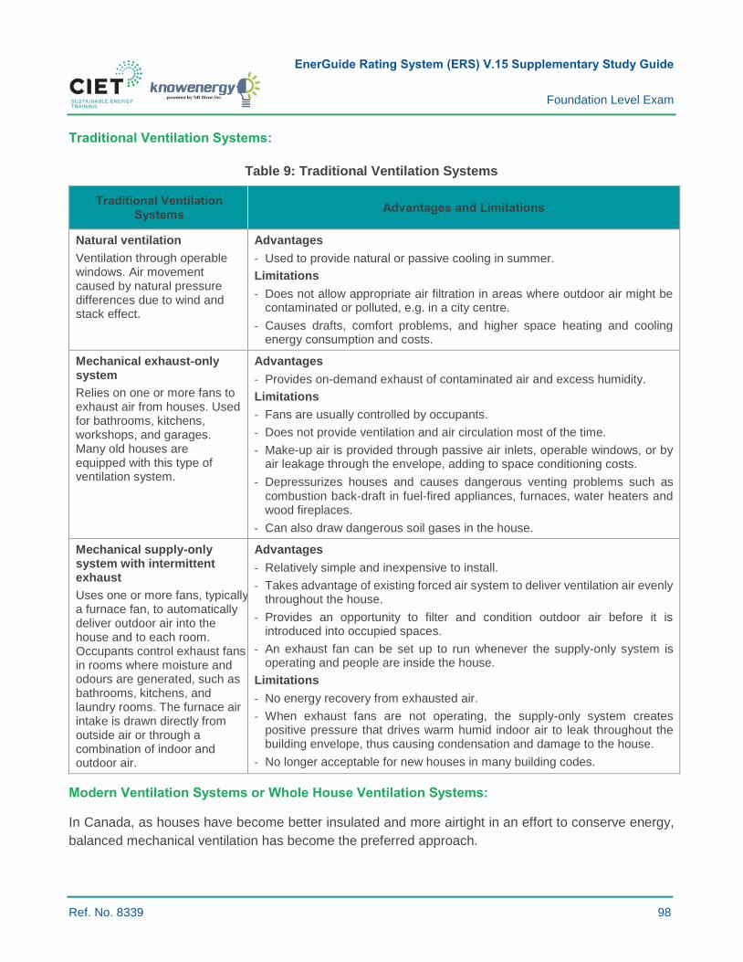
EnerGuide Rating System (ERS) V.15 Supplementary Study Guide
Foundation Level Exam
Ref. No. 8339 98
Traditional Ventilation Systems:
Table 9: Traditional Ventilation Systems
Traditional Ventilation Systems
Advantages and Limitations
Natural ventilation
Ventilation through operable windows. Air movement caused by natural pressure differences due to wind and stack effect.
Advantages
- Used to provide natural or passive cooling in summer.
Limitations
- Does not allow appropriate air filtration in areas where outdoor air might be contaminated or polluted, e.g. in a city centre.
- Causes drafts, comfort problems, and higher space heating and cooling energy consumption and costs.
Mechanical exhaust-only system
Relies on one or more fans to exhaust air from houses. Used for bathrooms, kitchens, workshops, and garages. Many old houses are equipped with this type of ventilation system.
Advantages
- Provides on-demand exhaust of contaminated air and excess humidity.
Limitations
- Fans are usually controlled by occupants.
- Does not provide ventilation and air circulation most of the time.
- Make-up air is provided through passive air inlets, operable windows, or by air leakage through the envelope, adding to space conditioning costs.
- Depressurizes houses and causes dangerous venting problems such as combustion back‐draft in fuel‐fired appliances, furnaces, water heaters and wood fireplaces.
- Can also draw dangerous soil gases in the house.
Mechanical supply-only system with intermittent exhaust
Uses one or more fans, typically a furnace fan, to automatically deliver outdoor air into the house and to each room. Occupants control exhaust fans in rooms where moisture and odours are generated, such as bathrooms, kitchens, and laundry rooms. The furnace air intake is drawn directly from outside air or through a combination of indoor and outdoor air.
Advantages
- Relatively simple and inexpensive to install.
- Takes advantage of existing forced air system to deliver ventilation air evenly throughout the house.
- Provides an opportunity to filter and condition outdoor air before it is introduced into occupied spaces.
- An exhaust fan can be set up to run whenever the supply-only system is operating and people are inside the house.
Limitations
- No energy recovery from exhausted air.
- When exhaust fans are not operating, the supply-only system creates positive pressure that drives warm humid indoor air to leak throughout the building envelope, thus causing condensation and damage to the house.
- No longer acceptable for new houses in many building codes.
Modern Ventilation Systems or Whole House Ventilation Systems:
In Canada, as houses have become better insulated and more airtight in an effort to conserve energy,
balanced mechanical ventilation has become the preferred approach.
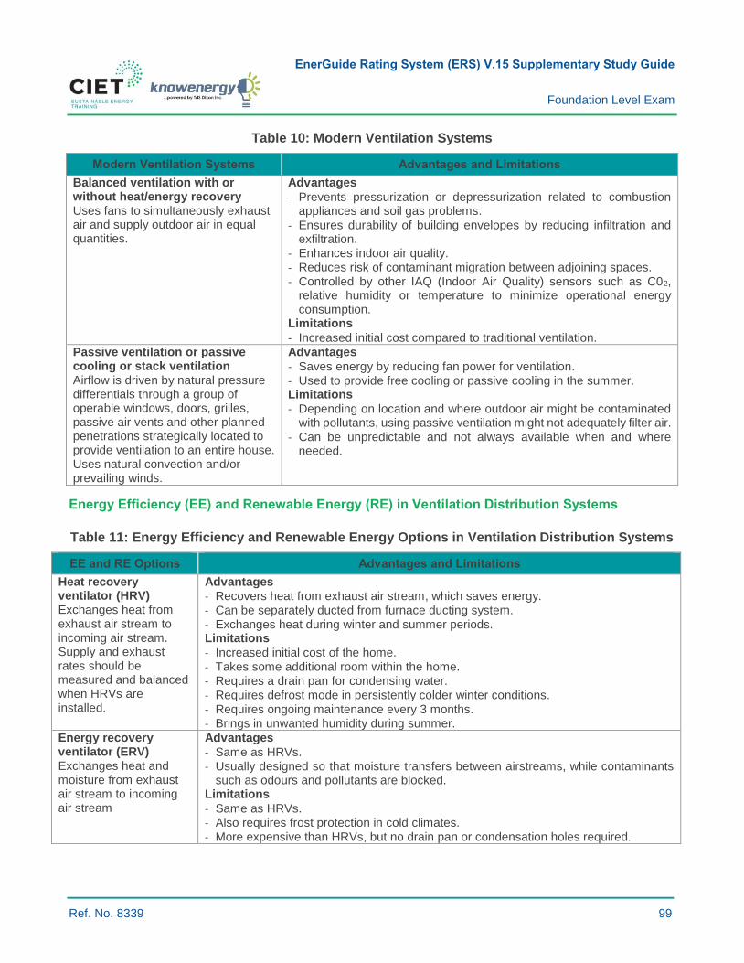
EnerGuide Rating System (ERS) V.15 Supplementary Study Guide
Foundation Level Exam
Ref. No. 8339 99
Table 10: Modern Ventilation Systems
Modern Ventilation Systems Advantages and Limitations
Balanced ventilation with or without heat/energy recovery Uses fans to simultaneously exhaust air and supply outdoor air in equal quantities.
Advantages
- Prevents pressurization or depressurization related to combustion appliances and soil gas problems.
- Ensures durability of building envelopes by reducing infiltration and exfiltration.
- Enhances indoor air quality. - Reduces risk of contaminant migration between adjoining spaces. - Controlled by other IAQ (Indoor Air Quality) sensors such as C02,
relative humidity or temperature to minimize operational energy consumption.
Limitations
- Increased initial cost compared to traditional ventilation.
Passive ventilation or passive cooling or stack ventilation Airflow is driven by natural pressure differentials through a group of operable windows, doors, grilles, passive air vents and other planned penetrations strategically located to provide ventilation to an entire house. Uses natural convection and/or prevailing winds.
Advantages
- Saves energy by reducing fan power for ventilation. - Used to provide free cooling or passive cooling in the summer. Limitations
- Depending on location and where outdoor air might be contaminated with pollutants, using passive ventilation might not adequately filter air.
- Can be unpredictable and not always available when and where needed.
Energy Efficiency (EE) and Renewable Energy (RE) in Ventilation Distribution Systems
Table 11: Energy Efficiency and Renewable Energy Options in Ventilation Distribution Systems
EE and RE Options Advantages and Limitations
Heat recovery ventilator (HRV) Exchanges heat from exhaust air stream to incoming air stream. Supply and exhaust rates should be measured and balanced when HRVs are installed.
Advantages
- Recovers heat from exhaust air stream, which saves energy. - Can be separately ducted from furnace ducting system. - Exchanges heat during winter and summer periods. Limitations
- Increased initial cost of the home. - Takes some additional room within the home. - Requires a drain pan for condensing water. - Requires defrost mode in persistently colder winter conditions. - Requires ongoing maintenance every 3 months. - Brings in unwanted humidity during summer.
Energy recovery ventilator (ERV) Exchanges heat and moisture from exhaust air stream to incoming air stream
Advantages
- Same as HRVs. - Usually designed so that moisture transfers between airstreams, while contaminants
such as odours and pollutants are blocked. Limitations
- Same as HRVs. - Also requires frost protection in cold climates. - More expensive than HRVs, but no drain pan or condensation holes required.

EnerGuide Rating System (ERS) V.15 Supplementary Study Guide
Foundation Level Exam
Ref. No. 8339 100
EE and RE Options Advantages and Limitations
Control of HRVs and ERVs HRVs and ERVs are usually controlled by a central wall controller and additional control units in exhaust system
Advantages
- Allows reducing the flow rate of HRVs/ERVs when exhausting air is not required, e.g. when the house is unoccupied.
- Allows for intermittent use of HRVs or ERVs, such as 20 minutes every hour. - Allows for better control of humidity levels and reduces energy use. - Can be combined with CO2 sensors to introduce proper amount of ventilation inside the
home. Limitations
- Control is more efficient if HRVs or ERVs are separately ducted from heating systems. - Advanced initial setup and homeowner education is required,
Ground-coupled heat exchanger (earth-air heat exchangers or earth tubes) Preheats air using underground tubes prior to sending air to HRVs or ERVs.
Advantages
- Less costly for new constructions where soil has to be removed to install home drains and foundations.
- Works for both heating air in winter and cooling air in summer. Limitations
- Increased initial cost. - Requires space around the home (not ideal in densely constructed areas). - Caution should be taken where soil gases is an issue. - A high level of detail is required for design and installation to prevent moisture related
issues such as mould in the tubes.
Solar air heating system Heat supplied to air using solar heating collectors prior or after (ideally after) sending air to HRVs or ERVs.
Advantages
- Lowers energy requirements during daytime in winter. - Used with HRVs or ERVs, but with limited combined efficiency if outdoor air passes
through solar collector prior to the heat exchanger (outdoor air should pass through the heat exchanger prior to entering the solar panel for increased efficiency).
- Can also be combined with a ground-coupled heat exchanger. Limitations
- Only useful in winter. - Needs some sort of bypass mechanism and control to use solar panels only when
needed.
- Increased initial cost of the home. - Requires a south-facing wall or angled roof. - Variable output.
Ventilation Distribution Systems:
› Air distribution throughout a building usually requires fans and associated ductwork, grilles,
diffusers, and vents unless passive (or natural) ventilation is used.
› Without distribution, fresh air might not reach all rooms in a house and cause pockets of stale or
moist air.
› Ventilation air is usually distributed to rooms where occupants spend more time, including
bedrooms, kitchens, living and dining rooms, etc.
› A ventilation system should be capable of circulating air within rooms or delivering air evenly within
occupied spaces.
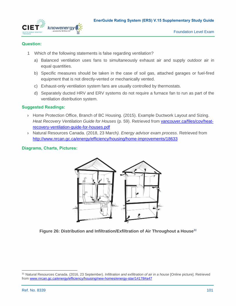
EnerGuide Rating System (ERS) V.15 Supplementary Study Guide
Foundation Level Exam
Ref. No. 8339 101
Question:
1 Which of the following statements is false regarding ventilation?
a) Balanced ventilation uses fans to simultaneously exhaust air and supply outdoor air in
equal quantities.
b) Specific measures should be taken in the case of soil gas, attached garages or fuel-fired
equipment that is not directly-vented or mechanically vented.
c) Exhaust-only ventilation system fans are usually controlled by thermostats.
d) Separately ducted HRV and ERV systems do not require a furnace fan to run as part of the
ventilation distribution system.
Suggested Readings:
› Home Protection Office, Branch of BC Housing. (2015). Example Ductwork Layout and Sizing.
Heat Recovery Ventilation Guide for Houses (p. 59). Retrieved from vancouver.ca/files/cov/heat-
recovery-ventilation-guide-for-houses.pdf
› Natural Resources Canada. (2018, 23 March). Energy advisor exam process. Retrieved from
http://www.nrcan.gc.ca/energy/efficiency/housing/home-improvements/18633
Diagrams, Charts, Pictures:
Figure 26: Distribution and Infiltration/Exfiltration of Air Throughout a House31
31 Natural Resources Canada. (2016, 23 September). Infiltration and exfiltration of air in a house [Online picture]. Retrieved from www.nrcan.gc.ca/energy/efficiency/housing/new-homes/energy-star/14178#a47
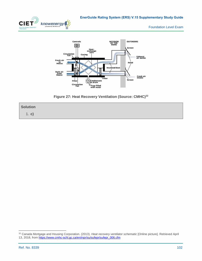
EnerGuide Rating System (ERS) V.15 Supplementary Study Guide
Foundation Level Exam
Ref. No. 8339 102
Figure 27: Heat Recovery Ventilation (Source: CMHC)32
Solution
1. c)
32 Canada Mortgage and Housing Corporation. (2013). Heat recovery ventilator schematic [Online picture]. Retrieved April 13, 2018, from https://www.cmhc-schl.gc.ca/en/inpr/su/sufepr/sufepr_006.cfm
EnerGuide Rating System (ERS) V.15 Supplementary Study Guide
Foundation Level Exam
Ref. No. 8339 103
6.4.6 DESCRIBE BALANCED VENTILATION WITH AND WITHOUT HEAT RECOVERY
Key Concepts: Balanced ventilation; heat recovery ventilators (HRVs); energy recovery
ventilators (ERVs).
Summary:
› Balanced mechanical ventilation systems use supply and exhaust fans to simultaneously exhaust
stale air and supply outdoor air in equal quantities. It is the preferred and in many jurisdictions the
only allowed approach to ventilation.
› Balanced ventilation with heat recovery ensures better control of the quantity and quality of air
being exchanged. It also maintains a neutral pressure plane inside the house, thus mitigating
pressure differences (and associated transport of unconditioned air, soil gases, moisture, etc.)
across the building envelope and tempers incoming supply air to reduce the heating load.
Ventilation Systems:
› Every ventilation system should strive toward a balance between supply and exhaust airflow to
prevent pressurization or depressurization.
› Ventilation systems are configured as:
- A balanced system (both supply and demand);
- Supply only (not permitted in most jurisdictions);
- Exhaust only (not permitted in some jurisdictions).
› The design, fabrication, and installation of ventilation systems are guided by best practices and
building code requirements that vary between jurisdictions.
Balanced Ventilation:
› Balanced ventilation systems are designed with the objective of maintaining neutral pressure
inside buildings by providing fresh outdoor air at the same rate as exhaust air. This results in little
pressure difference across the envelope.
› A large pressure difference across a building envelope can lead to undesired infiltration or
exfiltration of air, with possible condensation problems within building walls.
› Making a house more airtight also helps maintain a smaller pressure difference across
the envelope.

EnerGuide Rating System (ERS) V.15 Supplementary Study Guide
Foundation Level Exam
Ref. No. 8339 104
Heat and Moisture Recovery:
› Balanced ventilation systems allow heat exchange from the exhaust air stream to the incoming air
stream through a heat recovery ventilator (HRV) or energy recovery ventilator (ERV), thereby
reducing the cost of tempering the fresh air supply during cold weather.
› ERVs recover sensible and latent (moisture) heat in winter and help dehumidify the air supply
in summer.
› ERVs transfer a portion of the moisture from more humid air flow (indoor air in winter and outdoor
air in summer) to drier air flow, thus helping to regulate humidity levels in the house.
› HRVs and ERVs are designed for specific climate conditions and should be selected accordingly.
› Some equipment might require a defrost mechanism.
› HRVs should be installed with a condensate drain, whereas properly designed ERVs transfer the
majority of moisture and do not require a condensate drain for the defrost cycle.
› Subsection 9.36 of the NBC prescribes minimum performance requirements if an HRV/ERV
is used.
› HRV/ERV equipment should be selected based on its ability to meet the ventilation requirements
of the home, heat recovery efficiency, defrost mechanism, product availability, availability of
installers/service providers, and installation costs.
› Unbalanced ventilation systems reduce the efficiency of HRVs or ERVs.
Sensible Recovery Efficiency (SRE):
› SRE is used to calculate the energy efficiency of HRVs and ERVs. Factory-assembled packaged
units include fans or blowers that transfer heat between two isolated airstreams.
› SRE is the net sensible energy recovered by the supply airstream. SRE takes into consideration
electrical consumption, case heat loss or heat gain, air leakage, airflow mass imbalance between
the two airstreams, and the energy for frost control.
› SRE is usually specified in Canada for temperatures of 0°C (32°F) and -25°C (-13°F).
› HRVs and ERVs typically have efficiency of 50 to 84 percent according to outdoor temperatures
and flow rates.
EnerGuide Rating System (ERS) V.15 Supplementary Study Guide
Foundation Level Exam
Ref. No. 8339 105
Total Recovery Efficiency (TRE):
› Energy recovery ventilators (ERVs) are designed to transfer both heat and moisture. The total
recovery efficiency (TRE) is used to measure the overall energy performance of ERVs.
› The TRE is equivalent to the ratio of total (sensible + latent) energy transferred between the two
airstreams compared to the total energy transported through the heat exchanger. It corrects for
the effects of cross-leakage, purchased energy for fan and controls, as well as defrost systems.
Maintaining HRVs/ERVs:
› HRVs and ERVs should be serviced every year and kept clean to operate efficiently.
› Air filters should be cleaned or replaced every one to three months.
Question:
1 Which of the following statements is false?
a) Building code requirements for the design, fabrication, and installation of mechanical
ventilation systems vary by province.
b) SRE measures the net sensible energy recovered by the supply airstream, excluding
latent energy.
c) Heat recovery ventilators (HRVs) are designed to transfer both heat and moisture.
d) Balanced ventilation systems are designed with the objective of maintaining neutral pressure
inside buildings.
Suggested Readings:
› Canada Mortgage and Housing Corporation. (2013). Heat recovery ventilator. Retrieved April 13,
2018, from https://www.cmhc-schl.gc.ca/en/inpr/su/sufepr/sufepr_006.cfm
› Canada Mortgage and Housing Corporation. (2018). Maintaining Your Heat Recovery Ventilator.
Retrieved April 13, 2018, from www.cmhc-schl.gc.ca/en/co/grho/grho_003.cfm
› Natural Resources Canada. (2012). HRV maintenance chart. Heat Recovery Ventilators (p. 26).
Retrieved from www.nrcan.gc.ca/sites/www.nrcan.gc.ca/files/energy/pdf/energystar/HRV_EN.pdf
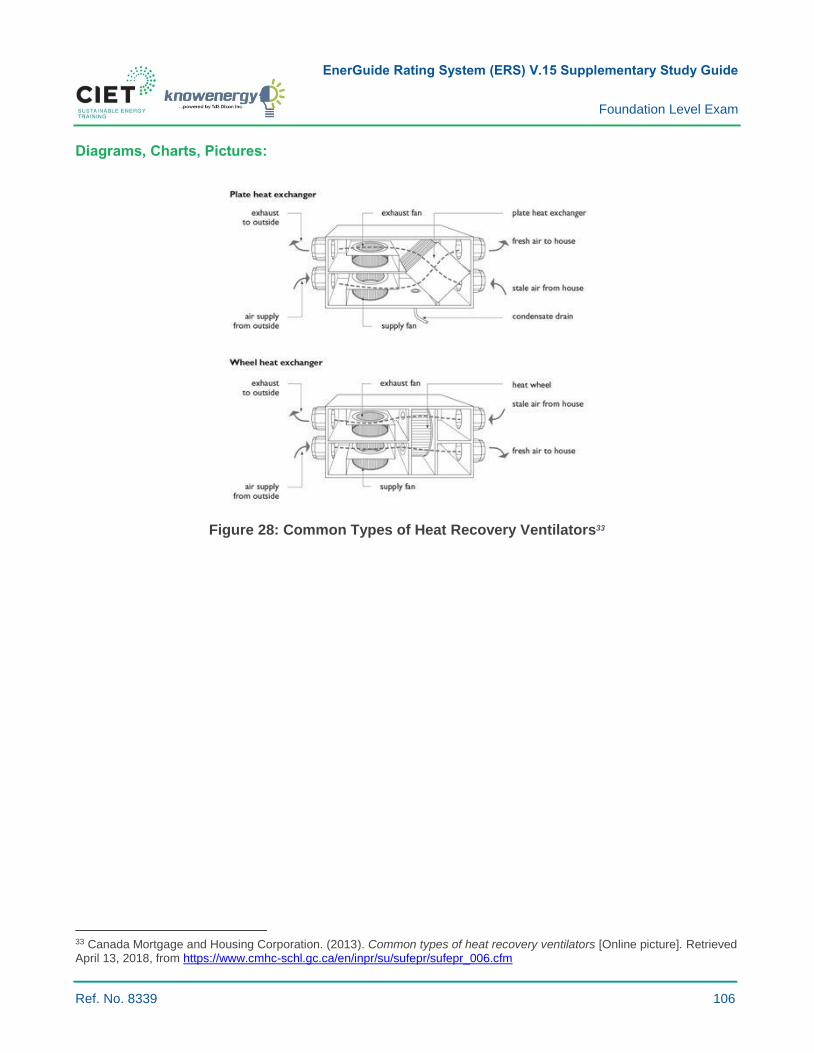
EnerGuide Rating System (ERS) V.15 Supplementary Study Guide
Foundation Level Exam
Ref. No. 8339 106
Diagrams, Charts, Pictures:
Figure 28: Common Types of Heat Recovery Ventilators33
33 Canada Mortgage and Housing Corporation. (2013). Common types of heat recovery ventilators [Online picture]. Retrieved April 13, 2018, from https://www.cmhc-schl.gc.ca/en/inpr/su/sufepr/sufepr_006.cfm

EnerGuide Rating System (ERS) V.15 Supplementary Study Guide
Foundation Level Exam
Ref. No. 8339 107
Figure 29: Balanced Ventilation System with HRV34
Solution:
1. c)
34Natural Resources Canada. (2009, 26 September). Heat Recovery Ventilator (HRV) (not connected to a forced-air heating system [Online picture]). Retrieved from oee.nrcan.gc.ca/residential/personal/new-homes/r-2000/standard/whole-house-
ventilation.cfm?attr=12

EnerGuide Rating System (ERS) V.15 Supplementary Study Guide
Foundation Level Exam
Ref. No. 8339 108
6.7.1 DESCRIBE THE FUNDAMENTAL PRINCIPLES IN PASSIVE SOLAR DESIGN
Key Concepts: Passive solar design; home orientation; glazing.
Summary:
Passive solar design effectively incorporates site selection, building orientation, solar gains,
shading/windbreak, landscaping, building materials and airtightness. It also lowers heating costs and
increases occupant comfort; however, designers must consider factors that contribute to overheating
and increased cooling loads.
Passive Solar Energy:
› Passive solar energy enters a house through:
- The glazed portions of windows and doors;
- Heat transmitted through building assemblies.
› The contribution of solar energy to heating needs:
- Varies due to local weather conditions, building heating requirements, as well as the size,
orientation, shading and type of window glazing units;
- Usually provides 15 percent of an average home’s heating through solar heat, but this
percentage significantly increases when homes are designed and built to maximize solar
heat gains.
Key Design Principles:
› Orientation:
- To optimize energy efficiency, building sites should have good solar exposure;
- Orient homes on sites that let in sunlight during spring.
› Trees and shrubs:
- Locate deciduous trees and shrubs to provide summer shade to east, west, and
south-facing glazing;
- Landscaping with coniferous trees along the north-west face may further shield the structure
from cold winter winds without blocking winter sun.
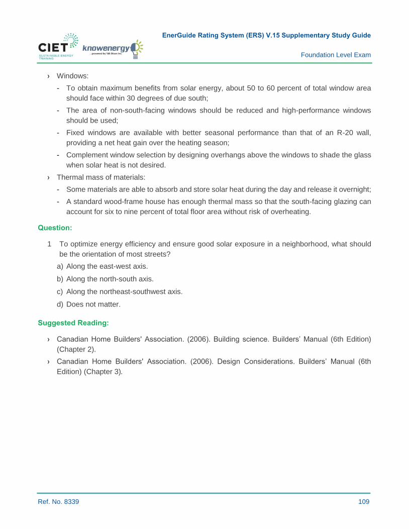
EnerGuide Rating System (ERS) V.15 Supplementary Study Guide
Foundation Level Exam
Ref. No. 8339 109
› Windows:
- To obtain maximum benefits from solar energy, about 50 to 60 percent of total window area
should face within 30 degrees of due south;
- The area of non-south-facing windows should be reduced and high-performance windows
should be used;
- Fixed windows are available with better seasonal performance than that of an R-20 wall,
providing a net heat gain over the heating season;
- Complement window selection by designing overhangs above the windows to shade the glass
when solar heat is not desired.
› Thermal mass of materials:
- Some materials are able to absorb and store solar heat during the day and release it overnight;
- A standard wood-frame house has enough thermal mass so that the south-facing glazing can
account for six to nine percent of total floor area without risk of overheating.
Question:
1 To optimize energy efficiency and ensure good solar exposure in a neighborhood, what should
be the orientation of most streets?
a) Along the east-west axis.
b) Along the north-south axis.
c) Along the northeast-southwest axis.
d) Does not matter.
Suggested Reading:
› Canadian Home Builders' Association. (2006). Building science. Builders’ Manual (6th Edition)
(Chapter 2).
› Canadian Home Builders' Association. (2006). Design Considerations. Builders’ Manual (6th
Edition) (Chapter 3).

EnerGuide Rating System (ERS) V.15 Supplementary Study Guide
Foundation Level Exam
Ref. No. 8339 110
Diagrams, Charts, and Pictures:
Figure 30: Optimal Home Orientation in Passive Solar Design35
Figure 31: Winter and Summer Shading36
35 Canadian Home Builders' Association. (2006). Optimal Home Orientation in Passive Solar Design. Builders’ Manual (6th
Edition) (p. 37). 36 Canadian Home Builders' Association. (2006). Winter and Summer Shading. Builders’ Manual (6th Edition) (p. 37).
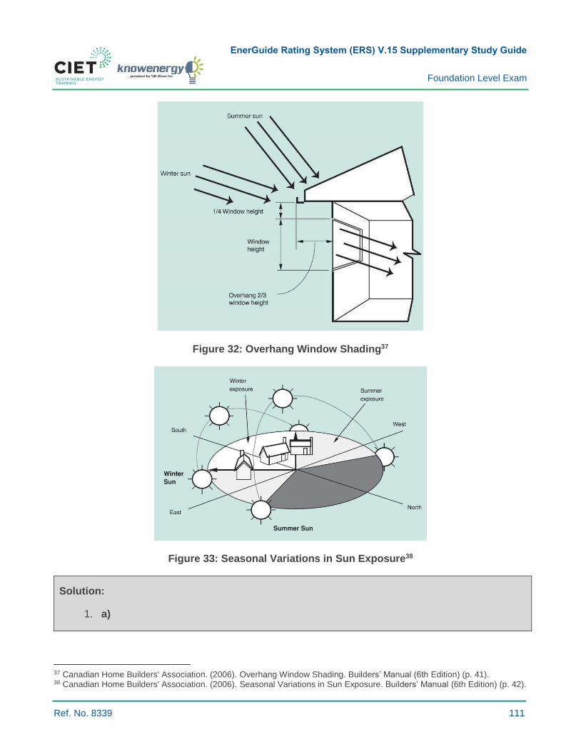
EnerGuide Rating System (ERS) V.15 Supplementary Study Guide
Foundation Level Exam
Ref. No. 8339 111
Figure 32: Overhang Window Shading37
Figure 33: Seasonal Variations in Sun Exposure38
Solution:
1. a)
37 Canadian Home Builders' Association. (2006). Overhang Window Shading. Builders’ Manual (6th Edition) (p. 41). 38 Canadian Home Builders' Association. (2006). Seasonal Variations in Sun Exposure. Builders’ Manual (6th Edition) (p. 42).

EnerGuide Rating System (ERS) V.15 Supplementary Study Guide
Foundation Level Exam
Ref. No. 8339 112
6.7.6 DESCRIBE THE GENERAL PRINCIPLES OF ACTIVE SOLAR DOMESTIC WATER HEATING
Key Concepts: Solar domestic hot water (SDHW); collectors; circulation systems; active vs. passive
SDHW; solar-ready buildings.
Summary:
› Solar domestic hot water (SDHW) systems consist of solar collectors that directly or indirectly heat
domestic water with an antifreeze fluid such as propylene glycol.
› These systems are active (using a circulating pump) or passive (not using a circulating pump);
active systems are more common in Canada.
Active vs. Passive Solar Domestic Water Heating:
› Active systems:
- Use electric pumps, valves and controllers to move heated water, or antifreeze fluid such as
propylene glycol, throughout the system from solar collectors to a storage tank;
- These are the most common systems in Canada.
› Passive systems:
- Require no pump and use natural convection moving water from collectors to a storage tank;
- Also operate with main water pressure;
- Passive SDHW is used in warmer climates and rarely found in Canada.
Active Solar Domestic Water Heating:
› Different types of SDHW systems are available.
› Systems usually include solar collectors, controls, plumbing, pumps, and water heaters.
› They usually require maintenance and repair because they are more complex and contain several
components that require regular maintenance (i.e. pump, probe, and control board).
› In Canada, it is important to pick a system that is protected from freezing for year-round water
heating, usually using an antifreeze fluid such as propylene glycol in the collectors instead
of water.
› Systems still generate heat even if outside temperature is well below zero.
› In Canada, SDHW systems provide up to 40 to 60 percent of the hot water for an average home,
depending on local climate, the size of panel system installed, typical hot water use,39 and number
of occupants in the home.
39 Natural Resources Canada. (2017, 17 October). Solar Water Heaters. Retrieved from
www.nrcan.gc.ca/energy/products/categories/water-heaters/14562
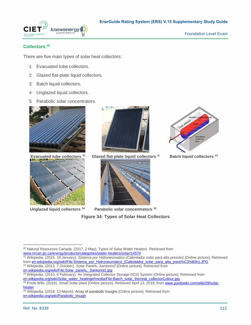
EnerGuide Rating System (ERS) V.15 Supplementary Study Guide
Foundation Level Exam
Ref. No. 8339 113
Collectors:40
There are five main types of solar heat collectors:
1 Evacuated tube collectors.
2 Glazed flat-plate liquid collectors.
3 Batch liquid collectors.
4 Unglazed liquid collectors.
5 Parabolic solar concentrators.
Evacuated tube collectors 41 Glazed flat-plate liquid collectors 42 Batch liquid collectors 43
Unglazed liquid collectors 44 Parabolic solar concentrators 45
Figure 34: Types of Solar Heat Collectors
40 Natural Resources Canada. (2017, 2 May). Types of Solar Water Heaters. Retrieved from www.nrcan.gc.ca/energy/products/categories/water-heaters/solar/14570 41 Wikipedia. (2015, 19 January). Sistema por Hidroneumatico (Calentador solar para alta presión) [Online picture]. Retrieved from en.wikipedia.org/wiki/File:Sistema_por_Hidroneumatico_(Calentador_solar_para_alta_presi%C3%B3n).JPG 42 Wikipedia. (2013, 7 October). Solar Panels, Santorini2 [Online picture]. Retrieved from en.wikipedia.org/wiki/File:Solar_panels,_Santorini2.jpg 43 Wikipedia. (2010, 6 February). An Integrated Collector Storage (ICS) System [Online picture]. Retrieved from en.wikipedia.org/wiki/Solar_water_heating#/media/File:Batch_solar_thermal_collectorColour.jpg 44 Pools Wiki. (2016). Small Solar plant [Online picture]. Retrieved April 13, 2018, from www.poolswiki.com/wiki/29/solar-heater 45 Wikipedia. (2018, 13 March). Array of parabolic troughs [Online picture]. Retrieved from en.wikipedia.org/wiki/Parabolic_trough
EnerGuide Rating System (ERS) V.15 Supplementary Study Guide
Foundation Level Exam
Ref. No. 8339 114
Circulation Systems:
› Closed-loop or indirect systems:
- Use a non-freezing liquid (antifreeze) to transfer heat from solar collectors to water using a heat
exchanger installed inside or outside the storage tank;
- Usually used in freezing climates.
› Direct systems:
- Water circulates through solar collectors and water is stored in a tank, sent to a tankless water
heater, or used directly;
- Freeze protection is necessary in cold climates.
› Thermosiphon:
- Uses the changing density of water according to temperatures to circulate water in
solar collectors.
Other Equipment:
› Solar preheat tank:
- An additional tank stores heated water, which connects to a conventional water heater or a
tankless water heater.
› Solar-ready means providing several elements that allow for future installation of SDHW at a lower
cost (storage, piping, connections, extra room in a mechanical room, controls, etc.).
Energy Savings Calculation:
› The efficiency of solar thermal collectors greatly varies with outdoor temperatures and
wind velocity.
› Software like RETScreen is used to estimate energy savings for different types of collectors and
considers a building’s location and such parameters as wind and outside temperature variations
throughout the year.
Question:
1 Which of the following statements is false?
a) An active solar domestic hot water system uses a circulating pump to move water or antifreeze
fluid into solar collectors.
b) Batch liquid collectors heat water in dark tanks or tubes within an insulated box, storing water
until drawn.
c) Passive solar domestic hot water systems are most commonly used in Canada.
d) Evacuated tube liquid collectors are more efficient than glazed flat-plate liquid collectors.

EnerGuide Rating System (ERS) V.15 Supplementary Study Guide
Foundation Level Exam
Ref. No. 8339 115
Suggested Readings:
› Natural Resources Canada. (2003). Solar Water Heating Systems, a Buyer’s Guide. Retrieved
from http://www.nrcan.gc.ca/sites/www.nrcan.gc.ca/files/canmetenergy/files/pubs/SOLAR-
BuyersGuide-SolarWaterHeatingSystems_ENG.pdf
› Natural Resources Canada. (2013). Solar Ready Guidelines. 2013. Retrieved from
www.nrcan.gc.ca/sites/www.nrcan.gc.ca/files/canmetenergy/files/pubs/SolarReadyGuidelines_e
n.pdf
› Canadian Standards Association. (2013). Packaged Solar Domestic Hot Water Systems (liquid-
to-liquid heat transfer). Retrieved from shop.csa.ca/en/canada/renewable-thermal-
energy/cancsa-f379-series-09-r2013/invt/27029412009
› Natural Resources Canada. (2014, 2 May). Types of Solar Water Heaters. Retrieved from
www.nrcan.gc.ca/energy/products/categories/water-heaters/solar/14570
› Natural Resources Canada. (2012). Water Heater Guide, Retrieved from
hwww.nrcan.gc.ca/sites/oee.nrcan.gc.ca/files/files/pdf/equipment/WaterHeaterGuide_e.pdf
› Natural Resources Canada. (2015, 16 December). Performance Directory of Solar Domestic Hot
Water Systems. Retrieved from www.nrcan.gc.ca/energy/renewable-electricity/solar-
thermal/7337
› The Canadian Solar Industries Association (CanSia). National trade association that represents
the solar energy industry. Retrieved from www.cansia.ca/
› Energy Star Certified Models. Find and compare products. Retrieved from:
www.energystar.gov/productfinder/product/certified-water-
heaters/results?SetLanguage=English&NRCAN=on
› North American Board of Certified Energy Practitioners (NABCEP). (2013). Solar Heating Installer
Resource Guide. Retrieved from www.nabcep.org/wp-content/uploads/2013/08/NABCEP-SH-
Guide-8-5-13.pdf
Solution:
1. c)

EnerGuide Rating System (ERS) V.15 Supplementary Study Guide
Foundation Level Exam
Ref. No. 8339 116
6.7.9 INTERPRET APPLICABLE DATA ON THE ENERGY PERFORMANCE OF RENEWABLE ENERGY SYSTEMS
Key Concepts: Energy performance; renewable energy; azimuth; true north; magnetic field; solar
radiation; solar tracking; solar panel orientation; solar photovoltaic (PV) systems; wind energy systems;
batteries; solar water heating systems.
Summary:
› Several data parameters are used to measure or estimate the energy performance of renewable
energy systems (e.g. solar panel efficiency).
› These parameters are used in software like RETScreen or HOT2000 to estimate the energy
delivery of renewable energy systems.
› These parameters are also used by testing agencies, such as CSA, to measure the efficiency of
manufacturers’ renewable energy products.
› Energy produced using renewables reduces the use of other energy sources. Energy saving
calculations should include site energy plus losses in generation, transmission, and distribution,
i.e. supply energy or primary energy.
Decentralized or On-site Renewable Energy Production:
Under the EnerGuide rating system, only decentralized or on-site renewable energy production systems
are considered, including domestic hot water systems and electricity generating systems such as solar
photovoltaic (PV) and wind energy systems.
Solar Systems:
› Solar irradiance and solar radiation:
- Solar irradiance and annual solar radiation are important data in estimating the energy
performance of solar renewable energy systems. These data depend on the location of the
building, altitude and months of the year.
› Solar tracking and solar panel orientation:
- Solar tracking devices are used in both solar PV systems and solar domestic hot
water systems;
- Solar panel orientation determines how much solar radiation is received by the panel.
System Performance:
The following data are used determine PV system efficiency. These values are used in RETScreen to
determine the electricity contribution of PV systems.

EnerGuide Rating System (ERS) V.15 Supplementary Study Guide
Foundation Level Exam
Ref. No. 8339 117
Table 12: Data for Solar PV Projects (Source: RETScreen)
Solar PV Systems
Applicable Data and Definitions
Location – Location of the system to determine solar radiation.
Orientation – Orientation of the panels to true north (axis of Earth’s rotation) should be used as opposed to magnetic north (to which compasses point).
Slope (0° to 90°) – The Angle between the solar collector and the ground:
› Most efficient all year: Latitude of site.
› Most efficient in summer: Latitude of site minus 15°.
› Most efficient in winter: Latitude of site plus 15° (also best against snow accumulation).
Array area (m2 or ft.2) - Sum of the area of each solar panel.
Module efficiency - Indicates how efficiently a solar module converts solar radiation into electrical energy.
Miscellaneous array losses (%) – Power conditioning losses and other losses if any, e.g. DC-DC converter, step-up transformers, or losses due to dirt or snow on the modules.
Inverter efficiency (%) – Used to transform DC output to AC.
Inverter capacity (kW) - Value based on power capacity and inverter efficiency.
Capacity factor (%) - Represents the ratio of the average power produced by a solar panel over a year to its rated power capacity.
Miscellaneous losses (%) - The user enters power conditioning losses (%), if any, not taken into account elsewhere. For example, this can include losses incurred in DC-AC converters or step-up transformers.
Wind Energy Systems:
The following data are used to determine wind energy system efficiency.
Table 13: Data for Wind Energy Projects (Source: RETScreen)
Wind Energy Systems
Applicable Data and Definitions
Location – Used to determine wind profile over a year. The closest weather station is used.
Wind speed (m/s) Range of wind speeds for a given height and location. Used with power curve data for a given wind turbine (power as a function of wind speed).
Air temperature (°C or °F) – Average annual temperature or average monthly temperature.
Atmospheric pressure (kPa or PSI) – Average annual atmospheric pressure or average monthly atmospheric pressure.
Power capacity per unit (kW) – Wind turbine rated power or capacity which is reached at the rated wind speed.
Number of units - Quantity of units installed.
Hub height – Height at which the centre of the rotor is installed. Increasing hub height usually improves project
energy output.
Rotor diameter per turbine - Diameter of the circle formed by blade rotation.
Power curve data - Provides the power output of a wind turbine as a function of wind speed.
Losses – Airfoil losses and other miscellaneous losses.
Capacity factor – Ratio of the average power produced by a wind turbine over a year to its rated power capacity
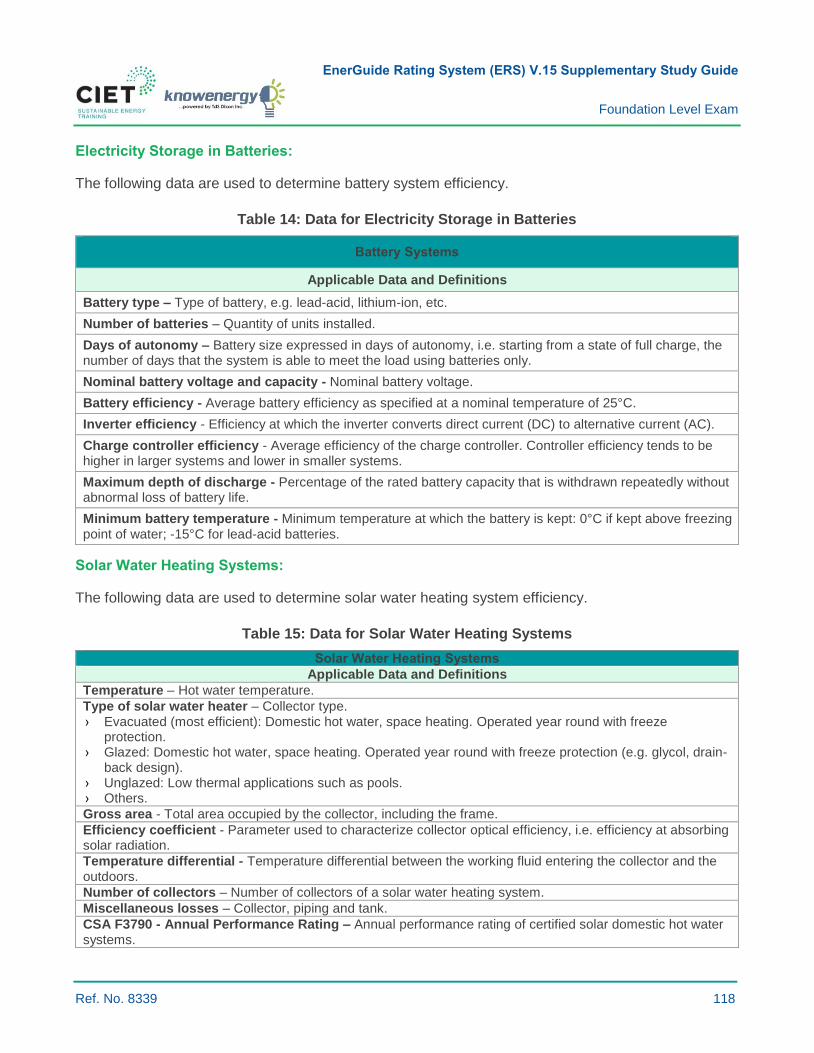
EnerGuide Rating System (ERS) V.15 Supplementary Study Guide
Foundation Level Exam
Ref. No. 8339 118
Electricity Storage in Batteries:
The following data are used to determine battery system efficiency.
Table 14: Data for Electricity Storage in Batteries
Battery Systems
Applicable Data and Definitions
Battery type – Type of battery, e.g. lead-acid, lithium-ion, etc.
Number of batteries – Quantity of units installed.
Days of autonomy – Battery size expressed in days of autonomy, i.e. starting from a state of full charge, the number of days that the system is able to meet the load using batteries only.
Nominal battery voltage and capacity - Nominal battery voltage.
Battery efficiency - Average battery efficiency as specified at a nominal temperature of 25°C.
Inverter efficiency - Efficiency at which the inverter converts direct current (DC) to alternative current (AC).
Charge controller efficiency - Average efficiency of the charge controller. Controller efficiency tends to be higher in larger systems and lower in smaller systems.
Maximum depth of discharge - Percentage of the rated battery capacity that is withdrawn repeatedly without abnormal loss of battery life.
Minimum battery temperature - Minimum temperature at which the battery is kept: 0°C if kept above freezing point of water; -15°C for lead-acid batteries.
Solar Water Heating Systems:
The following data are used to determine solar water heating system efficiency.
Table 15: Data for Solar Water Heating Systems
Solar Water Heating Systems
Applicable Data and Definitions
Temperature – Hot water temperature.
Type of solar water heater – Collector type. › Evacuated (most efficient): Domestic hot water, space heating. Operated year round with freeze
protection. › Glazed: Domestic hot water, space heating. Operated year round with freeze protection (e.g. glycol, drain-
back design). › Unglazed: Low thermal applications such as pools. › Others.
Gross area - Total area occupied by the collector, including the frame.
Efficiency coefficient - Parameter used to characterize collector optical efficiency, i.e. efficiency at absorbing solar radiation.
Temperature differential - Temperature differential between the working fluid entering the collector and the outdoors.
Number of collectors – Number of collectors of a solar water heating system.
Miscellaneous losses – Collector, piping and tank.
CSA F3790 - Annual Performance Rating – Annual performance rating of certified solar domestic hot water systems.
EnerGuide Rating System (ERS) V.15 Supplementary Study Guide
Foundation Level Exam
Ref. No. 8339 119
Question:
1 Which of the following statements is true?
a) A compass points to magnetic north which is located at the axis of Earth’s rotation.
b) A solar photovoltaic panel collects more energy throughout a year if oriented at an angle
corresponding to the latitude of the site.
c) Solar irradiance is the same at sea level as it is at high altitudes.
d) Increasing the height of a wind turbine will usually not affect its energy contribution.
Suggested Readings:
› Natural Resources Canada. (2018, 25 January). RETScreen Expert [User Manual]. Retrieved from
www.nrcan.gc.ca/energy/software-tools/7465
› Natural Resources Canada. (2017, 24 February). Magnetic declination calculator. Retrieved from
www.geomag.nrcan.gc.ca/calc/mdcal-en.php
› Canadian Mortgage and Housing Corporation. (2010). Photovoltaic (PV) Systems. Retrieved from
www.cmhc-schl.gc.ca/en/co/grho/grho_009.cfm
› Canadian Standards Association. (2013). Packaged Solar Domestic Hot Water Systems (liquid-
to-liquid heat transfer). Retrieved from shop.csa.ca/en/canada/renewable-thermal-
energy/cancsa-f379-series-09-r2013/invt/27029412009
› Natural Resources Canada. (2015, 16 December). Performance Directory of Solar Domestic Hot
Water Systems. Retrieved from www.nrcan.gc.ca/energy/renewable-electricity/solar-
thermal/7337
Solution:
1. b)

EnerGuide Rating System (ERS) V.15 Supplementary Study Guide
Foundation Level Exam
Ref. No. 8339 120
7.2.19 DESCRIBE THE PROCEDURE TO DETERMINE THE THERMAL RESISTANCE VALUES OF ASSEMBLIES
Key Concepts: Effective R-value; series vs parallel heat transmission.
Summary:
› The overall wall U-factor or effective R-value is calculated by taking into consideration all
components in the wall that have a significant R-value.
› The R-effective value is detailed in Learning Objective 3.2.3.
› Transmission heat losses through the envelope using the R-effective is detailed in Learning
Objective 6.1.3.
Assembly Thermal Resistance or Heat Transfer Coefficient:
The heat transfer coefficient U [W/m²·°C] of walls is calculated using the sum of material R-values
(m²·°C/W), including insulation caused by indoor and outdoor films of air.
𝑈 [𝑊
m² · °𝐶] =
1
𝑅𝑒𝑓𝑓𝑒𝑐𝑡𝑖𝑣𝑒 [m² · °𝐶
𝑊 ]
For components in series (e.g. insulation and plasterboard):
R1 R2 R3
Heat flow
𝑅𝑒𝑓𝑓𝑒𝑐𝑡𝑖𝑣𝑒−𝑠𝑒𝑟𝑖𝑒𝑠 = 𝑅1 + 𝑅2 + 𝑅3
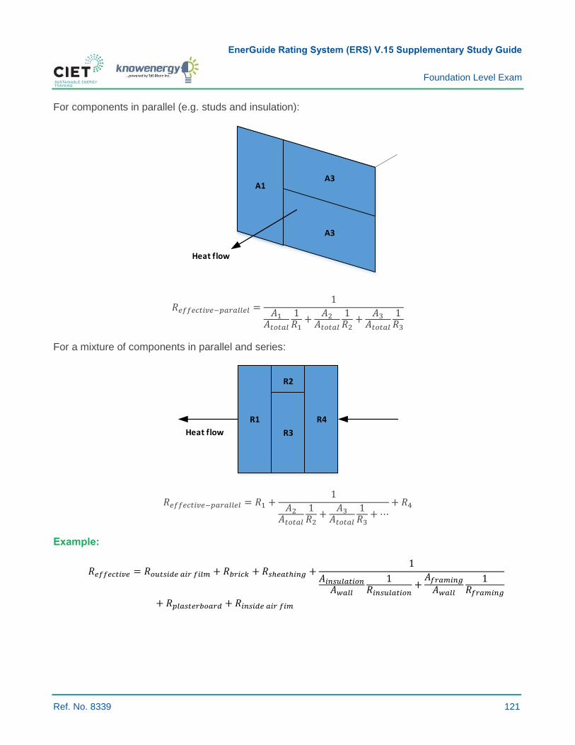
EnerGuide Rating System (ERS) V.15 Supplementary Study Guide
Foundation Level Exam
Ref. No. 8339 121
For components in parallel (e.g. studs and insulation):
A3
A3
A1
Heat flow
𝑅𝑒𝑓𝑓𝑒𝑐𝑡𝑖𝑣𝑒−𝑝𝑎𝑟𝑎𝑙𝑙𝑒𝑙 =1
𝐴1𝐴𝑡𝑜𝑡𝑎𝑙
1𝑅1
+𝐴2
𝐴𝑡𝑜𝑡𝑎𝑙
1𝑅2
+𝐴3
𝐴𝑡𝑜𝑡𝑎𝑙
1𝑅3
For a mixture of components in parallel and series:
R1
R2
R4
Heat flow R3
𝑅𝑒𝑓𝑓𝑒𝑐𝑡𝑖𝑣𝑒−𝑝𝑎𝑟𝑎𝑙𝑙𝑒𝑙 = 𝑅1 +1
𝐴2𝐴𝑡𝑜𝑡𝑎𝑙
1𝑅2
+𝐴3
𝐴𝑡𝑜𝑡𝑎𝑙
1𝑅3
+ ⋯+ 𝑅4
Example:
𝑅𝑒𝑓𝑓𝑒𝑐𝑡𝑖𝑣𝑒 = 𝑅𝑜𝑢𝑡𝑠𝑖𝑑𝑒 𝑎𝑖𝑟 𝑓𝑖𝑙𝑚 + 𝑅𝑏𝑟𝑖𝑐𝑘 + 𝑅𝑠ℎ𝑒𝑎𝑡ℎ𝑖𝑛𝑔 +1
𝐴𝑖𝑛𝑠𝑢𝑙𝑎𝑡𝑖𝑜𝑛𝐴𝑤𝑎𝑙𝑙
1𝑅𝑖𝑛𝑠𝑢𝑙𝑎𝑡𝑖𝑜𝑛
+𝐴𝑓𝑟𝑎𝑚𝑖𝑛𝑔
𝐴𝑤𝑎𝑙𝑙
1𝑅𝑓𝑟𝑎𝑚𝑖𝑛𝑔
+ 𝑅𝑝𝑙𝑎𝑠𝑡𝑒𝑟𝑏𝑜𝑎𝑟𝑑 + 𝑅𝑖𝑛𝑠𝑖𝑑𝑒 𝑎𝑖𝑟 𝑓𝑖𝑚
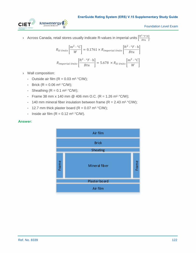
EnerGuide Rating System (ERS) V.15 Supplementary Study Guide
Foundation Level Exam
Ref. No. 8339 122
› Across Canada, retail stores usually indicate R-values in imperial units [ft2·°𝐹·h
𝐵𝑡𝑢].
𝑅𝑆𝐼 𝑈𝑛𝑖𝑡𝑠 [m2 · °𝐶
𝑊] = 0.1761 × 𝑅𝐼𝑚𝑝𝑒𝑟𝑖𝑎𝑙 𝑈𝑛𝑖𝑡𝑠 [
ft2 · °𝐹 · h
𝐵𝑡𝑢]
𝑅𝐼𝑚𝑝𝑒𝑟𝑖𝑎𝑙 𝑈𝑛𝑖𝑡𝑠 [ft2 · °𝐹 · h
𝐵𝑡𝑢] = 5.678 × 𝑅𝑆𝐼 𝑈𝑛𝑖𝑡𝑠 [
m2 · °𝐶
𝑊]
› Wall composition:
- Outside air film (R = 0.03 m²·°C/W);
- Brick (R = 0.06 m²·°C/W);
- Sheathing (R = 0.1 m²·°C/W);
- Frame 38 mm x 140 mm @ 406 mm O.C. (R = 1.26 m²·°C/W);
- 140 mm mineral fiber insulation between frame (R = 2.43 m²·°C/W);
- 12.7 mm thick plaster board (R = 0.07 m²·°C/W);
- Inside air film (R = 0.12 m²·°C/W).
Answer:
Fra
me
Mineral fiber
Fra
me
Sheating
Brick
Plaster board
Air film
Air film

EnerGuide Rating System (ERS) V.15 Supplementary Study Guide
Foundation Level Exam
Ref. No. 8339 123
Fram
e
Mineral fiber
Fram
e
140
mm
406 mm
38mm
𝑅𝑤𝑎𝑙𝑙 [m²°C
W] = 0.03 + 0.06 + 0.01 + 0.07 + 0.12 +
1
0.091
1.26 + 0.911
2.43
𝑅𝑤𝑎𝑙𝑙 = 2.53 [m²°C
W]
Question:
1 Calculate the R-value of a wall assembly with the following components:
R1 = 1 m²·°C/W
R2 = 1 m²·°C/W R3 = 3 m²·°C/W
R4 = 1 m²·°C/W
0.1m 0.9m
He
at fl
ow
a) 4.5 m²·°C/W.
b) 5.0 m²·°C/W.
c) m²·°C/W.
d) m²·°C/W.
Suggested Reading:
› Canadian Home Builders' Association. (2006). Insulation values. Builders’ Manual (6th Edition)
(Appendix 1).
Solution:
1. a)
EnerGuide Rating System (ERS) V.15 Supplementary Study Guide
Foundation Level Exam
Ref. No. 8339 124
7.2.30 DESCRIBE MOISTURE FLOW MECHANISMS
Key Concepts: Moisture flow; gravity; capillary action; airflow; diffusion.
Moisture Flow Mechanisms
Water moves from one place to another in many ways. The four most common means are:
1 Gravity.
2 Capillary action.
3 Air movement.
4 Diffusion.
Gravity:
› Water running down a roof or condensation running down a windowpane demonstrates how
gravity causes water to move downward.
› Gravity causes water in a liquid form to seek its lowest point by travelling the path of
least resistance.
Capillary Action:
› Capillary action is the ability of a liquid to flow in narrow spaces without the assistance of
external forces.
› Water moves sideways or upward by capillary action. Capillary action requires the presence of
very narrow spaces like those found in lapped siding or porous materials such as concrete or soil.
› In porous materials such as concrete and brick, water is drawn into small-diameter openings of
less than 5 mm (3⁄16 in.) by capillary action or wicking.
› Capillary action affects foundations made of concrete or other porous materials. The pores in the
concrete or mortar are long fine tubes. Water rises through capillary action up the foundation wall
or through a slab until it is released into an area with low water vapour pressure, usually inside a
basement or crawl space.
› Capillary action is also a factor to consider for above-grade walls. Surface water absorbed into the
cladding moves into other wall materials if there is no capillary break to stop the water transfer.
An air space between the exterior cladding and sheathing membrane eliminates such
capillary action.

EnerGuide Rating System (ERS) V.15 Supplementary Study Guide
Foundation Level Exam
Ref. No. 8339 125
Air Movement:
› Moisture in the form of water vapour is carried by moving air where, for example, there is an
opening in the house envelope.
› Moisture enters attics and wall cavities through airflow. Figure 35 below illustrates potential air
leakage locations whereby warm indoor air moves water vapour into a building envelope or
attic space.
› All potential leakage locations must be sealed to prevent warm moist air from exfiltrating into the
building envelope where condensation then occurs.
Figure 35: Air Leakage Locations46
46 Natural Resources Canada. (2016. 2 December). Typical Leakage areas [Online picture]. Retrieved from www.nrcan.gc.ca/energy/efficiency/housing/home-improvements/keeping-the-heat-in/comprehensive-air-leakage-control/15635

EnerGuide Rating System (ERS) V.15 Supplementary Study Guide
Foundation Level Exam
Ref. No. 8339 126
Diffusion:
› Water vapour moves directly through materials by diffusion. Diffusion depends on a difference in
water vapour pressure and a material’s resistance to said pressure (e.g. some paints help reduce
diffusion through drywall).
› Diffusion is a process whereby water vapour passes through a seemingly solid material.
› Just as heat flows from a warm to a cool area, water vapour flows from a high vapour pressure
area to a low vapour pressure area.
› Vapour diffusion is never stopped, but merely retarded by a vapour barrier (see Learning
Objective 5.1.8).
Comparing Airflow to Diffusion:
Studies have shown that approximately 100 times more moisture enters a building structure by airflow
than by diffusion under moderate pressure differences between the exterior and interior environments.
› This is why so much emphasis is placed on achieving an appropriate level of airtightness.
Question:
1 What is the difference between capillary action and diffusion?
a) Capillary action causes liquid water to move through porous materials or across small gaps,
whereas diffusion is a process whereby vapour passes through a seemingly solid material.
b) Capillary action causes liquid water to move through porous materials or across small gaps,
whereas diffusion is a process whereby vapour passes through air leakages in the
building envelope.
c) A hundred times more moisture can enter a building structure by capillary action than
by diffusion.
d) Moisture flow through diffusion can be stopped, whereas it can only be delayed for
capillary action.
Suggested Readings:
› Canadian Home Builders' Association. (2006). Building science. Builders’ Manual (6th Edition)
(Chapter 2).
› Natural Resources Canada. (2017). Planning, Design and Construction. Keeping the heat in
(Chapter 2) Retrieved from
http://www.nrcan.gc.ca/sites/www.nrcan.gc.ca/files/energy/pdf/housing/Keeping%20the%20Heat
%20In_e%20.pdf
Solution:
1. a)

EnerGuide Rating System (ERS) V.15 Supplementary Study Guide
Foundation Level Exam
Ref. No. 8339 127
7.2.40 DESCRIBE HOW MOISTURE FLOW WITHIN THE BUILDING ENVELOPE AFFECTS INDOOR AIR QUALITY
Key Concepts: Moisture flow; comfort; health; mould; relative humidity.
Summary:
› Insufficient humidity causes:
- Static electricity;
- Dry scratchy throats for occupants;
- Excessive dust problems;
- Damage to furniture and plants;
- Respiratory infections;
- Ozone production.
› Excessive humidity leads to:
- Condensation and mould formation;
- Growth of dust mites.
› Excessive or insufficient humidity increases the risk of:
- Bacteria;
- Viruses;
- Allergic rhinitis and asthma.
› Improper ventilation leads to areas of high and low humidity.
› Mould growing in a home releases mould spores, toxins, and odours, thus posing threats to the
health of household members.
› Figure 36 further below illustrates the impacts of high and low relative humidity levels on air quality.
Importance of Moisture Control:
› Control of moisture in all its forms is critical to making homes durable and comfortable.
› Building components and practices such as flashings, roofing and waterproofing the basement
protect the home from bulk water penetration.
› It is equally important to control the movement of water vapour to provide added protection for the
house structure and help maintain indoor humidity at a comfortable level.
EnerGuide Rating System (ERS) V.15 Supplementary Study Guide
Foundation Level Exam
Ref. No. 8339 128
Moisture in the Home:
› Even apparently dry houses with no leaks in basements or roofs can have moisture problems.
Here are some examples of sources of home moisture:
- A family of four produces about 50 litres (L) of water per week through normal
household activities;
- Where basement waterproofing is inadequate, groundwater can migrate through the foundation
by capillary action and evaporate on the surface of the wall or floor;
- A small plumbing leak can produce a lot of moisture;
- During humid weather periods, building materials and furnishings absorb moisture from the air
and then expel it during the heating season.
› Despite the water produced each day through general activity, most older constructions and even
newly built houses with abundant air leakage contain dry air in the winter.
- Cold outdoor air cannot carry much water vapour. In poorly sealed homes, uncontrolled airflow
brings colder drier air indoors and forces out warm moist air through openings in upper walls
and attics.
› Given the evolution of construction practices over the years, it is critical to know the era during
which a home was built. Knowing how wall systems were constructed is important when
considering building upgrades or adding mechanical ventilation.
Question:
1 How does moisture affect indoor quality?
a) Low relative humidity leads to condensation and the formation of mould.
b) Condensation leads to mould formation and the release of toxins in the air.
c) Water vapour leads to mould formation and the release of toxins in the air.
d) Low humidity levels improve air quality.
Suggested Readings:
› Natural Resources Canada. (2017). Planning, Design and Construction. Keeping the heat in (pp.
Chapter 2). Retrieved from
http://www.nrcan.gc.ca/sites/www.nrcan.gc.ca/files/energy/pdf/housing/Keeping%20the%20Heat
%20In_e%20.pdf
› Canada Mortgage and Housing Corporation. (2018). Moisture and air quality problems. Retrieved
April 13, 2018 from https://www.cmhc-schl.gc.ca/en/inpr/su/sufepr/sufepr_006.cfm
› Canadian Home Builders' Association. (2006). Building science. Builders’ Manual (6th Edition)
(Chapter 2).
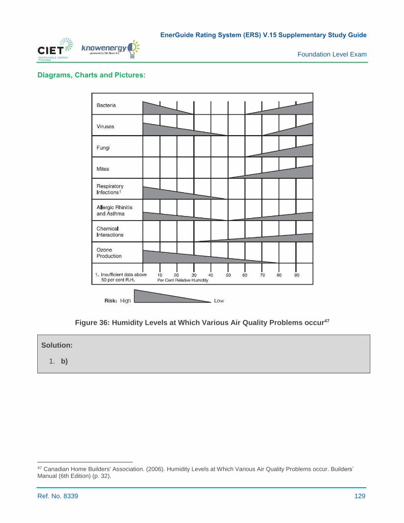
EnerGuide Rating System (ERS) V.15 Supplementary Study Guide
Foundation Level Exam
Ref. No. 8339 129
Diagrams, Charts and Pictures:
Figure 36: Humidity Levels at Which Various Air Quality Problems occur47
Solution:
1. b)
47 Canadian Home Builders' Association. (2006). Humidity Levels at Which Various Air Quality Problems occur. Builders’ Manual (6th Edition) (p. 32).
EnerGuide Rating System (ERS) V.15 Supplementary Study Guide
Foundation Level Exam
Ref. No. 8339 130
7.2.41 LIST THE CAUSES OF EXTREMELY LOW HUMIDITY LEVELS AND THEIR IMPLICATIONS
Key Concepts: Relative humidity; health; comfort.
Summary:
› Low in-house relative humidity is caused by low relative humidity air coming from the outside
through infiltration or ventilation.
› Heating during the cold season further contributes to lowering air relative humidity levels.
Relative Humidity (RH):
› Expressed as a percentage, RH refers to the quantity of water vapour in the air relative to the
maximum amount of water vapour it can hold at a given temperature.
› As temperature rises, the maximum or equilibrium vapour pressure increases, thus lowering RH
levels if no additional water is added to the air.
› Human beings are comfortable in the 20 to 85 percent RH range, but studies show the optimum
range of comfort is between 30 and 55 percent.
Implications of Low Humidity Levels:
› Static electricity.
› Dry scratchy throats for occupants.
› Excessive dust problems.
› Damage to furniture and plants.
› Respiratory infections.
› Ozone production.
Question:
1 Which of the following is not an effect of extremely low humidity in a house?
a) Frosting and fogging of windows.
b) Ozone production.
c) Respiratory Infections.
d) Excessive dust problems.
Suggested Readings:
› Canadian Home Builders' Association. (2006). Building science. Builders’ Manual (6th Edition)
(Chapter 2).
› Natural Resources Canada. (2017). Planning, Design and Construction. Keeping the heat in
(Chapter 2). Retrieved from
http://www.nrcan.gc.ca/sites/www.nrcan.gc.ca/files/energy/pdf/housing/Keeping%20the%20Heat
%20In_e%20.pdf

EnerGuide Rating System (ERS) V.15 Supplementary Study Guide
Foundation Level Exam
Ref. No. 8339 131
Solution:
1. a)
EnerGuide Rating System (ERS) V.15 Supplementary Study Guide
Foundation Level Exam
Ref. No. 8339 132
7.3.10 PROVIDE SOME EXAMPLES OF MATERIALS THAT CONTAIN ASBESTOS
Key Concepts: Asbestos; vermiculite insulation.
Summary:
› In the past, Asbestos was a popular material widely used in more than 3,000 building materials
from the 1950s to 1990s.
› If you are renovating or demolishing a house or building built before 1990, at least some parts
most likely contain asbestos.
› It poses health risks only when fibres are present in the air that people breathe, such as in
renovation projects whereby walls, ceilings, floors, and equipment are opened and dismantled.
› Many old construction materials contained asbestos.
Asbestos:
› Asbestos is the generic name for a variety of fibrous minerals found naturally in rock formations
around the world.
› Asbestos is usually white or greyish-white and may be used in a powder or fibrous form.
› It was used because it is an economically sound reinforcing, insulating and fireproofing material.
› Asbestos inhalation is associated with:
- Asbestosis: a scarring of the lungs, which makes it difficult to breathe;
- Lung cancer: smoking can greatly increase this risk;
- Mesothelioma: a cancer affecting the lining of the chest or abdominal cavity; and
- Pleural thickening: a lung disease.
› If you find asbestos, check with local or regional health authorities to determine the procedure to
follow or consult a professional qualified to work with asbestos.
Potential Asbestos-containing Products and Materials:
Here is a non-exhaustive list of potential asbestos-containing products and materials:
› Roof felt and shingles.
› Loose blown-in insulation such as
vermiculite.
› Incandescent light fixture backing.
› Roof gutters made of asbestos cement.
› Artificial fireplace logs and ashes.
› Acoustic tiles.
› Deck undersheathing.
› Soffit boards made of asbestos cement or
asbestos insulating board.
› Textured or stipple-coated walls
and ceilings.
› Asbestos cement board (e.g. transite)
siding and undersheathing.
› Outlets and switches.

EnerGuide Rating System (ERS) V.15 Supplementary Study Guide
Foundation Level Exam
Ref. No. 8339 133
› Asbestos pads under a fireplace hearth.
› Pipe insulation.
› Main panel and fuse box; each fuse wire
has an individual asbestos flash guard.
› Door and gasket covers.
› Backing behind recessed lighting.
› Boiler and furnace insulation.
› Stucco (ceiling covering).
› Gypsum board filling compound, patching
and joint compound for walls and ceilings.
› Window putty.
› Vinyl tiles and linoleum sheet flooring.
› Downpipes made of asbestos cement.
› Insulation on electrical wires.
› Wood stove heat reflectors.
› Flooring adhesive.
All these can release asbestos in the air by being disturbed, sanded, drilled, scraped, brushed, rubbed,
cut, damaged, broken apart, removed, etc.
Vermiculite Insulation:
› Vermiculite is a mineral mined around the world that has been widely used as insulation because
of its good thermal and fire-resistant qualities.
› Some vermiculite insulation may contain asbestos fibres.
› From the 1920s to 1990, a vermiculite ore produced by the Libby Mine in Montana, USA, may
have contained asbestos. It was sold in Canada as Zonolite® Attic Insulation and possibly as
other brands.
› Not all vermiculite insulation produced before 1990 contains asbestos fibres.
› However, to be safe in the absence of evidence to the contrary, it is reasonable to assume that, if
a house has older vermiculite insulation, it might contain some asbestos.
› The installation of vermiculite attic insulation occurred from approximately the 1950s until the
material was removed from the Canadian market in the mid-to-late 1980s.
› If vermiculite is contained in walls or attic spaces and is not disturbed, it poses very little risk to
occupant health. However, if it is exposed or disturbed, as in during a renovation, it can cause
health risks.
› If you find vermiculite insulation inside a home, do not disturb it.
› Make sure:
- Children are not allowed in the attic;
- The attic is not used for any reason;
- Professionals that are trained to handle asbestos are hired if you plan to remodel or renovate;
- All cracks and holes in the room ceilings below the insulation are sealed;
- Caulking around light fixtures and the attic hatch is applied to prevent insulation from
falling through.
› If there is vermiculite insulation in an attic, some material might have fallen inside the walls over
time. Therefore, cracks and holes should be sealed with caulking around:
- Window and door frames;
- Along baseboards;
- Around electrical outlets.
EnerGuide Rating System (ERS) V.15 Supplementary Study Guide
Foundation Level Exam
Ref. No. 8339 134
How to Test for Asbestos and Have it Safely Removed:
› Employers and owners/builders are responsible for determining if materials containing asbestos
are present at a jobsite before work begins.
› Products containing asbestos are very dense and do not release significant amounts of fibres
under normal use unless they are cut or damaged, thus releasing fibers into the air.
› Material containing asbestos or vermiculite should be properly labelled and isolated or sealed.
› Occupants should also be made aware of the presence of asbestos when renting or buying.
› To properly identify asbestos inside a building, a qualified testing company or asbestos surveyor
must be hired. The testing company or surveyor takes samples of possible asbestos-containing
materials in the house or building and sends them to a lab for testing. The surveyor will then
provide a report of the location of asbestos inside the home.
› Asbestos-containing materials must be removed and disposed of by trained and qualified workers
before renovation or demolition work begins.
Asbestos Regulation Today:
› A product composed entirely of asbestos cannot be sold to consumers today in Canada.
› Asbestos products applied by spraying must have asbestos fibres coated with a binder during
spraying so that they cannot come loose after drying.
› The Canadian government regulates the sale of certain high-risk consumer products made of
asbestos or that contain it (See Asbestos Products Regulations under Suggested
Readings below).
Question:
1 Which of the following statements is false regarding asbestos?
a) From the 1950s to 1990s, asbestos was a popular material widely used in more than 3,000
building materials.
b) Asbestos poses health risks only when fibres are present in the air that people breathe, such
as in renovation projects whereby walls, ceilings, floors or equipment are opened
and dismantled.
c) Vermiculite insulation does not contain asbestos.
d) If you are renovating or demolishing a house or building built before 1990, there is a strong
probability that at least some parts contain asbestos.

EnerGuide Rating System (ERS) V.15 Supplementary Study Guide
Foundation Level Exam
Ref. No. 8339 135
Suggested Readings:
› Government of Canada. (2018, 20 February). Health Risks of Asbestos. Retrieved from
www.canada.ca/en/health-canada/services/air-quality/indoor-air-contaminants/health-risks-
asbestos.html
› Government of Canada. (2018, 4 April). Asbestos Products Regulations. Retrieved from
laws-lois.justice.gc.ca/eng/regulations/SOR-2016-164/page-1.html#docCot
Diagrams, Charts, Pictures:
Figure 37: Asbestos Fibres on Rock48 and Vermiculite49
Solution:
1. c)
48 Wikipedia. (2018, 12 April). fibrous tremolite asbestos on muscovite [Online picture]. Retrieved from en.wikipedia.org/wiki/Asbestos#/media/File:Asbestos_with_muscovite.jpg. 49 Wikipedia. (2016, 8 August). Vermiculite after heating and ready to use [Online picture]. Retrieved from simple.wikipedia.org/wiki/Vermiculite#/media/File:Vermiculite1.jpg.

EnerGuide Rating System (ERS) V.15 Supplementary Study Guide
Foundation Level Exam
Ref. No. 8339 136
7.3.12 DESCRIBE THE CONCERNS ABOUT MOULD
Key Concepts: Mould; health issues; growth factors,
Description of Mould:
› Moulds are microscopic fungi.
› Moulds and fungi are found in nature and are necessary for the decomposition of leaves, wood
and other organic matter.
› They grow on organic material and can proliferate by forming spores.
› Many spores have a diameter of 2-3 micrometres; so they can become and stay airborne for
prolonged periods.
› These microorganisms enter a building directly or by spores carried in by the air.
- Airborne mould spores enter a house through open doorways and windows, as well as via
heating, ventilation and air-conditioning systems;
- Spores in outdoor air also attach themselves to airborne particles, people, pets and clothing.
Concerns:
› The presence of moulds does not always mean that health problems will occur. However for some
people, the inhalation of moulds, mould fragments, or spores can lead to health problems. In some
cases, moulds worsen certain health conditions.
› In addition, many kinds of mould make mycotoxins which are metabolites or by-products from
those moulds identified as toxic to humans. These toxins slowly wear down the immune system
and can lead to allergic or respiratory problems.
› In general, the most commonly reported symptoms include:
- Eye, nose, and throat irritation;
- Cough or congestion;
- Aggravation of asthma;
- Fatigue;
- Headaches;
- Difficulty concentrating.
› Moulds also exacerbate the symptoms of allergies, including wheezing, chest tightness, shortness
of breath, nasal congestion, and eye irritation. People who are immuno-suppressed or recovering
from surgery are usually more susceptible to health problems linked to moulds.
EnerGuide Rating System (ERS) V.15 Supplementary Study Guide
Foundation Level Exam
Ref. No. 8339 137
Prevention:
› Moulds grow almost everywhere and on any surface, provided that moisture is present. The best
method of mould prevention is to reduce the amount of moisture.
- Determine and eliminate sources of moisture;
- Keep relative humidity levels between 30 and 50 percent.
Where to Look for Mould:
› Visual inspection is the most reliable method for identifying mould problems. The most common
signs of water damage are discolouration and staining. Mould often appears as dark spots, stains
or patches in areas that have undergone water damage and where air movement lacks.
› While conducting an inspection, be sure to verify the following:
- Ceiling tiles;
- Walls including wallpaper and condition of drywall (Sheetrock®, gypsum wall boards);
- Cardboard or paper;
- Floors;
- Window sills;
- Insulation;
- Carpets;
- Furniture (condition of fabric, upholstery, etc.).
› If possible, look behind ductwork and walls (a mirror helps).
› Also look for standing water including puddles around and under sinks, bathtubs, drip pans for
dehumidifiers, air conditioners, and refrigerators. All these contribute to moisture in a building and
provide conditions where mould grows.
› Surface-sampling can be performed by scraping or swiping suspected spots, if needed, for
medical evaluation. This should be carried out by an experienced professional. Air monitoring is
also possible, but it is not considered routine.
› Monitoring devices are available. These measure the moisture level of drywall, wood, etc. Such
devices help indicate whether or not moisture levels favour mould growth.
Question:
1 Which of the following statements about mould is false?
a) Mould can lead to eye, nose, and throat irritation.
b) Mould is odourless and, as such, can only be detected visually.
c) Typically, mould is found in humid areas with a higher risk of condensation.
d) Moulds and fungi are found in nature.

EnerGuide Rating System (ERS) V.15 Supplementary Study Guide
Foundation Level Exam
Ref. No. 8339 138
Suggested Readings:
› Canadian Home Builders' Association. (2006). Indoor air quality. Builders’ Manual (6th Edition)
(Chapter 4).
› Canadian Centre for Occupational Health and Safety. (2017, 17 January). Mould. Retrieved from
https://www.ccohs.ca/topics/hazards/physical/mould/
Solution:
1. b)

Thank you for having taken the time to peruse this supplementary study guide.
We hope you found this material useful.
We wish you great success!