encouraging innovation in catalysis
TRANSCRIPT
Catalysis Today 93–95 (2004) 3–16
Encouraging innovation in catalysis
Frits M. Dautzenberg, Philip J. Angevine∗
Technology Development Center, ABB Lummus Global, Inc., Bloomfield, NJ, USA
Available online 11 August 2004
Abstract
Catalysis plays a critical role in virtually every industry. Often it is the key to making an entirely new technology or breathing new lifeinto an otherwise, mature technology. In addition to the continued needs for productivity improvements, environmental drives and heightenedindustrial safety add a new aspect to the importance of catalytic innovation.
ABB Lummus Global, along with its many industrial partners, has a well-established, track record of fostering innovation in its manytechnologies. These innovations take form in many ways: (a) catalyst design, (b) advanced materials, (c) new process concepts, (d) engineeringadvances, and (e) novel uses of high throughput screening.
Moving projects through the “technology pipeline” used to be done by brute force–using an army of scientists and engineers. Todaythat luxury no longer exists, and industry must embrace creative approaches to leverage their resources and accelerate the development andcommercialization of new technology. This paper presents specific examples of innovation at Lummus. These examples will, once again,reinforce the point that catalytic innovation is clearly an important vehicle to continued advancement of society.© 2004 Published by Elsevier B.V.
Keywords: R&D productivity; Innovation; Catalysis
1. Introduction
Industrial R&D, unlike traditional academic researchprojects, focuses on commercialization as the final ob-jective. Economic pressures almost inevitably push theresearchers to accelerate the timescale of the developmenteffort. In addition to this ever-present management mantra,the last 20 years or so have seen the shrinking of R&Dbudgets as an overriding phenomenon. Quite often one hasheard the painful and puzzling words “Do more with less.”Painful because it often involves downsizing and increasedproductivity demands upon the individual. Puzzling be-cause it seems to violate a thermodynamic law, or at least,simple logic. Given this backdrop of the current industrialR&D environment, one can immediately see the heightenedimportance of innovation. Moreover, since more than 90%of all industrial processes are catalytic in nature, fosteringinnovation in catalysis is an essential component for in-creasing the flow in the technology pipeline and, ultimately,adding value to business and society.
∗ Corresponding author. Tel.:+1-973-893-2514;fax: +1-973-893-2745.
E-mail address: [email protected] (P.J. Angevine).
This paper will show that nurturing innovation in catalysisis an effective way to boost R&D productivity. To encourageinnovation, five aspects will be discussed:
1. Business pull2. Technology push3. Advanced tools4. Industrial alliances5. University collaborations.
2. Business pull
Many scientific advances often begin with a specific needin mind. The electric light bulb and automobile are two clas-sic examples. Since the early days of electricity and auto-motive transportation, the needs have continuously evolved.Many of the business needs today revolve around envi-ronmental regulations. In petroleum refining, gasoline anddiesel fuel quality are changing in many dramatic ways.
To put the ultra-clean fuels “business pull” in perspective,let’s look at the general composition of gasoline and someof the major gasoline quality issues.Fig. 1 shows the com-position of gasoline. This pie chart is for U.S. gasoline, but
0920-5861/$ – see front matter © 2004 Published by Elsevier B.V.doi:10.1016/j.cattod.2004.05.019

4 F.M. Dautzenberg, P.J. Angevine / Catalysis Today 93–95 (2004) 3–16
17%
32%
7%
15%4%
11%
6%
7%
1%
Cat CrackedNaphtha
Straight RunNaphtha
AlkylateIsomerateButanes
Oxygenates
Hydrocrackate
Other
Reformate
Fig. 1. Composition of US gasoline.
the components and issues are similar worldwide. Of thevarious components, FCC gasoline (i.e. cat cracked naphtha)is the largest piece of the pie and is also the major sourceof sulfur. The U.S. Environmental Protection Agency (EPA)has developed a toxicity equation that quantifies the impactof the key pollutants. Sulfur is, by far, the primary pollu-tant problem. Reducing sulfur not only directly reduces SOx
emissions, but also improves the efficiency and effectivenessof catalytic converters, thereby also lowering NOx and COemissions. A second major gasoline component, reformate,is a major source of high octane due to its high aromat-ics content. Unfortunately, the aromatics include benzene,which is toxic, and therefore there is regulatory pressure toreduce it. Our joint venture partner, CDTECH®, has devel-oped catalytic distillation processes that effectively and effi-ciently remove benzene and sulfur from these two gasolinestreams.
Let’s move on along the pie chart to oxygenates (e.g.ethers, such as MTBE, ETBE, TAME). In the last decadewe have seen the use of oxygenate additives as a route tolower the CO emissions in gasoline. Unfortunately, one ma-jor oxygenate, MTBE, is being restricted in some countriesdue to its toxicity and water solubility. The opportunity here
Fig. 2. Thin film catalyst for alkylation.
Fig. 3. Typical AlkyCleanSM process reactor scheme.
is to identify cost-effective routes to other oxygenates, suchas ethanol.
The next significant piece of the pie is isomerate. Here, wemean products of C5 and C6 isomerization. These isoparaf-fins are “clean” (i.e. sulfur- and aromatics-free) and raisethe pool octane. The two major catalysts used in isomeriza-tion are halogenated aluminas and zeolites, both with noblemetal. Higher activity versions of these bifunctional cata-lysts should raise the iso-to-normal product ratio and therebyboost octane. Another paraffin component that could be acandidate for isomerization isn-heptane, but due to its re-activity, n-heptane is preferentially cracked to propane andiso-butane via conventional catalysts, instead of isomerizing.A recent breakthrough was achieved in this area at MIT in anABB-sponsored research project. Here, a noble metal/mixedmetal oxide catalyst has been shown to be very active andselective for isomerization and polyisomerization[1]. As itevolves, we expect this to be an important new process inthe ultra-clean fuels arena.

F.M. Dautzenberg, P.J. Angevine / Catalysis Today 93–95 (2004) 3–16 5
55˚C60˚C65˚C70˚C80˚C
92
93
94
95
96
97
98
99
100
0 22 44 66 88 110 132 154 176 198 220
Time (hrs)
RO
N
IN OUT TEMP
Fig. 4. Typical pilot plant results: cyclic operation with optimized catalyst, RON vs. time.
The last major piece of the pie is alkylate. Composedprimarily of C8 isomers, alkylate has virtually no toxicityand is very high in octane. As such, it could be the idealgasoline on its own, and demand for this environmentallyfriendly fuel is growing. However, conventional alkylationprocesses use hydrofluoric or sulfuric acids, both of whichpose serious safety and handling problems. To mitigate thisproblem refiners have long sought solid acid catalysts foralkylation—one of the great elusive challenges of refining.ABB Lummus Global, together with Akzo Nobel and For-tum Oy, have developed a solid acid catalyst process calledthe AlkyCleanSM alkylation technology.
R&D activities related to the AlkyClean technology[2]began in 1997 with investigating the merits of thin film cat-alysts (Fig. 2). A thin layer of active catalyst is deposited se-lectively on a solid support, such that the catalytic materials
Fig. 5. Reactor section of AlkyCleanSM demonstration plant.
do not penetrate the support[3]. The thinness of the highlyporous catalyst layer creates a very low diffusion barrier.As a consequence, formation of catalyst deactivating heavyby-products is suppressed, which leads to enhanced cata-lyst life and better product selectivity. Pursuing the under-standing gained with the thin film concept, a more practical,robust zeolite catalyst with controlled morphology was de-veloped[4]. Fig. 3is a schematic representation of the Alky-Clean reactor system. The two reactants,i-C4 and olefins(primarily butylene), are fed to multi-staged reactors. Sincethe catalyst deactivates quickly, other reactors are used inthe reaction sequence. While the catalysts in the first reac-tors undergo a mild H2 regeneration, the other reactors arebrought on stream. This sequence continues for hundreds ofcycles, and occasionally an extra reactor is swung into ser-vice while one reactor undergoes a higher temperature H2

6 F.M. Dautzenberg, P.J. Angevine / Catalysis Today 93–95 (2004) 3–16
Fig. 6. Novel zeolite synthesis procedure: “Dry-Synthesis”.
regeneration.Fig. 4 shows typical pilot plant data[2]. TheAlkyClean process is now in the final stages of development,and a large-scale demonstration unit is currently being op-erated in Porvoo, Finland (Fig. 5). Operation of this unit hasenabled us to confirm the overall soundness of the new tech-nology. It is anticipated that the AlkyClean technology cansuccessfully be introduced into refineries in the near future.
3. Technology push
Technology push can take many forms. These can includecatalyst design, reactor concepts, and new process designs.One concept under development at Lummus is in zeolite syn-thesis. Specifically, the innovation is morphology control toachieve ultra-small particles that have little or no mass trans-fer limitation. Intraparticle mass transfer limitations, impor-
0%
20%
40%
60%
80%
100%
ABB Commercial
Synthesis Technology
% o
f to
tal p
ore
vo
lum
e
>30 nm
5-30 nm
<5 nm
Fig. 7. Pore size distribution of two catalysts.
tant in fast reactions, often occur in industrial applicationswhere conversion levels are high. The Lummus innovationdeals with a zeolite synthesis procedure that we call “drysynthesis”[5,6]. Its name is based on the fact that the liquidreactants (e.g. caustic, water, and organic directing agent) areadded to the solid reactant (e.g. silica–alumina) at or belowthe incipient wetness point. Hence, the solid appears dry.
Fig. 6is a schematic representation of “dry synthesis”[7].On the left side is a preformed silica–alumina particle hav-ing mesopores within the solid oxide. On the right side, wesee the finished product. It retains the gross morphology ofthe original particle, and most of the silica–alumina has beenconverted to ultra-small molecular sieve crystals. InFig. 7,the pore size distribution is shown for the dry synthesis (left)versus a conventional zeolite synthesis (right). Note that the
Fig. 8. Aromatics alkylation: comparison of catalyst performance.

F.M. Dautzenberg, P.J. Angevine / Catalysis Today 93–95 (2004) 3–16 7
H2
- Heat
Dehydrogenation
C = CC - C
EB SM
Catalyst
Side reactions
CCH
4
BZ TOL
MethaneH
2+ Heat
1/2
+
C2H
4Ethylene
O2
Oxidation
+
O
Fig. 9. Process chemistry with oxidative reheat.
Fig. 10. New reactor system of Styrene Monomer Advanced Reheat Technology.
dry synthesis product has an unusually high amount of largemesopores (i.e. pores > 30 nm). The pore size distribution iscritical in many catalytic reactions because the mass trans-fer is impacted by a series of composite resistances. Twoexamples of improved catalytic performance are shown inFig. 8. Here, the reactions shown are aromatics alkylations,i.e. forming ethylbenzene and cumene. In this bar chart, thereference activities are normalized to 1.0. For the EB pro-cess, the “dry synthesis” zeolite shows an activity is morethan double the reference catalyst. For cumene production,the “dry synthesis” zeolite also shows a significant activityadvantage versus the reference catalyst. These examples aremerely for illustrative purposes; many other benefits of “drysynthesis” zeolites have been demonstrated.
Another technology innovation revolves around theethylbenzene (EB) dehydrogenation process that formsstyrene—the starting monomer for polystyrene.Fig. 9shows the overall reactions involved in styrene monomer(SM) production. Dehydrogenation of EB to SM is a highlyendothermic reaction, and as the temperature drops in an
adiabatic reactor, the yield becomes less favorable due tothermodynamic equilibrium. Other undesirable by-productsinclude benzene, toluene, and light gases like methane andethane. The new technology concept is to employ a secondreaction—simple oxidation of hydrogen to water—to addheat to the system and raise the overall average reactortemperature, thereby boosting the overall conversion. Onemethod to add heat is shown inFig. 10, where intrareactorreheat is employed in stages. This process design, known asSMART (Styrene Monomer Advanced Reheat Technology),has been commercialized in five plants.
Steam reforming:CH4 + H2O CO + 3 H2 ∆H˚298 = + 206 kJ/mol
Catalytic Partial Oxidation:
CH4 + ½ O2 CO + 2 H2 ∆H˚298 = - 36 kJ/mol
Fig. 11. Steam reforming and catalytic partial oxidation of methane.

8 F.M. Dautzenberg, P.J. Angevine / Catalysis Today 93–95 (2004) 3–16
Fig. 12. Composite structured packed (CSP) reactor with CPO catalyst system.
The same principle can be applied to steam reformingof methane, the primary method of hydrogen manufactureas well as syngas production. As shown inFig. 11, thisreaction is highly endothermic. The “heat input” approachcan now be applied via catalytic partial oxidation (CPO)of methane. With CPO, part of the methane is combustedto generate the energy to drive the endothermic steamreforming reaction. One innovation here is actually twoindependent concepts melded together to provide a syn-ergistic benefit. The first innovation is a novel Lummusreactor concept called composite structured packing (CSP)
Fig. 13. Typical catalytic partial oxidation results.
(Fig. 12). The second innovation is a true breakthrough—a“cokeless” steam reforming catalyst that was the result ofan ABB-sponsored collaborative project with the NationalUniversity of Singapore (NUS). CSP, with its high voidfraction and associated low pressure drop, is ideally suitedfor high superficial gas velocity applications such as this.In the preferred configuration, each reactor element has analternating packing of the two catalysts, i.e. the combustioncatalyst followed by the cokeless steam reforming catalyst.The catalyst proportions can be varied to optimize the tem-perature band.Fig. 13 shows the performance in a CPO

F.M. Dautzenberg, P.J. Angevine / Catalysis Today 93–95 (2004) 3–16 9
Fig. 14. CPO combined with steam reforming.
reactor using our novel supported metal-alloy catalyst. Notethat the product composition is essentially at equilibriumeven with this extremely high space velocity. InFig. 14, the“methane conversion” versus “time on stream” shows thatthis catalyst system is unusually stable; no initial deactiva-tion period occurs, consistent with its non-coking behavior.A second but important benefit of this catalyst combina-tion system is the closer approach to thermal neutrality,
Fig. 15. Furnace flow patterns (a) and heat flux profiles (b) in ethylene heaters.
thus simplifying heat management and improving thermalefficiency.
4. Utilization of advanced tools
The development of new catalytic technology often re-quires effective deployment of a multi-disciplined team.In addition to using diverse skills, many advanced toolsare employed, ranging from dynamic process simulators,to advanced control, and kinetic modeling. Computationalfluid dynamics (CFD) is one of the advanced tools we fre-quently use in reaction engineering. One example is shownin Fig. 15, where the combustion products’ flow patternsare used to design new ethylene heaters. Here, the objec-tives are to optimize heat input distribution and to minimizeNOx emissions. In many situations, this effort can reduce oreven eliminate the need for a selective catalytic reduction(“SCR”) unit downstream of the furnace. The left picture isa simulation in which the flow patterns are depicted by the-oretical particle pathlines, and the right plot is the relativeheat flux profile. Note that the model closely predicts theexperimental results. We have used CFD in the develop-ment of many processes, including the AlkyClean processto control the localiso-butane to butylene ratio as a meansto optimize product selectivity and catalyst stability.
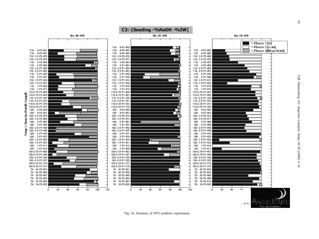
Another advanced tool is high throughput screening(HTS). Many applications of this powerful technique havebeen previously described for catalyst testing, and Lummus
10F.M
.D
autzenberg,P.J.
Angevine
/Catalysis
Today93–95
(2004)3–16
Fig. 16. Summary of HTS synthesis experiments.

F.M. Dautzenberg, P.J. Angevine / Catalysis Today 93–95 (2004) 3–16 11
Fig. 17. Comparison of conventional and “Dry-Syn” Y crystallites.
has used this approach in catalysis in several areas. How-ever, the example discussed here is quite different. Workingwith Avantium NV, we set out to devise a rapid screeningmethod for zeolite synthesis. Our goal was to crystallize ze-olite Y at the sub-micron scale—the region normally limitedto templated zeolites such as ZSM-5 and zeolite Beta. InFig. 16 we see a summary of many synthesis experimentswhere several parameters were varied[8]. Each bar repre-sents one experiment. Shown are three major products: un-converted material (Phase 1), undesirable by-products suchas cancrinite (Phase 2), and the targeted product, zeolite Y(Phase 3). Looking at this map one can quickly “zero in” onthe experiments where zeolite Y is the predominant prod-uct. Of course, this is just the beginning of the analysis.After that, one must still measure percent crystallinity, sur-face area, hydrocarbon sorption capacity, and ultimate crys-tal size.Fig. 17 shows the dramatic success of this study.The left picture shows a typical zeolite Y crystal size of 0.5micron, and the right picture shows our product of 0.02–0.05micron. We believe that this zeolite Y’s crystal size is lowerthan any other reported in the literature. Since zeolite Y isthe catalytic workhorse of the refining industry, one can im-mediately imagine its potential value in reactions that arelimited by intraparticle mass transfer.
5. Industrial alliances
In order to accelerate process development and stimulateinnovation, cooperative partnerships can be helpful, espe-cially if each partner has different and complementary capa-bilities. Our previously described AlkyClean process projectbrought together ABB Lummus Global (a diverse engineer-
ing and technology company), Akzo Nobel (a world leaderin catalyst manufacturing), and Fortum Oy (a Finnish re-fining company with a track record of embracing innova-tion and environmental responsibility). In addition, we haveformed three technology joint ventures:
• CDTECH, with CR&L (a CRI International company)• Chevron Lummus Global, with ChevronTexaco• Novolen Technology Holdings, with Equistar.
The example described here will revolve aroundCDTECH, where catalytic distillation was developed. Asthe phrase implies, catalytic distillation (CD)[9] involves si-multaneous reaction and product distillation. CD processesare particularly well suited for processes where the feed andproduct have a different boiling range, thereby facilitatingseparation and enhancing selectivity. The predominantlyliquid phase facilitates heat management and aids catalystlife stability. The family of CD technologies is quite broad,and today the number of commercially licensed units isapproaching 150.
Table 1 shows some of the CD applications that havebeen commercialized[10–12]. One major example is
Table 1Commercial applications of catalytic distillationa
Etherification (MTBE, TAME and ETBE)Aromatics alkylation (EB and cumne)Benzene removal from reformateSelective desulfurizationVarious selective hydrogenations
a Demonstration plant of Tianjin, China Front-end CDHydro® processfor ethylene plants (2003).
12 F.M. Dautzenberg, P.J. Angevine / Catalysis Today 93–95 (2004) 3–16
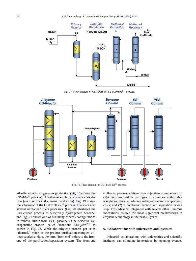
Fig. 18. Flow diagram of CDTECH MTBE (CDMtbe(r)) process.
Fig. 19. Flow diagram of CDTECHEB® process.
etherification for oxygenates production (Fig. 18) shows theCDMtbe® process). Another example is aromatics alkyla-tion (such as EB and cumene production).Fig. 19 showsthe schematic of the CDTECHEB® process. There are alsoseveral ultra-clean fuels processes. (Fig. 20 illustrates theCDBenzene process to selectively hydrogenate benzene,andFig. 21shows one of our many process configurationsto remove sulfur from FCC gasoline.) One selective hy-drogenation process—called “front-end CDHydro®”—isshown in Fig. 22. While the ethylene process per se is“thermal,” much of the product purification complex uti-lizes catalysis. Here, the term “front end” refers to the frontend of the purification/separation system. The front-end
CDHydro process achieves two objectives simultaneously:(1)it consumes dilute hydrogen to eliminate undesirableacetylenes, thereby reducing refrigeration and compressioncosts; and (2) it combines reaction and separation in onestep. This advance, integrated with several other Lummusinnovations, created the most significant breakthrough inethylene technology in the past 25 years.
6. Collaborations with universities and institutes
Industrial collaborations with universities and scientificinstitutes can stimulate innovations by opening avenues

F.M. Dautzenberg, P.J. Angevine / Catalysis Today 93–95 (2004) 3–16 13
Fig. 20. New catalytic distillation technology—CDBenzene.
Fig. 21. FCC gasoline desulfurization via catalytic distillation.
for future technology developments. It can be a synergisticblend of new scientific concepts along with a “real-world”problem solving approach. While basic research at uni-versities can be different in purpose and approach thanapplied industrial research, it is often quite similar in ex-ecution. Project collaboration can lower the transition gapfrom basic to applied research. Furthermore, talented stu-dents, not yet hindered by “conventional thinking,” can beengaged in tackling difficult scientific challenges with cre-ative approaches not yet employed. Of note, the universityphilosophy is to publish research results as soon as possi-ble. This may lead to a conflict with the industrial partner,who wants to protect the intellectual know-how by patentsand trade secrets. Our experience has shown that this issuecan be managed if recognized and discussed at the projectoutset.
Some typical projects and the universities involved arelisted in Table 2. Two examples will be described in moredetail to illustrate how such projects can become the starting
point for promising new technologies: (1) micellar catalystsand (2) mesoporous materials.
6.1. Micellar catalysts
Homogeneous catalysts often are orders-of-magnitudemore active than heterogeneous catalysts, but suffer from
Table 2Collaborations with universities—some typical projects
Massachusetts Institute ofTechnology (MIT) Cambridge,USA
Mixed oxides hydroisomerizationcatalyst
Technical University of Delft,Eindhoven, The Netherlands
Catalytic route to ethylene andpropylene, Micellar catalyst
National University of Singapore,Singapore
Nano structured catalysts, Zeolitemembranes, Methane upgrading
Washington University, St. Louis,USA
Reactor studies for alkylation,Hydrodynamics of structuredcatalysts

14 F.M. Dautzenberg, P.J. Angevine / Catalysis Today 93–95 (2004) 3–16
Fig. 22. Application of front-end CDHydro(r) process in ethylene plants.
product/catalyst separation difficulties. As such, the anchor-ing of homogeneous catalysts has become an importantresearch effort. One new technique of “heterogenizing” ho-mogeneous catalysts involves encapsulating the catalyst ina porous, micellar structure made of surfactant molecules[13,14]. Several reactions have been investigated, includingpropylene oxidation using hydrogen peroxide as the oxidant[15] (Fig. 23). The results are very encouraging, showingthat the reaction can occur at an appreciable rate with highselectivity at mild operating conditions. A conceptual pro-cess design (Fig. 24) based on these results indicates thatthe new technology may potentially become attractive dueto its inherent simplicity[16]. By-product-free propyleneoxide can be made at a considerably lower cost versusconventional technology. This is understandable since the
Fig. 23. Olefin epoxidation by a micelle-incorporated homogeneous catalyst.
complexity of the current propylene oxide/styrene monomertechnology requires substantially higher capital investment.Further development of the new propylene oxide processseems to be warranted, especially if the micellar catalyst’sstructural stability can be made less prone to attack byhydrogen peroxide.
6.2. Mesoporous materials
Industrial and academic researchers have long sought tosynthesize larger pore materials, i.e. larger than the poresof microporous zeolites. Conceptually, these “meso-porous”materials (i.e. with pores larger than 2 nm) should be use-ful for processing high molecular weight materials, such aspetroleum residua, lubricants, amino acids, etc.

F.M. Dautzenberg, P.J. Angevine / Catalysis Today 93–95 (2004) 3–16 15
Fig. 24. Conceptual process flow diagram for propylene oxide.
Since discovery of the M41s family of crystalline meso-porous materials[17,18], an enormous worldwide effort hasbeen expended on synthesis, characterization, and catalyticapplication. Unfortunately, these M41s materials generallylacked significant catalytic activity and also suffered frommarginal structural, thermal, and hydrothermal stability.Many research programs sprung up to transform M41s into
Fig. 25. XRD pattern and TEM of TUD-1.
active and stable forms, but with mixed success. Manyscientists then focused on other mesoporous materials, butso far no materials have shown to be both scientificallysignificant and relatively inexpensive to make.
In the late 1990s, Lummus established a joint re-search project with the Technical University of Delft (TheNetherlands). The project’s objective was to synthesize an

16 F.M. Dautzenberg, P.J. Angevine / Catalysis Today 93–95 (2004) 3–16
industrially relevant, mesoporous material. The team dis-covered an entirely new family of mesoporous materials,now known as “TUD-1”[19–21]. Fig. 25 shows a typicalX-ray diffraction pattern and TEM (transmission electronmicrograph) of TUD-1. Using a novel characterization tech-nique, TUD-1 has been shown to be an ultra-large pore,amorphous material having random, three-dimensional, in-terconnecting pores—very much like a molecular-scale ver-sion of a ceramic foam. Synthesis parameters can be variedto custom tailor the pore sizes and to make an extremelywide range of chemical variants (e.g. Si, Al, Ti, Cr, Sn, Ga,etc.) As a result, TUD-1 has been shown to be dramaticallysuperior to other mesoporous materials. Compared to M41s,TUD-1 has significantly broader catalytic utility as well asenhanced structural, thermal, and hydrothermal stability. Ithas been shown to be an important catalyst for selectiveoxidation, acylation (for fine chemicals), hydrogenation,hydrotreating for ultra-clean fuels, and many other applica-tions. While the conventional wisdom was that mesoporousmaterials’ primary utility would be for high molecularweight chemicals, TUD-1 can also be an effective catalystfor many fast reactions where mass-transfer limitations playan important role. We have also shown that zeolite/TUD-1composites can have a totally unexpected, synergistic cat-alytic value. It is fair to say that we have just touched the“tip of the iceberg” in the TUD-1 catalysis story.
7. Conclusion
Based on the examples laid out in this paper, it is easy tosee that many factors can come into play in fostering innova-tion in catalysis. Each of these drivers has its own, unique di-mension. Taken together, they form a patchwork with manynuances and interplay. The derived synergies make them farmore valuable together than merely the sum of the individ-ual drivers. The end goal is to mold these drivers and reapthe benefits of catalysis to create value for a better society.
References
[1] J.Y. Ying, J. Xu, Nanocomposite Materials for Solid Acid Catalysis,US Patent application 20 030 069 131 (April 10, 2003).
[2] E.H. Broekhoven, V.J. D’Amico, P.J. Nat, H. Nousiainen, J. Jakkula,The AlkyCleanSM Process: A New Solid Acid Catalyst GasolineAlkylation Technology, Paper presented at NPRA 2002 Annual Meet-ing San Antonio, March 17–19, 2002.
[3] H.E. Barner, C. Ercan, A. Khonsari, J.T. Kwon, L.L. Murrell, A.Westner, F.M. Dautzenberg, Thin Film Solid Acid Catalyst for Re-finery Alkylation, Paper presented at the ATP 1998 Fall Meeting,Atlanta, November 17–18, 1998.
[4] E.I. Van Broekhoven, F.R. Mas Cabre, P. Bogaard, G. Klaver, M.Vonhof, Process for Alkylating Hydrocarbons, US Patent 5 986 158(November 16, 1999).
[5] L.L. Murrell, R.A. Overbeek, Y.-F. Chang, N. van der Puil, C.Y. Yeh,Method of Making Molecular Sieves and Novel Molecular SieveComposites, US Patent 6 004 527 (1999)
[6] N. Van der Puil, F.M. Dautzenberg, J.H. Koegler, Synergy (2000)June (an ABB Oil, Gas and Petrochemical Division).
[7] F.M. Dautzenberg, Hydro- and Dehydrogenation of Large VolumePetrochemicals, Paper presented at the 10th Roermond Conferenceon Catalysis, Rolduc-Kerkrade, June 30–July 5, 2002.
[8] F.M. Dautzenberg, Intra-reactor Process Intensification, Paper pre-sented at the Symposium for Emerging Technologies, Antwerp, Bel-gium, May 16, 2003
[9] L.A. Smith, Jr., Catalytic distillation Structure. US Patent 4 443 559(April 17,1984).
[10] A. Sy, L. Smith, J. Chen, F.M. Dautzenberg, Catalytic distillationroute for cumene. DeWitt Petrochem. Rev., Houston, March 23, 1993.
[11] K. Rock, G.R. Gilbert, T. McGuirk, Catalytic distillation extend itsreach, Chem. Eng. 78 (1997) 78–84.
[12] D. Hearn, H.M. Putman, Hydrodesulfurization Process Utilizing aDistillation Column Reactor, US Patent 5 779 883 (March 17, 1998).
[13] T.D. Maden, P.J. Quinn, Biochem. Soc. Trans. 6 (1978) 1345–1347.[14] B. Fell, C. Schobben, G.J. Papadogiankis, Mol. Catal. 101 (1995)
179.[15] J.H.M. Heijnen, V.G. de Bruyn, L.J.P. Van den Broeke, J.T.F. Keuren-
tjes, Chem. Eng. Proc. 42 (2003) 223.[16] J.H.M. Heijnen, Olefin Epoxidations Catalyzed by Micelle-
Incorporated Homogeneous Catalysts, Ph.D. thesis in Chemical En-gineering, Technical University of Eindhoven, 2003.
[17] US Patent 5 098 684 (March 24, 1992) (assigned to Mobil Oil),US Patent 5 102 643 (April 7, 1992) (assigned to Mobil Oil), USPatent 5 057 296 (October 15, 1991) (assigned to Mobil Oil), USPatent 5 108 725 (April 28, 1992) (assigned to Mobil Oil), US Patent5 198 203 (March 30, 1993) (assigned to Mobil Oil).
[18] C.T. Kresge, M.E. Leonowicz, W.J. Roth, J.C. Vartuli, J.S. Beck,Nature 359 (1992) 710.
[19] Z. Shan, Th. Maschmeyer, J.C. Jansen, Inorganic Oxides with Meso-porosity or Combined Meso- and Microporosity and Process for thePreparation Thereof, US Patent 6 358 486 (March 19, 2002).
[20] Z. Shan, E. Gianotti, J.C. Jansen, J.A. Peters, L. Marchese, Th.Maschmeyer, Chem. Eur. J. 7 (7) (2001) 1437–1443.
[21] J.C. Jansen, Z. Shan, L. Marchese, W.V.D. Zhou, N. Puil, Th.Maschmeyer, Chem. Commun. (2001) 713–714.