enclosing systems wall cladding systems - oten€¦ · enclosing systems wall cladding systems...
TRANSCRIPT
Enclosing systems
Wall Cladding Systems Cladding systems enclose the building frame. They provide protection from the weather and
can contribute to the comfort, aesthetics and sometimes the structural adequacy of a
building.
Wall cladding can be broadly classified as:
• board cladding or boarding - with flat, textured or profiled finish
• sheet cladding - with flat, textured or profiled finished sheets
• impervious coatings - applied over cladding and solid walls
Board Cladding Boarding may be made from:
• solid timber
• fibre cement - using cellulose fibres and cement binder
• hardboard - a reconstituted timber product
• aluminium
• plastic
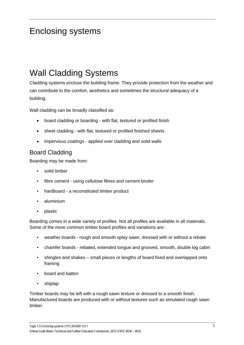
Boarding comes in a wide variety of profiles. Not all profiles are available in all materials. Some of the more common timber board profiles and variations are:
• weather boards - rough and smooth splay sawn, dressed with or without a rebate
• chamfer boards - rebated, extended tongue and grooved, smooth, double log cabin
• shingles and shakes – small pieces or lengths of board fixed and overlapped onto framing
• board and batten
• shiplap
Timber boards may be left with a rough sawn texture or dressed to a smooth finish. Manufactured boards are produced with or without textures such as simulated rough sawn timber.
Topic 1.5 Enclosing systems CPCCBS6001 Ed 1 1 © New South Wales Technical and Further Education Commission, 2015 (TAFE NSW – WSI)
Timber wall cladding profiles
Installation Boards may be installed horizontally or at an angle with some profiles also used vertically. Angled and vertical cladding requires a vapour barrier behind as capillary action can cause water to penetrate where the boards join or lap over each other.
Boards may:
• lap over each other - usually installed horizontally but sometimes used on an angle up to 15° or 20°
• fit into a rebate on the thick edge - usually installed horizontally but sometimes used on an angle up to 15° or 20°
• fit together using a tongue and groove - all angles
2 Topic 1.5 Enclosing systems CPCCBS6001 Ed 1 © New South Wales Technical and Further Education Commission, 2015 (TAFE NSW – WSI)
• not lap but have batten cover strips over gaps between the boards - vertical boards
only Butt end joins for boards should occur at a stud but some of the manufactured boards can use ‘off-stud’ joiners. This permits greater economies to be achieved as the manufactured boards are usually only available in one, or possibly two, set lengths.
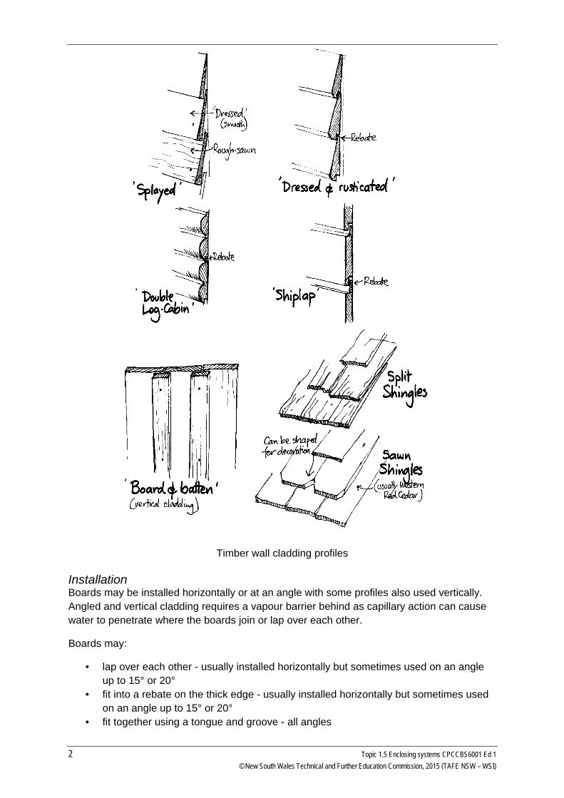
Internal and external corners require special attention. Treatments include:
• mitre cut - used for external corners for timber boards • profile cut - used for internal corners for dressed timber boards • timber stops - used for internal and external corners for all boards • corner moulds - used for internal and external corners for manufactured boards •
Other areas requiring special attention occur at openings and service penetrations.
External corners and moulding
Topic 1.5 Enclosing systems CPCCBS6001 Ed 1 3 © New South Wales Technical and Further Education Commission, 2015 (TAFE NSW – WSI)
Sheet cladding Sheet cladding is made from:
• fibre cement
• hardboard
• plywood
• Autoclaved Aerated Concrete (AAC)
• polystyrene and composite sheeting
• metal
The sheets may be finished with a surface that is:
• smooth
• textured
• grooved - to imitate boarding with either random or equal spaced grooves
Installation Sheet cladding is generally installed with only vertical joints as horizontal joints require special provisions to eliminate access for water.
All joints in sheet cladding should be backed by timber to keep both edges in line. Joints can be
• exposed butt joints - with either a DPC or neoprene waterstop behind
• over laid with cover strips - timber batten or purpose made
• fitted with joint moulds - plastic ‘H’ section strips
• taped and sealed with water proof sealer - usually used under affixed texture finishes such as texture paints or ‘Granosite’ finish.
Impervious coatings Impervious coatings are applied over cladding such as fibre cement, polystyrene sheet, AAC, masonry veneer or sold walls such as AAC.
The area applying to the cladding of buildings that the drafter or building designer needs to pay particular attention to as part of the building design is that of water and moisture entry into the interior of the building. Points where this is likely include:
• at joints and laps of the cladding
• at joints between different claddings
• all round windows, doors and openings
• changes of direction such as corners
4 Topic 1.5 Enclosing systems CPCCBS6001 Ed 1 © New South Wales Technical and Further Education Commission, 2015 (TAFE NSW – WSI)
Brick Veneer This is the combination of a single brick skin, a cavity and a timber or steel frame. Brick veneer construction is an Australian development. It combines masonry construction from England and lightweight timber frame construction from California.
The brickwork is used as a cladding only and generally preforms no structural function for the building. As a cladding, it is there to protect the building and the occupants from the weather.
The veneer skin is built after the frame is erected, plumbed and straightened. Also all windows, door frames and stops should be in place before the brick/block layer commences. This permits the veneer to be accurately finished to prevent water penetrating at these points.
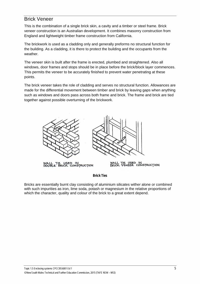
The brick veneer takes the role of cladding and serves no structural function. Allowances are made for the differential movement between timber and brick by leaving gaps when anything such as windows and doors pass across both frame and brick. The frame and brick are tied together against possible overturning of the brickwork.
Brick Ties
Bricks are essentially burnt clay consisting of aluminium silicates wither alone or combined with such impurities as iron, lime soda, potash or magnesium in the relative proportions of which the character, quality and colour of the brick to a great extent depend.
Topic 1.5 Enclosing systems CPCCBS6001 Ed 1 5 © New South Wales Technical and Further Education Commission, 2015 (TAFE NSW – WSI)
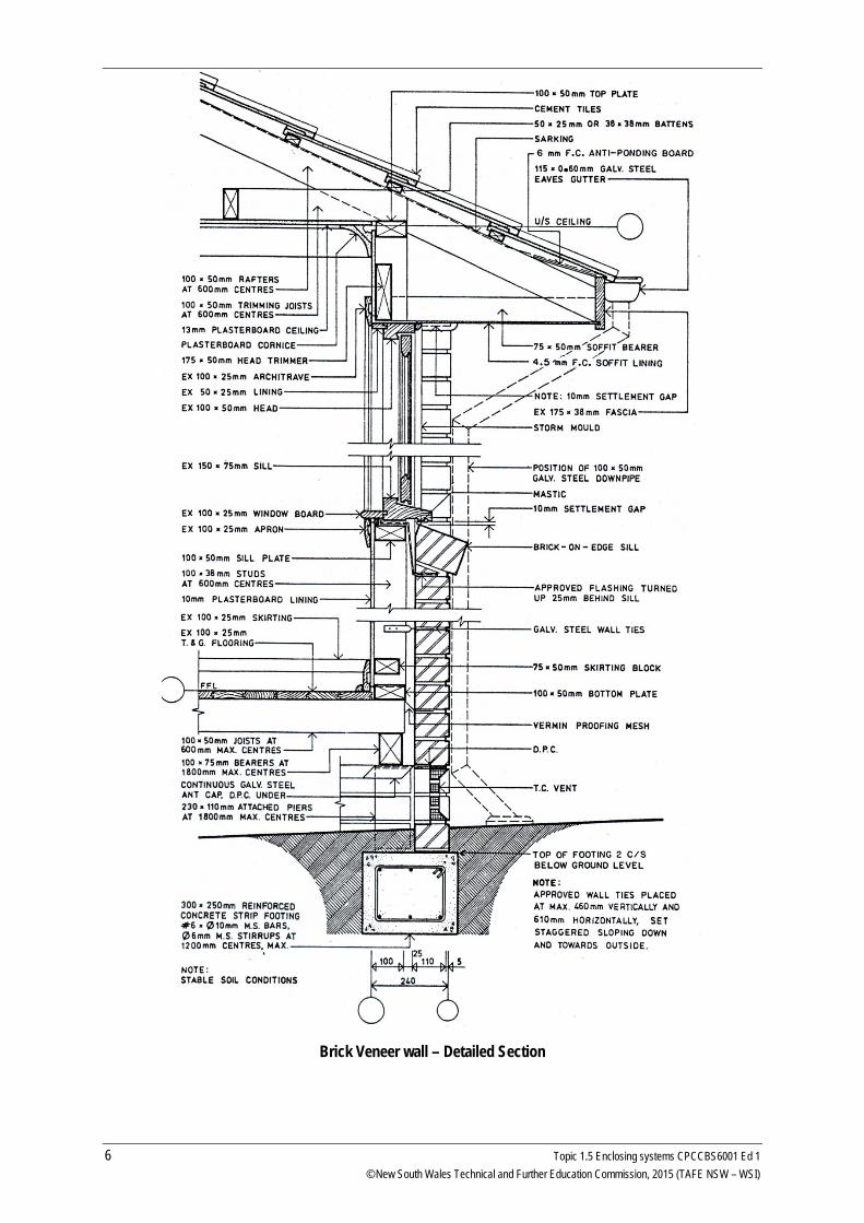
Brick Veneer wall – Detailed Section
6 Topic 1.5 Enclosing systems CPCCBS6001 Ed 1 © New South Wales Technical and Further Education Commission, 2015 (TAFE NSW – WSI)
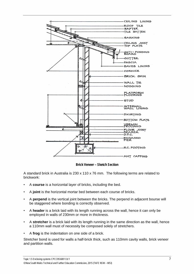
Brick Veneer – Sketch Section
A standard brick in Australia is 230 x 110 x 76 mm. The following terms are related to brickwork:
• A course is a horizontal layer of bricks, including the bed.
• A joint is the horizontal mortar bed between each course of bricks.
• A perpend is the vertical joint between the bricks. The perpend in adjacent bourse will be staggered where bonding is correctly observed.
• A header is a brick laid with its length running across the wall, hence it can only be employed in walls of 230mm or more in thickness.
• A stretcher is a brick laid with its length running in the same direction as the wall, hence a 110mm wall must of necessity be composed solely of stretchers.
• A frog is the indentation on one side of a brick.
Stretcher bond is used for walls a half-brick thick, such as 110mm cavity walls, brick veneer and partition walls.
Topic 1.5 Enclosing systems CPCCBS6001 Ed 1 7 © New South Wales Technical and Further Education Commission, 2015 (TAFE NSW – WSI)
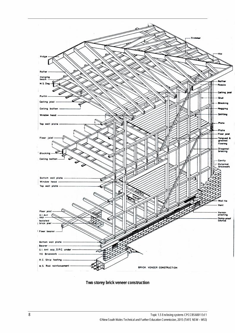
Two storey brick veneer construction
8 Topic 1.5 Enclosing systems CPCCBS6001 Ed 1 © New South Wales Technical and Further Education Commission, 2015 (TAFE NSW – WSI)
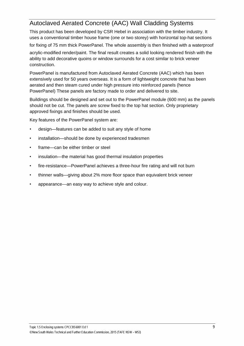
Autoclaved Aerated Concrete (AAC) Wall Cladding Systems This product has been developed by CSR Hebel in association with the timber industry. It uses a conventional timber house frame (one or two storey) with horizontal top-hat sections
for fixing of 75 mm thick PowerPanel. The whole assembly is then finished with a waterproof
acrylic-modified render/paint. The final result creates a solid looking rendered finish with the ability to add decorative quoins or window surrounds for a cost similar to brick veneer construction.
PowerPanel is manufactured from Autoclaved Aerated Concrete (AAC) which has been extensively used for 50 years overseas. It is a form of lightweight concrete that has been aerated and then steam cured under high pressure into reinforced panels (hence PowerPanel) These panels are factory made to order and delivered to site.
Buildings should be designed and set out to the PowerPanel module (600 mm) as the panels should not be cut. The panels are screw fixed to the top hat section. Only proprietary approved fixings and finishes should be used.
Key features of the PowerPanel system are:
• design—features can be added to suit any style of home
• installation—should be done by experienced tradesmen
• frame—can be either timber or steel
• insulation—the material has good thermal insulation properties
• fire-resistance—PowerPanel achieves a three-hour fire rating and will not burn
• thinner walls—giving about 2% more floor space than equivalent brick veneer
• appearance—an easy way to achieve style and colour.
Topic 1.5 Enclosing systems CPCCBS6001 Ed 1 9 © New South Wales Technical and Further Education Commission, 2015 (TAFE NSW – WSI)
More information and details for Hebel PowerPanel should be sourced from the manufacturer’s website www.hebelaustralia.com.au
There are numerous panels that now available for cladding and a web search will reveal all the different types and manufacturers. There are panels to suit particular situations such as fire retardant panels for high risk fire areas or sound insulating panels for acoustic separation.
Cavity Brick Cavity systems are a masonry constructed wall with mortar as the bonding agent. They have an inner and an outer masonry wall separated by an air gap or cavity. The two walls (called ‘leafs’ or ‘skins’) are held in place by metal ties (called cavity ties) fixed into the joints between courses of masonry. The outside leaf is the weather wall while the cavity should prevent any water that penetrates the outside wall from reaching the interior.
10 Topic 1.5 Enclosing systems CPCCBS6001 Ed 1 © New South Wales Technical and Further Education Commission, 2015 (TAFE NSW – WSI)
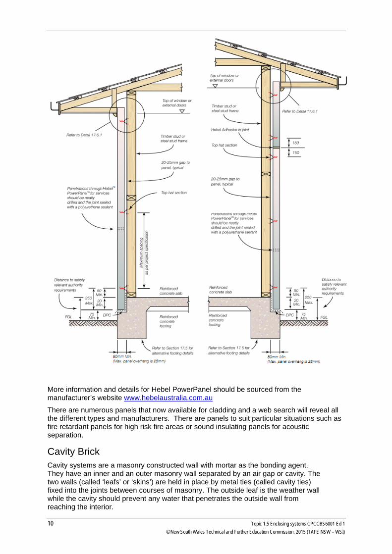
Cavity Brick wall Construction
Bricks are not moisture resistant and need to be protected from water to stop dampness entering the dwelling. Methods used to stop moisture entering the dwelling through the wall is to have a cavity (a gap of 50-60mm) between the two leaves of brickwork to break the contact and not permit the water to enter the inside face. To stop rising damp from the foundation a damp course must be placed above the ground level but below the floor level.
The down side of a cavity is that you end up with two thin walls unable to rely on each other for structural stability, therefore wall ties are introduced to improve stability. The inner wall is the one on which the load is supported and therefore may need strengthening by tying to the outer wall. (In some older buildings, the outer skin is the load-bearing wall)
Go to http://www.yourhome.gov.au/materials/cladding-systems and read more about wall cladding systems including:
• Reverse brick veneer
• Trombe walls
• Steel cladding
• Aluminium cladding
• Composite materials
• Vinyl
• other innovative ecological cladding products and ideas can be found by searching the internet. Try http://www.ecospecifier.com.au/
Topic 1.5 Enclosing systems CPCCBS6001 Ed 1 11 © New South Wales Technical and Further Education Commission, 2015 (TAFE NSW – WSI)
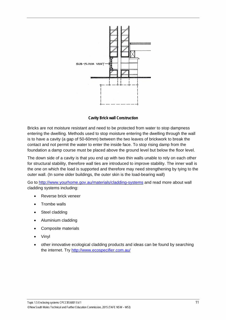
Eaves and Flashing
Tiled roof at eave
Roof overhangs (eaves) provide additional protection from the sun and rain to the walls.
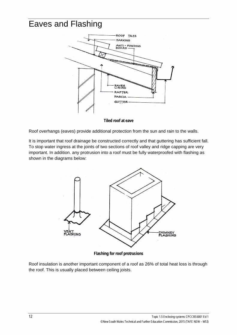
It is important that roof drainage be constructed correctly and that guttering has sufficient fall. To stop water ingress at the joints of two sections of roof valley and ridge capping are very important. In addition. any protrusion into a roof must be fully waterproofed with flashing as shown in the diagrams below:
Flashing for roof protrusions
Roof insulation is another important component of a roof as 26% of total heat loss is through the roof. This is usually placed between ceiling joists.
12 Topic 1.5 Enclosing systems CPCCBS6001 Ed 1 © New South Wales Technical and Further Education Commission, 2015 (TAFE NSW – WSI)
Flashing Flashings are metallic shields used to prevent the penetration of moisture through small gaps at junctions of roofs and vertical surfaces. They also direct water which has penetrated through the external cladding over openings to windows and doors to the outside. Under window sills, similar shields are used to prevent the penetration of water which has been blown in under the sill.
Flashings are to prevent water penetration occurring by building-in waterproof barriers during the construction of the building. They are used on heads and sills of window and door frames, chimney stacks, ventilation stacks, hoods, parapet walls, box gutters, roof slopes and flat roofs of a building and under buildings vulnerable to water penetration and wherever vulnerable points occur.
The building-in of head and sill flashing is required to all external openings. In brick cavity wall construction the flashing is built into the internal skin and crosses the cavity to slope outwards. In the window and door heads any accumulated water is released by means of weep holes, or by joints, left over the openings for this purpose. In timber frame construction the flashing is laid under the external covering at the head and covered over by an external architrave.
Where the external cladding is fibre cement, the flashing is covered by a specially moulded section of the same material. Flashing of the sill in cavity brickwork and brick veneer is similar; the hard wood sill in each case is bedded on the metallic flashing which is turned up at the back of the sill and carried across the cavity to the external skin below the brick sill line and kept in position at the time the sill bricks are laid.
Flashing to the hardwood sill in timber frame construction is by bedding of the flashing as before and projecting it approximately 25 mm over the external covering. It is then covered by a small timber bed mould.
Materials for flashing Metallic materials are to be used for this purpose such as lead, steel, copper, aluminium composites. They must be of sufficient width to allow bedding and crossing of cavities in brick and brick veneer construction.
Roof flashing Flashings are necessary to make watertight connections between a roof and another part of a building, including any upstands, such as flues, which penetrate the roof surface.
Typical positions requiring flashings are:
• gutters against a parapet or kerb
• walls against an abutting roof
• chimneys passing through roofs
• skylights
• pipes passing through roofs.
The choice of suitable flashing material is as important as the flashing itself. Some typical examples are lead, steel (galvanised, zinc-annealed or Colorbond finished), zinc, copper.
Topic 1.5 Enclosing systems CPCCBS6001 Ed 1 13 © New South Wales Technical and Further Education Commission, 2015 (TAFE NSW – WSI)
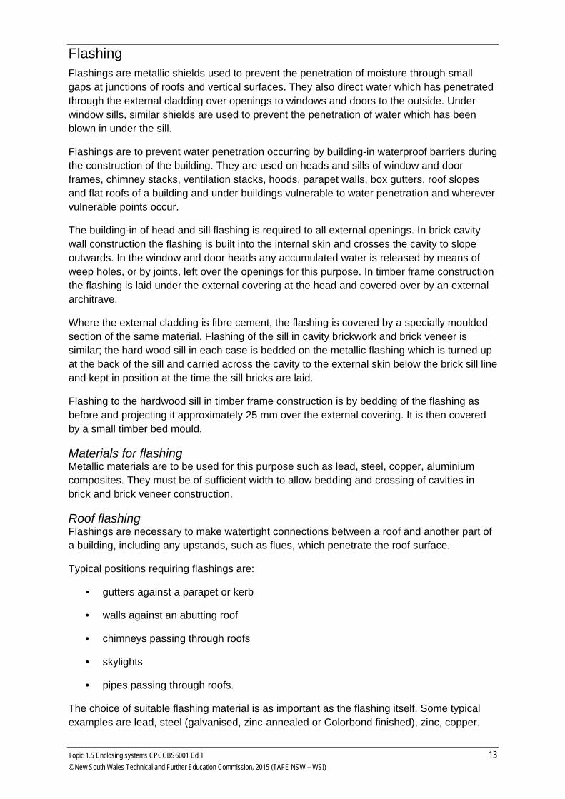
Note the flashing inserted into the brickwork wall above the abutting roof, ready to be folded down over the roof covering.
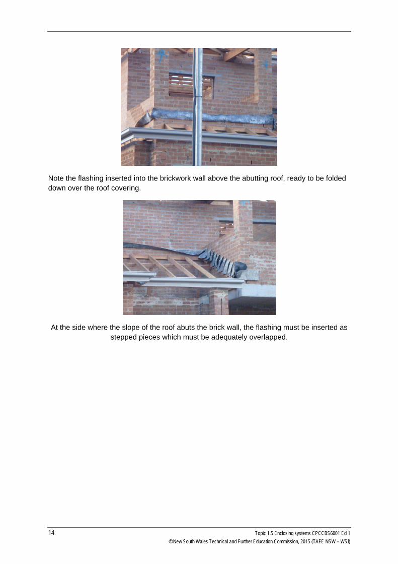
At the side where the slope of the roof abuts the brick wall, the flashing must be inserted as stepped pieces which must be adequately overlapped.
14 Topic 1.5 Enclosing systems CPCCBS6001 Ed 1 © New South Wales Technical and Further Education Commission, 2015 (TAFE NSW – WSI)
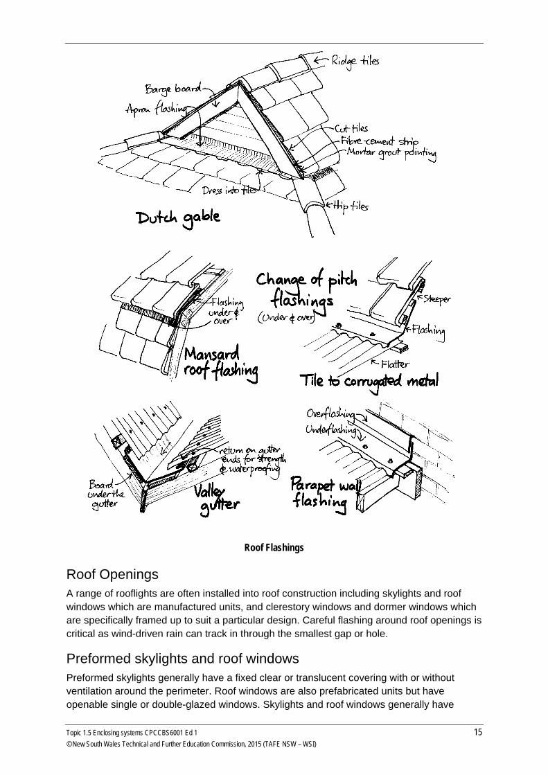
Roof Flashings
Roof Openings A range of rooflights are often installed into roof construction including skylights and roof windows which are manufactured units, and clerestory windows and dormer windows which are specifically framed up to suit a particular design. Careful flashing around roof openings is critical as wind-driven rain can track in through the smallest gap or hole.
Preformed skylights and roof windows Preformed skylights generally have a fixed clear or translucent covering with or without ventilation around the perimeter. Roof windows are also prefabricated units but have openable single or double-glazed windows. Skylights and roof windows generally have
Topic 1.5 Enclosing systems CPCCBS6001 Ed 1 15 © New South Wales Technical and Further Education Commission, 2015 (TAFE NSW – WSI)
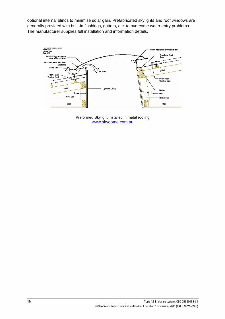
optional internal blinds to minimise solar gain. Prefabricated skylights and roof windows are generally provided with built-in flashings, gutters, etc. to overcome water entry problems. The manufacturer supplies full installation and information details.
Preformed Skylight installed in metal roofing www.skydome.com.au
16 Topic 1.5 Enclosing systems CPCCBS6001 Ed 1 © New South Wales Technical and Further Education Commission, 2015 (TAFE NSW – WSI)
Roof cladding The main function of a roof is to keep rain out. Points to watch are:
• Internal gutters must be adequately designed to prevent overflow.
• Downpipe blockage should not produce internal overflow.
• The amount of end lapping of tiles and the various sheeting materials should be determined by the slope or pitch of the roof. Sealing of laps in metal roofs retards oxidation considerably.
• Side lapping must be adequate and properly executed.
• Sarking is necessary for low-pitched and high-pitched tile roofs to prevent wind-driven rain from entering ceilings below.
• Adequate flashing is essential at parapets, chimneys and upstands through roofs.
• Avoidance of blow-back is essential under the ends of low pitch sheet roofs at the gutter. It is equally important to provide bird-proofing stops under large corrugation asbestos cement roofs.
• Roofing of all types should be installed in accordance with the manufacturer’s instructions. Many proprietary roofing materials are fixed by skilled tradesmen employed by the manufacturers, and are guaranteed for periods of twelve months or more.
• The adequate timbering of the roof structure is as important as the roof material. Timber shrinkage and sag will invariably cause roofing surfaces to fail, particularly in the case of tiled roofs where accurate seating and interlocking is essential for weatherproofing.
Tiles Roofing materials should, of course, be impervious to water, but some (such as burnt clay or terracotta tiles and asbestos cement) absorb quite a considerable amount of the initial stormwater. These materials have a textured surface and water will run off them more slowly than it will off smooth hard metal sheeting. Such characteristics are described by a ‘surface run-off factor’ which will be given later when we look at stormwater design.
Roof tiles are small units (the common concrete roof tile measures about 300 wide × 400 long) laid side by side with the bottom edge laid over the next tile down the slope. The side joins may be staggered down the slope or in line from ridge to eave depending on the profile used.
Roof tiles and forms can be made from:
• concrete - for various tile profiles and a flat ‘slate’ profiles
• traditional terra cotta tiles and variations such as a ‘half pipe’ profile
• slate and terracotta shingles
• timber shingles and shakes
Topic 1.5 Enclosing systems CPCCBS6001 Ed 1 17 © New South Wales Technical and Further Education Commission, 2015 (TAFE NSW – WSI)
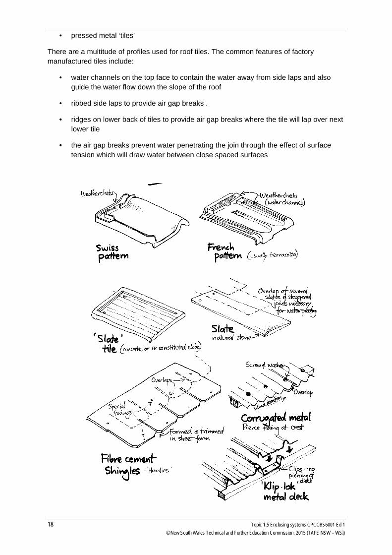
• pressed metal ‘tiles’
There are a multitude of profiles used for roof tiles. The common features of factory manufactured tiles include:
• water channels on the top face to contain the water away from side laps and also guide the water flow down the slope of the roof
• ribbed side laps to provide air gap breaks .
• ridges on lower back of tiles to provide air gap breaks where the tile will lap over next lower tile
• the air gap breaks prevent water penetrating the join through the effect of surface tension which will draw water between close spaced surfaces
18 Topic 1.5 Enclosing systems CPCCBS6001 Ed 1 © New South Wales Technical and Further Education Commission, 2015 (TAFE NSW – WSI)
Different Roof Cladding
Installation Roof tiles are laid separately (metal tiles usually in sheets covering many normal tile sizes) on battens spaced to pick up the top of the tile. Fixing of tiles depends on which area of Australia you are in and the type and profile of the tile.
In some locations every tile must be held to a batten with some form of fixing such as metal or wire clips, nails or screws. In other locations each second tile has to be fixed. You local supplier will provide details on the recommended fixing procedure and type of fixing to use.
Roof tiles should generally not be used on roof pitches less than 15° with some profiles not recommended on roof pitch less than 25°. Also roof tilers are generally paid extra for steep pitches (such as those over 30°) as tiles with a smooth surface are very slippery when moisture is present. This moisture may be caused by rain or morning dew.
Additional protection for tiled roofs Shingles and shakes are usually laid over a sub roof sheeting such as plywood. Manufactures of roof tiles recommend that roof sarking should always be installed prior to laying roof tiles as an added protection as a secondary protection against moisture penetration, especially due to wind action, and also condensation on the underside of the tile. The use of a reflective foil also helps exclude external heat in summer and impede the loss of internal heat in winter.
Sheet roofing Sheet roofing is made from metal sheets, usually 600 - 900mm wide, that have a water channelling profile formed in the sheet. The most common is corrugated galvanised iron (steel).
Sheet roofing for domestic use is made from:
• galvanised steel
• zincalume finished steel
• aluminium
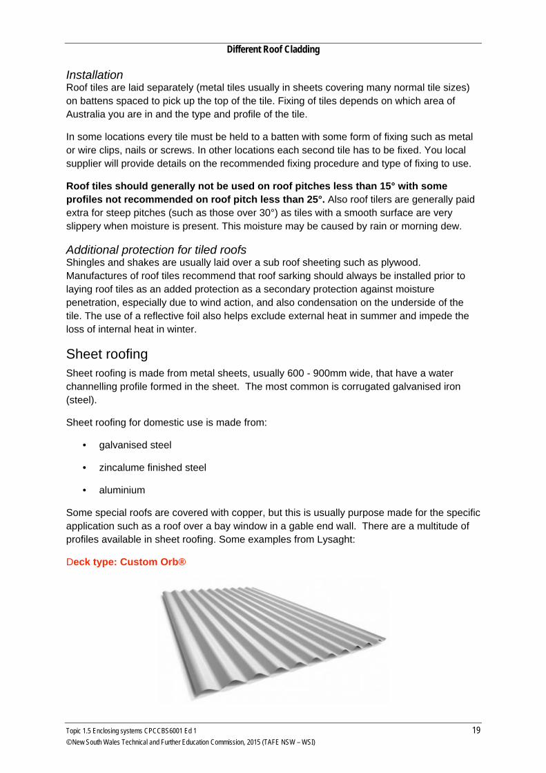
Some special roofs are covered with copper, but this is usually purpose made for the specific application such as a roof over a bay window in a gable end wall. There are a multitude of profiles available in sheet roofing. Some examples from Lysaght:
Deck type: Custom Orb®
Topic 1.5 Enclosing systems CPCCBS6001 Ed 1 19 © New South Wales Technical and Further Education Commission, 2015 (TAFE NSW – WSI)
Roof slope = 10° (1in 6)
Maximum run-off length of sheet (m) = 25
Roof slope = 5° (1 in 12)
Maximum run-off length of sheet (m) = 20
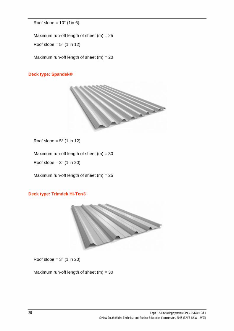
Deck type: Spandek®
Roof slope = 5° (1 in 12)
Maximum run-off length of sheet (m) = 30
Roof slope = 3° (1 in 20)
Maximum run-off length of sheet (m) = 25
Deck type: Trimdek Hi-Ten®
Roof slope = 3° (1 in 20)
Maximum run-off length of sheet (m) = 30
20 Topic 1.5 Enclosing systems CPCCBS6001 Ed 1 © New South Wales Technical and Further Education Commission, 2015 (TAFE NSW – WSI)
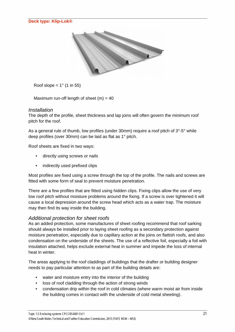
Deck type: Klip-Lok®
Roof slope = 1° (1 in 55)
Maximum run-off length of sheet (m) = 40
Installation The depth of the profile, sheet thickness and lap joins will often govern the minimum roof pitch for the roof.
As a general rule of thumb, low profiles (under 30mm) require a roof pitch of 3°-5° while deep profiles (over 30mm) can be laid as flat as 1° pitch.
Roof sheets are fixed in two ways:
• directly using screws or nails
• indirectly used prefixed clips
Most profiles are fixed using a screw through the top of the profile. The nails and screws are fitted with some form of seal to prevent moisture penetration.
There are a few profiles that are fitted using hidden clips. Fixing clips allow the use of very low roof pitch without moisture problems around the fixing. If a screw is over tightened it will cause a local depression around the screw head which acts as a water trap. The moisture may then find its way inside the building.
Additional protection for sheet roofs As an added protection, some manufactures of sheet roofing recommend that roof sarking should always be installed prior to laying sheet roofing as a secondary protection against moisture penetration, especially due to capillary action at the joins on flattish roofs, and also condensation on the underside of the sheets. The use of a reflective foil, especially a foil with insulation attached, helps exclude external heat in summer and impede the loss of internal heat in winter.
The areas applying to the roof claddings of buildings that the drafter or building designer needs to pay particular attention to as part of the building details are:
• water and moisture entry into the interior of the building • loss of roof cladding through the action of strong winds • condensation drip within the roof in cold climates (where warm moist air from inside
the building comes in contact with the underside of cold metal sheeting).
Topic 1.5 Enclosing systems CPCCBS6001 Ed 1 21 © New South Wales Technical and Further Education Commission, 2015 (TAFE NSW – WSI)
Some areas that need particular attention are:
• at changes of roof pitch as in a mansard roof • where the roof cladding meets vertical surfaces such as walls and dutch gables • edges of the roof at barges, gutters and valleys • valleys - especially on flat roofs or on roofs of differing pitches.
Translucent roofing materials Fibreglass, PVC or acrylic are often used in profiled sheet form to provide light within a roofed area. They are moulded to match the adjacent roofing material and are installed in much the same way.
Guttering and downpipes Rainwater falling on a roof may be allowed to:
• drain off the roof freely, without gutters or other devices
• be led to a gutter, where it flows to a downpipe, or
• be directed to roof-drainage device by means of slope in roof structure.
Various roof-drainage devices are available for different roof constructions and rainwater conditions. Whatever method is chosen, it is important to drain water from the roof as quickly as possible and avoid ponding or build-up by constriction of flow or obstruction.
Interruption to drainage flow can impose additional loading on a structure and cause extensive damage, such as ceiling collapse. As well, drainage systems can overflow, resulting in water damage within the building. Box gutters are notorious for overflowing and causing extensive internal damage. The design should include overflow drains to relieve water from the roof in the event of blockages or severe storms.
22 Topic 1.5 Enclosing systems CPCCBS6001 Ed 1 © New South Wales Technical and Further Education Commission, 2015 (TAFE NSW – WSI)
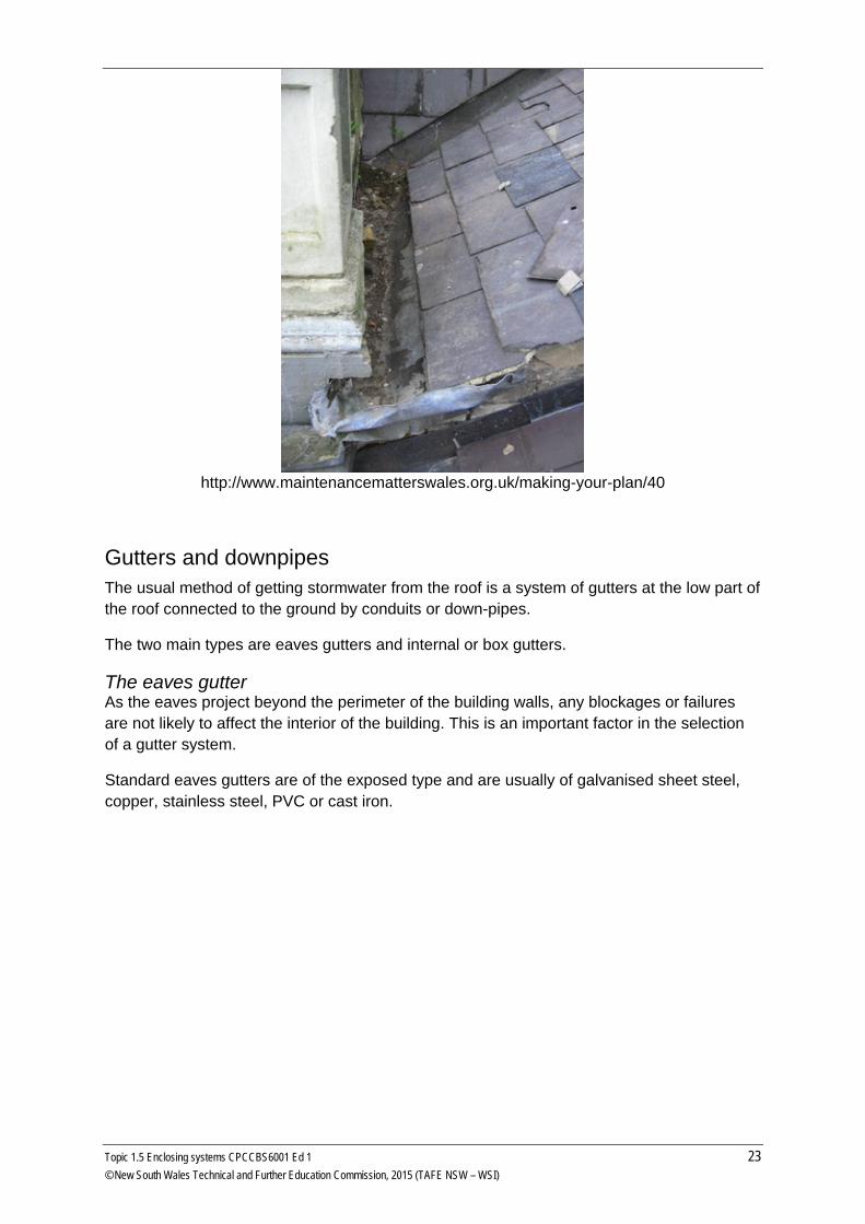
http://www.maintenancematterswales.org.uk/making-your-plan/40
Gutters and downpipes The usual method of getting stormwater from the roof is a system of gutters at the low part of the roof connected to the ground by conduits or down-pipes.
The two main types are eaves gutters and internal or box gutters.
The eaves gutter As the eaves project beyond the perimeter of the building walls, any blockages or failures are not likely to affect the interior of the building. This is an important factor in the selection of a gutter system.
Standard eaves gutters are of the exposed type and are usually of galvanised sheet steel, copper, stainless steel, PVC or cast iron.
Topic 1.5 Enclosing systems CPCCBS6001 Ed 1 23 © New South Wales Technical and Further Education Commission, 2015 (TAFE NSW – WSI)
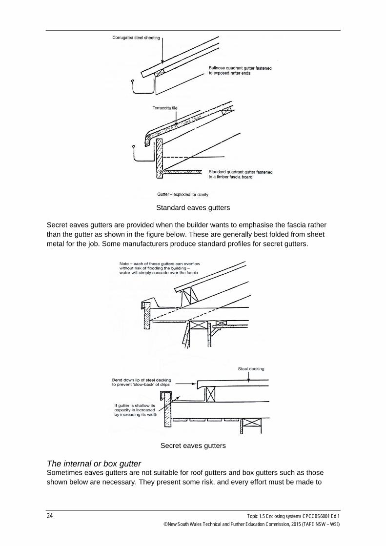
Standard eaves gutters
Secret eaves gutters are provided when the builder wants to emphasise the fascia rather than the gutter as shown in the figure below. These are generally best folded from sheet metal for the job. Some manufacturers produce standard profiles for secret gutters.
Secret eaves gutters
The internal or box gutter Sometimes eaves gutters are not suitable for roof gutters and box gutters such as those shown below are necessary. They present some risk, and every effort must be made to
24 Topic 1.5 Enclosing systems CPCCBS6001 Ed 1 © New South Wales Technical and Further Education Commission, 2015 (TAFE NSW – WSI)
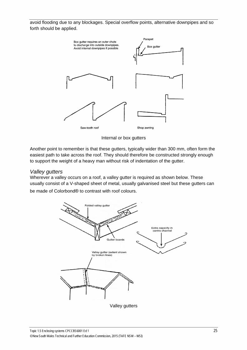
avoid flooding due to any blockages. Special overflow points, alternative downpipes and so forth should be applied.
Internal or box gutters
Another point to remember is that these gutters, typically wider than 300 mm, often form the easiest path to take across the roof. They should therefore be constructed strongly enough to support the weight of a heavy man without risk of indentation of the gutter.
Valley gutters Wherever a valley occurs on a roof, a valley gutter is required as shown below. These usually consist of a V-shaped sheet of metal, usually galvanised steel but these gutters can be made of Colorbond® to contrast with roof colours.
Valley gutters
Topic 1.5 Enclosing systems CPCCBS6001 Ed 1 25 © New South Wales Technical and Further Education Commission, 2015 (TAFE NSW – WSI)
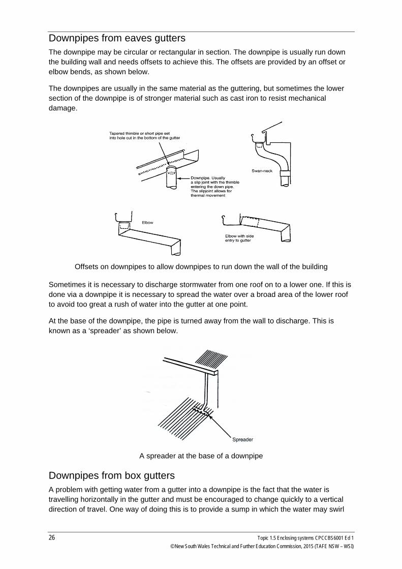
Downpipes from eaves gutters The downpipe may be circular or rectangular in section. The downpipe is usually run down the building wall and needs offsets to achieve this. The offsets are provided by an offset or elbow bends, as shown below.
The downpipes are usually in the same material as the guttering, but sometimes the lower section of the downpipe is of stronger material such as cast iron to resist mechanical damage.
Offsets on downpipes to allow downpipes to run down the wall of the building
Sometimes it is necessary to discharge stormwater from one roof on to a lower one. If this is done via a downpipe it is necessary to spread the water over a broad area of the lower roof to avoid too great a rush of water into the gutter at one point.
At the base of the downpipe, the pipe is turned away from the wall to discharge. This is known as a ‘spreader’ as shown below.
A spreader at the base of a downpipe
Downpipes from box gutters A problem with getting water from a gutter into a downpipe is the fact that the water is travelling horizontally in the gutter and must be encouraged to change quickly to a vertical direction of travel. One way of doing this is to provide a sump in which the water may swirl
26 Topic 1.5 Enclosing systems CPCCBS6001 Ed 1 © New South Wales Technical and Further Education Commission, 2015 (TAFE NSW – WSI)
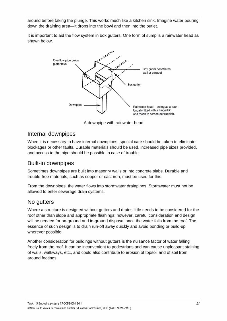
around before taking the plunge. This works much like a kitchen sink. Imagine water pouring down the draining area—it drops into the bowl and then into the outlet.
It is important to aid the flow system in box gutters. One form of sump is a rainwater head as shown below.
A downpipe with rainwater head
Internal downpipes When it is necessary to have internal downpipes, special care should be taken to eliminate blockages or other faults. Durable materials should be used, increased pipe sizes provided, and access to the pipe should be possible in case of trouble.
Built-in downpipes Sometimes downpipes are built into masonry walls or into concrete slabs. Durable and trouble-free materials, such as copper or cast iron, must be used for this.
From the downpipes, the water flows into stormwater drainpipes. Stormwater must not be allowed to enter sewerage drain systems.
No gutters Where a structure is designed without gutters and drains little needs to be considered for the roof other than slope and appropriate flashings; however, careful consideration and design will be needed for on-ground and in-ground disposal once the water falls from the roof. The essence of such design is to drain run-off away quickly and avoid ponding or build-up wherever possible.
Another consideration for buildings without gutters is the nuisance factor of water falling freely from the roof. It can be inconvenient to pedestrians and can cause unpleasant staining of walls, walkways, etc., and could also contribute to erosion of topsoil and of soil from around footings.
Topic 1.5 Enclosing systems CPCCBS6001 Ed 1 27 © New South Wales Technical and Further Education Commission, 2015 (TAFE NSW – WSI)
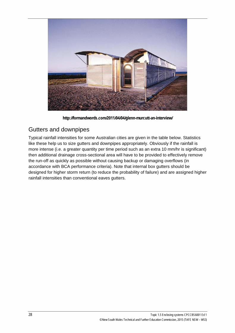
http://formandwords.com/2011/04/04/glenn-murcutt-an-interview/
Gutters and downpipes Typical rainfall intensities for some Australian cities are given in the table below. Statistics like these help us to size gutters and downpipes appropriately. Obviously if the rainfall is more intense (i.e. a greater quantity per time period such as an extra 10 mm/hr is significant) then additional drainage cross-sectional area will have to be provided to effectively remove the run-off as quickly as possible without causing backup or damaging overflows (in accordance with BCA performance criteria). Note that internal box gutters should be designed for higher storm return (to reduce the probability of failure) and are assigned higher rainfall intensities than conventional eaves gutters.
28 Topic 1.5 Enclosing systems CPCCBS6001 Ed 1 © New South Wales Technical and Further Education Commission, 2015 (TAFE NSW – WSI)
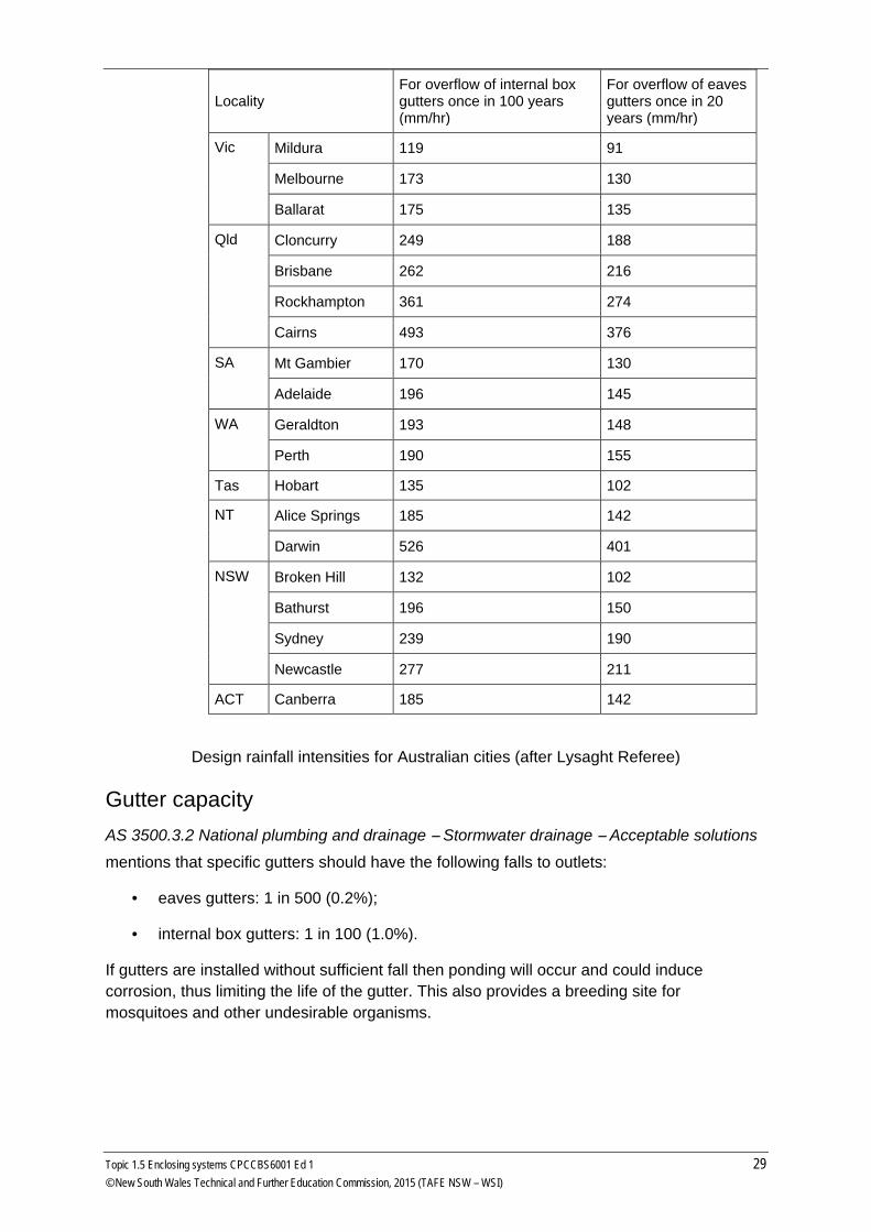
Locality For overflow of internal box gutters once in 100 years (mm/hr)
For overflow of eaves gutters once in 20 years (mm/hr)
Vic Mildura 119 91
Melbourne 173 130
Ballarat 175 135
Qld Cloncurry 249 188
Brisbane 262 216
Rockhampton 361 274
Cairns 493 376
SA Mt Gambier 170 130
Adelaide 196 145
WA Geraldton 193 148
Perth 190 155
Tas Hobart 135 102
NT Alice Springs 185 142
Darwin 526 401
NSW Broken Hill 132 102
Bathurst 196 150
Sydney 239 190
Newcastle 277 211
ACT Canberra 185 142
Design rainfall intensities for Australian cities (after Lysaght Referee)
Gutter capacity AS 3500.3.2 National plumbing and drainage – Stormwater drainage – Acceptable solutions
mentions that specific gutters should have the following falls to outlets:
• eaves gutters: 1 in 500 (0.2%);
• internal box gutters: 1 in 100 (1.0%).
If gutters are installed without sufficient fall then ponding will occur and could induce corrosion, thus limiting the life of the gutter. This also provides a breeding site for mosquitoes and other undesirable organisms.
Topic 1.5 Enclosing systems CPCCBS6001 Ed 1 29 © New South Wales Technical and Further Education Commission, 2015 (TAFE NSW – WSI)
http://www.hardwoodinstaller.com
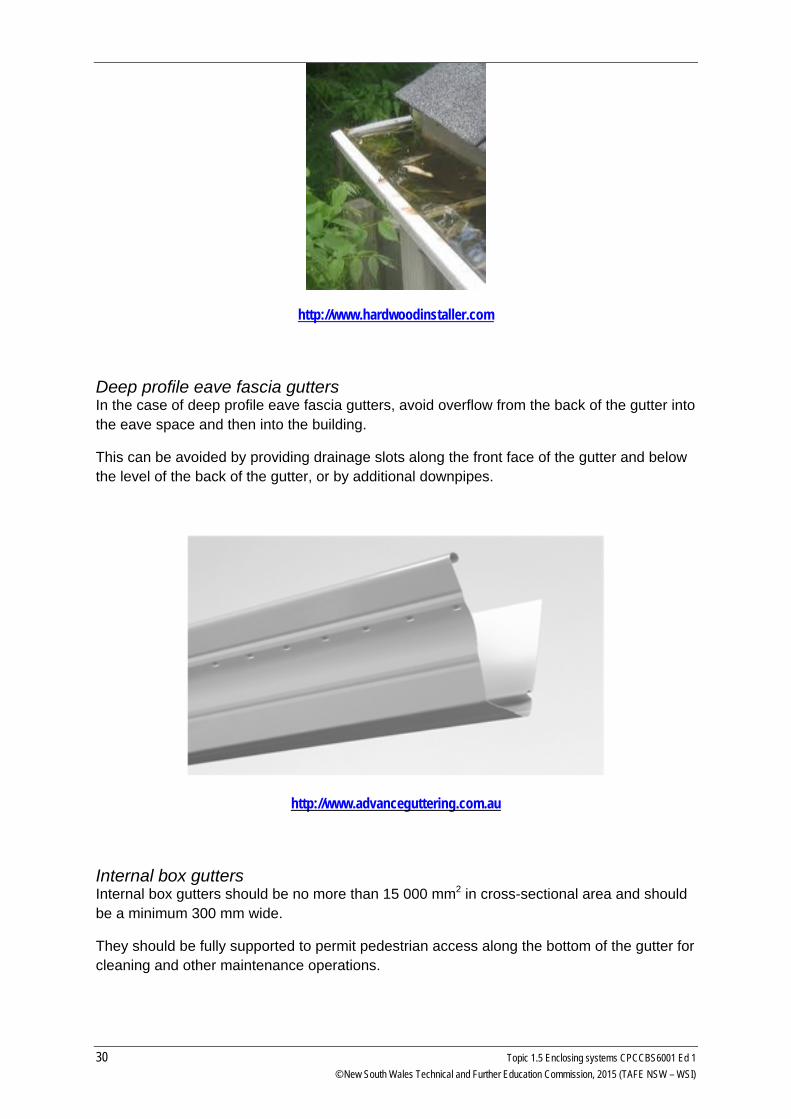
Deep profile eave fascia gutters In the case of deep profile eave fascia gutters, avoid overflow from the back of the gutter into the eave space and then into the building.
This can be avoided by providing drainage slots along the front face of the gutter and below the level of the back of the gutter, or by additional downpipes.
http://www.advanceguttering.com.au
Internal box gutters Internal box gutters should be no more than 15 000 mm2 in cross-sectional area and should be a minimum 300 mm wide.
They should be fully supported to permit pedestrian access along the bottom of the gutter for cleaning and other maintenance operations.
30 Topic 1.5 Enclosing systems CPCCBS6001 Ed 1 © New South Wales Technical and Further Education Commission, 2015 (TAFE NSW – WSI)
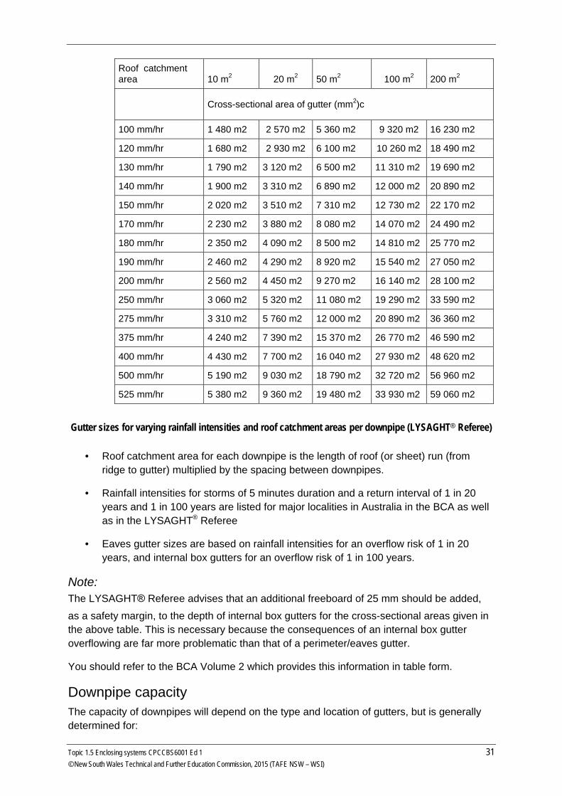
Roof catchment area 10 m2 20 m2 50 m2 100 m2 200 m2
Cross-sectional area of gutter (mm2)c
100 mm/hr 1 480 m2 2 570 m2 5 360 m2 9 320 m2 16 230 m2
120 mm/hr 1 680 m2 2 930 m2 6 100 m2 10 260 m2 18 490 m2
130 mm/hr 1 790 m2 3 120 m2 6 500 m2 11 310 m2 19 690 m2
140 mm/hr 1 900 m2 3 310 m2 6 890 m2 12 000 m2 20 890 m2
150 mm/hr 2 020 m2 3 510 m2 7 310 m2 12 730 m2 22 170 m2
170 mm/hr 2 230 m2 3 880 m2 8 080 m2 14 070 m2 24 490 m2
180 mm/hr 2 350 m2 4 090 m2 8 500 m2 14 810 m2 25 770 m2
190 mm/hr 2 460 m2 4 290 m2 8 920 m2 15 540 m2 27 050 m2
200 mm/hr 2 560 m2 4 450 m2 9 270 m2 16 140 m2 28 100 m2
250 mm/hr 3 060 m2 5 320 m2 11 080 m2 19 290 m2 33 590 m2
275 mm/hr 3 310 m2 5 760 m2 12 000 m2 20 890 m2 36 360 m2
375 mm/hr 4 240 m2 7 390 m2 15 370 m2 26 770 m2 46 590 m2
400 mm/hr 4 430 m2 7 700 m2 16 040 m2 27 930 m2 48 620 m2
500 mm/hr 5 190 m2 9 030 m2 18 790 m2 32 720 m2 56 960 m2
525 mm/hr 5 380 m2 9 360 m2 19 480 m2 33 930 m2 59 060 m2
Gutter sizes for varying rainfall intensities and roof catchment areas per downpipe (LYSAGHT® Referee)
• Roof catchment area for each downpipe is the length of roof (or sheet) run (from ridge to gutter) multiplied by the spacing between downpipes.
• Rainfall intensities for storms of 5 minutes duration and a return interval of 1 in 20 years and 1 in 100 years are listed for major localities in Australia in the BCA as well as in the LYSAGHT® Referee
• Eaves gutter sizes are based on rainfall intensities for an overflow risk of 1 in 20 years, and internal box gutters for an overflow risk of 1 in 100 years.
Note: The LYSAGHT® Referee advises that an additional freeboard of 25 mm should be added,
as a safety margin, to the depth of internal box gutters for the cross-sectional areas given in the above table. This is necessary because the consequences of an internal box gutter overflowing are far more problematic than that of a perimeter/eaves gutter.
You should refer to the BCA Volume 2 which provides this information in table form.
Downpipe capacity The capacity of downpipes will depend on the type and location of gutters, but is generally determined for:
Topic 1.5 Enclosing systems CPCCBS6001 Ed 1 31 © New South Wales Technical and Further Education Commission, 2015 (TAFE NSW – WSI)
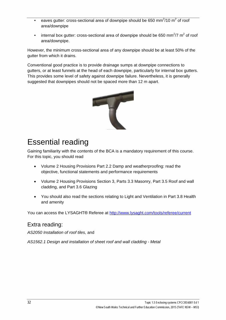
• eaves gutter: cross-sectional area of downpipe should be 650 mm2/10 m2 of roof
area/downpipe
• internal box gutter: cross-sectional area of downpipe should be 650 mm2/7 m2 of roof area/downpipe.
However, the minimum cross-sectional area of any downpipe should be at least 50% of the gutter from which it drains.
Conventional good practice is to provide drainage sumps at downpipe connections to gutters, or at least funnels at the head of each downpipe, particularly for internal box gutters. This provides some level of safety against downpipe failure. Nevertheless, it is generally suggested that downpipes should not be spaced more than 12 m apart.
Essential reading Gaining familiarity with the contents of the BCA is a mandatory requirement of this course. For this topic, you should read
• Volume 2 Housing Provisions Part 2.2 Damp and weatherproofing: read the objective, functional statements and performance requirements
• Volume 2 Housing Provisions Section 3, Parts 3.3 Masonry, Part 3.5 Roof and wall cladding, and Part 3.6 Glazing
• You should also read the sections relating to Light and Ventilation in Part 3.8 Health and amenity
You can access the LYSAGHT® Referee at http://www.lysaght.com/tools/referee/current
Extra reading: AS2050 Installation of roof tiles, and
AS1562.1 Design and installation of sheet roof and wall cladding - Metal
32 Topic 1.5 Enclosing systems CPCCBS6001 Ed 1 © New South Wales Technical and Further Education Commission, 2015 (TAFE NSW – WSI)
Glazing BCA Requirements Part 3.6 of the BCA Volume 2 covers the requirements for glazing including windows. Performance requirements P2.1.1 and P2.2.2 are satisfied for glazing and windows if designed and constructed in accordance with AS 2047 Windows and external doors in buildings for certain windows, sliding doors with a frame, adjustable louvres and window walls with one piece framing. Performance requirement P2.1.1 is satisfied for glazing if designed and constructed in accordance with AS1288 Glass in buildings – Selection and installation for all glazed assemblies not covered by the above (BCA, Part 3.6.0 (a)) and the following glazed assemblies:
i. All glazed assemblies not in an external wall ii. Revolving doors iii. Fixed louvres iv. Skylights and the like v. Sliding doors without a frame vi. Windows constructed on site vii. Second hand windows and the like
viii. Heritage windows ix. Glazing used in balustrades and sloping overhead glazing
Acceptable construction practices for windows and glazing are specified in parts 3.6.1 to 3.6.4. You should spend some time reading and becoming familiar with this part of the BCA.
Windows A window is a glazed opening in a wall. Its function is to admit light and air, exclude rain and wind, to conserve the heat within the building or to prevent its penetration. Glass is set in timber or metal sashes or frames. Sashes can either be fixed in position or made to open in various ways for ventilation. A window consists of a frame containing glass panels. The glass is sealed in the frame to prevent water penetration. Window frames are generally made from timber, aluminium and occasionally steel. The join between the frame and the cladding provides a point of entry for moisture and requires careful detailing. To provide a weather seal between the window frame and the cladding, a damp proof membrane (or flashing) is generally used to act as a moisture barrier. Information on the recommended installation of windows is available from the window supplier. In most cases the windows can be supplied with flashings already fixed to the frame. Another consideration when fitting doors and windows is to leave expansion and contraction joints when fitting different materials together which expand and contract at different rates.
Topic 1.5 Enclosing systems CPCCBS6001 Ed 1 33 © New South Wales Technical and Further Education Commission, 2015 (TAFE NSW – WSI)
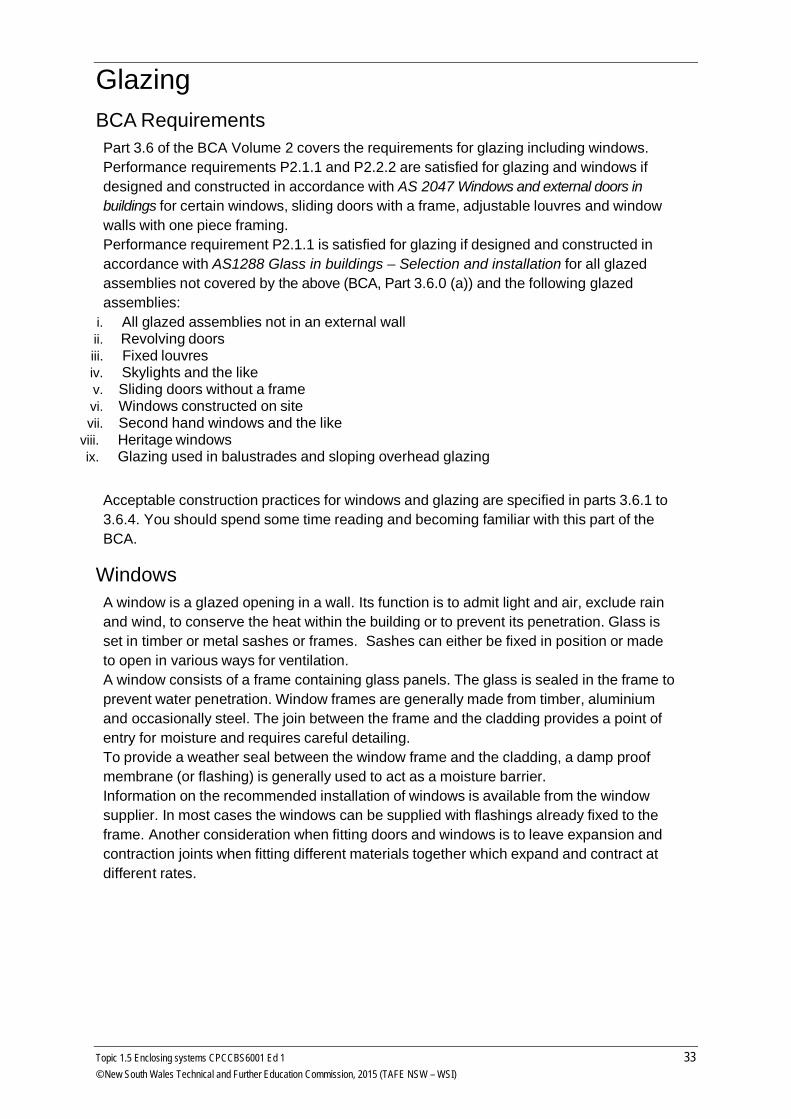
Typical window detail for cavity brick installation
This diagram shows a detail of window joinery in a cavity brick wall. Flashing is very important in stopping moisture from entering the dwelling and the position of flashing needs to be correct. Flashing in wall openings must be installed in accordance with Parts 3.5.3.6 and 3.3.4.5 of the BCA using materials that comply with AS/NZS 2904.
34 Topic 1.5 Enclosing systems CPCCBS6001 Ed 1 © New South Wales Technical and Further Education Commission, 2015 (TAFE NSW – WSI)
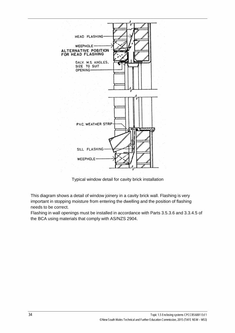
Typical window flashing detail for a timber framed, clad building.
Typical window joinery in brick veneer and timber frame.
Topic 1.5 Enclosing systems CPCCBS6001 Ed 1 35 © New South Wales Technical and Further Education Commission, 2015 (TAFE NSW – WSI)
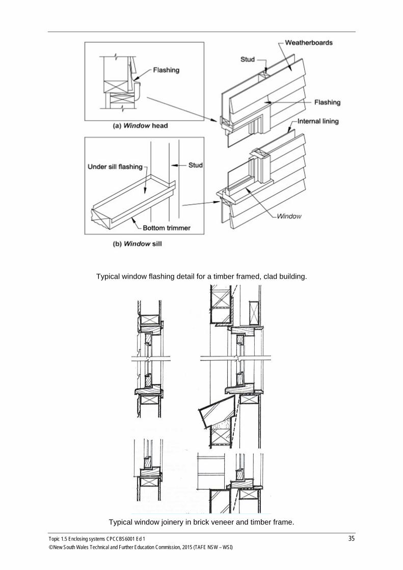
Common Window Sash Types A sash is the inner frame of a window in which the glass is fixed. They are either fixed, or hung in the outer frames and named accordingly. Common sash types include:
• Fixed Light - Frame may be either timber or aluminium. • Horizontal sliding - The frame is generally in aluminium and produced in
standard sizes. • Top hung swing - Frame is generally in timber, and are massed produced in
standard sizes. • Side hung casement - Frame generally in timber and purpose made. • Double hung - Frame traditionally in timber, but now often aluminium.
Generally purpose made, but there are some standard ranges. Use counterbalancing systems including traditional lead weights and spiral friction balances.
• Louvre - Frame in aluminium, steel or timber and generally purpose made. Generally fixed to a timber sub frame.
• Bottom hung hopper - Frame generally timber and are purpose made. Seldom used these days as it is difficult to get 100% water tightness.
Doors Doors are used both inside and outside of the building and have many functions, such as:
• Keeping out the elements
• Providing security
• Closing openings between internal spaces
• Restricting the spread of fire
The design of a door is governed by its purpose and its position in the building, and it is for this reason that the various types used differ in construction.
Different Types of Door Ledged doors – are made by nailing sheeting (e.g. boards) to ledges. This is the simplest type of door, and is used mainly for sheds and out buildings and the like. Ledged and braced door - similar to ledged door but having braces cut in between the ledges on the diagonal to prevent at closing edge. Framed and panelled door - made in a variety of designs and usually named for the number of panels in the design (i.e. four panelled door). The panels are fitted into grooves in the inner edges of framing and must be finished with either ‘raised’ or flat mouldings, mitred around the frame and nailed into position. Flush doors - which include
• Hollow Core - Consists of a framed core of stiles with five or six intermediate rails and sheeted both sides with hardboard or plywood.
• Honeycomb - made with external frame 35 mm wide with sheeted both sides with hardboard or plywood and an internal infill of Kraft paper in the form of honeycomb cells.
• Solid core - constructed having a solid core of a number of pieces of narrow section glued together, to which is glued on each face a cross band and then a veneered face.
36 Topic 1.5 Enclosing systems CPCCBS6001 Ed 1 © New South Wales Technical and Further Education Commission, 2015 (TAFE NSW – WSI)
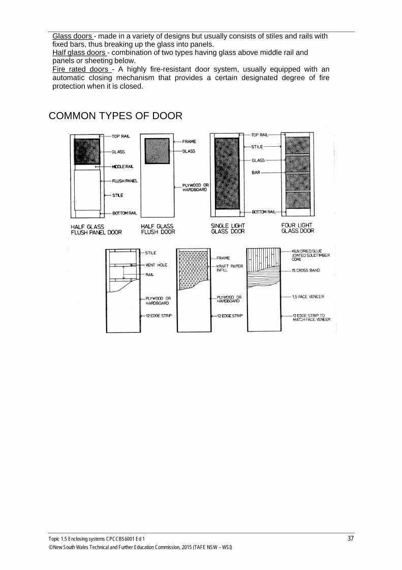
Glass doors - made in a variety of designs but usually consists of stiles and rails with fixed bars, thus breaking up the glass into panels. Half glass doors - combination of two types having glass above middle rail and panels or sheeting below. Fire rated doors - A highly fire-resistant door system, usually equipped with an automatic closing mechanism that provides a certain designated degree of fire protection when it is closed.
COMMON TYPES OF DOOR
Topic 1.5 Enclosing systems CPCCBS6001 Ed 1 37 © New South Wales Technical and Further Education Commission, 2015 (TAFE NSW – WSI)
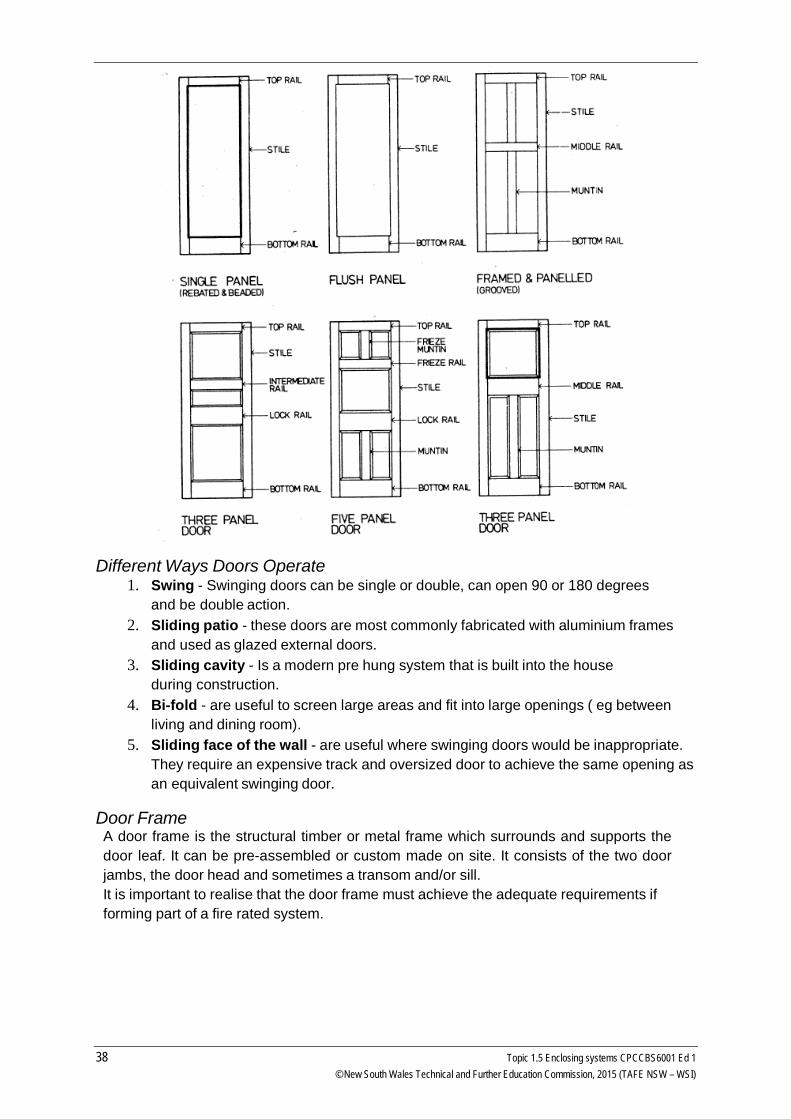
Different Ways Doors Operate 1. Swing - Swinging doors can be single or double, can open 90 or 180 degrees
and be double action. 2. Sliding patio - these doors are most commonly fabricated with aluminium frames
and used as glazed external doors. 3. Sliding cavity - Is a modern pre hung system that is built into the house
during construction. 4. Bi-fold - are useful to screen large areas and fit into large openings ( eg between
living and dining room). 5. Sliding face of the wall - are useful where swinging doors would be inappropriate.
They require an expensive track and oversized door to achieve the same opening as an equivalent swinging door.
Door Frame A door frame is the structural timber or metal frame which surrounds and supports the door leaf. It can be pre-assembled or custom made on site. It consists of the two door jambs, the door head and sometimes a transom and/or sill. It is important to realise that the door frame must achieve the adequate requirements if forming part of a fire rated system.
38 Topic 1.5 Enclosing systems CPCCBS6001 Ed 1 © New South Wales Technical and Further Education Commission, 2015 (TAFE NSW – WSI)
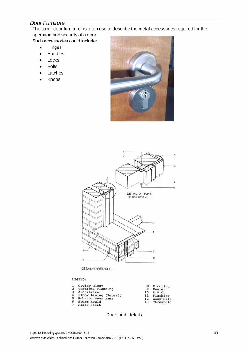
Door Furniture The term "door furniture" is often use to describe the metal accessories required for the operation and security of a door. Such accessories could include:
• Hinges • Handles • Locks • Bolts • Latches • Knobs
Door jamb details
Topic 1.5 Enclosing systems CPCCBS6001 Ed 1 39 © New South Wales Technical and Further Education Commission, 2015 (TAFE NSW – WSI)
Glass in doors is covered in Part 3.6.4.1 of the BCA Volume 2. Other glazing requirements to satisfy the performance requirements are covered in Part 3.6.
Additional reading http://www.yourhome.gov.au/passive-design/glazing has some excellent information on glazing and thermal performance as well as compliance issues and standards required for design of glazing in residential applications.
Read the following sections from Building Your Own Home:
• Topic 36 Brick veneer construction
• Topic 38 Powerpanel®
• Topic 39 Sheet and board claddings • Topic 40 Sheet and board products • Topic 43 Windows • Topic 44 Doors • Topic 49 Roof tiles • Topic 50 Roof sheets • Topic 52 Special roof details
The Australian House Building Manual, by Allan Staines, has some excellent drawings and information. Borrow a copy from your library and read:
• Page 94, Flashings • Chapter 6 Finishing, pages 95-99 and 101-102
40 Topic 1.5 Enclosing systems CPCCBS6001 Ed 1 © New South Wales Technical and Further Education Commission, 2015 (TAFE NSW – WSI)