enabling unassisted solar water splitting by iron...
TRANSCRIPT
ARTICLE
Received 20 Mar 2015 | Accepted 8 May 2015 | Published 16 Jun 2015
Enabling unassisted solar water splittingby iron oxide and siliconJi-Wook Jang1, Chun Du1, Yifan Ye2,3, Yongjing Lin4, Xiahui Yao1, James Thorne1, Erik Liu1, Gregory McMahon1,
Junfa Zhu3, Ali Javey4, Jinghua Guo2 & Dunwei Wang1
Photoelectrochemical (PEC) water splitting promises a solution to the problem of large-scale
solar energy storage. However, its development has been impeded by the poor performance
of photoanodes, particularly in their capability for photovoltage generation. Many examples
employing photovoltaic modules to correct the deficiency for unassisted solar water splitting
have been reported to-date. Here we show that, by using the prototypical photoanode
material of haematite as a study tool, structural disorders on or near the surfaces are
important causes of the low photovoltages. We develop a facile re-growth strategy to reduce
surface disorders and as a consequence, a turn-on voltage of 0.45 V (versus reversible
hydrogen electrode) is achieved. This result permits us to construct a photoelectrochemical
device with a haematite photoanode and Si photocathode to split water at an overall
efficiency of 0.91%, with NiFeOx and TiO2/Pt overlayers, respectively.
DOI: 10.1038/ncomms8447 OPEN
1 Department of Chemistry, Merkert Chemistry Center, Boston College, 2609 Beacon St, Chestnut Hill, Massachusetts 02467, USA. 2 Advanced Light Source,Lawrence Berkeley National Laboratory, Berkeley, California 94720, USA. 3 National Synchrotron Radiation Laboratory, University of Science and Technologyof China, Hefei 230029, China. 4 Department of Electrical Engineering and Computer Sciences and the Joint Center for Artificial Synthesis, University ofCalifornia, Berkeley, California 94720, USA. Correspondence and requests for materials should be addressed to D.W. (email: [email protected]).
NATURE COMMUNICATIONS | 6:7447 | DOI: 10.1038/ncomms8447 | www.nature.com/naturecommunications 1
& 2015 Macmillan Publishers Limited. All rights reserved.
How to carry out solar water splitting (H2O - ½ O2þreactive protons) efficiently and inexpensively constitutesa great challenge that inspires significant research1–3.
More efficient and stable than molecular systems and lessexpensive than simple combinations of photovoltaics andelectrolysis, direct photolysis (or photoelectrochemistry, PEC)is particularly appealing4. Decades of intense researchnotwithstanding, complete solar water splitting by PEC withoutthe need for externally applied bias (referred to as unassistedwater splitting) remains rare5–12. Existing examples often include,sometimes entirely powered by, photovoltaic modules5–10.The poor performance of photoanodes, especially in theirphotovoltage generation capabilities, has been a key issue. Thechallenges involved are probably best exemplified by haematite(a-Fe2O3), a prototypical photoanode material that has piquedgreat interest but failed to deliver the expected performance13–16.The most pronounced disadvantage that plagues the promisesheld by haematite is its low photovoltages, characterized bylate turn-ons in its photoelectrochemical behaviours (typically0.8–1.0 V). For a semiconductor whose reported Fermi levelranges between 0.4 and 0.7 V (versus reversible hydrogenelectrode (RHE)), the late turn-on voltages are not fullyaccounted for and require further understandings.
The light-to-charge conversion of a PEC device is governed bythe same photophysics that describes photovoltaics17. Theintricacy of how the semiconductor/water interface influencesboth the energetics and kinetics of a photoelectrode, however,makes it difficult to pinpoint the origins of potential loss at theinterface18–20. This is because both energetics (in the form ofphotovoltages) and kinetics (in the form of overpotentials) affectthe steady-state current/voltage behaviours in similar manners.The complexity has led to a recent debate on the role ofsurface modifications on haematite by cobalt phosphate-derivedamorphous layers21–24. On a parallel system featuring amorphousNiFeOx, prepared by a photochemical deposition technique25,we showed that significant cathodic shift enabled by the wateroxidation catalyst is primarily due to improvement in theinterface energetics, but not the water oxidation kinetics,despite the fact that NiFeOx is indeed a good water oxidationcatalyst20. Inspired by the understandings, here we seek to exploitwhat can be enabled by surface modifications. It is shown that afacile regrowth strategy readily improves the measuredphotovoltages on a haematite photoanode. Our results point the
origin of the low photovoltages towards short-range structuraldisorders near the surface of photoanode. A low turn-on voltageof 0.45 (±0.01) V was obtained, enabling unassisted watersplitting with amorphous Si as a photocathode26 at efficienciesup to 0.9%. Our demonstration represents the first example ofunassisted solar water splitting using haematite and Si as the solelight absorbers.
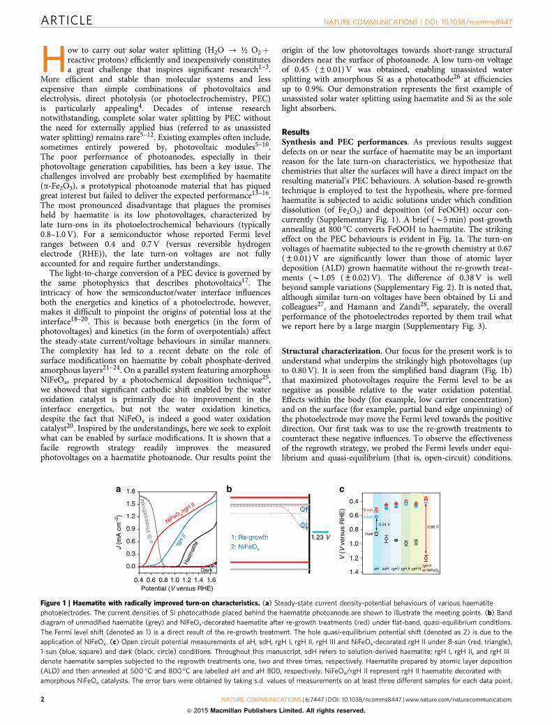
ResultsSynthesis and PEC performances. As previous results suggestdefects on or near the surface of haematite may be an importantreason for the late turn-on characteristics, we hypothesize thatchemistries that alter the surfaces will have a direct impact on theresulting material’s PEC behaviours. A solution-based re-growthtechnique is employed to test the hypothesis, where pre-formedhaematite is subjected to acidic solutions under which conditiondissolution (of Fe2O3) and deposition (of FeOOH) occur con-currently (Supplementary Fig. 1). A brief (B5 min) post-growthannealing at 800 �C converts FeOOH to haematite. The strikingeffect on the PEC behaviours is evident in Fig. 1a. The turn-onvoltages of haematite subjected to the re-growth chemistry at 0.67(±0.01) V are significantly lower than those of atomic layerdeposition (ALD) grown haematite without the re-growth treat-ments (B1.05 (±0.02) V). The difference of 0.38 V is wellbeyond sample variations (Supplementary Fig. 2). It is noted that,although similar turn-on voltages have been obtained by Li andcolleagues27, and Hamann and Zandi28, separately, the overallperformance of the photoelectrodes reported by them trail whatwe report here by a large margin (Supplementary Fig. 3).
Structural characterization. Our focus for the present work is tounderstand what underpins the strikingly high photovoltages (upto 0.80 V). It is seen from the simplified band diagram (Fig. 1b)that maximized photovoltages require the Fermi level to be asnegative as possible relative to the water oxidation potential.Effects within the body (for example, low carrier concentration)and on the surface (for example, partial band edge unpinning) ofthe photoelectrode may move the Fermi level towards the positivedirection. Our first task was to use the re-growth treatments tocounteract these negative influences. To observe the effectivenessof the regrowth strategy, we probed the Fermi levels under equi-librium and quasi-equilibrium (that is, open-circuit) conditions.
1
2
1: Re-growth
2: NiFeOx
b
1.4
1.2
1.0
0.8
0.6
0.48 sun
1 sun
V (
V v
ersu
s R
HE
)
Dark
aH sdH rgH I rgH II rgH IIIrgH IIw/ NiFeOx
0.24 V0.80 V
c
1.23 V
0.4 0.6 0.8 1.0 1.2 1.4 1.6
0.0
0.3
0.6
0.9
1.2
1.5
1.8
a-S
i Pho
toca
thod
e
Dark
Hae
mat
itergH II
NiFeO x/rg
H II
J (m
A c
m–2
)
Potential (V versus RHE)
a
Figure 1 | Haematite with radically improved turn-on characteristics. (a) Steady-state current density-potential behaviours of various haematite
photoelectrodes. The current densities of Si photocathode placed behind the haematite photoanode are shown to illustrate the meeting points. (b) Band
diagram of unmodified haematite (grey) and NiFeOx-decorated haematite after re-growth treatments (red) under flat-band, quasi-equilibrium conditions.
The Fermi level shift (denoted as 1) is a direct result of the re-growth treatment. The hole quasi-equilibrium potential shift (denoted as 2) is due to the
application of NiFeOx. (c) Open circuit potential measurements of aH, sdH, rgH I, rgH II, rgH III and NiFeOx-decorated rgH II under 8-sun (red, triangle),
1-sun (blue, square) and dark (black, circle) conditions. Throughout this manuscript, sdH refers to solution-derived haematite; rgH I, rgH II, and rgH III
denote haematite samples subjected to the regrowth treatments one, two and three times, respectively. Haematite prepared by atomic layer deposition
(ALD) and then annealed at 500 �C and 800 �C are labelled aH and aH 800, respectively. NiFeOx/rgH II represent rgH II haematite decorated with
amorphous NiFeOx catalysts. The error bars were obtained by taking s.d. values of measurements on at least three different samples for each data point.
ARTICLE NATURE COMMUNICATIONS | DOI: 10.1038/ncomms8447
2 NATURE COMMUNICATIONS | 6:7447 | DOI: 10.1038/ncomms8447 | www.nature.com/naturecommunications
& 2015 Macmillan Publishers Limited. All rights reserved.
The results are compared in Fig. 1c. The data under intense lightreport on potentials close to the ‘true’ flatband potential(Supplementary Fig. 4), whereas the potentials under 1-suncondition offer a reference point for us to understand the PECbehaviours as shown in Fig. 1a, which were taken under 1-sunillumination. The potentials in dark can be used to inspectwhether there are undesired surface Fermi level pinning effects.Examinations of Fig. 1c revealed that B0.13 V potential isharvested from the Fermi level shift due to the switch of synthesismethods (Vf¼ 0.62 (±0.01) V for ALD haematite, denoted as aHin Fig. 1c; Vf¼ 0.49 (±0.01) V for solution derived haematite,denoted as sdH). The difference in Vf is ascribed to the differencein the detailed structures of haematite prepared by variousmethods, as evidenced by the X-ray diffraction patterns (Fig. 2a).
It is hypothesized that during re-growth, nanoscale structureson the surface of haematite as a result of the FeOOH-Fe2O3
conversion are dissolved, and the newly grown structures favourthe o1104 directions. That increased (110)/(104) peak intensityratios (from 0.64 for aH to 10.1 for rgH II, SupplementaryTable 1) correspond to more negative Vf is consistent with theobservations made by Peter et al.29, on haematite synthesized bygas-phase pyrolysis. Consecutive re-growth treatments move Vf
towards the negative direction monotonically, reaching 0.44(±0.02) V after the second re-growth. Interestingly, thecorresponding dark equilibrium potentials also changemonotonically, towards the more positive position, reaching0.99 (±0.03) V after the second re-growth. Together, the simpletreatments increased the photovoltage (as measured by thedifference of Vf in light and in dark) by 27% (from 0.44 to 0.56 V).As the re-growth treatments are only expected to alter thesurfaces, changes in Fermi levels described here are ascribed tochanges in surface structures (Fig. 1c). Finally, the shift of Vf indark from 0.99 V to 1.21(±0.04) V upon the application ofNiFeOx is consistent with our previous observations20. The shiftof Vf under illumination from 0.44 V to 0.40 (±0.02) V, althoughmodest, is unexpected. We understand it as a result of improvedsurfaces by the application of NiFeOx. The final photovoltage of0.80 V is the highest for haematite reported in the literature.
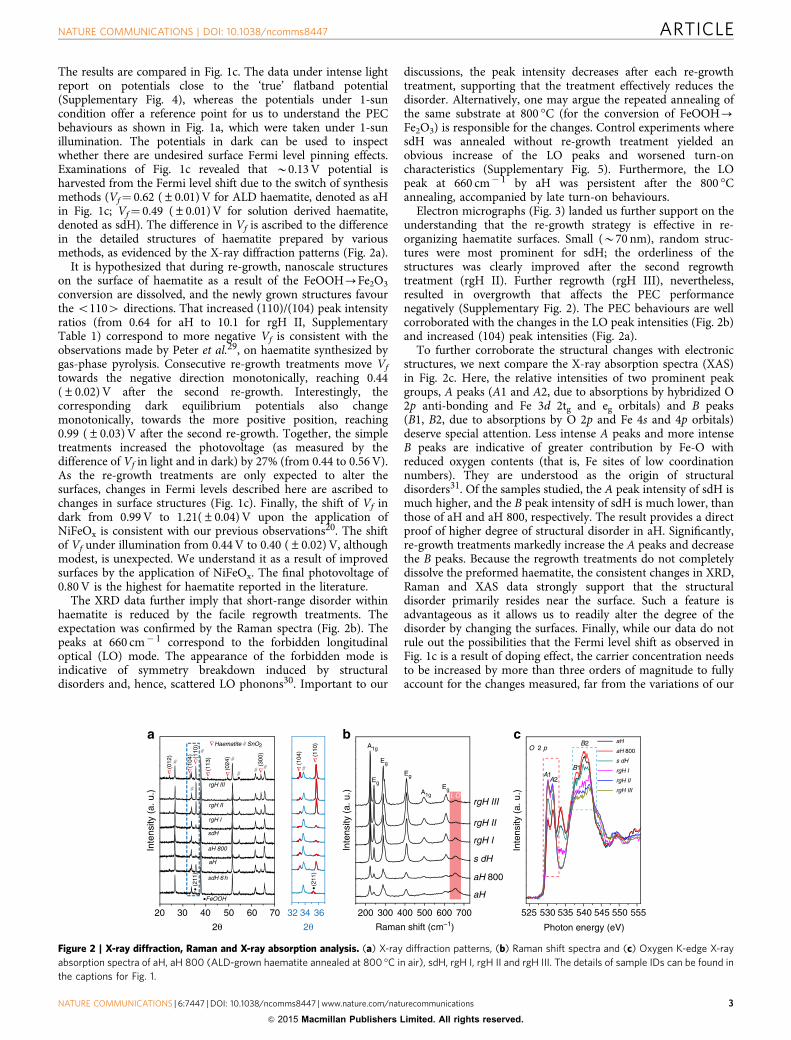
The XRD data further imply that short-range disorder withinhaematite is reduced by the facile regrowth treatments. Theexpectation was confirmed by the Raman spectra (Fig. 2b). Thepeaks at 660 cm� 1 correspond to the forbidden longitudinaloptical (LO) mode. The appearance of the forbidden mode isindicative of symmetry breakdown induced by structuraldisorders and, hence, scattered LO phonons30. Important to our
discussions, the peak intensity decreases after each re-growthtreatment, supporting that the treatment effectively reduces thedisorder. Alternatively, one may argue the repeated annealing ofthe same substrate at 800 �C (for the conversion of FeOOH-Fe2O3) is responsible for the changes. Control experiments wheresdH was annealed without re-growth treatment yielded anobvious increase of the LO peaks and worsened turn-oncharacteristics (Supplementary Fig. 5). Furthermore, the LOpeak at 660 cm� 1 by aH was persistent after the 800 �Cannealing, accompanied by late turn-on behaviours.
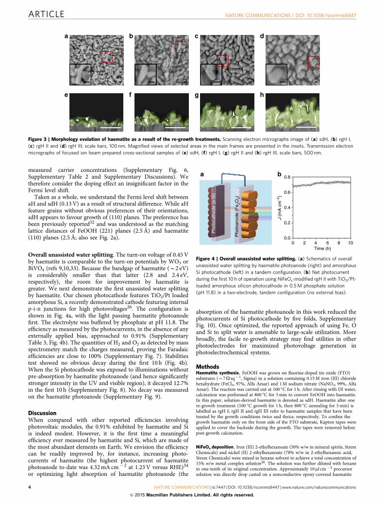
Electron micrographs (Fig. 3) landed us further support on theunderstanding that the re-growth strategy is effective in re-organizing haematite surfaces. Small (B70 nm), random struc-tures were most prominent for sdH; the orderliness of thestructures was clearly improved after the second regrowthtreatment (rgH II). Further regrowth (rgH III), nevertheless,resulted in overgrowth that affects the PEC performancenegatively (Supplementary Fig. 2). The PEC behaviours are wellcorroborated with the changes in the LO peak intensities (Fig. 2b)and increased (104) peak intensities (Fig. 2a).
To further corroborate the structural changes with electronicstructures, we next compare the X-ray absorption spectra (XAS)in Fig. 2c. Here, the relative intensities of two prominent peakgroups, A peaks (A1 and A2, due to absorptions by hybridized O2p anti-bonding and Fe 3d 2tg and eg orbitals) and B peaks(B1, B2, due to absorptions by O 2p and Fe 4s and 4p orbitals)deserve special attention. Less intense A peaks and more intenseB peaks are indicative of greater contribution by Fe-O withreduced oxygen contents (that is, Fe sites of low coordinationnumbers). They are understood as the origin of structuraldisorders31. Of the samples studied, the A peak intensity of sdH ismuch higher, and the B peak intensity of sdH is much lower, thanthose of aH and aH 800, respectively. The result provides a directproof of higher degree of structural disorder in aH. Significantly,re-growth treatments markedly increase the A peaks and decreasethe B peaks. Because the regrowth treatments do not completelydissolve the preformed haematite, the consistent changes in XRD,Raman and XAS data strongly support that the structuraldisorder primarily resides near the surface. Such a feature isadvantageous as it allows us to readily alter the degree of thedisorder by changing the surfaces. Finally, while our data do notrule out the possibilities that the Fermi level shift as observed inFig. 1c is a result of doping effect, the carrier concentration needsto be increased by more than three orders of magnitude to fullyaccount for the changes measured, far from the variations of our
525 530 535 540 545 550 555
O 2 paH
aH 800
s dH
rgH I
rgH II
rgH III
Inte
nsity
(a.
u.)
Photon energy (eV)
B2
B1A1
A2
a
200 300 400 500 600 700
Eg
L OEgA1g
Eg
Eg
aH
aH 800
s dH
rgH I
rgH II
rgH III
Inte
nsity
(a.
u.)
Raman shift (cm–1)
A1g
b c
sdH 6 h
(113
)
∇ ∇
(024
)
•FeOOH
#
∇
∇∇∇
(211
)
rgH III
rgH II
sdH
rgH I
aH 800Inte
nsity
(a.
u.)
2θ 2θ32 34 36
aH
##
##
##
(012
)
(104
)
(300
)
Haematite # SnO2∇
•
∇
(211
)
(104
)
(110
)
#∇
•
(110
)
20 30 40 50 60 70
Figure 2 | X-ray diffraction, Raman and X-ray absorption analysis. (a) X-ray diffraction patterns, (b) Raman shift spectra and (c) Oxygen K-edge X-ray
absorption spectra of aH, aH 800 (ALD-grown haematite annealed at 800 �C in air), sdH, rgH I, rgH II and rgH III. The details of sample IDs can be found in
the captions for Fig. 1.
NATURE COMMUNICATIONS | DOI: 10.1038/ncomms8447 ARTICLE
NATURE COMMUNICATIONS | 6:7447 | DOI: 10.1038/ncomms8447 | www.nature.com/naturecommunications 3
& 2015 Macmillan Publishers Limited. All rights reserved.
measured carrier concentrations (Supplementary Fig. 6,Supplementary Table 2 and Supplementary Discussions). Wetherefore consider the doping effect an insignificant factor in theFermi level shift.
Taken as a whole, we understand the Fermi level shift betweenaH and sdH (0.13 V) as a result of structural difference. While aHfeature grains without obvious preferences of their orientations,sdH appears to favour growth of (110) planes. The preference hasbeen previously reported32 and was understood as the matchinglattice distances of FeOOH (221) planes (2.5 Å) and haematite(110) planes (2.5 Å; also see Fig. 2a).
Overall unassisted water splitting. The turn-on voltage of 0.45 Vby haematite is comparable to the turn-on potentials by WO3 orBiVO4 (refs 9,10,33). Because the bandgap of haematite (B2 eV)is considerably smaller than that latter (2.8 and 2.4 eV,respectively), the room for improvement by haematite isgreater. We next demonstrate the first unassisted water splittingby haematite. Our chosen photocathode features TiO2/Pt loadedamorphous Si, a recently demonstrated cathode featuring internalp-i-n junctions for high photovoltages26. The configuration isshown in Fig. 4a, with the light passing haematite photoanodefirst. The electrolyte was buffered by phosphate at pH 11.8. Theefficiency as measured by the photocurrents, in the absence of anyexternally applied bias, approached to 0.91% (SupplementaryTable 3, Fig. 4b). The quantities of H2 and O2 as detected by massspectrometry match the charges measured, proving the Faradaicefficiencies are close to 100% (Supplementary Fig. 7). Stabilitiestest showed no obvious decay during the first 10 h (Fig. 4b).When the Si photocathode was exposed to illuminations withoutpre-absorption by haematite photoanode (and hence significantlystronger intensity in the UV and visible region), it decayed 12.7%in the first 10 h (Supplementary Fig. 8). No decay was measuredon the haematite photoanode (Supplementary Fig. 9).
DiscussionWhen compared with other reported efficiencies involvingphotovoltaic modules, the 0.91% exhibited by haematite and Siis indeed modest. However, it is the first time a meaningfulefficiency ever measured by haematite and Si, which are made ofthe most abundant elements on Earth. We envision the efficiencycan be readily improved by, for instance, increasing photo-currents of haematite (the highest photocurrent of haematitephotoanode to-date was 4.32 mA cm� 2 at 1.23 V versus RHE)34
or optimizing light absorption of haematite photoanode (the
absorption of the haematite photoanode in this work reduced thephotocurrents of Si photocathode by five folds, SupplementaryFig. 10). Once optimized, the reported approach of using Fe, Oand Si to split water is amenable to large-scale utilization. Morebroadly, the facile re-growth strategy may find utilities in otherphotoelectrodes for maximized photovoltage generation inphotoelectrochemical systems.
MethodsHaematite synthesis. FeOOH was grown on fluorine-doped tin oxide (FTO)substrates (B7O sq� 1, Sigma) in a solution containing 0.15 M iron (III) chloridehexahydrate (FeCl3, 97%, Alfa Aesar) and 1 M sodium nitrate (NaNO3, 99%, AlfaAesar). The reaction was carried out at 100 �C for 1 h. After rinsing with DI water,calcination was performed at 800 �C for 5 min to convert FeOOH into haematite.In this paper, solution-derived haematite is denoted as sdH. Haematite after onere-growth treatment (100 �C growth for 1 h, then 800 �C annealing for 5 min) islabelled as rgH I; rgH II and rgH III refer to haematite samples that have beentreated by the growth conditions twice and thrice, respectively. To confine thegrowth haematite only on the front side of the FTO substrate, Kapton tapes wereapplied to cover the backside during the growth. The tapes were removed beforepost-growth calcination.
NiFeOx deposition. Iron (III) 2-ethylhexanoate (50% w/w in mineral spirits, StremChemicals) and nickel (II) 2-ethylhexanoate (78% w/w in 2-ethylhexanoic acid,Strem Chemicals) were mixed in hexane solvent to achieve a total concentration of15% w/w metal complex solution26. The solution was further diluted with hexaneto one-tenth of its original concentration. Approximately 10 ml cm� 2 precursorsolution was directly drop casted on a nonconductive epoxy-covered haematite
a b c d
e f g h
Figure 3 | Morphology evolution of haematite as a result of the re-growth treatments. Scanning electron micrographs image of (a) sdH, (b) rgH I,
(c) rgH II and (d) rgH III; scale bars, 100 nm. Magnified views of selected areas in the main frames are presented in the insets. Transmission electron
micrographs of focused ion beam prepared cross-sectional samples of (e) sdH, (f) rgH I, (g) rgH II and (h) rgH III, scale bars, 500 nm.
0 2 4 6 8 100.0
0.2
0.4
0.6
0.8
Time (h)
J (m
A c
m–2
)
a b
Pho
toan
ode
(Fe 2
O3)
Pho
toca
thod
e (a
-Si)
Figure 4 | Overall unassisted water splitting. (a) Schematics of overall
unassisted water splitting by haematite photoanode (right) and amorphous
Si photocathode (left) in a tandem configuration. (b) Net photocurrent
during the first 10 h of operation using NiFeOx-modified rgH II with TiO2/Pt-
loaded amorphous silicon photocathode in 0.5 M phosphate solution
(pH 11.8) in a two-electrode, tandem configuration (no external bias).
ARTICLE NATURE COMMUNICATIONS | DOI: 10.1038/ncomms8447
4 NATURE COMMUNICATIONS | 6:7447 | DOI: 10.1038/ncomms8447 | www.nature.com/naturecommunications
& 2015 Macmillan Publishers Limited. All rights reserved.
electrode-exposed area. After drying in air for 5 min, the electrode was irradiatedwith a UV light (intensity: B21 mW cm� 2) for 5 min. Afterwards, the electrodewas annealed in an oven at 100 �C for 1 h.
PEC characterizations. All PEC characterizations were carried out using apotentiostat/galvanostat (CH Instruments CHI604C) and the light source was anAM 1.5 solar simulator (100 mW cm� 2, Newport Oriel 96,000) calibrated by athermopile optical detector (Newport, Model 818P-010-12). In a typical test cell,haematite/FTO electrode was used as the working electrode, a Pt wire served as thecounter electrode, and a Hg/HgO (or a Ag/AgCl) electrode was used as thereference electrode depending on the pH of the electrolyte. The scan rate was10 mV s� 1. For measurements under varying lighting conditions (1-sun to 8-sun),the light source was a solar simulator (Newport Oriel, Model 6297NS) equippedwith IR water filter whose intensity was adjusted using a thermopile opticaldetector (Newport, Model 818P-010-12). To measure the open-circuit potentials,each dark/light potential reading was obtained after stabilization for at least 30 minwith constant stirring while oxygen gas was bubbled into the electrolyte solution.
The complete water splitting cell was constructed in a phosphate bufferedelectrolyte (pH 11.8). The a-Si photocathode used in this study was fabricated usingthe same method as reported previously17. A potentialstat and a sourcemeter(Keithley 2,400) were used to evaluate the operation current in the two-electrodesystem. Product detection of solar water splitting (H2 and O2) was conducted usinga mass spectrometer (MKS V2000P).
Material characterizations. The samples were characterized by a scanning elec-tron microscope (SEM, JSM6340F), a transmission electron microscope (TEM,JEOL 2010F, 200 kV), a micro-Raman system (XploRa, Horiba) with 532-nm laserexcitation, an X-ray absorption spectrometer (a channeltron at beamline-8.0.1 atthe Advanced Light Source, Lawrence Berkeley National Laboratory), an X-raydiffractometer (XRD, PANalytical X’Pert with Cu Ka radiation) and an integratingsphere from SphereOptics (Ocean Optics USB 4,000). For cross-sectional TEMsamples, haematite electrodes were milled by a focused ion beam (FIB, JOEL 4,500multibeam system) microscope. A layer of W film was first deposited on top of thesamples before milling to minimize ion beam damage.
References1. Lewis, N. S. Toward cost-effective solar energy use. Science 315, 798–801 (2007).2. Daniel, G. N. The artificial leaf. Acc. Chem. Res. 45, 767–776 (2012).3. Blankenship, R. E. et al. Comparing photosynthetic and photovoltaic efficiencies
and recognizing the potential for improvement. Science 332, 805–809 (2011).4. Fujishima, A. & Honda, K. Electrochemical photolysis of water at a
semiconductor electrode. Nature 238, 37–38 (1972).5. Reece, S. Y. et al. Wireless solar water splitting using silicon-based
semiconductors and earth-abundant catalysts. Science 334, 645–648 (2011).6. Khaselev, O. & Turner, J. A. A monolithic photovoltaic-photoelectrochemical
device for hydrogen production via water splitting. Science 280, 425–427(1998).
7. Luo, J. et al. Water photolysis at 12.3% efficiency via perovskite photovoltaicsand Earth-abundant catalysts. Science 345, 1593–1596 (2014).
8. Brillet, J. et al. Highly efficient water splitting by a dual-absorber tandem cell.Nat. Photon. 6, 824–828 (2012).
9. Abdi, F. F. et al. Efficient solar water splitting by enhanced charge separation in abismuth vanadate-silicon tandem photoelectrode. Nat. Commun. 4, 2195 (2013).
10. Shaner, M. R. et al. Photoelectrochemistry of core-shell tandem junctionn-pþ -Si/n-WO3 microwire array photoelectrodes. Energy Environ. Sci. 7,779–790 (2014).
11. Wang, H., Deutsch, T. & Turner, J. A. Direct water splitting under visible lightwith nanostructured hematite and WO3 photoanodes and a GaInP2
photocathode. J. Electrochem. Soc. 155, F91–F96 (2008).12. Maeda, K. et al. Photocatalyst releasing hydrogen from water. Nature 440,
295–295 (2006).13. Wilhelm, S. M., Yun, K. S., Ballenger, L. W. & Hackerman, N. Semiconductor
properties of iron oxide electrodes. J. Electrochem. Soc. 126, 419–424 (1979).14. Mayer, M. T., Lin, Y., Yuan, G. & Wang, D. Forming heterojunctions at the
nanoscale for improved photoelectrochemical water splitting by semiconductormaterials: Case studies on hematite. Acc. Chem. Res. 46, 1558–1566 (2013).
15. Sivula, K., Le Formal, F. & Gratzel, M. Solar water splitting: progress usinghematite (a-Fe2O3) photoelectrodes. ChemSusChem. 4, 432–449 (2011).
16. Hamann, T. W. Splitting water with rust: hematite photoelectrochemistry.Dalton Trans. 41, 7830–7834 (2012).
17. Pleskov, Y. V. Solar energy Conversion: A Photoelectrochemical Approach(Springer-Verlag, 1990).
18. Lewis, N. S. Chemical control of charge transfer and recombination atsemiconductor photoelectrode surfaces. Inorg. Chem. 44, 6900–6911 (2005).
19. Lin, F. & Boettcher, S. W. Adaptive semiconductor/electrocatalyst junctions inwater-splitting photoanodes. Nat. Mater. 13, 81–86 (2014).
20. Du, C. et al. Hematite-based water splitting with low turn-on voltages. Angew.Chem. Int. Ed. 52, 12692–12695 (2013).
21. Zhong, D. K., Sun, J., Inumaru, H. & Gamelin, D. R. Solar water oxidation bycomposite catalyst/a-Fe2O3 photoanodes. J. Am. Chem. Soc. 131, 6086–6087(2009).
22. Barroso, M. et al. Dynamics of photogenerated holes in surface modifieda-Fe2O3 photoanodes for solar water splitting. Proc. Natl Acad. Sci. USA 109,15640–15645 (2012).
23. Gamelin, D. R. Water splitting: catalyst or spectator? Nat. Chem. 4, 965–967(2012).
24. Klahr, B., Gimenez, S., Fabregat-Santiago, F., Bisquert, J. & Hamann, T. W.Photoelectrochemical and impedance spectroscopic investigation of wateroxidation with ‘‘Co–Pi’’-coated hematite electrodes. J. Am. Chem. Soc. 134,16693–16700 (2012).
25. Smith, R. D. et al. Photochemical route for accessing amorphous metal oxidematerials for water oxidation catalysis. Science 340, 60–63 (2013).
26. Lin, Y. et al. Amorphous Si thin film based photocathodes with highphotovoltage for efficient hydrogen production. Nano Lett. 13, 5615–5618(2013).
27. Han, J., Zong, X., Wang, Z. & Li, C. A hematite photoanode with gradientstructure shows an unprecedentedly low onset potential for photoelectrochemicalwater oxidation. Phys. Chem. Chem. Phys. 16, 23544–23548 (2014).
28. Zandi, O. & Hamann, T. W. Enhanced water splitting efficiency throughselective surface state removal. J. Phys. Chem. Lett. 5, 1522–1526 (2014).
29. Peter, L. M. & Upul Wijayantha, K. Photoelectrochemical water splitting atsemiconductor electrodes: fundamental problems and new perspectives.ChemPhysChem. 15, 1983–1995 (2014).
30. Chernyshova, I., Hochella, Jr M. & Madden, A. Size-dependent structuraltransformations of hematite nanoparticles. 1. Phase transition. Phys. Chem.Chem. Phys. 9, 1736–1750 (2007).
31. Deng, J. et al. Facile synthesis of carbon-coated hematite nanostructures forsolar water splitting. Energy Environ. Sci. 6, 1965–1970 (2013).
32. Yang, T.-Y. et al. An iron oxide photoanode with hierarchical nanostructure forefficient water oxidation. J. Mater. Chem. A 2, 2297–2305 (2014).
33. Kim, T. W. & Choi, K.-S. Nanoporous BiVO4 photoanodes with dual-layeroxygen evolution catalysts for solar water splitting. Science 343, 990–994(2014).
34. Kim, J. Y. et al. Single-crystalline, wormlike haematite photoanodes for efficientsolar water splitting. Sci. Rep. 3, 2681 (2013).
AcknowledgementsThe work is supported by the National Science Foundation (DMR 1055762, 1317280 toJ.W.J, D.C., and D.W.). The Advanced Light Source is supported by the Director, Officeof Science, Office of Basic Energy Sciences, of the U.S. Department of Energy underContract No. DE-AC02-05CH11231. J.F.Z. acknowledges the financial support from theNational Basic Research Program of China (2013CB834605) and the National NaturalScience Foundation of China (U1232102). We thank J. Xie and Y.He for their technicalassistance.
Author contributionsJ.-W.J. and C.D. designed and conducted the synthesis of haematite photoanode andwater splitting experiments. Y.Y. and J.G. collected the X-ray absorption data. Y.L.fabricated the amorphous Si photocathode. X.Y. carried out the XRD and TEMexperiments. J.T. and E.L. helped synthesize haematite. G.M. prepared and analysedcross-sectional haematite samples using focused ion beam. All authors participated indata analysis. D.W. supervised the project. D.W. and J.-W.J. co-wrote the manuscript. Allauthors viewed and commented on the manuscripts.
Additional informationSupplementary Information accompanies this paper at http://www.nature.com/naturecommunications
Competing financial interests: The authors declare no competing financial interests.
Reprints and permission information is available online at http://npg.nature.com/reprintsandpermissions/
How to cite this article: Jang, J.-W. et al. Enabling unassisted solar water splitting byiron oxide and silicon. Nat. Commun. 6:7447 doi: 10.1038/ncomms8447 (2015).
This work is licensed under a Creative Commons Attribution 4.0International License. The images or other third party material in this
article are included in the article’s Creative Commons license, unless indicated otherwisein the credit line; if the material is not included under the Creative Commons license,users will need to obtain permission from the license holder to reproduce the material.To view a copy of this license, visit http://creativecommons.org/licenses/by/4.0/
NATURE COMMUNICATIONS | DOI: 10.1038/ncomms8447 ARTICLE
NATURE COMMUNICATIONS | 6:7447 | DOI: 10.1038/ncomms8447 | www.nature.com/naturecommunications 5
& 2015 Macmillan Publishers Limited. All rights reserved.