enabling noise-tolerant capacitive-touch hmis with msp ... - ti.com · enabling noise-tolerant...
TRANSCRIPT
Enabling noise-tolerant capacitive-touch HMIs with MSP CapTIvate™ technology
Walter SchnoorSystem Applications Engineer MSP Microcontrollers
Texas Instruments
Enabling Noise Tolerant Capacitive Touch HMIs with 2 November 2015MSP CapTIvate™ Technology
Introduction
Capacitive touch as a human-machine interface (HMI) technology is finding its way into more and more applications each year. It is rapidly becoming a popular technology for mechanical button replacement in end equipment such as small and large home appliances, industrial control panels and automotive center stacks. While the technology offers designers new freedoms in how they can differentiate their products via the user interface, it also presents new challenges. The challenges arise from the fact that these markets often share two important characteristics: they are high in electrical noise and they have safety-critical functions controlled by the user interface.
Capacitive touch interfaces are inherently susceptible to many different types of noise, posing serious challenges to designers looking to integrate capacitive touch into products that require a high level of reliability. Complicating things further, there are a wide variety of capacitive-touch solutions available on the market from various semiconductor manufacturers. Each manufacturer has a unique approach to measuring changes in capacitance. Evaluating the performance of different capacitive-touch solutions in the presence of noise is difficult because noise immunity is a system-level design challenge. Factors that contribute to the noise performance of a solution include the capacitive measurement technology itself, the hardware design of the system and the software that is used to interpret the raw data and process it into a touch status.
MSP microcontrollers (MCUs) featuring CapTIvate™ technology provide designers with a feature-rich capacitive-sensing peripheral that can be configured for ultra-low-energy battery-powered applications as well as applications that require a high level of noise tolerance. In order to demonstrate system-level design principles for creating a noise-tolerant solution, TI has certified the TIDM-CAPTOUCHEMCREF capacitive touch TI Design for immunity to conducted noise, electrical fast transients and electrostatic discharge per the IEC 61000-4-6, IEC 61000-4-4 and IEC 61000-4-2 system-level standards, respectively. This design provides a reference for schematic, layout and software best practices when designing for noise tolerance with CapTIvate technology.
MSP CapTIvate technology
The CapTIvate technology from Texas Instruments
is a capacitance measurement peripheral that is
targeted specifically at human-machine interface
applications such as buttons, sliders, scroll wheels,
proximity detection and more. It supports self- and
mutual-capacitance measurement topologies to
allow designers to create unique interfaces that
leverage the benefits of each topology in the same
design using the same MCU.
The CapTIvate technology peripheral (see Figure 1
on the following page) contains numerous analog

Enabling Noise Tolerant Capacitive Touch HMIs with 3 November 2015MSP CapTIvate™ Technology
components to provide robustness. A dedicated,
on-chip low-drop-out (LDO) voltage regulator
powers all of the analog measurement circuitry.
This enables rejection of differential-mode noise
on the MCU VCC supply rail, a common issue that
plagues other MCU solutions that are referenced
to their own VCC. In addition, there is no variance
in sensitivity with changes in supply voltage. This is
particularly important for battery-operated systems
where the supply voltage dips as the battery
discharges over time.
In a given MCU, the peripheral
may contain multiple
CapTIvate technology
measurement blocks. The
MSP430FR2633 MCU has
four measurement blocks.
Measuring electrodes in
parallel optimizes the overall
conversion time for a system
and provides common-mode
rejection of noise in slider and
scroll-wheel implementations, since noise will effect
each element of the sensor proportionally.
The CapTIvate technology measurement block is
an integrator-based charge transfer engine that has
the capability of applying gain and offset to a charge
transfer, allowing for compensation of large parasitic
capacitances. This offset capability allows designers
to use dense ground-shielding structures in the PCB
to limit fringing E-field lines, improving immunity to
noise (see Figure 2).
Figure 1: Peripheral diagram
Figure 2: Measurement block diagram
Enabling Noise Tolerant Capacitive Touch HMIs with 4 November 2015MSP CapTIvate™ Technology
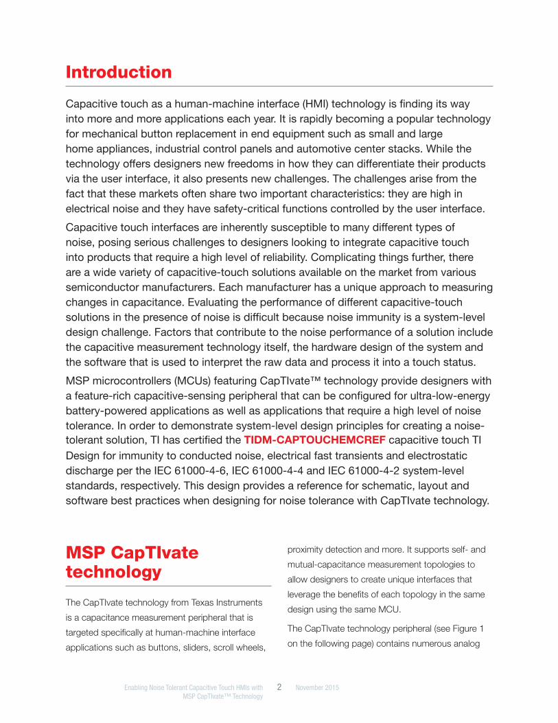
To enable designs with noise tolerance, the
capacitance-to-digital conversion is clocked by
a dedicated oscillator with frequency-hopping
capability and spread-spectrum modulation.
The ability to move the conversion around in
the frequency domain allows for the CapTIvate
technology software library to gather more
information about a product’s current operating
environment, preventing false touch detections in
the presence of electrical fast transients and ESD
events and allowing for accurate touch detection in
the presence of conducted noise.
Three-sided approach to immunity
Ultimately, creating a capacitive-touch interface that
is robust in the presence of many different possible
noise sources requires careful application of a
three-sided approach that consists of CapTIvate
technology features, hardware design techniques
and signal-processing algorithms. All three
elements must work together to provide immunity.
Only applying signal-processing algorithms while
neglecting good hardware design techniques will
not lead to a successful design.
1. CapTIvate technology features
• Integrator-based charge transfer engine
• Parasitic capacitance offset subtraction
• Frequency-hopping oscillator
• Spread-spectrum clock modulation in self
mode
2. Hardware design techniques
• Ground shielding of electrodes in layout
• 68pF filter capacitors on receive sensing lines
in mutual mode
3. Signal-processing algorithms
• Multi-frequency processing (MFP) algorithm
• IIR filtering + de-bounce
• Dynamic threshold adjustment (DTA)
algorithm in self mode
TIDM-CAPTOUCHEMCREF TI Design
The TIDM-CAPTOUCHEMCREF is a TI Design that
serves as a reference for how to properly design a
capacitive-touch user interface for noise immunity
using the self-capacitance and mutual-capacitance
topologies. This design was used for the system
Figure 3: Frequency hopping to avoid noisy bands
Enabling Noise Tolerant Capacitive Touch HMIs with 5 November 2015MSP CapTIvate™ Technology
level IEC 61000-4 certification of the CapTIvate
technology.
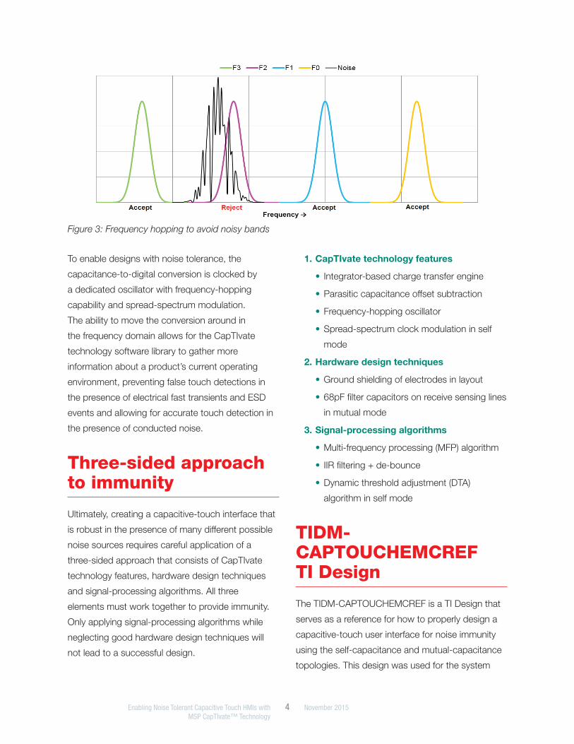
The TIDM-CAPTOUCHEMCREF consists of a
polycarbonate enclosure that is 9.5 inches long,
6.3 inches wide and 2.5 inches tall. The enclosure
itself serves as the overlay material for the
capacitive-touch interface. It is 2.54 mm (0.1 in) in
thickness. Internally there are two printed circuit
boards (PCBs): a power-supply module (PSM) and
a capacitive-sensing module (CSM) (see Figure
4). These two PCBs are connected to each other
internally via a 4-node wire harness. The complete
assembly is considered to be a single functional unit
during electromagnetic compatibility (EMC) testing.
The design is modular to allow for different PSM and
CSM combinations.
The self-capacitance-sensing module (CSM-SELF)
has 12 touch buttons and a 6-inch touch slider
composed of four electrodes, requiring a total of
16 touch-sensing pins. The mutual-capacitance-
sensing module (CSM-MUTUAL) has 32 touch
buttons in two 4×4 matrices (4 Rx lines and 4 Tx
lines per 16 buttons, requiring a total of 16 touch-
sensing pins). Both modules have backfiring LED
indicators to visually indicate the status of each
sensor and the system as a whole. Both modules
utilize the MSP430FR2633 CapTIvate MCU for
capacitive-touch sensing, as well as two TCA9535
I2C IO expander ICs for driving the status LEDs.
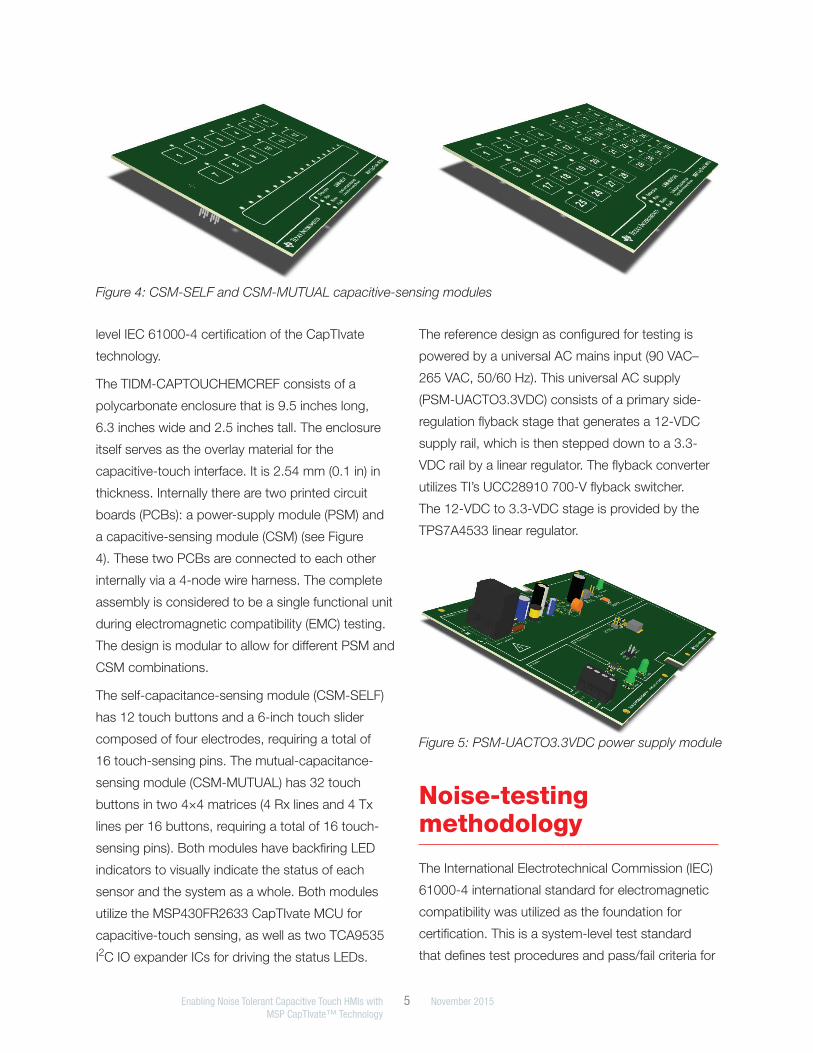
The reference design as configured for testing is
powered by a universal AC mains input (90 VAC–
265 VAC, 50/60 Hz). This universal AC supply
(PSM-UACTO3.3VDC) consists of a primary side-
regulation flyback stage that generates a 12-VDC
supply rail, which is then stepped down to a 3.3-
VDC rail by a linear regulator. The flyback converter
utilizes TI’s UCC28910 700-V flyback switcher.
The 12-VDC to 3.3-VDC stage is provided by the
TPS7A4533 linear regulator.
Figure 4: CSM-SELF and CSM-MUTUAL capacitive-sensing modules
Figure 5: PSM-UACTO3.3VDC power supply module
Noise-testing methodology
The International Electrotechnical Commission (IEC)
61000-4 international standard for electromagnetic
compatibility was utilized as the foundation for
certification. This is a system-level test standard
that defines test procedures and pass/fail criteria for
Enabling Noise Tolerant Capacitive Touch HMIs with 6 November 2015MSP CapTIvate™ Technology
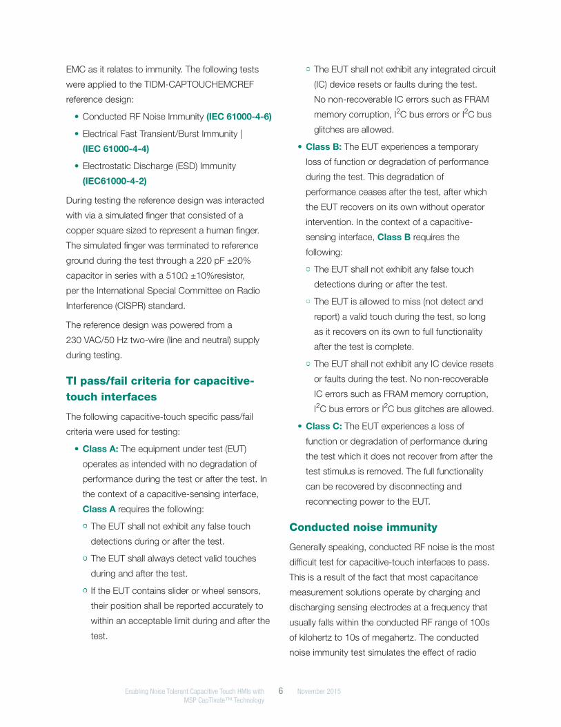
EMC as it relates to immunity. The following tests
were applied to the TIDM-CAPTOUCHEMCREF
reference design:
• Conducted RF Noise Immunity (IEC 61000-4-6)
• Electrical Fast Transient/Burst Immunity |
(IEC 61000-4-4)
• Electrostatic Discharge (ESD) Immunity
(IEC61000-4-2)
During testing the reference design was interacted
with via a simulated finger that consisted of a
copper square sized to represent a human finger.
The simulated finger was terminated to reference
ground during the test through a 220 pF ±20%
capacitor in series with a 510Ω ±10%resistor,
per the International Special Committee on Radio
Interference (CISPR) standard.
The reference design was powered from a
230 VAC/50 Hz two-wire (line and neutral) supply
during testing.
TI pass/fail criteria for capacitive-touch interfaces
The following capacitive-touch specific pass/fail
criteria were used for testing:
• Class A: The equipment under test (EUT)
operates as intended with no degradation of
performance during the test or after the test. In
the context of a capacitive-sensing interface,
Class A requires the following:
• The EUT shall not exhibit any false touch
detections during or after the test.
• The EUT shall always detect valid touches
during and after the test.
• If the EUT contains slider or wheel sensors,
their position shall be reported accurately to
within an acceptable limit during and after the
test.
• The EUT shall not exhibit any integrated circuit
(IC) device resets or faults during the test.
No non-recoverable IC errors such as FRAM
memory corruption, I2C bus errors or I2C bus
glitches are allowed.
• Class B: The EUT experiences a temporary
loss of function or degradation of performance
during the test. This degradation of
performance ceases after the test, after which
the EUT recovers on its own without operator
intervention. In the context of a capacitive-
sensing interface, Class B requires the
following:
• The EUT shall not exhibit any false touch
detections during or after the test.
• The EUT is allowed to miss (not detect and
report) a valid touch during the test, so long
as it recovers on its own to full functionality
after the test is complete.
• The EUT shall not exhibit any IC device resets
or faults during the test. No non-recoverable
IC errors such as FRAM memory corruption,
I2C bus errors or I2C bus glitches are allowed.
• Class C: The EUT experiences a loss of
function or degradation of performance during
the test which it does not recover from after the
test stimulus is removed. The full functionality
can be recovered by disconnecting and
reconnecting power to the EUT.
Conducted noise immunity
Generally speaking, conducted RF noise is the most
difficult test for capacitive-touch interfaces to pass.
This is a result of the fact that most capacitance
measurement solutions operate by charging and
discharging sensing electrodes at a frequency that
usually falls within the conducted RF range of 100s
of kilohertz to 10s of megahertz. The conducted
noise immunity test simulates the effect of radio

Enabling Noise Tolerant Capacitive Touch HMIs with 7 November 2015 MSP CapTIvate™ Technology
frequency noise coupling into power cables
leading to a product. The cables are used as the
coupling medium because the wavelengths of the
frequencies being tested are very large. A radiated
immunity test would not be feasible because the
antennae involved would be prohibitively large. As
an example, the TIDM-CAPTOUCHEMCREF drives
electrodes in the range of 1.4 MHz to 2 MHz. At
1.4 MHz, a half-wavelength is still over 100 meters.
Conducted noise creates problems for capacitive
touch because it leads to injected currents during
sampling, corrupting conversion results.
The conducted noise immunity test is also valuable
for systems that may be powered from a variety
of switching-power supplies. Low-cost switching
power supplies tend to be great sources of
common-mode emissions around their switching
frequency. This common-mode interference is very
similar to the stress applied during a conducted
noise test.
Class A immunity to conducted RF noise was tested
for by applying the IEC 61000-4-6 standard in three
different ways:
1. The standard noise frequency sweep (150 kHz
to 80 MHz, amplitude modulated on a 1 kHz
carrier at 80% depth) was applied with no
simulated finger present, to ensure that no false
detections occur during the duration of the
test.
2. The standard noise frequency sweep (150 kHz
to 80 MHz, amplitude modulated on a 1-kHz
carrier at 80% depth) was applied with a
simulated finger affixed to a touch button to
ensure that the button remains correctly in
touch detect throughout the duration of the
test.
3. Eight specific noise frequencies were dwelled
at. At each frequency, every touch sensor
on the reference design was verified to be
functioning correctly with no variations in
sensitivity. The specific stress frequencies
were chosen based on the worst-case noise
situations for capacitive sensing. The worst-
case noise frequencies are a function of
the conversion clock frequency used in the
capacitance-to-digital conversion. For both the
CSM-SELF and CSM-MUTUAL panel, the eight
stress frequencies are 1.4 MHz, 1.6375 MHz,
1.8375 MHz, 2.0 MHz, 9.87 MHz, 14.77 MHz,
18.055 MHz and 28.05 MHz.
Electrical fast transient / Burst immunity
It is very likely that a line-powered product with a
capacitive-touch interface will see electrical fast
transients at some point in its life. These transients,
typically in the 100s of volts to a few kilovolts, are
usually created by the switching of high-current
inductive loads. This type of stress is seen more
frequently in harsh industrial environments, but it is
also present in residential environments.
Fast transients tend to create a disturbance similar
to that of conducted noise, but the effect is more
broadband in frequency. In addition, transients are
short events that do not last for extended periods
of time. For this reason, the best defense against
fast transients is a well-designed power supply to
protect the sensitive ICs in the product, and the
application of de-bounce logic to prevent false
detections from a sample that was effected by a
transient.
Class B immunity to electrical fast transients was
tested for by applying the IEC 61000-4-4 standard.
Transients were coupled onto the AC mains supply
feeding the reference design. Line (L), neutral (N)
and line + neutral (L+N) coupling modes were
tested. Burst rates of 5 kHz and 100 kHz were
applied.
Enabling Noise Tolerant Capacitive Touch HMIs with 8 November 2015 MSP CapTIvate™ Technology
Electrostatic discharge immunity
When it comes to ESD, first line of defense for any
capacitive-touch interface is the overlay material and
mechanical design. Plastic overlays such as acrylic,
polycarbonate and ABS have high breakdown
voltages that often provide all of the necessary
protection. Care should be taken in enclosure
design to ensure that off-board connectors are
protected and that there are no unshielded gaps
where a discharge might spread into a product.
Designs that have exposed electrodes or extremely
thin overlays should utilize low-capacitance transient
voltage suppression (TVS) diodes to provide a low-
impedance path for discharge current, which can
be on the order of several amps in a system-level
ESD test.
IC protection aside, the strong electric fields that
result from electrostatic discharges can disrupt
capacitive touch measurements. The same de-
bounce methods that are applied for fast transient
protection work well for preventing false-touch
detections due to an electrostatic discharge near
the product, since discharges are momentary and
not continuous.
Class B immunity to ESD events was tested for by
applying the IEC 61000-4-2 standard. Because the
reference design utilizes an insulating polycarbonate
enclosure, contact discharge was applied to
horizontal and vertical coupling planes, and air
discharge was applied to the sensor area, power
connector and side of the enclosure.
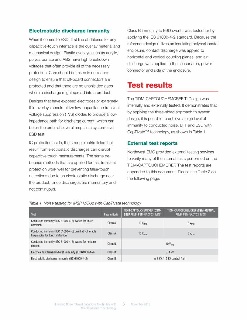
Test results
The TIDM-CAPTOUCHEMCREF TI Design was
internally and externally tested. It demonstrates that
by applying the three-sided approach to system
design, it is possible to achieve a high level of
immunity to conducted noise, EFT and ESD with
CapTIvate™ technology, as shown in Table 1.
External test reports
Northwest EMC provided external testing services
to verify many of the internal tests performed on the
TIDM-CAPTOUCHEMCREF. The test reports are
appended to this document. Please see Table 2 on
the following page.
Table 1. Noise testing for MSP MCUs with CapTIvate technology
Test Pass criteriaTIDM-CAPTOUCHEMCREF (CSM-SELF REVB, PSM-UACTO3.3VDC)
TIDM-CAPTOUCHEMCREF (CSM-MUTUAL REVB, PSM-UACTO3.3VDC)
Conducted immunity (IEC 61000-4-6) sweep for touch detection
Class A 10 Vrms 3 Vrms
Conducted immunity (IEC 61000-4-6) dwell at vulnerable frequencies for touch detection
Class A 10 Vrms 3 Vrms
Conducted immunity (IEC 61000-4-6) sweep for no false detects
Class B 10 Vrms
Electrical fast transient/burst immunity (IEC 61000-4-4) Class B ± 4 kV
Electrostatic discharge immunity (IEC 61000-4-2) Class B ± 8 kV / 15 kV contact / air

SLAY045A© 2015 Texas Instruments Incorporated
Important Notice: The products and services of Texas Instruments Incorporated and its subsidiaries described herein are sold subject to TI’s standard terms and conditions of sale. Customers are advised to obtain the most current and complete information about TI products and services before placing orders. TI assumes no liability for applications assistance, customer’s applications or product designs, software performance, or infringement of patents. The publication of information regarding any other company’s products or services does not constitute TI’s approval, warranty or endorsement thereof.
CapTIvate is a trademark of Texas Instruments. All other trademarks are the property of their respective owners.
Table 2. External testing performed by Northwest EMC
Equipment under test Test applied Stress level Pass criteria Test report
TIDM-CAPTOUCHEMCREF (CSM-SELF REVB, PSM-UACTO3.3VDC)
Conducted immunity (IEC 61000-4-6) sweep for touch detection
3 Vrms Class A TEXI0035, page 23
Conducted immunity (IEC 61000-4-6) dwell at vulnerable frequencies for touch detection
3 Vrms Class A TEXI0035, page 22
Conducted immunity (IEC 61000-4-6) sweep for no false detects
10 Vrms Class B TEXI0023, page 19
Electrical fast transient/Burst immunity (IEC 61000-4-4)
± 4 kV Class B TEXI0023, page 16
Electrostatic discharge immunity (IEC 61000-4-2) ± 4 kV / 8 kV contact / air Class B TEXI0023, page 11
TIDM-CAPTOUCHEMCREF (CSM-MUTUAL REVB, PSM-UACTO3.3VDC)
Conducted immunity (IEC 61000-4-6) sweep for touch detection
3 Vrms Class A TEXI0035, page 18
Conducted immunity (IEC 61000-4-6) dwell at vulnerable frequencies for touch detection
3 Vrms Class A TEXI0035, page 17
Conducted immunity (IEC 61000-4-6) sweep for no false detects
10 Vrms Class B TEXI0035, page 16
Electrical fast transient/Burst immunity (IEC 61000-4-4)
± 4 kV Class B TEXI0035, page 27
Electrostatic discharge immunity (IEC 61000-4-2) ± 8 kV / 15 kV contact / air Class B TEXI0035, page 11
IMPORTANT NOTICE FOR TI DESIGN INFORMATION AND RESOURCES
Texas Instruments Incorporated (‘TI”) technical, application or other design advice, services or information, including, but not limited to,reference designs and materials relating to evaluation modules, (collectively, “TI Resources”) are intended to assist designers who aredeveloping applications that incorporate TI products; by downloading, accessing or using any particular TI Resource in any way, you(individually or, if you are acting on behalf of a company, your company) agree to use it solely for this purpose and subject to the terms ofthis Notice.TI’s provision of TI Resources does not expand or otherwise alter TI’s applicable published warranties or warranty disclaimers for TIproducts, and no additional obligations or liabilities arise from TI providing such TI Resources. TI reserves the right to make corrections,enhancements, improvements and other changes to its TI Resources.You understand and agree that you remain responsible for using your independent analysis, evaluation and judgment in designing yourapplications and that you have full and exclusive responsibility to assure the safety of your applications and compliance of your applications(and of all TI products used in or for your applications) with all applicable regulations, laws and other applicable requirements. Yourepresent that, with respect to your applications, you have all the necessary expertise to create and implement safeguards that (1)anticipate dangerous consequences of failures, (2) monitor failures and their consequences, and (3) lessen the likelihood of failures thatmight cause harm and take appropriate actions. You agree that prior to using or distributing any applications that include TI products, youwill thoroughly test such applications and the functionality of such TI products as used in such applications. TI has not conducted anytesting other than that specifically described in the published documentation for a particular TI Resource.You are authorized to use, copy and modify any individual TI Resource only in connection with the development of applications that includethe TI product(s) identified in such TI Resource. NO OTHER LICENSE, EXPRESS OR IMPLIED, BY ESTOPPEL OR OTHERWISE TOANY OTHER TI INTELLECTUAL PROPERTY RIGHT, AND NO LICENSE TO ANY TECHNOLOGY OR INTELLECTUAL PROPERTYRIGHT OF TI OR ANY THIRD PARTY IS GRANTED HEREIN, including but not limited to any patent right, copyright, mask work right, orother intellectual property right relating to any combination, machine, or process in which TI products or services are used. Informationregarding or referencing third-party products or services does not constitute a license to use such products or services, or a warranty orendorsement thereof. Use of TI Resources may require a license from a third party under the patents or other intellectual property of thethird party, or a license from TI under the patents or other intellectual property of TI.TI RESOURCES ARE PROVIDED “AS IS” AND WITH ALL FAULTS. TI DISCLAIMS ALL OTHER WARRANTIES ORREPRESENTATIONS, EXPRESS OR IMPLIED, REGARDING TI RESOURCES OR USE THEREOF, INCLUDING BUT NOT LIMITED TOACCURACY OR COMPLETENESS, TITLE, ANY EPIDEMIC FAILURE WARRANTY AND ANY IMPLIED WARRANTIES OFMERCHANTABILITY, FITNESS FOR A PARTICULAR PURPOSE, AND NON-INFRINGEMENT OF ANY THIRD PARTY INTELLECTUALPROPERTY RIGHTS.TI SHALL NOT BE LIABLE FOR AND SHALL NOT DEFEND OR INDEMNIFY YOU AGAINST ANY CLAIM, INCLUDING BUT NOTLIMITED TO ANY INFRINGEMENT CLAIM THAT RELATES TO OR IS BASED ON ANY COMBINATION OF PRODUCTS EVEN IFDESCRIBED IN TI RESOURCES OR OTHERWISE. IN NO EVENT SHALL TI BE LIABLE FOR ANY ACTUAL, DIRECT, SPECIAL,COLLATERAL, INDIRECT, PUNITIVE, INCIDENTAL, CONSEQUENTIAL OR EXEMPLARY DAMAGES IN CONNECTION WITH ORARISING OUT OF TI RESOURCES OR USE THEREOF, AND REGARDLESS OF WHETHER TI HAS BEEN ADVISED OF THEPOSSIBILITY OF SUCH DAMAGES.You agree to fully indemnify TI and its representatives against any damages, costs, losses, and/or liabilities arising out of your non-compliance with the terms and provisions of this Notice.This Notice applies to TI Resources. Additional terms apply to the use and purchase of certain types of materials, TI products and services.These include; without limitation, TI’s standard terms for semiconductor products http://www.ti.com/sc/docs/stdterms.htm), evaluationmodules, and samples (http://www.ti.com/sc/docs/sampterms.htm).
Mailing Address: Texas Instruments, Post Office Box 655303, Dallas, Texas 75265Copyright © 2017, Texas Instruments Incorporated