empire builder set & dt100ir throttle user manual table of ... · empire builder set &...
TRANSCRIPT
Empire Builder Set & DT100IR Throttle User Manual Table of Contents
Page # 1.0 Introduction ............................................................................................ 4 2.0 Empire Builder Quick Installation Guide.......................................... 5
2.1 Connect the DB150 to the track & transformer ....................................... 5
2.2 Plug In Your DT100IR Throttle .............................................................. 5
2.3 Be sure track power is ON..................................................................... 6
2.4 Connect Your Layout To The Empire Builder......................................... 6
2.5 DT100IR Display Basics........................................................................ 7
2.6 Select & Run An Analog Loco on Address "00"...................................... 7
2.7 Decoder Address Basics ......................................................................... 8
2.8 How To Select & Run A DCC Equipped Loco Using 2 Digit Addressing. 9
2.7 Shutting Down the System...................................................................... 9
2.8 Resuming your session......................................................................... 10
2.9 Problems with Quick Start Procedure .................................................. 10
2.10 What's Next? .................................................................................. 11
Diagram #2: Expanded LocoNet Connection Example................................ 13 3.0 Transformers......................................................................................... 14 4.0 Track Wiring Considerations ............................................................... 14
4.1 Layout Power Districts........................................................................ 15
4.2 Using a DB150 as a Booster................................................................ 16
4.3 Setting up a Programming Track ........................................................ 17
4.4 Reverse Loop Wiring ........................................................................... 17
4.5 Using a DB150 as an AutoReversing Booster....................................... 18
4.6 Using PM4 for Power Management & AutoReversing.......................... 19
4.7 LocoNet Wiring Components ............................................................... 19 5.0 LocoNet: The Digitrax Difference!....................................................... 20 6.0 DB150 Control Panel: ............................................................................ 21
6.1 Power Input ........................................................................................ 21
6.2 Power On Indicator............................................................................. 22
6.3 Ground Terminal................................................................................. 22
6.4 RAIL A & RAIL B Terminals................................................................ 22

1
6.5 TRACK STATUS Indicator .................................................................. 22
6.6 OFF LINE Indicator............................................................................. 23
6.7 CONFIG A & B.................................................................................... 23
6.8 LocoNet Ports A & B............................................................................ 23
6.9 Mode Switch......................................................................................... 24
6.10 Scale Voltage Switch (O/G HO N) ...................................................... 24
6.11 DB150 Audible Sounds & Their Meanings .......................................... 24 DB150 AUDIBLE SOUNDS.................................................................. 24
Diagram 3: DT100IR Throttle Diagram...................................................... 25 7.0 DT100IR LocoNet Throttle Control Panel ........................................... 25 7.0 DT100IR LocoNet Throttle Control Panel ........................................... 26
7.1 General Color Codes........................................................................... 26
7.2 The Left & Right Throttle Knobs.......................................................... 26
7.3 Direction Indicators ...................................................................... 26
7.4 Program Mode Indicator ......................................................... 26
7.5 Address Mode Indicator............................................................ 26
7.6 LCD Display ....................................................................................... 26
7.7 RUN/STOP................................................................................... 27
7.8 SELECT/SET................................................................................ 27
7.9 MODE/DISP ................................................................................ 28
7.10 FUNC/F0................................................................................... 28
7.11 Function 1-8 Keys ............................................................................. 28
7.12 & Left & Right Throttle Direction Change Arrows.................. 28
7.13 Up/Add & Down/Delete Arrows......................................................... 28
7.14 Infrared Emitters................................................................................ 29 8.0 DT100IR: Major System Modes .......................................................... 29
8.1 Track Power On Mode ........................................................................ 29
8.2 Track Power Off Mode ........................................................................ 29
8.3 Stop Mode ........................................................................................... 29
8.4 Programming Mode ............................................................................ 29 9.0 LOCO Mode: Running Trains.............................................................. 29
9.1 The SE:L- Message.............................................................................. 30
2
9.2 Two Digit Short Address & % Speed Display ....................................... 30 Table I: Translation Table for 2 Digit Addresses .................................... 31
9.3 Locomotive Speed Control................................................................... 31
9.4 Locomotive Direction Control ........................................................ 31
9.5 Selecting Locomotives To Run ............................................................. 32
9.5.1 Selecting A 2 Digit Address............................................................... 32
9.5.2 Selecting A 4 Digit Address Loco ...................................................... 33
9.5.2 De-selecting a Loco You Are Not Running ......................................... 34 10.0 Walk around Operation On LocoNet ................................................. 35
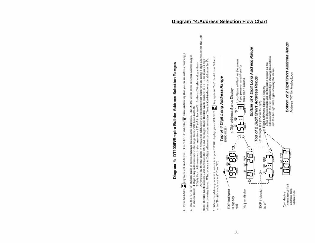
10.1 Forcing A Selection, or "Stealing" A "Lost" Locomotive..................... 35 Diagram #4:Address Selection Flow Chart ................................................. 36
10.2 DT100IR Slot Following-"Training Mode"......................................... 37
10.3 DB150 Loco Purging Strategy or Time Out! ...................................... 37 11.0 Controlling Lights & Functions .................................................. 38
11.1 Controlling Functions On Consisted Locomotives .............................. 39 12.0 Dispatching Locomotives .................................................................... 39 13.0 Decoder Status..................................................................................... 40
Table IIa: Loco STATUS Codes Right Digit ("y") ................................. 41
13.1 Status Editing a Decoder ................................................................... 41
13.2 Note for Lenz, Marklin, MRC & Arnold Decoders .............................. 42 14.0 Switch Mode............................................................................... 42 15.0 Multiple Unit Operations:................................................................... 43
15.1 MU-Link: Adding a Locomotive To A Consist ................................... 44
15.2 MU UNLINK: Breaking A Loco Out Of A Consist .............................. 45
15.2.1 Nested Consist Unlinking................................................................. 46
15.3 MU of Mismatched Locomotives ........................................................ 46 16.0 DT100IR Configuration Options ........................................................ 46 17.0 Infrared Tetherless Operation of DT100IR......................................... 48
17.1 LocoNet Connection ........................................................................... 49
17.2 Display power down........................................................................... 49
17.3 LocoNet ID change............................................................................. 50
17.4 “Tetherless” Operation ...................................................................... 50
17.5 Battery “Fuel Gauge”........................................................................ 51
17.6 Infrared Override ............................................................................... 52
3
17.7 Keyboard Lock Out ............................................................................ 52 18.0 Programming and Configuration..................................................... 53
18.1 How to Program 2 Digit Addresses..................................................... 54
18.2 How to Program Four Digit Addresses .............................................. 54
18.3 CV29 Configuration Register Programming...................................... 55
18.4 How to Program Other Configuration Variables ............................. 56 Table III: Most Commonly Used CV's ................................................... 57
18.5 User Loadable Speed Tables.............................................................. 57 Table V: Example Loadable Speed Table............................................... 59 Table VI: Decimal to Hexadecimal Conversion Chart ............................ 61
18.6 Operations Mode Programming.......................................................... 62 Diagram #5: Fast Clock Editing Flow Chart............................................... 64 19.0 DT100IR Fast Clock............................................................................ 64 19.0 DT100IR Fast Clock............................................................................ 65 20.0 DB150 Option Switch Setup................................................................ 67
Table VII: DB150 Option Switch Table ................................................. 68 21.0 Troubleshooting .................................................................................. 69
21.1 Clean Track....................................................................................... 69
21.2 The Quarter Trick.............................................................................. 69
21.3 The LT1 tester ................................................................................ 69
21.4 Decoder Won’t Respond ..................................................................... 69
21.5 Emergency Stop................................................................................. 70
21.6 Mechanical Drive Train Problems ..................................................... 70
21.7 "Strange" Locomotive Lights ............................................................ 70 22.0 Glossary................................................................................................ 71 23.0 FCC Information................................................................................ 76 24.0 Warranty and Repair Information:.................................................... 77
4
1.0 Introduction Congratulations on your purchase of a Digitrax Empire Builder Digital Command Control Set! The design of the Digitrax Command Control system lets you operate your layout the way you want to. With LocoNet you simply connect system components to build the layout control system that you always wanted! The Digitrax system reduces and simplifies layout wiring for new layouts. If you already have a layout, you probably won't need to rewire to install Digitrax. Your Empire Builder Starter Set has several DCC components: • The DB150 is your system's DCC command station. It generates the DCC
packets that tell the decoders what to do. It also produces Rail Sync so that all LocoNet devices that you connect to the system will work together. Generally you only have one command station attached to your layout.
• The DB150 is also a DCC booster. DCC boosters are connected to the command station and a power supply. Boosters receive DCC signals from the command station, amplify them and put them on the track along with the power to run the locomotives. You can have several boosters on your layout to provide additional power to run more locos.
• The DT100IR is the DCC throttle that comes with the Empire Builder. DCC throttles are the handhelds you use to tell the command station what you want the decoders to do. You will probably have several throttles on your layout if you have more than one person running trains at a time.
• Your Empire Builder also includes one Digitrax premium mobile decoder. The mobile decoders are installed in the locomotives to control the operation of the motor, lights and other functions of the loco.
There are many different combinations of Digitrax components that you can use
to set up a layout control system that is just right for you. You can combine Digitrax products with compatible decoders, boosters and computer
software made by other manufacturers. Your success with and enjoyment of our products are very important to us. After all, this is a hobby and it is FUN!!! Please read this manual carefully before you install your system. We have included lots of hints and operating ideas based on our experience with the Digitrax system. If you have questions not covered by this manual please contact your dealer.
5
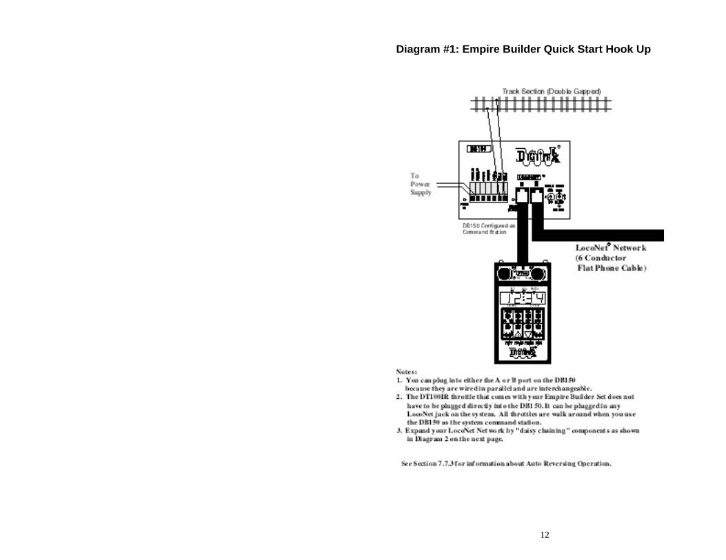
2.0 Empire Builder Quick Installation Guide These simple instructions will get you up and running quickly. You can investigate the specifics later but, for now let's get your trains running. A full description of all controls and technical reference information are included later in this manual. At this stage you will probably find the Empire Builder Instructional Video very helpful. See Diagram #1: Empire Builder Quick Start Hook Up.
2.1 Connect the DB150 to the track & transformer
1. Set the DB150's SCALE switch to the scale you are running. (N, HO, O\G\S). Always use the lowest possible setting that will power your layout.
2. Set the MODE switch on the DB150 to the RUN position. 3. Connect the two terminals marked POWER IN to the output of the
transformer. 4. Plug in the transformer to power up your booster. 5. The DB150 will beep once and the "POWER ON" led and the "TRACK
STATUS" led will come on.
2.2 Plug In Your DT100IR Throttle 1. For normal tethered operation, the DT100IR does not need a battery. If you
are not using a battery, the LCD screen will be off when you are unplugged from the system.
2. If you want to have the LCD active when you are unplugged from LocoNet,
simply insert a 9v battery in the battery compartment on the back side of the DT100IR case. When you insert the battery the DT100IR will beep and display "idLE".
3. Plug the DT100IR into either LocoNet jack on the DB150. 4. The DT100IR will beep & the LCD display will display "SE:L". If you
unplug the DT100IR from the DB150, the LCD will display "idLE" again if you are using a battery. If you are not using a battery, the LCD will go off when unplugged.
6
2.3 Be sure track power is ON 1. When track power is ON, the DT100IR's direction indicators show the
direction of the decoder assigned to the adjacent throttle knob: for digital locos, green means forward, red means reverse & OFF means that no address is selected. The DB150’s TRACK STATUS indicator is lit and the "OFF LINE" indicator will be off.
2. When track power is OFF, both the DT100IR's direction indicators are
steady orange, the DB150's TRACK STATUS indicator is off and DB150's OFF LINE indicator is on.
How To Turn Track Power On and Off
1. Turn track power on: Press and hold the key then press the key
while continuing to hold the RUN/STOP key. Release both keys when the system beeps and you see the lights on the throttle change from steady orange.
2. Turn track power off: Press and hold the key then press the
key while continuing to hold the RUN/STOP key. Release both keys when the system beeps and you see the lights on the throttle change from steady orange.
2.4 Connect Your Layout To The Empire Builder 1. The DB150 TRACK STATUS indicator should be on and POWER ON will
be lit. 2. Connect the DB150's RAIL A and RAIL B terminals to your track. 3. If your layout has any short circuits, the DB150 will beep 5 times and shut
down when it is connected to the DB150's RAIL A/B terminals. The POWER ON & TRACK STATUS leds will go off and the OFF LINE led will come on. The DB150 will resume operation once the short is cleared. If any problems with the track are detected at this stage, you should correct them before proceeding.
4. If you don't hear any beeps when you connect the DB150 to your layout,
use a screwdriver blade or a coin across the rails to cause a short circuit. You will hear the beeps and the DB150 will shut down as described in step 3. Remove the short and the DB150 will resume normal operation.
7
5. To be sure the DCC signal will be received everywhere on the layout, try the short circuit test at several locations. If the short you create does not shut down the DB150, review your wiring in that area of the layout to be sure you have enough track feeders to supply power to the track. Since the DCC signal travels with the power on the rails, it is important to have power to the track in all locations so that the decoders can see the signal and respond to your commands.
2.5 DT100IR Display Basics
1. The DT100IR has two throttles called the left throttle and the right throttle. 2. There are two direction indicators on the DT100IR for the left and right
throttles. If the direction indicator is lit, there is an address selected on that knob. The direction indicator that is blinking shows you which throttle's (left or right) information is currently displayed on the LCD screen.
3. The direction indicator also shows the direction of travel of a DCC
equipped loco selected on that throttle, red for reverse and green for forward.
4. If you are running an analog loco, the direction indicator will only indicate
change in track polarity and will not necessarily match the direction of travel of an analog loco.
5. For simple 2 digit address operation, the EXP led will not be lit. If the EXP
led is lit, that means that you are in the four digit address range and the LCD shows a four digit address alternately with a % speed for that address. Four digit addressing is discussed later.
2.6 Select & Run An Analog Loco on Address "00" 1. Activate the DT100IR's right throttle knob "R" by turning it a 1/4 turn in
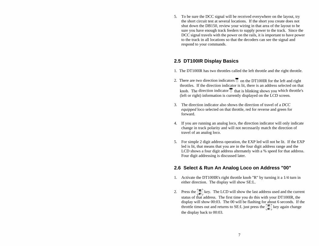
either direction. The display will show SE:L. 2. Press the key. The LCD will show the last address used and the current
status of that address. The first time you do this with your DT100IR, the display will show 00:03. The 00 will be flashing for about 6 seconds. If the throttle times out and returns to SE:L just press the key again change the display back to 00:03.
8
3. If 00 does not appear in your LCD, use either throttle knob to change the value to 00. With 00:03 showing on the LCD, press the key again to Set
address 00 on the right throttle. The direction indicator on the right side of the DT100IR will begin to flash and the LCD will display 00:00, meaning address 00 at 00% speed.
4. Turn the right throttle knob "R" clockwise slowly to 99% speed. The
DB150 "TRACK STATUS" indicator should change color as you change the speed setting.
5. Press the reverse direction key on the right side of the DT100IR. The
right direction indicator will toggle between blinking green and blinking red. The color will change each time you press the direction key.
6. Once you complete these observations successfully, turn the right throttle
counter clockwise to 0% speed. 7. Place an analog locomotive on the track. While the analog loco is sitting
still, you will hear the characteristic "singing" caused by the DCC track signal when applied to analog locomotives. Once the analog loco is moving, this sound will change and be less noticeable.
8. Use the right throttle knob to run the analog locomotive. As the value in the
% SPEED display increases, the locomotive on the track will begin to move. Press the reverse direction key on the right side of the DT100IR to reverse the direction of the locomotive. Turn the right throttle knob to 0% speed to stop the loco.
2.7 Decoder Address Basics 1. Each DCC decoder has an address. This can be a two digit address or a four
digit address. 2. To select a DCC locomotive and run it on either throttle, you must know its
address. 3. All Digitrax decoders are factory programmed to the "default" 2 digit
address "03." 4. If you do not know the address of the DCC locomotive you want to run, you
can simply re-program the decoder's address.
9
2.8 How To Select & Run A DCC Equipped Loco Using 2 Digit Addressing
1. Activate the DT100IR's left throttle knob "L" by turning it a 1/4 turn in
either direction. The display will show SE:L. 2. Press the (SELECT/SET) key. SE:L- will begin to flash. 3. Use either the throttle knob or the keys to select the locomotive
address you want to run on the LCD. For this example, dial up address "03". When "03" is flashing on the LCD above "ADDRESS".
4. Press (SELECT/SET) to "set" this address on left throttle. 5. The left throttle direction indicator will flash green indicating that the left
throttle information is currently displayed & that the DCC locomotive's direction is forward. The LCD will show 03:00, meaning that address 03 is running at 0% speed.
6. Use the left throttle knob to run the DCC locomotive with address 03. As
the value in the % SPEED display increases, the locomotive on the track will begin to move. Press the reverse direction key on the left side of the DT100IR to reverse the direction of the locomotive. Turn the left throttle knob to 0% speed to stop the loco.
7. Use the right throttle knob and reverse arrow key to control the analog loco
and the left throttle knob and reverse arrow key to control the DCC loco. You can control both at the same time.
8. Notice that as you use each throttle knob or direction key that the LCD
displays information for the last loco you sent a command to. Since the display can only show information for one throttle at a time, the throttle direction indicator shows which throttle is on display by flashing.
By now you are running two locomotives (one analog and one DCC) and you have learned some of the key concepts of using the DT100IR!! Please read the following sections for more in depth information about other features & capabilities of the Empire Builder set. ENJOY!
2.7 Shutting Down the System When you are finished with the quick installation session, shut down the Empire Builder as follows:
10
1. Switch the DB150's "MODE" switch to the "SLEEP" position . All
throttles attached to the system will go to "idLE" indicating that they are powered down and in "sleep" mode.
2. Turn off the power supply to the system. The power to the DB150 can be left on all the time. In "sleep" mode, the DB150 consumes very little energy. In this state the DB150 provides keep alive power to all throttles that are connected to LocoNet.
2.8 Resuming your session When you are ready to resume your session exactly where you left off: 1. Turn on the power supply to the system.
2. Switch the DB150 "MODE" switch to the "RUN" position . All
attached throttles will beep within a couple of seconds to indicate that LocoNet is active again and the "idLE" displays on the throttles will change.
3. Check the track status light on the DB150. If it is not lit then press the
& on any DT100 to restore track power to the system.
2.9 Problems with Quick Start Procedure If you had problems at any step in this Quick Installation section, try backing up a step until you get correct results. We carefully set up the installation procedure so that if you follow them carefully, any problems you encounter will be easy to isolate & debug. If you have any questions or problems, we encourage you to call, fax or e-mail your favorite Digitrax dealer. If your dealer is not able to help, please call Digitrax directly. There are thousands of successful Digitrax installations around the world and we want to be sure that yours is one of them. We have a lot of experience at helping a wide range of customers achieve successful installations. We have staff available to help during regular business hours, so if you are "spinning your wheels," don't suffer in silence!
11
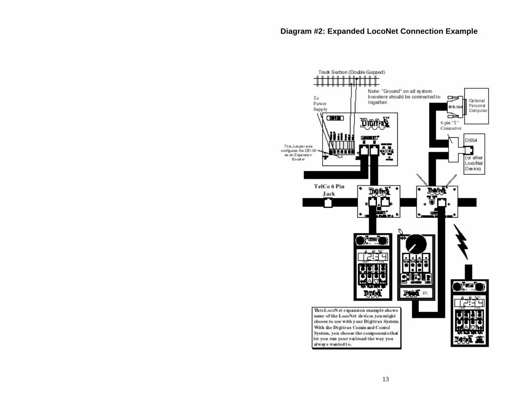
2.10 What's Next? Now that you have successfully set up the basic Empire Builder set, it's time to learn more about the features and options offered by the system. Read the manual and take time to understand and master each topic. See Diagram #2 for an example of how you might want to expand your Digitrax system in the future. Have fun running trains! QUICK INSTALLATION Notes for Users of Non-default Digitrax Decoders and Decoders Made by Other DCC Manufacturers: 1. The DB150 command station defaults to 128 speed step operation so, if you
are using a DCC locomotive with a decoder that does not have 128 step capability, please refer to section 14.0 for instructions to modify or Status Edit the speed step mode that the system will use for this locomotive address. OR see section 21.0 to change the global System default from 128 Steps to something else.
2. If you can't control the operation of the lights in your locomotive with the
DT100IR (in default 128, or 28 speed step mode), be sure that the decoder itself is programmed in advanced 28 speed step mode. Please refer to section 22.5 "Strange Lights" for corrective measures.
12
Diagram #1: Empire Builder Quick Start Hook Up
13
Diagram #2: Expanded LocoNet Connection Example
14
3.0 Transformers Digitrax recommends the PS515 power supply to power all DB150's. There are many other transformers and power packs that can supply the input power for the DB150. Check with your Digitrax dealer for suggestions. Most regular DC train power packs are not able to supply 5 amps to the DB150 booster, since they were designed to run 1 locomotive in a blocked system. With DCC you'll be running multiple locomotives on the same section of track so, you'll need to provide more power to each section. • The DB150 can accept either 50/60Hz AC or DC input. • Any power pack you use should be overload protected for a maximum
output of 5 amps. • Minimum input voltage is 12VAC or DC. • Maximum input voltage is 22 VAC or 28 VDC.
4.0 Track Wiring Considerations Early proponents of DCC touted the fact that you can hook up your railroad with just two wires. While this is technically correct, there are some issues that need clarification. You should run feeders from the power bus to each rail about every 10 feet. The general rule is: if your trains will run on your track with regular DC then they will run probably on DCC. Unless you need to section your layout for added power, the only gaps you need are for hard shorts like reverse loops & uninsulated frogs. If you are already wired for block control, you probably don't need to rewire. Just open all your blocks so that the entire track has power & you are ready to go. If you are using common rail wiring and need to section your layout, we recommend that you cut double gaps to separate the sections. Remember, no matter how you control your trains, you should always use safe wiring practices. Here are some track wiring considerations you'll need to consider. 1. Power connections to a large layout should be via a parallel conductor
power bus similar to that used in most conventional layouts, with feeder wires to the track about every 10 feet.
2. When using more than one booster, be sure that the Rail A and Rail B connections for all boosters are made in the same track orientation, i.e. Rail A to left rail and Rail B to right rail or vice versa.
3. Do not short either the Rail A or Rail B output of the DB150 to Ground.

15
4. To minimize the possibility of radio interference, twist all conductors. 5. Some experimentation may be needed on your layout to ensure no
circulating ground loops are present. This is especially true for existing layouts that have been added on to over the years.
6. Wire the power feeds away from the boosters and command stations, in a radial "star like" configuration to minimize the possibility of creating "magnetic induction" loops.
7. Do not place ANY filters or capacitors across the track. These will short out the DCC signals. Be sure that no capacitors are bridging your DCC sections.
Using DC and DCC together on the same layout 1. When running between Digitrax DCC track sections and adjacent
conventional DC powered tracks, both rails must have insulating gaps. 2. The DC supply must have some form of current control. A 5 to 10 Watt 12
Volt lamp placed in series with one of the DC power pack track leads will work for this purpose. This allows the DCC booster to drive the locomotive onto the DC track with minimum interruption and stress to the booster, decoders and locomotive wheels. When the lamp lights as the locomotive bridges the gaps it acts as a "shock absorber" between the DCC and DC track sections. It is best to cross these gaps quickly and not bridge the DCC and DCC sections for any longer than necessary.
4.1 Layout Power Districts Even though blocking is not required for train operation with DCC, dividing the layout up into power districts may be needed to:
1. Provide enough power to operate more locomotives than one power supply alone can handle. For example a 5 amp booster and power supply will operate between 6 and 10 average N-scale locomotives and between 4 and 6 HO locomotives.
16
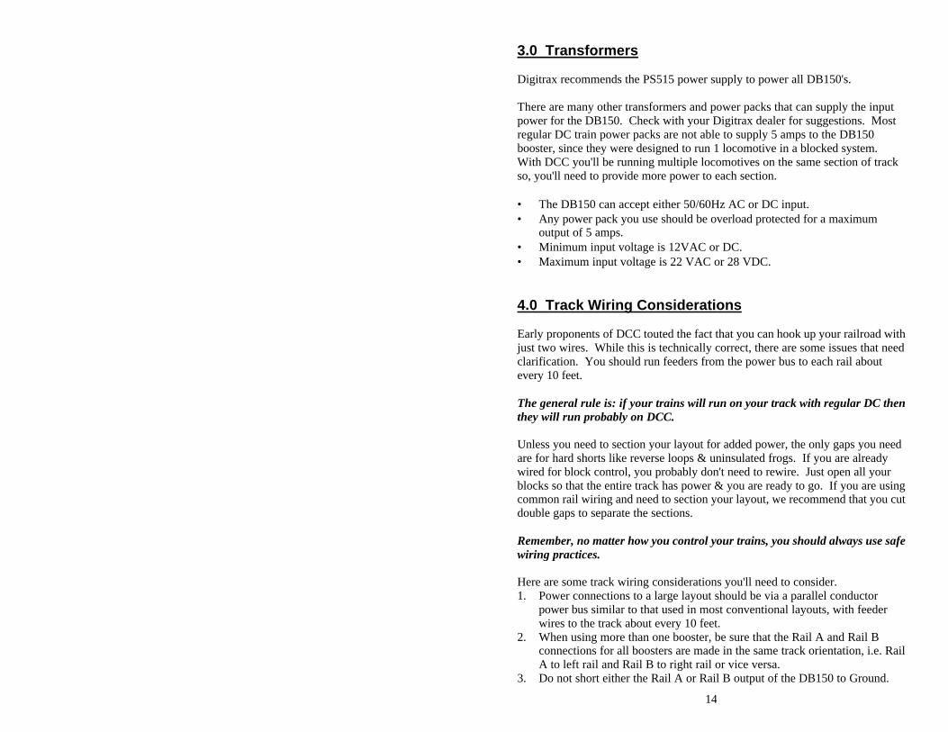
2. Prevent total layout shutdown when shorts occur in any given power district. If a short occurs in one district, only that district shuts down, the rest of the layout keeps operating. To section your layout into power districts: 1. Determine where you want to locate power districts. 2. Double gap the rails at each end of the power district 3. Connect a booster and power supply to each district. 4. Connect the boosters to the command station via LocoNet.
4.2 Using a DB150 as a Booster 1. Start with an un-powered DB150. 2. Connect the DB150's CONFIG A & GROUND terminals with a short
length of wire 3. Set theDB150's MODE switch to RUN. 4. Power up the DB150. The DB150 will automatically convert to
booster only operation when you power it up. 5. Connect to other DB150's on LocoNet via either LocoNet Port A or B
using regular 6 conductor RJ12 extension cables.
17
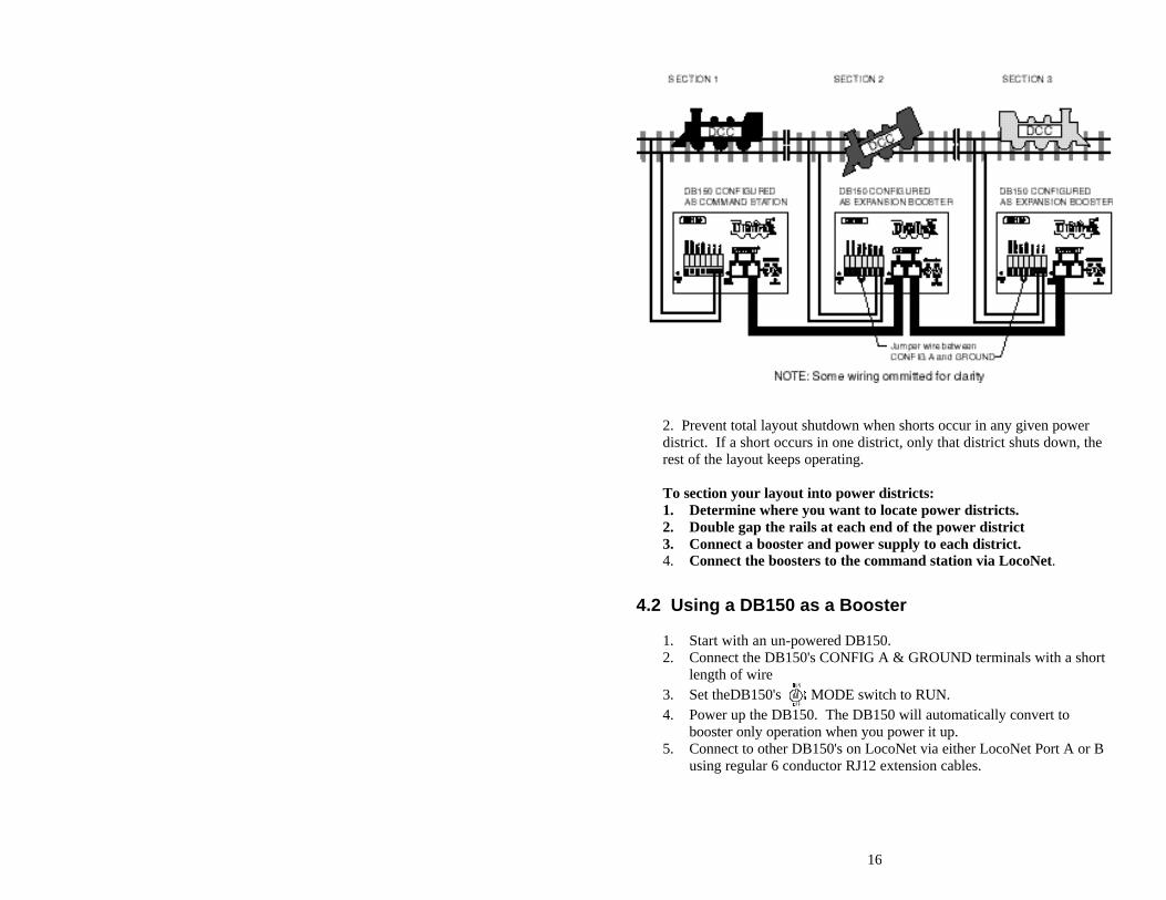
4.3 Setting up a Programming Track
Decoders are programmed when the command station sends programming information to them through the rails. The Empire Builder sends programming information as a broadcast message to any decoder on the track that is listening. To simplify programming, you will want to add an isolated programming track to your layout and program locomotives as follows:
1. Run the loco you want to program onto the programming track. 2. Throw the switch to disable the rest of the layout connected to the
DB150 command station. 3. Program the decoder. 4. Take the command station out of programming mode 5. Throw the switch controlling the programming track back to the normal
position. 6. Resume running your trains.
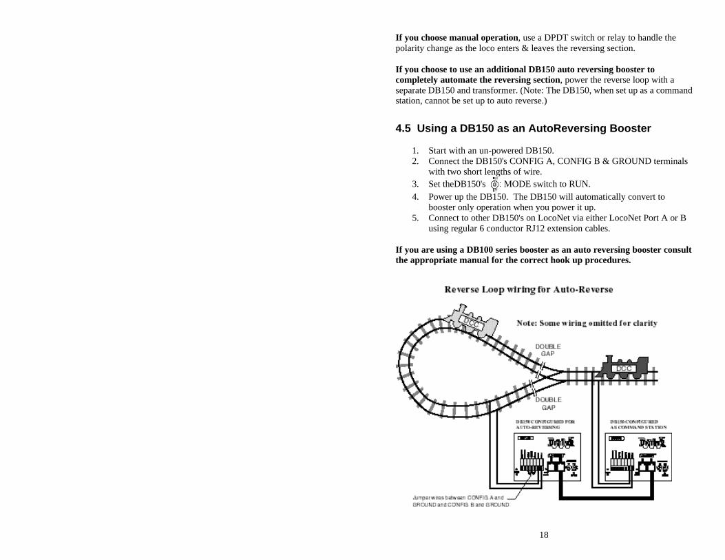
4.4 Reverse Loop Wiring You can operate reversing sections manually or automatically with Digitrax. You must double gap (completely isolate) both ends of the reversing section just like with any other layout.
18
If you choose manual operation, use a DPDT switch or relay to handle the polarity change as the loco enters & leaves the reversing section. If you choose to use an additional DB150 auto reversing booster to completely automate the reversing section, power the reverse loop with a separate DB150 and transformer. (Note: The DB150, when set up as a command station, cannot be set up to auto reverse.)
4.5 Using a DB150 as an AutoReversing Booster
1. Start with an un-powered DB150. 2. Connect the DB150's CONFIG A, CONFIG B & GROUND terminals
with two short lengths of wire. 3. Set theDB150's MODE switch to RUN. 4. Power up the DB150. The DB150 will automatically convert to
booster only operation when you power it up. 5. Connect to other DB150's on LocoNet via either LocoNet Port A or B
using regular 6 conductor RJ12 extension cables. If you are using a DB100 series booster as an auto reversing booster consult the appropriate manual for the correct hook up procedures.
19
Note that when the polarity change occurs, DCC equipped locomotives will continue at the speed & in the direction commanded but any analog engines running will reverse direction because they see the polarity change and respond to it. Two DB150's are needed to perform the auto reverse function. One DB150 acts as the master system phase reference and the other handles the polarity reversal for the reversing section. A single DB150 can be used to handle more than one reverse section at a time however, the unit can only fix one gap at a time. If more than one train is entering or leaving the reverse loops connected to a single booster at the same time, a short will occur. More than one train can be in the reverse loop at any time but, only one can cross the double gap at a time.
4.6 Using PM4 for Power Management & AutoReversing If you want the benefits of sectioning your layout but you don't need to add more power to run more trains, you can use a PM4 Quad Power Manager. With PM4 you can separate the output of a single booster into four sub-districts that can be set up as either auto-reversing or as smart circuit breakers. For more information about this option, contact your Digitrax dealer.
4.7 LocoNet Wiring Components The RJ12 is the 6 pin version of the RJ11 connector with all 6 pins loaded with conductors. This is the connector Digitrax uses for LocoNet. If you plan to make your own LocoNet cables, we strongly recommend that you purchase a good quality crimper. Also, use the LT-1 tester that came with your Empire Builder to test the cables to be certain they are good before installing them. Most Digitrax dealers can tell you where you can get these components locally. If you are willing to mail order, try DIGIKEY Phone # 1(800) DigiKey (1(800)344-4539). The Digitrax Universal Panel UP-3 provides a simple plug and play alternative to wiring RJ12 phone jacks around the layout. This fascia mounted panel provides 2 RJ12 jacks as well as "Track Status" and LocoNet Busy indicators. The back of the panel provides 2 RJ12 jacks for daisy chaining to the next LocoNet device on the network. For more information, contact your local dealer.
20
5.0 LocoNet: The Digitrax Difference! LocoNet is a powerful communications network specially designed for model railroad operation. It is engineered for rapid response even when many throttles & other devices are connected to the network. To engineer LocoNet, we used all of the best features of the powerful Ethernet CSMA/CD Local Area Network, the most universal worldwide hookup standard for computer networks. We ensured that LocoNet's protocol was Peer-to-Peer, which any LAN expert will confirm, gives the most powerful and expandable software architecture. LocoNet offers you a powerful yet simple "plug and play" connection scheme for wiring a high performance digital command control railroad layout. LocoNet is cost-effective and easy to maintain, & gives excellent high speed total system performance. In particular, the system is designed to be sure that as 100 or more throttles and hundreds of sensors and other devices are added to the system, there will be no operator perceptible delays as the LocoNet system executes all the operators' requests. Only a peer-to-peer technology on a true two-way multiple access network can meet these performance and expandability targets. LocoNet network gives you very simple, "free form" wiring and has passed the stringent radio interference rules of FCC Part 15 Class B, as required for home installations. This makes adding extra devices and features simple. No complex bus connection and termination rules to worry about. We have even run throttles and sensors on a LocoNet system over 2,000 feet long using low cost telephone wire! LocoNet is expandable so that as new features are added you will simply connect and "overlay" these capabilities to your existing working LocoNet system without disruption or any changes to existing hardware and software. Only a carefully crafted and smart Peer-to-Peer network can offer this open-ended expandability. So, LocoNet is more than just hardware, it is a number of operating systems, hardware, wiring, communications architecture and software innovations that are synthesized together to create the total LocoNet system concept. To the average user this means Sophistication without Complexity. You have a system that is easy to hook up, run and expand in the future. You don't need to worry about the high-tech details; Digitrax has already sweated them out for you. Just enjoy operating your layout- it's that simple and powerful!
21
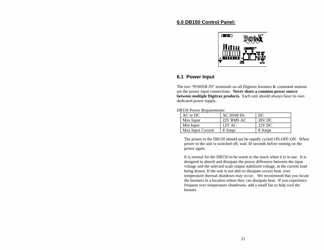
6.0 DB150 Control Panel:
6.1 Power Input The two “POWER IN” terminals on all Digitrax boosters & command stations are the power input connections. Never share a common power source between multiple Digitrax products. Each unit should always have its own dedicated power supply. DB150 Power Requirements:
AC or DC AC 50/60 Hz DC Max Input 22V RMS AC 28V DC Min Input 12V AC 12V DC Max Input Current 8 Amps 8 Amps
The power to the DB150 should not be rapidly cycled ON-OFF-ON. When power to the unit is switched off, wait 30 seconds before turning on the power again. It is normal for the DB150 to be warm to the touch when it is in use. It is designed to absorb and dissipate the power difference between the input voltage and the selected scale output stabilized voltage, at the current load being drawn. If the unit is not able to dissipate excess heat, over temperature thermal shutdown may occur. We recommend that you locate the boosters in a location where they can dissipate heat. If you experience frequent over temperature shutdowns, add a small fan to help cool the booster.
22
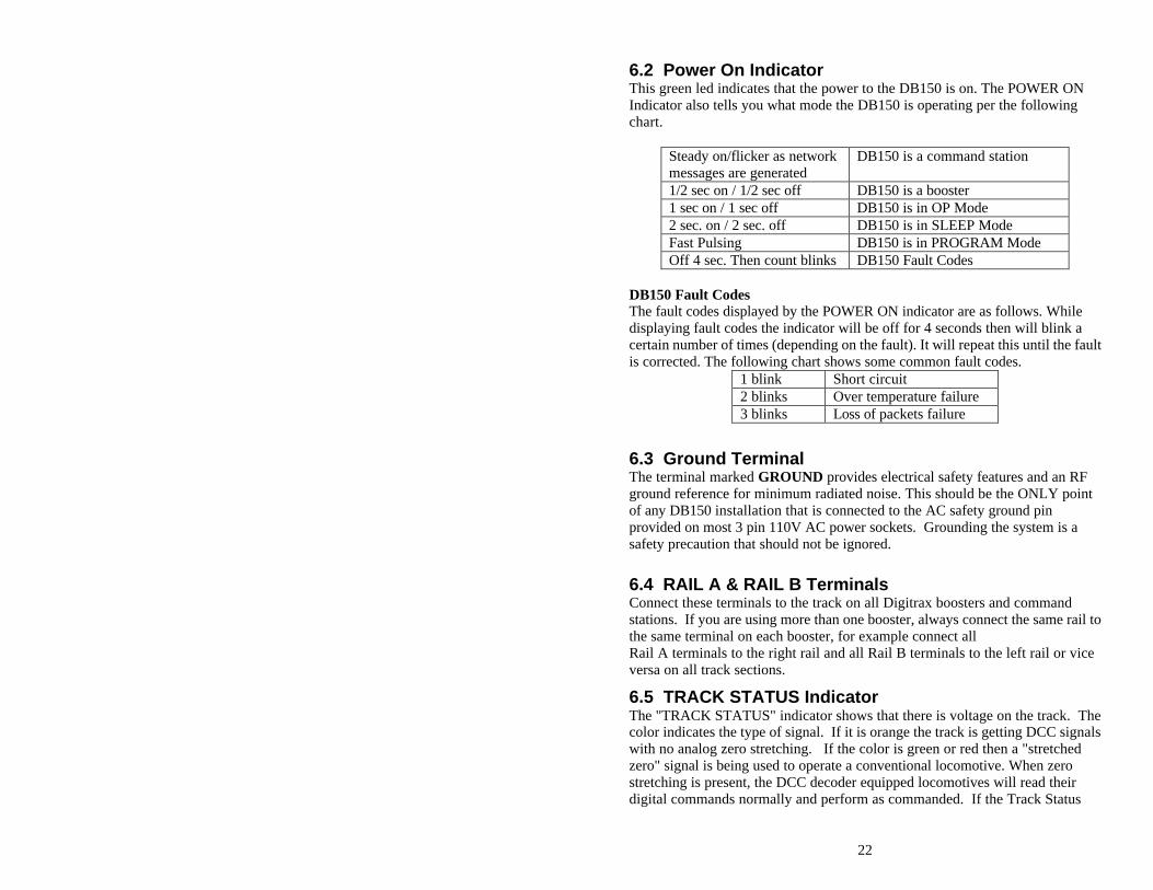
6.2 Power On Indicator This green led indicates that the power to the DB150 is on. The POWER ON Indicator also tells you what mode the DB150 is operating per the following chart.
Steady on/flicker as network messages are generated
DB150 is a command station
1/2 sec on / 1/2 sec off DB150 is a booster 1 sec on / 1 sec off DB150 is in OP Mode 2 sec. on / 2 sec. off DB150 is in SLEEP Mode Fast Pulsing DB150 is in PROGRAM Mode Off 4 sec. Then count blinks DB150 Fault Codes
DB150 Fault Codes The fault codes displayed by the POWER ON indicator are as follows. While displaying fault codes the indicator will be off for 4 seconds then will blink a certain number of times (depending on the fault). It will repeat this until the fault is corrected. The following chart shows some common fault codes.
1 blink Short circuit 2 blinks Over temperature failure 3 blinks Loss of packets failure
6.3 Ground Terminal The terminal marked GROUND provides electrical safety features and an RF ground reference for minimum radiated noise. This should be the ONLY point of any DB150 installation that is connected to the AC safety ground pin provided on most 3 pin 110V AC power sockets. Grounding the system is a safety precaution that should not be ignored.
6.4 RAIL A & RAIL B Terminals Connect these terminals to the track on all Digitrax boosters and command stations. If you are using more than one booster, always connect the same rail to the same terminal on each booster, for example connect all Rail A terminals to the right rail and all Rail B terminals to the left rail or vice versa on all track sections.
6.5 TRACK STATUS Indicator The "TRACK STATUS" indicator shows that there is voltage on the track. The color indicates the type of signal. If it is orange the track is getting DCC signals with no analog zero stretching. If the color is green or red then a "stretched zero" signal is being used to operate a conventional locomotive. When zero stretching is present, the DCC decoder equipped locomotives will read their digital commands normally and perform as commanded. If the Track Status
23
LED is not lit there is no voltage on the track, the track power to the DB150 may be OFF.
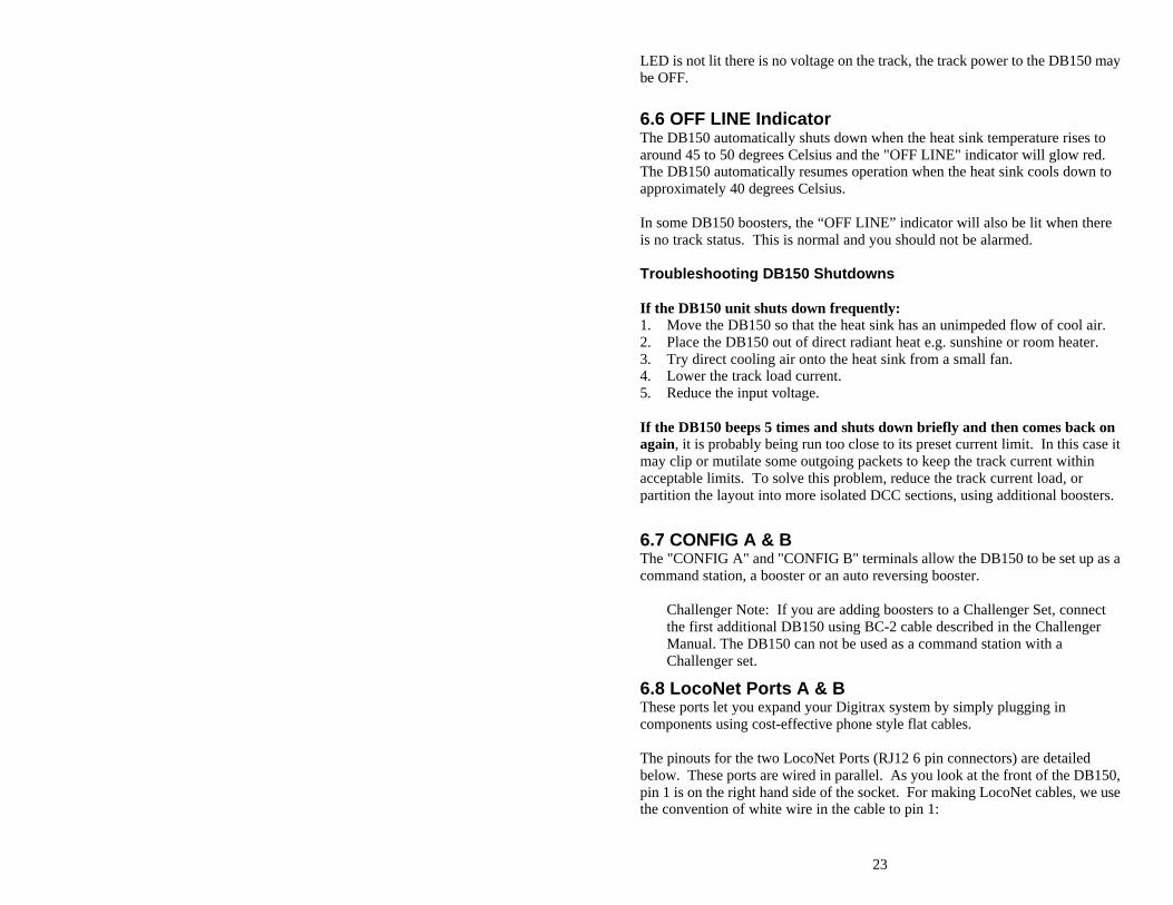
6.6 OFF LINE Indicator The DB150 automatically shuts down when the heat sink temperature rises to around 45 to 50 degrees Celsius and the "OFF LINE" indicator will glow red. The DB150 automatically resumes operation when the heat sink cools down to approximately 40 degrees Celsius. In some DB150 boosters, the “OFF LINE” indicator will also be lit when there is no track status. This is normal and you should not be alarmed. Troubleshooting DB150 Shutdowns If the DB150 unit shuts down frequently: 1. Move the DB150 so that the heat sink has an unimpeded flow of cool air. 2. Place the DB150 out of direct radiant heat e.g. sunshine or room heater. 3. Try direct cooling air onto the heat sink from a small fan. 4. Lower the track load current. 5. Reduce the input voltage. If the DB150 beeps 5 times and shuts down briefly and then comes back on again, it is probably being run too close to its preset current limit. In this case it may clip or mutilate some outgoing packets to keep the track current within acceptable limits. To solve this problem, reduce the track current load, or partition the layout into more isolated DCC sections, using additional boosters.
6.7 CONFIG A & B The "CONFIG A" and "CONFIG B" terminals allow the DB150 to be set up as a command station, a booster or an auto reversing booster.
Challenger Note: If you are adding boosters to a Challenger Set, connect the first additional DB150 using BC-2 cable described in the Challenger Manual. The DB150 can not be used as a command station with a Challenger set.
6.8 LocoNet Ports A & B These ports let you expand your Digitrax system by simply plugging in components using cost-effective phone style flat cables. The pinouts for the two LocoNet Ports (RJ12 6 pin connectors) are detailed below. These ports are wired in parallel. As you look at the front of the DB150, pin 1 is on the right hand side of the socket. For making LocoNet cables, we use the convention of white wire in the cable to pin 1:
24
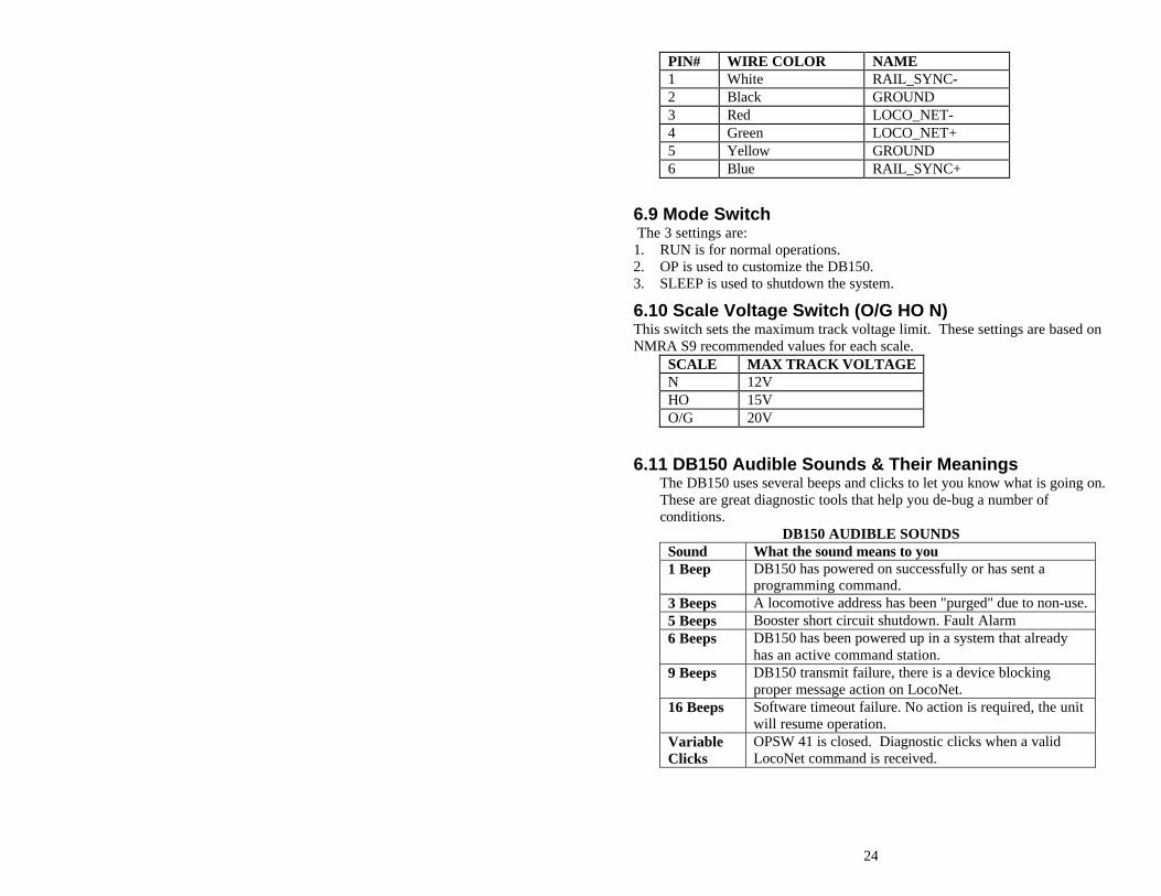
PIN# WIRE COLOR NAME 1 White RAIL_SYNC- 2 Black GROUND 3 Red LOCO_NET- 4 Green LOCO_NET+ 5 Yellow GROUND 6 Blue RAIL_SYNC+
6.9 Mode Switch The 3 settings are: 1. RUN is for normal operations. 2. OP is used to customize the DB150. 3. SLEEP is used to shutdown the system.
6.10 Scale Voltage Switch (O/G HO N) This switch sets the maximum track voltage limit. These settings are based on NMRA S9 recommended values for each scale.
SCALE MAX TRACK VOLTAGE N 12V HO 15V O/G 20V
6.11 DB150 Audible Sounds & Their Meanings The DB150 uses several beeps and clicks to let you know what is going on. These are great diagnostic tools that help you de-bug a number of conditions.
DB150 AUDIBLE SOUNDS Sound What the sound means to you 1 Beep DB150 has powered on successfully or has sent a
programming command. 3 Beeps A locomotive address has been "purged" due to non-use. 5 Beeps Booster short circuit shutdown. Fault Alarm 6 Beeps DB150 has been powered up in a system that already
has an active command station. 9 Beeps DB150 transmit failure, there is a device blocking
proper message action on LocoNet. 16 Beeps Software timeout failure. No action is required, the unit
will resume operation. Variable Clicks
OPSW 41 is closed. Diagnostic clicks when a valid LocoNet command is received.
25
Diagram 3: DT100IR Throttle Diagram

26
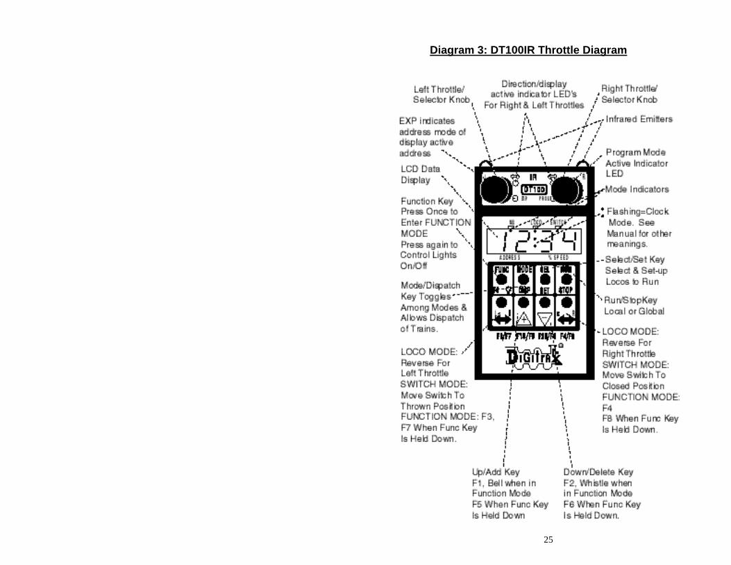
7.0 DT100IR LocoNet Throttle Control Panel
7.1 General Color Codes The DT100IR control panel is color coded according to how the keys are used. Green keys & indicators are for loco speed & direction control. Red key is "RUN/STOP." Blue keys are related to function control. When the function mode is active,
the green keys in the bottom row take on the "blue" meanings F3/F7, F1 /F5, F2 /F6, F4/F8.
7.2 The Left & Right Throttle Knobs The throttle knobs on the DT100IR are "encoders." They give very smooth, fine speed control. In 128 speed step mode it takes several complete turns of the knob to go from stop to full speed. When you select a locomotive that is moving & set it on a throttle knob, the throttle continues to run the locomotive at the same speed and direction regardless of the position of the knob. You can customize the tracking characteristics of these knobs for either "straight line" or "ballistic" tracking. With "straight line" tracking each movement of the knob causes a fixed rate of change. With "ballistic" tracking, the faster you move the throttle knob, the faster the data changes in the throttle. Your DT100IR was shipped with "ballistic tracking" as the default setting.
7.3 Direction Indicators These led's indicate the direction of DCC equipped locos selected on the L or R throttle. Red = Loco in Reverse Green = Loco in Forward Flashing = Throttle Active in LCD Display Both Flashing orange = System is in "Stop" with track power ON Both Solid orange = System Track power is OFF.
7.4 Program Mode Indicator Indicates that the DT100IR throttle is in programming mode. When this mode is active the throttle knobs & keys will not control any selected locomotives. In programming mode you will use the knobs and keys to change configuration variables (CVs) in your DCC locos.
7.5 Address Mode Indicator OFF The loco displayed on the DT100IR is using a 2 digit short address. Steady RED
The loco displayed on the DT100IR is using a 4 digit long address.
7.6 LCD Display The DT100IR's LCD screen is used to display several different types of information to the operator.
27
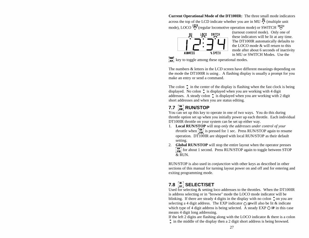
Current Operational Mode of the DT100IR: The three small mode indicators
across the top of the LCD indicate whether you are in MU (multiple unit
mode), LOCO (regular locomotive operation mode) or SWITCH (turnout control mode). Only one of these indicators will be lit at any time. The DT100IR automatically defaults to the LOCO mode & will return to this mode after about 6 seconds of inactivity in MU or SWITCH Modes. Use the
key to toggle among these operational modes. The numbers & letters in the LCD screen have different meanings depending on the mode the DT100IR is using . A flashing display is usually a prompt for you make an entry or send a command. The colon in the center of the display is flashing when the fast clock is being displayed. No colon is displayed when you are working with 4 digit addresses. A steady colon is displayed when you are working with 2 digit short addresses and when you are status editing.
7.7 RUN/STOP You can set up this key to operate in one of two ways. You do this during throttle option set up when you initially power up each throttle. Each individual DT100IR throttle on your system can be set up either way. 1. Local RUN/STOP will stop only the addresses under control of your
throttle when is pressed for 1 sec. Press RUN/STOP again to resume operation. DT100IR are shipped with local RUN/STOP as their default setting.
2. Global RUN/STOP will stop the entire layout when the operator presses
for about 1 second. Press RUN/STOP again to toggle between STOP & RUN.
RUN/STOP is also used in conjunction with other keys as described in other sections of this manual for turning layout power on and off and for entering and exiting programming mode.
7.8 SELECT/SET Used for selecting & setting loco addresses to the throttles. When the DT100IR is address selecting or in "browse" mode the LOCO mode indicator will be blinking. If there are steady 4 digits in the display with no colon on you are selecting a 4 digit address. The EXP indicator will also be lit & indicate which type of 4 digit address is being selected. A steady EXP in this case means 4 digit long addressing. If the left 2 digits are flashing along with the LOCO indicator & there is a colon
in the middle of the display then a 2 digit short address is being browsed.
28
This key is also used in other modes to select or complete an operation.
7.9 MODE/DISP Mode: Press to move from one operational mode to another. LOCO is the DT100IR's default mode since most of the time you are running locomotives.
Press to change to SWITCH then to MU then back to LOCO. Dispatch: To Dispatch or offer a locomotive you have set up on a DT100IR to a UT1, UT2 or a BT2 limited throttle, press this key while in Select Address mode.
7.10 FUNC/F0 Press once to enter Function Mode. The display shows "Fn:oo" with the oo flashing to indicate that you must choose which function you wish to toggle. Press again to toggle the directional lights on or off. OR, press the key above F1, F2, F3 or F4 to toggle any of those functions that are available in your loco. Function 2 is a special key because it is non latching, this allows you to activate a function while the key is held down & deactivate it when the key is released. This makes it easy to simulate blowing a horn. Press & hold the key while pressing the key above F5, F6, F7, F8 to toggle functions 5-8 on & off. In Edit & Programming modes is also used to cycle among several choices.
7.11 Function 1-8 Keys Active when in function mode. Use the keys above these designations to access the various decoder functions. F2 is non latching. See section 12.0 for more information about using these keys.
7.12 & Left & Right Throttle Direction Change Arrows Changes the direction of the loco on the related throttle. The key changes
direction of the address on the "R" or Right Throttle. The key changes direction of the address on the "L" or Left Throttle. Also used to select the position to which you want to set a switch or turnout: t=thrown c=closed
7.13 Up/Add & Down/Delete Arrows Use to browse addresses & increase/decrease speed. Use to MU-Link & MU-Unlink locomotives from consists. These keys are also used when you are using various system editors. These +/- keys can be configured to be repeating so that if you hold a key down it will repeat until you release the key. This is the normal default when the
29
"ballistic knob" mode is selected as the Option setup for this throttle, see section 17.0.
7.14 Infrared Emitters Sends an infrared signal to any compatible LocoNet Infrared receiver for tetherless operation.
8.0 DT100IR: Major System Modes The DT100IR's MAJOR mode changes are controlled when the DT100IR is connected to LocoNet by using the key in conjunction with other keys as described below.
8.1 Track Power On Mode When track power is off, press and hold the then press the key at the same time. Release both keys when the DB150 beeps and the track power light comes on.
8.2 Track Power Off Mode When track power is on, press and hold the then press the key at the same time. Release both keys when the DB150 beeps and the track power light goes off.
8.3 Stop Mode If the track power is on and trains are running the keys & will make the
system go to STOP, and all trains will stop. Pressing & while the layout is in STOP will change it back to RUN. When the system is in STOP Mode both of the direction indicators will blink orange. In this state there is power to the track but all locomotives are stopped.
8.4 Programming Mode Any DT100IR can program locomotive decoders. To enter programming mode, press and hold the then press the key at the same time. Release both keys when the LCD shows "PagE" and the Program Indicator light comes on. To exit programming mode, press and hold the then press the key at the same time. Release the keys when the LCD shows "SE:L-" and the Program Indicator light goes off.
9.0 LOCO Mode: Running Trains LOCO mode is the default mode for the DT100IR because it is the mode you use to run the trains. If you change to SWITCH or MU mode & don't do anything, the unit will return to LOCO mode in about 6 seconds. If a throttle has a locomotive selected & under its control, the associated direction indicator will be green if the locomotive's direction is forward & red
30
if its direction is reverse. In addition, if the direction indicator is flashing, that throttle's locomotive Address & Speed information is currently showing on the LCD screen. For example: if the on the right side of the DT100IR is flashing red, this means that the ADDRESS & % SPEED in the display are for the loco that is currently being run by the right throttle knob & that locomotive's direction is reverse. The red EXP indicator shows whether the locomotive address controlled by the throttle is using a 2 digit short address or a 4 digit long address. To display the information for the throttle not currently in the display, turn the other throttle knob just a little (or change the direction of the loco) and the display will pop up.
9.1 The SE:L- Message If a throttle knob does not have a locomotive selected when you try to make it display its information with its knob or direction change arrow, the display will show "SE:L-". This is a prompt for you to select a locomotive and set it to that throttle.
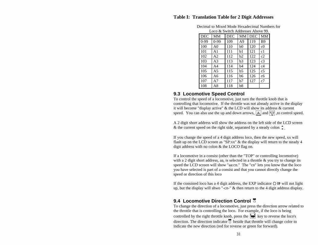
9.2 Two Digit Short Address & % Speed Display When you have a loco with a 2 digit short address the EXP indicator is off & the numbers to the left of the colon & above the word "ADDRESS," are the address of the locomotive & the numbers to the right of the : & above the words "% SPEED" are the % speed for the throttle currently displayed. The speed is shown as a % of full speed & is NOT actual speed step codes sent to the decoders in the locomotives. Note: For addresses above 99 please refer to Table I below to translate the mixed mode hexadecimal value that shows in the display for addresses above 99.
31
Table I: Translation Table for 2 Digit Addresses
Decimal to Mixed Mode Hexadecimal Numbers for Loco & Switch Addresses Above 99.
DEC MM DEC MM DEC MM 0-99 0-99 109 A9 119 B9 100 A0 110 b0 120 c0 101 A1 111 b1 121 c1 102 A2 112 b2 122 c2 103 A3 113 b3 123 c3 104 A4 114 b4 124 c4 105 A5 115 b5 125 c5 106 A6 116 b6 126 c6 107 A7 117 b7 127 c7 108 A8 118 b8
9.3 Locomotive Speed Control To control the speed of a locomotive, just turn the throttle knob that is controlling that locomotive. If the throttle was not already active in the display it will become "display active" & the LCD will show its address & current speed. You can also use the up and down arrows, and ,to control speed. A 2 digit short address will show the address on the left side of the LCD screen & the current speed on the right side, separated by a steady colon . If you change the speed of a 4 digit address loco, then the new speed, xx will flash up on the LCD screen as "SP:xx" & the display will return to the steady 4 digit address with no colon & the LOCO flag on. If a locomotive in a consist (other than the "TOP" or controlling locomotive) with a 2 digit short address, aa, is selected in a throttle & you try to change its speed the LCD screen will show "aa:cn." The "cn" lets you know that the loco you have selected is part of a consist and that you cannot directly change the speed or direction of this loco If the consisted loco has a 4 digit address, the EXP indicator will not light up, but the display will shwo "-cn-" & then return to the 4 digit address display.
9.4 Locomotive Direction Control To change the direction of a locomotive, just press the direction arrow related to the throttle that is controlling the loco. For example, if the loco is being controlled by the right throttle knob, press the key to reverse the loco's direction. The direction indicator beside that throttle will change color to indicate the new direction (red for reverse or green for forward).
32
If you change direction while a loco is moving it will slow down to 0 speed and then speed up to the commanded speed according to the decoder's programmed deceleration and acceleration characteristics. Since it is more prototypical to stop the loco before changing directions you will probably want to move the throttle to 0 speed & stop the loco before commanding a direction change. You can program a decoder with acceleration and deceleration rates that simulate the scale effects of braking the train. Then when you command an instant reverse of direction, the system will simulate braking by causing the locomotive to slow down at the programmed deceleration rate, come to a stop & accelerate again at the programmed acceleration rate.
9.5 Selecting Locomotives To Run With the DB150 there are three options for addressing and programming
locomotives. You can use these three addressing modes at any time in any combination you choose.
Address "00" Analog Address: For locomotives without decoders 2 Digit Short Addressing: Also called short addressing can be used with any
DCC decoder 4 Digit Long Addressing: Also called Extended Packet Format, or long
addressing can be used with any DCC EPF decoder that supports this feature. The DB150 address range looks like this: Address in DT100IR Display
EXP indicator
What these addresses represent
00 off The Analog Loco 01: to c7: (127) off 2 Digit Short Address Range 0128 to 9980 RED steady 4 Digit Long Address Range
This addressing scheme provides backward compatibility with all existing DCC decoders & does not force you to replace any decoders while allowing four digit addressing for any decoder on the layout. Note: If the right hand side of the status display shows "FF" during address selection, this means that the command station has reached the limit of locomotives that it can refresh at one time. Releasing some locomotives back to the system will allow you to continue the selection process.
9.5.1 Selecting A 2 Digit Address 1. Turn the throttle knob you want to use to control the loco about 1/8 turn
to make it the "display active" throttle.
33
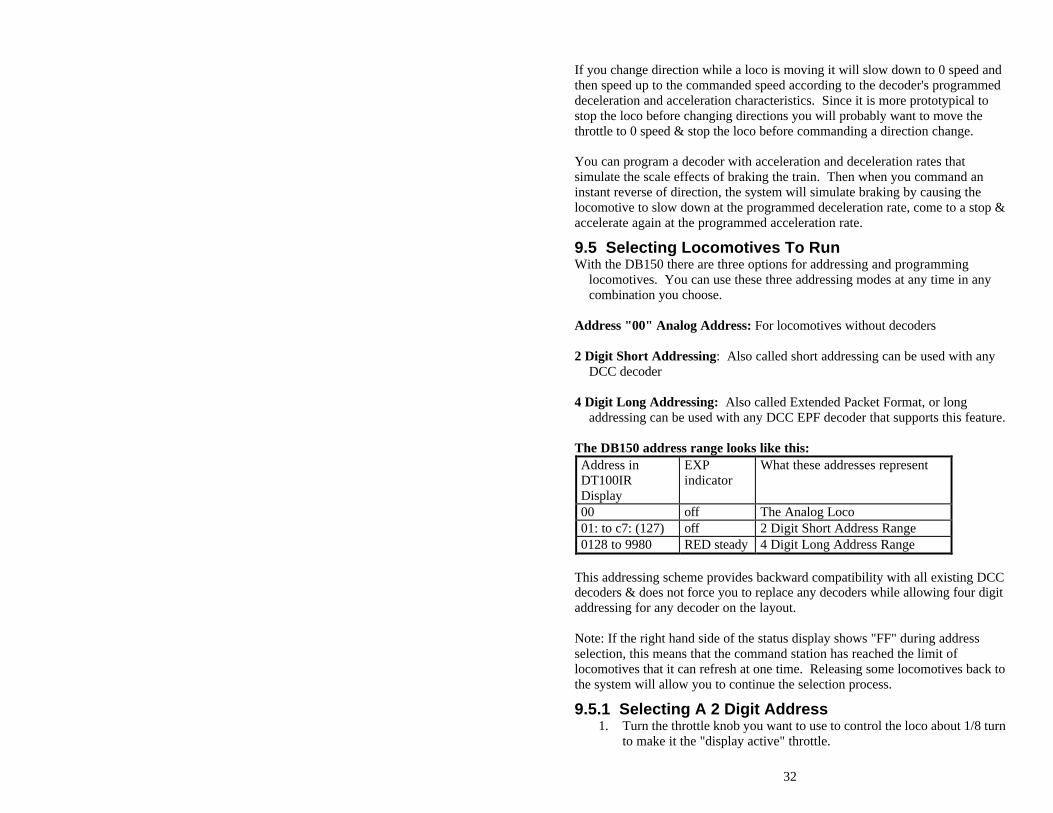
2. Press the key to enter "address selection" mode. The left hand side of the LCD screen will flash two digits to prompt you to choose a 2 digit. The right-hand side of the display shows various status codes as you "browse" through the 2 digit addresses. The meanings of these codes are detailed later in the status editing section.
This display shows locomotive address 21 selected but not set, since the address 2 digits are flashing.
3. Turn either throttle knob or use the & keys to browse through the addresses until the one you want to run appears in the LCD.
4. Press the key again to SET that 2 digit address to the throttle you selected in step 1. The LCD screen will show the locomotive's address and speed information for the loco you just selected.
If you try to access a loco address that is active on another throttle: 1. When you press SEL/SET to set the address to the throttle, the DT100IR
will display "xx:3x" when you press to set the address. The "3" in the right side of the display means that the loco is active on another throttle in the system.
2. The DT100IR's display will change back to SE:L- & the throttle direction indicator will not light up.
3. The address "SET" request failed because the system won't let you select a locomotive address that is active or "in-use" on another throttle anywhere else on the system. This is true even if the loco address is being used by a completely different throttle or even a remote computer hooked up to the system!
4. If your address selection failed, you can press again & scan for a different loco address that is not "in use" or you can have the operator who is using the loco de-select it from their throttle so that you can select it to run on your throttle.
In certain cases you can override this security interlock & "steal" an "in-use" locomotive. See section 10.1 for details, & use this facility wisely.
9.5.2 Selecting A 4 Digit Address Loco Long Address Selection: 1. Press down & HOLD the key 2. While holding the SEL/SET key, turn one of the throttle knobs
34
3. DT100IR will immediately enter the 4 digit long address range. The red EXP indicator will glow steady to let you know that you are in the 4 digit long address range.
4. Release the key & browse for the 4 digit long address you want to run using the left throttle knob for the first two digits and the right throttle knob for the second two digits.
5. When the 4 digit long address you want to use is in the display, press the key to set it to the throttle.
To return to 2 digit address modd, turn the left knob counter clockwise until the red "EXP" led goes off. When you are selecting a locomotive and you dial above 2 digit address "c7" (127) the DT100IR changes automatically to 4 digit address mode & the EXP indicator changes to steady red. Once you enter the four digit address mode, the left throttle knob will increment the two left hand address digits shown in the LCD by 100's (from 100 up to 9900) and the right throttle knob will increment the right hand two address digits shown in the LCD by 1's (from 0 to 99). For example, if you want to browse to 4 digit long address 6587 you would use the left hand throttle knob to dial up 65 in the left hand two address digits and the right hand throttle knob to dial up 87 in the right hand two address digits in the display. If you pause on a Long Address for more than about 1 second, the status for this locomotive will flash up on the display "St:xy" (Status:status code).
9.5.2 De-selecting a Loco You Are Not Running When you are finished running a locomotive, de-select if from your throttle: 1. Use the throttle to make the locomotive's speed zero. 2. While the loco's address and speed information is displayed on the LCD,
press 3. The address will begin to flash in the LCD display and the locomotive will
be released to the system for anyone to select and run. 4. If you wait for 6 seconds, the throttle will time out and the display will
return to "SE:L-" or you can browse for another locomotive that is available & SET this locomotive on the throttle with another press of the key.
5. If you want to re-select the locomotive you just released, just dial up it's number and press SEL/SET again.
6. When you press the key the second time to SET a locomotive address the system makes the locomotive in-use & only your throttle has control of it
35
10.0 Walk around Operation On LocoNet When a DT100IR detects that it is NOT connected to a powered-up LocoNet it will enter the power saving idLE mode and the display will go blank. This occurs when you unplug a throttle to walk around the layout. When you reconnect a DT100IR to a powered LocoNet, it automatically logs back on to the network. When your throttle is reactivated the direction indicator will be lit & the display will show the state of the last "active display" throttle. Note: See section 17.0 for "Infrared Tetherless Operation of the DT100IR". If a DT100IR that has selected in-use locomotives is disconnected from LocoNet for more than about 3 1/4 minutes, the command station will make these in-use locomotives available to be selected by other throttles in the system. If the original DT100IR is reconnected after this purge occurs it will recognize this. If the previously in-use locomotives that were purged have not been selected by other throttles & the system command station is a DB150, the original DT100IR will automatically re-log on to the purged locomotives. If the locos do not log on the throttle, simply re-select them.
10.1 Forcing A Selection, or "Stealing" A "Lost" Locomotive You won't be able to set a locomotive to a throttle if the DB150 realizes it is already "in-use." It is possible to override this interlock & force the DT100IR to select an already "in-use" loco. This is called locomotive "stealing" & can result in two throttles logged onto a single locomotive. Because of this multiple-throttle interaction, be careful when you use stealing. Stealing is very useful if you need to gain control of a "lost" locomotive before it is purged.
To Steal a Locomotive Using a DT100IR: 1. Press SEL/SET. 2. Use either throttle knob to browse to the address of the DCC locomotive
you want to steal. 3. With the loco address blinking on the LCD screen press "SEL/SET" if the
locomotive is not available the display will show "SE:L". 4. Disconnect the DT100IR from LocoNet. The display will immediately go
blank . 5. Press & hold the direction arrow for the throttle side (either or )
you were using in step (1) & plug the DT100IR back into LocoNet while holding the arrow key.
6. After the DT100IR beeps, release the direction key and the throttle you are using will log on to the "stolen" locomotive address.
7. Once a throttle has "stolen" a loco the slot following mode becomes active and both throttles will update speed and direction information for the address.
8. When you are finished running the stolen loco, de-select it from your throttle.
36
Diagram #4:Address Selection Flow Chart
37
10.2 DT100IR Slot Following-"Training Mode" When a DT100IR detects that a loco address that is "in-use" on one of its throttles is being changed by another throttle or computer, it will "click" every time it sees a remote throttle change its locomotive settings. If that locomotive is in the display active throttle, its speed display will also show the changes. This is called slot following. This allows two DT100IR's to run a single locomotive with either throttle being able to send commands to the loco. Both throttles will show the current speed and direction of the locomotive. Slot following is useful as a "training mode." The supervisor can "steal" a locomotive that is in a trainee's throttle & be able to "look over the trainee's shoulder" or closely supervise that locomotive's control. The supervisor can gain instant override control without having to physically "grab" the trainee's throttle. This lets you have unskilled visitors participating and enjoying operations without undue anxiety for either party. Slot following also allows a computer on LocoNet to run CTC & routing control programs with automated control over locomotives. The computer can control speed and stop engines automatically while letting the engineer with the throttle in his hand know what is happening.
10.3 DB150 Loco Purging Strategy or Time Out! Sometimes when I plug my DT100IR back in it doesn't log back on to the engine (or engines) I was running before I unplugged. What should I do? The DB150 will automatically release or "purge" locomotives that are not under the control of a throttle connected to LocoNet after about 3 1/4 minutes and make them available for other throttles to select and run. This is a safety feature that allows other throttles in the system to gain control of engines that may have been left running unattended by an engineer. By setting some option switches in the DB150 you can customize how your system handles purging: 1. The default is purge time=3 1/4 minutes (200 seconds). 2. Purge time can be increased to 10 minutes (600 seconds) (OPSW13=closed). 3. Purged locomotives can be set to stop when purged (OPSW15=closed). 4. Purging action can be disabled completely (OPSW14=closed). See section 20.0 for information about setting DB150 option switches.
38
11.0 Controlling Lights & Functions To control Functions: 1. Press the key once to enter the Light/Function control mode for the
"display active" locomotive. The display will show "Fn:oo" with the "n" flashing to indicate that the function number of the function you wish to change needs to be selected.
2. Once you are in the "Fn:oo" mode, use one of the 5 keys with blue labels to choose which function you want to change.
3. Press the key again to change the Light or "F0" function. Each time
the key is pressed while in the "Fnoo" mode, the Light/F0 will change from OFF to ON or vice-versa. The display will show "F0:on" (Function 0:on) for light ON & show "F0:oF" (Function 0: off) for light OFF.
4. For F1, F2, F3, F4, press the key in the bottom row that corresponds to the function you want to control.
5. To access functions F5 through F8, press and hold the key while pressing the F5, F6, F7 or F8 keys to toggle between on and off for the function you choose.
6. Once you are in function mode you can change as many functions as you want to before returning to LOCO mode.
To return to LOCO mode you have three options: 1. Adjust either throttle knob, 2. Press the or key, or 3. Wait for the 6 second no-input time-out to elapse
Controlling Bell & Whistle Sounds F1 is labeled with a bell symbol to remind you that this is the preferred function for bell operation. F2 is labeled with a whistle to remind you that this is the preferred function for whistle operation. F2 is a special non-latching function. This means that if F2 is used to control a whistle or horn sound from the decoder, it will only sound when F2 is being held down. This lets you vary the length of time that the whistle blows, just like the prototype.
Note that for proper light operation, you must be sure that the operating mode (Standard 14 or Advanced 28/128 speed steps) of the decoder matches the operating mode sent by the command station to that decoder. Empire Builder uses 128 speed step control by default. If you are using a decoders that do not have 128 speed step capabilities see the Status Edit information in section 13.0.
39
11.1 Controlling Functions On Consisted Locomotives Even though a locomotive is part of a consist, you can still access its function outputs independently as follows 1. Press and browse to the address of a locomotive that is a part of consist.
2. Press again to set the loco to your throttle. 2a. Consisted 2 digit short address. If the loco you want to change the
functions on is a 2 digit short address, the display will show "aa:cn" (Address number:consisted) to show that locomotive address aa is part of a consist & can't have its speed or direction changed. The throttle knob will NOT operate & the direction indicator will be unlit. However, the functions on this locomotive address can be modified by pressing and proceeding with the normal function control keystrokes outlined above!
2b. Consisted 4 digit long address. In the case of a loco with a 4 digit address, when you press the the second time, the throttle will display "Se:L" (it will appear to reject the address selection). Move either throttle knob or press either direction arrow key and "-cn-" will be displayed in the first screen followed by a second screen with the consisted 4 digit loco address to let you know that the loco selected is part of a consist. Press the key & proceed with the normal function control keystrokes outlined above.
12.0 Dispatching Locomotives Dispatching is a special feature incorporated in the LocoNet "language" to meet the needs of operators that wish to enforce a strict discipline in how engineers access locomotives during an operating session. Dispatching also lets you run consists with basic throttles that can't set up their own consists. It lets you have newcomers run trains on the layout without giving them access to the entire operation. To dispatch a locomotive using a the DT100IR 1. Press to enter "address select," browse to the address you want to
dispatch 2. Press to dispatch it, that's all there is to it! The dispatched train can be a single locomotive or a consist that was set up by the DT100IR.
Acquiring a "Dispatched" locomotive using a UT1 or UT2 1. Set the address selector switches to address "99" then press the "ACQ"
button. 2. The Status LED will light green showing that you now have control of the
dispatched locomotive. (See Users Manual for UT1 or UT2 for complete instructions).
40
The TOP locomotive in a consist or MU can be dispatched to pass control of the entire consist to another throttle. There is only one Dispatch marked locomotive in the system at a time. The Dispatch marked locomotive will be acquired by the first throttle to request it and press the ACQ key to set it to their throttle.
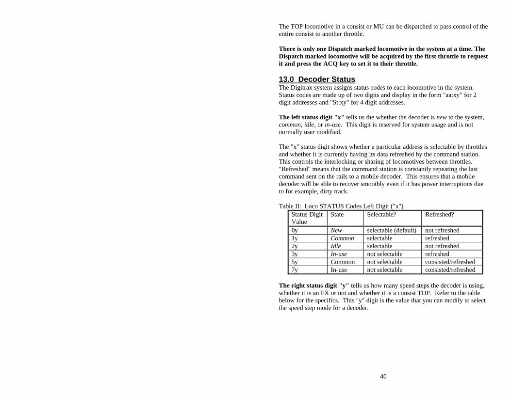
13.0 Decoder Status The Digitrax system assigns status codes to each locomotive in the system. Status codes are made up of two digits and display in the form "aa:xy" for 2 digit addresses and "St:xy" for 4 digit addresses. The left status digit "x" tells us the whether the decoder is new to the system, common, idle, or in-use. This digit is reserved for system usage and is not normally user modified. The "x" status digit shows whether a particular address is selectable by throttles and whether it is currently having its data refreshed by the command station. This controls the interlocking or sharing of locomotives between throttles. "Refreshed" means that the command station is constantly repeating the last command sent on the rails to a mobile decoder. This ensures that a mobile decoder will be able to recover smoothly even if it has power interruptions due to for example, dirty track. Table II: Loco STATUS Codes Left Digit ("x")
Status Digit Value
State Selectable? Refreshed?
0y New selectable (default) not refreshed 1y Common selectable refreshed 2y Idle selectable not refreshed 3y In-use not selectable refreshed 5y Common not selectable consisted/refreshed 7y In-use not selectable consisted/refreshed
The right status digit "y" tells us how many speed steps the decoder is using, whether it is an FX or not and whether it is a consist TOP. Refer to the table below for the specifics. This "y" digit is the value that you can modify to select the speed step mode for a decoder.
41
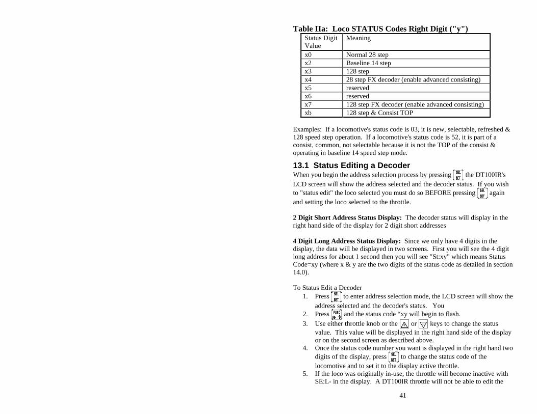
Table IIa: Loco STATUS Codes Right Digit ("y") Status Digit Value
Meaning
x0 Normal 28 step x2 Baseline 14 step x3 128 step x4 28 step FX decoder (enable advanced consisting) x5 reserved x6 reserved x7 128 step FX decoder (enable advanced consisting) xb 128 step & Consist TOP
Examples: If a locomotive's status code is 03, it is new, selectable, refreshed & 128 speed step operation. If a locomotive's status code is 52, it is part of a consist, common, not selectable because it is not the TOP of the consist & operating in baseline 14 speed step mode.
13.1 Status Editing a Decoder When you begin the address selection process by pressing the DT100IR's LCD screen will show the address selected and the decoder status. If you wish to "status edit" the loco selected you must do so BEFORE pressing again and setting the loco selected to the throttle. 2 Digit Short Address Status Display: The decoder status will display in the right hand side of the display for 2 digit short addresses 4 Digit Long Address Status Display: Since we only have 4 digits in the display, the data will be displayed in two screens. First you will see the 4 digit long address for about 1 second then you will see "St:xy" which means Status Code=xy (where x & y are the two digits of the status code as detailed in section 14.0).
To Status Edit a Decoder
1. Press to enter address selection mode, the LCD screen will show the address selected and the decoder's status. You
2. Press and the status code “xy will begin to flash.
3. Use either throttle knob or the or keys to change the status value. This value will be displayed in the right hand side of the display or on the second screen as described above.
4. Once the status code number you want is displayed in the right hand two digits of the display, press to change the status code of the locomotive and to set it to the display active throttle.
5. If the loco was originally in-use, the throttle will become inactive with SE:L- in the display. A DT100IR throttle will not be able to edit the
42
status of an in-use locomotive, it can only edit the status of a loco that is available for it to select.
6. If the loco was common, idle or new at the start of editing, the new status value will be loaded & the throttle will be activated on this locomotive when the key is pressed.
A consisted loco address cannot have its status edited. To edit the status for a consisted locomotive, the unit must be un-linked from the consist.
13.2 Note for Lenz, Marklin, MRC & Arnold Decoders If you have a decoder that does not understand Advanced 28/128 speed step mode, you must "status edit" that locomotive to Standard 14 speed step mode before running it with the DT100IR & the system. This tells the system to handle this decoder as a 14 step decoder. It does not reprogram anything in the locomotive. You will need to change the status code to a value of "x2", for example "12", so that the system will operate those decoders in Standard 14 speed step mode.
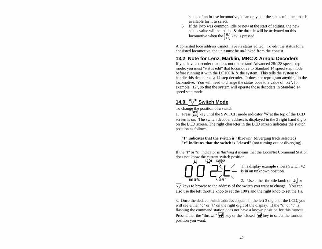
14.0 Switch Mode To change the position of a switch
1. Press key until the SWITCH mode indicator at the top of the LCD screen is on. The switch decoder address is displayed in the 3 right hand digits on the LCD screen. The right character in the LCD screen indicates the switch position as follows:
"t" indicates that the switch is "thrown" (diverging track selected) "c" indicates that the switch is "closed" (not turning out or diverging).
If the "t" or "c" indicator is flashing it means that the LocoNet Command Station does not know the current switch position.
This display example shows Switch #2 is in an unknown position. 2. Use either throttle knob or or
keys to browse to the address of the switch you want to change. You can also use the left throttle knob to set the 100's and the right knob to set the 1's. 3. Once the desired switch address appears in the left 3 digits of the LCD, you will see either "c" or "t" on the right digit of the display. If the "c" or "t" is flashing the command station does not have a known position for this turnout. Press either the "thrown" key or the "closed" key to select the turnout position you want.
43
NOTE: When Operating a DT100IR on Big Boy system, if your DT100IR detects that it is connected to system using a DT200 as the command station (Big Boy Starter Set) it will use the same 2 digit switch display mode as the DT200. Both left & right throttle knobs will only change the switch by 1 count to a maximum of 128 or "c8."
4. The switch you selected will change position from closed to thrown or vice-
versa. 5. After commanding the switch "closed" or "thrown" the switch position
display will stop flashing, since the command station now knows the current switch position.
Note that the switch decoders in the system are accessible to all throttles or control devices with switch control capabilities & are not reserved in-use to a single throttle like locomotive decoders are.
When you have finished your switch operations you can return to LOCO mode by: 1. Pressing the key twice (skipping past MU mode ) or 2. Wait for the 6 second no-input inactivity time-out to return the DT100IR to
the LOCO default mode. The next time you enter SWITCH mode , the DT100IR will remember where you left off & start at the last switch address & position you accessed.
15.0 Multiple Unit Operations: The DB150 command station offers two methods of consist control: 1. The BASIC Consisting method is to reprogram all the locomotives in a
consist to the same address and run them off one throttle. In this case all the locomotives must be headed in the same direction, head to tail, head to tail, head to tail. You probably won't use this method very often in your operations because of its limitations. The Basic method is the only method available to most basic command stations. We mention it here only because it is an option.
2. The UniVersal Consisting method is handled by the command station and allows you to consist locomotives with any DCC format decoder as well as an analog loco. The locomotives can be added to and deleted from the consist in any orientation, head to head or tail to tail. This method has the advantage of being able to use all decoders in consists.
You can add a locomotive to a consist in either direction and in any physical location in the train. When you send commands to the consist you use a single address and the command station or decoders handle the rest of the commands to the other locomotives in the consist. Since the address you will use to control the consist is not necessarily the address of the lead or head loco we have chosen the term "TOP" locomotive for this special address. We always add or MU
44
LINK a loco to the "TOP" loco of a consist. The "TOP" loco is special, in that it is the address that receives the speed & overall direction commands for the entire consist and all other locomotive's added or linked into the consist will be controlled by running the "TOP" loco on a single throttle knob. The TOP locomotive does not even have to be a physical loco on the track, it can be a phantom. The TOP loco is always defined as the loco on the Right Throttle Knob at the time when the MU-Link is performed.
Consists are controlled through the TOP locomotive & all locomotive's in the consist will be common, in-use or idle based on the state of the TOP loco. Each loco within a consist maintains its original Advanced 28/128 or Standard 14 speed step mode setting. To run a loco in a consist with loadable speed tables, set the locomotive status for Advanced 28/128 speed step mode & program the decoder to operate with the loadable speed table enabled. See your decoder manual for information about programming loadable speed tables. If you are operating FX decoders, the Loadable table can be used in 128 step mode. A consist can be made common and then be selected and run by any other throttle. A consist can also be dispatched and picked up on a different throttle. See section 13.0
15.1 MU-Link: Adding a Locomotive To A Consist To set up a consist using your DT100IR throttle: 1. Select and Set the address of the loco you want to be the TOP loco on the
Right Throttle Knob "R". Remember that you can use any 2 digit short address, 4 digit long address and/or an analog locomotive running on Address 00 in any combination.
2. Select and Set the address of the loco you want to consist to the TOP loco on the Left Throttle Knob "L".
3. Move the two locomotives into position. The locomotives can be headed in either direction. They can be adjacent to each other in the train or one unit can be the mid train helper or a pusher on the end of the train.
4. Before consisting the locomotives together make sure that both are traveling in the SAME PHYSICAL DIRECTION ON THE TRACK. (The direction indicators may or may not match, the important thing is that the locomotives are traveling in the same direction and are not pulling against each other.)
5. Press the key until the MU mode indicator on the LCD display is lit. If both throttles are running 2 digit short addresses, the left-hand side of the display shows the loco address active on the Left Throttle Knob "L" & the right-hand side of the display shows the loco address active on the Right Throttle Knob "R" (The TOP Loco). The LCD displays are slightly different when performing MU operations with 4 digit long addresses .In this case all the operations are performed with the same key-strokes & have the same meanings as for 2 digit short addresses. When you enter MU mode, before
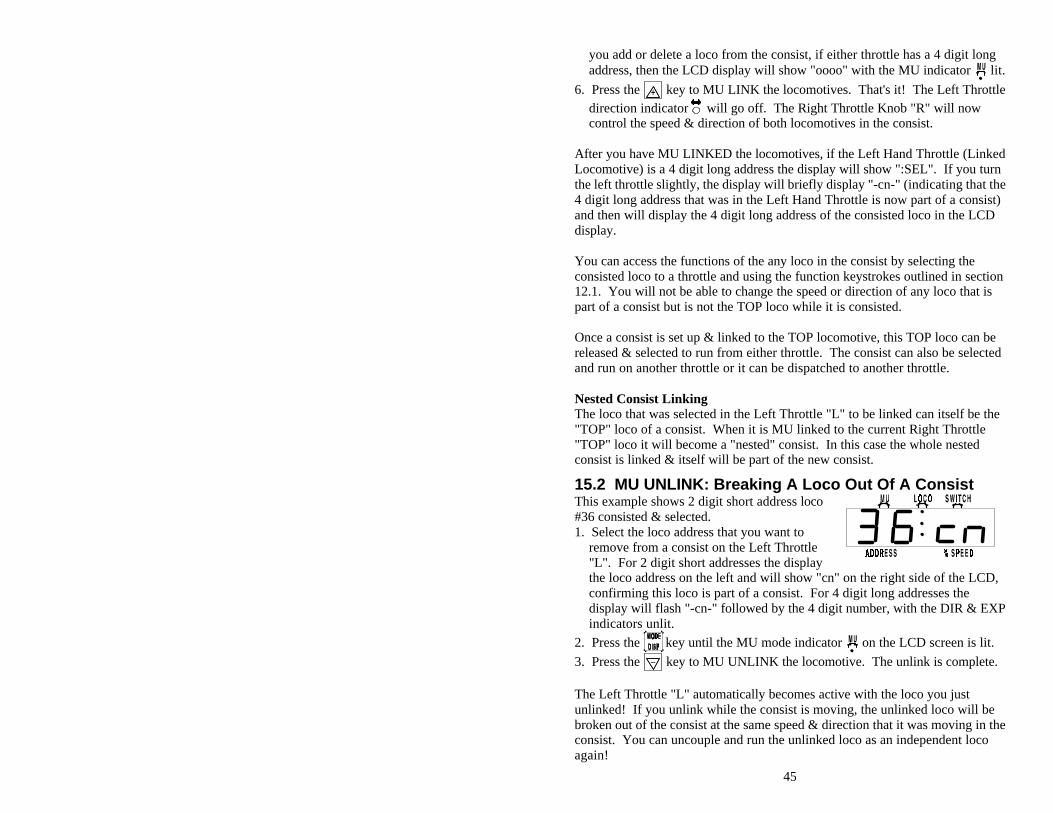
45
you add or delete a loco from the consist, if either throttle has a 4 digit long address, then the LCD display will show "oooo" with the MU indicator lit.
6. Press the key to MU LINK the locomotives. That's it! The Left Throttle direction indicator will go off. The Right Throttle Knob "R" will now control the speed & direction of both locomotives in the consist.
After you have MU LINKED the locomotives, if the Left Hand Throttle (Linked Locomotive) is a 4 digit long address the display will show ":SEL". If you turn the left throttle slightly, the display will briefly display "-cn-" (indicating that the 4 digit long address that was in the Left Hand Throttle is now part of a consist) and then will display the 4 digit long address of the consisted loco in the LCD display. You can access the functions of the any loco in the consist by selecting the consisted loco to a throttle and using the function keystrokes outlined in section 12.1. You will not be able to change the speed or direction of any loco that is part of a consist but is not the TOP loco while it is consisted. Once a consist is set up & linked to the TOP locomotive, this TOP loco can be released & selected to run from either throttle. The consist can also be selected and run on another throttle or it can be dispatched to another throttle.
Nested Consist Linking The loco that was selected in the Left Throttle "L" to be linked can itself be the "TOP" loco of a consist. When it is MU linked to the current Right Throttle "TOP" loco it will become a "nested" consist. In this case the whole nested consist is linked & itself will be part of the new consist.
15.2 MU UNLINK: Breaking A Loco Out Of A Consist This example shows 2 digit short address loco #36 consisted & selected. 1. Select the loco address that you want to
remove from a consist on the Left Throttle "L". For 2 digit short addresses the display the loco address on the left and will show "cn" on the right side of the LCD, confirming this loco is part of a consist. For 4 digit long addresses the display will flash "-cn-" followed by the 4 digit number, with the DIR & EXP indicators unlit.
2. Press the key until the MU mode indicator on the LCD screen is lit.
3. Press the key to MU UNLINK the locomotive. The unlink is complete.
The Left Throttle "L" automatically becomes active with the loco you just unlinked! If you unlink while the consist is moving, the unlinked loco will be broken out of the consist at the same speed & direction that it was moving in the consist. You can uncouple and run the unlinked loco as an independent loco again!
46
15.2.1 Nested Consist Unlinking The loco that is selected in the Left Hand Throttle to be unlinked can itself be the "Top" loco of a nested consist that was linked into the current Right throttle "Top" loco. In this case the whole nested consist is unlinked & returned to the Left Throttle as a consist.
15.3 MU of Mismatched Locomotives If all the locomotives in the consist have performance characteristics that are closely matched, you can run all the consisted locomotives in 128 step mode. If the units are completely mismatched (for example if you are running an Athearn with a Kato), then we recommend programming the decoders using the User Loadable Speed Table (See section 19.5) & running the DT100IR in the 28 step mode to achieve better speed matching of locomotives in the consist. This lets you speed match the 28 step operation of each locomotive to a given reference locomotive, so when they are consisted they will run well together. If you want to consist with a conventional analog locomotive, use the analog locomotive as the reference locomotive & match the DCC locomotives to it using the User Loadable Speed Table. If you are using FX type decoders then you can use the Loadable Speed tables in 128 step mode for really superior speed control & matching in MU's or consists.
16.0 DT100IR Configuration Options The DT100IR has an individual throttle OPTION mode that lets you customize your throttle. The options are assigned as hexadecimal numbers representing combinations of options as shown in the tables below. The default values are generally satisfactory for most operations. NOTE: It is recommended that all locomotives assigned to this throttle be released before you change any options. 1. Unplug the DT100IR from the network. Press and hold the "SEL/SET"
button and plug the DT100IR back into the network. The display will show the Primary Throttle Option Screen "oP:01" (default). This display will appear for approx. 5 seconds if no action is taken, if no action is taken after 5 seconds, the DT100IR will return to "RUN" mode
2. 2. While "oP:nn" is still in the display, use the throttle knobs "R or L" to modify the Primary option value according to the following table:
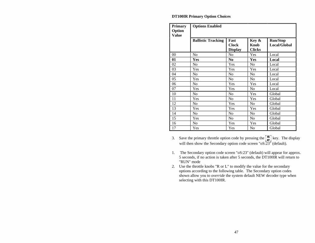
47
DT100IR Primary Option Choices Primary Option Value
Options Enabled
Ballistic Tracking Fast Clock Display
Key & Knob Clicks
Run/Stop Local/Global
00 No No Yes Local 01 Yes No Yes Local 02 No Yes No Local 03 Yes Yes Yes Local 04 No No No Local 05 Yes No No Local 06 No Yes Yes Local 07 Yes Yes No Local 10 No No Yes Global 11 Yes No Yes Global 12 No Yes No Global 13 Yes Yes Yes Global 14 No No No Global 15 Yes No No Global 16 No Yes Yes Global 17 Yes Yes No Global 3. Save the primary throttle option code by pressing the key. The display will then show the Secondary option code screen "oS:23" (default). 1. The Secondary option code screen "oS:23" (default) will appear for approx.
5 seconds, if no action is taken after 5 seconds, the DT100IR will return to "RUN" mode
2. Use the throttle knobs "R or L" to modify the value for the secondary options according to the following table. The Secondary option codes shown allow you to override the system default NEW decoder type when selecting with this DT100IR.
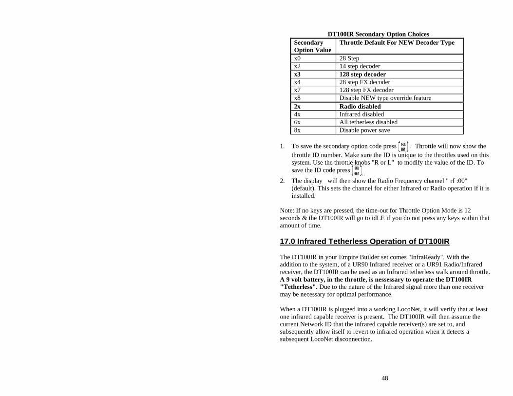
48
DT100IR Secondary Option Choices
Secondary Option Value
Throttle Default For NEW Decoder Type
x0 28 Step x2 14 step decoder x3 128 step decoder x4 28 step FX decoder x7 128 step FX decoder x8 Disable NEW type override feature 2x Radio disabled 4x Infrared disabled 6x All tetherless disabled 8x Disable power save
1. To save the secondary option code press . Throttle will now show the
throttle ID number. Make sure the ID is unique to the throttles used on this system. Use the throttle knobs "R or L" to modify the value of the ID. To save the ID code press ..
2. The display will then show the Radio Frequency channel " rf :00" (default). This sets the channel for either Infrared or Radio operation if it is installed.
Note: If no keys are pressed, the time-out for Throttle Option Mode is 12 seconds & the DT100IR will go to idLE if you do not press any keys within that amount of time.
17.0 Infrared Tetherless Operation of DT100IR The DT100IR in your Empire Builder set comes "InfraReady". With the addition to the system, of a UR90 Infrared receiver or a UR91 Radio/Infrared receiver, the DT100IR can be used as an Infrared tetherless walk around throttle. A 9 volt battery, in the throttle, is nessessary to operate the DT100IR "Tetherless". Due to the nature of the Infrared signal more than one receiver may be necessary for optimal performance. When a DT100IR is plugged into a working LocoNet, it will verify that at least one infrared capable receiver is present. The DT100IR will then assume the current Network ID that the infrared capable receiver(s) are set to, and subsequently allow itself to revert to infrared operation when it detects a subsequent LocoNet disconnection.
49
17.1 LocoNet Connection On connection to a LocoNet that has compatible infrared capability, the DT100IR LCD display will flash the infrared status code “rA:0n” the number “n” signifies the LocoNet ID being used by all receiver’s on the system it has plugged into and will be identifying itself with. The display will then revert to normal DT100 tethered operation displays and actions. If the system does not have a UR90 or equivalent device, the DT100IR will not display the “rA:--“ message to show that it cannot operate “Tetherless” on that system and thus not allow the infrared to be active when untethered.
17.2 Display power down When the DT100IR has connected to a LocoNet and received the LocoNet ID number it will allow tetherless operation of locomotives that have been selected into either throttle knob. If an untethered DT100IR detects no user throttle activity for about 3 minutes it will enter Power Saver mode and display on the LCD the infrared status code “r- PS” until a throttle or key action restores normal activity and displays. If the DT100IR has a locomotive assigned to it and is in Power Saver Mode, it will continue to “check in” with the system every 60 seconds telling the system “Hey I’m still here”. This keeps the system from releasing that locomotive back to “common”. The direction LED’s of active throttles may blink every 1.5 seconds when the DT100IR is checking to see if any new key or encoder input has been made. It may be most convenient to hold down either the or key to signal the unit to exit from power saver mode. You can use the Secondary option to turn off Power Saver mode, see section 17.0. If you wish to have the infrared throttle enter the lowest power use “idLE” state of a normal DT100, then you can connect it to a LocoNet in sleep mode. If the LocoNet is in sleep and has battery saver capability then the DT100IR can take all its power indefinitely from the LocoNet. Alternatively, you may reset the DT100IR by simultaneously pressing the , and keys , as detailed in the DT100 instructions. Once the DT100IR is reset it remains “idLE” and cannot become an active infrared throttle until it has been reconnected to a infrared capable LocoNet and has an active address selected. Of course, you may simply remove the DT100IR battery to power down an untethered DT100IR. If you use Power Saver mode then the DT100IR’s local Fast clock copy will deviate from the System value. It will resynchronize with the system when reconnected.
50
17.3 LocoNet ID change In normal operations a DT100IR will accept and use the LocoNet ID offered by the compatible infrared receiver(s) it may see when connected to the network. To allow a LocoNet to be changed to a different ID number, to allow for example 2 clubs to have layouts at the same show, the DT100IR may be used to change the LocoNet ID number of one of the independent LocoNet systems. To change a LocoNet ID number: 1) Disconnect a DT100IR from the LocoNet that you wish to modify the ID. 2) Press and hold down the MODE/DISP key on the DT100IR and then reconnect the unit to the LocoNet. This key being active upon reconnect enables the DT100IR to be allowed to modify the system ID. 3) Release the MODE/DISP key. The DT100IR will flash up the current infrared ID# “rA:0n”, where the “n” digit shows the current LocoNet ID. Use RIGHT HAND THROTTLE to change the ID digit “n” to that desired, in the range 0 to 7, and then press the SEL/SET key to set the system to the new ID. 4) Be sure to reconnect any DT100IR that is going to be used on this system back to the system so it can adopt the new ID number and be able to access the new system ID. If you add a new UR90 or UR91 to the system and are using a LocoNet ID other than the initial default value of 0, you need to re-synchronize the ID's in all the UR90's and UR91's following the outlined steps above with a new ID for the whole system If you are operating in a large group or meet with several different LocoNet systems nearby, be sure to issue a new and unique ID to each system before beginning operations.
17.4 “Tetherless” Operation Selecting a Locomotive While tetherless, the DT100IR operates as a one-way transmitter and uses its cable connection to establish initial locomotive address selection. The DT100IR must be plugged into LocoNet to select an available locomotive address. After a DT100IR has selected a locomotive, it may then be unplugged from the network and will automatically revert to infrared operation for all subsequent, speed, direction, function and turnout commands. Releasing a Locomotive When working untethered with an active address in the LCD display, if the SEL/SET key is pressed the locomotive address will immediately be released as common in the system and that throttle will become inactive. To re-select this locomotive you will then need to reconnect to the LocoNet. The DT100IR will
51
automatically reselect that locomotive when the DT100IR is connected to the network providing that the status of that locomotive remains in common Multiple Unit Operations Consists may be assembled and broken up in the normal fashion while the DT100IR is connected to LocoNet, however, the M.U. function is locked out while the DT100IR is being used Tetherless. Once a consist is made up, it may be operated normally using the DT100IR “Tetherless”. Operations Mode Programming Operation Mode Programming or OPS mode will work only while the DT100IR is connected to LocoNet. Service Mode Programming The DT100IR must be connected to LocoNet to use it’s Service Mode Programming Mode. Switch Mode The DT100IR will operate in the “Switch” Mode while “Tetherless”. It can throw switches and routes using the “t” and “c” buttons in the normal manner. Ballistic Tracking While running “Tetherless” Ballistic Tracking will feel slightly different than while connected to LocoNet. Fast Clock When using the Fast Clock option, the DT100IR will keep track of and display Fast Time based on what the Fast Time was the last time the DT100IR was connected to LocoNet. If the Fast Time is edited by someone else connected to the network, the DT100IR will not see this change until it is plugged into LocoNet at which time it’s display will be updated.
17.5 Battery “Fuel Gauge” The DT100IR continually checks the voltage of the battery while running “Tetherless”. If it detects a voltage in the questionable range, around 6.8 volts, the DT100IR will beep twice in about one second and display “bt:nn” on the LCD. The “n” is the number of times the warning has sounded. The warning will continue every 5 min. until the battery is changed. The display will disappear when any control is activated. Don’t Panic when this warning appears. The DT100IR will continue to function normally for an extended period of time depending on the type battery in use. 9 volt alkaline batteries are nearing the end of their life at this voltage, but 7.2 volt NiCad rechargeable batteries may still have lots of life remaining. Experience will determine how long your DT100IR will operate after the warning has sounded. The counter in the display is a useful tool in determining how long your battery will last. The
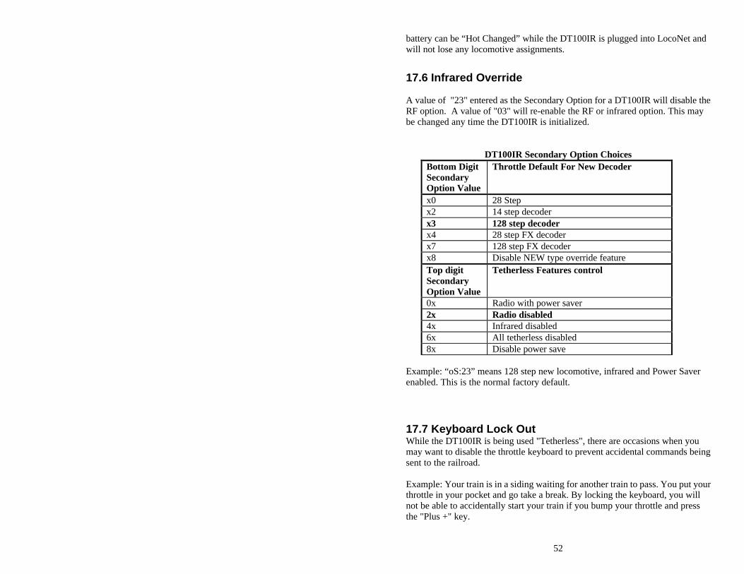
52
battery can be “Hot Changed” while the DT100IR is plugged into LocoNet and will not lose any locomotive assignments.
17.6 Infrared Override A value of "23" entered as the Secondary Option for a DT100IR will disable the RF option. A value of "03" will re-enable the RF or infrared option. This may be changed any time the DT100IR is initialized.
DT100IR Secondary Option Choices Bottom Digit Secondary Option Value
Throttle Default For New Decoder
x0 28 Step x2 14 step decoder x3 128 step decoder x4 28 step FX decoder x7 128 step FX decoder x8 Disable NEW type override feature Top digit Secondary Option Value
Tetherless Features control
0x Radio with power saver 2x Radio disabled 4x Infrared disabled 6x All tetherless disabled 8x Disable power save
Example: “oS:23” means 128 step new locomotive, infrared and Power Saver enabled. This is the normal factory default.
17.7 Keyboard Lock Out While the DT100IR is being used "Tetherless", there are occasions when you may want to disable the throttle keyboard to prevent accidental commands being sent to the railroad. Example: Your train is in a siding waiting for another train to pass. You put your throttle in your pocket and go take a break. By locking the keyboard, you will not be able to accidentally start your train if you bump your throttle and press the "Plus +" key.
53
To lock the keyboard on your DT100IR, simply press both the "PLUS +" and the "MINUS -" keys at the same time. The throttle will display "Locd" in the display and none of the controls will function. To un-lock the keyboard simply press both the "PLUS +" and the "MINUS -" keys at the same time again. This will return the throttle to normal operation. Plugging the throttle into LocoNet will also unlock the throttle.
18.0 Programming and Configuration Your DCC Decoders have many different Configuration Variables (CV's for short) that let you set up a different set of operating characteristics for each decoder installed in each locomotive. Each of these CV's controls a characteristic of the decoder. See Table III for a list of the most commonly used CV's and their meanings. Each decoder comes pre-programmed from the factory with the default settings outlined in your decoder manual. You can change your decoder's performance characteristics by choosing from among the CV's and setting up each one independently. Each of these CV's can be set up when your command station is in the programming mode or by using the Digitrax PR-1 Computer Programmer & your PC. The CV's are remembered in the decoder until it is reprogrammed to a new value. Please refer to your Mobile Decoder Manual for a complete listing of the CV's supported by each decoder. It is a good idea to run your decoders with the default values that come pre programmed in your decoders until you get used to the system & what it can do for you. Then you can begin customizing. Initially, we recommend that you keep deceleration values small. This will let you adapt to the delays in deceleration you have programmed without crashing your valuable locomotives! The DB150 command station sends programming information to the decoders through the rails. This information is sent as a broadcast message to any decoder that is listening. This means that you could reprogram all the locomotives on the layout with one keystroke. (See section 4.2 Separate Programming Track) When the DB150 receives a programming command from any throttle on the Network, it shuts down any boosters connected to it and stops all locomotives. The DB150 then sends the programming command to any decoder on the track directly connected to the DB150 command station. The DB150 beeps once to indicate that it has sent the programming command. Track under the control of other expansion boosters will not receive the command.
54
18.1 How to Program 2 Digit Addresses 1. Be sure that only the loco you want to program is on the programming
track. 2. Press and hold then press at the same time to enter programming
mode. 3. The DT100IR's green PROG indicator will come on, letting you
know that you are in programming mode. 4. The LCD will flash the word "PagE", letting you know that you are in
paged mode. This is the preferred method of programming for all Digitrax decoders. If your display does not show "PagE", press the FUNC key to move through the programming methods until "PagE" shows in your display.
5. The LCD will display AD:--. Turn the Right Throttle knob "R" on the DT100IR until the address number you want to use for the loco is displayed in the right hand side of the LCD screen.
6. Press the key to "SET" the address of the decoder to the value showing in the right side of the display. If programming was successful, the DT100IR will flash "Good". The DT100IR will then display AD: followed by the two digit address you just programmed to the decoder.
7. Press and hold then press at the same time to exit programming mode. The LCD will Show SE:L-.
8. To select and run the loco, turn the left or right throttle 1/4 turn to activate it, press the key, dial up the address you want to run and press the key again to SET the address to the throttle.
9. After you do any programming, the first time you select a loco to run, the system will turn off track power. Simply press and hold the key then press the key while continuing to hold the Run/Stop Key. Release both keys when the system beeps and you see the lights on the DT100IR change from steady ORANGE.
18.2 How to Program Four Digit Addresses Automated Programming of CV18 & CV17 To Set Up 4 Digit Addresses 1. Place the locomotive with 4 digit capable decoder on the programming
track. 2. Enter Program Mode by holding down & pressing at the same
time. If your display does not show "PagE", press the FUNC key to move through the programming methods until "PagE" shows in your display.
3. Use the DT100IR's Left Throttle Knob "L" to select CV18 in the left 2 digits of the display.
4. Press the key. This starts the 4 digit sequence. Before you make any
changes, press the key again to force the DT100IR to look at both V17 and CV18 at the same time. All four digits in the display will be flashing.
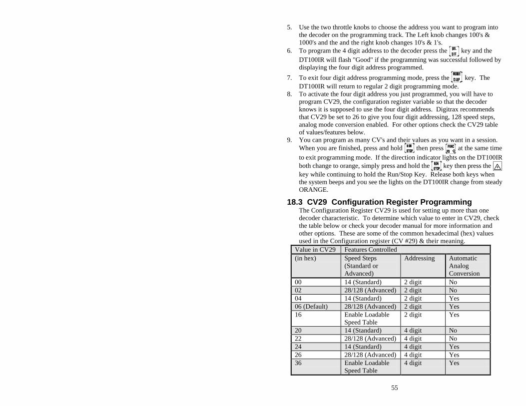
55
5. Use the two throttle knobs to choose the address you want to program into the decoder on the programming track. The Left knob changes 100's & 1000's and the and the right knob changes 10's & 1's.
6. To program the 4 digit address to the decoder press the key and the DT100IR will flash "Good" if the programming was successful followed by displaying the four digit address programmed.
7. To exit four digit address programming mode, press the key. The DT100IR will return to regular 2 digit programming mode.
8. To activate the four digit address you just programmed, you will have to program CV29, the configuration register variable so that the decoder knows it is supposed to use the four digit address. Digitrax recommends that CV29 be set to 26 to give you four digit addressing, 128 speed steps, analog mode conversion enabled. For other options check the CV29 table of values/features below.
9. You can program as many CV's and their values as you want in a session. When you are finished, press and hold then press at the same time
to exit programming mode. If the direction indicator lights on the DT100IR both change to orange, simply press and hold the key then press the key while continuing to hold the Run/Stop Key. Release both keys when the system beeps and you see the lights on the DT100IR change from steady ORANGE.
18.3 CV29 Configuration Register Programming The Configuration Register CV29 is used for setting up more than one decoder characteristic. To determine which value to enter in CV29, check the table below or check your decoder manual for more information and other options. These are some of the common hexadecimal (hex) values used in the Configuration register (CV #29) & their meaning.
Value in CV29 Features Controlled (in hex) Speed Steps
(Standard or Advanced)
Addressing Automatic Analog Conversion
00 14 (Standard) 2 digit No 02 28/128 (Advanced) 2 digit No 04 14 (Standard) 2 digit Yes 06 (Default) 28/128 (Advanced) 2 digit Yes 16 Enable Loadable
Speed Table 2 digit Yes
20 14 (Standard) 4 digit No 22 28/128 (Advanced) 4 digit No 24 14 (Standard) 4 digit Yes 26 28/128 (Advanced) 4 digit Yes 36 Enable Loadable
Speed Table 4 digit Yes
56
Note that with Digitrax Standard Decoders (non FX decoders), if 128 speed steps are sent by the command station then the 14/28 speed step & Loadable speed table selections are not used.
18.4 How to Program Other Configuration Variables There are many different CVs that have been defined to handle many characteristics you might want to use for your locomotives. Table III below contains a list of the CVs used most often. Your decoder manual has a complete listing of CVs, what they do and suggested values for each CV. 1. Be sure that only the loco you want to program is on the programming
track. 2. Press and hold then press at the same time to enter programming
mode. 3. The DT100IR's green PROG indicator will come on, letting you
know that you are in programming mode. 4. The LCD will flash the word "PagE", letting you know that you are in
paged mode. This is the preferred method of programming for all Digitrax decoders. If your display does not show "PagE", press the FUNC key to move through the programming methods until "PagE" shows in your display.
5. The LCD will display AD:--. 6. Turn the Left Throttle knob "L" on the DT100IR until the CV # you want to
program appears on the left side of the LCD. 7. Turn the Right Throttle Knob "R" until the value you want to program into
that CV appears in the right side of the LCD. 8. Press the key to set the values selected. 9. You can program as many CV's and their values as you want in a session.
When you are finished, press and hold then press at the same time
to exit programming mode. If the direction indicator lights on the DT100IR both change to orange, simply press and hold the key then press the key while continuing to hold the Run/Stop Key. Release both keys when the system beeps and you see the lights on the DT100IR change from steady ORANGE.
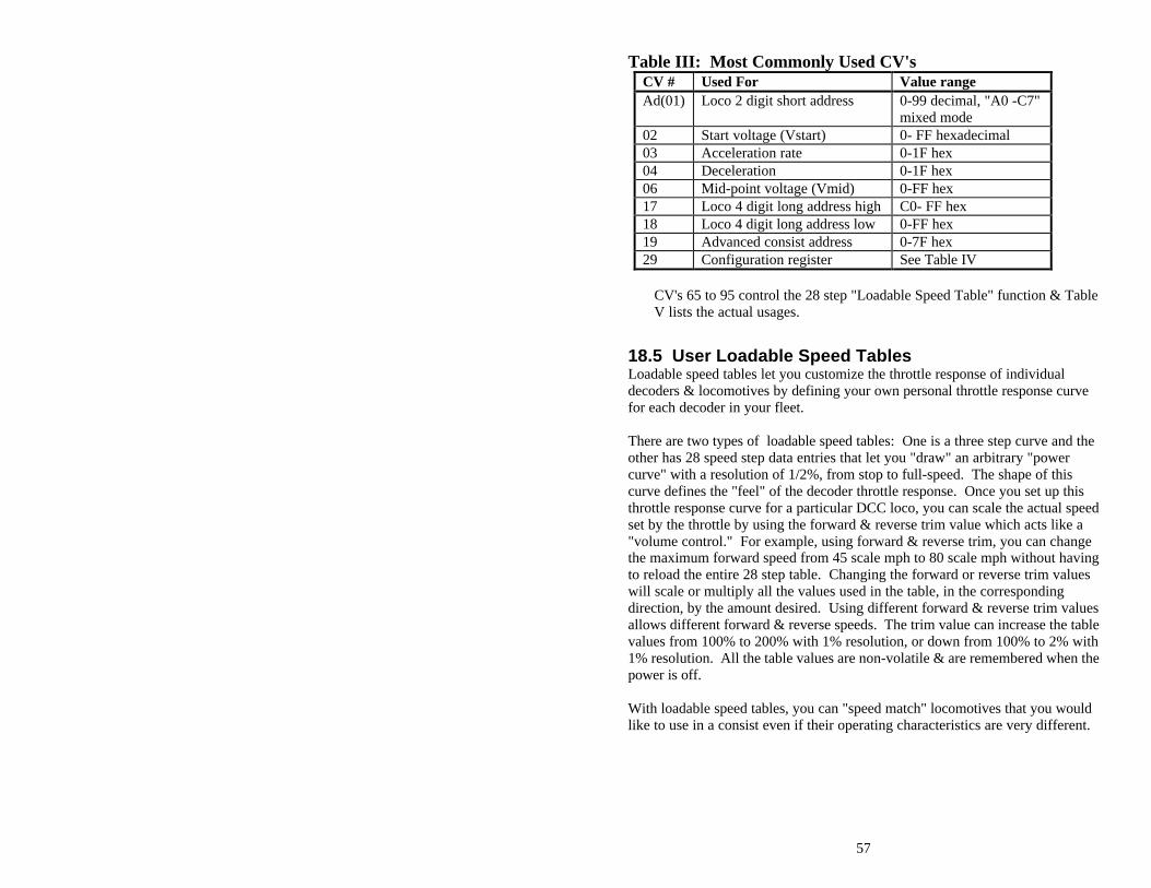
57
Table III: Most Commonly Used CV's CV # Used For Value range Ad(01) Loco 2 digit short address 0-99 decimal, "A0 -C7"
mixed mode 02 Start voltage (Vstart) 0- FF hexadecimal 03 Acceleration rate 0-1F hex 04 Deceleration 0-1F hex 06 Mid-point voltage (Vmid) 0-FF hex 17 Loco 4 digit long address high C0- FF hex 18 Loco 4 digit long address low 0-FF hex 19 Advanced consist address 0-7F hex 29 Configuration register See Table IV
CV's 65 to 95 control the 28 step "Loadable Speed Table" function & Table V lists the actual usages.
18.5 User Loadable Speed Tables Loadable speed tables let you customize the throttle response of individual decoders & locomotives by defining your own personal throttle response curve for each decoder in your fleet. There are two types of loadable speed tables: One is a three step curve and the other has 28 speed step data entries that let you "draw" an arbitrary "power curve" with a resolution of 1/2%, from stop to full-speed. The shape of this curve defines the "feel" of the decoder throttle response. Once you set up this throttle response curve for a particular DCC loco, you can scale the actual speed set by the throttle by using the forward & reverse trim value which acts like a "volume control." For example, using forward & reverse trim, you can change the maximum forward speed from 45 scale mph to 80 scale mph without having to reload the entire 28 step table. Changing the forward or reverse trim values will scale or multiply all the values used in the table, in the corresponding direction, by the amount desired. Using different forward & reverse trim values allows different forward & reverse speeds. The trim value can increase the table values from 100% to 200% with 1% resolution, or down from 100% to 2% with 1% resolution. All the table values are non-volatile & are remembered when the power is off. With loadable speed tables, you can "speed match" locomotives that you would like to use in a consist even if their operating characteristics are very different.
58
To Program A 28 Step Loadable Speed Table: 1. Be sure that only the loco you want to program is on the programming
track. 2. Press and hold then press at the same time to enter programming
mode. 3. The DT100IR's green PROG indicator will come on, letting you
know that you are in programming mode. 4. The LCD will flash the word "PagE", letting you know that you are in
paged mode. This is the preferred method of programming for all Digitrax decoders. If your display does not show "PagE", press the FUNC key to move through the programming methods until "PagE" shows in your display.
5. The LCD will display AD:--. 6. Turn the Left Throttle knob "L" on the DT100IR until the "65" appears on
the left side of the LCD. 7. If you want to use a 3 step table, just program Vstart CV02, Vmid
CV06 & V-max CV94. 8. Turn the Right Throttle Knob "R" until the value you want to program into
CV65 appears in the right side of the LCD. 9. Press the key to set the values selected. 10. Turn the Left Throttle Knob until "66" appears in the loft side of the LCD.
Turn the Right Throttle Knob until the value you want to program for CV66 shows in the right side of the LCD. Press SEL/SET to program CV66 to the chosen value.
11. Continue programming all CVs from 65 through 96 as above. 12. Program CV29 to a value of 10-19 or 30-39 (see the table above to
determine the value you want to use. 13. You can program as many CV's and their values as you want in a session.
When you are finished, press and hold then press at the same time
to exit programming mode. If the direction indicator lights on the DT100IR both change to orange, simply press and hold the key then press the key while continuing to hold the Run/Stop Key. Release both keys when the system beeps and you see the lights on the DT100IR change from steady ORANGE.
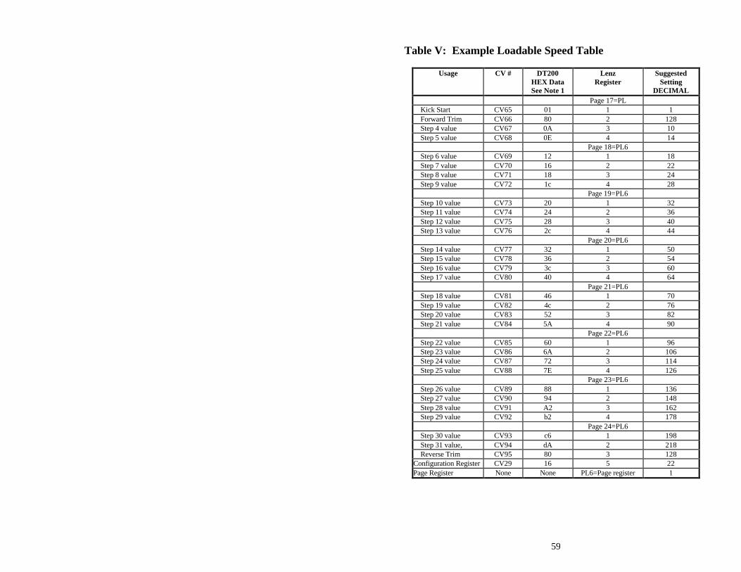
59
Table V: Example Loadable Speed Table
Usage CV # DT200 HEX Data See Note 1
Lenz Register
Suggested Setting
DECIMAL Page 17=PL
Kick Start CV65 01 1 1 Forward Trim CV66 80 2 128 Step 4 value CV67 0A 3 10 Step 5 value CV68 0E 4 14 Page 18=PL6 Step 6 value CV69 12 1 18 Step 7 value CV70 16 2 22 Step 8 value CV71 18 3 24 Step 9 value CV72 1c 4 28 Page 19=PL6 Step 10 value CV73 20 1 32 Step 11 value CV74 24 2 36 Step 12 value CV75 28 3 40 Step 13 value CV76 2c 4 44 Page 20=PL6 Step 14 value CV77 32 1 50 Step 15 value CV78 36 2 54 Step 16 value CV79 3c 3 60 Step 17 value CV80 40 4 64 Page 21=PL6 Step 18 value CV81 46 1 70 Step 19 value CV82 4c 2 76 Step 20 value CV83 52 3 82 Step 21 value CV84 5A 4 90 Page 22=PL6 Step 22 value CV85 60 1 96 Step 23 value CV86 6A 2 106 Step 24 value CV87 72 3 114 Step 25 value CV88 7E 4 126 Page 23=PL6 Step 26 value CV89 88 1 136 Step 27 value CV90 94 2 148 Step 28 value CV91 A2 3 162 Step 29 value CV92 b2 4 178 Page 24=PL6 Step 30 value CV93 c6 1 198 Step 31 value, CV94 dA 2 218 Reverse Trim CV95 80 3 128 Configuration Register CV29 16 5 22 Page Register None None PL6=Page register 1
60
Notes for Table V: 1. The DT100IR uses hexadecimal numbers for the data to be stored in all CV's
except the address CV (CV#1). Table VI shows how hexadecimal numbers correspond to regular decimal numbers.
2. Kick Start gives a short voltage "kick" when you start the locomotive decoder from 0 speed. A value of 0 turns this OFF. Experiment with values for a particular installation to find the best compromise.
3. Forward Trim (CV66) & Reverse Trim (CV95) values of 128 (80 Hex) will yield a scaling of 100%. The same effect will occur if the value 0 or 1 is loaded for Forward or Reverse Trim, i.e., Multiply by exactly 1. A Trim value of 255 (FF Hex) will give 200% scaling of the table entry value.
4. A scaled table value of 255 (FF Hex) represents 100% applied motor voltage or full speed. A value of 128 (80 Hex) represents 50% applied motor voltage, i.e., the actual table step entry is multiplied by the appropriate Trim value to yield the final scaled table value that defines the voltage to apply to the motor.
5. The Steps defined in the table are for the NMRA 28 step mode. Step 4 is the first motion step in the 28 Speed step system. Step 31 is the "full throttle" speed step. When configuring the decoder to run 14 step mode, only every second entry is used, the decoder automatically uses the correct data value.
6. The suggested data values given in the table will give a throttle response curve that most US users are comfortable with. The data values can be modified to suit your individual preferences.
Note that if the Configuration Register is set up with the User Loadable Speed Table flag SET (CV29 set to 16 or 36) to enable the Speed Table, the VSTART & VMID values are not used to by the decoder when calculating Loadable Speed Table values.
Many Digitrax customers have asked us why we can't formulate tables like this one for the specific locomotives that they are running. The reason for this is that each & every locomotive is different. If we bought 5 identical brand new locomotives today & put them on the test track, we would probably find that they do not all run exactly the same way. And, as time goes on & we run these locomotives for different amounts of time under different sets of circumstances they will probably change even more. It's really best to start with the default table shown & work with your own equipment to customize it for your own preferences. If you are planning to do a lot of customizing, the PR-1 is probably an easier solution for setting up loadable speed tables.
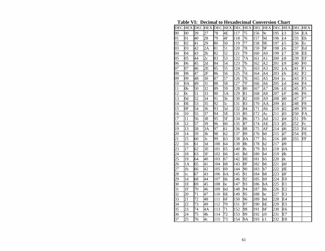
61
Table VI: Decimal to Hexadecimal Conversion Chart
DEC HEX DEC HEX DEC HEX DEC HEX DEC HEX DEC HEX DEC HEX 00 00 39 27 78 4E 117 75 156 9c 195 c3 234 EA 01 01 40 28 79 4F 118 76 157 9d 196 c4 235 Eb 02 02 41 29 80 50 119 77 158 9E 197 c5 236 Ec 03 03 42 2A 81 51 120 78 159 9F 198 c6 237 Ed 04 04 43 2b 82 52 121 79 160 A0 199 c7 238 EE 05 05 44 2c 83 53 122 7A 161 A1 200 c8 239 EF 06 06 45 2d 84 54 123 7b 162 A2 201 c9 240 F0 07 07 46 2E 85 55 124 7c 163 A3 202 cA 241 F1 08 08 47 2F 86 56 125 7d 164 A4 203 cb 242 F2 09 09 48 30 87 57 126 7E 165 A5 204 cc 243 F3 10 0A 49 31 88 58 127 7F 166 A6 205 cd 244 F4 11 0b 50 32 89 59 128 80 167 A7 206 cE 245 F5 12 0c 51 33 90 5A 129 81 168 A8 207 cF 246 F6 13 0d 52 34 91 5b 130 82 169 A9 208 d0 247 F7 14 0E 53 35 92 5c 131 83 170 AA 209 d1 248 F8 15 0F 54 36 93 5d 132 84 171 Ab 210 d2 249 F9 16 10 55 37 94 5E 133 85 172 Ac 211 d3 250 FA 17 11 56 38 95 5F 134 86 173 Ad 212 d4 251 Fb 18 12 57 39 96 60 135 87 174 AE 213 d5 252 Fc 19 13 58 3A 97 61 136 88 175 AF 214 d6 253 Fd 20 14 59 3b 98 62 137 89 176 b0 215 d7 254 FE 21 15 60 3c 99 63 138 8A 177 b1 216 d8 255 FF 22 16 61 3d 100 64 139 8b 178 b2 217 d9 23 17 62 3E 101 65 140 8c 179 b3 218 dA 24 18 63 3F 102 66 141 8d 180 b4 219 db 25 19 64 40 103 67 142 8E 181 b5 220 dc 26 1A 65 41 104 68 143 8F 182 b6 221 dd 27 1b 66 42 105 69 144 90 183 b7 222 dE 28 1c 67 43 106 6A 145 91 184 b8 223 dF 29 1d 68 44 107 6b 146 92 185 b9 224 E0 30 1E 69 45 108 6c 147 93 186 bA 225 E1 31 1F 70 46 109 6d 148 94 187 bb 226 E2 32 20 71 47 110 6E 149 95 188 bc 227 E3 33 21 72 48 111 6F 150 96 189 bd 228 E4 34 22 73 49 112 70 151 97 190 bE 229 E5 35 23 74 4A 113 71 152 98 191 bF 230 E6 36 24 75 4b 114 72 153 99 192 c0 231 E7 37 25 76 4c 115 73 154 9A 193 c1 232 E8

62
18.6 Operations Mode Programming Operations mode lets you program CV's in DCC locomotives equipped with EPF decoders while they are on the mainline. A typical use for OPS mode programming would be to change the acceleration rate (CV03) or the deceleration rate (CV04) of your locomotives to simulate the weight and braking capability of the train to compensate for changing the number of cars and power units. You can also modify the FX parameters in CV49 through CV53 and CV62 and CV63. Operations mode programming can be performed by any DT100IR at any time since the throttles are not competing for usage of the single programming track. How to use Operations Mode Programming 1. Select the DCC loco address that you want to program and set it to either
throttle. Be sure that the address you want to program is "display active" on the throttle when you enter programming mode.
3. Use your DT100IR to enter Operations Mode Programming press and hold
& then press at the same time. Release both keys when the prog light comes on.
4. Press the key to scroll from "PagE" to "phys" to "dir" to "OPS" programming mode. The DT100IR display will show "OPS."
3. Use the Left throttle knob "L" to select the CV you want to modify. Use the Right throttle knob "R" to select the value you wish to enter for the selected CV.
4. When you have selected the CV and its value press either the or key and the selected CV and its value will be programmed to the DCC Locomotive address that was in the active throttle when programming was entered.
5. If you get a "bUSY" message in response to a or key press, the system is temporarily busy and you must to press the key again until you get a "Good" response.
6. To return to LOCO mode from Operations mode programming, simply
press & simultaneously again to return the DT100IR to LOCO mode
.
Changing The DCC Decoder Address With Ops Mode Programming Operations mode programming cannot be used to make changes to decoder addresses CV01, the 2 digit address of any mainline loco at any time. Operations mode programming cannot be used to make changes to a four digit address (CV18 & CV17) of any mainline loco at that was addressed by its four
63
digit long address when you entered programming mode. If you were using 4 digit long addressing to run a loco on the mainline and you try to program a new 4 digit address to the loco, the DT100IR will display a "FAIL" message when you try to use the to write the new 4 digit long address. You can use operations mode write a new 4 digit long address (CV18 & CV17) to the decoder, as long as it was being accessed using its 2 digit short address (CV01) when you entered programming mode. If you want to use OPS mode to program a 4 digit long address in this case, once you select CV18, press the key when CV18 is selected and use the throttle knobs to dial up the 4 digit address you wish to program. When the new 4 digit long address is in the display, press the key to write the flashing 4 digit long address in the display into the mainline loco.
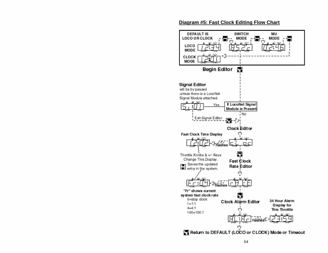
64
Diagram #5: Fast Clock Editing Flow Chart
65
19.0 DT100IR Fast Clock Many operators use a fast clock during operating sessions to simulate prototypical operations. Traditionally, this clock is on the wall and is set up to run at a faster than normal rate. The DT100IR has its own networked fast clock on all the DT100IR's in your LocoNet system. You can use this feature with both DB150 and DCS100 command stations (Chief Set) and DT200 command stations (Big Boy Sets). The Fast clock display is a 4 digit 24 Hour format clock. You can tell when your DT100IR is displaying the fast clock when you see the DT100IR's colon blinking. You can set up your DT100IR so that its default display is either the fast clock display or the LOCO mode display. When there is no activity on your DT100IR for more than about 6 seconds, the DT100IR will revert to the default display that you set up in the DT100IR. When you press any key or turn either throttle knob, the default display will change to reflect the current throttle activity. Your DT100IR was shipped to you with LOCO mode as the default display. See section 17.0 for information about making the fast clock your default display and follow the instructions in this section for setting your clock. If you have more than one DT100 series throttles on a Big Boy set, the DT100IR's will automatically synchronize their Fast clocks, even though the Big Boy's DT200 command station was not originally set up with a Fast clock. This is an example of the upgradeability benefits that a true Peer-to-Peer network architecture offer. With LocoNet you have the ability to simply add or "layer" new functional features onto your existing LocoNet system with no impact on existing hardware.
Any DT100 series throttle you plug in to your LocoNet system will update its fast clock time and rate to be synchronized to the rest of the system a couple of seconds after it is connected after being "idLE". Each DT100 can be set up with its own alarm. When the current fast clock time matches the private alarm time set in any DT100, then that DT100 only will beep and flash up the message "ALAr" to indicate that the alarm time has elapsed. The alarm time is of the same 24 Hr format as the fast clock. The fast clock rate for the Fast clock is user selectable from 1:1 to 100:1 in steps of 1, and the range values of 4:1 to 8:1 are often used. Freezing the Fast Clock Setting the clock rate to 00 will STOP or freeze the fast clock in the whole system at the currently displayed time. The time will re-start when a new non-zero rate value is selected.
66
The current fast clock time, fast clock rate and the DT100IR alarm time can be changed by using the Edit mode. Refer to Diagram 5 for a flow chart of the fast clock editing key strokes. To Edit Fast Clock Time, Rate & Alarm time. Note: Fast Clock cannot be edited while "Untethered" 1) From LOCO mode, press the key to change to SWITCH mode. 2) Press the key to change from SWITCH mode and enter EDITOR modes.
If you have routes enabled in the system, you will enter the Route Editor and the first display you will see is "rt:01". If you do not have routes enabled, you will by pass this step and go straight into the Clock Editor.
3) If routes are enabled you will need to press the key again to change from the Route Edit mode to the Fast Clock Edit mode. The display will flash "cLoc" to show it has entered the clock editor.
3a) To set the clock, use the left throttle knob to change the hours and the right throttle knobs to change minutes.
3b) When you have a Fast clock time that you want in your display, press the to "set" it in the whole system. If you do not press this key then the
system Fast clock will not be changed, and this DT100IR will re-synchronize to the system again.
3c) After modifying and setting the fast clock time, or not changing it, you can advance to the fast clock rate editor by pressing the key again. If you perform no activity for the inactive time-out (approx. 6 seconds) then the DT100IR will return back to LOCO mode.
Rate Editor: 4) Once you enter the Rate Editor the display will flash up "rAtE" on the first
screen and then will flash a second screen showing "Fr:xx" where xx is the Fast rate.
4a) You can use either knob or +/- keys to modify the Fast Clock Rate you want for the whole system.
4b) This Rate will only be updated in the system if you press the key.
Alarm Editor: 5) When you are finished with the fast clock time and rate editors, press the
key to advance to the private Alarm setting for this particular DT100IR. The DT100IR will flash up "ALAr" to indicate it is in Alarm Edit mode.
5a) You can use the knobs to modify the Hours and minutes of the 24 Hr format Alarm time.
5b) There is no need to press any key to "set" this Alarm time since it is private to this DT100IR. The value on the display is always the current Alarm time.
6) Press the key again to exit Edit modes and return to LOCO mode. You can also allow the DT100IR to time-out back to LOCO mode.
67
If you "miss" an edit value, or the DT100IR times out due to inactivity, simply restart the Edit mode and return to the Editor you wish to use.
Attached PC's and Clock repeater modules may also access, display and modify
the System Fast Clock and rate in the same ways DT100IR's can.
20.0 DB150 Option Switch Setup The DB150 has many customizable system operation options that you can set to customize your operation. The DB150's power up defaults are fine for most applications and the DB150 will run "out of the box." The factory default setting for all DB150 option switches is "t" or thrown except for 5, 17, 25, 33 and 34 which are closed.. Changing DB150 Option Switches
1. Move the Left toggle switch on the front of the DB150 into the "OP"
position. The LocoNet Rail Sync will go inactive & all other boosters, including the one that is built into the DB150 will shut down.
2. Disconnect LocoNet from the DB150 you are configuring. 3. Connect a DT100 or DT200 throttle directly to either DB150 LocoNet port A
or B.
4. Press the key on the Throttle to enter "Switch" control mode. Since the DB150 is now in "OP" or Option Switch setup mode, switch commands from a DT100 or DT200 throttle will now display & control Option switch settings & NOT turnouts on the layout!
5. You can now browse the option settings that correspond to the following table. The option switch number will appear in the left side of the display and the right side of the display will show either "c" or "t" to indicate the current state of the option switch.
6. To change the current state of any option switch press either the or key to change the option switch setting.
See * below for special instructions when using switches #36-#39. 7. After setting the "OP" switches, plug LocoNet back into Port A or B and
move the mode switch to "RUN" .
Do not adjust any "reserved" option switches since this may give unpredictable operations. Any switches not listed in the table below should be considered "reserved".
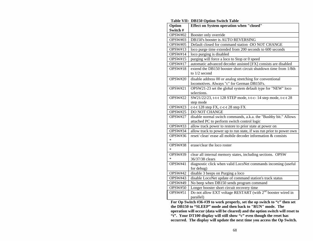
68
Table VII: DB150 Option Switch Table
Option Switch #
Effect on System operation when "closed"
OPSW#02 Booster only override OPSW#03 DB150's booster is AUTO REVERSING OPSW#05 Default closed for command station -DO NOT CHANGE OPSW#13 loco purge time extended from 200 seconds to 600 seconds OPSW#14 loco purging is disabled OPSW#15 purging will force a loco to Stop or 0 speed OPSW#17 automatic advanced decoder assisted [FX] consists are disabled OPSW#18 extend the DB150 booster short circuit shutdown time from 1/8th
to 1/2 second
OPSW#20 disable address 00 or analog stretching for conventional locomotives. Always "c" for German DB150's.
OPSW#21 OPSW21-23 set the global system default type for "NEW" loco selections.
OPSW#22 SW21/22/23, t-t-t 128 STEP mode, t-t-c- 14 step mode, t-c-t 28 step mode
OPSW#23 c-t-t 128 step FX, c-c-t 28 step FX OPSW#25 DO NOT CHANGE OPSW#27 disable normal switch commands, a.k.a. the "Bushby bit." Allows
attached PC to perform switch control logic OPSW#33 allow track power to restore to prior state at power on OPSW#34 allow track to power up to run state, if was run prior to power own OPSW#36*
reset/ clear/ erase all mobile decoder information & consists
OPSW#38*
erase/clear the loco roster
OPSW#39*
clear all internal memory states, including sections. OPSW 36/37/38 clears
OPSW#41 diagnostic click when valid LocoNet commands incoming (useful for debug)
OPSW#42 disable 3 beeps on Purging a loco OPSW#43 disable LocoNet update of command station's track status OPSW#49 No beep when DB150 sends program command OPSW#50 Longer booster short circuit recovery time OPSW#51 Do not allow EXT voltage RESTART (with 2nd booster wired in
parallel) For Op Switch #36-#39 to work properly, set the op switch to “c” then set the DB150 to “SLEEP” mode and then back to "RUN" mode. The operation will occur (data will be cleared) and the option switch will reset to “t”. Your DT100 display will still show “c” even though the reset has occurred. The display will update the next time you access the Op Switch.
69
21.0 Troubleshooting
21.1 Clean Track The majority of intermittent operation faults can be traced to bad connections and poor or noisy wheel pickups on locomotives. Check track cleanliness and quality of wheel pickups. The DCC digital packet communication strategy performs exceptionally well in a less than perfect environment, and will often mask bad connections until they are really impossible to work with!
21.2 The Quarter Trick If your track does not have adequate power supply to the locomotives, then the DCC signal won't get through either. Take a quarter or screwdriver blade and go around your layout creating electrical shorts every 10 feet. Your DB150 should beep and shutdown when the short is present. When the short is removed, the booster should return to normal operation. If this does not happen, then you need to add more feeders.
21.3 The LT1 tester Check your LocoNet cables with the LT1 tester to be sure you don't have any bad cables.
21.4 Decoder Won’t Respond Is the loco on powered track? If the throttle direction indicators on the throttle are orange press RUN/STOP and the + UP ARROW key to turn on track power. Can you select the loco on your throttle? If not, is the loco in use by another throttle or is it part of a consist (do you see a cn in the display when you try to select it)? Do the settings in CV29, the configuration register, match the command station output? If your decoder is a 14 step decoder running on an Empire Builder, status editing will be needed. Have you reset any CVs since the last time you ran the loco? If so, go back and change them to their default values and then try to run the loco. It is possible to set acceleration so high that it will take 10 minutes for the loco to start moving. Does your throttle say 'FF'? This means that the system's capacity to handle operating locos is full. The Empire Builder can run up to 22 addresses at the same time. If you have the FF message, be sure that all locos that are not running are de-selected from throttles. Was the loco running just before it stopped? If the decoder is very warm it may be in thermal shutdown. Let it cool off and see if it starts again. Also check for localized track problems. Are there burn marks on the decoder? You'll need to send it in for repair! If all else fails, reprogram the decoder address and reset CV's to default values.
70
21.5 Emergency Stop If the layout starts to "get away" on you, either PRESS "RUN/STOP" or, turn the track power to "SLEEP" on the DB150. Either way will give you a chance to regain your composure, and you will be able to rejoin the contest.
21.6 Mechanical Drive Train Problems Pay attention to the mechanical drive train and free movement of the locomotive wheel sets. This is especially important with inexpensive locomotives. Using Digitrax decoders with appropriate programming settings, you can achieve surprisingly good quality motion, if you carefully adjust the mechanisms for smooth running.
21.7 "Strange" Locomotive Lights If you can't control the operation of the lights in your locomotive with the DT100IR (in default 128, or 28 speed step mode), be sure that the decoder is programmed in advanced 28 speed step mode. Do this by programming Configuration Variable 29 with a value of "06" (the code for advanced mode per Table IV.) Refer to section 8.5 for complete programming instructions. Your Digitrax decoder has been shipped programmed to 128 speed step mode. You may have changed your decoder's programming when performing the decoder test procedure. In any case, if you are not able to turn the locomotives lights on and off, you will need to change CV 29 to "06" to have proper light operation when using the DT100IR in its optimum 128 speed step mode.
71
22.0 Glossary 128 Speed Step Mode: the motor voltage/speed curve of the DCC loco from stop to full speed has 128 discrete speed steps. This means that you have 128 discrete speed steps at your disposal for excellent speed control, especially at very low speeds. 128 speed step operation will give a significant improvement in speed control over 14 or 28 step operation. 128 speed step operation is only offered in advanced and professional level DCC systems. AC or Alternating Current: An expression used to describe an electrical wave form that cycles or alternates above and below 0 volts. In the U.S., household electricity is 60 cycle, alternating 60 times a second, 110-120 volts. Acceleration: The rate at which the decoder increases from one speed step to the next in response to a new increase speed command. Use CV 03 to set this value for each decoder. This feature is used to simulate train weight and to cause your model to respond more prototypically when you increase the throttle. Address, Decoder: a number assigned by the user to a particular mobile or stationary decoder. The DCC system uses the decoder address to send commands to the appropriate loco or accessory. Address Range: each system has a certain number of addresses that it can handle. Basic DCC systems usually handle between 6 and 16 addresses. Advanced systems usually handle between 99 & over 9000 addresses and Professional systems almost always go to 9000 or more addresses. Advanced (EPF) Consisting Method: Storage of the consist information in each decoder. The locos can be added to and deleted from the consist in any orientation. This method requires that all locomotives in the consist be equipped with decoders that support this feature(EPF decoders). This method allows you to set up a consist that will be "transportable" from one DCC layout to another but you must be sure to always put the locos back on the track in the same order and orientation you programmed them for or you can get some unexpected results. Advanced Mode (28 Speed Step Mode): the motor voltage/speed curve of the DCC loco from stop to full speed has 28 discrete speed steps. This means that speed control will be limited to 28 steps. 28 speed step mode gives fine speed control. Increasing to 128 speed step operation will give a significant improvement in speed control, especially at very slow speeds needed for prototypical switching operations. Advanced mode is offered in most command stations because there are many decoders on the market that are not capable of 128 step mode operation. Aliased 4 Digit Addressing: Lets you run 2 digit address decoders with 4 digit addresses by selecting them from the system Alias Roster. This feature gives you the ability to operate all DCC equipped decoders with 4 digit addresses. This is a function of the command station, not of the decoders. Analog Loco: A locomotive operating on a DCC layout without a DCC decoder installed. Also called a Conventional Loco. Analog Mode Conversion: When a DCC decoder does not see DCC packets on the layout it changes automatically to DC operation. Digitrax decoders support analog mode conversion but not all DCC systems do. Analog conversion can be disabled by programming CV29. Autoreversing: a feature of some DCC boosters which allows a train to enter and exit reversing sections automatically without the need for the operator to throw a switch to match track polarities on either side of the reversing section. Ballast Lamp: A high current, low voltage lamp used to protect against unwanted voltage transits. In normal model railroad applications a 12 volt automobile brake lamp wired in series is used. For
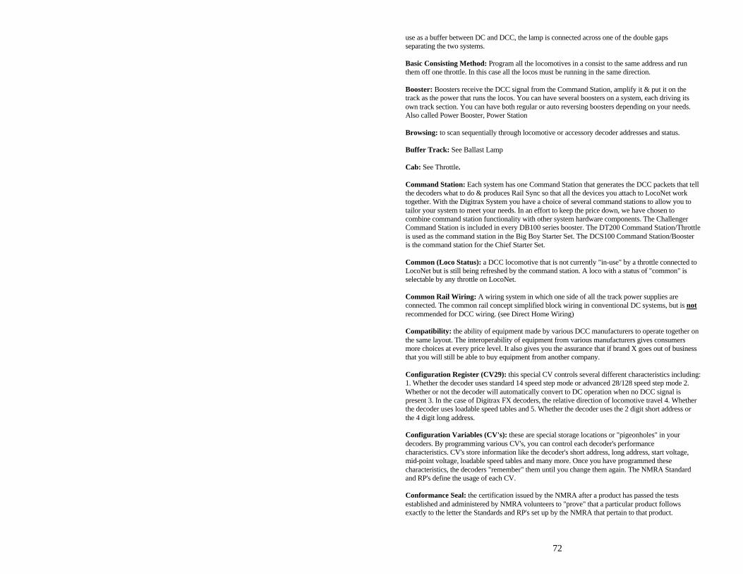
72
use as a buffer between DC and DCC, the lamp is connected across one of the double gaps separating the two systems. Basic Consisting Method: Program all the locomotives in a consist to the same address and run them off one throttle. In this case all the locos must be running in the same direction. Booster: Boosters receive the DCC signal from the Command Station, amplify it & put it on the track as the power that runs the locos. You can have several boosters on a system, each driving its own track section. You can have both regular or auto reversing boosters depending on your needs. Also called Power Booster, Power Station Browsing: to scan sequentially through locomotive or accessory decoder addresses and status. Buffer Track: See Ballast Lamp Cab: See Throttle. Command Station: Each system has one Command Station that generates the DCC packets that tell the decoders what to do & produces Rail Sync so that all the devices you attach to LocoNet work together. With the Digitrax System you have a choice of several command stations to allow you to tailor your system to meet your needs. In an effort to keep the price down, we have chosen to combine command station functionality with other system hardware components. The Challenger Command Station is included in every DB100 series booster. The DT200 Command Station/Throttle is used as the command station in the Big Boy Starter Set. The DCS100 Command Station/Booster is the command station for the Chief Starter Set. Common (Loco Status): a DCC locomotive that is not currently "in-use" by a throttle connected to LocoNet but is still being refreshed by the command station. A loco with a status of "common" is selectable by any throttle on LocoNet. Common Rail Wiring: A wiring system in which one side of all the track power supplies are connected. The common rail concept simplified block wiring in conventional DC systems, but is not recommended for DCC wiring. (see Direct Home Wiring) Compatibility: the ability of equipment made by various DCC manufacturers to operate together on the same layout. The interoperability of equipment from various manufacturers gives consumers more choices at every price level. It also gives you the assurance that if brand X goes out of business that you will still be able to buy equipment from another company. Configuration Register (CV29): this special CV controls several different characteristics including: 1. Whether the decoder uses standard 14 speed step mode or advanced 28/128 speed step mode 2. Whether or not the decoder will automatically convert to DC operation when no DCC signal is present 3. In the case of Digitrax FX decoders, the relative direction of locomotive travel 4. Whether the decoder uses loadable speed tables and 5. Whether the decoder uses the 2 digit short address or the 4 digit long address. Configuration Variables (CV's): these are special storage locations or "pigeonholes" in your decoders. By programming various CV's, you can control each decoder's performance characteristics. CV's store information like the decoder's short address, long address, start voltage, mid-point voltage, loadable speed tables and many more. Once you have programmed these characteristics, the decoders "remember" them until you change them again. The NMRA Standard and RP's define the usage of each CV. Conformance Seal: the certification issued by the NMRA after a product has passed the tests established and administered by NMRA volunteers to "prove" that a particular product follows exactly to the letter the Standards and RP's set up by the NMRA that pertain to that product.
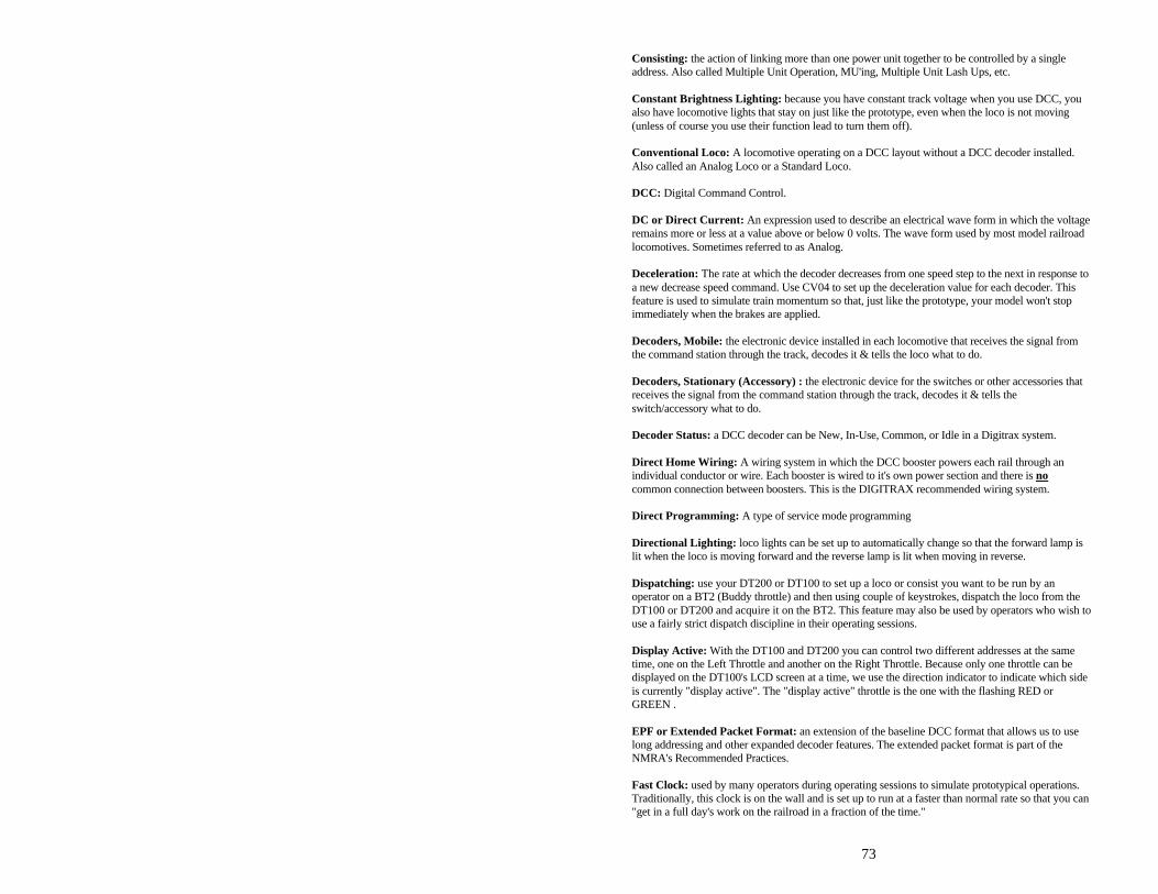
73
Consisting: the action of linking more than one power unit together to be controlled by a single address. Also called Multiple Unit Operation, MU'ing, Multiple Unit Lash Ups, etc. Constant Brightness Lighting: because you have constant track voltage when you use DCC, you also have locomotive lights that stay on just like the prototype, even when the loco is not moving (unless of course you use their function lead to turn them off). Conventional Loco: A locomotive operating on a DCC layout without a DCC decoder installed. Also called an Analog Loco or a Standard Loco. DCC: Digital Command Control. DC or Direct Current: An expression used to describe an electrical wave form in which the voltage remains more or less at a value above or below 0 volts. The wave form used by most model railroad locomotives. Sometimes referred to as Analog. Deceleration: The rate at which the decoder decreases from one speed step to the next in response to a new decrease speed command. Use CV04 to set up the deceleration value for each decoder. This feature is used to simulate train momentum so that, just like the prototype, your model won't stop immediately when the brakes are applied. Decoders, Mobile: the electronic device installed in each locomotive that receives the signal from the command station through the track, decodes it & tells the loco what to do. Decoders, Stationary (Accessory) : the electronic device for the switches or other accessories that receives the signal from the command station through the track, decodes it & tells the switch/accessory what to do. Decoder Status: a DCC decoder can be New, In-Use, Common, or Idle in a Digitrax system. Direct Home Wiring: A wiring system in which the DCC booster powers each rail through an individual conductor or wire. Each booster is wired to it's own power section and there is no common connection between boosters. This is the DIGITRAX recommended wiring system. Direct Programming: A type of service mode programming Directional Lighting: loco lights can be set up to automatically change so that the forward lamp is lit when the loco is moving forward and the reverse lamp is lit when moving in reverse. Dispatching: use your DT200 or DT100 to set up a loco or consist you want to be run by an operator on a BT2 (Buddy throttle) and then using couple of keystrokes, dispatch the loco from the DT100 or DT200 and acquire it on the BT2. This feature may also be used by operators who wish to use a fairly strict dispatch discipline in their operating sessions. Display Active: With the DT100 and DT200 you can control two different addresses at the same time, one on the Left Throttle and another on the Right Throttle. Because only one throttle can be displayed on the DT100's LCD screen at a time, we use the direction indicator to indicate which side is currently "display active". The "display active" throttle is the one with the flashing RED or GREEN . EPF or Extended Packet Format: an extension of the baseline DCC format that allows us to use long addressing and other expanded decoder features. The extended packet format is part of the NMRA's Recommended Practices. Fast Clock: used by many operators during operating sessions to simulate prototypical operations. Traditionally, this clock is on the wall and is set up to run at a faster than normal rate so that you can "get in a full day's work on the railroad in a fraction of the time."
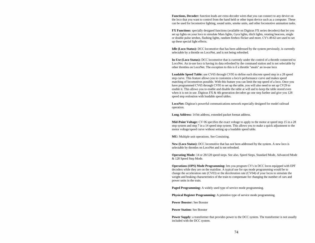
74
Functions, Decoder: function leads are extra decoder wires that you can connect to any device on the loco that you want to control from the hand held or other input device such as a computer. These can be used for locomotive lighting, sound units, smoke units, and other locomotive animation tasks. FX Functions: specially designed functions (available on Digitrax FX series decoders) that let you set up lights on your loco to simulate Mars lights, Gyra lights, ditch lights, rotating beacons, single or double pulse strobes, flashing lights, random firebox flicker and more. CV's 49-63 are used to set up these special light effects. Idle (Loco Status): DCC locomotive that has been addressed by the system previously, is currently selectable by a throttle on LocoNet, and is not being refreshed. In-Use (Loco Status): DCC locomotive that is currently under the control of a throttle connected to LocoNet. An in-use loco is having its data refreshed by the command station and is not selectable by other throttles on LocoNet. The exception to this is if a throttle "steals" an in-use loco Loadable Speed Table: use CV65 through CV95 to define each discrete speed step in a 28 speed step curve. This feature allows you to customize a loco's performance curve and makes speed matching of locomotives possible. With this feature you can limit the top speed of a loco. Once you have programmed CV65 through CV95 to set up the table, you will also need to set up CV29 to enable it. This allows you to enable and disable the table at will and to keep the table stored even when it is not in use. Digitrax FX & 4th generation decoders go one step further and give you 128 speed step resloution with loadable speed tables. LocoNet: Digitrax's powerful communications network especially designed for model railroad operation. Long Address: 14 bit address, extended packet format address. Mid-Point Voltage: CV 06 specifies the exact voltage to apply to the motor at speed step 15 in a 28 step system and step 7 in a 14 speed step system. This allows you to make a quick adjustment to the motor voltage/speed curve without setting up a loadable speed table. MU: Multiple unit operations. See Consisting. New (Loco Status): DCC locomotive that has not been addressed by the system. A new loco is selectable by throttles on LocoNet and is not refreshed. Operating Mode: 14 or 28/128 speed steps. See also, Speed Steps, Standard Mode, Advanced Mode & 128 Speed Step Mode. Operations (OPS) Mode Programming: lets you program CV's in DCC locos equipped with EPF decoders while they are on the mainline. A typical use for ops mode programming would be to change the acceleration rate (CV03) or the deceleration rate (CV04) of your locos to simulate the weight and braking characteristics of the train to compensate for changing the number of cars and power units in the train. Paged Programming: A widely used type of service mode programming. Physical Register Programming: A primitive type of service mode programming. Power Booster: See Booster Power Station: See Booster Power Supply: a transformer that provides power to the DCC system. The transformer is not usually included with the DCC system.
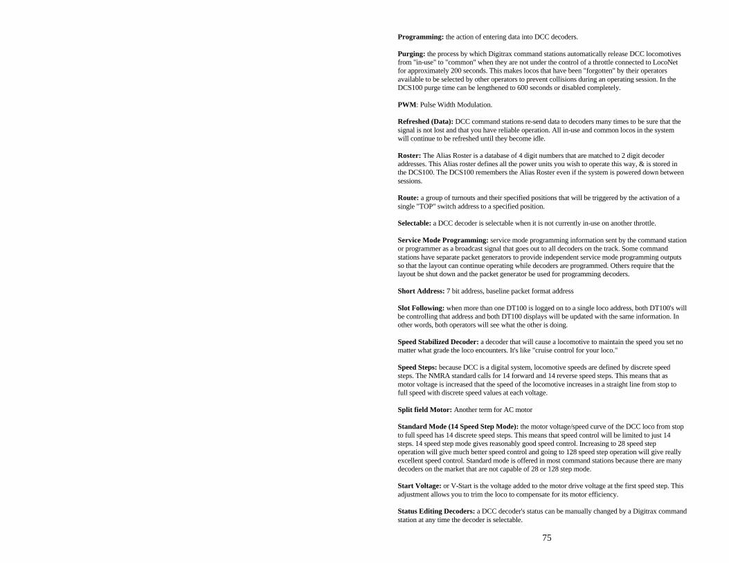
75
Programming: the action of entering data into DCC decoders. Purging: the process by which Digitrax command stations automatically release DCC locomotives from "in-use" to "common" when they are not under the control of a throttle connected to LocoNet for approximately 200 seconds. This makes locos that have been "forgotten" by their operators available to be selected by other operators to prevent collisions during an operating session. In the DCS100 purge time can be lengthened to 600 seconds or disabled completely. PWM: Pulse Width Modulation. Refreshed (Data): DCC command stations re-send data to decoders many times to be sure that the signal is not lost and that you have reliable operation. All in-use and common locos in the system will continue to be refreshed until they become idle. Roster: The Alias Roster is a database of 4 digit numbers that are matched to 2 digit decoder addresses. This Alias roster defines all the power units you wish to operate this way, & is stored in the DCS100. The DCS100 remembers the Alias Roster even if the system is powered down between sessions. Route: a group of turnouts and their specified positions that will be triggered by the activation of a single "TOP" switch address to a specified position. Selectable: a DCC decoder is selectable when it is not currently in-use on another throttle. Service Mode Programming: service mode programming information sent by the command station or programmer as a broadcast signal that goes out to all decoders on the track. Some command stations have separate packet generators to provide independent service mode programming outputs so that the layout can continue operating while decoders are programmed. Others require that the layout be shut down and the packet generator be used for programming decoders. Short Address: 7 bit address, baseline packet format address Slot Following: when more than one DT100 is logged on to a single loco address, both DT100's will be controlling that address and both DT100 displays will be updated with the same information. In other words, both operators will see what the other is doing. Speed Stabilized Decoder: a decoder that will cause a locomotive to maintain the speed you set no matter what grade the loco encounters. It's like "cruise control for your loco." Speed Steps: because DCC is a digital system, locomotive speeds are defined by discrete speed steps. The NMRA standard calls for 14 forward and 14 reverse speed steps. This means that as motor voltage is increased that the speed of the locomotive increases in a straight line from stop to full speed with discrete speed values at each voltage. Split field Motor: Another term for AC motor Standard Mode (14 Speed Step Mode): the motor voltage/speed curve of the DCC loco from stop to full speed has 14 discrete speed steps. This means that speed control will be limited to just 14 steps. 14 speed step mode gives reasonably good speed control. Increasing to 28 speed step operation will give much better speed control and going to 128 speed step operation will give really excellent speed control. Standard mode is offered in most command stations because there are many decoders on the market that are not capable of 28 or 128 step mode. Start Voltage: or V-Start is the voltage added to the motor drive voltage at the first speed step. This adjustment allows you to trim the loco to compensate for its motor efficiency. Status Editing Decoders: a DCC decoder's status can be manually changed by a Digitrax command station at any time the decoder is selectable.

76
Stealing a Loco: this procedure allows a UT2 user on a Genesis Set or a DT100 user on a Chief Set or Empire Builder to override the in-use interlock and force the throttle to log on to an in-use loco. This can result in having two throttles logged on to and controlling one address. See also Slot Following. Throttles: Throttles are input devices that tell the Command Station what you want the decoders to do. You can have many throttles on your system. The number is determined by the capabilities of the Command Station you are using. You can also use a computer to create "soft" throttles. Sometimes DCC throttles are also called "Cabs." TOP Locomotive: We call the "key" locomotive that other locomotives are consisted TO, the TOP locomotive because it does not need to be in any particular physical order in the consist. The TOP locomotive address controls the speed & direction of all locomotives consisted to it by the MU function. The "TOP" locomotive does not have to exist. You can use a 2 digit train number, for example , as your "TOP" locomotive. Universal Consisting method is handled by the command station and allows you to consist locos with any DCC decoder as well as an analog loco. The locos can be added to and deleted from the consist in any orientation head to head or tail to tail. Zero-Stretching incorporates a time period between packets to give you an effective DC offset between the two rails. This allows you to control a DC locomotive along with the DCC locomotives on a DCC system.
23.0 FCC Information Radio or TV Interference: (this information is MANDATED by the FCC) This equipment has been tested and found to comply with the limits for a Class B digital device, pursuant to part 15 of the FCC rules. These limits are designed to provide reasonable protection against harmful interference in a residential environment. This equipment generates, uses and can radiate radio frequency energy and, if not installed and used in accordance with the instruction manual, may cause harmful interference to radio communications. However, there is no guarantee that interference will not occur in a particular installation. If this equipment does cause harmful interference to radio or television reception, which can be determined by turning the equipment off and on, the user is encouraged to try to correct the interference by one or more of the following measures: -Reorient or relocate the receiving antenna. -Increase the separation between the equipment and the receiver. -Connect the equipment into an outlet on a circuit different form that to which the receiver is connected. -Consult the dealer or an experienced radio/TV technician for help. Note that any modifications to the equipment not expressly approved by Digitrax voids the user's authority to operate under and be in compliance with CFR 47 rules, as administered by the Federal Communication Commission. Digitrax believes any conscientiously installed equipment following guidelines in this manual would be unlikely to experience RFI problems. For Canadian Users: "This digital apparatus does not exceed the Class B limits for Radio noise emission from digital apparatus set out in the Radio Interference Regulation or the Canadian Department of Communications." Le present appariel numerique n emet pas de bruits radio-electriques depassant les limites applicables aux appareils numeriques de la classe B prescrites dans le Reglement sur le brouillage radioelectrique edicte par le ministere des Communications du Canada.
77
24.0 Warranty and Repair Information: Digitrax gives a one year guarantee on DT100IR and DB150. These units are not user serviceable (opening the case voids your warranty). If a defect occurs, return the unit to us for service. We will repair or replace these units at our discretion at no charge to you for one year from purchase date. This warranty excludes damage due to abuse, such as failure to properly protect against input over current with a fuse or circuit breaker or applying excessive input voltage to the unit. We will make any repair needed because of physical damage or electrical abuse at fair and reasonable rates. Decoders Digitrax carefully tests every decoder we ship to be sure that you receive reliable products. Because we want you to be comfortable installing your own decoders, we outline a decoder test procedure that you can perform so that you can be sure your decoder works before you begin installing it in your locomotive. If, within 60 days of purchase, your decoder fails to pass the decoder test procedure outlined in the instructions, we will replace it free of charge to you. Because we can't control the actual decoder installation we can't cover your decoder once you have tested it and started the installation. In the event that you somehow manage to "blow-up" one of these little guys, we will repair or replace it for a nominal fee (call for the current amount) if you return the decoder to us. Do not remove the shrink-wrap protective sleeves from Digitrax decoders or open the Command Stations or other products. None of the units have user serviceable parts, and opening them will void ALL warranty protection. If you are returning a decoder that failed the test procedure, all wires must be their original lengths. Do not cut any wires or install any units until you are sure they have passed the Decoder Test Procedure detailed in the Decoder Manual. Please don't return anything to Digitrax without calling and getting return instructions. In order to make sure we give you the best service possible, please call (770) 441-7992 to let us know before you send anything to us for service or as a return. All warranties on Digitrax products are limited to refund of purchase price or repair or replacement of Digitrax products at the sole discretion of Digitrax. In the event that Digitrax products are not installed or used in accordance with the manufacturer's specifications, any and all warranties either expressed or implied are void. Except to the extent expressly stated in this section, there are no warranties, express or implied, including but not limited to any warranties of merchantability or fitness for a particular purpose.
Digitrax, Inc. reserves the right to make changes in design and specifications, and/or to make additions or improvements in its products without imposing any obligations upon itself to install these changes, additions or improvements on products previously manufactured.
78
INDEX 2 digit short address ...................32 2 digit short address .. 8, 26, 27, 30,
31, 32, 33, 34, 39, 44, 45, 57, 62, 63, 72
4 digit long address ........ 26, 32, 34 Adding a Locomotive To A Consist
..............................................44 Analog Loco.................... 7, 71, 73 analog locomotive......................19 Analog Mode ............................71 analog operations.......................68 Arnold .......................................42 AUDIBLE SOUNDS.................24 automatic reversing....................68 ballistic tracking ............ 26, 29, 47 Battery “Fuel Gauge”.................51 beeps & clicks ............... 37, 47, 68 Breaking A Loco Out Of A Consist
..............................................45 clean track .................................69 common locomotives..................40 CONFIG A.................... 16, 18, 23 CONFIG B ................................23 Configuration Register.. 55, 59, 60,
72 Consisting, Basic .......................43 Consisting, UniVersal ................43 CV's (configuration variables)...53,
54, 59, 62 data refresh ................................40 DB150...5, 6, 8, 10, 11, 14, 16, 17,
18, 19, 21, 22, 23, 29, 32, 35, 37, 43, 53, 54, 65, 67, 68, 70, 77
DCC.................................... 14, 15 DCS100 Option Switches .........67 decoder programming ................17 decoder status codes............. 40, 41 direction control................... 28, 31
direction indicators .................... 26 dirty track.................................. 40 dispatching .......................... 28, 39 DT100 Configuration Options.... 46 emergency stop.......................... 70 fast clock ............................ 47, 65 fast clock alarm........................ 66 fast clock rate ...................... 65, 66 fault........................................... 23 FAULT CODES........................ 22 FCC information........................ 76 FF message in DT100 display .... 32 Four Digit Long Address
Programming......................... 54 function control.................. 28, 38 function control, consists ........... 39 Ground Terminal ....................... 22 grounding .................................. 22 Infrared Override....................... 52 in-use locomotives......... 35, 37, 40 Keyboard Lock Out ................... 52 Lenz .................................... 42, 59 lights, problems with ................. 70 loadable speed table....... 57, 58, 59 locomotive wheel pickups.......... 69 LocoNet .............................. 20, 23 LocoNet ID change.................... 50 Making track & booster
connections.............................. 5 Marklin ..................................... 42 mechanical problems with locos. 70 Mode Switch ............................. 24 MODE switch.............................. 5 MRC ......................................... 42 MU operations/consisting ... 39, 43,
44, 46, 68
1
Nested Consisting ......................46 Nested Consisting.....................45 Operations mode........................62 over temp ..................................23 POWER IN............................ 5, 21 Power Saver Mode......................... programming ................. 54, 56, 58 programming mode.............. 26, 29 Programming Mode ............. 29, 51 programming track.....................17 purge ............................. 35, 37, 68 resume.......................................10 reversing sections ......................17 Run/Stop, Global ................. 27, 47 Run/Stop, Local ................. 27, 47 running trains, LOCO Mode.......29 scale voltage switch ...................24 sectioning the layout ..................15
Select/Set ............................ 27, 30 Selecting an address................... 32 short circuit shutdown................ 68 Sleep ................................... 10, 24 speed control ............................ 31 speed matching.................... 46, 57 stealing...................................... 35 stop ........................................... 29 straight line (normal) tracking .... 26 switch control ................ 28, 42, 68 switch position............... 28, 42, 43 Tetherless” Operation ................ 50
Infrared.................................. 50 TRACK STATUS ............. 5, 8, 22 track wiring ......................... 14, 19 training mode ............................ 37 Transformers ............................. 21 troubleshooting.......................... 69 Warranty and Repair Information
.............................................. 77 wiring, LocoNet color code........ 23