emission factor documentation for ap-42 … emission factor documentation for ap-42 section 11.5...
TRANSCRIPT
1
Emission Factor Documentation for AP-42Section 11.5
Refractory Manufacturing
Final Report
For U. S. Environmental Protection AgencyOffice of Air Quality Planning and Standards
Emission Inventory Branch
EPA Contract 68-D2-0159Work Assignment No. I-01
MRI Project No. 4601-01
May 20, 1994
2
Emission Factor Documentation for AP-42Section 11.5
Refractory Manufacturing
Final Report
For U. S. Environmental Protection AgencyOffice of Air Quality Planning and Standards
Emission Inventory BranchResearch Triangle Park, NC 27711
Attn: Mr. Ron Myers (MD-14)Emission Factor and Methodology
EPA Contract 68-D2-0159Work Assignment No. I-01
MRI Project No. 4601-01
May 20, 1994
iii
PREFACE
This report was prepared by Midwest Research Institute (MRI) for the Office of Air Quality
Planning and Standards (OAQPS), U. S. Environmental Protection Agency (EPA), under Contract
No. 68-D2-0159, Work Assignment No. I-01. Mr. Ron Myers was the requester of the work. The
report was prepared by Richard Marinshaw and Brian Strong.
Approved for:
MIDWEST RESEARCH INSTITUTE
Roy NeulichtProgram ManagerEnvironmental Engineering Department
Jeff ShularDirector, Environmental Engineering Department
May 20, 1994

iv
v
CONTENTS
List of Figures . . . . . . . . . . . . . . . . . . . . . . . . . . . . . . . . . . . . . . . . . . . . . . . . . . . . . . . . . . . . viList of Tables . . . . . . . . . . . . . . . . . . . . . . . . . . . . . . . . . . . . . . . . . . . . . . . . . . . . . . . . . . . . . vi
1. INTRODUCTION . . . . . . . . . . . . . . . . . . . . . . . . . . . . . . . . . . . . . . . . . . . . . . . . . . . . . . 1
2. INDUSTRY DESCRIPTION . . . . . . . . . . . . . . . . . . . . . . . . . . . . . . . . . . . . . . . . . . . . . . 22.1 CHARACTERIZATION OF THE INDUSTRY . . . . . . . . . . . . . . . . . . . . . . . . . . . . . 22.2 PROCESS DESCRIPTION . . . . . . . . . . . . . . . . . . . . . . . . . . . . . . . . . . . . . . . . . . . . 22.3 EMISSIONS . . . . . . . . . . . . . . . . . . . . . . . . . . . . . . . . . . . . . . . . . . . . . . . . . . . . . . . 52.4 CONTROL TECHNOLOGY . . . . . . . . . . . . . . . . . . . . . . . . . . . . . . . . . . . . . . . . . . . 5
3. GENERAL DATA REVIEW AND ANALYSIS . . . . . . . . . . . . . . . . . . . . . . . . . . . . . . . . 73.1 LITERATURE SEARCH AND SCREENING . . . . . . . . . . . . . . . . . . . . . . . . . . . . . . 73.2 EMISSION DATA QUALITY RATING SYSTEM . . . . . . . . . . . . . . . . . . . . . . . . . . 83.3 EMISSION FACTOR QUALITY RATING SYSTEM . . . . . . . . . . . . . . . . . . . . . . . . 9
4. AP-42 SECTION DEVELOPMENT . . . . . . . . . . . . . . . . . . . . . . . . . . . . . . . . . . . . . . . . . 104.1 REVISIONS TO SECTION NARRATIVE . . . . . . . . . . . . . . . . . . . . . . . . . . . . . . . . 104.2 POLLUTANT EMISSION FACTOR DEVELOPMENT . . . . . . . . . . . . . . . . . . . . . . 10
4.2.1 Review of Specific Data Sets . . . . . . . . . . . . . . . . . . . . . . . . . . . . . . . . . . . . . . 104.2.2 Review of XATEF and SPECIATE Data Base Emission
Factors . . . . . . . . . . . . . . . . . . . . . . . . . . . . . . . . . . . . . . . . . . . . . . . . . . . . . . 124.2.3 Review of Test Data in AP-42 Background File . . . . . . . . . . . . . . . . . . . . . . . . 124.2.4 Results of Data Analysis . . . . . . . . . . . . . . . . . . . . . . . . . . . . . . . . . . . . . . . . . 13
5. AP-42 SECTION 11.5 . . . . . . . . . . . . . . . . . . . . . . . . . . . . . . . . . . . . . . . . . . . . . . . . . . . 32
vi
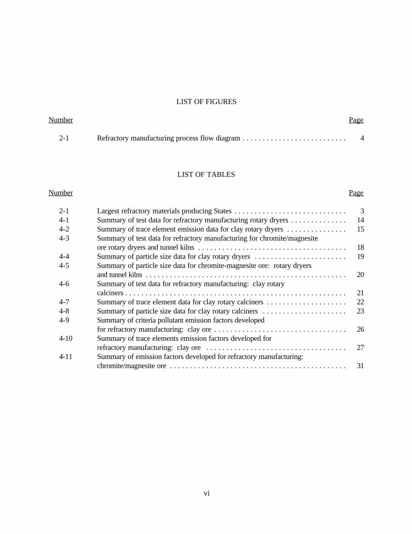
LIST OF FIGURES
Number Page
2-1 Refractory manufacturing process flow diagram . . . . . . . . . . . . . . . . . . . . . . . . . . 4
LIST OF TABLES
Number Page
2-1 Largest refractory materials producing States . . . . . . . . . . . . . . . . . . . . . . . . . . . . 34-1 Summary of test data for refractory manufacturing rotary dryers . . . . . . . . . . . . . . 144-2 Summary of trace element emission data for clay rotary dryers . . . . . . . . . . . . . . . 154-3 Summary of test data for refractory manufacturing for chromite/magnesite
ore rotary dryers and tunnel kilns . . . . . . . . . . . . . . . . . . . . . . . . . . . . . . . . . . . . . 184-4 Summary of particle size data for clay rotary dryers . . . . . . . . . . . . . . . . . . . . . . . 194-5 Summary of particle size data for chromite-magnesite ore: rotary dryers
and tunnel kilns . . . . . . . . . . . . . . . . . . . . . . . . . . . . . . . . . . . . . . . . . . . . . . . . . . 204-6 Summary of test data for refractory manufacturing: clay rotary
calciners . . . . . . . . . . . . . . . . . . . . . . . . . . . . . . . . . . . . . . . . . . . . . . . . . . . . . . . 214-7 Summary of trace element data for clay rotary calciners . . . . . . . . . . . . . . . . . . . . 224-8 Summary of particle size data for clay rotary calciners . . . . . . . . . . . . . . . . . . . . . 234-9 Summary of criteria pollutant emission factors developed
for refractory manufacturing: clay ore . . . . . . . . . . . . . . . . . . . . . . . . . . . . . . . . . 264-10 Summary of trace elements emission factors developed for
refractory manufacturing: clay ore . . . . . . . . . . . . . . . . . . . . . . . . . . . . . . . . . . . 274-11 Summary of emission factors developed for refractory manufacturing:
chromite/magnesite ore . . . . . . . . . . . . . . . . . . . . . . . . . . . . . . . . . . . . . . . . . . . . 31
1
EMISSION FACTOR DOCUMENTATION FOR AP-42 SECTION 11.5Refractory Manufacturing
1. INTRODUCTION
The document "Compilation of Air Pollutant Emissions Factors" (AP-42) has been published bythe U. S. Environmental Protection Agency (EPA) since 1972. Supplements to AP-42 have beenroutinely published to add new emission source categories and to update existing emission factors. AP-42is routinely updated by EPA to respond to new emission factor needs of EPA, State, and local air pollutioncontrol programs, and industry.
An emission factor relates the quantity (weight) of pollutants emitted to a unit of activity of thesource. The uses for the emission factors reported in AP-42 include:
1. Estimates of areawide emissions;
2. Estimates of emissions for a specific facility; and
3. Evaluation of emissions relative to ambient air quality.
The purpose of this report is to provide background information from test reports and otherinformation to support revision of the AP-42 section on refractory manufacturing.
This background report consists of five sections. Section 1 includes the introduction to the report. Section 2 gives a description of the refractory manufacturing industry. It includes a characterization ofthe industry, an overview of the different process types, a description of emissions, and a description ofthe technology used to control emissions resulting from refractory manufacturing. Section 3 is a review ofemissions data collection and analysis procedures. It describes the literature search, the screening ofemission data reports, and the quality rating system for both emission data and emission factors. Section 4details revisions to the existing AP-42 section narrative and the development of pollutant emission factors. It includes the review of specific data sets and the results of data analysis. Section 5 presents AP-42Section 11.5, Refractory Manufacturing.
2
2. INDUSTRY DESCRIPTION1
Refractories are materials that provide linings for high-temperature furnaces and other processingunits. Refractories must be able to withstand physical wear, high temperatures (above 538EC [1000EF]),and corrosion by chemical agents. There are two general classifications of refractories: clay (StandardIndustrial Classification [SIC] Code 3255) and nonclay (SIC Code 3297). The six-digit sourceclassification code (SCC) for refractory manufacturing is 3-05-005.
Clay refractories are produced from fire clay (hydrous silicates of aluminum) and alumina (57 to87.5 percent). Other clay minerals used in the production of refractories include kaolin, bentonite, ballclay, and common clay. Nonclay refractories are produced from a composition of alumina (<87.5percent), mullite, chromite, magnesite, silica, silicon carbide, zircon, and other nonclays.
Refractories are produced in two basic forms: preshaped objects and unformed compositions ingranulated or plastic forms. The preformed products are called bricks and shapes. These products areused to form the walls, arches, and floor tiles of various high-temperature process equipment. Unformedcompositions include mortars, gunning mixes, castables (refractory concretes), ramming mixes, andplastics. These products are then cured to form a monolithic, internal structure after application.
2.1 CHARACTERIZATION OF THE INDUSTRY2
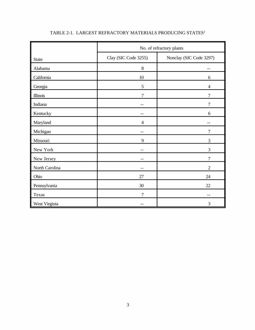
There are a total of approximately 280 refractory manufacturing plants operating in the UnitedStates. This total is divided more or less equally between clay and nonclay refractory plants. Refractorymaterials are produced in 37 States, and the leading producers are Ohio and Pennsylvania. Table 2-1
3
TABLE 2-1. LARGEST REFRACTORY MATERIALS PRODUCING STATES2
State
No. of refractory plants
Clay (SIC Code 3255) Nonclay (SIC Code 3297)
Alabama 8 --
California 10 6
Georgia 5 4
Illinois 7 7
Indiana -- 7
Kentucky -- 6
Maryland 4 --
Michigan -- 7
Missouri 9 3
New York -- 3
New Jersey -- 7
North Carolina -- 2
Ohio 27 24
Pennsylvania 30 22
Texas 7 --
West Virginia -- 3
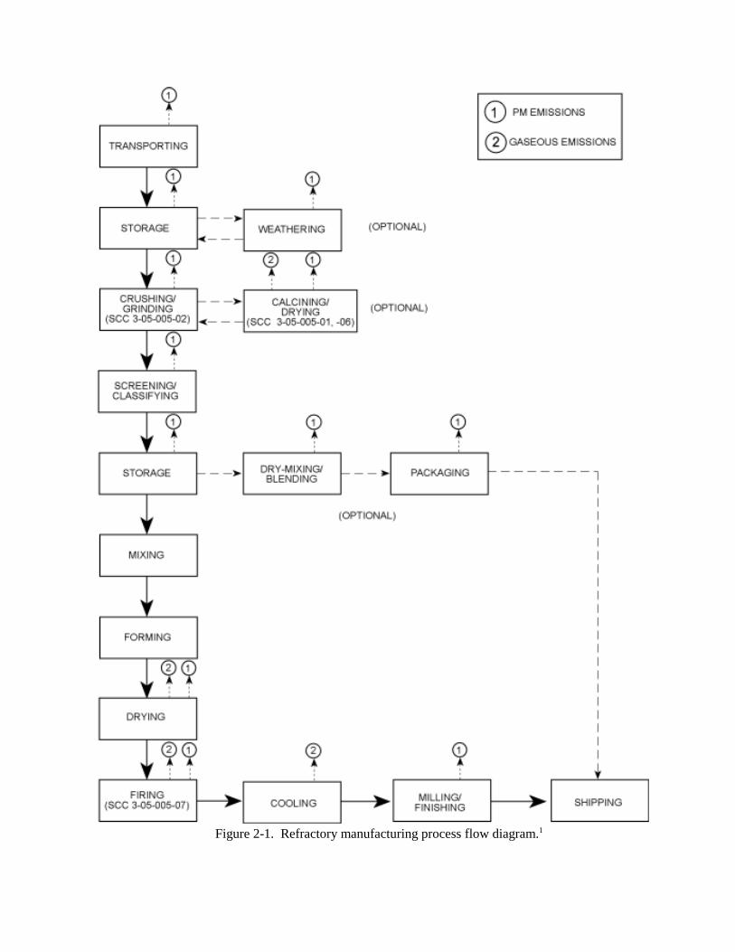
Figure 2-1. Refractory manufacturing process flow diagram.1
4
lists the number of plants by State for the largest producers of refractory materials. The largestproducers of fire clay, which is the most widely used raw material for refractory manufacturing, areMissouri, Ohio, and Alabama. Total annual shipments of refractory materials in the United States isapproximately $2 billion.
2.2 PROCESS DESCRIPTION1,3
Refractory manufacturing involves four processes: raw material processing, forming, firing, andfinal processing. Figure 2-1 illustrates the refractory manufacturing process. Raw material processingconsists of crushing and grinding raw materials, followed by size classification and calcining and dryingthe raw materials, if necessary. Some of these processes are not required for certain types of refractoryproducts. The processed raw material then may be dry-mixed with other minerals and chemicalcompounds, packaged, and shipped as product.
Forming consists of mixing the raw materials and forming them into the desired shapes. Thisprocess frequently occurs under wet or moist conditions. Firing involves heating the refractory material tohigh temperatures in a periodic (batch) or continuous tunnel kiln to form the ceramic bond that gives theproduct its refractory properties. The final processing stage involves milling, grinding, and sandblasting ofthe finished product. This step allows the product to maintain the correct shape and size after thermalexpansion has occurred. For certain products, final processing may also include impregnating the productwith tar and pitch, and final packaging.
6
Two other types of refractory processes also warrant discussion. The first is production of fusedproducts. This process involves using an electric arc furnace to melt the refractory raw materials, thenpouring the melted materials into sand molds for forming. Another type of refractory process is ceramicfiber production. In this process, calcined kaolin is melted in an electric arc furnace. The melted materialis then fiberized in a blowchamber with a centrifuge device, or the molten clay is dropped into an air jetand is immediately blown into fine strands. After the blowchamber, the ceramic fiber may then beconveyed to an oven for curing, which adds structural rigidity to the fibers. During the curing process, oilsare used to lubricate the fibers and the machinery used to handle and form the fibers. The production ofceramic fiber for refractory material is very similar to the production of mineral wool.
2.3 EMISSIONS3-8
The primary pollutant of concern that is emitted in refractory manufacturing is particulate matter(PM). Particulate matter emissions occur during the crushing, grinding, screening, calcining and drying ofthe raw materials, firing of the green refractory bricks, tar and pitch operations, and finishing of therefractories (grinding, milling, and sandblasting). The greatest emissions of PM are from the refractoryfiring kilns and electric arc furnaces.
Pollutants emitted as a result of combustion in the calcining and kilning processes include sulfuroxides (SOx), nitrogen oxides (NOx), carbon monoxide (CO), and volatile organic compounds (VOC's). Volatile organic compounds are also emitted by tar and pitch operations. The emission of SOx is afunction of the sulfur content of certain clays and the plaster added to refractory materials to induce bricksetting. Fluoride emissions occur during the kilning process and are a result of fluorides in the rawmaterials.
Chromium is used in several types of nonclay refractories, including chrome-magnesite(chromite-magnesite), magnesia-chrome, and chrome-alumina. Chromium compounds are emitted fromthe ore crushing and grinding, material drying and storage, and refractory firing and finishing processesused in producing these types of refractories. In addition, a number of elements in trace concentrations,including aluminum, beryllium, lead, mercury, manganese, nickel, titanium, vanadium, and zinc are emittedin trace amounts by drying, calcining, and firing operations of all types of refractory materials.
2.4 CONTROL TECHNOLOGY3-8
Emissions from crushing and grinding operations generally are controlled with fabric filters. Product recovery cyclones followed by wet scrubbers are used on calciners and dryers to control PMemissions from these sources.
Particulate matter emissions from kilns generally are not controlled. However, at least onerefractory manufacturer currently uses a multiple-stage scrubber to control kiln emissions. Particulatematter emissions from electric arc furnaces generally are controlled with fabric filters. Particulate matterremoval of 87 percent and fluoride removal of greater than 99 percent have been reported at one facilitythat uses an ionizing wet scrubber.
Volatile organic compounds emitted from tar and pitch operations generally are controlled byincineration, when inorganic particulates are not significant. Based on destruction of organic aerosols, acontrol efficiency in excess of 95 percent can be achieved using incinerators.
7
Emissions of PM from the ceramic fiber process also are controlled with fabric filters, and theefficiency is similar to that found in the fused cast refractory process. To control blowchamber emissions,a fabric filter is used to remove small pieces of fine threads that are formed in the fiberization stage. Theefficiency of fabric filters in similar control devices exceeds 99 percent. Small particles of ceramic fiberare broken off or separated during the handling and forming of the fiber blankets in the curing oven. Anoil is used in this process, and higher molecular weight organics are emitted. These emissions arecontrolled using a fabric filter followed by incineration. An overall efficiency in excess of 95 percent isexpected for this type of control.
REFERENCES FOR SECTION 2
1. Refractories, The Refractories Institute, Pittsburgh, PA, 1987.
2. 1987 Census of Manufactures, U.S. Department of Commerce, Washington D.C., May 1990.
3. Source Category Survey: Refractory Industry, EPA-450/3-80-006, U. S. EnvironmentalProtection Agency, Research Triangle Park, NC, March 1980.
4. Locating and Estimating Air Emissions from Sources of Chromium, EPA-450/4-84-007g, U. S.Environmental Protection Agency, Research Triangle Park, NC, 1985.
5. Calciners and Dryers Emission Test Report, North American Refractories Company, Farber,Missouri, EMB Report 84-CDR-14, U. S. Environmental Protection Agency, Research TrianglePark, NC, March 1984.
6. Emission Test Report: Plant A, Confidential Business Information Files, Document No. C-7-12,ESD Project No. 81/08, U. S. Environmental Protection Agency, Research Triangle Park, NC.
7. Calciners and Dryers Emission Test Report, A. P. Green Company, Mexico, Missouri, EMBReport 83-CDR-1, U. S. Environmental Protection Agency, Research Triangle Park, NorthCarolina, October 1983.
8. Chromium Screening Study Test Report, Harbison-Walker Refractories, Baltimore, Maryland,EMB Report 85-CHM-12, U. S. Environmental Protection Agency, Research Triangle Park, NC,June 1985.
8
3. GENERAL DATA REVIEW AND ANALYSIS
3.1 LITERATURE SEARCH AND SCREENING
Data for this investigation were obtained from a number of sources within the Office of AirQuality Planning and Standards (OAQPS) and from outside organizations. The AP-42 Background Fileslocated in the Emission Inventory Branch (EIB) were reviewed for information on the industry, processes,and emissions. The Crosswalk/Air Toxic Emission Factor Data Base Management System (XATEF) andthe VOC/PM Speciation Data Base Management System (SPECIATE) were searched by SCC code foridentification of the potential pollutants emitted and emission factors for those pollutants. A generalsearch of the Air CHIEF CD-ROM also was conducted to supplement the information from these twodata bases.
Information on the industry, including number of plants, plant location, and annual productioncapacities were obtained from the Minerals Yearbook , Census of Minerals, and Census ofManufacturers. The Aerometric Information Retrieval System (AIRS) data base also was searched fordata on the number of plants, plant location, and estimated annual emissions of criteria pollutants.
A number of sources of information were investigated specifically for emission test reports anddata. A search of the Test Method Storage and Retrieval System (TSAR) data base was conducted toidentify test reports for sources within the refractory manufacturing industry. Copies of these test reportswere obtained from the files of the Emission Measurement Branch (EMB). The EPA library wassearched for additional test reports. A list of plants that have been tested within the past 5 years wascompiled from the AIRS data base. Using this information and information obtained on plant locationfrom the Minerals Yearbook , Census of Minerals, and Census of Manufacturers, State and Regionaloffices were contacted about the availability of test reports. However, the information obtained fromthese offices was limited. Publications lists from the Office of Research and Development (ORD) andControl Technology Center (CTC) were also searched for reports on emissions from the refractorymanufacturing industry. In addition, the Refractories Institute was contacted for assistance in obtaininginformation about the industry and emissions.
To reduce the amount of literature collected to a final group of references from which emissionfactors could be developed, the following general criteria were used:
1. Emissions data must be from a primary reference.
a. Source testing must be from a referenced study that does not reiterate information fromprevious studies.
b. The document must constitute the original source of test data. For example, a technicalpaper was not included if the original study was contained in the previous document. If the exact sourceof the data could not be determined, the document was eliminated.
2. The referenced study must contain test results based on more than one test run.
3. The report must contain sufficient data to evaluate the testing procedures and sourceoperating conditions.
9
A final set of reference materials was compiled after a thorough review of the pertinent reports,documents, and information according to these criteria.
3.2 EMISSION DATA QUALITY RATING SYSTEM1
As part of the analysis of the emission data, the quantity and quality of the information contained inthe final set of reference documents were evaluated. The following data were excluded fromconsideration.
1. Test series averages reported in units that cannot be converted to the selected reportingunits;
2. Test series representing incompatible test methods (i.e., comparison of EPA Method 5 fronthalf with EPA Method 5 front and back half);
3. Test series of controlled emissions for which the control device is not specified;
4. Test series in which the source process is not clearly identified and described; and
5. Test series in which it is not clear whether the emissions were measured before or after thecontrol device.
Test data sets that were not excluded were assigned a quality rating. The rating system used wasthat specified by EIB for preparing AP-42 sections. The data were rated as follows.
A--Multiple tests that were performed on the same source using sound methodology and reportedin enough detail for adequate validation. These tests do not necessarily conform to the methodologyspecified in EPA reference test methods, although these methods were used as a guide for themethodology actually used.
B--Tests that were performed by a generally sound methodology but lack enough detail foradequate validation.
C--Tests that were based on an untested or new methodology or that lacked a significant amountof background data.
D--Tests that were based on a generally unacceptable method but may provide an order-of-magnitude value for the source.
The following criteria were used to evaluate source test reports for sound methodology andadequate detail:
1. Source operation. The manner in which the source was operated is well documented in thereport. The source was operating within typical parameters during the test.
2. Sampling procedures. The sampling procedures conformed to a generally acceptablemethodology. If actual procedures deviated from accepted methods, the deviations are well documented.
10
When this occurred, an evaluation was made of the extent such alternative procedures could influence thetest results.
3. Sampling and process data. Adequate sampling and process data are documented in thereport, and any variations in the sampling and process operation are noted. If a large spread between testresults cannot be explained by information contained in the test report, the data are suspect and weregiven a lower rating.
4. Analysis and calculations. The test reports contain original raw data sheets. Thenomenclature and equations used were compared to those (if any) specified by EPA to establishequivalency. The depth of review of the calculations was dictated by the reviewer's confidence in theability and conscientiousness of the tester, which in turn was based on factors such as consistency ofresults and completeness of other areas of the test report.
3.3 EMISSION FACTOR QUALITY RATING SYSTEM1
The quality of the emission factors developed from analysis of the test data was rated utilizing thefollowing general criteria.
A--Excellent: Developed only from A-rated test data taken from many randomly chosen facilitiesin the industry population. The source category is specific enough so that variability within the sourcecategory population may be minimized.
B--Above average: Developed only from A-rated test data from a reasonable number offacilities. Although no specific bias is evident, it is not clear if the facilities tested represent a randomsample of the industries. The source category is specific enough so that variability within the sourcecategory population may be minimized.
C--Average: Developed only from A- and B-rated test data from a reasonable number offacilities. Although no specific bias is evident, it is not clear if the facilities tested represent a randomsample of the industry. In addition, the source category is specific enough so that variability within thesource category population may be minimized.
D--Below average: The emission factor was developed only from A- and B-rated test data froma small number of facilities, and there is reason to suspect that these facilities do not represent a randomsample of the industry. There also may be evidence of variability within the source category population. Limitations on the use of the emission factor are noted in the emission factor table.
E--Poor: The emission factor was developed from C- and D-rated test data, and there is reasonto suspect that the facilities tested do not represent a random sample of the industry. There also may beevidence of variability within the source category population. Limitations on the use of these factors arealways noted.
The use of these criteria is somewhat subjective and depends to an extent on the individualreviewer. Details of the rating of each candidate emission factor are provided in Chapter 4 of this report.
REFERENCES FOR SECTION 3

11
1. Technical Procedures for Developing AP-42 Emission Factors and Preparing AP-42Sections, EPA-454/B-93-050, Office of Air Quality Planning and Standards, U. S. EnvironmentalProtection Agency, Research Triangle Park, NC. October 1993.
12
4. AP-42 SECTION DEVELOPMENT
4.1 REVISIONS TO SECTION NARRATIVE
The revised AP-42 section described in this report replaces Section 8.5, Castable Refractories, inthe previous version of AP-42. The existing section, which was last revised in 1972, addresses castablerefractory manufacturing only and does not describe other types of refractory manufacturing processesand emissions. In addition, the quality of the data, upon which the existing section was based, is suspect. The draft section, which is based on more recent information, addresses several types of refractorymanufacturing and provides a description of the industry and a process flow diagram.
4.2 POLLUTANT EMISSION FACTOR DEVELOPMENT
In addition to reviewing the data available in the background file for refractory manufacturing, atotal of eight emission test reports were documented and reviewed in the process of revising the sectionon refractory manufacturing. Three of the tests (References 1, 2, and 3) were conducted as part of theemission test program for developing a new source performance standard (NSPS) for calciners anddryers in mineral processing industries. These tests were sponsored by EPA. Reference 4 documents atest conducted by EPA as part of the chromium screening study to identify significant sources ofchromium emissions. The other four test reports reviewed were industry-sponsored compliance tests(References 5 through 8). All four of the industry-sponsored tests were rejected from consideration indeveloping emission factors. The emission test documented in Reference 5 was conducted at the samefacility as the test documented in Reference 1. However, the data from Reference 5 was not consideredfor emission factor development because of anisokinetic conditions during testing. The emission testdocumented in Reference 6 was conducted at the same facility as the test documented in Reference 2. However, Reference 6 does not include process rate data and the test was conducted at sources otherthan those documented in Reference 2. References 7 and 8 lack adequate documentation of processrates for emission factor development. The four emission tests from which emission factors weredeveloped are described below. Emission factors for refractory manufacturing included in the XATEFand SPECIATE data bases were also reviewed. A discussion of these emission factors is also presented. Finally, a discussion of the review of the existing test data in the AP-42 background file is presented.
4.2.1 Review of Specific Data Sets
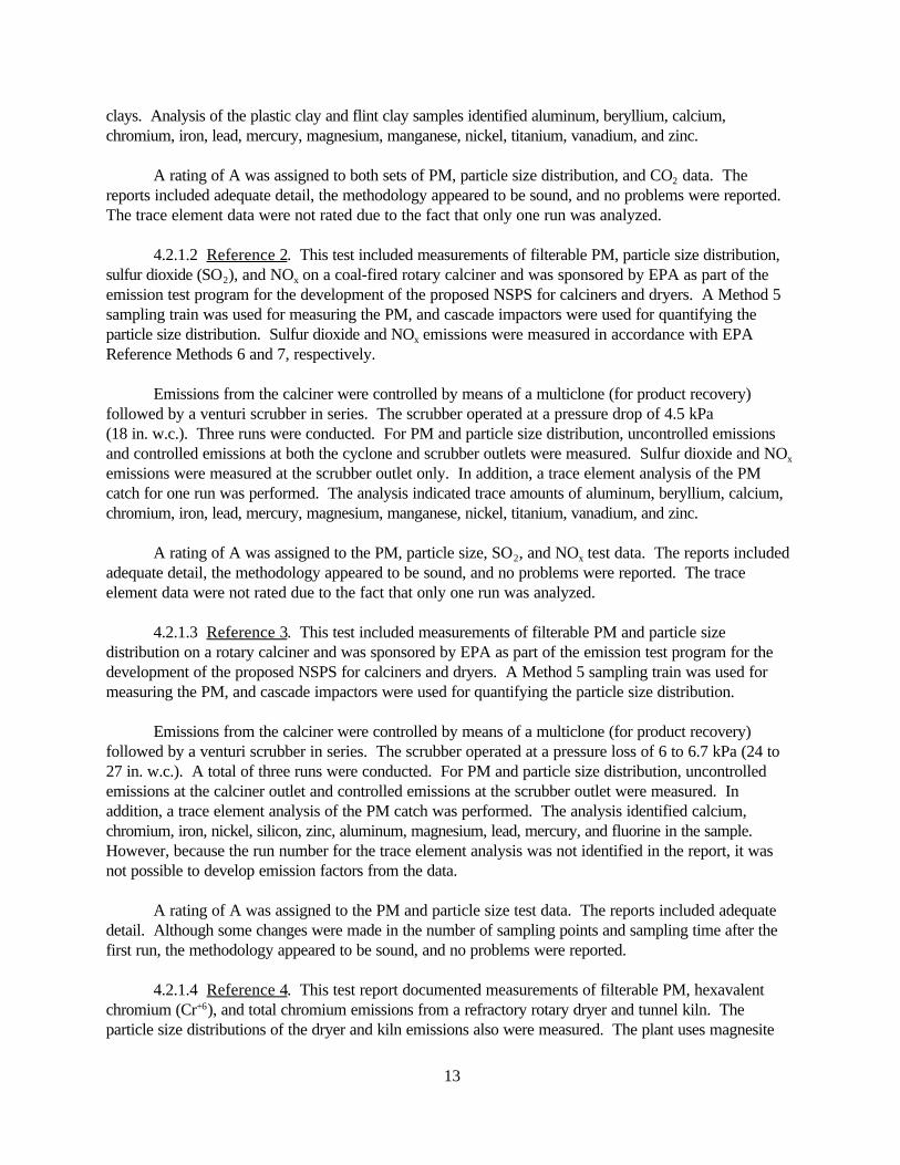
4.2.1.1 Reference 1. This test report included measurements of filterable PM, particle sizedistribution, and carbon dioxide (CO2) on a rotary dryer and was sponsored by EPA as part of theemission test program for the development of the proposed NSPS for calciners and dryers. Emissionrates were measured for two types of fire clay used in refractory manufacturing--flint clay and plasticclay. A Method 5 sampling train was used for measuring the PM, and cascade impactors were used forquantifying the particle size distribution. The CO2 emissions were measured using Method 3A (instrumentanalyzer).
Emissions from the dryer were controlled by means of a cyclone (for product recovery) followedby a wet scrubber in series. The wet scrubber operated with a pressure drop of 2.7 to 3.2 kilopascals(kPa) (11 to 13 inches of water [in. w.c.]). Three runs were conducted on each of the two clays. Uncontrolled emissions and controlled emissions, at both the cyclone and scrubber outlets, weremeasured. In addition, a trace element analysis of the PM catch was performed for each of the two
13
clays. Analysis of the plastic clay and flint clay samples identified aluminum, beryllium, calcium,chromium, iron, lead, mercury, magnesium, manganese, nickel, titanium, vanadium, and zinc.
A rating of A was assigned to both sets of PM, particle size distribution, and CO2 data. Thereports included adequate detail, the methodology appeared to be sound, and no problems were reported. The trace element data were not rated due to the fact that only one run was analyzed.
4.2.1.2 Reference 2. This test included measurements of filterable PM, particle size distribution,sulfur dioxide (SO2), and NOx on a coal-fired rotary calciner and was sponsored by EPA as part of theemission test program for the development of the proposed NSPS for calciners and dryers. A Method 5sampling train was used for measuring the PM, and cascade impactors were used for quantifying theparticle size distribution. Sulfur dioxide and NOx emissions were measured in accordance with EPAReference Methods 6 and 7, respectively.
Emissions from the calciner were controlled by means of a multiclone (for product recovery)followed by a venturi scrubber in series. The scrubber operated at a pressure drop of 4.5 kPa(18 in. w.c.). Three runs were conducted. For PM and particle size distribution, uncontrolled emissionsand controlled emissions at both the cyclone and scrubber outlets were measured. Sulfur dioxide and NOx
emissions were measured at the scrubber outlet only. In addition, a trace element analysis of the PMcatch for one run was performed. The analysis indicated trace amounts of aluminum, beryllium, calcium,chromium, iron, lead, mercury, magnesium, manganese, nickel, titanium, vanadium, and zinc.
A rating of A was assigned to the PM, particle size, SO2, and NOx test data. The reports includedadequate detail, the methodology appeared to be sound, and no problems were reported. The traceelement data were not rated due to the fact that only one run was analyzed.
4.2.1.3 Reference 3. This test included measurements of filterable PM and particle sizedistribution on a rotary calciner and was sponsored by EPA as part of the emission test program for thedevelopment of the proposed NSPS for calciners and dryers. A Method 5 sampling train was used formeasuring the PM, and cascade impactors were used for quantifying the particle size distribution.
Emissions from the calciner were controlled by means of a multiclone (for product recovery)followed by a venturi scrubber in series. The scrubber operated at a pressure loss of 6 to 6.7 kPa (24 to27 in. w.c.). A total of three runs were conducted. For PM and particle size distribution, uncontrolledemissions at the calciner outlet and controlled emissions at the scrubber outlet were measured. Inaddition, a trace element analysis of the PM catch was performed. The analysis identified calcium,chromium, iron, nickel, silicon, zinc, aluminum, magnesium, lead, mercury, and fluorine in the sample. However, because the run number for the trace element analysis was not identified in the report, it wasnot possible to develop emission factors from the data.
A rating of A was assigned to the PM and particle size test data. The reports included adequatedetail. Although some changes were made in the number of sampling points and sampling time after thefirst run, the methodology appeared to be sound, and no problems were reported.
4.2.1.4 Reference 4. This test report documented measurements of filterable PM, hexavalentchromium (Cr+6), and total chromium emissions from a refractory rotary dryer and tunnel kiln. Theparticle size distributions of the dryer and kiln emissions also were measured. The plant uses magnesite

14
and chromite ores to manufacture chromite-magnesite refractory brick. The chromite content of thematerial processed varied from 14.5 to 46.3 percent. The test was sponsored by EPA as part of thescreening study for industrial sources of chromium emissions.
A Method 5 sampling train (front half only) was used to measure filterable PM emissions. TheMethod 5 filter catch was analyzed for Cr+6 using the diphenylcarbazide colorimetric method and for totalchromium using neutron activation analysis. Particle size distribution was measured using cascadeimpactors with a preseparator.
Both uncontrolled and controlled (cyclone followed by a fabric filter) dryer PM emissions weresampled. However, because the controlled emissions included the dryer exhaust and the emissions fromfive material handling points, the emission factors developed from the controlled data are of limited use. Four test runs were conducted at both the cyclone inlet and fabric filter outlet. Three test runs ofuncontrolled filterable PM emissions from a tunnel kiln also were conducted. In addition, four particle sizedistribution runs were conducted on the dryer exhaust and fabric filter outlet, and three particle sizedistribution runs were conducted on the kiln exhaust.
The PM and particle size distribution data are rated A. The data are presented in adequate detailand a sound methodology was used. The Cr+6 and total chromium data are rated C due to the fact thatthe methods used were still under development at the time of the test.
4.2.2 Review of XATEF and SPECIATE Data Base Emission Factors
The only emission factors for refractory manufacturing included in the XATEF data base are forchromium emissions from chromite-magnesite brick and chromic oxide brick production. The source ofthese emission factors traces back to a 1973 document (EPA-450/3-74-012), which references the 1972version of AP-42. Because there is no further documentation of these emission factors in the AP-42background files, the original source of these data could not be identified. Therefore, these emissionfactors do not satisfy the minimum criteria for inclusion in AP-42.
The SPECIATE data base includes a number of emission factors for refractory manufacturing. However, the emission factors are based on speciation profiles for average mineral products industrysources, and therefore do not satisfy the minimum criteria for inclusion in AP-42.
4.2.3 Review of Test Data in AP-42 Background File
The previous version of AP-42 includes particulate emission factors for drying, crushing, electricarc melting, curing, and molding castable refractories. The emission factors are based on unpublisheddata from three stack tests that were conducted at a plant in Kentucky in 1967 and 1969. Thebackground file contains estimates of annual emissions from the same facility for 1968 but does notcontain any of the test data upon which the emission factors were based. Because of the lack ofdocumentation and the fact that the tests predate the development of EPA reference methods, the testmethod and representativeness of the data are highly suspect. Therefore, the emission factors based onthese data cannot be considered to be representative of the refractory manufacturing industry, so theywere deleted from the section.

15
4.2.4 Results of Data Analysis
Emission factors were developed for three types of refractory manufacturing sources: rotarydryers, rotary calciners, and tunnel kilns. The majority of these emission factors were developed for theprocessing of fire clay. However, emission factors also were developed for the processing of chromite-magnesite ore.
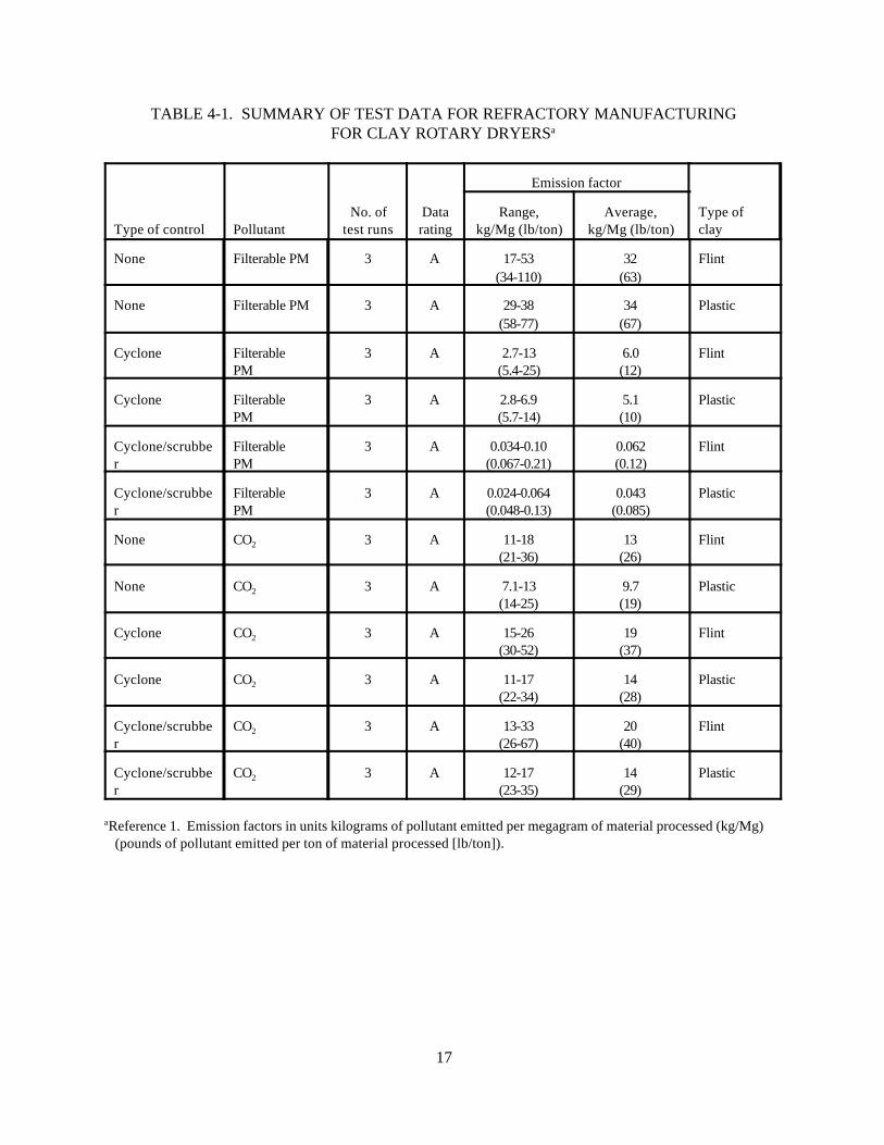
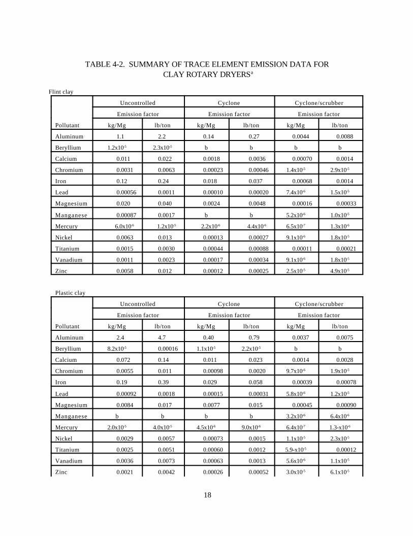
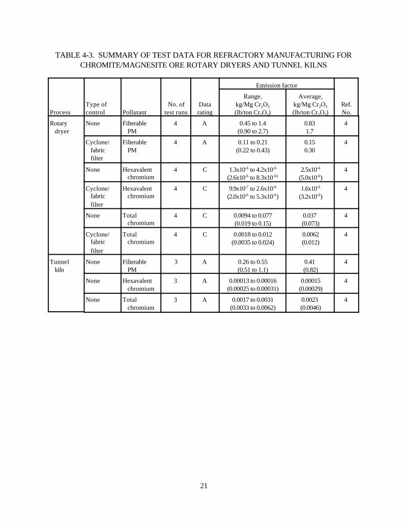
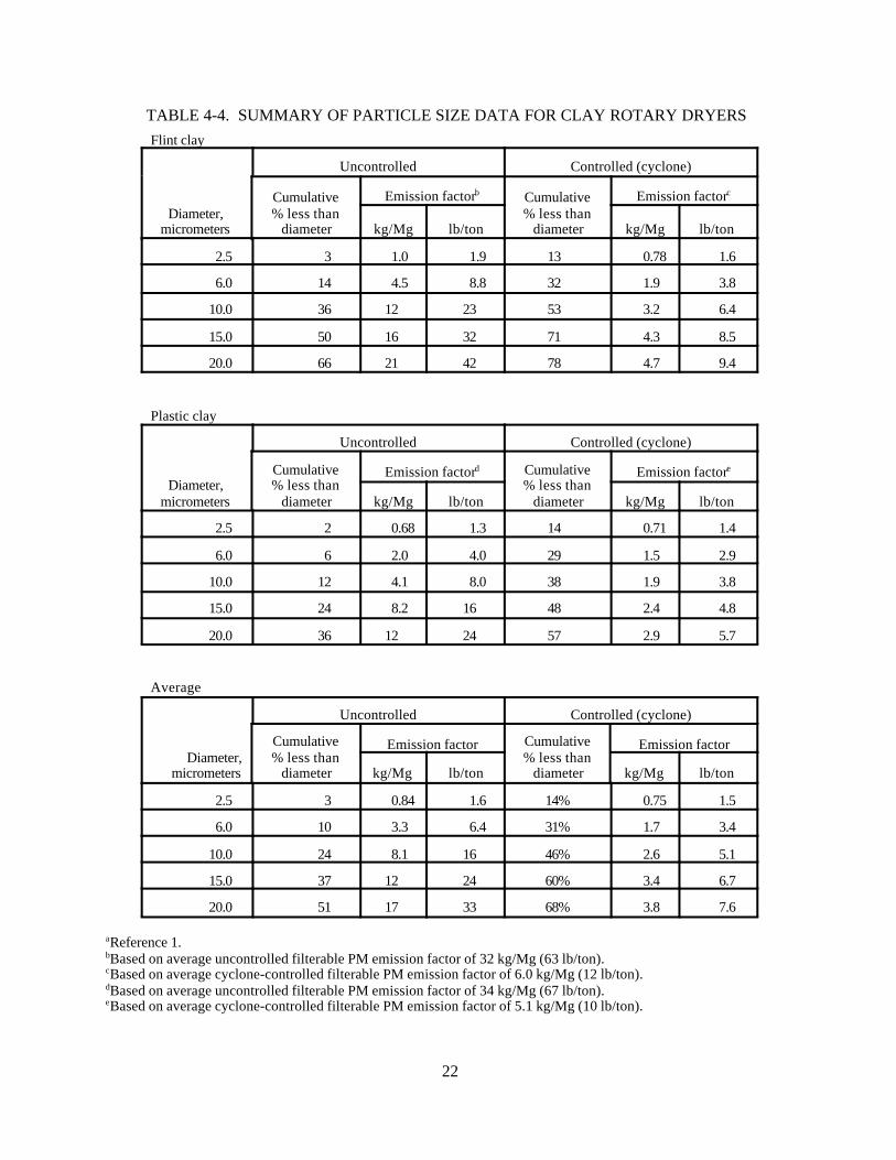
For rotary dryers, emission factors were developed for emissions of filterable PM, filterable PM-10, CO2, and several trace elements, including aluminum, beryllium, calcium, chromium, iron, lead,magnesium, manganese, mercury, nickel, titanium, vanadium, and zinc. These factors were developedfrom test data on two types of fire clay. In addition, rotary dryer emission factors for the drying ofchromite-magnesite ore were developed for filterable PM, filterable PM-10, hexavalent chromium, andtotal chromium. Particle size distribution for emissions from the drying of both fire clay and chromite-magnesite ore also were developed from the data. For the drying of fire clay, Table 4-1 summarizes thetest data on emissions of filterable PM, filterable PM-10, and CO2, and Table 4-2 summarizes the data ontrace element emissions. Although separate data are presented in Table 4-1 for CO2 emissions fromuncontrolled and controlled rotary dryers, all the data are considered to be uncontrolled, because thecontrol devices used (cyclones and scrubbers) achieve only incidental control of CO2 emissions. Fortunnel kilns, emission factors were developed for filterable PM, filterable PM-10, hexavalent chromium,and total chromium emissions from the firing of chromite-magnesite ore. Particle size distribution foremissions from the tunnel kilns firing chromite-magnesite ore also were developed from the data. Table4-3 summarizes the test data on emissions of filterable PM, filterable PM-10, hexavalent chromium, andtotal chromium from the drying of chromite-magnesite ore. Table 4-4 summarizes the particle sizedistribution data for the drying of fire clay, and Table 4-5 summarizes the particle size distribution data fortunnel kiln emissions.
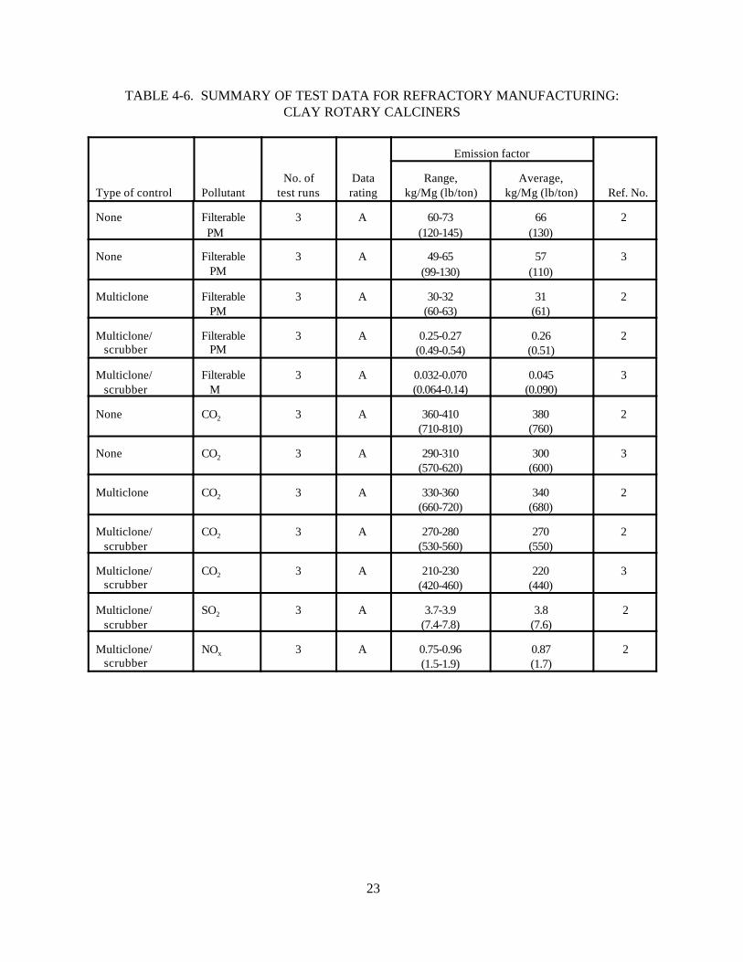
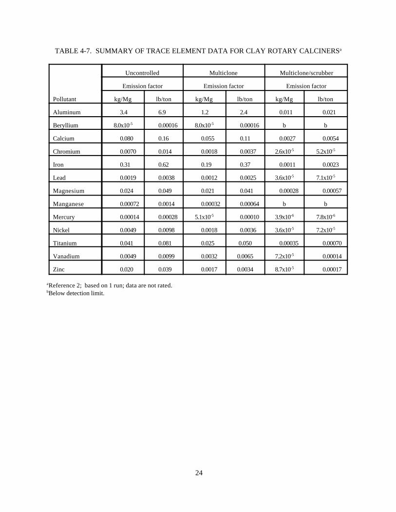
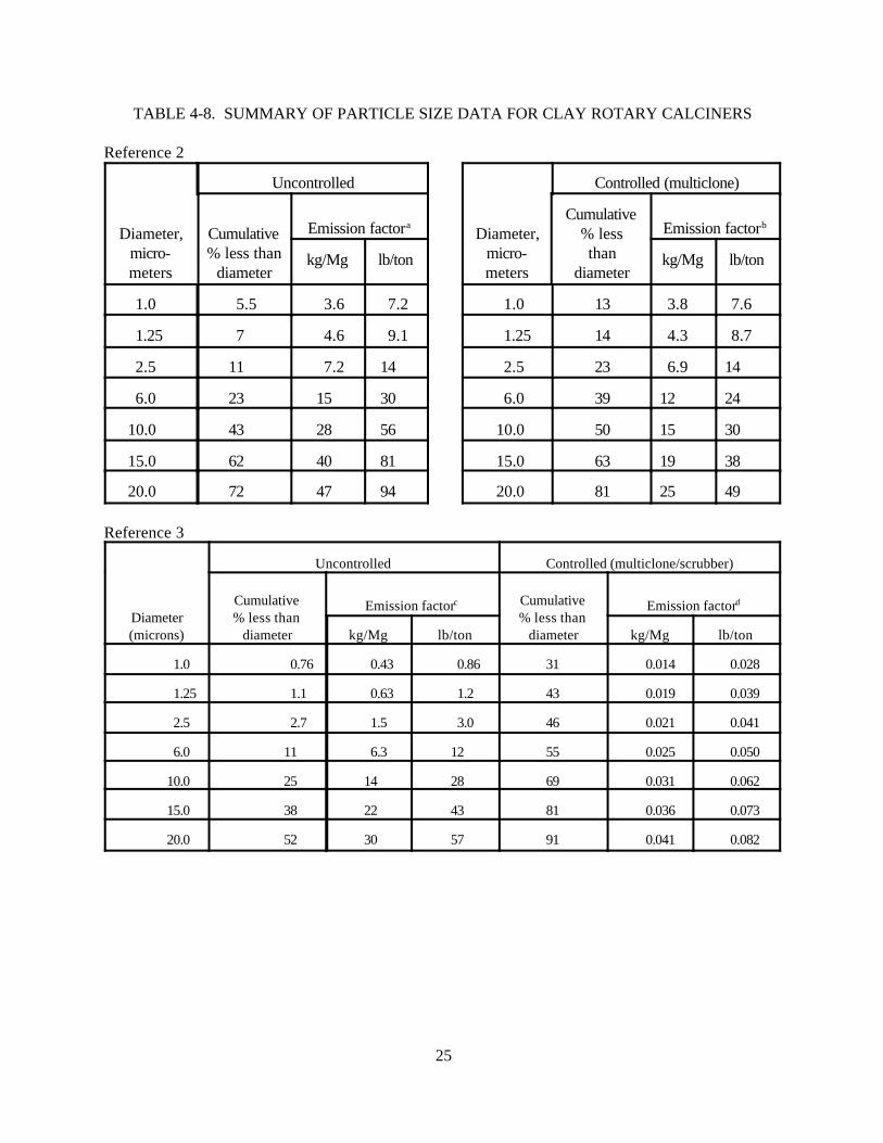
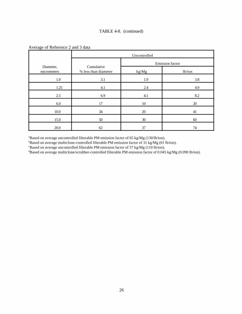
For rotary calciners, emission factors were developed for emissions of filterable PM, filterablePM-10, CO2, SO2, NOx, and several trace elements, including aluminum, beryllium, calcium, chromium,iron, lead, magnesium, manganese, mercury, nickel, titanium, vanadium, and zinc. These factors weredeveloped from test data on the calcining of fire clay. Particle size distribution for emissions fromcalcining fire clay also was developed from the data. For calcining fire clay, Table 4-6 summarizes thetest data on emissions of filterable PM, filterable PM-10, SO2, NOx, and CO2, and Table 4-7 summarizesthe data on trace element emissions. Although separate data are presented in Table 4-6 for CO2
emissions from uncontrolled and controlled rotary calciners, all the data is considered to be uncontrolled,because the control devices used (multiclones and scrubbers) achieve only incidental control of CO2
emissions. Table 4-8 summarizes the particle size distribution data for the calcining of fire clay.
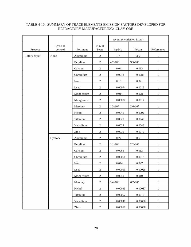
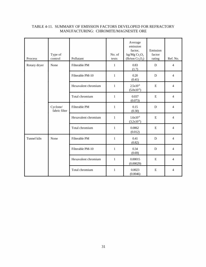
Although the emission factors discussed above for filterable PM, filterable PM-10, CO2, SO2, andNOx, are developed from A-rated test data, each of these factors is based on only one or two emissiontests. Because of the relatively large number of refractory manufacturing plants (280), it is likely that theemission factors do not represent a random sample of the industry. For this reason, these emissionfactors are all assigned a quality rating of D. The emission factors developed for hexavalent chromiumand total chromium emissions are developed from C-rated data. For this reason, these emission factorsare rated E. Table 4-9 summarizes the emission factors developed for emissions of filterable PM,filterable PM-10, CO2, SO2, and NOx from the processing of fire clay; Table 4-10 summarizes theemission summarizes the emission factors developed for emissions of filterable PM, filterable PM-10,hexavalent chromium, and total chromium from the processing of chromite-magnesite ore. The emission

16
factors presented in Tables 4-4, 4-5, 4-8, 4-9, and 4-11 are incorporated into the revised AP-42 section onrefractory manufacturing. Because the trace element emission factors are based on unrated data, theseemission factors have not been incorporated into the revised AP-42 section. As discussed above, therefractory manufacturing emission factors in the previous version of AP-42 are highly suspect, and,therefore, have been deleted from the revised section.
17
TABLE 4-1. SUMMARY OF TEST DATA FOR REFRACTORY MANUFACTURINGFOR CLAY ROTARY DRYERSa
Type of control PollutantNo. of
test runsDatarating
Emission factor
Type of clay
Range,kg/Mg (lb/ton)
Average,kg/Mg (lb/ton)
None Filterable PM 3 A 17-53(34-110)
32(63)
Flint
None Filterable PM 3 A 29-38(58-77)
34(67)
Plastic
Cyclone FilterablePM
3 A 2.7-13(5.4-25)
6.0(12)
Flint
Cyclone FilterablePM
3 A 2.8-6.9(5.7-14)
5.1(10)
Plastic
Cyclone/scrubber
FilterablePM
3 A 0.034-0.10(0.067-0.21)
0.062(0.12)
Flint
Cyclone/scrubber
FilterablePM
3 A 0.024-0.064(0.048-0.13)
0.043(0.085)
Plastic
None CO2 3 A 11-18(21-36)
13(26)
Flint
None CO2 3 A 7.1-13(14-25)
9.7(19)
Plastic
Cyclone CO2 3 A 15-26(30-52)
19(37)
Flint
Cyclone CO2 3 A 11-17(22-34)
14(28)
Plastic
Cyclone/scrubber
CO2 3 A 13-33(26-67)
20(40)
Flint
Cyclone/scrubber
CO2 3 A 12-17(23-35)
14(29)
Plastic
aReference 1. Emission factors in units kilograms of pollutant emitted per megagram of material processed (kg/Mg)(pounds of pollutant emitted per ton of material processed [lb/ton]).
18
TABLE 4-2. SUMMARY OF TRACE ELEMENT EMISSION DATA FOR CLAY ROTARY DRYERSa
Flint clay
Uncontrolled Cyclone Cyclone/scrubber
Emission factor Emission factor Emission factor
Pollutant kg/Mg lb/ton kg/Mg lb/ton kg/Mg lb/ton
Aluminum 1.1 2.2 0.14 0.27 0.0044 0.0088
Beryllium 1.2x10⁻⁵ 2.3x10⁻⁵ b b b b
Calcium 0.011 0.022 0.0018 0.0036 0.00070 0.0014
Chromium 0.0031 0.0063 0.00023 0.00046 1.4x10⁻⁵ 2.9x10⁻⁵
Iron 0.12 0.24 0.018 0.037 0.00068 0.0014
Lead 0.00056 0.0011 0.00010 0.00020 7.4x10⁻⁶ 1.5x10⁻⁵
Magnesium 0.020 0.040 0.0024 0.0048 0.00016 0.00033
Manganese 0.00087 0.0017 b b 5.2x10⁻⁶ 1.0x10⁻⁵
Mercury 6.0x10⁻⁶ 1.2x10⁻⁵ 2.2x10⁻⁶ 4.4x10⁻⁶ 6.5x10⁻⁷ 1.3x10⁻⁶
Nickel 0.0063 0.013 0.00013 0.00027 9.1x10⁻⁶ 1.8x10⁻⁵
Titanium 0.0015 0.0030 0.00044 0.00088 0.00011 0.00021
Vanadium 0.0011 0.0023 0.00017 0.00034 9.1x10⁻⁶ 1.8x10⁻⁵
Zinc 0.0058 0.012 0.00012 0.00025 2.5x10⁻⁵ 4.9x10⁻⁵
Plastic clay
Uncontrolled Cyclone Cyclone/scrubber
Emission factor Emission factor Emission factor
Pollutant kg/Mg lb/ton kg/Mg lb/ton kg/Mg lb/ton
Aluminum 2.4 4.7 0.40 0.79 0.0037 0.0075
Beryllium 8.2x10⁻⁵ 0.00016 1.1x10⁻⁵ 2.2x10⁻⁵ b b
Calcium 0.072 0.14 0.011 0.023 0.0014 0.0028
Chromium 0.0055 0.011 0.00098 0.0020 9.7x10⁻⁶ 1.9x10⁻⁵
Iron 0.19 0.39 0.029 0.058 0.00039 0.00078
Lead 0.00092 0.0018 0.00015 0.00031 5.8x10⁻⁶ 1.2x10⁻⁵
Magnesium 0.0084 0.017 0.0077 0.015 0.00045 0.00090
Manganese b b b b 3.2x10⁻⁶ 6.4x10⁻⁶
Mercury 2.0x10⁻⁵ 4.0x10⁻⁵ 4.5x10⁻⁶ 9.0x10⁻⁶ 6.4x10⁻⁷ 1.3-x10-6
Nickel 0.0029 0.0057 0.00073 0.0015 1.1x10⁻⁵ 2.3x10⁻⁵
Titanium 0.0025 0.0051 0.00060 0.0012 5.9-x10-5 0.00012
Vanadium 0.0036 0.0073 0.00063 0.0013 5.6x10⁻⁶ 1.1x10⁻⁵
Zinc 0.0021 0.0042 0.00026 0.00052 3.0x10⁻⁵ 6.1x10⁻⁵

TABLE 4-2 (continued)
20
Average of results of plastic and flint clays
Uncontrolled Cyclone Cyclone/scrubber
Emission factor Emission factor Emission factor
Pollutant kg/Mg lb/ton kg/Mg lb/ton kg/Mg lb/ton
Aluminum 1.7 3.5 0.27 0.53 0.0041 0.0081
Beryllium 4.7x10⁻⁵ 9.3x10⁻⁵ 1.1x10⁻⁵ 2.2x10⁻⁵ b b
Calcium 0.041 0.083 0.0066 0.013 0.0011 0.0021
Chromium 0.0043 0.0087 0.00061 0.0012 1.2x10⁻⁵ 2.4x10⁻⁵
Iron 0.16 0.32 0.024 0.047 0.00053 0.0011
Lead 0.00074 0.0015 0.00013 0.00025 6.6x10⁻⁶ 1.3x10⁻⁵
Magnesium 0.014 0.028 0.0051 0.010 0.00031 0.00061
Manganese 0.00087 0.0017 b b 4.2x10⁻⁶ 8.2x10⁻⁶
Mercury 1.3x10⁻⁵ 2.6x10⁻⁵ 3.4x10⁻⁶ 6.7x10⁻⁶ 6.5x10⁻⁷ 1.3x10⁻⁶
Nickel 0.0046 0.0092 0.00043 0.00087 1.0x10⁻⁵ 2.0x10⁻⁵
Titanium 0.0020 0.0040 0.00052 0.0010 8.3x10⁻⁵ 0.00017
Vanadium 0.0024 0.0048 0.00040 0.00080 7.4x10⁻⁶ 1.5x10⁻⁵
Zinc 0.0039 0.0079 0.00019 0.00038 2.8x10⁻⁵ 5.5x10⁻⁵
aBased on 1 run; data are not rated. Emission factors in units kilograms of pollutant emitted for megagram of material processed (kg/Mg) (pounds of pollutant emitted per ton of material processed [lb/ton]).bBelow detection limit.
21
TABLE 4-3. SUMMARY OF TEST DATA FOR REFRACTORY MANUFACTURING FORCHROMITE/MAGNESITE ORE ROTARY DRYERS AND TUNNEL KILNS
ProcessType ofcontrol Pollutant
No. oftest runs
Datarating
Emission factor
Ref.No.
Range,kg/Mg Cr2O3
(lb/ton Cr2O3)
Average,kg/Mg Cr2O3
(lb/ton Cr2O3)
Rotarydryer
None FilterablePM
4 A 0.45 to 1.4(0.90 to 2.7)
0.83 1.7
4
Cyclone/fabricfilter
FilterablePM
4 A 0.11 to 0.21(0.22 to 0.43)
0.15 0.30
4
None Hexavalentchromium
4 C 1.3x10⁻⁶ to 4.2x10⁻⁶
(2.6x10⁻⁶ to 8.3x10⁻⁶)2.5x10⁻⁶
(5.0x10⁻⁶)4
Cyclone/fabricfilter
Hexavalentchromium
4 C 9.9x10⁻⁷ to 2.6x10⁻⁶
(2.0x10⁻⁶ to 5.3x10⁻⁶)1.6x10⁻⁶
(3.2x10⁻⁶)4
None Total chromium
4 C 0.0094 to 0.077(0.019 to 0.15)
0.037 (0.073)
4
Cyclone/fabricfilter
Totalchromium
4 C 0.0018 to 0.012(0.0035 to 0.024)
0.0062(0.012)
4
Tunnelkiln
None FilterablePM
3 A 0.26 to 0.55(0.51 to 1.1)
0.41 (0.82)
4
None Hexavalentchromium
3 A 0.00013 to 0.00016(0.00025 to 0.00031)
0.00015(0.00029)
4
None Totalchromium
3 A 0.0017 to 0.0031(0.0033 to 0.0062)
0.0023 (0.0046)
4
22
TABLE 4-4. SUMMARY OF PARTICLE SIZE DATA FOR CLAY ROTARY DRYERS
Flint clay
Uncontrolled Controlled (cyclone)
Diameter,micrometers
Cumulative% less than
diameter
Emission factorb Cumulative% less than
diameter
Emission factorc
kg/Mg lb/ton kg/Mg lb/ton
2.5 3 1.0 1.9 13 0.78 1.6
6.0 14 4.5 8.8 32 1.9 3.8
10.0 36 12 23 53 3.2 6.4
15.0 50 16 32 71 4.3 8.5
20.0 66 21 42 78 4.7 9.4
Plastic clay
Diameter,micrometers
Uncontrolled Controlled (cyclone)
Cumulative% less than
diameter
Emission factord Cumulative% less than
diameter
Emission factore
kg/Mg lb/ton kg/Mg lb/ton
2.5 2 0.68 1.3 14 0.71 1.4
6.0 6 2.0 4.0 29 1.5 2.9
10.0 12 4.1 8.0 38 1.9 3.8
15.0 24 8.2 16 48 2.4 4.8
20.0 36 12 24 57 2.9 5.7
Average
Diameter,micrometers
Uncontrolled Controlled (cyclone)
Cumulative% less than
diameter
Emission factor Cumulative% less than
diameter
Emission factor
kg/Mg lb/ton kg/Mg lb/ton
2.5 3 0.84 1.6 14% 0.75 1.5
6.0 10 3.3 6.4 31% 1.7 3.4
10.0 24 8.1 16 46% 2.6 5.1
15.0 37 12 24 60% 3.4 6.7
20.0 51 17 33 68% 3.8 7.6
aReference 1.bBased on average uncontrolled filterable PM emission factor of 32 kg/Mg (63 lb/ton).cBased on average cyclone-controlled filterable PM emission factor of 6.0 kg/Mg (12 lb/ton).dBased on average uncontrolled filterable PM emission factor of 34 kg/Mg (67 lb/ton).eBased on average cyclone-controlled filterable PM emission factor of 5.1 kg/Mg (10 lb/ton).
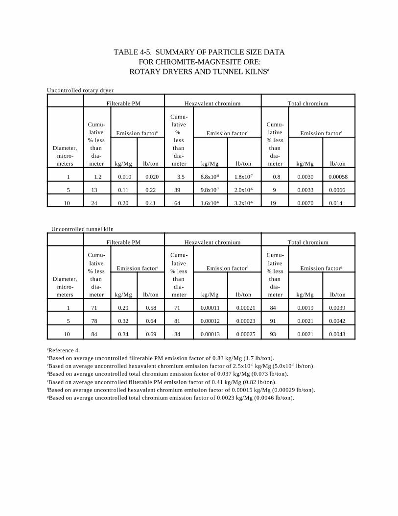
TABLE 4-5. SUMMARY OF PARTICLE SIZE DATAFOR CHROMITE-MAGNESITE ORE:
ROTARY DRYERS AND TUNNEL KILNSa
Uncontrolled rotary dryer
Filterable PM Hexavalent chromium Total chromium
Diameter,micro-meters
Cumu-lative% lessthandia-
meter
Emission factorb
Cumu-lative
% lessthandia-
meter
Emission factorc
Cumu-lative% lessthandia-
meter
Emission factord
kg/Mg lb/ton kg/Mg lb/ton kg/Mg lb/ton
1 1.2 0.010 0.020 3.5 8.8x10⁻⁸ 1.8x10⁻⁷ 0.8 0.0030 0.00058
5 13 0.11 0.22 39 9.8x10⁻⁷ 2.0x10⁻⁶ 9 0.0033 0.0066
10 24 0.20 0.41 64 1.6x10⁻⁶ 3.2x10⁻⁶ 19 0.0070 0.014
Uncontrolled tunnel kiln
Filterable PM Hexavalent chromium Total chromium
Diameter,micro-meters
Cumu-lative% lessthandia-
meter
Emission factore
Cumu-lative% lessthandia-
meter
Emission factorf
Cumu-lative% lessthandia-
meter
Emission factorg
kg/Mg lb/ton kg/Mg lb/ton kg/Mg lb/ton
1 71 0.29 0.58 71 0.00011 0.00021 84 0.0019 0.0039
5 78 0.32 0.64 81 0.00012 0.00023 91 0.0021 0.0042
10 84 0.34 0.69 84 0.00013 0.00025 93 0.0021 0.0043
aReference 4.bBased on average uncontrolled filterable PM emission factor of 0.83 kg/Mg (1.7 lb/ton).cBased on average uncontrolled hexavalent chromium emission factor of 2.5x10⁻⁶ kg/Mg (5.0x10⁻⁶ lb/ton).dBased on average uncontrolled total chromium emission factor of 0.037 kg/Mg (0.073 lb/ton).eBased on average uncontrolled filterable PM emission factor of 0.41 kg/Mg (0.82 lb/ton).fBased on average uncontrolled hexavalent chromium emission factor of 0.00015 kg/Mg (0.00029 lb/ton).gBased on average uncontrolled total chromium emission factor of 0.0023 kg/Mg (0.0046 lb/ton).
23
TABLE 4-6. SUMMARY OF TEST DATA FOR REFRACTORY MANUFACTURING:CLAY ROTARY CALCINERS
Type of control PollutantNo. of
test runsDatarating
Emission factor
Ref. No.Range,
kg/Mg (lb/ton)Average,
kg/Mg (lb/ton)
None Filterable PM
3 A 60-73(120-145)
66(130)
2
None FilterablePM
3 A 49-65(99-130)
57(110)
3
Multiclone FilterablePM
3 A 30-32(60-63)
31(61)
2
Multiclone/scrubber
FilterablePM
3 A 0.25-0.27(0.49-0.54)
0.26(0.51)
2
Multiclone/scrubber
FilterableM
3 A 0.032-0.070(0.064-0.14)
0.045(0.090)
3
None CO2 3 A 360-410(710-810)
380(760)
2
None CO2 3 A 290-310(570-620)
300(600)
3
Multiclone CO2 3 A 330-360(660-720)
340(680)
2
Multiclone/scrubber
CO2 3 A 270-280(530-560)
270(550)
2
Multiclone/scrubber
CO2 3 A 210-230(420-460)
220(440)
3
Multiclone/scrubber
SO2 3 A 3.7-3.9(7.4-7.8)
3.8(7.6)
2
Multiclone/scrubber
NOx 3 A 0.75-0.96(1.5-1.9)
0.87(1.7)
2
24
TABLE 4-7. SUMMARY OF TRACE ELEMENT DATA FOR CLAY ROTARY CALCINERSa
Pollutant
Uncontrolled Multiclone Multiclone/scrubber
Emission factor Emission factor Emission factor
kg/Mg lb/ton kg/Mg lb/ton kg/Mg lb/ton
Aluminum 3.4 6.9 1.2 2.4 0.011 0.021
Beryllium 8.0x10⁻⁵ 0.00016 8.0x10⁻⁵ 0.00016 b b
Calcium 0.080 0.16 0.055 0.11 0.0027 0.0054
Chromium 0.0070 0.014 0.0018 0.0037 2.6x10⁻⁵ 5.2x10⁻⁵
Iron 0.31 0.62 0.19 0.37 0.0011 0.0023
Lead 0.0019 0.0038 0.0012 0.0025 3.6x10⁻⁵ 7.1x10⁻⁵
Magnesium 0.024 0.049 0.021 0.041 0.00028 0.00057
Manganese 0.00072 0.0014 0.00032 0.00064 b b
Mercury 0.00014 0.00028 5.1x10⁻⁵ 0.00010 3.9x10⁻⁶ 7.8x10⁻⁶
Nickel 0.0049 0.0098 0.0018 0.0036 3.6x10⁻⁵ 7.2x10⁻⁵
Titanium 0.041 0.081 0.025 0.050 0.00035 0.00070
Vanadium 0.0049 0.0099 0.0032 0.0065 7.2x10⁻⁵ 0.00014
Zinc 0.020 0.039 0.0017 0.0034 8.7x10⁻⁵ 0.00017
aReference 2; based on 1 run; data are not rated.bBelow detection limit.
25
TABLE 4-8. SUMMARY OF PARTICLE SIZE DATA FOR CLAY ROTARY CALCINERS
Reference 2
Diameter,micro-meters
Uncontrolled
Diameter,micro-meters
Controlled (multiclone)
Cumulative% less than
diameter
Emission factoraCumulative
% lessthan
diameter
Emission factorb
kg/Mg lb/ton kg/Mg lb/ton
1.0 5.5 3.6 7.2 1.0 13 3.8 7.6
1.25 7 4.6 9.1 1.25 14 4.3 8.7
2.5 11 7.2 14 2.5 23 6.9 14
6.0 23 15 30 6.0 39 12 24
10.0 43 28 56 10.0 50 15 30
15.0 62 40 81 15.0 63 19 38
20.0 72 47 94 20.0 81 25 49
Reference 3
Uncontrolled Controlled (multiclone/scrubber)
Diameter(microns)
Cumulative% less than
diameter
Emission factorc Cumulative% less than
diameter
Emission factord
kg/Mg lb/ton kg/Mg lb/ton
1.0 0.76 0.43 0.86 31 0.014 0.028
1.25 1.1 0.63 1.2 43 0.019 0.039
2.5 2.7 1.5 3.0 46 0.021 0.041
6.0 11 6.3 12 55 0.025 0.050
10.0 25 14 28 69 0.031 0.062
15.0 38 22 43 81 0.036 0.073
20.0 52 30 57 91 0.041 0.082
26
TABLE 4-8. (continued)
Average of Reference 2 and 3 data
Diameter,micrometers
Uncontrolled
Cumulative% less than diameter
Emission factor
kg/Mg lb/ton
1.0 3.1 1.9 3.8
1.25 4.1 2.4 4.9
2.5 6.9 4.1 8.2
6.0 17 10 20
10.0 34 20 41
15.0 50 30 60
20.0 62 37 74
aBased on average uncontrolled filterable PM emission factor of 65 kg/Mg (130/lb/ton).bBased on average multiclone-controlled filterable PM emission factor of 31 kg/Mg (61 lb/ton).cBased on average uncontrolled filterable PM emission factor of 57 kg/Mg (110 lb/ton).dBased on average multiclone/scrubber-controlled filterable PM emission factor of 0.045 kg/Mg (0.090 lb/ton).
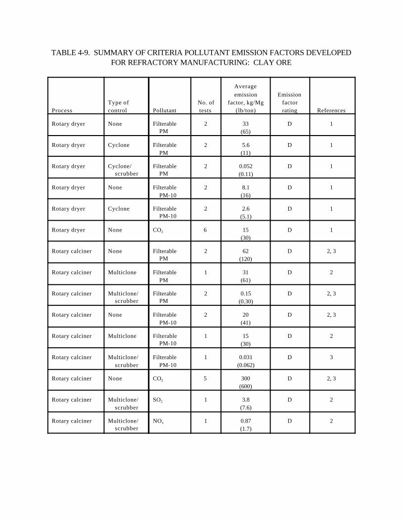
TABLE 4-9. SUMMARY OF CRITERIA POLLUTANT EMISSION FACTORS DEVELOPEDFOR REFRACTORY MANUFACTURING: CLAY ORE
ProcessType ofcontrol Pollutant
No. oftests
Averageemission
factor, kg/Mg(lb/ton)
Emissionfactorrating References
Rotary dryer None FilterablePM
2 33(65)
D 1
Rotary dryer Cyclone FilterablePM
2 5.6(11)
D 1
Rotary dryer Cyclone/scrubber
FilterablePM
2 0.052(0.11)
D 1
Rotary dryer None FilterablePM-10
2 8.1(16)
D 1
Rotary dryer Cyclone FilterablePM-10
2 2.6(5.1)
D 1
Rotary dryer None CO2 6 15(30)
D 1
Rotary calciner None FilterablePM
2 62(120)
D 2, 3
Rotary calciner Multiclone FilterablePM
1 31(61)
D 2
Rotary calciner Multiclone/scrubber
FilterablePM
2 0.15(0.30)
D 2, 3
Rotary calciner None FilterablePM-10
2 20(41)
D 2, 3
Rotary calciner Multiclone Filterable PM-10
1 15(30)
D 2
Rotary calciner Multiclone/scrubber
FilterablePM-10
1 0.031(0.062)
D 3
Rotary calciner None CO2 5 300(600)
D 2, 3
Rotary calciner Multiclone/scrubber
SO2 1 3.8(7.6)
D 2
Rotary calciner Multiclone/scrubber
NOx 1 0.87(1.7)
D 2
28
TABLE 4-10. SUMMARY OF TRACE ELEMENTS EMISSION FACTORS DEVELOPED FORREFRACTORY MANUFACTURING: CLAY ORE
Average emission factor
ProcessType ofcontrol Pollutant
No. ofTests kg/Mg lb/ton References
Rotary dryer None Aluminum 2 1.7 3.5 1
Berylium 2 4.7x10⁻⁵ 9.3x10⁻⁵ 1
Calcium 2 0.041 0.083 1
Chromium 2 0.0043 0.0087 1
Iron 2 0.16 0.32 1
Lead 2 0.00074 0.0015 1
Magnesium 2 0.014 0.028 1
Manganese 2 0.00087 0.0017 1
Mercury 2 1.3x10⁻⁵ 2.6x10⁻⁵ 1
Nickel 2 0.0046 0.0092 1
Titanium 2 0.0020 0.0040 1
Vanadium 2 0.0024 0.0048 1
Zinc 2 0.0039 0.0079 1
Cyclone Aluminum 2 0.27 0.53 1
Berylium 2 1.1x10⁻⁵ 2.2x10⁻⁵ 1
Calcium 2 0.0066 0.013 1
Chromium 2 0.00061 0.0012 1
Iron 2 0.024 0.047 1
Lead 2 0.00013 0.00025 1
Magnesium 2 0.0051 0.010 1
Mercury 2 3.4x10⁻⁶ 6.7x10⁻⁶ 1
Nickel 2 0.00043 0.00087 1
Titanium 2 0.00052 0.0010 1
Vanadium 2 0.00040 0.00080 1
Zinc 2 0.00019 0.00038 1
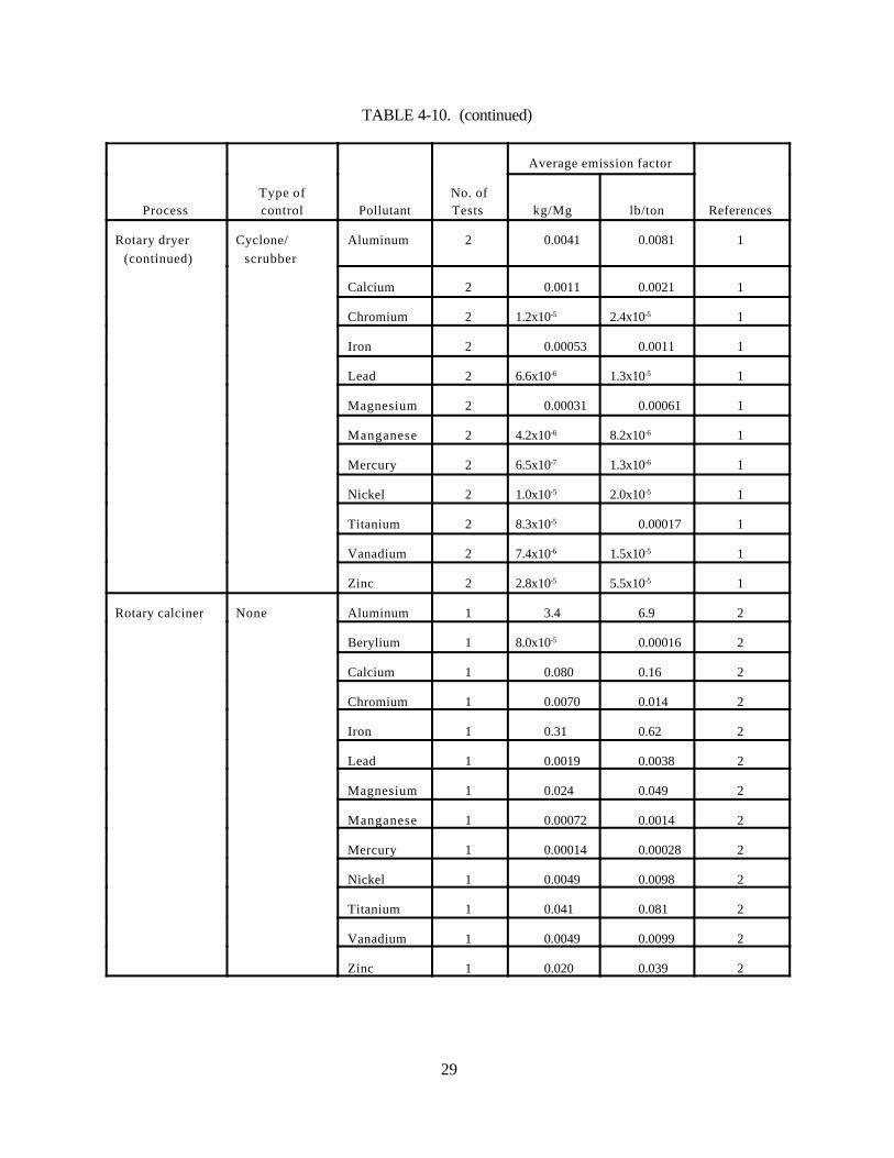
TABLE 4-10. (continued)
Average emission factor
ProcessType ofcontrol Pollutant
No. ofTests kg/Mg lb/ton References
29
Rotary dryer(continued)
Cyclone/scrubber
Aluminum 2 0.0041 0.0081 1
Calcium 2 0.0011 0.0021 1
Chromium 2 1.2x10⁻⁵ 2.4x10⁻⁵ 1
Iron 2 0.00053 0.0011 1
Lead 2 6.6x10⁻⁶ 1.3x10⁻⁵ 1
Magnesium 2 0.00031 0.00061 1
Manganese 2 4.2x10⁻⁶ 8.2x10⁻⁶ 1
Mercury 2 6.5x10⁻⁷ 1.3x10⁻⁶ 1
Nickel 2 1.0x10⁻⁵ 2.0x10⁻⁵ 1
Titanium 2 8.3x10⁻⁵ 0.00017 1
Vanadium 2 7.4x10⁻⁶ 1.5x10⁻⁵ 1
Zinc 2 2.8x10⁻⁵ 5.5x10⁻⁵ 1
Rotary calciner None Aluminum 1 3.4 6.9 2
Berylium 1 8.0x10⁻⁵ 0.00016 2
Calcium 1 0.080 0.16 2
Chromium 1 0.0070 0.014 2
Iron 1 0.31 0.62 2
Lead 1 0.0019 0.0038 2
Magnesium 1 0.024 0.049 2
Manganese 1 0.00072 0.0014 2
Mercury 1 0.00014 0.00028 2
Nickel 1 0.0049 0.0098 2
Titanium 1 0.041 0.081 2
Vanadium 1 0.0049 0.0099 2
Zinc 1 0.020 0.039 2
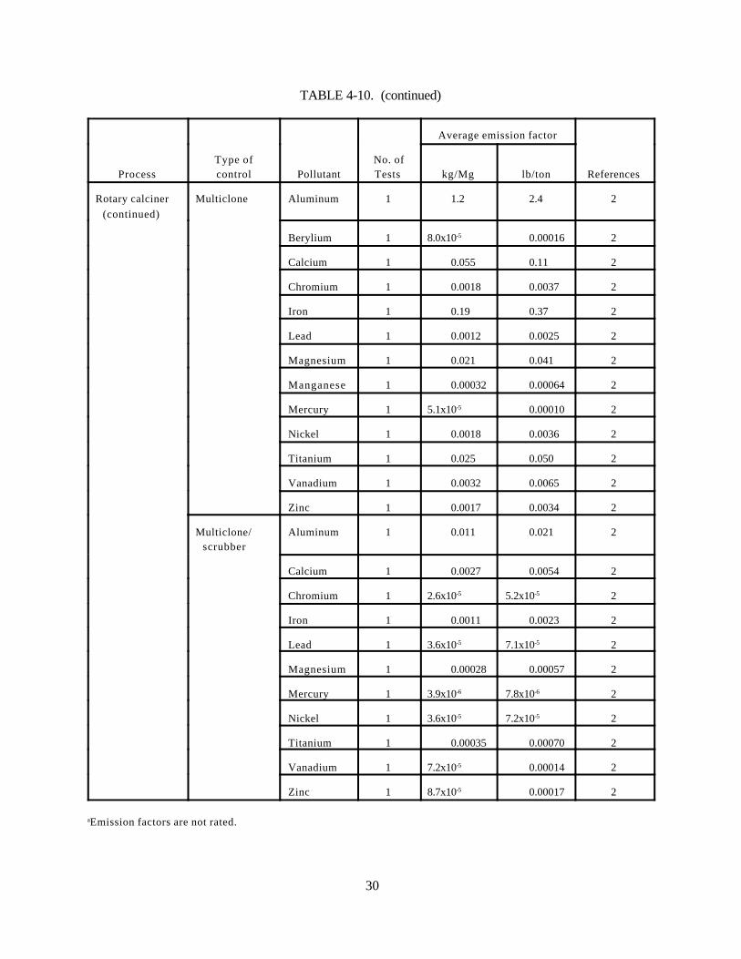
TABLE 4-10. (continued)
Average emission factor
ProcessType ofcontrol Pollutant
No. ofTests kg/Mg lb/ton References
30
Rotary calciner(continued)
Multiclone Aluminum 1 1.2 2.4 2
Berylium 1 8.0x10⁻⁵ 0.00016 2
Calcium 1 0.055 0.11 2
Chromium 1 0.0018 0.0037 2
Iron 1 0.19 0.37 2
Lead 1 0.0012 0.0025 2
Magnesium 1 0.021 0.041 2
Manganese 1 0.00032 0.00064 2
Mercury 1 5.1x10⁻⁵ 0.00010 2
Nickel 1 0.0018 0.0036 2
Titanium 1 0.025 0.050 2
Vanadium 1 0.0032 0.0065 2
Zinc 1 0.0017 0.0034 2
Multiclone/scrubber
Aluminum 1 0.011 0.021 2
Calcium 1 0.0027 0.0054 2
Chromium 1 2.6x10⁻⁵ 5.2x10⁻⁵ 2
Iron 1 0.0011 0.0023 2
Lead 1 3.6x10⁻⁵ 7.1x10⁻⁵ 2
Magnesium 1 0.00028 0.00057 2
Mercury 1 3.9x10⁻⁶ 7.8x10⁻⁶ 2
Nickel 1 3.6x10⁻⁵ 7.2x10⁻⁵ 2
Titanium 1 0.00035 0.00070 2
Vanadium 1 7.2x10⁻⁵ 0.00014 2
Zinc 1 8.7x10⁻⁵ 0.00017 2
aEmission factors are not rated.
31
TABLE 4-11. SUMMARY OF EMISSION FACTORS DEVELOPED FOR REFRACTORYMANUFACTURING: CHROMITE/MAGNESITE ORE
ProcessType ofcontrol Pollutant
No. oftests
Averageemissionfactor,
kg/Mg Cr2O3
(lb/ton Cr2O3)
Emissionfactorrating Ref. No.
Rotary dryer None Filterable PM 1 0.83(1.7)
D 4
Filterable PM-10 1 0.20(0.41)
D 4
Hexavalent chromium 1 2.5x10⁻⁶
(5.0x10⁻⁶)E 4
Total chromium 1 0.037(0.073)
E 4
Cyclone/fabric filter
Filterable PM 1 0.15(0.30)
D 4
Hexavalent chromium 1 1.6x10⁻⁶
(3.2x10⁻⁶)E 4
Total chromium 1 0.0062 (0.012)
E 4
Tunnel kiln None Filterable PM 1 0.41(0.82)
D 4
Filterable PM-10 1 0.34(0.69)
D 4
Hexavalent chromium 1 0.00015(0.00029)
E 4
Total chromium 1 0.0023(0.0046)
E 4
32
REFERENCES FOR SECTION 4
1. Calciners and Dryers Emission Test Report, North American Refractories Company, Farber,Missouri, EMB Report 84-CDR-14, U. S. Environmental Protection Agency, Research TrianglePark, NC, March 1984.
2. Emission Test Report: Plant A, Test 1, Confidential Business Information Files, Document No. C-7-12, ESD Project No. 81/08, U. S. Environmental Protection Agency, Research Triangle Park, NC.
3. Calciners and Dryers Emission Test Report, A. P. Green Company, Mexico, Missouri, EMBReport 83-CDR-1, U. S. Environmental Protection Agency, Research Triangle Park, NC, October1983.
4. Chromium Screening Study Test Report, Harbison-Walker Refractories, Baltimore, Maryland,EMB Report 85-CHM-12, U. S. Environmental Protection Agency, Research Triangle Park, NC,June 1985.
5. Emission Test Report: North American Refractories Company, Farber, Missouri, ConfidentialBusiness Information Files, Document No. C-10-6, ESD Project No. 81/08, U. S. EnvironmentalProtection Agency, Research Triangle Park, NC.
6. Emission Test Report: Plant A, Test 2, Confidential Business Information Files, Document No. C-7-12, ESD Project No. 81/08, U. S. Environmental Protection Agency, Research Triangle Park, NC.
7. Particulate Emissions Testing of the Rotary Kiln Cooler Stack, Harbison-Walker Refractories,Fulton, Missouri, Environmental Triple S Company, St. Louis, MO, December 1975.
8. Report of the Particulate Emissions Testing of the Rotary Kiln Stack, Harbison-WalkerRefractories, Fulton, Missouri, Environmental Triple S Company, St. Louis, MO, September 1974.

33
5. PROPOSED AP-42 SECTION 11.5
A proposed revision of the existing AP-42 Section 8.5, Castable Refractories, is presented in thefollowing pages as it would appear in the document.

Figure 2-1. Refractory manufacturing process flow diagram.1
3411.5 1/95
11.5 Refractory Manufacturing
11.5.1 Process Description1-2
Refractories are materials that provide linings for high-temperature furnaces and other processingunits. Refractories must be able to withstand physical wear, high temperatures (above 538EC [1000EF]),and corrosion by chemical agents. There are two general classifications of refractories, clay and nonclay. The six-digit source classification code (SCC) for refractory manufacturing is 3-05-005. Clay refractoriesare produced from fireclay (hydrous silicates of aluminum) and alumina (57 to 87.5 percent). Other clayminerals used in the production of refractories include kaolin, bentonite, ball clay, and common clay. Nonclay refractories are produced from a composition of alumina (<87.5 percent), mullite, chromite,magnesite, silica, silicon carbide, zircon, and other nonclays.
Refractories are produced in two basic forms, formed objects, and unformed granulated or plasticcompositions. The preformed products are called bricks and shapes. These products are used to formthe walls, arches, and floor tiles of various high-temperature process equipment. Unformed compositionsinclude mortars, gunning mixes, castables (refractory concretes), ramming mixes, and plastics. Theseproducts are cured in place to form a monolithic, internal structure after application.
Refractory manufacturing involves four processes: raw material processing, forming, firing, and finalprocessing. Figure 11.5-1
3611.5 1/95
illustrates the refractory manufacturing process. Raw material processing consists of crushing andgrinding raw materials, followed if necessary by size classification and raw materials calcining and drying. The processed raw material then may be dry-mixed with other minerals and chemical compounds,packaged, and shipped as product. All of these processes are not required for some refractory products.
Forming consists of mixing the raw materials and forming them into the desired shapes. This processfrequently occurs under wet or moist conditions. Firing involves heating the refractory material to high temperatures in a periodic (batch) or continuous tunnel kiln to form the ceramic bond thatgives the product its refractory properties. The final processing stage involves milling, grinding, andsandblasting of the finished product. This step keeps the product in correct shape and size after thermalexpansion has occurred. For certain products, final processing may also include product impregnationwith tar and pitch, and final packaging.
Two other types of refractory processes also warrant discussion. The first is production of fusedproducts. This process involves using an electric arc furnace to melt the refractory raw materials, thenpouring the melted materials into sand-forming molds. Another type of refractory process is ceramicfiber production. In this process, calcined kaolin is melted in an electric arc furnace. The molten clay iseither fiberized in a blowchamber with a centrifuge device or is dropped into an air jet and immediatelyblown into fine strands. After the blowchamber, the ceramic fiber may then be conveyed to an oven forcuring, which adds structural rigidity to the fibers. During the curing process, oils are used to lubricateboth the fibers and the machinery used to handle and form the fibers. The production of ceramic fiber forrefractory material is very similar to the production of mineral wool.
3811.5 1/95
11.5.2 Emissions And Controls2-6
The primary pollutant of concern in refractory manufacturing is particulate matter (PM). Particulatematter emissions occur during the crushing, grinding, screening, calcining, and drying of the raw materials; the drying and firing of the unfired "green" refractory bricks, tar and pitch operations;and finishing of the refractories (grinding, milling, and sandblasting).
Emissions from crushing and grinding operations generally are controlled with fabric filters. Productrecovery cyclones followed by wet scrubbers are used on calciners and dryers to control PM emissionsfrom these sources. The primary sources of PM emissions are the refractory firing kilns and electric arcfurnaces. Particulate matter emissions from kilns generally are not controlled. However, at least onerefractory manufacturer currently uses a multiple-stage scrubber to control kiln emissions. Particulatematter emissions from electric arc furnaces generally are controlled by a baghouse. Particulate removalof 87 percent and fluoride removal of greater than 99 percent have been reported at one facility that usesan ionizing wet scrubber.
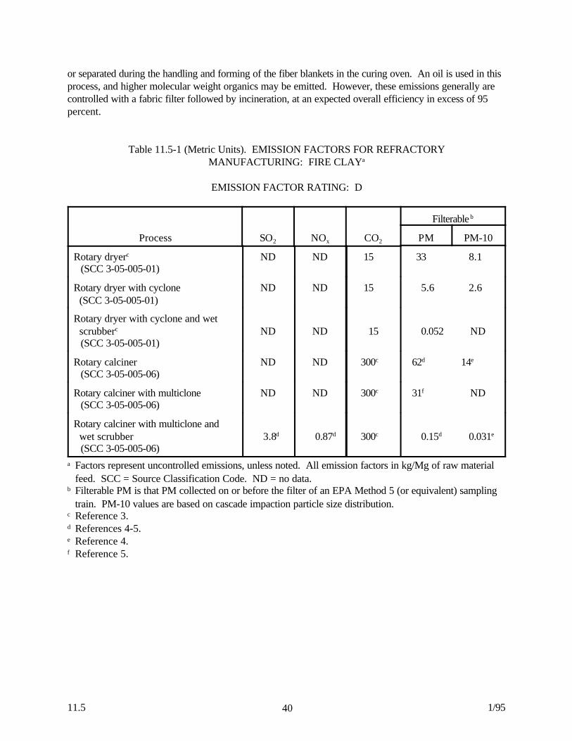
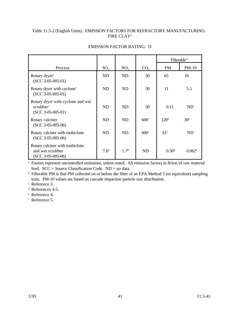
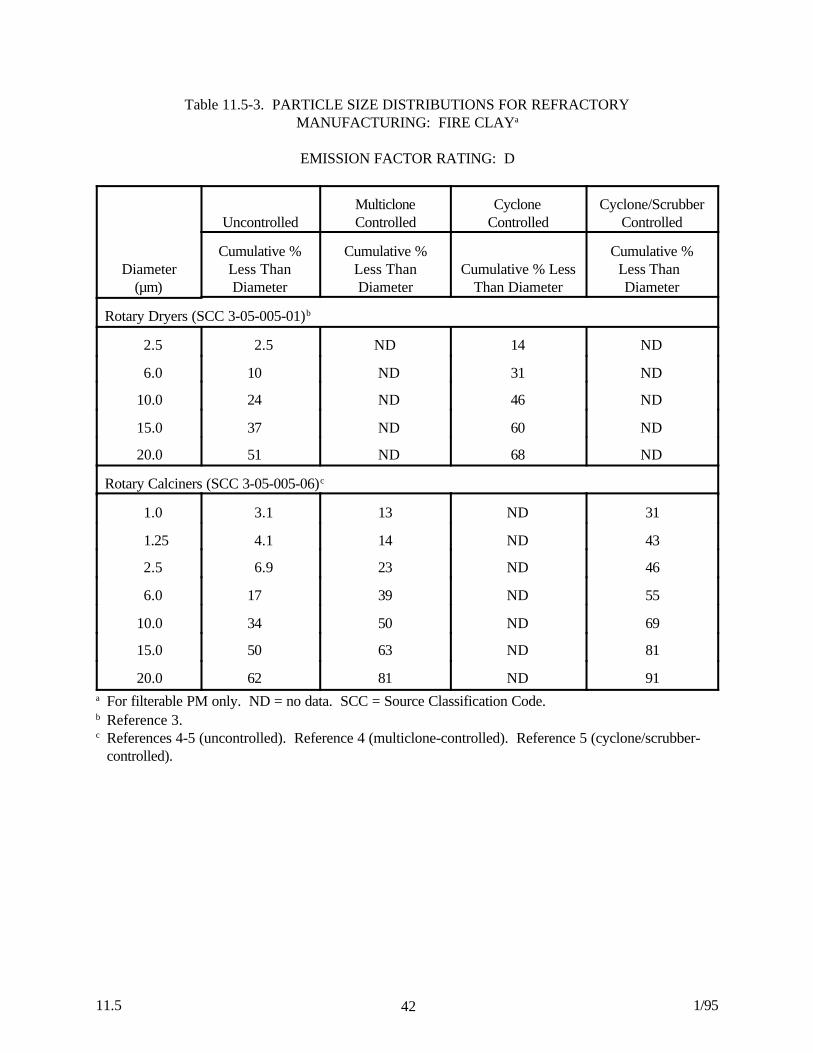
Pollutants emitted as a result of combustion in the calcining and kilning processes include sulfurdioxide (SO2), nitrogen oxides (NOx), carbon monoxide (CO), carbon dioxide (CO2), and volatile organiccompounds (VOC). The emission of SOx is also a function of the sulfur content of certain clays and theplaster added to refractory materials to induce brick setting. Fluoride emissions occur during the kilningprocess because of fluorides in the raw materials. Emission factors for filterable PM, PM-10, SO2, NOx,and CO2 emissions from rotary dryers and calciners processing fire clay are presented in Tables 11.5-1and 11.5-2. Particle size distributions for filterable particulate emissions from rotary dryers and calcinersprocessing fire clay are presented in Table 11.5-3.
Volatile organic compounds emitted from tar and pitch operations generally are controlled byincineration, when inorganic particulates are not significant. Based on the expected destruction of organicaerosols, a control efficiency in excess of 95 percent can be achieved using incinerators.
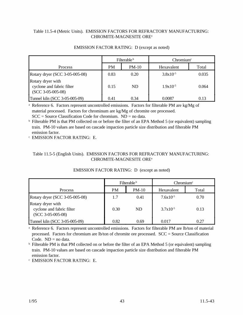
Chromium is used in several types of nonclay refractories, including chrome-magnesite, (chromite-magnesite), magnesia-chrome, and chrome-alumina. Chromium compounds are emitted from the orecrushing, grinding, material drying and storage, and brick firing and finishing processes used in producingthese types of refractories. Tables 11.5-4 and 11.5-5 present emission factors for emissions of filterablePM, filterable PM-10, hexavalent chromium, and total chromium from the drying and firing of chromite-magnesite ore. The emission factors are presented in units of kilograms of pollutant emitted permegagram of chromite ore processed (kg/Mg CrO3) (pounds per ton of chromite ore processed [lb/tonCrO3]). Particle size distributions for the drying and firing of chromite-magnesite ore are summarized inTable 11.5-6.
A number of elements in trace concentrations including aluminum, beryllium, calcium, chromium, iron,lead, mercury, magnesium, manganese, nickel, titanium, vanadium, and zinc also are emitted in traceamounts by the drying, calcining, and firing operations of all types of refractory materials. However, dataare inadequate to develop emission factors for these elements.
Emissions of PM from electric arc furnaces producing fused cast refractory material are controlledwith baghouses. The efficiency of the fabric filters often exceeds 99.5 percent. Emissions of PM fromthe ceramic fiber process also are controlled with fabric filters, at an efficiency similar to that found in thefused cast refractory process. To control blowchamber emissions, a fabric filter is used to remove small
1/95 11.5-3939
pieces of fine threads formed in the fiberization stage. The efficiency of fabric filters in similar controldevices exceeds 99 percent. Small particles of ceramic fiber are broken off
4011.5 1/95
or separated during the handling and forming of the fiber blankets in the curing oven. An oil is used in thisprocess, and higher molecular weight organics may be emitted. However, these emissions generally arecontrolled with a fabric filter followed by incineration, at an expected overall efficiency in excess of 95percent.
Table 11.5-1 (Metric Units). EMISSION FACTORS FOR REFRACTORYMANUFACTURING: FIRE CLAYa
EMISSION FACTOR RATING: D
Process SO2 NOx CO2
Filterable b
PM PM-10
Rotary dryerc (SCC 3-05-005-01)
ND ND 15 33 8.1
Rotary dryer with cyclone (SCC 3-05-005-01)
ND ND 15 5.6 2.6
Rotary dryer with cyclone and wet scrubberc
(SCC 3-05-005-01)ND ND
15 0.052 ND
Rotary calciner(SCC 3-05-005-06)
ND ND 300c 62d 14e
Rotary calciner with multiclone(SCC 3-05-005-06)
ND ND 300c 31f ND
Rotary calciner with multiclone and wet scrubber
(SCC 3-05-005-06)3.8d 0.87d 300c 0.15d 0.031e
a Factors represent uncontrolled emissions, unless noted. All emission factors in kg/Mg of raw materialfeed. SCC = Source Classification Code. ND = no data.
b Filterable PM is that PM collected on or before the filter of an EPA Method 5 (or equivalent) samplingtrain. PM-10 values are based on cascade impaction particle size distribution.
c Reference 3.d References 4-5.e Reference 4.f Reference 5.
1/95 11.5-4141
Table 11.5-2 (English Units). EMISSION FACTORS FOR REFRACTORY MANUFACTURING: FIRE CLAYa
EMISSION FACTOR RATING: D
Process SO2 NOx CO2
Filterable b
PM PM-10
Rotary dryerc
(SCC 3-05-005-01)ND ND 30 65 16
Rotary dryer with cyclonec
(SCC 3-05-005-01)ND ND 30 11 5.1
Rotary dryer with cyclone and wet scrubberc
(SCC 3-05-005-01)ND ND 30 0.11 ND
Rotary calciner (SCC 3-05-005-06)
ND ND 600c 120d 30e
Rotary calciner with multiclone (SCC 3-05-005-06)
ND ND 600c 61f ND
Rotary calciner with multiclone and wet scrubber (SCC 3-05-005-06)
7.6d 1.7d ND 0.30d 0.062e
a Factors represent uncontrolled emissions, unless noted. All emission factors in lb/ton of raw materialfeed. SCC = Source Classification Code. ND = no data.
b Filterable PM is that PM collected on or before the filter of an EPA Method 5 (or equivalent) samplingtrain. PM-10 values are based on cascade impaction particle size distribution.
c Reference 3.d References 4-5.e Reference 4.f Reference 5.
4211.5 1/95
Table 11.5-3. PARTICLE SIZE DISTRIBUTIONS FOR REFRACTORYMANUFACTURING: FIRE CLAYa
EMISSION FACTOR RATING: D
Diameter(µm)
UncontrolledMulticloneControlled
CycloneControlled
Cyclone/ScrubberControlled
Cumulative %Less ThanDiameter
Cumulative %Less ThanDiameter
Cumulative % LessThan Diameter
Cumulative %Less Than Diameter
Rotary Dryers (SCC 3-05-005-01)b
2.5 2.5 ND 14 ND
6.0 10 ND 31 ND
10.0 24 ND 46 ND
15.0 37 ND 60 ND
20.0 51 ND 68 ND
Rotary Calciners (SCC 3-05-005-06)c
1.0 3.1 13 ND 31
1.25 4.1 14 ND 43
2.5 6.9 23 ND 46
6.0 17 39 ND 55
10.0 34 50 ND 69
15.0 50 63 ND 81
20.0 62 81 ND 91a For filterable PM only. ND = no data. SCC = Source Classification Code.b Reference 3.c References 4-5 (uncontrolled). Reference 4 (multiclone-controlled). Reference 5 (cyclone/scrubber-
controlled).
1/95 11.5-4343
Table 11.5-4 (Metric Units). EMISSION FACTORS FOR REFRACTORY MANUFACTURING: CHROMITE-MAGNESITE OREa
EMISSION FACTOR RATING: D (except as noted)
Process
Filterable b Chromiumc
PM PM-10 Hexavalent Total
Rotary dryer (SCC 3-05-005-08) 0.83 0.20 3.8x10⁻⁵ 0.035
Rotary dryer with cyclone and fabric filter (SCC 3-05-005-08)
0.15 ND 1.9x10⁻⁵ 0.064
Tunnel kiln (SCC 3-05-005-09) 0.41 0.34 0.0087 0.13a Reference 6. Factors represent uncontrolled emissions. Factors for filterable PM are kg/Mg of
material processed. Factors for chrominum are kg/Mg of chromite ore processed. SCC = Source Classification Code for chromium. ND = no data.
b Filterable PM is that PM collected on or before the filter of an EPA Method 5 (or equivalent) samplingtrain. PM-10 values are based on cascade impaction particle size distribution and filterable PMemission factor.
c EMISSION FACTOR RATING: E.
Table 11.5-5 (English Units). EMISSION FACTORS FOR REFRACTORY MANUFACTURING: CHROMITE-MAGNESITE OREa
EMISSION FACTOR RATING: D (except as noted)
Process
Filterable b Chromiumc
PM PM-10 Hexavalent Total
Rotary dryer (SCC 3-05-005-08) 1.7 0.41 7.6x10⁻⁵ 0.70
Rotary dryer withcyclone and fabric filter (SCC 3-05-005-08)
0.30 ND 3.7x10⁻⁵ 0.13
Tunnel kiln (SCC 3-05-005-09) 0.82 0.69 0.017 0.27a Reference 6. Factors represent uncontrolled emissions. Factors for filterable PM are lb/ton of material
processed. Factors for chromium are lb/ton of chromite ore processed. SCC = Source ClassificationCode. ND = no data.
b Filterable PM is that PM collected on or before the filter of an EPA Method 5 (or equivalent) samplingtrain. PM-10 values are based on cascade impaction particle size distribution and filterable PMemission factor.
c EMISSION FACTOR RATING: E.
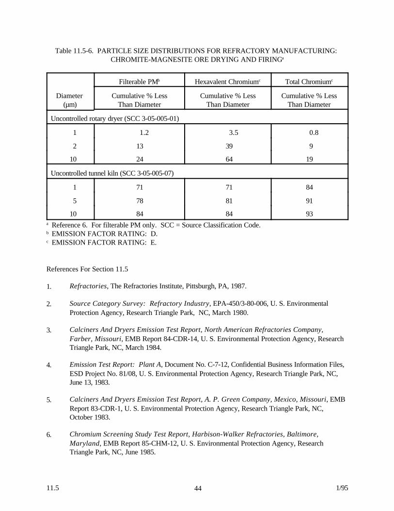
4411.5 1/95
Table 11.5-6. PARTICLE SIZE DISTRIBUTIONS FOR REFRACTORY MANUFACTURING: CHROMITE-MAGNESITE ORE DRYING AND FIRINGa
Diameter (µm)
Filterable PMb Hexavalent Chromiumc Total Chromiumc
Cumulative % LessThan Diameter
Cumulative % LessThan Diameter
Cumulative % LessThan Diameter
Uncontrolled rotary dryer (SCC 3-05-005-01)
1 1.2 3.5 0.8
2 13 39 9
10 24 64 19
Uncontrolled tunnel kiln (SCC 3-05-005-07)
1 71 71 84
5 78 81 91
10 84 84 93a Reference 6. For filterable PM only. SCC = Source Classification Code.b EMISSION FACTOR RATING: D.c EMISSION FACTOR RATING: E.
References For Section 11.5
1. Refractories, The Refractories Institute, Pittsburgh, PA, 1987.
2. Source Category Survey: Refractory Industry, EPA-450/3-80-006, U. S. EnvironmentalProtection Agency, Research Triangle Park, NC, March 1980.
3. Calciners And Dryers Emission Test Report, North American Refractories Company,Farber, Missouri, EMB Report 84-CDR-14, U. S. Environmental Protection Agency, ResearchTriangle Park, NC, March 1984.
4. Emission Test Report: Plant A, Document No. C-7-12, Confidential Business Information Files,ESD Project No. 81/08, U. S. Environmental Protection Agency, Research Triangle Park, NC,June 13, 1983.
5. Calciners And Dryers Emission Test Report, A. P. Green Company, Mexico, Missouri, EMBReport 83-CDR-1, U. S. Environmental Protection Agency, Research Triangle Park, NC,October 1983.
6. Chromium Screening Study Test Report, Harbison-Walker Refractories, Baltimore,Maryland, EMB Report 85-CHM-12, U. S. Environmental Protection Agency, ResearchTriangle Park, NC, June 1985.