emin sg fundaciones subestaciones transmision
TRANSCRIPT

®
December 2014
Phone: 573-682-5521 Email: [email protected] Web: hubbellpowersystems.com
Page 4B-1
Foundations & Installing Toolsfor Transmission & Substations
Catalog 4B December 2014
®
December 2014Page 4B-2
Phone: 573-682-5521 Email: [email protected] Web: hubbellpowersystems.com
The information in this manual is provided as a guide to assist you with your design and in writing your own specifications. Installation conditions, including soil and structure conditions, vary widely from location to location and from point to point on a site.
Independent engineering analysis and consulting state and local building codes and authorities should be conducted prior to any installation to ascertain and verify compli-ance to relevant rules, regulations and requirements.
Hubbell, Inc., shall not be responsible for, or liable to you and/or your customers for the adoption, revision, implementation, use or misuse of this information. Hubbell, Inc., takes great pride and has every confidence in its network of dealers/installing contrac-tors. Hubbell, Inc., does NOT warrant the work of its dealers/installing contractors in the installation of CHANCE® Civil Construction foundation support products.
DISCLAIMER
®
December 2014
Phone: 573-682-5521 Email: [email protected] Web: hubbellpowersystems.com
Page 4B-3
TABLE OF CONTENTS
SECTION DESCRIPTION PAGE
Square Shaft (SS) Products Introduction to Round and Square Shaft 4B-4 Square Shaft (SS) Product Ratings, Section Properties and Mechanical Strength 4B-5 - 6 11⁄2" Round Corner Square Shaft (SS5 Series) 4B-7 11⁄2" Round Corner Square Shaft (SS150 Series) 4B-8 13⁄4" Round Corner Square Shaft (SS175 Series) 4B-9 2" Round Corner Square Shaft (SS200 Series) 4B-10 21⁄4" Round Corner Square Shaft (SS225 Series) 4B-11 Notes: 11⁄4" to 21⁄4" Square Bar Products 4B-12 CHANCE® Helical Pulldown® Micropiles, Displacement Plates 4B-13 - 14
Round Shaft (RS) Products Catalog Numbering System for Helical Round Shaft Foundations 4B-15 Round Shaft (RS) Product Ratings, Section Properties and Mechanical Strength 4B-16 - 17 27⁄8" Round Shaft (RS2875.203 Series) 4B-18 27⁄8" Round Shaft (RS2875.276 Series) 4B-19 31⁄2" Round Shaft (RS3500.300 Series) 4B-20 41⁄2" Round Shaft (RS4500.337 Series) 4B-21 65⁄8" Round Shaft (RS6625.280 Series) 4B-22 85⁄8" Round Shaft (RS8625.250 Series) 4B-23 Notes: 27⁄8" to 85⁄8" OD Round (Pipe) Shaft Products 4B-24
Square Shaft & Round Shaft (SS/RS) Combinations 4B-25
Assemblies and Hardware CHANCE® Helical New Construction Pile and Rebar Caps 4B-26 Grillages 4B-27
Installation Tools 4B-28 - 37
SS
/RS
Co
mb
os
Inst
allin
g T
oo
lsH
ard
war
eR
oun
d S
haft
Sq
uare
Sha
ft
®
December 2014Page 4B-4
Phone: 573-682-5521 Email: [email protected] Web: hubbellpowersystems.com
Sq
uare Shaft
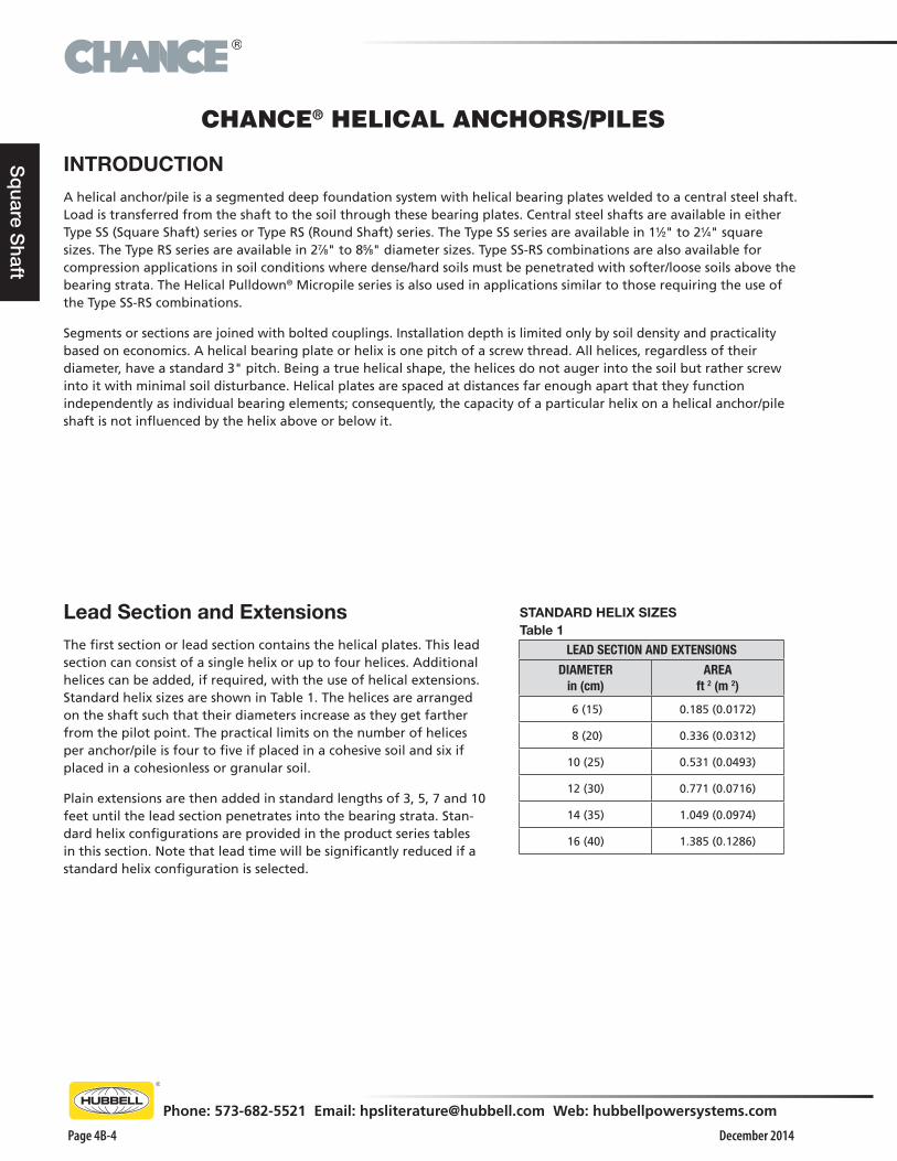
INTRODUCTIONA helical anchor/pile is a segmented deep foundation system with helical bearing plates welded to a central steel shaft. Load is transferred from the shaft to the soil through these bearing plates. Central steel shafts are available in either Type SS (Square Shaft) series or Type RS (Round Shaft) series. The Type SS series are available in 11⁄2" to 21⁄4" square sizes. The Type RS series are available in 27⁄8" to 85⁄8" diameter sizes. Type SS-RS combinations are also available for compression applications in soil conditions where dense/hard soils must be penetrated with softer/loose soils above the bearing strata. The Helical Pulldown® Micropile series is also used in applications similar to those requiring the use of the Type SS-RS combinations.
Segments or sections are joined with bolted couplings. Installation depth is limited only by soil density and practicality based on economics. A helical bearing plate or helix is one pitch of a screw thread. All helices, regardless of their diameter, have a standard 3" pitch. Being a true helical shape, the helices do not auger into the soil but rather screw into it with minimal soil disturbance. Helical plates are spaced at distances far enough apart that they function independently as individual bearing elements; consequently, the capacity of a particular helix on a helical anchor/pile shaft is not influenced by the helix above or below it.
Lead Section and ExtensionsThe first section or lead section contains the helical plates. This lead section can consist of a single helix or up to four helices. Additional helices can be added, if required, with the use of helical extensions. Standard helix sizes are shown in Table 1. The helices are arranged on the shaft such that their diameters increase as they get farther from the pilot point. The practical limits on the number of helices per anchor/pile is four to five if placed in a cohesive soil and six if placed in a cohesionless or granular soil.
Plain extensions are then added in standard lengths of 3, 5, 7 and 10 feet until the lead section penetrates into the bearing strata. Stan-dard helix configurations are provided in the product series tables in this section. Note that lead time will be significantly reduced if a standard helix configuration is selected.
CHANCE® HELICAL ANCHORS/PILES
STANDARD HELIX SIZES Table 1
LEAD SECTION AND EXTENSIONS
DIAMETER in (cm)
AREA ft 2 (m 2)
6 (15) 0.185 (0.0172)
8 (20) 0.336 (0.0312)
10 (25) 0.531 (0.0493)
12 (30) 0.771 (0.0716)
14 (35) 1.049 (0.0974)
16 (40) 1.385 (0.1286)
®
December 2014
Phone: 573-682-5521 Email: [email protected] Web: hubbellpowersystems.com
Page 4B-5
Sq
uare
Sha
ft
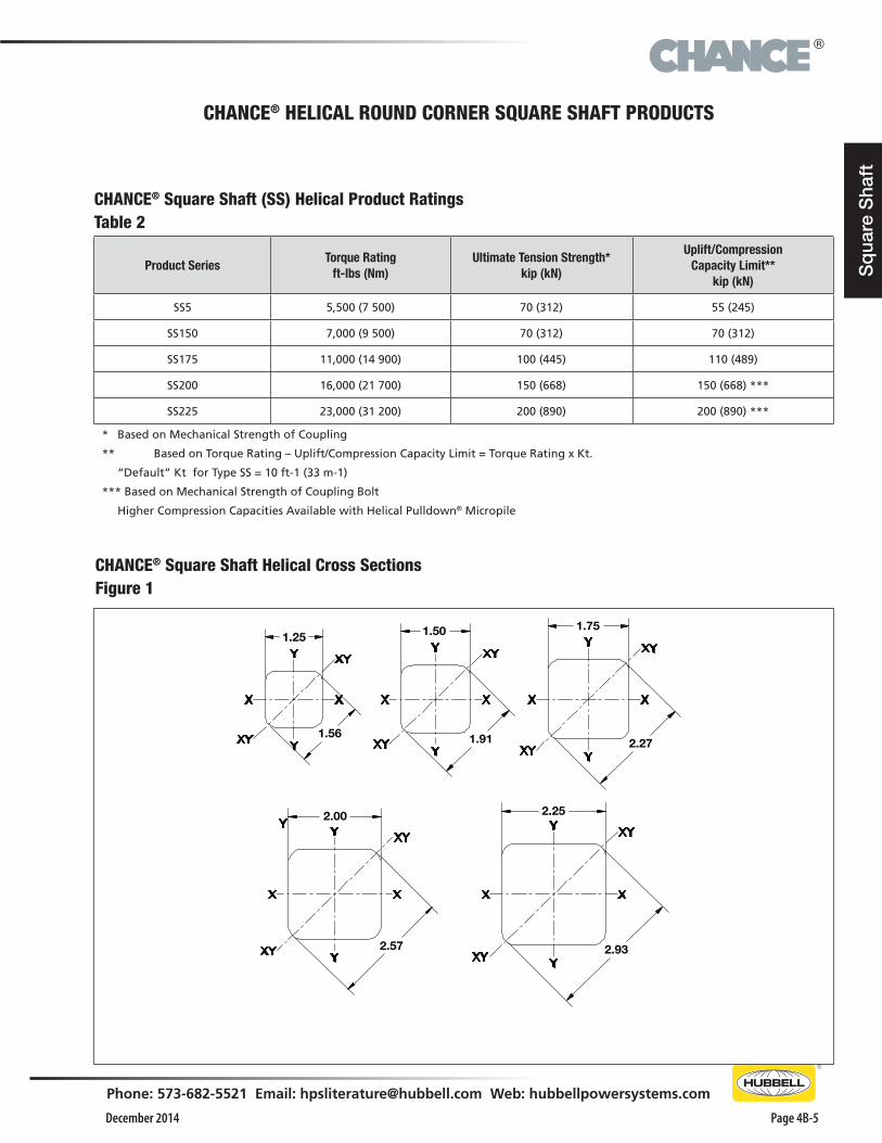
CHANCE® Square Shaft (SS) Helical Product RatingsTable 2
Product SeriesTorque Rating
ft-lbs (Nm)Ultimate Tension Strength*
kip (kN)
Uplift/Compression Capacity Limit**
kip (kN)
SS5 5,500 (7 500) 70 (312) 55 (245)
SS150 7,000 (9 500) 70 (312) 70 (312)
SS175 11,000 (14 900) 100 (445) 110 (489)
SS200 16,000 (21 700) 150 (668) 150 (668) ***
SS225 23,000 (31 200) 200 (890) 200 (890) ***
* Based on Mechanical Strength of Coupling
** Based on Torque Rating – Uplift/Compression Capacity Limit = Torque Rating x Kt.
“Default” Kt for Type SS = 10 ft-1 (33 m-1)
*** Based on Mechanical Strength of Coupling Bolt
Higher Compression Capacities Available with Helical Pulldown® Micropile
CHANCE® Square Shaft Helical Cross SectionsFigure 1
1.25 1.50
1.56 1.91 2.27
1.75
2.00 2.25
2.57 2.93
CHANCE® HELICAL ROUND CORNER SQUARE SHAFT PRODUCTS
®
December 2014Page 4B-6
Phone: 573-682-5521 Email: [email protected] Web: hubbellpowersystems.com
Sq
uare Shaft
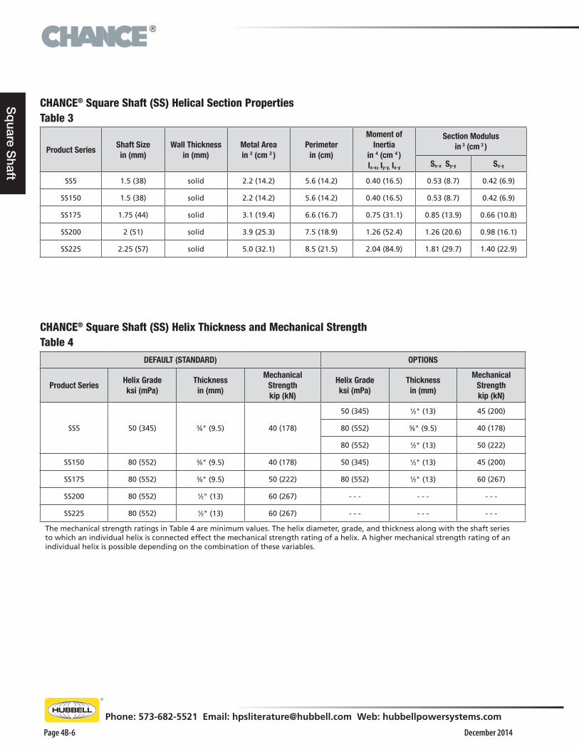
CHANCE® Square Shaft (SS) Helical Section PropertiesTable 3
Product SeriesShaft Sizein (mm)
Wall Thickness in (mm)
Metal Areain 2 (cm 2 )
Perimeterin (cm)
Moment of Inertia
in 4 (cm 4 )Ix-x, Iy-y, Ix-y
Section Modulusin 3 (cm 3 )
Sx-x Sy-y Sx-y
SS5 1.5 (38) solid 2.2 (14.2) 5.6 (14.2) 0.40 (16.5) 0.53 (8.7) 0.42 (6.9)
SS150 1.5 (38) solid 2.2 (14.2) 5.6 (14.2) 0.40 (16.5) 0.53 (8.7) 0.42 (6.9)
SS175 1.75 (44) solid 3.1 (19.4) 6.6 (16.7) 0.75 (31.1) 0.85 (13.9) 0.66 (10.8)
SS200 2 (51) solid 3.9 (25.3) 7.5 (18.9) 1.26 (52.4) 1.26 (20.6) 0.98 (16.1)
SS225 2.25 (57) solid 5.0 (32.1) 8.5 (21.5) 2.04 (84.9) 1.81 (29.7) 1.40 (22.9)
CHANCE® Square Shaft (SS) Helix Thickness and Mechanical StrengthTable 4
DEFAULT (STANDARD) OPTIONS
Product SeriesHelix Gradeksi (mPa)
Thicknessin (mm)
Mechanical Strengthkip (kN)
Helix Gradeksi (mPa)
Thicknessin (mm)
Mechanical Strengthkip (kN)
SS5 50 (345) 3⁄8" (9.5) 40 (178)
50 (345) 1⁄2" (13) 45 (200)
80 (552) 3⁄8" (9.5) 40 (178)
80 (552) 1⁄2" (13) 50 (222)
SS150 80 (552) 3⁄8" (9.5) 40 (178) 50 (345) 1⁄2" (13) 45 (200)
SS175 80 (552) 3⁄8" (9.5) 50 (222) 80 (552) 1⁄2" (13) 60 (267)
SS200 80 (552) 1⁄2" (13) 60 (267) - - - - - - - - -
SS225 80 (552) 1⁄2" (13) 60 (267) - - - - - - - - -
The mechanical strength ratings in Table 4 are minimum values. The helix diameter, grade, and thickness along with the shaft series to which an individual helix is connected effect the mechanical strength rating of a helix. A higher mechanical strength rating of an individual helix is possible depending on the combination of these variables.
®
December 2014
Phone: 573-682-5521 Email: [email protected] Web: hubbellpowersystems.com
Page 4B-7
Sq
uare
Sha
ft
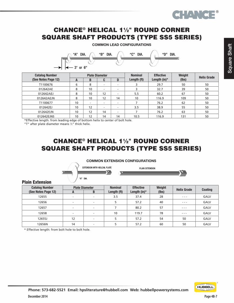
CHANCE® HELICAL 11⁄2" ROUND CORNER SQUARE SHAFT PRODUCTS (TYPE SS5 SERIES)
Catalog Number (See Notes Page 12)
Plate Diameter Nominal Length (ft)
Effective Length (in)*
Weight(lbs)
Helix GradeA B C D
T1100676 6 8 - - 3 29.7 50 50
012642AE 8 10 - - 3 32.7 39 50
012642AEJ 8 10 12 - 5.5 60.2 67 50
012642AEJN 8 10 12 14 10 116.9 109 50
T1100677 10 - - - 7 76.2 62 50
012642EJ 10 12 - - 3.5 38.9 55 50
012642EJN 10 12 14 - 7 76.2 63 50
012642EJNS 10 12 14 14 10.5 116.9 131 50*Effective length: from leading edge of bottom helix to center of bolt hole. “T” after plate diameter means 1⁄2" thick helix.
COMMON LEAD CONFIGURATIONS
CHANCE® HELICAL 11⁄2" ROUND CORNER SQUARE SHAFT PRODUCTS (TYPE SS5 SERIES)
Plain ExtensionCatalog Number
(See Notes Page 12)Plate Diameter Nominal
Length (ft)Effective
Length (in)*Weight
(lbs)Helix Grade Coating
A B12655 - - 3.5 37.4 28 - - - GALV
12656 - - 5 57.2 40 - - - GALV
12657 - - 7 80.2 57 - - - GALV
12658 - - 10 119.7 78 - - - GALV
12655J 12 - 5 57.2 54 50 GALV
12656N 14 - 5 57.2 60 50 GALV
* Effective length: from bolt hole to bolt hole.
COMMON EXTENSION CONFIGURATIONS

®
December 2014Page 4B-8
Phone: 573-682-5521 Email: [email protected] Web: hubbellpowersystems.com
Sq
uare Shaft
CHANCE® HELICAL 11⁄2" ROUND CORNER SQUARE SHAFT PRODUCTS (TYPE SS150 SERIES)
Catalog Number (See Notes Page 12)
Plate Diameter Nominal Length (ft)
Effective Length (in)*
Weight(lbs)
Helix GradeA B C
C1100388 - - - 3.5 37.4 27 - - -
C1100470 - - - 5 57.2 41 - - -
C1100389 - - - 7 80.2 54 - - -
C1100440 - - - 10 127.2 81 - - -
C1100471 14 - - 4 44.9 28 80
C1100454 14 14 - 7 80.2 93 80
C1100475 14 14 14 10 122.2 142 80
* Effective length: from bolt hole to bolt hole.
Catalog Number (See Notes Page 12)
Plate Diameter Nominal Length (ft)
Effective Length (in)*
Weight(lbs)
Helix GradeA B C D
T1100513 4 8 10 - 5 57.2 58 36
C1100385 8 10 - - 3 29.7 39 80
C1100386 8 10 12 - 5 60.2 70 80
T1100521 8 10 12 14 10 116.9 127 80
T1100631 10 12 14 - 7 76.2 96 80
C1100504 14 14 14 - 10 116.9 135 80
*Effective length: from leading edge of bottom helix to center of bolt hole.
COMMON LEAD CONFIGURATIONS
COMMON EXTENSION CONFIGURATIONS

®
December 2014
Phone: 573-682-5521 Email: [email protected] Web: hubbellpowersystems.com
Page 4B-9
Sq
uare
Sha
ft
CHANCE® HELICAL 13⁄4" ROUND CORNER SQUARE SHAFT PRODUCTS (TYPE SS175 SERIES)
CHANCE® HELICAL 13⁄4" ROUND CORNER SQUARE SHAFT PRODUCTS (TYPE SS175 SERIES)
Catalog Number (See Notes Page 12)
Plate Diameter Nominal Length (ft)
Effective Length (in)*
Weight(lbs)
Helix GradeA B C D
C1100227 8 10 - - 3.5 30.1 51 80
C1100235 8 10 12 - 5 57.8 82 80
C1100884 10 12 - - 5 57.8 80 80
C1100505 14 14 14 - 10 122.3 158 80
T1100730 14 14 - - 7 76.3 114 80*Effective length: from leading edge of bottom helix to center of bolt hole.
COMMON LEAD CONFIGURATIONS
COMMON EXTENSION CONFIGURATIONS
Catalog Number (See Notes Page 12)
Plate Diameter Nominal Length (ft)
Effective Length (in)*
Weight(lbs)
Helix GradeA B C
C1100136 - - - 3.5 36.8 35 - - -
C1100137 - - - 5 58.3 56 - - -
C1100138 - - - 7 79.8 76 - - -
C1100140 - - - 10 123.1 112 - - -
C1100472 14 - - 4 45.6 66 80
C1100450 14 14 - 7 79.8 116 80
C1100476 14 14 14 10 123.1 168 80
* Effective length: from bolt hole to bolt hole.
®
December 2014Page 4B-10
Phone: 573-682-5521 Email: [email protected] Web: hubbellpowersystems.com
Sq
uare Shaft
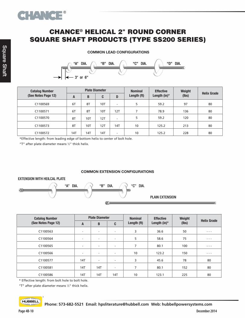
CHANCE® HELICAL 2" ROUND CORNER SQUARE SHAFT PRODUCTS (TYPE SS200 SERIES)
Catalog Number (See Notes Page 12)
Plate Diameter Nominal Length (ft)
Effective Length (in)*
Weight(lbs)
Helix GradeA B C
C1100563 - - - 3 36.6 50 - - -
C1100564 - - - 5 58.6 75 - - -
C1100565 - - - 7 80.1 100 - - -
C1100566 - - - 10 123.2 150 - - -
C1100577 14T - - 3 45.6 78 80
C1100581 14T 14T - 7 80.1 152 80
C1100586 14T 14T 14T 10 123.1 225 80
* Effective length: from bolt hole to bolt hole.
“T” after plate diameter means 1⁄2" thick helix.
Catalog Number (See Notes Page 12)
Plate Diameter Nominal Length (ft)
Effective Length (in)*
Weight(lbs)
Helix GradeA B C D
C1100569 6T 8T 10T - 5 59.2 97 80
C1100571 6T 8T 10T 12T 7 78.9 136 80
C1100570 8T 10T 12T - 5 59.2 120 80
C1100573 8T 10T 12T 14T 10 125.2 213 80
C1100572 14T 14T 14T - 10 125.2 228 80
*Effective length: from leading edge of bottom helix to center of bolt hole.
“T” after plate diameter means 1⁄2" thick helix.
COMMON LEAD CONFIGURATIONS
COMMON EXTENSION CONFIGURATIONS
®
December 2014
Phone: 573-682-5521 Email: [email protected] Web: hubbellpowersystems.com
Page 4B-11
Sq
uare
Sha
ft
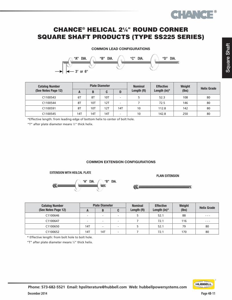
CHANCE® HELICAL 21⁄4" ROUND CORNER SQUARE SHAFT PRODUCTS (TYPE SS225 SERIES)
Catalog Number (See Notes Page 12)
Plate Diameter Nominal Length (ft)
Effective Length (in)*
Weight(lbs)
Helix GradeA B C
C1100646 - - - 5 52.1 88 - - -
C1100647 - - - 7 72.1 116 - - -
C1100650 14T - - 5 52.1 79 80
C1100652 14T 14T - 7 72.1 170 80
* Effective length: from bolt hole to bolt hole.
“T” after plate diameter means 1⁄2" thick helix.
Catalog Number (See Notes Page 12)
Plate Diameter Nominal Length (ft)
Effective Length (in)*
Weight(lbs)
Helix GradeA B C D
C1100543 6T 8T 10T - 5 52.3 108 80
C1100544 8T 10T 12T - 7 72.5 146 80
C1100591 8T 10T 12T 14T 10 112.8 142 80
C1100545 14T 14T 14T - 10 142.8 250 80
*Effective length: from leading edge of bottom helix to center of bolt hole.
“T” after plate diameter means 1⁄2" thick helix.
COMMON LEAD CONFIGURATIONS
COMMON EXTENSION CONFIGURATIONS
®
December 2014Page 4B-12
Phone: 573-682-5521 Email: [email protected] Web: hubbellpowersystems.com
Sq
uare Shaft
NOTES: 11⁄2" to 21⁄4" SQUARE BAR PRODUCTS1. Included Connection Hardware:
SS5 and SS150 11⁄2" Material: 3⁄4" diameter bolt per ASTM A325 Type 1 and nut.
SS175 13⁄4" Material: 7⁄8" diameter bolt per ASTM A193 Grade B7 and nut.
SS200 2" Material: 11⁄8" diameter bolt per ASTM A193 Grade B7and nut.
SS225 21⁄4" Material: 11⁄4" diameter bolt per ASTM A193 Grade B7 and nut.
2. The letter “T” after the helix diameter stands for 1⁄2" thick helix material.
3. All helices are spaced 3 times the diameter of the preceding helix unless otherwise specified by the customer.
4. The standard helix has a sharpened leading edge.
5. All products are hot dip galvanized per ASTM A153.

®
December 2014
Phone: 573-682-5521 Email: [email protected] Web: hubbellpowersystems.com
Page 4B-13
Sq
uare
Sha
ft
The Helical Pulldown® Micropile is a method used to form a grout column around the shaft of a standard helical anchor/pile. The installation process can employ grout only (see Figure 2) or grout in combination with either steel or PVC casing (see Figure 3).
To begin the process, a helical anchor/pile is placed into the soil by applying torque to the shaft. The helical shape of the bearing plates creates a significant downward force that keeps the foundation advancing into the soil. After the Lead Section with the helical plates penetrates the soil, a Lead Displacement Plate and Extension are placed onto the shaft. Resuming torque on the assembly advances the helical plates and pulls the displacement plate downward, forcing soil outward to create a cylindrical void around the shaft. From a reservoir at the surface, a flowable grout immediately fills this void surrounding the shaft. Additional extensions and displacement plates are added until the helical bearing plates reach the minimum depth required or competent load-bearing soil. This displacement pile system does not require removing spoils from the site.
Uncased Helical Pulldown® MicropileFigure 2
Cased Helical Pulldown® MicropileFigure 3
HELICAL PULLDOWN® MICROPILES
®
December 2014Page 4B-14
Phone: 573-682-5521 Email: [email protected] Web: hubbellpowersystems.com
Sq
uare Shaft
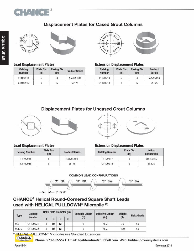
Displacement Plates for Cased Grout Columns
Lead Displacement PlatesCatalog Number
Plate Dia (in)
Casing Dia (in)
Product Series
T1100911 5 4 SS5/SS150
C1100912 7 6 SS175
Extension Displacement PlatesCatalog Number
Plate Dia (in)
Casing Dia (in)
Product Series
T1100913 5 4 SS5/SS150
C1100914 7 6 SS175
Lead Displacement Plates
Catalog NumberPlate Dia
(in)Product Series
T1100915 5 SS5/SS150
C1100916 5 SS175
Extension Displacement Plates
Catalog NumberPlate Dia
(in)Helical
Connection
T1100917 5 SS5/SS150
C1100918 5 SS175
CHANCE® Helical Round-Cornered Square Shaft Leadsused with HELICAL PULLDOWN® Micropile (1)
(1) HELICAL PULLDOWN® Micropiles use Standard Extensions.
TypeCatalogNumber
Helix Plate Diameter (in)
A B C D
Nominal Length(ft)
Effective Length(in)
Weight(lb)
Helix Grade
SS5 C1100921 8 10 12 - 7 76.2 79 50
SS175 C1100922 8 10 12 - 7 76.2 100 50
COMMON LEAD CONFIGURATIONS
Displacement Plates for Uncased Grout Columns
®
December 2014
Phone: 573-682-5521 Email: [email protected] Web: hubbellpowersystems.com
Page 4B-15
Ro
und
Sha
ft
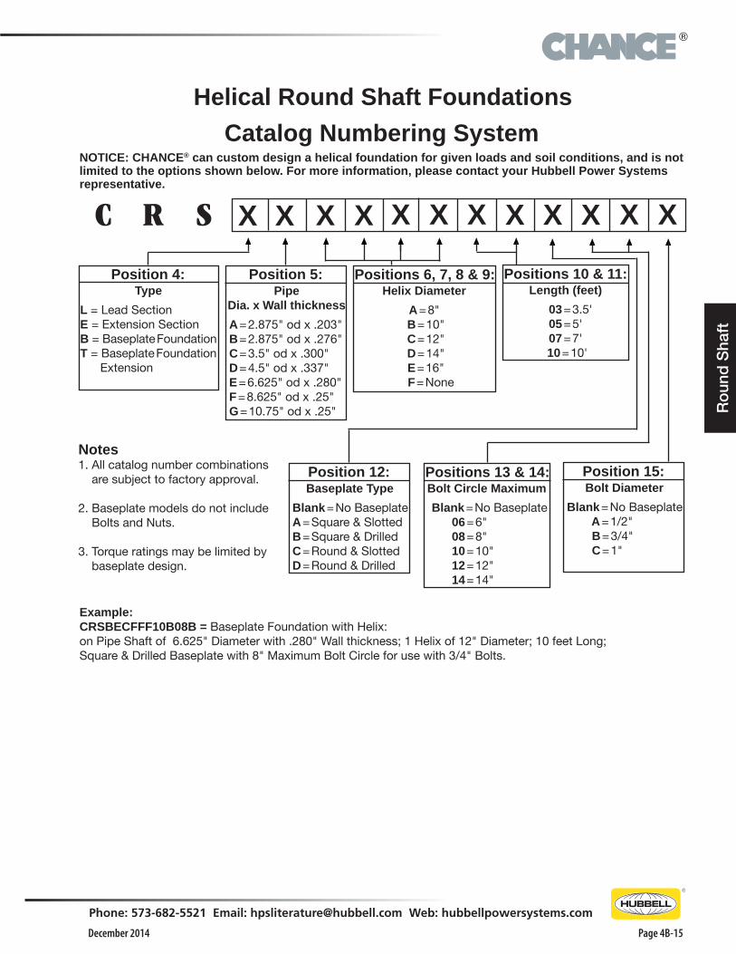
C R X X X X XXXX
Position 5:Pipe
Dia. x Wall thickness
A = 2.875" od x .203" B = 2.875" od x .276" C = 3.5" od x .300" D = 4.5" od x .337" E = 6.625" od x .280" F = 8.625" od x .25" G = 10.75" od x .25"
Position 4:Type
L = Lead SectionE = Extension SectionB = Baseplate FoundationT = Baseplate Foundation Extension
S X XXX
Helix Diameter
A = 8" B = 10" C = 12" D = 14" E = 16"
F = None
Positions 6, 7, 8 & 9:Length (feet)
03 = 3.5'05 = 5'07 = 7'
10 = 10'
Positions 10 & 11:
Position 15:Bolt Diameter
Blank = No Baseplate A = 1/2" B = 3/4" C = 1"
Bolt Circle Maximum
Blank = No Baseplate 06 = 6" 08 = 8" 10 = 10" 12 = 12" 14 = 14"
Positions 13 & 14:Position 12:Baseplate Type
Blank = No Baseplate A = Square & Slotted B = Square & Drilled C = Round & Slotted D = Round & Drilled
Notes 1. All catalog number combinations are subject to factory approval. 2. Baseplate models do not include Bolts and Nuts.
3. Torque ratings may be limited by baseplate design.
Catalog Numbering System
Example:CRSBECFFF10B08B = Baseplate Foundation with Helix:on Pipe Shaft of 6.625" Diameter with .280" Wall thickness; 1 Helix of 12" Diameter; 10 feet Long;Square & Drilled Baseplate with 8" Maximum Bolt Circle for use with 3/4" Bolts.
NOTICE: CHANCE® can custom design a helical foundation for given loads and soil conditions, and is not limited to the options shown below. For more information, please contact your Hubbell Power Systems representative.
Helical Round Shaft Foundations
®
December 2014Page 4B-16
Phone: 573-682-5521 Email: [email protected] Web: hubbellpowersystems.com
Ro
und S
haft
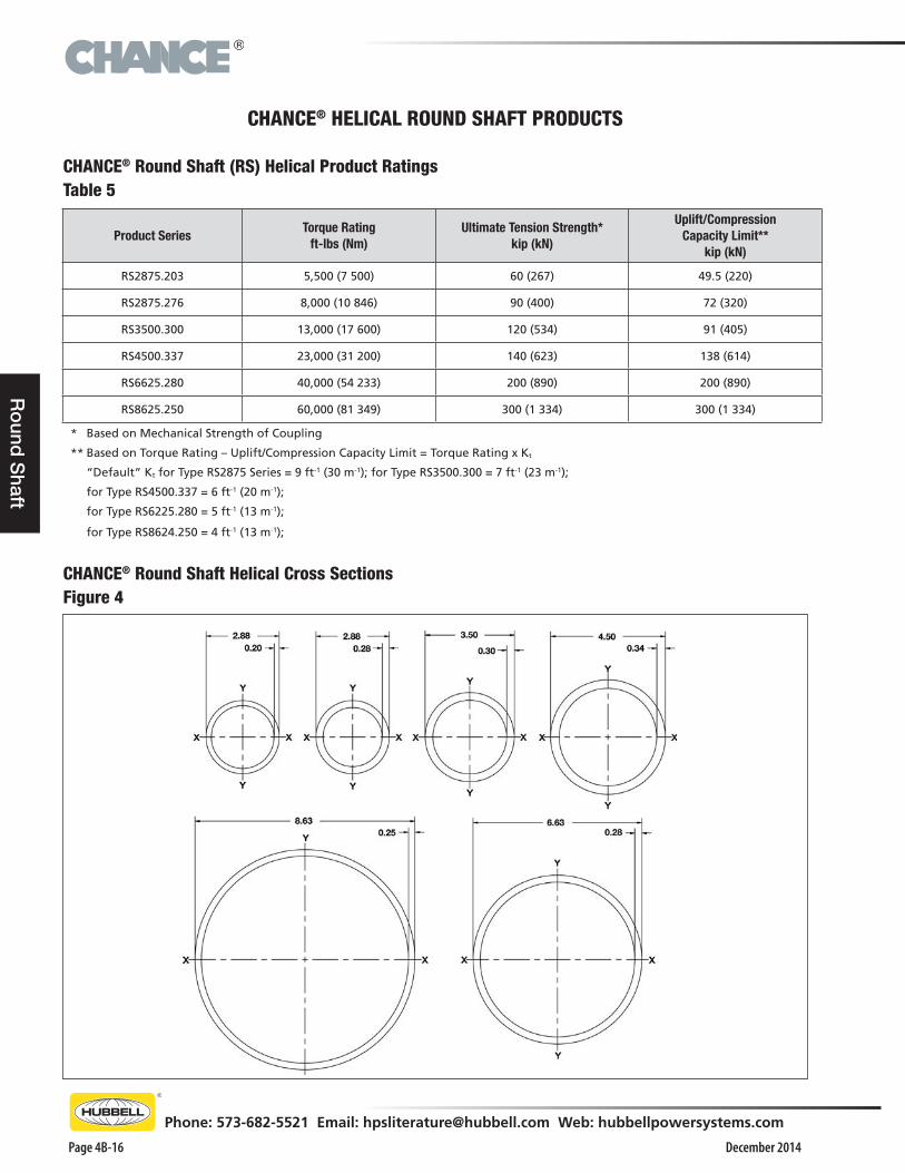
CHANCE® HELICAL ROUND SHAFT PRODUCTS
Product SeriesTorque Rating
ft-lbs (Nm)Ultimate Tension Strength*
kip (kN)
Uplift/Compression Capacity Limit**
kip (kN)
RS2875.203 5,500 (7 500) 60 (267) 49.5 (220)
RS2875.276 8,000 (10 846) 90 (400) 72 (320)
RS3500.300 13,000 (17 600) 120 (534) 91 (405)
RS4500.337 23,000 (31 200) 140 (623) 138 (614)
RS6625.280 40,000 (54 233) 200 (890) 200 (890)
RS8625.250 60,000 (81 349) 300 (1 334) 300 (1 334)
* Based on Mechanical Strength of Coupling
** Based on Torque Rating – Uplift/Compression Capacity Limit = Torque Rating x Kt
“Default” Kt for Type RS2875 Series = 9 ft-1 (30 m-1); for Type RS3500.300 = 7 ft-1 (23 m-1);
for Type RS4500.337 = 6 ft-1 (20 m-1);
for Type RS6225.280 = 5 ft-1 (13 m-1);
for Type RS8624.250 = 4 ft-1 (13 m-1);
CHANCE® Round Shaft Helical Cross SectionsFigure 4
CHANCE® Round Shaft (RS) Helical Product RatingsTable 5
®
December 2014
Phone: 573-682-5521 Email: [email protected] Web: hubbellpowersystems.com
Page 4B-17
Ro
und
Sha
ft
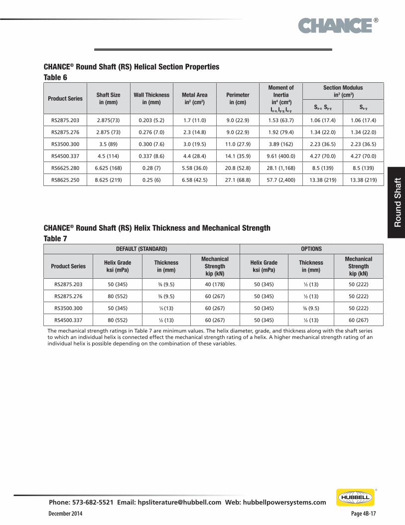
CHANCE® Round Shaft (RS) Helical Section PropertiesTable 6
Product SeriesShaft Sizein (mm)
Wall Thickness in (mm)
Metal Areain2 (cm2)
Perimeter in (cm)
Moment of Inertia
in4 (cm4)Ix-x, Iy-y, Ix-y
Section Modulus in3 (cm3)
Sx-x Sy-y Sx-y
RS2875.203 2.875(73) 0.203 (5.2) 1.7 (11.0) 9.0 (22.9) 1.53 (63.7) 1.06 (17.4) 1.06 (17.4)
RS2875.276 2.875 (73) 0.276 (7.0) 2.3 (14.8) 9.0 (22.9) 1.92 (79.4) 1.34 (22.0) 1.34 (22.0)
RS3500.300 3.5 (89) 0.300 (7.6) 3.0 (19.5) 11.0 (27.9) 3.89 (162) 2.23 (36.5) 2.23 (36.5)
RS4500.337 4.5 (114) 0.337 (8.6) 4.4 (28.4) 14.1 (35.9) 9.61 (400.0) 4.27 (70.0) 4.27 (70.0)
RS6625.280 6.625 (168) 0.28 (7) 5.58 (36.0) 20.8 (52.8) 28.1 (1,168) 8.5 (139) 8.5 (139)
RS8625.250 8.625 (219) 0.25 (6) 6.58 (42.5) 27.1 (68.8) 57.7 (2,400) 13.38 (219) 13.38 (219)
CHANCE® Round Shaft (RS) Helix Thickness and Mechanical StrengthTable 7
DEFAULT (STANDARD) OPTIONS
Product SeriesHelix Gradeksi (mPa)
Thicknessin (mm)
Mechanical Strengthkip (kN)
Helix Gradeksi (mPa)
Thicknessin (mm)
Mechanical Strengthkip (kN)
RS2875.203 50 (345) 3⁄8 (9.5) 40 (178) 50 (345) 1⁄2 (13) 50 (222)
RS2875.276 80 (552) 3⁄8 (9.5) 60 (267) 50 (345) 1⁄2 (13) 50 (222)
RS3500.300 50 (345) 1⁄2 (13) 60 (267) 50 (345) 3⁄8 (9.5) 50 (222)
RS4500.337 80 (552) 1⁄2 (13) 60 (267) 50 (345) 1⁄2 (13) 60 (267)
The mechanical strength ratings in Table 7 are minimum values. The helix diameter, grade, and thickness along with the shaft series to which an individual helix is connected effect the mechanical strength rating of a helix. A higher mechanical strength rating of an individual helix is possible depending on the combination of these variables.

®
December 2014Page 4B-18
Phone: 573-682-5521 Email: [email protected] Web: hubbellpowersystems.com
Ro
und S
haft
Catalog Number (See Notes Page 24)
Plate DiameterNominal
Length (ft)Effective
Length (in)*Weight
(lbs)Helix Grade
Helix Edge**
A B C D
CRSLAABFF05 8 10 - - 5 56.5 45 50 SLE
CRSLAABFF07 8 10 - - 7 78.3 57 50 SLE
CRSLAABCF05 8 10 12 5 56.5 53 50 SLE
CRSLABFFF05 10 - - - 5 56.5 40 50 SLE
CRSLABFFF07 10 - - - 7 76.3 48 50 SLE
CRSLABCFF05 10 12 - - 5 56.5 53 50 SLE
CRSLABCFF07 10 12 - - 7 76.3 60 50 SLE
CRSLABCDF07 10 12 14 - 7 76.3 78 50 SLE
CRSLABCDF10 10 12 14 - 10 188.3 122 50 SLE
CRSLACFFF05 12 - - - 5 56.5 46 50 SLE
CRSLACFFF07 12 - - - 7 76.3 54 50 SLE
CRSLADFFF07 14 - - - 7 76.3 57 50 SLE
CRSLADFFF10 14 - - - 10 118.3 100 50 SLE
*Effective length: from leading edge of bottom helix to center of bolt hole.
Catalog Number (See Notes Page 24)
Plate DiameterNominal
Length (ft)Effective
Length (in)*Weight
(lbs)Helix Grade
Helix Edge**
A B C
CRSEAFFFF03 - - - 3.5 36.0 19 - - - - - -
CRSEAFFFF05 - - - 5 57.0 32 - - - - - -
CRSEAFFFF07 - - - 7’ 78.3 42 - - - - - -
CRSEAFFFF10 - - - 10 120 64 - - - - - -
CRSEADDFF07 14 14 - 7 78.0 75 50 SLE
CRSEADFFF05 14 - - 5 57.0 70 50 SLE
* Effective length: from bolt hole to bolt hole.
COMMON EXTENSION CONFIGURATIONS
CHANCE® HELICAL 27⁄8" DIAMETER ROUND SHAFT PRODUCTS (TYPE RS2875.203 SERIES)
COMMON LEAD CONFIGURATIONS
**SLE = Sharpened Leading Edge
**SLE = Sharpened Leading Edge
®
December 2014
Phone: 573-682-5521 Email: [email protected] Web: hubbellpowersystems.com
Page 4B-19
Ro
und
Sha
ft
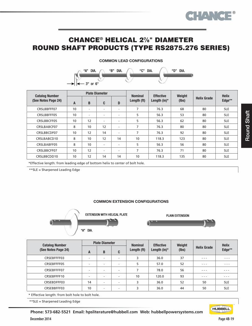
Catalog Number(See Notes Page 24)
Plate DiameterNominal
Length (ft)Effective
Length (in)*Weight
(lbs)Helix Grade
Helix Edge**
A B C D
CRSLBBFFF07 10 - - - 7 76.3 68 80 SLE
CRSLBBFFF05 10 - - - 5 56.3 53 80 SLE
CRSLBBCFF05 10 12 - - 5 56.3 62 80 SLE
CRSLBABCF07 8 10 12 - 7 76.3 80 80 SLE
CRSLBBCDF07 10 12 14 - 7 76.3 92 80 SLE
CRSLBABCD10 8 10 12 14 10 118.3 123 80 SLE
CRSLBABFF05 8 10 - - 5 56.3 56 80 SLE
CRSLBBCFF07 10 12 - - 7 76.3 71 80 SLE
CRSLBBCDD10 10 12 14 14 10 118.3 135 80 SLE
*Effective length: from leading edge of bottom helix to center of bolt hole.
Catalog Number(See Notes Page 24)
Plate DiameterNominal
Length (ft)Effective
Length (in)*Weight
(lbs)Helix Grade
Helix Edge**
A B C
CRSEBFFFF03 - - - 3 36.0 37 - - - - - -
CRSEBFFFF05 - - - 5 57.0 52 - - - - - -
CRSEBFFFF07 - - - 7 78.0 56 - - - - - -
CRSEBFFFF10 - - - 10 120.0 93 - - - - - -
CRSEBDFFF03 14 - - 3 36.0 52 50 SLE
CRSEBBFFF03 10 - - 3 36.0 44 50 SLE
* Effective length: from bolt hole to bolt hole.
COMMON EXTENSION CONFIGURATIONS
CHANCE® HELICAL 27⁄8" DIAMETER ROUND SHAFT PRODUCTS (TYPE RS2875.276 SERIES)
COMMON LEAD CONFIGURATIONS
**SLE = Sharpened Leading Edge
**SLE = Sharpened Leading Edge
®
December 2014Page 4B-20
Phone: 573-682-5521 Email: [email protected] Web: hubbellpowersystems.com
Ro
und S
haft
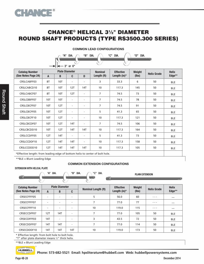
Catalog Number (See Notes Page 24)
Plate Diameter Nominal Length (ft)
Effective Length (in)*
Weight(lbs)
Helix Grade Helix Edge**A B C D
CRSLCABFF03 8T 10T - - 3 33.3 6 50 BLE
CRSLCABCD10 8T 10T 12T 14T 10 117.3 145 50 BLE
CRSLCABCF07 8T 10T 12T - 7 74.5 73 50 BLE
CRSLCBBFF07 10T 10T - - 7 74.5 78 50 BLE
CRSLCBCFF07 10T 12T - - 7 74.5 91 50 BLE
CRSLCBCFF05 10T 12T - - 5 41.3 65 50 BLE
CRSLCBCFF10 10T 12T - - 10 117.3 121 50 BLE
CRSLCBCDF07 10T 12T 14T - 7 74.5 106 50 BLE
CRSLCBCDD10 10T 12T 14T 14T 10 117.3 164 50 BLE
CRSLCCDFF05 12T 14T - - 5 41.3 73 50 BLE
CRSLCCDDF10 12T 14T 14T - 10 117.3 158 50 BLE
CRSLCCDDD10 12T 14T 14T 14T 10 117.3 105 50 BLE
*Effective length: from leading edge of bottom helix to center of bolt hole.
Catalog Number (See Notes Page 24)
Plate DiameterNominal Length (ft)
Effective Length (in)*
Weight(lbs)
Helix Grade Helix Edge**A B C
CRSECFFFF05 - - - 5 56.0 60 - - - —
CRSECFFFF07 - - - 7 77.0 77 - - - —
CRSECFFFF10 - - - 10 119.0 115 - - - —
CRSECCDFF07 12T 14T - 7 77.0 105 50 BLE
CRSECDFFF03 14T - - 3 43.5 72 50 BLE
CRSECDDFF07 14T 14T - 7 77.0 114 50 BLE
CRSECDDDF10 14T 14T 14T 10 119.0 173 50 BLE
* Effective length: from bolt hole to bolt hole. “T” after plate diameter means 1⁄2" thick helix.
COMMON EXTENSION CONFIGURATIONS
CHANCE® HELICAL 31⁄2" DIAMETER ROUND SHAFT PRODUCTS (TYPE RS3500.300 SERIES)
COMMON LEAD CONFIGURATIONS
**BLE = Blunt Leading Edge
**BLE = Blunt Leading Edge
®
December 2014
Phone: 573-682-5521 Email: [email protected] Web: hubbellpowersystems.com
Page 4B-21
Ro
und
Sha
ft
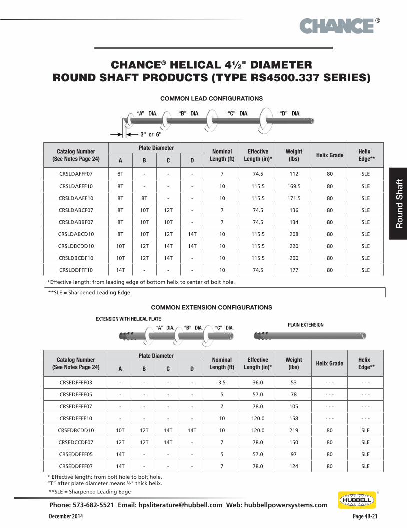
Catalog Number(See Notes Page 24)
Plate DiameterNominal
Length (ft)Effective
Length (in)*Weight
(lbs)Helix Grade
Helix Edge**A B C D
CRSLDAFFF07 8T - - - 7 74.5 112 80 SLE
CRSLDAFFF10 8T - - - 10 115.5 169.5 80 SLE
CRSLDAAFF10 8T 8T - - 10 115.5 171.5 80 SLE
CRSLDABCF07 8T 10T 12T - 7 74.5 136 80 SLE
CRSLDABBF07 8T 10T 10T - 7 74.5 134 80 SLE
CRSLDABCD10 8T 10T 12T 14T 10 115.5 208 80 SLE
CRSLDBCDD10 10T 12T 14T 14T 10 115.5 220 80 SLE
CRSLDBCDF10 10T 12T 14T - 10 115.5 200 80 SLE
CRSLDDFFF10 14T - - - 10 74.5 177 80 SLE
*Effective length: from leading edge of bottom helix to center of bolt hole.
COMMON EXTENSION CONFIGURATIONS
CHANCE® HELICAL 41⁄2" DIAMETER ROUND SHAFT PRODUCTS (TYPE RS4500.337 SERIES)
COMMON LEAD CONFIGURATIONS
Catalog Number(See Notes Page 24)
Plate DiameterNominal
Length (ft)Effective
Length (in)*Weight
(lbs)Helix Grade
Helix Edge**A B C D
CRSEDFFFF03 - - - - 3.5 36.0 53 - - - - - -
CRSEDFFFF05 - - - - 5 57.0 78 - - - - - -
CRSEDFFFF07 - - - - 7 78.0 105 - - - - - -
CRSEDFFFF10 - - - - 10 120.0 158 - - - - - -
CRSEDBCDD10 10T 12T 14T 14T 10 120.0 219 80 SLE
CRSEDCCDF07 12T 12T 14T - 7 78.0 150 80 SLE
CRSEDDFFF05 14T - - - 5 57.0 97 80 SLE
CRSEDDFFF07 14T - - - 7 78.0 124 80 SLE
* Effective length: from bolt hole to bolt hole. “T” after plate diameter means 1⁄2" thick helix.
**SLE = Sharpened Leading Edge
**SLE = Sharpened Leading Edge
®
December 2014Page 4B-22
Phone: 573-682-5521 Email: [email protected] Web: hubbellpowersystems.com
Ro
und S
haft
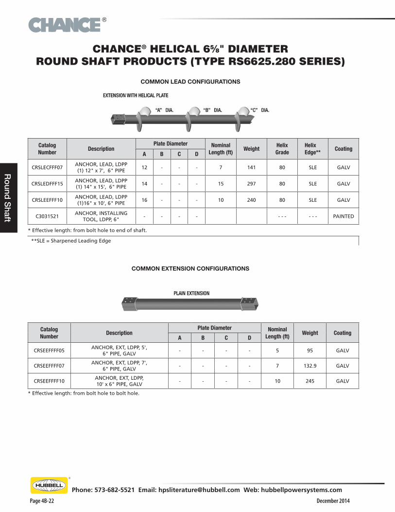
Catalog Number
DescriptionPlate Diameter Nominal
Length (ft)Weight
Helix Grade
Helix Edge**
CoatingA B C D
CRSLECFFF07ANCHOR, LEAD, LDPP (1) 12" x 7', 6" PIPE
12 - - - 7 141 80 SLE GALV
CRSLEDFFF15ANCHOR, LEAD, LDPP (1) 14" x 15', 6" PIPE
14 - - - 15 297 80 SLE GALV
CRSLEEFFF10ANCHOR, LEAD, LDPP (1)16" x 10', 6" PIPE
16 - - - 10 240 80 SLE GALV
C3031521ANCHOR, INSTALLING
TOOL, LDPP, 6"- - - - - - - - - - PAINTED
* Effective length: from bolt hole to end of shaft.
COMMON EXTENSION CONFIGURATIONS
CHANCE® HELICAL 65⁄8" DIAMETER ROUND SHAFT PRODUCTS (TYPE RS6625.280 SERIES)
COMMON LEAD CONFIGURATIONS
Catalog Number
DescriptionPlate Diameter Nominal
Length (ft)Weight Coating
A B C D
CRSEEFFFF05ANCHOR, EXT, LDPP, 5',
6" PIPE, GALV- - - - 5 95 GALV
CRSEEFFFF07ANCHOR, EXT, LDPP, 7',
6" PIPE, GALV- - - - 7 132.9 GALV
CRSEEFFFF10ANCHOR, EXT, LDPP, 10' x 6" PIPE, GALV
- - - - 10 245 GALV
* Effective length: from bolt hole to bolt hole.
**SLE = Sharpened Leading Edge
®
December 2014
Phone: 573-682-5521 Email: [email protected] Web: hubbellpowersystems.com
Page 4B-23
Ro
und
Sha
ft
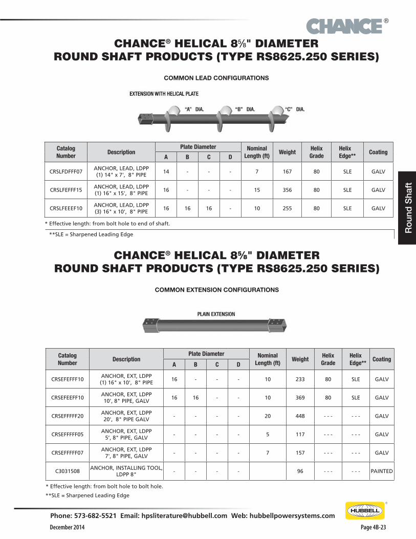
Catalog Number
DescriptionPlate Diameter Nominal
Length (ft)Weight
Helix Grade
Helix Edge**
CoatingA B C D
CRSLFDFFF07ANCHOR, LEAD, LDPP (1) 14" x 7', 8" PIPE
14 - - - 7 167 80 SLE GALV
CRSLFEFFF15ANCHOR, LEAD, LDPP (1) 16" x 15', 8" PIPE
16 - - - 15 356 80 SLE GALV
CRSLFEEEF10ANCHOR, LEAD, LDPP (3) 16" x 10', 8" PIPE
16 16 16 - 10 255 80 SLE GALV
* Effective length: from bolt hole to end of shaft.
CHANCE® HELICAL 85⁄8" DIAMETER ROUND SHAFT PRODUCTS (TYPE RS8625.250 SERIES)
COMMON LEAD CONFIGURATIONS
COMMON EXTENSION CONFIGURATIONS
Catalog Number
DescriptionPlate Diameter Nominal
Length (ft)Weight
Helix Grade
Helix Edge**
CoatingA B C D
CRSEFEFFF10ANCHOR, EXT, LDPP (1) 16" x 10', 8" PIPE
16 - - - 10 233 80 SLE GALV
CRSEFEEFF10ANCHOR, EXT, LDPP 10', 8" PIPE, GALV
16 16 - - 10 369 80 SLE GALV
CRSEFFFFF20ANCHOR, EXT, LDPP 20', 8" PIPE GALV
- - - - 20 448 - - - - - - GALV
CRSEFFFFF05ANCHOR, EXT, LDPP
5’, 8" PIPE, GALV- - - - 5 117 - - - - - - GALV
CRSEFFFFF07ANCHOR, EXT, LDPP
7', 8" PIPE, GALV- - - - 7 157 - - - - - - GALV
C3031508ANCHOR, INSTALLING TOOL,
LDPP 8"- - - - 96 - - - - - - PAINTED
* Effective length: from bolt hole to bolt hole.
CHANCE® HELICAL 85⁄8" DIAMETER ROUND SHAFT PRODUCTS (TYPE RS8625.250 SERIES)
**SLE = Sharpened Leading Edge
**SLE = Sharpened Leading Edge

®
December 2014Page 4B-24
Phone: 573-682-5521 Email: [email protected] Web: hubbellpowersystems.com
Ro
und S
haft
NOTES: 27⁄8" to 85⁄8" OD ROUND (PIPE) SHAFT PRODUCTS1. Included Connection Hardware:
RS2875.203 27⁄8" Diameter Material: (2) 3⁄4" x 41⁄4" bolt per SAE J429 Grade 5 and nuts.
RS2875.276 27⁄8" Diameter Material: (2) 3⁄4" x 41⁄4" bolt per SAE J429 Grade 5 and nuts.
RS3500.300 31⁄2" Diameter Material: (3) 3⁄4" x 53⁄4" bolt per SAE J429 Grade 5 and nuts.
RS4500.337 41⁄2" Diameter Material: (2) 1" x 51⁄2" bolt per SAE J429 Grade 8 and nuts.
RS6625.280 6" Diameter Material: (4) 1" x 8" Threaded Stud and nuts.
RS8625.250 8" Diameter Material: (4) 11⁄4" x 101⁄2" Threaded Stud and nuts.
2. The letter “T” after the helix diameter stands for 1⁄2" thick helix material.
3. All helices are spaced 3 times the diameter of the preceding helix unless otherwise specified by the Customer.
4. All products are Hot Dip Galvanize per ASTM A153.
®
December 2014
Phone: 573-682-5521 Email: [email protected] Web: hubbellpowersystems.com
Page 4B-25
SS
/RS
Co
mb
os
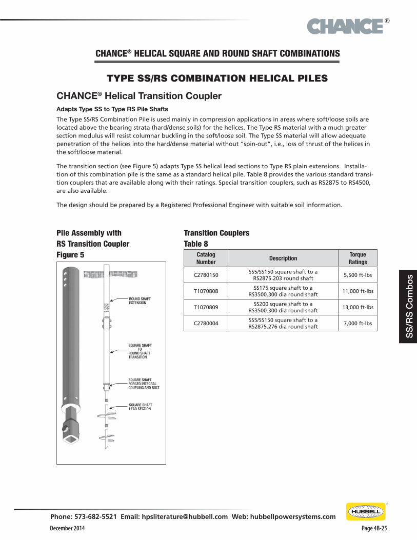
TYPE SS/RS COMBINATION HELICAL PILES
Transition CouplersTable 8
Catalog Number
DescriptionTorque Ratings
C2780150SS5/SS150 square shaft to a
RS2875.203 round shaft5,500 ft-lbs
T1070808SS175 square shaft to a
RS3500.300 dia round shaft11,000 ft-lbs
T1070809SS200 square shaft to a
RS3500.300 dia round shaft13,000 ft-lbs
C2780004SS5/SS150 square shaft to a RS2875.276 dia round shaft
7,000 ft-lbs
CHANCE® Helical Transition CouplerAdapts Type SS to Type RS Pile Shafts
The Type SS/RS Combination Pile is used mainly in compression applications in areas where soft/loose soils are located above the bearing strata (hard/dense soils) for the helices. The Type RS material with a much greater section modulus will resist columnar buckling in the soft/loose soil. The Type SS material will allow adequate penetration of the helices into the hard/dense material without “spin-out”, i.e., loss of thrust of the helices in the soft/loose material.
The transition section (see Figure 5) adapts Type SS helical lead sections to Type RS plain extensions. Installa-tion of this combination pile is the same as a standard helical pile. Table 8 provides the various standard transi-tion couplers that are available along with their ratings. Special transition couplers, such as RS2875 to RS4500, are also available.
The design should be prepared by a Registered Professional Engineer with suitable soil information.
Pile Assembly with RS Transition CouplerFigure 5
CHANCE® HELICAL SQUARE AND ROUND SHAFT COMBINATIONS
ROUND SHAFTEXTENSION
SQUARE SHAFT TOROUND SHAFTTRANSITION
SQUARE SHAFTFORGED INTEGRALCOUPLING AND BOLT
SQUARE SHAFTLEAD SECTION
®
December 2014Page 4B-26
Phone: 573-682-5521 Email: [email protected] Web: hubbellpowersystems.com
Hard
ware
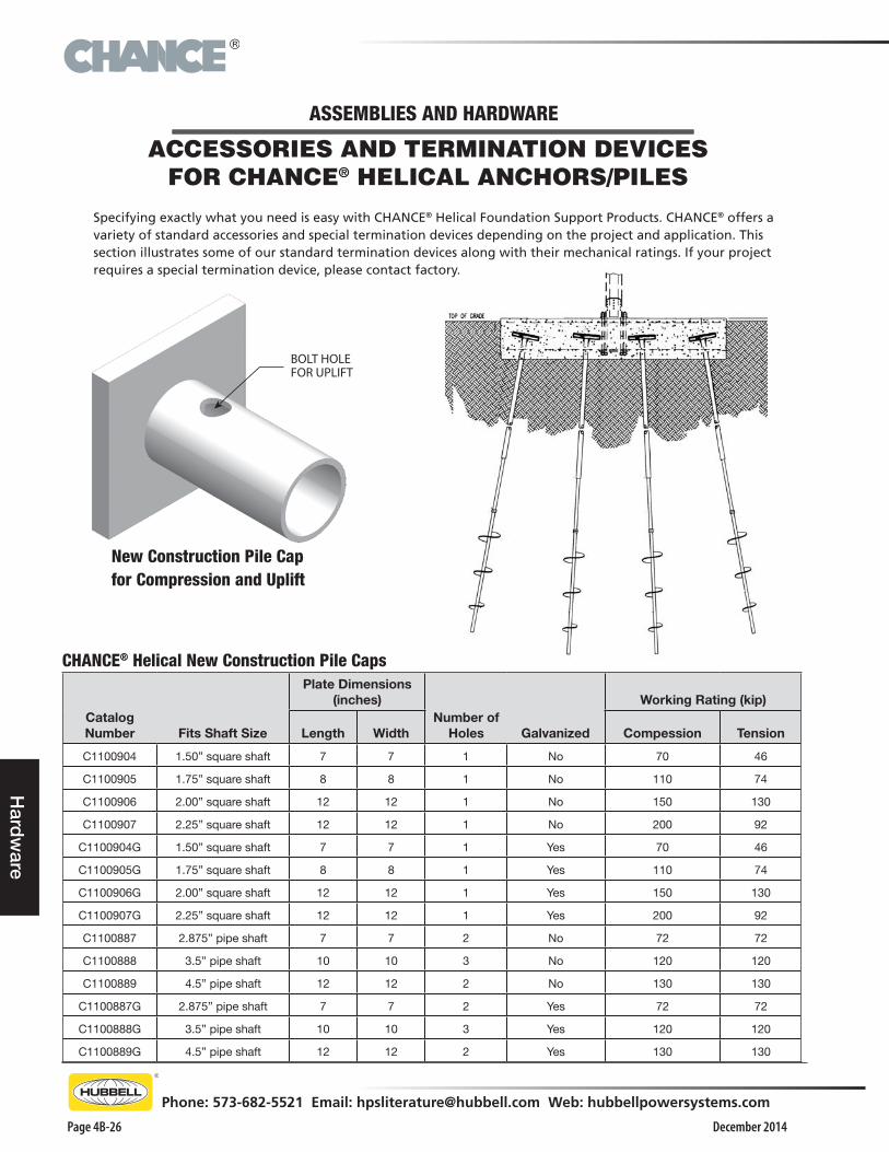
CHANCE® Helical New Construction Pile Caps
Catalog Number Fits Shaft Size
Plate Dimensions (inches)
Number of Holes Galvanized
Working Rating (kip)
Length Width Compession Tension
C1100904 1.50” square shaft 7 7 1 No 70 46
C1100905 1.75” square shaft 8 8 1 No 110 74
C1100906 2.00” square shaft 12 12 1 No 150 130
C1100907 2.25” square shaft 12 12 1 No 200 92
C1100904G 1.50” square shaft 7 7 1 Yes 70 46
C1100905G 1.75” square shaft 8 8 1 Yes 110 74
C1100906G 2.00” square shaft 12 12 1 Yes 150 130
C1100907G 2.25” square shaft 12 12 1 Yes 200 92
C1100887 2.875” pipe shaft 7 7 2 No 72 72
C1100888 3.5” pipe shaft 10 10 3 No 120 120
C1100889 4.5” pipe shaft 12 12 2 No 130 130
C1100887G 2.875” pipe shaft 7 7 2 Yes 72 72
C1100888G 3.5” pipe shaft 10 10 3 Yes 120 120
C1100889G 4.5” pipe shaft 12 12 2 Yes 130 130
ACCESSORIES AND TERMINATION DEVICES FOR CHANCE® HELICAL ANCHORS/PILES
Specifying exactly what you need is easy with CHANCE® Helical Foundation Support Products. CHANCE® offers a variety of standard accessories and special termination devices depending on the project and application. This section illustrates some of our standard termination devices along with their mechanical ratings. If your project requires a special termination device, please contact factory.
BOLT HOLEFOR UPLIFT
New Construction Pile Capfor Compression and Uplift
ASSEMBLIES AND HARDWARE
®
December 2014
Phone: 573-682-5521 Email: [email protected] Web: hubbellpowersystems.com
Page 4B-27
Har
dw
are
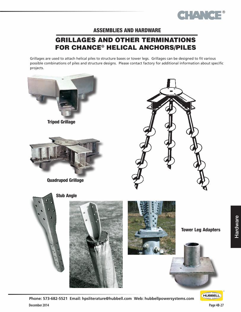
Quadrupod Grillage
Stub Angle
Tripod Grillage
Tower Leg Adapters
GRILLAGES AND OTHER TERMINATIONS FOR CHANCE® HELICAL ANCHORS/PILES
Grillages are used to attach helical piles to structure bases or tower legs. Grillages can be designed to fit various possible combinations of piles and structure designs. Please contact factory for additional information about specific projects.
ASSEMBLIES AND HARDWARE
®
December 2014Page 4B-28
Phone: 573-682-5521 Email: [email protected] Web: hubbellpowersystems.com
Installing To
ols
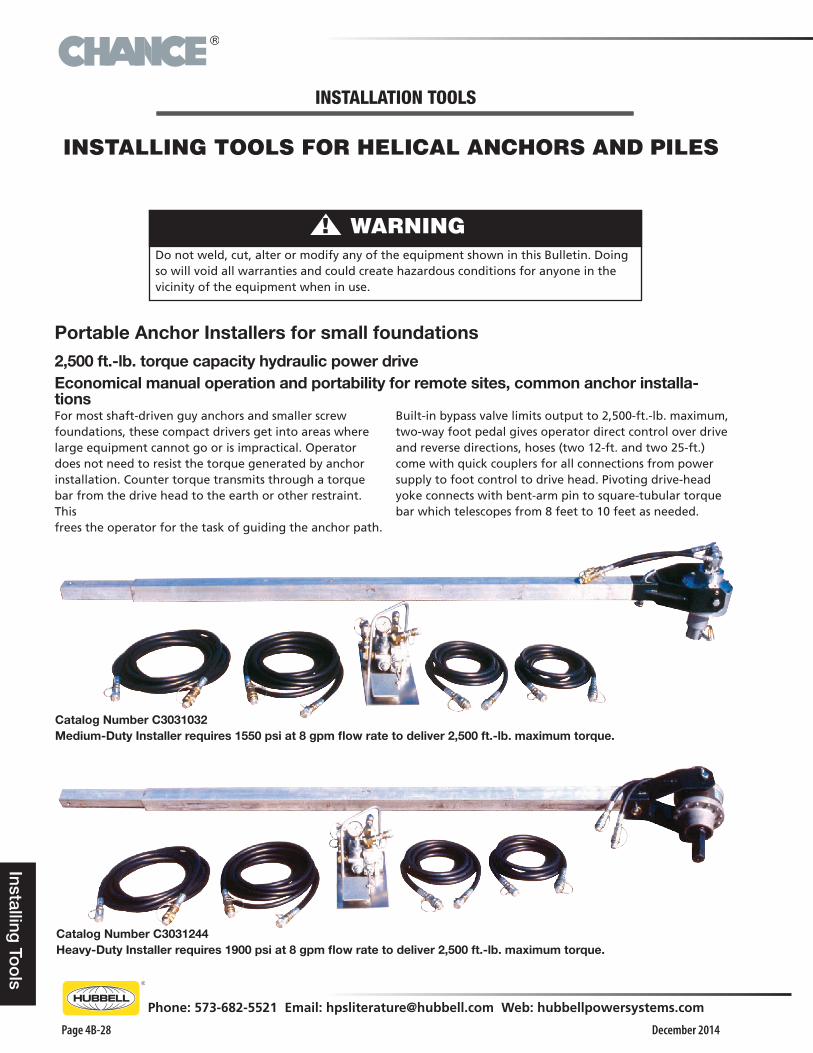
INSTALLING TOOLS FOR HELICAL ANCHORS AND PILES
Do not weld, cut, alter or modify any of the equipment shown in this Bulletin. Doing so will void all warranties and could create hazardous conditions for anyone in the vicinity of the equipment when in use.
▲! WARNING
Portable Anchor Installers for small foundations2,500 ft.-lb. torque capacity hydraulic power driveEconomical manual operation and portability for remote sites, common anchor installa-tionsFor most shaft-driven guy anchors and smaller screw foundations, these compact drivers get into areas where large equipment cannot go or is impractical. Operator does not need to resist the torque generated by anchor installation. Counter torque transmits through a torque bar from the drive head to the earth or other restraint. This frees the operator for the task of guiding the anchor path.
Catalog Number C3031032 Medium-Duty Installer requires 1550 psi at 8 gpm flow rate to deliver 2,500 ft.-lb. maximum torque.
Built-in bypass valve limits output to 2,500-ft.-lb. maximum, two-way foot pedal gives operator direct control over drive and reverse directions, hoses (two 12-ft. and two 25-ft.) come with quick couplers for all connections from power supply to foot control to drive head. Pivoting drive-head yoke connects with bent-arm pin to square-tubular torque bar which telescopes from 8 feet to 10 feet as needed.
Catalog Number C3031244 Heavy-Duty Installer requires 1900 psi at 8 gpm flow rate to deliver 2,500 ft.-lb. maximum torque.
INSTALLATION TOOLS
®
December 2014
Phone: 573-682-5521 Email: [email protected] Web: hubbellpowersystems.com
Page 4B-29
Inst
allin
g T
oo
ls
†Adapter Tool Catalog Number C3031230
† Note that all 51⁄4" bolt-circle tools may be connected directly to Heavy Duty Portable Anchor Installer Catalog Number C3031244. †Adapter Tool Catalog Number C3031230 is required to connect 51⁄4" bolt-circle tools to Medium Duty Portable Anchor Installer Catalog Number C3031032. If needed, order Adapter C3031230 as a separate item.
Anchor Drive ToolsSee page 68 for details on tools to drive specific anchor types.
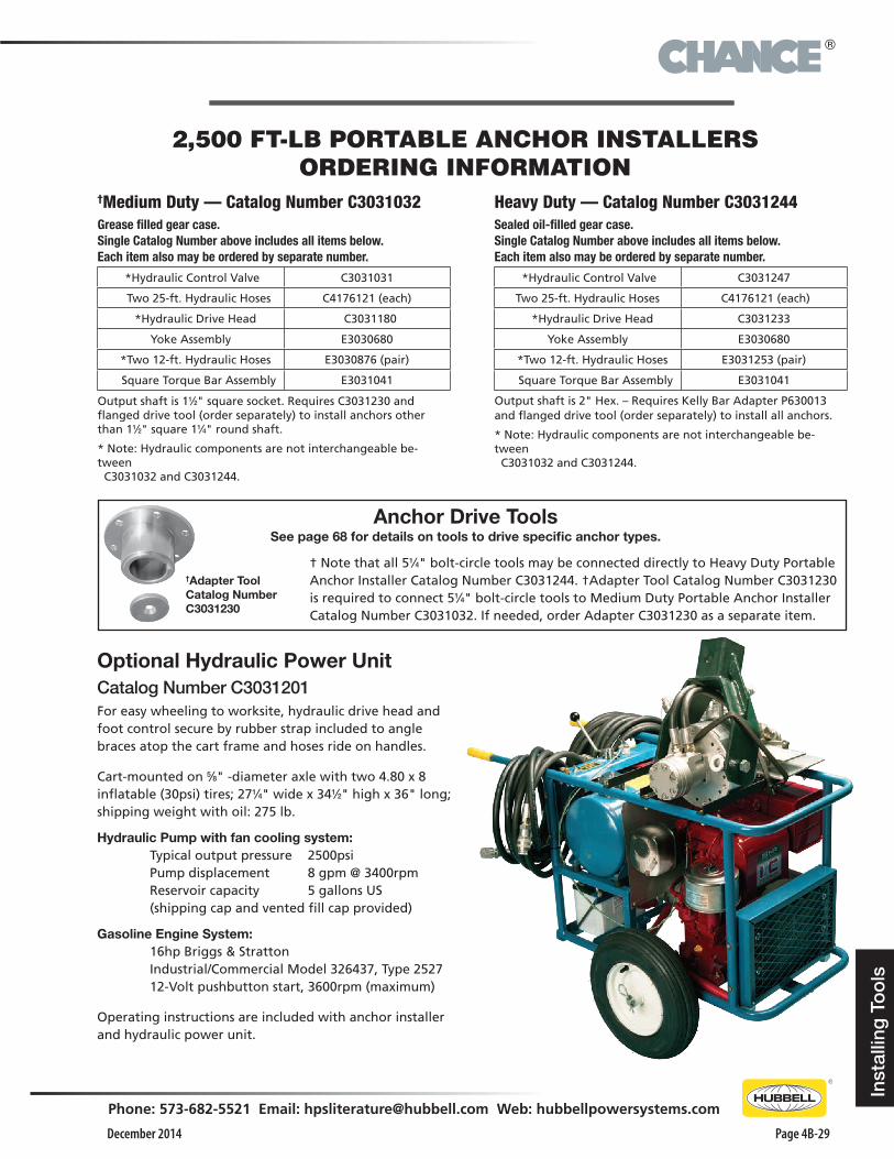
Optional Hydraulic Power Unit Catalog Number C3031201For easy wheeling to worksite, hydraulic drive head and foot control secure by rubber strap included to angle braces atop the cart frame and hoses ride on handles.
Cart-mounted on 5⁄8" -diameter axle with two 4.80 x 8 inflatable (30psi) tires; 271⁄4" wide x 341⁄2" high x 36" long; shipping weight with oil: 275 lb.
Hydraulic Pump with fan cooling system: Typical output pressure 2500psi Pump displacement 8 gpm @ 3400rpm Reservoir capacity 5 gallons US (shipping cap and vented fill cap provided)
Gasoline Engine System: 16hp Briggs & Stratton Industrial/Commercial Model 326437, Type 2527 12-Volt pushbutton start, 3600rpm (maximum)
Operating instructions are included with anchor installer and hydraulic power unit.
2,500 FT-LB PORTABLE ANCHOR INSTALLERSORDERING INFORMATION
†Medium Duty — Catalog Number C3031032Grease filled gear case. Single Catalog Number above includes all items below. Each item also may be ordered by separate number.
*Hydraulic Control Valve C3031031
Two 25-ft. Hydraulic Hoses C4176121 (each)
*Hydraulic Drive Head C3031180
Yoke Assembly E3030680
*Two 12-ft. Hydraulic Hoses E3030876 (pair)
Square Torque Bar Assembly E3031041
Output shaft is 11⁄2" square socket. Requires C3031230 and flanged drive tool (order separately) to install anchors other than 11⁄2" square 11⁄4" round shaft.
* Note: Hydraulic components are not interchangeable be-tween C3031032 and C3031244.
Heavy Duty — Catalog Number C3031244Sealed oil-filled gear case. Single Catalog Number above includes all items below. Each item also may be ordered by separate number.
*Hydraulic Control Valve C3031247
Two 25-ft. Hydraulic Hoses C4176121 (each)
*Hydraulic Drive Head C3031233
Yoke Assembly E3030680
*Two 12-ft. Hydraulic Hoses E3031253 (pair)
Square Torque Bar Assembly E3031041
Output shaft is 2" Hex. – Requires Kelly Bar Adapter P630013 and flanged drive tool (order separately) to install all anchors.
* Note: Hydraulic components are not interchangeable be-tween C3031032 and C3031244.
®
December 2014Page 4B-30
Phone: 573-682-5521 Email: [email protected] Web: hubbellpowersystems.com
Installing To
ols
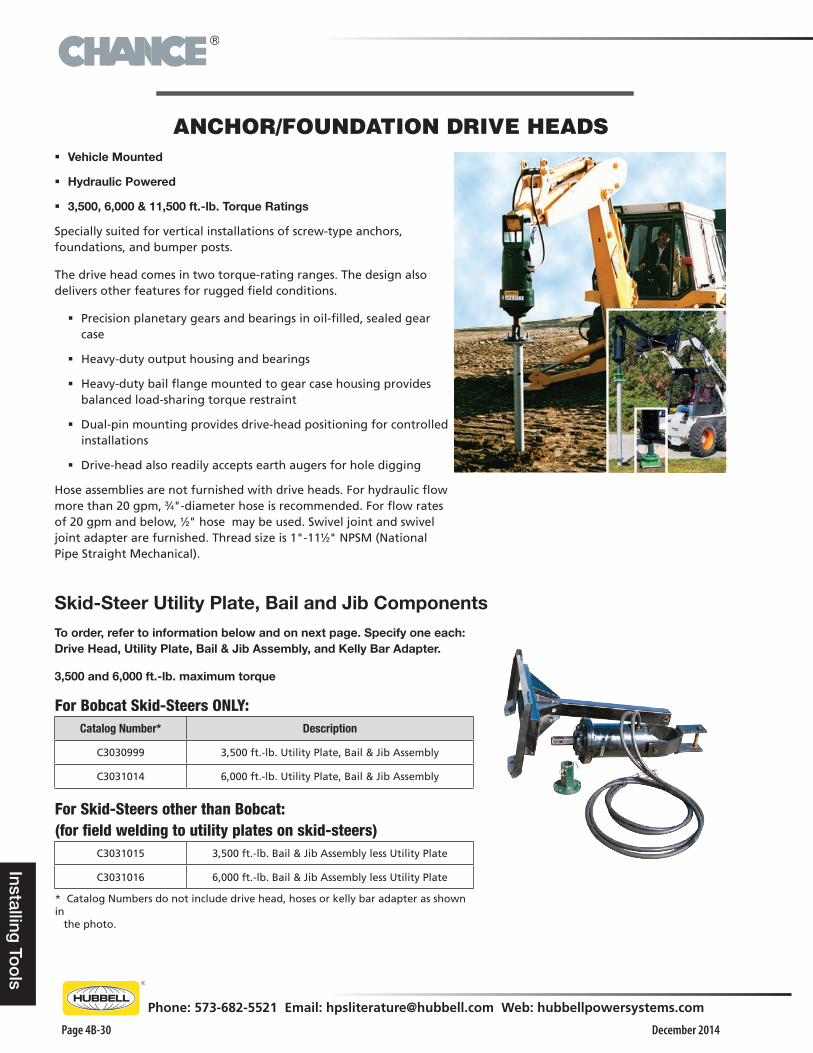
ANCHOR/FOUNDATION DRIVE HEADS � Vehicle Mounted
� Hydraulic Powered
� 3,500, 6,000 & 11,500 ft.-lb. Torque Ratings
Specially suited for vertical installations of screw-type anchors, foundations, and bumper posts.
The drive head comes in two torque-rating ranges. The design also delivers other features for rugged field conditions.
� Precision planetary gears and bearings in oil-filled, sealed gear case
� Heavy-duty output housing and bearings
� Heavy-duty bail flange mounted to gear case housing provides balanced load-sharing torque restraint
� Dual-pin mounting provides drive-head positioning for controlled installations
� Drive-head also readily accepts earth augers for hole digging
Hose assemblies are not furnished with drive heads. For hydraulic flow more than 20 gpm, 3⁄4"-diameter hose is recommended. For flow rates of 20 gpm and below, 1⁄2" hose may be used. Swivel joint and swivel joint adapter are furnished. Thread size is 1"-111⁄2" NPSM (National Pipe Straight Mechanical).
Skid-Steer Utility Plate, Bail and Jib ComponentsTo order, refer to information below and on next page. Specify one each: Drive Head, Utility Plate, Bail & Jib Assembly, and Kelly Bar Adapter.
3,500 and 6,000 ft.-lb. maximum torque
For Bobcat Skid-Steers ONLY:Catalog Number* Description
C3030999 3,500 ft.-lb. Utility Plate, Bail & Jib Assembly
C3031014 6,000 ft.-lb. Utility Plate, Bail & Jib Assembly
For Skid-Steers other than Bobcat: (for field welding to utility plates on skid-steers)
C3031015 3,500 ft.-lb. Bail & Jib Assembly less Utility Plate
C3031016 6,000 ft.-lb. Bail & Jib Assembly less Utility Plate
* Catalog Numbers do not include drive head, hoses or kelly bar adapter as shown in the photo.
®
December 2014
Phone: 573-682-5521 Email: [email protected] Web: hubbellpowersystems.com
Page 4B-31
Inst
allin
g T
oo
ls
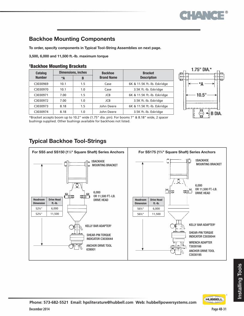
Typical Backhoe Tool-Strings
Backhoe Mounting ComponentsTo order, specify components in Typical Tool-String Assemblies on next page.
3,500, 6,000 and 11,500 ft.-lb. maximum torque
†Backhoe Mounting BracketsCatalogNumber
Dimensions, inches Backhoe Brand Name
BracketDescription*A B
C3030969 10.1 1.5 Case 6K & 11.5K ft.-lb. Eskridge
C3030970 10.1 1.0 Case 3.5K ft.-lb. Eskridge
C3030971 7.00 1.5 JCB 6K & 11.5K ft.-lb. Eskridge
C3030972 7.00 1.0 JCB 3.5K ft.-lb. Eskridge
C3030973 8.18 1.5 John Deere 6K & 11.5K ft.-lb. Eskridge
C3030974 8.18 1.0 John Deere 3.5K ft.-lb. Eskridge
*Bracket accepts boom up to 10.2" wide (1.75" dia. pin). For booms 7" & 8.18" wide, 2 spacer bushings supplied. Other bushings available for backhoes not listed.
For SS5 and SS150 (11⁄2" Square Shaft) Series Anchors For SS175 (13⁄4" Square Shaft) Series Anchors
†BACKHOE MOUNTING BRACKET
6,000OR 11,500 FT.-LB.DRIVE HEAD
KELLY BAR ADAPTER‡
ANCHOR DRIVE TOOL639001
SHEAR-PIN TORQUE INDICATOR C3030044
Headroom Dimension
Drive Head ft.-lb.
525⁄8" 6,000
525⁄8" 11,500
†BACKHOE MOUNTING BRACKET
6,000OR 11,500 FT.-LB.DRIVE HEAD
KELLY BAR ADAPTER‡
SHEAR-PIN TORQUE INDICATOR C3030044
WRENCH ADAPTERT3030166ANCHOR DRIVE TOOLC3030195
Headroom Dimension
Drive Head ft.-lb.
563⁄4” 6,000
563⁄4” 11,500
®
December 2014Page 4B-32
Phone: 573-682-5521 Email: [email protected] Web: hubbellpowersystems.com
Installing To
ols
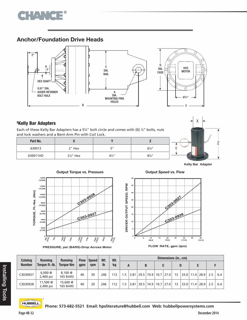
Output Torque vs. Pressure Output Speed vs. Flow
Anchor/Foundation Drive Heads
Catalog Number
Running Torque ft.-lb.
Running Torque Nm
Flowgpm
Speed rpm
Wt. lb
Wt. kg
Dimensions (in., cm)
A B C D E F
C30309276,000 @ 2,400 psi
8,100 @ 165 BARS
40 39 246 112 1.5 3.81 29.5 74.9 10.7 27.0 13 33.0 11.4 28.9 2.5 6.4
C303092811,500 @ 2,400 psi
15,600 @ 165 BARS
40 20 246 112 1.5 3.81 29.5 74.9 10.7 27.0 13 33.0 11.4 28.9 2.5 6.4
‡Kelly Bar AdaptersEach of these Kelly Bar Adapters has a 51⁄4" bolt circle and comes with (6) 1⁄2" bolts, nuts and lock washers and a Bent-Arm Pin with Coil Lock.
Part No. X Y Z
630013 2" Hex 5" 61⁄8"
630011HD 21⁄2" Hex 41⁄4" 81⁄8"
2"
0.81" DIA.AUGER RETAINERBOLT HOLE
HEX SHAFT
ADIA.
MOUNTING PINSHOLES
FC
DIA.BAIL
B E
6³/8"
DDIA.
CASEHYD
MOTOR
Kelly Bar Adapter
ZY
X
®
December 2014
Phone: 573-682-5521 Email: [email protected] Web: hubbellpowersystems.com
Page 4B-33
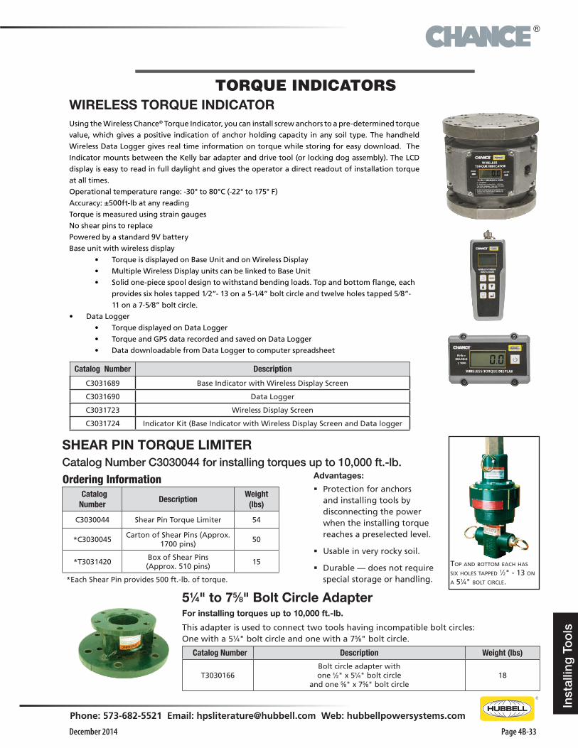
WIRELESS TORQUE INDICATORUsing the Wireless Chance® Torque Indicator, you can install screw anchors to a pre-determined torque
value, which gives a positive indication of anchor holding capacity in any soil type. The handheld
Wireless Data Logger gives real time information on torque while storing for easy download. The
Indicator mounts between the Kelly bar adapter and drive tool (or locking dog assembly). The LCD
display is easy to read in full daylight and gives the operator a direct readout of installation torque
at all times.
Operational temperature range: -30° to 80°C (-22° to 175° F)
Accuracy: ±500ft-lb at any reading
Torque is measured using strain gauges
No shear pins to replace
Powered by a standard 9V battery
Base unit with wireless display
• Torque is displayed on Base Unit and on Wireless Display
• Multiple Wireless Display units can be linked to Base Unit
• Solid one-piece spool design to withstand bending loads. Top and bottom flange, each
provides six holes tapped 1⁄2”- 13 on a 5-1⁄4” bolt circle and twelve holes tapped 5⁄8”-
11 on a 7-5⁄8” bolt circle.
• DataLogger
• Torque displayed on Data Logger
• Torque and GPS data recorded and saved on Data Logger
• Data downloadable from Data Logger to computer spreadsheet
Catalog Number Description
C3031689 Base Indicator with Wireless Display Screen
C3031690 Data Logger
C3031723 Wireless Display Screen
C3031724 Indicator Kit (Base Indicator with Wireless Display Screen and Data logger
Inst
allin
g T
oo
ls
TORQUE INDICATORS
51⁄4" to 75⁄8" Bolt Circle AdapterFor installing torques up to 10,000 ft.-lb.
This adapter is used to connect two tools having incompatible bolt circles: One with a 51⁄4" bolt circle and one with a 75⁄8" bolt circle.
Catalog Number Description Weight (lbs)
T3030166Bolt circle adapter withone 1⁄2" x 51⁄4" bolt circle
and one 5⁄8" x 75⁄8" bolt circle18
SHEAR PIN TORQUE LIMITER Catalog Number C3030044 for installing torques up to 10,000 ft.-lb.
Top and boTTom each has six holes Tapped 1⁄2" - 13 on a 51⁄4" bolT circle.
Ordering Information Catalog Number
DescriptionWeight
(lbs)
C3030044 Shear Pin Torque Limiter 54
*C3030045Carton of Shear Pins (Approx.
1700 pins)50
*T3031420Box of Shear Pins (Approx. 510 pins)
15
*Each Shear Pin provides 500 ft.-lb. of torque.
Advantages:
� Protection for anchors and installing tools by disconnecting the power when the installing torque reaches a preselected level.
� Usable in very rocky soil.
� Durable — does not require special storage or handling.
®
December 2014Page 4B-34
Phone: 573-682-5521 Email: [email protected] Web: hubbellpowersystems.com
Installing To
ols
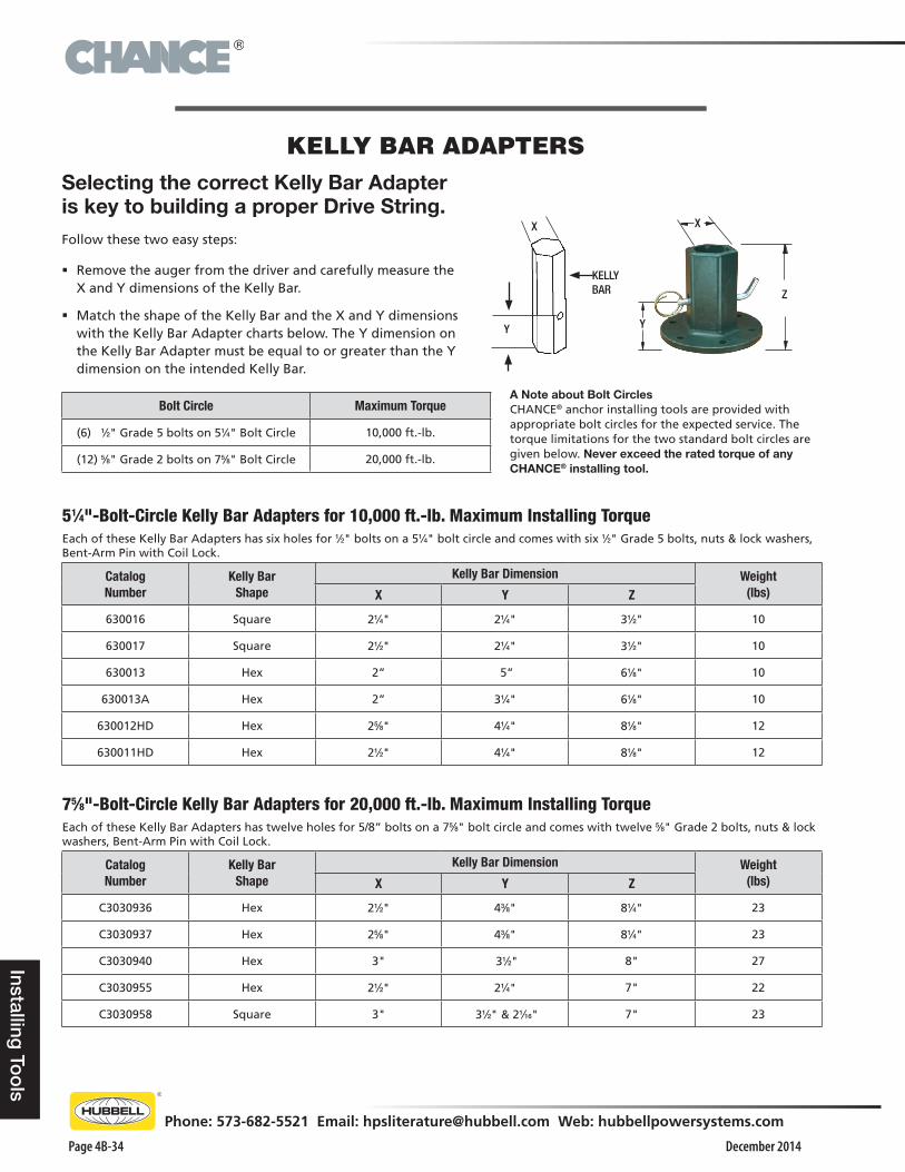
KELLY BAR ADAPTERS
X
Y
KELLY BAR
Selecting the correct Kelly Bar Adapter is key to building a proper Drive String.Follow these two easy steps:
� Remove the auger from the driver and carefully measure the X and Y dimensions of the Kelly Bar.
� Match the shape of the Kelly Bar and the X and Y dimensions with the Kelly Bar Adapter charts below. The Y dimension on the Kelly Bar Adapter must be equal to or greater than the Y dimension on the intended Kelly Bar.
51⁄4"-Bolt-Circle Kelly Bar Adapters for 10,000 ft.-lb. Maximum Installing TorqueEach of these Kelly Bar Adapters has six holes for 1⁄2" bolts on a 51⁄4" bolt circle and comes with six 1⁄2" Grade 5 bolts, nuts & lock washers, Bent-Arm Pin with Coil Lock.
CatalogNumber
Kelly BarShape
Kelly Bar Dimension Weight(lbs)X Y Z
630016 Square 21⁄4" 21⁄4" 31⁄2" 10
630017 Square 21⁄2" 21⁄4" 31⁄2" 10
630013 Hex 2” 5” 61⁄8" 10
630013A Hex 2” 31⁄4" 61⁄8" 10
630012HD Hex 25⁄8" 41⁄4" 81⁄8" 12
630011HD Hex 21⁄2" 41⁄4" 81⁄8" 12
75⁄8"-Bolt-Circle Kelly Bar Adapters for 20,000 ft.-lb. Maximum Installing TorqueEach of these Kelly Bar Adapters has twelve holes for 5/8” bolts on a 75⁄8" bolt circle and comes with twelve 5⁄8" Grade 2 bolts, nuts & lock washers, Bent-Arm Pin with Coil Lock.
CatalogNumber
Kelly BarShape
Kelly Bar Dimension Weight(lbs)X Y Z
C3030936 Hex 21⁄2" 43⁄8" 81⁄4" 23
C3030937 Hex 25⁄8" 43⁄8" 81⁄4" 23
C3030940 Hex 3" 31⁄2" 8" 27
C3030955 Hex 21⁄2" 21⁄4" 7" 22
C3030958 Square 3" 31⁄2" & 21⁄16" 7" 23
A Note about Bolt CirclesCHANCE® anchor installing tools are provided with appropriate bolt circles for the expected service. The torque limitations for the two standard bolt circles are given below. Never exceed the rated torque of any CHANCE® installing tool.
Bolt Circle Maximum Torque
(6) 1⁄2" Grade 5 bolts on 51⁄4" Bolt Circle 10,000 ft.-lb.
(12) 5⁄8" Grade 2 bolts on 75⁄8" Bolt Circle 20,000 ft.-lb.
Y
Z
X
®
December 2014
Phone: 573-682-5521 Email: [email protected] Web: hubbellpowersystems.com
Page 4B-35
Inst
allin
g T
oo
ls
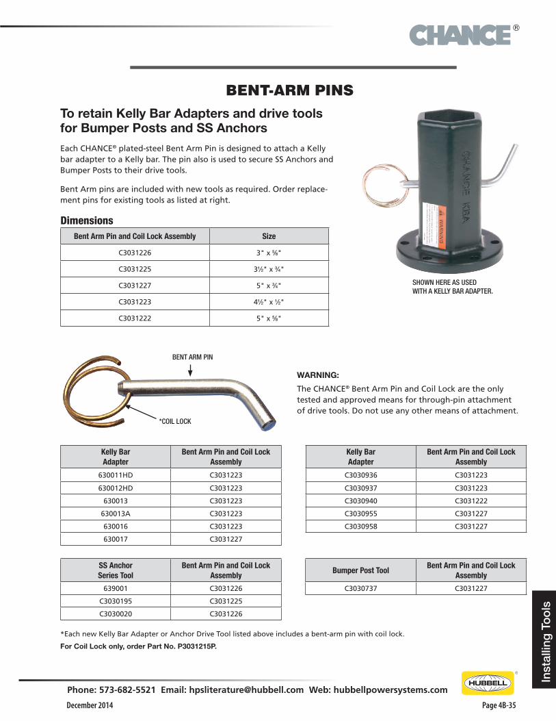
BENT-ARM PINSTo retain Kelly Bar Adapters and drive tools for Bumper Posts and SS AnchorsEach CHANCE® plated-steel Bent Arm Pin is designed to attach a Kelly bar adapter to a Kelly bar. The pin also is used to secure SS Anchors and Bumper Posts to their drive tools.
Bent Arm pins are included with new tools as required. Order replace-ment pins for existing tools as listed at right.
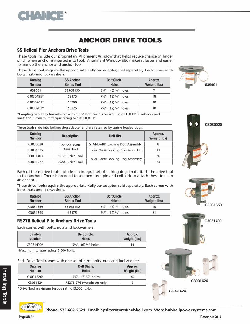
WARNING:
The CHANCE® Bent Arm Pin and Coil Lock are the only tested and approved means for through-pin attachment of drive tools. Do not use any other means of attachment.
SHOWN HERE AS USEDWITH A KELLY BAR ADAPTER.
*Each new Kelly Bar Adapter or Anchor Drive Tool listed above includes a bent-arm pin with coil lock.
For Coil Lock only, order Part No. P3031215P.
BENT ARM PIN
*COIL LOCK
DimensionsBent Arm Pin and Coil Lock Assembly Size
C3031226 3" x 5⁄8"
C3031225 31⁄2" x 3⁄4"
C3031227 5" x 3⁄4"
C3031223 41⁄2" x 1⁄2"
C3031222 5" x 5⁄8"
Kelly BarAdapter
Bent Arm Pin and Coil LockAssembly
Kelly BarAdapter
Bent Arm Pin and Coil LockAssembly
630011HD C3031223 C3030936 C3031223
630012HD C3031223 C3030937 C3031223
630013 C3031223 C3030940 C3031222
630013A C3031223 C3030955 C3031227
630016 C3031223 C3030958 C3031227
630017 C3031227
SS AnchorSeries Tool
Bent Arm Pin and Coil LockAssembly
639001 C3031226
C3030195 C3031225
C3030020 C3031226
Bumper Post ToolBent Arm Pin and Coil Lock
Assembly
C3030737 C3031227
®
December 2014Page 4B-36
Phone: 573-682-5521 Email: [email protected] Web: hubbellpowersystems.com
Installing To
ols
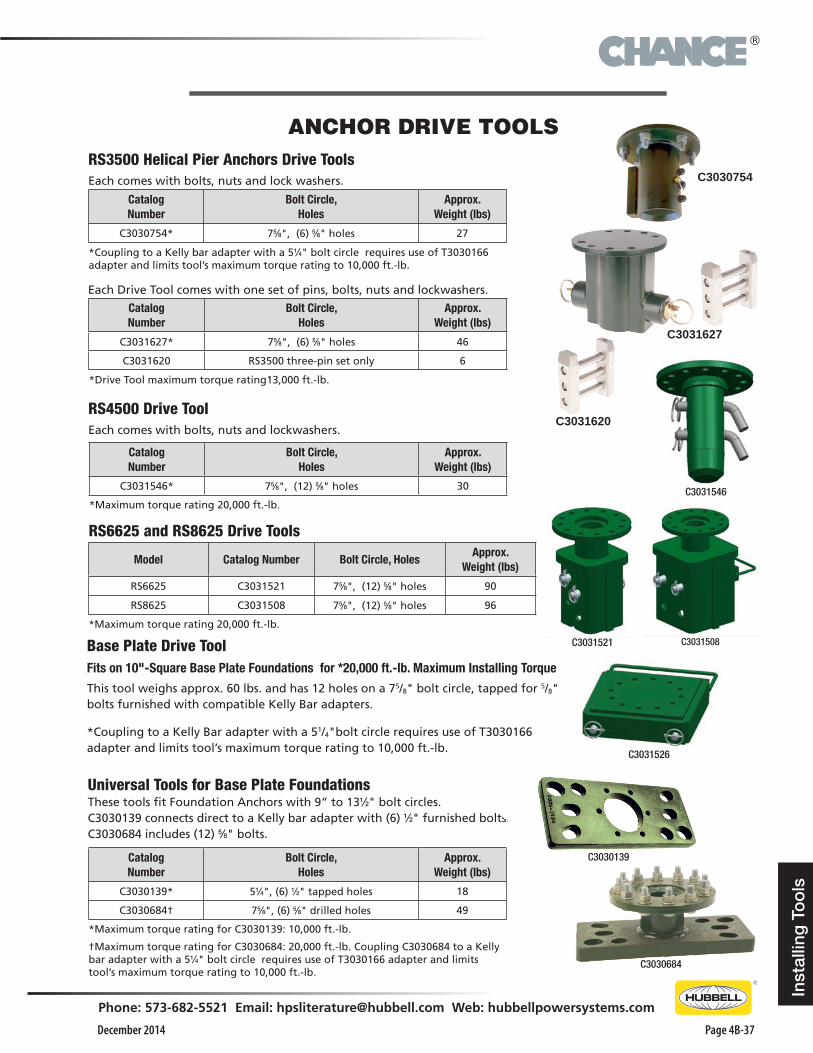
ANCHOR DRIVE TOOLSSS Helical Pier Anchors Drive ToolsThese tools include our proprietary Alignment Window that helps reduce chance of finger pinch when anchor is inserted into tool. Alignment Window also makes it faster and easier to line up the anchor and anchor tool.
These drive tools require the appropriate Kelly bar adapter, sold separately. Each comes with bolts, nuts and lockwashers.
CatalogNumber
SS Anchor Series Tool
Bolt Circle,Holes
Approx. Weight (lbs)
639001 SS5/SS150 51⁄4" , (6) 1⁄2" holes 7
C3030195* SS175 75⁄8", (12) 5⁄8" holes 18
C3030201* SS200 75⁄8", (12) 5⁄8" holes 30
C3030202* SS225 75⁄8", (12) 5⁄8" holes 30
*Coupling to a Kelly bar adapter with a 51⁄4" bolt circle requires use of T3030166 adapter and limits tool’s maximum torque rating to 10,000 ft.-lb.
RS278 Helical Pile Anchors Drive ToolsEach comes with bolts, nuts and lockwashers.
CatalogNumber
Bolt Circle,Holes
Approx. Weight (lbs)
C3031490* 51⁄4", (6) 1⁄2" holes 19
*Maximum torque rating10,000 ft.-lb.
C3030020
639001
Each of these drive tools includes an integral set of locking dogs that attach the drive tool to the anchor. There is no need to use bent arm pin and coil lock to attach these tools to an anchor.
These drive tools require the appropriate Kelly bar adapter, sold separately. Each comes with bolts, nuts and lockwashers.
C3031650
CatalogNumber
Description Unit fits:Approx.
Weight (lbs)
C3030020 SS5/SS150/RR Drive Tool
STANDARD Locking Dog Assembly 8
C3031035 Tough one® Locking Dog Assembly 11
T3031403 SS175 Drive ToolTough one® Locking Dog Assembly
26
C3031077 SS200 Drive Tool 23
These tools slide into locking dog adapter and are retained by spring loaded dogs.
CatalogNumber
SS Anchor Series Tool
Bolt Circle,Holes
Approx. Weight (lbs)
C3031650 SS5/SS150 51⁄4" , (6) 1⁄2" holes 10
C3031645 SS175 75⁄8", (12) 5⁄8" holes 21
Each Drive Tool comes with one set of pins, bolts, nuts and lockwashers.
CatalogNumber
Bolt Circle,Holes
Approx. Weight (lbs)
C3031626* 75⁄8", (6) 5⁄8" holes 44
C3031624 RS278.276 two-pin set only 5
*Drive Tool maximum torque rating13,000 ft.-lb.
C3031626
C3031490
C3031624
®
December 2014
Phone: 573-682-5521 Email: [email protected] Web: hubbellpowersystems.com
Page 4B-37
Inst
allin
g T
oo
ls
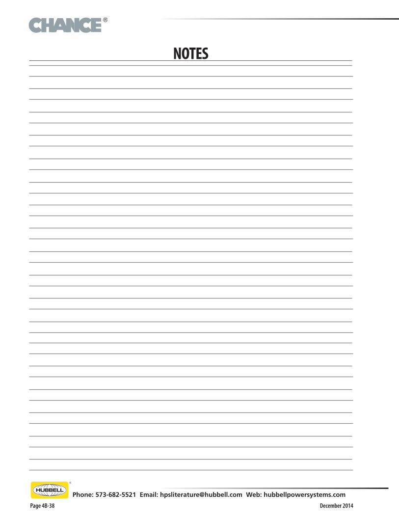
RS3500 Helical Pier Anchors Drive ToolsEach comes with bolts, nuts and lock washers.
CatalogNumber
Bolt Circle,Holes
Approx. Weight (lbs)
C3030754* 75⁄8", (6) 5⁄8" holes 27
*Coupling to a Kelly bar adapter with a 51⁄4" bolt circle requires use of T3030166 adapter and limits tool’s maximum torque rating to 10,000 ft.-lb.
Universal Tools for Base Plate FoundationsThese tools fit Foundation Anchors with 9” to 131⁄2" bolt circles.C3030139 connects direct to a Kelly bar adapter with (6) 1⁄2" furnished bolts. C3030684 includes (12) 5⁄8" bolts.
CatalogNumber
Bolt Circle,Holes
Approx. Weight (lbs)
C3030139* 51⁄4", (6) 1⁄2" tapped holes 18
C3030684† 75⁄8", (6) 5⁄8" drilled holes 49
*Maximum torque rating for C3030139: 10,000 ft.-lb.
†Maximum torque rating for C3030684: 20,000 ft.-lb. Coupling C3030684 to a Kelly bar adapter with a 51⁄4" bolt circle requires use of T3030166 adapter and limits tool’s maximum torque rating to 10,000 ft.-lb.
C3030139
C3030684
ANCHOR DRIVE TOOLS
Base Plate Drive Tool Fits on 10"-Square Base Plate Foundations for *20,000 ft.-lb. Maximum Installing Torque
This tool weighs approx. 60 lbs. and has 12 holes on a 75/8" bolt circle, tapped for 5/8" bolts furnished with compatible Kelly Bar adapters.
*Coupling to a Kelly Bar adapter with a 51/4"bolt circle requires use of T3030166 adapter and limits tool’s maximum torque rating to 10,000 ft.-lb.
RS4500 Drive ToolEach comes with bolts, nuts and lockwashers.
CatalogNumber
Bolt Circle,Holes
Approx. Weight (lbs)
C3031546* 75⁄8", (12) 5⁄8" holes 30
*Maximum torque rating 20,000 ft.-lb.
Model Catalog Number Bolt Circle, HolesApprox.
Weight (lbs)
RS6625 C3031521 75⁄8", (12) 5⁄8" holes 90
RS8625 C3031508 75⁄8", (12) 5⁄8" holes 96
*Maximum torque rating 20,000 ft.-lb.
RS6625 and RS8625 Drive Tools
C3031508C3031521
C3031546
C3031526
Each Drive Tool comes with one set of pins, bolts, nuts and lockwashers.
CatalogNumber
Bolt Circle,Holes
Approx. Weight (lbs)
C3031627* 75⁄8", (6) 5⁄8" holes 46
C3031620 RS3500 three-pin set only 6
*Drive Tool maximum torque rating13,000 ft.-lb.
C3031627
C3030754
C3031620
®
December 2014Page 4B-38
Phone: 573-682-5521 Email: [email protected] Web: hubbellpowersystems.com
NOTES
®
December 2014
Phone: 573-682-5521 Email: [email protected] Web: hubbellpowersystems.com
Page 4B-39
NOTES
®
December 2014Page 4B-40
Phone: 573-682-5521 Email: [email protected] Web: hubbellpowersystems.comDecember 2014
NEVER COMPROMISE™
www.hubbellpowersystems.com
• 210 N. Allen St. • Centralia, MO 65240 • (573) 682-5521
NOTE: Hubbell has a policy of continuous product improvement. We reserve the right to change design and specifications without notice. ©Copyright 2014 Hubbell Incorporated
Catalog 4B
NOTICE: For the latest revision of our Catalog and Literature, click here or visit our web site: www.hubbellpowersystems.com