emi design techniques for microcontrollers in automotive
TRANSCRIPT

APPLICATIONNOTE
AP-711
February 1996
EMI Design Techniques forMicrocontrollers inAutomotive Applications
CHRIS BANYAI
Technical Marketing EngineerIntel Automotive Operations
DARYL GERKE
EMC Consulting EngineerKimmel Gerke Associates, Ltd.
Order Number: 272673-001

Information in this document is provided in connection with Intel products. Intel assumes no liability whatsoev-er, including infringement of any patent or copyright, for sale and use of Intel products except as provided inIntel’s Terms and Conditions of Sale for such products.
Intel retains the right to make changes to these specifications at any time, without notice. MicrocomputerProducts may have minor variations to this specification known as errata.
*Other brands and names are the property of their respective owners.
²Since publication of documents referenced in this document, registration of the Pentium, OverDrive andiCOMP trademarks has been issued to Intel Corporation.
Contact your local Intel sales office or your distributor to obtain the latest specifications before placing yourproduct order.
Copies of documents which have an ordering number and are referenced in this document, or other Intelliterature, may be obtained from:
Intel CorporationP.O. Box 7641Mt. Prospect, IL 60056-7641
or call 1-800-879-4683
COPYRIGHT © INTEL CORPORATION, 1996

CONTENTS PAGE
AUTOMOTIVE EMI PROBLEMS ÀÀÀÀÀÀÀÀÀÀÀ 1
EMI DESIGN STRATEGIES ÀÀÀÀÀÀÀÀÀÀÀÀÀÀÀÀ 8
EMI CIRCUIT BOARD GUIDELINES ÀÀÀÀÀÀ 10
INTEL SPONSORED TEST PROJECT ÀÀÀÀ 18
CONTENTS PAGE
SUMMARY ÀÀÀÀÀÀÀÀÀÀÀÀÀÀÀÀÀÀÀÀÀÀÀÀÀÀÀÀÀÀÀ 21
REFERENCES ÀÀÀÀÀÀÀÀÀÀÀÀÀÀÀÀÀÀÀÀÀÀÀÀÀÀÀÀ 21
APPENDIX A ÀÀÀÀÀÀÀÀÀÀÀÀÀÀÀÀÀÀÀÀÀÀÀÀÀÀÀÀ A-1


AP-711
Electronics content of automobiles and other vehicleshas grown rapidly in recent years. Embedded micro-controllers are used in a wide range of vehicle applica-tions for control, convenience, and comfort. Examplesrange from sophisticated engine and braking controls toautomated radios and individual passenger temperaturecontrols.
As the electronics content of vehicles have increased, sohave the electromagnetic interference (EMI) problems.These range from annoyances (jamming an on-boardAM of FM radio) to upset or damage (blowing out anengine control module due to power transients.) Theproblems are expected to get worse as system clockspeeds and logic edge rates increase, due to increasedEMI emissions and decreased EMI immunity.
This application note describes the automotive EMI en-vironments, and then discusses how to identify and pre-vent many common EMI problems at the design stage.Although a range of solutions will be addressed, em-phasis is on printed circuit board design methods.
This application note also describes some recent Intelsponsored research efforts that investigate EMI to on-board FM radio receivers. Several different design ap-proaches were tested, using both two layer and multi-layer circuit boards. The test program was based on anABS (anti-lock braking system) control module thatuses the Intel 80C196KR microcontroller. The resultsand recommended ‘‘low noise’’ design concepts, howev-er, apply to any microcontroller design used in vehicu-lar applications.
AUTOMOTIVE EMI PROBLEMS
Vehicle electronics are affected by several factors, in-cluding harsh environments, high reliability, and ex-treme cost sensitivity. Fortunately, these problems canbe overcome through good EMI design techniques.
The automotive environment contains several threats,including power transients, radio frequency interfer-ence (both to and from nearby or onboard radio trans-mitters and receivers), electrostatic discharge, and pow-er line electric and magnetic fields. Since vehicles cango almost anywhere, the worst case situations must beassumed.
Vehicular electronics must be designed for extremelyhigh reliability. Even a single failure over millions ofvehicles may not be tolerated. Furthermore, any systemthat affects vehicle safety must be ‘‘fail-safe.’’ Systemsmust also be easy to install, test, and repair. And ofcourse, all of this must be done at the lowest possiblecost.
Here some comments on common EMI threats that arefaced by the designers of vehicle electronics. They aredivided into two broad classesÐsusceptibility (also re-ferred to as immunity) and emissions. In the first case,the automotive electronics are the victim of EMI, andin the second case, the automotive electronics are thesource of EMI.
Automotive EMI Susceptibility
Since the automotive environment is so severe, manyautomotive electronics designers are already well versedin dealing with the following EMI problems. Neverthe-less, we’ll review them here, since understanding theproblems is the first step toward solving them.
Power TransientsÐVehicle electrical systems are a richsource of power transients. Seven of the most severehave been characterized and have become a suite ofstandard EMI test pulses, as described in SAE J1113,‘‘Electromagnetic Susceptibility Procedures for VehicleComponents’’. These transients include pulses that sim-ulate both normal and abnormal conditions, includinginductive load switching, ignition interruption or turn-off, voltage sag during engine starting, and the alterna-tor ‘‘load dump’’ transient. The last is particularlyharsh, and can destroy unprotected electronic devices.For more information on these transients, see SAEJ1113.
All of these transients can damage or upset electronicsystems. Digital circuits are particularly susceptible totransients, which can result in false triggering or‘‘flipped bits’’ in memory. As electronic devices becomefaster and smaller, they become even more vulnerableto these transient spikes.
Radio Frequency ImmunityÐSince vehicles are often aplatform for land mobile radio transmitters, the on-board electronics systems may be exposed to very highradio frequency (RF) electromagnetic field levels. Thevehicles can also be exposed to high levels from exter-nal threats, like high powered radio stations or airportradar systems.
The ‘‘electric field’’ levels from these threats can easilyreach 50–100 volts/meter. In order to protect againstthese threats, test levels of up to 200 volts/meter arespecified for automotive applications. Since typical fail-ure levels for unprotected electronic systems are in the1–10 volt/meter range, substantial RF protection mustbe provided for electronic systems operating in the au-tomotive environment.
1

AP-711
Although both digital and analog circuits are vulnera-ble to the RF threat, low level analog circuits, such assensors, are the most vulnerable. A common failuremode is ‘‘RF rectification’’, which occurs when an ana-log circuit is driven non-linear by a large signal inducedby large RF fields. Voltage regulators can also be af-fected if the RF energy gets into the feedback loop ofthe regulator. Due to their higher operating margins,digital circuits are not as vulnerable to this threat, buteven they can be affected at high RF levels when usingtwo layer boards.
It’s easy to predict electric field levels if you know thetransmitter power and distance, using the following for-mula:
E e 5.50AP/d
where E is the electric field level in Volts/meterP is the transmitter output power in wattsA is the gain of the antenna (the product of AP iseffective radiated power)d is the distance from the antenna in meters
This formula assumes an isotropic or ‘‘uniform point’’source, and assumes no intervening shielding betweenthe transmitter and the vulnerable electronics. Never-theless, it’s quite accurate, particularly at the citizensband, land mobile, and television frequencies of25 MHz and higher. Most radio frequency interferencesusceptibility problems occur at these higher frequen-cies, where the cables and even circuit traces can act asefficient antennas.
Table 1. Electric Field Levels vs Distance and
Power (Free SpaceÐIsotropic Source)
1 10 100 100,000
Watt Watts Watts Watts
1 meter 5.5 V/m 17.3 V/m 55 V/m 1730 V/m
10 meters 0.55 V/m 1.73 V/m 5.5 V/m 173 V/m
100 meters 55 mV/m 0.17 V/m 0.55 V/m 17.3 V/m
1 kilometer 5.5 mV/m 17 mV/m 55 mV/m 1.73 V/m
Table 1 gives some examples. Note distance is critical,and even a low power hand held (walkie-talkie) radio iscapable of high field levels when it is close to the victimelectronics. A 1 watt hand held radio at 1 meter resultsin about 5 volts/meter, while a 100 watt transmitter(typical of many fixed mobile transmitters) at 1 meterresults in over 50 volts/meter. Both levels are muchhigher than from a 100,000 watt radio broadcast stationlocated 1000 meters away. In vehicles, the local on-
board transmitter is usually the biggest RF threat. Evenlow powered cellular phones can cause interferenceproblems, if their antenna is close to victim electronics.
Electrostatic Discharge (ESD)ÐSince almost every ve-hicle has humans on board, and since humans are aready source of ESD, this is another major EMI threatto vehicular electronics.
Most ESD requirements are based on the ‘‘human bodymodel’’, which characterizes typical voltages, currents,and risetimes associated with a human ESD event. Al-though ESD discharges are usually specified in ‘‘pre-discharge’’ voltage levels, it’s actually the current pulsethat causes most of the problems. Like water runningdown a river bed after the dam breaks, the ESD currentcan upset or destroy any vulnerable electronics in itspath. Furthermore, the electromagnetic field associatedwith the ESD event can also radiate into nearby elec-tronics systems, causing even more upsets. This isknown as the ‘‘indirect effect’’ of ESD.
Figure 1 shows the ESD current pulse resulting from ahuman ESD event. Note that this ESD current has avery rapid risetime in the 1–2 nanosecond range, withpeak currents of 10 amps or more. A 1 nanosecondedge rate has an equivalent ‘‘bandwidth’’ of over300 MHz, so ESD is very much a high frequency issueand requires high frequency design solutions.
Because of this high frequency content, a ‘‘direct hit’’ isnot necessary. The intense electromagnetic fields caneasily upset a nearby system from an ‘‘indirect hit’’ ofESD. This effect has been observed up to 20 feet (6meters) away, and is a reason that ‘‘indirect’’ testing isnow included in recent international ESD test specifica-tions.
As mentioned above, the test specifications are usuallygiven in the ‘‘pre-discharge’’ voltage levels. Most auto-motive electronics are designed to withstand at least15 KV, a severe level that actually exceeds most humanESD levels.
Power Line FieldsÐSince vehicles can go almost any-where, and since power lines (and transformers) can bealmost anywhere, this threat must also be addressed invehicular designs.
Normally, this is not a problem for microcontrollerbased systems, since at 50 or 60 Hz, electromagneticfield coupling is not very efficient. Nevertheless, verylow analog level circuits can be affected by ‘‘stray’’magnetic and electric fields. Thus, power line field re-quirements are usually imposed on vehicular systems tomake sure no upsets occur due to this threat.
2

AP-711
272673–1
Figure 1. Typical Waveshape of ESD from Human Body
Automotive EMI Emissions
Almost all automobiles today have sensitive AM/FMradio receivers (or perhaps even a land mobile VHFradio), so emissions from digital circuits are one of thebiggest EMI problems facing today’s designer of vehicu-lar electronics. Most of the time the problem is annoy-ing, but in the case of emergency vehicles (police, fire,ambulance), jamming a radio receiver could be lifethreatening. As a result, most vehicle manufacturersnow require suppressing the offending emissions to ex-tremely low levels.
Why Commercial EMI Limits Don’t WorkÐThis prob-lem is similar to the radiated emissions from personal
computers, which results in the well known FCC (Unit-ed States) or CISPR (European) EMI limits for com-puters. These commercial limits are aimed at protectingnearby television receivers (3–10 meters away) frominterference. The military has similar limits with lowerlevels, designed to protect their radio communicationsand navigation systems from EMI.
Radiated emissions in the vehicular environment ismuch more severe than in the commercial or militaryenvironments. First, automotive radio receivers aremuch more sensitive than television receivers, and sec-ond, the offending circuits are much closer to the radioreceivers (commercial or military), typically within1 meter of the antenna.
3

AP-711
272673–2
Comparison of Radiated Emission Specifications Commercial (FCC), Military and Automotive.
Figure 2
Several vehicle manufacturers have responded withtheir own radiated emission limits that are well belowthe commercial or military limits. Figure 2 comparesthe commercial FCC limits with both military (MIL-STD-461) with the General Motors vehicle ‘‘module’’limits (GM9100) for radiated emissions. (All three setsof limits have been normalized to a 1 meter measure-ment distance.) In the FM broadcast range(88–108 MHz), the vehicle limits are about 6 mV/m(15 dB mV/m), which is about 300 times (50 dB) morestringent than corresponding commercial emission lim-its, and about 6 to 20 times (15–25 dB) more stringentthan corresponding military limits.
Most vehicle problems occur in the FM broadcast band(88-108 MHz) rather than the AM broadcast band(550 kHz–1600 kHz). At FM frequencies, the cablesact as efficient antennas due to the shorter wavelengths(3 meters for 100 MHz vs 300 meters for 1 MHz), soradiated emissions are much more efficient at thesehigher frequencies. On board VHF land mobile receiv-ers operating in the 140–170 MHz (amateur, police,fire, ambulances) can also be similarly affected. Onboard UHF land mobile receivers in the 450 MHzrange are not usually affected by today’s microcontrol-lers, but they will be as the clock speeds and edge ratescontinue to increase.
Microcontrollers as Unintended TransmittersÐThe pri-mary sources of emissions from microcontroller basedsystems are the clocks and other highly repetitive sig-nals. The harmonics of these signals result in discretenarrowband signals that can often be received well intothe VHF and UHF radio ranges. Although digital sys-tems are often classified as ‘‘unintentional radiators’’,these harmonics are easily radiated by cables, wiring,and printed circuit board traces.
Fourier analysis is a useful tool to understand theseharmonic emissions. The Fourier series shows that anynon-sinusoidal periodic waveform is composed of a fun-damental frequency plus harmonic frequencies. Fortu-nately, as the frequency increases, the amplitudes of theharmonics decrease. Unfortunately, square waves usedin digital systems decrease at the slowest rate (20 dB/decade), and therefore are rich sources of high frequen-cy harmonics. In a sense, a digital system is like a seriesof small radio transmitters that broadcast simulta-neously on a wide range of frequencies.
4

AP-711
Fourier Predictions
272673–3
Digital circuits are rich in harmonics, and act like multiple transmitters.
Figure 3
Figure 3 shows the relationship between the time andfrequency domains for a repetitive digital signal such asa clock. Although in the time domain it is customary toexpress data in a linear fashion, in the frequency do-main it is customary to express data in a logarithmicfashion. This ‘‘Bode-plot’’ approach provides additionalinsights, as slopes and break points become readily ap-parent.
A widely used EMI frequency is the transition fromb20 dB/decade to b40 dB/decade, which occurs at1/(qtr). This is often referred to as the ‘‘logic band-width’’, because this is the bandwidth necessary to passthe signal without degrading the edge rate. For exam-ple, the ‘‘logic bandwidth’’ of a 10 nanosecond edgerate is 32 MHz, while the ‘‘logic bandwidth’’ of a 1 nsecedge rate is 320 MHz. Since many systems today haveedge rates in the 1–3 nsec range, these systems are‘‘hot’’ with VHF and UHF energy. Note that this‘‘bandwidth’’ is only effected by the ‘‘edge rate’’ andnot the clock rate. Decreasing the edge rates will de-crease this bandwidth, and thus decrease the high fre-quency content of the digital signal.
Figure 4 shows the effect of increasing a clock rate, butkeeping the edge rate constant. In this case, the specificamplitude at a given frequency increases with the clockrate. Note that BOTH edge rates and clock rates contrib-ute to the radiated emissions that interfere with radioreceivers. Furthermore, the harmonicsÐnot the funda-mental clock frequencyÐcause the problems.
Cables and PCB Traces as Unintended AntennasÐForemissions to be a problem, we need both a ‘‘transmit-ter’’ and an ‘‘antenna.’’ We’ve already seen that repeti-tive digital signals act like multiple hidden transmitters.Now we’ll look at how cables and board traces act asmultiple ‘‘hidden antennas.’’
Figure 5 shows the effect of coupling the harmonicsdescribed above to a hidden antenna such as a cable.Although the harmonic frequency content decreaseswith frequency, the antenna efficiency increases withfrequency. The net result is a pretty good system fortransmitting VHF and UHF energy, even if it is unin-tended.
5

AP-711
How Fast Risetimes Cause Radiated Interference
272673–4
High speed sources plus long cables equals emissions.
Figure 4
Clock Rate Affects Emissions, Too
272673–5
3x clock rate e 10 dB higher emissions.The faster the clock frequency . . . the higher the emissions.
Figure 5
Any conductor will act as an efficient antenna when it’sphysical dimensions exceed a fraction of a wavelength.Since cables, by their very nature, are among the long-est conductors in a system, they are usually the mostsignificant ‘‘antennas.’’ At higher frequencies, however,even the traces on the circuit boards become longenough to radiate. The secret to success for radiatedemissions is to prevent high frequency energy from everreaching the hidden antennas.
As a rule of thumb, any wire over 1/20 wavelength isconsidered an antenna for EMI purposes. Most com-munications antennas are 1/4 wavelength or longer,but even ‘‘short’’ antennas are significant radiators. Ta-ble 2 shows some typical frequencies and lengths,which are related by the formula l e 300/f, where l isthe wavelength in meters, and f is the frequency inMegahertz. Also shows are ‘‘equivalent risetimes’’based on the ‘‘logic bandwidth’’ frequencies of digitalsignals, using the formula tr e 1000*f/q, where tr isthe risetime in nanoseconds and f is the frequency inMHz.
6

AP-711
Table 2. Frequency, Wavelength, Rise Time
FrequencyApprox.
Wavelength1/20
tr Wavelength
300 kHz 1 msec 1000 meters 150 meters
1 MHz 300 nsec 300 meters 15 meters
3 MHz 100 nsec 100 meters 5 meters
10 MHz 30 nsec 30 meters 1.5 meters
30 MHz 10 nsec 10 meters 50 cm
100 MHz 3 nsec 3 meters 15 cm
300 MHz 1 nsec 1 meter 5 cm
Based on the 1/20 wavelength criteria, a cable that is1.5 meters long is a good antenna for any frequencyabove about 10 MHz. Even a 15 centimeter meter cableis an effective radiator at 100 MHz, which is right inthe middle of the FM broadcast band. At 300 MHz, thecritical length drops to about 5 centimeters, so thateven the board traces themselves become significant ra-diators at frequencies above 300 MHz.
Both the board traces and the cables connected to thecircuit board can radiate, as shown in Figure 6. Thecable contribution is normally much more severe, dueto the large physical size of the cable. One can use an-tenna theory to predict the electric field levels radiated
by these unintended antennas. For board radiation, as-sume a small loop antenna, and for cable radiation, as-sume a larger dipole antenna. The formulas are as fol-lows:
E e 265 x 10b16 IAf2/r (Differential mode currentson the board)
E e 4 x 10b7 IfL/r (Common mode currents on thecable)
Where E is the electric field intensity in Volts/meter, Iis the current is amps, A is the ‘‘loop area’’ on thecircuit board, L is the cable length, and r is the distancefrom the antenna.
For example, 1 milliamp of differential mode current at100 MHz in a 1 square centimeter loop on the circuitboard results in an electric field intensity of about26 mV/m at a distance of 1 meter. For the same electricfield intensity, only 200 picoamps of common modecurrent at 100 MHz would be needed on a 1 meter longcable for the same field intensity.
For this example, both of these levels are still wellabove typical automotive limits of 6 mV/m. First, it’sobvious that if even a fraction of a percent of the PCBcurrents end up on the cables as common mode cur-rents, we’ve got a serious emissions problem. Second,it’s obvious that all high frequency currents (commonmode and differential mode) must be controlled at thecircuit board. There should be no doubt that the ‘‘hid-den antennas’’ can cause serious EMI problems.
Physical Dimensions (Antenna Effects)
272673–6
Loop Radiation (Differential Mode)ÐOn the boardÐSignal LoopsÐPower LoopsCable Radiation (Common Mode)ÐOff the board
Figure 6
7

AP-711
EMI DESIGN STRATEGIES
With all these potential EMI problems, it’s apparentEMI protection must be designed in from the begin-ning. Unfortunately, there is no ‘‘magic solution’’ forEMI. Rather, it must be addressed throughout the de-sign.
Different Approaches for DifferentThreats
Each of the EMI threats discussed earlier have pre-ferred strategies. In many cases, one strategy may ad-dress several threats at the same time. In all cases, mul-tiple levels of protection are needed.
Power TransientsÐThe design strategies for this threatare to provide primary transient protection on all mod-ule input power lines, plus secondary protection such asfiltering at the circuit level. The ‘‘load dump’’ transientis usually the biggest concern. Designing ‘‘noise toler-ant’’ software is also very effective in controlling sus-ceptibility to power line transients.
Radio Frequency ImmunityÐThe design strategies forthis threat are to keep the unwanted energy from reach-ing vulnerable circuits. This requires high frequency fil-tering on cables (both power and I/O) which act asantennas, plus careful circuit layout and circuit decou-pling. Cable and module shielding are also effective, butare not popular in vehicular designs due to the costs.
Electrostatic DischargeÐThe design strategies for ESDare to limit damage by transient suppression or highfrequency filtering on I/O and power lines, and to limitupsets by local filtering and decoupling, careful circuitlayouts, and perhaps even shielding. Many of the designtechniques for RF emissions and immunity work equal-ly well for the ‘‘indirect’’ ESD effects due to the tran-sient electromagnetic fields.
Power Line FieldsÐThe design strategies are usuallyinstrumentation oriented, and include local shieldingand filtering of the most critical circuits. The designtechniques necessary for RF emissions and immunityalso minimize this threat. This is normally not a seriousthreat.
Radiated EmissionsÐThe design strategies for thisproblem are to suppress the emissions at the source bycareful circuit layout, filtering, and grounding, or tocontain the emissions by shielding. For automotive de-
signs, the emphasis is usually on suppression and care-ful circuit layout, since shielding is costly and difficultfor most high volume automotive products. Neverthe-less, shielding is seeing increasing use in vehicular ap-plications.
EMI at the IC Level
As an integrated circuits vendor, we are often asked tomake our circuits ‘‘more quiet’’ or ‘‘more rugged’’ inhopes of solving the EMI problems. After all, everyonealways says to ‘‘suppress it at the source’’ or ‘‘harden atthe victim.’’ So why not just incorporate all the EMIfixes at the IC level, and be done with it?
If only life were so simple. While many equipment de-signers would like to push all the EMI responsibilityback to the chip vendors, this approach is not verypractical, due to constraints of chip speed, cost, per-formance, and wide temperature range. Lower EMIusually means slower speeds, which in turn means low-er performance. Yet the trend in automotive ICs istoward higher performance devices with increasingclock speeds and edge rates.
Nevertheless, as chip manufacturers we are workinghard to help control EMI at the IC level. For example,at Intel we’ve designed in the capability to turn off cer-tain high speed control lines when not needed. We’veredesigned clock drivers, and we’ve incorporated highfrequency power and grounding schemes right on thesilicon. We are working with a Society of AutomotiveEngineers Task Force to develop methods to measureand control EMI at the chip level. Our research intothese areas continues. But while these efforts help, wecan’t do it all, and the real battle against EMI must stillbe waged at the circuit and module stage.
EMI at the PCB Level
This is where the most effective automotive EMI re-sults can be achieved today. It’s also where the designerhas the most control. Many solutions at this level areinexpensive or even free, particularly when dealing withboard layout and routing. Later in this applicationnote, we’ll provide some specific PCB design guides,but here is some general EMI advice.
First, plan for EMI, right from the start. Identify themost critical circuits, and decide what to do aboutthem. Consider multi-layer boards, and allow for plentyof filtering and decoupling in the initial designs. Youcan always remove components later if you don’t needthem.
8

AP-711
Second, stay involved with the design. Most good EMIdesigns are the result of the design engineer and thePCB layout specialist working closely as a team. Asclock speeds and edge rates increase, this becomes evenmore important.
Third, test early and often. Unfortunately, EMI is notan exact science. Better to identity potential problemsearly in the design, when the alternates are inexpensiveand plentiful. Late in the design cycle, EMI solutionsmay be expensive and painful.
EMI is a necessary part of any vehicular electronic de-sign, and building in EMI suppression and hardness atthe PCB level is very sensible engineering. Not only willyou end up with an ‘‘EMI-proof’’ design, but you’lllikely have a more reliable design as well.
EMI at the Cable and InterconnectLevel
It is not usually cost effective to attack automotive EMIat this level. Cost and weight constraints generally pre-clude using shielded cables or expensive filtered con-nectors. Even external clamp on ferrites commonlyused with personal computers are not practical. Youcan, however, provide cost effective filtering and tran-sient protection at the I/O interface on the circuitboard.
Fiber optics may change this in the future. Fiber opticscan reduce and even eliminate many cable related EMIproblems, but this approach is still too expensive formost automotive applications. Even when fiber be-comes practical, however, the power wiring will stillneed EMI protection.
EMI at the Module Level
Like cable shielding, module shielding is often consid-ered too expensive for automotive applications. Never-theless, this approach should not be overlooked. It maybe less expensive to shield and filter a module than toadd a lot of components on the circuit board. This isparticularly true if the module must be enclosed forenvironmental protection.
There are two simple secrets to success with EMI mod-ule shielding. First, seal all seams, and second, filter allpenetrations. For most EMI problems, the material isnot critical, and even thin conductive coatings providevery high levels of protection. For example, nickel painton plastic typically provides 60 dB (a factor of 1000 ) or
more of protection, and vacuum plating or electrolessdeposition on plastic typically provides 80 dB (factor of10,000) of protection. A steel or aluminum box canprovide well over 120 dB (factor of 1,000,0000) of highfrequency shielding. These levels are easily attainable ifthe leaks (seams and penetrations) are sealed.
Good shielding need not be expensive. Consider the tel-evision-tuner, with its interlocking metal box and fil-tered input and output lines. This approach has beensuccessfully used for almost fifty years, to provide costeffective EMI control in a highly cost sensitive indus-try. There is an increasing trend toward similar shield-ed modules in vehicles.
EMI at the Software Level
Although normally not effective against emissions (al-though there have been cases where it did make a dif-ference), software can be very effective for EMI suscep-tibility. Like fault tolerance, you should build ‘‘noisetolerance’’ into your software.
There are two simple objectivesÐcatch the errors be-fore they upset the system, and then gracefully recover.It doesn’t take much to provide this protection, andoften times, just a few lines of code can work wonders.
To detect memory errors, add ‘‘checksums’’ to blocksof data in memory to tell when a memory state haschanged. To detect program errors, add ‘‘tokens’’ tomodules of code. Save the token on entering a module,and then check it on leaving the module. If they are notthe same, an error has occurred, since the module wasentered illegally. To detect I/O errors, do type andrange checking on the data.
A ‘‘watchdog’’ can prevent becoming lost in an endlesssoftware loop. This is often a separate device, althoughmany microcontrollers incorporate an internal watch-dog. If the watchdog is not reinitiated in a predeter-mined time, it resets the entire system, bringing it backto a known state.
Many of these techniques are already used in vehicularapplications with very good results. Often times theyare incorporated for safety reasons, but they are alsoeffective tools in the battle against EMI. For more de-tails on software techniques, see the Bibliography.
9

AP-711
EMI CIRCUIT BOARD GUIDELINES
Having examined problems and strategies, let’s look atsome specific solutions. We’ll focus on circuit boardissues, as this is where equipment designers have themost control. We’ll share some details on how to attackpotential EMI problems right at the root of almost allEMI problemsÐat the circuits and their interconnect-ing traces.
Guideline Ý1ÐIdentify Critical Circuits
The first step is to identify the most critical circuits onthe circuit board. Experience shows that most EMIproblems can be traced to a few key circuits. The goodnews is by identifying these circuits early, many EMIproblems can be prevented with very little effort.
EmissionsÐThe most critical circuits for EMI emis-sions are the highly repetitive circuits, such as clocks,address enables, and high speed data busses. Even sig-nals with low repetition rates, such as address bit 0, cancause problems with sensitive automotive radio receiv-ers. Consider adding a ferrite bead or small resistor(10–33 ohms) in series with any clock or other highspeed output, right at the driving pin. This will helpdamp any ringing, and also helps provide an impedancematch.
Both the signal traces, and the power traces are poten-tial sources. In the latter case, remember a chip that isswitching is consuming current in pulses, which canradiate just as well as signal current pulses. This meansthat any switched device is a potential source of emis-sions - not just the microcontroller. Figure 7 shows typ-ical emission paths from critical circuits.
Since clock lines are critical, position the chips to mini-mize any clock runs. As previously mentioned, keep theclock traces and crystals away form any connectors.Route the high speed lines first, and keep those linesshort and direct. Consider hand routing the criticallines, but if you use an autorouter, be sure to check tosee where the lines have been routed.
SusceptibilityÐThe most critical circuits for EMI sus-ceptibility are the reset, interrupt, and control lines. Theentire system can be brought to a halt if one of theselines are corrupted by EMI. Even though these circuitsmay have slow (or even nonexistent) repetition rates,they are still vulnerable to transients and spikes whichcan result in false triggering. Use high frequency filter-ing, such as small capacitors (0.001 mf typical) and fer-rite beads (or 100 ohm resistors) to protect these lines.These components should be installed right at the inputpins to the microcontroller.
Radiation and Coupling from Critical Circuits
272673–7
Figure 7
10

AP-711
Be especially careful with the reset circuitry, particular-ly when using external devices for watchdogs or detect-ing power loss. Any false triggering of these externalcircuits can cause a false reset, so these external circuitsmust be protected against EMI as well. Once again,small capacitors and ferrite beads or resistors are veryeffective as filters against spikes and transients.
Guideline Ý2ÐPlan your board layout
After identifying the most critical circuits, the nextconcern is where to place the circuits on the board.Although this sounds trivial, EMI success hinges onhow well this stage is implemented. Different circuitsinteract in subtle and unexpected ways, so you mustplan your layout.
Group the circuits by speed of operation. While thisseems obvious, this simple principle is often overlookedwith devastating EMI results. Figure 8 shows an exam-ple of a well partitioned board. Note that in this exam-ple, the high speed digital circuits are separated fromthe lower speed digital and analog circuits. Further-more, the high speed circuits are physically separatedfrom the I/O connectors to minimize parasitic high fre-quency coupling.
Use special care with the input-output circuits, sincethey connect to the outside world. Even though mostautomotive I/O circuits operate at relatively low fre-quencies, the cables still act as antennas for high fre-quency energy. A key concern here is location. A com-mon problem is placing a clock or crystal next to anI/O port, which results in parasitic coupling to the I/Owiring. A similar problem is routing reset or interruptlines next to I/O lines, which allow them to pick uptransients from the outside world. Keep these compo-nents and traces at least 25 mm (1 inch) away from anyinput/output or power connectors and wiring.
CLOCK MEDIUM/LOW LOW
CLOCK BUFFERS SPEED LOGIC FREQUENCY
HI-SPEED LOGIC DIGITAL I/O
MEMORY AD & AD LOW
FREQUENCY
ANALOG I/O
RIBBON CABLE DC POWER
CONNECTORS INPUT
Figure 8. Board Partitioning
11
AP-711
Guideline Ý3ÐSelect an appropriateboard type
The type of board has major impact on EMI issue, bothemissions and susceptibility. For years, automotive de-signers have used two layer boards due to cost con-straints. That trend is changing, and many new higherspeed designs now use multi-layer boards. There is nodoubt that multi-layer boards minimize and often elimi-nate EMI problems. Yet many simpler designs can bestill implemented with two layer boards, if proper de-sign techniques are used.
Multi-Layer Boards PreferredÐMulti-layer boards of-fer several EMI benefits. First, the power and signal‘‘loop areas’’ are minimized, both reducing emissionsand increasing immunity at the board. Second, thepower and ground impedance levels are lowered (oftenby several orders of magnitude) which reduces powerand ground perturbations. Third, the presence of powerand ground planes greatly minimize crosstalk betweentraces. As a result, multi-layer boards typically offerten-fold to hundred-fold EMI improvements over twolayer boards.
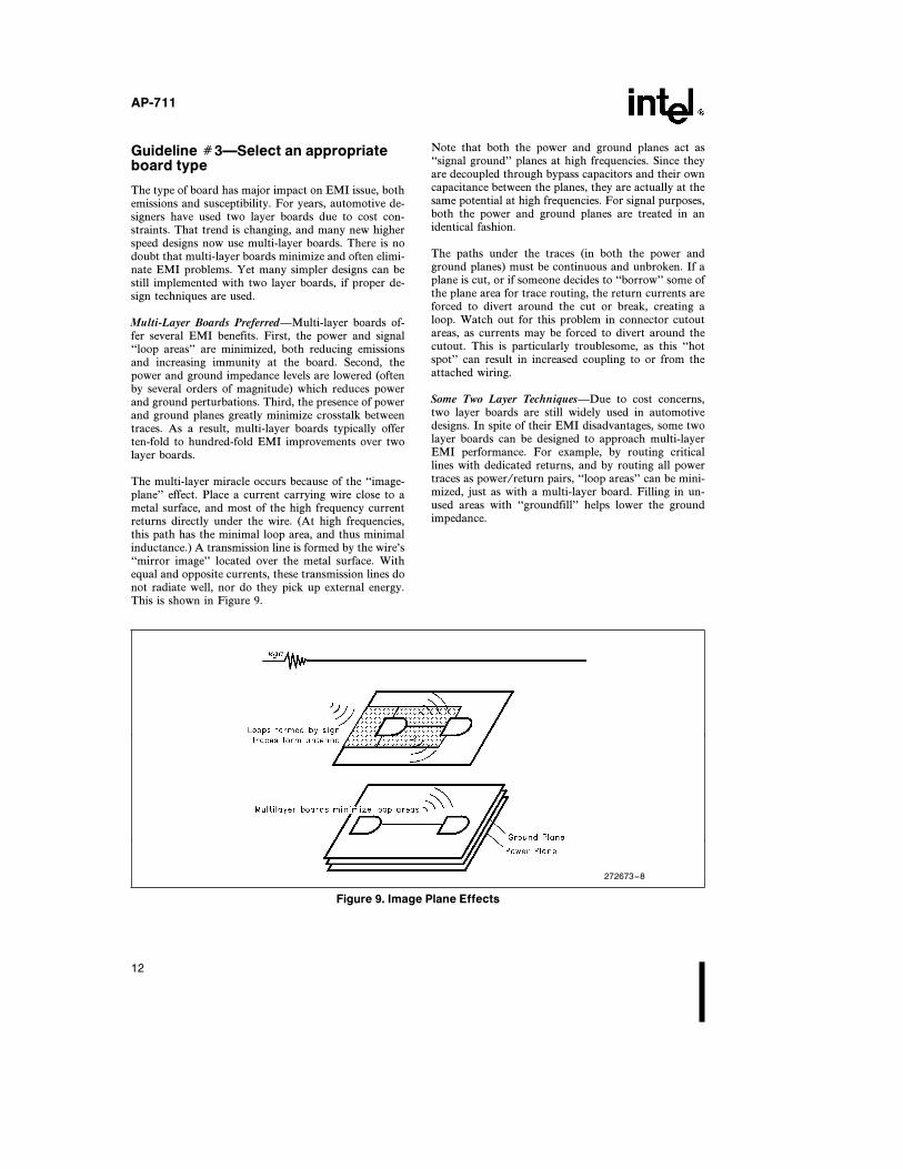
The multi-layer miracle occurs because of the ‘‘image-plane’’ effect. Place a current carrying wire close to ametal surface, and most of the high frequency currentreturns directly under the wire. (At high frequencies,this path has the minimal loop area, and thus minimalinductance.) A transmission line is formed by the wire’s‘‘mirror image’’ located over the metal surface. Withequal and opposite currents, these transmission lines donot radiate well, nor do they pick up external energy.This is shown in Figure 9.
Note that both the power and ground planes act as‘‘signal ground’’ planes at high frequencies. Since theyare decoupled through bypass capacitors and their owncapacitance between the planes, they are actually at thesame potential at high frequencies. For signal purposes,both the power and ground planes are treated in anidentical fashion.
The paths under the traces (in both the power andground planes) must be continuous and unbroken. If aplane is cut, or if someone decides to ‘‘borrow’’ some ofthe plane area for trace routing, the return currents areforced to divert around the cut or break, creating aloop. Watch out for this problem in connector cutoutareas, as currents may be forced to divert around thecutout. This is particularly troublesome, as this ‘‘hotspot’’ can result in increased coupling to or from theattached wiring.
Some Two Layer TechniquesÐDue to cost concerns,two layer boards are still widely used in automotivedesigns. In spite of their EMI disadvantages, some twolayer boards can be designed to approach multi-layerEMI performance. For example, by routing criticallines with dedicated returns, and by routing all powertraces as power/return pairs, ‘‘loop areas’’ can be mini-mized, just as with a multi-layer board. Filling in un-used areas with ‘‘groundfill’’ helps lower the groundimpedance.
272673–8
Figure 9. Image Plane Effects
12
AP-711
One technique is to use one layer as a dedicated groundplane. You don’t need multiple planes to benefit fromthe ‘‘image-plane’’ effect. In fact, on two layer boards,allocating one side as a dedicated ground plane produc-es benefits almost as good as a multi-layer board. Thisworks best on boards with low routing densities.
As an alternate to a dedicated plane, ground grids canbe used on two layer boards. One method accomplishesthis by running horizontal ground traces on one side ofthe board, and vertical ground traces on the other side.They are connected together at the crossover pointswith vias. In this way, both surfaces may be used forrouting, and yet a ground grid is provided for the highfrequencies. Although not as good as a plane, the gridapproach is still much more effective than randomtrace routing.
Even with care, however, it’s difficult to achieve EMIsuccess with two-layer technology on designs withclocks above about 15 MHz. As a result, we recom-mend multi-layer boards for new, high speed microcon-troller designs.
Design Guideline Ý4ÐIsolate WithCare
Isolated, or ‘‘split’’ planes have become very popular asa method of maintaining high frequency isolation on a
circuit board. This technique has been used for years onboards with mixed analog and digital circuits, and westrongly recommend it for those applications. In otherapplications, Intel recommends using extreme care withthis method. It is a useful technique, but if you do apoor job of isolating or segmenting the planes, you mayend with more problems that if you stayed with solidplanes.
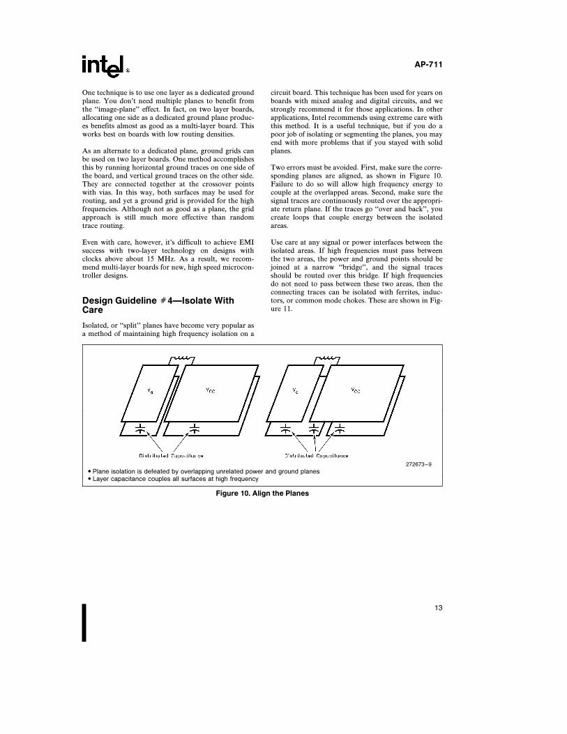
Two errors must be avoided. First, make sure the corre-sponding planes are aligned, as shown in Figure 10.Failure to do so will allow high frequency energy tocouple at the overlapped areas. Second, make sure thesignal traces are continuously routed over the appropri-ate return plane. If the traces go ‘‘over and back’’, youcreate loops that couple energy between the isolatedareas.
Use care at any signal or power interfaces between theisolated areas. If high frequencies must pass betweenthe two areas, the power and ground points should bejoined at a narrow ‘‘bridge’’, and the signal tracesshould be routed over this bridge. If high frequenciesdo not need to pass between these two areas, then theconnecting traces can be isolated with ferrites, induc-tors, or common mode chokes. These are shown in Fig-ure 11.
272673–9
# Plane isolation is defeated by overlapping unrelated power and ground planes# Layer capacitance couples all surfaces at high frequency
Figure 10. Align the Planes
13

AP-711
Micro-IslandÐThis term was coined by the EMI con-sulting firm of Kimmel Gerke Associates to describe anisolation design technique that has proven effective incontrolling EMI in embedded control systems. Proper-ly implemented, it provides many of the benefits of amulti-layer board even when using two layer boards.The technique typically yields ten fold reductions inradiated emissions over standard two layer boards. Thetechnique also works with multi-layer designs, but theyare generally more quiet in the first place.
For many automotive electronic systems, the embeddedmicrocontroller is the only high speed source of EMIon the board. If one can confine that high frequencyenergy to a small area (Micro-Island) on the board,EMI emissions can be minimized. This is accomplishedby providing a local ground plane under the high speedcircuitry (typically the microcontroller and perhapsRAM or ROM memory devices), and then filtering ev-ery trace (signal, power, and ground) entering or leav-ing the isolated island. A small shield could be added tocompletely encapsulate the island for even higher levelsof suppression, although this is rarely needed.
Here’s how to create your own Micro-Island. See Fig-ure 12 for details.
Ð First, define the boundaries of the island to encom-pass all high speed circuitry (microcontroller, crys-tal, RAM, ROM, etc.) Fill this area with a groundplane.
Ð Second, isolate every signal entering or leaving theisland with a T-filter (ferrite-capacitor or resistor-capacitor). The capacitors are connected to theground plane through a short lead.
Ð Third, isolate every power and ground trace with aseries ferrite bead. Decouple the power and groundwith a 0.01 mF capacitor at the capacitor energypoint.
Ð Fourth, any signal not starting or ending on Micro-Island must be routed around the island. Later inthis application note, we’ll share some test results ofthis technique.
Note that this example actually shows two islandsÐone for analog and one for digital. If you are not usinglow level analog signals, one island is sufficient.
272673–10
Figure 11. Routing Between Islands
14

AP-711
272673–11
1. Dedicated Digital Power/Ground Planes2. Dedicated Analog Power/Ground Planes3. Digital and Analog Power Decoupling4. I/O Decoupled with Ferrite/Resistor and Cap5. Grounded Crystal or Resonator
1. Ground Plane Under Micro-Controller2. Separate Analog Ground Plane3. Power Decoupled with Ferrite and Cap4. I/O Decoupled with Ferrite/Resistor and Cap5. Crystal or Resonator over Digital Ground Plane
Figure 12. Micro-Island
Guideline Ý5ÐDecouple the power
Many high frequency radiated emissions are caused bypoor power decoupling. While everyone intuitively un-derstands that high speed signals cause EMI, some for-get about the power perturbations. Whenever a digitalcircuit switches, it also consumes current at the switch-ing rate. These pulses of power current will radiate justas effectively as pulses of signal current. In fact, theyoften cause more radiation, since the power current lev-els are usually much higher than those on an individualsignal line.
High speed CMOS devices are particularly vexing,since they exhibit high peak currents due to the mo-mentary ‘‘short’’ across the power rails when theCMOS devices switch. In fact, CMOS peak currents areoften higher than other technologies, so emissions mayactually go up when a CMOS device (such as an80C31) is used to replace an HMOS (8031) device, eventhough the average power is much lower with CMOS.It’s the peak current, not average power, causing EMIemissions. The solution is to improve the power decou-pling.
Circuit decouplingÐWe recommend local power de-coupling of every integrated circuit on the board. Fordevices with multiple power and ground pins, each pairof pins should be decoupled. High frequency capacitorsin the 0.01–0.1 mf range should be installed as close aspossible to the device. For multi-layer boards, run ashort trace from the power pin to the capacitor, andthen drop the other lead into the ground plane. For twolayer boards, ‘‘fat’’ traces (with a length to width ratioof 5:1 or less) should be used on both the power andground sides of the capacitor to minimize inductance.In both cases, keep the leads as short as possible.
Additional protection can be provided by inserting aferrite in series with the VCC line to the microcontrol-ler. This must be installed on the VCC side of the capac-itor, not on the IC side. This small LC filter furtherisolates the VCC traces from current demands of theswitched device. We strongly recommend this tech-nique for two layer and Micro-Island designs; it’s op-tional for multi-layer designs.
15

AP-711
Power entry decouplingÐWe recommend high frequen-cy decoupling at the power entry points. In addition tothe standard 1–10 mf ‘‘bulk’’ capacitors, add a0.01–0.1 mf high frequency capacitor in parallel at thepower entry point. Due to internal resonances, the bulkcapacitors are useless at frequencies above about 1MHz. The high frequency capacitors are there to inter-cept any high frequency energy that tries to sneak outthe power interface. For more protection, series ferritescan also be added.
Be sure to keep the leads short on the decoupling ca-pacitors. The self-inductance of wires and traces isabout 8 nh/cm (20 nh/inch), so even a few millimetersof wire length can defeat the decoupling at high fre-quencies due to the inductance. Figure 13 gives severalexamples of how lead inductance defeats the decouplingcapacitor. Note that once you are above the resonantfrequency, using a larger capacitor provides no addi-tional benefits, as the inductive reactance prevails.
One more power decoupling hint. Add high frequencycapacitors (0.001 mf typical) to the input and outputs ofall on-board voltage regulators. This will protect thesedevices against high levels of RF energy (which canupset the feedback) and will also help suppress VHFparasitic oscillations from these devices. Keep the ca-pacitors close to the devices, with very short leads.
Guideline Ý6ÐBulletproof theinterfaces
We’ve already seen that cables and wiring can act asunintended antennas, and that even low levels on rela-tively short lengths can still cause EMI problems. Thus,we strongly recommend that you plan for filtering atyour power and signal connections to the module. Youmay find that you don’t need all of the filtering, but youcan always remove components depending on EMI testresults.
Power InterfacesÐWe already discussed high frequen-cy protection at the power inputs. A few high frequencycapacitors here is very cheap insurance, and they areoften needed for automotive designs to meet the ex-tremely low emission requirements. For immunity, ad-ditional low frequency filtering may also be needed,plus transient protection or energy storage for the auto-motive power transient requirements. Typically, meet-ing the ‘‘load dump’’ transient satisfies the other tran-sient requirements as well.
Signal InterfacesÐThese need some protection, too.Don’t assume that just because an interface is ‘‘slow’’that high frequency energy won’t try to enter or leavethe system at that point.
272673–12
Combination capacitance plus internal and external lead length:Larger capacitor moves resonant frequency down without providing any high frequency improvement
Figure 13. Capacitor Resonance
16

AP-711
As a minimum, provide the space and pads for highfrequency shunt capacitors and/or transient protectionon every line. Better yet, provide for a series resistor aswell. These can be ‘‘zero-ohm’’ resistors connected astraces between two pads. Cut and replace with actualresistors if necessary.
Don’t overlook the ground leads in the signal interface,as these can provide sneak paths for common modecurrents into and out of the system. We recommendadding a small ferrite bead in the ground lead, to com-plete the filtering of the interface.
Here are some additional recommendations on how toground shunt capacitors if filters. To contain emissions,connect the capacitor to the signal ground. The objec-tive is to keep these currents on the board. To enhanceimmunity, connect the capacitor to a chassis ground (if
available), not signal ground. The objective here is tokeep the offending currents off the circuit board.
If there is no chassis ground, then a compromise isnecessary for immunity. Connect the capacitor to thesignal ground, PLUS add a series element (ferrite orresistor) to limit the EMI current shunted into the sig-nal ground. This is mandatory for ESDÐif not used,the ESD current will likely ‘‘bounce’’ the ground withupset or damage as the result.
Guidelines Summary
Figure 14 summarizes some EMI-quiet circuit boardsolutions. By using these simple techniques, many EMIproblems can be minimized or eliminated.
Some EMI-Quiet PCB Solutions
272673–13
GOOD# 1. Parallel Power/Ground Traces# 2. Parallel Signal/Return Traces# 3. Power Decoupling at Chip# 4. Separation from I/O# 5. Separate I/O Power# 6. High Frequency Filter on I/O# 7. High Frequency Capacitor on Power
BETTER1. Multi-Layer Board2. Power Decoupling at Chip3. Separation from I/O4. Isolated I/O Power/Ground Plane5. High Frequency Filter on I/O6. High Frequency Capacitor on Power
Figure 14. Summary
17
AP-711
INTEL SPONSORED TEST PROJECT
In 1994, the Intel Automotive Operations in Chandler,Arizona, commissioned a research project to investigatethe effects of different printed circuit board techniqueson radiated electromagnetic interference emissions. Theproject involved laboratory testing of several designvariations of a ‘‘typical’’ automotive electronics moduleusing the Intel 80C196KR microcontroller. The em-phasis was on practical, low cost solutions that could beused by Intel automotive customers.
Test Methods and Procedures
The primary objective was to test several different cir-cuit board configurations for RF emissions in the 30–1000 MHz range. The test procedures were based onthe ‘‘module level’’ radiated emissions tests of GM9100.These procedures are used by General Motors to quali-fy electronic modules supplied by GM vendors, and areaimed at minimizing interference to vehicular radio re-ceivers when the modules are installed in the vehicle.The test levels are very stringent, with levels of 15 dBmV/m (6 mV/m) at 1 meter over most of the frequencyrange of interest. These levels are 50 to 100 timestougher to meet than those for personal computers.
Six board configurations were tested. All were based onan actual ABS module design. The representativeboards were populated with an 8XC196JT microcon-troller, regulator, load dump diode, and hex buffers.The fail-safe ASIC and other circuitry was simulatedby placing appropriate capacitor and resistor loads onthe test board. The component placement on the testboards was approximately the same as a fully populatedABS module. This was done since it imposed realisticPCB routing constraints on the test boards, and provid-ed realistic coupling paths on the test boards. Actualproduction connectors and cables were also installedduring the tests.
The six test configurations were as follows:
1. Standard Two Layer Layout
2. Two Layers with Micro-Island IsolationБ‘PoorImplementation’’
3. Two Layers with Micro-Island IsolationБ‘BetterImplementation’’
4. Standard Four Layer Layout
5. Standard Four Layer Layout with Micro-Island Iso-lation
6. Customer Supplied ABS ModuleÐPartially Popu-lated
Note that a key layout technique studies was the ‘‘Mi-cro-Island’’ technique discussed earlier. While this isnot a new concept, this method is a practical techniqueto isolate high frequency sources to one portion of thecircuit board. The intended effect is to eliminate highfrequency escape paths to the rest of the board and theinterconnecting cables. This high frequency isolationwas achieved by placing the control (80C196JT) andfail-safe microcontrollers on an island, and then filter-ing all traces bridging the island with ferrites and ca-pacitors.
Micro Island AnomaliesÐNote also that two versionsof the ‘‘Two-Layer Micro-Island’’ configuration weretested. Due to layout routing difficulties, the PCB de-signer compromised the micro-island technique by‘‘cutting up’’ the ground plane to route needed traces.The PCB designer believed, erroneously, that taking afew traces from the ground plane area would have min-imal impact. As is often the case in real designs, therewas no easy way to route all the traces without ‘‘bor-rowing’’ from the ground plane.
Rather than give up on the Two Layer Micro Islandapproach, the cuts were bridged with high frequencycapacitors. The objective was to create a high frequency‘‘grid’’ to minimize the effects of the cuts for the traces.While simple wire jumpers could have been used, ca-pacitors were chosen since this technique is often usedto ‘‘stitch’’ planes of different voltages together at highfrequencies. As it turns out, these two configurationsyielded some very significant test results.
Test Results & Conclusions
Figures 15–19 show the emissions from the various testmodule configurations. The tests showed primarysources of emissions were clock harmonics, as expected.At frequencies below 150 MHz, the interconnecting ca-ble was the primary antenna. At frequencies above150 MHz, both the cable and the board contributed tothe radiation. This is also consistent with expectations,given the wavelength and dimensions of the cables andboard traces.
Here are some conclusions based on the test resultsfrom the different board configurations:
Ð The standard two layer board had the poorest per-formance, and would likely fail GM9100.
Ð The four layer micro-island board was the best, andwould likely pass GM9100.
Ð The four layer standard board would also likelypass GM9100. However, it had higher emissionsabove 150 MHz than the four layer micro islandboard.
18

AP-711
Ð The two layer micro island board without the ca-pacitors would likely fail GM9100, but would likelypass with the addition of the auxiliary capacitorsand jumpers.
The experiments showed some other significant results,as follows:
Ð The four layer standard board was 10-25 dB morequiet than the two layer standard board.
Ð The properly executed two layer micro island boardapproached the results of the four layer micro-is-land board.
Ð The poorly executed two layer micro island boardwas almost no better than the standard two layerboard. Cutting the plane essentially destroyed themicro-island protection.
Ð A local shield positioned over the microcontrolleryielded 6 dB reductions. This was believed to be dueto reduced capacitive pickup of energy by the exter-nal cable
Additional near field tests were done on these testboards using strip lines, loop probes, and theEMSCANÉ board measurement system. While morefrequency components were noted in the near fieldtests, it was difficult to correlate these results with thefar field data.
In conclusion, the multi-layer board performed muchbetter than the same layout on a two layer board. Themicro-island approach is a viable solution, but it mustbe properly implemented. Finally, achieving the lowemission levels necessary for automotive applications ispossible, but difficult, with little room for design errors.
272673–14
Figure 15. Two Layer Standard
272673–15
Figure 16. Four Layer Standard
19

AP-711
272673–16
Figure 17. Two Layer Micro-Island
(Cuts in Ground Plane)
272673–17
Figure 18. Two Layer Micro-Island
(Capacitors to Repair Cuts)
272673–18
Figure 19. Four Layer Micro-Island
20

AP-711
SUMMARY
Automotive EMI problems are harsh. The susceptibili-ty levels are often high, and the radiated emission levelsare extremely low. The emission levels are particularlygrueling, as they require suppression to levels up to1000 times below commercial designs, and up to 100times below those for personal computers. Unfortunate-ly, there are no simple solutions to these problems.
We at Intel are committed to helping you solve theseproblems. We’ll continue our research and develop-ment at the chip level, doing what we can to control theEMI problems at that level. It should be apparent,however, we can’t do it all. EMI control must also beaddressed at the circuit board and module levels. We’llcontinue our efforts at these levels, too.
For additional help with these problems, we invite youto contact your Intel or Distributor Applications Engi-neers. Many have received introductory EMI training,and may be able to help you with basic questions. Formore involved problems, they can refer you to EMIdesign experts.
AcknowledgmentsÐThe main sources of the informa-tion for this application note are listed in the Referencesection. Daryl Gerke, PE., of Kimmel Gerke Associ-ates Ltd., was responsible for supplying much of thisinformation, and conducting the Intel sponsored testprogram. His firm specializes in EMI design, trouble-shooting, and training courses. Figures 1–14 are fromthe firm’s EMI training courses, and are used herecourtesy of Kimmel Gerke Associates Ltd. Mr. Gerkecan be reached in St. Paul, Minnesota, at612-330-3728.
REFERENCES:1. Gerke, D.D. and Kimmel, W.D., EDN’s Designer’s
Guide to Electromagnetic Compatibility, CahnersPublishing, Newton, MA, 1994
2. Williamson, T.W., Designing Microcontroller Sys-tems For Electrically Noisy Environments, Intel Ap-plication Note AP-125, 1982
3. Gerke, D.D. and Kimmel, W.D., ‘‘Focus on Auto-motive EMI’’, Kimmel Gerke Bullets, (EMI News-letter) Vol. 2, No. 4, Kimmel Gerke AssociatesLtd., 1991
4. Kimmel, W.D. and Gerke, D.D., ‘‘Microproces-sors and VHF RadiosÐMutual Antagonists, EMIEXPO 1989 Symposium Record, pp. C6.9-C6.22,August 1989
5. Gerke, D.D., ‘‘Designing Microcomputer Systemsto Tolerate Noise’’, Society of Automotive EngineersTransactions 870787, April 1987
6. Yarkoni, B. and Wharton, J. ‘‘Designing ReliableSoftware for Automotive Applications,’’ Society ofAutomotive Engineers Transactions 790237, Febru-ary 1979
7. SAE J1113, Electromagnetic Susceptibility Mea-surement Procedures for Vehicle Components, Soci-ety of Automotive Engineers, August 1987
8. SAE J1752 (Draft), Electromagnetic CompatibilityMeasurement Procedures for Integrated Circuits,Society of Automotive Engineers, August 1994
9. GM9100P, Automotive Component EMC Specifica-tion, General Motors
10. Gullett, C. ‘‘The Hidden Schematic’’, CommonGround, (Intel Automotive Newsletter) Volume 1,Number 5, Intel Corporation, February 1993.
21


AP-711
APPENDIX AAutomotive EMI Test Techniques
For The Design Engineer
EMI testing can be complex and expensive. Further-more, it takes many years of experience to develop ahigh level of EMI test expertise. As a result, most de-signers send their products to an EMI test laboratory todemonstrate compliance to the appropriate EMI testrequirements.
This testing is often done near the end of a design proj-ect, so if problems occur, they can be painful and ex-pensive to fix. Fortunately, there are a number of teststhat can be done during the design phase that can iden-tify potential problems when they are still easy to fix.
The tests we’ll discuss here are engineering tests, andnot compliance tests. As such, high degrees of quantita-tive accuracy are not necessary. The objective of theseengineering tests is to improve the probability for suc-cess of the eventual compliance tests. The goals are touncover problems early, and to demonstrate design im-provements. Here are some comments on EMI teststhat you should consider during the design phase.
Power TransientsÐSeveral test equipment manufactur-ers offer test systems that generate the automotive tran-sients described in SAE J1113 (Electromagnetic Suscep-tibility Procedures for Vehicle Components). Be sure thetest system includes the ‘‘load dump’’, which is a verysevere transient. Most design engineers can run this testin their engineering lab with the appropriate equip-ment.
Power Line Electric and Magnetic Field ImmunityÐSince this is rarely a problem, it is probably not worthengineering tests. You can do these tests in an engineer-ing lab if you really insist on it, using Helmholtz coilsfor the magnetic fields, and parallel plates for the elec-tric fields.
Electrostatic DischargeÐSeveral test equipment manu-facturers offer ESD test systems. A good guideline forthis test is IEC 801.2 (Electromagnetic Compatibilityfor Industrial Process Control Measurement and ControlEquipmentÐElectrostatic Discharge Requirements).This widely used test method is based on the ‘‘humanmodel’’ for ESD, and is easy to do in the engineeringlab. Be sure and do both the ‘‘direct’’ and the ‘‘indirect’’ESD tests as described in the 1991 version of IEC 801.2
Radio Frequency ImmunityÐFull comprehensive RFimmunity tests can be difficult, since they often requireantennas, amplifiers, and shielded rooms. Small mod-ules, however, can be tested in a ‘‘TEM’’ cell, which is aspecial test fixture that is a piece of expanded transmis-sion line. The cell is completely shielded, so you don’tneed an antenna or shielded room. You still need asignal generator and a power amplifier to develop theappropriate test levels. A modified version of the TEMcell, known as a GTEM!* cell has proved popular forthese applications.
For frequencies below 100 MHz, special probes may beused to inject RF energy directly on the cables. Thiscan be useful, since at frequencies below 100 MHz, thecables are the most likely antennas for picking up theRF energy.
Crude RF immunity tests can be done by keying smallVHF/UHF hand held radios near the equipment undertest. At 1 meter, a 1 watt hand held radio generates anelectric field of about 5 volts/meter. At 1 foot, thatincreases to about 15 volts/meter. At less than one foot,the levels are not as meaningful, since the unit undertest is the ‘‘near field’’. Keep in mind these radios onlytransmit on select frequencies. Nevertheless, if a failureoccurs, you know you have problems.
Radio Frequency EmissionsÐThis can also be difficultin an engineering lab, since full tests often require ashielded room, antennas, and sensitive spectrum ana-lyzers or EMI receivers. The automotive test thresholdsare several orders of magnitude below commercial lim-its, so a shielded room is almost mandatory. In somecases, a TEM cell or ‘‘strip line antenna’’ can be used,but the correlation with final levels can be difficult.These methods are useful, however, for making relativemeasurements, such as assessing design changes.
Two useful troubleshooting tools for emissions are cur-rent probes and ‘‘sniffer’’ probes, which are connectedto a spectrum analyzer. The former are single turn cur-rent transformers that are clamped over a cable to mea-
A-1

AP-711
sure the high frequency current on the cable. The latterare magnetic loop antennas that show the presence ofhigh frequency magnetic fields (and thus currents) in acircuit or cable. While useful, you can not correlatethese measurements with actual emission measure-ments, since they only measure the current, and do noaccount for the antenna effects.
A relatively new system for testing circuit boards foremissions is the EMSCAN* system. The board undertest is scanned for both frequency and location. Theresults can be plotted to show RF ‘‘hot spots’’, similarto thermal hot spots. Like the current probes and sniff-er probes, however, the measurements do not correlatewith final emission levels, since antenna effects are notincluded. Nevertheless, many manufacturers havefound this system useful in designing RF quiet boards.
Finally, crude emission tests can be done by placing theantenna of an FM or VHF radio receiver near the unitunder test. A typical test distance would be 1 meteraway, using a representative antenna such as a vertical‘‘whip.’’ If you can hear emissions on the radios, youare probably above the limits.
SummaryÐEngineering level tests will never replace fi-nal EMI compliance tests, but they can still prove veryuseful. Here are two final notes of advice. For immuni-ty testing, you’ll likely need to add light emitting diodesor other devices to indicate failures, as external equip-ment may mask the test results. For emissions testing,pay attention to software and be sure to exercise allperipherals to assure that maximum noise levels aregenerated.
INTEL CORPORATION, 2200 Mission College Blvd., Santa Clara, CA 95052; Tel. (408) 765-8080
INTEL CORPORATION (U.K.) Ltd., Swindon, United Kingdom; Tel. (0793) 696 000
INTEL JAPAN k.k., Ibaraki-ken; Tel. 029747-8511
Printed in U.S.A./xxxx/0296/B10M/xx xx