emc antenna fundamentals - tuiasi · 102 conformity® 2004: the annual guide s electing the right...
TRANSCRIPT
102 CONFORMITY® 2004: THE ANNUAL GUIDE
Selecting the right antenna for thejob can be a difficult task. Inmany cases, manufacturer
terminologies and specifications are sovaried that it is difficult to comparethem. A firm grasp of the basicterminologies and their limitations isessential. The right antenna is anessential part of a test system.Depending on the specific applicationand the equipment used, one type ofantenna may be better suited thananother.
The discussion in this article is focusedon antennas, which by definition aredevices that convert time-varyingvoltages into a radiated electromagneticfield. The keyword here is “radiated.”Many field generating devices, such asTEM (or Crawford) cells, GTEM,parallel plates, or tri-plates (widely usedin automotive component testing), arestrictly speaking not antennas. Energiesstay within the devices and are notradiated into space.
In EMC applications, antennas areprimarily used for radiated emissionsmeasurements, radiated immunitytesting, site qualification testing(normalized site attenuation), or otherapplications such as exciting areverberation chamber. In a specificapplication, one set of parameters maybe more important than another. For
example, the gain of an antenna maynot be of any concern if it is used toexcite a reverberation chamber.
Directivity And Gain
Passive devices, such as most of theantennas used in EMC, cannot amplifysignals they receive, or radiate moreenergy than provided. Gain anddirectivity specify an antenna’s abilityto concentrate a transmitted signal in adesired direction, or receive a signalfrom that direction.
Directivity describes how well anantenna concentrates radiation intensityin a certain direction, or receives asignal from this direction. This is incomparison to an omni-directional(isotropic) antenna. Note that anisotropic antenna is simply a theoreticalmodel, and is not possible to constructone physically. A theoretical isotropicantenna has a directivity 0 dBi (“dBi”means dB over an isotropic source). Ahalf wave dipole has a directivity of2.14 dBi. This means a half wavedipole can concentrate 2.14 dB moreenergy in its maximum radiation
direction than an isotropic source.Higher directivity is associated withnarrower beamwidth.
Gain, by IEEE definition, is the productof the directivity and the ohmicefficiency (sometimes called ohmic lossfactor). Most EMC antennas are madeof aluminum or other highly conductivemetals. In these antennas, the ohmicloss is insignificant; therefore, gain isthe same as directivity. This is whereconfusion arises, since such a gaindefinition is rarely the one youencounter in an EMC application.
Gain in EMC applications typicallyincludes an additional mismatch factor.To illustrate this, let us assume theantenna is in transmitting mode (theargument applies to receiving antennasas well). Note the IEEE definitionsabove are based on the net powerdelivered to the antenna. In reality,antennas are never perfectly matched tothe source, and energies are reflected atthe antenna port. The net power is thesubtraction of the forward power andthe reverse power (in dB terms).
EMC Antenna Fundamentals
emc Zhong ChenETS-Lindgren
Figure 1
104 CONFORMITY® 2004: THE ANNUAL GUIDE
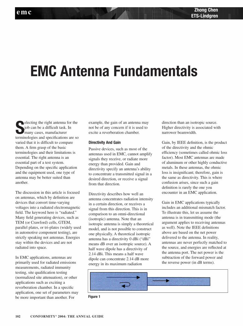
Although it is different from the IEEEdefinition, it is a practical one (this issometimes referred to as apparent gain).For example, an antenna can have avery directive pattern but, if it is notclose to 50 Ω in characteristicimpedance, very small electric fieldlevels will result when connected to a50 Ω source (used for mostinstruments). In most EMCapplications, gains published in theantenna catalogs include this mismatchfactor.
An analogy: water (RF signal) flowsthrough pipes with unequal diameters.Some of the water goes through andsome is reflected (Figure 1).
Reflection Coefficient/VSWR/ReturnLoss
Reflection coefficient, VSWR andreturn loss all describe the samephysical phenomenon as discussed inthe last paragraph, that is, the mismatchfactor. If a mismatch occurs, there is astanding wave established in atransmission line, the voltage ratio ofthe maximum to the minimum is calledvoltage standing wave ratio (VSWR).The closer the VSWR is to unity, thebetter the match is. Reflectioncoefficient is the ratio of the reflectedvoltage to the forward voltage.Reflection coefficient can be a complexnumber, as the reflected voltage doesnot always line up in phase with theforward voltage. The smaller themagnitude of the reflection coefficient,the better the match is. Return loss issimply the magnitude of logarithmicform of the reflection coefficient.
Since all these terms describe the samephysical property, there is a one to onerelationship among them. The simpleequations are,
where is the magnitude of thereflection coefficient, and RL is thereturn loss is dB. In terms of powerrelationship:
where Pnet is the net power, and Pfwd isthe forward power. For example, if anantenna has a VSWR=2:1, themagnitude of the reflection coefficientis 1/3, the return loss is 9.5 dB, and11% of the power is reflected (or 89%net power is delivered to the antenna).
Antenna Factor
Antenna factor (AF) is another practicalterm for EMC engineers, and seldomused outside EMC applications. Itprovides a receiving antenna with therelationship between the incidentelectromagnetic field and the voltage ona 50 Ω load connected to the antenna.In equation form:
where E is the incident electric field,and V is the voltage on the 50 Ω load.AF has a unit of 1/m, or dB m-1.Antennas with smaller AFs are moresensitive to the incident field. It isinteresting to note that AFs generallyincrease with frequency. It comes as nosurprise then that to measure the samefield level, more sensitive receivers areneeded for higher frequencies. AFs arenormally provided by antennamanufactures or calibration labs. Theaccuracy of AFs directly affectsradiated emissions measurement. It isrecommended antennas be calibratedannually to minimize the measurementuncertainties.
Antenna Pattern And Beamwidth
Antenna pattern, in simple terms, is theresponse of an antenna as a function ofviewing angle. In a strict sense, antennapattern is a descriptor for the far fieldresponse. In practice, EMCmeasurements are often performed inthe near field, and antenna pattern istaken quite liberally as well to includenear field responses.
Beamwidth is typically measured whenpower received has fallen half (3 dBdown) of the boresight direction. This iscalled half-power beamwidth or 3 dBbeamwidth. Beamwidth can be used toroughly estimate the size of a uniformfield area in an immunity test. However,many other factors come into play forestablishing uniform field, such asreflection from the ground or walls of achamber. Moreover, patterns could bemeasured at a different distance thanthe one used in the immunity setup,thus the near field effect is different.Beamwidth is not a magic number thatestablishes the size of the uniform fieldplane.
Phase Center
A radiated wavefront has a curvaturewhen in near field. In far field, thecurvature is so large that it can beregarded as a plane wave. The apparentcenter of the curvature is the phasecenter. For many EMC antennas, suchas biconical antennas or dipoles, thephase centers are quite obvious. For logperiodic antennas, the phase centermoves from the back to the front asfrequency goes up. The measurementdistance from the antenna to the deviceunder test is unclear. In practice, acompromise has to be made for thedistance.
Polarization
The polarization of a radiated wave hasto do with the radiated vector fieldtraced out as a function of time. It isbeyond the scope of this article toexplain the full meaning of polarizationin all its detail. Fortunately, many EMCantennas are linearly polarized, such asdipoles, biconical antennas, log periodicdipole arrays, and horns. Linearlypolarized antennas radiate vector fieldin a single direction which is lesscomplicated than other polarizations.Any imperfections are measured by thecross-polarization ratio (the ratio of thefield level in the intended direction tothat of its orthogonal direction). Someantennas are circularly polarized forspecial applications, such as conical logspiral antennas as required by MIL-STD 461.
emc
106 CONFORMITY® 2004: THE ANNUAL GUIDE
Balance
Coaxial cables attached to the antennasare inherently imbalanced, because theyare asymmetrical with respect toground. In other words, the cable shieldto the ground is different from thecenter pin to the ground. Someantennas, such as biconical antennas,employ balun (short for Balanced-to-Unbalanced transformer) to overcomethe imbalance. Basically, a balunprovides low impedance or an easy passthrough to the differential current, andhigh impedance to the common modecurrent. An unbalanced antenna hasdifferent responses depending on whichside is up when polarized vertically. Alarge amount of common mode currentexists between the shield of the feedcable and the ground plane. This causeslarge measurement uncertainties.
Bandwidth
Bandwidth is “the range of frequencieswithin which the performance of theantenna, with respect to somecharacteristic, conforms to a specificstandard” [1]. The definition is quitebroad. It does not explicitly specifywhat the “characteristics” or “specificstandard” are, so the term bandwidth issubjective. Depending on theapplication, the typical characteristicscan include all or some of the termsdiscussed previously. Engineeringjudgments are needed to determinewhat is acceptable for your application.
Typical EMC Antennas
Several types of antennas cansometimes all satisfy the basicrequirements of a measurement. Thefollowing list provides brief features,application notes and possibledrawbacks of the typical EMC antennasto hopefully aid readers in selecting thebest fit.
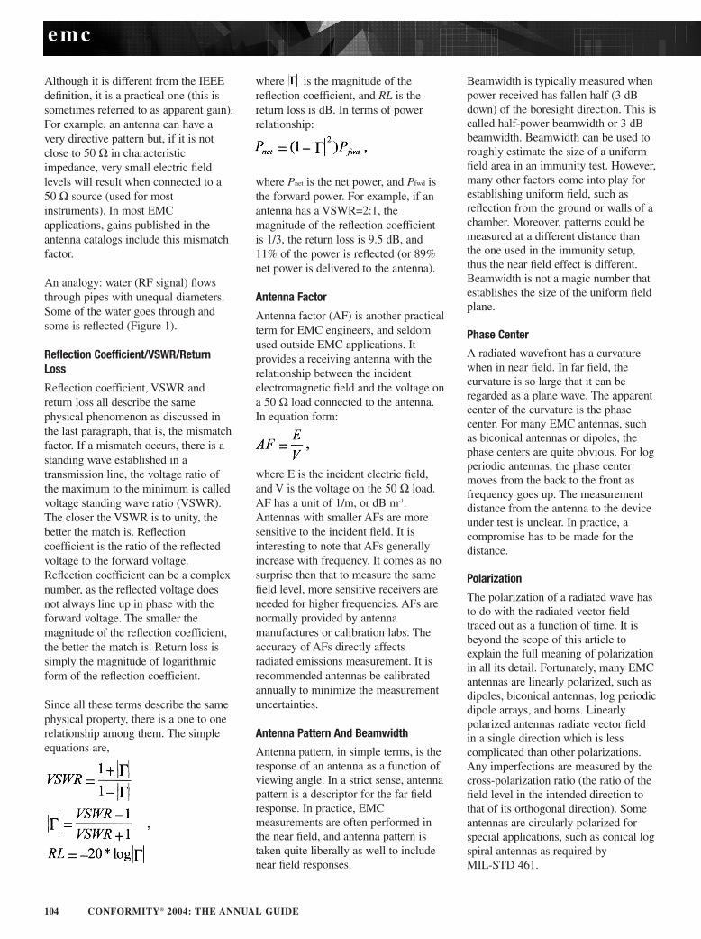
Loop And Magnetic Field CoilTypically used in the frequency rangefrom 20 Hz to 30 MHz for measuringmagnetic fields. At these frequencies,measurements are in effect within thenear field region. Unlike in the far field,
in the near field region, electric fieldsdo not relate to the magnetic field by377 Ω. Magnetic field cannot bederived simply from the electric field.The designs of these antennas ensurethey predominantly produce or respondto magnetic fields.
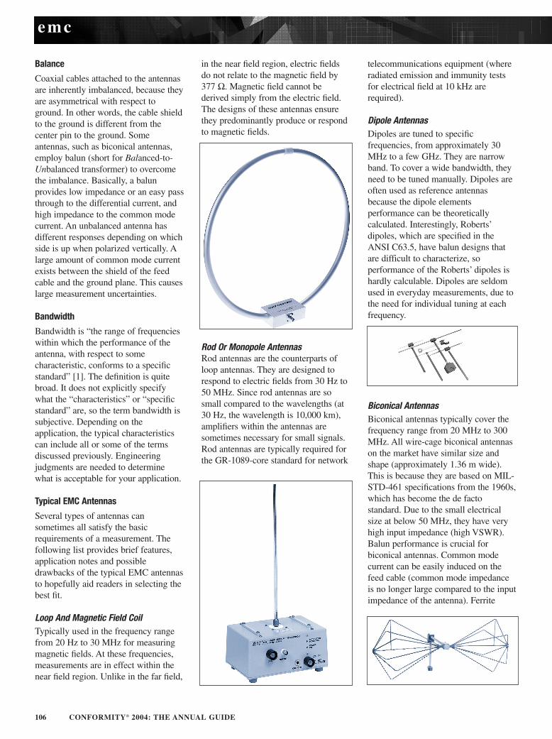
Rod Or Monopole AntennasRod antennas are the counterparts ofloop antennas. They are designed torespond to electric fields from 30 Hz to50 MHz. Since rod antennas are sosmall compared to the wavelengths (at30 Hz, the wavelength is 10,000 km),amplifiers within the antennas aresometimes necessary for small signals.Rod antennas are typically required forthe GR-1089-core standard for network
telecommunications equipment (whereradiated emission and immunity testsfor electrical field at 10 kHz are required).
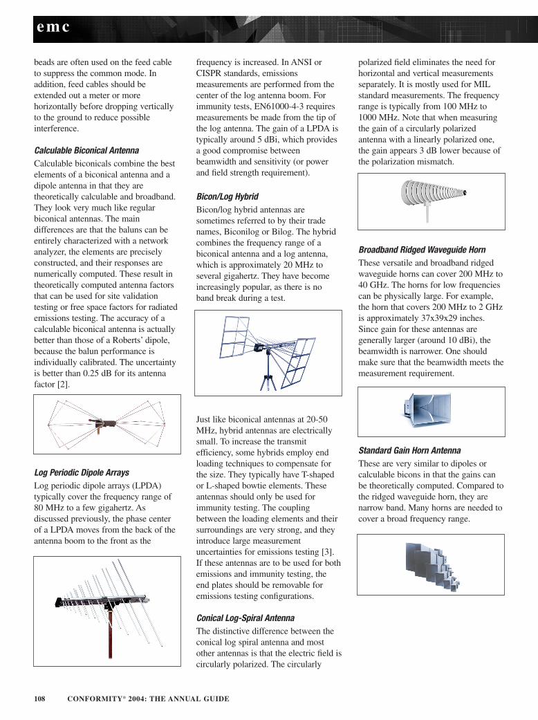
Dipole AntennasDipoles are tuned to specificfrequencies, from approximately 30MHz to a few GHz. They are narrowband. To cover a wide bandwidth, theyneed to be tuned manually. Dipoles areoften used as reference antennasbecause the dipole elementsperformance can be theoreticallycalculated. Interestingly, Roberts’dipoles, which are specified in theANSI C63.5, have balun designs thatare difficult to characterize, soperformance of the Roberts’ dipoles ishardly calculable. Dipoles are seldomused in everyday measurements, due tothe need for individual tuning at eachfrequency.
Biconical Antennas Biconical antennas typically cover thefrequency range from 20 MHz to 300MHz. All wire-cage biconical antennason the market have similar size andshape (approximately 1.36 m wide).This is because they are based on MIL-STD-461 specifications from the 1960s,which has become the de factostandard. Due to the small electricalsize at below 50 MHz, they have veryhigh input impedance (high VSWR).Balun performance is crucial forbiconical antennas. Common modecurrent can be easily induced on thefeed cable (common mode impedanceis no longer large compared to the inputimpedance of the antenna). Ferrite
emc
108 CONFORMITY® 2004: THE ANNUAL GUIDE
beads are often used on the feed cableto suppress the common mode. Inaddition, feed cables should beextended out a meter or morehorizontally before dropping verticallyto the ground to reduce possibleinterference.
Calculable Biconical AntennaCalculable biconicals combine the bestelements of a biconical antenna and adipole antenna in that they aretheoretically calculable and broadband.They look very much like regularbiconical antennas. The maindifferences are that the baluns can beentirely characterized with a networkanalyzer, the elements are preciselyconstructed, and their responses arenumerically computed. These result intheoretically computed antenna factorsthat can be used for site validationtesting or free space factors for radiatedemissions testing. The accuracy of acalculable biconical antenna is actuallybetter than those of a Roberts’ dipole,because the balun performance isindividually calibrated. The uncertaintyis better than 0.25 dB for its antennafactor [2].
Log Periodic Dipole ArraysLog periodic dipole arrays (LPDA)typically cover the frequency range of80 MHz to a few gigahertz. Asdiscussed previously, the phase centerof a LPDA moves from the back of theantenna boom to the front as the
frequency is increased. In ANSI orCISPR standards, emissionsmeasurements are performed from thecenter of the log antenna boom. Forimmunity tests, EN61000-4-3 requiresmeasurements be made from the tip ofthe log antenna. The gain of a LPDA istypically around 5 dBi, which providesa good compromise betweenbeamwidth and sensitivity (or powerand field strength requirement).
Bicon/Log HybridBicon/log hybrid antennas aresometimes referred to by their tradenames, Biconilog or Bilog. The hybridcombines the frequency range of abiconical antenna and a log antenna,which is approximately 20 MHz toseveral gigahertz. They have becomeincreasingly popular, as there is noband break during a test.
Just like biconical antennas at 20-50MHz, hybrid antennas are electricallysmall. To increase the transmitefficiency, some hybrids employ endloading techniques to compensate forthe size. They typically have T-shapedor L-shaped bowtie elements. Theseantennas should only be used forimmunity testing. The couplingbetween the loading elements and theirsurroundings are very strong, and theyintroduce large measurementuncertainties for emissions testing [3].If these antennas are to be used for bothemissions and immunity testing, theend plates should be removable foremissions testing configurations.
Conical Log-Spiral AntennaThe distinctive difference between theconical log spiral antenna and mostother antennas is that the electric field iscircularly polarized. The circularly
polarized field eliminates the need forhorizontal and vertical measurementsseparately. It is mostly used for MILstandard measurements. The frequencyrange is typically from 100 MHz to1000 MHz. Note that when measuringthe gain of a circularly polarizedantenna with a linearly polarized one,the gain appears 3 dB lower because ofthe polarization mismatch.
Broadband Ridged Waveguide HornThese versatile and broadband ridgedwaveguide horns can cover 200 MHz to40 GHz. The horns for low frequenciescan be physically large. For example,the horn that covers 200 MHz to 2 GHzis approximately 37x39x29 inches.Since gain for these antennas aregenerally larger (around 10 dBi), thebeamwidth is narrower. One shouldmake sure that the beamwidth meets themeasurement requirement.
Standard Gain Horn AntennaThese are very similar to dipoles orcalculable bicons in that the gains canbe theoretically computed. Compared tothe ridged waveguide horn, they arenarrow band. Many horns are needed tocover a broad frequency range.
emc
110 CONFORMITY® 2004: THE ANNUAL GUIDE
Antenna Calibrations
There are several methods to calibratean antenna. Much confusion exists forfree-space antenna factors and antennafactors obtained in a specific setup(sometimes called geometry-specificantenna factors). Understanding howAFs are arrived is important inchoosing the right antennas and theirassociated AFs.
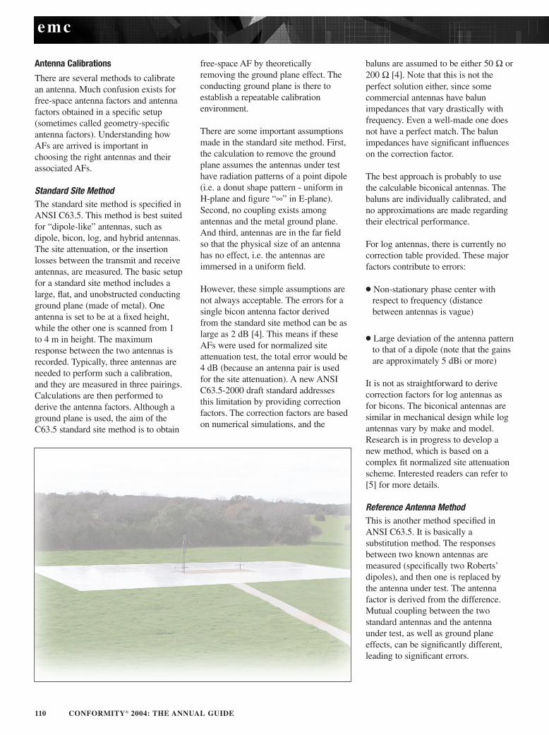
Standard Site MethodThe standard site method is specified inANSI C63.5. This method is best suitedfor “dipole-like” antennas, such asdipole, bicon, log, and hybrid antennas.The site attenuation, or the insertionlosses between the transmit and receiveantennas, are measured. The basic setupfor a standard site method includes alarge, flat, and unobstructed conductingground plane (made of metal). Oneantenna is set to be at a fixed height,while the other one is scanned from 1to 4 m in height. The maximumresponse between the two antennas isrecorded. Typically, three antennas areneeded to perform such a calibration,and they are measured in three pairings.Calculations are then performed toderive the antenna factors. Although aground plane is used, the aim of theC63.5 standard site method is to obtain
free-space AF by theoreticallyremoving the ground plane effect. Theconducting ground plane is there toestablish a repeatable calibrationenvironment.
There are some important assumptionsmade in the standard site method. First,the calculation to remove the groundplane assumes the antennas under testhave radiation patterns of a point dipole(i.e. a donut shape pattern - uniform inH-plane and figure “∞” in E-plane).Second, no coupling exists amongantennas and the metal ground plane.And third, antennas are in the far fieldso that the physical size of an antennahas no effect, i.e. the antennas areimmersed in a uniform field.
However, these simple assumptions arenot always acceptable. The errors for asingle bicon antenna factor derivedfrom the standard site method can be aslarge as 2 dB [4]. This means if theseAFs were used for normalized siteattenuation test, the total error would be4 dB (because an antenna pair is usedfor the site attenuation). A new ANSIC63.5-2000 draft standard addressesthis limitation by providing correctionfactors. The correction factors are basedon numerical simulations, and the
baluns are assumed to be either 50 Ω or200 Ω [4]. Note that this is not theperfect solution either, since somecommercial antennas have balunimpedances that vary drastically withfrequency. Even a well-made one doesnot have a perfect match. The balunimpedances have significant influenceson the correction factor.
The best approach is probably to usethe calculable biconical antennas. Thebaluns are individually calibrated, andno approximations are made regardingtheir electrical performance.
For log antennas, there is currently nocorrection table provided. These majorfactors contribute to errors:
Non-stationary phase center withrespect to frequency (distancebetween antennas is vague)
Large deviation of the antenna patternto that of a dipole (note that the gainsare approximately 5 dBi or more)
It is not as straightforward to derivecorrection factors for log antennas asfor bicons. The biconical antennas aresimilar in mechanical design while logantennas vary by make and model.Research is in progress to develop anew method, which is based on acomplex fit normalized site attenuationscheme. Interested readers can refer to[5] for more details.
Reference Antenna MethodThis is another method specified inANSI C63.5. It is basically asubstitution method. The responsesbetween two known antennas aremeasured (specifically two Roberts’dipoles), and then one is replaced bythe antenna under test. The antennafactor is derived from the difference.Mutual coupling between the twostandard antennas and the antennaunder test, as well as ground planeeffects, can be significantly different,leading to significant errors.
emc
112 CONFORMITY® 2004: THE ANNUAL GUIDE
Other MethodsThere are other calibration methods,such as those used for loop antennasand rod antennas. Some labs usevariations of the ANSI C63.5 method tocalibrate log, dipole and biconantennas, such as standard field method,or standard antenna method withprecision dipoles etc. One importantnote is that, even if a perfect free-spaceantenna factor is obtained, one shouldstill apply the correction factorsprovided by ANSI C63.5 fornormalized site attenuation test. This isbecause normalized site attenuation(NSA) tests are not in free space. Thecorrection factors are used to correct theinfluences from the test setup, i.e. thedifferences between free space and thespecific geometry of an NSA setup.
Calibrations For High Gain AntennasHigh gains, such as horn antennas, havenarrow beamwidth. They do not seeground plane when placed in a close
distance. In that case, the calibration isin free-space condition.
Use Of Antennas For Radiated EmissionsTesting
Radiated emissions tests are defined inANSI C63.4 in the US or the equivalentEN standards in Europe. The test setupis very similar to the antenna calibrationsetup. A large flat, unobstructed metalground plane is used. The equipmentunder test is set on a low dielectrictable, which is 80 cm high. The table isplaced on a turntable, which canprovide a full 360° scan. The receiveantenna is scanned from 1 to 4 m forboth horizontal and verticalpolarization, and the maximumreadings are recorded and compared tothe standards.
For emissions measurements, it isrecommended to use free-space antennafactor. This is despite the fact that themeasurements are not performed in a
free space environment. The trueantenna factors in the specific testenvironment are height dependent. Thefree space AF provides a goodcompromise.
Use Of Antennas For Radiated ImmunityTesting
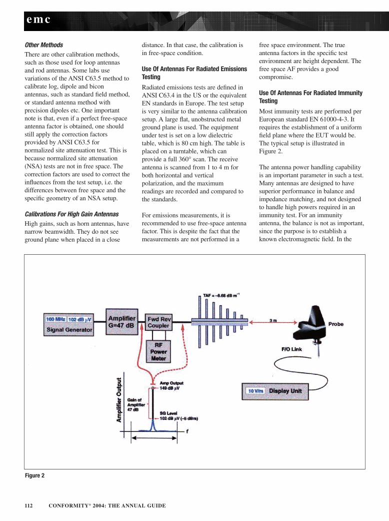
Most immunity tests are performed perEuropean standard EN 61000-4-3. Itrequires the establishment of a uniformfield plane where the EUT would be.The typical setup is illustrated in Figure 2.
The antenna power handling capabilityis an important parameter in such a test.Many antennas are designed to havesuperior performance in balance andimpedance matching, and not designedto handle high powers required in animmunity test. For an immunityantenna, the balance is not as important,since the purpose is to establish aknown electromagnetic field. In the
emc
Figure 2
114 CONFORMITY® 2004: THE ANNUAL GUIDE
setup shown, the isotropic field probe isthe key in setting up a calibrated field.
A field probe is a special kind ofantenna. It consists of three independentbroadband antennas, which are orientedorthogonally. The field levels aremeasured and reported digitally througha fiber optical link to a readout unit or acomputer. The total field is summed asRMS values of the three axes:
A field probe is a broadbandinstrument. If more than one frequencycomponent exist, a field probe respondsto all of them. This is in contrast toantennas connected to a spectrumanalyzer, where the analyzerdiscriminates between frequencies. It isthus critical to ensure the purity of thesignal in an immunity testing setup,especially the harmonic field generatedby a power amplifier.
Just as antenna factors are extremelyimportant for emissions measurement,the calibrations of probe factors arevital for immunity tests. Calibrationlabs typically provide a frequencycorrection table for each probe. Thiscorrects the reading for the specificfrequencies. Another important factor isthe linearity of a probe. This is aparameter that measures how faithful aprobe measures at different field levels.Modern probes have internaladjustments for linearity, making sureprobe readings are correct not only atthe calibration field levels (e.g. 20V/m). Not all probe calibrations areequal. When performing a probecalibration, a simple frequency responsecalibration without re-adjustinglinearity is insufficient in most cases.
Conclusion
A broad range of topics have beendiscussed in this article, including thebasic parameters of antennas, thecommon types of antennas used inEMC, their calibrations andapplications in radiated emissions andimmunity tests. Intentionally left out ofthis article are many detail theoreticaldiscussions, equations and formulas
found in other antenna papers in anattempt to make the points easier tounderstand. This is not meant totrivialize these topics. The reader canrefer to [1,6] for more in-depthexplanations on many importantantenna topics.
References
[1] C. A. Balanis, “Antenna TheoryAnalysis and Design”, SecondEdition, John Wiley & Sons, Inc.,New York, 1997.
[2] Z Chen and A Cook, “LowUncertainty Broadband EMCMeasurement Using CalculablePrecision Biconical Antennas,” 2000IEEE International Symposium onElectromagnetic Compatibility,Washington, DC, 2000.
[3] Zhong Chen, “Understanding themeasurement uncertainties of thebicon/log hybrid antennas”,ITEM 1999.
[4] Z Chen and M Windler, “SystematicErrors in Normalized SiteAttenuation Testing,” ComplianceEngineering 17,no. 1 (2000): 38–48.
[5] Z Chen and MD Foegelle, “AnImproved Method for DeterminingNormalized Site Attenuation UsingLog Periodic Dipole Arrays,” , 2000IEEE International Symposium onElectromagnetic Compatibility,Washington, DC, 2000.
[6] J.D. Kraus, “Antennas”, SecondEdition, McGraw-Hill, 1988.
About The AuthorZhong Chen is a principal designengineer at ETS-Lindgren, and can bereached by e-mail at [email protected].
This article is based on “AntennaFundamentals” tutorial presented atthe IEEE International Symposium onElectromagnetic Compatibilities inMinneapolis, 2002. The author wishesto thank Karen Phillips of ETS-Lindgren for her help composingand designing the presentation and thisarticle, and ETS-Lindgren for theirtotal support.
Go to www.conformity.com/INFODIRECTInput #