em1402 evaluation module - ti.com · delivery: ti delivers ti evaluation boards, kits, or modules,...
TRANSCRIPT
1SNOU143–February 2017Submit Documentation Feedback
Copyright © 2017, Texas Instruments Incorporated
EM1402 Evaluation Module
User's GuideSNOU143–February 2017
EM1402 Evaluation Module
This user's guide describes the general features, theory of operation, hardware setup, and use of theEM1402EVM. Throughout this user's guide, the abbreviations EVM, EM1402EVM, and the term evaluationmodule are synonymous with the EM1402 Evaluation Module, unless otherwise noted. This EVM is anevaluation board of the Active Balance chipset for use in large format Lithium-ion batteries that providesmonitoring, balancing, and communications.
Contents1 EM1402 Evaluation Module ................................................................................................ 22 General Description ......................................................................................................... 3
2.1 Key Features ........................................................................................................ 32.2 Key Electrical Parameters ......................................................................................... 3
3 Theory of Operation ......................................................................................................... 43.1 Single Board......................................................................................................... 63.2 Stacked Systems ................................................................................................... 6
4 Hardware Setup.............................................................................................................. 64.1 Connectors .......................................................................................................... 6
5 EM1402EVM Quick Start Guide.......................................................................................... 105.1 Before You Begin.................................................................................................. 105.2 Hardware Setup ................................................................................................... 115.3 Connecting the Evaluation Modules ............................................................................ 115.4 Software ............................................................................................................ 12
6 Physical Dimensions ....................................................................................................... 136.1 Board Dimensions................................................................................................. 136.2 Board Mounting.................................................................................................... 13
List of Figures
1 System Stack Diagram...................................................................................................... 42 Tyco Electronics 175785-1 (Reference Image Only) ................................................................... 63 Molex 22-12-4062 (Reference Image Only).............................................................................. 74 Tyco Electronics 43045-1601 (Reference Image Only) ................................................................ 85 Tyco Electronics 1452625-1 (Reference Image Only) .................................................................. 96 System Block Diagram .................................................................................................... 117 Dimension Drawing ........................................................................................................ 13
List of Tables
1 Connector Information ...................................................................................................... 62 Pin Description ............................................................................................................... 63 Connector Information ...................................................................................................... 74 Pin Description ............................................................................................................... 75 Connector Information ...................................................................................................... 86 Pin Description ............................................................................................................... 87 Connector Information ...................................................................................................... 98 Pin Description ............................................................................................................... 99 Connections Between EVMs ............................................................................................. 11
EM1402 Evaluation Module www.ti.com
2 SNOU143–February 2017Submit Documentation Feedback
Copyright © 2017, Texas Instruments Incorporated
EM1402 Evaluation Module
TrademarksLaunchPad, Code Composer Studio are trademarks of Texas Instruments.All other trademarks are the property of their respective owners.
1 EM1402 Evaluation ModuleGeneral Texas Instruments High Voltage Evaluation (TI HV EVM) User Safety Guidelines
WARNINGWarning: To minimize risk of fire hazard, always verify and followany specific safety instructions and application considerationsrelated to the batteries being used in conjunction with this EVM.
Always follow TI’s set-up and application instructions, including use of all interface components within theirrecommended electrical rated voltage and power limits. Always use electrical safety precautions to helpensure your personal safety and the safety of those working around you. Contact TI’s Product InformationCenter http://support/ti./com for further information.
Save all warnings and instructions for future reference.Failure to follow warnings and instructions may result in personal injury, property damage, ordeath due to electrical shock and/or burn hazards.The term TI HV EVM refers to an electronic device typically provided as an open framed, unenclosedprinted-circuit-board assembly. It is intended strictly for use in development laboratory environments,solely for qualified professional users having training, expertise, and knowledge of electrical safety risks indevelopment and application of high-voltage electrical circuits. Any other use or application are strictlyprohibited by Texas Instruments. If you are not suitably qualified, you should immediately stop from furtheruse of the HV EVM.1. Work Area Safety:
1. Keep work area clean and orderly.2. Qualified observer(s) must be present any time circuits are energized.3. Effective barriers and signage must be present in the area where the TI HV EVM and its interface
electronics are energized, indicating operation of accessible high voltages may be present, for thepurpose of protecting inadvertent access.
4. All interface circuits, power supplies, evaluation modules, instruments, meters, scopes and otherrelated apparatus used in a development environment exceeding 50 VRMS or 75 VDC must beelectrically located within a protected Emergency Power Off (EPO) protected power strip.
5. Use a stable and non-conductive work surface.6. Use adequately insulated clamps and wires to attach measurement probes and instruments. No
freehand testing whenever possible.2. Electrical Safety:As a precautionary measure, it is always a good engineering practice to assume that
the entire EVM may have fully accessible and active high voltages.1. De-energize the TI HV EVM and all its inputs, outputs, and electrical loads before performing any
electrical or other diagnostic measurements. Revalidate that TI HV EVM power has been safelyde-energized.
2. With the EVM confirmed de-energized, proceed with required electrical circuit configurations,wiring, measurement equipment hook-ups and other application needs, while still assuming theEVM circuit and measuring instruments are electrically live.
3. Once EVM readiness is complete, energize the EVM as intended.

www.ti.com General Description
3SNOU143–February 2017Submit Documentation Feedback
Copyright © 2017, Texas Instruments Incorporated
EM1402 Evaluation Module
WARNING: while the EVM is energized, never touch the EVM or its electrical circuits as theycould be at high voltages capable of causing electrical shock hazard.
3. Personal Safety:1. Wear personal protective equipment, for example, latex gloves or safety glasses with side shields
or protect EVM in an adequate lucent plastic box with interlocks from accidental touch.4. Limitation for Safe Use:
1. EVMs are not to be used as all or part of a production unit.
2 General DescriptionThe Texas Instruments EM1402EVM Battery Management System (BMS) is an evaluation board of theActive Balance chipset for use in large format Lithium-ion batteries that provides monitoring, balancing,and communications. With precise and robust active balancing, the Active Balance BMS is capable of bi-directional power transfer at each cell. Each EM1402EVM can manage 6 to 16 cells (70-V max) for Li-ionbattery applications. The EM1402EVM modules can be stacked up to 1300 V. The system provides fastcell balancing, diagnostics, and module to controller communication. Independent protection circuitry isalso provided.
The EM1402EVM is equipped with precision measurement and synchronous communication to enable amaster controller to perform State of Charge (SOC) and State of Health (SOH) estimation. Highly accuratecell voltages and a fast sampling time for the entire battery pack allows more efficient operation of batterymodules and more accurate SOC and SOH calculations. The user will be able to extend the availablecapacity of the battery and will benefit from longer pack lifetimes versus passive or dissipative balancingsystems.
The EM1402EVM is equipped with smart diagnostic systems. These systems monitor fault events such asundervoltage, overvoltage, and overtemperature. The system is also capable of pack temperature and celltemperature sensing. The fault flagging systems help protect the battery module and alert the user ofpotential problems.
2.1 Key FeaturesThis EVM includes the following features:• Active bi-directional cell balancing• Multi-cell charge and discharge capability• Isolated communications (5 kV)• Flexible architecture for up to 16 cells• UART interface• High accuracy cell voltage measurement• Diagnostics
2.2 Key Electrical ParametersThe following table identifies the key electrical parameters:
Maximum battery pack voltage 1300 VMaximum operating voltage 70 VMinimum operating voltage 12 VMaximum cell open circuit voltage 5VAmbient temperature -40 ºC to 85 ºCNominal operating temperature -20 ºC to 60 ºCCell balancing current up to +/- 5 A
-+
-+
-+
Sw
itch
Mat
rix
8
7
1
-+16
Diff
eren
tial
MU
X
ADC
1
16
Vtop
1
16
GPIO
Sw
itch
Mat
rix
3
± 5 A (max)
9
1
Active Cell Balancing (3x EMB1428Q + EMB1499Q)
Cell Fault Detection
Cell Monitoring (Voltage)
Power Supplies12V
5.3V
Cel
l Mod
ule
1C
ell M
odul
e n
Pack +
Pack -
BMS Module 1 UART TX/RX
WAKEUP
BMS Module 2
Cell Module
2
+-
+-
OV
UV
7
+-
OT
IC Temp12
7
Remote Temp Inputs
MicrocontrollerFAULT_N
COMM bus
FAULT bus
MU
X
bq76PL455A-Q1 Monitor + Protector
2
Sw
itch
Mat
rix
10
16 SPI
Daisy-Chain
Comms
Isolated 12V
BMS Module 1
Isolated 12V
VP Regulator
Daisy-Chain
Comms
12VF
COMM bus
FAULT bus
Copyright © 2017, Texas Instruments Incorporated
Theory of Operation www.ti.com
4 SNOU143–February 2017Submit Documentation Feedback
Copyright © 2017, Texas Instruments Incorporated
EM1402 Evaluation Module
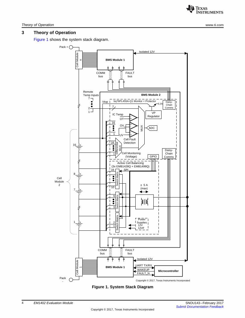
3 Theory of OperationFigure 1 shows the system stack diagram.
Figure 1. System Stack Diagram
www.ti.com Theory of Operation
5SNOU143–February 2017Submit Documentation Feedback
Copyright © 2017, Texas Instruments Incorporated
EM1402 Evaluation Module
The BMS system is designed to prolong the useful life of Lithium-ion cells in battery packs through activebalancing. The battery pack is broken into a series of modules, each of which contains up to 16 cells. Thissystem will monitor voltages of individual battery cells and transfer charge from the module stack to anunder-charged cell or take charge from an over-charged cell and transfer it to the module stack. The BMSallows battery powered electric machines to use smaller battery packs and use fewer charging cycles toperform the same amount of work. It also improves the overall lifetime of Li-ion battery packs bypreventing under- and overvoltage damage from occurring.
The BMS system has three main sub-systems, as shown in Figure 1:• Cell voltage monitoring circuitry• Cell fault detection• Active cell balancing engine
The cell-monitoring architecture is based on the bq76PL455A-Q1 (16 cell monitor and protection). EachEMB1428Q is designed to control access to up to 7 cells of a typical 16-cell battery module; the full 16-cellmodule utilizes three EMB1428Q and one to three EMB1499Q ICs. The EM1402EVM is designed withone EMB1499Q IC to allow simultaneous charge and discharge of a single cell (of the up to 16 cellsattached) at up to 5 A.
All commands and data are communicated with a host via either a UART or daisy-chain communicationconnection. The EM1402 will not do anything without being first commanded from the host. The EM1402can support a host PC or microcontroller (via the UART connection header) or a daisy-chain interface froma bq76PL455A-Q1 implemented as a communication bridge. The EMB1428Q is controlled via an SPIinterface implemented on the bq76PL455A-Q1 GPIO.
The EM1402EVM has three EMB1428Q devices sharing control of a single EMB1499Q bi-directional DC-DC converter. The EM1402EVM has connected the cells the EMB1428Q devices as follows:• EMB1428Q 1 (U2) : cells 1 and 2• EMB1428Q 2 (U3) : cells 3 to 9• EMB1428Q 3 (U4) : cells 10 to 16
The typical flow is for the host to go through the following sequence:1. Wakeup the EM1402 board by sending a WAKEUP pulse when using the UART interface, or sending
a WAKE tone when using the EM1402 in a stack of other EM1402 boards for a large battery pack or abq76PL455A-Q1 configured as a bridge. Initialize the bq76PL455A-Q1 to be ready for use.
2. Send a sample command to the bq76PL455A-Q1 to read the cell measurement results.3. The host will use the cell measurement data to calculate an average and determine the highest or
lowest cells and determine the one cell that should be charged or discharged.4. Send commands to the bq76PL455A-Q1 to initialize the EMB1428Q communication interface on the
bq76PL455A-Q1 GPIO.5. Send commands to the bq76PL455A-Q1 to initialize the SN74AHC595Q I/O expander to enable the
chip select for the 8-bit DAC on the EM1402EVM.6. Send commands to the bq76PL455A-Q1 to initialize the 8-bit DAC on the EM1402EVM which is used
to set the charge or discharge current level (an input to EMB1499Q).7. Send commands to the bq76PL455A-Q1 to initialize the SN74AHC595Q I/O expander to enable the
chip select for the EMB1428Q connected to the target cell (determined in step 3).8. Send commands to the bq76PL455A-Q1 to send the start command to the EMB1428Q to charge or
discharge the target cell.9. When charge or discharge is to be stopped, send commands to the bq76PL455A-Q1 to send the stop
command to the EMB1428Q to stop the charge or discharge of the target cell.• If no stop command is sent, the EMB1499Q has a built-in timeout of 8 seconds, after which time
the charge or discharge will be stopped automatically.• If a longer amount of charge or discharge time is needed, the host will need to send a stop
command, followed by a start command at least every <8 seconds.10. The host can then decide to repeat the process (back to step 2) or send commands to shutdown the
EM1402EVM and return later.
Theory of Operation www.ti.com
6 SNOU143–February 2017Submit Documentation Feedback
Copyright © 2017, Texas Instruments Incorporated
EM1402 Evaluation Module
3.1 Single BoardAs a single board the BMS can actively balance up to 16 cells up to 70 V of total voltage. Communicationto the EM1402EVM is handled by the daisy-chain communications bus from another bq76PL455A-Q1 orthe UART host interface.
3.2 Stacked SystemsThe BMS boards may be stacked up to 1300 V. Communication to the EM1402EVM is handled by thedaisy-chain communications bus from another bq76PL455A-Q1.
4 Hardware Setup
4.1 Connectors
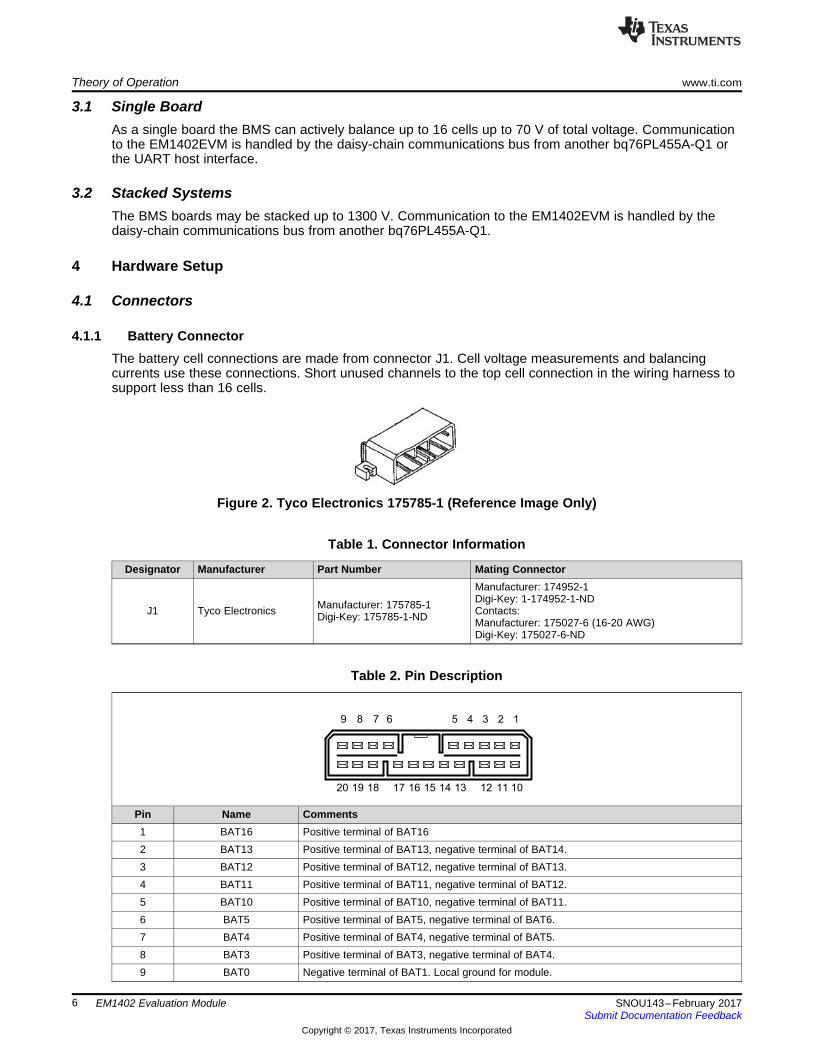
4.1.1 Battery ConnectorThe battery cell connections are made from connector J1. Cell voltage measurements and balancingcurrents use these connections. Short unused channels to the top cell connection in the wiring harness tosupport less than 16 cells.
Figure 2. Tyco Electronics 175785-1 (Reference Image Only)
Table 1. Connector Information
Designator Manufacturer Part Number Mating Connector
J1 Tyco Electronics Manufacturer: 175785-1Digi-Key: 175785-1-ND
Manufacturer: 174952-1Digi-Key: 1-174952-1-NDContacts:Manufacturer: 175027-6 (16-20 AWG)Digi-Key: 175027-6-ND
Table 2. Pin Description
Pin Name Comments1 BAT16 Positive terminal of BAT162 BAT13 Positive terminal of BAT13, negative terminal of BAT14.3 BAT12 Positive terminal of BAT12, negative terminal of BAT13.4 BAT11 Positive terminal of BAT11, negative terminal of BAT12.5 BAT10 Positive terminal of BAT10, negative terminal of BAT11.6 BAT5 Positive terminal of BAT5, negative terminal of BAT6.7 BAT4 Positive terminal of BAT4, negative terminal of BAT5.8 BAT3 Positive terminal of BAT3, negative terminal of BAT4.9 BAT0 Negative terminal of BAT1. Local ground for module.
1 6
www.ti.com Hardware Setup
7SNOU143–February 2017Submit Documentation Feedback
Copyright © 2017, Texas Instruments Incorporated
EM1402 Evaluation Module
Table 2. Pin Description (continued)10 BAT15 Positive terminal of BAT16, negative terminal of BAT16.11 BAT0 Negative terminal of BAT1. Local ground for module.12 BAT14 Positive terminal of BAT14, negative terminal of BAT15.13 NC Not connected14 BAT9 Positive terminal of BAT9, negative terminal of BAT10.15 BAT8 Positive terminal of BAT8, negative terminal of BAT9.16 BAT7 Positive terminal of BAT7, negative terminal of BAT8.17 BAT6 Positive terminal of BAT6, negative terminal of BAT7.18 BAT1 Positive terminal of BAT1, negative terminal of BAT2.19 BAT16 Positive terminal of BAT1620 BAT2 Positive terminal of BAT2, negative terminal of BAT3.
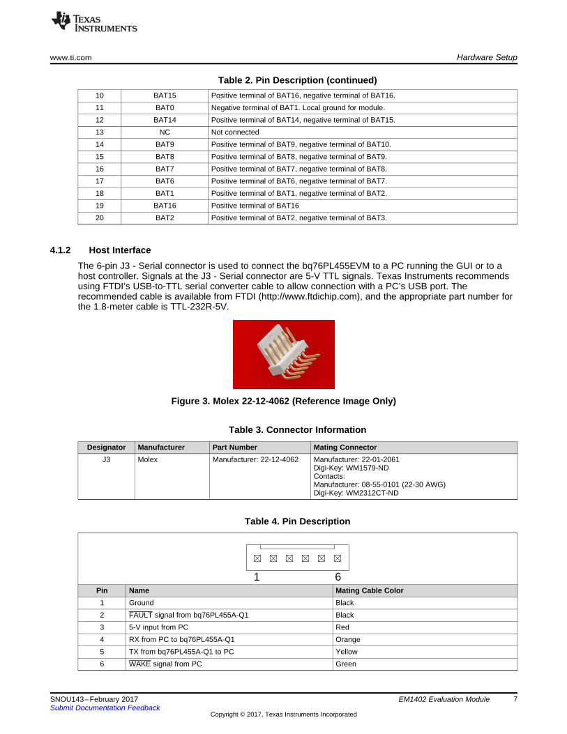
4.1.2 Host InterfaceThe 6-pin J3 - Serial connector is used to connect the bq76PL455EVM to a PC running the GUI or to ahost controller. Signals at the J3 - Serial connector are 5-V TTL signals. Texas Instruments recommendsusing FTDI’s USB-to-TTL serial converter cable to allow connection with a PC’s USB port. Therecommended cable is available from FTDI (http://www.ftdichip.com), and the appropriate part number forthe 1.8-meter cable is TTL-232R-5V.
Figure 3. Molex 22-12-4062 (Reference Image Only)
Table 3. Connector Information
Designator Manufacturer Part Number Mating ConnectorJ3 Molex Manufacturer: 22-12-4062 Manufacturer: 22-01-2061
Digi-Key: WM1579-NDContacts:Manufacturer: 08-55-0101 (22-30 AWG)Digi-Key: WM2312CT-ND
Table 4. Pin Description
Pin Name Mating Cable Color1 Ground Black2 FAULT signal from bq76PL455A-Q1 Black3 5-V input from PC Red4 RX from PC to bq76PL455A-Q1 Orange5 TX from bq76PL455A-Q1 to PC Yellow6 WAKE signal from PC Green
Hardware Setup www.ti.com
8 SNOU143–February 2017Submit Documentation Feedback
Copyright © 2017, Texas Instruments Incorporated
EM1402 Evaluation Module
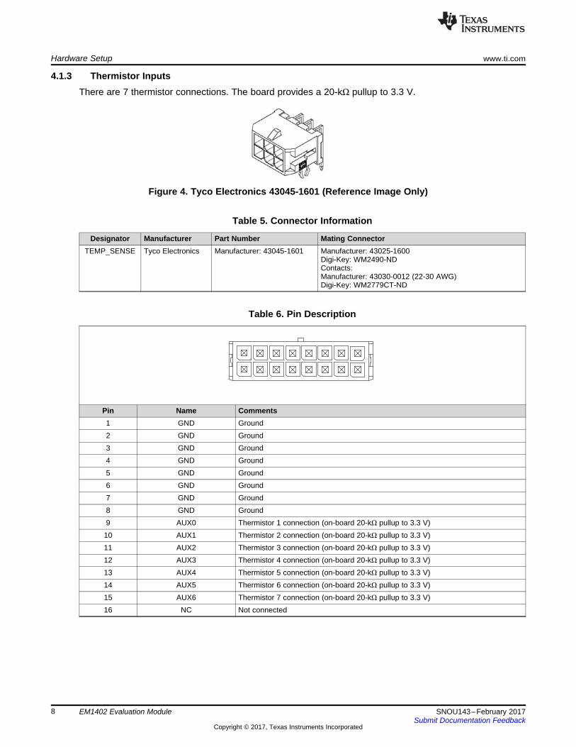
4.1.3 Thermistor InputsThere are 7 thermistor connections. The board provides a 20-kΩ pullup to 3.3 V.
Figure 4. Tyco Electronics 43045-1601 (Reference Image Only)
Table 5. Connector Information
Designator Manufacturer Part Number Mating ConnectorTEMP_SENSE Tyco Electronics Manufacturer: 43045-1601 Manufacturer: 43025-1600
Digi-Key: WM2490-NDContacts:Manufacturer: 43030-0012 (22-30 AWG)Digi-Key: WM2779CT-ND
Table 6. Pin Description
Pin Name Comments1 GND Ground2 GND Ground3 GND Ground4 GND Ground5 GND Ground6 GND Ground7 GND Ground8 GND Ground9 AUX0 Thermistor 1 connection (on-board 20-kΩ pullup to 3.3 V)10 AUX1 Thermistor 2 connection (on-board 20-kΩ pullup to 3.3 V)11 AUX2 Thermistor 3 connection (on-board 20-kΩ pullup to 3.3 V)12 AUX3 Thermistor 4 connection (on-board 20-kΩ pullup to 3.3 V)13 AUX4 Thermistor 5 connection (on-board 20-kΩ pullup to 3.3 V)14 AUX5 Thermistor 6 connection (on-board 20-kΩ pullup to 3.3 V)15 AUX6 Thermistor 7 connection (on-board 20-kΩ pullup to 3.3 V)16 NC Not connected
www.ti.com Hardware Setup
9SNOU143–February 2017Submit Documentation Feedback
Copyright © 2017, Texas Instruments Incorporated
EM1402 Evaluation Module
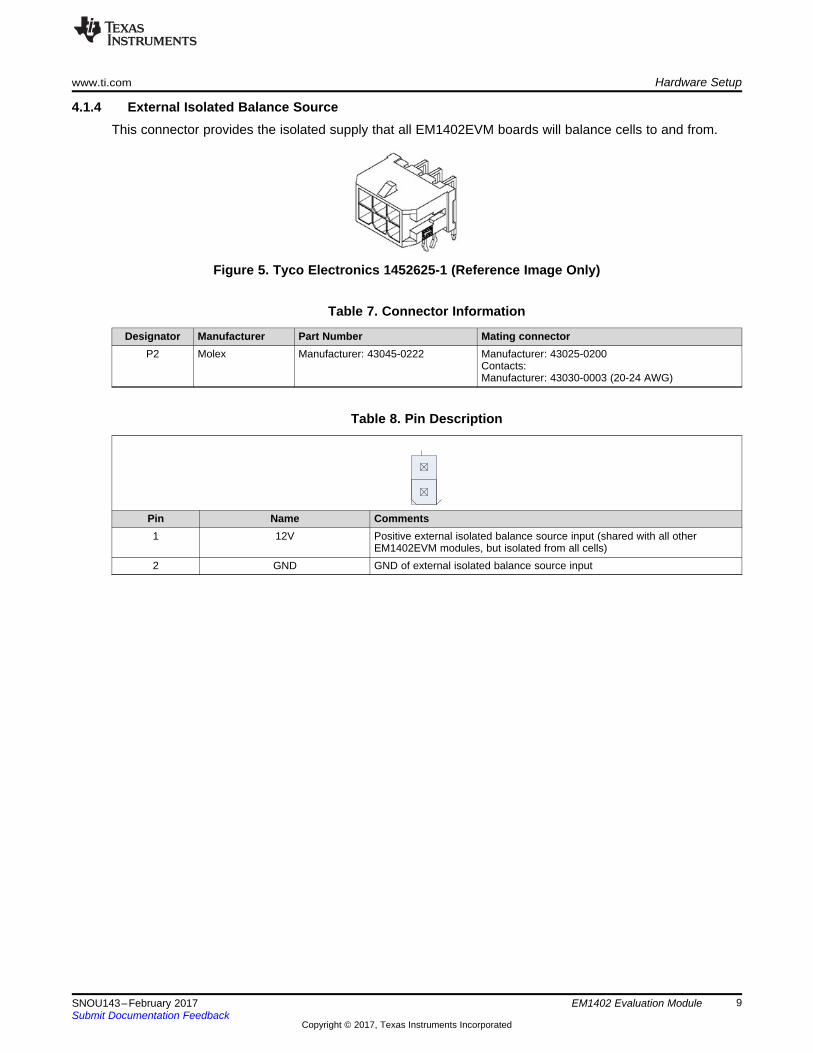
4.1.4 External Isolated Balance SourceThis connector provides the isolated supply that all EM1402EVM boards will balance cells to and from.
Figure 5. Tyco Electronics 1452625-1 (Reference Image Only)
Table 7. Connector Information
Designator Manufacturer Part Number Mating connectorP2 Molex Manufacturer: 43045-0222 Manufacturer: 43025-0200
Contacts:Manufacturer: 43030-0003 (20-24 AWG)
Table 8. Pin Description
Pin Name Comments1 12V Positive external isolated balance source input (shared with all other
EM1402EVM modules, but isolated from all cells)2 GND GND of external isolated balance source input
!
EM1402EVM Quick Start Guide www.ti.com
10 SNOU143–February 2017Submit Documentation Feedback
Copyright © 2017, Texas Instruments Incorporated
EM1402 Evaluation Module
5 EM1402EVM Quick Start Guide
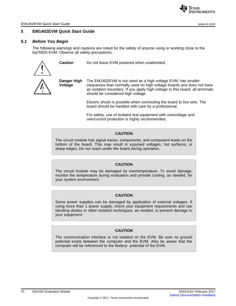
5.1 Before You BeginThe following warnings and cautions are noted for the safety of anyone using or working close to thebq76920 EVM. Observe all safety precautions.
Caution Do not leave EVM powered when unattended.
Danger HighVoltage
The EM1402EVM is not rated as a high voltage EVM, has smallerclearances than normally used on high voltage boards and does not havean isolation boundary. If you apply high voltage to this board, all terminalsshould be considered high voltage.spacerElectric shock is possible when connecting the board to live wire. Theboard should be handled with care by a professional.spacerFor safety, use of isolated test equipment with overvoltage andovercurrent protection is highly recommended.
CAUTIONThe circuit module has signal traces, components, and component leads on thebottom of the board. This may result in exposed voltages, hot surfaces, orsharp edges. Do not reach under the board during operation.
CAUTIONThe circuit module may be damaged by overtemperature. To avoid damage,monitor the temperature during evaluation and provide cooling, as needed, foryour system environment.
CAUTIONSome power supplies can be damaged by application of external voltages. Ifusing more than 1 power supply, check your equipment requirements and useblocking diodes or other isolation techniques, as needed, to prevent damage toyour equipment.
CAUTIONThe communication interface is not isolated on the EVM. Be sure no groundpotential exists between the computer and the EVM. Also be aware that thecomputer will be referenced to the Battery- potential of the EVM.
-+
-+
-+
-+
-+
-+
-+
Charge Flow
Switch Matrix
Cell Balancing Engine
CellÎModuleModuleÎCell
.
.
.
EMB1499Q PWM Controller
Switch Matrix
1
of
7
1
of
2
SPI4
SPI4
12/24 V
.
.
.
UART2
MCU (Optional) SPI
3
-+
-+
-+
-+
bq76PL455A-Q1 (Monitor & Protector)
Switch Matrix
EMB1428Q Gate Controller
1
of
7
SPI4
-+
UART
CS3
ISO GATE Driver
Isolated Bi-Directional
DC-DC
EM1402EVM
Copyright © 2017, Texas Instruments Incorporated
www.ti.com EM1402EVM Quick Start Guide
11SNOU143–February 2017Submit Documentation Feedback
Copyright © 2017, Texas Instruments Incorporated
EM1402 Evaluation Module
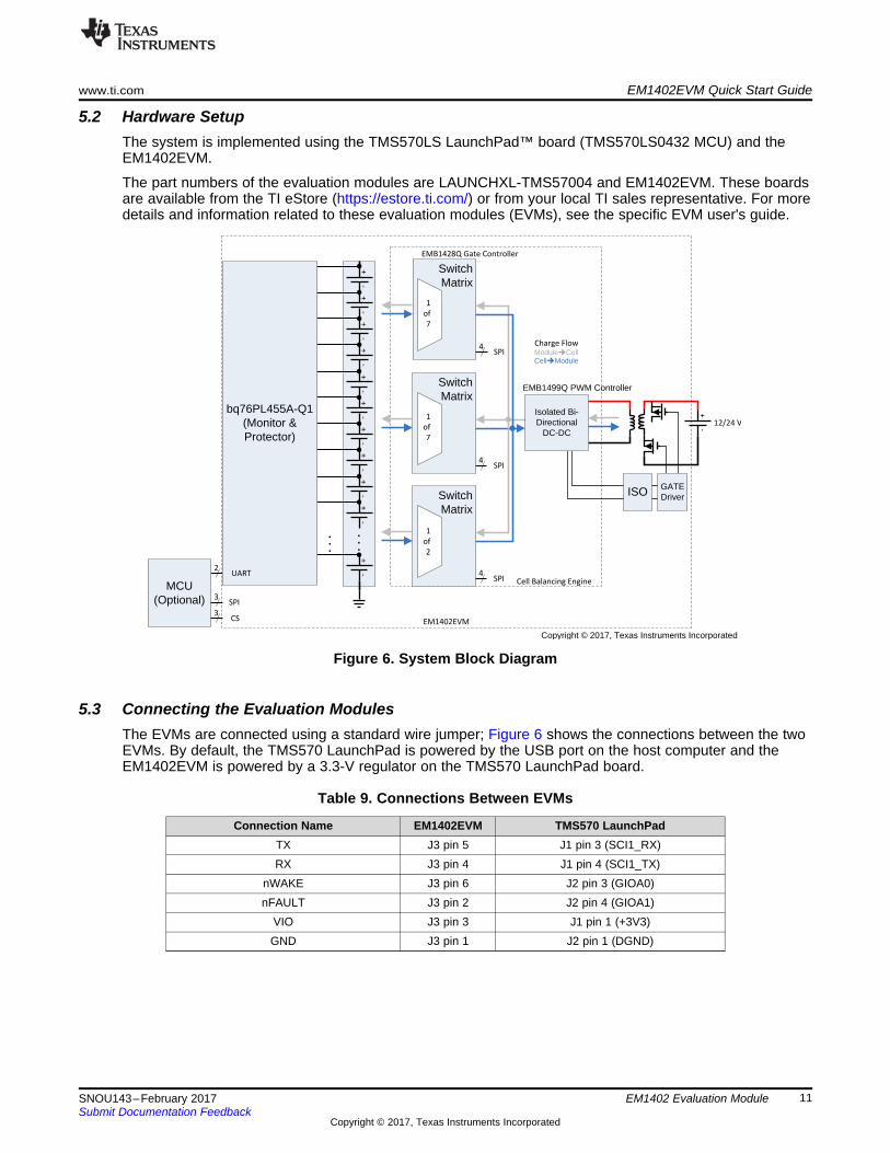
5.2 Hardware SetupThe system is implemented using the TMS570LS LaunchPad™ board (TMS570LS0432 MCU) and theEM1402EVM.
The part numbers of the evaluation modules are LAUNCHXL-TMS57004 and EM1402EVM. These boardsare available from the TI eStore (https://estore.ti.com/) or from your local TI sales representative. For moredetails and information related to these evaluation modules (EVMs), see the specific EVM user's guide.
Figure 6. System Block Diagram
5.3 Connecting the Evaluation ModulesThe EVMs are connected using a standard wire jumper; Figure 6 shows the connections between the twoEVMs. By default, the TMS570 LaunchPad is powered by the USB port on the host computer and theEM1402EVM is powered by a 3.3-V regulator on the TMS570 LaunchPad board.
Table 9. Connections Between EVMs
Connection Name EM1402EVM TMS570 LaunchPadTX J3 pin 5 J1 pin 3 (SCI1_RX)RX J3 pin 4 J1 pin 4 (SCI1_TX)
nWAKE J3 pin 6 J2 pin 3 (GIOA0)nFAULT J3 pin 2 J2 pin 4 (GIOA1)
VIO J3 pin 3 J1 pin 1 (+3V3)GND J3 pin 1 J2 pin 1 (DGND)
EM1402EVM Quick Start Guide www.ti.com
12 SNOU143–February 2017Submit Documentation Feedback
Copyright © 2017, Texas Instruments Incorporated
EM1402 Evaluation Module
5.4 SoftwareThe software provides command API and drivers that implement the examples provided in bq76PL455A-Q1 Software Design Reference (SLVA617). There are comments in the source code that explain thesection in the bq76PL455A-Q1 Software Design Reference document the example refers to.
The example code only provides a control interface to the bq76PL455A-Q1 and does not provide anyother communications interface to the outside world. The customer is expected to develop their owncommunication implementation. Examples of communications interfaces available to the TMS570 are SPI,CAN, or UART.
This firmware provided with this application note provides source code examples of the commandsequences described in the bq76PL455A-Q1 Software Design Reference (SLVA617).
Download sample application code and other information associated with this application report fromtidcci7.
Importing a project into Code Composer Studio™1. Launch the provided file: EM1402EVM Example Code 0.1 Installer.exe and extract files to the default
path provided (C:\ti\EM1402EVM Example Code 0.1).2. Launch Code Composer Studio (CCS):
Start → Programs → Texas Instruments → Code Composer Studio v7 → Code ComposerStudio v7
3. When it launches, CCS requests a workspace is selected, choose “C:\myWorkspace”. Once CCSloads, go to:File → Import → Code Composer Studio → Existing CCS Eclipse Projects
4. In Select search-directory, browse to the folder:C:\ti\EM1402EVM Example Code 0.1
5. In Discovered projects: Check EM1402EVM Example Code
www.ti.com Physical Dimensions
13SNOU143–February 2017Submit Documentation Feedback
Copyright © 2017, Texas Instruments Incorporated
EM1402 Evaluation Module
6 Physical Dimensions
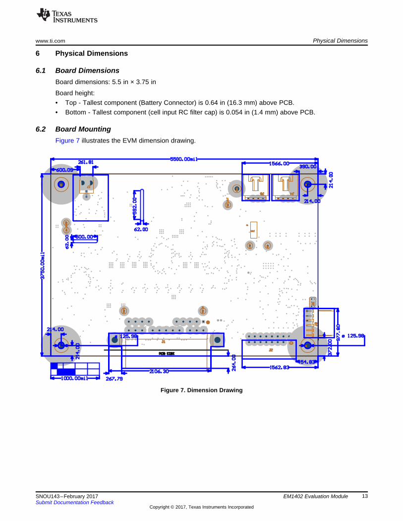
6.1 Board DimensionsBoard dimensions: 5.5 in × 3.75 in
Board height:• Top - Tallest component (Battery Connector) is 0.64 in (16.3 mm) above PCB.• Bottom - Tallest component (cell input RC filter cap) is 0.054 in (1.4 mm) above PCB.
6.2 Board MountingFigure 7 illustrates the EVM dimension drawing.
Figure 7. Dimension Drawing

IMPORTANT NOTICE FOR TI DESIGN INFORMATION AND RESOURCES
Texas Instruments Incorporated (‘TI”) technical, application or other design advice, services or information, including, but not limited to,reference designs and materials relating to evaluation modules, (collectively, “TI Resources”) are intended to assist designers who aredeveloping applications that incorporate TI products; by downloading, accessing or using any particular TI Resource in any way, you(individually or, if you are acting on behalf of a company, your company) agree to use it solely for this purpose and subject to the terms ofthis Notice.TI’s provision of TI Resources does not expand or otherwise alter TI’s applicable published warranties or warranty disclaimers for TIproducts, and no additional obligations or liabilities arise from TI providing such TI Resources. TI reserves the right to make corrections,enhancements, improvements and other changes to its TI Resources.You understand and agree that you remain responsible for using your independent analysis, evaluation and judgment in designing yourapplications and that you have full and exclusive responsibility to assure the safety of your applications and compliance of your applications(and of all TI products used in or for your applications) with all applicable regulations, laws and other applicable requirements. Yourepresent that, with respect to your applications, you have all the necessary expertise to create and implement safeguards that (1)anticipate dangerous consequences of failures, (2) monitor failures and their consequences, and (3) lessen the likelihood of failures thatmight cause harm and take appropriate actions. You agree that prior to using or distributing any applications that include TI products, youwill thoroughly test such applications and the functionality of such TI products as used in such applications. TI has not conducted anytesting other than that specifically described in the published documentation for a particular TI Resource.You are authorized to use, copy and modify any individual TI Resource only in connection with the development of applications that includethe TI product(s) identified in such TI Resource. NO OTHER LICENSE, EXPRESS OR IMPLIED, BY ESTOPPEL OR OTHERWISE TOANY OTHER TI INTELLECTUAL PROPERTY RIGHT, AND NO LICENSE TO ANY TECHNOLOGY OR INTELLECTUAL PROPERTYRIGHT OF TI OR ANY THIRD PARTY IS GRANTED HEREIN, including but not limited to any patent right, copyright, mask work right, orother intellectual property right relating to any combination, machine, or process in which TI products or services are used. Informationregarding or referencing third-party products or services does not constitute a license to use such products or services, or a warranty orendorsement thereof. Use of TI Resources may require a license from a third party under the patents or other intellectual property of thethird party, or a license from TI under the patents or other intellectual property of TI.TI RESOURCES ARE PROVIDED “AS IS” AND WITH ALL FAULTS. TI DISCLAIMS ALL OTHER WARRANTIES ORREPRESENTATIONS, EXPRESS OR IMPLIED, REGARDING TI RESOURCES OR USE THEREOF, INCLUDING BUT NOT LIMITED TOACCURACY OR COMPLETENESS, TITLE, ANY EPIDEMIC FAILURE WARRANTY AND ANY IMPLIED WARRANTIES OFMERCHANTABILITY, FITNESS FOR A PARTICULAR PURPOSE, AND NON-INFRINGEMENT OF ANY THIRD PARTY INTELLECTUALPROPERTY RIGHTS.TI SHALL NOT BE LIABLE FOR AND SHALL NOT DEFEND OR INDEMNIFY YOU AGAINST ANY CLAIM, INCLUDING BUT NOTLIMITED TO ANY INFRINGEMENT CLAIM THAT RELATES TO OR IS BASED ON ANY COMBINATION OF PRODUCTS EVEN IFDESCRIBED IN TI RESOURCES OR OTHERWISE. IN NO EVENT SHALL TI BE LIABLE FOR ANY ACTUAL, DIRECT, SPECIAL,COLLATERAL, INDIRECT, PUNITIVE, INCIDENTAL, CONSEQUENTIAL OR EXEMPLARY DAMAGES IN CONNECTION WITH ORARISING OUT OF TI RESOURCES OR USE THEREOF, AND REGARDLESS OF WHETHER TI HAS BEEN ADVISED OF THEPOSSIBILITY OF SUCH DAMAGES.You agree to fully indemnify TI and its representatives against any damages, costs, losses, and/or liabilities arising out of your non-compliance with the terms and provisions of this Notice.This Notice applies to TI Resources. Additional terms apply to the use and purchase of certain types of materials, TI products and services.These include; without limitation, TI’s standard terms for semiconductor products http://www.ti.com/sc/docs/stdterms.htm), evaluationmodules, and samples (http://www.ti.com/sc/docs/sampterms.htm).
Mailing Address: Texas Instruments, Post Office Box 655303, Dallas, Texas 75265Copyright © 2018, Texas Instruments Incorporated