em 2040 multibeam echo sounder - shipserv · systemoverview systemoverview keyfacts •...
TRANSCRIPT
Product description
EM 2040
Multibeam Echo Sounder

Kongsberg EM 2040Multibeam echo sounder
Product Description
344245/DFebruary 2012 © Kongsberg Maritime AS
Revision status
Document number:344245 / Current revision: D
Rev.A June 2010 First version.
Rev.B February 2011 Overall revision.
Rev.C March 2011 Updated coverage curves
Rev. D February 2012 Overall revision
Copyright©2012 Kongsberg Maritime ASThe information contained in this document remains the sole property of Kongsberg Maritime AS. No partof this document may be copied or reproduced in any form or by any means, and the information containedwithin it is not to be communicated to a third party, without the prior written consent of KongsbergMaritime AS. The document, or any part of it, may not be translated to any other language without thewritten approval from Kongsberg Maritime AS.
DisclaimerKongsberg Maritime AS endeavours to ensure that all information in this document is correct and fairlystated, but does not accept liability for any errors or omissions.
WarningThe equipment to which this manual applies must only be used for the purpose for which it wasdesigned. Improper use or maintenance may cause damage to the equipment and/or injuryto personnel. All users must be familiar with the contents of the appropriate manuals beforeattempting to install, operate, maintain or in any other way work on the equipment.Kongsberg Maritime AS disclaims any responsibility for damage or injury caused by improperinstallation, use or maintenance of the equipment.
Support informationIf you require maintenance or repair, contact one of our offices, distributors or dealers. You can also contactus using the following address: [email protected]. If you need information aboutour other products, visit http://www.km.kongsberg.com.See also Support information on page 44.
Kongsberg Maritime ASwww.kongsberg.com
Product Description
Table of contents
SYSTEM OVERVIEW .......................................................... 5Key facts...................................................................................................................5System characteristics ..............................................................................................7System drawing ......................................................................................................11PERFORMANCE................................................................ 12EM 2040 swath width calculations ........................................................................12
Attenuation curves ...................................................................................... 12Coverage curves ......................................................................................... 13
Depth accuracy .......................................................................................................21Measured standard deviation ....................................................................... 22Horizontal resolution................................................................................... 23
EM 2040 object detection capability......................................................................27INSTALLATION PRINCIPALS........................................... 31Operator station .....................................................................................................31Processing units ......................................................................................................31Transducer array installation ..................................................................................31Subsea vehicle installation .....................................................................................33OPERATIONAL PRINCIPALS............................................ 35System features.......................................................................................................35Seafloor Information System — SIS ......................................................................35Graphical user interface..........................................................................................38Data logging ...........................................................................................................39POST-PROCESSING......................................................... 41Post-processing options..........................................................................................41Caris HIPS/SIPS post-processing...........................................................................41QPS Fledermaus interactive 3D visualization........................................................41Geocap Seafloor .....................................................................................................42HYPACK................................................................................................................42CUSTOMER SUPPORT ...................................................... 43Introduction ............................................................................................................43Installation ..............................................................................................................43Documentation and training ...................................................................................43Service ....................................................................................................................44FEMME – Forum for exchange of mutual multibeam experience .......................44Warranty and maintenance contract .......................................................................44Support information ...............................................................................................44
344245/D 3
Kongsberg EM 2040
SCOPE OF SUPPLY AND OPTIONS ................................... 45Standard system......................................................................................................45Options ...................................................................................................................45System integration..................................................................................................46TECHNICAL SPECIFICATIONS ......................................... 47Interfaces ................................................................................................................47Physical specifications............................................................................................48Power requirements ................................................................................................49Environmental and EMC specification...................................................................50System performance data .......................................................................................51Restriction for use – limitations .............................................................................53COMPANY PROFILE......................................................... 54Kongsberg Maritime...............................................................................................54Kongsberg Gruppen................................................................................................56
4 344245/D
System overview
System overview
Key facts• Frequency range from 200 to 400 kHz• Dual swath capability, allowing sufficient sound density alongtrack at reasonable
survey speed• IEEE 1588 time synchronization system• FM chirp allowing much longer range capability (depth and coverage) compared
to CW pulses• Complete roll, pitch and yaw stabilization• Nearfield focusing on both transmit and receive• Operates with very short pulse lengths – shortest pulse is 25 microseconds• The depth rating of the subsea parts is 6000 metres• Available with dual RX system, increasing the coverage to up to 200° (±100°)• IHO-S44 special order compliant• The EM 2040 has two TX array sizes:
– EM 2040-04 (0.4 deg at 400 kHz)– EM 2040-07 (0.7 deg at 400 kHz)
The EM 2040 multibeam echo sounder is the first system to bring all the advancedfeatures of deep water multibeams to the near bottom sounding environment.The EM 2040 operating bandwidth is from 200 to 400 kHz, which is a full octave, andthis is achieved using the standard transducers. Three standard modes are available. 300kHz is used for normal operation, giving an optimum balance between high resolution,depth capability and tolerance of performance deteriorating factors such as water columnsediments. 200 kHz is available for meeting requirements to operate at the standardhydrographic single beam frequency, but also to achieve the best depth capability. 400kHz is provided for inspection work with the utmost resolution.EM 2040 has the functionality of the lower frequency EM systems, and the small size andweight advantage of the high frequency systems, as well as beamwidth of 0.4 degrees.The normally recommended survey frequency is 300 kHz. At this frequency thebandwidth used is more than 75 kHz with three angular sectors running at separatefrequencies. With dual swath six frequencies are used. The minimum pulselength is 70microseconds in three sectors, and reduced to 35 microseconds using one sector. With 35
344245/D 5
Kongsberg EM 2040
μs pulse the range resolution (defined as cτ/2) is 26 mm. For deep waters FM chirp isemployed with a bandwidth of 1.7 kHz. This allows a swath width in the order of 600 mand a depth capability of about 400 m in cold ocean waters.
The 200 kHz frequency mode is similar to the 300 kHz mode. It uses the same CWpulselengths, while the FM chirp pulselength is increased. The range and depthresolution is the same. Normally two sectors are used per swath, but single sector canalso be used. At this frequency the absorption in the water is lower than at 300 kHz,resulting in increased swath width and depth capability. In cold ocean waters with FMchirp a swath width of 700 m can be expected and approximately 500 m depth capability.
The 400 kHz frequency mode is intended for high resolution inspection work. Very shorttransmit pulses and wide receiver bandwidth is used. The operator may select betweenone and three transmit sectors. With a single RX transducer the coverage limit is 120degrees (±60°), and with dual RX the coverage is 180 degrees (±90°). The shortest pulseused is 25 μs giving a range resolution less than 20 mm (cτ/2). It is also possible to rundual swath, but not using the shortest pulselength.
The EM 2040 is modular, allowing the user to tailor the beamwidths to the operationalrequirements, 0.4 by 0.7° or 0.7 by 0.7°. The transmit fan is divided into three sectorspinging simultaneously at separate frequencies. This ensures a very strong and beneficialdampening of multibounce interference which on simpler systems often is seen at beamangles from 60 degrees and outwards. The EM 2040 has dual swath capability, allowinga sufficient sounding density alongtrack at a reasonable vessel speed.
EM 2040 also has a scanning mode, i.e. one sector is transmitted at a time, giving thepossibility to use the shortest pulse length while still keeping the full swath coverage.
The standard depth rating of the EM 2040 subsea parts is 6000 m. The system is idealfor use on subsea vehicles such as AUVs or ROVs. All analog electronics are containedin the transducers, and communication to the topside Processing Unit is on standardEthernet. For subsea vehicle use the Processing Unit may be installed in a pressure ratedtank with an inner diameter as small as 230 mm.
For more information about the use of EM 2040 on ROVs and AUVs please see thefollowing application notes (document numbers in brackets):• High Resolution Bathymetry from ROV Mounted EM 2040 [368428]• High Resolution Bathymetry from ROV Mounted EM 2040 and HAIN Inertial
Navigation [368429]
Dual RX system
The transmit transducer has an angular coverage of 200° (±100°) as standard, allowingfor a coverage of 5.5 times the water depth when matched with a single receivetransducer. Adding a second receive transducer allows surveying to the water surface orup to 10 times water depth on a flat bottom.
The two RX transducers are normally mounted in a V-shape with approximately 35°inclination.
The pulse lengths and frequencies will be the same as for one RX transducer.
6 344245/D
System overview
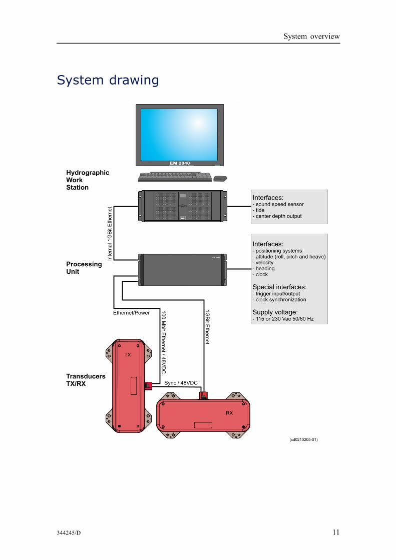
System characteristicsMain unitsThe EM 2040 consists of four main units:• Transmit transducer• Receive transducer(s)• Processing Unit (PU)• Operator Station (HWS)A complete system for seabed mapping will in addition include a transducer mountingplate, a motion sensor, a heading sensor, a sound velocity sensor and a positioning system.
TransducersThe EM 2040 transducers consist of separate linear arrays for transmit and receive in aMills cross configuration. The transmit array is electronically steerable alongtrack whilethe receive array is steerable athwartship. Both arrays contain all analog electronics anddigital control units with Ethernet interfaces to the processing unit.The transducers are made from composite ceramics, designed and tested to operate to adepth of 6000 m. The transmitter array consists of three separate line arrays, one lookingstraight downwards and the two others pointing 55° to each side.The transducers have Ethernet data interfaces. The receiver uses Gbit Ethernet whilst thetransmitter uses 100 Mbit Ethernet. The transmitter also has 48 VDC supply which isrouted to the receiver. The interconnecting cable included also carries a synchronizationsignal.The material in the transducer housing is Titanium.The EM 2040 is delivered with a mounting plate with factory aligned guidances. It isrecommended that the mounting plate is built into a steel casing and protected by abaffle for multipath reduction. Optionally, the transducers may be delivered mounted ona frame together with the motion sensor and a sound speed sensor, factory aligned forease of mounting.The EM 2040 is fully prepared for upgrading to cater for more demanding applications.Adding a second receive transducer increases the angular coverage to up to 200° (±100°).
Processing unitThe EM 2040 processing unit is basically a Compact PCI standard computer using acommercially available CPU board with an Intel dual core CPU, plus signal processingboards. Receive data from the Gbit link is match filtered by an FPGA board beforetransferred to the signal processing boards. The CPU board has serial interfaces forinput of external time-critical sensors and Gigabit Ethernet for communication with theoperator station. SATA interfaces are available for integrated data logging to a localhard disk (option intended for AUV use).Currently the EM 2040 system requires one PU per RX transducer and one additionalPU per RX transducer for dual swath capability.
344245/D 7
Kongsberg EM 2040
The Processing Unit also supplies 48 Vdc power to the transducers.
Operator station
The Operator Station of the EM 2040 is the standard HWS (Hydrographic Work Station)high performance PC work station. The operator software is SIS (Seafloor InformationSystem).
As a minimum, the unlicensed version of SIS allows for setting the EM 2040 installationand runtime parameters, logging and displaying data, as well as running the built inself tests.
The licensed version of the SIS software also includes functionality for survey planning,real-time 2D and 3D geographical display of the survey data, seabed image and watercolumn displays. There are also real-time data cleaning algorithms available.
Alternatively, third-party software solutions can be used for operator interface andreal-time processing. Contact Kongsberg Maritime for information.
The HWS is normally supplied with a 19” industrialized LCD monitor with a resolutionof 1280x1024 pixels. Support for up to four monitors is available. A spill proof USkeyboard and a standard optical mouse is normally supplied, but optionally a small IP 65rated keyboard with integrated track stick can be delivered.
Interfaces
For completeness, data input from an attitude sensor, a heading sensor and a positioningsystem is required, as is the sound speed profile of the water column between thetransducers and the bottom. Sound speed at the transducer, clock and 1PPS are optionalinputs.
The EM 2040 will be equipped to handle the IEEE 1588 time synchronization system,and to support the better time accuracy this provides. Multiple sensors supplying thesame type of data may be logged. Data input is usually on serial line, but Ethernet inputis also supported. The processing unit has full trigging capability and 1 PPS signalinterface.
The formats currently supported by Kongsberg Maritime's range of multibeam echosounders will be retained, likewise the time-tagging principles used. All data aretime-tagged using the same clock reference as the multibeam.
Transmit signal characteristics
The signals employed are either CW pulses with effective pulse length from 25 to600 μs or FM chirps with a pulse length up to 12 ms, the latter used to increase rangecapability. Increased coverage with more than 35% has been verified when switchingfrom the longest CW pulse to FM pulse for the 300 kHz mode. The transmitted signalsare shaded in time (tapered) to reduce out of band leakage, in practice the CW signallength is 50% larger than the effective pulse length. Power reduction of 10 and 20 dB ispossible, selected by the operator.
8 344245/D
System overview
Transmission beam
Three transmit sectors are normally used per swath. Shading is employed to reduce sidelobes. Alongtrack steering of the sectors take into account both yaw and pitch to positionthe transmit footprints as closely as possible perpendicular to the survey line direction.The alongtrack beam is steerable within ±10º. The sectors will normally use differentfrequencies and they will transmit simultaneously.
To compensate for nearfield effects the transmission of the sectors are focused at therange determined from the previous ping. The focusing range will usually differ betweenthe three transmit sectors.
Ping rate
The ping rate is normally only limited by the two-way travel time, with very littleadditional delay required. The maximum range required per ping is determinedautomatically, taking into account the need to sample the full width of the outermostbeam as well as that the depth may increase on the next ping. Maximum ping rate is 50Hz. This can be reduced by the operator or controlled by external sync.
Signal processing
To increase the transmit source level and to reduce the effect of multipaths, the EM 2040uses several transmit sectors per swath. To avoid crosstalk between the sectors, highprecision bandpass filters are implemented to match the transmitted signals. Also thetransmit waveforms are formed to avoid out of band components. The receiver has a veryhigh instantaneous dynamic range, removing the need for analogue gain control (TVG).
Beam characteristics
The beam forming uses split beam technology.
The beamforming uses real-time roll (i.e. the beams are fully roll stabilized) anddynamic focusing in the near-field region. Sound speed at the transducer depth is usedas well; it may preferable be read from a real-time sensor, interpolated from the soundspeed profile or from an operator entered value.
The beam spacing may be set to equidistant or equiangle. 256 actual beams are formedper swath for a 1 degree receiver, spaced over an angular sector which is configurable orderived from the actual coverage achieved.
When using high density processing more than one detection is derived from each beam.The spacing of the soundings is chosen so that equidistant sampling of the bottom isachieved. The high density mode is used to increase the number of soundings from themultibeam echo sounders with up to 400 soundings per swath.
While operating in the single sector mode the system may reduce the number of beamsand number of soundings. The actual numbers depend on the pulse length.
344245/D 9
Kongsberg EM 2040
Bottom detection
The phase difference between the halfbeams, which is a measure of the angle of arrivalof the returned echo, is calculated. A curve fit is made to the resulting time series ofphase, from which the zero phase crossing is found determining the range to the bottomin the centre of the beam.
When high density mode is enabled, the phase curve for a beam is used to derive morethan one detection and not only at the centre of the beam. The detection window isshortened accordingly, and the spacing of the soundings is chosen so that equidistantsampling of the bottom is achieved. This mode is used to increase the number ofsoundings available from the multibeam echo sounders with up to 400 soundings perswath.
The footprint will typically be two times the across sampling distance.
Amplitude-based bottom detection is the alternative to phase detection when the numberof samples is too small or the phase curve too noisy, typically at small incidence anglesor depths.
Depth corrections
The bottom detection process determines the two-way travel time and angle to thebottom in a transducer fixed coordinate system. The sound speed at the transducer depth,the sound speed profile and the vessel attitude both at transmit and receive time are thenemployed to calculate the Cartesian coordinates of each sounding relative to the watersurface and vessel heading. Attitude offsets, time delay and sensor locations includingvessel travel are employed in this procedure. The refraction calculations are done usingSnell’s law assuming constant gradients within the layers defined by the sound speedprofile, starting at the actual depth of the transmit transducer at the transmit time.
Seabed imagery
The principles used in the current Kongsberg Maritime multibeam echo sounders areretained in the EM 2040. This implies that each sounding will include a measure ofthe bottom’s backscatter strength. Imagery data samples will be derived for everyrange sample giving a time continuous high resolution record across for each ping.The imagery record is extended over gaps due to missing beams and also beyond thatof the outermost valid detection.
The backscattering calculation principles used in the current Kongsberg Maritimemultibeam echo sounders are also retained. The fact that no TVG is applied in thereceiver is compensated through the use of the same model as in the other Kongsbergmultibeam echo sounders.
Water column data
The beam amplitudes from the water column can be displayed at the operator station.The data can optionally be logged to a separate file or logged together with the restof the echo sounder datagrams.
10 344245/D
System overview
System drawing
344245/D 11
Kongsberg EM 2040
Performance
EM 2040 swath width calculations
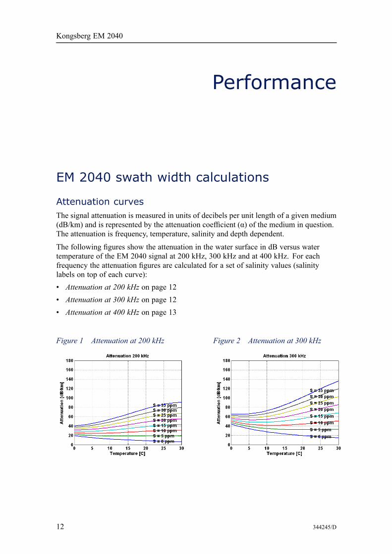
Attenuation curvesThe signal attenuation is measured in units of decibels per unit length of a given medium(dB/km) and is represented by the attenuation coefficient (α) of the medium in question.The attenuation is frequency, temperature, salinity and depth dependent.
The following figures show the attenuation in the water surface in dB versus watertemperature of the EM 2040 signal at 200 kHz, 300 kHz and at 400 kHz. For eachfrequency the attenuation figures are calculated for a set of salinity values (salinitylabels on top of each curve):• Attenuation at 200 kHz on page 12• Attenuation at 300 kHz on page 12• Attenuation at 400 kHz on page 13
Figure 1 Attenuation at 200 kHz Figure 2 Attenuation at 300 kHz
12 344245/D
Performance
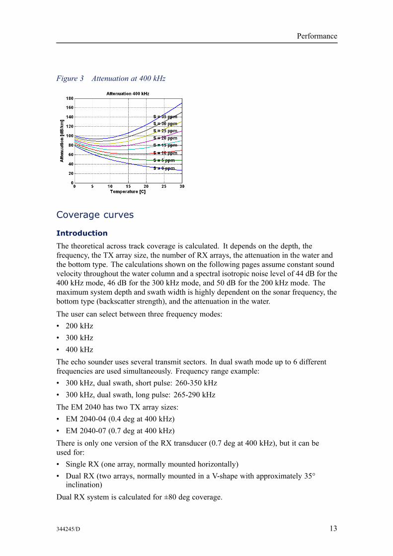
Figure 3 Attenuation at 400 kHz
Coverage curves
Introduction
The theoretical across track coverage is calculated. It depends on the depth, thefrequency, the TX array size, the number of RX arrays, the attenuation in the water andthe bottom type. The calculations shown on the following pages assume constant soundvelocity throughout the water column and a spectral isotropic noise level of 44 dB for the400 kHz mode, 46 dB for the 300 kHz mode, and 50 dB for the 200 kHz mode. Themaximum system depth and swath width is highly dependent on the sonar frequency, thebottom type (backscatter strength), and the attenuation in the water.The user can select between three frequency modes:• 200 kHz• 300 kHz• 400 kHzThe echo sounder uses several transmit sectors. In dual swath mode up to 6 differentfrequencies are used simultaneously. Frequency range example:• 300 kHz, dual swath, short pulse: 260-350 kHz• 300 kHz, dual swath, long pulse: 265-290 kHzThe EM 2040 has two TX array sizes:• EM 2040-04 (0.4 deg at 400 kHz)• EM 2040-07 (0.7 deg at 400 kHz)There is only one version of the RX transducer (0.7 deg at 400 kHz), but it can beused for:• Single RX (one array, normally mounted horizontally)• Dual RX (two arrays, normally mounted in a V-shape with approximately 35°
inclination)Dual RX system is calculated for ±80 deg coverage.
344245/D 13
Kongsberg EM 2040
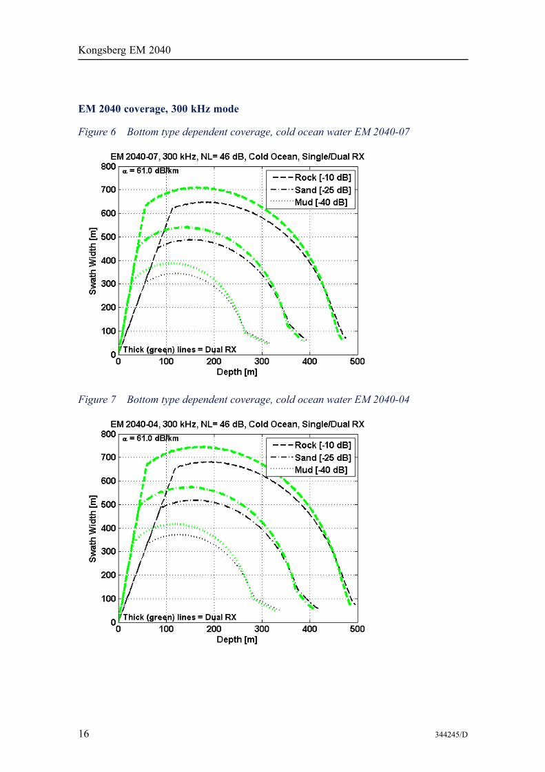
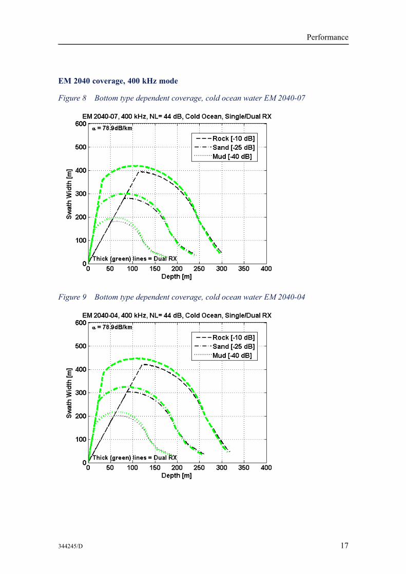
The first graphs shows the bottom type dependent coverage for cold ocean water, withthree different bottom types, for the two TX array sizes, EM 2040–04 and EM 2040–07,and for single and dual RX
The next graph shows the dependency of the attenuation in the water column.
The last graphs shows example of measured coverage.
Coverage as function of bottom type
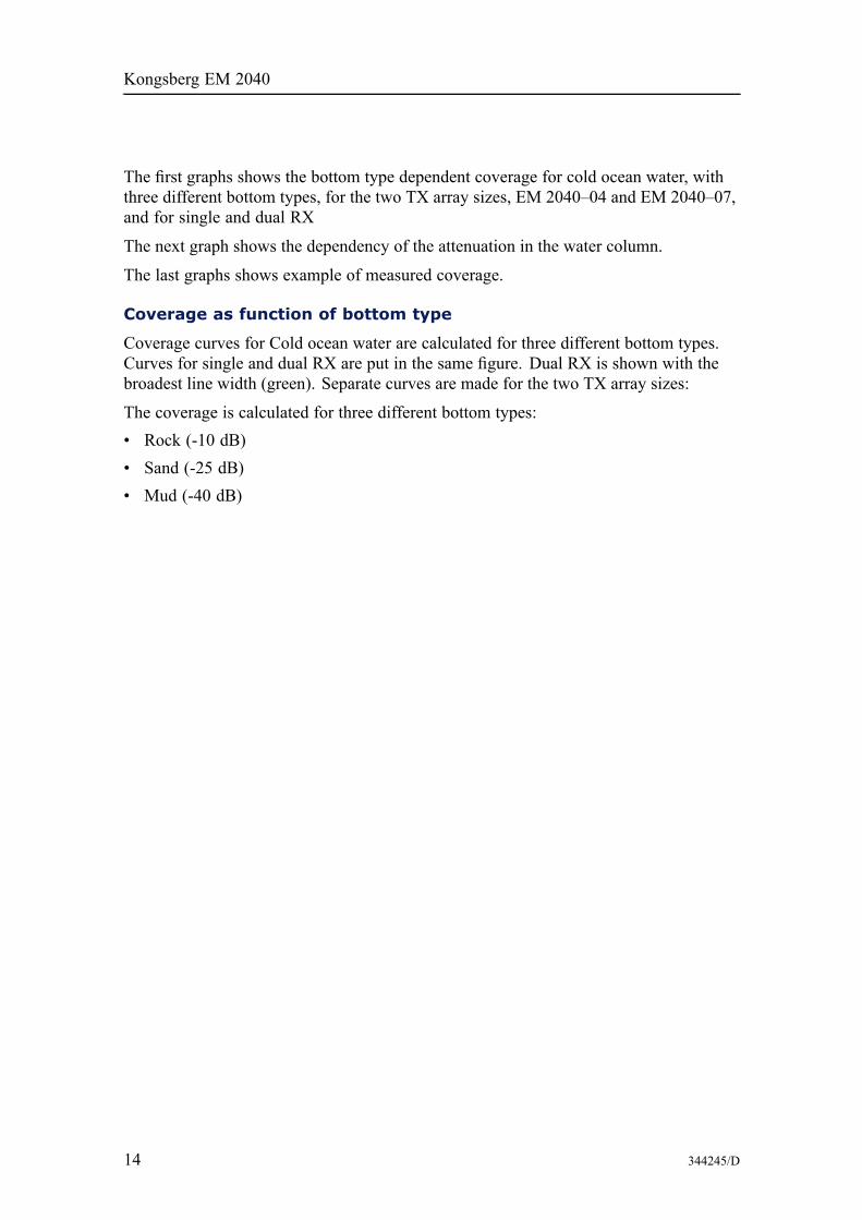
Coverage curves for Cold ocean water are calculated for three different bottom types.Curves for single and dual RX are put in the same figure. Dual RX is shown with thebroadest line width (green). Separate curves are made for the two TX array sizes:
The coverage is calculated for three different bottom types:• Rock (-10 dB)• Sand (-25 dB)• Mud (-40 dB)
14 344245/D
Performance
EM 2040 coverage, 200 kHz mode
Figure 4 Bottom type dependent coverage, cold ocean water EM 2040-07
Figure 5 Bottom type dependent coverage, cold ocean water EM 2040-04
344245/D 15
Kongsberg EM 2040
EM 2040 coverage, 300 kHz mode
Figure 6 Bottom type dependent coverage, cold ocean water EM 2040-07
Figure 7 Bottom type dependent coverage, cold ocean water EM 2040-04
16 344245/D
Performance
EM 2040 coverage, 400 kHz mode
Figure 8 Bottom type dependent coverage, cold ocean water EM 2040-07
Figure 9 Bottom type dependent coverage, cold ocean water EM 2040-04
344245/D 17
Kongsberg EM 2040
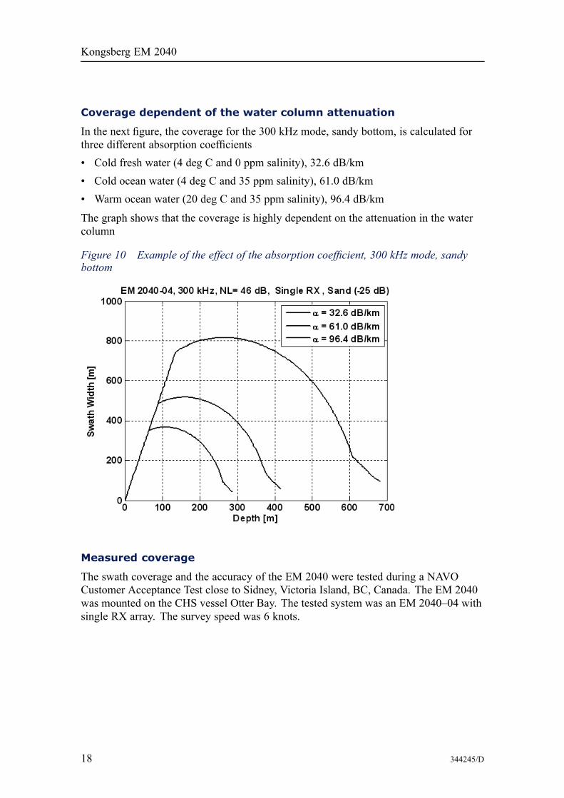
Coverage dependent of the water column attenuation
In the next figure, the coverage for the 300 kHz mode, sandy bottom, is calculated forthree different absorption coefficients• Cold fresh water (4 deg C and 0 ppm salinity), 32.6 dB/km• Cold ocean water (4 deg C and 35 ppm salinity), 61.0 dB/km• Warm ocean water (20 deg C and 35 ppm salinity), 96.4 dB/km
The graph shows that the coverage is highly dependent on the attenuation in the watercolumn
Figure 10 Example of the effect of the absorption coefficient, 300 kHz mode, sandybottom
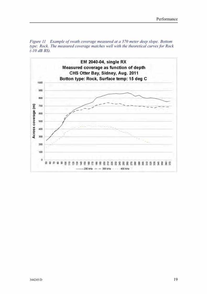
Measured coverage
The swath coverage and the accuracy of the EM 2040 were tested during a NAVOCustomer Acceptance Test close to Sidney, Victoria Island, BC, Canada. The EM 2040was mounted on the CHS vessel Otter Bay. The tested system was an EM 2040–04 withsingle RX array. The survey speed was 6 knots.
18 344245/D
Performance
Figure 11 Example of swath coverage measured at a 370 meter deep slope. Bottomtype: Rock. The measured coverage matches well with the theoretical curves for Rock(-10 dB BS).
344245/D 19
Kongsberg EM 2040
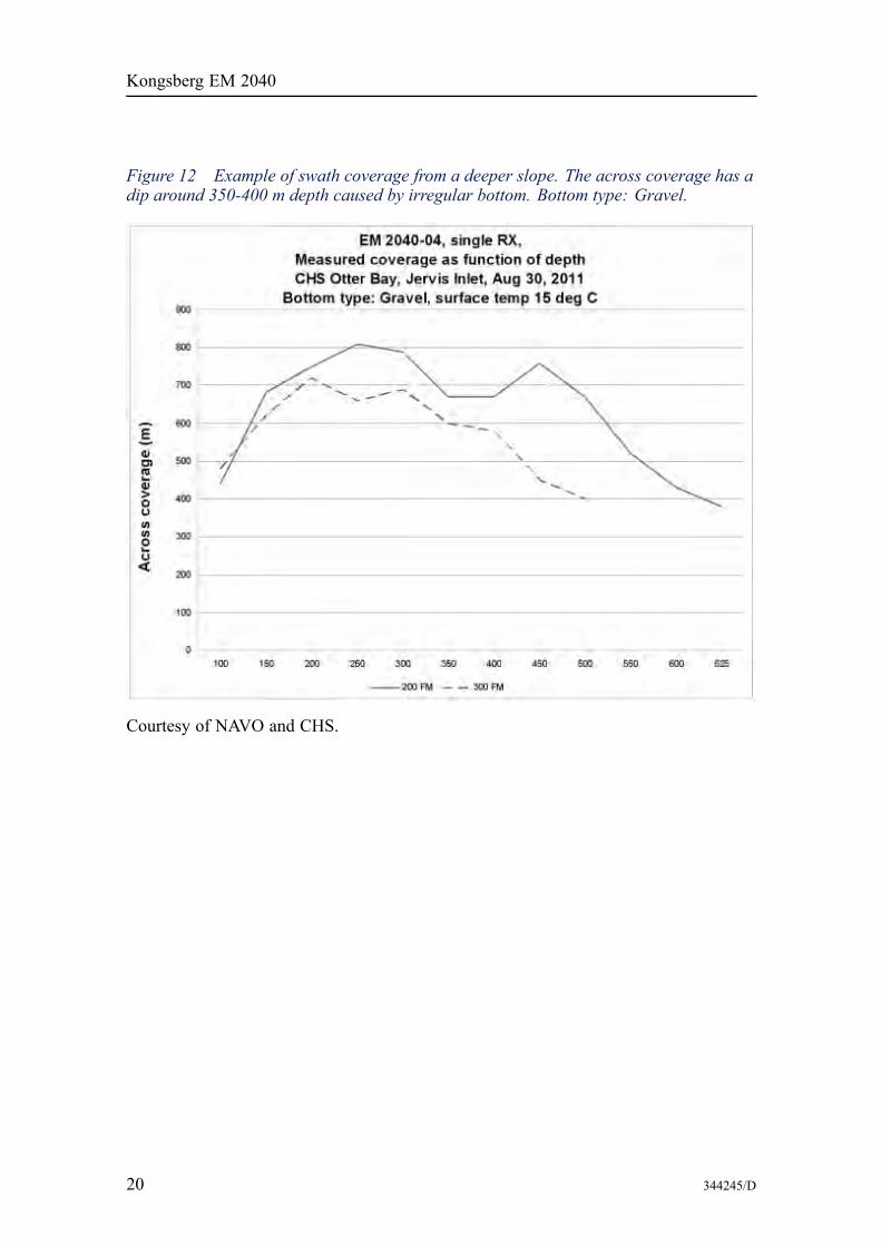
Figure 12 Example of swath coverage from a deeper slope. The across coverage has adip around 350-400 m depth caused by irregular bottom. Bottom type: Gravel.
Courtesy of NAVO and CHS.
20 344245/D
Performance
Depth accuracyThe depth sounding accuracy of EM 2040 is very good thanks to narrow transmit andreceive beams, large transmit bandwidth and matching receivers. This is combined withprecise digital beamforming, range dependent beam focusing and a high sampling rate.Important is also the advanced bottom detection methods proven through many yearsof experience with the Kongsberg range of multibeam echo sounders. The predictedsystem depth errors are in the order of 0.1% of depth, limited in very shallow waters toabout the range sampling distance.Near normal incidence a centre of gravity amplitude detection is used, but for themajority of the beams the system uses phase detection.From all bottom returns, inside a processing window inside a beam, the exact rangeand angle to the bottom in the centre of the processing window is derived. The size ofthe detection windows is tuned according to the across sampling density, to minimizeoverlap between soundings.In addition to the echosounder itself, the total system accuracy will also depend uponthe quality of the installation, the external sensors (position, velocity, motion and soundspeed) and the oceanographic conditions. Varying sound velocity layers in the watercolumn in the survey area may degrade the result.The expected total system RMS accuracy, assuming a correct calibrated installation,good quality external sensors and acceptable oceanographic and weather conditions, isexpected to be better than the largest number of 5 cm (normally limited by heave sensor)and:Short and medium CW pulses:• 0.10% of the depth (from vertical up to 45 degrees)• 0.15% of depth (up to 60 degrees)• 0.30% of the depth (up to 70 degrees)Long CW and FM pulses:• 0.15% of the depth (from vertical up to 45 degrees)• 0.25% of depth (up to 60 degrees)• 0.40% of the depth (up to 70 degrees)These numbers are valid for signal to noise ratio better than 10 dB.Please be aware that with optimal installation and good oceanographic conditions evenbetter accuracy can be achieved, as shown in the examples in the following figures:• 300 kHz mode, short pulse, 140 deg swath, 20 m depth (0.15% = 3 cm at 20 mdepth) on page 22
• 300 kHz mode, single sector, short pulse, 120 deg swath, 50 m depth on page 22• 400 kHz mode, short pulse, 120 deg swath, 50 m depth on page 22• 400 kHz mode, single sector, short pulse, 80 deg swath, 50 m depth on page 23• 200 kHz mode, short pulse, 140 deg swath, 50 m depth on page 23
344245/D 21
Kongsberg EM 2040
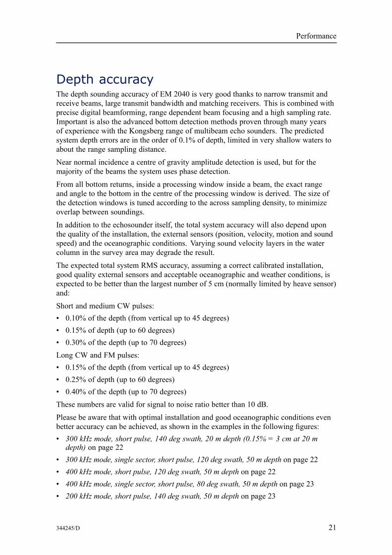
Measured standard deviationSurvey examples from NAVO Sea Acceptance Test, showing measured standarddeviation in percentage of depth:
Figure 13 300 kHz mode, short pulse, 140 deg swath, 20 m depth (0.15% = 3 cmat 20 m depth)
Figure 14 300 kHz mode, single sector, short pulse, 120 deg swath, 50 m depth
Figure 15 400 kHz mode, short pulse, 120 deg swath, 50 m depth
22 344245/D
Performance
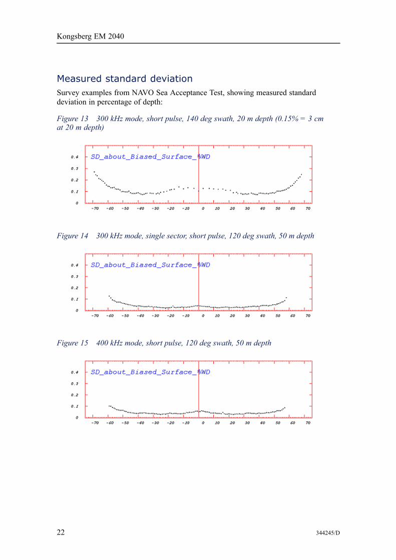
Figure 16 400 kHz mode, single sector, short pulse, 80 deg swath, 50 m depth
Figure 17 200 kHz mode, short pulse, 140 deg swath, 50 m depth
Courtesy of NAVO, CHS and UNB
Horizontal resolutionThe depth dependent horizontal resolution depends on
Alongship• TX beam width (defines footprint along)• Vessel speed (sample density along)• Swath rate (sample density along)
Across ship• Number of RX soundings (defines the sample density across)• Detection window size (defines the footprint across)
The swath rate depends on depth and swath width. In dual swath mode two swaths aremade per ping, then the swath rate is two times the ping rate.
The across ship footprint is defined as two times the across sampling distance. Thismatches a normal bottom detect range window.
344245/D 23
Kongsberg EM 2040
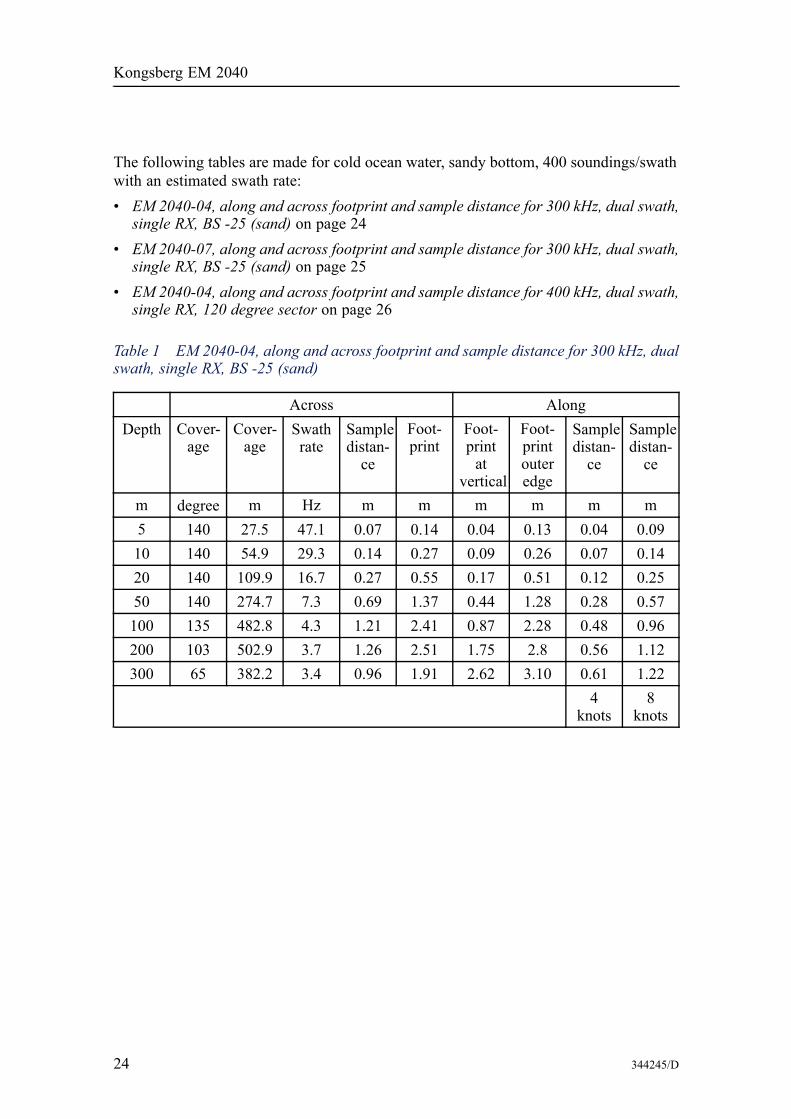
The following tables are made for cold ocean water, sandy bottom, 400 soundings/swathwith an estimated swath rate:• EM 2040-04, along and across footprint and sample distance for 300 kHz, dual swath,single RX, BS -25 (sand) on page 24
• EM 2040-07, along and across footprint and sample distance for 300 kHz, dual swath,single RX, BS -25 (sand) on page 25
• EM 2040-04, along and across footprint and sample distance for 400 kHz, dual swath,single RX, 120 degree sector on page 26
Table 1 EM 2040-04, along and across footprint and sample distance for 300 kHz, dualswath, single RX, BS -25 (sand)
Across AlongDepth Cover-
ageCover-age
Swathrate
Sampledistan-ce
Foot-print
Foot-printat
vertical
Foot-printouteredge
Sampledistan-ce
Sampledistan-ce
m degree m Hz m m m m m m5 140 27.5 47.1 0.07 0.14 0.04 0.13 0.04 0.0910 140 54.9 29.3 0.14 0.27 0.09 0.26 0.07 0.1420 140 109.9 16.7 0.27 0.55 0.17 0.51 0.12 0.2550 140 274.7 7.3 0.69 1.37 0.44 1.28 0.28 0.57100 135 482.8 4.3 1.21 2.41 0.87 2.28 0.48 0.96200 103 502.9 3.7 1.26 2.51 1.75 2.8 0.56 1.12300 65 382.2 3.4 0.96 1.91 2.62 3.10 0.61 1.22
4knots
8knots
24 344245/D
Performance
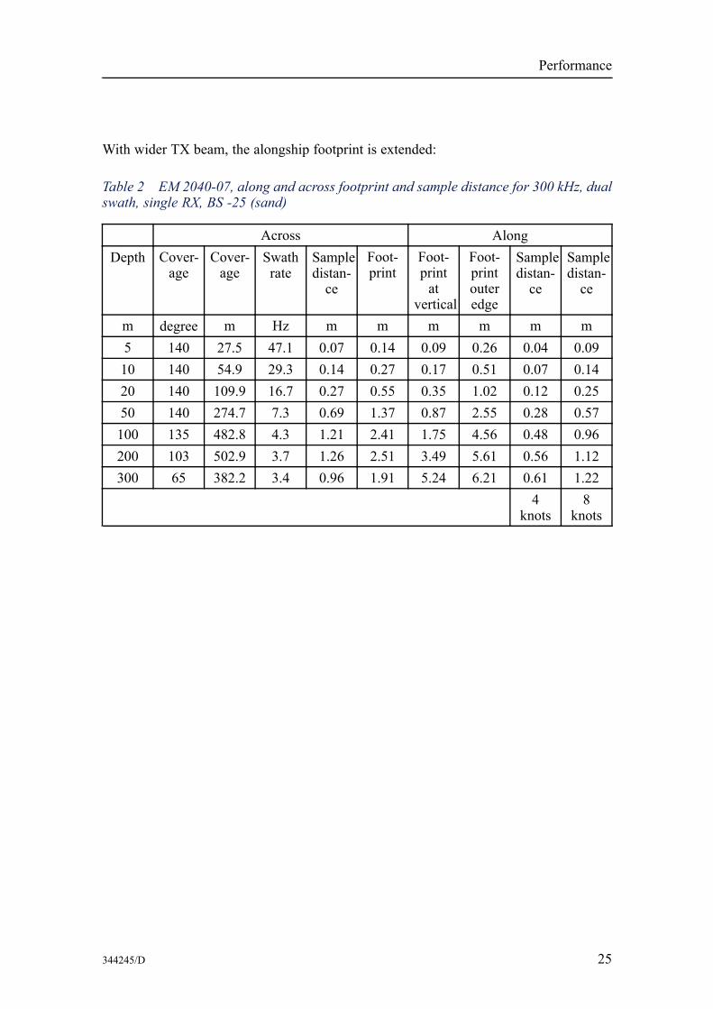
With wider TX beam, the alongship footprint is extended:
Table 2 EM 2040-07, along and across footprint and sample distance for 300 kHz, dualswath, single RX, BS -25 (sand)
Across AlongDepth Cover-
ageCover-age
Swathrate
Sampledistan-ce
Foot-print
Foot-printat
vertical
Foot-printouteredge
Sampledistan-ce
Sampledistan-ce
m degree m Hz m m m m m m5 140 27.5 47.1 0.07 0.14 0.09 0.26 0.04 0.0910 140 54.9 29.3 0.14 0.27 0.17 0.51 0.07 0.1420 140 109.9 16.7 0.27 0.55 0.35 1.02 0.12 0.2550 140 274.7 7.3 0.69 1.37 0.87 2.55 0.28 0.57100 135 482.8 4.3 1.21 2.41 1.75 4.56 0.48 0.96200 103 502.9 3.7 1.26 2.51 3.49 5.61 0.56 1.12300 65 382.2 3.4 0.96 1.91 5.24 6.21 0.61 1.22
4knots
8knots
344245/D 25

Kongsberg EM 2040
At 400 kHz with narrow beams and 120 degree sector, sample distance and footprints arereduced:
Table 3 EM 2040-04, along and across footprint and sample distance for 400 kHz,dual swath, single RX, 120 degree sector
Across AlongDepth Cover-
ageCover-age
Swathrate
Sampledistan-ce
Foot-print
Foot-printat
vertical
Foot-printouteredge
Sampledistan-ce
Sampledistan-ce
m degree m Hz m m m m m m5 120 17.3 60.3 0.04 0.09 0.03 0.07 0.03 0.0710 120 34.6 40.3 0.09 0.17 0.07 0.14 0.05 0.1015 120 52.0 30.2 0.13 0.26 0.10 0.21 0.07 0.1420 120 69.3 24.2 0.17 0.35 0.14 0.28 0.09 0.1740 120 138.6 13.5 0.35 0.69 0.28 0.56 0.15 0.3160 120 207.8 9.3 0.52 1.04 0.42 0.84 0.22 0.4480 120 277.1 7.1 0.69 1.39 0.56 1.12 0.29 0.58
4knots
8knots
26 344245/D
Performance
EM 2040 object detection capabilityIn general, the object detection capabilities of multibeam echo sounders are given bytwo requirements:A That the object is sufficiently large to be detected within a soundingB That there are a sufficient number of soundings hitting the object to avoid filtering
the object as noise during the processingA general rule-of-thumb for the first requirement for an object lying on the bottom is thatthe object size must not be smaller than approximately 50% of the beam footprint (asdefined either by angular beamwidth or detection window length). In accordance withthe LINZ hydrographic specification the latter requirement is met by demanding that thesounding boresight spacing is not less than half the object size both across and along.The higher resolution models will have somewhat better sounding accuracy than themodels with wider beams, especially in rugged terrain, and will have better capabilityfor object detection.The error sources of multibeam bathymetry lies within the echo sounder itself, themotion sensor, within position determination and in the sound speed. With the assumedaccuracy of the motion sensor and within a coverage sector limited to 5 times waterdepth, it can be expected that the maximum error depends on the pulse length employed(disregarding sound speed errors).With the sampling rate matching the pulse length specified, the accuracy can then beexpect to be better than cτ/4, i.e. less than 10 mm for a 25 μs pulse, provided that asufficient signal to noise ratio is obtained (not less than 10 dB).The EM 2040 is well suited for surveys meeting the IHO-S44 special order. Dependingon which version of EM 2040 is selected, different capabilities for object detectionare obtained.IHO special order requires that objects down to 1 m3 shall be detected, whilst the IHOorder 1 requires that objects down to 2 m3shall be detected to 40 m water depth.LINZ raises an additional condition or clarification. The object shall have at least 9 hits,3 along and 3 across. The reason for this is that automatic algorithms for cleaning ofbathymetric data will remove isolated soundings, but accept a cluster of soundings.Equidistant pattern of soundings is ideal for object detection. Also the refined and smallacoustic footprint which is obtained with the high density signal processing favourobject detection.A necessary feature for reliable object detection in rough sea conditions is activestabilization of the beams for ship pitching and yawing. For the EM 2040 full vesselmovement compensation is built in, including yaw compensation, and beam focusing isstandard both on transmit and receive. For depths exceeding 20 m using a small boat incroppy seas, beam stabilization is an important requirement.
Object detection simulationFor the EM 2040 simulations whereby an object is placed in the outmost of the beamshave been carried out. Three swath widths have been simulated.
344245/D 27
Kongsberg EM 2040
Four cases have been assessed:• 1 m3 cube, single swath• 2 m3 cube, single swath• 1 m3 cube, dual swath• 2 m3 cube, dual swath
These cases are calculated for an EM 2040–04 and an EM 2040–07.
In the following figures a square with colour code for swath width is drawn when thecriteria for detection are fulfilled. The figures show that for an EM 2040–07 transducerthe 1 m3 cube object is not detected neither at depth 30 m at survey speed 16 knots, norat depth 40 m with survey speed 12 and 16 knots, even with 90 degrees swath. Whenincluding dual swath the object will have enough hits width 90 degrees swath width to bedetected at both 30 and 40 meters up to 16 knots survey speed.
An EM 2040–04 system operating in single swath will also have problems detecting the1 m3 cube at high survey speed. Dual swath ensures detection of the 1 m cube.
28 344245/D
Performance
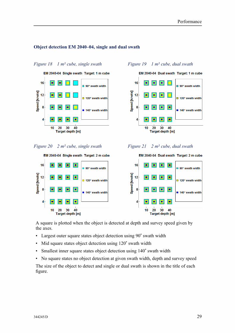
Object detection EM 2040–04, single and dual swath
Figure 18 1 m3 cube, single swath Figure 19 1 m3 cube, dual swath
Figure 20 2 m3 cube, single swath Figure 21 2 m3 cube, dual swath
A square is plotted when the object is detected at depth and survey speed given bythe axes.• Largest outer square states object detection using 90° swath width• Mid square states object detection using 120° swath width• Smallest inner square states object detection using 140° swath width• No square states no object detection at given swath width, depth and survey speedThe size of the object to detect and single or dual swath is shown in the title of eachfigure.
344245/D 29
Kongsberg EM 2040
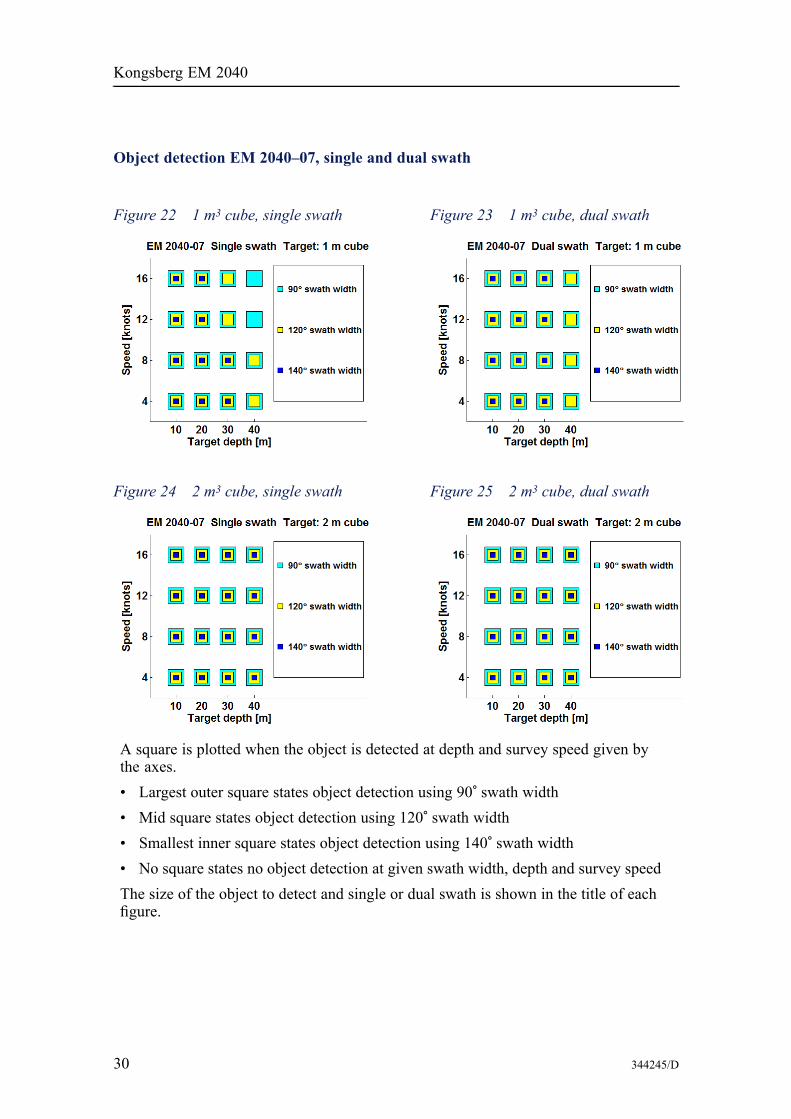
Object detection EM 2040–07, single and dual swath
Figure 22 1 m3 cube, single swath Figure 23 1 m3 cube, dual swath
Figure 24 2 m3 cube, single swath Figure 25 2 m3 cube, dual swath
A square is plotted when the object is detected at depth and survey speed given bythe axes.• Largest outer square states object detection using 90° swath width• Mid square states object detection using 120° swath width• Smallest inner square states object detection using 140° swath width• No square states no object detection at given swath width, depth and survey speedThe size of the object to detect and single or dual swath is shown in the title of eachfigure.
30 344245/D

Installation principals
Installation principals
The compactness of the EM 2040 multibeam echo sounder is a guarantee for a fastand easy installation. For a surface vessel, the Operator Station and the ProcessingUnits are placed inside the vessel whilst the transducer arrays are mounted so that theyare always submerged in water.
Operator stationThe Operator Station is a ruggedized PC workstation, prepared for mounting in astandard 19” rack (requires 4 rack height units). It is supplied with a 19” industrial LCDmonitor, a keyboard and an optical mouse. A bracket for the monitor is included fortable top, bulkhead and roof mounting.
Processing unitsOne Processing Unit is required per RX transducer and one additional PU is required perRX transducer for dual swath capability.
The Processing Units (PUs) may be mounted in a standard 19” rack, requiring 4U (4rack height units) per PU.
On large vessels the PUs may have to be mounted closer to the transducer arrays thanthe Operator Station due to restricted length of the cable connecting the two units (15 mstandard length, optional 30 and 50 m).
Solutions for mounting the Processing Units in an underwater vehicle is available.
Transducer array installationCorrect location, orientation and alignment of the system’s transducer is vital for theperformance of the EM 2040. A transducer mounting plate is provided with the systemto ensure accurate relative orientation of the transducers. Further, the transducer arraysmust be mounted such that the water in front of the arrays is not aerated.
344245/D 31
Kongsberg EM 2040
The transducers can be rotated 180° to ease cabling. Installation parameters must beset accordingly.
Kongsberg Maritime's recommendations for optimal installation of the EM 2040 systemis described in this section.
To ease installation, as well as ensuring that the relative alignment between thetransducers are determined within the required accuracy, a Kongsberg Maritimefabricated mounting plate is delivered with the EM 2040 transducer arrays. Themounting plate is fitted with a guidance system that ensures that the transducer arraysare aligned within the required accuracy.
The requirement for knowing the relative heading between the EM 2040 RX and TXtransducers are extremely strict, and can only be met using high precision land surveymethods and equipment. Also the mechanical mounting of the arrays must be carried outwith this requirement in mind. The slightest slack will degrade the system performance.
We strongly advise using the mounting plate that is provided.
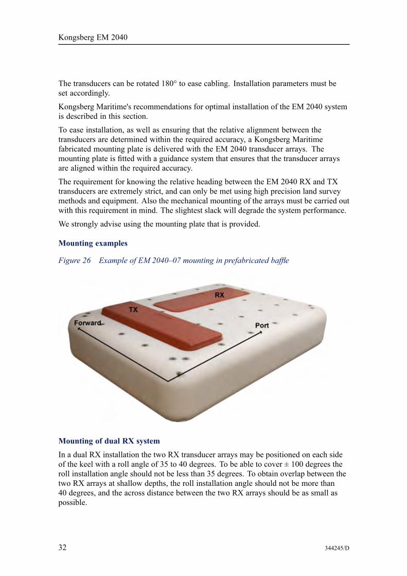
Mounting examples
Figure 26 Example of EM 2040–07 mounting in prefabricated baffle
Mounting of dual RX system
In a dual RX installation the two RX transducer arrays may be positioned on each sideof the keel with a roll angle of 35 to 40 degrees. To be able to cover ± 100 degrees theroll installation angle should not be less than 35 degrees. To obtain overlap between thetwo RX arrays at shallow depths, the roll installation angle should not be more than40 degrees, and the across distance between the two RX arrays should be as small aspossible.
32 344245/D
Installation principals
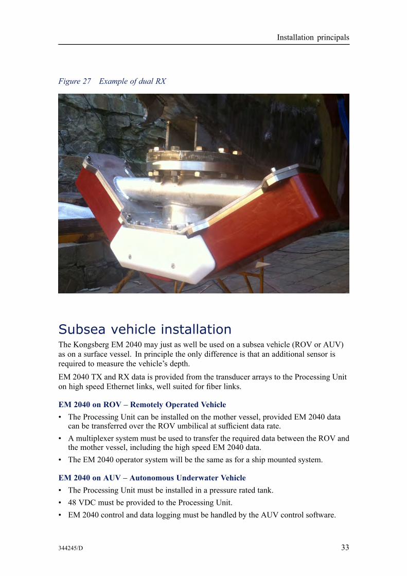
Figure 27 Example of dual RX
Subsea vehicle installationThe Kongsberg EM 2040 may just as well be used on a subsea vehicle (ROV or AUV)as on a surface vessel. In principle the only difference is that an additional sensor isrequired to measure the vehicle’s depth.EM 2040 TX and RX data is provided from the transducer arrays to the Processing Uniton high speed Ethernet links, well suited for fiber links.
EM 2040 on ROV – Remotely Operated Vehicle• The Processing Unit can be installed on the mother vessel, provided EM 2040 data
can be transferred over the ROV umbilical at sufficient data rate.• A multiplexer system must be used to transfer the required data between the ROV and
the mother vessel, including the high speed EM 2040 data.• The EM 2040 operator system will be the same as for a ship mounted system.
EM 2040 on AUV – Autonomous Underwater Vehicle• The Processing Unit must be installed in a pressure rated tank.• 48 VDC must be provided to the Processing Unit.• EM 2040 control and data logging must be handled by the AUV control software.
344245/D 33
Kongsberg EM 2040
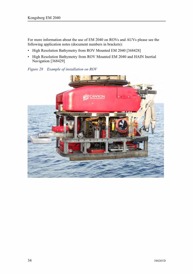
For more information about the use of EM 2040 on ROVs and AUVs please see thefollowing application notes (document numbers in brackets):• High Resolution Bathymetry from ROV Mounted EM 2040 [368428]• High Resolution Bathymetry from ROV Mounted EM 2040 and HAIN Inertial
Navigation [368429]
Figure 28 Example of installation on ROV
34 344245/D
Operational principals
Operational principals
System featuresThe EM 2040 multibeam echo sounder is controlled from the HWS Operator Stationusing the Seafloor Information System – SIS software. As standard, the systemsoftware includes the necessary features for system installation, testing and running themultibeam, ping related displays (including water column display) and the capabilityof logging the acquired bathymetry data.
The EM 2040 system does not require operator intervention during normal operation,but tracks the bottom automatically while adjusting mode, gain and range dependentparameters as required. Before operation is started, the necessary external sensors, suchas positioning and vessel motion sensors, are connected and calibration proceduresfollowed in order to define the system and sensor installation parameters. The systemincludes an automatic calibration facility
Parameters critical to data quality are password protected and can be recalled. Seabedimagery data is available from the system as standard. The imagery data, representingthe acoustic backscatter strength of the bottom, is available in two forms. One nominallycorrected for the effect of incidence angle (seabed image data), the other given perbeam as an absolute measure (beam intensity). The imagery data may be useful forobject detection, but the most important application is probably geophysical for seabedcharacterization.
Seafloor Information System — SISSeafloor Information System (SIS) is a real time software designed to be the user interfaceand real time data processing system for all hydrographic instruments produced byKongsberg Maritime AS. SIS is included on all deliveries of multibeam echo soundersfrom Kongsberg Maritime.
The main task for SIS is to be an intuitive and user friendly interface for the surveyor,providing the functionality needed for operation of the multibeam echo sounder andrunning a survey efficiently. SIS includes the necessary features for system installation,testing and operating the multibeam echo sounder, ping related displays (including watercolumn display) and the capability of logging the acquired bathymetry data.
344245/D 35
Kongsberg EM 2040
SIS runs under the Windows XP or Win7 operating system with the HWS (HydrographicWork Station) operator PC hardware. Up to four screens can be used on one HWS, andSIS can also show geographical displays on several remote PCs in the network.The Kongsberg Maritime echo sounders are complete systems. All necessary sensorinterfaces, data displays for quality control and sensor calibration, seabed visualization,and data logging are standard parts of the systems, as is integrated seabed acousticalimaging capability (sidescan).The available features of SIS are:• Screen layout with up to seven simultaneous display windows defined by the user• Real time data cleaning of bathymetric data• Enhanced functions for visual and automated data quality control• Geographical displays for sound speed at sonar head and sound speed profile• Built in self tests of the multibeam echo sounder and continuous monitoring the
quality of input data. Error situations are logged, and user notifications are givenadvising what action to take.
• High resolution seabed image mosaic can be viewed in the Geographical view• Unique features for plotting of scaled maps in size up to A0• Imaging of acoustic reflectors in the water column (fish, biomass, etc.)• Real time computation of the mean sea level using a geoid model• Real time compensation for tide• Fully operational when echo sounder is mounted on ROV/AUV• Post processing of GNSS raw position data using Precise Point PositioningBasic version – Instrument controlWith the basic/instrument control version of SIS you can select which instrument tooperate, turn it on/off, store data on/off, change setup and operating parameters andexport data. There are graphical windows for quality checking of sensor input and thedata produced. Sound speed at sonar head and sound speed profile input are interfacedand handled correctly in real time.Multibeam echo sounders have built-in tests which can be activated to verify that thehardware is working correctly. In addition SIS constantly monitors input data to ensurethe data quality. Error situations are logged and user notifications are given with adviceof what action the operator should take.Multibeam echo sounder supportLicensed multibeam support gives access to:• More QA views for the multibeam data• System calibration• Visualisation of high resolution seabed backscatter data• Visualisation of seabed imagery date in the Geographical view• Plotting of survey results with full plotter resolution
36 344245/D
Operational principals
• Support for remote Helmsman Display, connected via Ethernet
Real time data cleaning
SIS includes highly efficient algorithms for automatic flagging of soundings whichshould be eliminated from the survey. The soundings are not removed, simply flaggedas invalid so it is always possible to reverse the decision easily. For the majority ofuser needs, this processing will be satisfactory so that further processing is made eithernot necessary or at least substantially reduced. The terrain model is generated in realtime from input of all soundings available in one area, not just the current soundings,but all previous soundings in that area.
Water column imaging
The EM 2040 have built-in support for imaging of acoustic reflectors also in the watercolumn. Such reflectors are for example fish or other biomass, but can also be submergedbuoys or moorings.
SIS Objects
An addition to SIS makes it possible to add markers during survey. The user can definea set of lines, points, images and text to be displayed, and then the user can add suchobjects during survey. Such markers can be bouys, wreaks, shoals, coastlines, dryfall,etc. These objects can be exported to xml-files, and they can be read and displayedas background information later.
Geographical window
The Geographical window in SIS can display a terrain model in 2D and 3D mode. In 2Dmode background maps can be displayed (DXF, C-MAP, KSGPL ascii files, GeoTIFF aresupported), planned survey lines, a user defined vessel symbol, raw (limited) soundingsand gridded (unlimited) terrain model. In 3D mode the seafloor surface can be viewedfrom different angles and in different resolutions, the light source can be shifted, and thesurface can be rotated around all axis to obtain the best view.
The Geographical window can be zoomed and panned, and it can be set to follow theship’s position automatically.
Grid model from previous surveys can be imported and used as background informationor used for comparison purposes.
A planning module makes it possible to define and edit planned lines, make parallellines, define survey regions, etc. Plans can be imported and exported between systems.
SIS has an unique plotting module which not only makes screendumps, but properlyscaled maps of the selected area to a postscript plotter of any size up to A0. Screendumpsare of course also available simply by pressing Ctrl+S at any time.
344245/D 37
Kongsberg EM 2040
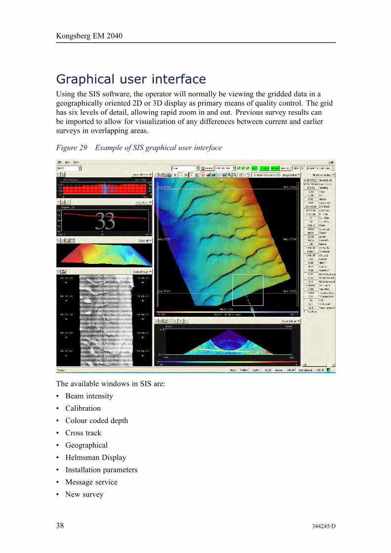
Graphical user interfaceUsing the SIS software, the operator will normally be viewing the gridded data in ageographically oriented 2D or 3D display as primary means of quality control. The gridhas six levels of detail, allowing rapid zoom in and out. Previous survey results canbe imported to allow for visualization of any differences between current and earliersurveys in overlapping areas.
Figure 29 Example of SIS graphical user interface
The available windows in SIS are:• Beam intensity• Calibration• Colour coded depth• Cross track• Geographical• Helmsman Display• Installation parameters• Message service• New survey
38 344245/D
Operational principals
• Numerical display• Planning module• PU sensor status• Runtime parameters• Runtime Parameters Mini• Scope display• Seabed image• Sensor Layout• Sound velocity profile• Stave display• Survey administration• Time series• Waterfall• Water column
Data loggingIt is of the utmost importance to ensure that all survey related data is logged in a safeway. The data is always stored on disk, and the geographical displays take data only fromthe disk. In this way, what the operator sees is what is safeguarded and already stored.The disks are optionally mounted in mobile storage bays, and may thus be removed forsecurity reasons or for transporting the acquired data. The stored data may be written toDVD at any time. The Firewire, SATA and the USB interfaces may be used for transferof data to external storage devices, such as disk or tape, according to user preferences.All data are also available on an external Ethernet.
The logged data sets include:• Raw sensor data• Beam ranges and beam pointing angles• Depth datagrams:
In each depth datagram range/angle observations from one ping have been mergedwith motion sensor data and current sound velocity profile to derive a rigoroussolution for vessel motion and ray bending, calculating sounding depth and positionas Cartesian coordinates. The depth datagrams are suited for immediate presentationin the geographical display.
• Seabed image data• System parameter settings• Water column data
344245/D 39

Kongsberg EM 2040
The data formats are public and published on the Kongsberg Maritime web site, ensuringthat the EM 2040 is a truly open solution, allowing third party or own software to bedeveloped for data processing.
40 344245/D
Post-processing
Post-processing
Post-processing optionsThe high quality data produced by the EM 2040 multibeam echo sounder is an excellentbasis for producing a complete description of the seabed in the form of charts, 3Ddisplays, combined bathymetry and acoustic imagery, seabed classification, etc.Kongsberg Maritime can deliver a complete set of products for post-processing EM 2040bathymetric data. Interfaces to other post-processing software is also available.
Caris HIPS/SIPS post-processingCaris is a well known suite of programs for processing of hydrographic data, developedand maintained by the Canadian company Caris. Caris can offer a complete processingenvironment, taking care of all steps until the final mapping products - both on paperand electronic form (S-57). Caris HIPS can import data from SIS and is integratedwith CUBE (Combined Uncertainty and Bathymetry Estimator, by University of NewHampshire).
QPS Fledermaus interactive 3D visualizationFledermaus by QPS is a high capacity, interactive software for visualizing largegeographical data sets, developed and maintained by the US based company IVS(Interactive Visualisation Systems). It also has interactive 3D functionality for editingsoundings, and is integrated with CUBE. It is an efficient tool for inspecting surveyresults, can also create fly-through videos.
344245/D 41
Kongsberg EM 2040
Geocap SeafloorGeocap Seafloor is a software package for multibeam data processing and seabedmapping. It offers a full range of bathymetric processing covering everything frominterfacing sensor data to final plot generation. The system has advanced processing,mapping and presentation features, including colours and sophisticated 3D functionality.Geocap Seafloor is developed by the Norwegian company Geocap AS.
HYPACKHYPACK by Hypack Inc. is a widely used hydrographic software package. It providesthe tools necessary to complete hydrographic, side scan and magnetometer surveyrequirements. HYPACK provides tools to design the survey, collect data, applycorrections to soundings, remove outliers, plot field sheets, export data to CAD, computevolume quantities, generate contours, create side scan mosaics and create/modifyelectronic charts.
42 344245/D
Customer support
Customer support
IntroductionAs a major supplier of Multibeam echo sounders with many years of experience,Kongsberg Maritime has developed a marketing and service organization tuned tocustomer needs.
InstallationAs part of the discussions with the client Kongsberg Maritime will - free of charge andwithout any obligations - give advice regarding the practical installation of the EM 2040system. We will also - upon request - prepare proposals for the supply of completeinstrument packages and/or systems. A project manager will be appointed to supervisethe delivery, installation and testing of larger instrumentation systems.
The installation and final testing of an EM 2040 system should be done according toKongsberg Maritime’s documentation. If required, Kongsberg Maritime field engineerscan be made available to:• Supervise the installation• Perform system check-out and final testing
Documentation and trainingThe EM 2040 is delivered with complete documentation for installation, operation andmaintenance. If required, the manuals may optionally be modified to reflect the actualsystem on the client’s vessel.
Kongsberg Maritime can conduct the training of operators and maintenance personnel tothe extent required by the client. Such training courses can take place on the vessel, onany of Kongsberg Maritime’s facilities, or any other location decided by the client.
344245/D 43
Kongsberg EM 2040
ServiceThe Kongsberg Maritime service department has a 24 hour duty arrangement, and canthus be contacted by telephone or by a dedicated support e-mail address at any time. Theservice department will assist in solving all problems that may be encountered during theoperation of the system, whether the problem is caused by finger trouble, insufficientdocumentation, software bugs or equipment breakdown.
FEMME – Forum for exchange of mutualmultibeam experienceA forum for users of Kongsberg Maritime’s multibeam echo sounder systems (FEMME),with the aim of improving communication both between the users and KongsbergMaritime, but also between the system users, is arranged at approximately 24 monthsintervals. Close to 100% user participation has been experienced at these meetings.
Warranty and maintenance contractThe normal warranty period of the EM 2040 is 24 months after delivery.
A system maintenance contract tailored to fit the needs of the client is available. Thiscontract can be defined so that it covers repair work only, or complete support forpreventive maintenance, repair work, and system upgrading of both hardware andsoftware as the system design is improved by Kongsberg Maritime.
The maintenance contract could also include a life-time warranty of transducers,upgrading of spare parts and documentation, and repeated or additional training courses.
Support informationIf you need technical support on the EM 2040 system you must contact aKongsberg Maritime office. A list of all our support offices is provided onhttp://www.km.kongsberg.com.
You can also contact our main support office in Norway.• Address: Strandpromenaden 50, 3190 Horten, Norway• Telephone: +47 33 02 38 00• Telephone, 24h: +47 815 35 355• Telefax: +47 33 04 76 19• E-mail address: [email protected]• Website: http://www.km.kongsberg.com
44 344245/D
Scope of supply and options
Scope of supply and options
Standard systemA basic EM 2040 Multibeam echo sounder delivery includes:1 Operator Station HWS with 19” LCD monitor2 Processing Unit configured according to chosen model3 Transducer arrays according to chosen model
• Transmit transducer• Receiver transducer(s)• 15 m transducer cables (standard length)
4 Transducer mounting plate5 Signal and control cables (standard length)
• Transducer cables• Ethernet cable between Processing Unit and Operator Station (5 m length)• Power cables (115 and/or 230 Vac)
6 All system software7 Technical manuals covering system installation, operation and maintenance
OptionsSystem options available include:• Mounting arrangement for over-the-side mounting of transducers which may include
integrated motion sensor, heading sensor and position sensor• 30 m or 50 m transducer cables• Non-standard connectors• Helmsman Display and/or additional monitors• Various software options• Removable disks• IP65 integrated keyboard and pointing device• Spare parts
344245/D 45
Kongsberg EM 2040
System integrationThe EM 2040 as presented in this product description is prepared for integration withother sensors to form a complete seabed mapping and inspection system. KongsbergMaritime can supply the EM 2040 either as a sub-system for integration by the user orother parties, or we can offer complete system solutions tailored to the user's need.
Additionally Kongsberg Maritime may deliver the EM 2040 as part of the completesurvey system. This may include integration with single beam echo sounders and/orother multibeam echo sounders, such as EM 710, EM 302 or EM 122, for seamlesscoverage of any depth range.
46 344245/D
Technical specifications
Technical specifications
Note
Kongsberg Maritime is engaged in continuous development of its products and reservesthe right to alter specifications without prior notice.
Interfaces• Serial lines with operator adjustable communication parameters for:
– Motion sensor (roll, pitch, heave and optionally heading) in format supported bysensors from the main suppliers like Kongsberg Seatex, Applanix, iXSEA, CodaOctopus and VT TSS
– Heading (gyro compass) in either NMEA 0183 HDT, SKR82/LR40 or SperryMk39 format
– Position in either Simrad 90, NMEA 0183 GGA or GGK format– External clock in NMEA 0183 ZDA format– Sound speed at transducer– Output of depth straight down in NMEA 0183 DPT format
• Interface for 1PPS (1 pulse per second) signal• Clock synchronization signal• Firewire interface for external data storage, printing or plotting• Parallel interface for post script colour graphics• Printer/plotter• Ethernet interface for velocity input required for Doppler compensation in chirp
mode. Formats by the following sensors are supported:– Kongsberg Seatex Seapath– Applanix POS MV– CodaOctopus F180– IXSEA Phins
• Ethernet interface for input of sound speed profile• Tide and echo sounder depths
344245/D 47
Kongsberg EM 2040
• Output of all data normally logged to disk
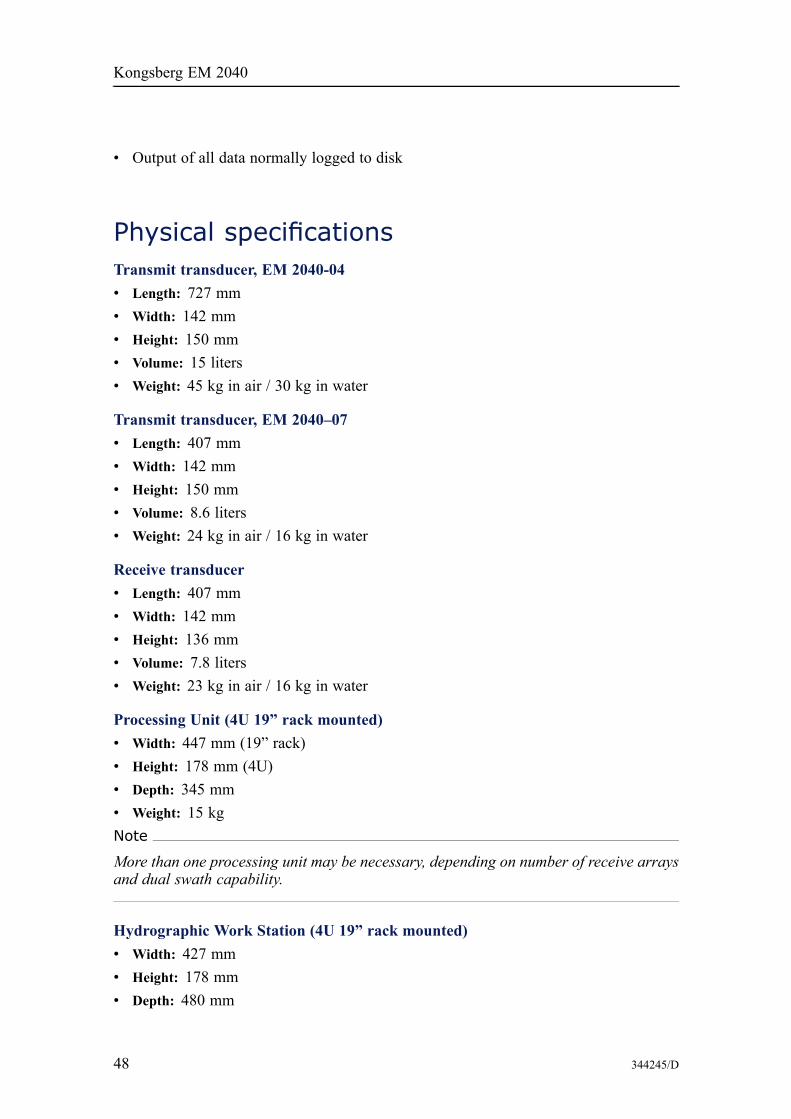
Physical specificationsTransmit transducer, EM 2040-04• Length: 727 mm• Width: 142 mm• Height: 150 mm• Volume: 15 liters• Weight: 45 kg in air / 30 kg in water
Transmit transducer, EM 2040–07• Length: 407 mm• Width: 142 mm• Height: 150 mm• Volume: 8.6 liters• Weight: 24 kg in air / 16 kg in water
Receive transducer• Length: 407 mm• Width: 142 mm• Height: 136 mm• Volume: 7.8 liters• Weight: 23 kg in air / 16 kg in water
Processing Unit (4U 19” rack mounted)• Width: 447 mm (19” rack)• Height: 178 mm (4U)• Depth: 345 mm• Weight: 15 kgNote
More than one processing unit may be necessary, depending on number of receive arraysand dual swath capability.
Hydrographic Work Station (4U 19” rack mounted)• Width: 427 mm• Height: 178 mm• Depth: 480 mm
48 344245/D
Technical specifications
• Weight: 20 kg
19” monitor• Width: 483 mm• Height: 444 mm• Depth: 68 mm• Weight: 12 kg
Transducer mounting plate, EM 2040–07• Length: 614 mm• Width: 407 mm• Height: 139 mm, including support pillars• Weight: 16 kg in air
Transducer mounting plate, EM 2040–04• Length: 615 mm• Width: 725 mm• Height: 139 mm, including support pillars• Weight: 23 kg in air
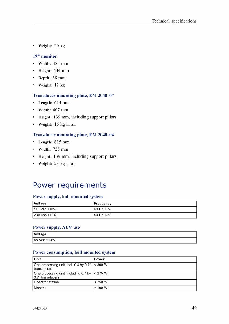
Power requirementsPower supply, hull mounted systemVoltage Frequency115 Vac ±10% 60 Hz ±5%
230 Vac ±10% 50 Hz ±5%
Power supply, AUV useVoltage48 Vdc ±10%
Power consumption, hull mounted systemUnit PowerOne processing unit, incl. 0.4 by 0.7°transducers
< 300 W
One processing unit, including 0.7 by0.7° transducers
< 275 W
Operator station < 250 W
Monitor < 100 W
344245/D 49
Kongsberg EM 2040
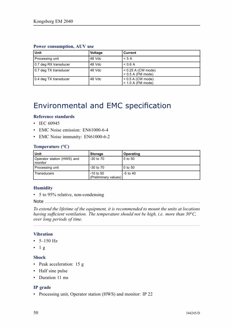
Power consumption, AUV useUnit Voltage CurrentProcessing unit 48 Vdc < 5 A
0.7 deg RX transducer 48 Vdc < 0.6 A
0.7 deg TX transducer 48 Vdc < 0.25 A (CW mode)< 0.5 A (FM mode)
0.4 deg TX transducer 48 Vdc < 0.5 A (CW mode)< 1.0 A (FM mode)
Environmental and EMC specificationReference standards• IEC 60945• EMC Noise emission: EN61000-6-4• EMC Noise immunity: EN61000-6-2
Temperature (°C)Unit Storage OperatingOperator station (HWS) andmonitor
-30 to 70 5 to 50
Processing unit -30 to 70 0 to 50
Transducers -10 to 50(Preliminary values)
-5 to 40
Humidity• 5 to 95% relative, non-condensingNote
To extend the lifetime of the equipment, it is recommended to mount the units at locationshaving sufficient ventilation. The temperature should not be high, i.e. more than 30°C,over long periods of time.
Vibration• 5–150 Hz• 1 g
Shock• Peak acceleration: 15 g• Half sine pulse• Duration 11 ms
IP grade• Processing unit, Operator station (HWS) and monitor: IP 22
50 344245/D
Technical specifications
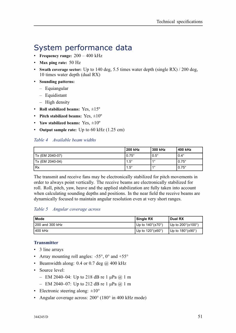
System performance data• Frequency range: 200 – 400 kHz• Max ping rate: 50 Hz• Swath coverage sector: Up to 140 deg, 5.5 times water depth (single RX) / 200 deg,
10 times water depth (dual RX)• Sounding patterns:
– Equiangular– Equidistant– High density
• Roll stabilized beams: Yes, ±15º• Pitch stabilized beams: Yes, ±10º• Yaw stabilized beams: Yes, ±10º• Output sample rate: Up to 60 kHz (1.25 cm)
Table 4 Available beam widths
200 kHz 300 kHz 400 kHzTx (EM 2040-07) 0.75° 0.5° 0.4°
Tx (EM 2040-04) 1.5° 1° 0.75°Rx 1.5° 1° 0.75°
The transmit and receive fans may be electronically stabilized for pitch movements inorder to always point vertically. The receive beams are electronically stabilized forroll. Roll, pitch, yaw, heave and the applied stabilization are fully taken into accountwhen calculating sounding depths and positions. In the near field the receive beams aredynamically focused to maintain angular resolution even at very short ranges.
Table 5 Angular coverage across
Mode Single RX Dual RX200 and 300 kHz Up to 140°(±70°) Up to 200°(±100°)400 kHz Up to 120°(±60°) Up to 180°(±90°)
Transmitter• 3 line arrays• Array mounting roll angles: -55°, 0° and +55°• Beamwidth along: 0.4 or 0.7 deg @ 400 kHz• Source level:
– EM 2040–04: Up to 218 dB re 1 μPa @ 1 m– EM 2040–07: Up to 212 dB re 1 μPa @ 1 m
• Electronic steering along: ±10°• Angular coverage across: 200° (180° in 400 kHz mode)
344245/D 51

Kongsberg EM 2040
Figure 30 TX transmission sector
Table 6 Pulse lengths
200 kHz 300 kHz 400 kHzCW FM CW FM CW FM
Normal mode 70/200/600 μs 3/12 ms 70/200/600 μs 2/6 ms 50/100/200 μs N/A
Single sector mode 35/70/150 μs 1.5 ms 35/70/150 μs 1.5 ms 25/50/100 μs N/A
Table 7 Max number of soundings per ping (dual swath)
200 kHz 300 kHz 400 kHzSingle system 800 800 800
Dual system 1600 1600 1600
Note
Single sector mode and short pulse length may give reduced number of soundings.
52 344245/D
Technical specifications
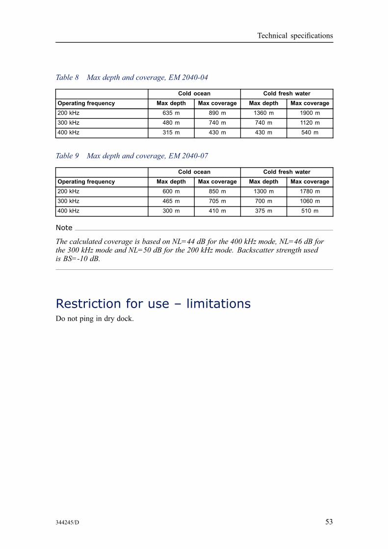
Table 8 Max depth and coverage, EM 2040-04
Cold ocean Cold fresh waterOperating frequency Max depth Max coverage Max depth Max coverage200 kHz 635 m 890 m 1360 m 1900 m
300 kHz 480 m 740 m 740 m 1120 m
400 kHz 315 m 430 m 430 m 540 m
Table 9 Max depth and coverage, EM 2040-07
Cold ocean Cold fresh waterOperating frequency Max depth Max coverage Max depth Max coverage200 kHz 600 m 850 m 1300 m 1780 m
300 kHz 465 m 705 m 700 m 1060 m
400 kHz 300 m 410 m 375 m 510 m
Note
The calculated coverage is based on NL=44 dB for the 400 kHz mode, NL=46 dB forthe 300 kHz mode and NL=50 dB for the 200 kHz mode. Backscatter strength usedis BS=-10 dB.
Restriction for use – limitationsDo not ping in dry dock.
344245/D 53
Kongsberg EM 2040
Company profile
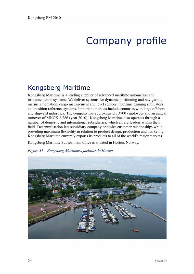
Kongsberg MaritimeKongsberg Maritime is a leading supplier of advanced maritime automation andinstrumentation systems. We deliver systems for dynamic positioning and navigation,marine automation, cargo management and level sensors, maritime training simulatorsand position reference systems. Important markets include countries with large offshoreand shipyard industries. The company has approximately 3700 employees and an annualturnover of MNOK 6.286 (year 2010). Kongsberg Maritime also operates through anumber of domestic and international subsidiaries, which all are leaders within theirfield. Decentralisation lets subsidiary company optimize customer relationships whileproviding maximum flexibility in relation to product design, production and marketing.Kongsberg Maritime currently exports its products to all of the world’s major markets.
Kongsberg Maritime Subsea main office is situated in Horten, Norway.
Figure 31 Kongsberg Maritime’s facilities in Horten
54 344245/D
Company profile
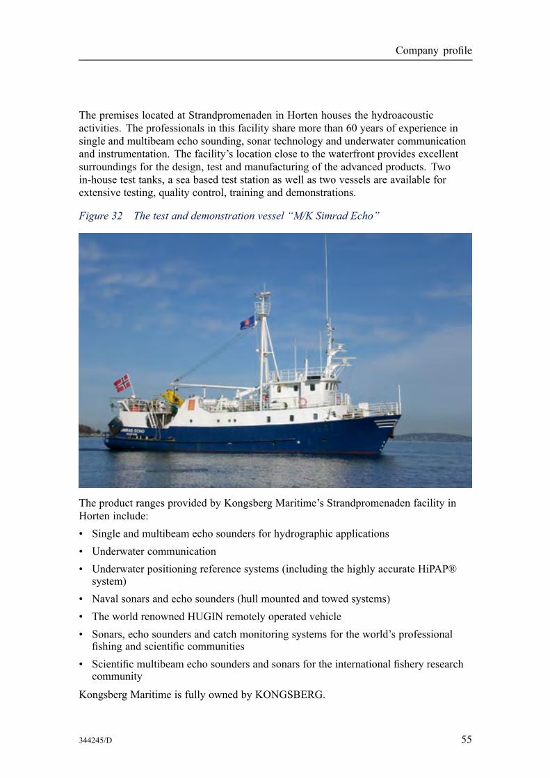
The premises located at Strandpromenaden in Horten houses the hydroacousticactivities. The professionals in this facility share more than 60 years of experience insingle and multibeam echo sounding, sonar technology and underwater communicationand instrumentation. The facility’s location close to the waterfront provides excellentsurroundings for the design, test and manufacturing of the advanced products. Twoin-house test tanks, a sea based test station as well as two vessels are available forextensive testing, quality control, training and demonstrations.
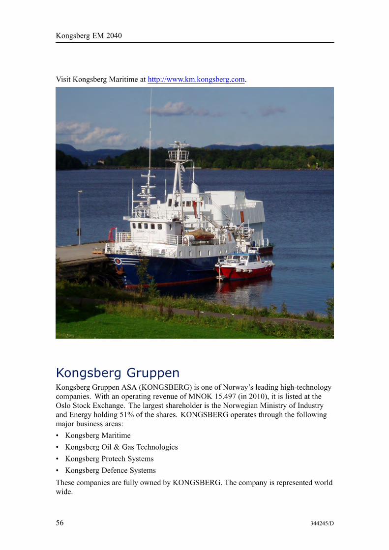
Figure 32 The test and demonstration vessel “M/K Simrad Echo”
The product ranges provided by Kongsberg Maritime’s Strandpromenaden facility inHorten include:• Single and multibeam echo sounders for hydrographic applications• Underwater communication• Underwater positioning reference systems (including the highly accurate HiPAP®
system)• Naval sonars and echo sounders (hull mounted and towed systems)• The world renowned HUGIN remotely operated vehicle• Sonars, echo sounders and catch monitoring systems for the world’s professional
fishing and scientific communities• Scientific multibeam echo sounders and sonars for the international fishery research
community
Kongsberg Maritime is fully owned by KONGSBERG.
344245/D 55
Kongsberg EM 2040
Visit Kongsberg Maritime at http://www.km.kongsberg.com.
Kongsberg GruppenKongsberg Gruppen ASA (KONGSBERG) is one of Norway’s leading high-technologycompanies. With an operating revenue of MNOK 15.497 (in 2010), it is listed at theOslo Stock Exchange. The largest shareholder is the Norwegian Ministry of Industryand Energy holding 51% of the shares. KONGSBERG operates through the followingmajor business areas:• Kongsberg Maritime• Kongsberg Oil & Gas Technologies• Kongsberg Protech Systems• Kongsberg Defence SystemsThese companies are fully owned by KONGSBERG. The company is represented worldwide.
56 344245/D


©2012 Kongsberg Maritime