elgin o’hare western access interchange- flyover...
TRANSCRIPT
11/16/2016Stanley Consultants1
ELGIN O’HARE WESTERN ACCESS
INTERCHANGE- FLYOVER RAMPS
Atalay Yargicoglu, Ph.D., P.E., S.E.
11/16/2016Stanley Consultants2
Outline
Project Overview
Bridge Type Investigation
Structural Analysis of Curved Girder Bridges
Flyover Ramp B-67
Midas Civil Analyses
Discussion of Results
References
Questions
11/16/2016Stanley Consultants3
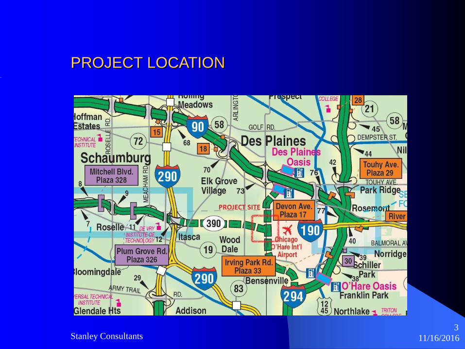
PROJECT LOCATION
11/16/2016Stanley Consultants4
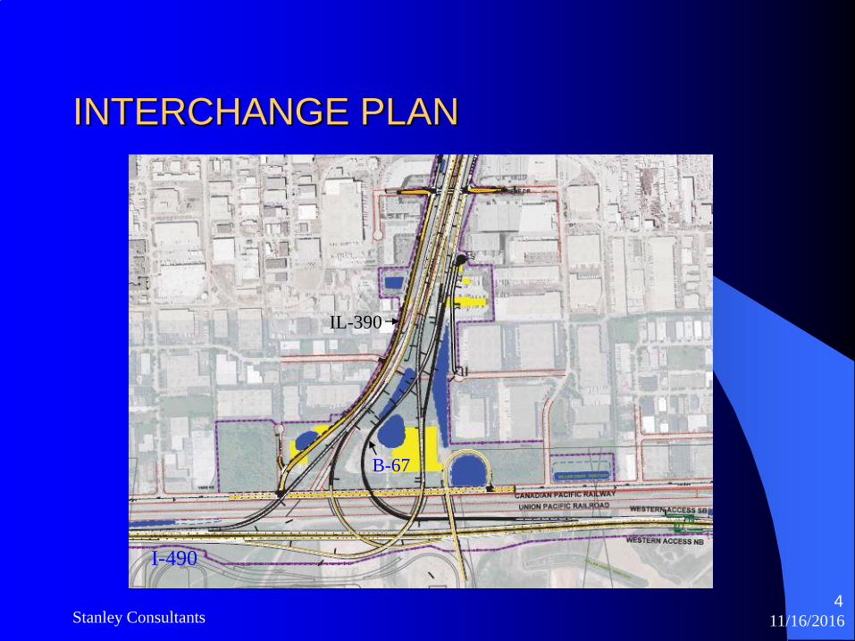
INTERCHANGE PLAN
B-67
I-490
IL-390
11/16/2016Stanley Consultants5
Bridge Type Investigation
Five Curved Girder Systems were considered
Steel plate girder
Steel tub girder (3 tub and 2 tub)
Concrete U-Girder (3 tub and 2 tub)
Concrete segmental
Hybrid (part steel spans – part concrete spans)
11/16/2016Stanley Consultants6
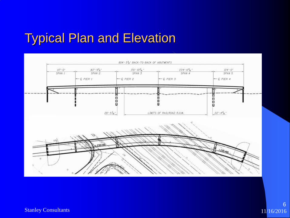
Typical Plan and Elevation

11/16/2016Stanley Consultants7
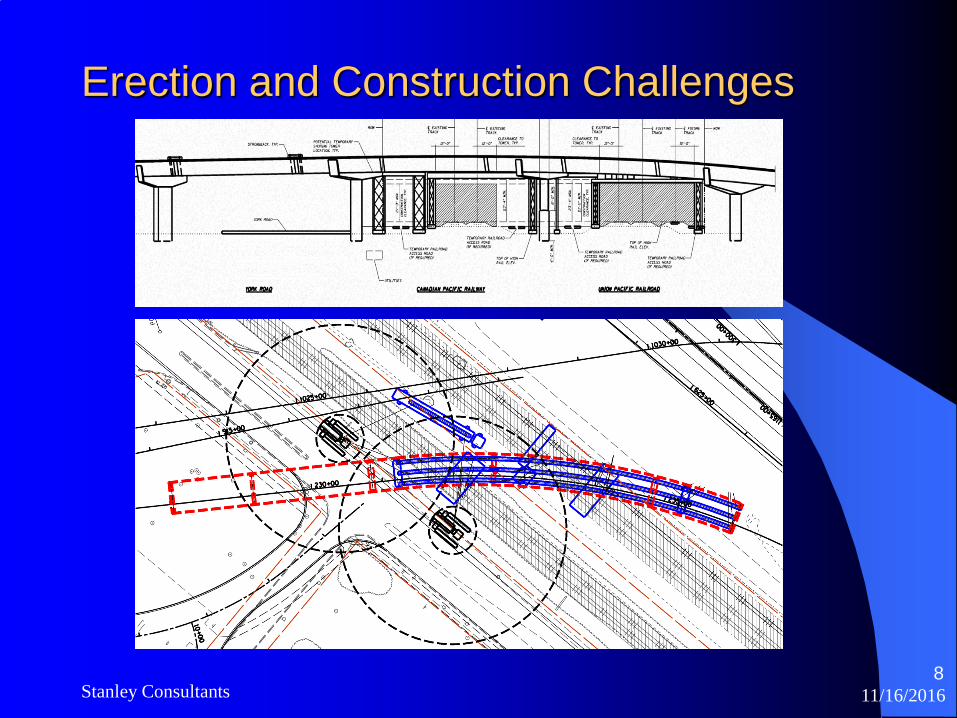
Erection and Construction Challenges
Active Class 1 Mainline Railroads
- UPRR 40+ trains /day
- All work must stop when train passes through (within 25’ each side of track)
Restricted Boom Heights due to FAA Requirements
Congested Site
- Limited Crane Locations and Girder Storage Areas
Shoring Towers
- 15’ Clearance to each side of Active Tracks
Girder Weight and Length Limitations for Erection & Transportation
11/16/2016Stanley Consultants8
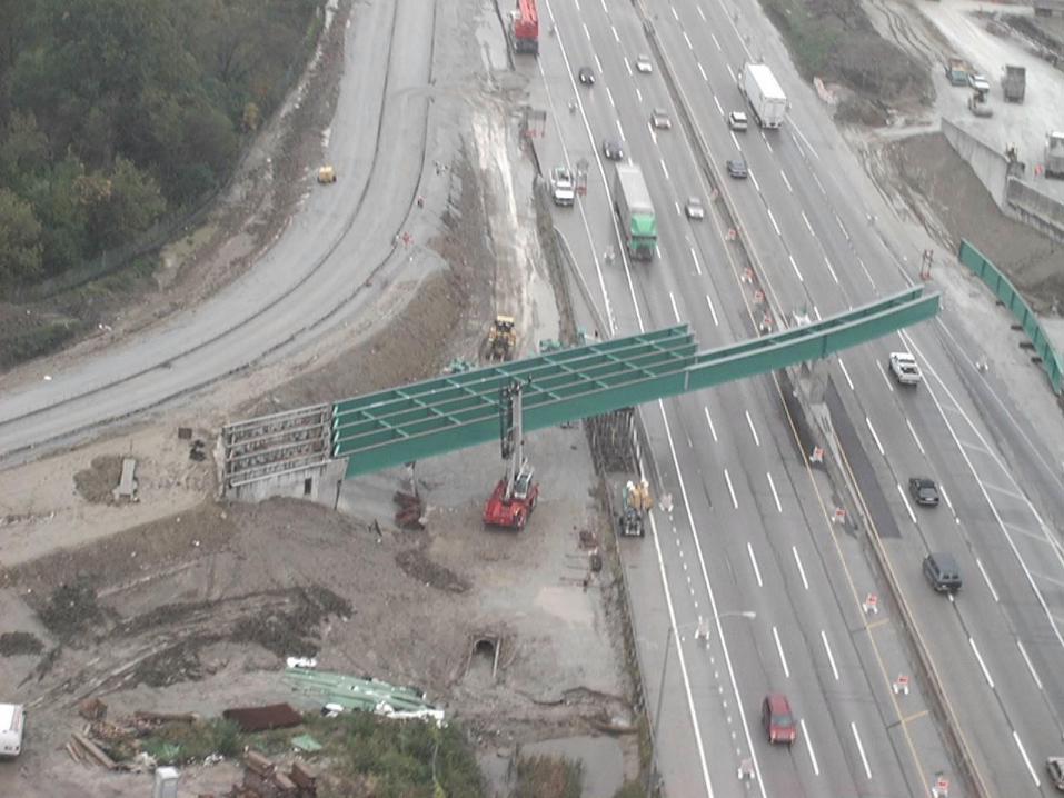
Erection and Construction Challenges

11/16/2016Stanley Consultants10
Curved Plate Girder
After extensive research into the design, fabrication, and erection
considerations Steel Curved Girder was found to be the best option.

11/16/2016Stanley Consultants11
Concrete U-GirderConcrete U-Girder alternate was further evaluated per Tollway request and
found to be a viable option but too risky for project schedule. Many
construction industry challenges need to be overcome:
- Precasters need to “tool-up” their operations. Requires time and investment.
- High capacity cranes and transport vehicles required.
- Non-Standard Shoring Towers/Straddlebents/Strongbacks needed to Support Splice Points
- Specialty Contractors and High Quality Control Required, etc.
11/16/2016Stanley Consultants12
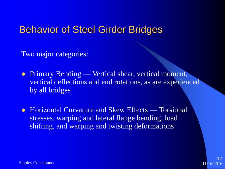
Behavior of Steel Girder Bridges
Two major categories:
Primary Bending — Vertical shear, vertical moment, vertical deflections and end rotations, as are experienced by all bridges
Horizontal Curvature and Skew Effects — Torsional stresses, warping and lateral flange bending, load shifting, and warping and twisting deformations
11/16/2016Stanley Consultants13
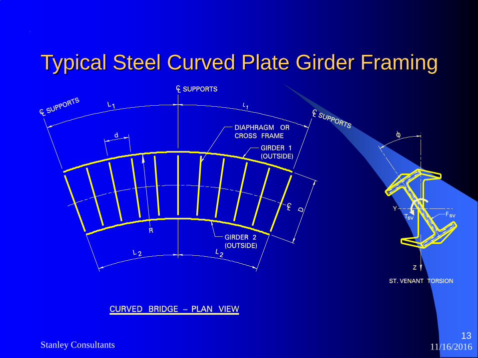
Typical Steel Curved Plate Girder Framing
11/16/2016Stanley Consultants14
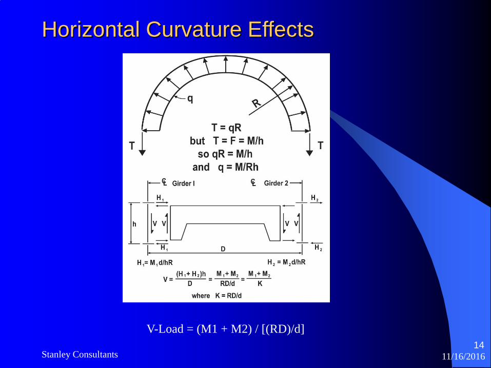
Horizontal Curvature Effects
V-Load = (M1 + M2) / [(RD)/d]

11/16/2016Stanley Consultants15
V-Load Method, 2-Step Process
1. Straighten out curved structure and apply vertical loads. Calculate V-Loads
2. Apply additional fictitious V-loads so that resulting internal forces are the same as those in the curved structure when subjected to vertical load only.
11/16/2016Stanley Consultants16
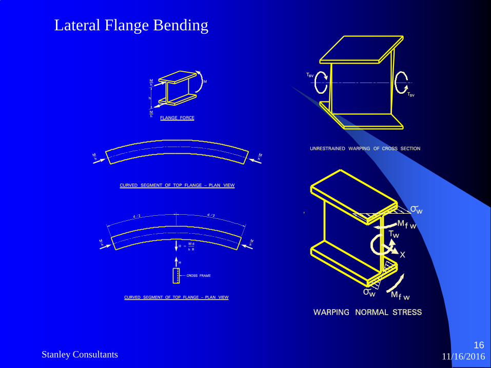
Lateral Flange Bending

11/16/2016Stanley Consultants17

11/16/2016Stanley Consultants18
Approximate Methods for Curvature Effects
When the global effects of curvature are neglected, lateral flange bending effects in curved girders must be accounted for by using approximate methods to address curvature. This is most commonly done using lateral flange bending equation:
M-lateral = M.d2 / 10 R h
where:
M-lateral = Lateral Flange Bending Moment
M = Primary Bending Moment
d = Cross frame spacing
R = Radius of Curvature
h = Depth of the Girder

11/16/2016Stanley Consultants19
Structural Analysis of Curved Girder BridgesStructural engineers currently have a wide array of approximate and refined analysis and design tools at their disposal.
Line-girder methods
- Bridge girders are analyzed individually for non-composite loads
- Composite loads distributed to all girders
- Live loads calculated by Distribution Factors
- V-Load Approximate Methods used for Curvature effects
- Approximate Methods used for Lateral Flange Bending due to Curvature effects
2D-grid and 2D-frame methods
- Girders and cross-frames are modeled as line elements
- Models interaction of girders and bracing system
- Vertical depth of structure is not considered
- Approximate Methods used for Lateral Flange Bending due to Curvature effects
11/16/2016Stanley Consultants20
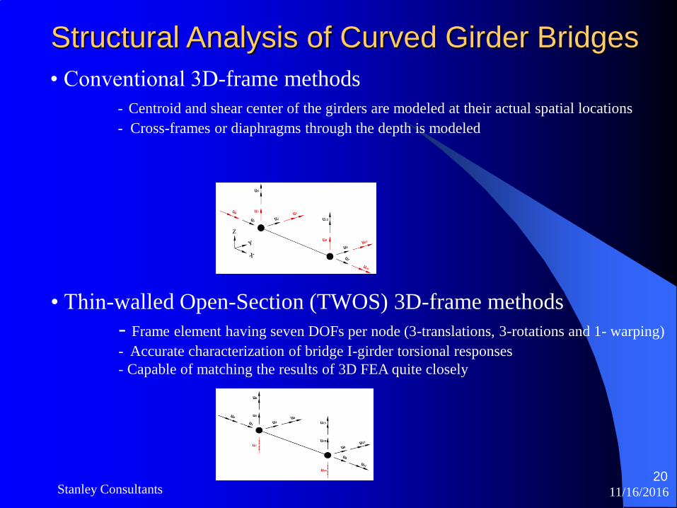
Structural Analysis of Curved Girder Bridges
• Conventional 3D-frame methods
- Centroid and shear center of the girders are modeled at their actual spatial locations
- Cross-frames or diaphragms through the depth is modeled
• Thin-walled Open-Section (TWOS) 3D-frame methods
- Frame element having seven DOFs per node (3-translations, 3-rotations and 1- warping)
- Accurate characterization of bridge I-girder torsional responses
- Capable of matching the results of 3D FEA quite closely
11/16/2016Stanley Consultants21
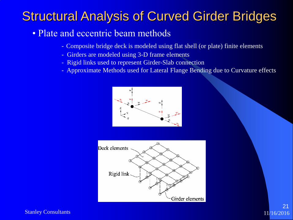
Structural Analysis of Curved Girder Bridges
• Plate and eccentric beam methods
- Composite bridge deck is modeled using flat shell (or plate) finite elements
- Girders are modeled using 3-D frame elements
- Rigid links used to represent Girder-Slab connection
- Approximate Methods used for Lateral Flange Bending due to Curvature effects
11/16/2016Stanley Consultants22
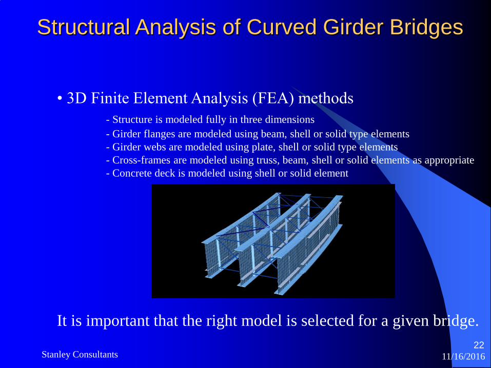
Structural Analysis of Curved Girder Bridges
• 3D Finite Element Analysis (FEA) methods
- Structure is modeled fully in three dimensions
- Girder flanges are modeled using beam, shell or solid type elements
- Girder webs are modeled using plate, shell or solid type elements
- Cross-frames are modeled using truss, beam, shell or solid elements as appropriate
- Concrete deck is modeled using shell or solid element
It is important that the right model is selected for a given bridge.
11/16/2016Stanley Consultants
23
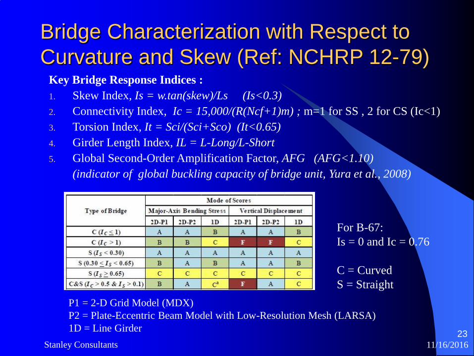
Bridge Characterization with Respect to
Curvature and Skew (Ref: NCHRP 12-79) Key Bridge Response Indices :
1. Skew Index, Is = w.tan(skew)/Ls (Is<0.3)
2. Connectivity Index, Ic = 15,000/(R(Ncf+1)m) ; m=1 for SS , 2 for CS (Ic<1)
3. Torsion Index, It = Sci/(Sci+Sco) (It<0.65)
4. Girder Length Index, IL = L-Long/L-Short
5. Global Second-Order Amplification Factor, AFG (AFG<1.10)
(indicator of global buckling capacity of bridge unit, Yura et al., 2008)
For B-67:
Is = 0 and Ic = 0.76
C = Curved
S = Straight
P1 = 2-D Grid Model (MDX)
P2 = Plate-Eccentric Beam Model with Low-Resolution Mesh (LARSA)
1D = Line Girder
11/16/2016Stanley Consultants24
Cross-Frame Detailing Considerations
Although AASHTO Article C6.7.2 (2010) states that engineers may need to consider the potential for any problematic locked-in stresses for horizontally curved I-girder bridges, engineers practically never include the inherent lack of fit in their structural analysis in current practice. However, the locked-in forces can significantly influence the girder layovers, the cross-frame forces, and the girder major-axis bending and/or flange lateral bending stresses in certain cases.
Since I-girders in curved bridges generally can be plumb only in one load condition, the cross-frames are fabricated to fit in the field as dictated by the girder erection loads and construction methods. The following approaches are employed:
- No Load Fit (NLF) Detailing
- Steel Dead Load Fit (SDLD) Detailing
-Total Dead Load Fit (TDLF) Detailing
For curved-radially supported bridges, NLF detailing is generally an effective approach since the locked in stresses due to SDLF and TDLF detailing are additive with the dead load stresses. The fact that the cross-frame forces tend to be smallest with NLF detailing.
NCHRP 12-79 research suggest that SDLF and TDLF detailing should be avoided in curved radially-supported bridges. Instead, if required, additional Cross-Frames should be employed to control the girder layovers within the spans.
11/16/2016Stanley Consultants25
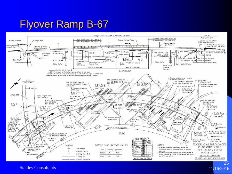
Flyover Ramp B-67
11/16/2016Stanley Consultants26
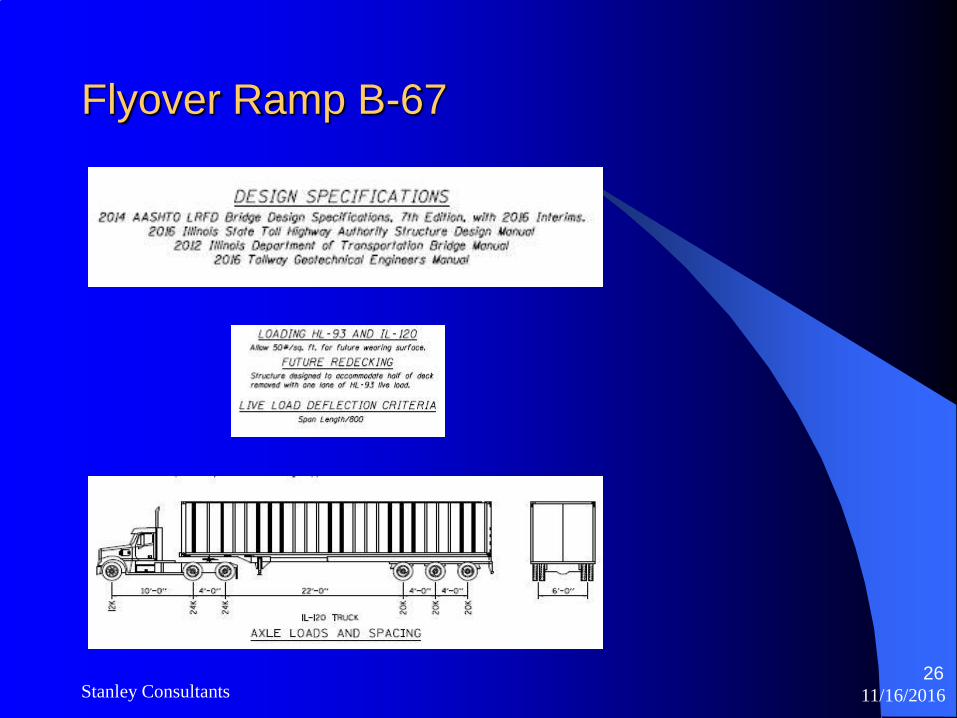
Flyover Ramp B-67

11/16/2016Stanley Consultants27
Flyover Ramp B-67
11/16/2016Stanley Consultants28
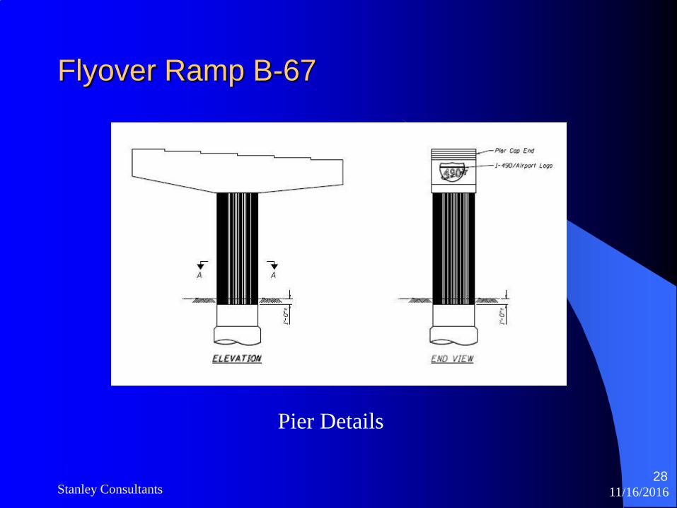
Flyover Ramp B-67
Pier Details
11/16/2016Stanley Consultants29
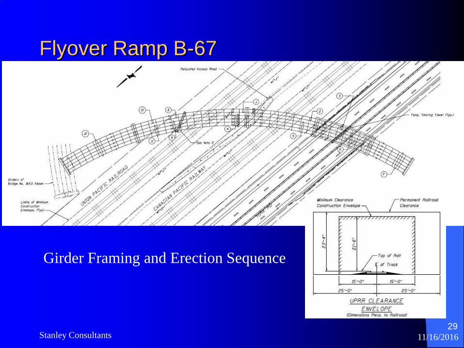
Flyover Ramp B-67
Girder Framing and Erection Sequence
11/16/2016Stanley Consultants30
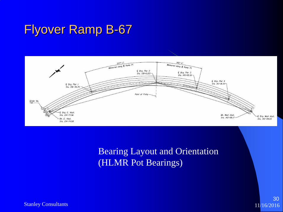
Flyover Ramp B-67
Bearing Layout and Orientation
(HLMR Pot Bearings)
11/16/2016Stanley Consultants31
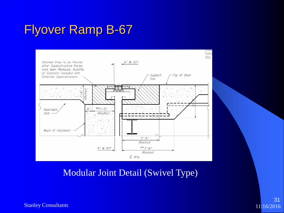
Flyover Ramp B-67
Modular Joint Detail (Swivel Type)
11/16/2016Stanley Consultants32
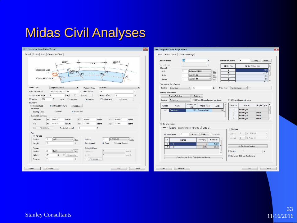
Midas Civil Analyses
Midas Civil program used to investigate the lateral response of
the structure to investigate:
- Pier Deflections
- Modular Joint Movements
- Lateral Reactions at Abutments
Model Summary:
Steel Composite Wizard
Drilled Shafts at Piers
Soil Springs
Additional Load Cases for Wind, Braking, and Temperature
11/16/2016Stanley Consultants33
Midas Civil Analyses

11/16/2016Stanley Consultants34
Midas Civil Analyses
11/16/2016Stanley Consultants35
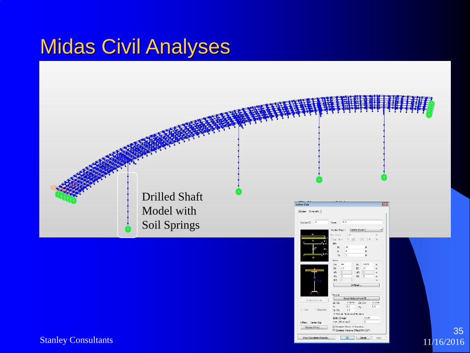
Midas Civil Analyses
Drilled Shaft
Model with
Soil Springs
11/16/2016Stanley Consultants36
Midas Civil Analyses
11/16/2016Stanley Consultants37
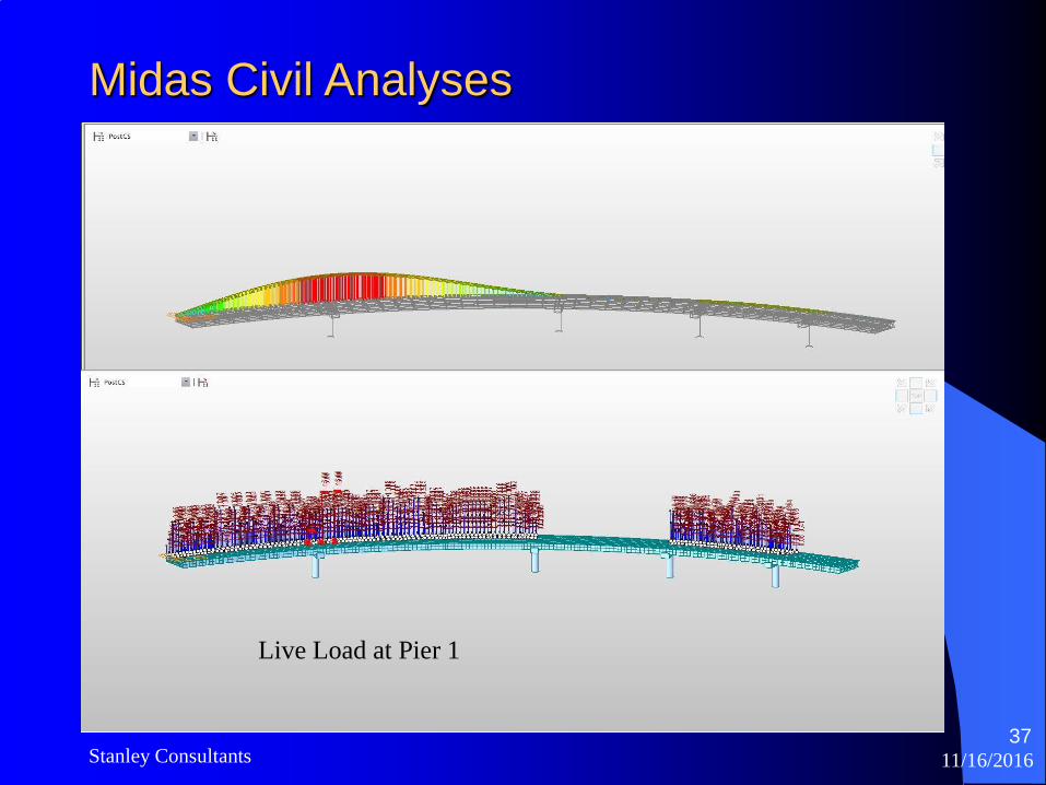
Midas Civil Analyses
Live Load at Pier 1

11/16/2016Stanley Consultants38
Midas Civil Analyses

11/16/2016Stanley Consultants39
Bearing Orientation
11/16/2016Stanley Consultants40
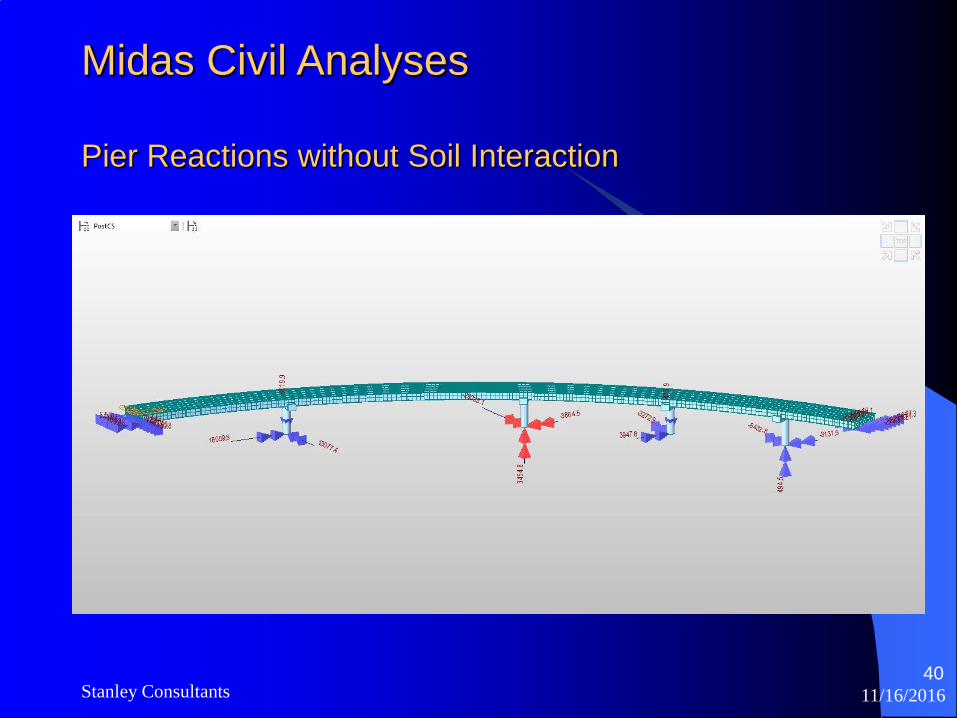
Midas Civil Analyses
Pier Reactions without Soil Interaction
11/16/2016Stanley Consultants41
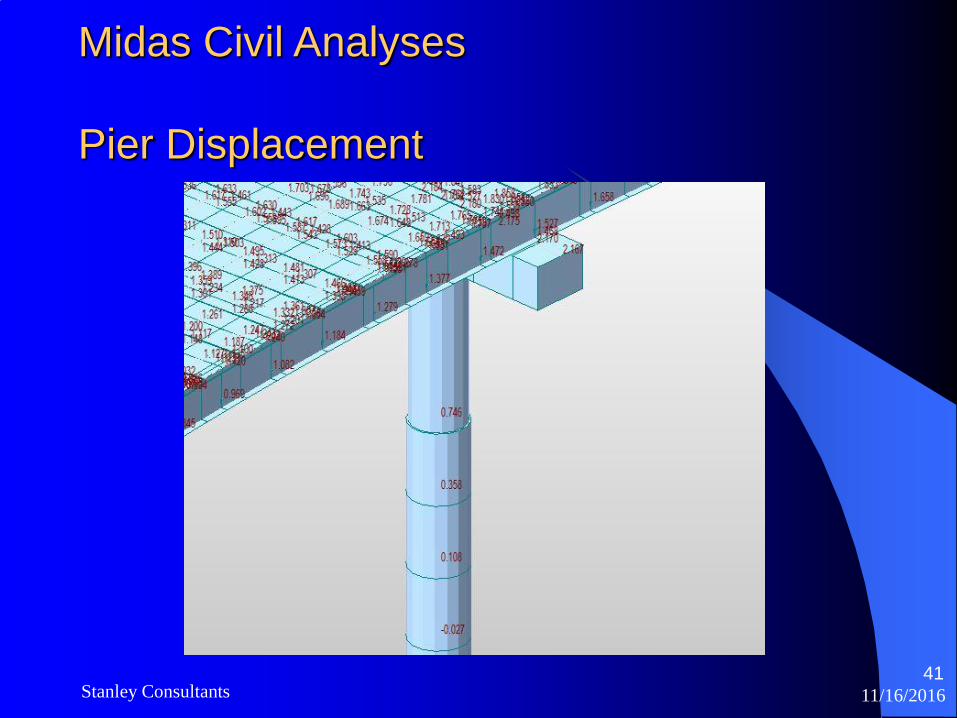
Midas Civil Analyses
Pier Displacement
11/16/2016Stanley Consultants42
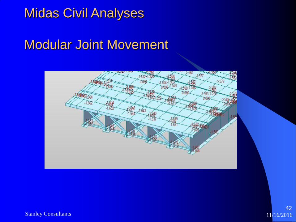
Midas Civil Analyses
Modular Joint Movement
11/16/2016Stanley Consultants43
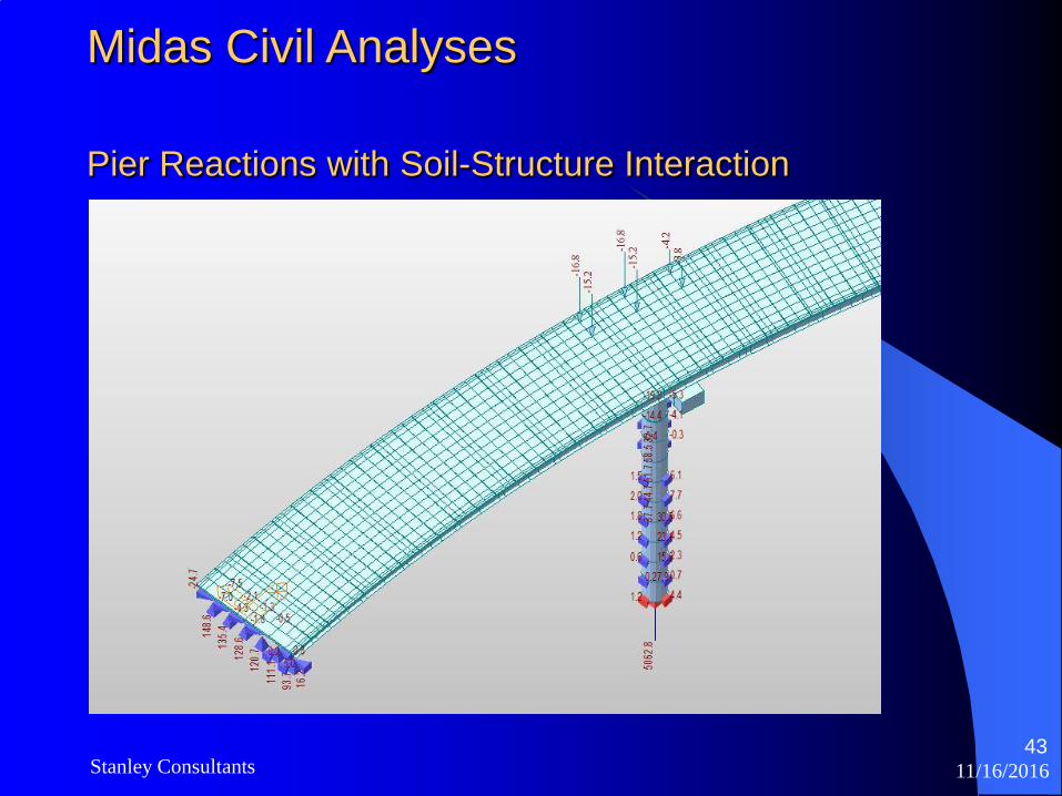
Midas Civil Analyses
Pier Reactions with Soil-Structure Interaction
11/16/2016Stanley Consultants44
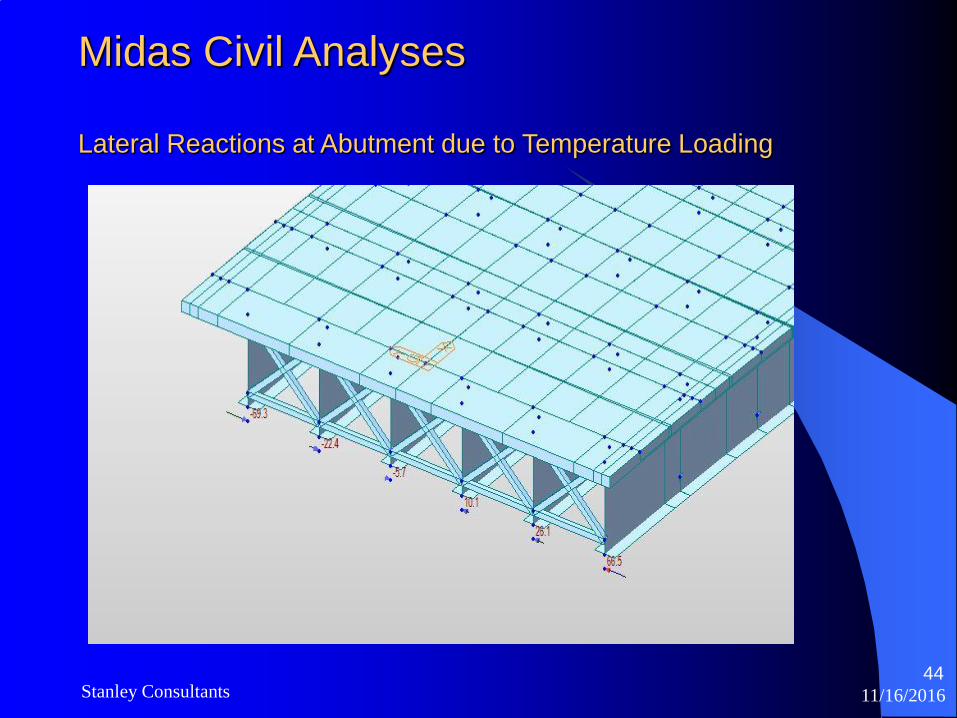
Midas Civil Analyses
Lateral Reactions at Abutment due to Temperature Loading
11/16/2016Stanley Consultants45
Midas Civil Analyses
Discussion of Results
1. Lateral reactions due to Live load effects were distributed to
all supports. This reduced the pier deflections approximately
by a factor of 2 as compared to decoupled analysis using
tributary span.
2. Lateral reactions at abutments increased approximately 25%.
3. Joints movements were about the same as simple calculations
based on expansion length.

11/16/2016Stanley Consultants46
References1. American Association of State Highway Transportation Officials (AASHTO), LRFD
Bridge Design Specifications, 7th Edition, 2016.
2. American Association of State Highway Transportation Officials (AASHTO), Guide
Specifications for Horizontally Curved Steel Girder Highway Bridges, 2003.
3. FHWA Steel Bridge Design Handbook, Structural Analysis, Publication No. FHWA-IF-
12-052 - Vol. 8
4. TRB’s National Cooperative Highway Research Program (NCHRP) Report 725:
Guidelines for Analysis Methods and Construction Engineering of Curved and Skewed
Steel Girder Bridges
5. TRB’s National Cooperative Highway Research Program (NCHRP) Report 424:
Improved Design Specifications for Horizontally Curved Steel Girder Highway Bridges
6. TRB’s National Cooperative Highway Research Program (NCHRP) Report 12-79:
Evaluation of Analytical Methods for Construction Engineering of Curved and Skewed
Steel Girder Bridges
USS Structural Report, “Analysis and Design of Horizontally Curved Steel Bridge Girders”
(USS, 1965).

11/16/2016Stanley Consultants47
Questions ?