electronic micrometer mu-checker sensor systems...electronic micrometer mu-checker sensor systems...
TRANSCRIPT
Electronic MicrometerMu-Checker
Sens
or S
yste
ms
Catalog No. E13003(2)
2
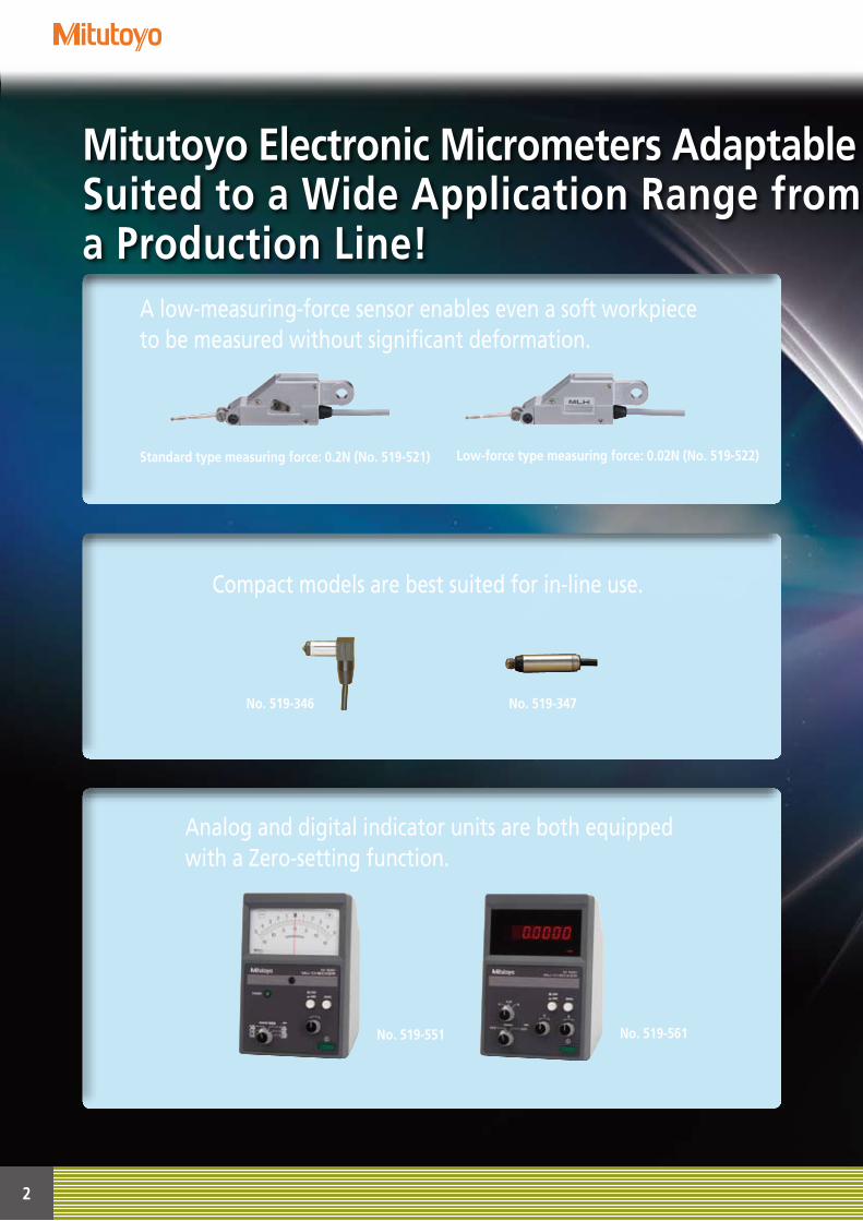
Mitutoyo Electronic Micrometers Adaptable to Customer DemandsSuited to a Wide Application Range from the Inspection Room to Building into a Production Line!
A low-measuring-force sensor enables even a soft workpiece to be measured without significant deformation.
Compact models are best suited for in-line use.
Analog and digital indicator units are both equipped with a Zero-setting function.
Standard type measuring force: 0.2N (No. 519-521)
No. 519-346
No. 519-551
Low-force type measuring force: 0.02N (No. 519-522)
No. 519-347
No. 519-561
3
Mitutoyo Electronic Micrometers Adaptable to Customer DemandsSuited to a Wide Application Range from the Inspection Room to Building into a Production Line!
Probe
AmplifierDigital indicator
Analog indicator
Waveformshapingcircuit
Synchronouswave-shaping
circuitAmplifier
circuit
A/Dconverter
Outputunit
Analog output(to a recorder, etc.)
Digital output BCD output RS-232C outputOscillator
circuitPower supply circuitConstant-voltagecircuit
Low-passfilter
199.9
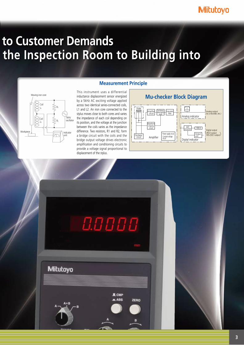
Mu-checker Block DiagramMoving iron core
oscillator
Indicator unit
Workpiece
Coil
Coil
L1
L2
R1
5kHzR2
This instrument uses a different ia l inductance displacement sensor energized by a 5kHz AC exciting voltage applied across two identical series-connected coils, L1 and L2. An iron core connected to the stylus moves close to both cores and varies the impedance of each coil depending on its position, and the voltage at the junction between the coils varies as the impedance difference. Two resistors, R1 and R2, form a bridge circuit with the coils and the bridge output voltage drives electronic amplification and conditioning circuits to provide a voltage signal proportional to displacement of the stylus.
Measurement Principle
4
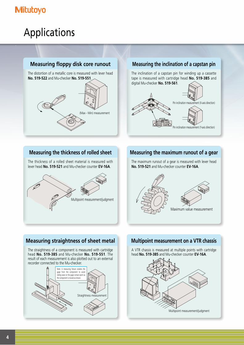
Measuring the inclination of a capstan pinMeasuring floppy disk core runout
Measuring the maximum runout of a gearMeasuring the thickness of rolled sheet
Multipoint measurement on a VTR chassisMeasuring straightness of sheet metal
Applications
The distortion of a metallic core is measured with lever head No. 519-522 and Mu-checker No. 519-551.
The thickness of a rolled sheet material is measured with lever head No. 519-521 and Mu-checker counter EV-16A.
The maximum runout of a gear is measured with lever head No. 519-521 and Mu-checker counter EV-16A.
The straightness of a component is measured with cartridge head No. 519-385 and Mu-checker No. 519-551. The result of each measurement is also plotted out to an external recorder connected to the Mu-checker.
A VTR chassis is measured at multiple points with cartridge head No. 519-385 and Mu-checker counter EV-16A.
振れ測定
(Max - Min) measurement
The inclination of a capstan pin for winding up a cassette tape is measured with cartridge head No. 519-385 and digital Mu-checker No. 519-561.
Pin inclination measurement (X-axis direction)
Pin inclination measurement (Y-axis direction)
厚さ測定
Multipoint measurement/judgment
最大値測定
Maximum value measurement
Straightness measurement
Note: A measuring fixture isolates the gage from the component to avoid sliding wear on the gage contact point as the component is moved as shown.
Multipoint measurement/judgment
5
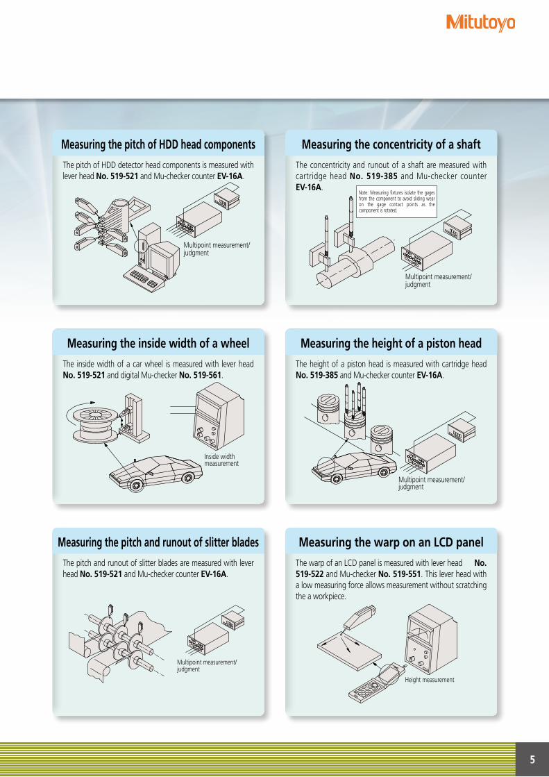
Measuring the concentricity of a shaftMeasuring the pitch of HDD head components
Measuring the height of a piston headMeasuring the inside width of a wheel
Measuring the warp on an LCD panelMeasuring the pitch and runout of slitter blades
The pitch of HDD detector head components is measured with lever head No. 519-521 and Mu-checker counter EV-16A.
The inside width of a car wheel is measured with lever head No. 519-521 and digital Mu-checker No. 519-561.
The height of a piston head is measured with cartridge head No. 519-385 and Mu-checker counter EV-16A.
The pitch and runout of slitter blades are measured with lever head No. 519-521 and Mu-checker counter EV-16A.
The warp of an LCD panel is measured with lever head No. 519-522 and Mu-checker No. 519-551. This lever head with a low measuring force allows measurement without scratching the a workpiece.
The concentricity and runout of a shaft are measured with cartridge head No. 519-385 and Mu-checker counter EV-16A.
Multipoint measurement/judgment
Multipoint measurement/judgment
Note: Measuring fixtures isolate the gages from the component to avoid sliding wear on the gage contact points as the component is rotated.
振れ測定/判定
Inside width measurement
Multipoint measurement/judgment
多点測定/判定
Multipoint measurement/judgment
平面度測定/判定
Height measurement
6
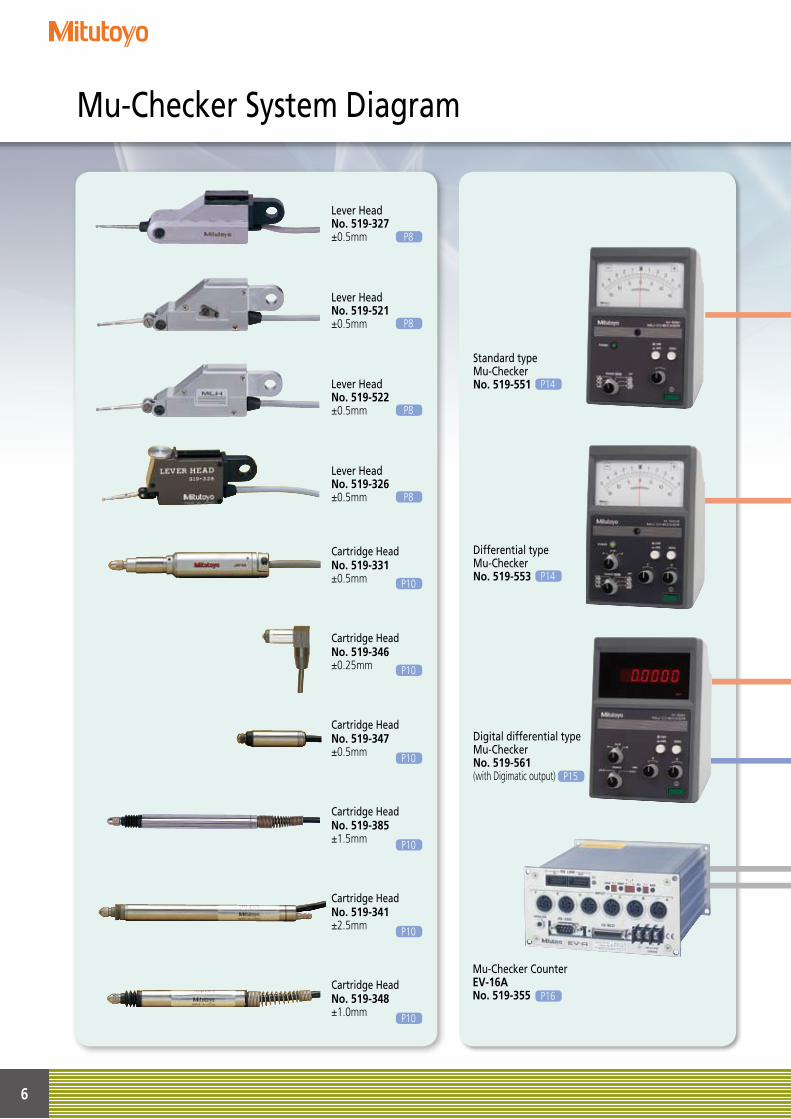
Mu-Checker System Diagram
Differential type Mu-CheckerNo. 519-553
Digital differential type Mu-CheckerNo. 519-561(with Digimatic output)
Mu-Checker CounterEV-16ANo. 519-355
Lever HeadNo. 519-521±0.5mm P8
Lever HeadNo. 519-327±0.5mm P8
Lever HeadNo. 519-522±0.5mm P8
Lever HeadNo. 519-326±0.5mm P8
Cartridge HeadNo. 519-331±0.5mm P10
Cartridge HeadNo. 519-347±0.5mm P10
Cartridge HeadNo. 519-385±1.5mm P10
Cartridge HeadNo. 519-341±2.5mm P10
Cartridge HeadNo. 519-348±1.0mm P10
Cartridge HeadNo. 519-346±0.25mm P10
P16
P15
P14
Standard type Mu-CheckerNo. 519-551 P14
7
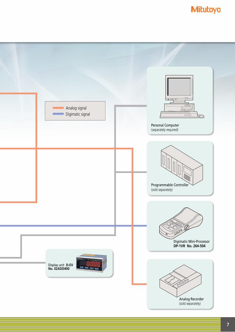
Analog signalDigimatic signal
Personal Computer(separately required)
Programmable Controller(sold separately)
Digimatic Mini-ProcessorDP-1VR No. 264-504
Analog Recorder(sold separately)
Display unit D-EVNo. 02ADD400
8
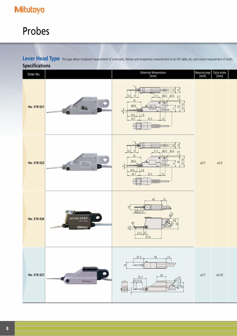
Specifications
Order No. External dimensions[mm]
Measuring range[mm]
Stylus stroke[mm]
Measuring force
Linearity[%]
Bearing unit structure
Remarks/Interchangeable stylus
No. 519-521
±0.5 ±0.6
Approx. 0.2N
±0.3
Pivot bearing type
Measuring direction changed with the forward reverse lever
No. 520940 (ø1)No. 520939 (ø2)No. 520938 (ø3)
No. 519-522 Approx. 0.02N Pivot bearing type
Low measuring force No. 520940 (ø1)No. 520939 (ø2)No. 520938 (ø3)
No. 519-326 Approx. 0.15N ±0.3 Parallel leaf spring
type
The measuring force is adjustable with the upper dial.No need for displayed value correction when stylus makes an angle with surface
No. 102824 (ø1)No. 102832 (ø2)No. 102826 (ø3)Note: Only the ø2 stylus tip is a standard accessory.
No. 519-327 ±0.5 ±0.65 Approx. 0.15N ±0.5 Pivot bearing type
No need for change of measuring direction due to no-clutch type
No. 102824 (ø1)No. 102832 (ø2)No. 102826 (ø3)Note: Only the ø2 stylus tip is a standard accessory.
Probes
This type allows multipoint measurement of small parts, flatness and straightness measurement on an X/Y table, etc. and runout measurement of shafts.Lever Head Type
43
6.5 9 7
22.567.6
5.5
ø2 R7
13
826
ø6.5
4.5
14
35
145
5.824.9
7
17
261.
75
(27
.75)
19 21.3
41330.7 52.3
9.2
φ6.6
φ6.5 φ14
35
1455.824.9
7
17
261.
75
(27
.75)
19 21.3
4
1330.7 52.3
9.2
φ6.6
φ6.5 φ14
ø6.5
16
7
24
2432.3
25.3 56 13
15.86.5
R7
73.
5
9
Specifications
Order No. External dimensions[mm]
Measuring range[mm]
Stylus stroke[mm]
Measuring force
Linearity[%]
Bearing unit structure
Remarks/Interchangeable stylus
No. 519-521
±0.5 ±0.6
Approx. 0.2N
±0.3
Pivot bearing type
Measuring direction changed with the forward reverse lever
No. 520940 (ø1)No. 520939 (ø2)No. 520938 (ø3)
No. 519-522 Approx. 0.02N Pivot bearing type
Low measuring force No. 520940 (ø1)No. 520939 (ø2)No. 520938 (ø3)
No. 519-326 Approx. 0.15N ±0.3 Parallel leaf spring
type
The measuring force is adjustable with the upper dial.No need for displayed value correction when stylus makes an angle with surface
No. 102824 (ø1)No. 102832 (ø2)No. 102826 (ø3)Note: Only the ø2 stylus tip is a standard accessory.
No. 519-327 ±0.5 ±0.65 Approx. 0.15N ±0.5 Pivot bearing type
No need for change of measuring direction due to no-clutch type
No. 102824 (ø1)No. 102832 (ø2)No. 102826 (ø3)Note: Only the ø2 stylus tip is a standard accessory.
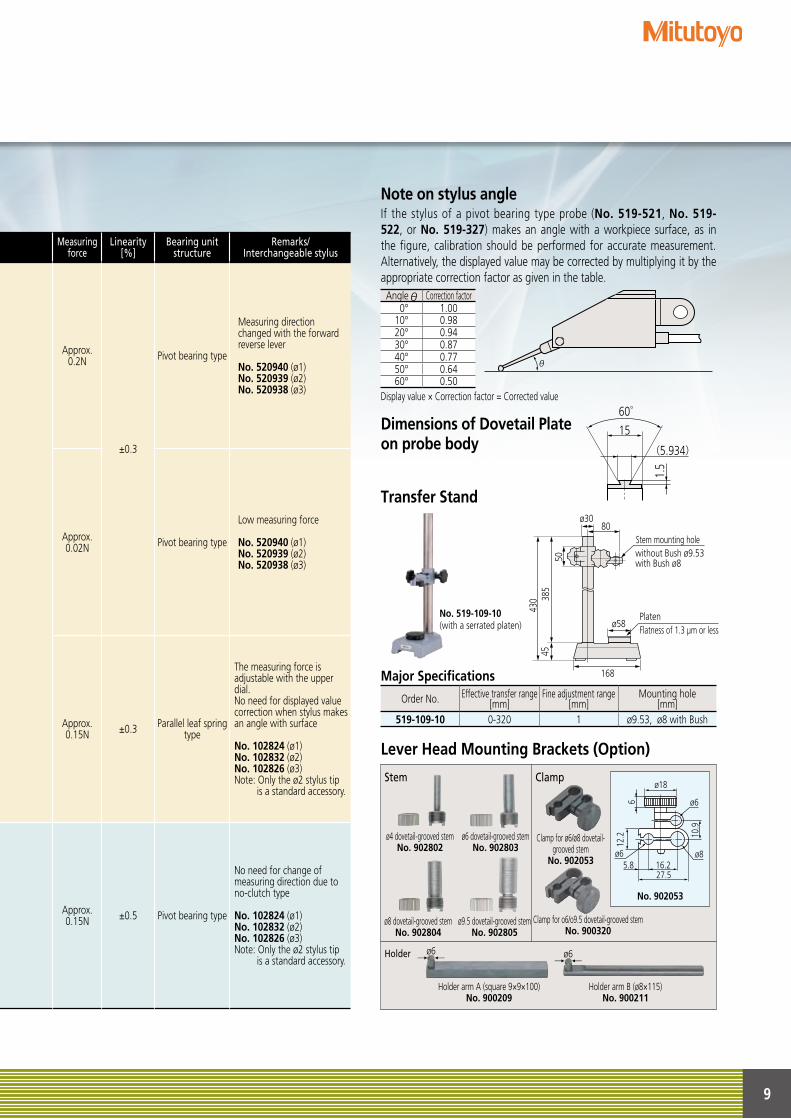
Note on stylus angleIf the stylus of a pivot bearing type probe (No. 519-521, No. 519-522, or No. 519-327) makes an angle with a workpiece surface, as in the figure, calibration should be performed for accurate measurement. Alternatively, the displayed value may be corrected by multiplying it by the appropriate correction factor as given in the table.
Display value × Correction factor = Corrected value
Dimensions of Dovetail Plate on probe body
Transfer Stand
Lever Head Mounting Brackets (Option)クランプ
No. 519-109-10(with a serrated platen)
ø4 dovetail-grooved stemNo. 902802
Clamp for ø6/ø8 dovetail-grooved stem
No. 902053
Holder arm A (square 9×9×100)No. 900209
Holder arm B (ø8×115) No. 900211
Clamp for o6/o9.5 dovetail-grooved stemNo. 900320
ø6 dovetail-grooved stemNo. 902803
ø8 dovetail-grooved stemNo. 902804
ø9.5 dovetail-grooved stemNo. 902805
No. 902053
Stem Clamp
Holder
This type allows multipoint measurement of small parts, flatness and straightness measurement on an X/Y table, etc. and runout measurement of shafts.
Angle Correction factor0° 1.00
10° 0.9820° 0.9430° 0.8740° 0.7750° 0.6460° 0.50
θ
60゜
15
1.5
(5.934)
80
44
160(W)×100(D)
4059
65
635
4516
6043
0
ø30
ø8
ø8
110
ø30
70
215
焼入鋼平面度1μm以下
ø58
Platen
Stem mounting hole
ø30
without Bush ø9.53 with Bush ø850
385
4543
0
ø58
80
168
Flatness of 1.3 µm or less
Major Specifications
Order No. Effective transfer range[mm]
Fine adjustment range[mm]
Mounting hole[mm]
519-109-10 0-320 1 ø9.53, ø8 with Bush
ø18
ø6 ø8
ø6
16.227.5
5.8
12.2
6
10.9
扌ø6扌 扌
ø6扌
10
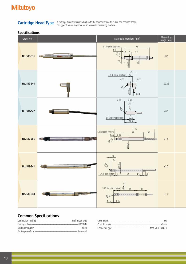
A cartridge head type is easily built-in to the equipment due to its slim and compact shape.This type of sensor is optimal for an automatic measuring machine.
Cartridge Head Type
Common SpecificationsConnection method —————————————————————— Half-bridge typeExciting voltage ——————————————————————————————3.0VRMSExciting frequency —————————————————————————————— 5kHzExciting waveform ——————————————————————————— Sinusoidal
Cord length——————————————————————————————————— 2mCord thickness ——————————————————————————————— ø4mmConnector type ——————————————————————— Mas-5100 (DIN5P)
SpecificationsOrder No. External dimensions [mm] Measuring
range [mm]Maximum stylus stroke
[mm] Measuring force Linearity [%] * Dust-proof rubber boot Bearing unit structure Remarks/Interchangeable stylus
No. 519-331 ±0.5 ±0.65 0.25N ±0.5 No Plain type Low measuring force
Accepts interchangeable styli
for dial indicatorsM2.5×5
No. 519-346
3.5 (0-point position)
ø8h6
0.26 0.34
0 -0.0
09R1.25
ø3.5
2512
±0.25 +0.34–0.26 0.7N ±0.3 No Linear ball bearing type
Compact typeSuitable for inside-
diameter measurement
Dedicated stylus usedNon-interchangeable
No. 519-347
6.8 (0-point position) 22.534.5
ø8h6
0.65 0.85
0 -0.0
09
R1.5±0.5 +0.85
–0.65 0.7N ±0.3 Yes Linear ball bearing type Compact type
No. 519-385
112.358 31
1.65 2.35
SR 1.5
21.65 (0-point position)
φ8h
6 0 -0.0
09
±1.5 +2.35–1.65 0.7N ±0.3 Yes Linear ball bearing type Standard type with
cable strain-relief
Accepts interchangeable styli
for dial indicatorsM2.5×5
No. 519-341
14.75 (0-point position) 712 84.5
ø8h6
2.83.2
0 -0.0
09
R1.5 ±2.5 +3.2–2.8 0.9N ±0.5 Yes Linear ball bearing type Standard type
No. 519-348
15.25 (0-point position) 48 31ø8h6
1.15 1.35
0 -0.0
09
R1.5 ±1.0 +1.35–1.15 0.7N ±0.3 Yes Linear ball bearing type Standard type with
cable strain-relief
8.1 (0-point position) 71
5 15 4.5
7.3
R1.5
ø12
ø8h6
1.3
0 -0.0
09
11
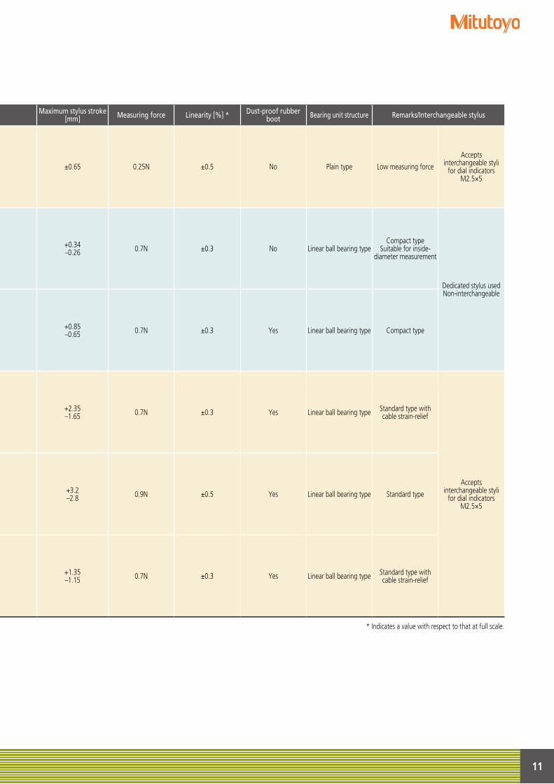
SpecificationsOrder No. External dimensions [mm] Measuring
range [mm]Maximum stylus stroke
[mm] Measuring force Linearity [%] * Dust-proof rubber boot Bearing unit structure Remarks/Interchangeable stylus
No. 519-331 ±0.5 ±0.65 0.25N ±0.5 No Plain type Low measuring force
Accepts interchangeable styli
for dial indicatorsM2.5×5
No. 519-346 ±0.25 +0.34–0.26 0.7N ±0.3 No Linear ball bearing type
Compact typeSuitable for inside-
diameter measurement
Dedicated stylus usedNon-interchangeable
No. 519-347 ±0.5 +0.85–0.65 0.7N ±0.3 Yes Linear ball bearing type Compact type
No. 519-385 ±1.5 +2.35–1.65 0.7N ±0.3 Yes Linear ball bearing type Standard type with
cable strain-relief
Accepts interchangeable styli
for dial indicatorsM2.5×5
No. 519-341 ±2.5 +3.2–2.8 0.9N ±0.5 Yes Linear ball bearing type Standard type
No. 519-348 ±1.0 +1.35–1.15 0.7N ±0.3 Yes Linear ball bearing type Standard type with
cable strain-relief
* Indicates a value with respect to that at full scale.
12
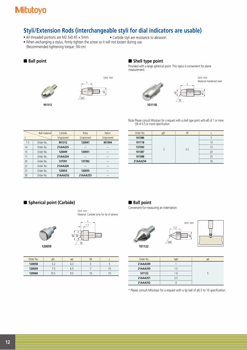
• Carbide styli are resistance to abrasion.
Ball material
L
Carbide Ruby Nylon
Ungrooved Ungrooved Ungrooved
7.3 Order No. 901312 120047 901994
14 Order No. 21JAA225 — —
15 Order No. 120049 120051 —
17 Order No. 21JAA224 — —
20 Order No. 137391 137392 —
22 Order No. 21JAA226 — —
25 Order No. 120053 120055 —
30 Order No. 21AAA252 21AAA253 —
Order No. øD SR L
101386
5 2.5
5
101118 10
137393 15
101387 20
101388 25
21AAA254 30
Order No. SøD ød
21AAA349 1
5
21AAA350 1.5
101122 1.8
21AAA351 2.5
21AAA352 4
Styli/Extension Rods (interchangeable styli for dial indicators are usable)• All threaded portions are M2.5x0.45 × 5mm.• When exchanging a stylus, firmly tighten the screw so it will not loosen during use. (Recommended tightening torque: 5N·cm)
No.21AZA320No.21AZA321
No.902119
溝無し溝有りL L
ø5 φ7 ※
1
ø6 ø6
Sø3 Sø3 Sø3
L
ø5
Unit: mm
901312
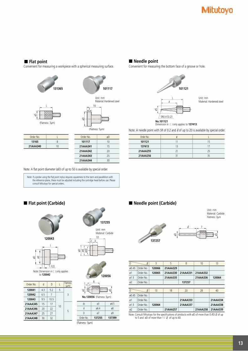
■ Ball point
■ Spherical point (Carbide)
■ Shell type point
■ Ball point
Provided with a large spherical point. This stylus is convenient for plane measurement.
Convenient for measuring an indentation.
* Please consult Mitutoyo for a request with a tip ball of ø0.5 to 10 specification.
Note: Please consult Mitutoyo for a request with a shell type point with øD of 1 or more (SR of 0.5 or more) specification.
Unit: mmMaterial: Carbide (only for tip of sphere)
Unit: mmMaterial: Hardened steel
L1.7
øD
SR
ød
Order No. øD ød SR L
120058 5.2 4.3 5 5
120059 7.5 6.5 7 10
120060 10.5 9.5 10 10
L
SR
øD ø5.2
7.3
SøD
ød
Unit: mm
101118
101122120059
13
d0 ø3 ø4.5
d ø6.4 ø8
D ø7 ø9
Order No. 137255 137399
(Flatness: 3µm)
Order No. L
101121 11 15
137413 13 17
21AAA255 21 25
21AAA256 31 35
Order No. L
13165 8
21AAA340 10
Order No. øD
101117 10
21AAA341 15
21AAA342 20
21AAA343 25
21AAA344 30
Order No. φd φD L Flatness(μm)
120041 4.3 5.2 5
3120042 6.5 7
10
120043 9.5 10.5
21AAA345 15 17
521AAA346 20 22
21AAA347 25 27
21AAA348 30 32
D ℓ 13 18 20 28 40
ø0.45 Order No.
ø1 Order No. 21AAA333 21AAA334
ø1.5 Order No. 120064 21AAA337 21AAA338
ø2 Order No. 21AAA257 21AAA258 21AAA339
Note: Consult Mitutoyo for the specifications of products with øD of more than 0.45/ℓof up to 5 and øD of more than 1 / ℓ of up to 40.
D ℓ 3 5 8 10 13
ø0.45 Order No. 120066 21AAA329
ø1 Order No. 120065 21AAA330 21AAA331 21AAA332
ø1.5 Order No. 21AAA335 21AAA336 120064
ø2 Order No. 137257
(Flatness: 3µm)
L
ø5
Unit: mmMaterial: Hardened steel
■ Flat point
■ Flat point (Carbide)
■ Needle point
■ Needle point (Carbide)
Convenient for measuring a workpiece with a spherical measuring surface. Convenient for measuring the bottom face of a groove or hole.
Note: A flat point diameter (øD) of up to 50 is available by special order.
Note: A needle point with SR of 0.2 and of up to 20 is available by special order. (Flatness: 5µm)
øD
310
Note: If a probe using the flat point stylus requires squareness to the stem and parallelism with the reference plane, these must be adjusted including the cartridge head before use. Please consult Mitutoyo for special orders.
8
ø2
L
ødøD
1.7(2)
1032
ødøD
No.120056 (Flatness: 3µm)
ød0
ø5
1
Note: Dimension in ( ) only applies to 120042
8
ø2
L
ødøD
1.7(2)
1032
ødøD
No.120056 (Flatness: 3µm)
ød0
ø5
1
Note: Dimension in ( ) only applies to 120042
8
ø2
L
ødøD
1.7(2)
1032
ødøD
No.120056 (Flatness: 3µm)
ød0
ø5
1
Note: Dimension in ( ) only applies to 120042
Unit: mmMaterial: Carbide
Unit: mmMaterial: CarbideFlatness: 3μm
L
SR0.4(0.2)
ø5
No.101121Dimension in ( ) only applies to 137413.
ℓ
7
øD ø5
ℓ
Unit: mmMaterial: Hardened steel
101117131365 101121
120043
137255
120056
137257
14
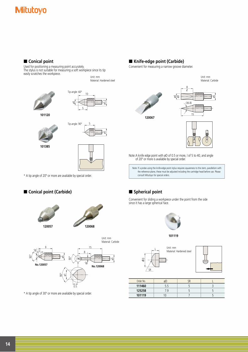
■ Conical point ■ Knife-edge point (Carbide)
■ Spherical point■ Conical point (Carbide)
Used for positioning a measuring point accurately.The stylus is not suitable for measuring a soft workpiece since its tipeasily scratches the workpiece.
Convenient for measuring a narrow groove diameter.
Convenient for sliding a workpiece under the point from the sidesince it has a large spherical face.
* A tip angle of 20° or more are available by special order.
* A tip angle of 30° or more are available by special order.
Note: A knife edge point with øD of 0.5 or more, l of 5 to 40, and angle of 20° or more is available by special order.
Note: If a probe using the knife-edge point stylus requires squareness to the stem, parallelism with the reference plane, these must be adjusted including the cartridge head before use. Please consult Mitutoyo for special orders.
Unit: mmMaterial: Carbide
5
Tip angle: 60°
Tip angle: 90°
No.101120
No.101385
ø5
10
5
ø5 ø5.2
5
Tip angle: 60°
Tip angle: 90°
No.101120
No.101385
ø5
10
5
ø5 ø5.2
5
Tip angle: 60°
Tip angle: 90°
No.101120
No.101385
ø510
5
ø5 ø5.2
Unit: mmMaterial: Hardened steel
9
90°
82
0.5
15
90°
90°
ø1
ø2No.120057 No.120068
ø2
ø5
ø515
ø4 øD
8
No.120067
ø5
ℓ
(36.8)
L
SR
φD
Unit: mmMaterial: Carbide
Unit: mmMaterial: Hardened steel
Order No. øD SR L111460 5.5 5 3125258 7.9 5 5101119 10 7 5
101120
101385
120067
120068120057
101119
15
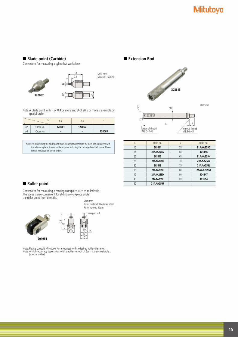
DL 0.4 0.6 1
ø2 Order No. 120061 120062 ー ø4 Order No. ー ー 120063
L Order No. L Order No.
10 303611 55 21AAA259G
15 21AAA259A 60 304146
20 303612 65 21AAA259H
25 21AAA259B 70 21AAA259J
30 303613 75 21AAA259L
35 21AAA259C 80 21AAA259M
40 21AAA259D 90 304147
45 21AAA259E 100 303614
50 21AAA259F
No.901954
R5
hexagon nut
2315
ø10
1093
L
external threadM2.5×0.45
5
ø5.2
ø5
internal threadM2.5×0.45
■ Blade point (Carbide)
■ Roller point
■ Extension RodConvenient for measuring a cylindrical workpiece.
Convenient for measuring a moving workpiece such as rolled strip.The stylus is also convenient for sliding a workpiece underthe roller point from the side.
Note: A blade point with H of 0.4 or more and D of ø0.5 or more is available by special order.
Note: Please consult Mitutoyo for a request with a desired roller diameter.Note: A high-accuracy type stylus with a roller runout of 5μm is also available. (special order)
Note: If a probe using the blade point stylus requires squareness to the stem and parallelism with the reference plane, these must be adjusted including the cartridge head before use. Please consult Mitutoyo for special orders.
Unit: mmRoller material: Hardened steelRoller runout: 10μm
Unit: mmMaterial: Carbide
Unit: mm
102.5
Hφ
D
φ5120062
303613
901954
16
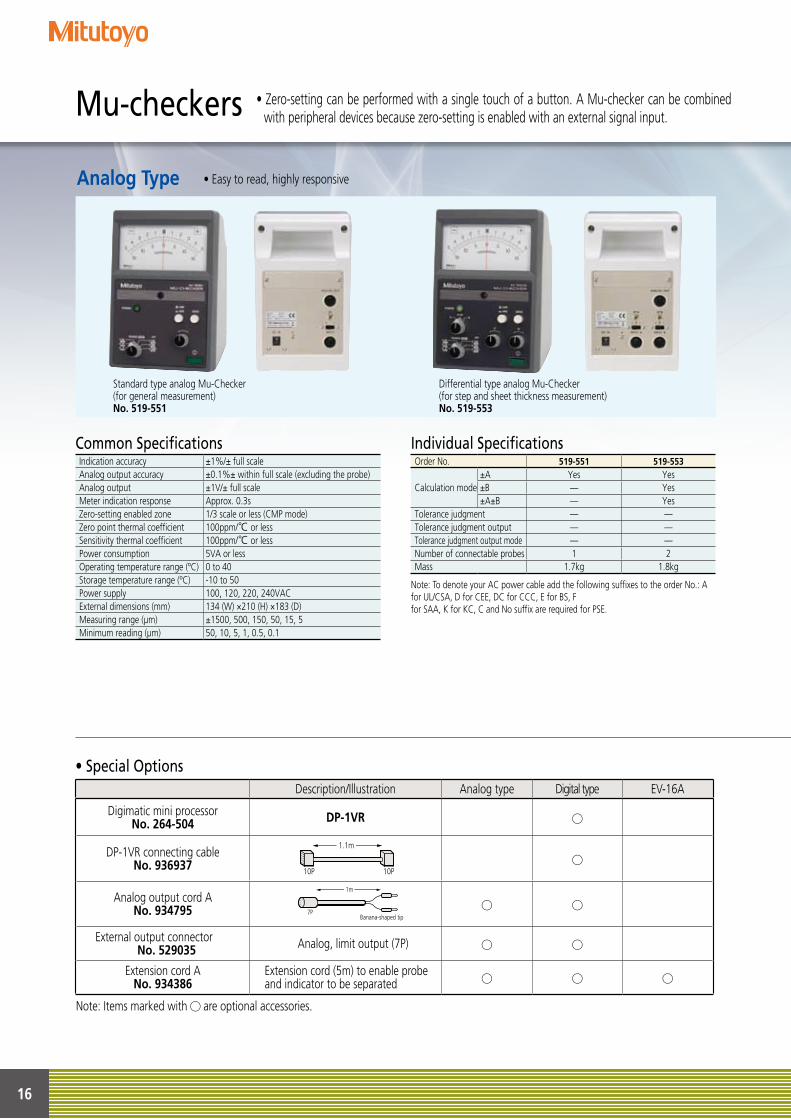
• Special Options
Mu-checkers • Zero-setting can be performed with a single touch of a button. A Mu-checker can be combined with peripheral devices because zero-setting is enabled with an external signal input.
Common SpecificationsIndication accuracy ±1%/± full scaleAnalog output accuracy ±0.1%± within full scale (excluding the probe)Analog output ±1V/± full scaleMeter indication response Approx. 0.3sZero-setting enabled zone 1/3 scale or less (CMP mode)Zero point thermal coefficient 100ppm/℃ or lessSensitivity thermal coefficient 100ppm/℃ or lessPower consumption 5VA or lessOperating temperature range (ºC) 0 to 40Storage temperature range (ºC) -10 to 50Power supply 100, 120, 220, 240VACExternal dimensions (mm) 134 (W) ×210 (H) ×183 (D)Measuring range (μm) ±1500, 500, 150, 50, 15, 5Minimum reading (μm) 50, 10, 5, 1, 0.5, 0.1
Individual SpecificationsOrder No. 519-551 519-553
±A Yes YesCalculation mode ±B — Yes
±A±B — YesTolerance judgment — —Tolerance judgment output — —Tolerance judgment output mode — —Number of connectable probes 1 2Mass 1.7kg 1.8kg
• Easy to read, highly responsiveAnalog Type
Standard type analog Mu-Checker(for general measurement)No. 519-551
Differential type analog Mu-Checker(for step and sheet thickness measurement)No. 519-553
Note: To denote your AC power cable add the following suffixes to the order No.: A for UL/CSA, D for CEE, DC for CCC, E for BS, Ffor SAA, K for KC, C and No suffix are required for PSE.
Description/Illustration Analog type Digital type EV-16A
Digimatic mini processorNo. 264-504 DP-1VR
DP-1VR connecting cableNo. 936937
1.1m
10P 10P
Analog output cord ANo. 934795
1m
7PBanana-shaped tip
External output connectorNo. 529035 Analog, limit output (7P)
Extension cord ANo. 934386
Extension cord (5m) to enable probe and indicator to be separated
Note: Items marked with are optional accessories.
17
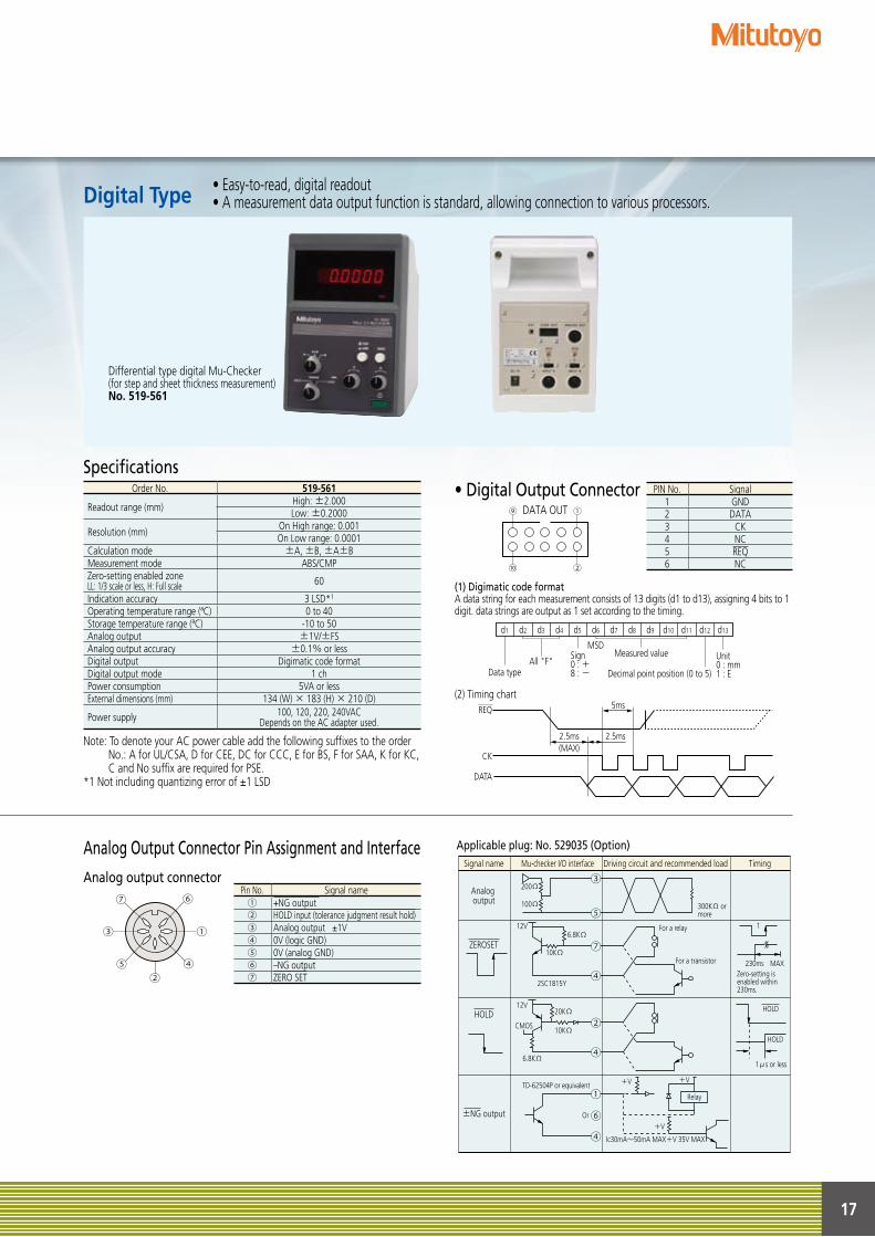
SpecificationsOrder No. 519-561
Readout range (mm) High: ±2.000Low: ±0.2000
Resolution (mm) On High range: 0.001On Low range: 0.0001
Calculation mode ±A, ±B, ±A±BMeasurement mode ABS/CMPZero-setting enabled zoneLL: 1/3 scale or less, H: Full scale 60
Indication accuracy 3 LSD*1
Operating temperature range (ªC) 0 to 40Storage temperature range (ªC) -10 to 50Analog output ±1V/±FSAnalog output accuracy ±0.1% or lessDigital output Digimatic code formatDigital output mode 1 chPower consumption 5VA or lessExternal dimensions (mm) 134 (W) × 183 (H) × 210 (D)
Power supply 100, 120, 220, 240VACDepends on the AC adapter used.
• Digital Output ConnectorDATA OUT
(1) Digimatic code formatA data string for each measurement consists of 13 digits (d1 to d13), assigning 4 bits to 1 digit. data strings are output as 1 set according to the timing.
(2) Timing chart
⑨ ①
⑩ ②
d13d12d11d10d9d8d7d6d5d4d3d2d1
Data typeAll "F"
Sign0 : +8 : -
MSDMeasured value
Decimal point position (0 to 5)
Unit0 : mm1 : E
REQ 5ms
2.5ms2.5ms(MAX)
CK
DATA
PIN No. Signal 1 GND2 DATA3 CK4 NC5 REQ6 NC
• Easy-to-read, digital readout• A measurement data output function is standard, allowing connection to various processors.Digital Type
Differential type digital Mu-Checker(for step and sheet thickness measurement)No. 519-561
Applicable plug: No. 529035 (Option)Analog Output Connector Pin Assignment and Interface
Analog output connector
⑤
③
②④
①
⑥⑦
Signal name
200Ω
100Ω
6.8KΩ
6.8KΩ
CMOS
TD-62504P or equivalent
Or
10KΩ
20KΩ
10KΩ
+V +V
+V
Ic30mA~50mA MAX+V 35V MAX
230ms
Relay
MAX
t
2SC1815Y
For a relay
For a transistor
Zero-setting is enabled within 230ms.
12V
12V
300KΩ or more
Analog output
±NG output
ZEROSET
HOLD
Mu-checker I/O interface Driving circuit and recommended load Timing
HOLD
HOLD
1μs or less
③
⑤
⑦
④
②
④
①
⑥
④
Pin No. Signal name① +NG output ② HOLD input (tolerance judgment result hold)③ Analog output ±1V④ 0V (logic GND)⑤ 0V (analog GND)⑥ –NG output⑦ ZERO SET
Note: To denote your AC power cable add the following suffixes to the order No.: A for UL/CSA, D for CEE, DC for CCC, E for BS, F for SAA, K for KC, C and No suffix are required for PSE.
*1 Not including quantizing error of ±1 LSD
18
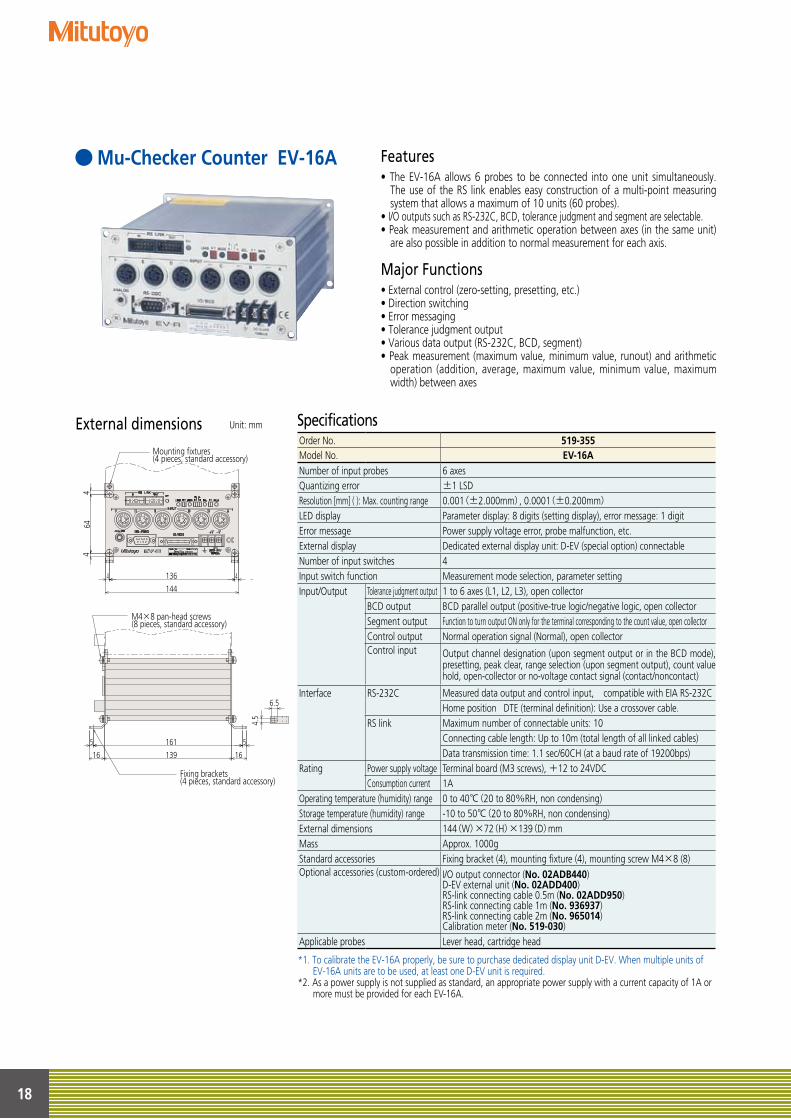
Mu-Checker Counter EV-16A Features• The EV-16A allows 6 probes to be connected into one unit simultaneously.
The use of the RS link enables easy construction of a multi-point measuring system that allows a maximum of 10 units (60 probes).
• I/O outputs such as RS-232C, BCD, tolerance judgment and segment are selectable.• Peak measurement and arithmetic operation between axes (in the same unit)
are also possible in addition to normal measurement for each axis.
Major Functions• External control (zero-setting, presetting, etc.) • Direction switching• Error messaging • Tolerance judgment output• Various data output (RS-232C, BCD, segment)• Peak measurement (maximum value, minimum value, runout) and arithmetic
operation (addition, average, maximum value, minimum value, maximum width) between axes
SpecificationsExternal dimensionsM4×8 pan-head screws (8 pieces, standard accessory)
Mounting fixtures (4 pieces, standard accessory)
4
64
4
144
136 4 4 5
16
5
16 139
161
6.5
4.5
Fixing brackets (4 pieces, standard accessory)M4×8 pan-head screws
(8 pieces, standard accessory)Mounting fixtures (4 pieces, standard accessory)
4
64
4
144
136 4 4 5
16
5
16 139
161
6.5
4.5
Fixing brackets (4 pieces, standard accessory)
*1. To calibrate the EV-16A properly, be sure to purchase dedicated display unit D-EV. When multiple units of EV-16A units are to be used, at least one D-EV unit is required.
*2. As a power supply is not supplied as standard, an appropriate power supply with a current capacity of 1A or more must be provided for each EV-16A.
Unit: mm
Order No. 519-355Model No. EV-16ANumber of input probes 6 axesQuantizing error ±1 LSDResolution [mm] ( ): Max. counting range 0.001(±2.000mm), 0.0001(±0.200mm)LED display Parameter display: 8 digits (setting display), error message: 1 digitError message Power supply voltage error, probe malfunction, etc.External display Dedicated external display unit: D-EV (special option) connectableNumber of input switches 4Input switch function Measurement mode selection, parameter settingInput/Output Tolerance judgment output 1 to 6 axes (L1, L2, L3), open collector
BCD output BCD parallel output (positive-true logic/negative logic, open collectorSegment output Function to turn output ON only for the terminal corresponding to the count value, open collectorControl output Normal operation signal (Normal), open collectorControl input Output channel designation (upon segment output or in the BCD mode),
presetting, peak clear, range selection (upon segment output), count value hold, open-collector or no-voltage contact signal (contact/noncontact)
Interface RS-232C Measured data output and control input, compatible with EIA RS-232CHome position DTE (terminal definition): Use a crossover cable.
RS link Maximum number of connectable units: 10Connecting cable length: Up to 10m (total length of all linked cables) Data transmission time: 1.1 sec/60CH (at a baud rate of 19200bps)
Rating Power supply voltage Terminal board (M3 screws), +12 to 24VDCConsumption current 1A
Operating temperature (humidity) range 0 to 40℃(20 to 80%RH, non condensing)Storage temperature (humidity) range -10 to 50℃(20 to 80%RH, non condensing)External dimensions 144(W)×72(H)×139(D)mmMass Approx. 1000gStandard accessories Fixing bracket (4), mounting fixture (4), mounting screw M4×8 (8)Optional accessories (custom-ordered) I/O output connector (No. 02ADB440)
D-EV external unit (No. 02ADD400) RS-link connecting cable 0.5m (No. 02ADD950) RS-link connecting cable 1m (No. 936937) RS-link connecting cable 2m (No. 965014) Calibration meter (No. 519-030)
Applicable probes Lever head, cartridge head
19
Terminal board connecting cableNo. 02ADD930
External dimensions
-V+V
-V+V
96 6.6 67 (11) 91.4
44.448
000001EV-I02ADD400
MADE IN JAPANSerial No.ModelCode No.
200mADC12-24V
OUT
INRS LIN
K
MODE P.SETFnDISP
GAGE
MAX MINTIR
UNIT +NG
GO
-NG
000001EV-I02ADD400
MADE IN JAPAN
Serial No.ModelCode No.
200mADC12-24V
OUTIN RS LINK
-V+V
-V+V
96 6.6 67 (11) 91.4
44.448
000001EV-I02ADD400
Serial No.ModelCode No.
200mADC12-24V
OUT
INRS LIN
K
MODE P.SETFnDISP
GAGE
MAX MINTIR
UNIT +NG
GO
-NG
000001EV-I02ADD400
MADE IN JAPAN
Serial No.ModelCode No.
200mADC12-24V
OUTIN RS LINK
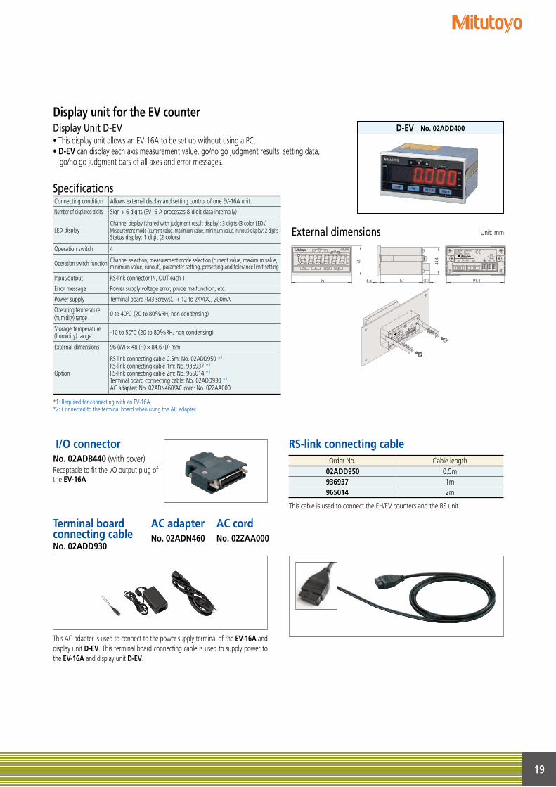
I/O connectorNo. 02ADB440 (with cover) Receptacle to fit the I/O output plug of the EV-16A
Unit: mm
• This display unit allows an EV-16A to be set up without using a PC.• D-EV can display each axis measurement value, go/no go judgment results, setting data,
go/no go judgment bars of all axes and error messages.
Specifications
*1: Required for connecting with an EV-16A. *2: Connected to the terminal board when using the AC adapter.
Display unit for the EV counter Display Unit D-EV D-EV No. 02ADD400
Connecting condition Allows external display and setting control of one EV-16A unit.
Number of displayed digits Sign + 6 digits (EV16-A processes 8-digit data internally)
LED displayChannel display (shared with judgment result display): 3 digits (3 color LEDs) Measurement mode (current value, maximum value, minimum value, runout) display: 2 digits Status display: 1 digit (2 colors)
Operation switch 4
Operation switch function Channel selection, measurement mode selection (current value, maximum value, minimum value, runout), parameter setting, presetting and tolerance limit setting
Input/output RS-link connector IN, OUT each 1
Error message Power supply voltage error, probe malfunction, etc.
Power supply Terminal board (M3 screws), + 12 to 24VDC, 200mA
Operating temperature (humidity) range 0 to 40ºC (20 to 80%RH, non condensing)
Storage temperature (humidity) range -10 to 50ºC (20 to 80%RH, non condensing)
External dimensions 96 (W) × 48 (H) × 84.6 (D) mm
Option
RS-link connecting cable 0.5m: No. 02ADD950 *1
RS-link connecting cable 1m: No. 936937 *1
RS-link connecting cable 2m: No. 965014 *1 Terminal board connecting cable: No. 02ADD930 *2 AC adapter: No. 02ADN460/AC cord: No. 02ZAA000
This AC adapter is used to connect to the power supply terminal of the EV-16A and display unit D-EV. This terminal board connecting cable is used to supply power to the EV-16A and display unit D-EV.
RS-link connecting cable
This cable is used to connect the EH/EV counters and the RS unit.
Order No. Cable length02ADD950 0.5m936937 1m965014 2m
AC adapterNo. 02ADN460
AC cordNo. 02ZAA000
20
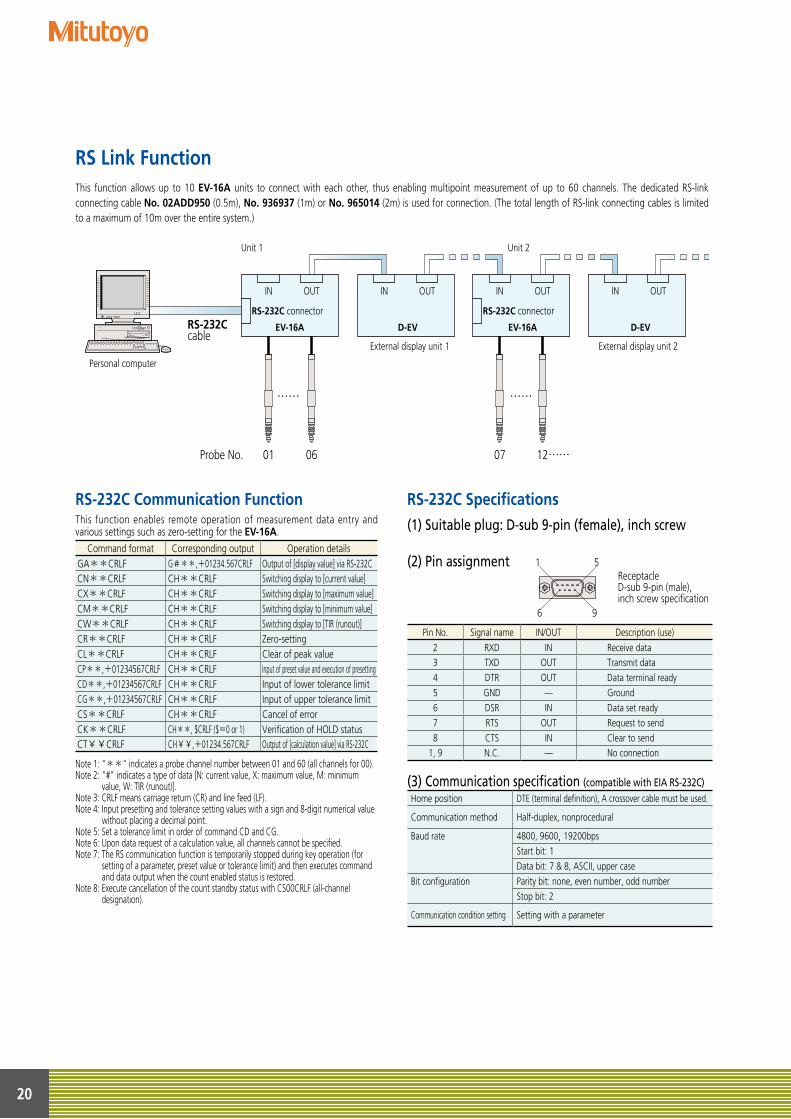
RS Link FunctionThis function allows up to 10 EV-16A units to connect with each other, thus enabling multipoint measurement of up to 60 channels. The dedicated RS-link connecting cable No. 02ADD950 (0.5m), No. 936937 (1m) or No. 965014 (2m) is used for connection. (The total length of RS-link connecting cables is limited to a maximum of 10m over the entire system.)
Personal computer
IN
RS-232C connector
Unit 1 Unit 2
RS-232Ccable
01Probe No. 06 07 12……
…… ……
OUT IN OUT IN
RS-232C connector
OUT
External display unit 1 External display unit 2
IN OUT
EV-16A D-EV EV-16A D-EV
RS-232C Specifications(1) Suitable plug: D-sub 9-pin (female), inch screw
(2) Pin assignment
(3) Communication specification (compatible with EIA RS-232C)
1 5
6 9
Receptacle D-sub 9-pin (male), inch screw specification
RS-232C Communication FunctionThis function enables remote operation of measurement data entry and various settings such as zero-setting for the EV-16A.
Note 1: "**" indicates a probe channel number between 01 and 60 (all channels for 00).Note 2: "#" indicates a type of data [N: current value, X: maximum value, M: minimum
value, W: TIR (runout)].Note 3: CRLF means carriage return (CR) and line feed (LF).Note 4: Input presetting and tolerance setting values with a sign and 8-digit numerical value
without placing a decimal point.Note 5: Set a tolerance limit in order of command CD and CG.Note 6: Upon data request of a calculation value, all channels cannot be specified.Note 7: The RS communication function is temporarily stopped during key operation (for
setting of a parameter, preset value or tolerance limit) and then executes command and data output when the count enabled status is restored.
Note 8: Execute cancellation of the count standby status with CS00CRLF (all-channel designation).
Command format Corresponding output Operation details GA**CRLF G#**,+01234.567CRLF Output of [display value] via RS-232C CN**CRLF CH**CRLF Switching display to [current value] CX**CRLF CH**CRLF Switching display to [maximum value] CM**CRLF CH**CRLF Switching display to [minimum value]CW**CRLF CH**CRLF Switching display to [TIR (runout)]CR**CRLF CH**CRLF Zero-settingCL**CRLF CH**CRLF Clear of peak valueCP**,+01234567CRLF CH**CRLF Input of preset value and execution of presettingCD**,+01234567CRLF CH**CRLF Input of lower tolerance limitCG**,+01234567CRLF CH**CRLF Input of upper tolerance limitCS**CRLF CH**CRLF Cancel of errorCK**CRLF CH**, $CRLF ($=0 or 1) Verification of HOLD statusCT¥¥CRLF CH¥¥,+01234.567CRLF Output of [calculation value] via RS-232C
Pin No. Signal name IN/OUT Description (use)
2 RXD IN Receive data 3 TXD OUT Transmit data 4 DTR OUT Data terminal ready 5 GND — Ground 6 DSR IN Data set ready 7 RTS OUT Request to send 8 CTS IN Clear to send
1, 9 N.C. — No connection
Home position DTE (terminal definition), A crossover cable must be used.
Communication method Half-duplex, nonprocedural
Baud rate 4800, 9600, 19200bpsStart bit: 1Data bit: 7 & 8, ASCII, upper case
Bit configuration Parity bit: none, even number, odd numberStop bit: 2
Communication condition setting Setting with a parameter
21
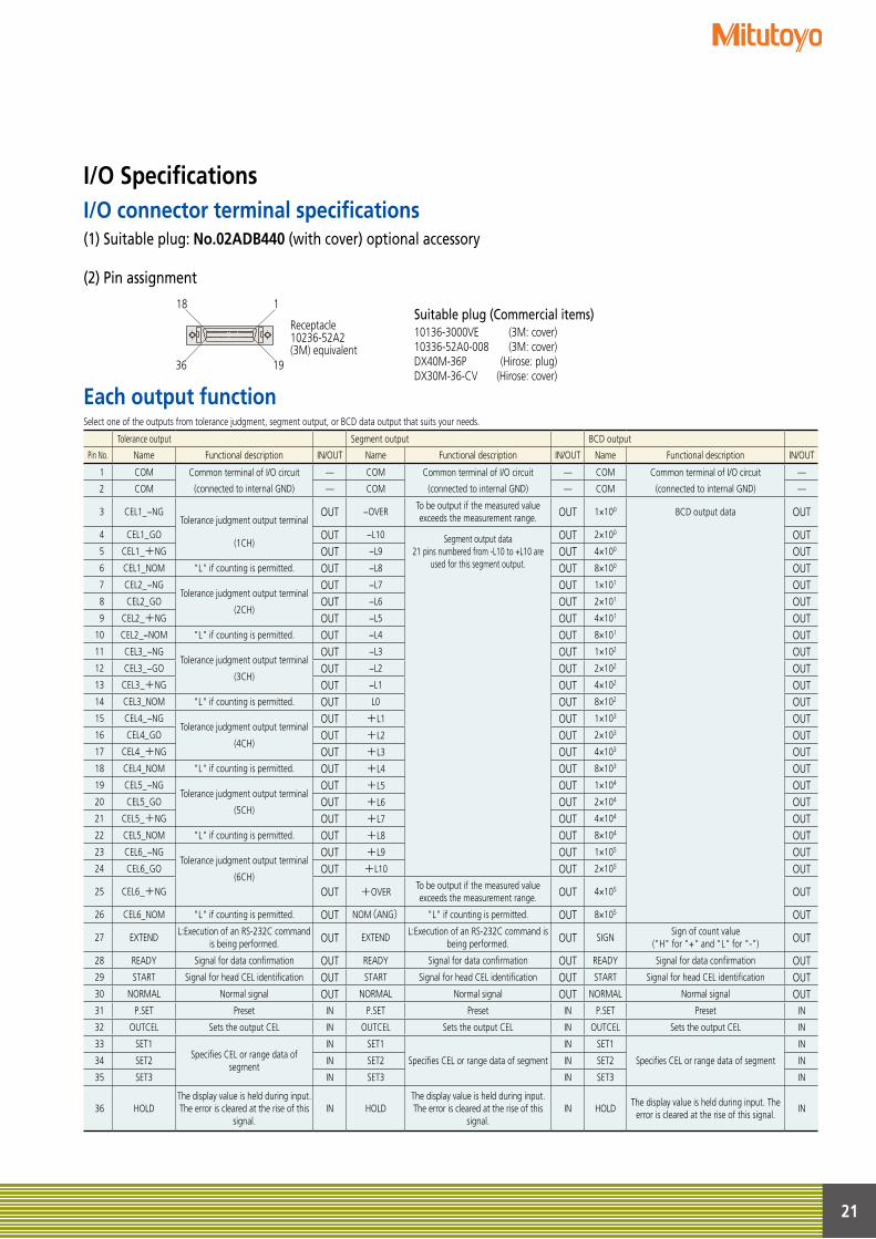
I/O SpecificationsI/O connector terminal specifications
Each output function
(1) Suitable plug: No.02ADB440 (with cover) optional accessory
(2) Pin assignment
Suitable plug (Commercial items)10136-3000VE (3M: cover)10336-52A0-008 (3M: cover)DX40M-36P (Hirose: plug)DX30M-36-CV (Hirose: cover)
18 1
36 19
Receptacle10236-52A2(3M) equivalent
Select one of the outputs from tolerance judgment, segment output, or BCD data output that suits your needs.
Tolerance output Segment output BCD output
Pin No. Name Functional description IN/OUT Name Functional description IN/OUT Name Functional description IN/OUT
1 COM Common terminal of I/O circuit — COM Common terminal of I/O circuit — COM Common terminal of I/O circuit —
2 COM (connected to internal GND) — COM (connected to internal GND) — COM (connected to internal GND) —
3 CEL1 −NGTolerance judgment output terminal
OUT −OVERTo be output if the measured valueexceeds the measurement range. OUT 1×100 BCD output data OUT
4 CEL1 GO(1CH)
OUT −L10 Segment output data21 pins numbered from -L10 to +L10 are
used for this segment output.
OUT 2×100 OUT5 CEL1 +NG OUT −L9 OUT 4×100 OUT6 CEL1 NOM "L" if counting is permitted. OUT −L8 OUT 8×100 OUT7 CEL2 −NG
Tolerance judgment output terminalOUT −L7 OUT 1×101 OUT
8 CEL2 GO(2CH)
OUT −L6 OUT 2×101 OUT9 CEL2 +NG OUT −L5 OUT 4×101 OUT
10 CEL2 −NOM "L" if counting is permitted. OUT −L4 OUT 8×101 OUT11 CEL3 −NG
Tolerance judgment output terminalOUT −L3 OUT 1×10² OUT
12 CEL3 −GO(3CH)
OUT −L2 OUT 2×10² OUT13 CEL3 +NG OUT −L1 OUT 4×10² OUT14 CEL3 NOM "L" if counting is permitted. OUT L0 OUT 8×10² OUT15 CEL4 −NG
Tolerance judgment output terminalOUT +L1 OUT 1×10³ OUT
16 CEL4 GO(4CH)
OUT +L2 OUT 2×10³ OUT17 CEL4 +NG OUT +L3 OUT 4×10³ OUT18 CEL4 NOM "L" if counting is permitted. OUT +L4 OUT 8×10³ OUT19 CEL5 −NG
Tolerance judgment output terminalOUT +L5 OUT 1×10⁴ OUT
20 CEL5 GO(5CH)
OUT +L6 OUT 2×10⁴ OUT21 CEL5 +NG OUT +L7 OUT 4×10⁴ OUT22 CEL5 NOM "L" if counting is permitted. OUT +L8 OUT 8×10⁴ OUT23 CEL6 −NG
Tolerance judgment output terminalOUT +L9 OUT 1×10⁵ OUT
24 CEL6 GO(6CH)
OUT +L10 OUT 2×10⁵ OUT
25 CEL6 +NG OUT +OVERTo be output if the measured valueexceeds the measurement range. OUT 4×10⁵ OUT
26 CEL6 NOM "L" if counting is permitted. OUT NOM(ANG) "L" if counting is permitted. OUT 8×10⁵ OUT
27 EXTENDL:Execution of an RS-232C command
is being performed. OUT EXTENDL:Execution of an RS-232C command is
being performed. OUT SIGNSign of count value
("H" for "+" and "L" for "-") OUT
28 READY Signal for data confirmation OUT READY Signal for data confirmation OUT READY Signal for data confirmation OUT29 START Signal for head CEL identification OUT START Signal for head CEL identification OUT START Signal for head CEL identification OUT30 NORMAL Normal signal OUT NORMAL Normal signal OUT NORMAL Normal signal OUT31 P.SET Preset IN P.SET Preset IN P.SET Preset IN
32 OUTCEL Sets the output CEL IN OUTCEL Sets the output CEL IN OUTCEL Sets the output CEL IN
33 SET1Specifies CEL or range data of
segment
IN SET1
Specifies CEL or range data of segment
IN SET1
Specifies CEL or range data of segment
IN
34 SET2 IN SET2 IN SET2 IN
35 SET3 IN SET3 IN SET3 IN
36 HOLDThe display value is held during input. The error is cleared at the rise of this
signal. IN HOLD
The display value is held during input. The error is cleared at the rise of this
signal. IN HOLD
The display value is held during input. The error is cleared at the rise of this signal.
IN
22
Powersupply Min 2sec
Max 2sec
Min 35ms
Max 35ms
HOLD
NORMAL
I/O output
Min 70ms
CEL1 CEL2 CEL3 CEL4 CEL5 CEL6
Min 15ms
HOLD
START
READY
READY
Max 40ms1.6ms・2ms
5ms・6ms
Tolerance judgment, segment, BCD data
Tolerance judgment, segment, BCD data
Data latch 2.5ms (40ms at smoothing ON)
30ms・35ms
CEL1 CEL2 CEL3 CEL4 CEL5 CEL6
START
READY
1.6ms・2ms5ms・6ms
Tolerance judgment, segment, BCD data
READY
12ms・15ms(1.6ms・2ms)
30ms・35ms(5ms)
Tolerance judgment, segment, BCD data
Min 70ms
Max 40ms(Max 15ms)[Max 80ms]
12ms・15ms(1.6ms・2ms)
( ): Time upon output in high-speed mode[ ]: Time upon output in calculation mode
Min 15ms
HOLD
Data latch 2.5ms (40ms at smoothing ON)
( ): Time upon output in high-speed mode
Max 35ms(Max 10ms)[Max 90ms]
Max 35ms(Max 10ms)[Max 90ms]
( ): Time upon output in high-speed mode However, only for the specified CEL (excluding All-CEL)[ ]: Time upon output in calculation mode
P.SET
DATA
SET 1, 2, 3
Min 10ms Min 10ms
Max 40ms
Min 15ms
-NG
Upper tolerance limit
Lower tolerance limit
+NG
OUTSEL
DATA
SET 1, 2, 3
Min 10ms Min 10ms
Max 40ms
Min 15ms
P.SET
HOLD
DATA
SET 1, 2, 3
Min 15ms
Max 40ms
Min 10msMin 10ms
Powersupply Min 2sec
Max 2sec
Min 35ms
Max 35ms
HOLD
NORMAL
I/O output
Min 70ms
CEL1 CEL2 CEL3 CEL4 CEL5 CEL6
Min 15ms
HOLD
START
READY
READY
Max 40ms1.6ms・2ms
5ms・6ms
Tolerance judgment, segment, BCD data
Tolerance judgment, segment, BCD data
Data latch 2.5ms (40ms at smoothing ON)
30ms・35ms
CEL1 CEL2 CEL3 CEL4 CEL5 CEL6
START
READY
1.6ms・2ms5ms・6ms
Tolerance judgment, segment, BCD data
READY
12ms・15ms(1.6ms・2ms)
30ms・35ms(5ms)
Tolerance judgment, segment, BCD data
Min 70ms
Max 40ms(Max 15ms)[Max 80ms]
12ms・15ms(1.6ms・2ms)
( ): Time upon output in high-speed mode[ ]: Time upon output in calculation mode
Min 15ms
HOLD
Data latch 2.5ms (40ms at smoothing ON)
( ): Time upon output in high-speed mode
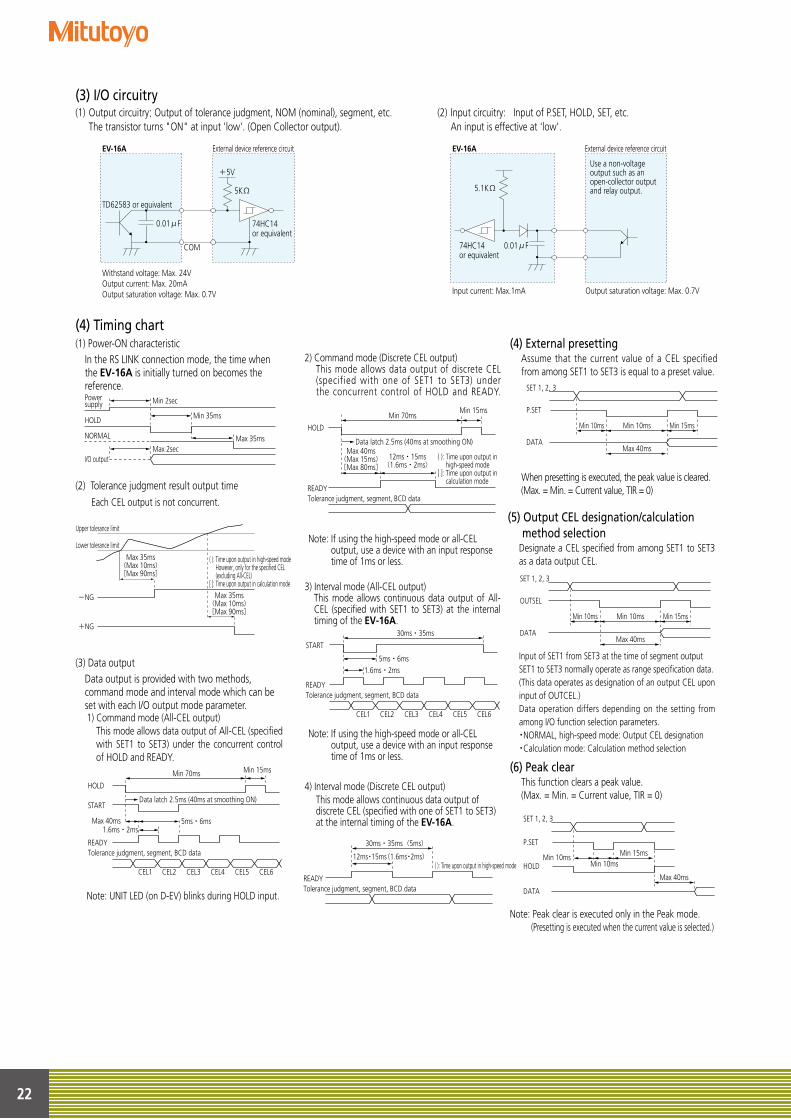
(3) I/O circuitry
(4) Timing chart
(1) Output circuitry: Output of tolerance judgment, NOM (nominal), segment, etc. The transistor turns "ON" at input 'low'. (Open Collector output).
(2) Input circuitry: Input of P.SET, HOLD, SET, etc. An input is effective at 'low'.
+5V
5KΩ
COM
74HC14 or equivalent
0.01μF
TD62583 or equivalent
Withstand voltage: Max. 24VOutput current: Max. 20mAOutput saturation voltage: Max. 0.7V
EV-16A External device reference circuit
Input current: Max.1mA Output saturation voltage: Max. 0.7V
EV-16A External device reference circuit
Use a non-voltage output such as an open-collector output and relay output.5.1KΩ
0.01μF74HC14 or equivalent
(1) Power-ON characteristic In the RS LINK connection mode, the time when
the EV-16A is initially turned on becomes the reference.
(2) Tolerance judgment result output time Each CEL output is not concurrent.
(3) Data output Data output is provided with two methods,
command mode and interval mode which can be set with each I/O output mode parameter. 1) Command mode (All-CEL output)
This mode allows data output of All-CEL (specified with SET1 to SET3) under the concurrent control of HOLD and READY.
Note: UNIT LED (on D-EV) blinks during HOLD input.
(4) External presetting Assume that the current value of a CEL specified from among SET1 to SET3 is equal to a preset value.
When presetting is executed, the peak value is cleared.(Max. = Min. = Current value, TIR = 0)
(5) Output CEL designation/calculation method selection
Designate a CEL specified from among SET1 to SET3 as a data output CEL.
Input of SET1 from SET3 at the time of segment outputSET1 to SET3 normally operate as range specification data.(This data operates as designation of an output CEL upon input of OUTCEL.) Data operation differs depending on the setting from among I/O function selection parameters.・NORMAL, high-speed mode: Output CEL designation・Calculation mode: Calculation method selection
Max 35ms(Max 10ms)[Max 90ms]
Max 35ms(Max 10ms)[Max 90ms]
( ): Time upon output in high-speed mode However, only for the specified CEL (excluding All-CEL)[ ]: Time upon output in calculation mode
P.SET
DATA
SET 1, 2, 3
Min 10ms Min 10ms
Max 40ms
Min 15ms
-NG
Upper tolerance limit
Lower tolerance limit
+NG
OUTSEL
DATA
SET 1, 2, 3
Min 10ms Min 10ms
Max 40ms
Min 15ms
P.SET
HOLD
DATA
SET 1, 2, 3
Min 15ms
Max 40ms
Min 10msMin 10ms
(6) Peak clearThis function clears a peak value.(Max. = Min. = Current value, TIR = 0)
Note: Peak clear is executed only in the Peak mode. (Presetting is executed when the current value is selected.)
4) Interval mode (Discrete CEL output) This mode allows continuous data output of discrete CEL (specified with one of SET1 to SET3) at the internal timing of the EV-16A.
3) Interval mode (All-CEL output) This mode allows continuous data output of All-CEL (specified with SET1 to SET3) at the internal timing of the EV-16A.
Note: If using the high-speed mode or all-CEL output, use a device with an input response time of 1ms or less.
2) Command mode (Discrete CEL output) This mode allows data output of discrete CEL (specified with one of SET1 to SET3) under the concurrent control of HOLD and READY.
Note: If using the high-speed mode or all-CEL output, use a device with an input response time of 1ms or less.
Powersupply Min 2sec
Max 2sec
Min 35ms
Max 35ms
HOLD
NORMAL
I/O output
Min 70ms
CEL1 CEL2 CEL3 CEL4 CEL5 CEL6
Min 15ms
HOLD
START
READY
READY
Max 40ms1.6ms・2ms
5ms・6ms
Tolerance judgment, segment, BCD data
Tolerance judgment, segment, BCD data
Data latch 2.5ms (40ms at smoothing ON)
30ms・35ms
CEL1 CEL2 CEL3 CEL4 CEL5 CEL6
START
READY
1.6ms・2ms5ms・6ms
Tolerance judgment, segment, BCD data
READY
12ms・15ms(1.6ms・2ms)
30ms・35ms(5ms)
Tolerance judgment, segment, BCD data
Min 70ms
Max 40ms(Max 15ms)[Max 80ms]
12ms・15ms(1.6ms・2ms)
( ): Time upon output in high-speed mode[ ]: Time upon output in calculation mode
Min 15ms
HOLD
Data latch 2.5ms (40ms at smoothing ON)
( ): Time upon output in high-speed mode
Max 35ms(Max 10ms)[Max 90ms]
Max 35ms(Max 10ms)[Max 90ms]
( ): Time upon output in high-speed mode However, only for the specified CEL (excluding All-CEL)[ ]: Time upon output in calculation mode
P.SET
DATA
SET 1, 2, 3
Min 10ms Min 10ms
Max 40ms
Min 15ms
-NG
Upper tolerance limit
Lower tolerance limit
+NG
OUTSEL
DATA
SET 1, 2, 3
Min 10ms Min 10ms
Max 40ms
Min 15ms
P.SET
HOLD
DATA
SET 1, 2, 3
Min 15ms
Max 40ms
Min 10msMin 10ms
Max 35ms(Max 10ms)[Max 90ms]
Max 35ms(Max 10ms)[Max 90ms]
( ): Time upon output in high-speed mode However, only for the specified CEL (excluding All-CEL)[ ]: Time upon output in calculation mode
P.SET
DATA
SET 1, 2, 3
Min 10ms Min 10ms
Max 40ms
Min 15ms
-NG
Upper tolerance limit
Lower tolerance limit
+NG
OUTSEL
DATA
SET 1, 2, 3
Min 10ms Min 10ms
Max 40ms
Min 15ms
P.SET
HOLD
DATA
SET 1, 2, 3
Min 15ms
Max 40ms
Min 10msMin 10ms
23
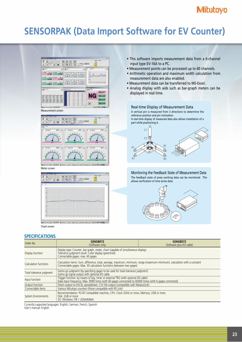
SENSORPAK (Data Import Software for EV Counter)
Real-time Display of Measurement DataA vertical pin is measured from 3 directions to determine the reference position and pin inclination.A real-time display of measured data also allows installation of a part while positioning it.
A1
C1
C2
A1
B1
B2
• This software imports measurement data from a 6-channel input type EV-16A to a PC.
• Measurement points can be processed up to 60 channels.• Arithmetic operation and maximum width calculation from
measurement data are also enabled.• Measurement data can be transferred to MS-Excel.• Analog display with aids such as bar-graph meters can be
displayed in real time.
Measurement screen
Meter screen
Chart screen
Monitoring the Feedback State of Measurement DataThe feedback state of press working data can be monitored. This allows verification of time series data.
SPECIFICATIONSOrder No. 02NGB072
(Software only)02NGB073
(Software plus I/O cable)
Display functionDisplay type: Counter, bar graph, meter, chart (capable of simultaneous display)Tolerance judgment result: Color display (green/red)Connectable gages: max. 60 gages
Calculation functions Calculation items: Sum, difference, total, average, maximum, minimum, range (maximum–minimum), calculation with a constantConnectable gages: Max. 30 calculation functions (between two gages)
Total tolerance judgment Go/no go judgment (by specifying gages to be used for total tolerance judgment)Go/no go signal output with optional I/O cable
Input function Trigger function: by means of key, timer or external TRG (with optional I/O cable)Data input frequency: Max. 9999 times (with 60 gages connected) to 60000 times (with 6 gages connected)
Output function Direct output to EXCEL spreadsheet, CSV file output (compatible with MeasurLink)Connectable items Various Mitutoyo counters (those compatible with RS Link)
System EnvironmentsRecommendation: PC/AT compatible machine, CPU: Clock 2GHz or more, Memory: 2GB or moreDisk: 2GB or moreOS: Windows 7/8.1 (32bit/64bit)
Currently supported languages: English, German, French, SpanishUser’s manual: English
128
1602
(2) A
-(CH)
NE, P
rinte
d in
Japa
n
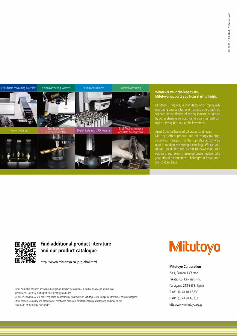
Coordinate Measuring Machines
Sensor Systems
Vision Measuring Systems
Test Equipmentand Seismometers
Form Measurement
Digital Scale and DRO Systems
Optical Measuring
Small Tool Instrumentsand Data Management
http://www.mitutoyo.co.jp/global.html
Find additional product literature and our product catalogue
Note: Product illustrations are without obligation. Product descriptions, in particular any and all technical specifications, are only binding when explicitly agreed upon.MITUTOYO and MiCAT are either registered trademarks or trademarks of Mitutoyo Corp. in Japan and/or other countries/regions. Other product, company and brand names mentioned herein are for identification purposes only and may be the trademarks of their respective holders.
Mitutoyo Corporation
20-1, Sakado 1-Chome,
Takatsu-ku, Kawasaki-shi,
Kanagawa 213-8533, Japan
T +81 (0) 44 813-8230
F +81 (0) 44 813-8231
http://www.mitutoyo.co.jp
Whatever your challenges are, Mitutoyo supports you from start to finish.
Mitutoyo is not only a manufacturer of top quality measuring products but one that also offers qualified support for the lifetime of the equipment, backed up by comprehensive services that ensure your staff can make the very best use of the investment.
Apart from the basics of calibration and repair, Mitutoyo offers product and metrology training, as well as IT support for the sophisticated software used in modern measuring technology. We can also design, build, test and deliver bespoke measuring solutions and even, if deemed cost-effective, take your critical measurement challenges in-house on a sub-contract basis.