electronic battleship
TRANSCRIPT
Electronic Battleship
Michelle Meyer
1 Abstract
This project is an Arduino-based recreation of the game battleship—and it is cheat-proof! In this game, the ships’ positions are detected after being placed on the board. In addition, the hits and misses are displayed using LEDs which light up either red or blue. The main challenge of the project is getting the large number of inputs and outputs to be detected and controlled by a limited number of Arduino pins: the five ships can be placed on any of the 20 rows and columns and there are 400 LEDs. This is done using multiplexing for the ship detection system, and the LEDs are placed in a matrix and controlled using a decade counter. The duration of one cycle through lighting the LED matrix was measured to be 6.96ms, and each LED is on for 3.97% of the time.
2 Introduction
2.1 Inspiration
With the expansion of computer, tablet and phone technology, more and more games are being digitalized. The crispness of these games is nice, but there is also something enjoyable about playing a physical game. This project is a combination of both: it is a higher tech version of the classic game of Battleship. The game has the same rules as the classic game, and the players still have the fun of placing their ships on the grid. This version of the game allows the players to punch in their guesses in a keypad and the guess lights up on the board for them. This new method makes the game cheat-proof while still being engaging and strategic. This game is a representation of how new technology and electronics techniques can bring improvements to our lives. As the
This paper was written for Dr. James Dann’s Applied Science Research class in the spring of 2016.
116 Michelle Meyer
world of electronics continues to grow, there will only be more possible applications. Though electronic Battleship isn’t going to change the world, it still an entertaining application of electrical and technological advances made in the last few decades, namely microprocessors, multiplexing, and LEDs.
I first got the idea for this project when I discovered RGB LEDs. Before then, I had seen many online tutorials for LED matrices but none of them utilized RGB LEDs. In order to create these LED matrices with standard one-color LEDs, the LEDs’ pins are bent and connected to each other so that the cathodes connect in a row and the anodes connect in a column (or vice versa). I had the idea for an RGB LED matrix, which would use the same concept as the standard LED matrix except there would be additional rows for each of the different colored pins. After thinking of the idea of an RGB matrix, I was brainstorming applications for the matrix beyond displaying cool patterns when battleship came to mind.
There was an electronic version of Battleship that was sold before, and the goal of this project is to make an improved version. The version that was sold required the player to search through a book of ship positions and enter in the code manually. This version detects the ships’ positions automatically, which saves the players’ time and ensures that no cheating is possible. Additionally, this version has lights that display the hits and misses instead of the traditional red and white pegs.
2.2 History
LEDs were first invented in 1961 on a project related to solar cells. It was discovered that semiconductors could be used to produce light. The red LED was then patented in 1962. In later years, different colored LEDs were produced but it wasn’t until 1979 that LEDs were available for a reasonably low cost [1]. Initially, LEDs were extremely inefficient but changes to the composition of the active layer greatly improved the efficiency in the 1990s. The most significant discovery was that having a heterogeneous composition of the n and p type layers increases the efficiency [2]. This increases efficiency because the different materials
THE MENLO ROUNDTABLE 117
have slightly different structures, so overall the probability that an electron can find a hole and vice versa is higher. This, along with increased quality of the materials that compose the layers, increased LED efficiency dramatically from when they were first invented, and the efficiency continues to rise. Today, LEDs are used for a variety of applications including display. LEDs can be combined to create images for things like billboards. On a smaller scale, LED matrices have been a popular thing for hobbyists to experiment with. These matrices can be controlled by Arduinos to display a certain pattern. 3D displays have even become popular, adding a challenging spacial element to the project. However, for this project, the focus is 2D matrices. This project takes the LED matrix to the next level by not only allowing the user to control which LEDs light up, but also adding the strategic game element.
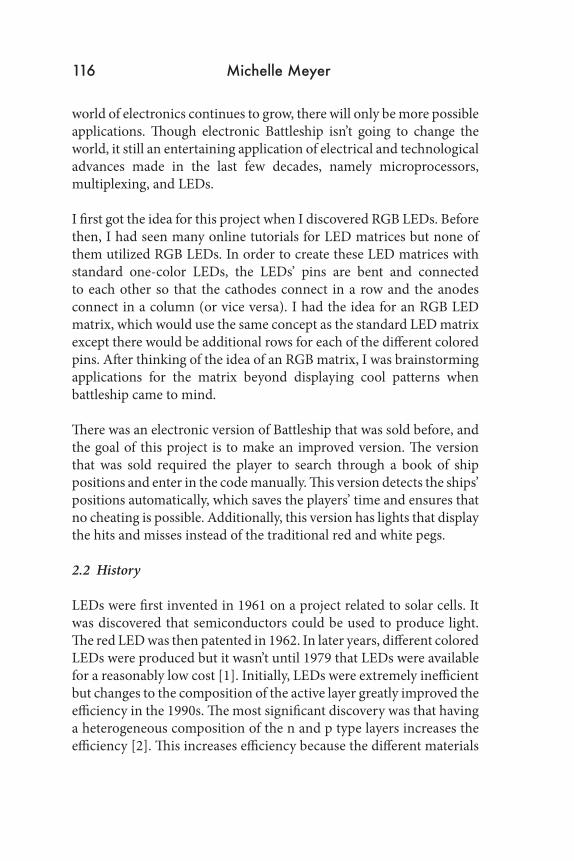
Multiplexing is the process of combining and splitting data up to make the transfer more efficient. Data is picked up from multiple sources, and combined into one large piece of data. An example of this is shown below.
Figure 1: This diagram outlines the process of multiplexing. [3]
However, each source of data is unique in some way that allows it to be distinguishable even after combined. This could be done in
118 Michelle Meyer
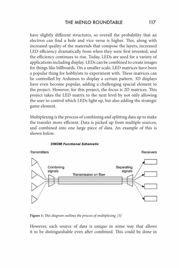
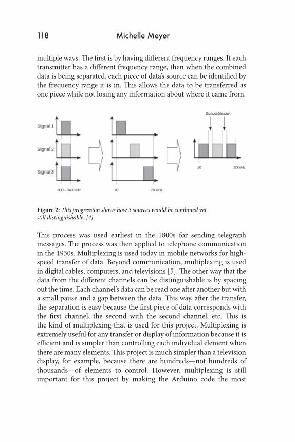
multiple ways. The first is by having different frequency ranges. If each transmitter has a different frequency range, then when the combined data is being separated, each piece of data’s source can be identified by the frequency range it is in. This allows the data to be transferred as one piece while not losing any information about where it came from.
Figure 2: This progression shows how 3 sources would be combined yet still distinguishable. [4]
This process was used earliest in the 1800s for sending telegraph messages. The process was then applied to telephone communication in the 1930s. Multiplexing is used today in mobile networks for high-speed transfer of data. Beyond communication, multiplexing is used in digital cables, computers, and televisions [5]. The other way that the data from the different channels can be distinguishable is by spacing out the time. Each channel’s data can be read one after another but with a small pause and a gap between the data. This way, after the transfer, the separation is easy because the first piece of data corresponds with the first channel, the second with the second channel, etc. This is the kind of multiplexing that is used for this project. Multiplexing is extremely useful for any transfer or display of information because it is efficient and is simpler than controlling each individual element when there are many elements. This project is much simpler than a television display, for example, because there are hundreds—not hundreds of thousands—of elements to control. However, multiplexing is still important for this project by making the Arduino code the most
THE MENLO ROUNDTABLE 119
efficient and allowing the project to fit on one Arduino. Efficiency is important no matter the scale, which is why multiplexing is useful for so many different applications. 3 Theory
3.1 LEDs
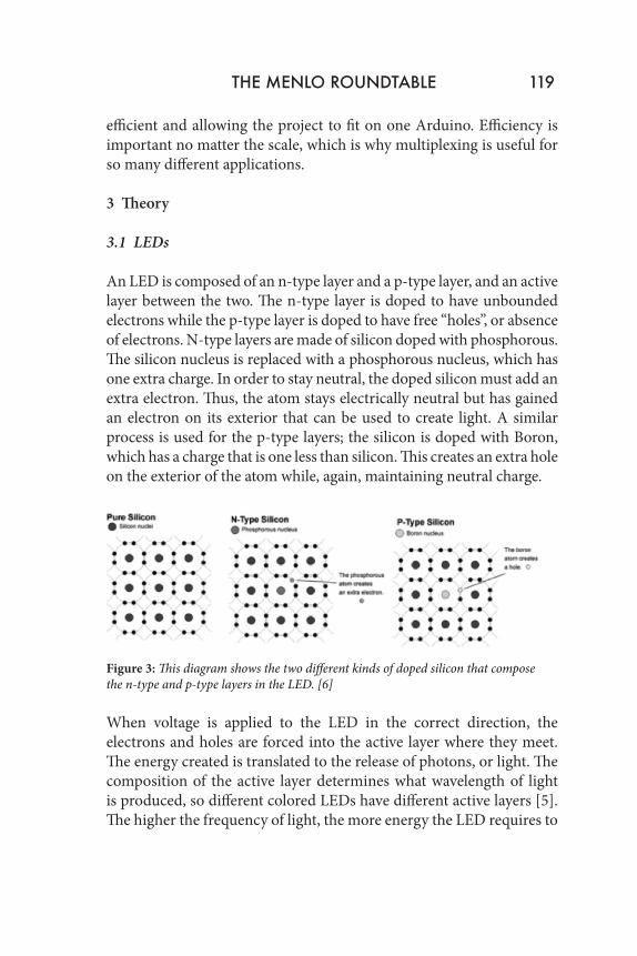
An LED is composed of an n-type layer and a p-type layer, and an active layer between the two. The n-type layer is doped to have unbounded electrons while the p-type layer is doped to have free “holes”, or absence of electrons. N-type layers are made of silicon doped with phosphorous. The silicon nucleus is replaced with a phosphorous nucleus, which has one extra charge. In order to stay neutral, the doped silicon must add an extra electron. Thus, the atom stays electrically neutral but has gained an electron on its exterior that can be used to create light. A similar process is used for the p-type layers; the silicon is doped with Boron, which has a charge that is one less than silicon. This creates an extra hole on the exterior of the atom while, again, maintaining neutral charge.
Figure 3: This diagram shows the two different kinds of doped silicon that compose the n-type and p-type layers in the LED. [6]
When voltage is applied to the LED in the correct direction, the electrons and holes are forced into the active layer where they meet. The energy created is translated to the release of photons, or light. The composition of the active layer determines what wavelength of light is produced, so different colored LEDs have different active layers [5]. The higher the frequency of light, the more energy the LED requires to
120 Michelle Meyer
produce this light. This is because the energy of one electron is equal to the voltage across the LED divided by the electron’s charge (by V = E*q). This energy corresponds to the energy of the emitted photon, and it can be rewritten as E = h*f, where h is Planck’s constant. This shows that there is a direct relationship between energy and frequency of light. Thus, since red light has a relatively low frequency compared to blue light, red LEDs require less energy than blue LEDs. [7]
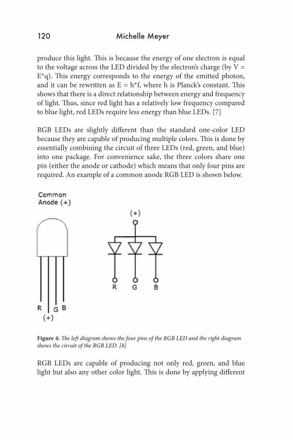
RGB LEDs are slightly different than the standard one-color LED because they are capable of producing multiple colors. This is done by essentially combining the circuit of three LEDs (red, green, and blue) into one package. For convenience sake, the three colors share one pin (either the anode or cathode) which means that only four pins are required. An example of a common anode RGB LED is shown below.
Figure 4: The left diagram shows the four pins of the RGB LED and the right diagram shows the circuit of the RGB LED. [8]
RGB LEDs are capable of producing not only red, green, and blue light but also any other color light. This is done by applying different
THE MENLO ROUNDTABLE 121
intensities of voltages to each of the three pins. For the purpose of this project, only red light and blue light are needed so the green pin is cut off of each LED.
The LEDs used in this project are diffused, which means that the viewing angle is wider than normal. The viewing angle of non-diffused LEDs is generally 12 degrees while the viewing angle of diffused LEDs is typically 35 degrees [9]. Diffused LEDs are generally dimmer because the light is spread over a larger area, but for this project it is more important to have a larger viewing angle than brighter light.
3.2 Choosing the Resistor
LEDs will burn out when too much current is run through them, so it is important to have a resistor in series with the LED. When current runs through a resistor, it goes through many wire windings that dissipate heat. This loss of power reduces the amount of current, which will prevent the LED from burning out [10]. However, it is also important that not too much heat is dissipated by the resistor because that would be a waste of power that could be otherwise used to make the LED brighter. Thus, the best resistor to use is one with just enough resistance to prevent the LED from burning out because it allows the LED to function at its brightest state.
The current through the LED should be 20mA. The typical voltage across the LED when it emits blue light is different from when it emits red light (3.2V and 2.0V respectively) so the limiting case was considered [11]. The lower voltage (2.0V) is the limiting case because that means there must be a higher voltage drop across the resistor. The voltage drop across the resistor is equal to the total voltage supplied (5.0V) subtracted by the voltage across the LED. Ohm’s Law, V = IR , or R = V/I, can be used to calculate the resistance needed: R = (5V-2V)/0.02A= 150Ω. Rounding up to the next value that is available leads to the 180Ω resistor. These are placed in front of each row in the matrix.
122 Michelle Meyer
3.3 Resistor Rows and Columns
There are 10 rows and 10 columns for each player’s board. For each of the rows and columns, there are 10 resistors for each of the 10 spaces. Each of these resistors have a different value. Each ship has a wire in it that goes through the two pegs so that when it is placed on the board, it comes into contact with the series of resistors. The wire has negligible resistance, so the current travels through the wire, shorting the resistors over which it is placed. The design of the ship limits the placement of the pegs, so the two pegs are spaced apart by one less than the number of spaces that the ship occupies. For example, when placed onto the board, a submarine (3 spaces long) will short two resistors under it. The resistance of the entire row would then be less by the sum of those two resistances. Because there are 10 unique resistances across the 10 spots, the sum of missing resistances is unique depending on where in the row or column the ship is placed. Therefore, in order to detect what the ship position of a row or column is, the unique value of total resistance can be matched to the position.
In order to find the total missing resistance, an additional resistor is placed at the beginning of the series and the connection to the Arduino’s analog input is at this junction. The Arduino reads in the voltage and uses the known resistance of the additional resistor to calculate the resistance of the rest of the series. The resistance of this extra resistor was selected so that it would have a voltage drop of at least 1.7V at all times. This is done so that 5V can be used as the total voltage in the series while 3.3V remains the reference voltage. The input voltage to the Arduino must be below 3.3V for two reasons: the first is that 3.3V is the maximum detectable voltage (due to 3.3V being the reference voltage) and the second is that the Arduino will blow out if a voltage above 3.3V is inputted. The purpose of using a larger total voltage and a smaller reference voltage is to increase accuracy by maximizing the range of analog values. If the highest input voltage is around 3.3V, the full range of 0-4095 is being used. The total resistance (not including
THE MENLO ROUNDTABLE 123
the extra resistor) is about 5660Ω, so the extra resistor can be found using Ohm’s law:
Itot = Vtot/Rtot = V1/ Rextra
5V/(5600+ Rextra) = 1.7V/ Rextra
Rextra = 2,885Ω
The next value up, 3300Ω is used.
In order to find the resistance during the ship-detection phase, Ohm’s law is used once again. This voltage input is equal to the voltage drop across the resistor row/column, which can be used to find the resistance. Since current is equal in series, Itot = Vtot/Rtot = Vin/Rremaining.
Rtot = Rremaining + Rfirst
Rremaining = (Rremaining + Rfirst) * Vin/Vtot = Rremaining * Vin/Vtot + Rfirst * Vin/Vtot
Rremaining * (1 - Vin/Vtot) = Rfirst * Vin/Vtot
Rremaining = (Rfirst* Vin)/(Vtot * (1 - Vin/Vtot) )
Rremaining = (Rfirst* Vin)/(Vtot * (Vtot - Vin)
3.4 Arduino
The Arduino is a microcontroller board that is used as the brains of this project. The Arduino used for this project is the Arduino Due. There are 54 digital input and output pins. When the pins are set to input mode, each one can be set to HIGH or LOW (a setting of HIGH will send out voltage). There are 12 analog inputs, which differ from the digital output pins in that they read in specific voltage values instead of HIGH or LOW [12]. This is used for detecting the ships’ positions because different voltage values correspond to different ship positions.
124 Michelle Meyer
The Arduino Due has the ability to read analog inputs with 12-bit resolution, which is four times better than the 10-bit resolution of an Arduino Uno [12, 13]. This, along with the large number of pins, is the main reason for the choice to use the Arduino Due. Another benefit is the faster speed (84 MHz versus 16 MHz), though the slower speed would have been adequate [8, 9]. The speed of the Arduino just needs to be faster than the fastest speed that the eye can detect so that the LEDs don’t appear to be flickering, and both speeds are well above this. 3.5 Multiplexing
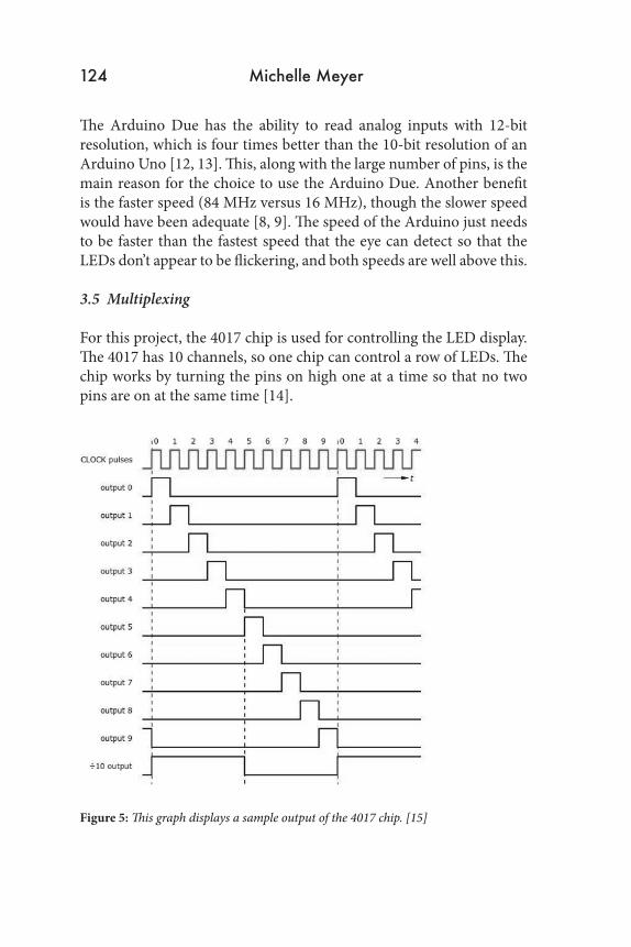
For this project, the 4017 chip is used for controlling the LED display. The 4017 has 10 channels, so one chip can control a row of LEDs. The chip works by turning the pins on high one at a time so that no two pins are on at the same time [14].
Figure 5: This graph displays a sample output of the 4017 chip. [15]
THE MENLO ROUNDTABLE 125
The frequency is set externally, in this case by the Arduino. The Arduino triggers the 4017 to move to the next output by sending a high voltage to the clock pin. After all 10 rows are complete, the reset pin is triggered using a high voltage, which starts the cycle over again. The LEDs appear to be lit simultaneously if the frequency is set higher than the speed that the eye can detect. [16].
An opposite process is used for detecting the ships’ positions: instead of staggering the voltage outputs, the voltage inputs are staggered so that many can be read using only one analog input pin. The multiplexer used has 16 channels, meaning that 16 different voltages can be read in using the one input pin. The channels are controlled using 4 digital pins. The Arduino sends high or low voltages to these 4 pins, and the combination of high and low voltages is the binary version of the channel number. The channel number that is represented by the digital pins is the one being inputted to the analog input pin. For example, in order to read in the voltage in channel 9, the digital pins must be high and low as follows: 1001.
3.6 Putting It Together
There are four LED matrices in total because each player sees both the hits and misses on their own layout and the hits and misses on their opponent’s layout. However, in terms of sending the light outputs, it can be thought of as just two matrices: one for each layout. In terms of the physical circuit, the two matrices that are mirrors of each other can be put in parallel with each other. This reduces the number of pins and amount of work to be done by the Arduino.
4 Design
4.1 Circuit
The circuit for the game can be split up into 3 main parts: reading in the ships’ positions, displaying the correct LED lights, and reading in the guesses while updating the LED matrix. The first step of the game is to place the ships. The ships each have a wire through the two pegs, and when the ships are placed down, the wires make contact with a row
126 Michelle Meyer
or column of resistors. The wire in the ship has negligible resistance, so the current travels through the wire instead of the resistors between the pegs. Since some of the resistors are shorted, the total resistance of the row or column decreases. This decrease in resistance is used to find the ship’s position.
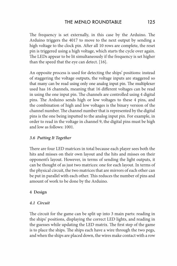
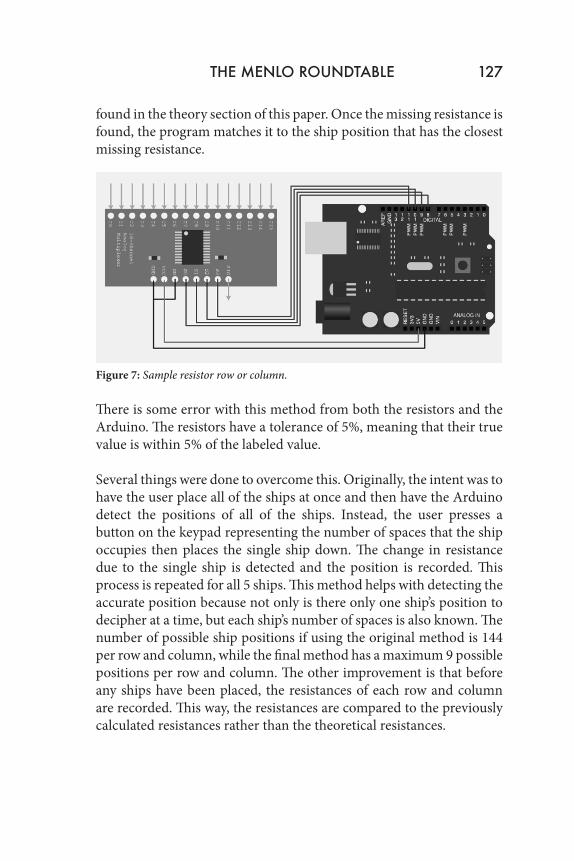
The Arduino runs through and reads in the voltage values for each row and column. This is done using multiplexing in order to minimize the number of pins used by the Arduino. The CD74HC4067 chip is used in order to do so. A diagram of how the chip is used is shown in fugure 6. The chip is connected to 4 different digital output pins. The voltage readings are cycled through very quickly, so the entire process of reading the 16 channels is not significantly longer than reading in 16 individual analog inputs.
Figure 6: Sample use of the CD74HC4067 multiplexing chip.
The voltage values that are being read in correspond with a missing resistance. Missing resistance comes from a ship being placed across the resistor row or column: if part of the row or column is short circuited, its resistance decreases by the amount that was shorted. Each row or column is made up of 10 different resistors (or effectively 10 resistors - some are combined in series or parallel to achieve the desired value). These resistance values were chosen because they minimized the number of combinations that had similar voltage values. The calculation of the missing resistance based on the voltage input can be
THE MENLO ROUNDTABLE 127
found in the theory section of this paper. Once the missing resistance is found, the program matches it to the ship position that has the closest missing resistance.
Figure 7: Sample resistor row or column.
There is some error with this method from both the resistors and the Arduino. The resistors have a tolerance of 5%, meaning that their true value is within 5% of the labeled value.
Several things were done to overcome this. Originally, the intent was to have the user place all of the ships at once and then have the Arduino detect the positions of all of the ships. Instead, the user presses a button on the keypad representing the number of spaces that the ship occupies then places the single ship down. The change in resistance due to the single ship is detected and the position is recorded. This process is repeated for all 5 ships. This method helps with detecting the accurate position because not only is there only one ship’s position to decipher at a time, but each ship’s number of spaces is also known. The number of possible ship positions if using the original method is 144 per row and column, while the final method has a maximum 9 possible positions per row and column. The other improvement is that before any ships have been placed, the resistances of each row and column are recorded. This way, the resistances are compared to the previously calculated resistances rather than the theoretical resistances.
128 Michelle Meyer
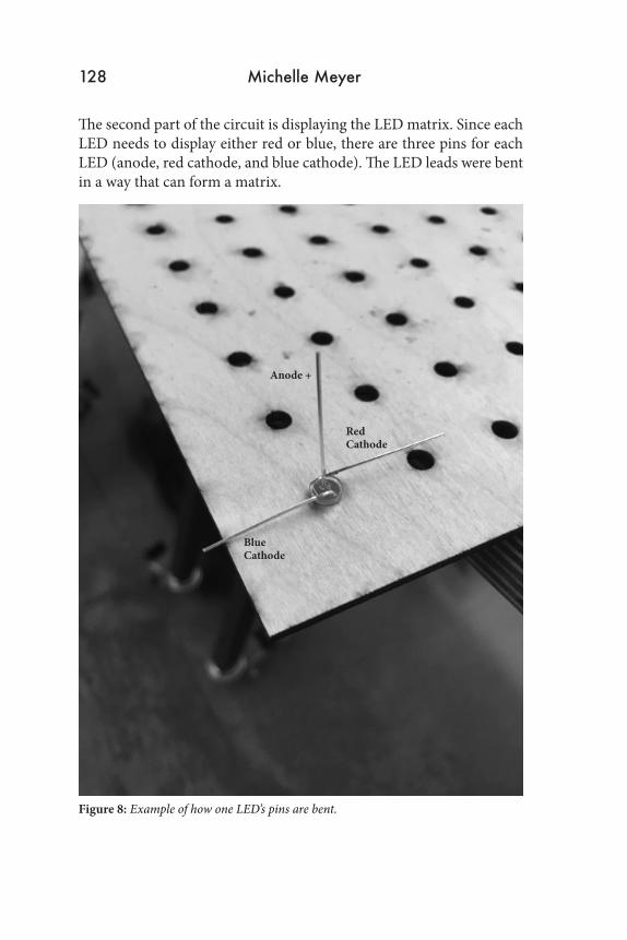
The second part of the circuit is displaying the LED matrix. Since each LED needs to display either red or blue, there are three pins for each LED (anode, red cathode, and blue cathode). The LED leads were bent in a way that can form a matrix.
Figure 8: Example of how one LED’s pins are bent.
Anode +
RedCathode
BlueCathode
THE MENLO ROUNDTABLE 130
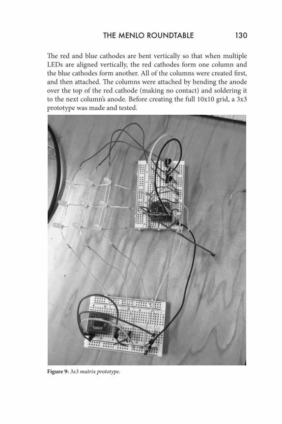
The red and blue cathodes are bent vertically so that when multiple LEDs are aligned vertically, the red cathodes form one column and the blue cathodes form another. All of the columns were created first, and then attached. The columns were attached by bending the anode over the top of the red cathode (making no contact) and soldering it to the next column’s anode. Before creating the full 10x10 grid, a 3x3 prototype was made and tested.
Figure 9: 3x3 matrix prototype.
130 Michelle Meyer
After the prototype was tested, a 10x10 grid was created with this setup. This setup gives each of the LEDs the capability to light up red or blue based on whether voltage is applied to its row and whether voltage is allowed to flow through either the red or blue column. Transistors are used for each of the columns in order to block or allow current to flow. The NPN transistor has one pin (collector) connected to the LED cathode, the emitter is connected to ground, and the base is connected to the Arduino input. Thus, if a certain row has voltage applied to it and one of the transistors has a voltage applied to the base, the LED corresponding to this row and column lights up.
It is important to only light up one row or one column at a time otherwise more LEDs will be lit up than the system can handle. A 4017 decade counter is used to delay and space out the lighting of each column. The decade counter sends one output at a time for 10 different outputs, so one 4017 is used for each of the cathode columns. One step is started by applying voltage to the correct rows. For example, if the first two spaces in that column need to be lit up, voltage will be applied to the first two rows of the matrix. After a small delay, the voltage is set back to zero for all pins, and a signal is sent to the decade counter to advance to the next column. The program looks at its stored 2D array to figure out which lights in that column need to be lit, and voltage is applied to those rows. This is repeated until all 10 columns are done. One color runs through first and then the second color runs (using the other column and other decade counter). In order to control which color is being displayed, the grounds of each decade counter are connected to an NPN transistor. The bases of the transistors are connected to an Arduino digital output pin so that when the pin is high, that color is displayed on the matrix.
The decade counter and program run at a rapid pace so that the blinking of the LEDs is not visible to the human eye; the LEDs appear to be continuously lit.
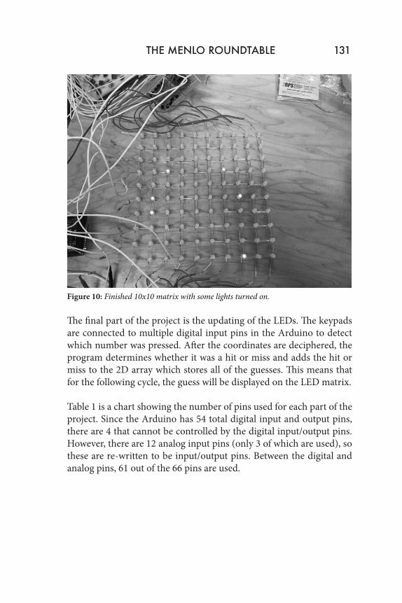
Figure 10: Finished 10x10 matrix with some lights turned on.
The final part of the project is the updating of the LEDs. The keypads are connected to multiple digital input pins in the Arduino to detect which number was pressed. After the coordinates are deciphered, the program determines whether it was a hit or miss and adds the hit or miss to the 2D array which stores all of the guesses. This means that for the following cycle, the guess will be displayed on the LED matrix.
Table 1 is a chart showing the number of pins used for each part of the project. Since the Arduino has 54 total digital input and output pins, there are 4 that cannot be controlled by the digital input/output pins. However, there are 12 analog input pins (only 3 of which are used), so these are re-written to be input/output pins. Between the digital and analog pins, 61 out of the 66 pins are used.
THE MENLO ROUNDTABLE 131

Use Number of Pins UsedLED matrix rows 204017 Reset pins 44017 clock pins 4Red on output 2Blue on output 2Keypad input 14CD74HC4067 digital signals 12Total: 58
Table 1: Shows the number of pins used for each part of the circuit.
132 Michelle Meyer
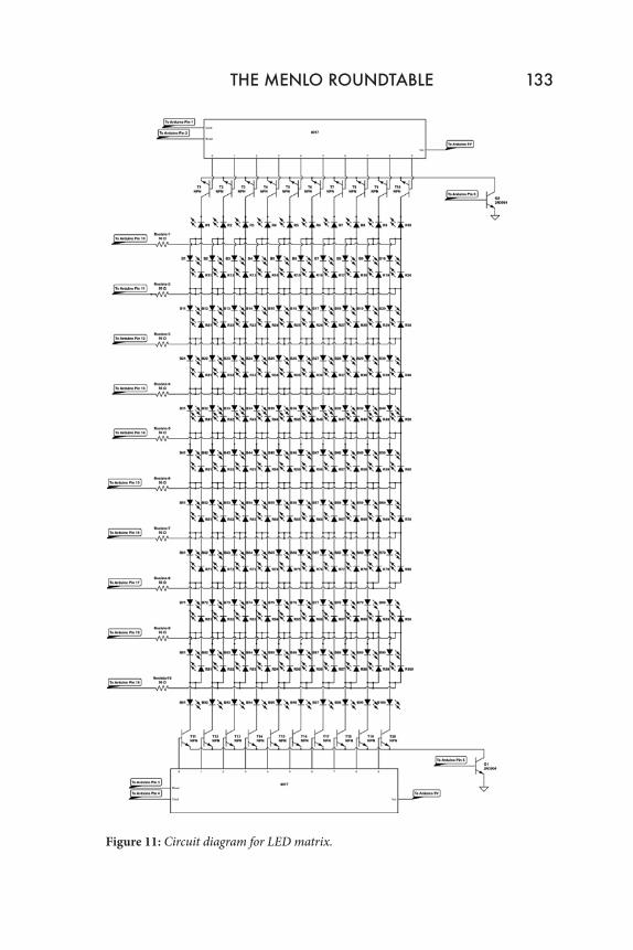
Figure 11: Circuit diagram for LED matrix.
THE MENLO ROUNDTABLE 133
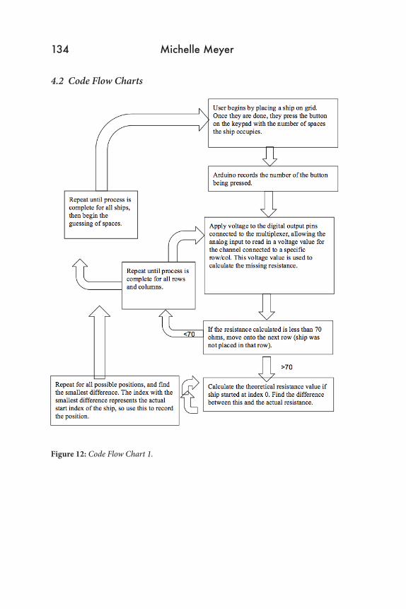
4.2 Code Flow Charts
Figure 12: Code Flow Chart 1.
134 Michelle Meyer
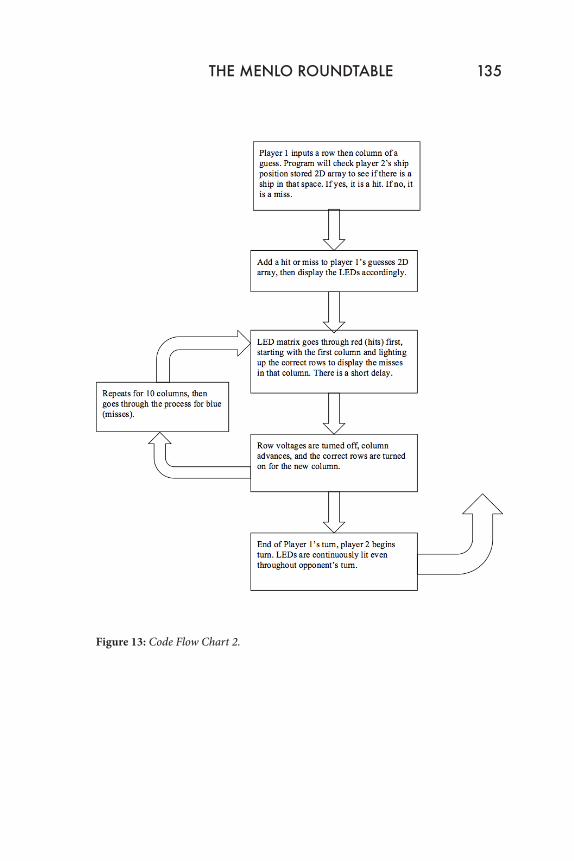
THE MENLO ROUNDTABLE 135
Figure 13: Code Flow Chart 2.
4.3 Game Board
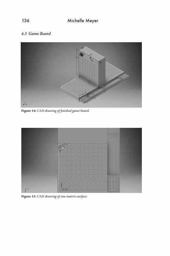
Figure 14: CAD drawing of finished game board.
Figure 15: CAD drawing of one matrix surface.
136 Michelle Meyer
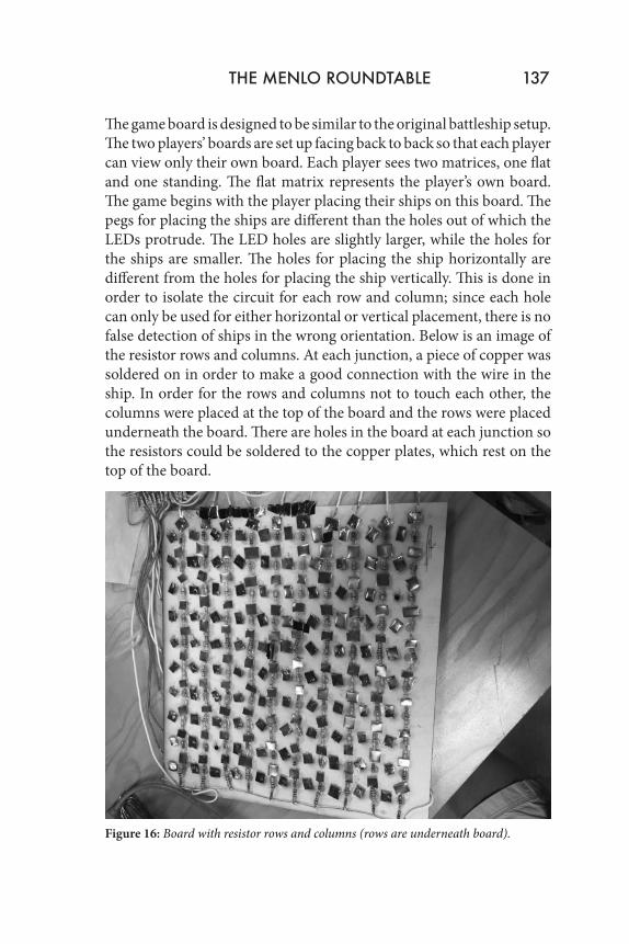
The game board is designed to be similar to the original battleship setup. The two players’ boards are set up facing back to back so that each player can view only their own board. Each player sees two matrices, one flat and one standing. The flat matrix represents the player’s own board. The game begins with the player placing their ships on this board. The pegs for placing the ships are different than the holes out of which the LEDs protrude. The LED holes are slightly larger, while the holes for the ships are smaller. The holes for placing the ship horizontally are different from the holes for placing the ship vertically. This is done in order to isolate the circuit for each row and column; since each hole can only be used for either horizontal or vertical placement, there is no false detection of ships in the wrong orientation. Below is an image of the resistor rows and columns. At each junction, a piece of copper was soldered on in order to make a good connection with the wire in the ship. In order for the rows and columns not to touch each other, the columns were placed at the top of the board and the rows were placed underneath the board. There are holes in the board at each junction so the resistors could be soldered to the copper plates, which rest on the top of the board.
Figure 16: Board with resistor rows and columns (rows are underneath board).
THE MENLO ROUNDTABLE 137
Also below the game board is the LED matrix. This is below the game board but above the resistors. There is enough room between the two layers so that no contact is made. The LED matrix sticks up through the larger holes and displays the colors representing the hit or miss. The LEDs are visible even through the placed ships because the ships are be designed to have holes so that the LEDs fit through and are visible from the top. The standing matrix represents the opponent’s board. The same LEDs are lit as the opponent’s flat board, but the ships won’t be visible.
The game board also includes a side container for the ships when not in use. This container is next to the keypad, which the users utilize to enter their guesses. The board has the numbers for the coordinate system laser cut onto them so the user can easily determine the code for their keypad entry.
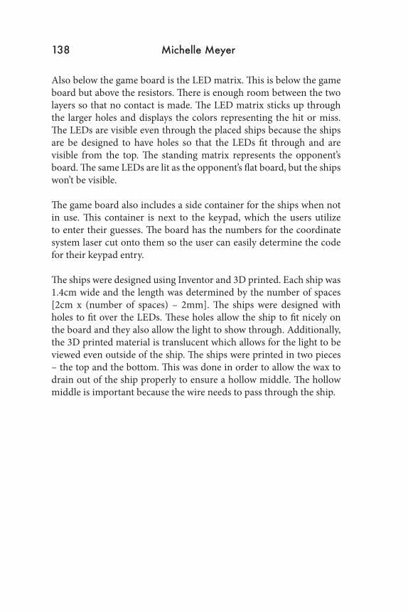
The ships were designed using Inventor and 3D printed. Each ship was 1.4cm wide and the length was determined by the number of spaces [2cm x (number of spaces) – 2mm]. The ships were designed with holes to fit over the LEDs. These holes allow the ship to fit nicely on the board and they also allow the light to show through. Additionally, the 3D printed material is translucent which allows for the light to be viewed even outside of the ship. The ships were printed in two pieces – the top and the bottom. This was done in order to allow the wax to drain out of the ship properly to ensure a hollow middle. The hollow middle is important because the wire needs to pass through the ship.
138 Michelle Meyer

Figure 17: CAD drawing of 2-piece ship.
Figure 18: CAD drawing of 3-piece ship.
THE MENLO ROUNDTABLE 139
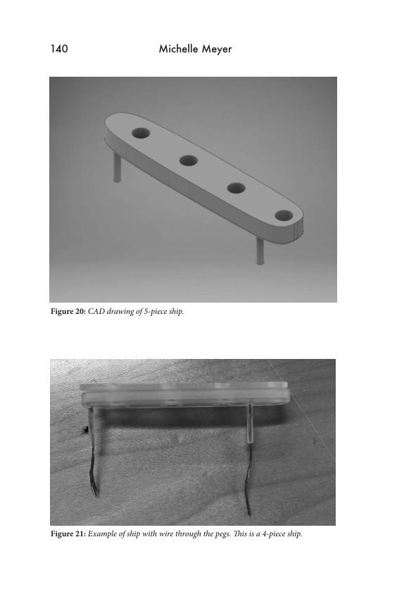
Figure 19: CAD drawing of 4-piece ship.
Figure 20: CAD drawing of 5-piece ship.
Figure 21: Example of ship with wire through the pegs. This is a 4-piece ship.
140 Michelle Meyer
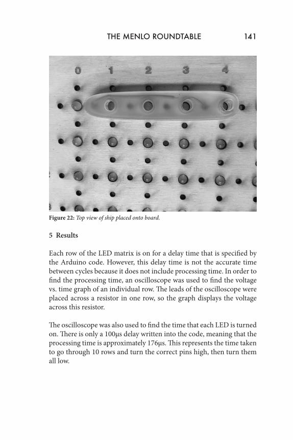
Figure 22: Top view of ship placed onto board.
5 Results
Each row of the LED matrix is on for a delay time that is specified by the Arduino code. However, this delay time is not the accurate time between cycles because it does not include processing time. In order to find the processing time, an oscilloscope was used to find the voltage vs. time graph of an individual row. The leads of the oscilloscope were placed across a resistor in one row, so the graph displays the voltage across this resistor.
The oscilloscope was also used to find the time that each LED is turned on. There is only a 100µs delay written into the code, meaning that the processing time is approximately 176µs. This represents the time taken to go through 10 rows and turn the correct pins high, then turn them all low.
THE MENLO ROUNDTABLE 141
142 Michelle Meyer
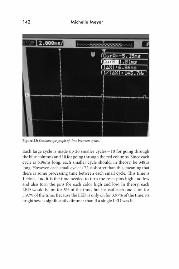
Figure 23: Oscilloscope graph of time between cycles.
Each large cycle is made up 20 smaller cycles—10 for going through the blue columns and 10 for going through the red columns. Since each cycle is 6.96ms long, each smaller cycle should, in theory, be 348µs long. However, each small cycle is 72µs shorter than this, meaning that there is some processing time between each small cycle. This time is 1.44ms, and it is the time needed to turn the reset pins high and low and also turn the pins for each color high and low. In theory, each LED would be on for 5% of the time, but instead each one is on for 3.97% of the time. Because the LED is only on for 3.97% of the time, its brightness is significantly dimmer than if a single LED was lit.
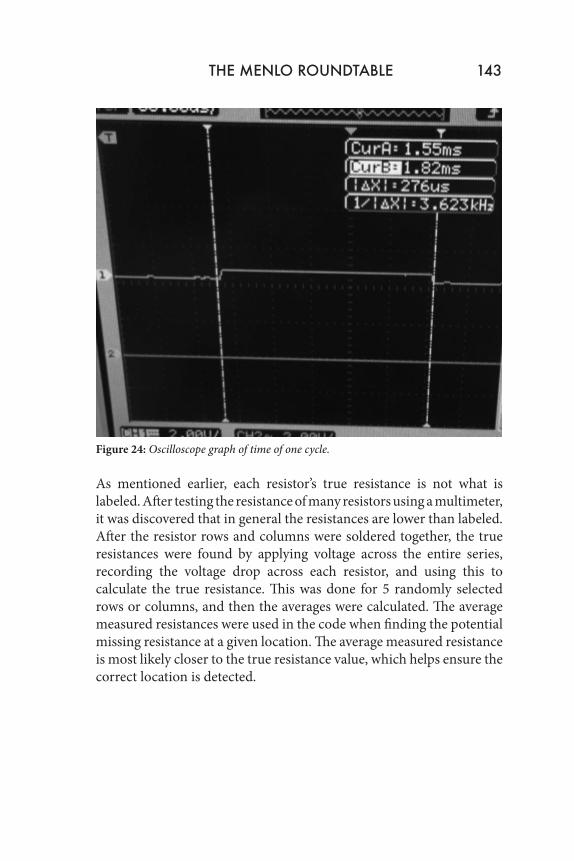
Figure 24: Oscilloscope graph of time of one cycle.
As mentioned earlier, each resistor’s true resistance is not what is labeled. After testing the resistance of many resistors using a multimeter, it was discovered that in general the resistances are lower than labeled. After the resistor rows and columns were soldered together, the true resistances were found by applying voltage across the entire series, recording the voltage drop across each resistor, and using this to calculate the true resistance. This was done for 5 randomly selected rows or columns, and then the averages were calculated. The average measured resistances were used in the code when finding the potential missing resistance at a given location. The average measured resistance is most likely closer to the true resistance value, which helps ensure the correct location is detected.
THE MENLO ROUNDTABLE 143
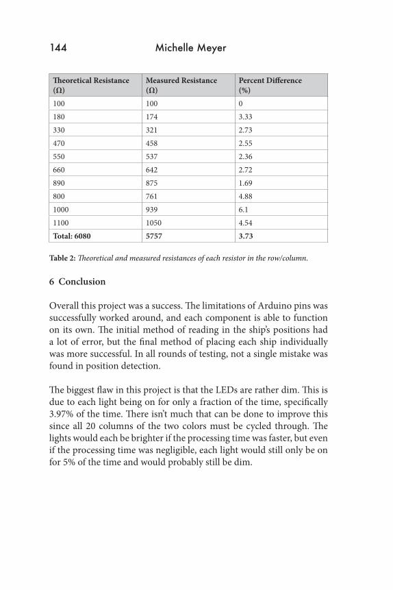
Theoretical Resistance (Ω)
Measured Resistance (Ω)
Percent Difference (%)
100 100 0180 174 3.33330 321 2.73470 458 2.55550 537 2.36660 642 2.72890 875 1.69800 761 4.881000 939 6.11100 1050 4.54Total: 6080 5757 3.73
Table 2: Theoretical and measured resistances of each resistor in the row/column.
6 Conclusion
Overall this project was a success. The limitations of Arduino pins was successfully worked around, and each component is able to function on its own. The initial method of reading in the ship’s positions had a lot of error, but the final method of placing each ship individually was more successful. In all rounds of testing, not a single mistake was found in position detection.
The biggest flaw in this project is that the LEDs are rather dim. This is due to each light being on for only a fraction of the time, specifically 3.97% of the time. There isn’t much that can be done to improve this since all 20 columns of the two colors must be cycled through. The lights would each be brighter if the processing time was faster, but even if the processing time was negligible, each light would still only be on for 5% of the time and would probably still be dim.
144 Michelle Meyer
This project demonstrates methods of efficiently outputting and detecting large amounts of information with a small number of outputs and inputs. There are 400 total LEDs and 144 possible ship positions for each of the 40 rows and columns, and all of this was controlled and detected by 58 pins on the Arduino. However, compared to many electronic technologies today, this is still considered an extremely small scale. The size of data transfers in the world of electronics is ever-increasing, which makes these methods of efficiently controlling and detecting information extremely important. Possibly even more important is the fact that this game makes it impossible to cheat, which could be the cause or solution to many family arguments. 7 The Next Step
If I were to continue this project, I would want to add some features to make it more user-friendly. I would add an LCD screen to display messages to confirm with the user. After a ship is placed, the LCD screen could display the row and column of the front of the ship to confirm. Also, the LCD screen could display the coordinates of a guess before it is sent in. This would help the game flow better because with the current code, the inputs are immediately stored and can’t be changed if it was read in wrong. Additionally, a speaker could be added to play an explosion sound when a ship is hit. 8 Acknowledgements
Thank you Dr. Dann for teaching this great course and giving advice when needed but also giving us the independence to explore our projects. Thank you Mr. Ward for your help in the tool shop. Thank you Parker Callender for making the long hours in the lab more entertaining and for staying up with me as I write this. Thank you Parvathi Narayan, Andy Parker, and David Roy for their support, Arduino cables, and multimeters.
THE MENLO ROUNDTABLE 145
9 Citations
[1] Edison Tech Center “LEDs and OLEDs”, http://www.edisontechcenter.org/LED.html (Accessed February 7, 2016).
[2] Craford, M. George; Holonyak, Nick; Kish, Frederick A. “In Pursuit of the Ultimate Lamp”, Scientific American.
[3] Image, http://blog.zulyusof.com/wp-content/uploads/2010/08/DWDM-functional-schematic.jpg, (Accessed March 22, 2016).
[4] Image, https://upload.wikimedia.org/wikipedia/commons/thumb/f/f1/Frequenzmultiplex001.svg/400px-Frequenzmultiplex001.svg.png, (Accessed March 22, 2016).
[5] EdgeFX “Types of Multiplexers and Multiplexing in Mobile Network” http://www.edgefxkits.com/blog/know-all-about-multiplexing-in-mobile-network/ (Accessed February 7, 2016).
[6] Image, http://media.tumblr.com/tumblr_lgnp3rKeUF1qf00w4.gif, (Accessed March 22, 2016).
[7]http://chemwiki.ucdavis.edu/Core/Materials_Science/Semiconductors/Light_Emitting_Diodes#Band_Gap_and_Photon_Wavelength_Relation (Accessed March 22, 2016).
[8] Image, http://mklec.com/image/data/diodes/led/common_anode_rgb_led_pinout.png (Accessed February 7, 2016).
[9] Dialight “Getting to Know LEDs, Applications, and Solutions”, http://www.dialight.com/Assets%5CApplication_Notes%5CIndication%5CGetting%20To%20Know%20LEDs.PDF (Accessed February 7, 2016).
[10] All About Circuits, “Resistors”, http://www.allaboutcircuits.com/textbook/direct-current/chpt-2/resistors/ (Accessed February 7, 2016).
146 Michelle Meyer

[11] Sparkfun, “Red/Green/Blue Triple Color LED”, http://cdn.sparkfun.com/datasheets/Components/LED/YSL-R596AR3G4B5C-C10.pdf (Accessed February 7, 2016).
[12] Arduino, “Arduino Due”, https://www.arduino.cc/en/Main/ArduinoBoardDue (Accessed February 7, 2016)
[13] Arduino, “Arduino Uno”, https://www.arduino.cc/en/Main/ArduinoBoardDue (Accessed February 7, 2016)
[14] Learning about Electronics, “How to Build a Decade Counter Circuit with a 4017”, http://www.learningaboutelectronics.com/Articles/Decade-counter-circuit-with-4017.php (Accessed February 7, 2016)
[15] Image, http://cdn.instructables.com/FLJ/5VP4/HSGFWHXM/FLJ5VP4HSGFWHXM.MEDIUM.jpg (Accessed February 7, 2016).
[16] DIY Hacking, “Build an Arduino LED Matrix in 3 Simple Steps”, http://diyhacking.com/arduino-led-matrix/ (Accessed February 7, 2016).
THE MENLO ROUNDTABLE 147