electromagnetic single-disc friction clutches single-disc frictio… · electromagnetic single-disc...
TRANSCRIPT
ELECTROMAGNETIC SINGLE-DISC FRICTION CLUTCHES
Catal
ogue
No.
: V/C/15/02
Type EBF
Optional On Request
2
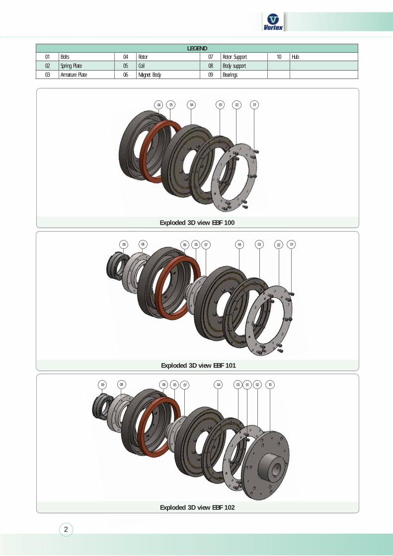
Exploded 3D view EBF 102
LEGEND01 Bolts 04 Rotor 07 Rotor Support 10 Hub
02 Spring Plate 05 Coil 08 Body support
03 Armature Plate 06 Magnet Body 09 Bearings
03 02040506 01
03 02040705 010809 06
03 02040705 100809 06 01
Exploded 3D view EBF 100
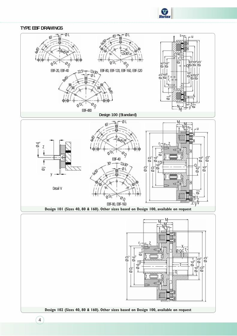
Exploded 3D view EBF 101
3
The said distance to the surrounding components can either be achieved by corre-sponding air gap or by usage of non-magnetic materials, such as aluminum, brass, etc. During assembly, ensure minimum possible radial and axial offset in the position of the components relative to each other. Maximum allowable value would be 0.2 mm. The variation in the air-gap over the entire periphery should ideally also not exceed 0.1 mm.
1. Designed and Tested in compliance to DIN VDE 0580 standards
2. Compact sized design for corresponding torque ratings
3. Low operation times
4. Nitrided friction surfaces for long life
5. Construction Variants available to meet wide range of mounting and adaptation requirements
6. High operation frequency permitted
7. Zero Idling torque
8. Zero backlash in torque transmission due to diaphragm spring
9. Maintenance Free
10. Steel-Steel Friction combination
11. Dry operation usage as standard, wet operation also permitted
12. Greater wear resistance and protection against corrosion
13. Class ‘H’ insulation system to 180°C
14. These Clutches require the friction surfaces to be bedded-in before they can reach the rated transmissible torque values
TYPE EBF
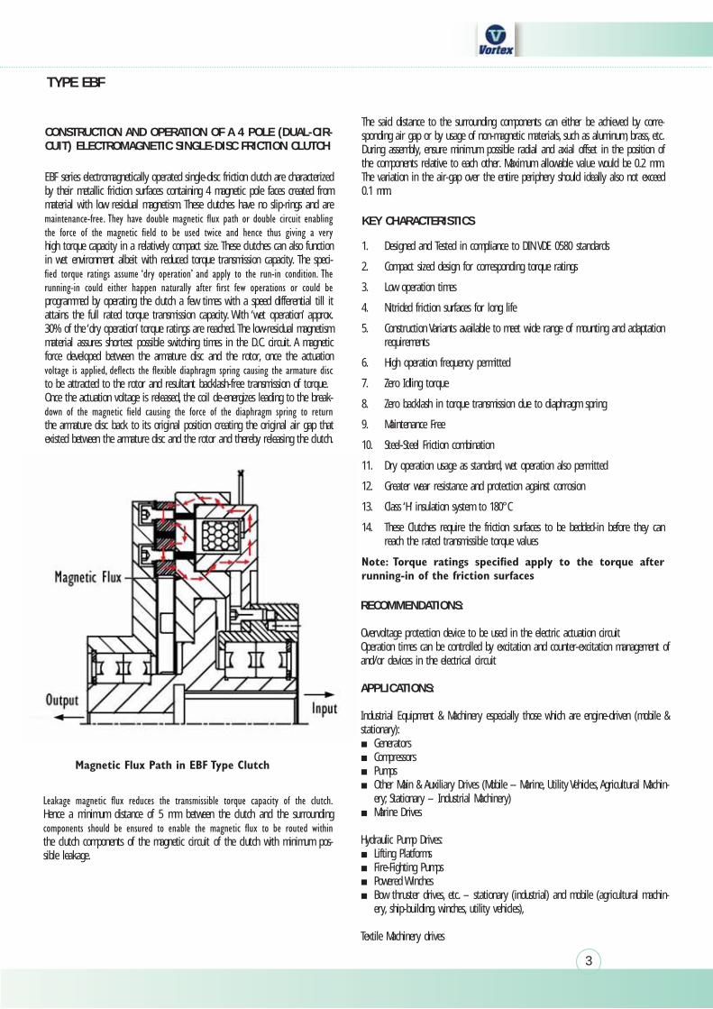
CONSTRUCTION AND OPERATION OF A 4 POLE (DUAL-CIR-CUIT) ELECTROMAGNETIC SINGLE-DISC FRICTION CLUTCH
KEY CHARACTERISTICS
EBF series electromagnetically operated single-disc friction clutch are characterized by their metallic friction surfaces containing 4 magnetic pole faces created from material with low residual magnetism. These clutches have no slip-rings and are
high torque capacity in a relatively compact size. These clutches can also function in wet environment albeit with reduced torque transmission capacity. The speci-
programmed by operating the clutch a few times with a speed differential till it attains the full rated torque transmission capacity. With ‘wet operation’ approx. 30% of the ‘dry operation’ torque ratings are reached. The low-residual magnetism material assures shortest possible switching times in the D.C. circuit. A magnetic force developed between the armature disc and the rotor, once the actuation
to be attracted to the rotor and resultant backlash-free transmission of torque.Once the actuation voltage is released, the coil de-energizes leading to the break-
the armature disc back to its original position creating the original air gap that existed between the armature disc and the rotor and thereby releasing the clutch.
RECOMMENDATIONS:
Overvoltage protection device to be used in the electric actuation circuitOperation times can be controlled by excitation and counter-excitation management of and/or devices in the electrical circuit
APPLICATIONS:
Industrial Equipment & Machinery especially those which are engine-driven (mobile & stationary): Generators Compressors Pumps Other Main & Auxiliary Drives (Mobile -- Marine, Utility Vehicles, Agricultural Machin-ery; Stationary – Industrial Machinery)
Marine Drives
Hydraulic Pump Drives: Lifting Platforms Fire-Fighting Pumps Powered Winches Bow thruster drives, etc. – stationary (industrial) and mobile (agricultural machin-ery, ship-building, winches, utility vehicles),
Textile Machinery drives
Dust Cover
Rotor
Hence a minimum distance of 5 mm between the clutch and the surrounding
the clutch components of the magnetic circuit of the clutch with minimum pos-sible leakage.
4
Design 100 (Standard)
TYPE EBF DRAWINGS
M0
M1
Z
y
Z1r2
M0Ns1s u
N yZ
u
Ø D 2
Ø d 1
Ø d 4
Ø D 4
Ø D 1
Ø d 6
Ø d 7
Ø d 2
Ø d 8
Ø d 3
Ø J 2
Ø J 3
Ø J 3
Ø d 9
Ø D 6
Ø D 8
Ø D 1
Ø d 12Ø
d 11
Ø D 7
Ø D 2
Ø J
Ø D 1
Ø d 6
Ø J
Ø d 4
Ø d 6
Ø D 4
Ø D 2
Ø D 7
Ø d 11
Ø d 9
Ø d 12
Ø J
r r1
s
Zy V
OO1
M2M1 M0
Z1 X1Ø Q T1
T
O1
0
r2
N ss1
Ø LØ L
Ø D3
Ø D3
Ø D3
Ø D3
Ø D3
Ø D 5
Ø D 5
Ø D 5
Ø D 5
Ø D 5
Ø L
Ø L
Ø L
Ø J 1
O1
4x45
o
45o
22.5o
45o45o
8x45 o
12x30 o
12x30 o
8x45 o
12x30o
EBF-20, EBF-40
EBF-480
EBF-40
EBF-80, EBF-160
EBF-80, EBF-120, EBF-160, EBF-320
30o
6x30o
8x45o
6x30o
4x45
o
Detail V
Ø d 10
8x45 o
5
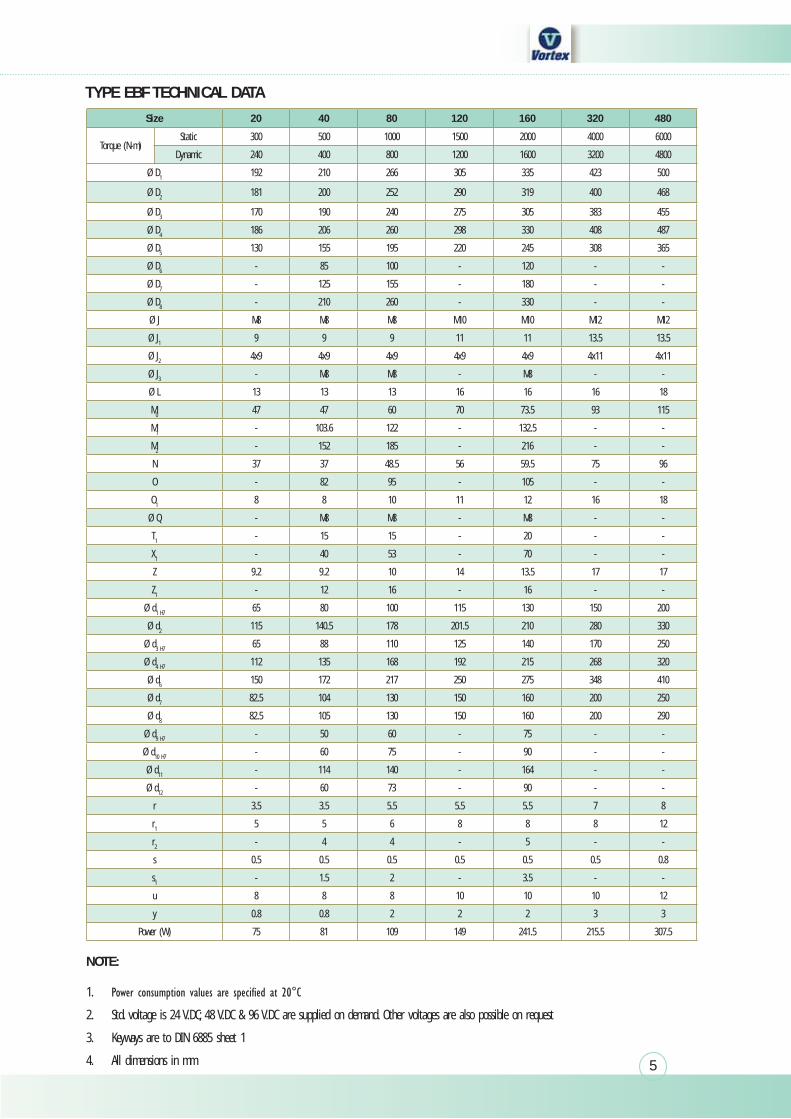
TYPE EBF TECHNICAL DATA
NOTE:
1.
2. Std. voltage is 24 V.DC; 48 V.DC & 96 V.DC are supplied on demand. Other voltages are also possible on request
3. Keyways are to DIN 6885 sheet 1
4. All dimensions in mm
Size 20 40 80 120 160 320 480
Torque (N-m)Static 300 500 1000 1500 2000 4000 6000
Dynamic 240 400 800 1200 1600 3200 4800
Ø D1 192 210 266 305 335 423 500
Ø D2 181 200 252 290 319 400 468
Ø D3 170 190 240 275 305 383 455
Ø D4 186 206 260 298 330 408 487
Ø D5 130 155 195 220 245 308 365
Ø D6 - 85 100 - 120 - -
Ø D7 - 125 155 - 180 - -
Ø D8 - 210 260 - 330 - -
Ø J M8 M8 M8 M10 M10 M12 M12
Ø J1 9 9 9 11 11 13.5 13.5
Ø J2 4x9 4x9 4x9 4x9 4x9 4x11 4x11
Ø J3 - M8 M8 - M8 - -
Ø L 13 13 13 16 16 16 18
M0 47 47 60 70 73.5 93 115
M1 - 103.6 122 - 132.5 - -
M2 - 152 185 - 216 - -
N 37 37 48.5 56 59.5 75 96
O - 82 95 - 105 - -
O1 8 8 10 11 12 16 18
Ø Q - M8 M8 - M8 - -
T1 - 15 15 - 20 - -
X1 - 40 53 - 70 - -
Z 9.2 9.2 10 14 13.5 17 17
Z1 - 12 16 - 16 - -
Ø d1 H7 65 80 100 115 130 150 200
Ø d2 115 140.5 178 201.5 210 280 330
Ø d3 H7 65 88 110 125 140 170 250
Ø d4 H7 112 135 168 192 215 268 320
Ø d6 150 172 217 250 275 348 410
Ø d7 82.5 104 130 150 160 200 250
Ø d8 82.5 105 130 150 160 200 290
Ø d9 H7 - 50 60 - 75 - -
Ø d10 H7 - 60 75 - 90 - -
Ø d11 - 114 140 - 164 - -
Ø d12 - 60 73 - 90 - -
r 3.5 3.5 5.5 5.5 5.5 7 8
r1 5 5 6 8 8 8 12
r2 - 4 4 - 5 - -
s 0.5 0.5 0.5 0.5 0.5 0.5 0.8
s1 - 1.5 2 - 3.5 - -
u 8 8 8 10 10 10 12
y 0.8 0.8 2 2 2 3 3
Power (W) 75 81 109 149 241.5 215.5 307.5
6
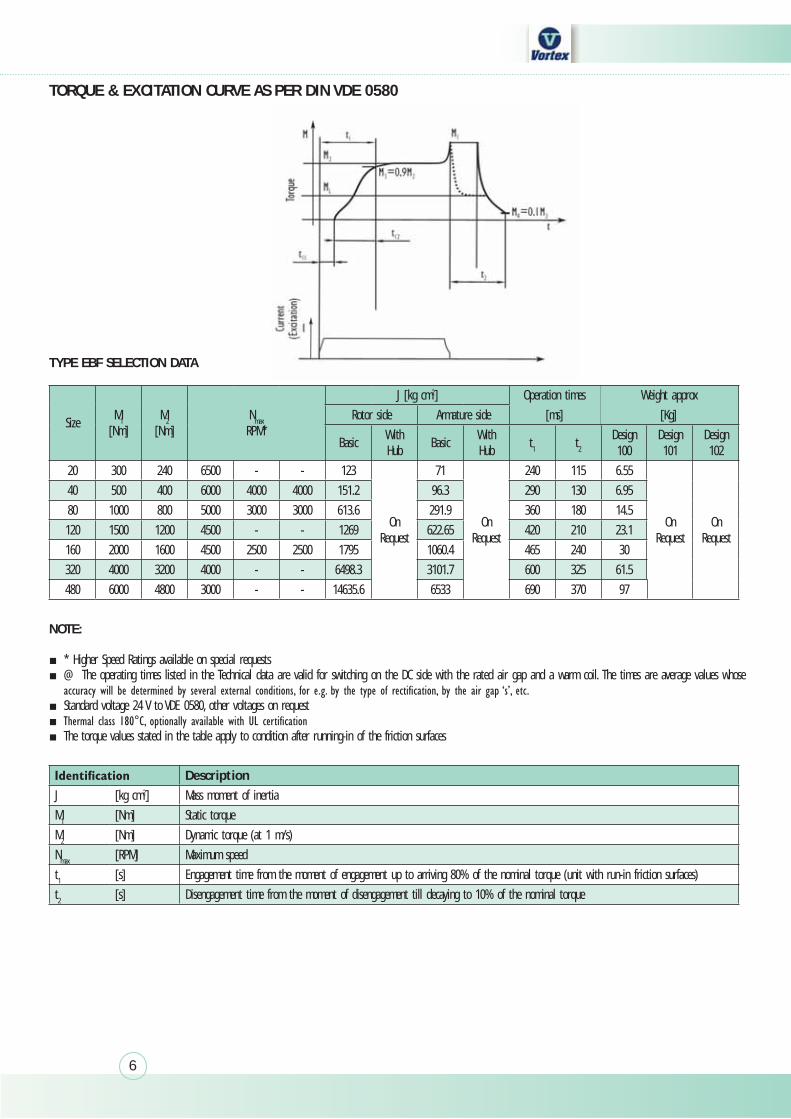
TORQUE & EXCITATION CURVE AS PER DIN VDE 0580
NOTE:
* Higher Speed Ratings available on special requests @ The operating times listed in the Technical data are valid for switching on the DC side with the rated air gap and a warm coil. The times are average values whose
Standard voltage 24 V to VDE 0580, other voltages on request The torque values stated in the table apply to condition after running-in of the friction surfaces
Torque
C
urren
t(Ex
citati
on)
M
t11
t1
t12t3 t2
M1
0.1M1
t
t
I
TYPE EBF SELECTION DATA
SizeM1
[Nm]M2
[Nm]Nmax
RPM*
J [kg cm2] Operation times Weight approx
Rotor side Armature side [ms] [Kg]
BasicWith Hub
BasicWith Hub
t1 t2Design 100
Design 101
Design 102
20 300 240 6500 - - 123
On Request
71
On Request
240 115 6.55
On Request
On Request
40 500 400 6000 4000 4000 151.2 96.3 290 130 6.95
80 1000 800 5000 3000 3000 613.6 291.9 360 180 14.5
120 1500 1200 4500 - - 1269 622.65 420 210 23.1
160 2000 1600 4500 2500 2500 1795 1060.4 465 240 30
320 4000 3200 4000 - - 6498.3 3101.7 600 325 61.5
480 6000 4800 3000 - - 14635.6 6533 690 370 97
DescriptionJ [kg cm2] Mass moment of inertia
M1 [Nm] Static torque
M2 [Nm] Dynamic torque (at 1 m/s)
Nmax [RPM] Maximum speed
t1 [s] Engagement time from the moment of engagement up to arriving 80% of the nominal torque (unit with run-in friction surfaces)
t2 [s] Disengagement time from the moment of disengagement till decaying to 10% of the nominal torque
7
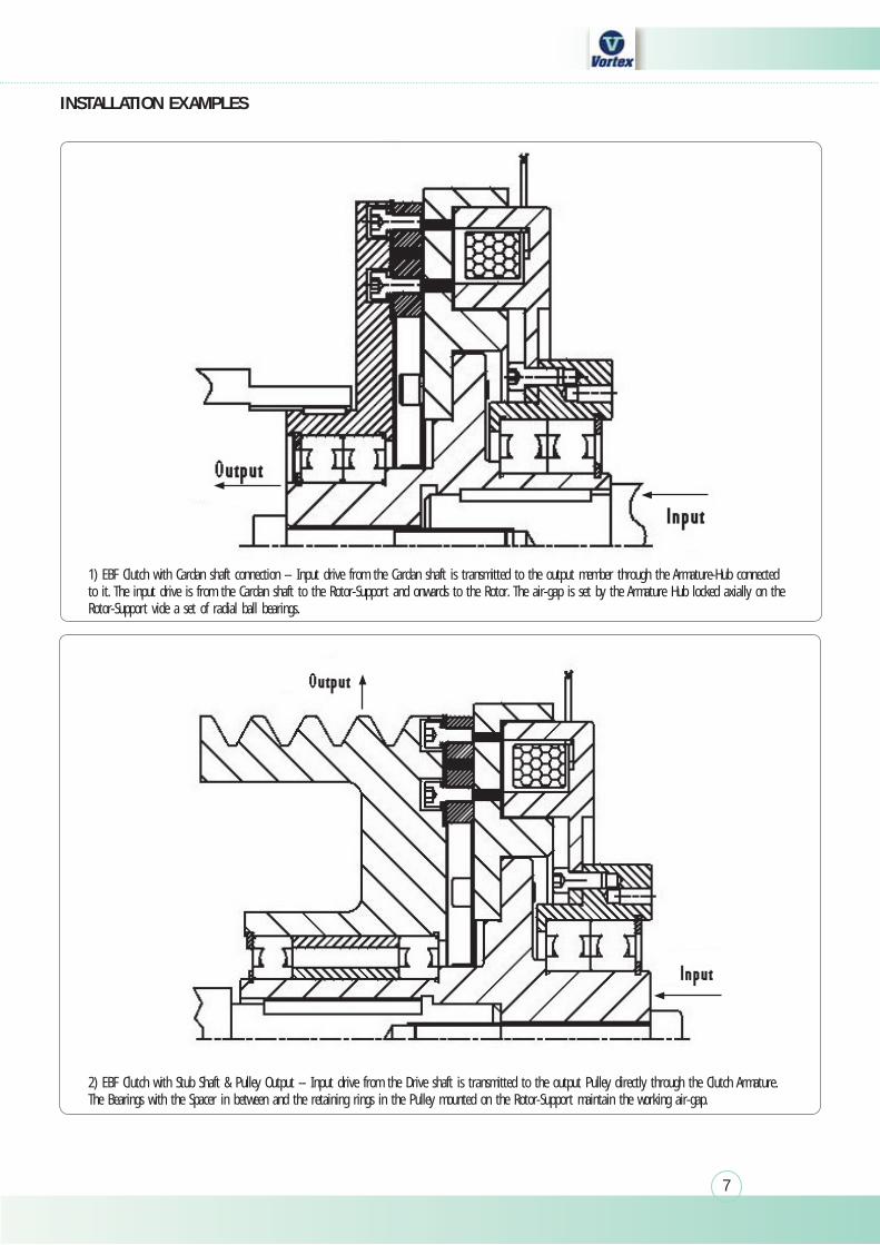
1) EBF Clutch with Cardan shaft connection -- Input drive from the Cardan shaft is transmitted to the output member through the Armature-Hub connected to it. The input drive is from the Cardan shaft to the Rotor-Support and onwards to the Rotor. The air-gap is set by the Armature Hub locked axially on the Rotor-Support vide a set of radial ball bearings.
2) EBF Clutch with Stub Shaft & Pulley Output -- Input drive from the Drive shaft is transmitted to the output Pulley directly through the Clutch Armature. The Bearings with the Spacer in between and the retaining rings in the Pulley mounted on the Rotor-Support maintain the working air-gap.
INSTALLATION EXAMPLES
8
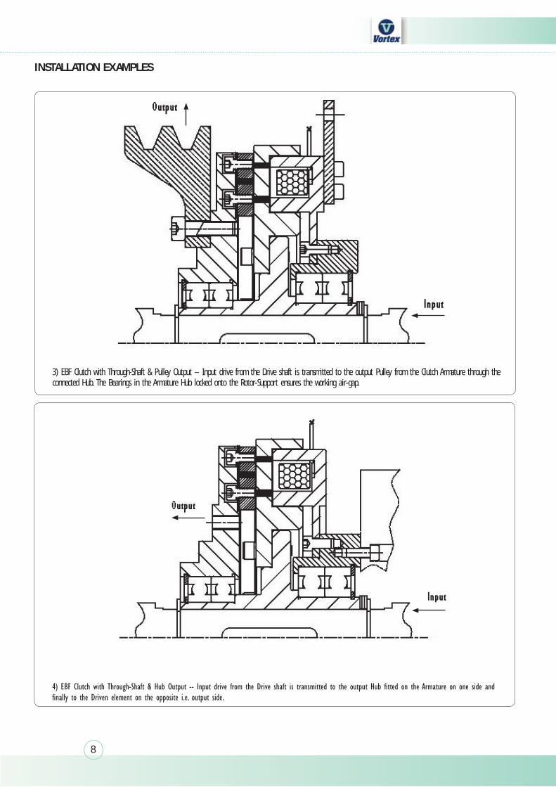
3) EBF Clutch with Through-Shaft & Pulley Output -- Input drive from the Drive shaft is transmitted to the output Pulley from the Clutch Armature through the connected Hub. The Bearings in the Armature Hub locked onto the Rotor-Support ensures the working air-gap.
INSTALLATION EXAMPLES
9
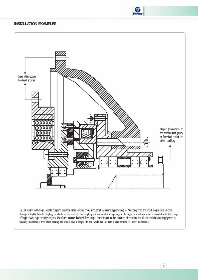
5) EBF Clutch with High Flexible Coupling used for diesel engine drives (industrial & marine applications) – Mounting onto the input engine side is done
of high power, high capacity engines. The Clutch ensures backlash-free torque transmission in the direction of rotation. The clutch and the coupling system is
INSTALLATION EXAMPLES
Output (Connection to the cardon shaft, pulley or free shaft end of the driven auxiliary
Input (Connection to diesel engine)
10
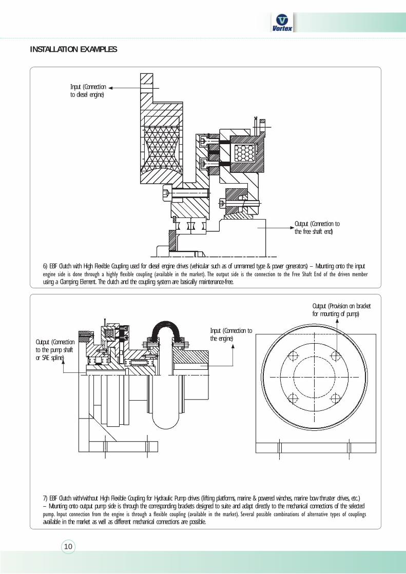
6) EBF Clutch with High Flexible Coupling used for diesel engine drives (vehicular such as of unmanned type & power generators) – Mounting onto the input
using a Clamping Element. The clutch and the coupling system are basically maintenance-free.
INSTALLATION EXAMPLES
7) EBF Clutch with/without High Flexible Coupling for Hydraulic Pump drives (lifting platforms, marine & powered winches, marine bow thruster drives, etc.) – Mounting onto output pump side is through the corresponding brackets designed to suite and adapt directly to the mechanical connections of the selected
available in the market as well as different mechanical connections are possible.
Input (Connection to diesel engine)
Output (Connection to the free shaft end)
Output (Connectionto the pump shaft or SAE spline)
Input (Connection to the engine)
Output (Provision on bracket for mounting of pump)

11

India’s foremost manufacturer of a wide range of clutches & brakes
Works & Head Office:
Plot B-3, Phase-II, M.I.D.C, Manpada road, Dombivli (E),
Thane 421204, Maharashtra. INDIA
Telephone: +91-251-2871339, +91-251-6571451, +91-251-6574451
Tele-fax: +91-251-2870044
E-mail: [email protected] Website: www.vortex-clutch.com
Subject to technical change without notice. Copyright reserved.