electrolytic capacitor tests
TRANSCRIPT
Konstantinos Papastergiou
TE-EPC
25 May 2018
Electrolytic Capacitor Tests
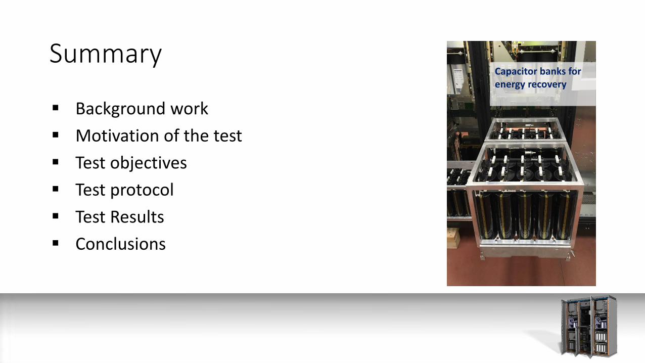
Summary
Background work
Motivation of the test
Test objectives
Test protocol
Test Results
Conclusions
Capacitor banks for energy recovery
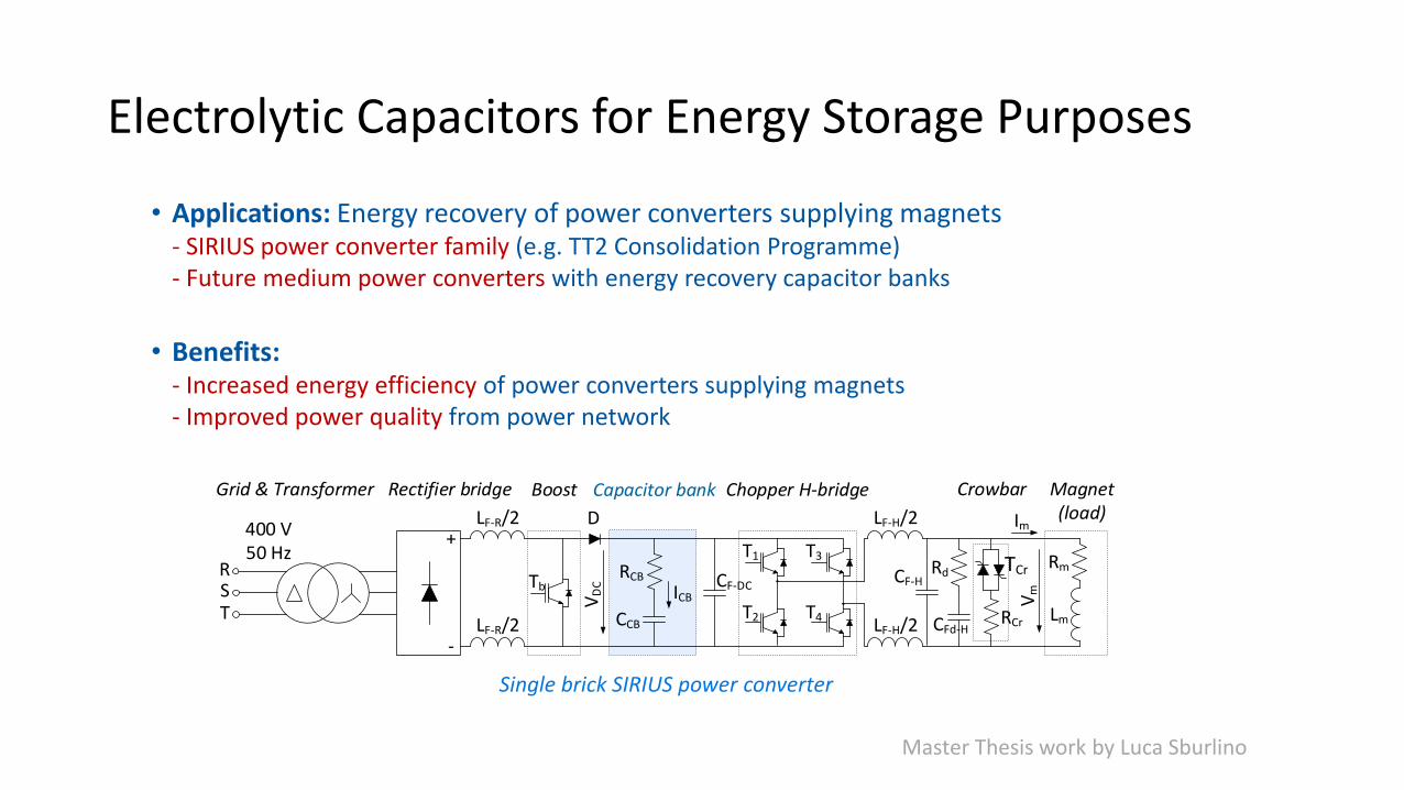
Electrolytic Capacitors for Energy Storage Purposes
• Applications: Energy recovery of power converters supplying magnets- SIRIUS power converter family (e.g. TT2 Consolidation Programme)- Future medium power converters with energy recovery capacitor banks
• Benefits:- Increased energy efficiency of power converters supplying magnets- Improved power quality from power network
LF-R/2
LF-R/2
+
-
Rectifier bridge
RCB
CCB
Capacitor bank
VD
C CF-DC
400 V50 Hz
Grid & Transformer
T1
T2
T3
T4
Chopper H-bridge
LF-H/2
LF-H/2
RST
Boost
D
Tb ICB
CF-H
CFd-H
RdRm
Lm
Magnet(load)
Vm
Im
RCr
TCr
Crowbar
Single brick SIRIUS power converter
Master Thesis work by Luca Sburlino
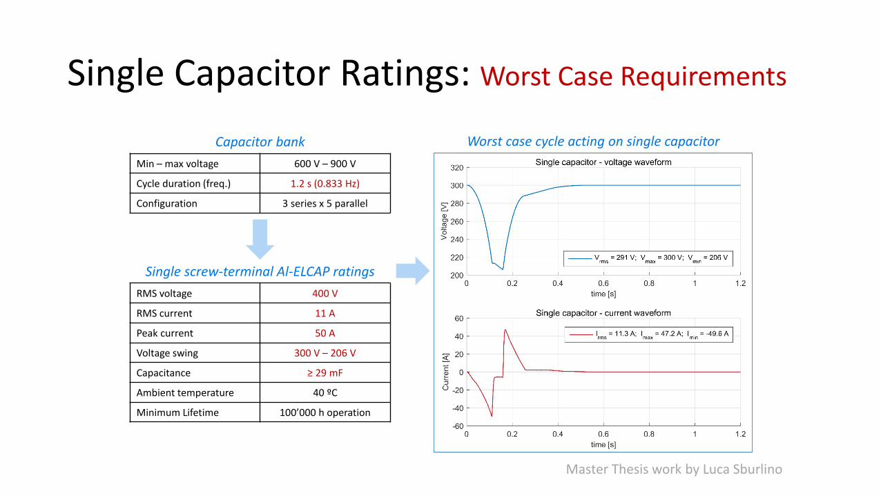
Single Capacitor Ratings: Worst Case Requirements
Capacitor bank
Min – max voltage 600 V – 900 V
Cycle duration (freq.) 1.2 s (0.833 Hz)
Configuration 3 series x 5 parallel
Single screw-terminal Al-ELCAP ratings
RMS voltage 400 V
RMS current 11 A
Peak current 50 A
Voltage swing 300 V – 206 V
Capacitance ≥ 29 mF
Ambient temperature 40 ºC
Minimum Lifetime 100’000 h operation
Worst case cycle acting on single capacitor
Master Thesis work by Luca Sburlino
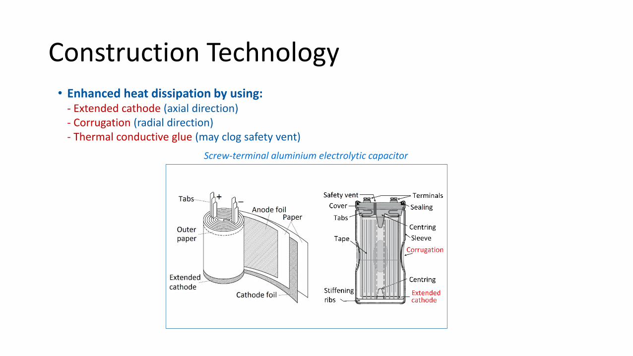
Construction Technology• Enhanced heat dissipation by using:
- Extended cathode (axial direction)- Corrugation (radial direction)- Thermal conductive glue (may clog safety vent)
Screw-terminal aluminium electrolytic capacitor
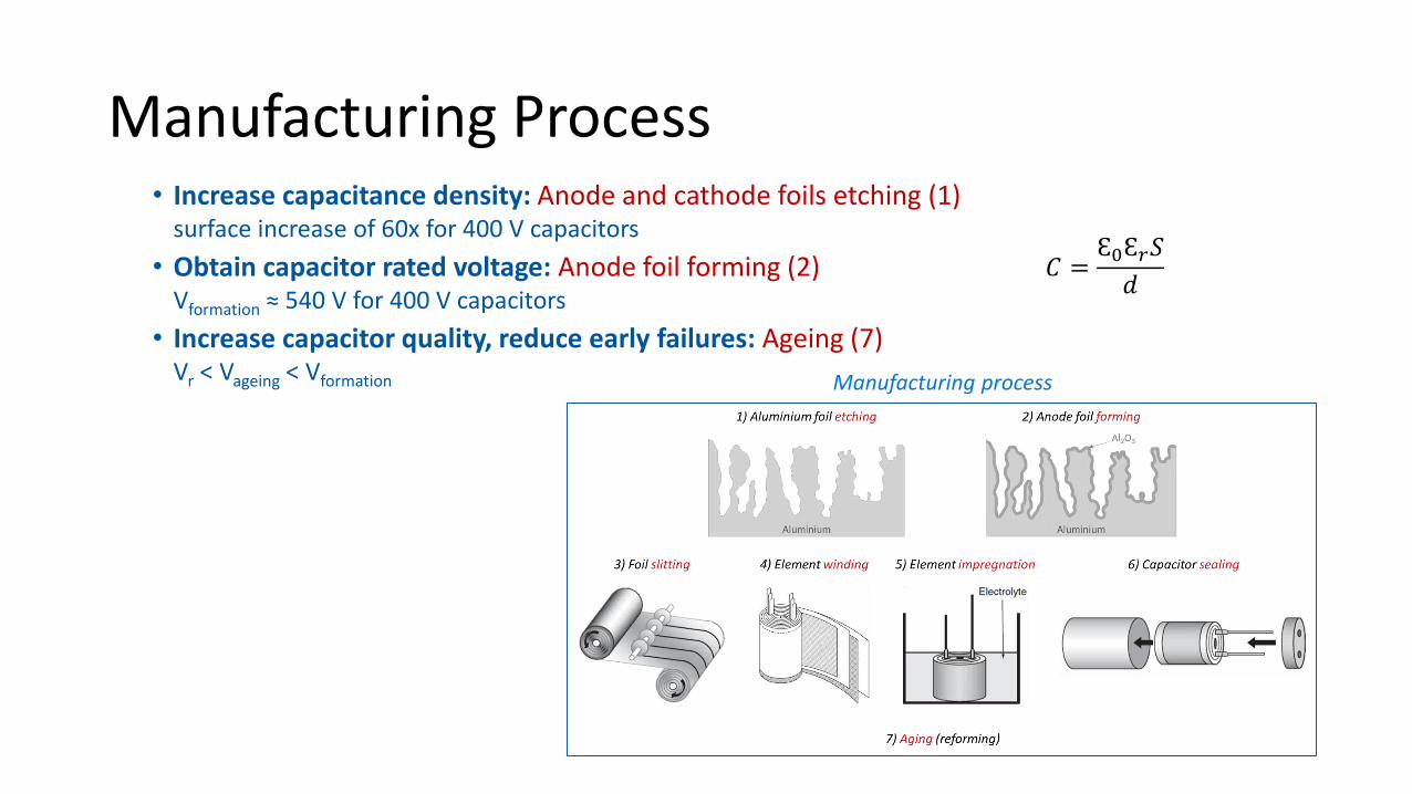
Manufacturing Process• Increase capacitance density: Anode and cathode foils etching (1)
surface increase of 60x for 400 V capacitors
• Obtain capacitor rated voltage: Anode foil forming (2)Vformation ≈ 540 V for 400 V capacitors
• Increase capacitor quality, reduce early failures: Ageing (7)Vr < Vageing < Vformation
𝐶 =Ɛ0Ɛ𝑟𝑆
𝑑
Manufacturing process
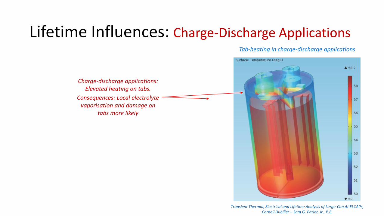
Lifetime Influences: Charge-Discharge ApplicationsTab-heating in charge-discharge applications
Charge-discharge applications:Elevated heating on tabs.
Consequences: Local electrolyte vaporisation and damage on
tabs more likely
Transient Thermal, Electrical and Lifetime Analysis of Large-Can Al-ELCAPs,Cornell Dubilier – Sam G. Parler, Jr., P.E.
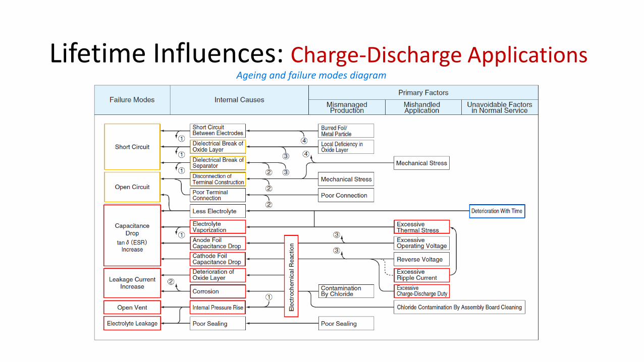
Lifetime Influences: Charge-Discharge ApplicationsAgeing and failure modes diagram
Motivation for the Tests by the manufacturer
Previous experience with capacitive energy storage shows the need to understand the failure mechanism of capacitors.
To have enough input in order to decide compensatory safety measures Visualisation of the cabinet (video) during the test
Visualisation of the vapour release from the cabinet (video) during the test
Visualisation of the test area (video), to assess the potential projection of debris
Measurement of the voltage/current during the test
Measurement of the sound pressure at 1 m from the cabinet
Photos of the cabinet (exterior+interior) after the test
Detailed photos of the capacitor bank after the test
Qualitative assesmnet of impact to the floor.
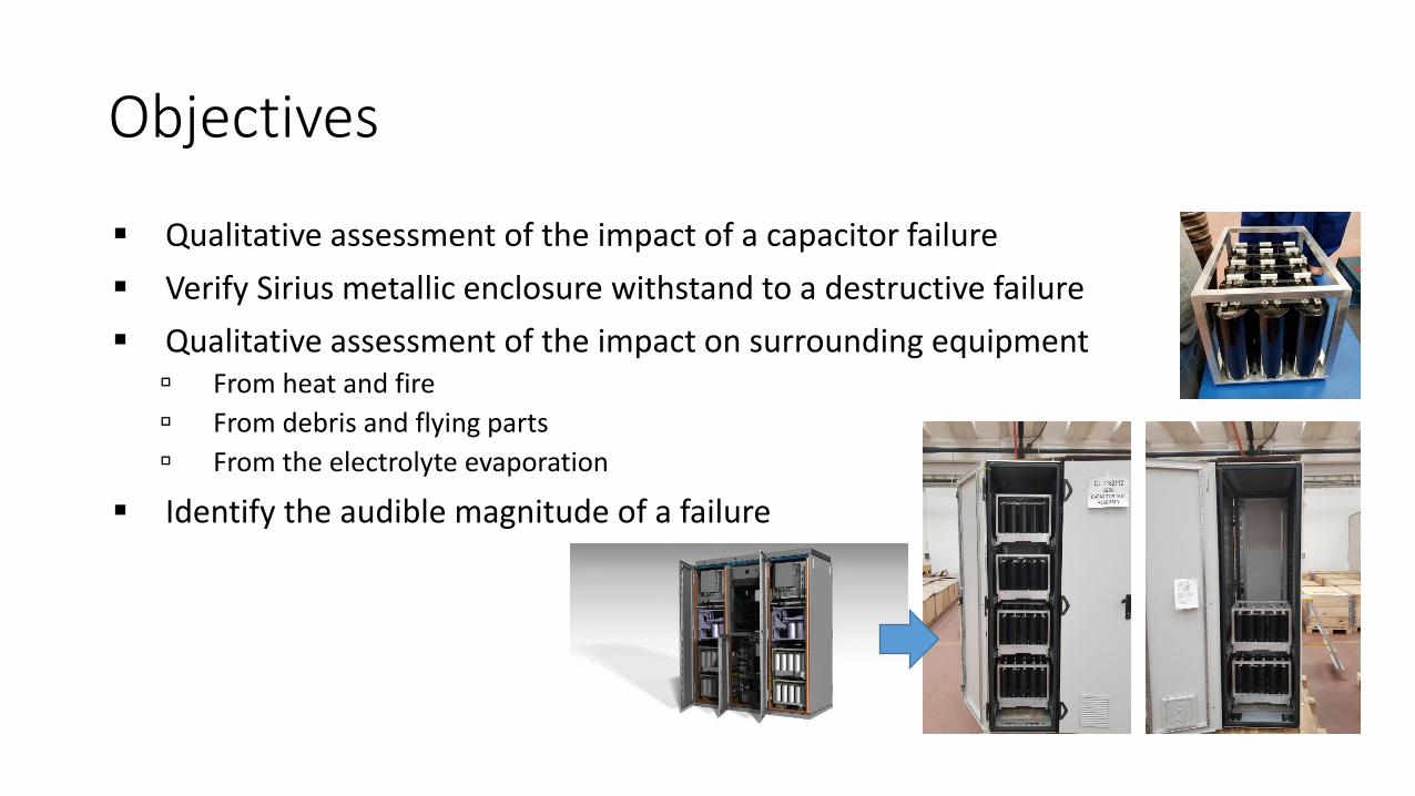
Objectives
Qualitative assessment of the impact of a capacitor failure
Verify Sirius metallic enclosure withstand to a destructive failure
Qualitative assessment of the impact on surrounding equipment From heat and fire
From debris and flying parts
From the electrolyte evaporation
Identify the audible magnitude of a failure
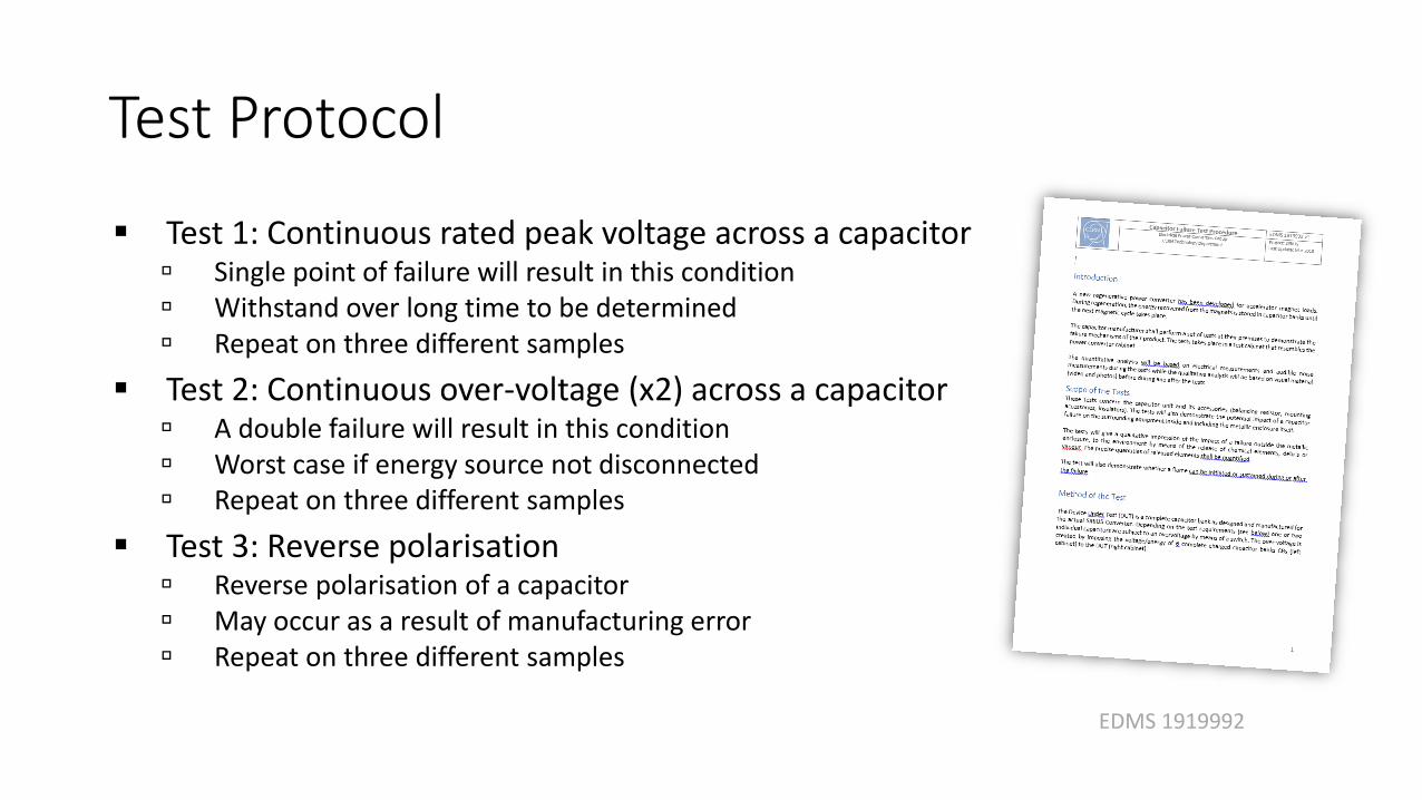
Test Protocol
Test 1: Continuous rated peak voltage across a capacitor Single point of failure will result in this condition Withstand over long time to be determined Repeat on three different samples
Test 2: Continuous over-voltage (x2) across a capacitor A double failure will result in this condition Worst case if energy source not disconnected Repeat on three different samples
Test 3: Reverse polarisation Reverse polarisation of a capacitor May occur as a result of manufacturing error Repeat on three different samples
EDMS 1919992
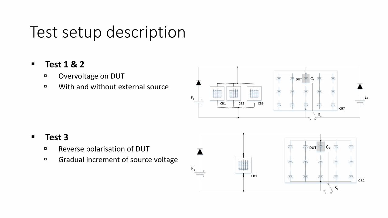
Test setup description
Test 1 & 2 Overvoltage on DUT
With and without external source
S1a b
CXDUT
E1
CB1
E2
CB7
CB6CB2
S1a b
CXDUT
E1
CB1CB2
Test 3 Reverse polarisation of DUT
Gradual increment of source voltage
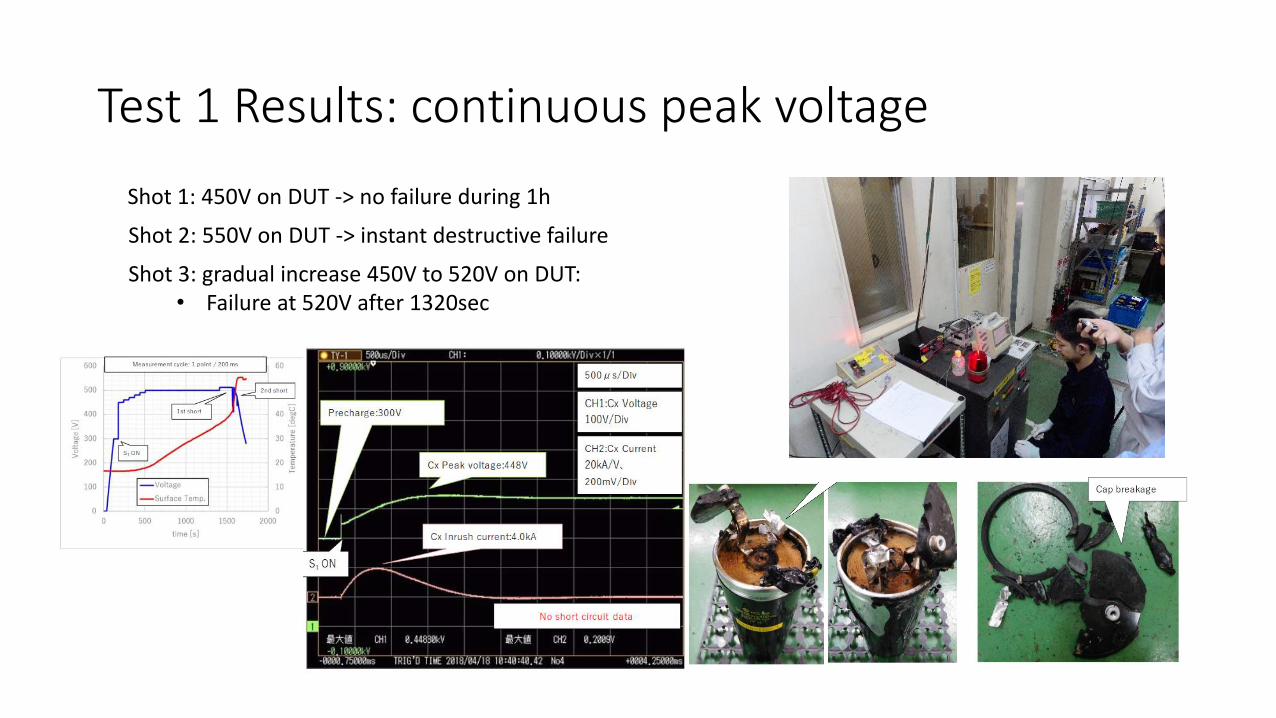
Test 1 Results: continuous peak voltage
Shot 1: 450V on DUT -> no failure during 1h
Shot 2: 550V on DUT -> instant destructive failure
Shot 3: gradual increase 450V to 520V on DUT:• Failure at 520V after 1320sec
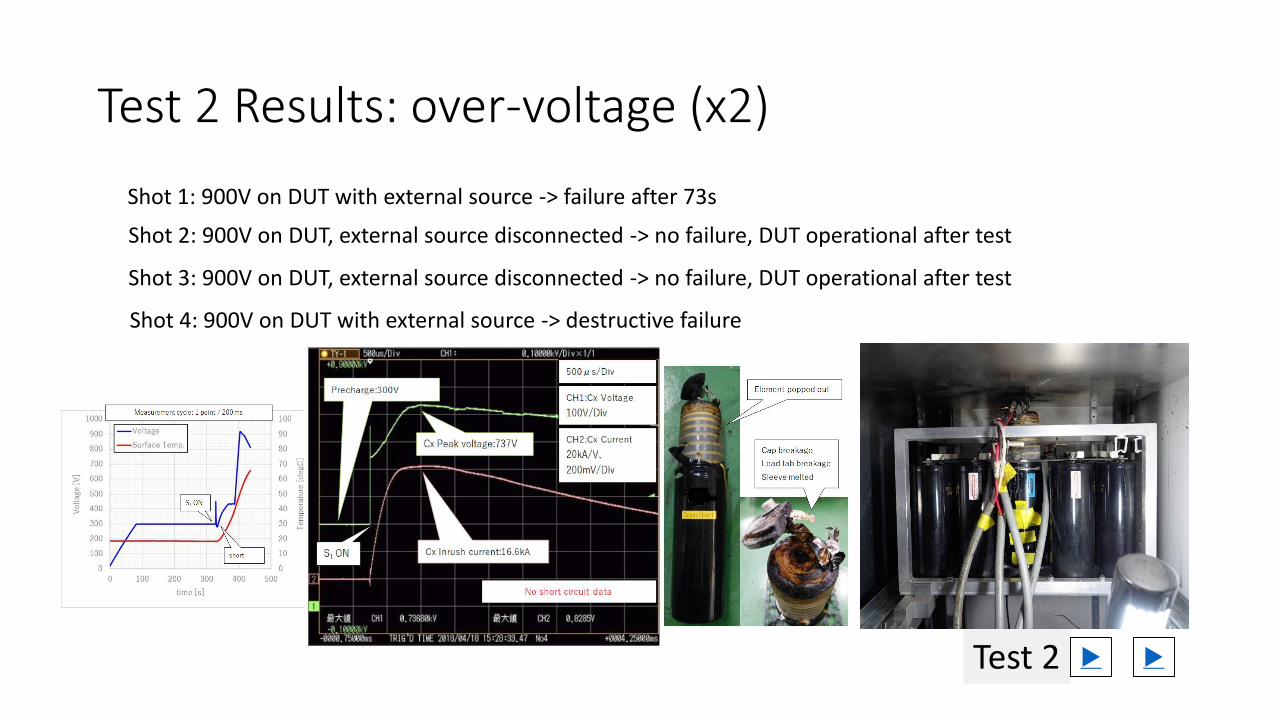
Test 2 Results: over-voltage (x2)
Test 2
Shot 1: 900V on DUT with external source -> failure after 73s
Shot 2: 900V on DUT, external source disconnected -> no failure, DUT operational after test
Shot 3: 900V on DUT, external source disconnected -> no failure, DUT operational after test
Shot 4: 900V on DUT with external source -> destructive failure
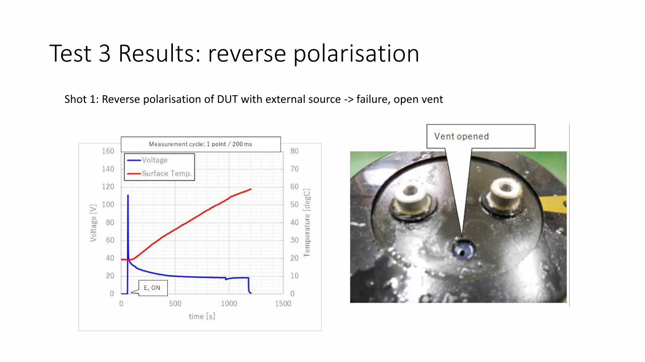
Test 3 Results: reverse polarisation
Shot 1: Reverse polarisation of DUT with external source -> failure, open vent
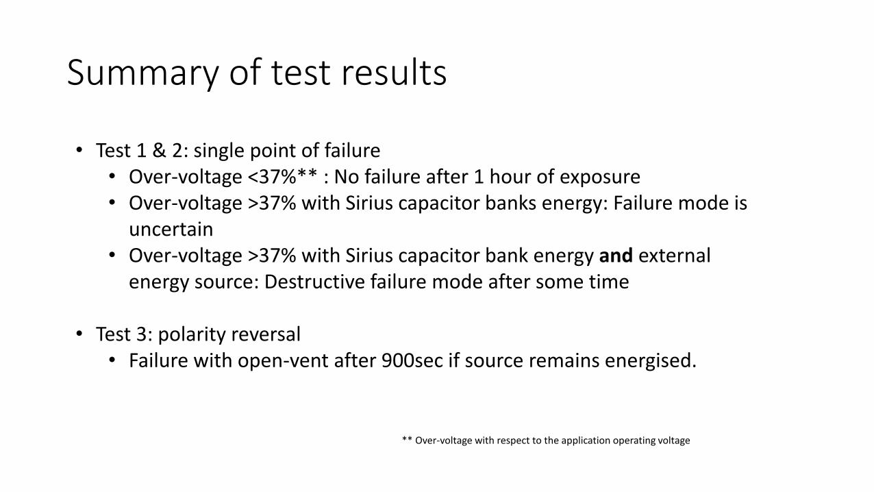
Summary of test results
• Test 1 & 2: single point of failure• Over-voltage <37%** : No failure after 1 hour of exposure• Over-voltage >37% with Sirius capacitor banks energy: Failure mode is
uncertain • Over-voltage >37% with Sirius capacitor bank energy and external
energy source: Destructive failure mode after some time
• Test 3: polarity reversal• Failure with open-vent after 900sec if source remains energised.
** Over-voltage with respect to the application operating voltage
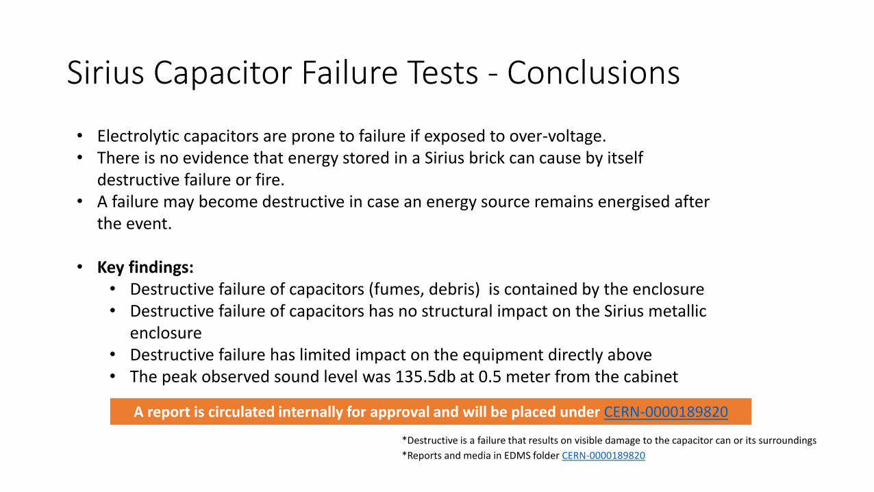
Sirius Capacitor Failure Tests - Conclusions
• Electrolytic capacitors are prone to failure if exposed to over-voltage.• There is no evidence that energy stored in a Sirius brick can cause by itself
destructive failure or fire.• A failure may become destructive in case an energy source remains energised after
the event.
• Key findings:• Destructive failure of capacitors (fumes, debris) is contained by the enclosure • Destructive failure of capacitors has no structural impact on the Sirius metallic
enclosure• Destructive failure has limited impact on the equipment directly above• The peak observed sound level was 135.5db at 0.5 meter from the cabinet
*Destructive is a failure that results on visible damage to the capacitor can or its surroundings
*Reports and media in EDMS folder CERN-0000189820
A report is circulated internally for approval and will be placed under CERN-0000189820