electrical safety & arc flash protection - idc-online.com · 2019-02-04 · electrical safety...
TRANSCRIPT
157
Electrical Safety & Arc Flash ProtectionIntroductionThere is a great deal of activity in the electrical industry concerningelectrical safety. The focus is on the two greatest electrical hazards toworkers: shock and arc flash. In recent years significant knowledgehas been gained through testing and analysis concerning arc flashhazards and how to contend with this type of hazard. This hazardexists when a worker is working on or near exposed electric conduc-tors or circuit parts that have not been placed in a safe work condition.If an arcing fault occurs, the tremendous energy released in a fractionof a second can result in serious injury or death. However, there is agreat challenge in getting the message to the populace of the electri-cal industry so that safer system designs and safer work proceduresand behaviors result. Workers continue to sustain life altering injuriesor death. NFPA 70E “Standard for Electrical Safety Requirements forEmployee Workplaces” is the foremost consensus standard on elec-trical safety. As of this writing, the current version is NFPA 70E – 2000and NFPA 70E – 2003 is in development. Each succeeding revisionadvances the safety requirements.
Why is there an NFPA 70E? In 1976 a new electrical standardsdevelopment committee was formed to assist the OccupationalSafety and Health Administration (OSHA) in preparing electricalsafety standards. This committee on Electrical Safety RequirementsFor Employee Workplaces, NFPA 70E, was needed for a number ofreasons, including: (1) the NEC® is an installation standard whileOSHA also addresses employee safety in the workplace, (2) not allsections in the NEC® relate to worker safety and these are thereforeof little value to OSHAs focus and needs, (3) many safety relatedwork and maintenance practices are not covered, or not adequate-ly covered, in the NEC® and (4) a national consensus standard onelectrical safety for workers did not exist, but was needed – an easyto understand document that addresses worker electrical safety.The first edition was published in 1979.
The current NFPA 70E - 2000 consists of four parts;Part I Installation Safety RequirementsPart II Safety-Related Work PracticesPart III Safety-Related Maintenance RequirementsPart IV Safety Requirements for Special Equipment
Only Work On Equipment That Is In A Safe Work ConditionThe rule for the industry and the law is “don’t work it hot”. PerOSHA 1910.333(a)(1) and NFPA 70E–2000 Part II 2-1.1.1, workersshould not work on or near exposed live parts except for twodemonstrable reasons:1. deenergizing introduces additional or increased hazards (such
as cutting ventilation to a hazardous location) or 2. infeasible due to equipment design or operational limitations
(such as when voltage testing is required for diagnostics). Financial considerations are not an adequate reason to work on or nearenergized circuits. To violate these regulations and practices is a vio-lation of federal law, which is punishable by fine and/or imprisonment.
Note: deenergized electrical parts are considered as energized untilall steps of the lockout/tagout procedure are successfully completed[OSHA 1910.333(b)] and the equipment has been successfully putin a “safe work condition” (NFPA 70E). Voltage testing of each con-ductor, which is a necessary step while completing the lockout/tagout procedure (putting the equipment in a safe work condition), isconsidered as working on energized parts per OSHA 1910.333(b)and NFPA 70E – 2000 Part II 5-1.
Therefore, adequate personal protective equipment is always requiredduring the tests to verify the absence of voltage after the circuits aredeenergized and properly locked out/tagged out. Adequate PPE mayalso be required during load interruption and during visual inspectionthat verifies that all disconnecting devices are open.
So no matter how well a worker follows safe work practices, therewill always be a risk associated with electrical equipment – even
when putting equipment in a “safe work condition”. And there arethose occasions where it is necessary to work on energized equip-ment such as when a problem can not be uncovered by troubleshooting the equipment in a deenergized state.
What Can Be Done To Lessen the Risk?There are a multitude of things that can be implemented to increaseelectrical safety, from design aspects and upgrading systems, to train-ing, implementing safe work practices and utilizing personal protectiveequipment (PPE). Not all of these topics can be covered in this section.The focus of this section will mainly concern some overcurrent protec-tion aspects related to electrical safety. For some other related electricalsafety topics, read the Bussmann® Safety BASICsTM Handbook andvisit the Safety BASICsTM webpage at www.bussmann.com.
Shock ProtectionThere are three shock approach boundaries required to be observedin NFPA 70E - 2000 Part II Table 2-1.3.4; these shock approach bound-aries are dependent upon the system voltage. The significance ofthese boundaries for workers and their actions while within the bound-aries can be found in NFPA 70E or the Bussmann® Safety BASICsTM
Handbook. See Figure 2 for a graphic depiction of the three shockapproach boundaries with the flash protection boundary (following thesection on Flash Hazard Assessment). For hazard analysis and workerprotection, it is important to observe the shock approach boundariestogether with the flash protection boundary (which is covered in para-graphs ahead).
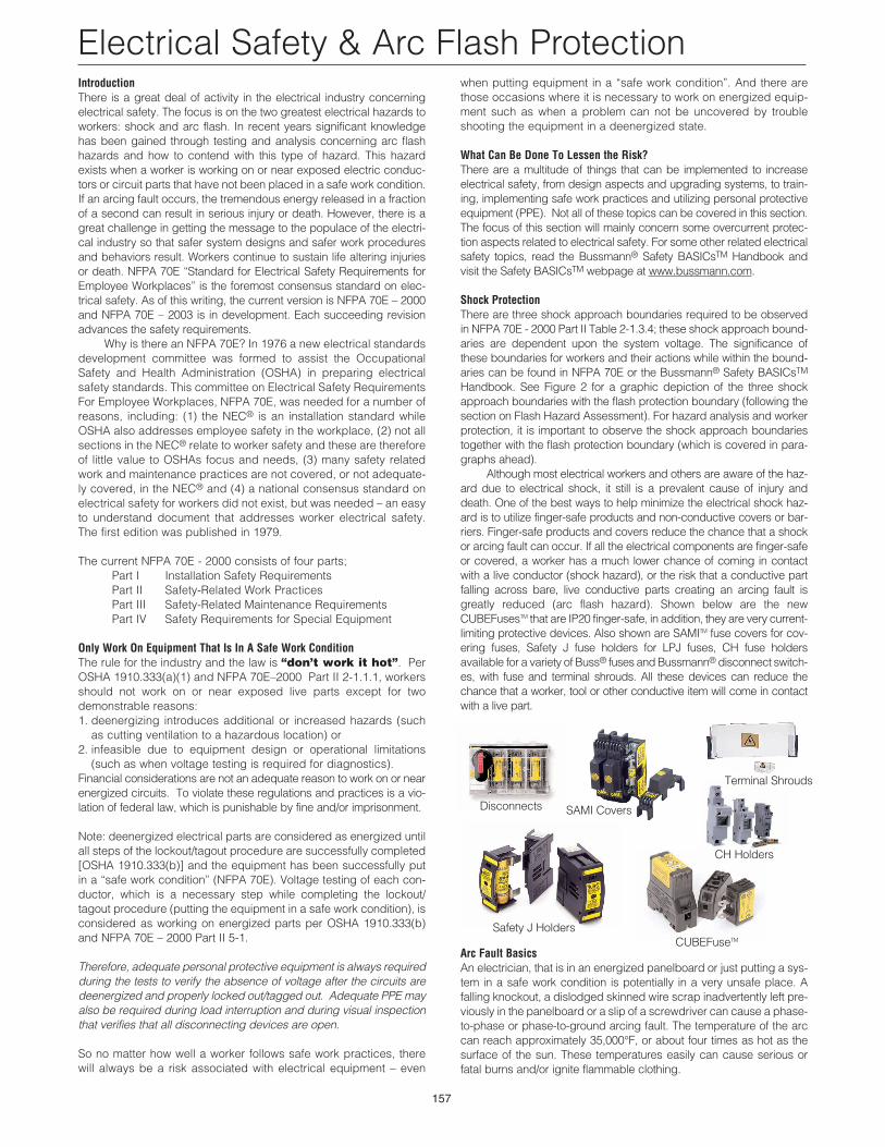
Although most electrical workers and others are aware of the haz-ard due to electrical shock, it still is a prevalent cause of injury anddeath. One of the best ways to help minimize the electrical shock haz-ard is to utilize finger-safe products and non-conductive covers or bar-riers. Finger-safe products and covers reduce the chance that a shockor arcing fault can occur. If all the electrical components are finger-safeor covered, a worker has a much lower chance of coming in contactwith a live conductor (shock hazard), or the risk that a conductive partfalling across bare, live conductive parts creating an arcing fault isgreatly reduced (arc flash hazard). Shown below are the newCUBEFusesTM that are IP20 finger-safe, in addition, they are very current-limiting protective devices. Also shown are SAMITM fuse covers for cov-ering fuses, Safety J fuse holders for LPJ fuses, CH fuse holdersavailable for a variety of Buss® fuses and Bussmann® disconnect switch-es, with fuse and terminal shrouds. All these devices can reduce thechance that a worker, tool or other conductive item will come in contactwith a live part.
Arc Fault BasicsAn electrician, that is in an energized panelboard or just putting a sys-tem in a safe work condition is potentially in a very unsafe place. Afalling knockout, a dislodged skinned wire scrap inadvertently left pre-viously in the panelboard or a slip of a screwdriver can cause a phase-to-phase or phase-to-ground arcing fault. The temperature of the arccan reach approximately 35,000°F, or about four times as hot as thesurface of the sun. These temperatures easily can cause serious orfatal burns and/or ignite flammable clothing.
Disconnects SAMI Covers
Safety J HoldersCUBEFuseTM
CH Holders
Terminal Shrouds
Electrical Safety & Arc Flash Protection
158
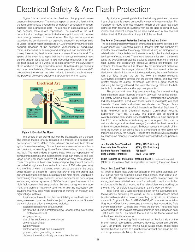
Figure 1 is a model of an arc fault and the physical conse-quences that can occur. The unique aspect of an arcing fault is thatthe fault current flows through the air between conductors or a con-ductor(s) and a grounded part. The arc has an associated arc volt-age because there is arc impedance. The product of the faultcurrent and arc voltage concentrated at one point, results in tremen-dous energy released in several forms. The high arc temperaturevaporizes the conductors in an explosive change in state from solidto vapor (copper vapor expands to 67,000 times the volume of solidcopper). Because of the expansive vaporization of conductivemetal, a line-to-line or line-to-ground arcing fault can escalate into athree phase arcing fault in less than a thousandth of a second. Thespeed of the event is so rapid that the human system can not reactquickly enough for a worker to take corrective measures. If an arc-ing fault occurs while a worker is in close proximity, the survivabilityof the worker is mostly dependent upon (1) system design aspects,such as characteristics of the overcurrent protective devices and (2)precautions the worker has taken prior to the event, such as wear-ing personal protective equipment appropriate for the hazard.
The effects of an arcing fault can be devastating on a person.The intense thermal energy released in a fraction of a second cancause severe burns. Molten metal is blown out and can burn skin orignite flammable clothing. One of the major causes of serious burnsand deaths to workers is ignition of flammable clothing due to an arc-ing fault. The tremendous pressure blast from the vaporization ofconducting materials and superheating of air can fracture ribs, col-lapse lungs and knock workers off ladders or blow them across aroom. The pressure blast can cause shrapnel (equipment parts) tobe hurled at high velocity (can be in excess of 700 miles per hour).And the time in which the arcing event runs its course can be only asmall fraction of a second. Testing has proven that the arcing faultcurrent magnitude and time duration are the most critical variables indetermining the energy released. Serious accidents are occurring atan alarming rate on systems of 600V or less, in part because of thehigh fault currents that are possible. But also, designers, manage-ment and workers mistakenly tend not to take the necessary pre-cautions that they take when designing or working on medium andhigh voltage systems.
It is important to note that the predictability of arc faults and theenergy released by an arc fault is subject to great variance. Some ofthe variables that affect the outcome include:
available bolted short-circuit currentthe time the fault is permitted to flow (speed of the overcurrent
protective device)arc gap spacingsize of the enclosure or no enclosurepower factor of faultsystem voltagewhether arcing fault can sustain itselftype of system grounding schemedistance the worker’s body parts are from the arc
Electrical Arc
Copper Vapor:Solid to VaporExpands by67,000 times
Intense Light
Hot Air-Rapid Expansion
35,00035,000 °F
Pressure Waves
Sound Waves
Molten Metal
Shrapnel
Typically, engineering data that the industry provides concern-ing arcing faults is based on specific values of these variables. Forinstance, for 600V and less systems, much of the data has beengathered from testing on systems with an arc gap spacing of 1.25inches and incident energy (to be discussed later in this section)determined at 18 inches from the point of the arc fault.
The Role of Overcurrent Protective Devices In Electrical SafetyThe selection and performance of overcurrent protective devices playa significant role in electrical safety. Extensive tests and analysis byindustry has shown that the energy released during an arcing fault isrelated to two characteristics of the overcurrent protective device pro-tecting the affected circuit. These two characteristics are 1) the time ittakes the overcurrent protective device to open and 2) the amount offault current the overcurrent protective device lets-through. Forinstance, the faster the fault is cleared by the overcurrent protectivedevice, the lower the energy released. If the overcurrent protectivedevice can also limit the current, thereby reducing the actual fault cur-rent that flows through the arc, the lower the energy released.Overcurrent protective devices that are current-limiting, and thus maygreatly reduce the current let-through, can have a great affect onreducing the energy released. The lower the energy released the bet-ter for both worker safety and equipment protection.
The photos and recording sensor readings from actual arcingfault tests (next page) illustrate this point very well. An ad hoc electri-cal safety working group, within the IEEE Petroleum and ChemicalIndustry Committee, conducted these tests to investigate arc faulthazards. These tests and others are detailed in “Staged TestsIncrease Awareness of Arc-Fault Hazards in Electrical Equipment”,IEEE Petroleum and Chemical Industry Conference Record,September, 1997, pp. 313-322. This paper can be found atwww.bussmann.com under Services/Safety BASICs. One finding ofthis IEEE paper is that current-limiting overcurrent protective devicesreduce damage and arc-fault energy (provided the fault current iswithin the current-limiting range). To better assess the benefit of lim-iting the current of an arcing fault, it is important to note some keythresholds of injury for humans. Results of these tests were recordedby sensors on mannequins and can be compared to these parame-ters:
Just Curable Burn Threshold: 80°C / 175°F (0.1 sec)Incurable Burn Threshold: 96°C / 205°F (0.1 sec)Eardrum Rupture Threshold: 720 lbs/ft2Lung Damage Threshold: 1728 - 2160 lbs/ft2
OSHA Required Ear Protection Threshold: 85 db (for sustained time period)
(Note: an increase of 3 db is equivalent to doubling the sound level.)
Test 4, Test 3 and Test 1: GeneralAll three of these tests were conducted on the same electrical cir-cuit set-up with an available bolted three phase, short-circuit cur-rent of 22,600 symmetrical rms amperes at 480V. In each case, anarcing fault was initiated in a size 1 combination motor controllerenclosure with the door open, as if an electrician were working onthe unit “live” or before it was placed in a safe work condition.
Test 4 and Test 3 were identical except for the overcurrent pro-tective device protecting the circuit. In Test 4, a 640 ampere circuitbreaker with a short-time delay is protecting the circuit; the circuit wascleared in 6 cycles. In Test 3, KRP-C-601SP, 601 ampere, current-lim-iting fuses (Class L) are protecting the circuit; they opened the faultcurrent in less than 1/2 cycle and limited the current. The arcing faultwas initiated on the line side of the motor branch circuit device in bothTest 4 and Test 3. This means the fault is on the feeder circuit butwithin the controller enclosure.
In Test 1, the arcing fault is initiated on the load side of thebranch circuit overcurrent protective devices, which are LPS-RK30SP, 30 ampere, current-limiting fuses (Class RK1). These fuseslimited this fault current to a much lower amount and clear the cir-cuit in approximately 1/4 cycle or less.
Figure 1. Electrical Arc Model
1
159
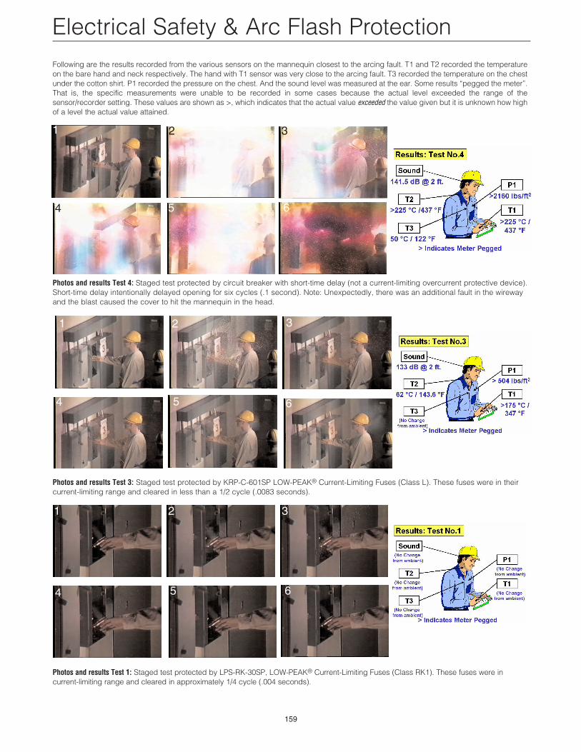
Electrical Safety & Arc Flash ProtectionFollowing are the results recorded from the various sensors on the mannequin closest to the arcing fault. T1 and T2 recorded the temperatureon the bare hand and neck respectively. The hand with T1 sensor was very close to the arcing fault. T3 recorded the temperature on the chestunder the cotton shirt. P1 recorded the pressure on the chest. And the sound level was measured at the ear. Some results “pegged the meter”.That is, the specific measurements were unable to be recorded in some cases because the actual level exceeded the range of thesensor/recorder setting. These values are shown as >, which indicates that the actual value exceeded the value given but it is unknown how highof a level the actual value attained.
Photos and results Test 4: Staged test protected by circuit breaker with short-time delay (not a current-limiting overcurrent protective device).Short-time delay intentionally delayed opening for six cycles (.1 second). Note: Unexpectedly, there was an additional fault in the wirewayand the blast caused the cover to hit the mannequin in the head.
Photos and results Test 3: Staged test protected by KRP-C-601SP LOW-PEAK® Current-Limiting Fuses (Class L). These fuses were in theircurrent-limiting range and cleared in less than a 1/2 cycle (.0083 seconds).
Photos and results Test 1: Staged test protected by LPS-RK-30SP, LOW-PEAK® Current-Limiting Fuses (Class RK1). These fuses were in current-limiting range and cleared in approximately 1/4 cycle (.004 seconds).
2 3
4 5 6
1 2 3
4 5 6
1 2 3
4 5 6
160
A couple of conclusions can be drawn from this testing. (1) Arcing faults can release tremendous amounts of energy in
many forms in a very short period of time. Look at all the mea-sured values compared to key thresholds of injury for humansgiven in a previous paragraph. Test 4 was protected by a 640A, non-current limiting device that opened in 6 cycles or .1 sec-ond.
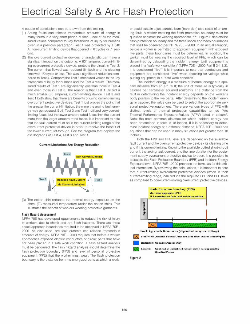
(2) The overcurrent protective devices’ characteristic can have asignificant impact on the outcome. A 601 ampere, current-limit-ing overcurrent protective device, protects the circuit in Test 3.The current that flowed was reduced (limited) and the clearingtime was 1/2 cycle or less. This was a significant reduction com-pared to Test 4. Compare the Test 3 measured values to the keythresholds of injury for humans and the Test 4 results. The mea-sured results of Test 1 are significantly less than those in Test 4and even those in Test 3. The reason is that Test 1 utilized amuch smaller (30 ampere), current-limiting device. Test 3 andTest 1 both show that there are benefits of using current-limitingovercurrent protective devices. Test 1 just proves the point thatthe greater the current-limitation, the more the arcing fault ener-gy may be reduced. Both Test 3 and Test 1 utilized very current-limiting fuses, but the lower ampere rated fuses limit the currentmore than the larger ampere rated fuses. It is important to notethat the fault current must be in the current-limiting range of theovercurrent protective device in order to receive the benefit ofthe lower current let-through. See the diagram that depicts theoscillographs of Test 4, Test 3 and Test 1.
(3) The cotton shirt reduced the thermal energy exposure on thechest (T3 measured temperature under the cotton shirt). Thisillustrates the benefit of workers wearing protective garments.
Flash Hazard AssessmentNFPA 70E has developed requirements to reduce the risk of injuryto workers due to shock and arc flash hazards. There are threeshock approach boundaries required to be observed in NFPA 70E -2000. As discussed, arc fault currents can release tremendousamounts of energy. NFPA 70E – 2000 requires that before a workerapproaches exposed electric conductors or circuit parts that havenot been placed in a safe work condition; a flash hazard analysismust be performed. The flash hazard analysis should determine theflash protection boundary (FPB) and level of personal protectiveequipment (PPE) that the worker must wear. The flash protectionboundary is the distance from the energized parts at which a work-
Non-Current Limiting
Test 1
Test 4
Test 3 Reduced Fault Current
via Current-Limitation
Current-Limitation: Arc-Energy ReductionCurrent-Limitation: Arc-Energy ReductionCurrent-Limitation: Arc-Energy Reduction
er could sustain a just curable burn (bare skin) as a result of an arc-ing fault. A worker entering the flash protection boundary must bequalified and must be wearing appropriate PPE. Figure 2 depicts theflash protection boundary and the three shock approach boundariesthat shall be observed per NFPA 70E - 2000. In an actual situation,before a worker is permitted to approach equipment with exposedlive parts, these boundaries must be determined. In addition, theworker must be wearing the required level of PPE, which can bedetermined by calculating the incident energy. Until equipment isplaced in a “safe work condition” (NFPA 70E – 2000 Part II 2-1.1.3),it is considered “live”. It is important to note that conductors andequipment are considered “live” when checking for voltage whileputting equipment in a “safe work condition”.
The incident energy is a measure of thermal energy at a spe-cific distance from an arc fault; the unit of measure is typically incalories per centimeter squared (cal/cm2). The distance from thefault in determining the incident energy depends on the worker’sbody position to the live parts. After determining the incident ener-gy in cal/cm2, the value can be used to select the appropriate per-sonal protective equipment. There are various types of PPE withdistinct levels of thermal protection capabilities termed “ArcThermal Performance Exposure Values (ATPV) rated in cal/cm2.Note: the most common distance for which incident energy hasbeen determined in tests is 18 inches. If it is necessary to deter-mine incident energy at a different distance, NFPA 70E - 2000 hasequations that can be used in many situations (for greater than 18inches).
Both the FPB and PPE level are dependent on the availablefault current and the overcurrent protective device - its clearing timeand if it is current-limiting. Knowing the available bolted short-circuitcurrent, the arcing fault current, and the time duration for the equip-ment supply overcurrent protective device to open, it is possible tocalculate the Flash Protection Boundary (FPB) and Incident EnergyExposure level. NFPA 70E - 2000 provides the formulas for this crit-ical information. By reviewing the calculations, it is important to notethat current-limiting overcurrent protective devices (when in theircurrent-limiting range) can reduce the required FPB and PPE levelas compared to non-current-limiting overcurrent protective devices.
Figure 2
Electrical Safety & Arc Flash Protection
161
Electrical Safety & Arc Flash Protection
Simple Method for Flash Hazard Analysis Anytime work must be done on or near energized electrical equip-ment or equipment that could become energized, a flash hazardanalysis must be completed. This flash hazard analysis includes,but is not limited to, determining:
1. the Incident Energy Exposure to select the level of PPE neededto complete the task
2. the Flash Protection Boundary to know the approach point to theequipment where PPE will be required.
Various information about the system may be needed to com-plete this analysis but the two pieces that are absolutely necessaryare:
1. the available 3Ø bolted fault current 2. the fuse or circuit breaker type and ampere rating.
Consider the following one-line diagram and then follow theexamples that take the steps needed to conduct a Flash HazardAnalysis (The following information utilizes formulas based uponIEEE Guide for Arc Flash Hazard Analysis, P1584. It is expected thatthis information will be included in the upcoming edition of NFPA70E-2003.). Be sure to read the Notes associated with each section.
Figure 3
Example 1: Flash Hazard Analysis using Bussmann® Current LimitingFuses.The following is a simple method when using certain Bussmann®
fuses; this method is based on actual data from arcing fault tests withBussmann® current-limiting fuses. Using this simple method, the firstthing that must be done is to determine the incident energy exposure.Bussmann has simplified this process when using LPS-RK-(amp)SP,LPJ-(amp)SP, LP-CC-(amp) or KRP-C-(amp)SP LOW-PEAK® fusesor JJS-(amp) TRON® fuses. In some cases the results are conserva-tive; see Note 12.
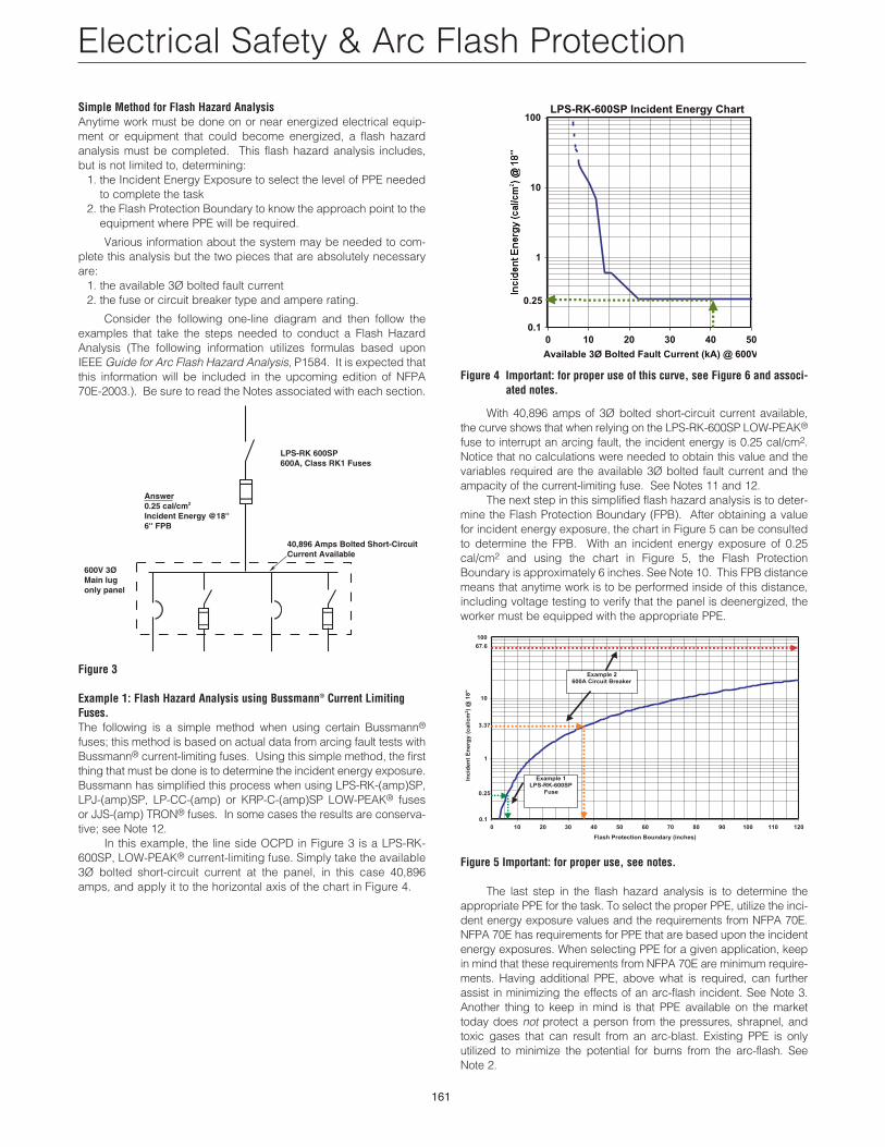
In this example, the line side OCPD in Figure 3 is a LPS-RK-600SP, LOW-PEAK® current-limiting fuse. Simply take the available3Ø bolted short-circuit current at the panel, in this case 40,896amps, and apply it to the horizontal axis of the chart in Figure 4.
600V 3ØMain lugonly panel
40,896 Amps Bolted Short-CircuitCurrent Available
LPS-RK 600SP600A, Class RK1 Fuses
Answer0.25 cal/cm2
Incident Energy @18''6'' FPB
Figure 4 Important: for proper use of this curve, see Figure 6 and associ-ated notes.
With 40,896 amps of 3Ø bolted short-circuit current available,the curve shows that when relying on the LPS-RK-600SP LOW-PEAK®
fuse to interrupt an arcing fault, the incident energy is 0.25 cal/cm2.Notice that no calculations were needed to obtain this value and thevariables required are the available 3Ø bolted fault current and theampacity of the current-limiting fuse. See Notes 11 and 12.
The next step in this simplified flash hazard analysis is to deter-mine the Flash Protection Boundary (FPB). After obtaining a valuefor incident energy exposure, the chart in Figure 5 can be consultedto determine the FPB. With an incident energy exposure of 0.25cal/cm2 and using the chart in Figure 5, the Flash ProtectionBoundary is approximately 6 inches. See Note 10. This FPB distancemeans that anytime work is to be performed inside of this distance,including voltage testing to verify that the panel is deenergized, theworker must be equipped with the appropriate PPE.
Figure 5 Important: for proper use, see notes.
The last step in the flash hazard analysis is to determine theappropriate PPE for the task. To select the proper PPE, utilize the inci-dent energy exposure values and the requirements from NFPA 70E.NFPA 70E has requirements for PPE that are based upon the incidentenergy exposures. When selecting PPE for a given application, keepin mind that these requirements from NFPA 70E are minimum require-ments. Having additional PPE, above what is required, can furtherassist in minimizing the effects of an arc-flash incident. See Note 3.Another thing to keep in mind is that PPE available on the markettoday does not protect a person from the pressures, shrapnel, andtoxic gases that can result from an arc-blast. Existing PPE is only utilized to minimize the potential for burns from the arc-flash. See Note 2.
0.1
1
10
100
0 10 20 30 40 50 60 70 80 90 100 110 120
Flash Protection Boundary (inches)
Example 1LPS-RK-600SP
Fuse
Example 2600A Circuit Breaker
0.25
3.37
67.6
Inc
ide
nt
En
erg
y (
ca
l/c
m2)
@ 1
8"
LPS-RK-600SP Incident Energy Chart
0.1
1
10
100
0 10 20 30 40 50
Available 3Ø Bolted Fault Current (kA) @ 600V
0.25
162
Electrical Safety & Arc Flash Protection
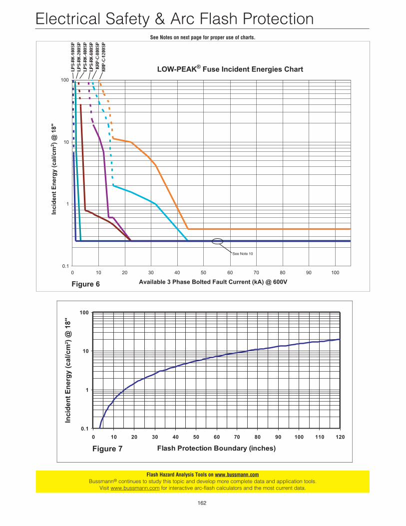
LOW-PEAK® Fuse Incident Energies Chart
0.1
1
10
100
0 10 20 30 40 50 60 70 80 90 100
Available 3 Phase Bolted Fault Current (kA) @ 600V
Inci
den
t E
ner
gy
(cal
/cm
2 ) @
18"
Figure 6
See Note 10
0.1
1
10
100
0 10 20 30 40 50 60 70 80 90 100 110 120
Flash Protection Boundary (inches)
Inci
den
t E
ner
gy
(cal
/cm
2 ) @
18"
Figure 7
Flash Hazard Analysis Tools on www.bussmann.comBussmann® continues to study this topic and develop more complete data and application tools.
Visit www.bussmann.com for interactive arc-flash calculators and the most current data.
See Notes on next page for proper use of charts.
163
Electrical Safety & Arc Flash ProtectionSteps necessary to conduct a Flash Hazard Analysis when usingLOW-PEAK® fuses and Figures 6 and 7. 1. Determine the available bolted fault current on the line side ter-
minals of the equipment that will be worked upon.2. Identify the amperage of the LOW-PEAK® fuse upstream that is
protecting the panel where work is to be performed. 3. Consult the LOW-PEAK® Fuse Incident Energy Chart, Figure 6,
to determine the Incident Energy Exposure available.4. Determine the Flash Protection Boundary that will require PPE
based upon the incident energy. This can also be simplified byusing the chart for Flash Protection Boundary in Figure 7.
5. Identify the minimum requirements for PPE when work is to beperformed inside of the FPB by consulting the requirementsfound in NFPA 70E.
Notes for Flash Hazard Analysis ChartsGeneral Notes for fuses and circuit breakers:Note 1: The data in these charts (Figures 6 and 7) and proceduresused for determining incident energy and flash protection boundaryin Example 1 and 2 are based upon IEEE Guide for Arc FlashHazard Analysis, P1584. The methods for determining incident ener-gy from this standard were created so that the PPE selected from thecalculated incident energy would be adequate for 95% of arc-flashincidents. In up to 5% of incidents, incurable burns to the body andtorso could result. This was based upon PPE with standard ATPVsof 1.2, 8, 25, 40 and 100 cal/cm2. PPE with intermediate ATPV val-ues can be utilized, but at the next lower standard ATPV rating.
Note 2: First and foremost, this information is not to be usedas a recommendation to work on energized equipment. This infor-mation is to help assist in determining the proper PPE to help safe-guard a worker from the burns that can be sustained from an arcflash incident. This information does not take into account theeffects of pressure, shrapnel, molten metal spray, or the toxic cop-per vapor resulting from an arc fault.
Note 3: PPE should be utilized any time that work is to be per-formed on or near energized electrical equipment or equipment thatcould become energized. Voltage testing while completing thelockout/tagout procedure (putting the equipment in a safe work con-dition) is considered as working on energized parts per OSHA1910.333(b). As a general work practice, for the lowest Hazard/RiskCategories (0 & 1), it is suggested utilizing a minimum of voltagerated gloves with leathers, long sleeve cotton shirt, pants, a faceshield, safety glasses and hard hat, in addition to the recommenda-tions from NFPA 70E (even though NFPA 70E requirements do notrequire all these items for the lower Hazard/Risk Categories).
Note 4: To use these methods the available bolted short-cir-cuit current must be calculated at each point in the system that is tobe analyzed. In some cases, using conservatively high boltedshort-circuit currents may result in lower incident energy than whatis possible. This is dependent upon the time-current characteristicsof the overcurrent protective devices.
Note 5: This information is not intended to promote workersworking on or near exposed energized parts. The intent is for thosesituations such as taking voltage measurement during the lock-out/tagout procedures where arc flash analysis must be performedand the worker must utilize adequate PPE.
Note 6: The data for Figure 7 is from IEEE Guide for Arc FlashHazard Analysis, P1584. It is based on 1.2 cal/cm2 at 18" working dis-tance, 32mm (11⁄4") electrode spacing, 3Ø system, and 20" by 20" by20" box.
Fuse Notes:Note 7: The fuse information is based upon extensive tests that wereconducted at various fault currents for each Bussmann® KRP-C_SP,Class L, and LPS-RK_SP, Class RK1, fuse indicated in the charts.For KRP-C_SP Fuses greater than 1200A, consult Bussmann®.Parameters for these tests were selected to achieve what was con-sidered to be the worst-case results based upon the latest testing asreported in IEEE papers available at the time. For example, an arc-flash inside of a box will achieve a higher incident energy than an
arc-flash in open air. This is because the sides of the box will focusthe arc-flash energy towards the opening, whereas open air will allowthe energy to dissipate in all directions. The parameters for the testswere 600V, 3Ø, ungrounded system using a 20” by 20” by 20” boxand a spacing of electrodes of 32mm (11⁄4 in.). Actual results fromincidents could be different for a number of reasons, including dif-ferent (1) system voltage, (2) short-circuit power factor, (3) distancefrom the arc, (4) arc gap, (5) enclosure size, (6) fuse manufacturer,(7) fuse class, (8) orientation of the worker and (9) groundingscheme. 100 ampere LPS-RK_SP, Class RK1 fuses were the small-est fuses tested. So the data for the fuses smaller than that is basedupon the 100 ampere data. Arc-flash values for actual 30 and 60ampere fuses would be considerably less than 100 ampere fuses,however, it does not matter since the values for the 100 amperefuses are already so low.
Note 8: The incident energy derived from this chart for the fusecurves is based upon a working distance of 18 inches from the arcfault source.
Note 9: To create the fuse incident energy charts, worst-casevalues were used. For the solid part of the lines, worst case datafrom actual test results were used. Actual values from these tests inmost cases were found to be much lower than what is listed on thechart. For example to have a smooth curve, in one test at 15.7 kA,the highest result for incident energy was 1.1 cal/cm2 but the num-ber plotted for the chart was 2 cal/cm2. For the dashed part of theline, worst case values were used based on an equation from IEEEGuide for Arc Flash Hazard Analysis, P1584 using the opening timefrom the published total clearing time current curves of these fuses.
Note 10: The fuse incident energy curves were drawn not togo below 0.25 cal/cm2 even though many actual values were below.25 cal/cm2. The minimum FPB of 6 inches, or incident energyexposure of 0.25 cal/cm2, was chosen to keep from encouragingworkers to work on energized equipment without PPE because of alow FPB. For example, due to the tremendous energy limitation ofthe LOW-PEAK® fuses, some of the tests resulted in a FPB of lessthan 2 inches. While the resulting flash may not be very large for thissituation, molten metal may still be experienced, and PPE should beutilized any time that work is to be done on live electrical equipmentwhich includes voltage testing during the lockout/tagout procedure..
Note 11: Fuse incident energy charts in this section take intoaccount the translation from available 3Ø bolted fault current to thearcing fault current.
Note 12: The actual tests were conducted with Bussmann® LPS-RK-(amp)SP and KRP-C-(amp)SP fuses. These charts can also beused for LPJ-(amp)SP, JJS-(amp), and LP-CC-(amp) fuses to deter-mine the incident energy available and flash protection boundary.This is due to the current limiting ability of these fuses yielding lowervalues of let-through current as well as opening in less time than thatof the LPS-RK-(amp)SP fuses. Lower let-through values together witha lower arcing time result in a lower amount of arc-flash energy.
Method For Other Type FusesThe chart in Figure 6 is applicable for LOW-PEAK® and TRON® Fuses(see Note 12). To determine the flash protection boundary and incidentenergy for applications with other fuses, use the equations in IEEEGuide for Arc Flash Hazard Analysis, P1584 or NFPA 70E-2000. Thefollowing are the formulas in NFPA 70E - 2000 for calculating the flashprotection boundary and incident energy. It is significant to note thatthe flash protection boundary is dependent upon the available boltedshort-circuit current (incorporated in MVAbf) (or the let-through currentif the overcurrent protective device is current-limiting) and the openingtime of the overcurrent protective device (t).
Note, the results from these calculations may differ from the resultsobtained from the simple chart method just covered. These formu-las were derived from a broad base of empirical test data and werestate of the art when introduced. The simple chart method (Figures6 & 7) has some artificially conservative assumptions as stated inthe notes. (See Note 9 and 10.)
164
Electrical Safety & Arc Flash Protection
Flash Protection Boundary Calculation
Dc = (2.65 ≈ MVAbf x t)1/2
Df = (1.96 ≈ MVAbf x t)1/2*
whereDc = distance in feet for a “just curable” burnDf = distance in feet for an “incurable burn”*MVAbf = bolted three phase MVA at point of short-circuit
= 1.73 ≈ VOLTAGEL-L ≈ AVAILABLE SHORT-CIRCUIT CURRENT ≈ l0-6
t = time of exposure in seconds*Not included in NFPA 70E.
NFPA 70E – 2000 Appendix B-5 of Part II provides equations forcalculating incident energy under some common circumstances.For instance, the incident energy equation for an arcing fault con-tained in a cubic box (20 inches on each side, opened on one end),on 600V or less systems, with available bolted short-circuit currentsof between 16,000 to 50,000 amperes is as follows:
Incident Energy Calculation (20" cubic box)
EMB = 1038.7 DB-1.4738tA[0.0093F2 -.3453F+5.9675] cal/cm2
Where: EMB = Incident Energy (cal/cm2)DB = Distance, (in.) [for Distances ≥ 18 inches]tA = Arc Duration, (sec.)F = Bolted Fault Short Circuit Current kA [16kA to 50kA]
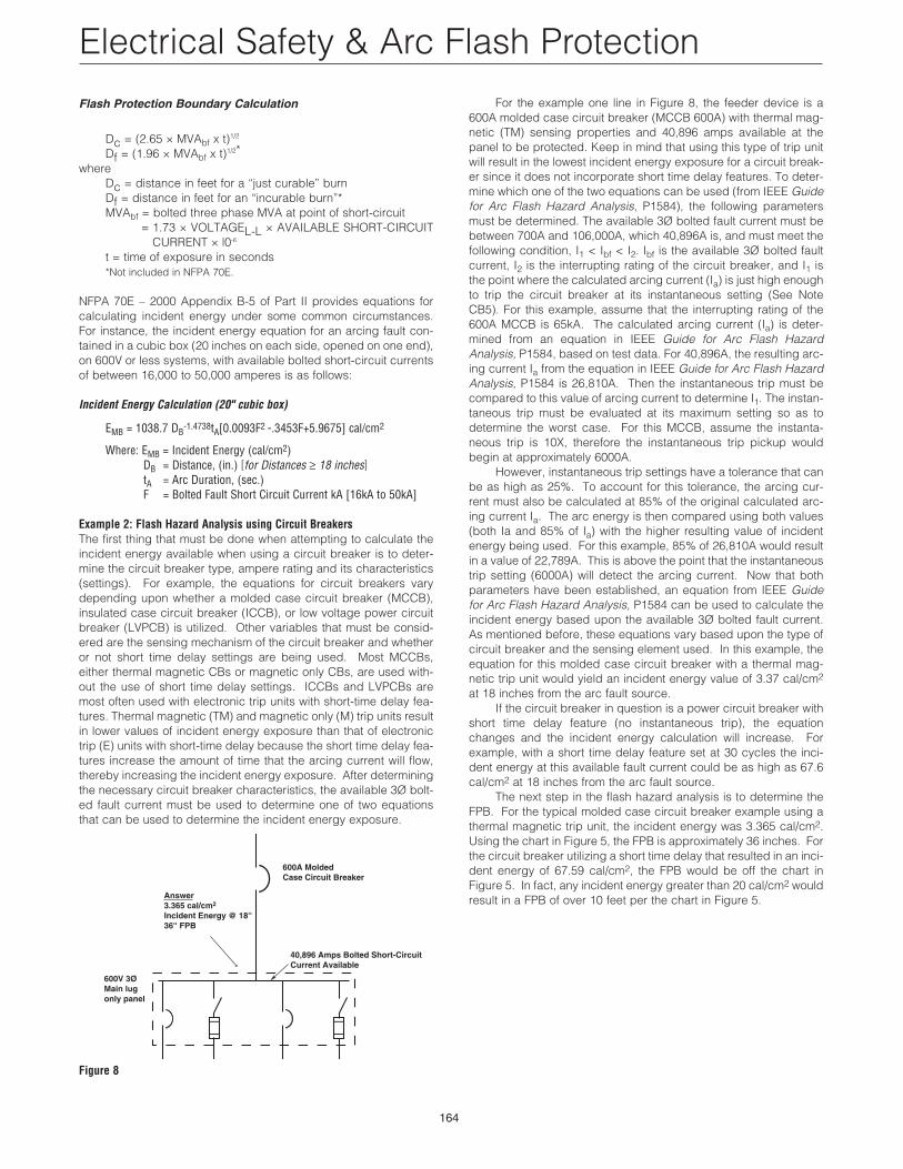
Example 2: Flash Hazard Analysis using Circuit BreakersThe first thing that must be done when attempting to calculate theincident energy available when using a circuit breaker is to deter-mine the circuit breaker type, ampere rating and its characteristics(settings). For example, the equations for circuit breakers varydepending upon whether a molded case circuit breaker (MCCB),insulated case circuit breaker (ICCB), or low voltage power circuitbreaker (LVPCB) is utilized. Other variables that must be consid-ered are the sensing mechanism of the circuit breaker and whetheror not short time delay settings are being used. Most MCCBs,either thermal magnetic CBs or magnetic only CBs, are used with-out the use of short time delay settings. ICCBs and LVPCBs aremost often used with electronic trip units with short-time delay fea-tures. Thermal magnetic (TM) and magnetic only (M) trip units resultin lower values of incident energy exposure than that of electronictrip (E) units with short-time delay because the short time delay fea-tures increase the amount of time that the arcing current will flow,thereby increasing the incident energy exposure. After determiningthe necessary circuit breaker characteristics, the available 3Ø bolt-ed fault current must be used to determine one of two equationsthat can be used to determine the incident energy exposure.
Figure 8
600A MoldedCase Circuit Breaker
40,896 Amps Bolted Short-CircuitCurrent Available
600V 3ØMain lugonly panel
Answer3.365 cal/cm2
Incident Energy @ 18''36'' FPB
For the example one line in Figure 8, the feeder device is a600A molded case circuit breaker (MCCB 600A) with thermal mag-netic (TM) sensing properties and 40,896 amps available at thepanel to be protected. Keep in mind that using this type of trip unitwill result in the lowest incident energy exposure for a circuit break-er since it does not incorporate short time delay features. To deter-mine which one of the two equations can be used (from IEEE Guidefor Arc Flash Hazard Analysis, P1584), the following parametersmust be determined. The available 3Ø bolted fault current must bebetween 700A and 106,000A, which 40,896A is, and must meet thefollowing condition, I1 < Ibf < I2. Ibf is the available 3Ø bolted faultcurrent, I2 is the interrupting rating of the circuit breaker, and I1 isthe point where the calculated arcing current (Ia) is just high enoughto trip the circuit breaker at its instantaneous setting (See NoteCB5). For this example, assume that the interrupting rating of the600A MCCB is 65kA. The calculated arcing current (Ia) is deter-mined from an equation in IEEE Guide for Arc Flash HazardAnalysis, P1584, based on test data. For 40,896A, the resulting arc-ing current Ia from the equation in IEEE Guide for Arc Flash HazardAnalysis, P1584 is 26,810A. Then the instantaneous trip must becompared to this value of arcing current to determine I1. The instan-taneous trip must be evaluated at its maximum setting so as todetermine the worst case. For this MCCB, assume the instanta-neous trip is 10X, therefore the instantaneous trip pickup wouldbegin at approximately 6000A.
However, instantaneous trip settings have a tolerance that canbe as high as 25%. To account for this tolerance, the arcing cur-rent must also be calculated at 85% of the original calculated arc-ing current Ia. The arc energy is then compared using both values(both Ia and 85% of Ia) with the higher resulting value of incidentenergy being used. For this example, 85% of 26,810A would resultin a value of 22,789A. This is above the point that the instantaneoustrip setting (6000A) will detect the arcing current. Now that bothparameters have been established, an equation from IEEE Guidefor Arc Flash Hazard Analysis, P1584 can be used to calculate theincident energy based upon the available 3Ø bolted fault current.As mentioned before, these equations vary based upon the type ofcircuit breaker and the sensing element used. In this example, theequation for this molded case circuit breaker with a thermal mag-netic trip unit would yield an incident energy value of 3.37 cal/cm2
at 18 inches from the arc fault source. If the circuit breaker in question is a power circuit breaker with
short time delay feature (no instantaneous trip), the equationchanges and the incident energy calculation will increase. Forexample, with a short time delay feature set at 30 cycles the inci-dent energy at this available fault current could be as high as 67.6cal/cm2 at 18 inches from the arc fault source.
The next step in the flash hazard analysis is to determine theFPB. For the typical molded case circuit breaker example using athermal magnetic trip unit, the incident energy was 3.365 cal/cm2.Using the chart in Figure 5, the FPB is approximately 36 inches. Forthe circuit breaker utilizing a short time delay that resulted in an inci-dent energy of 67.59 cal/cm2, the FPB would be off the chart inFigure 5. In fact, any incident energy greater than 20 cal/cm2 wouldresult in a FPB of over 10 feet per the chart in Figure 5.
165
Let’s summarize the steps necessary to conduct a Flash HazardAnalysis when using circuit breakers.1. Determine the available 3Ø bolted fault current on the line side
terminals of the equipment that will be worked upon.2. Determine the type of upstream circuit breaker to be used along
with the type of trip unit that will be used.3. Determine the ampacity of the upstream circuit breaker.4. Verify that the 3Ø bolted fault current meets the parameter of I1 <
Ibf < I2, where Ibf is the available 3Ø bolted fault current, I2 is theinterrupting rating of the breaker, and I1 is the point where thecalculated arcing current Ia is just high enough to trip the circuitbreaker at its instantaneous setting It.
5. To establish I1 from step 4, calculate the arcing current Ia.6. Calculate 85% of the arcing current Ia, calculated in step 5. 7. Determine the instantaneous trip setting It of the upstream circuit
breaker. If the circuit breaker does not have an instantaneoussetting due to a short time delay, use the short time pickup for It.
8. Use the 85% of Ia value along with It to determine I1. 9. Determine which equation from IEEE Guide for Arc Flash Hazard
Analysis, P1584 should be used to calculate the incident energyexposure.
10. Determine the Flash Protection Boundary that will require PPEbased upon the incident energy. This can also be simplified byusing the chart for Flash Protection Boundary in Figure 7.
11. Identify the minimum requirements for PPE when work is to beperformed inside of the FPB by consulting the minimum require-ments found in NFPA 70E. See Note CB 1.
Circuit Breaker Method Notes:See the General Notes under the Simple Fuse Chart Notes.
Note CB 1: The source for the method and data used in Example2 Circuit Breaker Flash Hazard Analysis is from the IEEE Guide forArc Flash Hazard Analysis, P1584. The circuit breaker informationcomes from theoretical equations that are based upon how circuitbreakers operate and arc-flash equations. These arc-flash equa-tions were created so that PPE chosen as a result of the equationswould be adequate for 95% of arc-flash incidents. In up to 5% ofincidents, incurable burns to the body and torso could result. Thiswas based upon PPE with standard ATPVs of 1.2, 8, 25, 40 and 100cal/cm2. PPE with intermediate ATPV values can be used, but at thenext lower standard ATPV rating.
Note CB2: As discussed in the IEEE Guide for Arc Flash HazardAnalysis, P1584, to calculate the incident energy for the circuitbreakers, the available 3Ø bolted fault current must be between700A and 106,000 amps. The available 3Ø bolted fault currentmust also be within the range of I1 < Ibf < I2. Where I2 is the inter-rupting rating of the circuit breaker and I1 is the lowest currentwhere the available 3Ø bolted fault current generates an arcing cur-rent large enough to be picked up by the instantaneous trip of thecircuit breaker.
Note CB3: The calculated arcing current is determined from anequation based upon test data. Actual results of arcing current maybe higher or lower than calculated.
Note CB4: When the 3Ø bolted fault current is below I1 for the cir-cuit breaker, the arcing current must be used in conjunction withtwo incident energy equations, found in IEEE Guide for Arc FlashHazard Analysis, P1584.
Note CB5: 85% of the arcing current must be used to determine I1.This adjusted value of arcing current is used with the incident ener-gy equations as in Note CB1, and the higher value of incident ener-gy must be used.
Note CB6: Instantaneous trip settings for circuit breakers should beassumed to be at their maximum setting. If calculations are donebased upon the minimum setting and the maximum setting is used,results may be extremely inaccurate.
Flash Protection Boundary Comparison for Test 3 and Test 4Refer back to the pictures for Test 3 and Test 4 on a previous pagein this section.
Using the charts in Figures 6 and 7 (which are derived fromIEEE Guide for Arc Flash Hazard Analysis, P1584), the circuit in Test3, protected by a KRP-C-601SP fuse, had an incident energy expo-sure of 1.5 cal/cm2 and a FPB of approximately 20 inches. Basedupon the equations from IEEE Guide for Arc Flash Hazard Analysis,P1584, the circuit in Test 4, protected by a 640 amp circuit breakerwith a short time delay setting, had an incident energy exposure of37.6 cal/cm2, a FPB greater than 10 feet. NFPA 70E gives require-ments for PPE that would have minimized the potential for the work-er to sustain life-threatening injuries due to burns from the arc-flash.However, the PPE that is currently available may not protect againstthe pressures and shrapnel from the resulting arc-blast in these twoincidents. Sensors on the chest of the mannequin in Test 3 measureda pressure of 504 lbs/ft2, which is below the threshold for eardrumrupture of 720 lbs/ft2. The pressure sensors in Test 4 however, mea-sured a pressure that exceeded 2160 lbs/ft2, which is greater thanthe threshold for lung damage. Not only could these pressurescause injury to the worker, both tests may have thrown the workeracross the room or subjected the worker to the dangers of fallingwhen working in an elevated space.
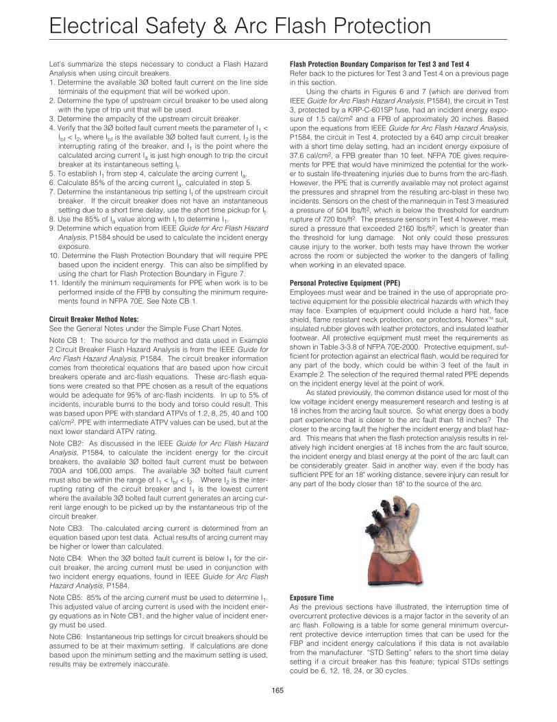
Personal Protective Equipment (PPE)Employees must wear and be trained in the use of appropriate pro-tective equipment for the possible electrical hazards with which theymay face. Examples of equipment could include a hard hat, faceshield, flame resistant neck protection, ear protectors, NomexTM suit,insulated rubber gloves with leather protectors, and insulated leatherfootwear. All protective equipment must meet the requirements asshown in Table 3-3.8 of NFPA 70E-2000. Protective equipment, suf-ficient for protection against an electrical flash, would be required forany part of the body, which could be within 3 feet of the fault inExample 2. The selection of the required thermal rated PPE dependson the incident energy level at the point of work.
As stated previously, the common distance used for most of thelow voltage incident energy measurement research and testing is at18 inches from the arcing fault source. So what energy does a bodypart experience that is closer to the arc fault than 18 inches? Thecloser to the arcing fault the higher the incident energy and blast haz-ard. This means that when the flash protection analysis results in rel-atively high incident energies at 18 inches from the arc fault source,the incident energy and blast energy at the point of the arc fault canbe considerably greater. Said in another way, even if the body hassufficient PPE for an 18" working distance, severe injury can result forany part of the body closer than 18" to the source of the arc.
Exposure Time As the previous sections have illustrated, the interruption time ofovercurrent protective devices is a major factor in the severity of anarc flash. Following is a table for some general minimum overcur-rent protective device interruption times that can be used for theFBP and incident energy calculations if this data is not availablefrom the manufacturer. “STD Setting” refers to the short time delaysetting if a circuit breaker has this feature; typical STDs settingscould be 6, 12, 18, 24, or 30 cycles.
Electrical Safety & Arc Flash Protection
166
Type of Device Minimum Time (Seconds)*Current-limiting fuse .004Circuit Breaker (5KV & 15KV) .1Standard molded case circuit
breakers (600V & below)without short-time-delay (STD) .0083-.0167with short-time-delay (STD) STD Setting
Insulated case circuit breakers(600V & below)
without short-time-delay .033with short-time-delay STD Setting
Low voltage power (air frame)circuit breakers (600V & below)
without-short-time-delay .05with short-time-delay STD Setting
Current-limiting molded casecircuit breaker (600V & below) .004
* These are approximate times for short-circuit currents within thecurrent-limiting range of a fuse or within the instantaneous region ofcircuit breakers. Lower current values may cause the overcurrentdevice to operate more slowly. Arc-flash energy may actually behighest at lower levels of available short-circuit current. This requiresthat arc flash energy calculations be completed for the range of sus-tainable arcing currents. Where equivalent RMS let-through data (thisis reduced let-through current due to current-limitation) is available, itcan be used in the flash distance and incident energy formulae onpage 164. Where data is unavailable, the full available short-circuitmust be used.
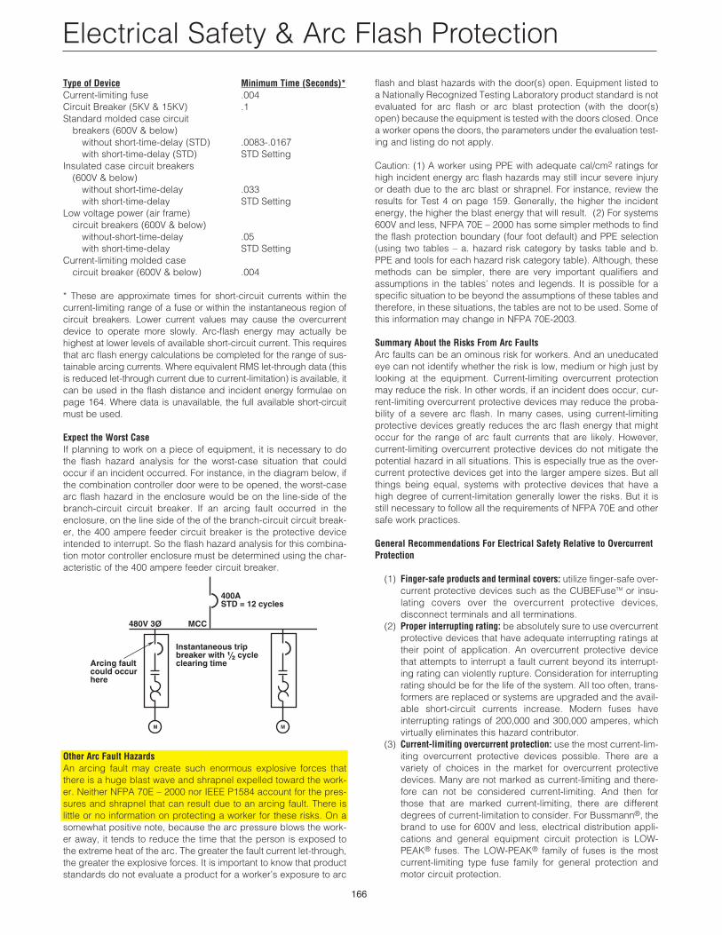
Expect the Worst CaseIf planning to work on a piece of equipment, it is necessary to dothe flash hazard analysis for the worst-case situation that couldoccur if an incident occurred. For instance, in the diagram below, ifthe combination controller door were to be opened, the worst-casearc flash hazard in the enclosure would be on the line-side of thebranch-circuit circuit breaker. If an arcing fault occurred in theenclosure, on the line side of the of the branch-circuit circuit break-er, the 400 ampere feeder circuit breaker is the protective deviceintended to interrupt. So the flash hazard analysis for this combina-tion motor controller enclosure must be determined using the char-acteristic of the 400 ampere feeder circuit breaker.
Other Arc Fault HazardsAn arcing fault may create such enormous explosive forces thatthere is a huge blast wave and shrapnel expelled toward the work-er. Neither NFPA 70E – 2000 nor IEEE P1584 account for the pres-sures and shrapnel that can result due to an arcing fault. There islittle or no information on protecting a worker for these risks. On asomewhat positive note, because the arc pressure blows the work-er away, it tends to reduce the time that the person is exposed tothe extreme heat of the arc. The greater the fault current let-through,the greater the explosive forces. It is important to know that productstandards do not evaluate a product for a worker’s exposure to arc
400ASTD = 12 cycles
480V 3O MCC
M M
Arcing fault could occur here
Instantaneous trip breaker with ⁄Ω™ cycle clearing time
flash and blast hazards with the door(s) open. Equipment listed toa Nationally Recognized Testing Laboratory product standard is notevaluated for arc flash or arc blast protection (with the door(s)open) because the equipment is tested with the doors closed. Oncea worker opens the doors, the parameters under the evaluation test-ing and listing do not apply.
Caution: (1) A worker using PPE with adequate cal/cm2 ratings forhigh incident energy arc flash hazards may still incur severe injuryor death due to the arc blast or shrapnel. For instance, review theresults for Test 4 on page 159. Generally, the higher the incidentenergy, the higher the blast energy that will result. (2) For systems600V and less, NFPA 70E – 2000 has some simpler methods to findthe flash protection boundary (four foot default) and PPE selection(using two tables – a. hazard risk category by tasks table and b.PPE and tools for each hazard risk category table). Although, thesemethods can be simpler, there are very important qualifiers andassumptions in the tables’ notes and legends. It is possible for aspecific situation to be beyond the assumptions of these tables andtherefore, in these situations, the tables are not to be used. Some ofthis information may change in NFPA 70E-2003.
Summary About the Risks From Arc FaultsArc faults can be an ominous risk for workers. And an uneducatedeye can not identify whether the risk is low, medium or high just bylooking at the equipment. Current-limiting overcurrent protectionmay reduce the risk. In other words, if an incident does occur, cur-rent-limiting overcurrent protective devices may reduce the proba-bility of a severe arc flash. In many cases, using current-limitingprotective devices greatly reduces the arc flash energy that mightoccur for the range of arc fault currents that are likely. However,current-limiting overcurrent protective devices do not mitigate thepotential hazard in all situations. This is especially true as the over-current protective devices get into the larger ampere sizes. But allthings being equal, systems with protective devices that have ahigh degree of current-limitation generally lower the risks. But it isstill necessary to follow all the requirements of NFPA 70E and othersafe work practices.
General Recommendations For Electrical Safety Relative to OvercurrentProtection
(1) Finger-safe products and terminal covers: utilize finger-safe over-current protective devices such as the CUBEFuseTM or insu-lating covers over the overcurrent protective devices,disconnect terminals and all terminations.
(2) Proper interrupting rating: be absolutely sure to use overcurrentprotective devices that have adequate interrupting ratings attheir point of application. An overcurrent protective devicethat attempts to interrupt a fault current beyond its interrupt-ing rating can violently rupture. Consideration for interruptingrating should be for the life of the system. All too often, trans-formers are replaced or systems are upgraded and the avail-able short-circuit currents increase. Modern fuses haveinterrupting ratings of 200,000 and 300,000 amperes, whichvirtually eliminates this hazard contributor.
(3) Current-limiting overcurrent protection: use the most current-lim-iting overcurrent protective devices possible. There are avariety of choices in the market for overcurrent protectivedevices. Many are not marked as current-limiting and there-fore can not be considered current-limiting. And then forthose that are marked current-limiting, there are differentdegrees of current-limitation to consider. For Bussmann®, thebrand to use for 600V and less, electrical distribution appli-cations and general equipment circuit protection is LOW-PEAK® fuses. The LOW-PEAK® family of fuses is the mostcurrent-limiting type fuse family for general protection andmotor circuit protection.
Electrical Safety & Arc Flash Protection
167
Electrical Safety & Arc Flash Protection
(4) Upgrade existing fuse systems: if the electrical system is anexisting fusible system, consider replacing the existing fuseswith the LOW-PEAK® family of fuses. If the existing fuses inthe clips are not the most current-limiting type fuses, upgrad-ing to the LOW-PEAK® family of fuses can reduce the haz-ards associated with arc flash. www.bussmann.com has aservice for the LOW-PEAK® upgrade.
(5) Install current-limiting overcurrent protection for actual loads: ifthe actual maximum full load current on an existing main,feeder or branch circuit is significantly below its designed cir-cuit ampacity, replace the existing fuses with lower ampererated LOW-PEAK® fuses. Or, if the OCPD is a circuit breaker,put a fused disconnect with LOW-PEAK® fuses in series withthe circuit breaker. For instance, an industrial found that manyof their 800 ampere feeders to their MCCs were lightly loaded;so for better arc flash protection they installed 400 and 600amp current-limiting fuses and switches in the feeders.
(6) Reliable overcurrent protection: use overcurrent protectivedevices that are reliable and do not require maintenance toassure performance per the original specifications. Modernfuses are reliable and retain their ability to react quickly underfault conditions. When a fuse is replaced, a new factory cali-brated fuse is put into service – the circuit has reliable protec-tion with performance equal to the original specifications. Ifmechanical overcurrent protective devices are utilized, besure to perform the manufacturer’s recommended periodicexercise, maintenance, testing and possible replacement.When an arc fault or overcurrent occurs, the overcurrent pro-tective device must be able to operate as intended. Thus, formechanical overcurrent protective devices, this may requiretesting, maintenance, and possible replacement before reset-ting the device after a fault interruption.
(7) Within sight motor disconnects: install HP rated disconnects(with permanently installed lockout provision) within sight andwithin 50 feet of every motor or driven machine. This measurefosters safer work practices and can be used for an emer-gency disconnect if there is an incident.
Flash Protection Field Marking: New NEC® Requirement
110.16 Flash ProtectionSwitchboards, panelboards, industrial control panels, and motorcontrol centers in other than dwelling occupancies, that are like-ly to require examination, adjustment, servicing, or maintenancewhile energized, shall be field marked to warn qualified personsof potential electric arc flash hazards. The marking shall belocated so as to be clearly visible to qualified persons beforeexamination, adjustment, servicing, or maintenance of theequipment.
FPN No. 1: NFPA 70E-2000, Electrical Safety Requirements forEmployee Workplaces, provides assistance in determiningseverity of potential exposure, planning safe work practices,and selecting personal protective equipment.
FPN No. 2: ANSI Z535.4-1998, Product Safety Signs and Labels,provides guidelines for the design of safety signs and labels forapplication to products.
Reprinted from NEC® 2002
This new requirement is intended to reduce the occurrence of seri-ous injury or death due to arcing faults to workers who work on ornear energized electrical equipment. The warning label shouldremind a qualified worker who intends to open the equipment foranalysis or work that a serious hazard exists and that the workershould follow appropriate work practices and wear appropriate per-sonal protective equipment (PPE) for the specific hazard (a non-qualified worker must not be opening or be near open energizedequipment).
110.16 only requires that this label state the existence of an arcflash hazard.
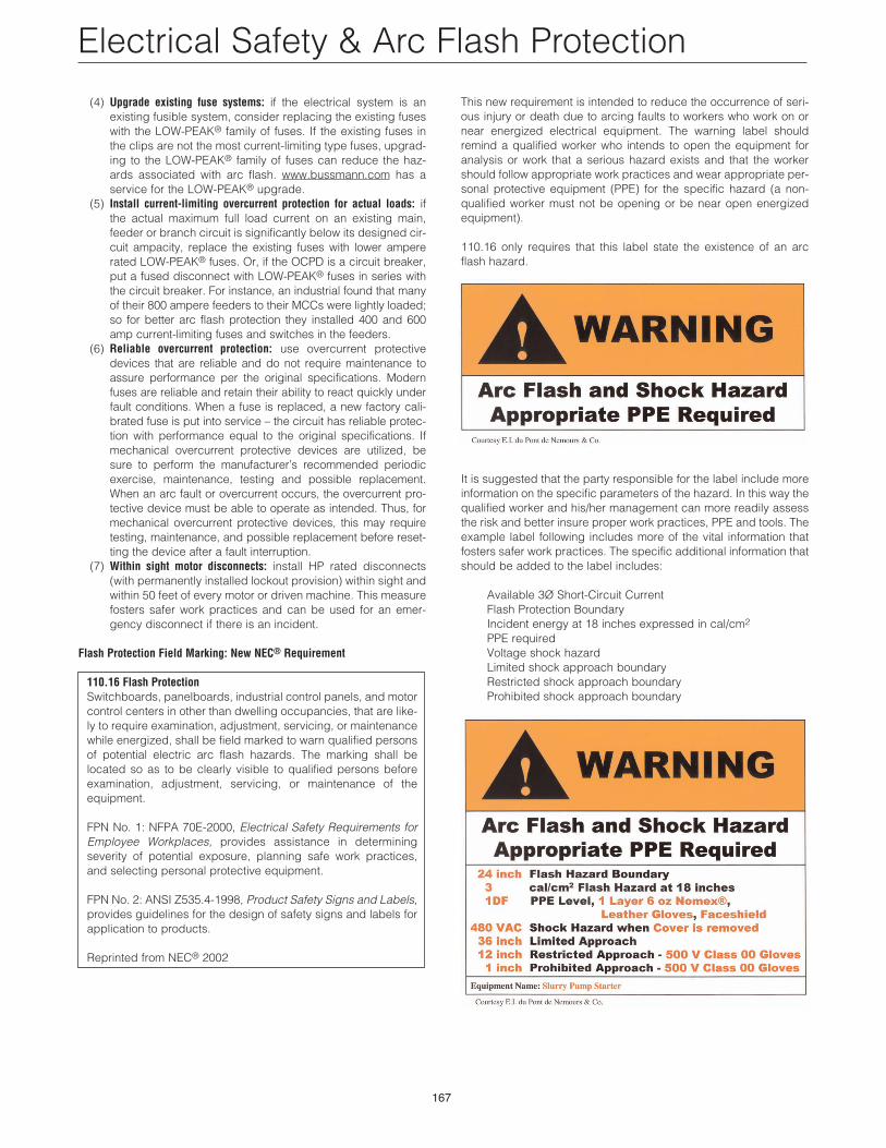
It is suggested that the party responsible for the label include moreinformation on the specific parameters of the hazard. In this way thequalified worker and his/her management can more readily assessthe risk and better insure proper work practices, PPE and tools. Theexample label following includes more of the vital information thatfosters safer work practices. The specific additional information thatshould be added to the label includes:
Available 3Ø Short-Circuit CurrentFlash Protection BoundaryIncident energy at 18 inches expressed in cal/cm2
PPE requiredVoltage shock hazardLimited shock approach boundaryRestricted shock approach boundaryProhibited shock approach boundary