electrical installations for impressed current cathodic ... · pdf fileguide electrical...
TRANSCRIPT
GUIDE
Electrical Installations for Impressed Current Cathodic Protection Systems
December 2008
2008-1035
2100, 350 – 7Avenue S.W.Calgary, AlbertaCanada T2P 3N9Tel (403) 267-1100Fax (403) 261-4622
403, 235 Water StreetSt. John’s, Newfoundland and LabradorCanada A1C 1B6Tel (709) 724-4200Fax (709) 724-4225
www.capp.ca ü [email protected]
The Canadian Association of Petroleum Producers (CAPP) represents 130 companies that explore for, develop and produce natural gas, natural gas liquids, crude oil, oil sands, and elemental sulphur throughout Canada. CAPP member companies produce more than 95 per cent of Canada’s natural gas and crude oil. CAPP also has 150 associate members that provide a wide range of services that support the upstream crude oil and natural gas industry. Together, these members and associate members are an important part of a $120-billion-a-year national industry that affects the livelihoods of more than half a million Canadians.
Disclaimer
This publication was prepared for the Canadian Association of Petroleum Producers (CAPP) by the CAPP Electrical Safety Subcommittee. While it is believed that the information contained herein is reliable under the conditions and subject to the limitations set out, CAPP and the CAPP Electrical Safety Subcommittee do not guarantee its accuracy. The use of this report or any information contained will be at the user’s sole risk, regardless of any fault or negligence of the CAPP Electrical Safety Subcommittee, CAPP or its co-funders.
Overview
Impressed Current Cathodic Protection systems are a technique for controlling the corrosion of a metal surface by making that surface the cathode of an electrochemical cell. Impressed Current Cathodic Protection systems are in widespread use at thousands of oil and gas surface production facilities, and serve to prevent failure of piping and other facilities which may lead to uncontrolled release of products, resulting in safety hazards and environmental contamination.
This guide is intended to help those designing, installing, inspecting, or maintaining impressed current cathodic protection systems meet minimum regulatory requirements; and it also simultaneously benefits worker safety and reliability of the system. It outlines, from an electrical perspective, design and installation criteria related to impressed current cathodic protection systems, including:
• codes and standards related to cathodic protection work• worker qualification• equipment certification • connection and splicing methods• installations• warning signs• documentation• electrical inspectionsAlthough mandatory language is used in this guideline, this guideline as a whole is non-mandatory in nature and is not a regulatory document. The adoption and enforcement of a practice or specification (or parts of it) is for the specific company or organization to determine in light of its own particular operations. However, the user should note that many of the elements of this guideline are also regulatory requirements. Therefore, if a user wishes to deviate from parts of this document, the user must be aware of the relevant minimum regulatory requirements. In addition, use of this guide is not a substitute for knowledge of regulatory requirements and each company and organization is responsible for its own regulatory compliance.
The guide has been developed in cooperation with representatives of the cathodic protection industry; corrosion specialists, and electrical technical staff from user companies. This guide is also endorsed by the CAPP Electrical Safety Sub-Committee of the Canadian Association of Petroleum Producers (CAPP).
The first edition of the guide has been developed for Alberta. Consideration may be given for other jurisdictions at a later time.
Contents
Overview .................................................................................................................................. ii
1 Purpose...................................................................................................................... 1-1
2 Scope......................................................................................................................... 2-22.1 Excluded from the Scope of this Guide...................................................... 2-2
2.1.1 Design of Cathodic Protection Systems......................................... 2-22.1.2 Work Procedures for Pipes and Vessels ........................................ 2-2
3 Codes and Standards................................................................................................ 3-3
3.1 Canadian Electrical Code........................................................................... 3-33.1.1 Section 80 ........................................................................................ 3-33.1.2 Section 10-200................................................................................. 3-3
3.2 Code for Electrical Installations at Oil and Gas Facilities ...................... 3-33.3 Occupational Health and Safety Code ....................................................... 3-33.4 CSA Z662 Oil and Gas Pipeline Systems................................................... 3-43.5 Canadian Gas Association Recommended Practice OCC-1-2005........... 3-43.6 NACE RP0169 Control of External Corrosion on Underground or Submerged
Metallic Piping Systems .............................................................................. 3-43.7 Corporate Standards .................................................................................... 3-4
4 Worker Qualifications and Equipment Certification ............................................. 4-54.1 Alberta .......................................................................................................... 4-54.2 Other Provinces............................................................................................ 4-54.3 Equipment Certification .............................................................................. 4-5
5 General Technical Requirements for Connections to Structures .......................... 5-75.1 Cross-Sectional Area ................................................................................... 5-75.2 Resistivity..................................................................................................... 5-7
5.2.1 Copper.............................................................................................. 5-75.2.2 Carbon Steel .................................................................................... 5-75.2.3 Stainless Steel.................................................................................. 5-8
5.3 Contact Surfaces .......................................................................................... 5-85.4 Frost Heave .................................................................................................. 5-8
6 Connection Methods ................................................................................................ 6-1
6.1 General ......................................................................................................... 6-16.2 Carbon Steel Bracket with Servit Post ....................................................... 6-1
6.2.1 Construction..................................................................................... 6-16.2.2 Engineering...................................................................................... 6-1
6.2.3 Applications..................................................................................... 6-16.3 Pipe Connections – Ground Clamp ............................................................ 6-1
6.3.1 Construction..................................................................................... 6-16.3.2 Engineering...................................................................................... 6-26.3.3 Applications..................................................................................... 6-2
6.4 Thermit Connections ................................................................................... 6-26.4.1 Construction..................................................................................... 6-26.4.2 Engineering...................................................................................... 6-26.4.3 Applications..................................................................................... 6-2
6.5 “LB” Fitting and Plate Connection............................................................. 6-26.5.1 Construction..................................................................................... 6-26.5.2 Engineering...................................................................................... 6-36.5.3 Applications..................................................................................... 6-3
6.6 Pipe Connections – U-Clamp...................................................................... 6-36.6.1 Construction..................................................................................... 6-36.6.2 Engineering...................................................................................... 6-36.6.3 Applications..................................................................................... 6-3
7 Splicing and Terminations....................................................................................... 7-4
7.1 Splicing......................................................................................................... 7-47.2 Terminations ................................................................................................ 7-4
8 Current Control Systems.......................................................................................... 8-58.1 Current Controllers ...................................................................................... 8-58.2 Electrical Insulation Devices ...................................................................... 8-5
8.2.1 Potential By-Pass............................................................................. 8-58.2.2 Potential Spark Source.................................................................... 8-5
9 Installation ................................................................................................................ 9-6
9.1 Installation and Wiring................................................................................ 9-69.2 Burial Depth................................................................................................. 9-6
9.2.1 Canadian Electrical Code Requirements...................................... 9-69.2.2 Alberta Energy Resources Conservation Board............................ 9-69.2.3 Agricultural Activities .................................................................... 9-69.2.4 Variances ......................................................................................... 9-69.2.5 Warning Tape .................................................................................. 9-7
9.3 Wire Protection – Ground Emergence ....................................................... 9-79.3.1 Gasoline Dispenser Stations ........................................................... 9-79.3.2 Oil Field Installations...................................................................... 9-7
9.4 Wire Protection – Long Cable Runs........................................................... 9-79.5 Wire Identification....................................................................................... 9-7
10 Warning Signs ........................................................................................................10-8
10.1 Cathodic Protection Warning Signs .........................................................10-810.2 Electrical Insulation Device Warning Signs ............................................10-8
11 Documentation .......................................................................................................11-1
11.1 General Requirements for Drawings ........................................................11-111.2 Cathodic Protection System Layouts........................................................11-111.3 Plot Plan .....................................................................................................11-111.4 Area Classification.....................................................................................11-111.5 Rectifier Schematics and Manuals............................................................11-1
12 Electrical Inspection...............................................................................................12-212.1 General .......................................................................................................12-212.2 Accredited Corporations ...........................................................................12-212.3 Non-Accredited Corporations...................................................................12-2
13 References...............................................................................................................13-3
Figures
Figure 1: Example of a Servit Post Connection…………………… 6-1
Figure 2: Example of a Protective Bracket with Frost Loop or
“Pigtail”………………………………………………….. 6-1
Figure 3: Example of a Certified Ground Clamp Connection……... 6-2
Figure 4: Example of a Thermit Connection………………………. 6-2
Figure 5: Example of an LB Fitting and Plate Connection………… 6-3
Figure 6: Example of a Splice Connection………………………… 7-1

December 2008 Electrical Installations for Impressed Current Cathodic Protection Systems Page 1-1
1 Purpose
This guide is intended to set minimum electrical safety requirements for impressed current cathodic protection system installations. This guide also identifies work responsibilities and/or restrictions.
December 2008 Electrical Installations for Impressed Current Cathodic Protection Systems Page 2-2
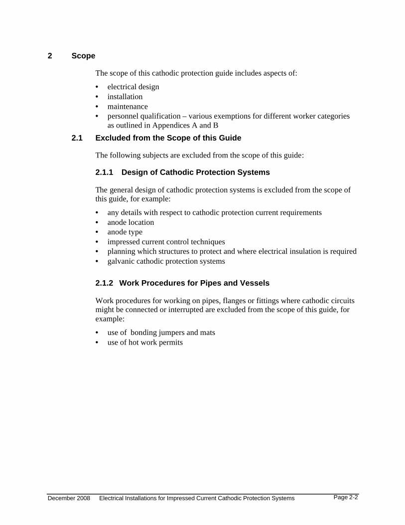
2 Scope
The scope of this cathodic protection guide includes aspects of:
• electrical design• installation• maintenance• personnel qualification – various exemptions for different worker categories
as outlined in Appendices A and B2.1 Excluded from the Scope of this Guide
The following subjects are excluded from the scope of this guide:
2.1.1 Design of Cathodic Protection Systems
The general design of cathodic protection systems is excluded from the scope of this guide, for example:
• any details with respect to cathodic protection current requirements • anode location• anode type• impressed current control techniques• planning which structures to protect and where electrical insulation is required• galvanic cathodic protection systems
2.1.2 Work Procedures for Pipes and Vessels
Work procedures for working on pipes, flanges or fittings where cathodic circuits might be connected or interrupted are excluded from the scope of this guide, for example:
• use of bonding jumpers and mats• use of hot work permits
December 2008 Electrical Installations for Impressed Current Cathodic Protection Systems Page 3-3
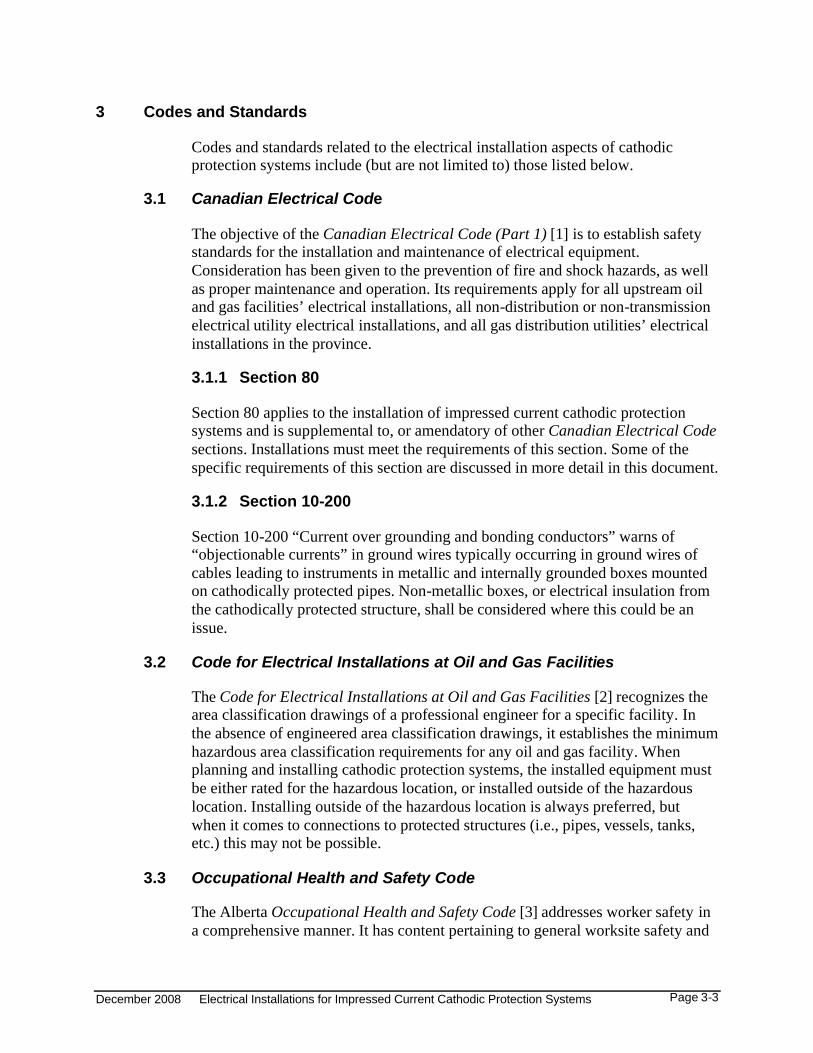
3 Codes and Standards
Codes and standards related to the electrical installation aspects of cathodic protection systems include (but are not limited to) those listed below.
3.1 Canadian Electrical Code
The objective of the Canadian Electrical Code (Part 1) [1] is to establish safety standards for the installation and maintenance of electrical equipment. Consideration has been given to the prevention of fire and shock hazards, as well as proper maintenance and operation. Its requirements apply for all upstream oil and gas facilities’ electrical installations, all non-distribution or non-transmission electrical utility electrical installations, and all gas distribution utilities’ electrical installations in the province.
3.1.1 Section 80
Section 80 applies to the installation of impressed current cathodic protection systems and is supplemental to, or amendatory of other Canadian Electrical Codesections. Installations must meet the requirements of this section. Some of the specific requirements of this section are discussed in more detail in this document.
3.1.2 Section 10-200
Section 10-200 “Current over grounding and bonding conductors” warns of “objectionable currents” in ground wires typically occurring in ground wires of cables leading to instruments in metallic and internally grounded boxes mounted on cathodically protected pipes. Non-metallic boxes, or electrical insulation from the cathodically protected structure, shall be considered where this could be an issue.
3.2 Code for Electrical Installations at Oil and Gas Facilities
The Code for Electrical Installations at Oil and Gas Facilities [2] recognizes the area classification drawings of a professional engineer for a specific facility. In the absence of engineered area classification drawings, it establishes the minimum hazardous area classification requirements for any oil and gas facility. When planning and installing cathodic protection systems, the installed equipment must be either rated for the hazardous location, or installed outside of the hazardous location. Installing outside of the hazardous location is always preferred, but when it comes to connections to protected structures (i.e., pipes, vessels, tanks, etc.) this may not be possible.
3.3 Occupational Health and Safety Code
The Alberta Occupational Health and Safety Code [3] addresses worker safety in a comprehensive manner. It has content pertaining to general worksite safety and
December 2008 Electrical Installations for Impressed Current Cathodic Protection Systems Page 3-4
procedures which govern all oilfield work. Some examples of where this code applies to the installation and servicing of cathodic protection systems include:
• lockout and tag procedures• hot work procedures and work in hazardous locations• working alone requirements• working in the vicinity of power lines
3.4 CSA Z662 Oil and Gas Pipeline Systems
CSA Z662 [4] covers design, construction, operation and maintenance of oil and gas industry pipeline systems. Section 9 covers Corrosion Control including electrical interference.
3.5 Canadian Gas Association Recommended Practice OCC-1-2005
Canadian Gas Association Recommended Practice OCC-1-2005 “Control of External Corrosion on Buried or Submerged Metallic Piping Systems” [5] applies to the control of external corrosion on buried or submerged metallic piping systems. This “Recommended Practice” is intended as a reference only. It is a company’s own responsibility to provide procedures that will satisfy all regulations, and their own requirements for effective, safe, and proactive corrosion control.
3.6 NACE RP0169 Control of External Corrosion on Underground or Submerged Metallic Piping Systems
This document contains a section on installation requirements (Section 8). Many of those requirements are also covered in more depth in this guideline within the context of the Canadian Electrical Code and other oil and gas industry cathodic protection (CP) practices. The NACE RP0169 [6] document also covers design, operations, maintenance, and documentation issues which are outside of the scope of this guideline.
3.7 Corporate Standards
Some upstream oil and gas companies may have their own engineering standards outlining cathodic protection installation details and maintenance procedures. Companies (who have accreditations in the electrical discipline) may also have specific variances permitting deviations from the Canadian Electrical Code.
December 2008 Electrical Installations for Impressed Current Cathodic Protection Systems Page 4-5
4 Worker Qualifications and Equipment Certification
4.1 Alberta
In Alberta, all electrical work up to and including the direct current (DC) output terminals of a cathodic protection rectifier falls under the Electrician Trade Regulation. [7] This regulation is put in place under the Apprenticeship and Industry Training Act. [8] The Electrician Trade Regulation restricts any type of electrical work to certified electricians. The rationales for this are related to personnel safety (shock), indirect safety issues (e.g. excessive heat, fire), knowledge of electrical engineering principles, and good workmanship.
CAPP in conjunction with Alberta Learning, has developed various training courses for non-electricians such as field operators, maintenance staff, and CP technicians. Together with hands-on training (provided by an electrician on the specific equipment), and authorization by the employer, these courses permit non-electricians to perform limited electrical work scope activities on CP systems:
• for operators and other field maintenance personnel, these include routine checks of impressed current levels, tap changes, and visual checks
• for CP technicians, these include basic maintenance on the DC side of the CP rectifier
See Appendix A for a brief description of the available exemption courses, and Appendix B for a scope definition diagram for CP technicians.
In Alberta, engineering practice is governed by the Engineering, Geological, and Geophysical Professions Act. [9]
4.2 Other Provinces
Other provinces have similar acts in place governing “electrical work” and “engineering”.
4.3 Equipment Certification
All equipment used in the electrical circuit(s) of cathodic protection systems must be certified to Canadian (CSA) Standards by an accredited certification body. The accredited certification bodies (such as the Canadian Standards Association, Underwriter’s Laboratories, Entela, etc.) are, in turn, accredited by the Standards Council of Canada. Equipment which is certified to Canadian standards is often referred to as “CSA Approved” or “CSA Certified”, but it can also be certified by one of these other accredited certification bodies and is equally acceptable. Information on approved certification organizations, and the recognized markings on equipment, is available from Alberta Municipal Affairs. For the purposes of this document, the terms “certified” or “approved” are used, and refer to equipment that is certified by an accredited certification body to Canadian standards.

December 2008 Electrical Installations for Impressed Current Cathodic Protection Systems Page 4-6
Exceptions to the certification requirements are possible for equipment types for which Canadian certification test standards are not available. Examples in the cathodic protection trade where these exceptions are needed include standalone variable and fixed resistors (which may only have a “component” certification); or engineered connections to structures. This document identifies when engineering involvement for the design of a piece of equipment is required.
December 2008 Electrical Installations for Impressed Current Cathodic Protection Systems Page 5-7
5 General Technical Requirements for Connections to Structures
5.1 Cross-Sectional Area
Rated rectifier current capacity and mechanical strength requirements will govern the minimum required wire cross-section. The ampacity of the selected copper wire cross- section will determine the minimum current rating of all components used in the current path.
Canadian Electrical Code Table D5 “Strandings for Building Wires and Cables” may be used for cross-sectional area conversions from AWG to mm2.
5.2 Resistivity
Resistivity is a property related to the electrical resistance of a material and is independent of the geometry of the specimen. It is, however, sensitive to the temperature and composition of the material. Using resistivity, the resistance for a wire of given material, length, cross-sectional area, and at a given temperature, can be computed using the formula [10]:
R = ρ l / A
where
R = resistance in ohms
ρ = resistivity in ohm-metres
l = length in metres, and
A = cross-sectional area in square-metres
5.2.1 Copper
The resistivity of pure copper is 1.678 x 10⁻⁸ •*m at 20οC [10].
5.2.2 Carbon Steel
Some carbon steels have approximately 10 times the resistivity of copper, depending upon the alloy and temperature. Therefore, for the same length of steel or copper conductor, the cross-section of any carbon steel component or structure in the current path has to be at least 10 times the cross-section of the copper conductor to have similar resistance, and thus produce comparable I2R (heating) losses, and comparable operating temperatures. This guide uses this “ten-times rule-of-thumb” for sizing carbon steel connections to structures.
If smaller carbon steel cross-sections are to be used, then further engineering analysis will be required. This is outside of the scope of this guide.
December 2008 Electrical Installations for Impressed Current Cathodic Protection Systems Page 5-8
5.2.3 Stainless Steel
Stainless steel has approximately 44 times the resistivity of copper. Therefore, the cross-section of any stainless steel construction piece in the current path has to be at least 44 times that of the copper wire used in the installation.
If smaller stainless steel cross-sections are to be used, then further engineering analysis will be required. This is outside of the scope of this guide.
5.3 Contact Surfaces
All electrical connections require good metal-to-metal contact (i.e. paint-, rust-, and grease-free; with buff surfaces). For atmospheric connections, consideration shall be given to protecting the metallic connection in corrosive environments (e.g.: salt, H2S, condensation, etc.) through the use of anti-corrosion paint.
5.4 Frost Heave
Frost heave may cause the cathodic protection wiring and the protected structure to move relative to one another. Sufficient slack may prevent separation of the wire from the structure. For example, the wire can be coiled in a flexible loop in the air (this is also known as a “pigtail”).
December 2008 Electrical Installations for Impressed Current Cathodic Protection Systems Page 6-1
6 Connection Methods
6.1 General
Visible open wire connections are preferred over “hidden” connections. Visible connections allow visual inspections for solid contact, corrosion, or frost heave damage.
All cathodic protection wires above grade have to be mechanically protectedand/or protected by location.
6.2 Carbon Steel Bracket with Servit Post
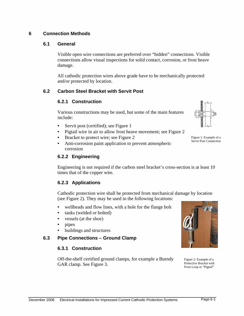
6.2.1 Construction
Various constructions may be used, but some of the main features include:
• Servit post (certified); see Figure 1• Pigtail wire in air to allow frost heave movement; see Figure 2• Bracket to protect wire; see Figure 2• Anti-corrosion paint application to prevent atmospheric
corrosion6.2.2 Engineering
Engineering is not required if the carbon steel bracket’s cross-section is at least 10 times that of the copper wire.
6.2.3 Applications
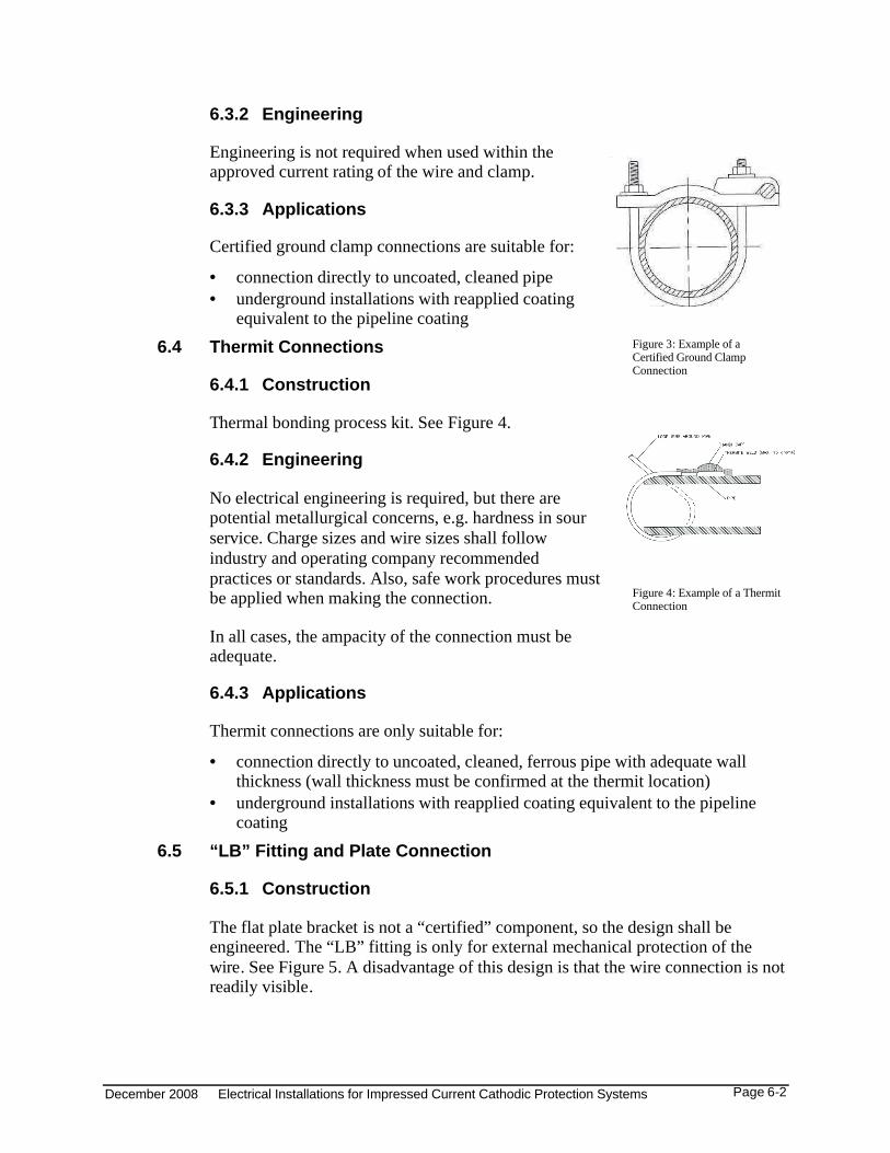
Cathodic protection wire shall be protected from mechanical damage by location (see Figure 2). They may be used in the following locations:
• wellheads and flow lines, with a hole for the flange bolt• tanks (welded or bolted)• vessels (at the shoe)• pipes • buildings and structures
6.3 Pipe Connections – Ground Clamp
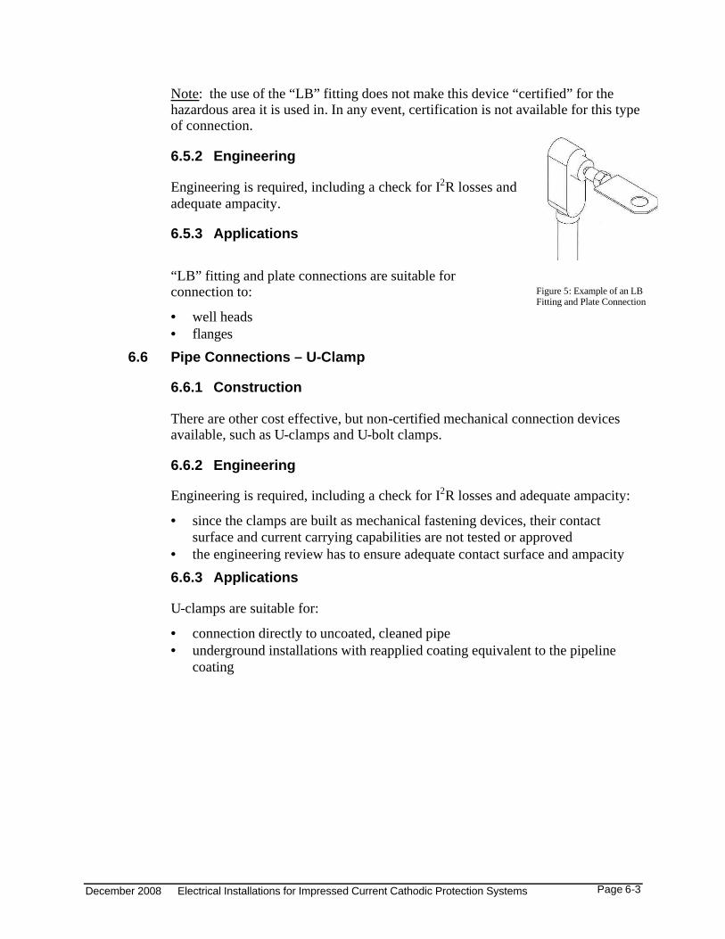
6.3.1 Construction
Off-the-shelf certified ground clamps, for example a Burndy GAR clamp. See Figure 3.
Figure 1: Example of a Servit Post Connection
Figure 2: Example of a Protective Bracket with Frost Loop or “Pigtail”
December 2008 Electrical Installations for Impressed Current Cathodic Protection Systems Page 6-2
6.3.2 Engineering
Engineering is not required when used within the approved current rating of the wire and clamp.
6.3.3 Applications
Certified ground clamp connections are suitable for:
• connection directly to uncoated, cleaned pipe• underground installations with reapplied coating
equivalent to the pipeline coating6.4 Thermit Connections
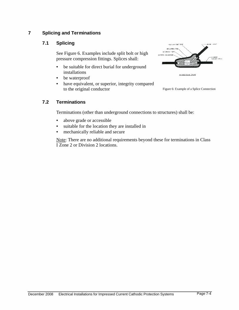
6.4.1 Construction
Thermal bonding process kit. See Figure 4.
6.4.2 Engineering
No electrical engineering is required, but there are potential metallurgical concerns, e.g. hardness in sour service. Charge sizes and wire sizes shall follow industry and operating company recommendedpractices or standards. Also, safe work procedures must be applied when making the connection.
In all cases, the ampacity of the connection must be adequate.
6.4.3 Applications
Thermit connections are only suitable for:
• connection directly to uncoated, cleaned, ferrous pipe with adequate wall thickness (wall thickness must be confirmed at the thermit location)
• underground installations with reapplied coating equivalent to the pipeline coating
6.5 “LB” Fitting and Plate Connection
6.5.1 Construction
The flat plate bracket is not a “certified” component, so the design shall be engineered. The “LB” fitting is only for external mechanical protection of the wire. See Figure 5. A disadvantage of this design is that the wire connection is not readily visible.
Figure 3: Example of a Certified Ground Clamp Connection
Figure 4: Example of a Thermit Connection
December 2008 Electrical Installations for Impressed Current Cathodic Protection Systems Page 6-3
Note: the use of the “LB” fitting does not make this device “certified” for the hazardous area it is used in. In any event, certification is not available for this type of connection.
6.5.2 Engineering
Engineering is required, including a check for I2R losses and adequate ampacity.
6.5.3 Applications
“LB” fitting and plate connections are suitable for connection to:
• well heads• flanges
6.6 Pipe Connections – U-Clamp
6.6.1 Construction
There are other cost effective, but non-certified mechanical connection devices available, such as U-clamps and U-bolt clamps.
6.6.2 Engineering
Engineering is required, including a check for I2R losses and adequate ampacity:
• since the clamps are built as mechanical fastening devices, their contact surface and current carrying capabilities are not tested or approved
• the engineering review has to ensure adequate contact surface and ampacity6.6.3 Applications
U-clamps are suitable for:
• connection directly to uncoated, cleaned pipe• underground installations with reapplied coating equivalent to the pipeline
coating
Figure 5: Example of an LB Fitting and Plate Connection
December 2008 Electrical Installations for Impressed Current Cathodic Protection Systems Page 7-4
7 Splicing and Terminations
7.1 Splicing
See Figure 6. Examples include split bolt or high pressure compression fittings. Splices shall:
• be suitable for direct burial for underground installations
• be waterproof• have equivalent, or superior, integrity compared
to the original conductor
7.2 Terminations
Terminations (other than underground connections to structures) shall be:
• above grade or accessible• suitable for the location they are installed in• mechanically reliable and secure
Note: There are no additional requirements beyond these for terminations in Class I Zone 2 or Division 2 locations.
Figure 6: Example of a Splice Connection
December 2008 Electrical Installations for Impressed Current Cathodic Protection Systems Page 8-5
8 Current Control Systems
8.1 Current Controllers
Since current controllers create heat, they shall be mounted outside of hazardous locations.
8.2 Electrical Insulation Devices
Electrical insulation devices are intended to prevent current from passing between specific structures (electrical insulation kits, dielectric unions).
8.2.1 Potential By-Pass
Accidental or unintended bypasses can defeat or degrade cathodic protection, or create arcing or sparking hazards in unexpected locations.
• Do not inadvertently bypass electrical insulation devices. • Be aware of forgotten tools, jumpers, damaged or removed electrical
insulation devices, thermal insulation cladding, glycol or electric heat tracing, electrical grounding systems, instrumentation lines, and any other potential parallel path.
8.2.2 Potential Spark Source
Many connections are in hazardous locations, so accidental shorting of flanges may lead to sparks, and a fire or explosion hazard.
• Warning signs shall be used at the locations of electrical insulation devices (see section 10.2).
• Flange shielding, for example taping or other external shielding, is recommended.
December 2008 Electrical Installations for Impressed Current Cathodic Protection Systems Page 9-6
9 Installation
9.1 Installation and Wiring
Electrical installation and wiring shall comply with the Canadian Electrical Code Part 1 C22.1 [1].
9.2 Burial Depth
Codes, standards, and factors to be considered:
9.2.1 Canadian Electrical Code Requirements
The Canadian Electrical Code has burial depth requirements in two sections:
Section 12-012 (Table 53)
• 900 mm burial below vehicular traffic• 600 mm burial below non-vehicular traffic• this rule is intended mainly for power cables where a significant shock, spark,
or arc flash hazard can existSection 80-002
• burial not less than 450 mm (if unprotected)• burial not less than 200 mm in raceway or protected
Follow Section 80-002, when no variance for burial depth is in place (see Section 9.2.4)
9.2.2 Alberta Energy Resources Conservation Board
The Alberta Energy Resources Conservation Board administers the AlbertaPipeline Act [11] and regulations which has requirements governing ground disturbance activities:
• procedures are required at depths of more than 300 mm• companies may have more stringent rules9.2.3 Agricultural Activities
Local plowing activities may require deeper burial depth than required in the Canadian Electrical Code.
9.2.4 Variances
Corporations accredited under the Alberta Safety Codes Act [12] may opt for aCanadian Electrical Code variance allowing burial depth of less than Canadian Electrical Code requirements. Some variances currently allow for a ground-grid wire depth of typically 300 mm. This may be extended to include cathodic protection wiring as well.
December 2008 Electrical Installations for Impressed Current Cathodic Protection Systems Page 9-7
9.2.5 Warning Tape
Warning tape, buried 150 mm above the cathodic protection cable, shall be used.
9.3 Wire Protection – Ground Emergence
9.3.1 Gasoline Dispenser Stations
The requirements mentioned in the Canadian Electrical Code sections
• CEC 80-002(3)(a) “conduit”, and• CEC 80-002(3)(b) “seals”apply only to conduit installations where hazardous vapours can migrate from a hazardous location (gasoline dispensing equipment) to another location (non-hazardous). It is assumed that conduit is run all the way between the hazardous and non-hazardous locations. When only a conduit sleeve riser is used, a seal is not required since migration to a general purpose location is not possible, as the conduit does not run all the way back to the non-hazardous location. The conduit sleeve riser is only intended to protect the vertical section of conductor, and extends into the ground only far enough to ensure conductor protection and adequate support.
9.3.2 Oil Field Installations
Accepted wire protection methods for directly buried wires include:
• conduit sleeve (metal or PVC) for risers, • planking or concrete• protection by location
9.4 Wire Protection – Long Cable Runs
As a good practice, underground cable warning signs may be placed every 300 m, or as appropriate, depending upon site requirements.
9.5 Wire Identification
The following techniques are used to ensure proper identification of wires:
• anode wires shall be black• wires for protected structures shall be any colour except black; they are often
white• markers shall be permanent and legible• wire tags (optional) should be referenced in drawings so that
circuits/conductors can be identified• colour coding and/or markers can be used where needed
December 2008 Electrical Installations for Impressed Current Cathodic Protection Systems Page 10-8
10 Warning Signs
10.1 Cathodic Protection Warning Signs
Refer to Canadian Electrical Code Section 80-012 for further details about warning sign requirements, for example, warning signs are required:
• for cathodically protected structures• on disconnect means• at entrances to tanks or vessels with impressed cathodically protected
immersed internal surfaces (Section 80-012(5))10.2 Electrical Insulation Device Warning Signs
Warning signs shall be installed near the locations of electrical insulation devices.
December 2008 Electrical Installations for Impressed Current Cathodic Protection Systems Page 11-1
11 Documentation
11.1 General Requirements for Drawings
All drawings typical for an electrical installation, as listed below, shall be supplied.
The cathodic protection service provider and owner’s electrical representative need to communicate in order to make provision for the CP installation design in the site electrical drawings.
A management of change process should be in place to update drawings and related documentation over the life of the facility.
11.2 Cathodic Protection System Layouts
Cathodic protection system layouts shall show:
• power source – load centre and circuit assignment• external disconnect location• cathodic protection panel location• installation details• other typical data
11.3 Plot Plan
The plot plan shall identify:
• routing from power source• location of cathodic protection panels• anode bed and anode panel locations• underground and above ground cable routing• location of connections to structures• electrical insulation kit locations• other equipment such as current control stations
11.4 Area Classification
Unless certified for the location, cathodic protection equipment shall be installed outside of hazardous areas. Therefore the site hazardous area classification drawing shall be referenced when planning the location of cathodic protection equipment and the layout of cathodic protection installations.
11.5 Rectifier Schematics and ManualsRectifier schematics and manuals shall be:
• accurate• in good condition• suitably stored
December 2008 Electrical Installations for Impressed Current Cathodic Protection Systems Page 12-2
12 Electrical Inspection
12.1 General
In principle, all cathodic protection installations are governed by Canadian Electrical Code requirements and are subject to government regulated code compliance inspections.
12.2 Accredited Corporations
Accredited corporations have their own electrical Safety Codes Officers inspecting the electrical aspects of cathodic protection installations for Canadian Electrical Code compliance.
12.3 Non-Accredited Corporations
Non-accredited corporations shall ensure that permits are taken out with the authority having jurisdiction for all cathodic protection installations.
December 2008 Electrical Installations for Impressed Current Cathodic Protection Systems Page 13-3
13 References
[1] C22.1-06, Canadian Electrical Code, Part I; Canadian Standards Association, Mississauga, Ontario, Canada; www.shopcsa.ca
[2] Code for Electrical Installations at Oil and Gas Facilities; Safety Codes Council of Alberta; Edmonton, Alberta, Canada; www.safetycodes.ab.ca
[3] Occupational Health and Safety Code; Government of Alberta - Human Resources and Employment; Edmonton, Alberta, Canada; www.qp.gov.ab.ca
[4] CSA Standard CAN/CSA-662, Oil and Gas Pipeline Systems; Canadian Standards Association, Mississauga, Ontario, Canada; www.shopcsa.ca
[5] Corrosion Control Subcommittee; 2005; Canadian Gas Association Recommended Practice OCC-1-2005 Control of External Corrosion on Buried or Submerged Metallic Piping Systems; Canadian Gas Association; Ottawa, Ontario, Canada; [email protected]
[6] NACE Standard RP0169: Control of External Corrosion on Underground or Submerged Metallic Pipeline Systems; National Association of Corrosion Engineers (NACE International); Houston, Texas, USA; www.nace.org
[7] Consolidated November 3, 2006; Alberta Regulation 274/2000: Electrician Trade Regulation; Government of Alberta - Advanced Education and Technology; Edmonton, Alberta, Canada; www.qp.gov.ab.ca
[8] Consolidated January 17, 2006; Alberta Regulation 274/2000: Apprenticeship and Industry Training Act; Government of Alberta - Advanced Education and Technology; Edmonton, Alberta, Canada; www.qp.gov.ab.ca
[9] Chapter E-11.1, Revised Statutes of Alberta, 2000; The Engineering, Geological, and Geophysical Professions Act; Government of Alberta; Edmonton, Alberta, Canada; www.qp.gov.ab.ca
[10] Dorf, Richard C.; 1993; The Electrical Engineering Handbook; CRC Press,Boca Raton, Florida, USA; pp. 5-6, 2527.
[11] Chapter P-15, Revised Statutes of Alberta, 2000; Pipeline Act; Government of Alberta; Edmonton, Alberta, Canada; www.qp.gov.ab.ca
[12] Chapter S-1, Revised Statutes of Alberta, 2000; Safety Codes Act; Government of Alberta; Edmonton, Alberta, Canada; www.qp.gov.ab.ca
July 2008 Electrical Installations for Impressed Current Cathodic Protection Systems Page A- i
Appendix A Electrical Qualifications Training for Work on Cathodic Protection Equipment
A.1 Safe Electrical Work with Cathodic Protection EquipmentAfter an incident in 2004 the cathodic protection service industry, in cooperation with the CAPP Electrical Safety Subcommittee, started a process to improve the Cathodic Protection industry’s safe work practices. To assist the cathodic protection industry and operating companies there are various courses available, to meet their electrical safety needs. A.2 “Electrical Maintenance for Non-Electricians” Course
• This course was developed in the late 1990’s to allow operators (non-electricians) employed by small oil companies to safely perform several very limited scope electrical work tasks. This course is offered by an oil and gas industry training organization called Enform.
• The scope of cathodic protection work allowed (after passing the course exam, equipment specific training by an electrician, and employer authorization) includes:• taking current readings• visual checks • fuse changes• tap adjustments
A.3 “Reading and Adjusting Rectifiers for Facility Operations Personnel”Course (“One-Day Field Operator Basic Readings Course”)
• A CP service provider, has developed a one-day course for their customers’ field operations personnel. This course allows field operations personnel to be able to take basic current readings and make minor adjustments to ensure that their rectifiers are working properly in between scheduled CP technician visits. This course has been developed under the supervision of the CAPP Electrical Safety Subcommittee.
• The scope of cathodic protection work allowed after passing this course, being trained on the specific equipment by an electrician, and being authorized by their employer is: • Isolation, lockout/tag, and de-energization verification• current readings• fuse changes• tap changer adjustments• visual checks
A.4 “Electrical Cathodic Protection Work Course for Non-Electricians” Course(“CP Technician Course”)
• A detailed course was developed by a CP service provider for the cathodic protection industry and approved by Apprenticeship and Industry Training and the Alberta Provincial Apprenticeship Committee (PAC). This course is currently offered in compliance with an Alberta Apprenticeship and Industry Training authorization.
• Scope of Work includes:• Isolation and lockout/tagout• Routine servicing and maintenance on the DC side of the system
July 2008 Electrical Installations for Impressed Current Cathodic Protection Systems Page B- ii
• Like-for-like component replacement on the DC side of the system• Installation and maintenance of DC conductors connecting to protected structures• As with an apprenticeship, there are a minimum number of hours of directly supervised
hands on work required before the CP Technician can work independently.• CP Technicians with this exemption are required to carry a certification card.
July 2008 Electrical Installations for Impressed Current Cathodic Protection Systems Page B- i
Appendix B Work Responsibilities or Restrictions for Cathodic Protection Systems from a Trade Perspective
December 2008 Electrical Installations for Impressed Current Cathodic Protection Systems Page B-ii
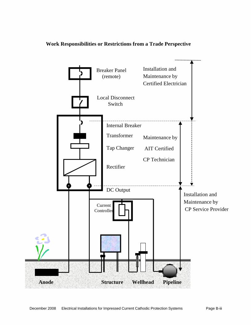
B.1 Trades Scope Diagram
The following diagram delineates the boundaries between electrician and cathodic protection technician work scopes.
Note: Per the Electrician Trade Regulation, an electrician can legally work on the DC side of the rectifier system and beyond the DC terminals on the output of the rectifier, but it is recommended that electricians only do this with CP industry cathodic protection equipment and trades practices training.
December 2008 Electrical Installations for Impressed Current Cathodic Protection Systems Page B-iii
Breaker Panel(remote)
Local DisconnectSwitch
Internal Breaker
Transformer
Tap Changer
Rectifier
DC Output
Work Responsibilities or Restrictions from a Trade Perspective
Anode Structure
CurrentController
Wellhead Pipeline
Installation and
CP Service Provider
Maintenance by
Installation and Maintenance byCertified Electrician
AIT Certified
CP Technician
Maintenance by