electric part-turn actuators - auma-usa.com part-turn actuators operation ... technical data...
TRANSCRIPT

Electric part-turn actuators
Operation instructions
SG 05.1 – SG 12.1SGR 05.1 – SGR 12.1
AUMA NORMfor flange type FA
Part-turn actuators SG 05.1 – SG 12.1 / SGR 05.1 – SGR 12.1AUMA NORM Operation instructions
Table of contents Page
1. Safety instructions 41.1 Range of application 41.2 Commissioning (electrical connection) 41.3 Maintenance 41.4 Warnings and notes 4
2. Short description 4
3. Technical data 5
4. Transport, storage and packaging 74.1 Transport 74.2 Storage 74.3 Packaging 7
5. Manual operation 8
6. Mounting to valve 9
7. Electrical connection 107.1 Connection with AUMA plug/socket connector 107.2 Delay time 107.3 Reversal time 107.4 Controls made by AUMA 117.5 Heater 117.6 Motor protection 117.7 Remote position transmitter 117.8 Limit and torque switches 117.9 Fitting the cover 11
8. Setting the end stops for part-turn actuators on butterfly valves 128.1 Setting end stop CLOSED 128.2 Setting end stop OPEN 128.3 Setting limit switching CLOSED 12
9. Setting the end stops for part-turn actuators on ball valves 139.1 Setting end stop OPEN 139.2 Setting end stop CLOSED 139.3 Setting limit switching OPEN 13
10. Changing the swing angle 1410.1 Increasing the swing angle 1410.2 Reducing the swing angle 14
11. Opening the switch compartment 1511.1 Removing the cover from the switch compartment 1511.2 Pulling off the indicator disc 15
12. Setting the limit switching 1612.1 Setting end position CLOSED (black section) 1612.2 Setting end position OPEN (white section) 1612.3 Checking the limit switches 16
13. Setting the DUO limit switching (option) 1713.1 Setting direction CLOSE (black section) 1713.2 Setting direction OPEN (white section) 1713.3 Checking the DUO limit switches 17
Scope of these instructions: These instructions are valid for part-turn actuators of the type rangesSG 05.1 – SG 12.1 and SGR 05.1 – SGR 12.1 in version AUMA NORM.These operation instructions are only valid for “clockwise closing”, i.e.driven shaft turns clockwise to close the valve.

Part-turn actuators SG 05.1 – SG 12.1 / SGR 05.1 – SGR 12.1Operation instructions AUMA NORM
14. Setting the torque switching 1814.1 Setting 1814.2 Checking the torque switches 18
15. Test run 1915.1 Checking the direction of rotation 1915.2 Checking the limit switching 19
16. Setting the potentiometer (option) 20
17. Setting the electronic position transmitter RWG (option) 2117.1 Setting 2-wire system 4 – 20 mA and 3- /4-wire system 0 – 20 mA 2217.2 Setting 3-/4- wire system 4 – 20 mA 23
18. Setting the mechanical position indicator 24
19. Closing the switch compartment 24
20. Setting the operating time 25
21. Enclosure protection IP 68 (option) 26
22. Maintenance 27
23. Lubrication 27
24. Disposal and recycling 28
25. Service 28
26. Spare parts list part-turn actuator SG(R) 05.1 – SG(R) 12.1 with plug/socket connector 29
Index 31
Addresses of AUMA offices and representatives 32
1. Safety instructions1.1 Range of application AUMA actuators are designed for the operation of industrial valves,
e.g. butterfly valves and ball valves.For other applications, please consult us. The manufacturer is not liable forany possible damage resulting from use in other than the designated appli-cations. Such risk lies entirely with the user.Observance of these operation instructions is considered as part of theactuator’s designated use.
1.2 Commissioning(electrical connection)
During electrical operation, certain parts inevitably carry lethal voltages.Work on the electrical system or equipment must only be carried out by askilled electrician himself or by specially instructed personnel under thecontrol and supervision of such an electrician and in accordance with theapplicable electrical engineering rules.
1.3 Maintenance The maintenance instructions (refer to page 27) must be observed, other-wise a safe operation of the actuator is no longer guaranteed.
1.4 Warnings and notes Failure to observe the warnings and notes may lead to serious injuries ordamage. Qualified personnel must be thoroughly familiar with all warningsand notes in these operation instructions.Correct transport, proper storage, mounting and installation, as well ascareful commissioning are essential to ensure a trouble-free and safe oper-ation.During operation, the multi-turn actuator warms up and surface tempera-tures > 140 °F may occur. Check the surface temperature prior to contact inorder to avoid burns.
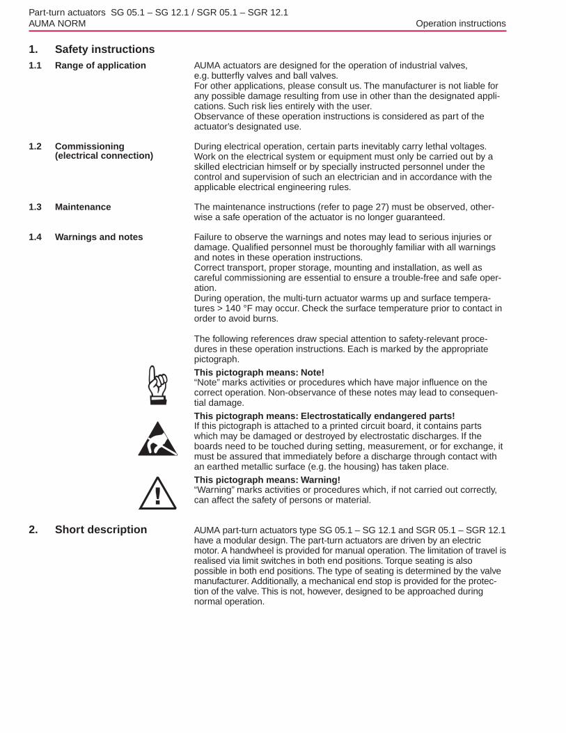
The following references draw special attention to safety-relevant proce-dures in these operation instructions. Each is marked by the appropriatepictograph.This pictograph means: Note!“Note” marks activities or procedures which have major influence on thecorrect operation. Non-observance of these notes may lead to consequen-tial damage.This pictograph means: Electrostatically endangered parts!If this pictograph is attached to a printed circuit board, it contains partswhich may be damaged or destroyed by electrostatic discharges. If theboards need to be touched during setting, measurement, or for exchange, itmust be assured that immediately before a discharge through contact withan earthed metallic surface (e.g. the housing) has taken place.This pictograph means: Warning!“Warning” marks activities or procedures which, if not carried out correctly,can affect the safety of persons or material.
2. Short description AUMA part-turn actuators type SG 05.1 – SG 12.1 and SGR 05.1 – SGR 12.1have a modular design. The part-turn actuators are driven by an electricmotor. A handwheel is provided for manual operation. The limitation of travel isrealised via limit switches in both end positions. Torque seating is alsopossible in both end positions. The type of seating is determined by the valvemanufacturer. Additionally, a mechanical end stop is provided for the protec-tion of the valve. This is not, however, designed to be approached duringnormal operation.
Part-turn actuators SG 05.1 – SG 12.1 / SGR 05.1 – SGR 12.1AUMA NORM Operation instructions
3. Technical data
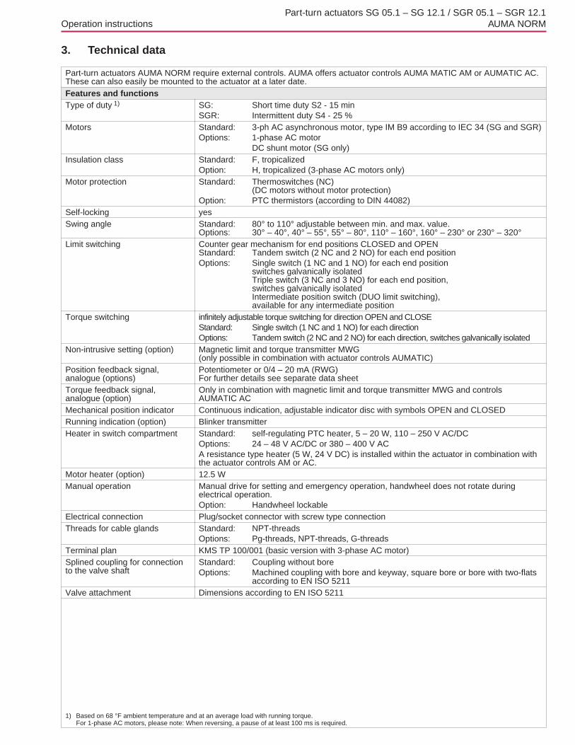
Part-turn actuators AUMA NORM require external controls. AUMA offers actuator controls AUMA MATIC AM or AUMATIC AC.These can also easily be mounted to the actuator at a later date.Features and functionsType of duty 1) SG: Short time duty S2 - 15 min
SGR: Intermittent duty S4 - 25 %Motors Standard: 3-ph AC asynchronous motor, type IM B9 according to IEC 34 (SG and SGR)
Options: 1-phase AC motorDC shunt motor (SG only)
Insulation class Standard: F, tropicalizedOption: H, tropicalized (3-phase AC motors only)
Motor protection Standard: Thermoswitches (NC)(DC motors without motor protection)
Option: PTC thermistors (according to DIN 44082)Self-locking yesSwing angle Standard: 80° to 110° adjustable between min. and max. value.
Options: 30° – 40°, 40° – 55°, 55° – 80°, 110° – 160°, 160° – 230° or 230° – 320°Limit switching Counter gear mechanism for end positions CLOSED and OPEN
Standard: Tandem switch (2 NC and 2 NO) for each end positionOptions: Single switch (1 NC and 1 NO) for each end position
switches galvanically isolatedTriple switch (3 NC and 3 NO) for each end position,switches galvanically isolatedIntermediate position switch (DUO limit switching),available for any intermediate position
Torque switching infinitely adjustable torque switching for direction OPEN and CLOSEStandard: Single switch (1 NC and 1 NO) for each directionOptions: Tandem switch (2 NC and 2 NO) for each direction, switches galvanically isolated
Non-intrusive setting (option) Magnetic limit and torque transmitter MWG(only possible in combination with actuator controls AUMATIC)
Position feedback signal,analogue (options)
Potentiometer or 0/4 – 20 mA (RWG)For further details see separate data sheet
Torque feedback signal,analogue (option)
Only in combination with magnetic limit and torque transmitter MWG and controlsAUMATIC AC
Mechanical position indicator Continuous indication, adjustable indicator disc with symbols OPEN and CLOSEDRunning indication (option) Blinker transmitterHeater in switch compartment Standard: self-regulating PTC heater, 5 – 20 W, 110 – 250 V AC/DC
Options: 24 – 48 V AC/DC or 380 – 400 V ACA resistance type heater (5 W, 24 V DC) is installed within the actuator in combination withthe actuator controls AM or AC.
Motor heater (option) 12.5 WManual operation Manual drive for setting and emergency operation, handwheel does not rotate during
electrical operation.Option: Handwheel lockable
Electrical connection Plug/socket connector with screw type connectionThreads for cable glands Standard: NPT-threads
Options: Pg-threads, NPT-threads, G-threadsTerminal plan KMS TP 100/001 (basic version with 3-phase AC motor)Splined coupling for connectionto the valve shaft
Standard: Coupling without boreOptions: Machined coupling with bore and keyway, square bore or bore with two-flats
according to EN ISO 5211Valve attachment Dimensions according to EN ISO 5211
1) Based on 68 °F ambient temperature and at an average load with running torque.For 1-phase AC motors, please note: When reversing, a pause of at least 100 ms is required.
Part-turn actuators SG 05.1 – SG 12.1 / SGR 05.1 – SGR 12.1Operation instructions AUMA NORM

Service conditionsEnclosure protection accordingto EN 60 529 2)
Standard: IP 67Options: IP 68
IP 67-DS (Double Sealed)IP 68-DS (Double Sealed)(Double Sealed = additional protection of the interior of the housingagainst ingress of dust and dirt when removing the plug)
Corrosion protection Standard: KN Suitable for installation in industrial units, in water or power plantswith a low pollutant concentration
Options: KS Suitable for installation in occasionally or permanently aggressiveatmosphere with a moderate pollutant concentration(e.g. in wastewater treatment plants, chemical industry)
KX Suitable for installation in extremely aggressive atmospherewith high humidity and high pollutant concentration
KX-G same as KX, however aluminium-free version (outer parts)Finish coating Standard: Two-component iron-mica combinationStandard colour Standard: Dark grey (DB 702, similar to RAL 9007)
Option: Other colours are possible on requestAmbient temperature 3) Standard SG: – 20 to + 80 °C/ – 20 to + 175 °F (with 3-phase AC motor)
– 25 to + 70 °C / – 20 to + 158 °F(with 1-phase AC and DC motor)Standard SGR: – 25 to + 60 °C/ – 20 to + 140 °F (with 3-phase AC motor)Options: – 40 to + 60 °C – 40 to + 140 °F(low temperature)
– 50 to + 60 °C/ – 75 to + 140 °F (extreme low temperature)(SG with 3-phase AC current only)
Lifetime SG 05.1/SG 07.1: 20,000 operating cycles (OPEN - CLOSE - OPEN) for 90°SG 10.1: 15,000 operating cycles (OPEN - CLOSE - OPEN) for 90°SG 12.1: 10,000 operating cycles (OPEN - CLOSE - OPEN) for 90°SGR 05.1 – 12.1:4) min. 2.5 million operations (control steps)
Other informationEU Directives Electromagnetic Compatibility (EMC): (89/336/EEC)
Low Voltage Directive: (73/23/EEC)Machinery Directive: (98/37/EC)
Reference documents Product description “Electric part-turn actuators SG”Dimension sheets SGElectrical data SG/SGR
2) For version in enclosure protection IP 68, higher corrosion protection KS or KX is strongly recommended Additionally, for enclosure protection IP 68, werecommend to use the double sealed terminal compartment DS
3) Version with RWG min. – 40 °F (40 °C) and max. + 158 °F (70 °C)4) The lifetime depends on the load and the number of starts. A high starting frequency will rarely improve the modulating accuracy. To reach the longest possible
maintenance and fault-free operation time, the number of starts per hour chosen should be as low as permissible for the process
Part-turn actuators SG 05.1 – SG 12.1 / SGR 05.1 – SGR 12.1AUMA NORM Operation instructions

4. Transport, storage and packaging4.1 Transport .For transport to place of installation, use sturdy packaging..Do not attach ropes or hooks to the handwheel for the purpose of lifting by
hoist.. If part-turn actuator is mounted on valve, attach ropes or hooks for thepurpose of lifting by hoist to valve and not to part-turn actuator.
Fitting the ball handle: To avoid damage during transport, the ball handles are fitted to the inside ofthe handwheel. Prior to commissioning, the ball handle has to be fitted inthe correct position..Remove cap nut (figure A)..Pull out ball handle and re-insert in correct position..Fasten with cap nut..Remove label from the handwheel for fitting the ball handle.
4.2 Storage .Store in well-ventilated, dry room..Protect against floor dampness by storage on a shelf or ona wooden pallet..Cover to protect against dust and dirt..Apply suitable corrosion protection agent to uncoated surfaces.
If part-turn actuators are to be stored for a long time (more than 6 months),the following points must be observed additionally:.Prior to storage: Protect uncoated surfaces, in particular the output drive
parts and mounting surface, with long-term corrosion protection agent..Check for corrosion approximately every 6 months. If first signs of corro-sion show, apply new corrosion protection.
After mounting, connect part-turn actuator immediately toelectrical mains, so that condensation is prevented by theheater.
4.3 Packaging Our products are protected by special packaging for the transport ex works.The packaging consists of environmentally friendly materials which caneasily be separated and recycled.We use the following packaging materials: wood, cardboard, paper, andPolyurethane foam. For the disposal of the packaging material, we recom-mend recycling and collection centers.
Part-turn actuators SG 05.1 – SG 12.1 / SGR 05.1 – SGR 12.1Operation instructions AUMA NORM
Figure A
Cap nut
Ball handle
Ball handle

5. Manual operationThe actuator may be operated manually for purposes of setting andcommissioning, and in case of motor failure or power failure.
Engaging manual operation: Manual operation is activated by pulling at the handwheel. A change-over isnot required. The handwheel does not rotate during motor operation..Turning the handwheel during motor operation results in
an extension or reduction of the operating time, dependingon the direction of rotation.. It is not necessary to use an extension for manual opera-tion. Excessive force may cause damage.
Disengaging manual operation: Release handwheel.Handwheel has to engage.
Part-turn actuators SG 05.1 – SG 12.1 / SGR 05.1 – SGR 12.1AUMA NORM Operation instructions

6. Mounting to valve .Prior to mounting, the part-turn actuator must be checkedfor any damage. Damaged parts must be replaced by origi-nal spare parts..After mounting, check part-turn actuator for damage topaint finish. If damage to paint-finish has occurred aftermounting, it has to be touched up to avoid corrosion.
.For butterfly valves, the recommended mounting position is end positionCLOSED (Prior to mounting, bring the part-turn actuator to the mechan-ical end stop CLOSED by turning the handwheel clockwise.)..For ball valves, the recommended mounting position is end positionOPEN (Prior to mounting, bring the part-turn actuator to the mechanicalend stop OPEN by turning the handwheel counterclockwise.)..Thoroughly degrease mounting faces of part-turn actuator and valve..Apply a small quantity of grease to the valve shaft..Place coupling sleeve onto valve shaft and secure(refer to figure B, detail A or B), ensure that dimensions X, Y, and Z areobserved (refer to table 1)..Apply non-acidic grease at splines of coupling..Fit actuator so that fixing holes in actuator and valve mounting flange arein alignment.If necessary, move actuator up or down one tooth on the coupling. Ifrequired, turn handwheel/crank a little in direction OPEN or CLOSE untilholes align to the threads..Ensure that the spigot (if provided) mates uniformly in the recess and thatthe mounting faces are in complete contact..Fasten the actuator with bolts of minimum strength class grade 5 usinglock washers. Fasten bolts evenly crosswise to the appropriate torqueaccording to table 1.
Part-turn actuators SG 05.1 – SG 12.1 / SGR 05.1 – SGR 12.1Operation instructions AUMA NORM
A
X
B
Z
Y
Figure B
Coupling
Valve
Set screw
Type X max. Y max. Z max. Qty. xthreads(UNC)
TA [ft lbs]
SG(R) 05.1-FA07 5 3 60 4 x 516 -18 19
SG(R) 07.1-FA07 7 3 60 4 x 516 -18 19
SG(R) 10.1-FA12 10 3 77 4 x 12 - 13 78
SG(R) 12.1-FA12 10 6 100 4 x 12 - 13 78
Conversion factor: 1 Nm corresponds to 1.3529 ft lbs.
Table 1: Dimensions for couplings/fastening torques for bolts
7. Electrical connection Work on the electrical system or equipment must only becarried out by a skilled electrician himself or by speciallyinstructed personnel under the control and supervision ofsuch an electrician and in accordance with the applicableelectrical engineering rules.
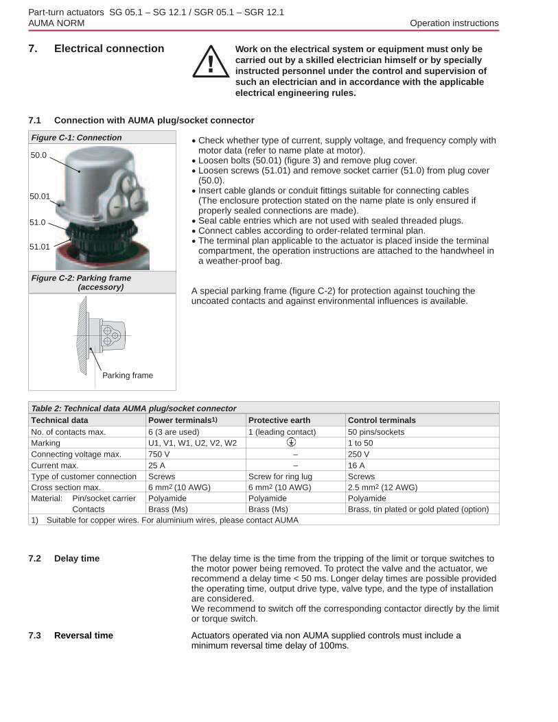
7.1 Connection with AUMA plug/socket connector.Check whether type of current, supply voltage, and frequency comply withmotor data (refer to name plate at motor)..Loosen bolts (50.01) (figure 3) and remove plug cover..Loosen screws (51.01) and remove socket carrier (51.0) from plug cover(50.0).. Insert cable glands or conduit fittings suitable for connecting cables(The enclosure protection stated on the name plate is only ensured ifproperly sealed connections are made)..Seal cable entries which are not used with sealed threaded plugs..Connect cables according to order-related terminal plan..The terminal plan applicable to the actuator is placed inside the terminalcompartment, the operation instructions are attached to the handwheel ina weather-proof bag.
A special parking frame (figure C-2) for protection against touching theuncoated contacts and against environmental influences is available.
7.2 Delay time The delay time is the time from the tripping of the limit or torque switches tothe motor power being removed. To protect the valve and the actuator, werecommend a delay time < 50 ms. Longer delay times are possible providedthe operating time, output drive type, valve type, and the type of installationare considered.We recommend to switch off the corresponding contactor directly by the limitor torque switch.
7.3 Reversal time Actuators operated via non AUMA supplied controls must include aminimum reversal time delay of 100ms.
Part-turn actuators SG 05.1 – SG 12.1 / SGR 05.1 – SGR 12.1AUMA NORM Operation instructions
Figure C-1: Connection
50.0
50.01
51.0
51.01
Technical data Power terminals1) Protective earth Control terminalsNo. of contacts max. 6 (3 are used) 1 (leading contact) 50 pins/socketsMarking U1, V1, W1, U2, V2, W2 1 to 50Connecting voltage max. 750 V – 250 VCurrent max. 25 A – 16 AType of customer connection Screws Screw for ring lug ScrewsCross section max. 6 mm2 (10 AWG) 6 mm2 (10 AWG) 2.5 mm2 (12 AWG)Material: Pin/socket carrier Polyamide Polyamide Polyamide
Contacts Brass (Ms) Brass (Ms) Brass, tin plated or gold plated (option)1) Suitable for copper wires. For aluminium wires, please contact AUMA
Table 2: Technical data AUMA plug/socket connector
Figure C-2: Parking frame(accessory)
Parking frame

7.4 Controls made by AUMA In case the required reversing contactors are not to be installed in thecontrol cabinet, the controls AUMA MATIC or AUMATIC can easily bemounted to the actuator at a later date.For enquiries and more information, please state our commission no.(refer to actuator name plate).
7.5 Heater AUMA part-turn actuators have a heater installed as standard. To preventcondensation, the heater must be connected.
7.6 Motor protection In order to protect against overheating and extreme high temperatures atthe actuator, PTC thermistors or thermoswitches are embedded in the motorwinding. The thermoswitch is tripped as soon as the max. permissiblewinding temperature has been reached.
Failure to integrate PTC thermistors or thermoswitches into the controlcircuit voids the warranty for the motor.
7.7 Remote position transmitter For the connection of remote position transmitters (potentiometer, RWG),shielded cables must be used.
7.8 Limit and torque switches
Only the same potential can be switched on the two circuits (NC/NOcontact) of a limit or torque switch. If different potentials are to be switchedsimultaneously, tandem switches are required.To ensure correct actuator indicationss, the leading contacts of the tandemswitches must be used for that purpose and the lagging contacts for motorswitching off.
7.9 Fitting the cover After connection:. Insert the socket carrier (51.0) into the plug cover (50.0) and fasten it withscrews (51.01)..Clean sealing faces at the plug cover and the housing..Check whether O-ring is in good condition..Apply a thin film of non-acidic grease (e.g. Vaseline) to the sealing faces..Replace plug cover (50.0) and fasten bolts (50.01) evenly crosswise..Fasten cable glands with the specified torque to ensure the requiredenclosure protection.
Part-turn actuators SG 05.1 – SG 12.1 / SGR 05.1 – SGR 12.1Operation instructions AUMA NORM
RD
BK
RD
BK
BK
2
RD
2
BK
RD
BK
2
RD
2
BK
RD
TSC 1 / TSO 1LSC 1 / LSO 1
TSC / TSOLSC / LSO
DSR 1 / DÖL 1WSR 1 / WÖL 1
DSR / DÖLWSR / WÖL
Figure 4
I Single switch
II Tandem switch
SPDT
DPDT
Mechanicallife time = 2 x 10⁶ starts
Type of current Switch rating Imax
30 V 125 V 250 V1-phase AC(ind. load) cos phi = 0.8 5 A 5 A 5 A
DC(resistive load) 2 A 0.5 A 0.4 A
with gold plated contacts min. 5 V, max. 50 VCurrent min. 4 mA, max. 400 mA
Table 3: Technical data limit/torque switches
NO NCNC NO
8. Setting the end stops for part-turn actuators on butterfly valves
For actuators on ball valves refer to page 13, section 9.
The settings can only be performed if the valve has not yet been mounted ina pipeline. . If part-turn actuators are supplied without a valve:
hex. bolts (03, figure E) are not tightened.. If part-turn actuators are supplied with a valve:hex. bolts (03, figure E) are tightened.End stops and limit switching should have already beenset and only have to be checked.
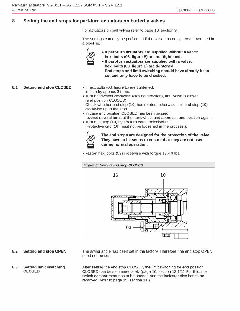
8.1 Setting end stop CLOSED . If hex. bolts (03, figure E) are tightened:loosen by approx. 3 turns..Turn handwheel clockwise (closing direction), until valve is closed(end position CLOSED).Check whether end stop (10) has rotated, otherwise turn end stop (10)clockwise up to the stop.. In case end position CLOSED has been passed:reverse several turns at the handwheel and approach end position again..Turn end stop (10) by 1/8 turn counterclockwise(Protective cap (16) must not be loosened in the process.).
The end stops are designed for the protection of the valve.They have to be set as to ensure that they are not usedduring normal operation.
.Fasten hex. bolts (03) crosswise with torque 18.4 ft lbs.
8.2 Setting end stop OPEN The swing angle has been set in the factory. Therefore, the end stop OPENneed not be set.
8.3 Setting limit switchingCLOSED
After setting the end stop CLOSED, the limit switching for end positionCLOSED can be set immediately (page 16, section 13.12.). For this, theswitch compartment has to be opened and the indicator disc has to beremoved (refer to page 15, section 11.).
Part-turn actuators SG 05.1 – SG 12.1 / SGR 05.1 – SGR 12.1AUMA NORM Operation instructions
16 10
03
Figure E: Setting end stop CLOSED
9. Setting the end stops for part-turn actuators on ball valves
For actuators on butterfly valves refer to page 12, section 8.
The settings can only be performed if the valve has not yet been mounted ina pipeline. . If part-turn actuators are supplied without a valve:
hex. bolts (03, figure F) are not tightened.. If part-turn actuators are supplied with a valve:hex. bolts (03, figure F) are tightened.End stops and limit switching should have already beenset and only have to be checked.
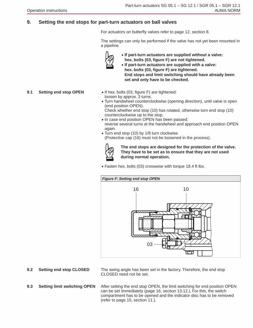
9.1 Setting end stop OPEN . If hex. bolts (03, figure F) are tightened:loosen by approx. 3 turns..Turn handwheel counterclockwise (opening direction), until valve is open(end position OPEN).Check whether end stop (10) has rotated, otherwise turn end stop (10)counterclockwise up to the stop.. In case end position OPEN has been passed:reverse several turns at the handwheel and approach end position OPENagain..Turn end stop (10) by 1/8 turn clockwise.(Protective cap (16) must not be loosened in the process).
The end stops are designed for the protection of the valve.They have to be set as to ensure that they are not usedduring normal operation.
.Fasten hex. bolts (03) crosswise with torque 18.4 ft lbs.
9.2 Setting end stop CLOSED The swing angle has been set in the factory. Therefore, the end stopCLOSED need not be set.
9.3 Setting limit switching OPEN After setting the end stop OPEN, the limit switching for end position OPENcan be set immediately (page 16, section 13.12.). For this, the switchcompartment has to be opened and the indicator disc has to be removed(refer to page 15, section 11.).
Part-turn actuators SG 05.1 – SG 12.1 / SGR 05.1 – SGR 12.1Operation instructions AUMA NORM
16 10
03
Figure F: Setting end stop OPEN

10. Changing the swing angle The swing angle only has to be changed if the swing range for setting theend stops (sections 8. and 9.) is not sufficient.
Unless ordered otherwise, the swing angle is set to 90°.In the standard version, the swing angle can be adjusted within the range of80° to 110°.For optional swing angle ranges, refer to Technical data, page 5.
10.1 Increasing the swing angle .Unscrew protective cap (16) (figure G)..While holding end stop nut (2.4) in position with open end wrench(19 mm), remove set screw (2.02)..Turn end stop nut (2.4) counterclockwise.Do not exceed dimension A max. (table 4)..Move valve manually to the desired end position OPEN..Turn end stop nut (2.4) clockwise until it is tight up to the stop nut (7)..Degrease face of set screw (2.02)..Hold end stop nut in position (2.4) with open end wrench (19 mm) andfasten set screw (2.02) with torque 85 Nm..Check O-ring (016) and replace if damaged..Replace protective cap (16).
10.2 Reducing the swing angle .Unscrew protective cap (16) (figure G)..While holding end stop nut (2.4) in positionwith open end wrench (19 mm), remove set screw (2.02)..Move valve into the desired end position OPEN..Turn end stop nut (2.4) clockwise until it is tight up to the stop nut (7) anddo not fall below dimension A min..Degrease face of set screw (2.02)..Hold end stop nut in position (2.4) with open end wrench (19 mm) andfasten set screw (2.02) with torque 85 Nm..Check O-ring (016) and replace if damaged..Replace protective cap (16).
Part-turn actuators SG 05.1 – SG 12.1 / SGR 05.1 – SGR 12.1AUMA NORM Operation instructions
16 2.4
2.02 016
A min.max.
7
Figure G: Setting the swing angle
Type A min. [mm] A max. [mm]
SG 05.1/SGR 05.1 10 22
SG 07.1/SGR 07.1 10 22
SG 10.1/SGR 10.1 8 17
SG 12.1/SGR 12.1 12 23
Conversion factor: 1 mm corresponds to 0.0394 inch
Table 4

11. Opening the switchcompartment
To be able to carry out the following settings (sections 13.12. to 18.), theswitch compartment must be opened and the indicator disc must beremoved.
These settings are only valid for “clockwise closing”, i.e. driven shaft turnsclockwise to close the valve.
Work on the electrical system or equipment must only becarried out by a skilled electrician himself or by speciallyinstructed personnel under the control and supervision ofsuch an electrician and in accordance with the applicableelectrical engineering rules.
11.1 Removing the cover from the switch compartment.Remove 4 bolts and take off the cover at the switch compartment (figure H).
11.2 Pulling off the indicator disc .Pulling off the indicator disc (figure J). Open end wrench may be used aslever.
Part-turn actuators SG 05.1 – SG 12.1 / SGR 05.1 – SGR 12.1Operation instructions AUMA NORM
Figure H: Cover with indicator glass
DSR
WDR
Figure J: Pulling off the indicator disc
Indicator disc
12. Setting the limit switching
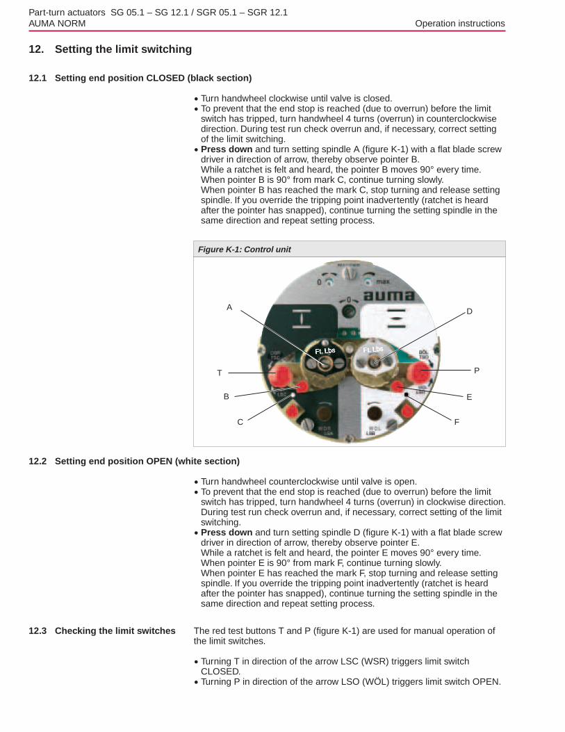
12.1 Setting end position CLOSED (black section).Turn handwheel clockwise until valve is closed..To prevent that the end stop is reached (due to overrun) before the limitswitch has tripped, turn handwheel 4 turns (overrun) in counterclockwisedirection. During test run check overrun and, if necessary, correct settingof the limit switching..Press down and turn setting spindle A (figure K-1) with a flat blade screwdriver in direction of arrow, thereby observe pointer B.While a ratchet is felt and heard, the pointer B moves 90° every time.When pointer B is 90° from mark C, continue turning slowly.When pointer B has reached the mark C, stop turning and release settingspindle. If you override the tripping point inadvertently (ratchet is heardafter the pointer has snapped), continue turning the setting spindle in thesame direction and repeat setting process.
12.2 Setting end position OPEN (white section).Turn handwheel counterclockwise until valve is open..To prevent that the end stop is reached (due to overrun) before the limitswitch has tripped, turn handwheel 4 turns (overrun) in clockwise direction.During test run check overrun and, if necessary, correct setting of the limitswitching..Press down and turn setting spindle D (figure K-1) with a flat blade screwdriver in direction of arrow, thereby observe pointer E.While a ratchet is felt and heard, the pointer E moves 90° every time.When pointer E is 90° from mark F, continue turning slowly.When pointer E has reached the mark F, stop turning and release settingspindle. If you override the tripping point inadvertently (ratchet is heardafter the pointer has snapped), continue turning the setting spindle in thesame direction and repeat setting process.
12.3 Checking the limit switches The red test buttons T and P (figure K-1) are used for manual operation ofthe limit switches..Turning T in direction of the arrow LSC (WSR) triggers limit switch
CLOSED..Turning P in direction of the arrow LSO (WÖL) triggers limit switch OPEN.
Part-turn actuators SG 05.1 – SG 12.1 / SGR 05.1 – SGR 12.1AUMA NORM Operation instructions
Figure K-1: Control unit
A
T
B
C
D
P
E
F

13. Setting the DUO limit switching (option)
Any application can be switched on or off via the two intermediate positionswitches.
For setting, the switching point (intermediate position) mustbe approached from the same direction as afterwards inelectrical operation.
13.1 Setting direction CLOSE (black section).Move valve to desired intermediate position..Press down and turn setting spindle G (figure K-2) with a flat blade screwdriver(5 mm) in direction of arrow, while observing pointer H.While a ratchet is felt and heard, the pointer H moves 90° every time.When pointer H is 90° from mark C, continue turning slowly.When pointer H has reached the mark C, stop turning and release settingspindle. If you override the tripping point inadvertently (ratchet is heardafter the pointer has snapped), continue turning the setting spindle in thesame direction and repeat setting process.
13.2 Setting direction OPEN(white section) .Move valve to desired intermediate position..Press down and turn setting spindle K (figure K-2) with a flat blade screw
driver in direction of arrow, while observing pointer L.While a ratchet is felt and heard, the pointer L moves 90° every time.When pointer L is 90° from mark F, continue turning slowly.When pointer L has reached the mark F, stop turning and release settingspindle. If you override the tripping point inadvertently (ratchet is heardafter the pointer has snapped), continue turning the setting spindle in thesame direction and repeat setting process.
13.3 Checking the DUOlimit switches
The red test buttons T and P (figure K-1) are used for manual operation of theDUO limit switches..Turning T in direction of the arrow TSC (DSR) triggers DUO limit switch CLOSED.
The torque switch CLOSED is actuated at the same time..Turning P in direction of the arrow TSO (DOEL) triggers DUO limit switch OPEN.The torque switch OPEN is actuated at the same time.
Part-turn actuators SG 05.1 – SG 12.1 / SGR 05.1 – SGR 12.1Operation instructions AUMA NORM
Figure K-2: Control unit
G
T
H
C
K
P
L
F
14. Setting the torque switching
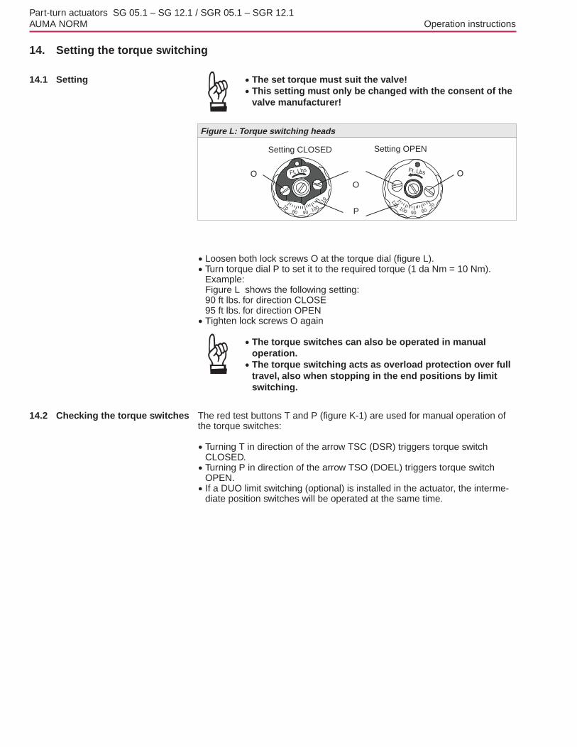
14.1 Setting .The set torque must suit the valve!.This setting must only be changed with the consent of thevalve manufacturer!
.Loosen both lock screws O at the torque dial (figure L)..Turn torque dial P to set it to the required torque (1 da Nm = 10 Nm).Example:Figure L shows the following setting:90 ft lbs. for direction CLOSE95 ft lbs. for direction OPEN.Tighten lock screws O again.The torque switches can also be operated in manual
operation..The torque switching acts as overload protection over fulltravel, also when stopping in the end positions by limitswitching.
14.2 Checking the torque switches The red test buttons T and P (figure K-1) are used for manual operation ofthe torque switches:.Turning T in direction of the arrow TSC (DSR) triggers torque switch
CLOSED..Turning P in direction of the arrow TSO (DOEL) triggers torque switchOPEN.. If a DUO limit switching (optional) is installed in the actuator, the interme-diate position switches will be operated at the same time.
Part-turn actuators SG 05.1 – SG 12.1 / SGR 05.1 – SGR 12.1AUMA NORM Operation instructions
Ft. Lbs Ft. Lbs
7080 100
110
90
110
100 8070
90
Figure L: Torque switching heads
Setting CLOSED Setting OPEN
O O
P
O
15. Test run
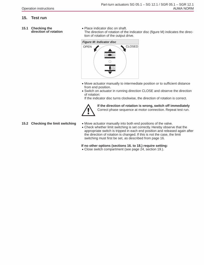
15.1 Checking thedirection of rotation
.Place indicator disc on shaft.The direction of rotation of the indicator disc (figure M) indicates the direc-tion of rotation of the output drive.
.Move actuator manually to intermediate position or to sufficient distancefrom end position..Switch on actuator in running direction CLOSE and observe the directionof rotation:If the indicator disc turns clockwise, the direction of rotation is correct.
If the direction of rotation is wrong, switch off immediatelyCorrect phase sequence at motor connection. Repeat test run.
15.2 Checking the limit switching .Move actuator manually into both end positions of the valve..Check whether limit switching is set correctly. Hereby observe that theappropriate switch is tripped in each end position and released again afterthe direction of rotation is changed. If this is not the case, the limitswitching must first be set, as described from page 16.
If no other options (sections 16. to 18.) require setting:.Close switch compartment (see page 24, section 19.).
Part-turn actuators SG 05.1 – SG 12.1 / SGR 05.1 – SGR 12.1Operation instructions AUMA NORM
Figure M: Indicator disc
OPEN CLOSED

16. Setting the potentiometer (option)
— For remote indication —.Move valve to end position CLOSED..Pull off indicator disc..Turn potentiometer (E2) counterclockwise until stop is felt.End position CLOSED corresponds to 0 %, end position OPEN to 100 %..Turn potentiometer (E2) back a little.
Due to the ratio of the reduction gearings for the positiontransmitter, the complete resistance range is not alwaysutilized for the whole travel. Therefore, an external possi-bility for adjustment (setting potentiometer) must beprovided.
.Perform fine-tuning of the zero point at external setting potentiometer(for remote indication).
Part-turn actuators SG 05.1 – SG 12.1 / SGR 05.1 – SGR 12.1AUMA NORM Operation instructions
Figure N: Control unit
E2

17. Setting the electronic position transmitter RWG (option)
— For remote indication or external control —
After mounting the part-turn actuator to the valve, check setting bymeasuring the output current (see sections 17.1 or 17.2) and re-adjust, ifnecessary.
The position transmitter board (figure P-1) is located under the cover plate(figure P-2).
Part-turn actuators SG 05.1 – SG 12.1 / SGR 05.1 – SGR 12.1Operation instructions AUMA NORM
Terminal plans KMS TP_ _ 4 / _ _ _
3- or 4- wire system
KMS TP _ 4 _ / _ _ _KMS TP _ 5 _ / _ _ _
2-wire systemOutput current Ia 0 – 20 mA, 4 – 20 mA 4 – 20 mAPowersupply
Uv24 V DC, ±15 %
regulated14 V DC + (I x RB),
max. 30 VMax. inputcurrent
I 24 mA at 20 mAoutput current
20 mA
Max. load RB 600 � (Uv - 14 V) / 20 mA
Table 5: Technical data RWG 4020
Figure P-1: Positioner board

17.1 Setting 2-wire system 4 – 20 mA and 3- /4-wire system 0 – 20 mA.Connect voltage to electronic position transmitter..Move valve to end position CLOSED..Pulling off the indicator disc..Connect ammeter for 0 – 20 mA to measuring points (figure P-2).
The circuit (external load) must be connected (observemax. load RB), or the appropriate connections at the termi-nals (refer to wiring diagram) must be jumpered, other-wise no value can be measured.
.Turn potentiometer (E2) counterclockwise until stop is felt..Turn potentiometer (E2) slightly back.
.Turn potentiometer “0” clockwise until output current starts to increase..Turn potentiometer “0” back until the following value is reached:for 3- or 4-wire system: approx. 0.1 mAfor 2-wire system: approx. 4.1 mA.This ensures that the signal remains above the dead and live zero point..Move valve to end position OPEN..Set potentiometer “max.” to end value 20 mA..Approach end position CLOSED again and check minimum value(0.1 mA or 4.1 mA). If necessary, correct the setting.
If the maximum value cannot be reached, the selection of thereduction gearing must be checked.
Part-turn actuators SG 05.1 – SG 12.1 / SGR 05.1 – SGR 12.1AUMA NORM Operation instructions
Figure P-2
“0” (0/4 mA) “max.” (20 mA)
Meas. point (+)0/4 – 20 mA
Meas. point (–)0/4 – 20 mA
Cover plate E2

17.2 Setting 3-/4- wire system 4 – 20 mA.Connect voltage to electronic position transmitter..Move valve to end position CLOSED..Pull off indicator disc..Connect ammeter for 0 – 20 mA to measuring points (figure P-3).
The circuit (external load) must be connected (observemax. load RB), or the appropriate connections at the termi-nals (refer to wiring diagram) must be jumpered, other-wise no value can be measured.
.Turn potentiometer (E2) counterclockwise until stop is felt..Turn potentiometer (E2) slightly back.
.Turn potentiometer “0” clockwise until output current starts to increase..Turn back potentiometer “0” until a residual current of approx. 0.1 mA isreached..Move valve to end position OPEN..Set potentiometer “max.” to end value 16 mA..Move valve to end position CLOSED..Set potentiometer “0” from 0.1 mA to initial value 4 mA.This results in a simultaneous shift of the end value by 4 mA, so that therange is now 4 – 20 mA..Approach both end positions again and check setting. If necessary,correct the setting.
If the maximum value cannot be reached, the selection of thereduction gearing must be checked.
Part-turn actuators SG 05.1 – SG 12.1 / SGR 05.1 – SGR 12.1Operation instructions AUMA NORM
Figure P-3
“0” (0/4 mA) “max.” (20 mA)
Meas. point (+)0/4 – 20 mA
Meas. point (–)0/4 – 20 mA
Cover plate E2

18. Setting the mechanical position indicator
.Place indicator disc on shaft..Move valve to end position CLOSED..Turn lower indicator disc (figure Q-1) until symbol CLOSED is in align-ment with the mark on the cover (figure Q-2)..Move actuator to end position OPEN..Hold lower indicator disc in position and turn upper disc with symbolOPEN until it is in alignment with the mark on the cover.
The indicator disc turns approx. 180° for a swing angle of 90°.
19. Closing the switch compartment
.Clean sealing faces of housing and cover.Check whether O-ring is in good condition..Apply a thin film of non-acidic grease to the sealing faces..Replace cover on switch compartment and fasten bolts evenly crosswise.
Check the part-turn actuator for damage to paint finish. Ifdamage to paint-finish has occurred after mounting, it has tobe touched up to avoid corrosion.
Part-turn actuators SG 05.1 – SG 12.1 / SGR 05.1 – SGR 12.1AUMA NORM Operation instructions
Figure Q-1
Indicator disc
Figure Q-2
Mark

20. Setting the operating time For part-turn actuators with 1-phase AC motors, the operating time can beadjusted.
Work on the electrical system or equipment must only becarried out by a skilled electrician himself or by speciallyinstructed personnel under the control and supervision ofsuch an electrician and in accordance with the applicableelectrical engineering rules.
.Remove motor cover (figure R)..Set required operating time with potentiometer (figure S)..Clean sealing faces of housing and motor cover..Check whether O-ring is in good condition..Apply a thin film of non-acidic grease to the sealing faces..Fit and fasten motor cover.(For enclosure protection IP 68, the motor cover is additionally sealed withthread sealing material.)
Check the part-turn actuator for damage to paint finish. Ifdamage to paint-finish has occurred after mounting, it has tobe touched up to avoid corrosion.
Part-turn actuators SG 05.1 – SG 12.1 / SGR 05.1 – SGR 12.1Operation instructions AUMA NORM
Figure R: Part-turn actuator with 1-phase AC motor
Motor cover
STELLZEITOPERATING TIME
Z 026.161
Figure S: Setting the operating timeOperating timepotentiometer
SG 05.1 5.6 to 45 secondsSG 07.1 11 to 90 secondsSG 10.1 11 to 90 secondsSG 12.1 22 to 180 seconds
Table 6: Operating times for 90°
21. Enclosure protection IP 68 (option)
Definition According to EN 60 259, the conditions for meeting the requirements ofenclosure protection IP 68 are to be agreed between manufacturer anduser.AUMA actuators and controls in enclosure protection IP 68 meet thefollowing requirements according to AUMA:.Duration of submersion in water max. 72 hours.Head of water max. 6 m.Up to 10 operations during submersion.Modulating duty is not possible during submersion
Enclosure protection IP 68 refers to the interior of the actuators (motor,gearing, switch compartment, controls, and terminal compartment).
Inspection AUMA actuators and controls in enclosure protection IP 68 undergo aroutine testing for tightness in the factory.
Cable glands .For the entries of the motor and control cables, appropriate cable glandsin enclosure protection IP 68 must be used. The size of the cable glandsmust be suitable for the outside diameter of the cables, refer to recommen-dations of the cable gland manufacturers..As standard, actuators and controls are delivered without cable glands.For delivery, the threads are sealed with plugs in the factory..When ordered, cable glands can also be supplied by AUMA at an addi-tional charge. For this, it is necessary to state the outside diameter of thecables..The cable glands must be sealed against the housing at the thread with anO-ring.. It is recommended to additionally apply a liquid sealing material (Loctite orsimilar).
Commissioning When commissioning, the following should be observed:.Sealing faces of housing and covers must be clean.O-rings of the covers must not be damaged.A thin film of non-acidic grease should be applied to sealing faces.Covers should be tightened evenly and firmly
After submersion .Check actuator.. In case of ingress of water, dry actuator correctly and check for properfunction.
Part-turn actuators SG 05.1 – SG 12.1 / SGR 05.1 – SGR 12.1AUMA NORM Operation instructions

22. Maintenance After maintenance, check part-turn actuator for damage to paint finish. Ifdamage to paint-finish has occurred after mounting, it has to be touched upto avoid corrosion. Original paint in small quantities can be supplied byAUMA.
AUMA part-turn actuators require very little maintenance.Precondition for reliable service is correct commissioning.
Seals made of elastomers are subject to ageing and must therefore regu-larly be checked and, if necessary, be exchanged.
It is also very important that the O-rings at the covers are placed correctlyand cable glands tightened firmly to prevent ingress of dirt or water.
We recommend additionally:. If rarely operated, perform a test run about every 6 months. This ensuresthat the actuator is always ready to operate..Approximately six months after commissioning and then every year checkbolts between part-turn actuator and valve/gearbox for tightness. Ifrequired, tighten applying the torques given in table 1, page 9.
23. Lubrication AUMA part-turn actuators are filled with grease for lifetime.A change of grease or re-lubrication is not necessary.
Part-turn actuators SG 05.1 – SG 12.1 / SGR 05.1 – SGR 12.1Operation instructions AUMA NORM

24. Disposal and recyclingAUMA actuators have an extremely long lifetime. However, they have to bereplaced at one point in time.The actuators have a modular design and may therefore easily be disas-sembled, separated, and sorted according to materials, i.e.:.electronic scrap.various metals.plastics.greases and oils
The following generally applies:.Collect greases and oils during disassembly. As a rule, these substancesare hazardous to water and must not be released into the environment..Arrange for controlled waste disposal of the disassembled material or forseparate recycling according to materials...Observe the regional regulations for waste disposal.
25. Service AUMA offers extensive services such as maintenance and inspection foractuators. The AUMA service department can be reached at:phone: 724-743-AUMA (2862)Fax: 724-743-7411email: [email protected] or www.auma.com.
Part-turn actuators SG 05.1 – SG 12.1 / SGR 05.1 – SGR 12.1AUMA NORM Operation instructions

26. Spare parts list part-turn actuator SG(R) 05.1 – SG(R) 12.1 with plug/socketconnector
Part-turn actuators SG 05.1 – SG 12.1 / SGR 05.1 – SGR 12.1Operation instructions AUMA NORM
Sam
ple
nam
epl
ate
-A
ctua
tor
type
-C
omm
issi
onnu
mbe
r-
Wor
ksnu
mbe
r-
Enc
losu
repr
otec
tion/
outp
utsp
eed
Torq
uera
nge
inC
LOS
ED
/O
PE
N-
Lubr
ican
t-
Tem
pera
ture
rang
e
aumaCC
AU
MA
AC
TU
ATO
RS
INC
.P
ITT
SB
UR
GH
PAU
SA
SG
07.1
-F7
Com
.No.
:130
9533
No:
3302
MD
1930
2n:
11rp
mT
open
:120
-300
Nm
Tcl
ose
120-
300N
mLu
br.:
F1
Tem
p.:-
25°C
/+80
°C
152.
2
152.
1
153.
2
153.
1
153.
3
153.
0
39.2
.438
.2.4
39.2
.3
39.2
.2
38.2
.338
.2.2
39.2
39.0
38.0
S1
/ S2
S1
/ S2
1610
.0
2.4
2.0
S2
4.0
S2
S2
5.0
14
36.0
36.3
.236
.3.4
36.3
.1
1 S2
17.0
S2
21.0
36.2
36.6
34.2
2
41
32.0
S1
/ S2
35.0
36.1
036
.5
3.0
S2
29.0
40.0
43
40.0
40.4
3
34.2
334
.24
S1
/ S2
3-ph
AC
34.7
34.8
34.9
34.0
1-ph
AC
36.1

Note:Please state type and commission no. of the actuator (see name plate) when ordering spare parts. Delivered spareparts may slightly vary from the representation in these instructions.
* not included in basic equipment Motor plug; motor directly wired to pin carrier (no. 52.0).
Part-turn actuators SG 05.1 – SG 12.1 / SGR 05.1 – SGR 12.1AUMA NORM Operation instructions
No. Type Designation
1 E Housing
2.0 B Worm shaft assly.
2.4 E End stop nut (included in sub-assembly 2.0)
3.0 B Manual drive worm assly.
4.0 B Worm wheel
5.0 B Mounting flange assly.
10.0 B Limit stop housing assly.
14 E Coupling
16 E Cap
17.0 B Torque finger assly.
21.0 B Limit drive finger assly.
29.0 B Manual drive bearing assly.
32.0 B Planetary gearing assly.
34.0 B Motor assly.
34.22 BMotor plug pin carrier(without pins)
34.23 B Pin for motor
34.24 B Pin for thermoswitch
34.7 B Motor brake
34.8 B Motor electronic board
34.9 B Cover plate
35.0 B Cover assly.
36.0 B Control unit assly. (without switches)
36.1 B Torque switching head
36.2 B Heater
36.3.1 B Stud bolt for switches
36.3.2 BSwitch for limit/torque switching(including pins at wires)
36.3.4 E Spacer
No. Type Designation
36.5 B Mechanical position indicator
36.6* BBlinker transmitter including pins at wires(without impulse disc and insulation plate)
36.10 E Cover plate
38.0 B Pin carrier (without pins)
38.2.2 B Pin for motor
38.2.3 B Pin for controls
38.2.4 B Wire for protective earth
39.0 B Plug cover assly.
39.2 BSocket carrier(complete with sockets)
39.2.2 BSocket for motor(included in sub-assembly 39.2)
39.2.3 BSocket for control(included in sub-assembly 39.2)
39.2.4 BSocket for protective earth(included in sub-assembly 39.2)
40 B Handwheel assly.
40.043 E Cap assly.
40.43 B Ball handle assly.
41 B Motor plug, socket assly.
152.1* B Potentiometer (without slip clutch)
152.2* B Slip clutch for potentiometer
153.0* B Electronic position transmitter (RWG)
153.1* B Potentiometer for RWG (without slip clutch)
153.2* B Slip clutch for RWG
153.3* B Electronic board RWG
S 1 S Seal kit (small)
S 2 S Seal kit (large)

Part-turn actuators SG 05.1 – SG 12.1 / SGR 05.1 – SGR 12.1Operation instructions AUMA NORM
IndexAAmbient temperature 6
CCorrosion protection 7,27
DDelay time 10DUO limit switching 17
EElectrical connection 10Electronic position transmitterRWG 21
2-wire system 223-/4-wire system 23
Enclosure protection IP 68 26End stops 12
SG on ball valves 13SG on butterfly valves 12
FFitting the ball handle 7
HHandwheel 8Heater 11
IIndicator disc 24
LLimit switches 11Limit switching 16,17Lubrication 27
MMaintenance 4Manual operation 8Mechanical position indicator 24Motor protection 11Mounting to valve 9
NName plate 29
OOperating time 25
PPackaging 7Position indicator 24Position transmitter RWG 21Potentiometer 20PTC thermistors 11
RRemote indication 20,21
SSafety instructions 4Service 28Spare parts list
Part-turn actuator 29Storage 7Swing angle 14
TTandem switches 11Technical data 5Test run 19Thermoswitches 11Torque setting 18Transport 7Tripping torque 18Type of duty 5

Y000 234/035/en/1 05
North American Sales and Service:
US Headquarters and Factory:AUMA Actuators, Inc.100 Southpointe Blvd.Canonsburg PA 15317Tel: 724-743-AUMA (2862)Fax: 724-743-4711email: [email protected]
Regional Offices:Northeast (Maryland and New York)Southeast (South Carolina)Midwest (Illinois)Midwest (Kansas)Houston (Texas)West Coast (Northern and Southern California)
Representatives and DistributorsAnchorageAtlantaBaltimoreBaton RougeBirminghamBostonCharlotteChicagoCincinatiCorpus ChristiDallasDenverDetroitHawaiiHoustonIndianapolisKansas CityLos AngelesMexicali (Mexico)Mexico CityMilwaukeeMinneapolisMontanaMonterrey (Mexico)New YorkOmahaOrlandoPhiladelphiaPhoenixPittsburghRochesterSalt Lake CitySan DiegoSan FranciscoSan JuanSeattleSt. LouisTorontoTulsa
International Headquarters:AUMA Riester GmbH & Co. KGMüllheim/ Germanywww.auma.com
International Sales and Service:South America:ArgentinaBrazilChileColombiaPeruVenezuela
Europe:AustriaBeneluxCzech RepublicDenmarkFinlandFranceGreeceHungaryItalyNorwayPolandPortugalRussiaSpainSwedenSwitzerlandTurkeyUkraineUnited Kingdom
AfricaEgyptSouth Africa
Asia, AustraliaAustraliaChinaHong KongIndiaJapanKoreaKuwaitOmanQatarSingaporeTaiwanThailandUAE
For the name and phone number of the officenearest you, call us at 724-743-2862 or visit ourwebsite at www.auma-usa.com/saleserv.htm2005-06-27