electric distribution & controls - usbid switch catalog... · f7 g3 - g5 g3 g3 f2 a20 a23 a2...
TRANSCRIPT

Electric Distribution & Controls
Switch Catalog

2 EATON CORPORATION Aerospace TF300-5 June, 2004
Making the Best Better
Traditional aerospace compo-nent suppliers are being askedto assume even greater levelsof responsibility. One trend isthat component manufacturersare being asked to increasetheir subsystem integrationcapability to better serve theconsolidating global Tier 1Systems Integrators andAirframe Manufacturers.Component suppliers will beexpected to bring more valueto fewer, more demanding cus-tomers. Redefining EatonAerospace's ElectricDistribution and Controls valueproposition is essential tomeeting those expectations.
To enhance Eaton Aerospace'sposition in the market, Eatonredefined its go-to-market strat-egy in the third quarter of2003. Eaton Aerospace formedthe Electric Distribution andControls product family, whichcombined the complimentaryproduct portfolios and cus-tomers of the Cockpit Controls(Costa Mesa, CA) and Powerand Load Management(Sarasota, FL) business units.The synergy of the newlyformed product family groupaffords Eaton AerospaceElectric Distribution andControls greater engineeringscale and supplier purchasingpower, and an opportunity to"Lean" both Support Functionsand Operations. For the cus-tomer and distribution channelpartner, this translates into anincreased focus on growing thebusiness through new productdevelopments, a commitmentto Operational Excellence, anddriving a new culture focusedon customer satisfaction. Thecombined engineering, opera-tional, and test competenciespermit Electric Distribution andControls to develop a fully inte-
grated cockpit mounted over-head panel utilizing the compo-nents of the existing productportfolio.
Eaton's portfolio of aerospaceand commercial switch prod-ucts includes thousands of dif-ferent aerospace switches andcommercial switches withcomplementary hardware andaccessories. These deviceshave a broad range of applica-tions ranging from commercialaviation to military fighters,from construction vehicles tomass transit rail, and fromarmored vehicles to the SpaceShuttle. With such a broadapplication range, EatonElectric Distribution andControls has the experience totransfer this aerospace switchtechnology to other demandingenvironments which requirespecific performance levels andsealing requirements due toharsh operating conditions.
Each switch design is opti-mized for the customer's par-ticular application by using theappropriate switch mechanism.Options include contactless,extended-life, snap-action,tapered, and limit switch ver-sions. Additionally, the forma-tion of the Electric Distributionand Controls product family hasallowed Eaton Aerospace tobuild on its long pedigree withcomplementary aerospaceproducts, including illuminatedpushbutton switches, pilot con-trols, displays, and keyboards.This broad aerospace productportfolio allows Eaton to posi-tion itself as a supplier ofproven aerospace componentsas well as a provider of inte-grated subsystem solutions.Eaton Aerospace ElectricDistribution and Controls hassuccessfully marketed subsys-
tems in both the aerospaceand agriculture industries.These Capabilities and
Product Articles are featuredon pages 6-9.
Eaton Aerospace is recognizedas a leader in aerospaceswitching components. Theseswitches will be combined withperformance rated relays, con-tactors, remote control circuitbreakers, and thermal circuit breakers to bring more value to our end customers. The rede-fined product portfolio providesTier 1 System Integrators andAirframe Manufacturers agreater array of product to pur-chase from a single qualifiedsupplier that is certified to thestringent requirements of theinternationally recognizedQuality Standard AS9100. The extensive product portfolio and quality certification alsoensures our new and existingcustomers improved levels ofservice and sales opportunitieswith the product performanceand reliability they are accus-tomed to. At Eaton Aerospace,we are making the best in theindustry even better.

EATON CORPORATION Aerospace TF300-5 June, 2004 3
Switch Catalog
Table of ContentsDescriptive IndexFast Information FinderPart Number to Page Index
Capabilities and Featured Products
Organizational CapabilitiesFeatured Product ArticlesNotes
Toggle Switches
Pushbutton Switches
Rocker Switches
Precision Snap Action Switches
Sealed Limit Switches
Switch Guards & Shields
Accessories
Reference
3
4
5
5
6 - 7
8 - 9
10
A1 - A76
B1 - B26
C1 - C32
D1 - D6
E1 - E4
F1 - F8
G1 - G8
H1 - H12
Table of Contents
Toggle Switches
Pushbutton Switches
Rocker Switches
Precision Snap Action Switches
Sealed Limit Switches
Accessories
Reference
Capabilities and Featured Products
Switch Guards & Shields

4 EATON CORPORATION Aerospace TF300-5 June, 2004
Descriptive Index
Accessories G1 - G5
Cross Reference
Part Number to Page Index 5
Military P/N to Eaton P/N H2 - H7
Test Requirements per MIL Specs H8 - H9
Glossary of Terms H10 - H12
Capabilities 6 - 7
EMI/RFI Shielded Pushbutton Switches B14 - B19
Environmentally Sealed Switches
Environmentally Sealed Rocker Switches C-9 - C-31
Environmentally Sealed Toggle Switches A2 - A34
Limit Switches E1 - E3
Hermetic Switches E4
MIL-S-3950 Environmentally Sealed A20 - A34
Toggle Switches
Miniature Switches
MIL-S-8834 Miniature Positive Action A48 - A62
Four-Pole Miniature Positive Action Toggle A63 - A66
Miniature Switches with Integrated Wire A60 - A62
Termination System (IWTS) Miniature Integral Toggle Switches A67
Precision Snap Action Switches
Basic Snap Switches D2 - D4
Roller, Straight, and Leaf Actuator D5
Pushbutton Switches
Illuminated Pushbutton Switches B20
Sub-Miniature Pushbutton Switches B18 - B19
Pistol Grip Pushbutton Switches B21 - B23
Special Designed Pushbuttons B24 - B25
Standard Pushbutton Switches B2 - B14
Uniform Panel Appearance (UPA) B15 - B17
Pushbutton Switches
Rocker Switches
Econo Switch Sealed Rocker Switches C9 - C18
"Illuminater" Series Rocker Switches C2- C8
Removable Button (RB Series) C9 - C12
Rocker Switches
Switch Guards & Shields F1 - F8
Toggle Switches
Designerline Toggle Switches A8 -A10
Environmentally Sealed Toggle Switches A2 - A34, A38 - A47
Environmentally Sealed Toggle Switches A27 - A34, A60 -A62
with Integrated Wire Terminal Systems (IWTS)Environmentally Sealed Positive A38 - A47
Action SwitchesHigh Capacity Toggle Switches A68 - A69
Integral Toggle Switches A67
MIL-S-8805 Toggle Switches A35 - A37
MIL-S-3950 Toggle Switches A20 - A34
MIL-S-8834 Toggle Switches A38 - A62
Multi-Circuit Toggle Switches A35 - A37
Econoswitch Line A11 - A19
EATON CORPORATION Aerospace TF300-5 June, 2004 5
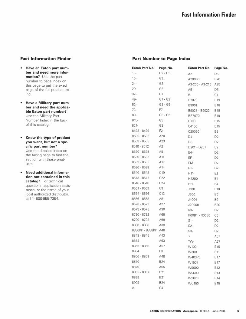
Fast Information Finder Part Number to Page Index
Fast Information Finder
• Have an Eaton part num-
ber and need more infor-
mation? Use the part number to page index on this page to get the exact page of the full product list-ing.
• Have a Military part num-
ber and need the applica-
ble Eaton part number?
Use the Military Part Number Index in the back of this catalog.
• Know the type of product
you want, but not a spe-
cific part number?
Use the detailed index on the facing page to find the section with those prod-ucts.
• Need additional informa-
tion not contained in this
catalog? For technical questions, application assis-tance, or the name of your local authorized distributor, call 1- 800-955-7354.
Eaton Part No.
15-
16-
24-
29-
32-
49-
52-
73-
80-
815-
821-
8492 - 8499
8500 - 8502
8503 - 8505
8510 - 8512
8520 - 8528
8530 - 8532
8533 - 8535
8536 - 8538
8540 - 8542
8543 - 8545
8546 - 8548
8551 - 8553
8554 - 8556
8566 - 8568
8570 - 8572
8573 - 8575
8780 - 8782
8790 - 8792
8836 - 8838
8836KP - 8838KP
8843 - 8845
8854
8855 - 8856
8864
8866 - 8869
8870
8879
8895 - 8897
8899
8909
A-
Page No.
G2 - G3
G3
G2
G2
G1
G1 - G2
G3 - G5
F7
G3 - G5
G3
G3
F2
A20
A23
A2
A5
A11
A17
A14
C19
C22
C24
C9
C13
A8
A27
A30
A68
A68
A38
A46
A43
A63
A57
F8
A48
B24
A65
B21
B21
B24
C4
Page No.
D5
B20
A35
D5
C4
B19
B18
B18
B19
B15
B15
B8
D2
D2
B2
D2
D2
D2
D2
E2
B4
E4
B10
B6
B9
B20
D2
C5
D2
D2
D2
A67
A67
B15
B11
B17
B17
B12
B13
B14
B15
Eaton Part No.
A2-
A20000
A3-200 - A3-215
A5-
B-
B7070
B9001
B9021 - B9022
BR7070
C100
C4100
C20050
D4-
D8-
D201 - D207
E4-
EF-
EM-
G3-
H11-
H2200
HH-
J100
J300
J4004
J20000
K3-
R00B1 - R00B5
S1-
S2-
S3-
T-
TW-
W100
W300
W403P6
W1501
W9000
W9600
W9623
WC150
6 EATON CORPORATION Aerospace TF300-5 June, 2004
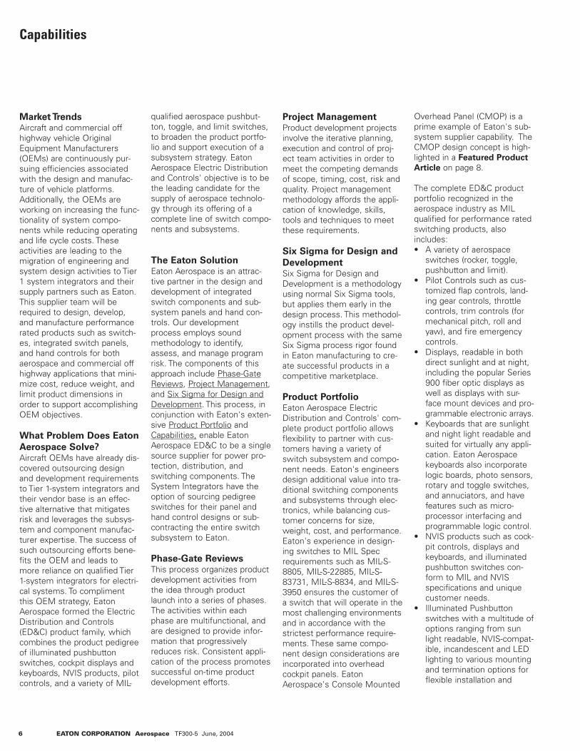
Capabilities
Market TrendsAircraft and commercial offhighway vehicle OriginalEquipment Manufacturers(OEMs) are continuously pur-suing efficiencies associatedwith the design and manufac-ture of vehicle platforms.Additionally, the OEMs areworking on increasing the func-tionality of system compo-nents while reducing operatingand life cycle costs. Theseactivities are leading to themigration of engineering andsystem design activities to Tier1 system integrators and theirsupply partners such as Eaton.This supplier team will berequired to design, develop,and manufacture performancerated products such as switch-es, integrated switch panels,and hand controls for bothaerospace and commercial offhighway applications that mini-mize cost, reduce weight, andlimit product dimensions inorder to support accomplishingOEM objectives.
What Problem Does Eaton
Aerospace Solve?Aircraft OEMs have already dis-covered outsourcing designand development requirementsto Tier 1-system integrators andtheir vendor base is an effec-tive alternative that mitigatesrisk and leverages the subsys-tem and component manufac-turer expertise. The success ofsuch outsourcing efforts bene-fits the OEM and leads tomore reliance on qualified Tier1-system integrators for electri-cal systems. To complimentthis OEM strategy, EatonAerospace formed the ElectricDistribution and Controls(ED&C) product family, whichcombines the product pedigreeof illuminated pushbuttonswitches, cockpit displays andkeyboards, NVIS products, pilotcontrols, and a variety of MIL-
qualified aerospace pushbut-ton, toggle, and limit switches,to broaden the product portfo-lio and support execution of asubsystem strategy. EatonAerospace Electric Distributionand Controls' objective is to bethe leading candidate for thesupply of aerospace technolo-gy through its offering of acomplete line of switch compo-nents and subsystems.
The Eaton SolutionEaton Aerospace is an attrac-tive partner in the design anddevelopment of integratedswitch components and sub-system panels and hand con-trols. Our developmentprocess employs soundmethodology to identify,assess, and manage programrisk. The components of thisapproach include Phase-GateReviews, Project Management,and Six Sigma for Design andDevelopment. This process, inconjunction with Eaton's exten-sive Product Portfolio andCapabilities, enable EatonAerospace ED&C to be a singlesource supplier for power pro-tection, distribution, andswitching components. TheSystem Integrators have theoption of sourcing pedigreeswitches for their panel andhand control designs or sub-contracting the entire switchsubsystem to Eaton.
Phase-Gate ReviewsThis process organizes productdevelopment activities fromthe idea through productlaunch into a series of phases.The activities within eachphase are multifunctional, andare designed to provide infor-mation that progressivelyreduces risk. Consistent appli-cation of the process promotessuccessful on-time productdevelopment efforts.
Project ManagementProduct development projectsinvolve the iterative planning,execution and control of proj-ect team activities in order tomeet the competing demandsof scope, timing, cost, risk andquality. Project managementmethodology affords the appli-cation of knowledge, skills,tools and techniques to meetthese requirements.
Six Sigma for Design and
DevelopmentSix Sigma for Design andDevelopment is a methodologyusing normal Six Sigma tools,but applies them early in thedesign process. This methodol-ogy instills the product devel-opment process with the sameSix Sigma process rigor foundin Eaton manufacturing to cre-ate successful products in acompetitive marketplace.
Product PortfolioEaton Aerospace ElectricDistribution and Controls' com-plete product portfolio allowsflexibility to partner with cus-tomers having a variety ofswitch subsystem and compo-nent needs. Eaton's engineersdesign additional value into tra-ditional switching componentsand subsystems through elec-tronics, while balancing cus-tomer concerns for size,weight, cost, and performance.Eaton's experience in design-ing switches to MIL Specrequirements such as MIL-S-8805, MIL-S-22885, MIL-S-83731, MIL-S-8834, and MIL-S-3950 ensures the customer ofa switch that will operate in themost challenging environmentsand in accordance with thestrictest performance require-ments. These same compo-nent design considerations areincorporated into overheadcockpit panels. EatonAerospace's Console Mounted
Overhead Panel (CMOP) is aprime example of Eaton's sub-system supplier capability. TheCMOP design concept is high-lighted in a Featured Product
Article on page 8.
The complete ED&C productportfolio recognized in theaerospace industry as MILqualified for performance ratedswitching products, alsoincludes:• A variety of aerospace
switches (rocker, toggle, pushbutton and limit).
• Pilot Controls such as cus-tomized flap controls, land-ing gear controls, throttle controls, trim controls (for mechanical pitch, roll and yaw), and fire emergency controls.
• Displays, readable in both direct sunlight and at night, including the popular Series 900 fiber optic displays as well as displays with sur-face mount devices and pro-grammable electronic arrays.
• Keyboards that are sunlight and night light readable and suited for virtually any appli-cation. Eaton Aerospace keyboards also incorporate logic boards, photo sensors,rotary and toggle switches, and annuciators, and have features such as micro-processor interfacing and programmable logic control.
• NVIS products such as cock-pit controls, displays and keyboards, and illuminated pushbutton switches con-form to MIL and NVIS specifications and unique customer needs.
• Illuminated Pushbutton switches with a multitude ofoptions ranging from sunlight readable, NVIS-compat-ible, incandescent and LED lighting to various mounting and termination options for flexible installation and

EATON CORPORATION Aerospace TF300-5 June, 2004 7
retrofit applications. Eaton Aerospace's most popular, Series 584, is qualified to MIL-S-22885/110.
• Electro-mechanical thermal circuit breakers (0.5 to 300 amperes) - single phase or three phase thermally actu-ated devices offered in con-ventional design or with integrated Arc Fault Circuit Interrupt technology
• Remote Control Circuit Breakers (5 to 125 amperes)- single phase or three-phase devices sold sepa-rately or as a subsystem when combined with a nec-essary indicator control unit (0.5 ampere circuit breaker).
• Electro-mechanical Remote Power Controllers (125 to 200 amperes) - single-phasedevices sold separately or as a subsystem when com-bined with a necessary indi-cator control unit (0.5 ampere circuit breaker).
• Smart Contactors with cur-rent sensing protection and Arc Fault Circuit Interrupt technology
• 28 VDC Contactors (50 to 1000 amperes)
• 270 VDC Contactors (25 to 350 amperes)
• 115/230 VAC 400 Hertz Contactors (30 to 430 amperes)
• 750 VDC Contactors (100 to600 amperes)
Eaton Capabilities• Proven excellence in com-
ponent and subsystem design, development, test-ing, qualification, and pro-duction for both military andcommercial aerospace appli-cations.
• A manufacturing organiza-tion that emphasizes cus-tomer satisfaction by focus-ing on cost, quality, and delivery of the product port-folio.
• Altitude / temperature test-ing chamber simulating alti-tude to 80,000 feet and temperatures from -65°C to 125°C.
• Test capabilities of 115/200 VAC 400hz to 3600 amps, 28 VDC to 10,000 amps, 270/350/475 VDC to 1,500 amps.
• Environmental tests for Sand and Dust, Shock, and Vibration.
• Latest CAD/CAM finite ele-ment analysis and stere-olithographic techniques, and PRO E design.
• Model Shop flexibility to respond to design changes and rapid turn around of pro-totypes.
The Eaton DifferenceThere are a number of switchsuppliers in the aerospace mar-ket. However, few possess thevertical integration needed toengineer and manufacture toboth MIL Spec and OEM cus-tomer specifications to ensureconsistency of quality opera-tion in switches and subsys-tems that include both over-head cockpit panels andergonomic hand controls.
Eaton Aerospace affords itscustomers the following differ-ence:• Strong brand recognition,
customer loyalty, and demonstrated market pres-ence for over 80 years.
• Ability to leverage the com-pany's size, financial strength, and scope to drivesuperior results. Eaton Aerospace has the ability to leverage the engineering resources of a multi-billion dollar company.
• An extensive product portfo-lio that compliments inte-grated subsystem design competency.
• A flat organizational struc-
ture that allows for the opti-mal blend of best value technical approach and test support within budget and schedule constraints.
• Dedicated program man-agers that understand and communicate the "voice of the customer".
• Design software that pro-motes concurrent engineer-ing and the exchange of customer data.
• Co-located engineering, manufacturing, and develop-ment resources promote robust product developmentand product support.
Eaton's unique product portfo-lio, its ability to design andmanufacture components andsubsystems, and customercentric strategy, mitigates therisk associated with new air-craft electrical systems. Eatonis an ideal candidate to consid-er for engineering and manu-facturing collaboration on allfuture commercial, general avi-ation, and military programs.
Capabilities

8 EATON CORPORATION Aerospace TF300-5 June, 2004
CHANGING
AEROSPACE
INDUSTRY
In today's consolidating aero-space industry, Tier 1-SystemIntegrators and AirframeManufacturers desire morevalue from their componentsuppliers. A qualified suppliermust not only have an exten-sive product portfolio, but mustalso display proven subsystemcapabilities. These abilitiesinclude the capacity to design,manufacture, and test cus-tomized switch assemblies thatconsolidate multiple functionsin a single package. Over thepast decade, Eaton AerospaceElectric Distribution andControls (ED&C) has recog-nized this fact, and hasfocused its attention on provid-ing these value-add competen-cies to become the marketleader in integrated control sys-tems. Eaton Aerospace hassupplied customers with thefollowing subassemblies: inte-grated switch panels, cockpitmounted overhead panels,multi-functional hand controls,and electronic shifters.
INTEGRATEDCONTROL PANELS
Many aircraft manufacturersare currently purchasing dis-crete components such asswitches, indicators, lighting,and circuit boards from compo-nent suppliers, and thenassembling these componentsas subsystems in-house. Thisprocess is sub-optimal inensuring a low cost, highly reli-able subsystem. With innova-tive technology and outstand-ing customer relations, EatonAerospace is positioned to fillthis current market void as apremier one-stop, subsystemsupplier.
The introduction of the EatonIntegrated Switch Panel designallows Eaton Aerospace ED&Cto be a key supplier in the sub-system market. The IntegratedPanel provides the next gener-ation of cockpit controls,whereby conventional multi-pole switch and indicator func-tions are incorporated into aprinted circuit board with alight plate. Eaton's custompanels with imbedded elec-tronics can significantly lowerinstallation costs and times,reduce weight, and raise relia-bility for the end customer.Furthermore, an EatonIntegrated Panel can reducepanel depth (by 66%) andweight (by 50%) from tradition-al panel designs, allowingOEMs to realize additional fuelsavings and increased carryingcapacity.
The core of this low profile(15.5 mm thick) IntegratedSwitch Panel is a Type 7 Light-Emitting Diode (LED) MountingPanel and single or multiple
Printed Circuit Boards (PCBs)that contain LED current regu-lation. Front-load, miniature,snap-in avionics switches aretypically used for easy mainte-nance, and can be combinedwith snap-in switch guards thatare locked in place by theswitch. Additional packagingoptions can include "Smart”electronics that incorporatemicroprocessor logic, built-intest capability, and bus com-munications.
Cockpit Mounted
Overhead Panel (CMOP)
With Fire Control
ED&C supplies advanced over-head panels to aircraft manu-facturers who require high per-formance cockpit panels incor-porating several hundredswitches and indicators withARINC 429 bus communica-tion. Customers can alsochoose features such as logicand power supply redundancy,as well as LED lighting for bothpanel and indication. This inte-gration of lighting, circuitry, andcomponents leads to improvedsystem reliability and lowMTBF/MTBR.
Additionally, Eaton Aerospace'stoggle switch product line
allows customers to cut costsby using our proven toggleswitches, that work with abroad range of current ratingsfrom logic level (25A) to powerloads (5A), without changingcontact material. A variety oflever style Actuator and termi-nal fittings can be used to fur-ther meet customer needs.Other features on the CMOPinclude: Direct PCB MountingSolder, Plug-in Contacts, NVISFilters, Standard Light Plates,Removable Capsules,Removable Mini-switches, andContactless Switches - optionsthat afford the aircraft manufac-turer maximum system flexibility.
Featured Products - Integrated Control Systems

ERGONOMIC HANDCONTROLS
Eaton Aerospace has displayedtheir subsystem capability withintegrated hand controls forboth the commercial off high-way and aerospace industries.These integrated hand controlscombine the functionality of agrip and joystick to provide asingular device for man-machine interface that canendure long-term exposure toharsh environments.
To develop and manufacturethese hand controls for uniquecustomer applications, EatonAerospace ED&C utilizes a vari-ety of materials, platings, fin-ishings, and assembly andmolding techniques using in-house resources. In addition,these capabilities can be com-bined with Eaton Aerospace'spatented contactless switchdevelopment and a variety ofswitch assemblies and harnessconfigurations to further cus-tomize the specific hand con-trol design to the end cus-tomer.
Multi-Function Handles
Recently, Eaton AerospaceED&C developed a multi-func-tion handle to be used on agri-cultural combines. The projectprovided Eaton Aerospace thechance to gain additional expe-rience in the development ofoperator controls.
Eaton Aerospace's engineeringstaff collaboratively works withits customers to optimize thedesign solution while minimiz-ing design cycle time. Thisdesign philosophy ensurescustom design and assemblymethods that minimize thecost of the handle.
As a result of customer part-nerships such as this, EatonAerospace has added severalkey features to its valued handcontrols - ergonomicallydesigned handles, adjustable 'wrist rests' for operator com-fort, soft feel paint applied tomolded handles, and handlesthat can rotate (with adjustabletorque) about the mountingtube.
Electronic Shifters
Eaton Aerospace ED&C hassupplied electronic shifter con-trol assemblies to various offhighway customers for applica-tion vehicles such as wheelloaders and motorgraders. Inaddition, other control designshave included steering andtransmission integrated con-trols. These shifter controlsintegrate both speed and direc-tion control functionalities.Specially designed long-lifeswitch contacts provide evenmore value for the end cus-tomer.
As a result of these productdevelopments, EatonAerospace is positioned toleverage its integrated handcontrol competencies andapply them to innovativedesigns in the commercial,general aviation, and militaryaerospace industries.
EATON CORPORATION Aerospace TF300-5 June, 2004 9
Featured Products - Integrated Control Systems

10 EATON CORPORATION Aerospace TF300-5 June, 2004
Notes

EATON CORPORATION Aerospace TF300-5 June, 2004 A1
Section AToggle Switches Index
Index A1
Industrial - Environmentally Sealed Switches A2 – A10
• Watertight seal per MIL-STD-108• Ratings at 28VDC and 115VAC 60/400Hz• One, two and four pole configurations• Toggle, lever lock and designerline Actuator• Positive detent action• Multi-circuit variations offered
Econoswitch - Environmentally Sealed Switches A11 – A19
• Watertight seal per MIL-STD-108• Ratings at 28VDC and 115VAC 60/400Hz• One, two and four pole configurations• Patented base compression seal• Toggle, lever lock and designerline Actuator• Terminal variations - screw, spade and solder lug
Military - Environmentally Sealed Switches A20 – A34
• MS approved and QPL listed to MIL-S-3950• One, two and four pole configurations• Terminal variations - screw and IWTS• Toggle and lever lock Actuator• Positive dentent action
Multi-Circuit Switches A35 – A37
• Ratings up to 7 amperes• Two, four, six and eight pole configurations• Lever lock or standard lever Actuator• Double turret terminals• One hold mounting
Environmentally Sealed Positive Action Switches A38 – A47
• Meets MIL-S-8834 requirements• Ratings at 28VDC and 115VAC, 60/400Hz• One, two and four pole configurations• Standard lever and lever lock Actuator• High reliability - Mechanical and electrical• Screw and solder lug
Miniature Positive Action Switches A48 – A66
• MS approved and QPL listed to MIL-S-8834• Rating variation - power to logic levels• One and two pole configuration• Bushing sealed per MIL-S-8834• Non-teasible mechanism• Toggle and lever lock Actuator• Terminal variations - solder lug, printed circuit and IWTS
Miniature Integral Switches A67
• Ratings up to 20 amperes• One and two pole configurations• Choice of terminals• Maintained contacts• One hold mounting
High Capacity Switches A68 – A69
• High current capability at 28VDC and 115VAC 60 Hz• One and three pole arrangements• Positive detent action• Flush mounted• Large toggle Actuator
Ratings and Switch Position Diagrams A70 – A75
*Most items listed in this catalog are standard products and are normally inDistributor Inventory; however, the current inventory status should be checked bycontacting your Eaton Customer Service Representative at 800-955-7354 or yourauthorized Distributor before placing orders.

A2 EATON CORPORATION Aerospace TF300-5 June, 2004
INDUSTRIAL - ENVIRONMENTALLY SEALED SWITCHESSeries - 8510, 8511, 8512 Environmentally Sealed Toggle Switches
8510 8511 8512
No. of Poles
Catalog Number
Type of Operation
1 8510 Maintained 5 20 15 3 15 10Momentary 4 15 10 2 15 7
2 8511 Maintained 7 20 15 4 15 15 Momentary 5 18 10 2 11 84 8512 Maintained 5 20 12 4 15 15 Momentary 4 18 10 2 11 8
115 VAC 60 or 400Hz
Lamp Load
Resistive Load
Inductive Load
28VDCLamp Load
Resistive Load
Inductive Load
CIRCUIT WITH LEVER IN . . . ONE POLE TWO POLE FOUR POLE
Up
Position
Center
Position
Down Position
(Keyway)
ONONONONONON
* ONNONEONOFFON
* ONONONON
* ONONON
* ON
OFFNONENONEOFFOFF*
NONEOFFOFFNONENONEOFFONONONONONONONON
ONOFFONNONENONEON*
ON*
ON*
OFF*
ON*
ON*
NONENONEONON*
ON*
ONON*
ON*
8510K1K9K4K6K8
8510K5K2K7K10K11
8510K3K12K13——————
8511K1K9K4K6K8
8511K5K2K7K10K11
8511K3K12K13
8511K14K15K16
8511K17K18K19
8512K1K9K4K6K8
8512K5K2K7K10K11
8512K3K12K13
8512K15K16K17———
Catalog
NumberCatalog
Number
Catalog
Number
* Momentary contact.See Page A71 for circuit diagrams.
SSEELLEECCTTIIOONN TTAABBLLEEFFLLUUSSHH TTEERRMMIINNAALL SSCCRREEWWSS
FFEEAATTUURREESS
• Completely sealed against dust, moisture, and other contaminants
• 1, 2 and 4 pole circuitry• One hole mounting for easy installation• Multi-circuits offered• 2 & 3 position with maintained and
momentary action• Molded-in terminal inserts• Molded-in terminal numbers• See 8520-8528 for UL recognized
and CSA certified version on page A5.
SSPPEECCIIFFIICCAATTIIOONNSS
• Water tight seal per MIL-STD-108E and designed to meet IP68
• Thermoset molding materials meet flame retardant requirements
• Temperature Range: -50°F to +150°F(-46°C to +66°C)
• Life: 20,000 operations at rated load• Bushing: 15/32" - 32 thread
CCUURRRREENNTT RRAATTIINNGGSS

EATON CORPORATION Aerospace TF300-5 June, 2004 A3
MMOOUUNNTTIINNGG DDIIMMEENNSSIIOONNSS -- OONNEE PPOOLLEE // 88551100
Mounting dimensions for reference only. Non-functional terminals not supplied.
Terminal Identification
0.432
[10,97]
0.07
6[1
,93]
KEYWAY33˚
16.5˚
0.240[6,10]
DIA.
15/32-32 UN-2ATHREAD TO WITHIN
0.060 [1,52] OF SHOULDER
0.25
0[6
.35]
0.69
0[1
7,53
]0.
470
[11,
94]
1.18
[29,
9]M
AX.
#6-32 TERMINALSCREWWITH INTERNAL TOOTHLOCKWASHER (SEMS)
0.63
5[1
6,13
]M
AX
0.380[9,65]
1.270[32,26]
MAX.
0.380[9,65]
1 2 3
.432 [10,97]
.076
[1,9
3]
KEYWAY
.240 [6,10]
DIA. 33˚
16.5̊
.690
[17,
53]
.470
[11,
94]
1.10
0[2
7,94
]
.130
[3,3
0]
.250
[6,35
].1
30[3,
30]
#6-32 TERMINALSCREW WITH INTERNAL TOOTHLOCKWASHER (SEMS)
.380
[9,6
5]
14
25
36
.910
[23,
11]
.380[9,65]
.380[9,65]
1.340[34,04]
15/32-32 UN-2ATHREAD TO WITHIN
.060 [1,52] OF SHOULDER MAX
1.37
0[3
4,80
]M
AXM
AX
MAX
STANDARD0.00 = inches
[0,0] = mm
INDUSTRIAL - ENVIRONMENTALLY SEALED SWITCHESSeries - 8510, 8511, 8512 Environmentally Sealed Toggle Switches
Terminal Identification
MMOOUUNNTTIINNGG DDIIMMEENNSSIIOONNSS -- TTWWOO PPOOLLEE // 88551111

A4 EATON CORPORATION Aerospace TF300-5 June, 2004
.432 [10,97]
.076
[1,9
3]
KEYWAY
.240 [6.10]
DIA.33˚
16.5̊
.690
[17,
53]
.470
[11,
94]
1.10
0[2
7,94
]
.250
[6,35
] 1.37
0[3
4,80
]
#6-32 TERMINALSCREW WITH INTERNALTOOTH LOCKWASHER (SEMS)
.370
[9,4
0].3
70[9
,40]
.370
[9,4
0] 1.66
0[4
2,16
]
.380[9,65]
.380[9,65]
1.340[34,04]
15/32-32 UN-2ATHREAD TO WITHIN
.060 [1,52] OF SHOULDER MAX
.130
[3,3
0] MAX
MAX
MAX
.130
[3,3
0]
107
41
12
118
52
96
3
Terminal Identification
PPAANNEELL CCUUTTOOUUTT DDIIMMEENNSSIIOONNSS
LOCKING RING
0.480[12,19]
DIA. HOLE
0.37
5[9
,52]
0.130[3,30]
0.44
5[1
1,30
]
0.062[1,57]
KEYWAY
0.480[12,19] DIA. HOLE
STANDARD0.00 = inches
[0,0] = mm
Mounting dimensions for reference only. Non-functional terminals not supplied.
INDUSTRIAL - ENVIRONMENTALLY SEALED SWITCHESSeries - 8510, 8511, 8512 Environmentally Sealed Toggle Switches
MMOOUUNNTTIINNGG DDIIMMEENNSSIIOONNSS -- FFOOUURR PPOOLLEE // 88551122
OOPPTTIIOONNSS//AACCCCEESSSSOORRIIEESS
• Special mounting hardware
• Mounting hardware furnished assembled
• Terminal screws furnished assembled
• Special toggle levers
• Special circuits
• Panel seal, Part Number 32-341
• Spade terminal adapters available
PPAANNEELL CCUUTTOOUUTT DDIIMMEENNSSIIOONNSS
15/32 DIA. BUSHING

EATON CORPORATION Aerospace TF300-5 June, 2004 A5
SSEELLEECCTTIIOONN TTAABBLLEEFLUSH TERMINAL SCREWS
8520/8526 8521/8527 8522/8528
CIRCUIT WITH LEVER IN . . . ONE POLE TWO POLE FOUR POLE
3 Phase
Catalog
Number 125V 250V 125VAC 250VAC 125/250 VAC
8520 18 9 1/4 —8521 18 9 1/2 —8522 18 9 1/2
8526 thru 8528 18 9 — — —
Amperes
Maximum Horsepower
1 Phase
Up
Position
Center
Position
Down Position
(Keyway)
Catalog
Number
Catalog
Number
Catalog
Number
ONONONON
*ON ON
OFFNONENONENONEOFFOFF
ONOFFONON*
ON*
ON*
8520K1K9K4
8526K5K2
8526K3
8521K1K9K4
8527K5K2
8527K3
8522K1K9K4
8528K5K2
8528K3
* Momentary contact.See page A71 for circuit diagrams.
INDUSTRIAL - ENVIRONMENTALLY SEALED SWITCHESSeries - 8520-8522, 8526-8528 Environmentally Sealed Toggle Switches
UL Recognized and CSA Certified
FFEEAATTUURREESS
• Completely sealed against dust, moisture, and other contaminants
• UL and CSA approved• One hole mounted bushing for easy
installation• Multi-circuits offered• 2 & 3 position with maintained and
momentary action• Molded-in terminal inserts and
terminal numbers• 1, 2 and 4 pole circuitry
SSPPEECCIIFFIICCAATTIIOONNSS
• Watertight seal per MIL-STD-108E and designed to meet IP68
• Thermoset molding materials meet flame retardant requirements
• UL recognized and CSA certified perspecifications listed below
• Temperature Range: -50°F to +150°F(-46°C to +66°C)
• Life: 20,000 operations at rated load40,000 operations mechanical life 6,000 operations at HP ratings per UL and CSA requirements
• Bushing: 15/32" - 32 thread
CURRENT RATINGS
UL & CSA Approval NumbersUL - Where devices are UL recognized, recognition is listed under file number E15346; Guide card number is WOYR2.CSA = Where devices are CSA certified, certification number is LR40068, class number 6241.
1/211 1

Terminal Identification
Terminal Identification
0.432
[10,97]
0.07
6[1
,93]
KEYWAY33˚
16.5˚
0.240[6,10]
DIA.
15/32-32 UN-2ATHREAD TO WITHIN
0.060 [1,52] OF SHOULDER0.
250
[6.3
5]
0.69
0[1
7,53
]0.
470
[11,
94]
1.19
[30,
23]
#6-32 TERMINALSCREWWITH INTERNAL TOOTHLOCKWASHER (SEMS)
0.63
5[1
6,13
]M
AX0.380[9,65]
1.270[32,26]
MAX.
0.380[9,65]
1 2 3
.432 [10,97]
.076
[1,9
3]
KEYWAY
.240 [6,10]
DIA. 33˚
16.5̊
.690
[17,
53]
.470
[11,
94]
1.10
0[2
7,94
]
.130
[3,3
0]
.250
[6,35
].1
30[3,
30]
#6-32 TERMINALSCREW WITH INTERNAL TOOTHLOCKWASHER (SEMS)
.380
[9,6
5]
14
25
36
.910
[23,
11]
.380[9,65]
.380[9,65]
1.340[34,04]
15/32-32 UN-2ATHREAD TO WITHIN
.060 [1,52] OF SHOULDER MAX
1.37
0[3
4,80
]M
AXM
AX
MAX
STANDARD0.00 = inches
[0,0] = mm
Mounting dimensions for reference only. Non-functional terminals not supplied.
INDUSTRIAL - ENVIRONMENTALLY SEALED SWITCHESSeries - 8520-8522, 8526-8528 Environmentally Sealed Toggle Switches
UL Recognized and CSA Certified
MMOOUUNNTTIINNGG DDIIMMEENNSSIIOONNSS -- OONNEE PPOOLLEE // 88552200,, 88552266
MMOOUUNNTTIINNGG DDIIMMEENNSSIIOONNSS -- TTWWOO PPOOLLEE // 88552211,, 88552277
A6 EATON CORPORATION Aerospace TF300-5 May, 2004

EATON CORPORATION Aerospace TF300-5 June, 2004 A7
STANDARD0.00 = inches
[0,0] = mm
Mounting dimensions for reference only. Non-functional terminals not supplied.
.432 [10,97]
.076
[1,9
3]
KEYWAY
.240 [6.10]
DIA.33˚
16.5̊
.690
[17,
53]
.470
[11,
94]
1.10
0[2
7,94
]
.250
[6,35
] 1.37
0[3
4,80
]
#6-32 TERMINALSCREW WITH INTERNALTOOTH LOCKWASHER (SEMS)
.370
[9,4
0].3
70[9
,40]
.370
[9,4
0] 1.66
0[4
2,16
]
.380[9,65]
.380[9,65]
1.340[34,04]
15/32-32 UN-2ATHREAD TO WITHIN
.060 [1,52] OF SHOULDER MAX
.130
[3,3
0] MAX
MAX
MAX
.130
[3,3
0]
107
41
12
118
52
96
3
LOCKING RING
0.480[12,19]
DIA. HOLE
0.37
5[9
,52]
0.130[3,30]
0.44
5[1
1,30
]
0.062[1,57]
KEYWAY
0.480[12,19] DIA. HOLE
INDUSTRIAL - ENVIRONMENTALLY SEALED SWITCHESSeries - 8520-8522, 8526-8528 Environmentally Sealed Toggle Switches
UL Recognized and CSA Certified
MMOOUUNNTTIINNGG DDIIMMEENNSSIIOONNSS -- FFOOUURR PPOOLLEE // 88552222,, 88552288
Terminal Identification
OOPPTTIIOONNSS//AACCCCEESSSSOORRIIEESS
• Special mounting hardware
• Mounting hardware furnished assembled
• Terminal screws furnished assembled
• Special circuits
• Panel seal, part number 32-341
• Spade terminal adapters available
PPAANNEELL CCUUTTOOUUTT DDIIMMEENNSSIIOONNSS
15/32 DIA. BUSHING
A8 EATON CORPORATION Aerospace TF300-5 June, 2004
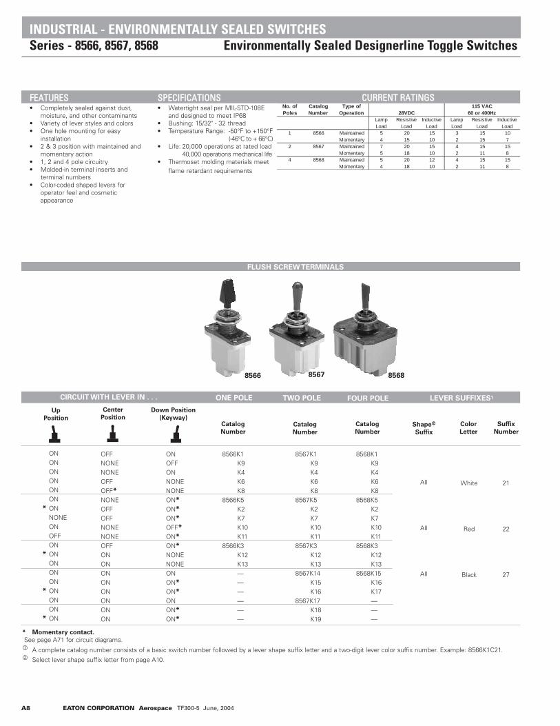
No. of Poles
Catalog Number
Type of Operation
1 8566 Maintained 5 20 15 3 15 10Momentary 4 15 10 2 15 7
2 8567 Maintained 7 20 15 4 15 15 Momentary 5 18 10 2 11 84 8568 Maintained 5 20 12 4 15 15 Momentary 4 18 10 2 11 8
Lamp Load
28VDC115 VAC
60 or 400HzInductive
LoadResistive
LoadInductive
LoadLamp Load
Resistive Load
FLUSH SCREW TERMINALS
8566 8567 8568
CIRCUIT WITH LEVER IN . . . ONE POLE TWO POLE FOUR POLE LEVER SUFFIXES1
Up
Position
Center
Position
Down Position
(Keyway)
ONONONONONON
* ONNONEONOFFON
* ONONONON
* ONONON
* ON
OFFNONENONEOFFOFF*
NONEOFFOFFNONENONEOFFONONONONONONONON
ONOFFONNONENONEON*
ON*
ON*
OFF*
ON*
ON*
NONENONEONON*
ON*
ONON*
ON*
8566K1K9K4K6K8
8566K5K2K7K10K11
8566K3K12K13——————
8567K1K9K4K6K8
8567K5K2K7K10K11
8567K3K12K13
8567K14K15K16
8567K17K18K19
8568K1K9K4K6K8
8568K5K2K7K10K11
8568K3K12K13
8568K15K16K17———
All
All
All
White
Red
Black
21
22
27
Catalog
Number
Catalog
Number
Catalog
NumberShape2
Suffix
Color
Letter
Suffix
Number
* Momentary contact.
See page A71 for circuit diagrams.1 A complete catalog number consists of a basic switch number followed by a lever shape suffix letter and a two-digit lever color suffix number. Example: 8566K1C21.2 Select lever shape suffix letter from page A10.
FFEEAATTUURREESS• Completely sealed against dust,
moisture, and other contaminants• Variety of lever styles and colors• One hole mounting for easy
installation• 2 & 3 position with maintained and
momentary action• 1, 2 and 4 pole circuitry• Molded-in terminal inserts and
terminal numbers• Color-coded shaped levers for
operator feel and cosmetic appearance
SSPPEECCIIFFIICCAATTIIOONNSS• Watertight seal per MIL-STD-108E
and designed to meet IP68• Bushing: 15/32" - 32 thread• Temperature Range: -50°F to +150°F
(-46°C to + 66°C)• Life: 20,000 operations at rated load
40,000 operations mechanical life• Thermoset molding materials meet
flame retardant requirements
CCUURRRREENNTT RRAATTIINNGGSS
INDUSTRIAL - ENVIRONMENTALLY SEALED SWITCHESSeries - 8566, 8567, 8568 Environmentally Sealed Designerline Toggle Switches

EATON CORPORATION Aerospace TF300-5 June, 2004 A9
Terminal Identification
STANDARD0.00 = inches
[0,0] = mm
Mounting dimensions for reference only. Non-functional terminals not supplied.
KEYWAY
.076
[1,9
3]
.432 [10,97]
33˚
16,5̊
.25[6,35]
"A"
FOR PLASTIC LEVER CAPSTYLES SEE CATALOG PAGE ##
.468
[11,
89]
.594
[15,
09]
.38[9,7]
.38[9,7]
1.25[31,7]
1 2 3
15/32-32 UN-2A THREADTO WITHIN
.060 [1,52] OF SHOULDER
#6-32 UNC-2A TERMINAL SCREWWITH INTERNAL TOOTH LOCKWASHER (SEMS)
DESCRIPTIONLEVER STYLE "A" .938
C .859D .893E .893F 1.021G .953J .950K .950 L .950
23,8321,8222,6822,6825,9324,2124,1324,1324,13
DIM. "A"INCHES
DIM. "A"METRIC
1.19
[30,
23]
M 1.150 29.21
KEYWAY
.076
[7
,93]
.432[10,97]
16.5
"A.4
68[1
1,89
]
.25
[6,3]
1.35
[34,
3]
#6-32 TERMINAL SCREW WITH INTERNAL TOOTHLOCKWASHER (SEMS)
.38
[9,7
]
.89
[22,
6]
.38[9,7]
.38[9,7]
1.32[33,5]
15/32-32 UN-2ATHREAD TO WITHIN
.060 [1,52] OF SHOULDER
MAX
MAX
MAX
FOR PLASTIC LEVER CAPSTYLES SEE CATALOG PAGE ##
1 2 3
4 5 6
DESCRIPTIONLEVER STYLE "A" .938
C .859D .893E .893F 1.021G .953J .950K .950
23,8321,8222,6822,6825,9324,2124,1324,1324,13
DIM. "A"INCHES
DIM. "A"METRIC
33˚16.5˚
L .950M 1.150 29,21
INDUSTRIAL - ENVIRONMENTALLY SEALED SWITCHESSeries - 8566, 8567, 8568 Environmentally Sealed Designerline Toggle Switches
MMOOUUNNTTIINNGG DDIIMMEENNSSIIOONNSS -- OONNEE PPOOLLEE // 88556666
MMOOUUNNTTIINNGG DDIIMMEENNSSIIOONNSS -- TTWWOO PPOOLLEE // 88556677
Terminal Identification
DESCRIPTION
LEVER STYLE “A”CDEFGJKLM
DIM. “A”
INCHES
DIM. “A”
METRIC
.938
.859
.893
.8931.021.953.950.950.9501.150
23,8321,8222,6822,6825,9324,2124,1324,1324,1329,21
DESCRIPTION
LEVER STYLE “A”CDEFGJKLM
DIM. “A”
INCHES
DIM. “A”
METRIC
.938
.859
.893
.8931.021.953.950.950.9501.150
23,8321,8222,6822,6825,9324,2124,1324,1324,1329,21

A10 EATON CORPORATION Aerospace TF300-5 June, 2004
DESCRIPTIONLEVER STYLE "A" .938
C .859D .893E .893F 1.021G .953J .950K .950 L .950M 1.150
23,8321,8222,6822,6825,9324,2124,1324,1324,13
DIM. "A"INCHES
DIM. "A"METRIC
FOR PLASTIC LEVER CAPSTYLES SEE CATALOG PAGE ##
.432 [10,97]
.076
[1,9
3]
KEYWAY
33˚
16.5̊
"A.4
68[1
1,89
]
.250
[6,35
]
1.35
[34,
3]
#6-32 TERMINALSCREW WITH INTERNALTOOTH LOCKWASHER (SEMS)
15/32-32 UN-2ATHREAD TO WITHIN
.060 [1,52] OF SHOULDER
.37
[9,4
].3
7[9
,4]
.37
[9,4
]
.38[9,6]
1.32[33,5]
.38[9,6]
1.64
[41,
6]
1 2
3
4
5
6
7
8
9
10
11
1229,21
Terminal Identification
Non-functional terminals not supplied.
STANDARD0.00 = inches
[0,0] = mm
Mounting dimensions for reference only.
LOCKING RING
0.480[12,19]
DIA. HOLE
0.37
5[9
,52]
0.130[3,30]
STYLE A
.40 DIA.[10,16]
.194 DIA.[4,92]
.360[9,14] .070
[1,78]
.194[4,93]
.250 DIA.[6,35]
.032[0,81]
STYLE C STYLE D
.208 DIA.[5,28]
.310 DIA.[7,87]
.094
[2,3
9]
MMOOUUNNTTIINNGG DDIIMMEENNSSIIOONNSS -- FFOOUURR PPOOLLEE // 88556688
OOPPTTIIOONNSS//AACCCCEESSSSOORRIIEESS
• Special mounting hardware• Mounting hardware furnished assembled• Terminal screws furnished assembled• Spade terminal adapters available• Panel seal, Part Number 32-341• Special circuits
• Standard colors available - White, red and black
PPAANNEELL CCUUTTOOUUTT DDIIMMEENNSSIIOONNSS
15/32 DIA. BUSHING
INDUSTRIAL - ENVIRONMENTALLY SEALED SWITCHESSeries - 8566, 8567, 8568 Environmentally Sealed Designerline Toggle Switches
0.44
5[1
1,30
]
0.062[1,57]
KEYWAY
0.480[12,19] DIA. HOLE
.325
[8,26]
.275
[6,99]
.090
[2,29]
.298
[7,57].194
[4,93].040
[1,02]
.390 [9,91]
STYLE GSTYLE FSTYLE E
.210 DIA.[5,33]
.345 DIA.[8,76]
300
.300 SQ
[7,62]
[4,93].194 DIA.
375
STYLE J
.250 []
STYLE LSTYLE K
.375[9,53]
.375 DIA.[9,53] .188 DIA.
[4,78]
.188[4,78]
.250[6,35]
.300
.146
.375[9,53] [7,62]
[3,71]
STYLE M
DESCRIPTION
LEVER STYLE “A”CDEFGJKLM
DIM. “A”
INCHES
DIM. “A”
METRIC
.938
.859
.893
.8931.021.953.950.950.9501.150
23,8321,8222,6822,6825,9324,2124,1324,1324,1329,21

EATON CORPORATION Aerospace TF300-5 June, 2004 A11
No. of
Poles
Catalog
Number
Type of
Operation
1 8530 Maintained 5 20 15 3 15 10Momentary 4 15 10 2 11 7
2 8531 Maintained 7 20 15 4 15 15 Momentary 5 18 10 2 11 84 8532 Maintained 5 20 12 4 15 15 Momentary 4 18 10 2 11 8
For the UL/CSA ratings, see page A70.
28VDC
115VAC
60 or 400Hz
Resistive Load
Inductive Load
Lamp Load
Resistive Load
Inductive Load
Lamp Load
SSTTAANNDDAARRDD LLEEVVEERR SSEELLEECCTTIIOONN TTAABBLLEECIRCUIT WITH LEVER IN . . . CATALOG NUMBER
ONE POLE
TWO POLE
Up
Position
Center
Position
Down Position
(Keyway)
ONONONONONONON*NONEONOFFONON*ON
OFFNONENONEOFFOFF*NONEOFFOFFNONENONEOFFONON
ONOFFONNONENONEON*ON*ON*OFF*ON*ON*NONENONE
8530K1K9K4K6K8
8530K5K2K7K10K11
8530K3K12K13
8530K91K99K94K96K98
8530K95K92K97K910K911
8530K93K912K913
8530K31K39K34K36K38
8530K35K32K37K310K311
8530K33K312K313
ONONONONONONON*NONEONOFFONON*ONONONON*ONONON*
OFFNONENONEOFFOFF*NONEOFFOFFNONENONEOFFONONONONONONONON
ON OFFONNONENONEON*ON*ON*OFF*ON*ON*NONENONEON ON*ON*ON ON*ON*
8531K1K9K4K6K8
8531K5K2K7K10K11
8531K3K12K13K14K15
8531K16K17K18K19
8531K91K99K94K96K98
8531K95K92K97K910K911
8531K93K912K913K914K915
8531K916K917K918K919
8531K31K39K34K36K38
8531K35K32K37K310K311
8531K33K312K313K314K315
8531K316K317K318K319
FOUR POLE
ONONONONONON
* ONNONEONOFFON
* ONONONON
* ON
OFFNONENONEOFFOFF*NONEOFFOFFNONENONEOFFONONONONON
ONOFFONNONENONEON*ON*ON*OFF*ON*ON*NONENONEON ON*ON*
8532K1K9K4K6K8
8532K5K2K7K10K11
8532K3K12K13K15K16K17
8532K91K99K94K96K98
8532K95K92K97K910K911
8532K93K912K913K915K916K917
8532K31K39K34K36K38
8532K35K32K37K310K311
8532K33K312K313K315K316K317
Screw
TerminalsSolder Lug
Terminals
Spade
Terminals
8530
8531
8532
* Momentary contact.See page A71 for circuit diagrams.
INDUSTRIAL - ENVIRONMENTALLY SEALED SWITCHESSeries - 8530, 8531, 8532 Econoswitch Sealed Toggle Switches
CCUURRRREENNTT RRAATTIINNGGSSFFEEAATTUURREESS• Environmentally sealed• 1, 2 and 4 pole Circuitry• One hole mounting for easy
installation• Multi-circuits• 2 & 3 position with maintained
and momentary action• Three types of termination
offered as standard
SSPPEECCIIFFIICCAATTIIOONNSS• Watertight seal per MIL-STD-108E
and designed to meet IP68• UL recognized and CSA certified• Three standard types of terminals:
Screw 6-32 UNC-2ASolder lug .125 [3,17] dia. holeSpade .250 [6,35] x .032
[0,81] thick• Life: 50,000 operations at rated load.
100,000 operations mechanical life.• Temperature Range: -50°F to +150°F
(-46°C to + 66°C)

A12 EATON CORPORATION Aerospace TF300-5 June, 2004
Terminal Identification
Terminal IdentificationSTANDARD0.00 = inches
[0,0] = mm
Mounting dimensions for reference only. Non-functional terminals not supplied.
KEYWAY
.076
[1
,93]
1.30
[33,
0]
1.28
[3
2,5]
1.51
[12,
9]
21 321 3
.594
[15,
09]
21 3
#6-32 UNC-2A TERMINAL SCREW, SEMS .125[3,17] .250 X .032 THK
[6,35] X [0,81]
1.25 [31,75]
SCREW TERMINAL SOLDER LUG SPADE TERMINAL
MAX
MAX
MAX
DIA. HOLE
33
16.5 .240 [6,10]
DIA.
15/32-32 UN-2ATHREAD TO WITHIN
.060 [1,52] OF SHOULDER
.690
[17,
53]
.470
[11,
94]
.432 [10.97]
ECONOSWITCH - ENVIRONMENTALLY SEALED SWITCHESSeries - 8530, 8531, 8532 Econoswitch Sealed Toggle Switches
MMOOUUNNTTIINNGG DDIIMMEENNSSIIOONNSS -- OONNEE PPOOLLEE // 88553300
MMOOUUNNTTIINNGG DDIIMMEENNSSIIOONNSS -- TTWWOO PPOOLLEE // 88553311

EATON CORPORATION Aerospace TF300-5 June, 2004 A13
Non-functional terminals not supplied.
Terminal Identification
STANDARD0.00 = inches
[0,0] = mm
Mounting dimensions for reference only.
LOCKING RING
0.480[12,19]
DIA. HOLE
0.37
5[9
,52]
0.130[3,30]
0.44
5[1
1,30
]
0.062[1,57]
KEYWAY
0.480[12,19] DIA. HOLE
ECONOSWITCH - ENVIRONMENTALLY SEALED SWITCHESSeries - 8530, 8531, 8532 Econoswitch Sealed Toggle Switches
OOPPTTIIOONNSS//AACCCCEESSSSOORRIIEESS
• Special mounting hardware• Mounting hardware furnished assembled• Terminal screws furnished assembled• Special circuits• Panel seal, Part Number 32-341• Custom wire harnesses• Mating connector available for two poles with spade
terminal• External jumpers available
- bussing jumper- reversing jumpers
PPAANNEELL CCUUTTOOUUTT DDIIMMEENNSSIIOONNSS15/32 DIA. BUSHING
DIA HOLE
15/32-32 UNS-2ATHREAD TO WITHIN
.060 [1,52] OF SHOULDER
8
9
6
321
1211
1.32 [33,5]
10
5
4
7
8
9
6
321
121110
5
4
7
8
9
6
321
121110
1.34
[3
4,0]
MAX
MAX
MAX
.468
[1
1,89
].6
9[1
7,5]
16.5˚
.240[6,10]
DIA.
KEYWAY
.076
[1,9
3]
.432[10,97]
1.32
[3
3,5]
.250 X .032 THK[6,35] X [0,81]
1.55
[3
9,3]
6-32 UNC-2A TERMINAL SCREW, SEMS .125[3,17]
5
4
7
1.64
[4
1,66
]
SOLDER LUGSCREW TERMINAL SPADE TERMINAL
33˚
MMOOUUNNTTIINNGG DDIIMMEENNSSIIOONNSS -- FFOOUURR PPOOLLEE// 88553322
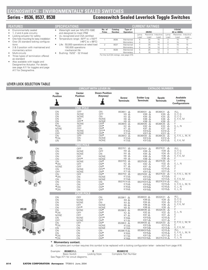
No. of
Poles
Catalog
Number
Type of
Operation
1 8536 Maintained 5 20 15 3 15 10Momentary 4 15 10 2 15 7
2 8537 Maintained 7 20 15 4 15 15 Momentary 5 18 10 2 11 84 8538 Maintained 5 20 12 4 15 15 Momentary 4 18 10 2 11 8
For the UL/CSA ratings, see page A70.
28VDC
115VAC
60 or 400Hz
Lamp Load
Resistive Load
Inductive Load
Lamp Load
Resistive Load
Inductive Load
A14 EATON CORPORATION Aerospace TF300-5 June, 2004
LLEEVVEERR LLOOCCKK SSEELLEECCTTIIOONN TTAABBLLEE
8536
8537
8538
CIRCUIT WITH LEVER IN . . . CATALOG NUMBER
ONE POLE
TWO POLE
Up
Position
Center
Position
Down Position
(Keyway)
ONONONONONON*ONNONEONOFFON*ONON
OFFNONENONEOFFOFF*NONEOFFOFFNONENONEOFFONON
ONOFFONNONENONEON*ON*ON*OFF*ON*ON*NONENONE
8536K1 K9 K4 K6 K8
8536K5 K2 K7 K10K11
8536K3 K12K13
8536K91K99K94K96K98
8536K95K92K97K910K911
8536K93K912K913
8536K31K39K34K36K38
8536K35K32K37K310K311
8536K33K312K313
ALLD, F, GD, F, GE, F, K, MFFE, L, NEFFE, F, K, L, M, NEE, F, K, M
ONONONONONON*ONNONEONOFFON*ONONONON*ON*ON
OFFNONENONEOFFOFF*NONEOFFOFFNONENONEOFFONONONONONON
ON OFFONNONENONEON*ON*ON*OFF*ON*ON*NONENONEON ON*ON*ON*
8537K1K9K4K6K8
8537K5K2K7K10K11
8537K3K12K13
8537K14K15K16K19
8537K91K99K94K96K98
8537K95K92K97K910K911
8537K93K912K913
8537K914K915K916K919
8537K31K39K34K36K38
8537K35K32K37K310K311
8537K33K312K313
8537K314K315K316K319
ALLD, F, GD, F, GE, F, K, MFFE, L, NEFFE, F, K, L, M, NEE, F, K, MALLE, F, K, L, M, NE, L, NE, L, N
FOUR POLE
ONONONONONON*ONNONEONOFFON*ONONONON*ON*ON
OFFNONENONEOFFOFF*NONEOFFOFFNONENONEOFFONONONONONON
ONOFFONNONENONEON*ON*ON*OFF*ON*ON*NONENONEON ON*ON*ON*
8538K1K9K4K6K8
8538K5K2K7K10K11
8538K3K12K13
8538K15K16K17K19
8538K91K99K94K96K98
8538K95K92K97K910K911
8538K93K912K913
8538K915K916K917
8537K919
8532K31K39K34K36K38
8532K35K32K37K310K311
8532K33K312K313K315K316K317
8537K319
ALLD, F, GD, F, GE, F, K, MFFE, L, NEFFE, F, K, L, M, NEE, F, K, MALLE, F, K, L, M, NE, L, NE, L, N
Screw
Terminals
Solder Lug
TerminalsSpade
Terminals
Available
Locking
Configurations
* Momentary contact. Complete part number requires this symbol to be replaced with a locking configuration letter - selected from page A16.
Example: 8536K31 E 8536K31E
Basic Switch Locking Style Complete Part NumberSee Page A71 for circuit diagrams.
ECONOSWITCH - ENVIRONMENTALLY SEALED SWITCHESSeries - 8536, 8537, 8538 Econoswitch Sealed Leverlock Toggle Switches
FFEEAATTUURREESS• Environmentally sealed• 1, 2 and 4 pole circuitry• Locking actuator for safety• One hole mounting for easy installation• Over 25 standard locking configura-
tions • 2 & 3 position with maintained and
momentary action• Multi-circuits• Three types of termination offered
as standard• Also available with toggle and
Designerline Actuator. For details see page A11 for toggles and page A17 for Designerline.
SSPPEECCIIFFIICCAATTIIOONNSS• Watertight seal per MIL-STD-108E
and designed to meet IP68• UL recognized and CSA certified• Temperature range: -50°F to +150°F
(-46°C to + 66°C)• Life: 50,000 operations at rated load
100,000 operations mechanical life
• Bushing: 15/32" - 32 thread
CCUURRRREENNTT RRAATTIINNGGSS

EATON CORPORATION Aerospace TF300-5 June, 2004 A15
Terminal IdentificationSTANDARD0.00 = inches
[0,0] = mm
Mounting dimensions for reference only. Non-functional terminals not supplied.
KEYWAY
.076
[1
,93]
.432 [10,97]
1.05 [26,67]1.14 [28,96]
.47
[11,
94]
1.30
[33,
0]
1.28
[3
2,5]
1.51
[12,
9]
21 321 3
.594
[15,
09]
21 3
.42 DIA.[10,67]
#6-32 UNC-2A TERMINAL SCREW, SEMS .125[3,17] .250 X .032 THK
[6,35] X [0,81]
33
16.5
LOCKEDAPPROX.UNLOCKED
1.25 [31,75]
SCREW TERMINAL SOLDER LUG SPADE TERMINAL
MAX
MAX
MAX
DIA. HOLE
15/32-32 UNS-2ATHREAD TO WITHIN.060 [1,52] OF SHOULDER
DIA HOLE
1.34
[3
4,0]
KEYWAY
.076
[1,9
3]
.432[10,97]
1.32
[3
3,5]
.250 X .032 THK[6,35] X [0,81]
1.55
[1
4,1]
6-32 UNC-2A TERMINAL SCREW,SEMS.125
[3,17]
MAX
MAX M
AX
54 6
21 3
54 6
21 3
54 6
.89
[22,
6]
21 3
1.32 [33,5]
SCREW TERMINAL SOLDER LUG SPADE TERMINAL
1.05 [26,67]1.14 [28,96]
.47
[11,
94]
.42 DIA.[10,67]
33
16.5
LOCKEDAPPROX.UNLOCKED
15/32-32 UNS-2ATHREAD TO WITHIN.060 [1,52] OF SHOULDER
ECONOSWITCH - ENVIRONMENTALLY SEALED SWITCHESSeries - 8536, 8537, 8538 Econoswitch Sealed Leverlock Toggle Switches
MMOOUUNNTTIINNGG DDIIMMEENNSSIIOONNSS -- OONNEE PPOOLLEE // 88553366
Terminal Identification
MMOOUUNNTTIINNGG DDIIMMEENNSSIIOONNSS -- TTWWOO PPOOLLEE // 88553377

A16 EATON CORPORATION Aerospace TF300-5 June, 2004
Non-functional terminals not supplied.
DIA HOLE
1.34
[3
4,0]
1.32
[3
3,5]
.250 X .032 THK[6,35] X [0,81]
1.55
[3
9,9]
6-32 UNC-2A TERMINAL SCREW, SEMS .125[3,17]
MAX
MAX M
AX
8
9
6
321
1211
1.32 [33,5]
10
5
4
7
8
9
6
321
121110
5
4
7
8
9
6
321
121110
KEYWAY
.076
[1,9
3]
.432[10,97]
5
4
7
1.64
[4
1,66
]
SOLDER LUGSCREW TERMINAL SPADE TERMINAL
1.05 [26,67]1.14 [28,96]
.47
[11,
94]
.42 DIA.[10,67]
33
16.5
LOCKEDAPPROX.UNLOCKED
15/32-32 UNS-2ATHREAD TO WITHIN.060 [1,52] OF SHOULDER
STANDARD0.00 = inches
[0,0] = mm
Mounting dimensions for reference only.
LOCKING RING
0.480[12,19]
DIA. HOLE
0.37
5[9
,52]
0.130[3,30]
LOCKED OUT OFCENTER AND SIDEOPPOSITE KEYWAY
LOCKED INCENTER AND
SIDE OPPOSITEKEYWAY
LOCKEDOUT OFKEYWAY
SIDE
LOCKED OUTOF AND INTO
SIDE OPPOSITEKEYWAY
LOCKED OUTOF SIDE
OPPOSITEKEYWAY
LOCKED OUTOF AND INTOKEYWAY SIDE
LOCKED IN 3POSITIONS
LOCKED INCENTER AND
IN KEYWAY SIDE
LOCKED OUTOF CENTERPOSITION
LOCKED INCENTER
POSITION
LOCKEDIN SIDE
OPOSITEKEYWAY
LOCKED INKEYWAY
SIDE
LOCKED OUTOF CENTER
AND KEYWAYSIDE
A B D E F G H
J K L M N P
ECONOSWITCH - ENVIRONMENTALLY SEALED SWITCHESSeries - 8536, 8537, 8538 Econoswitch Sealed Leverlock Toggle Switches
Terminal Identification
OOPPTTIIOONNSS//AACCCCEESSSSOORRIIEESS
• Special mounting hardware• Mounting hardware furnished assembled• Terminal screws furnished assembled• Special circuits• Panel seals, Part Number 32-341
PPAANNEELL CCUUTTOOUUTT DDIIMMEENNSSIIOONNSS
15/32 DIA. BUSHING
0.44
5[1
1,30
]
0.062[1,57]
KEYWAY
0.480[12,19] DIA. HOLE
MMOOUUNNTTIINNGG DDIIMMEENNSSIIOONNSS -- FFOOUURR PPOOLLEE // 88553388
Figures A thru P do not represent details of construction.They schematically illustrate locking function.

EATON CORPORATION Aerospace TF300-5 June, 2004 A17
SSEELLEECCTTIIOONN TTAABBLLEE
8533
8534
8535
CIRCUIT WITH LEVER IN . . . CATALOG NUMBER
ONE POLE
TWO POLE
Up
Position
Center
Position
Down Position
(Keyway)
ONONONONONONONNONEONOFFONONON
OFFNONENONEOFFOFFNONEOFFOFFNONENONEOFFONON
ONOFFONNONENONEON*ON*ON*OFF*ON*ON*NONENONE
8533K1K9K4K6K8
8533K5K2K7K10K11
8533K3K12K13
8533K91K99K94K96K98
8533K95K92K97K910K911
8533K93K912K913
88533K31K39K34K36K38
8533K35K32K37K310K311
8533K33K312K313
All
All
All
White
Red
Black
21
22
27
ONONONONONONONNONEONOFFON
* ONONONON
* ON
OFFNONENONEOFFOFFNONEOFFOFFNONENONEOFFONONONONON
ON OFFONNONENONEON*ON*ON*OFF*ON*ON*NONENONEON ON*ON*
8534K1K9K4K6K8
8534K5K2K7K10K11
8534K3K12K13
8534K14K15K16
8534K91K99K94K96K98
8534K95K92K97K910K911
8534K93K912K913
8534K914K915K916
8534K31K39K34K36K38
8534K35K32K37K310K311
8534K33K312K313
8534K314K315K316
All
All
All
White
Red
Black
21
22
27
FOUR POLE
ONONONONONON
* ONNONEONOFFON
* ONONONON
* ON
OFFNONENONEOFFOFF*NONEOFFOFFNONENONEOFFONONONONON
ONOFFONNONENONEON*ON*ON*OFF*ON*ON*NONENONEON ON*ON*
8535K1K9K4K6K8
8535K5K2K7K10K11
8535K3K12K13
8535K15K16K17
8535K91K99K94K96K98
8535K95K92K97K910K911
8535K93K912K913
8535K915K916K917
8535K31K39K34K36K38
8535K35K32K37K310K311
8535K33K312K313
8535K315K316K317
All
All
All
White
Red
Black
21
22
27
Screw
Terminals 1Solder Lug
Terminals 1Spade
Terminals 1
Shape
Suffix 2
Color
Letter
Suffix
Number
* Momentary contact.
1A complete catalog number consists of a basic switch number followed by a lever shape suffix letter and a two-digit lever color suffix number. Example: 8533K91E27.See page A71 for circuit diagrams.
2Select lever shape suffix letter from page A19.
No. of
Poles
Catalog
Number
Type of
Operation
1 8533 Maintained 5 20 15 3 15 10Momentary 4 15 10 2 11 7
2 8534 Maintained 7 20 15 4 15 15 Momentary 5 18 10 2 11 84 8535 Maintained 5 20 12 4 15 15 Momentary 4 18 10 2 11 8
For the UL/ CSA ratings, see page A70.
28VDC
115 VAC
60 or 400Hz
Lamp Load
Resistive Load
Inductive Load
Lamp Load
Resistive Load
Inductive Load
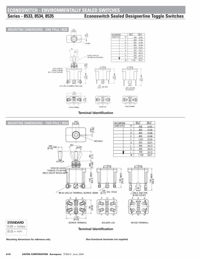
ECONOSWITCH - ENVIRONMENTALLY SEALED SWITCHESSeries - 8533, 8534, 8535 Econoswitch Sealed Designerline Toggle Switches
CCUURRRREENNTT RRAATTIINNGGSSFFEEAATTUURREESS
• Environmentally sealed• 1, 2 and 4 pole circuitry• One hole mounting for easy installation• Variety of lever styles and colors• Color-coded, shaped levers for
operator feel and cosmetic appearance• 2 & 3 position with maintained and
momentary action• Three types of termination offered
as standard• Multi-circuits• Also available with toggle and lever
lock Actuator. For details, see page A11 for toggles and page A14 for lever locks.
SSPPEECCIIFFIICCAATTIIOONNSS
• Watertight seal per MIL-STD-108E designed to meet IP68
• UL recognized and CSA certified• Bushing: 15/32" - 32 thread• Temperature range: -50°F to +150°F
(-46°C to + 66°C)• Life: 50,000 operations at rated load
100,000 operations mechanical life
A18 EATON CORPORATION Aerospace TF300-5 June, 2004
Terminal Identification
STANDARD0.00 = inches
[0,0] = mm
Mounting dimensions for reference only. Non-functional terminals not supplied.
KEYWAY
PLASTIC LEVER CAPSEE PAGE xxxx FOR DETAILS
.076
[1
,93]
.432 [10,97]
.468
[11,
89]
1.30
[33,
0]
1.28
[3
2,5]
1.51
[36,
3]
21 321 3
.594
[15,
09]
21 3
15/32-32 UNS-2ATHREAD TO WITHIN
.060 [1,52] OF SHOULDER
#6-32 UNC-2A TERMINAL SCREW, SEMS .125[3,17] .250 X .032 THK
[6,35] X [0.81]
33
16.5
1.25 [31,7]
SCREW TERMINAL SOLDER LUG SPADE TERMINAL
MAX
MAX
MAX
DIA. HOLE
DESCRIPTIONLEVER STYLE "A" .938
C .859D .893E .893F 1.021G .953J .950K .950 L
23,8321,8222,6822,6825,9324,2124,1324,1324,13
DIM. "A"INCHES
DIM. "A"METRIC
M 29,21 .950
1.150
DESCRIPTIONLEVER STYLE "A" .938
C .859D .893E .893F 1.021G .953J .950K .950 L
23,8321,8222,6822,6825,9324,2124,1324,1324,13
DIM. "A"INCHES
DIM. "A"METRIC
M 29,21 .950
1.150
MMOOUUNNTTIINNGG DDIIMMEENNSSIIOONNSS -- OONNEE PPOOLLEE // 88553333
Terminal Identification
MMOOUUNNTTIINNGG DDIIMMEENNSSIIOONNSS -- TTWWOO PPOOLLEE // 88553344
ECONOSWITCH - ENVIRONMENTALLY SEALED SWITCHESSeries - 8533, 8534, 8535 Econoswitch Sealed Designerline Toggle Switches
DESCRIPTIONLEVER STYLE "A" .938
C .859D .893E .893F 1.021G .953J .950K .950 L
23,8321,8222,6822,6825,9324,2124,1324,1324,13
DIM. "A"INCHES
DIM. "A"METRIC
M 29,21 .950
1.150
DESCRIPTIONLEVER STYLE "A" .938
C .859D .893E .893F 1.021G .953J .950K .950 L
23,8321,8222,6822,6825,9324,2124,1324,1324,13
DIM. "A"INCHES
DIM. "A"METRIC
M 29,21 .950
1.150

EATON CORPORATION Aerospace TF300-5 June, 2004 A19
Terminal Identification
DIA HOLE
15/32-32 UNS-2ATHREAD TO WITHIN
.060 [1,52] OF SHOULDER
8
9
6
321
1211
1.32 [33,5]
10
5
4
7
8
9
6
321
121110
5
4
7
8
9
6
321
1211101.
34
[34,
0]M
AX
MAX
MAX
.468
[1
2,34
]
16.5˚
KEYWAY
.076
[1,9
3]
.432[10,97]
1.32
[3
3,5]
.250 X .032 THK[6,35] X [0,81]
1.55
[3
9,3]
6-32 UNC-2A TERMINAL SCREW, SEMS .125[3,17]
5
4
7
1.64
[4
1,66
]
SOLDER LUGSCREW TERMINAL SPADE TERMINAL
PLASTIC LEVER CAPSEE PAGE A-9 FOR DETAILS
33˚
DESCRIPTIONLEVER STYLE "A" .938
C .859D .893E .893F 1.021G .953J .950K .950 L
23,8321,8222,6822,6825,9324,2124,1324,1324,13
DIM. "A"INCHES
DIM. "A"METRIC
M 29,21 .950
1.150
STANDARD0.00 = inches
[0,0] = mm
Mounting dimensions for reference only.
STYLE A
.40 DIA.[10,16]
.194 DIA.[4,92]
.360[9,14] .070
[1,78]
.194[4,93]
.250 DIA.[6,35]
.032[0,81]
STYLE C STYLE D
.208 DIA.[5,28]
.310 DIA.[7,87]
.094
[2,3
9]
ECONOSWITCH - ENVIRONMENTALLY SEALED SWITCHESSeries - 8533, 8534, 8535 Econoswitch Sealed Designerline Toggle Switches
MMOOUUNNTTIINNGG DDIIMMEENNSSIIOONNSS -- FFOOUURR PPOOLLEE // 88553355
Non-functional terminals not supplied.
OOPPTTIIOONNSS//AACCCCEESSSSOORRIIEESS
• Special mounting hardware• Mounting hardware furnished assembled• Special circuits• Panel seal, Part Number 32-341
• Standard colors available - White, red and black
PPAANNEELL CCUUTTOOUUTT DDIIMMEENNSSIIOONNSS
LOCKING RING
0.480[12,19]
DIA. HOLE
0.37
5[9
,52]
0.130[3,30]
15/32 DIA. BUSHING
0.44
5[1
1,30
]
0.062[1,57]
KEYWAY
0.480[12,19] DIA. HOLE
.325
[8,26]
.275
[6,99]
.090
[2,29]
.298
[7,57].194
[4,93].040
[1,02]
.390 [9,91]
STYLE GSTYLE FSTYLE E
.210 DIA.[5,33]
.345 DIA.[8,76]
300
.300 SQ
[7,62]
[4,93].194 DIA.
STYLE J
.250 []
STYLE LSTYLE K
.375[9,53]
.375 DIA.[9,53] .188 DIA.
[4,78]
.188[4,78]
.250[6,35]
.300
.146
.375[9,53] [7,62]
[3,71]
STYLE M

No. of Poles
Catalog Number
Type of Operation
1 8500 Maintained 5 20 15 3 15 10Momentary 4 15 10 2 15 7
2 8501 Maintained 7 20 15 4 15 15 Momentary 5 18 10 2 11 84 8502 Maintained 5 20 12 4 15 15 Momentary 4 18 10 2 11 8
Minimum Rating: "Intermediate Current" per MIL-S-3950.
28VDC115 VAC
60 or 400HzLamp Load
Resistive Load
Inductive Load
Lamp Load
Resistive Load
Inductive Load
A20 EATON CORPORATION Aerospace TF300-5 June, 2004
SSTTAANNDDAARRDD LLEEVVEERR SSEELLEECCTTIIOONN TTAABBLLEE
8500 8501 8502
Up
Position
Center
Position
Down Position
(Keyway)
ONONONONONON
* ONNONEONOFFON
* ONONONON
* ONONON
* ON
OFFNONENONEOFFOFF*
NONEOFFOFFNONENONEOFFONONONONONONONON
ONOFFONNONENONEON*
ON*
ON*
OFF*
ON*
ON*
NONENONEONON*
ON*
ONON*
ON*
8500K1K9K4K6K8
8500K5K2K7K10K11
8500K3K12K13——————
MS24523-21-22-23-24-25
MS24523-26-27-28-29-30
MS24523-31-32-33——————
MS24524-21-22-23-24-25
MS24524-26-27-28-29-30
MS24524-31-32-33
MS27407-1-2-3-4-5-6
8501K1K9K4K6K8
8501K5K2K7K10K11
8501K3K12K13
8501K14K15K16K17K18K19
MS24525-21-22-23-24-25
MS24525-26-27-28-29-30
MS24525-31-32-33
MS27406-1-2-3———
8502K1K9K4K6K8
8502K5K2K7K10K11
8502K3K12K13
8502K15K16K17———
Catalog
Number
MS Part
NumberMS Part
Number
Catalog
Number
Catalog
Number
MS Part
Number
* Momentary contact.
See page A71 for circuit diagrams.
MILITARY - ENVIRONMENTALLY SEALED SWITCHESSeries - 8500, 8501, 8502 MIL-S-3950 Toggle Switches
FFEEAATTUURREESS
• Environmentally sealed• 1, 2 and 4 pole circuitry• 2 & 3 position with maintained and
momentary action• Molded-in terminal inserts and
terminal numbers
SSPPEECCIIFFIICCAATTIIOONNSS
• Environmentally sealed per MIL-S-3950• MS approved and QPL'd per MIL-S-3950• Thermoset molding materials meet
flame retardant requirements• Bushing: 15/32" - 32 thread• Temperature Range: -85°F to +160°F
(-65°C to +71°C)• Life: 20,000 operations at rated load
40,000 operations mechanical life
CCUURRRREENNTT RRAATTIINNGGSS
CIRCUIT WITH LEVER IN . . . ONE POLE TWO POLE FOUR POLE
Minimum Rating: “Intermediate Current” per MIL-S-3950

EATON CORPORATION Aerospace TF300-5 June, 2004 A21
Terminal Identification
STANDARD0.00 = inches
[0,0] = mm
Mounting dimensions for reference only. Non-functional terminals not supplied.
KEYWAY
33
16.5
.240 [6,10]
DIA.
15/32-32 UN-2ATHREAD TO WITHIN
.060 [1,52] OF SHOULDER
#6-32 TERMINAL SCREW WITH INTERNAL TOOTH LOCKWASHER (SEMS)
1.270[32,26]
.380[9,65]
.380[9,65]
.432 [10,97]
.076
[1,9
3].6
90
[17,
53]
.470
[11,
94]
1.18
[29,
9].63
5[16
,13]
1 2 3
.250
[6,35
]
MAX
MAX
MAX
.432 [10,97]
.076
[1,9
3]
KEYWAY
.240 [6,10]
DIA. 33˚
16.5̊
.690
[17,
53]
.470
[11,
94]
1.10
0[2
7,94
]
.130
[3,3
0]
.250
[6,35
].1
30[3,
30]
#6-32 TERMINALSCREW WITH INTERNAL TOOTHLOCKWASHER (SEMS)
.380
[9,6
5]
14
25
36
.910
[23,
11]
.380[9,65]
.380[9,65]
1.340[34,04]
15/32-32 UN-2ATHREAD TO WITHIN
.060 [1,52] OF SHOULDER MAX
1.37
0[3
4,80
]M
AXM
AX
MAX
MILITARY - ENVIRONMENTALLY SEALED SWITCHESSeries - 8500, 8501, 8502 MIL-S-3950 Toggle Switches
MMOOUUNNTTIINNGG DDIIMMEENNSSIIOONNSS -- OONNEE PPOOLLEE // 88550000
Terminal Identification
MMOOUUNNTTIINNGG DDIIMMEENNSSIIOONNSS -- TTWWOO PPOOLLEE // 88550011

A22 EATON CORPORATION Aerospace TF300-5 June, 2004
Non-functional terminals not supplied.
Terminal Identification
90-4078.AI
.432 [10,97]
.076
[1,9
3]
KEYWAY
.240 [6.10]
DIA.33˚
16.5̊
.690
[17,
53]
.470
[11,
94]
1.10
0[2
7,94
]
.250
[6,35
] 1.37
0[3
4,80
]
#6-32 TERMINALSCREW WITH INTERNALTOOTH LOCKWASHER (SEMS)
.370
[9,4
0].3
70[9
,40]
.370
[9,4
0] 1.66
0[4
2,16
]
.380[9,65]
.380[9,65]
1.340[34,04]
15/32-32 UN-2ATHREAD TO WITHIN
.060 [1,52] OF SHOULDER MAX
.130
[3,3
0] MAX
MAX
MAX
.130
[3,3
0]
107
41
12
118
52
96
3
STANDARD0.00 = inches
[0,0] = mm
Mounting dimensions for reference only.
LOCKING RING
0.480[12,19]
DIA. HOLE
0.37
5[9
,52]
0.130[3,30]
0.44
5[1
1,30
]
0.062[1,57]
KEYWAY
0.480[12,19] DIA. HOLE
MILITARY - ENVIRONMENTALLY SEALED SWITCHESSeries - 8500, 8501, 8502 MIL-S-3950 Toggle Switches
MMOOUUNNTTIINNGG DDIIMMEENNSSIIOONNSS -- FFOOUURR PPOOLLEE // 88550022
OOPPTTIIOONNSS//AACCCCEESSSSOORRIIEESS
• Special mounting hardware• Mounting hardware furnished assembled• Terminal screws furnished assembled• Special circuits• Panel seal, part number 32-341 (See
Accessories and Custom Components section)
• Special "3 Cateye" luminous lever attachment
• Lever extensions and attachable tips (See Accessories and Custom Components section)
• Custom wiring harnesses
PPAANNEELL CCUUTTOOUUTT DDIIMMEENNSSIIOONNSS
15/32 DIA. BUSHING

EATON CORPORATION Aerospace TF300-5 June, 2004 A23
No. of Poles
Catalog Number
Type of Operation
1 8503 Maintained 5 20 15 3 15 10Momentary 4 15 10 2 15 7
2 8504 Maintained 7 20 15 4 15 15 Momentary 5 18 10 2 11 84 8505 Maintained 5 20 12 4 15 15 Momentary 4 18 10 2 11 8
Minimum Rating: "Intermediate Current" per MIL-S-3950.
28VDC115 VAC
60 or 400HzLamp Load
Resistive Load
Inductive Load
Lamp Load
Resistive Load
Inductive Load
LLEEVVEERR LLOOCCKK SSEELLEECCTTIIOONN TTAABBLLEE
8503 8504 8505
CIRCUIT WITH LEVER IN . . . ONE POLE TWO POLE FOUR POLE
Up
Position
Center
PositionLever 1
Lock
Bushing
Style
Down Position
(Keyway)
ONONONONONONONONONONONONONONONONONONONONONONON ONON
* ON* ON* ON
NONEONOFFONONONON
OFFOFFOFFOFFOFFOFFOFFOFFOFFOFFOFFOFFOFFNONENONENONENONENONENONEOFFOFFOFFOFFOFF *NONEOFFOFFOFFOFFNONENONEOFFOFFOFFOFF
ONONONONONONONONONONONONONOFFOFFOFFONONONNONENONENONENONENONEON *ON *ON *ON *ON *OFF*ON *ON *ON *ON *ON *
ABDEFGHJKL MNPDFGDFGEFKMFFELNEFFEFKL
8503K1K27K5K2K28
8503K3K29K30K31K32
8503K33K4K34K10K35
8503K9K6K36K7K16
8503K37K38K11K22K20
8503K12K39K14K15K21
8503K19K18K40K41K13
MS24658-21A-21B-21D-21E-21F
MS24658-21G-21H-21J-21K-21L
MS24658-21M-21N-21P-22D-22F
MS24658-22G-23D-23F-23G-24E
MS24658-24F-24K-24M-25F-26F
MS24658-27E-27L-27N-28E-29F
MS24658-30F-31E-31F-31K-31L
MS24659-21A-21B-21D-21E-21F
MS24659-21G-21H-21J-21K-21L
MS24659-21M-21N-21P-22D-22F
MS24659-22G-23D-23F-23G-24E
MS24659-24F-24K-24M-25F-26F
MS24659-27E-27L-27N-28E-29F
MS24659-30F-31E-31F-31K-31L
8504K1K27K5K2K28
8504K3K29K30K31K32
8504K33K4K34K10K35
8504K9K6K36K7K16
8504K37K38K11K22K20
8504K12K39K14K15K21
8504K19K18K40K41K13
MS24660-21A-21B-21D-21E-21F
MS24660-21G-21H-21J-21K-21L
MS24660-21M-21N-21P-22D-22F
MS24660-22G-23D-23F-23G-24E
MS24660-24F-24K-24M-25F-26F
MS24660-27E-27L-27N-28E-29F
MS24660-30F-31E-31F-31K-31L
8505K1K27K5K2K28
8505K3K29K30K31K32
8505K33K4K34K10K35
8505K9K6K36K7K16
8505K37K38K11K22K20
8505K12K39K14K15K21
8505K19K18K40K41K13
Catalog
NumberMS Part
Number
Flush Screw Terminals Flush Screw Terminals Flush Screw Terminals
MS Part
Number
Catalog
NumberCatalog
Number
MS Part
Number
* Momentary contact.Indicates direction against which lever is locked.See page A71 for circuit diagrams.
1 Reference bushing styles on page A26.
MILITARY - ENVIRONMENTALLY SEALED SWITCHESSeries - 8503, 8504, 8505 MIL-S-3950 Lever Lock Switches
FFEEAATTUURREESS
• Environmentally sealed• 1, 2 and 4 pole circuitry• 2 & 3 position with
maintained and momentary action• Locking actuator for safety• Molded-in terminal inserts and
terminal numbers
SSPPEECCIIFFIICCAATTIIOONNSS
• Environmentally sealed per MIL-S-3950• MS approved and QPL'd per MIL-S-3950• Thermoset molding materials meet
flame retardant requirements• Bushing: 15/32" - 32 thread• Temperature Range: -85°F to +160°F
(-65°C to +71°C)• Life: 20,000 operations at rated load
40,000 operations mechanical life
CCUURRRREENNTT RRAATTIINNGGSS
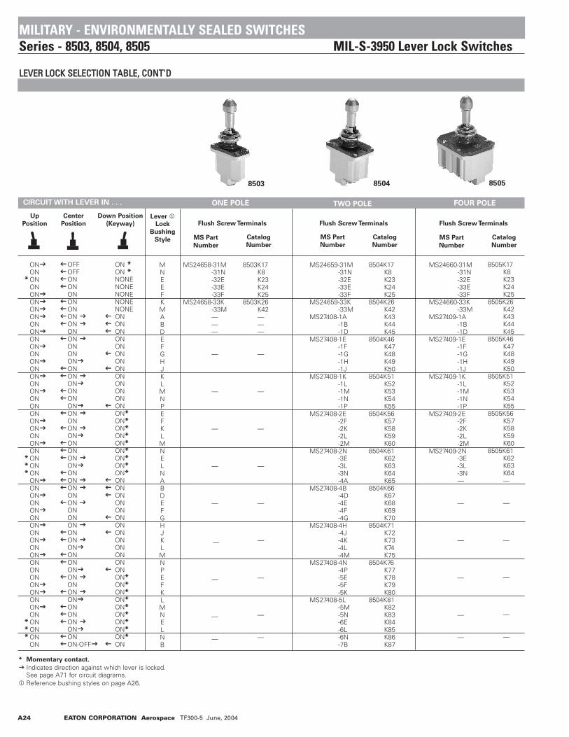
A24 EATON CORPORATION Aerospace TF300-5 June, 2004
LLEEVVEERR LLOOCCKK SSEELLEECCTTIIOONN TTAABBLLEE,, CCOONNTT''DD
8503 8504 8505
CIRCUIT WITH LEVER IN . . . ONE POLE TWO POLE FOUR POLE
Up
Position
Center
PositionLever 1
Lock
Bushing
Style
Down Position
(Keyway)
ONON
* ONONONONONONONONONONONONONONONONONONONONONONONON
* ON* ON* ON
ONONONONONONONONONONONONONONONONONONON
* ON* ON* ON
ON
OFFOFFONONONONONONONONONONONONONONONONONONONONONONONONONONONONONONONONONONONONONONONONONONONONONONONONONON-OFF
ON *ON *NONENONENONENONENONEON ONONONONONONONONONONONONON*ON*ON*ON*ON*ON*ON*ON*ON*ONONONONONONONONONONONONONON*ON*ON*ON*ON*ON*ON*ON*ON*ON
MNEEFKMABDEFGHJKL MNPEFKLMNELNABDEFGHJKLMNPEFKLMNELNB
8503K17K8K23K24K25
8503K26K42———
—
—
—
—
—
—
—
—
—
MS24658-31M-31N-32E-33E-33F
MS24658-33K-33M———
—
—
—
—
—
—
—
—
—
MS24659-31M-31N-32E-33E-33F
MS24659-33K-33M
MS27408-1A-1B-1D
MS27408-1E-1F-1G-1H-1J
MS27408-1K-1L-1M-1N-1P
MS27408-2E-2F-2K-2L-2M
MS27408-2N-3E-3L-3N-4A
MS27408-4B-4D-4E-4F-4G
MS27408-4H-4J-4K-4L-4M
MS27408-4N-4P-5E-5F-5K
MS27408-5L-5M-5N-6E-6L-6N-7B
8504K17K8K23K24K25
8504K26K42K43K44K45
8504K46K47K48K49K50
8504K51K52K53K54K55
8504K56K57K58K59K60
8504K61K62K63K64K65
8504K66K67K68K69K70
8504K71K72K73K74K75
8504K76K77K78K79K80
8504K81K82K83K84K85K86K87
MS24660-31M-31N-32E-33E-33F
MS24660-33K-33M
MS27409-1A-1B-1D
MS27409-1E-1F-1G-1H-1J
MS27409-1K-1L-1M-1N-1P
MS27409-2E-2F-2K-2L-2M
MS27409-2N-3E-3L-3N—
—
—
—
—
—
8505K17K8K23K24K25
8505K26K42K43K44K45
8505K46K47K48K49K50
8505K51K52K53K54K55
8505K56K57K58K59K60
8505K61K62K63K64—
—
—
—
—
—
Catalog
NumberMS Part
Number
Flush Screw Terminals Flush Screw Terminals Flush Screw Terminals
MS Part
Number
Catalog
Number
Catalog
Number
MS Part
Number
* Momentary contact.
Indicates direction against which lever is locked.See page A71 for circuit diagrams.
1 Reference bushing styles on page A26.
MILITARY - ENVIRONMENTALLY SEALED SWITCHESSeries - 8503, 8504, 8505 MIL-S-3950 Lever Lock Switches

EATON CORPORATION Aerospace TF300-5 June, 2004 A25
Mounting dimensions for reference only. Non-functional terminals not supplied.
KEYWAY
15/32-32 UN-2ATHREAD TO WITHIN
.060 [1,52] OF SHOULDER
#6-32 TERMINAL SCREW WITH INTERNAL TOOTH LOCKWASHER (SEMS)
1.270[32,26]
.380[9,65]
.380[9,65]
.432 [10,97]
.076
[1,9
3].4
70[1
1,94
]1.
18[2
9,9]
.635
[16,
13]
1 2 3
.250
[6,35
]
MAX
MAX
MAX
.420 [10,67]
DIA. 33˚16.5̊
1.05
[26,
6]LO
CKED
1.14
[28,
6]UN
LOCK
ED
MILITARY - ENVIRONMENTALLY SEALED SWITCHESSeries - 8503, 8504, 8505 MIL-S-3950 Lever Lock Switches
MMOOUUNNTTIINNGG DDIIMMEENNSSIIOONNSS -- OONNEE PPOOLLEE // 88550033
Terminal Identification
.432 [10,97]
.076
[1,9
3]
KEYWAY
.420 [10,67]
DIA. 33˚16.5̊
1.05
[26,
6]LO
CKED
1.14
[28,
6]UN
LOCK
ED
.470
[11,
94]
1.10
0[2
7,94
]
.25
0[6
,35]
.130
[3,3
0]
1.37
0[3
4,80
]
#6-32 TERMINAL SCREW WITH INTERNAL TOOTH LOCKWASHER (SEMS)
.380
[9,6
5]
.910
[23,
11]
.380[9,65]
.380[9,65]
1.340[34,04]
15/32-32 UN-2ATHREAD TO WITHIN.060 [1,52] OF SHOULDER
MAX
MAX
MAX
MAX
.130 [3,3]
1 2 3
4 5 6
MMOOUUNNTTIINNGG DDIIMMEENNSSIIOONNSS -- TTWWOO PPOOLLEE // 88550044
Terminal Identification
STANDARD0.00 = inches
[0,0] = mm

A26 EATON CORPORATION Aerospace TF300-5 June, 2004
Non-functional terminals not supplied.
Terminal Identification
107
4
1 35
69
82
11 12
.432 [10,97]
.076
[1,9
3]
KEYWAY
33˚16.5̊
1.10
0[2
7,94
]
.250
[6,3
5] 1.37
0[3
4,80
]
#6-32 TERMINALSCREW WITH INTERNALTOOTH LOCKWASHER (SEMS)
.370
[9,4
0].3
70[9
,40]
.370
[9,4
0] 1.66
0[4
2,16
]
.380[9,65]
.380[9,65]
1.340[34,04]
15/32-32 UN-2ATHREAD TO WITHIN.060 [1,52] OF SHOULDER
1.30
[3,3
]
MAX
MAX
MAX
.130
[3,3
0]
.420 [10,67]
DIA
1.05
[26,
6]LO
CKED
1.14
[28,
6]UN
LOCK
ED
.470
[11,
94]
MAX
STANDARD0.00 = inches
[0,0] = mm
Mounting dimensions for reference only.
LOCKING RING
0.480[12,19]
DIA. HOLE
0.37
5[9
,52]
0.130[3,30]
OCKED OUT OFNTER AND SIDEPOSITE KEYWAY
LOCKED INCENTER AND
SIDE OPPOSITEKEYWAY
LOCKEDOUT OFKEYWAY
SIDE
LOCKED OUTOF AND INTO
SIDE OPPOSITEKEYWAY
LOCKED OUTOF SIDE
OPPOSITEKEYWAY
LOCKED OUTOF AND INTOKEYWAY SIDE
LOCKED IN 3POSITIONS
LOCKED INCENTER AND
IN KEYWAY SIDE
LOCKED OUTOF CENTERPOSITION
LOCKED INCENTER
POSITION
LOCKEDIN SIDE
OPOSITEKEYWAY
LOCKED INKEYWAY
SIDE
LOCKED OUTOF CENTER
AND KEYWAYSIDE
A B D E F G H
J K L M N P
MILITARY - ENVIRONMENTALLY SEALED SWITCHESSeries - 8503, 8504, 8505 MIL-S-3950 Lever Lock Switches
MMOOUUNNTTIINNGG DDIIMMEENNSSIIOONNSS -- FFOOUURR PPOOLLEE // 88550055
OOPPTTIIOONNSS//AACCCCEESSSSOORRIIEESS
• Special mounting hardware• Mounting hardware furnished
assembled• Terminal screws furnished assembled• Substitute SEMS screws• Special circuits• Panel seal, part number 32-341
(See Accessories and Custom Components section)
• Special shaped caps available• Custom wiring harnesses
LLEEVVEERR LLOOCCKK -- BBUUSSHHIINNGG SSTTYYLLEESS
KEYWAY SIDE
PPAANNEELL CCUUTTOOUUTT DDIIMMEENNSSIIOONNSS
15/32 DIA. BUSHING
0.44
5[1
1,30
]
0.062[1,57]
KEYWAY
0.480[12,19] DIA. HOLE

EATON CORPORATION Aerospace TF300-5 June, 2004 A27
SSTTAANNDDAARRDD LLEEVVEERR SSEELLEECCTTIIOONN TTAABBLLEE — Terminals Accept Wire Contact Within Dimensional Limits of M39029/1-102 for -16 wire size.— Terminals Accept Wire Contact Within Dimensional Limits of M39029/1-101 for -20 wire size.
8570 8571 8572
Up
Position
Center
Position
Down Position
(Keyway)
ONONONONONON
* ONNONEONOFFON
* ONONONON
* ON
ONONONONONON
* ONNONEONOFFON
* ONONONON
* ON
OFFNONENONEOFFOFF *NONEOFFOFFNONENONEOFFONONONONON
OFFNONENONEOFFOFF *NONEOFFOFFNONENONEOFFONONONONON
ONOFFONNONENONEON *ON *ON *OFF*ON *ON *NONENONEONON *ON *
ONOFF ONNONENONEON *ON *ON *OFF*ON *ON *NONENONEONON *ON *
MS27722-21-22-23-24-25
MS27722-26-27-28-29-30
MS27722-31-32-33———
MS27784-21-22-23-24-25
MS27784-26-27-28-29-30
MS27784-31-32-33———
8570K1-16K9-16K4-16K6-16K8-16
8570K5-16K2-16K7-16K10-16K11-16
8570K3-16K12-16K13-16———
8570K1-20K9-20K4-20K6-20K8-20
8570K5-20K2-20K7-20K10-20K11-20
8570K3-20K12-20K13-20———
MS27723-21-22-23-24-25
MS27723-26-27-28-29-30
MS27723-31-32-33
MS27723-1-2-3
MS27785-21-22-23-24-25
MS27785-26-27-28-29-30
MS27785-31-32-33
MS27785-1-2-3
8571K1-16K9-16K4-16K6-16K8-16
8571K5-16K2-16K7-16K10-16K11-16
8571K3-16K12-16K13-16
8571K17-16K18-16K19-16
8571K1-20K9-20K4-20K6-20K8-20
8571K5-20K2-20K7-20K10-20K11-20
8571K3-20K12-20K13-20
8571K17-20K18-20K19-20
MS27724-21-22-23-24-25
MS27724-26-27-28-29-30
MS27724-31-32-33
MS27724-1-2-3
MS27786-21-22-23-24-25
MS27786-26-27-28-29-30
MS27786-31-32-33
MS27786-1-2-3
8572K1-16K9-16K4-16K6-16K8-16
8572K5-16K2-16K7-16K10-16K11-16
8572K3-16K12-16K13-16
8572K15-16K16-16K17-16
8572K1-20K9-20K4-20K6-20K8-20
8572K5-20K2-20K7-20K10-20K11-20
8572K3-20K12-20K13-20
8572K15-20K16-20K17-20
Catalog
Number
MS Part
NumberMS Part
Number
Catalog
Number
Catalog
Number
MS Part
Number
* Momentary contact.
See page A71 for circuit diagrams.
No. of
Poles
Catalog
Number
Type of
Operation
1 8570 Maintained 5 20 15 3 15 10Momentary 4 15 10 2 15 7
2 8571 Maintained 7 20 15 4 15 15 Momentary 5 18 10 2 11 84 8572 Maintained 5 20 12 4 15 15 Momentary 4 18 10 2 11 8
No. of
Poles
Catalog
Number
Type of
Operation
1 8570 Maintained 5 7.5 7.5 3 7.5 7.5Momentary 4 7.5 7.5 2 7.5 7
2 8571 Maintained 7.5 7.5 7.5 4 7.5 7.5 Momentary 5 7.5 7.5 2 7.5 7.54 8572 Maintained 5 7.5 7.5 4 7.5 7.5 Momentary 4 7.5 7.5 2 7.5 7.5
CURRENT RATINGS FOR -20
28VDC
115 VAC
60 or 400Hz
Lamp Load
Resistive Load
Inductive Load
Lamp Load
Resistive Load
Inductive Load
CURRENT RATINGS FOR -16
28VDC
115 VAC
60 or 400Hz
Lamp Load
Resistive Load
Inductive Load
Lamp Load
Resistive Load
Inductive Load
MILITARY - ENVIRONMENTALLY SEALED SWITCHESSeries - 8570, 8571, 8572 MIL-S-3950 IWTS Switches
FFEEAATTUURREESS
• Environmentally sealed• 1, 2 and 4 pole circuitry• 2 & 3 position with maintained and
momentary action• Integrated Wire Termination System
(IWTS) for ease of wiring• Terminal numbers molded into
silicone base seal
SSPPEECCIIFFIICCAATTIIOONNSS
• Environmentally sealed per MIL-S-3950• MS approved and QPL'd per MIL-S-3950• Thermoset molding materials meet
flame retardant requirements• Bushing: 15/32" - 32 thread• Temperature Range: -85°F to +160°F
(-65°C to +71°C)• Accepts MIL-C-39029/1-101 pin• Life: 20,000 operations at rated load
40,000 operations mechanical life
CCUURRRREENNTT RRAATTIINNGGSS
TWO POLE FOUR POLEONE POLECIRCUIT WITH LEVER IN . . .

A28 EATON CORPORATION Aerospace TF300-5 June, 2004
Terminal Identification
Mounting dimensions for reference only. Non-functional terminals not supplied.
90-6566,6659
KEYWAY
.076
[1
,93]
.432 [10,97]
.69
[17,
5].4
7[1
1,9]
1.55
[39,
4]
.100
[25,
40]
.594
[15,
09]
21 3
15/32-32 UN-2ATHREAD TO WITHIN
.060 [1,52] OF SHOULDER
33˚ 16.5˚
1.25 [31,7]
.38 [9,6]
.38 [9,6]
.240[6,10]
DIA.
90-6567,6661
.69
[1,7
].4
7[1
1,9]
1.60
[40,
6]
54 6
.89
[22,
6]
.38
[9,7
]
21 3
15/32-32 UN-2ATHREAD TO WITHIN
.060 [1,52] OF SHOULDER
33 16.5
1.32 [33,5]
.240[6,10]
DIA.
.100
[25,
40]
.38[9,7]
.38[9,7]
KEYWAY
.432[10,97]
.076
[7,9
3]
MILITARY - ENVIRONMENTALLY SEALED SWITCHESSeries - 8570, 8571, 8572 MIL-S-3950 IWTS Toggles
MMOOUUNNTTIINNGG DDIIMMEENNSSIIOONNSS -- OONNEE PPOOLLEE // 88557700
MMOOUUNNTTIINNGG DDIIMMEENNSSIIOONNSS -- TTWWOO PPOOLLEE // 88557711
Terminal Identification
STANDARD0.00 = inches
[0,0] = mm

EATON CORPORATION Aerospace TF300-5 June, 2004 A29
Non-functional terminals not supplied.
.69
[1,7
].4
7[1
1,9]
1.60
[40,
6]1.
64[4
1,6]
.37
[9,4
].3
7[9
,4]
.37
[9,4
]
107
41
129
63
11
85
2
15/32-32 UN-2ATHREAD TO WITHIN
.060 [1,52] OF SHOULDER
33 16.5
1.32 [33,5]
.240[6,10]
DIA.
.100
[25,
40]
.38[9,7]
.38[9,7]
KEYWAY
.076
[1
,93]
.432 [10,97]
STANDARD0.00 = inches
[0,0] = mm
Mounting dimensions for reference only.
LOCKING RING
0.480[12,19]
DIA. HOLE
0.37
5[9
,52]
0.130[3,30]
0.44
5[1
1,30
]
0.062[1,57]
KEYWAY
0.480[12,19] DIA. HOLE
MILITARY - ENVIRONMENTALLY SEALED SWITCHESSeries - 8570, 8571, 8572 MIL-S-3950 IWTS Toggles
MMOOUUNNTTIINNGG DDIIMMEENNSSIIOONNSS -- FFOOUURR PPOOLLEE// 88557722
Terminal Identification
OOPPTTIIOONNSS//AACCCCEESSSSOORRIIEESS
• Special mounting hardware• Mounting hardware furnished assembled• Special circuits• Panel seal, part number 32-341 (See Accessories and
Custom Components section)• Special "3 Cateye" luminous lever attachment• Lever extensions and attachable tips (See Accessories
and Custom Components section)• Custom wiring harnesses
PPAANNEELL CCUUTTOOUUTT DDIIMMEENNSSIIOONNSS
15/32 DIA. BUSHING

A30 EATON CORPORATION Aerospace TF300-5 June, 2004
No. of
Poles
Catalog
Number
Type of
Operation
1 8573 Maintained 5 20 15 3 15 10Momentary 4 15 10 2 15 7
2 8574 Maintained 7 20 15 4 15 15 Momentary 5 18 10 2 11 84 8575 Maintained 5 20 12 4 15 15 Momentary 4 18 10 2 11 8
Minimum Rating: "Intermediate Current" per MIL-S-3950.
No. of
Poles
Catalog
Number
Type of
Operation
1 8573 Maintained 5 7.5 7.5 3 7.5 7.5Momentary 4 7.5 7.5 2 7.5 7
2 8574 Maintained 7 7.5 7.5 4 7.5 7.5 Momentary 5 7.5 7.5 2 7.5 7.54 8575 Maintained 5 7.5 7.5 4 7.5 7.5 Momentary 4 7.5 7.5 2 7.5 7.5
CURRENT RATINGS FOR -20
28VDC
115 VAC
60 or 400Hz
Lamp Load
Resistive Load
Inductive Load
Lamp Load
Resistive Load
Inductive Load
CURRENT RATINGS FOR -16
28VDC
115 VAC
60 or 400Hz
Lamp Load
Resistive Load
Inductive Load
Lamp Load
Resistive Load
Inductive Load
LLEEVVEERR LLOOCCKK SSEELLEECCTTIIOONN TTAABBLLEE — Terminals Accept Wire Contact Within Dimensional Limits of M39029/1-102 for -16 wire size. — Terminals Accept Wire Contact Within Dimensional Limits of M39029/1-101 for -20 wire size.
8573 8574 8575
Up
Position
Center
PositionLever 1
Lock
Bushing
Style
Down Position
(Keyway)
ONONONONONONONONONONONONONONONONONONONONONONONONON
*ON*ON*ON
NONEONOFFONONONON
OFFOFFOFFOFFOFFOFFOFFOFFOFFOFFOFFOFFOFFNONENONENONENONENONENONEOFFOFFOFFOFFOFF*NONEOFFOFFOFFOFFNONENONEOFFOFFOFFOFF
ONONONONONONONONONONONONONOFFOFFOFFONONONNONENONENONENONENONEON*ON*ON*ON*ON*OFF*ON*ON*ON*ON*ON*
ABDEFGHJKL MNPDFGDFGEFKMFFEL NEFFEFKL
8573K1-16K27-16K5-16K2-16K28-16
8573K3-16K29-16K30-16K31-16K32-16
8573K33-16K4-16K34-16K10-16K35-16
8573K9-16K6-16K36-16K7-16K16-16
8573K37-16K38-16K11-16K22-16K20-16
8573K12-16K39-16K14-16K15-16K21-16
8573K19-16K18-16K40-16K41-16K13-16
MS27781-21A-21B-21D-21E-21F
MS27781-21G-21H-21J-21K-21L
MS27781-21M-21N-21P-22D-22F
MS27781-22G-23D-23F-23G-24E
MS27781-24F-24K-24M-25F-26F
MS27781-27E-27L-27N-28E-29F
MS27781-30F-31E-31F-31K-31L
MS27782-21A-21B-21D-21E-21F
MS27782-21G-21H-21J-21K-21L
MS27782-21M-21N-21P-22D-22F
MS27782-22G-23D- 23F-23G-24E
MS27782-24F-24K-24M-25F-26F
MS27782-27E-27L-27N-28E-29F
MS27782-30F-31E-31F-31K-31L
8574K1-16K27-16K5-16K2-16K28-16
8574K3-16K29-16K30-16K31-16K32-16
8574K33-16K4-16K34-16K10-16K35-16
8574K9-16K6-16K36-16K7-16K16-16
8574K37-16K38-16K11-16K22-16K20-16
8574K12-16K39-16K14-16K15-16K21-16
8574K19-16K18-16K40-16K41-16K13-16
MS27783-21A-21B-21D-21E-21F
MS27783-21G-21H-21J-21K-21L
MS27783-21M-21N-21P-22D-22F
MS27783-22G-23D-23F-23G-24E
MS27783-24F-24K-24M-25F-26F
MS27783-27E-27L-27N-28E-29F
MS27783-30F-31E-31F-31K-31L
8575K1-16K27-16K5-16K2-16K28-16
8575K3-16K29-16K30-16K31-16K32-16
8575K33-16K4-16K34-16K10-16K35-16
8575K9-16K6-16K36-16K7-16K16-16
8575K37-16K38-16K11-16K22-16K20-16
8575K12-16K39-16K14-16K15-16K21-16
8575K19-16K18-16K40-16K41-16K13-16
Catalog
Number
MS Part
Number
Flush Screw Terminals Flush Screw Terminals Flush Screw Terminals
MS Part
Number
Catalog
NumberCatalog
Number
MS Part
Number
* Momentary contact.
Indicates direction against which lever is locked.See page A71 for circuit diagrams.
1 Reference bushing styles on page A34.
MILITARY - ENVIRONMENTALLY SEALED SWITCHESSeries - 8573, 8574, 8575 MIL-S-3950 IWTS Lever Locks
FFEEAATTUURREESS
• Environmentally sealed• 1, 2 and 4 pole circuitry• 2 & 3 position with maintained and
momentary action• Integrated Wire Termination System
(IWTS) for ease of wiring• Terminal numbers molded into sil-
cone base seal
SSPPEECCIIFFIICCAATTIIOONNSS
• Environmentally sealed per MIL-S-3950• MS approved and QPL'd per MIL-S-3950• Thermoset molding materials meet
flame retardant requirements• Bushing: 15/32" - 32 thread• Temperature Range: -85°F to +160°F
(65°C to +71°C)• Accepts MIL-C-39029/1-101 pin• Life: 20,000 operations at rated load
40,000 operations mechanical life
CCUURRRREENNTT RRAATTIINNGGSS
TWO POLE FOUR POLEONE POLE

EATON CORPORATION Aerospace TF300-5 June, 2004 A31
LLEEVVEERR LLOOCCKK SSEELLEECCTTIIOONN TTAABBLLEE,, CCOONNTT''DD
8573 8574 8575
CIRCUIT WITH LEVER IN . . . ONE POLE TWO POLE FOUR POLE
Up
Position
Center
PositionLever 1
Lock
Bushing
Style
Down Position
(Keyway)
ONON
*ONONONONONONONONONONONONONONONONONONONONONONONON
*ON*ON*ON
OFFOFFONONONONONONONONONONONONONONONONONONONONONONONONONONON
ON*ON*NONENONENONENONENONEON ONONONONONONONONONONONONON*ON*ON*ON*ON*ON*ON*ON*ON*
MNEEFKMABDEFGHJKL
MNPEFKL
MNEL N
8573K17-16K8-16K23-16K24-16K25-16
8573K26-16K42-16——
—
—
—
—
MS27781-31M-31N-32E-33E-33F
MS27781-33K-33M———
—
—
—
—
MS27782-31M-31N-32E-33E-33F
MS27782-33K-33M
-1A-1B-1D
MS27782-1E-1F-1G-1H-1J
MS27782-1K-1L-1M-1N-1P
MS27782-2E-2F-2K-2L-2M
MS27782-2N-3E-3L-3N
8574K17-16K8-16K23-16K24-16K25-16
8574K26-16K42-16K65-16K66-16K67-16
8574K68-16K69-16K70-16K71-16K72-16
8574K73-16K74-16K75-16K76-16K77-16
8574K78-16K79-16K80-16K81-16K82-16
8574K83-16K84-16K85-16K86-16
MS27783-31M-31N-32E-33E-33F
MS27783-33K-33M-1A-1B-1D
MS27783-1E-1F-1G-1H-1J
MS27783-1K-1L-1M-1N-1P
MS27783-2E-2F-2K-2L-2M
MS27783-2N-3E-3L-3N
8575K17-16K8-16K23-16K24-16K25-16
8575K26-16K42-16K43-16K44-16K45-16
8575K46-16K47-16K48-16K49-16K50-16
8575K51-16K52-16K53-16K54-16K55-16
8575K56-16K57-16K58-16K59-16K60-16
8575K61-16K62-16K63-16K64-16
Catalog
NumberMS Part
Number
Flush Screw Terminals Flush Screw Terminals Flush Screw Terminals
MS Part
Number
Catalog
NumberCatalog
Number
MS Part
Number
* Momentary contact.
Indicates direction against which lever is locked.See page A71 for circuit diagrams.1Reference bushing styles on page A34.
MILITARY - ENVIRONMENTALLY SEALED SWITCHESSeries - 8573, 8574, 8575 MIL-S-3950 IWTS Lever Locks

A32 EATON CORPORATION Aerospace TF300-5 June, 2004
CIRCUIT WITH LEVER IN . . . ONE POLE TWO POLE FOUR POLE
Up
Position
Center
PositionLever 1
Lock
Bushing
Style
Down Position
(Keyway)
ONONONONONONONONONONONONONONONONONONONONONONONONON
*ON*ON*ON
NONEONOFFONONONONONON
*ONONONONONONONONONONONONONONONONONONONONONONONON
*ON*ON*ON
OFFOFFOFFOFFOFFOFFOFFOFFOFFOFFOFFOFFOFFNONENONENONENONENONENONEOFFOFFOFFOFFOFFNONEOFFOFFOFFOFFNONENONEOFFOFFOFFOFFOFFOFFONONONONONONONONONONONONONONONONONONONONONONONONONONON
ONONONONONONONONONONONONONOFFOFFOFFONONONNONENONENONENONENONEON *ON *ON *ON *ON *OFF*ON *ON *ON *ON *ON *ON *ON *NONENONENONENONENONEONONONONONONONONONONONONONON *ON *ON *ON *ON *ON *ON *ON *ON *
ABDEFGHJKL
MNPDFGDFGEFKMFFEL NEFFEFKL
MNEEFKMABDEFGHJKL
MNPEFKL
MNE L N
8573K1-20K27-20K5-20K2-20K28-20
8573K3-20K29-20K30-20K31-20K32-20
8573K33-20K4-20K34-20K10-20K35-20
8573K9-20K6-20K36-20K7-20K16-20
8573K37-20K38-20K11-20K22-20K20-20
8573K12-20K39-20K14-20K15-20K21-20
8573K19-20K18-20K40-20K41-20K13-20
8573K17-20K8-20K23-20K24-20K25-20
8573K26-20K42-20—-——
—
—
—
—
MS27787-21A-21B-21D-21E-21F
MS27787-21G-21H-21J-21K-21L
MS27787-21M-21N-21P-22D-22F
MS27787-22G-23D-23F-23G-24E
MS27787-24F-24K-24M-25F-26F
MS27787-27E-27L-27N-28E-29F
MS27787-30F-31E-31F-31K-31L
MS27787-31M-31N-32E-33E-33F
MS27787-33K-33M———
—
—
—
—
MS27788-21A-21B-21D-21E-21F
MS27788-21G-21H-21J-21K-21L
MS27788-21M-21N-21P-22D-22F
MS27788-22G-23D-23F-23G-24E
MS27788-24F-24K-24M-25F-26F
MS27788-27E-27L-27-28E-29F
MS27788-30F-31E-31F-31K-31L
MS27788-31M-31N-32E-33E-33F
MS27788-33K-33M-1A-1B-1D
MS27788-1E-1F-1G-1H-1J
MS27788-1K-1L-1M-1N-1P
MS27788-2E-2F-2K-2L-2M
MS27788-2N-3E-3L-3N
8574K1-20K27-20K5-20K2-20K28-20
8574K3-20K29-20K30-20K31-20K32-20
8574K33-20K4-20K34-20K10-20K35-20
8574K9-20K6-20K36-20K7-20K16-20
8574K37-20K38-20K11-20K22-20K20-20
8574K12-20K39-20K14-20K15-20K21-20
8574K19-20K18-20K40-20K41-20K13-20
8574K17-20K8-20K23-20K24-20K25-20
8574K26-20K42-20K65-20K66-20K67-20
8574K68-20K69-20K70-20K71-20K72-20
8574K73-20K74-20K75-20K76-20K77-20
8574K78-20K79-20K80-20K81-20K82-20
8574K83-20K84-20K85-20K86-20
MS27789-21A-21B-21D-21E-21F
MS27789-21G-21H-21J-21K-21L
MS27789-21M-21N-21P-22D-22F
MS27789-22G-23D-23F-23G-24E
MS27789-24F-24K-24M-25F-26F
MS27789-27E-27L-27N-28E-29F
MS27789-30F-31E-31F-31K-31L
MS27789-31M-31N-32E-33E-33F
MS27789-33K-33M-1A-1B-1D
MS27789-1E-1F-1G-1H-1J
MS27789-1K-1L-1M-1N-1P
MS27789-2E-2F-2K-2L-2M
MS27789-2N-3E-3L-3N
8575K1-20K27-20K5-20K2-20K28-20
8575K3-20K29-20K30-20K31-20K32-20
8575K33-20K4-20K34-20K10-20K35-20
8575K9-20K6-20K36-20K7-20K16-20
8575K37-20K38-20K11-20K22-20K20-20
8575K12-20K39-20K14-20K15-20K21-20
8575K19-20K18-20K40-20K41-20K13-20
8575K17-20K8-20K23-20K24-20K25-20
8575K26-20K42-20K43-20K44-20K45-20
8575K46-20K47-20K48-20K49-20K50-20
8575K51-20K52-20K53-20K54-20K55-20
8575K56-20K57-20K58-20K59-20K60-20
8575K61-20K62-20K63-20K64-20
Catalog
NumberMS Part
Number
Flush Screw Terminals Flush Screw Terminals Flush Screw Terminals
MS Part
Number
Catalog
NumberCatalog
Number
MS Part
Number
* Momentary contact.
Indicates direction against which lever is locked.See page A71 for circuit diagrams.
1 Reference bushing styles on page A34.
MILITARY - ENVIRONMENTALLY SEALED SWITCHESSeries - 8573, 8574, 8575 MIL-S-3950 IWTS Lever Locks

EATON CORPORATION Aerospace TF300-5 June, 2004 A33
STANDARD0.00 = inches
[0,0] = mm
Mounting dimensions for reference only. Non-functional terminals not supplied.
KEYWAY
.076
[1
,93]
.432 [10,97]
1.55
[39,
4]
.100
[25,
40]
.594
[15,
09]
21 3
1.25 [31,7]
.38 [9,6]
.38 [9,6]
33 16.5
.420 [10,67]
DIA.
1.05
[26,
6]LO
CKED
1.14
[28,
6]UN
LOCK
ED
15/32-32 UN-2ATHREAD TO WITHIN.060 [1,52] OF SHOULDER
.47
[11,
9]
33 16.5
.420 [10,67]
DIA.
1.05
[26,
6]LO
CKED
1.14
[28,
6]UN
LOCK
ED
15/32-32 UN-2ATHREAD TO WITHIN.060 [1,52] OF SHOULDER
.47
[11,
9]
KEYWAY
.076
[7
,93]
.432 [10,97]
1.60
[40,
6]
54 6
.89
[22,
6]
.38
[9,7
]
21 3
1.32 [33,5]
.100
[25,
40]
.38[9,7]
.38[9,7]
MILITARY - ENVIRONMENTALLY SEALED SWITCHESSeries - 8573, 8574, 8575 MIL-S-3950 IWTS Lever Locks
MMOOUUNNTTIINNGG DDIIMMEENNSSIIOONNSS -- OONNEE PPOOLLEE // 88557733
Terminal Identification
MMOOUUNNTTIINNGG DDIIMMEENNSSIIOONNSS -- TTWWOO PPOOLLEE // 88557744
Terminal Identification

A34 EATON CORPORATION Aerospace TF300-5 March 2004
Non-functional terminals not supplied.
90-6696 90-6680.AI
1.60
[40,
6]1.
64[4
1,6]
.37
[9,4
].3
7[9
,4]
.37
[9,4
]
107
41
129
63
11
85
2
33 16.5
1.32 [33,5]
.100
[25,
40]
.38[9,7]
.38[9,7]
KEYWAY
.076
[1
,93]
.432 [10,97]
.420 [10,67]
DIA.
1.05
[26,
6]LO
CKED
1.14
[28,
6]UN
LOCK
ED
15/32-32 UN-2ATHREAD TO WITHIN.060 [1,52] OF SHOULDER
.47
[11,
9]
STANDARD0.00 = inches
[0,0] = mm
Mounting dimensions for reference only.
LOCKING RING
0.480[12,19]
D
0.37
5[9
,52]
0.130[3,30]
LOCKED OUT OFCENTER AND SIDEOPPOSITE KEYWAY
LOCKED INCENTER AND
SIDE OPPOSITEKEYWAY
LOCKEDOUT OFKEYWAY
SIDE
LOCKED OUTOF AND INTO
SIDE OPPOSITEKEYWAY
LOCKED OUTOF SIDE
OPPOSITEKEYWAY
LOCKED OUTOF AND INTOKEYWAY SIDE
LOCKED IN 3POSITIONS
LOCKED INCENTER AND
IN KEYWAY SIDE
LOCKED OUTOF CENTERPOSITION
LOCKED INCENTER
POSITION
LOCKEDIN SIDE
OPOSITEKEYWAY
LOCKED INKEYWAY
SIDE
LOCKED OUTOF CENTER
AND KEYWAYSIDE
A B D E F G H
J K L M N P
MMOOUUNNTTIINNGG DDIIMMEENNSSIIOONNSS -- FFOOUURR PPOOLLEE // 88557755
Terminal Identification
OOPPTTIIOONNSS//AACCCCEESSSSOORRIIEESS
• Special mounting hardware• Mounting hardware furnished assembled• Special circuits• Panel seal, part number 32-341 (See Accessories and
Custom Components section)• Special shaped caps available• Custom wiring harnesses
KEYWAY SIDE
LLEEVVEERR LLOOCCKK -- BBUUSSHHIINNGG SSTTYYLLEESS
PPAANNEELL CCUUTTOOUUTT DDIIMMEENNSSIIOONNSS
15/32 DIA. BUSHING
0.44
5[1
1,30
]
0.062[1,57]
KEYWAY
DIA. HOLE
MILITARY - ENVIRONMENTALLY SEALED SWITCHESSeries - 8573, 8574, 8575 MIL-S-3950 IWTS Lever Locks

EATON CORPORATION Aerospace TF300-5 June, 2004 A35
SSEELLEECCTTIIOONN TTAABBLLEE
No. of
Poles
Part
Number
Basic
Switches
2 A3-212 to A3-213 STD 25 7 4 2.5 20 7 7 24 A3-200 to A3-201 STD 25 7 4 2.5 20 7 7 26 A3-202 to A3-203 STD 25 7 4 2.5 20 7 7 28 A3-204 to A3-205 STD 25 7 4 2.5 20 7 7 22 A3-214 to A3-215 Sealed 24 5 3 2.4 15 5 5 1.54 A3-206 to A3-207 Sealed 24 5 3 2.4 15 5 5 1.56 A3-208 to A3-209 Sealed 24 5 3 2.4 15 5 5 1.58 A3-210 to A3-211 Sealed 24 5 3 2.4 15 5 5 1.5
1 0.05 sec. duration.
Inrush1
LoadResistive
LoadInductive
LoadInrush Load
Resistive Load
Inductive Load
Lamp Load
Lamp Load
28VDC 115VAC
A3-213 A3-200
A3-209 A3-210
Position #1
(D-Flat)
Position #2
(Center)
Position #3(Opposite) 2 Poles 4 Poles 6 Poles 8 Poles
STANDARD (NON-LOCKING) TOGGLES
2 Position On None On* A3-212-07 A3-200-07 A3-202-07 A3-204-07*On None On -06 -06 -06 -06
On None On -05 -05 -05 -053 Position *On Off On* A3-212-04 A3-200-04 A3-202-04 A3-204-04
On Off On* -03 -03 -03 -03*On Off On -02 -02 -02 -02
On Off On -01 -01 -01 -01LEVER-LOCK TOGGLES (Complete by adding code letter from below after “slash”)
Lever Lock
Options
2 Position On None On* A3-213-07/ A3-201-07/ A3-203-07/ A3-205-07/ G*On None On -06/ -06/ -06/ -06/ F
On None On -05/ -05/ -05/ -05/ D, F, G3 Position *On Off On* A3-213-04/ A3-201-04/ A3-203-04/ A3-205-04/ E, L, N
On Off On* -03/ -03/ -03/ -03/ B, E, G, J,L, N, P
*On Off On -02/ -02/ -02/ -02/ E, F, H, K, L, M, N
On Off On -01/ -01/ -01/ -01/ A, B, D, E, F, G,H, J, K, L, M, N, P
Standard (Non-Locking Toggles)
2 Position On None On* A3-214-07 A3-206-07 A3-208-07 A3-210-07*On None On -06 -06 -06 -06
On None On -05 -05 -05 -053 Position *On Off On* A3-214-04 A3-206-04 A3-208-04 A3-210-04
On Off On* -03 -03 -03 -03*On Off On -02 -02 -02 -02
On Off On -01 -01 -01 -01LEVER-LOCK TOGGLES (Complete by adding code letter from below after "slash")
2 Position On None On* A3-215-07/ A3-207-07/ A3-209-07/ A3-211-07/ G*On None On -06/ -06/ -06/ -06/ F
On None On -05/ -05/ -05/ -05/ D, F, G3 Position *On Off On* A3-215-04/ A3-207-04/ A3-209-04/ A3-211-04/ E, L, N
On Off On* -03/ -03/ -03/ -03/ B, E, G, J,L, N, P
*On Off On -02/ -02/ -02/ -02/ E, F, H, K, L, M, N
On Off On -01/ -01/ -01/ -01/ A, B, D, E, F, G, H, J, K, L, M, N,P
Position
#1(D-Flat)
Position #2
(Center)
Position #3(Opposite) 2 Poles 4 Poles 6 Poles 8 Poles Lever Lock
Options
LLEEVVEERR LLOOCCKKIINNGG CCOONNFFIIGGUURRAATTIIOONNSSUUFFFFIIXXEESSA - Locked in three positionsB - Locked in center and extreme posi-
tion ("D" flat side)D - Locked out of center positionE - Locked in center positionF - Locked in extreme position
* Momentary contact.See page A71 for circuit diagrams.
MULTI-CIRCUIT SWITCHESSeries A-3 MIL-S-8805 or Industrial Grade Toggle Switches
FFEEAATTUURREESS
• Two and three position• Isolated circuitry multi-circuit, com-
pact 2, 4, 6 or 8 poles• Maintained and momentary action• Lever locking configurations• Stainless steel construction• Double turret terminals
SSPPEECCIIFFIICCAATTIIOONNSS
• Ambient operating temperature: -40°F to +165°F (-40°C to +74°C)
• Operating force 1 to 6 pounds (.22 to 1.35N)
• Electrical life: 25,000 operations minimum
• Mechanical life: 100,000 operations minimum
CCUURRRREENNTT RRAATTIINNGGSS
TOGGLE POSITION & ACTION WITH STANDARD BASIC SWITCHES
TOGGLE POSITION & ACTION WITH SEALED BASIC SWITCHES
(Opposite "D" flat)G - Locked in extreme position ("D" flat
side)H - Locked out of center and extreme
position ("D" flat side)J - Locked out of center and extreme
position Opposite "D" flat)
K - Locked in center and extreme posi-tion (Opposite "D" flat)
L - Locked out of extreme position ("D" flat side)
M - Locked out of and into extreme position (Opposite "D" flat)
N - Locked out of extreme position (Opposite “D”flat)
P - Locked out of and into extreme posi-tion ("D" flat side)

A36 EATON CORPORATION Aerospace TF300-5 June, 2004
C NO NC
CNONC
C
NO NC
C
NONC
C NO NC
CNONC
C NO NC
CNONC
C NO NC
CNONC
C NO NC
CNONC
C NO NC
CNONC
C NO NC
CNONC
C NO NC
CNONC
C NO NC
CNONC
C NO NC
CNONC
C
NO NC
C
NO NC
C
NONC
C
NONC
C
NO NC
C
NO NC
C
NONC
C
NO NC
C
NONC
C
NONC
C
NO NC
C
NO NC
C
NONC
C
NO NC
C
NONC
C
NO NC
C
NONC
C
NONC
Switch#1
Switch#2
Switch#1
Switch#2
Switch#3
Switch#4
Switch#1
Switch#2
Switch#4
Switch#5
Switch#3
Switch#6
Switch#1
Switch#2
Switch#5
Switch#6
Switch#3
Switch#7
Switch#4
Switch#8
2 Pole2 Pole
4 Pole4 Pole
6 Pole6 Pole
8 Pole8 Pole
Max.
Dimension
"A"
"B"
2 Pole
0.72 in.(18.3 mm)
0.67 in.(17.0 mm)
4 Pole
1.30 in.(33.0 mm)
0.67 in.(17.0 mm)
6 Pole
1.30 in.(33.0 mm)
0.93 in.(23.6 mm)
8 Pole
1.30 in.(33.0 mm)
1.17 in.(29.7 mm)
SSTTAANNDDAARRDD Max.
Dimension
"A"
"B"
2 Pole
1.22 in.(31.0 mm)
0.67 in.(17.0 mm)
4 Pole
1.65 in.(41.9 mm)
0.67 in.(17.0 mm)
6 Pole
1.65 in.(41.9 mm)
0.93 in.(23.6 mm)
8 Pole
1.65 in.(41.9 mm)
1.17 in.(29.7 mm)
SSEEAALLEEDD
MULTI-CIRCUIT SWITCHESMulti-Circuit Toggle Switches
AAPPPPRROOXXIIMMAATTEE DDIIMMEENNSSIIOONNSS
CCRROOSSSS RREEFFEERREENNCCEE BBAACCKK CCOONNFFIIGGUURRAATTIIOONNSS SSCCHHEEMMAATTIICC DDIIAAGGRRAAMMSS
MIL-S-8805
M8805/93-001M8805/93-002M8805/93-003M8805/93-004M8805/93-005M8805/93-006M8805/93-007M8805/93-008M8805/93-009M8805/93-010M8805/93-011M8805/93-012M8805/93-013M8805/93-014M8805/93-015M8805/93-016M8805/93-017M8805/93-018M8805/93-019M8805/93-020M8805/93-021M8805/93-022M8805/93-023M8805/93-024M8805/93-025M8805/93-026M8805/93-027M8805/93-028
Eaton Part Number
A3-212-1A3-212-2A3-212-3A3-212-4A3-212-5A3-212-6A3-212-7A3-200-1A3-200-2A3-200-3A3-200-4A3-200-5A3-200-6A3-200-7A3-202-1A3-202-2A3-202-3A3-202-4A3-202-5A3-202-6A3-202-7A3-204-1A3-204-2A3-204-3A3-204-4A3-204-5A3-204-6A3-204-7
POS # 2(CENTERTYP)
D FLAT
”A“
.50
[12,
7]1.
15[2
9,2]
17 ˚
34 ˚
15/32-32THREADS
”D “
3˚TAPER .240
[6,10]
1.16
[29,
5]
.56[14,2]
DI A .D FLA T
.50
[ 12,
7]
.1.0
0[2
5,4]
17˚34˚
POS#3
(OPPD FLATTYP )
PO S #1
Lock LeverType
C NO NC
1.80
0[ 4
5,72
]
REF PULLOUTTO CH ANGE
POS IT IONCA P
.42[10,67]
”B ”
1 2
.090[2,29]
1 2
.163[4,14]
(S tandard)
.040[1,02].060[1,52]
.187[4,75]
(S ealed )
.125[3,18]
.297[7,54]
.109[2,77]
.050[1,27]
Standard Lever Type
”A“
(D FLAT TYP)
FLEXIBLE INSULATORSTYPICAL
Typical Standard Switches Typical Sealed Switches
POSITION #1("D" FLAT)
POSITION #2(CENTER)
POSITION #3(OPPOSITE)
C
C
1
2
NO
NO
NC
NC
C
C
1
2
NO
NO
NC
NC
C
C
1
2
NO
NO
NC
NC
C1
C2
NONC
NC
C3
C4
NONC
NC
NO NO
C1
C2
NONC
NC
C3
C4
NONC
NC
NO NO
C1
C2
NONC
NC
C3
C4
NONC
NC
NO NO
C1
C2
NONC
NC
C4
C3
NONC
NC
NO NO
C1
C2
NONC
NC
C4
C5
NONC
NC
NO NO
C1
C2
NONC
NC
C4
C5
NONC
NC
NO NO
C3
NC
C6
NC
NO NOC
3
NC
C6
NC
NO NOC
3
NC
C6
NC
NO NO
C1
C3
NONC
NC
C5
C5
NONC
NC
NO NO
C1
C2
NONC
NC
C5
C6
NONC
NC
NO NO
C1
C2
NONC
NC
C5
C6
NONC
NC
NO NO
C3
NC
C7
NC
NO NOC
3
NC
C7
NC
NO NOC
3
NC
C7
NC
NO NO
C4
NC
C8
NC
NO NOC
4
NC
C8
NC
NO NOC
4
NC
C8
NC
NO NO
2 Pole
4 Pole
6 Pole
8 Pole

EATON CORPORATION Aerospace TF300-5 June, 2004 A37
0.375[9,53]
1.25[3,18] DIA.
0.488[11,38]
0.468[11,89] DIA.
0.500[12,70] DIA.
LOCKED IN THREE POSITIONS
LOCKED INCENTER AND
EXTEME POSITION(”D” FLAT SIDE)
LOCKED OUTOF CENTERPOSITION
LOCKED IN CENTER POSITION
LOCKED IN EXTREME POSITION(OPPOSITE “D” FLAT)
LOCKED IN EXTREME POSITION
(“D” FLAT SIDE)
LOCKED OUT OFCENTER AND
EXTREME POSITION(”D” FLAT SIDE)
LOCKED OUT OFCENTER AND
EXTREME POSITION(OPPOSITE “D” FLAT)
LOCKED INCENTER AND
EXTEME POSITION(OPPOSITE ”D” FLAT)
LOCKED OUT OF EXTREME POSITION
(”D” FLAT SIDE)
LOCKED OUT OFEXTREME POSITION(OPPOSITE “D” FLAT)
LOCKED OUT OFAND INTO
EXTREME POSITION(OPPOSITE “D” FLAT)
LOCKED OUT OFAND INTO
EXTREME POSITION(“D” FLAT SIDE)
2 31 2 312 31 2 31 2 31 2 312 31 2 31 2 31 2 31 31 2 31 2 31 2 31
2 31 2 312 31 2 31 2 31 2 312 31 2 31 2 31 2 31 31 2 31
A B D E F G H
J K L M N P
Notes: 1. Arrows (<>>) indicated lever must be unlocked to move against the arrow direction.
2. "D" flat is on the left side as viewed.
Recommended Panel
Mounting Dimensions
MULTI-CIRCUIT SWITCHESSeries A-3 MIL-S-8805 or Industrial Grade Toggle Switches
OORRDDEERRIINNGG EEXXAAMMPPLLEESS
• Standard - A3-206-03 equals a 3-position (ON-OFF-MOM ON) 4-pole switch with sealed basics.• Lever Lock - A3-213-04/E equals a 3-position (MOM ON-OFF-MOM ON) 2-pole switch with std. basics and E-lock.• Available Locking Configurations (See table above. Add code letter after partial type number.)
LLEEVVEERR LLOOCCKKIINNGG CCOONNFFIIGGUURRAATTIIOONN SSUUFFFFIIXXEESS -- BBUUSSHHIINNGG SSTTYYLLEESS
OOPPTTIIOONNSS//AACCCCEESSSSOORRIIEESS
• Low level circuitry• Pin type termination• Quick Connect terminals• Lever seal• Various color caps available
PPAANNEELL CCUUTTOOUUTT DDIIMMEENNSSIIOONNSS

A38 EATON CORPORATION Aerospace TF300-5 June, 2004
No. of
Poles
Catalog
Number
Type of
Operation
7 25 15 7 25 15 7 20 15
7 25 15 7 25 15 7 20 15
7 25 15 7 25 15 7 20 15
Minimum Rating: 10 milliamperes at 5 millivolts.
Lamp Load
Resistive Load
Inductive Load
4 8838 & 8845
Maintained & Momentary
8836 & 8843
Maintained & Momentary
1
2 8837 & 8844
Maintained & Momentary
28VDC
(Amperes per pole)
115 VAC
400Hz
Lamp Load
Resistive Load
Inductive Load
Lamp Load
Resistive Load
Inductive Load
115VAC
60Hz
LLEEVVEERR LLOOCCKK SSEELLEECCTTIIOONN TTAABBLLEE
8836
8837
8838
ONE POLE
TWO POLE
Up
Position
Center
Position
Down Position
(Keyway)
ON ONONONON
* ONNONEONOFFON
OFFNONENONEOFFNONEOFFOFFNONENONEOFF
ONOFFONNONEON*ON*ON*OFF*ON*ON*
MS25306-212-222-232-242
MS25306-262-272-282-292
MS25306-302-312
MS25307-212-222-232-242
MS25307-262-272-282-292
MS25307-302-312
8836K1K9K4K6
8836K5K2K7K10
8836K11K13
MS14001-212-222-232-242
MS14001-262-272-282-292
MS14001-302-312
MS14002-212-222-232-242
MS14002-262-272-282-292
MS14002-302-312
8836K91K99K94K96
8836K95K92K97K910
8836K911K93
ONONONONON
* ONNONEONOFFON
OFFNONENONEOFFNONEOFFOFFNONENONEOFF
ONOFFONNONEON*ON*ON*OFF*ON*ON*
8837K1K9K4K6
8837K5K2K7K10
8837K11K3
8837K91K99K94K96
8837K95K92K97K910
8837K911K93
FOUR POLE
ONONONONON
* ONNONEONOFFON
OFFNONENONEOFFNONEOFFOFFNONENONEOFF
ONOFFONNONEON*ON*ON*OFF*ON*ON*
MS25308-212-222-232-242
MS25308-262-272-282-292
MS25308-302-312
8838K1K9K4K6
8838K5K2K7K10
8838K11K3
MS14003-212-222-232-242
MS14003-262-272-282-292
MS14003-302-312
8838K91K99K94K96
8838K95K92K97K910
8838K911K93
MS Part
Number
Screw Terminal Solder Lug
Catalog
Number
MS Part
Number
Catalog
Number
* Momentary contact.
See page A75 for special circuit diagrams.Note: Screw terminal version shown.
ENVIRONMENTALLY SEALED POSITIVE ACTION SWITCHESSeries-8836-8838 MIL-S-8834 Environmentally Sealed Positive Action Switches& 8843-8845
FFEEAATTUURREESS
• Environmentally sealed• High electrical/ mechanical reliability• Non-teasible mechanism• Wiping action contacts• Positive make and break action• Molded-in terminal numbers• One hole mounting for easy installation• Terminal variations• Toggle and lever lock Actuator• Dry circuit (logic level loads) to
power switching levels• Solderable screw terminals• 1, 2 and 4 pole circuitry
SSPPEECCIIFFIICCAATTIIOONNSS
• Environmentally sealed per MIL-S-8834• MS approved and QPL'd per MIL-S-8834• Two terminal variations
- Screw 6-32 UNC-2B threads- Solder Lug .125 [3,17] dia. hole
• Temperature range: -67°F to +160°F(-55°C to +71°C)
• Life: 20,000 cycles at rated load40,000 cycles mechanical life
• Positive action mechanism for high reliability and low contact bounce
CCUURRRREENNTT RRAATTIINNGGSS
CIRCUIT WITH LEVER IN . . . CATALOG NUMBER

EATON CORPORATION Aerospace TF300-5 June, 2004 A39
Terminal Identification
Terminal Identification
STANDARD0.00 = inches
[0,0] = mm
Mounting dimensions for reference only. Non-functional terminals not supplied.
.432 [10,97]
.072
[1,8
3]
.734
[18,
64]
.468
[11,
89]
.687
[17,
45]
1.336[33,93]
13
2
1.20
3[3
0,56
]
38˚19˚
MAX
MAX
MAX
.240[6,10]
DIA.
15/32-32 UN-2A THREAD
#6-32 TERMINAL SCREWWITH INTERNAL TOOTH
LOCKWASHER (SEMS)
.432 [10,97]
.072
[1,8
3]
1.01
5[2
5,78
].4
68[1
1,89
]
1.336[33,93]
#6-32 TERMINAL SCREWWITH INTERNAL TOOTH
LOCKWASHER (SEMS)
1
36
14
2
5
1.20
3[3
0,56
]M
AXM
AX
MAX
.687
[17,
45]
38˚19˚.240
[6,10]DIA.
15/32-32 UN-2A THREAD
ENVIRONMENTALLY SEALED POSITIVE ACTION SWITCHESSeries-8836-8838 MIL-S-8834 Environmentally Sealed Positive Action Switches& 8843-8845
MMOOUUNNTTIINNGG DDIIMMEENNSSIIOONNSS -- OONNEE PPOOLLEE // 88883366SSCCRREEWW TTEERRMMIINNAALLSS
MMOOUUNNTTIINNGG DDIIMMEENNSSIIOONNSS -- TTWWOO PPOOLLEE // 88883377SSCCRREEWW TTEERRMMIINNAALLSS

A40 EATON CORPORATION Aerospace TF300-5 March 2004
Non-functional terminals not supplied.
Terminal Identification
.432 [10,97]
.072
[1,8
3]
1.68
6[4
2,82
].4
68[1
1,89
]
1.336[33,93]
#6-32 TERMINAL SCREWWITH INTERNAL TOOTH
LOCKWASHER (SEMS)
23
69
12 11 10
74
1
5
8
1.32
8[3
3,73
]M
AXM
AX
90-2539.AI
MAX
.687
[17,
45]
38˚19˚.240
[6,10]DIA.
15/32-32 UN-2A THREAD
STANDARD0.00 = inches
[0,0] = mm
Mounting dimensions for reference only.
LOCKING RING
0.480[12,19]
DIA. HOLE
0.37
5[9
,52]
0.130[3,30]
0.44
5[1
1,30
]
0.062[1,57]
KEYWAY
0.480[12,19] DIA. HOLE
ENVIRONMENTALLY SEALED POSITIVE ACTION SWITCHESSeries-8836-8838 MIL-S-8834 Environmentally Sealed Positive Action Switches& 8843-8845
MMOOUUNNTTIINNGG DDIIMMEENNSSIIOONNSS -- FFOOUURR PPOOLLEE // 88883388SSCCRREEWW TTEERRMMIINNAALLSS
OOPPTTIIOONNSS//AACCCCEESSSSOORRIIEESS• Special mounting hardware• Mounting hardware furnished
assembled• Panel seal, Part Number 32-341• Terminal screws furnished assem-
bled• Terminal screws omitted• Solder lug termination• Substitute SEMS screws
• Special marking• Special "3 Cateye" luminous lever
attachment - 8836-8838 only• Lever extensions and attachable tips
(See Accessories and Custom Components section)
• Custom wiring harnesses
PPAANNEELL CCUUTTOOUUTT DDIIMMEENNSSIIOONNSS
15/32 DIA. BUSHING

EATON CORPORATION Aerospace TF300-5 June, 2004 A41
Terminal Identification
Terminal IdentificationSTANDARD0.00 = inches
[0,0] = mm
Mounting dimensions for reference only. Non-functional terminals not supplied.
.432 [10,97]
.072
[1,8
3]
1.68
6[4
2,82
].4
68[1
1,89
]
1.336[33,93]
#6-32 TERMINAL SCREWWITH INTERNAL TOOTH
LOCKWASHER (SEMS)
23
69
12 11 10
74
1
5
8
1.32
8[3
3,73
]M
AXM
AX
MAX
.687
[17,
45]
38˚19˚.240
[6,10]DIA.
15/32-32 UN-2A THREAD
.432 [10,97]
.072
[1,8
3]
1.01
5[2
5,78
]
.468
[11,
89]
1.336[33,93]
36
14
2
5
1.20
3[3
0,56
]M
AXM
AX
MAX
.687
[17,
45]
38˚19˚.240
[6,10]DIA.
15/32-32 UN-2A THREAD
SOLDER LUG
ENVIRONMENTALLY SEALED POSITIVE ACTION SWITCHESSeries-8836-8838 MIL-S-8834 Environmentally Sealed Positive Action Switches& 8843-8845
MMOOUUNNTTIINNGG DDIIMMEENNSSIIOONNSS -- OONNEE PPOOLLEE // 88883366SSOOLLDDEERR LLUUGG TTEERRMMIINNAALLSS
MMOOUUNNTTIINNGG DDIIMMEENNSSIIOONNSS -- TTWWOO PPOOLLEE // 88883377SSOOLLDDEERR LLUUGG TTEERRMMIINNAALLSS

A42 EATON CORPORATION Aerospace TF300-5 June, 2004
Non-functional terminals not supplied.
Terminal Identification
.432 [10,97]
.072
[1,8
3]
1.68
6[4
2,82
].4
68[1
1,89
]
1.336[33,93]
#6-32 TERMINAL SCREWWITH INTERNAL TOOTH
LOCKWASHER (SEMS)
23
69
12 11 10
74
1
5
8
1.32
8[3
3,73
]M
AXM
AX
90-2539.AI
MAX
.687
[17,
45]
38˚19˚.240
[6,10]DIA.
15/32-32 UN-2A THREAD
STANDARD0.00 = inches
[0,0] = mm
Mounting dimensions for reference only.
LOCKING RING
0.480[12,19]
DIA. HOLE
0.37
5[9
,52]
0.130[3,30]
0.44
5[1
1,30
]
0.062[1,57]
KEYWAY
0.480[12,19] DIA. HOLE
ENVIRONMENTALLY SEALED POSITIVE ACTION SWITCHESSeries-8836-8838 MIL-S-8834 Environmentally Sealed Positive Action Switches& 8843-8845
MMOOUUNNTTIINNGG DDIIMMEENNSSIIOONNSS -- FFOOUURR PPOOLLEE// 88883388SSOOLLDDEERR LLUUGG TTEERRMMIINNAALLSS
OOPPTTIIOONNSS//AACCCCEESSSSOORRIIEESS
• Special mounting hardware• Mounting hardware
furnished assembled• Panel seal, Part Number
32-341• Terminal screws furnished
assembled• Terminal screws omitted• Substitute sems screws
• Special marking• Special "3 Cateye" luminous lever
attachment - 8836-8838 only• Lever extensions and attachable tips
(See Accessories and Custom Components section)
• Custom wiring harnesses
PPAANNEELL CCUUTTOOUUTT DDIIMMEENNSSIIOONNSS
15/32 DIA. BUSHING

EATON CORPORATION Aerospace TF300-5 June, 2004 A43
SSEELLEECCTTIIOONN TTAABBLLEE
8843
8844
8845
ONE POLE
Up
Position
Center
PositionDown Position
(Keyway)
ONONONONONONONONONON
* ONON
* ONONNONEONONONOFFONON
OFFOFFOFFOFFNONENONEOFFOFFNONENONEOFFOFFOFFOFFOFFOFFNONENONENONEOFFOFF
ONONNONEONOFFONONONOFFONON*ON*ON*NONEON*ON*ON*OFF*ON*ON*ON*
ABBCCCDEEEFGHJKKL L L
MN
MS24612-A212-B212-B242-C212-C222
MS24612-C232-D212-E212-E222-E232
MS24612-F272-G312-H272-J242-K282
MS24612-K312-L262-L292-L302-M312-N312
8843K1K2K16K3K9
8843K7K4K5K10K6
8843K12K13K14K11K15
8843K18K20K21K19K8K17
FOUR POLE
ONONONONONONONONONON
*ONON
*ONONNONEONONONOFFONON
OFFOFFOFFOFFNONENONEOFFOFFNONENONEOFFOFFOFFOFFOFFOFFNONENONENONEOFFOFF
ONONNONEONOFFONONONOFFONON*ON*ON*NONEON*ON*ON*OFF*ON*ON*ON*
ABBCCCDEEEFGHJKKL L L
M N
MS24614-A212-B212-B242-C212-C222
MS24614-C232-D212-E212-E222-E232
MS24614-F272-G312-H272-J242-K282
MS24614-K312-L262-L292-L302-M312-N312
8845K1K2K16K3K9
8845K7K4K5K10K6
8845K12K13K14K11K15
8845K18K20K21K19K8K17
MS Part
Number
Catalog
NumberLever 1 Lock
Bushing Style
* Momentary contact.
Indicates direction against which lever is locked.See page A75 for circuit diagrams.
1 Reference bushing styles on page A45.
ENVIRONMENTALLY SEALED POSITIVE ACTION SWITCHESSeries-8836-8838 MIL-S-8834 Environmentally Sealed Positive Action Switches& 8843-8845 Lever Lock
CIRCUIT WITH LEVER IN . . .
TWO POLE
MS24613-A212-B212-B242-C212-C222
MS24613-C232-D212-E212-E222-E232
MS24613-F272-G312-H272-J242-K282
MS24613-K312-L262-L292-L302-M312-N312
ONONONONONONONONONON
* ONON
* ONONNONEONONONOFFONON
OFFOFFOFFOFFNONENONEOFFOFFNONENONEOFFOFFOFFOFFOFFOFFNONENONENONEOFFOFF
ONONNONEONOFFONONONOFFONON*ON*ON*NONEON*ON*ON*OFF*ON*ON*ON*
ABBCCCDEEEFGHJKKL L L
MN
8844K1K2K16K3K9
8844K7K4K5K10K6
8844K12K13K14K11K15
8844K18K20K21K19K8K17

A44 EATON CORPORATION Aerospace TF300-5 June, 2004
Terminal Identification
Terminal Identification
STANDARD0.00 = inches
[0,0] = mm
Mounting dimensions for reference only. Non-functional terminals not supplied.
.432 [10,97]
.072
[1,8
3]
.734
[18,
64]
.468
[11,
89]
.480
[12,
92]
.430 DIA.[10,92]
.921 [23,39]LOCKED
1.026 [26,06]UNLOCKED
1.336[33,93]
13
2
1.20
3[3
0,56
]
38˚19˚
MAX
MAX
MAX
15/32-32 UN-2A THREAD
#6-32 TERMINAL SCREWWITH INTERNAL TOOTH LOCKWASHER (SEMS)
.432 [10,97]
.072
[1,8
3]
1.01
5[2
5,78
]
.468
[11,
89]
.480
[12,
92]
.430[10,92]
.921 [23,39]LOCKED
1.026 [26,06]UNLOCKED
1.336[33,93]
#6-32 TERMINAL SCREWWITH INTERNAL TOOTH
LOCKWASHER (SEMS)
1
36
14
2
5
1.20
3[3
0,56
]
38˚19˚
MAX
MAX
MAX
15/32-32 UN-2A THREAD
ENVIRONMENTALLY SEALED POSITIVE ACTION SWITCHESSeries-8836-8838 MIL-S-8834 Environmentally Sealed Positive Action Switches& 8843-8845 Lever Lock
MMOOUUNNTTIINNGG DDIIMMEENNSSIIOONNSS -- OONNEE PPOOLLEE // 88884433
MMOOUUNNTTIINNGG DDIIMMEENNSSIIOONNSS -- TTWWOO PPOOLLEE // 88884444

EATON CORPORATION Aerospace TF300-5 June, 2004 A45
Non-functional terminals not supplied.
.432 [10,97]
.072
[1,8
3]
1.68
6[4
2.82
].4
68[1
1,89
]
.480
[12,
92]
.430 DIA.[10,92]
.921 [23,39]LOCKED
1.026 [26,06]UNLOCKED
1.336[33,93]
#6-32 TERMINAL SCREW23
69
12 11 10
74
1
5
8
1.32
8[3
3,73
]
38˚19˚
MAX
MAX
MAX
15/32-32 UN-2A THREAD
WITH INTERNAL TOOTHLOCKWASHER (SEMS)
STANDARD0.00 = inches
[0,0] = mm
Mounting dimensions for reference only.
LOCKING RING
0.480[12,19]
DIA. HOLE
0.37
5[9
,52]
0.130[3,30]
0.44
5[1
1,30
]
0.062[1,57]
KEYWAY
0.480[12,19] DIA. HOLE
LOCKED OUT OFSIDE OPPOSITE
KEYWAY MOMENTARYEITHER SIDE
LOCKED OUT OFAND INTO SIDE
OPPOSITEKEYWAY
LOCKED IN CENTERPOSITION, MOMENTARY
LOCKED OUT OFSIDE OPPOSITE
KEYWAY, MOMENTARYKEYWAY SIDE
LOCKED INSIDE OPPOSITE
KEYWAY, MOMENTARYKEYWAY SIDE
LOCKED OUT OF ANDINTO SIDE OPPOSITE
KEYWAY, MOMENTARYKEYWAY SIDE
LOCKED IN 3POSITIONS
LOCKED INCENTERPOSITION
LOCKED INKEYWAY SIDE
LOCKED OUT OFSIDE OPPOSITE
KEYWAY
LOCKED OUTCENTER
POSITION
LOCKED IN CENTERPOSITION, MOMENTARY
EITHER SIDE
LOCKED OUT OFKEYWAY SIDEMOMENTARYKEYWAY SIDE
A B C D E F G
H J K L M N
ENVIRONMENTALLY SEALED POSITIVE ACTION SWITCHESSeries-8836-8838 MIL-S-8834 Environmentally Sealed Positive Action Switches& 8843-8845 Lever Lock
MMOOUUNNTTIINNGG DDIIMMEENNSSIIOONNSS -- FFOOUURR PPOOLLEE// 88884455
Terminal Identification
LLEEVVEERR LLOOCCKK -- BBUUSSHHIINNGG SSTTYYLLEESS
KEYWAY SIDE
OOPPTTIIOONNSS//AACCCCEESSSSOORRIIEESS
• Special mounting hardware• Mounting hardware furnished
assembled• Panel seal, Part Number 32-341• Terminal screws furnished assembled• Terminal screws omitted• Solder lug termination
• Substitute sems screws• Special marking• Special "3 Cateye" luminous lever
attachment - 8836-8838 only• Lever extensions and attachable tips
(See Accessories and Custom Components section)
• Custom wiring harnesses
PPAANNEELL CCUUTTOOUUTT DDIIMMEENNSSIIOONNSS15/32 DIA. BUSHING

A46 EATON CORPORATION Aerospace TF300-5 June, 2004
No. of
Poles
Catalog
Number
Type of
Operation
Lamp
Load
Resistive
Load
Inductive
Load
Lamp
Load
Resistive
Load
Inductive
Load
Lamp
Load
Resistive
Load
Inductive
Load
1 8836KPMaintained and Momentary 7 25 15 7 25 15 7 20 15
2 8837KPMaintained and Momentary 7 25 15 7 25 15 7 20 15
4 8838KPMaintained and Momentary 7 25 15 7 25 15 7 20 15
Minimum Rating: 25 microamperes at 5 millivolts.
28VDC
(Amperes per pole)
115VAC 400Hz
(Amperes per pole)
115VAC 60Hz
(Amperes per pole)
LLEEVVEERR LLOOCCKK SSEELLEECCTTIIOONN TTAABBLLEE
8836KP
8837KP
8838KP
CIRCUIT WITH LEVER IN . . .
ONE POLE
TWO POLE
Up
Position
Center
Position
Down Position
(Keyway)
ONONONONONON*ONON
OFFNONENONENONEOFFOFFOFFNONE
ONOFFONON*ON*ON*ON OFF
8836KP18836KP98836KP48836KP58836KP38836KP28836KP1T8836KP9T
ONONONONON*ONONONON
OFFNONENONENONEOFFOFFOFFNONEOFF
ONOFFONOFF*ON*NONEON*ONON
8837KP18837KP98837KP48837KP108837KP28837KP68837KP38837KP4T8837KP1T
FOUR POLE
ONONONONONONON*ONON
OFFNONEOFFOFFNONEOFFOFFOFFNONE
ONONNONEONONON*ON*NONEON*
8838KP318838KP348838KP368838KP18838KP48838KP38838KP28838KP68838KP5
Screw Terminal
Catalog
Number
* Momentary contact.Note: Additional circuit arrangements available.
ENVIRONMENTALLY SEALED POSITIVE ACTION SWITCHESSeries 8836KP-38KP Flush Mounted Environmentally Sealed Positive Action Switches
FFEEAATTUURREESS
• Environmentally Sealed• High electrical/mechanical reliability• Non-teasible mechanism• Wiping action contacts• Positive make and break action• Molded-in terminal numbers• Three hole design for flush
mounting• Dry circuit (logic level loads) to
Power Switching levels
• 1,2, and 4 pole circuitry
SSPPEECCIIFFIICCAATTIIOONNSS
• Environmentally sealed per MIL-S-8834• Switch mechanism MS approved
and QPL'd per MIL-S-8834• Temperature Range: -67°F to 160°F
(-55°C to +71°C)• Life: 20,000 cycles at rated load
40,000 cycles mechanical life• Positive action mechanism for high
reliability and low contact bounce
CCUURRRREENNTT RRAATTIINNGGSS
Minimum Rating: 25 microamperes at 5 millivolts.

EATON CORPORATION Aerospace TF300-5 June, 2004 A47
STANDARD0.00 = inches
[0,0] = mm
Mounting dimensions for reference only. Non-functional terminals not supplied.
LUMINESCENTINSERTS
.875 ± .032.240 ± .005 DIA.
SPHERICAL RADIUS
.875 ± 032(REF)
3 ˚ TAPER
.375 ± .016
ENVIRONMENTALLY SEALED POSITIVE ACTION SWITCHESSeries 8836KP-38KP Flush Mounted Environmentally Sealed Positive Action Switches
MMOOUUNNTTIINNGG DDIIMMEENNSSIIOONNSS -- OONNEE PPOOLLEE // 88883366 KKPPSSCCRREEWW TTEERRMMIINNAALLSS
38˚19˚
13
2
BARRIERS
TERMINAL MARKINGSON REAR OF BASE AS SHOWN
J38-32 UNC-2A X .25SCR-LOCKWASHER
CONTOUR OPTIONALPROVIDED MAX.DIMENSIONS SPECIFIEDARE NOT EXCEEDED
#6-32-UNC-2B THREAD(2) LOCKING TYPE NUT.
MOUNTING PLATE(SEE NOTE 10)
.734 MAX.
1.50 MAX.
.75
.28
1.336 MAX.
.875 ± .032
1.812 ± 015
EQUAL WITHIN ± 015
2.15 MAX.
BARRIERS
1
36
14
2
5
.734 MAX.
1.50 MAX.
1.336 MAX.
.875 ± .032
BARRIERS
236
912 11 10
74
1
58
.734 MAX.
1.50 MAX.
1.336 MAX.
.875 ± .032
Terminal Identification
MMOOUUNNTTIINNGG DDIIMMEENNSSIIOONNSS -- TTWWOO PPOOLLEE // 88883377 KKPPSSCCRREEWW TTEERRMMIINNAALLSS
MMOOUUNNTTIINNGG DDIIMMEENNSSIIOONNSS -- TTWWOO PPOOLLEE // 88883388 KKPPSSCCRREEWW TTEERRMMIINNAALLSS

A48 EATON CORPORATION Aerospace TF300-5 June, 2004
No. of Poles
Catalog Number
Type of Operation
28VDC 50VDC 28VDC 50VDC 60Hz 400Hz 60Hz 400Hz5 1 1 - 2 3 1 2
5 1 1 - 2 3 1 2
Minimum Rating: 25 microamperes at 5 millivolts.
8866 and 8868
Maintained and Momentary
1
2 8867 and 8869
Maintained and Momentary
28 and 50VDC (Amperes per pole)
115VAC 60Hz and 400Hz (Amperes per pole)
Resistive Load
Inductive Load
Resistive Load
Inductive Load
SSEELLEECCTTIIOONN TTAABBLLEE
8866
8867
CIRCUIT WITH LEVER IN . . .
ONE POLE
TWO POLE
Up
Position
Center
Position
Down Position
(Keyway)
ON ONONON
*ONNONEONNONE
OFFNONENONEOFFOFFOFFOFFON
ONOFFONNONEON*
ON*
ON*
ON*
MS24655-211-221-231-241
MS24655-271-281-311321
MS24656-211-221-231-241
MS24656-271-281-311
MS24656-321-331-351-341
8866K1K7K4K5
8866K2K6K3K81
ONONONON
* ONNONEONNONEONON
* ON
OFFNONENONEOFFOFFOFFOFFONONONON
ONOFFONNONEON*
ON*
ON*
ON*
ONON*
ON*
8867K1K7K4K5
8867K2K6K3
8867K8 1K9 1K101K111
Military
Part Number
Catalog
Number 2
* Momentary contact.See page A75 for special circuit diagrams.1 Dielectric per MIL-S-8834 except limited to 1250 volts. Delayed action of the switch toggle lever may cause circuit to close or
open before snap action mechanism trips.2 Caution should be exercised during soldering and flux removal. See page A56 for details.
MINIATURE POSITIVE ACTION SWITCHESSeries - 8866-8869 MIL-S-8834 Miniature Positive Action Switches
Solder Lug Terminals
FFEEAATTUURREESS
• Sealed bushing• Current rating versatility• 1 and 2 pole circuitry• Non-teasible mechanism for all but
center "ON" circuits• Dry circuit (logic level loads) to
power switching levels• Wiping action contacts• Positive make and break action• Small and large size bushings and
Actuator• Solder lug terminals• Also available with locking Actuator,
integrated wire termination and printed circuit board terminals.
SSPPEECCIIFFIICCAATTIIOONNSS
• Bushing seal or bonded seal per MIL-S-8834
• MS approved and QPL'd to MIL-S-8834• Temperature range: -67°F to +160°F
(-55°C to +71°C)• Life: 20,000 operations at rated load
40,000 operations mechanical life• "O" ring panel seal on ¼" - 40 type
bushing size• Solder lug terminals .050 [1,27] dia.
hole
CCUURRRREENNTT RRAATTIINNGGSS

EATON CORPORATION Aerospace TF300-5 June, 2004 A49
Terminal IdentificationTerminal Identification
STANDARD0.00 = inches
[0,0] = mm
Mounting dimensions for reference only.
Non-functional terminals not supplied.
.170
[4,3
2].4
40[1
1,18
]UN
LOCK
ED
.048[1,22]
.028[0,71
.020[0,51]
.286[7,26]
.572[14,53]
.749
[19,
02]
MAX
26û13û
1/4-40 UNS-2ATHREAD
SOLDER LUG WITH.O5O [1,27] DIA.
.010[0,25]
.045[1,14]
.125[3,18
1 2 3
MAX
.093 DIA[2,36]
.067
1 2 3
.408
[10,
36]
MAX
.364
[9,2
5]M
AX
[1,70] .170
[4,3
2].4
40[1
1,18
]
.048[1,22]
.028[0,71]
.020[0,51]
.067[1,70]
.286[7,26]
.572[14,53]
1 2 3
4 5 6
.749
[19,
02]
MA
42˚21˚
1/4-40 UNS-2A THREAD
SOLDER LUG WITH.O5O [1,27] DIA. HOLE
.010[0,25]
.045[1,14]
.125[3,18]
4 5 6
MA
.556
[14,
12]M
A
.408
[10,
36]M
A
.093[2,36]
HEX NUT INTERNAL TOOTH LOCKWASHER
SILICONE SEAL
LOCKING RING
.250[6,35]
DIA. HOLE
0.37
5[9
,52]
0.130[3,30]
MINIATURE POSITIVE ACTION SWITCHESSeries - 8866-8869 MIL-S-8834 Miniature Positive Action Switches
Solder Lug Terminals
MMOOUUNNTTIINNGG DDIIMMEENNSSIIOONNSS -- OONNEE PPOOLLEE // 88886666 MMOOUUNNTTIINNGG DDIIMMEENNSSIIOONNSS -- TTWWOO PPOOLLEE // 88886677
PPAANNEELL CCUUTTOOUUTT DDIIMMEENNSSIIOONNSS
1/4 - 40 DIA. BUSHING
0.44
5[1
1,30
]
0.062[1,57]
KEYWAY
.262[6,65] DIA. HOLE

A50 EATON CORPORATION Aerospace TF300-5 June, 2004
SSEELLEECCTTIIOONN TTAABBLLEE
8868
8869
CIRCUIT WITH LEVER IN . . .
ONE POLE
TWO POLE
Up
Position
Center
Position
Down Position
(Keyway)
ON ONONON
* ONNONEONNONE
OFFNONENONEOFFOFFOFFOFFON
ONOFFONNONEON*
ON*
ON*
ON*
MS90310-211-221-231-241
MS90310-271-281-311
MS21351-321
Feature Not Available in Single Pole Switches
MS90311-211-221-231-241
MS90311-271-281-311
MS21353-321-331-351-341
MS90311-711-721-731-741
MS90311-771-781-811
MS21353-821-831-851-841
8868K1K7K4K5
8868K2K6K3K81
ONONONON
* ONNONEONNONEONON
* ON
OFFNONENONEOFFOFFOFFOFFONONONON
ONOFFONNONEON*
ON*
ON*
ON*
ONON*
ON*
8869K1XK7XK4XK5X
8869K2XK6XK3X
8869K8X1K9X1K10X1K11X1
8869K1K7K4K5
8869K2K6K3
8869K8 1K9 1K101K111
MS Part
Number
MS Part
Number 3
Catalog
Number 2Catalog
Number 2
* Momentary contact.
1 Dielectric per MIL-S-8834 except limited to 1250 volts. Delayed action of the switch toggle lever may cause circuit to close or open before snap action mechanism trips.
2 Caution should be exercised during soldering and flux removal. See page A56 for details.3 Furnished with Bonded Seal Feature. (Meets 15' water sealing level requirements.)
MINIATURE POSITIVE ACTION SWITCHESSeries - 8866-8869 MIL-S-8834 Miniature Positive Action Switches
Solder Lug Terminals
— —— —— —— —— —— —

Terminal IdentificationSTANDARD0.00 = inches
[0,0] = mm
Mounting dimensions for reference only. Non-functional terminals not supplied.
1 2 3
.072 [1,83]
.432[10,97]
.240[6,10]
.468
[11,
89]
.687
[17,
45]
.438
[11,
13]
THRE
ADS
..030 MINWHEN MTG[0,76]
.706
[17,
93]
MAX
15/32-32 UNS-2ATHREAD
SOLDER LUG WITH.O5O [1,27] DIA. HOLE
.572[14,53]
MAX
.364
[9,2
5]
28˚14˚
1 2 3
MAX
DIA.
.468
[11,
89]
.438
[11,
13]
THRE
ADS
.030 MIN.WHEN MTG[0,76]
.687
[17,
45]
.572[14,53]
1 2 3
4 5 6
.706
[17,
93]
MAX
MAX
4˚28˚
.556
[14,
12]
4 5 6
.072 [1,83]
MAX
MINIATURE POSITIVE ACTION SWITCHESSeries - 8866-8869 MIL-S-8834 Miniature Positive Action Switches
Solder Lug Terminals
MMOOUUNNTTIINNGG DDIIMMEENNSSIIOONNSS -- OONNEE PPOOLLEE // 88886688
Terminal Identification
MMOOUUNNTTIINNGG DDIIMMEENNSSIIOONNSS -- TTWWOO PPOOLLEE // 88886699
EATON CORPORATION Aerospace TF300-5 May, 2004 A51

A52 EATON CORPORATION Aerospace TF300-5 June, 2004
STANDARD0.00 = inches
[0,0] = mm
Mounting dimensions for reference only. See page A56 for soldering and cleaning recommendations.
LOCKING RING
0.480[12,19]
DIA. HOLE
0.37
5[9
,52]
0.130[3,30]
MINIATURE POSITIVE ACTION SWITCHESSeries - 8866-8869 MIL-S-8834 Miniature Positive Action Switches
Solder Lug Terminals
OOPPTTIIOONNSS//AACCCCEESSSSOORRIIEESS
• Special mounting hardware• Special marking• Mounting hardware furnished assembled• Panel seal, Part Number 32-341• Lever extensions and attachable tips• Special circuits• Special bushing and lever plating• Mounting adapter nuts• Custom wire harnesses• EMI/RFI capability on two pole (large bushing)• Gold plated contacts
PPAANNEELL CCUUTTOOUUTT DDIIMMEENNSSIIOONNSS15/32 DIA. BUSHING
0.44
5[1
1,30
]
0.062[1,57]
KEYWAY
0.480[12,19] DIA. HOLE

EATON CORPORATION Aerospace TF300-5 June, 2004 A53
SSEELLEECCTTIIOONN TTAABBLLEE
8866
8867 8867KA 8869
8866KA 8868
CIRCUIT WITH LEVER IN . . .
One Pole
Two Pole
Up
PositionCenter
Position
Down
Position
(Keyway)
ON
ON
ON
ON
* ON
NONE
ON
NONE
OFF
NONE
NONE
OFF
OFF
OFF
OFF
ON
ON
OFF
ON
NONE
ON*
ON*
ON*
ON*
MS21354-211
-221
-231
-241
MS21354-271
-281
-311
-321
MS21433-211
-221
-231
-241
MS21433-271
-281
-311
-321
MS21356-211
-221
-231
-241
MS21356-271
-281
-311
-321
Feature Not Available in
Single Pole Switches
MS21355-211
-221
-231
-241
MS21355-271
-281
-311
MS21355-321
-331
-351
-341
MS21434-211
-221
-231
-241
MS21434-271
-281
-311
MS21434-321
-331
-351
-341
MS21357-211
-221
-231
-241
MS21357-271
-281
-311
MS21357-321
-331
-351
-341
MS21357-711
-721
-731
-741
MS21357-771
-781
-811
MS21357-821
-831
-851
-841
8866K61
K67
K64
K65
8866K62
K66
K63
K681
8866KA61
KA67
KA64
KA65
8866KA62
KA66
KA63
KA681
8868K61
K67
K64
K65
8868K62
K66
K63
K681
ON
ON
ON
ON
* ON
NONE
ON
NONE
ON
ON
* ON
OFF
NONE
NONE
OFF
OFF
OFF
OFF
ON
ON
ON
ON
ON
OFF
ON
NONE
ON*
ON*
ON*
ON*
ON
ON*
ON*
8867K61
K67
K64
K65
8867K62
K66
K63
8867K68 1
K691
K6101
K6111
8867KA61
KA67
KA64
KA65
8867KA62
KA66
KA63
8867KA681
KA691
KA6101
KA6111
8869K61
K67
K64
K65
8869K62
K66
K63
8869K68 1
K69 1
K6101
K6111
8869K61X
K67X
K64X
K65X
8869K62X
K66X
K63X
8869K68X 1
K69X 1
K610X1
K611X1
MS
Part
Number
MS
Part
Number
MS
Part3Number
MS
Part
Number
Catalog2Number
Catalog2Number
Catalog2Number
Catalog2Number
* Momentary contact.See page A75 for special circuit diagrams.
1 Dielectric per MIL-S-8834 except limited to 1250 volts. Delayed action of the switch toggle lever may cause circuit to close or open before snap action mechanism trips.
2 Caution should be exercised during soldering and flux removal. See page A56 for details.3 Furnished with Bonded Seal Feature. (Meets 15' water sealing level requirement.)
No. of Poles
Catalog Number
Type of Operation
28VDC 50VDC 28VDC 50VDC 60Hz 400Hz 60Hz 400Hz5 1 1 - 2 3 1 2
5 1 1 - 2 3 1 2
Minimum Rating: 25 microamperes at 5 millivolts.
28 and 50VDC (Amperes per pole)
115VAC 60Hz and 400Hz (Amperes per pole)
Resistive Load
Inductive Load
Resistive Load
Inductive Load
8866 and 8868
Maintained and Momentary
1
2 8867 and 8869
Maintained and Momentary
Small Lever With
Straight Mount
PC Terminals
Small Lever With
Formed Mount
PC Terminals
Small Lever With
Straight Mount
PC Terminals
MINIATURE POSITIVE ACTION SWITCHESSeries - 8866, 8867, 8868, 8869 MIL-S-8834 Miniature Positive Action Switches
Printed Circuit Terminals
FFEEAATTUURREESS
• Sealed bushing• Dry circuit (logic level loads) to power
switching levels• Two bushing and toggle lever sizes• 1 and 2 pole circuitry• Non-teasible mechanism for all but
center "ON" circuits• Wiping action contacts• Positive make and break action• Small and large size bushings and
Actuator• Printed circuit board termination• Two types of printed circuit board
terminals: - Straight- Formed (Right Angle)
SSPPEECCIIFFIICCAATTIIOONNSS
• Bushing seal or bonded seal per MIL-S 8834
• MS approved and QPL'd to MIL-S-8834• Temperature range: -67°F to +160°F
(-55°C to +71°C)• Life: 20,000 operations at rated load
40,000 operations mechanical life• "O" ring panel seal on ¼" - 40 type
bushing size
CCUURRRREENNTT RRAATTIINNGGSS

A54 EATON CORPORATION Aerospace TF300-5 June, 2004
Terminal IdentificationSTANDARD0.00 = inches
[0,0] = mm
Mounting dimensions for reference only. Non-functional terminals not supplied.
.072 [1,83]
.432[10,97]
1 2 3
.468
[11,
89]
.200
[5,0
8]
.055
[1,4
0]
.038
[0,9
7].6
87[1
7,45
]
.438
[11,
13]
THR
EAD
S
.030
[0,7
6]
.750
[19,
05]
MAX
15/32-32 UN-2A THREAD
.572[14,53]
.160[4,06]
.025[0,64]
.160[4,06]
MAX
28°
14°
90-5134.AI
.364
[9,2
5]
1 2 3
MAX
.240[6,10]
DIA.
.028[0,71].048
[1,22]
.572[14,53]
.800
[20,
32]
.200
[5,0
8].1
70[4
,32]
.286[7,26]
.440
[11,
18]
MAX
1 2 3
.025[0,64]
.020[0,51]
42 21 .093
[2,36]
.125[3,18]
.010[0,25]
LOCKING TAB
.045[1,14]
.067[1,70]
.364
[9,2
5]M
AX
1/4 - 40 UNS-2A THREAD
DIA.
.160[4,06]
.160[4,06]
1 2 3
.038
[0,9
7]
.055
[1,4
0]
MAX
MAX
.D
IA.
.408
[10,
36]
.572 [14,53]
.500
[12,
70]
.420
[10,
67]
.440
[11,
18]
.170
[4,3
2]
.048
[1,2
2].0
25[0
,64]
42
21
1/4 - 40 UNS-2A THREAD
LOCKTAB
1 2 3
.364
[9,2
5]
.093 [2,36]
.210 [5,33]
.110 [2,79]
.205 [5,21]
DIA.
.024 [0,61]
.160[4,06]
.048 [1,22]
.160[4,06]
MAX
MAX
.200 [5,08]
.16[4,06]
.16[4,06]
.20[5,08]
.16[4,06]
.16[4,06]
.50[12,7]
.16[4,06]
.16[4,06]
.20[5,08]
.16[4,06]
.16[4,06]
.50[12,7]
.27[6,86]
.15[3,81]
8866KA
Formed PC Mount
MINIATURE POSITIVE ACTION SWITCHESSeries - 8866, 8867, 8868, 8869 MIL-S-8834 Miniature Positive Action Switches
Printed Circuit Terminals
MMOOUUNNTTIINNGG DDIIMMEENNSSIIOONNSS -- OONNEE PPOOLLEE
8866
Straight PC Mount
8868
Straight PC Mount

EATON CORPORATION Aerospace TF300-5 June, 2004 A55
Terminal Identification
Mounting dimensions for reference only. Non-functional terminals not supplied.
.500
[12,
70]
.420
[10,
67]
.440
[11,
18]
.170
[4,3
2]
.150
[3,8
1]
.048
[1,2
2].0
25[0
,64]
42 21
1/4 - 40 UNS-2A THREAD
LOCKINGTAB
.556
[14,
12]
.093 [2,36]
.319 [8,10]
.110 [2,79]
.22 [5,6]
DIA.
.572[14,53]
.160[4,06]
.160[4,06]
MAX
.200 [5,08]
.048 [1,22]
.024[0,61]
3 6
2 5
1 4
DRILLING DIM'S
++
++ +
++ +
.500
[12,
70]
.150
[3,8
1]
.200[5,08]
.160[4,06]
.160[4,06]
1 2 3
4 5 6
.028[0,71].048[1,22]
.572[14,53]
.800
[20,
32]
.200
[5,0
8].1
35[3
,43]
.135
[3,4
3].1
70[4
,32]
.440
[11,
18]
MAX
4 5 6
.025[0,64]
42
21
.093[2,36]
.125[3,18]
.010[0,25]
.045[1,14]
.055
[1,2
7]
.408
[10,
36]
MAX
DIA
.1/4 - 40 UNS-2A THREAD
DIA.
MAX
.072 [1,83]
.432[10,97]
.240[6,10]
DIA.
1 2 3
4 5 6
.572[14,53]
.135
[3,4
3]
.135
[3,4
3]
.687
[17,
45]
.469
[11,
91]
.750
[19,
05]
.438
[11,
13]
THR
EAD
S
.030
[0,7
6]W
HEN
MTG
.
MAX
4 5 6
.160[4,06]
.160[4,06]
.025[0,64]
.200[5,08]
.055[1,27]
.556
[14,
12]
15/32 - 32UNS-2A THREAD
90-5136.AI
MAX
.
MIN
.16[4,06]
.16[4,06]
.20[5,08]
.16[4,06]
.16[4,06]
.50[12,7]
.16[4,06]
.16[4,06]
.20[5,08]
.16[4,06]
.16[4,06]
.50[12,7]
.27[6,86]
.15[3,81]
8869
Straight PC Mount
8867
Straight PC Mount
STANDARD0.00 = inches
[0,0] = mm
MINIATURE POSITIVE ACTION SWITCHESSeries - 8866, 8867, 8868, 8869 MIL-S-8834 Miniature Positive Action Switches
Printed Circuit Terminals
MMOOUUNNTTIINNGG DDIIMMEENNSSIIOONNSS -- TTWWOO PPOOLLEE
8867KA
Formed PC Mount

A56 EATON CORPORATION Aerospace TF300-5 June, 2004
LOCKING RING
0.480[12,19]
DIA. HOLE
0.37
5[9
,52]
0.130[3,30]
0.44
5[1
1,30
]
0.062[1,57]
KEYWAY
0.480[12,19] DIA. HOLE
LOCKING RING
0.250[6,35]
DIA. HOLE
0.37
5[9
,52]
0.130[3,30]
0.44
5[1
1,30
]
0.062[1,57]
KEYWAY
.262[6,65] DIA. HOLE
MINIATURE POSITIVE ACTION SWITCHESSeries - 8866, 8867, 8868, 8869 MIL-S-8834 Miniature Positive Action Switches
Printed Circuit Terminals
CCAAUUTTIIOONN AANNDD RREECCOOMMMMEENNDDAATTIIOONN FFOORR CCLLEEAANNIINNGG AANNDD SSOOLLDDEERRIINNGG
Contamination of the contacts of miniature switches is the most common cause of problems in low energy circuits, resulting in the inability of currentto flow through the increased resistance of the switch contacts. As most contamination occurs during the installation and cleaning of the switch, prop-er care when installing the switch can reduce problems in this area. The following procedures should be followed to reduce the possibility of switchcontact contamination.
Hand Solder
1. Use rosin core solder .030"-.040" diameter.2. A small soldering iron in the 30 to 40 watt range should be used.3. The solder joint should not be overheated.4. Do not position switch with terminations straight up.5. No clean up should be necessary. However, if used, do not allow solvents to enter non-sealed areas of switches.
Wave Solder - Miniature Switches
Do not immerse or spray with solvents to remove flux except for switches designed for this type of cleaning. The use of wave solder oil is not advised.
OOPPTTIIOONNSS//AACCCCEESSSSOORRIIEESS
• Special mounting hardware• Special marking• Mounting hardware furnished assembled• Panel seal, Part Number 32-341 (15/32" - 32 bushing only)• Special circuits• Special bushing and lever plating• Mounting adapter nut• Custom wire harnesses• EMI/RFI capability on two pole (15/32" - 32 bushing only)• Gold plated contacts
15/32 DIA. BUSHING
PPAANNEELL CCUUTTOOUUTT DDIIMMEENNSSIIOONNSS
1/4 - 40 DIA. BUSHING

EATON CORPORATION Aerospace TF300-5 June, 2004 A57
SSEELLEECCTTIIOONN TTAABBLLEE
88568855 8855 8856
CCIIRRCCUUIITT WWIITTHH LLEEVVEERR IINN .. .. ..
STANDARD CAP STYLE
Mushroom Cap Style
ONE POLE
TWO POLE
Up
Position
Center
Position
Down
Position
(Keyway)
ONONONONONONONON
* ONON
* ONONNONEONON
OFFOFFOFFNONENONEOFFNONENONEOFFOFFOFFOFFOFFOFFOFF
ONONNONEOFFONONOFFONON*
ON*
ON*
NONEON*
ON*
ON*
ABBCCDEEFGHJKKL
MS21026-A211-B211-B241-C221-C231
MS21026-D211-E221-E231-F271-G311
MS21026-H271-J241-K281-K311-L311
MS21436-A211-B211-B241-C221-C231
MS21436-D211-E221-E231-F271-G311
MS21436-H271-J241-K281-K311-L311
Feature Not Available in Single
Pole Switches
Feature Not Available in Single
Pole Switches
MS21027-A211-B211-B241-C221-C231
MS21027-D211-E221-E231-F371-G311
MS21027-H371-J241-K381-K311-L311
MS21027-A331-B331-C331-D331-F341
MS21027-H341-K321-G351-K351-L351
MS21027-A711-B711-B741-C721-C731
MS21027-D711-E721-E731-F871-G811
MS21027-H871-J741-K881-K811-L811
MS21027-A831-B831-C831-D831-F841
MS21027-H841-K821-G851-K851-L851
MS21437-A211-B211-B241-C221-C231
MS21437-D211-E221-E231-F371-G311
MS21437-H371-J241-K381-K311-L311
MS21437-A331-B331-C331-D331-F341
MS21437-H341-K321-G351-K351-L351
MS21437-A711-B711-B741-C721-C731
MS21437-D711-E721-E731-F871-G811
MS21437-H871-J741-K881-K811-L811
MS21437-A831-B831-C831-D331-F841
MS21437-H841-K821-G851-K851-L851
8855K4K5K19K13K7
8855K10K14K8K15K16
8855K17K9K18K20K12
8855K74K75K719K713K77
8855K710K714K78K715K716
8855K717K79K718K720K712
ONONONONONONONON
* ONON
* ONONNONEONONONONONON
* ON* ON
NONEONONON
OFFOFFOFFNONENONEOFFNONENONEOFFOFFOFFOFFOFFOFFOFFONONONONONONONONONON
ONONNONEOFFONONOFFONON*
ON*
ON*
NONEON*
ON*
ON*
ONONONONON*
ON*
ON*
ON*
ON*
ON
ABBCCDEEFGHJKKL ABCDFHKGKL
8856K4K5K19K13K7
8856K10K14K8K27K16
8856K29K9K28K20K12
8856K211K301K311K321K221
8856K341K241K351K231K361
8856K4XK5XK19XK13XK7X
8856K10XK14XK8XK27XK16X
8856K29XK9XK28XK20XK12X
8856K21X1K30X1K31X1K32X1K22X1
8856K34X1K24X1K35X1K23X1K36X1
8856K74K75K719K713K77
8856K710K714K78K727K716
8856K729K79K728K720K712
8856K7211K7301K7311K7321K7221
8856K7341K72411K7351K7231K7361
8856K74XK75XK719XK713XK77X
8856K710XK714XK78XK727XK716X
8856K729XK79XK728XK720XK712X
8856K721X1K730X1K731X1K732X1K722X1
8856K734X1K724X1K735X1K723X1K736X1
MS
Part
Number
Lever Lock4Bushing
Style
MS3Part
Number
MS
Part3Number
MS
Part
Number
Catalog2Number
Catalog
Number
Catalog2Number
Catalog
Number
No. of Poles
Catalog Number
Type of Operation
28VDC 50VDC 28VDC 50VDC 60Hz 400Hz 60Hz 400Hz5 1 1 - 2 3 1 2
5 1 1 - 2 3 1 2
Minimum Rating: 25 microamperes at 5 millivolts.
8855 Maintained and Momentary
1
2 8856 Maintained and Momentary
28 and 50VDC (Amperes per pole)
115VAC 60Hz and 400Hz (Amperes per pole)
Resistive Load
Inductive Load
Resistive Load
Inductive Load
MINIATURE POSITIVE ACTION SWITCHESSeries - 8855, 8856 MIL-S-8834 Miniature Positive Action Switches
Lever Lock/Solder Lug Terminals
FFEEAATTUURREESS• Sealed bushing• Dry circuit (logic level loads) to
power switching levels• 1 and 2 pole circuitry• Non-teasible mechanism for all but
center "ON" circuits• High electrical/ mechanical reliability• Two styles of lever lock Actuator• Locking actuator for safety• Wiping action contacts• Positive make and break action• Solder lug termination
SSPPEECCIIFFIICCAATTIIOONNSS• Bushing seal or bonded seal per
MIL-S-8834• MS approved and QPL'd to MIL-S-8834• Temperature Range: -67°F to +160°F
(-55°C to +71°C)• Life: 20,000 operations at rated load
40,000 operations mechanical life• Solder lug terminal .050 [1,27] dia.hole
CCUURRRREENNTT RRAATTIINNGGSS
* Momentary contact.
Indicates direction against which lever is locked.See page A75 for special circuit diagrams.1 Dielectric per MIL-S-8834 except limited to 1250 volts. Delayed action of the switch toggle lever may cause circuit to close or open before snap action mechanism trips. 2 Furnished with Bonded Seal Feature. (Meets with 15' head of water level requirement.)3 Not military MS approved.4 Reference bushing styles on page A59.
MUSHROOM CAP STYLE

A58 EATON CORPORATION Aerospace TF300-5 June, 2004
Terminal Identification
Mounting dimensions for reference only. Non-functional terminals not supplied.
1 2 3
90-6980.AI
.072 [1,83]
.432[10,97]
.468
[11,
89]
1.23
4[3
1,34
]U
NLO
CKE
D
.438
[11,
12]
THR
EAD
S
.030[0,76]
1.10
2[2
7,99
]LO
CKE
D
.706
[17,
93]
MAX
15/32-32 UN-2A THREAD
SOLDER LUG WITH.O5O [1,27] DIA. HOLE
.572[14,53]
MAX
.364
[9,2
5]
26°13°
.430[10,92]
DIA.
1 2 3
MAX
.480
[12,
19]
1 2 3
90-3661.AI
.072 [1,83]
.432[10,97]
.468
[11,
89]
1.04
9[2
6,64
]U
NLO
CKE
D
.438
[11,
13]
THR
EAD
S
.030[0,76]
.983
[24,
97]
LOC
KED
.706
[17,
93]
MAX
15/32-32 UN-2A THREAD
SOLDER LUG WITH.O5O [1,27] DIA. HOLE
.572[14,53]
MAX
.364
[9,2
5]26°
13°
.430[10,92]
DIA.
1 2 3
MAX
.468
[11,
89]
1.04
9 [2
6,64
]U
NLO
CKE
D
.438
[11,
13]
THR
EAD
S
.030[0,76]
.983
[24,
97]
LOC
KED
.572[14,53]
1 2 3
4 5 6
.706
[17,
93]
MAX
MAX
26°13°
.430[10,92]
DIA.
15/32-32 UNS-2A THREAD
SOLDER LUG WITH.O5O [1,27] DIA. HOLE
.556
[14,
12]
4 5 6
90-3663.AI
.072 [1,83]
.432[10,97]
.480
[12,
19]
MAX
.468
[11,
89]
1.23
4[3
1,34
]U
NLO
CKE
D
.438
[11,
13]
THR
EAD
S
.030[0,76]
1.10
2[2
7,99
]LO
CKE
D
.572[14,53]
1 2 3
4 5 6
.706
[17,
93]
MAX
26°13°
.430[10,92]
DIA.
15/32-32 UNS-2A THREAD
SOLDER LUG WITH.O5O [1,27] DIA. HOLE
.556
[14,
12]
4 5 6
90-8402.AI
.072 [1,83]
.432[10,97]
MAX
MAX
Standard Cap Style Mushroom Cap Style
STANDARD0.00 = inches
[0,0] = mm
MINIATURE POSITIVE ACTION SWITCHESSeries - 8855, 8856 MIL-S-8834 Miniature Positive Action Switches
Lever Lock/Solder Lug Terminals
MMOOUUNNTTIINNGG DDIIMMEENNSSIIOONNSS -- OONNEE PPOOLLEE // 88885555
Standard Cap Style Mushroom Cap Style
MMOOUUNNTTIINNGG DDIIMMEENNSSIIOONNSS -- TTWWOO PPOOLLEE // 88885566
Terminal Identification

EATON CORPORATION Aerospace TF300-5 June, 2004 A59
LOCKED OUT OFSIDE OPPOSITE
KEYWAY MOMENTARYEITHER SIDE
LOCKED OUT OFAND INTO SIDE
OPPOSITEKEYWAY
LOCKED IN CENTERPOSITION, MOMENTARY
LOCKED OUT OFSIDE OPPOSITE
KEYWAY, MOMENTARYKEYWAY SIDE
LOCKED IN 3POSITIONS
LOCKED INCENTERPOSITION
LOCKED INKEYWAY SIDE
LOCKED OUT OFSIDE OPPOSITE
KEYWAY
LOCKED OUTCENTER
POSITION
LOCKED IN CENTERPOSITION, MOMENTARY
EITHER SIDE
LOCKED OUT OFKEYWAY SIDEMOMENTARYKEYWAY SIDE
A B C D E F G
H J K L
KEYWAY SIDE
LOCKING RING
0.480[12,19]
DIA. HOLE
0.37
5[9
,52]
0.130[3,30]
0.44
5[1
1,30
]
0.062[1,57]
KEYWAY
0.480[12,19] DIA. HOLE
MINIATURE POSITIVE ACTION SWITCHESSeries - 8855, 8856 MIL-S-8834 Miniature Positive Action Switches
Lever Lock/Solder Lug Terminals
OOPPTTIIOONNSS//AACCCCEESSSSOORRIIEESS
• Special mounting hardware• Special marking• Mounting hardware furnished assembled• Special locking configurations• Panel seal, Part Number 32-341• Special circuits• Special locking cap style• Custom wire harnesses• EMI/RFI capability on two pole
LLEEVVEERR LLOOCCKK -- BBUUSSHHIINNGG SSTTYYLLEESS
OOPPTTIIOONNSS//AACCCCEESSSSOORRIIEESS
• Special mounting hardware• Special marking• Mounting hardware furnished assembled• Special locking configurations• Panel seal, Part Number 32-341• Special circuits• Special locking cap style• Custom wire harnesses• EMI/RFI capability on two pole• Gold plated contacts
PPAANNEELL CCUUTTOOUUTT DDIIMMEENNSSIIOONNSS
15/32 DIA. BUSHING
KEYWAY SIDE
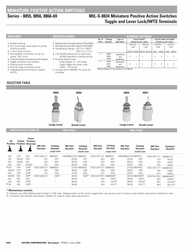
A60 EATON CORPORATION Aerospace TF300-5 June, 2004
SSEELLEECCTTIIOONN TTAABBLLEE88668868
Large Lever Small Lever Large Lever Small Lever
8869 8867
CIRCUIT WITH LEVER IN . . . ONE POLE TWO POLE
Up
Position
Center
Position
Down
Position
(Keyway)
ONONONON
*ONNONEONNONEONON
*ON
OFFNONENONEOFFOFFOFFOFFONONONON
ONOFFONNONEON*ON*ON*ON*ONON*ON*
MS21346-211-221-231-241
MS21346-271-281-311
MS21346-321---
MS21347-211-221-231-241
MS21347-271-281-311
MS21347-321-331-351-341
8869K51K57K54K55
8869K52K56K53
8869K581
K591
K5101
K5111
MS21347-711-721-731-741
MS21347-771-781-811
MS21347-821-831-851-841
8868K51K57K54K55
8868K52K56K53K581
---
8866K51K57K54K55
8866K52K56K53K581
---
8867K51K57K54K55
8867K52K56K53
8867K581
K591
K5101
K5111
MS24655-211W-221W-231W-241W-271W-281W-311W-321W-331W-351W-341W
8869K51XK57XK54XK55X
8869K52XK56XK53X
8869K58X1
K59X1
K510X1
K511X1
MS Part
Number
MS Part
NumberMS Part
Number
Catalog
Number
Large Lever Small Lever Small Lever
Catalog
Number Catalog2Number
* Momentary contact.
1 Dielectric per MIL-S-8834 except limited to 1250 volts. Delayed action of the switch toggle lever may cause circuit to close or open before snap action mechanism trips.2 Furnished with Bonded Seal feature. (Meets 15' head of water level requirement.)
No. of Poles
Catalog Number
Type of Operation
28VDC 50VDC 28VDC 50VDC 60Hz 400Hz 60Hz 400Hz
Minimum Rating: 25 microamperes at 5 millivolts.
8855 8866 8868
1 Maintained and
Momentary
28 and 50VDC (Amperes per pole)
115VAC 60Hz and 400Hz (Amperes per pole)
Resistive Load
Inductive Load
Resistive Load
Inductive Load
15 1 1
2 3
- 2 3
1 2
2
2 8856 8867 8869
Maintained and
Momentary5 1 1 -
MINIATURE POSITIVE ACTION SWITCHESSeries - 8855, 8856, 8866-69 MIL-S-8834 Miniature Positive Action Switches
Toggle and Lever Lock/IWTS Terminals
FFEEAATTUURREESS
• Sealed bushing• Dry circuit (logic level loads) to power
switching levels• 1 and 2 pole circuitry• Non-teasible mechanism for all but
center "ON" circuit• Small and large size bushings and Actuator• Toggle and lever lock Actuator• Wiping action contacts• Positive make and break action• Integrated Wire Termination System
(IWTS)
SSPPEECCIIFFIICCAATTIIOONNSS
• Bushing seal or bonded seal per MIL-S-8834• MS approved and QPL listed to MIL-S-8834• Temperature Range: -67°F to +160°F
(-55°C to +71°C)• Life:20,000 operations at rated load
40,000 operations mechanical life• Bushing thread sizes:
Small Toggle: ¼" - 40 threadLarge Toggle and Lever Lock: 15/32" - 32 thread
• Accepts MIL-C-39029/1 Pin (pins not included)
CCUURRRREENNTT RRAATTIINNGGSS
Large Lever
8868 8866 8869 8867
MS Part
Number
MS24656-211W-221W-231W-241W-271W-281W-311W-321W-331W-351W-341W
Catalog
Number
MS Part
Number
Catalog
Number

EATON CORPORATION Aerospace TF300-5 June, 2004 A61
SSEELLEECCTTIIOONN TTAABBLLEE
88568855
CIRCUIT WITH LEVER IN . . .
Up
PositionCenter
Position
Down
Position
(Keyway)
ONONONONONONONON
* ONON
* ONONNONEONON
OFFOFFOFFNONENONEOFFNONENONEOFFOFFOFFOFFOFFOFFOFF
ONONNONEOFFONONOFFONON*ON*ON*NONEON*ON*ON*
MS21346-A211-B211-B241-C221-C231
MS21346-D211-E221-E231-F271-G311
MS21346-H271-J241-K281-K311-L311
ABBCCDEEFGHJKKL
MS21347-A211-B211-B241-C221-C231
MS21347-D211-E221-E231-E271-G311
MS21347-H271-J241-K281-K311-L311
8856K54K55 K519K513K57
8856K510K514K58K515K516
8856K517K59K518K520K512
8855K54K55K519K513K57
8855K510K514K58K515K516
8855K517K59K518K520K512
MS Part
Number
Lever Lock
Bushing
Style
MS Part
Number
Catalog
Number
Catalog
Number
* Momentary contact.
Indicates direction against which lever is locked.See page A75 for special circuit diagrams.
TWO POLEONE POLE
LOCKING RING
0.480[12,19]
DIA. HOLE
0.37
5[9
,52]
0.130[3,30]
0.44
5[1
1,30
]
0.062[1,57]
KEYWAY
0.480[12,19] DIA. HOLE
MINIATURE POSITIVE ACTION SWITCHESSeries - 8855, 8856, 8866-69 MIL-S-8834 Miniature Positive Action Switches
Toggle and Lever Lock/IWTS Terminals
OOPPTTIIOONNSS//AACCCCEESSSSOORRIIEESS
• Special mounting hardware• Special marking• Mounting hardware furnished
assembled• Panel seal, Part Number 32-341
(15/32" - 32 bushing only)• Special circuits• Special bushing and lever finish• Special locking cap style on lever
lock switches• EMI/RFI capability on two pole
(15/32" - 32 bushing only)
LLEEVVEERR LLOOCCKK -- BBUUSSHHIINNGG SSTTYYLLEESS
PPAANNEELL CCUUTTOOUUTT DDIIMMEENNSSIIOONNSS
LOCKED OUT OFSIDE OPPOSITE
KEYWAY MOMENTARYEITHER SIDE
LOCKED OUT OFAND INTO SIDE
OPPOSITEKEYWAY
LOCKED IN CENTERPOSITION, MOMENTARY
LOCKED OUT OFSIDE OPPOSITE
KEYWAY, MOMENTARYKEYWAY SIDE
LOCKED IN 3POSITIONS
LOCKED INCENTERPOSITION
LOCKED INKEYWAY SIDE
LOCKED OUT OFSIDE OPPOSITE
KEYWAY
LOCKED OUTCENTER
POSITION
LOCKED IN CENTERPOSITION, MOMENTARY
EITHER SIDE
LOCKED OUT OFKEYWAY SIDEMOMENTARYKEYWAY SIDE
A B C D E F G
H J K L
KEYWAY SIDE
KEYWAY SIDE
2.57[6,53] DIA. HOLE
0.270[6,86]
.062 [1,57} MAX.THICK PANEL
15/32 DIA. BUSHING

A62 EATON CORPORATION Aerospace TF300-5 June, 2004
Lever Lock
Large Toggle/ Terminal Identification
Mounting dimensions for reference only.
.660[16,76] MAX
1.26
0[3
2,00
]
.030
[0,7
6]
MAX
.468
[11,
89]
.438
[11,
13]
THR
EAD
S
15/32-32 UN-2A THREAD
.072 [1,83]
.432[10,97]
1.04
9 [2
6,64
]U
NLO
CKE
D
.983
[24,
97]
LOC
KED
26°13°
.430[10,92] DIA.
.480
[12,
19]
.160[4,06]
.040[1,02]
.160[4,06]
.040
[1,0
2]
.460
[11,
68]
123 MAX
.660[16,76]
.160[4,06]
90-4579.AI
.040[1,02]
.160[4,06]
.040
[1,0
2]
MAX
.460
[11,
68]
123 MAX
1.26
0[3
2,00
]
.030
[0,7
6]
MAX
.468
[11,
89]
.438
[11,
13]
THR
EAD
S
.687
[17,
45]
14 28
15/32-32 UN-2A THREAD
.072 [1,83]
.432[10,97]
.240[6,10]
DIA.
.660[16,76]
.160[4,06]
90-4794.AI
.040[1,02]
.160[4,06]
.040
[1,0
2]
MAX
.460
[11,
68]
123 MAX
1.32
0[3
3,53
]
.028
[0,7
1]
MAX
.170
[4,3
2].0
48[1
,22]
.440
[11,
18]
21 42
.286[7,26].020
[0,51]
.045
[1,1
4].0
10[0
,25]
.093 [2,36]
DIA.
.125[3,18]
LOCKING TAB
1/4 - 40 UNS-2ATHREAD
.067[1,70]
.660[16,76]
90-4796.AI
MAX
1.32
0[3
3,53
]
.028
[0,7
1]
MAX
.170
[4,3
2].0
48[1
,22]
.440
[11,
18]
21 42
.286[7,26].020
[0,51]
.045
[1,1
4].0
10[0
,25]
.093 [2,36]
DIA.
.125[3,18]
LOCKING TAB
1/4 - 40 UNS-2ATHREAD
.067[1,70]
.160[4,06]
.040[1,02]
.160[4,06]
.270
[6,8
6]
.660
[16,
76]
123
456
MAX
.660[16,76]
.160[4,06]
90-4692.AI
.040[1,02]
.160[4,06]
.270
[6,8
6]
MAX
.660
[16,
76]
123
456
MAX
1.26
0[3
2,00
]
.030
[0,7
6]
MAX
.468
[11,
89]
.438
[11,
13]
THR
EAD
S
15/32-32 UN-2A THREAD
.072 [1,83]
.432[10,97]
1.04
9 [2
6,64
]U
NLO
CKE
D
.983
[24,
97]
LOC
KED
26°13°
.430[10,92] DIA.
.480
[12,
19]
Small Toggle Lever Lock
STANDARD0.00 = inches
[0,0] = mm
MINIATURE POSITIVE ACTION SWITCHESSeries - 8855, 8856, 8866-69 MIL-S-8834 Miniature Positive Action Switches
Toggle and Lever Lock/IWTS Terminals
MMOOUUNNTTIINNGG DDIIMMEENNSSIIOONNSS -- OONNEE PPOOLLEE // 88885555,, 88886666,, 88886688
MMOOUUNNTTIINNGG DDIIMMEENNSSIIOONNSS -- TTWWOO PPOOLLEE // 88885566,, 88886677,, 88886699
Small Toggle Large Toggle/ Terminal Identification

EATON CORPORATION Aerospace TF300-5 June, 2004 A63
SSEELLEECCTTIIOONN TTAABBLLEECIRCUIT WITH LEVER IN . . .
FOUR POLE
Up
Position
Center
Position
Down Position
(Keyway)
ONONONONON *NONEON NONEONONON *
OFFNONENONEOFFOFFOFFOFFONONONON
ONOFFONNONEON *ON *ON *ON *ONON *ON *
8854K1K7K4K5K2K6K3K8 1K9 1K101K111
Catalog
Number 2
* Momentary contact.
1 Dielectric per MIL-S-8834 except limited to 1250 Volts. Delayed action of the switch toggle lever may cause circuit to close or open before snap action mechanism trips.
2 Caution should be exercised during soldering and flux removal. See page A56 for details.
No. of
Poles
Catalog
Number
Type of
Operation
Resistive Load 28VDC
Inductive Load 28VDC
Resistive Load 60Hz 400Hz
Inductive Load 60HZ 400Hz
4 8854Maintained & Momentary 5 1 2 3 1 2
Minimum Rating: 25 microamperes at 5 millivolts or less.
28 and 50VDC (Amperes per pole)
115VAC 60Hz and 400Hz
(Amperes per pole)
MINIATURE POSITIVE ACTION SWITCHESSeries - 8854 4-Pole Miniature Positive Action Switch Series
FFEEAATTUURREESS• Made to MIL-DTL-8834 Requirements• Sealed bushing• Current rating versatility• 4 pole circuitry (Maintained &
Momentary variations)• Non-teasible mechanism for all but
center "on" position• Dry circuit (logic loads loads) to
power switching levels• Wiping action contacts• Positive make and break action• 11/16" Lever Length & 15/32" bushing
Dia.
• Solder-lug terminalsSS
SSPPEECCIIFFIICCAATTIIOONNSS• Bushing seal per MIL-DTL-8834• Meets 0.5" Head of Water• Temperature Range: -22°F to +149°F
-30°C to +65°C• Electrical Life: 20,000 Operations at
rated load• Mechanical Life:40,000 Operations
CCUURRRREENNTT RRAATTIINNGGSS

Terminal Identification
Mounting dimensions for reference only. Non-functional terminals not supplied.
.432 ± .000 .012
.0.72 ± .005KEYWAY
.240 ± .005
.687 ± .030
SPHERICAL RADIUS
15/32 (.469) -32 UNS-2A THREAD
(2PL) 15/32 (.469) -32 UNS-2B MTG NUT. HEX P/N: 15-966-6.469 LOCKWASHER, INT. TOOTH P/N: 15-886
.469 LOCKING RINGP/N: 29-761TERMINAL MARKING
.438 ± .025FULL THD.
.469
.030 MIN. WHEN MTG..706 MAX 1
1
SOLDER LUG WITH .045/.053 DIA. HOLE
1 110 MAX
28˚ ± 8˚
14˚ ± 4˚
MINIATURE POSITIVE ACTION SWITCHESSeries - 8854 4-Pole Miniature Positive Action Switch Series
MMOOUUNNTTIINNGG DDIIMMEENNSSIIOONNSS -- FFOOUURR PPOOLLEE // 88885544
STANDARD0.00 = inches
[0,0] = mm
A64 EATON CORPORATION Aerospace TF300-5 May, 2004
SOLDER.045/.0
1.110 MAX
21
11
.590 MAX
3 6 9 12

SSEELLEECCTTIIOONN TTAABBLLEE
Up
Position
Center
Position
Down
Position
(Keyway)
ONONONONONONONONONONONONONON *ONNONEON *NONEON *ONONONON *ONON
OFFOFFNONENONEOFFOFFOFFNONENONEOFFOFFOFFONONONONOFFOFFOFFONONONONONON
ONONONONNONEONON *OFFOFFON *NONEON *ONON *ON *ON *ON *ON *ON *ONONONON *ON *ON *
8879K74K75K77K78K79K710K712K713K714K716K719K720K721 1K722 1K723 1K724 1K727K728K729K730 1K731 1K732 1K734 1K735 1K736 1
Catalog2Number
* Momentary contact.
1 Dielectric per MIL-S-8834 except limited to 1250 Volts. Delayed action of the switch toggle lever may cause circuit to close or open before snap action mecha-nism trips.
2 Caution should be exercised during soldering and flux removal. See page A56 for details.
Resistive Load
28VDC
Inductive Load
28VDC Resistive Load 60Hz 400Hz
Inductive Load 60HZ 400Hz
4 8879
Maintained and Momentary 5 1 2 3 1 2
Minimum Rating: 25 microamperes at 5 millivolts or less.
115VAC 60Hz and 400Hz
(Amperes per pole)
28 and 50VDC
(Amperes per pole)
No. of
Poles
Catalog
Number
Type of
Operation
MINIATURE POSITIVE ACTION SWITCHESSeries - 8879 4-Pole Miniature Positive Action Switch Series
FFEEAATTUURREESS• Made to MIL-DTL-8834 Requirements• Sealed bushing• Current rating versatility• 4 pole circuitry (Maintained &
Momentary variations)• Non-teasible mechanism for all but
center "on" position• Dry circuit (logic loads loads) to
power switching levels• Wiping action contacts• Positive make and break action• Bullet and Mushroom Lever lock
Actuator styles • 12 Lever Locking configurations• 15/32" bushing Dia. • Solder-lug terminals ± Ø
SSPPEECCIIFFIICCAATTIIOONNSS• Bushing seal per MIL-DTL-8834• Meets 0.5" Head of Water• Temperature Range: -22°F to +149°F
-30°C to +65°C• Electrical Life:20,000 Operations at
rated load• Mechanical Life: 40,000 Operations
CCUURRRREENNTT RRAATTIINNGGSS
CIRCUIT WITH LEVER IN . . . FOUR POLE
EATON CORPORATION Aerospace TF300-5 May, 2004 A65

Terminal Identification
Mounting dimensions for reference only. Non-functional terminals not supplied.
STANDARD0.00 = inches
[0,0] = mm
MINIATURE POSITIVE ACTION SWITCHESSeries - 8879 4-Pole Miniature Positive Switch Series
MMOOUUNNTTIINNGG DDIIMMEENNSSIIOONNSS -- FFOOUURR PPOOLLEE // 88887799
MMOOUUNNTTIINNGG DDIIMMEENNSSIIOONNSS -- FFOOUURR PPOOLLEE // 88887799
.072 ± .005
.432 ± .000 .012
VIEW WITH LEVER LOCK REMOVED
Ø .430 MAX.
.480.983 ± .047LOCKED
.438 ± .025LOCKED.469
.706 MAX
TERMINAL MARKINGLOCATION OPTIONAL
SOLDER LUG WITH .045/.053 DIA. HOLE (12) PLACES .
15/32 (.469) -32 UNS-2A THREAD
.030 MIN. WHEN MTG.
26˚± 8 ̊13˚± 4 ̊
KEYWAY SIDEINTERNAL TOOTH WASHER EATON PT. NO. 16-886
LOCKING RINGEATON PT. NO. 29-761
(2) HEX. NUTEATON PT. NO. 15-966-6
1
1
1 21
54
87
1110
3 6 9 12
1.110 MAX
.590 MAX
.432 ± .000 .012
.072 ± .005
VIEW WITH LEVER LOCK REMOVED
Ø .430 MAX.
29˚± 8 ̊14˚± 4 ̊
1.122 ± .040LOCKED
.469
.438 ± .025THREADS
.706 MAX.
15/32 (.469) -32 UNS-2A THREAD
.030 MIN. WHEN MTG.
TERMINAL MARKINGLOCATION OPTIONAL
SOLDER LUG WITH .045/.053 DIA. HOLE (12) PLACES
1.110 MAX
.590 MAX
21
54
87
1110
3 6 9 12
(2) HEX. NUTEATON PT. NO. 15-966-6 1
LOCKING RINGEATON PT. NO. 29-761
1
KEYWAY SIDEINTERNAL TOOTH WASHER EATON PT. NO. 16-886
1
A66 EATON CORPORATION Aerospace TF300-5 May, 2004

EATON CORPORATION Aerospace TF300-5 June, 2004 A67
T2153 T3113T2114
SSeerriieess TTWW ((SSeeaalleedd))
TW20000 TW20002 TW20001 TW1003
Catalog
Number
Poles
and
Throw
T1002 1 P.S.T. 5 20 15 3 10 10T1003 1 P.D.T. 5 20 15 3 10 10T2106 1 P.D.T.* — 10 5 — 10 5T2114 1 P.D.T.* — 10 5 — 10 5T2150 2 P.D.T. — 3 1 — 3 1T2153 2 P.D.T. — 3 1 — 3 1T3103 1 P.D.T. — 5 3 — 5 3T3113 1 P.D.T. — 5 3 — 5 3
*Two Circuit
28VDC 115 VAC
Resistive Load (Amps)
Inductive Load (Amps) (.75
Lamp Load (Amps)
Resistive Load (Amps)
Inductive Load (Amps)
Lamp Load
Catalog
Number
MS
Number1
Poles
and
Throw
TW1002 — 1 P.S.T. 5 20 15 3 10 10TW1003 — 1 P.D.T. 5 20 15 3 10 10TW20000 — 2 P.D.T. .5* 2 .5* .1 .1 .1TW20001 — 1 P.D.T.* .5 2 .5 .1 .1 .1TW20002 MS18151-1 1 P.D.T. .5 1 .5 .1 .1 .11
Qualified to MIL-S-83731 *Two Circuit
28VDC 115 VAC
Lamp Load
Resistive Load
Inductive Load
Lamp Load
Resistive Load
Inductive Load (Amps)
MINIATURE INTEGRAL TOGGLE SWITCHESSeries T and TW T 2150, TW 20,000, T 2660, TW 20,001
SSeerriieess TTSSPPEECCIIFFIICCAATTIIOONNSS
• Seal: Dust resistant• Type of Operation: Maintained• Electrical Life: 10,000 operations at
28VDC or 115VAC• Mechanical Life: 20,000 operations• Operating Temp. Range: -85°F to +160°F
(-65°C to +71°C)
CCUURRRREENNTT RRAATTIINNGGSS
SSPPEECCIIFFIICCAATTIIOONNSS
• Seal: Dust proof (per MIL-S-83731)• Type of Operation: Maintained• Electrical Life: 20,000 operations at
28VDC or 115VAC• Mechanical Life: 40,000 operations• Operating Temp. Range: -40°F to +160°F
(-40°C to +71°C)
CCUURRRREENNTT RRAATTIINNGGSS
NOTE: For specific drawing dimensions, contact factory at 1-800-955-7354.

A68 EATON CORPORATION Aerospace TF300-5 June, 2004
No. of Poles
Catalog Number
Type of Operation
12 80 30 7.5 30 203 8790K4 8792K3
Maintained
28VDC 115 VAC
60 or 400HzLamp Load
Resistive Load
Inductive Load
Lamp Load
Resistive Load
Inductive Load
8780K11 8781K11 8782K11
1 Maintained 35 175 45 11 55 45
SSEELLEECCTTIIOONN TTAABBLLEE
8780
8790
CIRCUIT WITH LEVER IN . . .
One Pole - High Capacity
Up
Position
Center
Position
Down Position
(Keyway)
ONONON
OFFNONENONE
ONOFFON
AN3230-1-2-3
———
8780K118781K118782K11
AN Part
Number
MS or Government
Drawing Number
Catalog
Number
ONON
——
ONON
OFFNONE
E1663-1-3
8790K48792K3
Three Pole - High Capacity
HIGH CAPACITY SWITCHESSeries - 8780-82, 8790 & 8792 High Capacity Flush Mounted Switches
FFEEAATTUURREESS
• 1 and 3 pole circuitry• Flush mounted (5 holes required)• High capacity ratings• Terminal stud termination
SSPPEECCIIFFIICCAATTIIOONNSS
• Military approved to MIL-S-3950C and E1663 specifications
• Current ratings up to 175 Amp on AN3230 type and 80 Amp on E1663 type
• Temperature Range: -67°F to +160°F(-55°C to +71°C)
• Life: 10,000 operations at rated load20,000 operations mechanical life
• Power studs have .250” [6,35] -20 threads
CCUURRRREENNTT RRAATTIINNGGSS

EATON CORPORATION Aerospace TF300-5 June, 2004 A69
Terminal Identification
Terminal Identification
Mounting dimensions for reference only. Non-functional terminals not supplied.
3.265[82,93]
2.75[69,85]
1.05
[38,
10]
2.02
[51,
31]M
AX
MAX4-#8-32LOCKINGNUT
D FLAT.125
[3,1
8]2.
938
[74,
63]
.750
[19,
05]
1.06[26,9]
1.06[26,9]
1/4-20 STUDS
50̊
25̊
1.68
7[4
2,85
]
MAX.687[17,45]
1.50
5[3
8,10
]
2.37
5[6
0,33
]
2.755[69,98]
.656[16.66]
1.70
[43,
2]2.
84[7
2,1]
MAX
3.125[79,38]
.2.5
364
,26]
1/4-20 THR’D2.34
[59,4]
48˚
24˚
#8-32 TAP-4MTG HOLES
INSULATOR MAY EXTENDBEYOND COVER BY .032 [0,81]
STANDARD0.00 = inches
[0,0] = mm
HIGH CAPACITY SWITCHESSeries - 8780, 8790 High Capacity Flush Mounted Switches
MMOOUUNNTTIINNGG DDIIMMEENNSSIIOONNSS -- OONNEE PPOOLLEE // 88778800,, 88778811,, 88778822
MMOOUUNNTTIINNGG DDIIMMEENNSSIIOONNSS -- TTHHRREEEE PPOOLLEE // 88779900,, 88779922

A70 EATON CORPORATION Aerospace TF300-5 June, 2004
C NO NC
CNONC
C
NO NC
C
NONC
C NO NC
CNONC
C NO NC
CNONC
C NO NC
CNONC
C NO NC
CNONC
C NO NC
CNONC
C NO NC
CNONC
C NO NC
CNONC
C NO NC
CNONC
C NO NC
CNONC
C
NO NC
C
NO NC
C
NONC
C
NONC
C
NO NC
C
NO NC
C
NONC
C
NO NC
C
NONC
C
NONC
C
NO NC
C
NO NC
C
NONC
C
NO NC
C
NONC
C
NO NC
C
NONC
C
NONC
POSITION #1("D" FLAT)
POSITION #2(CENTER)
POSITION #3(OPPOSITE)
C
C
1
2
NO
NO
NC
NC
C
C
1
2
NO
NO
NC
NC
C
C
1
2
NO
NO
NC
NC
C1
C2
NONC
NC
C3
C4
NONC
NC
NO NO
C1
C2
NONC
NC
C3
C4
NONC
NC
NO NO
C1
C2
NONC
NC
C3
C4
NONC
NC
NO NO
C1
C2
NONC
NC
C4
C3
NONC
NC
NO NO
C1
C2
NONC
NC
C4
C5
NONC
NC
NO NO
C1
C2
NONC
NC
C4
C5
NONC
NC
NO NO
C3
NC
C6
NC
NO NOC
3
NC
C6
NC
NO NOC
3
NC
C6
NC
NO NO
C1
C3
NONC
NC
C5
C5
NONC
NC
NO NO
C1
C2
NONC
NC
C5
C6
NONC
NC
NO NO
C1
C2
NONC
NC
C5
C6
NONC
NC
NO NO
C3
NC
C7
NC
NO NOC
3
NC
C7
NC
NO NOC
3
NC
C7
NC
NO NO
C4
NC
C8
NC
NO NOC
4
NC
C8
NC
NO NOC
4
NC
C8
NC
NO NO
Switch #1
Switch #2
Switch #1
Switch #2
Switch #3
Switch #4
Switch #1
Switch #2
Switch #4
Switch #5
Switch #3 Switch #6
Switch #1
Switch #2
Switch #5
Switch #6
Switch #3 Switch #7
Switch #4 Switch #8
2 Pole2 Pole
4 Pole4 Pole
6 Pole6 Pole
8 Pole8 Pole
NOMINAL RATINGS AND CIRCUIT DIAGRAMS
BBAASSIICC SSWWIITTCCHH CCIIRRCCUUIITTSS BBAACCKK CCOONNFFIIGGUURRAATTIIOONNSS SSCCHHEEMMAATTIICC DDIIAAGGRRAAMMSS
3 Phase
Catalog Number 125VAC 250VAC 125VAC 250VAC 125/250VAC
8520K1, K4, K9 18 9 1/4 1/2 —8521K1, K4, K9 18 9 1/2 1 —8522K1, K4, K9 18 9 1/2 1 18526K2, K3, K5 18 9 — — —8527K2, K3, K5 18 9 — — —
8528K2, K3, K5 18 9 — — —8530K1-13,K31-313,K91-913 18 9 1/4 1/2 —8531K1-16,K31-316,K91-916 18 9 1/2 1 —8532K1-17,K31-317,K91-917 18 9 1/2 1 18533K1-13,K31-313,K91-913 18 9 1/4 1/2 —
8534K1-13,K31-316,K91-916 18 9 1/2 1 —8535K1-17,K31-317,K91-917 18 9 1/2 1 18536K1-13,K31-313,K91-913 18 9 1/4 1/2 —8537K1-16,K31-316,K91-916 18 9 1/2 1 —8538K1-17,K31-317,K91-917 18 9 1/2 1 1
Amperes
Maximum Horsepower
1 Phase
UULL AANNDD CCSSAA NNOOMMIINNAALL RRAATTIINNGGSS
Standard Sealed
2 Pole
4 Pole
6 Pole
8 Pole

1 2 3
1 2 3
1 2 3
1 2 3
NONEOFF
OFF(MOM.)OFF
NONENONE
NONE
OFFNONENONE
OFF
OFF(MOM.)321
321
EATON CORPORATION Aerospace TF300-5 June, 2004 A71
Up
Position
Switch
Circuit1
Number of
Poles and
Throws
Center
Position
Down Position
(Keyway)
ON-NONE-OFF
ON-OFF-NONE
ON-OFF*-NONE
NONE-OFF-ON*
ON-NONE-OFF*
OFF-NONE-ON*
ON-OFF-ONON-NONE-ONON-NONE-ON*
*ON-OFF-ON*
ON-OFF-ON*
*ON-ON-NONEON-ON-NONE
ON-NONE-OFF
ON-OFF-NONE
ON-OFF*-NONE
NONE-OFF-ON*
ON-NONE-OFF*
OFF-NONE-ON*
ON-OFF-ON
ON-NONE-ON
ON-NONE-ON*
*ON-OFF-ON*
ON-OFF-ON*
*ON-ON-NONE
ON-ON-NONE
ON-NONE-OFF
ON-OFF-NONE
ON-OFF*-NONE
NONE-OFF-ON*
ON-NONE-OFF*
OFF-NONE-ON*
1PST
1PDT
2PST
2PDT
4PST
CIRCUIT WITH LEVER IN . . .
TOGGLE SWITCHES - ENVIRONMENTALLY SEALED SWITCHESStandard Circuit Arrangements Industrial, Econoswitch and MIL-S-3950 Series
* Momentary Contact
321
1 2 3
1 2 3
1 2 3
1 2 3
1 2 3
1 2 3
1 2 3 321
321
321
321
321
321321
NONENONEOFFOFF
NONENONE
4 5 6
1 2 3
1 2 3
4 5 6
1 2 3
4 5 6
OFF
OFF(MOM.) NONE
OFF(MOM.)
NONE OFF
NONE
NONE
OFF
1 2 3
4 5 6
OFF
NONE
NONE 321
654
321
654
4 5 6
1 2 3
1 2 3
4 5 6
1 2 3
4 5 6
NONE
NONE
NONE
1 2 3
4 5 6
321
654
1 2 3
4 5 6
1 2 3
4 5 6
1 2 3
4 5 6
NONE
321
654
321
654
321
654
321
654
321
654
321
654
321
654
321
654
321
654
4 5 6
1 2 3
7 8 9
10 11 12
NONE
OFF
NONE
321
NONE
654
NONE OFF
OFF(MOM.)
987
121110
OFF(MOM.)NONE
NONE
4 5 6
1 2 3
7 8 9
10 11 12
4 5 6
1 2 3
7 8 9
10 11 12
OFF
4 5 6
1 2 3
7 8 9
10 11 12
321
654
987
121110
OFF

A72 EATON CORPORATION Aerospace TF300-5 June, 2004
Up
Position
Switch
Circuit1
Number of
Poles and
Throws
Center
Position
Down Position
(Keyway)
ON-OFF-ON
ON-NONE-ON
ON-NONE-ON*
*ON-OFF-ON*
ON-OFF-ON*
*ON-ON-NONE
ON-ON-NONE
4PDT
CIRCUIT WITH LEVER IN . . .
1 See page A75 for ON-ON-ON and special circuits.
* Momentary contact.
TOGGLE SWITCHES - ENVIRONMENTALLY SEALED SWITCHESStandard Circuit Arrangements Industrial, Econoswitch and MIL-S-3950 Series
4 5 6
1 2 3
7 8 9
10 11 12
OFF
NONE
321
654
NONE
987
121110
4 5 6
1 2 3
7 8 9
10 11 12
4 5 6
1 2 3
7 8 9
10 11 12
4 5 6
1 2 3
7 8 9
10 11 12
OFF
OFF4 5 6
1 2 3
7 8 9
10 11 12
4 5 6
1 2 3
7 8 9
10 11 12
4 5 6
1 2 3
7 8 9
10 11 12
NONE
NONE321
654
987
121110
321
654
987
121110
321
654
987
121110
321
654
987
121110
321
654
987
121110
321
654
987
121110

EATON CORPORATION Aerospace TF300-5 June, 2004 A73
Circuit with Lever in . . .
TWO POLE
Up
Position
Center
Position
Down Position
(Keyway)
2
2
2
2
2
2
4
4
4
8501K14, 8504K43-K55, 8511K148531K14, 8531K914, 8531K3148534K14, 8534K914, 8534K3148537K14, 8537K914, 8537K314, 8567K14
8501K15, 8504K56-K61, 8511K158531K15, 8531K915, 8531K3158534K15, 8534K915, 8534K3158537K15, 8537K915, 8537K315, 8567K15
8501K16, 8504K62-K64, 8511K168531K16, 8531K916, 8531K3168534K16, 8534K916, 8534K3168537K16, 8537K916, 8537K316, 8567K16
8501K17, 8504K65-K77, 8511K178531K17, 8531K917, 8531K3178567K17, 8571K17-16, 8571K17-208574K65-16 - 8574K77-168574K65-20 - 8574K77-20
8501K18, 8504K78-K83, 8511K188531K18, 8531K918, 8531K3188567K18, 8571K18-16, 8571K18-208574K78-16 - 8574K83-168574K78-20 - 8574K83-20
8501K19, 8504K84-K87, 8511K198531K19, 8531K919, 8531K3198567K19, 8571K19-16, 8571K19-208574K84-16, 8574K86-168574K84-20, 8574K86-20
8502K15, 8512K158532K15, 8532K915, 8532K3158535K15, 8535K915, 8535K3158538K15, 8538K915, 8538K3158568K158575K43-16 - 8575K55-168575K43-20 - 8575K55-20
8502K16, 8512K168532K16, 8532K916, 8532K3168535K16, 8535K916, 8535K3168538K16, 8538K916, 8538K3168568K168575K56-16 - 8575K61-168575K56-20 - 8575K61-20
8502K17, 8512K178532K17, 8532K917, 8532K3178535K17, 8535K917, 8535K3178538K17, 8538K917, 8538K3178568K178575K62-16 - 8575K64-168575K62-20 - 8575K64-20
Number of
Poles Catalog Part Number
FOUR POLE
1 2 3
4 5 6
Maintained
1 2 3
Maintained Maintained Maintained
1 2 3
654
321
654
1 2 3
4 5 6
Maintained
1 2 3
Maintained Maintained Momentary
1 2 3
654
321
654
1 2 3
4 5 6
Momentary
1 2 3
Maintained Momentary
1 2 3
654
321
654
1 2 3
Maintained
1 2 3
Maintained Maintained Maintained
1 2 3
654
321
654
1 2 3
Maintained
1 2 3
Maintained Maintained
1 2 3
654
321
654
1 2 31 2 3
Maintained
1 2 3
654
321
654
1 2 3
4 5 6
Maintained
1 2 3
Maintained Maintained Maintained
321
654
1 2 3
Maintained
1 2 3
Maintained Maintained Maintained
321
6544 5 6
TOGGLE SWITCHES - ENVIRONMENTALLY SEALED SWITCHESSpecial ON-ON-ON Circuit Arrangements for Two and Four Pole Switches
Industrial, Econoswitch and MIL-S-3950 Series
1 2 3
4 5 6
Maintained
1 2 3
Maintained Maintained Momentary
321
654
1 2 3
Maintained
1 2 3
Maintained Maintained
321
6544 5 6
1 2 3
4 5 6
Momentary
1 2 3
Maintained Momentary
321
654
1 2 31 2 3
Maintained
321
6544 5 6
1 2 3
4 5 6
Maintained
1 2 3
Maintained Maintained Maintained
1 2 3
654
321
654
1 2 3
Maintained
1 2 3
Maintained Maintained Maintained
1 2 3
654
321
654
1 2 3
11
1 2 3
10 12
987
121110
7 8 9 987
10 11 12
1 2 3
4 5 6
Maintained
1 2 3
Maintained Maintained Momentary
1 2 3
654
321
654
1 2 3
Maintained
1 2 3
Maintained Maintained
1 2 3
654
321
654
7 8 9
11
987
121110
987
10 11 12
1 2 3
4 5 6
Momentary
1 2 3
Maintained Momentary
1 2 3
654
321
654
1 2 31 2 3
Maintained
1 2 3
654
321
654
7 8 9
1110 12
987
121110
987
10 11 12
10 12

A74 EATON CORPORATION Aerospace TF300-5 June, 2004
Up
Position
No. of
Poles
Circuit
Poles
Connection Points Single Pole1 Double Pole2
Down
Position
(Keyway)
1
2
Connect Common to Terminals
Connect Circuit "A" to Terminals
Connect Circuit "B" to Terminals
Connect Circuit "C" to Terminals
2
6
4
1
2 and 11
6 and 9
4 and 7
1 and 10
"Three Independent" ON-ON-ON Circuit DiagramFor switch modified with "Three Independent" ON-ON-ON Special Circuit.External Jumpers are required. User to connect wiring per instructions given below.
Circuit for Single Pole(Jumper between Terminals #3 & #5)
Circuit for Double Pole(Jumpers between Terminals #3 & #5
#8 & #12)
1 Requires using a two pole switch to accomplish single pole independent "on-on-on" circuit.2 Requires using a four pole switch to accomplish a double pole independent "on-on-on" circuit.Note: Basic circuit same as offered with part numbers 8501K14, 8501K15 or 8501K16 for two pole devices and part numbers 8502K15, 8502K16 or 8502K17 for four pole devices.
1 2 3
4 5 6
1 2 3
4 5 6 4 5 6
1 2 3
1 2 3
4 5 6
1 2 3
4 5 6 4 5 6
1 2 3
7 8 9 7 8 8 7 8 9
Up
Position
No. of
Poles
Circuit Center
Maintained
Position
Down
Position
(Keyway)
Circuit Being
Made . . .
Terminal Numbers
Making the Circuit
2
4
Note: Requires two poles to achieve asingle pole device or four poles toachieve a double pole device.
Circuit for Single Pole (Jumper between terminals #2 & #4).Common terminal #5.Non-functional terminal #6
UP (OFF)
CENTER (ON)
DOWN (ON)
UP (OFF)
CENTER (ON)
DOWN (ON)
—
#3 & #5
#1 & #5
—
#3 & #5#8 & #12
#1 & #5#8 & #10
Circuit for Double Pole(Jumpers between terminals #2 & #4and #7 & #11).Common terminals #5 & #8.Non-functional terminals #6
1 2 3
4 5 6
1 2 3
4 5 6 4 5 6
1 2 3
1 2 3
4 5 6
1 2 3
4 5 6 4 5 6
1 2 3
7 8 9
10 11 12
7 8 8
10 11 12 10 11 12
7 8 9
(ON)(OFF) (ON)
7 8 9
10 11 12
7 8 8
10 11 12 10 11 12
7 8 9
(ON)(OFF) (ON)
Center
Maintained
Position
Up
Position
No. of
Poles
Circuit Center
Maintained
Position
Down
Position
(Keyway)
Circuit Being
Made . . .
Terminal Numbers
Making the Circuit
2
4
Note: Requires two poles to achievea single pole device or four poles toachieve a double pole device.
Circuit for Single Pole(Jumper between terminals #2 & #5).Common terminal #5.Non-functional terminal #1 & #4.
UP (ON)
CENTER (ON)
DOWN (OFF)
UP (ON)
CENTER (ON)
DOWN (OFF)
#2 & #3#5 & #6#5 & #3
—
#5 & #3#5 & #6#8 & #12#8 & #9
Circuit for Double Pole(Jumpers between terminals #2 & #5and #8 & #11).Common terminals #5 & #8.Non-functional terminals #1,#7 & #9.
(ON)(ON) (OFF)
1 2 3
4 5 6
1 2 3
4 5 6 4 5 6
1 2 3
1 2 3
4 5 6
1 2 3
4 5 6 4 5 6
1 2 3
7 8 9
10 11 12
7 8 8
10 11 12 10 11 12
7 8 9
(ON)(ON) (OFF)
TOGGLE SWITCHES - ENVIRONMENTALLY SEALED SWITCHESSpecial Circuit Arrangements for Two and Four Pole Switches Industrial, Econoswitch and MIL-S-3950 Series
SSPPEECCIIAALL ""OONN--OONN--OONN"" CCIIRRCCUUIITT AARRRRAANNGGEEMMEENNTTSS
SSPPEECCIIAALL CCIIRRCCUUIITT ((OOFFFF--OONN--OONN))
SSPPEECCIIAALL PPRROOJJEECCTTOORR CCIIRRCCUUIITT ((OOFFFF--OONN--OONN))
OOFFFF OONN OONN
OOFFFF OONN OONN
#3 & #5#8 & #12
—

EATON CORPORATION Aerospace TF300-5 June, 2004 A75
Up
Position
No. of
Poles
Circuit
Poles
Connection Points Single Pole1
Down
Position
(Keyway)
1
Connect Common to Terminals
Connect Circuit "A" to Terminals
Connect Circuit "B" to Terminals
Connect Circuit "C" to Terminals
2
6
4
1
"Three Independent " ON-ON-ON Circuit DiagramFor switch modified with "Three Independent" ON-ON-ON Special Circuit.External Jumpers are required. User to connect wiring per instructions given below.
Circuit for Single Pole(Jumper between Terminals #3 & #5)
Center
Maintained
Position
CIRCUIT WITH LEVER IN . . .
Two Pole
Up
Position
Center
Position
Down Position
(Keyway)
Maintained Maintained Maintained2
2
2
8856K21, K30, K31, K328856K21X, K30X, K31X, K32X8856K721, K730, K731, K7328867K9, 8867K69, 8867KA698869K9, 8869K9X, 8869K69, 8869K69X
8856K23, K35, K368856K23X, K35X, K36X8856K723, K735, K7368867K10, 8867K610, 8867KA6108869K10, 8869K10X, 8869K610,8869K610X8856K22, K348856K22X, K34X8856K722, K7348867K11, 8867K611, 8867KA6118869K11, 8869K11X, 8869K611,8869K611X
Number of
Poles Catalog Part Number
1 2 3
1 2 3
1 2 3
4 5 6 4 5 6
1 2 3
SPECIAL ON-ON-ON CIRCUITS FOR Miniature POSITIVE ACTION SWITCHESCircuit Arrangements
SSPPEECCIIAALL ""OONN--OONN--OONN"" CCIIRRCCUUIITT AARRRRAANNGGEEMMEENNTTSS
Maintained Maintained Momentary
Maintained Maintained Momentary
1 2 3
1 2 3
1 2 3
4 5 6 4 5 6
1 2 3
1Requires using a two pole switch to accomplish single pole Independent "ON-ON-ON" circuit.
1 2 3
1 2 3
1 2 3
4 5 6 4 5 6
1 2 3
1 2 3
1 2 3
1 2 3
4 5 6 4 5 6
1 2 3

A76 EATON CORPORATION Aerospace TF300-5 June, 2004
NOTES

EATON CORPORATION Aerospace TF300-5 June, 2004 B1
Index B-1
Standard Pushbutton Switches B2 - B14• Momentary and alternate action• Ratings up to 40 amperes• One and two pole configurations• Single hole mounting• Decorative Actuator in various colors• Two moisture proof series
Uniform Panel Appearance (UPA) Pushbutton Switches B15 - B17
• Ratings up to 10 amperes• One, two and four pole configurations• Solder lug or quick connect terminals• Momentary snap or push-pull action• Single hole mounting• RFI version available
Sub-Miniature Pushbutton Switches B18 - B19
• Snap action• MIL approved• Sealed or non-sealed• Low operating force
Illuminated Switches B20
• Momentary or alternate action• Ratings up to 2 amperes• Two pole and two circuit configurations• Single hole mounting• Most designed to use MS25237 type lamps
Hand Controls with Pushbutton Switches B21 - B23• Control stick mounting• Non "freeze" durable phenolic handle• Heavy duty trigger switch• Available with cord for remote operation• Available with auxiliary switch
Special Designed Pushbutton Switches B24 - B25
• Foot operated microphone switches• Mechanically actuated switches with lock feature• Switching mechanism sealed against dust and moisture• Rugged construction with flush mounting design
Pushbutton Switches IndexSECTION B
*Most items listed in this catalog are standard products and are normallyin Distributor Inventory; however, the current inventory status should bechecked by contacting your Eaton Customer Service Representative at800-955-7354 or your authorized Distributor before placing orders.

NO. 2
NO. 3
3/8 Diameter Typical
B2 EATON CORPORATION Aerospace TF300-5 June, 2004
SSEELLEECCTTIIOONN TTAABBLLEE
D201 1 Momentary 35 20 35 20D202 1 Momentary 35 20 35 20D203 1 Momentary 35 20 35 20D204 1 Momentary 15 — 15 —D205 1 Momentary 15 — 15 —
D207 1 Momentary 102
— 102
—1
p.f.=.752
3 amps max. through center terminal.
28VDC 115VAC
Part
Number
Number
of Poles Operation
Inductive
Load11
Resistive
Load
Inductive
Load11
Resistive
Load
• Catalog number of base switch - followed by suffix letters and numbers for type and color of case and pushbutton
D201 LB 5R = D201LB5R
Base CatalogNumber
Case Typeand Color
PushbuttonStyle
and Color
CompleteNumber
Base
Catalog
Number
D200 Series
D201L5 With Type
"L" Case
D201P3 With
Type "P" Case
D201W3 With
Type "W" Case
D201
D202
D203
1 P.S.T.-NO Dbl. Brk.
1 P.S.T.-NC Dbl. Brk.
1 P.D.T.-2 Ckt
Type "L"
Black
Clear
LB
L
NO. 5
5/16 Diameter Typical
5
5B
Chrome
Black
Circuit
Case and Type
and Color Code Suffiix Button Style
Pushbutton Style and Color
ColorCode
Suffiix
.44[11,13]
D204
D205
S.P.-NO 3 Terminal
S.P.-NC 3 Terminal
Type "P"
Black
Clear
PB
P
NO. 2
NO. 3
3/8 Diameter Typical
2R
2W
2
3R
3W
3
Red
White
Black
Red
White
Black
D207 S.P.-NO 4 Terminal Type "W"
Black
Clear
WB
W
2R
2W
2
3R
3W
3
Red
White
Black
Red
White
Black
.31[7,87]
PUSHBUTTON SWITCHESSeries - D200 Heavy Duty Momentary Snap Action Pushbutton Switches
FFEEAATTUURREESS
• High current carrying capability• Heavy duty pushbutton• Snap action mechanism• Minimal arcing and contact wear• Fast double break action• Variety of case styles and colors• Protective shields can be ordered sepa-
rately to prevent accidental actuation on "W" case model
• Black pushbutton supplied as standard
SSPPEECCIIFFIICCAATTIIOONNSS
• Operating force: 2.5 lbs ± .5 lb (11N ± 2.2N) D201 thru D205 4 lbs. ± 1 lb. (17.79N ± 4.45N) D207
• Electrical life: 25,000 operations minimum at rated load
• Total plunger travel (Approx.): 0.085 IN. (2.16mm), 0.438 IN. (11.12mm) with "L" Adapter
• Operating temperature: -40°F to +160°F (-40°C to +71°C)
• Momentary snap action• Terminals: End Screw (Center Terminal
Solder)• Weight: "W" case 0.040 lb. (18g)
"P" case 0.050 lb (23g)"L" case 0.045/ 0.055 lb (20g/25g)
CCUURRRREENNTT RRAATTIINNGGSS
WWHHEENN OORRDDEERRIINNGG SSPPEECCIIFFYY……
Order Example:
SSEERRIIEESS AANNDD TTYYPPEE
.31[7,87]
.25[6,35]
.25[6,35]

EATON CORPORATION Aerospace TF300-5 June, 2004 B3
D201 D202 D203 D204 D205 D207
Dimensions for reference only.
STANDARD0.00 = inches
[0,0] = mm
15/32 - 32NS-2A THD[11,91] DIA.
.31[7,8]
.44
[11,
1]
.50
[12,
7]
1.50
[38,
1]
.19[4,8]
.75[19,05]
TYPE "L" CASEAND #5 METALPLUNGER CAPCHROME STANDARDAND BLACKANODIZED AVAILABLE
.31[7,8]
.19[4,8]
7/8 - 27 NS - 2A THD[22,22] DIA.
.31[7,8]
.19[4,8]
1.00
[25,
4] .81
[20,
5]
1/2-32NS-2A THD[12,7]
.38[9,6]
.25[6,3]
.25[6,3]
.81
[20,
5]
.19[4,8]
.31[7,8]
.06 DIA. HOLE [1,5]
CENTER TERMINAL (D207 ONLY)
R G G R
(15 AMPERES MAX.) (15 AMPERES MAX.)
CENTER TERM.AMPS 10 MAX. (MAIN TERMINAL)
3 MAX. (CENTER TERMINAL)
PUSHBUTTON SWITCHESSeries - D200 Heavy Duty Momentary Snap Action Pushbutton Switches
AAPPPPRROOXXIIMMAATTEE DDIIMMEENNSSIIOONNSS -- DD220000 ""LL"" CCAASSEE AAPPPPRROOXXIIMMAATTEE DDIIMMEENNSSIIOONNSS -- DD220000 ""PP"" CCAASSEE
AAPPPPRROOXXIIMMAATTEE DDIIMMEENNSSIIOONNSS -- DD220000 ""WW"" CCAASSEE
BBAASSIICC SSWWIITTCCHH AANNDD SSCCHHEEMMAATTIICC DDIIAAGGRRAAMM

B4 EATON CORPORATION Aerospace TF300-5 June, 2004
• For switch with pushbutton only - specify catalog number of base switch fol -lowed by code for pushbutton color. Use code R for red and leave blank if black button is desired. Examples:
H 2 2 1 1 R
• For switch with mounting adapter - specify catalog number of base switch fol-lowed by suffix letters and numbers for type and color of adapter and pushbutton. Example:
H 2 2 6 6 P B 3 R
1 Clear anodized aluminum is standard. All threads are 1/2”-32 NS-2B internal: 5/8”-24 NEF-2A external except as noted. 2 The different pushbutton types are only available when using with one of the 4 different adapters.3 When used with any of these adapters the switch can be used as part of the UPA group of switches on pages B16 and B17.
Part
Number
H2211PB3 With Type
“P” Adapter
H2266 Without
Mounting
Adapter
H2211
H2222
2 P.S.T.-NO
Double Break
2 P.S.T.-NC
Double Break
TYPE P Black
Clear
PB
P
NO. 22R
2
Red
Black
Circuit Type Color Code Suffix ColorType2 Code Suffiix
H2211 2 Momentary 10 10H2222 2 Momentary 10 10H2266 2 Momentary 35 20
11 p.f.=.75
Catalog
Number
Number
of Poles
Type of
Operation
125VAC
Inductive11
28VDC
Inductive
SSEELLEECCTTIIOONN TTAABBLLEE
.875[22,22]
.063[1,60]
.188
[4,7
8]
DIA.
.500
[12,
70]
H2266 2 P.D.T.
Double Break
TYPE PA Black
Clear
PAB
PA
NO. 3 3R
3
Red
Black
.688[17,48]
.188[4,78]
.031[0,79]
.500[12,70]
DIA.
.500
[12,
70]
TYPE U Black
Clear
UB
U.063
[16,00]
.750[19,05]
.188[4,76]
.500
[12,
70]
TYPE W Black
Clear
WB
W
.875[22,22]
.063[16,00]
.063[16,00]
.500[12,70]
DIA.
.500
[12,
70]
Adapter Type1 and Color3 Pushbutton Type and Color
NO. 4 4R
4
Red
Black
BASIC SWITCH
BUTTON COLOR
BUTTON STYLE
ADAPTER COLOR
ADAPTER TYPE
BASE SWITCH AND CIRCUIT
PLUNGER COLOR
PUSHBUTTON SWITCHESSeries - H2200 Double Pole Momentary Snap Action Pushbutton Switches
FFEEAATTUURREESS• Double pole• Optional mounting adapters• Various styles and colors of pushbuttons• Solder terminals• Momentary snap action• Protective shields can be ordered
separately to prevent accidental actuation on "W" case model
• Black pushbutton supplied as standard• Other colors available
SSPPEECCIIFFIICCAATTIIOONNSS• Operating force: 5.5 ± 1.5 lbs (24.2N ± 6.6N)• Release force: 1 lb. minimum (.45g)• Electrical life: 25,000 operations
minimum at rated load• Terminals: Solder• Weight approx.: .05 lb. (.023g)
CCUURRRREENNTT RRAATTIINNGGSS
SSEERRIIEESS AANNDD TTYYPPEE
WWHHEENN OORRDDEERRIINNGG SSPPEECCIIFFYY……
.375
[9,53] DIA.
.313
[7,9
5].3
13[7
,95]
.375
[9,53] DIA.
.375
[9,53] DIA.
1.88[4,76]

EATON CORPORATION Aerospace TF300-5 June, 2004 B5
Dimensions for reference only.
STANDARD0.00 = inches
[0,0] = mm
PUSHBUTTON SWITCHESSeries - H2200 Double Pole Momentary Snap Action Pushbutton Switches
AAPPPPRROOXXIIMMAATTEE DDIIMMEENNSSIIOONNSS -- HH22220000
BBAASSIICC SSWWIITTCCHH AANNDD SSCCHHEEMMAATTIICC DDIIAAGGRRAAMM
D.P.S.T. NORMALLY OPEN
H2211D.P.S.T. NORMALLY CLOSED
H2222D.P.D.T.
H2266
.312
[7,9
4]
.437
[11,
10]
(TYP
.)
1.43
7[3
6,51
]
.375[9,53]
.070 DIA. HOLES (TYP.)
VIEW WITH ADAPTER ANDAUXILIARY BUTTONREMOVED
TYPE 3 AUXILIARYPLUNGER CAPIF USED
.25
[6,3
]
.187
[4,76
]
.165
[4,1
9]
1.0[25,40]
.625
[15,
88]
13
64 .25
[6,35](TYP.)
1 3 4 6 1 3 4 6 1 3 2 5 6 4
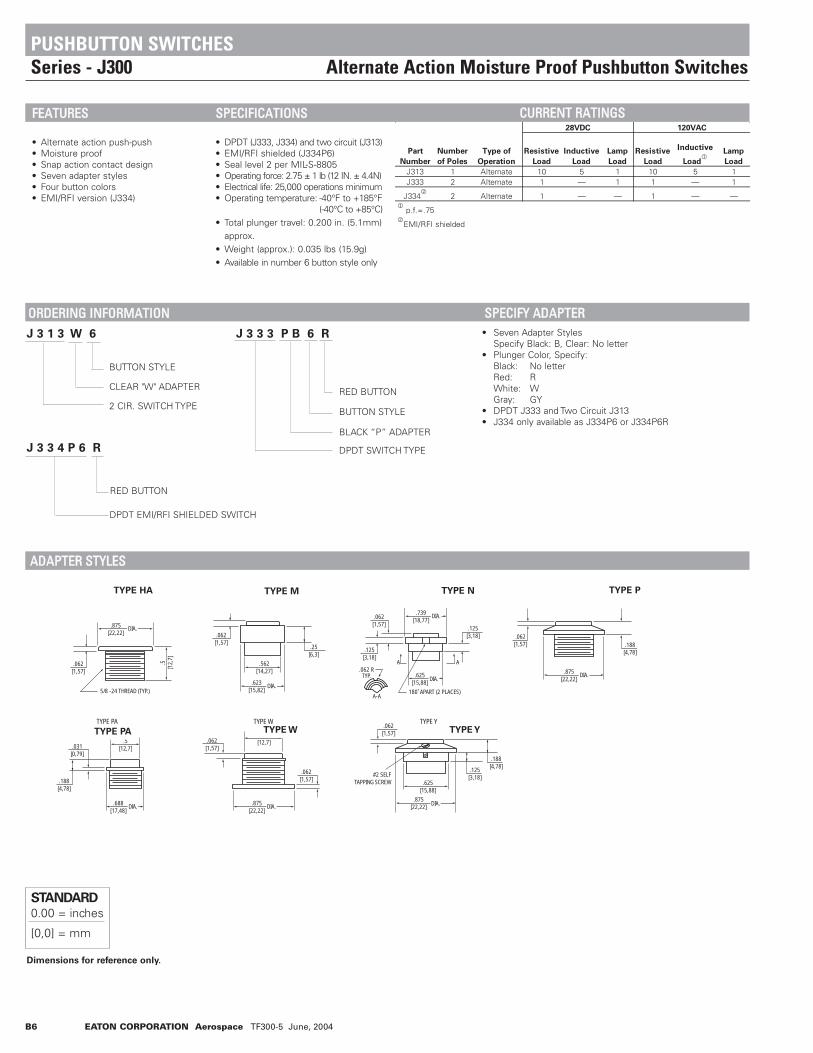
B6 EATON CORPORATION Aerospace TF300-5 June, 2004
Part
Number
Number
of Poles
Type of
Operation
Resistive
Load
Inductive
Load
Lamp
Load
Resistive
Load
Inductive
Load1
Lamp
Load
J313 1 Alternate 10 5 1 10 5 1J333 2 Alternate 1 — 1 1 — 1
J3342
2 Alternate 1 — — 1 — —1
p.f.=.752
EMI/RFI shielded
28VDC 120VAC
• Seven Adapter StylesSpecify Black: B, Clear: No letter
• Plunger Color, Specify:Black: No letterRed: RWhite: WGray: GY
• DPDT J333 and Two Circuit J313• J334 only available as J334P6 or J334P6R
DPDT EMI/RFI SHIELDED SWITCH
RED BUTTON
J 3 3 3 P B 6 R J 3 1 3 W 6
J 3 3 4 P 6 R
BUTTON STYLE
BUTTON STYLE
CLEAR "W" ADAPTER
2 CIR. SWITCH TYPE
BLACK “P” ADAPTER
DPDT SWITCH TYPE
RED BUTTON
Dimensions for reference only.
STANDARD0.00 = inches
[0,0] = mm
.688[17,48]
.188[4,78]
.031[0,79]
.5[12,7]
TYPE PA
DIA. .875[22,22]
.062[1,57]
.062[1,57]
.5[12,7]
.062[1,57]
.562[14,27]
.623[15,82]
.25[6,3]
.125[3,18]
.062 RTYP.
A-A180˚ APART (2 PLACES)
.062[1,57]
.739[18,77]
.125[3,18]
.625[15,88]
AA
.062[1,57]
.188[4,78]
.125[3,18]
.625[15,88]
.875[22,22]
#2 SELFTAPPING SCREW
TYPE W TYPE Y
DIA. DIA.
.062[1,57]
5/8 -24 THREAD (TYP.)
.5[1
2,7]
.875[22,22]
DIA.
DIA.DIA.
DIA.
.875[22,22]
.062[1,57] .188
[4,78]
DIA.
TYPE HA TYPE M TYPE N TYPE P
TYPE PA TYPE W TYPE Y
PUSHBUTTON SWITCHESSeries - J300 Alternate Action Moisture Proof Pushbutton Switches
FFEEAATTUURREESS
• Alternate action push-push• Moisture proof• Snap action contact design• Seven adapter styles• Four button colors• EMI/RFI version (J334)
SSPPEECCIIFFIICCAATTIIOONNSS
• DPDT (J333, J334) and two circuit (J313)• EMI/RFI shielded (J334P6)• Seal level 2 per MIL-S-8805• Operating force: 2.75 ± 1 lb (12 IN. ± 4.4N)• Electrical life: 25,000 operations minimum• Operating temperature: -40°F to +185°F
(-40°C to +85°C)• Total plunger travel: 0.200 in. (5.1mm)
approx.• Weight (approx.): 0.035 lbs (15.9g)• Available in number 6 button style only
CCUURRRREENNTT RRAATTIINNGGSS
OORRDDEERRIINNGG IINNFFOORRMMAATTIIOONN SSPPEECCIIFFYY AADDAAPPTTEERR
AADDAAPPTTEERR SSTTYYLLEESS

EATON CORPORATION Aerospace TF300-5 June, 2004 B7
Mounting dimensions for reference only.
STANDARD0.00 = inches
[0,0] = mm
C-H P/N NO. ON PANEL KEY
J334P6 1
J334P6 4
.010
10
20
30
40
50
60
70
80
.1 1.0 10 100 110
3 1 2 4
.468[11,90]
.468[11,90]
.75[19,05]
TYP.
3
4
1
2
S.P.D.T. - NC
TWO CIRCUIT
3
4
1
2
5 6
3
5
4
6
1
2
.16
[4,0
6]
.47[11,90]
DIA.
.19[4,83]
.75[19,05]
TYP.
2 P.D.T.
1.687[42,85]
1.453[36,91]
.437[11,10]
LOCKWASHER
5/8 - 24NEF-2B NUT
.50[12,7]
.375
[9,5
0]
.875
[22,
23]
J300
TWO CIRCUIT
RE
LATI
VE
SH
IELD
ING
EFF
ICIE
NC
Y -
DB
FREQUENCY - MHz
Graphic illustration defines relative shielding efficiency of RFI shielded component/ components over unshielded device.
PUSHBUTTON SWITCHESSeries - J300 Alternate Action Moisture Proof Pushbutton Switches
DDIIMMEENNSSIIOONNSS -- JJ330000
SSCCHHEEMMAATTIICC DDIIAAGGRRAAMMSS JJ331133 TTYYPPEE JJ333333 AANNDD JJ333344 TTYYPPEE
""WW"" JJ333344PP66 -- EEMMII//RRFFII SSHHIIEELLDDIINNGG
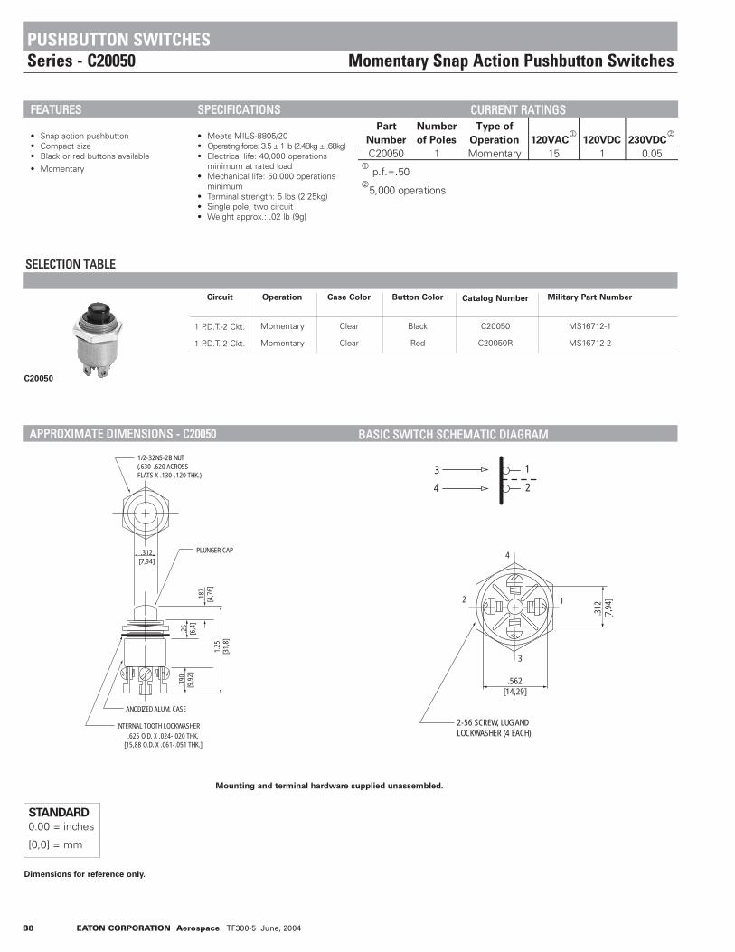
B8 EATON CORPORATION Aerospace TF300-5 June, 2004
Circuit Operation Case Color Button Color Catalog Number Military Part Number
C20050
1 P.D.T.-2 Ckt.
1 P.D.T.-2 Ckt.
Momentary
Momentary
Clear
Clear
Black
Red
C20050
C20050R
MS16712-1
MS16712-2
Part
Number
Number
of Poles
Type of
Operation 120VAC1
120VDC 230VDC2
C20050 1 Momentary 15 1 0.051
p.f.=.502
5,000 operations
SSEELLEECCTTIIOONN TTAABBLLEE
Dimensions for reference only.
STANDARD0.00 = inches
[0,0] = mm
.312[7,94]
ANODIZED ALUM. CASE
PLUNGER CAP
.625 O.D. X .024-.020 THK.[15,88 O.D. X .061-.051 THK.]
INTERNAL TOOTH LOCKWASHER
1/2-32NS-2B NUT(.630-.620 ACROSSFLATS X .130-.120 THK.)
1.25
[31,
8]
.25
[6,4
].1
87[4
,76]
.390
[9,9
2]
.562[14,29]
2-56 SCREW, LUG ANDLOCKWASHER (4 EACH)
4
2 1
3
.312
[7,9
4]
3
4
1
2
PUSHBUTTON SWITCHESSeries - C20050 Momentary Snap Action Pushbutton Switches
FFEEAATTUURREESS
• Snap action pushbutton• Compact size• Black or red buttons available
• Momentary
SSPPEECCIIFFIICCAATTIIOONNSS
• Meets MIL-S-8805/20• Operating force: 3.5 ± 1 lb (2.48kg ± .68kg)• Electrical life: 40,000 operations
minimum at rated load• Mechanical life: 50,000 operations
minimum• Terminal strength: 5 lbs (2.25kg)• Single pole, two circuit• Weight approx.: .02 lb (9g)
CCUURRRREENNTT RRAATTIINNGGSS
AAPPPPRROOXXIIMMAATTEE DDIIMMEENNSSIIOONNSS -- CC2200005500 BBAASSIICC SSWWIITTCCHH SSCCHHEEMMAATTIICC DDIIAAGGRRAAMM
Mounting and terminal hardware supplied unassembled.

EATON CORPORATION Aerospace TF300-5 June, 2004 B9
Base
Catalog
Number Circuit Color
Case Color Case Color
Code Suffix Color Code Suffix
J4004 Series
J4004 1 P.D.T.-2 Ckt.
Black
Clear
B
None
Gray
White
Red
Black
GY
W
R
None
SSEELLEECCTTIIOONN TTAABBLLEE
Dimensions for reference only.
STANDARD0.00 = inches
[0,0] = mm
• Catalog number of base switch - followed by suffix letters for color of case and pushbutton
Order ExampleJ4004 B R = J4004BR
BaseCatalogNumber
CaseColor
PushbuttonColor
CompleteNumber
1.46
9[3
7,31
]
5/8 - 24NEF NUT
.375[9,50]
.875[22,23]
.468[11,91]
DIA. HOLE (4).055[1,40]
.265[6,75]
.265[6,75]
.156[3,97]
.093[2,38]
.375[9,53]
.875[22,23]
.468[11,90]
.468[11,90]
.750[19,05]
.062[1,59]
5/8 - 24 NEF - 2B NUT
PUSHBUTTON SWITCHESSeries - J4004 Alternate Action Alternate Action Pushbutton Switches
Part
Number
Number
of Poles
Type of
Operation
Resistive
Load
Inductive
Load
Resistive
Load
Inductive
Load1
J4004 1 Alternate 10 5 10 51
p.f.=.75
28VDC 125VAC
WWHHEENN OORRDDEERRIINNGG SSPPEECCIIFFYY……
SSEERRIIEESS AANNDD TTYYPPEE
AAPPPPRROOXXIIMMAATTEE DDIIMMEENNSSIIOONNSS
SSCCHHEEMMAATTIICC DDIIAAGGRRAAMM
FFEEAATTUURREESS
• Alternate action• Snap action mechanism• Single piece case construction• Two case and four button colors available
SSPPEECCIIFFIICCAATTIIOONNSS
• Single pole, double throw, two circuit• Operating force: 2 ± 0.75 lb (8.8N ± 3.3N)• Mechanical life: 50,000 operations
minimum• Total plunger travel: 0.172in. (4.37mm)
approx.• Weight (approx.): 0.32 lbs (15g)• Solder lug terminals
CCUURRRREENNTT RRAATTIINNGGSS
.25[6,35]
.468[11,90]
.75[19,05]
TYP.
3
4
1
2
31
2 4
.469[11,91]

B10 EATON CORPORATION Aerospace TF300-5 March 2004
Series
and Type Circuit
Catalog
Number
J100
J103
1 P.S.T.-NO.
1 P.D.T.-ON-ON
J100
J103
SSEELLEECCTTIIOONN TTAABBLLEE
Dimensions for reference only. Mounting and terminal hardware supplied unassembled.
STANDARD0.00 = inches
[0,0] = mm
.750[19,05]
7/8 - 27 NS-2 NUT
#6-32 SCREW#6 LOCKWASHER
• J103 has three terminals
3
2
1
J103
PUSHBUTTON SWITCHESSeries - J100 Alternate Action High Current Pushbutton Switches
FFEEAATTUURREESS
• Alternate action• Snap action mechanism• Single piece case construction• Compact cylindrical size• Black button standard• Other colors available
SSPPEECCIIFFIICCAATTIIOONNSS
• Rated up to 40 amps DC or AC• Operating force: 4 ± 2 lbs (1.8kg ± 0.9kg)• Total plunger travel:
0.25 in.(0.635mm) approx.• Weight (approx.):
1 oz. approx. (28.3g)
CCUURRRREENNTT RRAATTIINNGGSSPart
Number
Number
of Poles
Type of
Operation Continuous Resistive Inductive Lamp Continuous Resistive Inductive Lamp
J100 1 Alternate 40 20 15 5 40 10 10 3J103 1 Alternate 40 20 15 5 40 10 10 3
28VDC 115VAC
AAPPPPRROOXXIIMMAATTEE DDIIMMEENNSSIIOONNSS -- JJ110000 AANNDD JJ110033
SSCCHHEEMMAATTIICC DDIIAAGGRRAAMMSS
J100
Rear Terminal ViewJ100 J103
J100
.4375[11,11]
7/8 INTERNAL SHAKEPROOFLOCKWASHER
.125[3,18].437
[11,11]
.062[1,59]
.109[2,78]
.328[8,33]
MAX.2.53264,31
.750[19,05]
27 NS-28 NUT
1
1[25,4]
3
2
#6-32 NC 2A SCREW& LOCKWASHER

Part
Number
Number
of Poles
Type of
Operation Resistive Inductive Lamp Resistive Inductive
W300 1 Momentary 10 5 3 151
.75 PF
28VDC 125VAC1
EATON CORPORATION Aerospace TF300-5 June, 2004 B11
Series
and Type OperationCircuit
Catalog Schematic
W300
W300 Momentary
Snap Action
1 P.S.T.-NO
1 P.S.T.-NC
1 P.-2 Circuit
W301
W302
W303
SSEELLEECCTTIIOONN TTAABBLLEE
Dimensions for reference only. Mounting and terminal hardware supplied unassembled.
R G G R
W 3 0 1 R •Plunger Color:Gray: GYWhite: WRed: RBlack: No Letter
PLUNGER CAP COLOR
BASIC SWITCH NO.
SUPPLIED WITH TWO TERMINAL SCREWS, LOCK WASHERS AND LUGS.
W300 SERIES W/SOLDER TERMINALS W300 SERIES W/SOLDER LUG TERMINALS
SUPPLIED WITH FOUR TERMINAL SCREWS, LOCK WASHERS AND LUGS.
.562[14,29]
.312[7,94]
.203[5,16]
1.343[34,13]
.250[6,35]
.187[4,76]
.500[12,70
INTERNAL TOOTH LOCKWASHER]
PLASTIC PLUNGER CAPZEROK SEAM
.406[10,32]
.625[15,88]
1/2 - 32, NS - 2B NUT
.562[14,29]
.312[7,94]
1.531[38,89]
.250[6,35]
.187[4,76]
.500[12,70
INTERNAL TOOTH LOCKWASHER]
PLASTIC PLUNGER CAPZEROK SEAM
.406[10,32]
.625[15,88]
1/2 - 32, NS - 2B NUT
R
GG
R
.390[9,92]
STANDARD0.00 = inches
[0,0] = mm
W301, W302 W303
PUSHBUTTON SWITCHESSeries - W300 Moisture-proof Pushbutton Switches
FFEEAATTUURREESS
• Moisture-proof• Momentary snap action• Black plunger (as standard)• Various color adapters available
SSPPEECCIIFFIICCAATTIIOONNSS
• Electrical life: 25,000 operations minimum at rated current
• Temperature range:-67°F to +185°F (-55°C to +85C°)
• Exceeds MIL-S-8805 Seal Level 2• Operating force: 5 ± 1 lb
(22N ± 4.4N)• Total plunger travel:
0.085 in. (0.22mm) approx.• Weight with adapter: 0.025 lbs approx.
CCUURRRREENNTT RRAATTIINNGGSS
WWHHEENN OORRDDEERRIINNGG SSPPEECCIIFFYY……
AAPPPPRROOXXIIMMAATTEE DDIIMMEENNSSIIOONNSS -- WW330000
Catalog
Number

B12 EATON CORPORATION Aerospace TF300-5 June, 2004
W9000
SSEELLEECCTTIIOONN TTAABBLLEE
Dimensions for reference only. Mounting and terminal hardware supplied unassembled.
3For W9006 or SPDT circuit, mount terminal jumper to terminals #2 and #4.
BUTTON COLOR
W 9 0 0 1 C B
BASE SWITCH
ADAPTER COLOR.375
[9,5
0]
1.50
6 ±
.031
[48,
42]
[0,7
9]
1.125[28,58]
.688[17,46]
.156
[3,9
7].1
56[3
,97]
.594
[15,
08]
.203
[5,1
6]
.391
[9,9
2
1 2 1 21 2 3 4 1 23 41 21 2
TERM JUMPERCENTER TERM. 3CENTER TERM. 3
2
1
2
11
2
3 4
1
2
3 4
2
1
3
2
1
3
W9001W9001 W9002W9002 W9003W9003 W9004W9004 W9005W9005 W9006W9006
Normally OpenNormally Open Normally ClosedNormally Closed Two CircuitTwo Circuit 3 Terminal N.O.3 Terminal N.O. 3 Terminal N.C.3 Terminal N.C. S.P.D.T.S.P.D.T.STANDARD0.00 = inches
[0,0] = mm
PUSHBUTTON SWITCHESSeries - W9000 Swivel Action Pushbutton Switches
Part
Number
Number
of Poles
Type of
Operation Resistive Inductive Lamp Resistive Inductive1
W9000 1 Momentary 10 5 3 151
p.f.=.752
3 amps max. through center terminal.
28VDC2
120VAC
SSEERRIIEESS AANNDD TTYYPPEE
Operation Color Code Suffix Color Code Suffix
W9001 1 P.S.T.-N.O.W9002 1 P.S.T.-N.C.W9003 1 P.-2 Circuit Black None Red RW9004 Momentary Snap Action 1 P.S.T. Clear C Black B
3 Terminal N.O. Gray NoneW9005 1 P.S.T.
3 Terminal N.C.W9006 1 P.D.T.-N.O.-N.C.
Pushbutton Color
Code Suffixes - Add to Cat. No.
Circuit
and Schematic
Base
Catalog
Number
Adapter Color
DDIIMMEENNSSIIOONNSS -- WW99000000 PPAANNEELL CCUUTTOOUUTT WWHHEENN OORRDDEERRIINNGG SSPPEECCIIFFYY……
BBAASSIICC SSWWIITTCCHH && SSCCHHEEMMAATTIICC DDIIAAGGRRAAMM
FFEEAATTUURREESS
• Swivel action allows operation from any angle
• Large button• Splash proof• Momentary snap action• Solder lug terminals• Variety of adapter and button colors
SSPPEECCIIFFIICCAATTIIOONNSS
• Meets MIL-S-8805 seal level 6 (splash proof)
• Electrical life: 25,000 operations minimum at rated load
• Mechanical life: 200,000 operations (50,000 operations for 3 terminal design)
• Operating force: 4 ± 1 lb (17.6N ± 4.4N)• Total plunger travel:
0.085 in. (0.22mm) approx.• Weight with adapter:
0.088 lbs approx.
CCUURRRREENNTT RRAATTIINNGGSS
.5[1
2,7]
.625[15,88]
.125 ± .003[3.18] [0.08]
3

EATON CORPORATION Aerospace TF300-5 June, 2004 B13
W9600
SSEELLEECCTTIIOONN TTAABBLLEE
Dimensions for reference only.
BUTTON COLOR
W 9 6 0 1 B R
BASIC SWITCH
ADAPTER COLOR
STANDARD0.00 = inches
[0,0] = mm
.390[9,92]
.281[7,14]
.203[5,16]
.750
[19,
05]
.281[7,14]
.875[22,23]
.062[1,59]1.
656
[42,
07]
5/8-24 NEF-2B NUT
NEOPRENEGASKET (2)
ANODIZEDALUMINUMADAPTER
ANODIZED ALUMINUM CASE
DIA..562[14,29]
Base
Catalog
Number OperationCircuit
and Schematic Color
Adapter Color Pushbutton Color
Code Suffixes - Add to Cat. No.
Code Suffix Code Suffix Code Suffix
W9001
W9002
W9003
W9004
W9005
W9006
Momentary Snap
Action
1 P.S.T.-N.O.
1 P.S.T.-N.C.
1 P.-2 Circuit
1 P.S.T.
3 Terminal N.O.
1 P.S.T.
3 Terminal N.C.
1 P.D.T.-N.O.-N.C.
Black
Clear
None
C
Red
Black
Gray
R
B
None
PUSHBUTTON SWITCHESSeries - W9600 Wide Button Moisture-Proof Pushbutton Switches
Part
Number
Number
of Poles
Type of
Operation Resistive Inductive Lamp Resistive Inductive1
W9600 Series 1 Momentary 10 5 3 15W9623 Series 2 Circuit Momentary 10 5 3 — —
1 p.f.=.752
3 amps max. through center terminal.
28VDC2
125VAC
DDIIMMEENNSSIIOONNSS -- WW99660000 PPAANNEELL CCUUTTOOUUTT WWHHEENN OORRDDEERRIINNGG SSPPEECCIIFFYY……
CCUURRRREENNTT RRAATTIINNGGSS
SSEERRIIEESS AANNDD TTYYPPEE
FFEEAATTUURREESS
• Splash-proof• Wide diameter button• Variety of button colors available• Momentary snap action• Solder lug terminals• RFI shielded version (W9623)
SSPPEECCIIFFIICCAATTIIOONNSS
• Meets MIL-S-8805 seal level 6 (splash-proof)
• Electrical life: 25,000 operations minimum at rated current
• Mechanical life: 200,000 operations (50,000 operations for 3 terminal design)
• Operating force: 4 ± 1 lbs (17.6N ± 4.4N)• Total plunger travel:
0.080 in. ± .015 (0.21mm ± .003) approx.• Vibration: 10-2000Hz 15g.• Shock: 100g. 6 Ms sawtooth• Weight with adapter:
0.048 lbs approx.• EMI/RFI shielded (W9623 only)
.64MAX

B14 EATON CORPORATION Aerospace TF300-5 June, 2004
1 2 1 21 2 3 4 1 23 41 21 2
3 3TERM JUMPER
2
1
2
1
1
2
3 4
1
2
3 42
1
3
2
1
3
W9601
W9623
Normally Open
Graphic illustration defines relative shielding efficiency of RFI shielded component/ components over unshielded device.
Normally Closed Two Circuit 3 Terminal N.O. S.P.D.T.3 Terminal N.C.
W9602 W9603 W9604
Center Term 3W9605
Center Term 3
W96061
11 For W9606 or SPDT circuit, mount terminal jumper to terminal #2 and #4.
SCHEMATIC.75[19,05]
1.859[47,22]
1.453[36,91]
.75[19,05]
.281[7,14]
NEOPREN GASKET
LOCKWASHER
5/8-24 NEF-2B NUT
.875
[22,
23]
4 3
2
11 2
3 4
C-H P/N NO. ON PANEL KEY
W9623 1
W9623 4
.010
10
20
30
40
50
60
70
80
.1 1.0 10
FREQUENCY - MHz
100 110
RELA
TIVE
SHI
ELDI
NG E
FFIC
IENC
Y -
DB
Dimensions for reference only.
PUSHBUTTON SWITCHESSeries - W9600 Wide Button Moisture-Proof Pushbutton Switches
BBAASSIICC SSWWIITTCCHH && SSCCHHEEMMAATTIICC DDIIAAGGRRAAMM
TTWWOO CCIIRRCCUUIITT MMOODDEELL WW99662233 EEMMII//RRMMII SSHHIIEELLDDEEDD
STANDARD0.00 = inches
[0,0] = mm

EATON CORPORATION Aerospace TF300-5 June, 2004 B15
Dimensions for reference only.
STANDARD0.00 = inches
[0,0] = mm
BUTTON COLOR
• Catalog number of base switch - followed by suffix numbers of options (when required) as selected from Selection Table.
Order Example:C100 HA 6 C100HA6C100 None 7R C1007R
ADAPTER COLOR
ADAPTER TYPE
BASE SWITCH AND CIRCUIT
BaseSwitchCatalogNumber
Mtg.Adapter
andColor
ButtonStyleand
Color
CompleteNumber
BUTTON STYLE
C100
WC150
W100
SSEELLEECCTTIIOONN TTAABBLLEE
W 1 0 1 P B 6 R
PUSHBUTTON SWITCHESSeries - C100, W100, WC150 Uniform Panel Appearance Switches
Part Number Resistive Load
Inductive
Load Lamp
Resistive
Load
Inductive
Load3
C100 Series 101
5 3 101
5
W100 Series 102
5 3 102
5WC1500 Series — 2 — — —
W403 P6 (R)4
10 5 — — —1
3 amps max. through center terminal of A800 and A112002
3 amps max. through center terminal of W104 and W1053
p.f. = .754
EMI/RFI shielded
28VDC 125VAC
Circuit Color Style Color
SP-NO C100 C111 — — 2, 6, or 7SP-NC C3100 C112 — — On Switch
1 P.D.T.-2 Ckt. C200 C113 — — withoutSP-NO 3 Term. A800 C114 — — AdapterSP-NC 3 Term. A11200 C115 — — 1 P.D.T. Dbl Brk C4100 C116 — — 2, 3, 4 or 7
On Switcheswith Adapter
Standard: No Alpha=SP-NO — — W101 W111 N, P, PA, 2, 3, 4, 6 or 7 BlackSP-NC — — W102 W112 W, L B=Black R=Red
1 P.D.T.-2 Ckt. — — W103 W113 (with #5 R=Red W=WhiteSP-NO 3 Term. — — W104 W114 button only) No Alpha=SP-NC 3 Term. — — W105 W115 Optional: Clear1 P.D.T. Dbl Brk — — W106 W116 D, E, HA, 1 P.D.T.-2 Ckt. — — — — J, M, PL, 6
U, Y
2 P.D.T. 4 Ckt. — — WC150 — 2, 3, 4, 6 or 7May be Jumpered
for 2 P.D.T.
6
Options - Suffix Number
Solder Lug Terminals
Base Switch - Catalog Number
Mounting Adapters
Light Op. Force
(2 +/- .5 lb.)
Sealed
Auxiliary Buttons
Normal
Force
Normal
Force Type
Non-Sealed
Light Op. Force
(2 +/- 1 lb.)
SSEERRIIEESS AANNDD TTYYPPEE
WWHHEENN OORRDDEERRIINNGG SSPPEECCIIFFYY……
FFEEAATTUURREESS
• Low level switching capability• Moisture-proof• Momentary action (except #7 button)• Push-Pull action (#7 button only)• Up to 1 million mechanical cycles• EMI/RFI shielding available• Tease resistant, snap action• Six circuit arrangements available• Various adapter, button styles and
colors• High contact pressure • Compact size• Corrosion resistant case and adapters
SSPPEECCIIFFIICCAATTIIOONNSS
• MS27903 (WC150 series only)• Operating temperature: -40°F to +158°F
(-40°C to +70°C)• Electrical life: 25,000 cycles at
rated load• Operating force:
Approx. 2.5-5 lbs (Momentary)Approx. 1.5-2.5 lbs (Push-Pull)
• Total plunger travel: 0.085 in. (2.16mm) approx.
• W100 and WC150 exceeds seal level 2per MIL-S-8805
• C100 series meets seal level 2 per MIL-S-8805
CCUURRRREENNTT RRAATTIINNGGSS

B16 EATON CORPORATION Aerospace TF300-5 June, 2004
.94
[23,
8]
.87
[22,
2].6
3[1
5,9]
.63
[15,
9]
.63[15,9]
58-24 NEF-2B NUT
C100 Without AdapterC100 Without Adapter
W100W100
WC150WC150(RF1 Versions Slightly Larger)(RF1 Versions Slightly Larger)
C100 With AdapterC100 With Adapter
CASE DIA.
.57[13,3]
1/2-32 UNS - 28 NUT
CASE DIA.
3 4 5 6
Series C100
Without AdapterWith Adapter
Series W100 & WC150
With AdapterWithout Adapter
Style Number 2
A
mm. in.
7.9 .319.5 .37
9.5 .37.37
7.9 .317.9 .31
7.9 .31.34
- -9.5 .37
9.5 .37.37
- -7.9 .31
7.9 .31.34
- -9.5 .37
9.5 .37.37
- -4.8 .19
4.8 .19.22
7.9 .31- -
9.5 .37.37
4.8 .19- -
6.4 .25.38
7.9 .317.9 .31
9.5 .37.37
11.9 .475.6 .22
9.5 .38.41
Series Number mm. in.
A
mm. in. mm. in. mm. in. mm. in. mm. in. mm. in. mm. in.mm. in.
A A A BB B B B
Style Number 3 Style Number 4 Style Number 6 Style Number 7
B
A
Style Number 2 Style Number 3 Style Number 4 Style Number 6 Style Number 7
1
2
1
2
SINGLE POLENORMALLY OPEN
SINGLE POLENORMALLY CLOSED
SINGLE POLEDOUBLE THROW
2 CIRCUITS
SINGLE POLENORMALLY OPEN
3 TERMINALS
SINGLE POLENORMALLY CLOSED
3 TERMINALS
SINGLE POLEDOUBLE THROW
(TERMINAL JUMPER SUPP;IED UNINSTALLED)
3 41 2 1 2 3
3
4 1 2 3 4
TERM. JUMPER
1 2
3
2
1
3 4
1
1
2
3
2
3 4
1
21
2
3
Dimensions for reference only.
STANDARD0.00 = inches
[0,0] = mm
PUSHBUTTON SWITCHESSeries - C100, W100, WC150 Uniform Panel Appearance Switches
AAPPPPRROOXXIIMMAATTEE DDIIMMEENNSSIIOONNSS -- PPUUSSHHBBUUTTTTOONN SSWWIITTCCHHEESS
AAPPPPRROOXXIIMMAATTEE DDIIMMEENNSSIIOONNSS -- AAUUXXIILLIIAARRYY BBUUTTTTOONNSS
SSCCHHEEMMAATTIICC DDIIAAGGRRAAMMSS
Style Number 2
B
A
Style Number 3 Style Number 4 Style Number 6 Style Number 7Style Number 2 Style Number 3 Style Number 4
B
A
Style Number 6 Style Number 7Style Number 2 Style Number 3 Style Number 4
B
A
Style Number 6 Style Number 7Style Number 2 Style Number 3 Style Number 4 Style Number 6
B
A
Style Number 7
SINGLE POLE NORMALLY OPEN
SINGLE POLE NORMALLY CLOSED
SINGLE POLE DOUBLE THROW
2 CIRCUITS
SINGLE POLE NORMALLY OPEN
3 TERMINALS
SINGLE POLE NORMALLY CLOSED
3 TERMINALS
SINGLE POLE DOUBLE THROW
(TERMINAL JUMPER SUPPLIED UNINSTALLED)

EATON CORPORATION Aerospace TF300-5 June, 2004 B17
Graphic Illustration defines relative shielding efficiency of RFIshielded component/ components over unshielded device.
Graphic Illustration defines relative shielding efficiency of RFIshielded component/ components over unshielded device.
Dimensions for reference only.
STANDARD0.00 = inches
[0,0] = mm
1.875[47,63]
1.719[43,66]
.437[11,10]
LOCKWASHER
3/4 - 32NS-2B NUT
.50[12,7]
.375
[9,5
0]
1.06
2[2
6,98
]
1.00[25,4]
4 5
1 8
63
72
1.75[23,65]
1.359[34,52]
.437[11,10]
LOCKWASHER
5/8 - 24NEF-2B NUT
.50[12,7]
.375
[9,5
0]
.875
[22,
23]
.75[19,05]
3
1
4
2
SCHEMATIC
4 CIRCUIT
1 2 7 8 4 3 6 5
SCHEMATIC
1 2
3 4
2 CIRCUIT
P/N NO. ON PANEL KEY
W1501 1
.010
10
20
30
40
50
60
70
80
.1 1.0 10
FREQUENCY - MHz
100 110
RELA
TIVE
SHI
ELDI
NG E
FFIC
IENC
Y -
DB
P/N NO. ON PANEL KEY
W403P6 1
10
20
30
40
50
60
70
80
RELA
TIVE
SHI
ELDI
NG E
FFIC
IENC
Y -
DB
PUSHBUTTON SWITCHESSeries - C100, W100, WC150 Uniform Panel Appearance Switches
AAPPPPRROOXXIIMMAATTEE DDIIMMEENNSSIIOONNSS -- MMOOUUNNTTIINNGG AADDAAPPTTEERRSS
J300BUSHINGSTYLE.AI
TYPE N
.125[3,18]
.063 RTYP.
A-A 180˚ APART (2 PLACES)
.063[1,6]
.739[18,77]
.125[3,18]
.625[15,88]
AA
DIA
DIA
.875[22,22]
.063[1,6]
.063[1,6]
.5[12,7]
TYPE W
5/8 (.625) - 24UNEF - 2A
+.000-.016
TYPE P
.875[22,22]
.063[1,6] .188
[4,78]
5/8 (.625) - 24UNEF - 2A
+.000-.018 .688
[17,48]
.188[4,76]
.031[0,79]
.5[12,7]
TYPE PA
+.000-.018
5/8 (.625) - 24UNEF - 2A
1.250[31,75]
.563
[14,3
0]
.625[15,88]
TYPE L WITH 5 PLUNGER CAP
1/2 INT. LOCKWASHER1/2-32UNS - 2B NUT
.438[11,13]
.062[1,57]
.750[19,05]
+.000-.016
.563
[14,
39]
.187[4,75]
5/8 (.625) - 24UNEF - 2A
TYPE D TYPE E
.875[22,22]
.062[1,57] .188
[4,78]
+.000-.016
.625
[15,
88]
5/8 (.625) - 24UNEF - 2A
.062[1,57]
.5[1
2,7]
.875 [22,22]
+.000-.016
5/8 (.625) - 24UNEF - 2A
TYPE HA.875
[22,22]+.000-.016
TYPE J
.062[1,57]
5/8 (.625) - 24UNEF - 2A
.875 [22,22]
+.000-.010
.500
[12,
7]
TYPE M
.063[1,6]
.563[14,39]
.623[15,82]
.25[6,3]
+.000-.016
.500
[12,
7]
TYPE PL
.875[22,22]
.062[1,57] .188
[4,78]
.500
[12,
7]
5/8 (.625) - 24UNEF - 2A
RECESS FOR O-RING(SUPPLIED)
+.000-.016
.063[1,6]
TYPE U
.750[19,05]
+.000-.016
.063[1,6]
.500
[12,
7]
5/8 (.625) - 24UNEF - 2A
.063[1,6]
.188[4,78]
.625[15,88]
.875[22,22]
+.000-.016
#2 FLAT HEAD SELFTAPPING SCREW
TYPE Y
OOPPTTIIOONNAALL::
SSTTAANNDDAARRDD::
EEMMII//RRFFII SSHHIIEELLDDEEDD
WW11550011
WW440033PP66
PLUNGER CAP COLORS:CHROME: NO LETTERRED: RBLACK: BTOTAL PLGR TRAVEL: .438 APPROX.OVERTRAVEL: .313 APPROX.
NNOOTTEE:: IINNTTEERRNNAALL TTHHRREEAADDSS 11//22 -- 3322 UUNNSS--22BB

B18 EATON CORPORATION Aerospace TF300-5 June, 2004
.250.250[6,35][6,35]
.406.406
PANEL MTG HOLE DIMENSIONSPANEL MTG HOLE DIMENSIONS
B9001, BW9001B9001, BW9001B9021, BW9021B9021, BW9021
S.P.S.T - NOS.P.S.T - NO
B9021, BW9021, B9022, BW9022B9021, BW9021, B9022, BW9022PANEL MTG HOLE DIMENSIONSPANEL MTG HOLE DIMENSIONS
.180.180
B9002, BW9002B9002, BW9002B9022, BW9022B9022, BW9022
S.P.S.T - NCS.P.S.T - NC
PUSHBUTTON SWITCHESSub-Miniature Pushbutton Switches
Part
Number
Number
of Poles
Type of
Operation
Resistive
Load
Inductive
Load
Resistive
Load
Inductive
Load1
B9001 1 Momentary 7 4 7 4B9002 1 Momentary 7 4 7 4BW9001 1 Momentary 7 4 7 4BW9002 1 Momentary 7 4 7 4B9021 1 Momentary 7 4 7 4B9022 1 Momentary 7 4 7 4BW9021 1 Momentary 7 4 7 4BW9022 1 Momentary 7 4 7 4B7070 2 Momentary 1 1 1 1
BR70702
2 Momentary 1 1 1 11
p.f.=.752
EMI/RFI shielded
28VDC 125VAC
SSEERRIIEESS TTYYPPEE
B9001, 2
Single Pole
Catalog
Number
Military
Part Numbers
M8805/96
Button
Color Circuit
Case
Color
Enclosure
Design
B9001R -001 Red SPST-NO Clear (unsealed)B9001B -002 Black SPST-NO Clear (unsealed)B9002R -003 Red SPST-NC Clear (unsealed)B9002B -004 Black SPST-NC Clear (unsealed)B9001BR -005 Red SPST-NO Black (unsealed)B9001BB -006 Black SPST-NO Black (unsealed)B9002BR -007 Red SPST-NC Black (unsealed)B9002BB -008 Black SPST-NC Black (unsealed)BW9001R -009 Red SPST-NO Clear (dust tight)BW9001B -010 Black SPST-NO Clear (dust tight)BW9002R -011 Red SPST-NC Clear (dust tight)BW9002B -012 Black SPST-NC Clear (dust tight)BW9001BR -013 Red SPST-NO Black (dust tight)BW9001BB -014 Black SPST-NO Black (dust tight)B9002BR -015 Red SPST-NC Black (dust tight)B9002BB -016 Black SPST-NC Black (dust tight)
B9021, 22
Single Pole
Standard Dust Tight Circuit
B9021CB BW9021CB SP-NO Clear BlackB9021CR BW9021CR Clear RedB9021BB BW9021BB Black BlackB9021BR BW9021BR Black RedB9022CB BW9022CB SP-NC Clear BlackB9022CR BW9022CR Clear RedB9022BB BW9022BB Black BlackB9022BR BW9022BR Black Red
Catalog Number Case
Color
Button
Color
SSCCHHEEMMAATTIICC DDIIAAGGRRAAMMSS -- BB AANNDD BBWW SSEERRIIEESS PPAANNEELL CCUUTT--OOUUTT PPAANNEELL CCUUTT--OOUUTT
SSPPEECCIIFFIICCAATTIIOONNSS• MIL-S-8805 approved• Total plunger travel:
.08/0.093 in. (0.236 mm) minimum• Electrical life: 25,000 operations
minimum at de-rated current 10,000 operations minimum at rated current
• Operating force:B9000 1.5 (6.66N) ± .5 lb (2.22N)BW9000, B9020& BW9020 1.75 (7.77N) ± .5 lb (2.22N)B7070 1.5 (6.66N) ± .75 lb (3.33N)BR7070 2.0 (8.88N) ± .75 lb (3.33N)
• Weight approx.:B9000 0.01 lb (4.5g) Max.& B9020BW9000 0.01 lb (4.5g) Max.& BW9020B7070 0.02 lb (9.1g) Approx.BR7070 0.02 lb (9.1g) Max.
• EMI/RFI shielded (BR7070 only)
CCUURRRREENNTT RRAATTIINNGGSSFFEEAATTUURREESS
• Sealed or unsealed versions• Low operating force• Momentary snap action• EMI/RFI version (BR7070)• Black or red adapter colors available• Clear or black case colors available• Compact, space saving design
SSEELLEECCTTIIOONN TTAABBLLEESSAAPPPPRROOXXIIMMAATTEE DDIIMMEENNSSIIOONNSS
.34[8,7]
.06[1,4]
.13[3,3]
1.05
[26,
6]
.28
[7,2
]
.13[3,2]
DIA.
PLASTIC PUSHBUTTON.
1/4-40NS-2A BUSHING[6,35]
DIA HOLE (2)
INTERNAL TOOTHLOCKWASHER
.16[4,0]
DIA.
MAX
.
Solder Terminals
.34[8,7]
.55[13,9]
.06[1,4]
.13[3,3]
1.05
[26,
6].3
1[7
,9]
.13[3,2]
.09[2,4]
DIA.
PLASTIC PUSHBUTTON.
13/32 - 32NS-2A BUSHING[10,32] DIA.
DIA
INTERNAL TOOTHLOCKWASHER
.16[4,0]
DIA.
MAX
.
Solder Terminals

EATON CORPORATION Aerospace TF300-5 June, 2004 B19
B7070
Two Pole
*EMI/RFI shielded
.250[6,35]
PANEL MTG HOLE DIMENSIONS
D.P.D.T.D.P.D.T.
1
3
2
46
5
.12[3,0]
.055[1,40] DIA. HOLES (6)
CASE
INTERNALTOOTHLOCKWASHER
PLUNGER CAP
1
5 6
3
2
4.4
7[1
1,9]
.31
[7,9
]
.16
[4,1
].1
4[3
,6]
.28
[7,1
]1.
30[3
3,0]
1/4 - 4ONS - 2A BUSHING[6,35] DIA.
Solder Terminals
.12[3,0]
.055[1,40]
DIA. HOLES (6)
ANODIZED ALUMINUM C ASE
INTERNALTOOTHLOCKWASHER
PLASTIC PLUNGER CAP
1
5 6
3
2
4
.47
[11,
9].3
1[7
,9]
.16
[4,1
].1
4[3
,6]
.28
[7,1
]1.
30[3
3,0]
1/4 - 4ONS - 2A BUSHING[6,35] DIA.
Dimensions for reference only.
STANDARD0.00 = inches
[0,0] = mm
PUSHBUTTON SWITCHESSub-Miniature Pushbutton Switches
Catalog
Number
Military Part
Number Case Color
Button
Color
B7070 M8805/95-001 Clear Black
B7070R M8805/95-002 Clear Red
B7070B M8805/95-003 Black Black
B7070BR M8805/95-004 Black Red
SSCCHHEEMMAATTIICC DDIIAAGGRRAAMMSS -- BB77007700 PPAANNEELL CCUUTT--OOUUTT
B7070
Two Pole
Catalog
Number
Case
Color
Button
Color
BR7070 Clear BlackBR7070R Clear RedBR7070B Black BlackBR7070BR Black Red
SSCCHHEEMMAATTIICC DDIIAAGGRRAAMMSS -- BB77007700 PPAANNEELL CCUUTT--OOUUTT
AAPPPPRROOXXIIMMAATTEE DDIIMMEENNSSIIOONNSS SSEELLEECCTTIIOONN TTAABBLLEESSSSEERRIIEESS TTYYPPEE
Solder Terminals
.250.250[6,35][6,35]
PANEL MTG HOLE DIMENSIONSPANEL MTG HOLE DIMENSIONS
D.P.D.T.
1
3
2
46
5
.250[6,35]
PANEL MTG HOLE DIMENSIONS
D.P.D.T.D.P.D.T.
1
3
2
46
5
.250.250[6,35][6,35]
PANEL MTG HOLE DIMENSIONSPANEL MTG HOLE DIMENSIONS
D.P.D.T.
1
3
2
46
5

B20 EATON CORPORATION Aerospace TF300-5 June, 2004
Dimensions for reference only.
STANDARD0.00 = inches
[0,0] = mm
A20000*
J20000
*NOTE: Catalog number does not include lens shown above.
.468[11,89]
.375[9,53]
.125[3,18]
DIA
.468[11,89]
.447
[11,
35]
D.P.D.T.D.P.D.T.
1
8
3
2
46
5
7
2 CIRCUIT2 CIRCUIT
1
8
43
2
7
PUSHBUTTON SWITCHESSeries - A20000 Momentary Snap Action Illuminated Switches
J20000 Push-Push (Alternate) Action
115VAC
60/400 HzPart
Number
Number
of Poles
Type of
Operation Resistive Inductive Lamp Resistive Inductive Lamp
J20000 2 Alternate 2 1.5 0.5 2 1.5 0.5A20000 2 Momentary 2 1.5 0.5 2 1.5 0.5
28VDC
Catalog
Number Circuit
Lens
Type
Detail Spec.
Sheet
J20145 2 P.D.T. Screw-in M22885/18-02
J20149 2 Circuit -04
J20152 2 P.D.T. Snap-in M22885/18-06
J20153 2 Circuit -08
A20267 2 P.D.T. Screw-in M22885/18-01
A20271 2 Circuit -03
A20272 2 P.D.T. Snap-in M22885/18-05
A20273 2 Circuit -07
Alternate Action
Momentary Action
SSCCHHEEMMAATTIICC DDIIAAGGRRAAMMSS -- AA2200000000 AANNDD JJ2200000000 RREECCOOMMMMEENNDDEEDD PPAANNEELL MMOOUUNNTTIINNGG HHOOLLEE DDIIMMEENNSSIIOONNSS
CCUURRRREENNTT RRAATTIINNGGSSFFEEAATTUURREESS
• Moisture resistant• Flame retardant back material• Low operating force• Independent lamp circuit• Rugged case• A20000 Series Momentary Snap
Action• J20000 Series Alternate Action
SSPPEECCIIFFIICCAATTIIOONNSS
• Drip-proof enclosure design level 2• Per MIL-PRF-22885/18• Temperature Range: -67°F to +185°F
(-55°C to +85°C)• Operating Force: 2 ± 1 lb (8.88N)• Plunger travel:
0.160 in. (4.06mm) approx.• Uses either M22885/19 screw type
or snap-in type lenses per MIL-PRF-22885/99.
• Uses T-1-3/4 Midget Flange Base, Incandescent Lamp
AAPPPPRROOXXIIMMAATTEE DDIIMMEENNSSIIOONNSSSSEELLEECCTTIIOONN TTAABBLLEE
-32 NEF-28 THD BUSHING.312[7,52]
KEY SLOT ONLYFOR SNAP IN LENS
WIDE X DEEP.104[2,64]
.070[1,78]
-32 UNS-2A THK NUT
LOCKWASHER
DIA
WASHER, KEYWAY
.469[11,91]
.375[9,53]
.469[11,91]
.42
[10,
6]
.2.1
0[5
3,3]
.468.468[11,89][11,89]
.375.375[9,53][9,53]
.125.125[3,18][3,18]
DIADIA
.468.468[11,89][11,89]
.447
.447
[11,
35]
[11,
35]
D.P.D.T.
1
8
3
2
46
5
7
2 CIRCUIT
1
8
43
2
7

EATON CORPORATION Aerospace TF300-5 June, 2004 B21
8896K1 8895K1 8897K1 8899
SSEELLEECCTTIIOONN TTAABBLLEE
PUSHBUTTON SWITCHESSeries - 8895-8897, 8899 Hand Controls with Pushbutton Switches
Resistive Load
Inductive Load
Lamp Load
Resistive Load
Inductive Load
Lamp Load
8895K1 Trigger PB sw 40 35 5 30 20 3Auxiliary PB sw 20 15 1.5 11 11 1
8896K1 Trigger PB sw 40 35 5 30 20 38897K1 Trigger PB sw 40 35 5 30 20 3
8899K1
Pushbutton sw 10 5 3 — — —1
Contact Customer Service for product information 800/955-7354, 941/751-7138, Fax 941/751-7173.
28VDC
115VAC
60 or 400Hz
Catalog
Number
Type of
Operation
Type Poles and Throw Normal Depressed Features
— NAF1173-1 8896K1Pistol Grip 1 P.S.T. OFF ON * With Auxiliary Switch NAF1173-2 8895K1
With Hand Strap NAF1174-1 8897K1* Momentary Contact
Circuit Arrangement Government
Drawing Number
Catalog
Number
CCUURRRREENNTT RRAATTIINNGGSSFFEEAATTUURREESS
• High strength handles and caps• Control stick mounted on hand-held
grips• Trigger-operated pushbutton switches
in handle• Positive action, double break trigger
switch• Auxiliary switch in cap on 8895K1• Catalog part numbers 8895 and 8896
mount to control stick• Catalog part number 8897 features a
hand strap for multi-task capability
SSPPEECCIIFFIICCAATTIIOONNSS
• High impact Thermoset molding materials used in handles and caps
• Temperature Range: -67°F to +150°F (-55°C to +65°C)
• Life: 10,000 operations at rated load10,000 operations mechanical life

B22 EATON CORPORATION Aerospace TF300-5 March 2004
.250[6,35] TRIGGER MOVEMENT
1.133[28,78]
.50[12,7]
.875[22,23]
2.125[53,98]
.063[1,60
1.56[39,6]
.063[1,60] x 45˚ BEVEL
.63[16,0]
1.69[42,1]
11 R
18˚
5.28
[134
,1]
.75
[19,
05]
2.75
[69,
9]
.375[9,53]
DIAM. HOLE
4.69
[119
,1]
3.54
[89,
9]
1.47[37,3] 2.05
[52,1]
.72
[18,3]
#10-32 ELASTIC HEX NUT
PUSHBUTTON SWITCHESSeries - 8895-8897, 8899 Hand Controls with Pushbutton Switches
AAPPPPRROOXXIIMMAATTEE DDIIMMEENNSSIIOONNSS -- 88889955KK11
AAPPPPRROOXXIIMMAATTEE DDIIMMEENNSSIIOONNSS -- 88889966KK11
.375[9,53]
.250[6,35] TRIGGER MOVEMENT
1.133[28,78]
.50[12,7]
.875[22,23]
2.125
.063[1,60
1.56[39,6]
.063[1,60] x 45˚ BEVEL
.63[16,0]
1.69[42,1]
11 R
18˚
5.28
[134
,1]
.75
[19,
05]
2.75
[69,
9]
.375[9,53]
DIAM. HOLE
4.69
[119
,1]
3.54
[89,
9]
1.47[37,3] 2.05
[52,1]
.72
[18,3]
.375[9,53]
.22[5,59] TRAVEL OF AVX. SW
#10-32 ELASTIC HEX NUT
Dimensions for reference only.
STANDARD0.00 = inches
[0,0] = mm
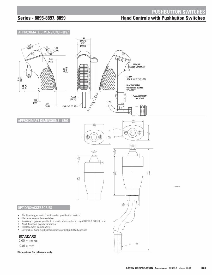
EATON CORPORATION Aerospace TF300-5 June, 2004 B23
Dimensions for reference only.
STANDARD0.00 = inches
[0,0] = mm
.250[6,35] TRIGGER MOVEMENT
PLUG AND CLAMPAN 1078-2
STRAP.094 [2,39] X .75 [19,05]
BLACK WEBBINGWITH BRASS BUCKLETIP & RIVET
.50[12,7]
2.0[50,8]
.063[1,60
1.563[39,70]
CABLE - 3 FT. LG.
1.69[42,9]
1.09[2,77]
2.05
[52,07]
18˚
5.28
[134
,1]
3.50
[88,
9]2.
34[5
9,4]
1.49[37,31]1.375
[34,93]
.72
[18,3]
1.58[40,1]
1.13
[28,
7]
.4[10,2]
.51
[13,
0]2.
96[7
5,2]
8899K 2.AI
1.58[40,1]
1.13
[28,
7]
.4[10,2]
.98[22.9]
ROD
.51
[13,
0]2.
96[7
5,2]
7.01
[178
,05]
AAPPPPRROOXXIIMMAATTEE DDIIMMEENNSSIIOONNSS -- 88889977
AAPPPPRROOXXIIMMAATTEE DDIIMMEENNSSIIOONNSS -- 88889999
OOPPTTIIOONNSS//AACCCCEESSSSOORRIIEESS
• Replace trigger switch with sealed pushbutton switch• Harness assemblies available• Auxiliary toggle or pushbutton switches installed in cap (8896K & 8897K type)• Multi-function switch variations• Replacement components• Joystick or hand-held configurations available (8899K series)
PUSHBUTTON SWITCHESSeries - 8895-8897, 8899 Hand Controls with Pushbutton Switches

B24 EATON CORPORATION Aerospace TF300-5 June, 2004
SSEELLEECCTTIIOONN TTAABBLLEE
8870K2 & K4 8909K559
PUSHBUTTON SWITCHESSeries - 8870, 8809 Special Designed Pushbutton Switches
FFEEAATTUURREESS
• All switches employ momentary action
• Foot or hand operation designs• Plunger has ice and mud scraper• Mechanical lock on 8909K559• Mechanical lock has spring loaded
release design• Logic to power switching load capability
SSPPEECCIIFFIICCAATTIIOONNSS
• MS approved and QPL'd to MIL-S-8805• Temperature Range: -40°F to +185°F
(-40°C to +85°C)• Life: 20,000 operations at rated load
50,000 operations mechanical life
CCUURRRREENNTT RRAATTIINNGGSS
Resistive Load
Inductive Load
Lamp Load
Resistive Load
Inductive Load
Lamp Load
8870K2 25 10 4 15 7.5 28870K3 25 10 4 15 7.5 28870K4 25 10 4 15 7.5 28870K5 25 10 4 15 7.5 28909K559 6 — — 6 — —
28VDC
115VAC
60 or 400Hz
Catalog
Number
8870K3 & K5
OOPPTTIIOONNSS//AACCCCEESSSSOORRIIEESS
• Terminal screws furnished assembled
• Double throw contacts - 8870
• Special marking
Poles and
Throw Normal Depressed Mounting Features
Government
Part Number
Catalog
Number
M8805/55-001 8870K2
1 P.S.T. OFF ON* Flush 2
Microphone PB Switches M8805/55-002 8870K3Foot Operated M8805/55-003 8870K4
M8805/55-004 8870K5
2 P.S.T. OFF ON* Flush 2
Roller Operated — 8909K5591
* Momentary contact.1
Electrical life of 8909K559 is 12,000 operations.2
See page B25 for mounting data.
Circuit Arrangement

EATON CORPORATION Aerospace TF300-5 June, 2004 B25
.625[15,88]
1.875[47,63]
.828[21,03]
.1.0
9[2
7,7]
1.10
9[2
8,17
]
.469[11,91]
.75[19,05]
#4-40 TAP4 HOLES
#5-40 X .25 [6,3] LONGBINDING HEAD SCREWS
Dimensions for reference only.
STANDARD0.00 = inches
[0,0] = mm
PUSHBUTTON SWITCHESSeries - 8870, 8809 Special Designed Pushbutton Switches
AAPPPPRROOXXIIMMAATTEE DDIIMMEENNSSIIOONNSS -- 88887700KK22,, KK33,, KK44,, KK55
AAPPPPRROOXXIIMMAATTEE DDIIMMEENNSSIIOONNSS -- 88990099KK555599
8870K5 2.968 1.660 6-32 UNC-2B
8870K4 2.218 .910 6-32 UNC-2B
8870K3 2.968 1.668 6-40 UNF-2B
8870K2 2.218 .910 6-40 UNF-2B
CAT.NO. A B INSERT & NUT THREAD
MAX
MAX
2.1602.160[54,86][54,86]
1.09
81.
098
[27,
89]
[27,
89]
"B"
"B"
MAX
MAX
"A"
"A"
MAX
MAX
#5-40 .250 [6.35] LG RD BDG HD SCREW#5-40 .250 [6.35] LG RD BDG HD SCREW#5 LOCKWASHER #5 LOCKWASHER
INTERNAL SWITCHINTERNAL SWITCHACTUATOR SEALACTUATOR SEAL
BARREL (BUSHING)BARREL (BUSHING)WIPING SEALWIPING SEAL
DIA.DIA.
#6-32 X .250 [6,35] LG RD HD SCREW#6-32 X .250 [6,35] LG RD HD SCREW#6 LOCKWASHER#6 LOCKWASHER
TERMINAL GTERMINAL GTERMINALSTERMINALS
1.8121.812[46,02][46,02]
1.3121.312[33,32][33,32]
.156.156[3,96][3,96]
.688.688[17,48][17,48]
MAXMAX.858.858
[21,80][21,80]
1.54
61.
546
[39,
27]
[39,
27]
.562.562[14,27][14,27]
MAX
MAX
1.30
01.
300
[33,
02]
[33,
02]
MAX

B26 EATON CORPORATION Aerospace TF300-5 June, 2004
NOTES
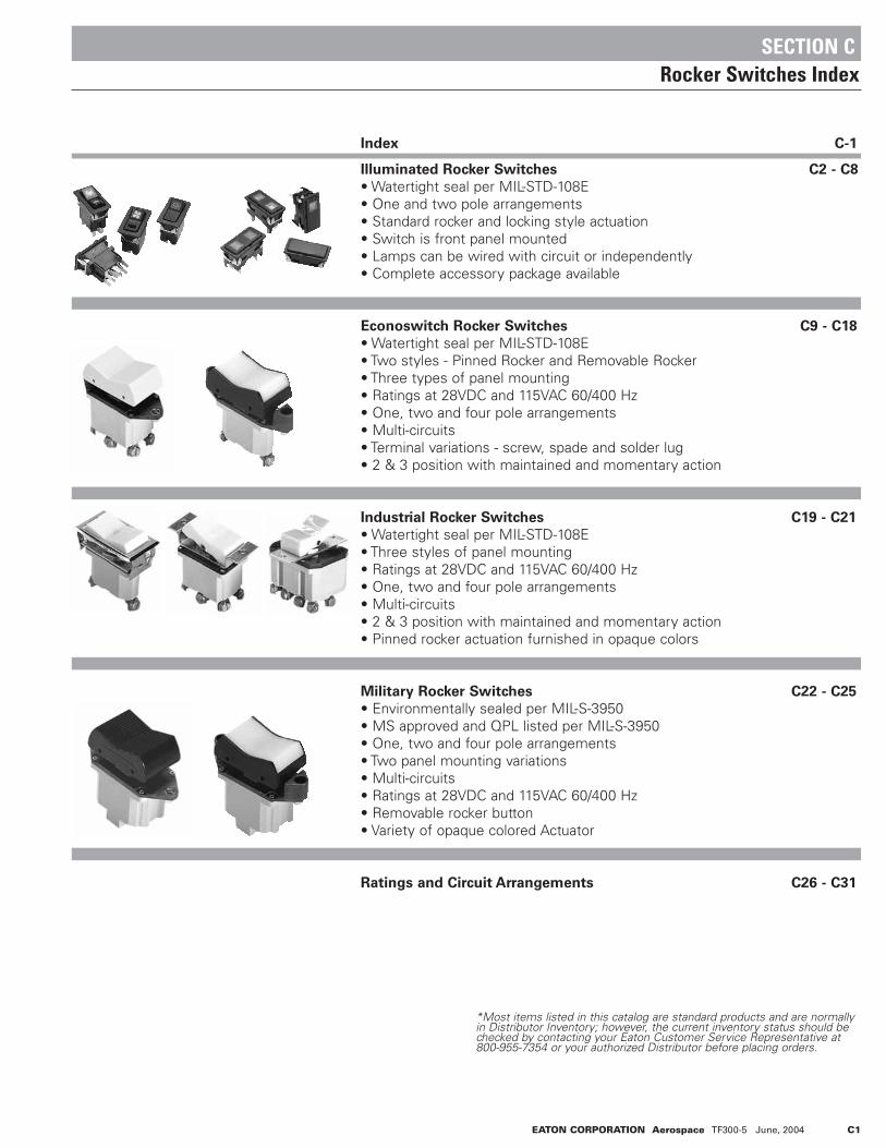
EATON CORPORATION Aerospace TF300-5 June, 2004 C1
Index C-1
Illuminated Rocker Switches C2 - C8
• Watertight seal per MIL-STD-108E• One and two pole arrangements• Standard rocker and locking style actuation• Switch is front panel mounted• Lamps can be wired with circuit or independently• Complete accessory package available
Econoswitch Rocker Switches C9 - C18
• Watertight seal per MIL-STD-108E• Two styles - Pinned Rocker and Removable Rocker• Three types of panel mounting• Ratings at 28VDC and 115VAC 60/400 Hz• One, two and four pole arrangements• Multi-circuits• Terminal variations - screw, spade and solder lug• 2 & 3 position with maintained and momentary action
Industrial Rocker Switches C19 - C21
• Watertight seal per MIL-STD-108E• Three styles of panel mounting• Ratings at 28VDC and 115VAC 60/400 Hz• One, two and four pole arrangements• Multi-circuits• 2 & 3 position with maintained and momentary action• Pinned rocker actuation furnished in opaque colors
Military Rocker Switches C22 - C25
• Environmentally sealed per MIL-S-3950• MS approved and QPL listed per MIL-S-3950• One, two and four pole arrangements• Two panel mounting variations• Multi-circuits• Ratings at 28VDC and 115VAC 60/400 Hz• Removable rocker button• Variety of opaque colored Actuator
Ratings and Circuit Arrangements C26 - C31
SECTION CRocker Switches Index
*Most items listed in this catalog are standard products and are normallyin Distributor Inventory; however, the current inventory status should bechecked by contacting your Eaton Customer Service Representative at800-955-7354 or your authorized Distributor before placing orders.

C2 EATON CORPORATION Aerospace TF300-5 June, 2004
The new Illuminater series of front panel mounted rocker switches are sealed to meet the watertight requirements of MIL-STD-108E. Product variationsare with standard or locking rocker Actuator, and single or double pole switching with multi-circuits. A variety of accessory items are also available. Thisproduct is ideally suited for use in harsh environmental applications.
"ILLUMINATER™ " SERIES SEALED ROCKER SWITCHES
DDEESSCCRRIIPPTTIIOONN
DDEESSIIGGNN FFEEAATTUURREESS
• Front panel mounted• Totally sealed switching chamber• Various circuit variations• Keyed assembly - actuator to bezel and base to connector• Removable rocker button• One or two lamp capability• Full size clear lens with non-glare surface• Icons located beneath lens surface (high wearability)• Diffusion lens alters icon background lighting• Minimum light leakage• Various locking styles available• Matte black textured finish on bezel/actuator• Molded-in terminal identification• Molded-in orientation mark
SSPPEECCIIFFIICCAATTIIOONNSS
• Watertight per MIL-STD-108E• Temperature range: -40°F to +160°F (-40°C to +71°C)• Dielectric strength 1800 V RMS @ sea level• Life: 50,000 cycles min. electrical; 100,000 cycles min. mechanical• Silver plated contact - standard• Flame retardant thermoplastic bezel and base• Stainless steel mounting clips
AACCCCEESSSSOORRIIEESS
• Indicator light assembly (see page C7)
• Filler plug (see page C6)
• Connector (see page C7)
• Gang mounting system
OOPPTTIIOONNSS
• Non-illuminated switch
• Gold plated contacts

EATON CORPORATION Aerospace TF300-5 June, 2004 C3
SPADE TERMINALS.032 THK. X .25 WIDEFINISH: TIN PLATED
.078(1.98)
.54 (13.72)
2.00 (50.8)
LAMP TERMINAL
SWITCH TERMINAL
MOUNTING ORIEN TATIONDESIGNATES TOP ORLEFT SWITCH MOUNTING
AB
1 32
CD
4 65
KEYSIDE
1.05(26.67
2.05(52.07)
DRAINSLOTS
ARROWS LOCATED ON UNDERSIDEARROWS LOCATED ON UNDERSIDEOF SWITCH DESIGNATE SWITCHOF SWITCH DESIGNATE SWITCHMOUNTING DIRECTIONMOUNTING DIRECTION
LEFTLEFT RIGHTRIGHT
KEYSIDEKEYSIDE
TOPTOP
KEYSIDEKEYSIDEBOTTOMBOTTOM
KEYSIDEKEYSIDE RIGHT ORRIGHT ORBOTTOMBOTTOM
LOCKLOCKACTUATORACTUATOR
.40 (10,16).40 (10,16)
LEFT ORLEFT ORTOPTOP
"ILLUMINATER™ " SERIES ENGINEERING DATA
SSIINNGGLLEE PPOOLLEE EELLEECCTTRRIICCAALL RRAATTIINNGGSS DDOOUUBBLLEE PPOOLLEE EELLEECCTTRRIICCAALL RRAATTIINNGGSS
Maintained 25 15 7.5 20 15 5Momentary 20 10 6 15 10 4
6 & 14VDC 28VDCResistive
LoadInductive
LoadLamp Load
Resistive Load
Inductive Load
Lamp Load
Type of Operation
Maintained 30 20 10 20 15 7Momentary 25 15 7.5 18 10 5
6 & 14VDC 28VDCType of
OperationResistive
LoadInductive
LoadLamp Load
Resistive Load
Inductive Load
Lamp Load
Note: For recommended panel cutout dimensions, see page C7.
FIGURE 1
Horizontal Mount
FIGURE 2
Vertical Mount
FIGURE 3
Locking Actuator Styles 4, 5,Y, & T
FIGURE 4
Locking Actuator Styles 6, 7, W, & S
DDIIMMEENNSSIIOONNSS

C4 EATON CORPORATION Aerospace TF300-5 June, 2004
AACCTTUUAATTOORR SSTTYYLLEE (See Page C3, Figs 1-4)
Code
1
2
3
4
5
6
7
A
S
T
W
Y
Style
(1) Lens Top or Left(1) Lens Bottom or Right(2) LensesLock in both End Positions w/ Lens (or Plain Surface)Top or LeftLock in Center Position w/ Lens (or Plain Surface) Topor LeftLock in Both End Positions w/ Lens (or Plain Surface)Bottom or RightLock in Center Position w/Lens (or Plain Surface)Bottom or RightPlain Rocker Button (No Lenses)Lock in (1) End Position w/ Lens (or Plain Surface)Bottom or Right (Lens or Plain Surface Locked in "UP"PositionLock in (1) End Position w/ Lens (or Plain Surface) Topor Left (Lens or Plain Surface Locked in "UP" PositionLock in (1) End Position w/ Lens (or Plain Surface)Bottom or Right (Lens or Plain Surface LockedActuated Position)Lock in (1) End Position w/ Lens (or Plain Surface) Topor Left (Lens or Plain Surface Locked ActuatedPosition)
AACCTTUUAATTOORR MMOOUUNNTTIINNGGPPOOSSIITTIIOONN && CCOOLLOORR
Code
F
H
V
Orientation
Optional / Black (Plain Actuator no Lenses)Horizontal / BlackVertical / Black
OOPPTTIIOONNAALL FFEEAATTUURREESS
Code
A
G
Option
Silver ContactsGold Contacts
RROOCCKKEERR TTYYPPEE
Code
5
6
7
8
Type
IlluminatedNon - IlluminatedLocking Feature IlluminatedLocking Feature Non-Illuminated
LLAAMMPP SSEELLEECCTTIIOONN
Code
D
E
F
G
H
J
K
L
M
ZCCIIRRCCUUIITT AARRRRAANNGGEEMMEENNTT
Code
01
02
03
04
05
06
07
08
09
10
11
12
13
*14
Code
* 15
* 16
50
51
52
53
54
55
56
57
58
59
* 60
Top
or Left
OnMom OnOnOn OnOnNoneOnOnOnOffMom OnOnOn
Center
OffOffOffNoneNoneOffOffMom OffNoneNoneNoneOnOnOn
Bottom
or Right
OnMom OnMom OnOnMom OnNoneMom OnNoneOffMom OffMom OnNoneNoneOn
Available
Locking
Configuration
4,5,6,7,Y,T,S5,7
5,7,Y,S4,6,Y,W,T,S,
Y,S5,Y7Y
4,6,Y,W,T,SY,SY,S5
5,Y4,5,6,7,Y,W,T,S
Voltage
14VDC14VDC14VDC28VDC28VDC28VDCSee1See1See1
No. Lamps
112112112
Location
Top or LeftBottom or RightBoth LocationsTop or LeftBottom or RightBoth LocationsTop or LeftBottom or RightBoth Locations
Top
or Left
OnMom OnMom OnMom OnNoneMom OnNoneOffMom OffMom OnNoneNoneMom On
Center
OnOnOffNoneOffOffMom OffNoneNoneNoneOnOnOn
Bottom
or Right
Mom OnMom OnOnOnOnNoneOnOnOnOffMom OnOnOn
Available
Locking
Configuration
5,7,Y,S5,7
5,7,W,TW,T7,W5W
4,6,Y,W,T,SW,TW,T
77,W
5,7,W,T
Non - Illuminating
1 Furnished without lamps. Provisions for lamp available as indicated under location.
* Double pole switches only
"ILLUMINATER™ " SERIES PART NUMBERING SYSTEM
IICCOONN (Location - Top or Left “only”)(See Page C8 for Icon Selection Table)
Code
DF
Function
Oil
(Code “ZZ” = No Icon)
IICCOONN (Location - Bottom or Right “only”)(See Page C8 for Icon Selection Table)
Code
BF
Function
Horn
(Code “ZZ” = No Icon)
DDIIFFFFUUSSIIOONN LLEENNSS CCOOLLOORR(Location - Top or Left “only”)
Code
0
1
2
3
4
5
6
Color
NoneAmberBlueGreenRedWhiteClear
DDIIFFFFUUSSIIOONN LLEENNSS CCOOLLOORR(Location - Bottom or Right “only”)
Code
0
1
2
3
4
5
6
Color
NoneAmberBlueGreenRedWhiteClear
BBAAFFFFLLEE (Light Intensity Deflector)
Code
A
B
C
Z
Color
(1) Top or Left(1) Bottom or Right(2) BafflesNone
PPAARRTT NNUUMMBBEERR WWOORRKKSSHHEEEETT
No.
of
Pole
sC
ircui
t Arr
ange
men
tB
ezel
Col
orB
ezel
Sty
leLa
mp
Sele
ctio
nM
ount
ing
Posi
tion
Act
uato
r St
yle
Icon
- To
p or
Lef
tD
iffus
ion
Lens
Col
orIc
on -
Bot
tom
or
Rig
htD
iffus
ion
Lens
Col
or
B 01 A 5 J H 3 DF 2 ZZ 3 Z = B01A5JH3DF2ZZ3Z
Diff
usio
n Le
ns C
olor
NNOO.. OOFF PPOOLLEESS
Code
A
B
Selection
SingleDouble
B 01 A 5 J H 3 DF 2 ZZ 3 Z

EATON CORPORATION Aerospace TF300-5 June, 2004 C5
Along with this new line of illuminated rocker switches, we also offer a line of accessories. General styling and appearance match those of the basic switch, with design fea-
tures as stated.
"ILLUMINATER™ " SERIES INDICATOR AND ACCESSORIES
DDEESSCCRRIIPPTTIIOONN
DDEESSIIGGNN FFEEAATTUURREESS
Indicator
• Front panel mounted
• Keyed assembly
- indicator lens assembly to bezel
- connector to bezel superstructure
• Removable indicator lens assembly
• One or two lamp capability
• Full size clear lens with non-glare surface
• Icons located beneath lens surface
• Diffusion lens alters icon background lighting
• Matte black textured finish on indicator assembly
• Molded-in terminal identification
• Molded-in orientation mark
SSPPEECCIIFFIICCAATTIIOONNSS // MMAATTEERRIIAALLSS
• Temperature range: -40°F to +160°F (-40°C to +71°C)
• Flame retardant thermoplastic bezel and base
• Stainless steel mounting clips
OOTTHHEERR AACCCCEESSSSOORRIIEESS
• Connector (see page C7)
FFIILLLLEERR PPLLUUGG
• Front panel mounted
• Accepts - connector/harness assembly
• Matte black textured finish

C6 EATON CORPORATION Aerospace TF300-5 June, 2004
Note: For recommended panel cutout dimensions, see page C7.
1.05(26.67)
2.05(52.07)
SUPER STRUCTURE LAMP
DRAIN SLOTS
SPADE TERMINALS.032 THK. X .25 WIDEFINISH: TIN PLATED
MOUNTING ORIEN TATIONDESIGNATES TOP OR LEFTINDICATOR LIGHT MOUNTINGDIRECTION
BAC
D
LAMP TERMINALIDENTIFICATION
1.38(35.05)
.156(3.96)
USA
1 .05(26 .67)
2 .05(52 .07)
.87(22 .10)
.16 (4 .06)
DRAINSLOTS
"ILLUMINATER™ " SERIES INDICATOR AND ACCESSORIES ENGINEERING DATA
IINNDDIICCAATTOORR
FFIILLLLEERR PPLLUUGG -- PP//NN PP2244001100

LEFTLEFT RIGHTRIGHT
TOPTOP
BOTTOMBOTTOM 1.860 .005(47.24)
.963
.00
5(2
4.46
)
R .06 MAX.PERMISSIBLE
EATON CORPORATION Aerospace TF300-5 June, 2004 C7
DIMENSIONS AND PANEL THICKNESS
LLAAMMPP SSEELLEECCTTIIOONN PPAARRTT NNUUMMBBEERR WWOORRKKSSHHEEEETT
Code
D
E
F
G
H
J
K
L
M
Voltage
14VDC14VDC14VDC28VDC28VDC28VDCSee1See1See1
No.
Lamps
112112112112
Location
Top or LeftBottom or RightBoth LocationsTop or LeftBottom or RightBoth LocationsTop or LeftBottom or RightBoth Locations
IINNDDIICCAATTOORR SSTTYYLLEE (See Page C7, Figs. 1&2)
Code
1
2
3
Style
Lens Top or LeftLens Bottom or RightTwo Lenses
MMOOUUNNTTIINNGG PPOOSSIITTIIOONN// CCOOLLOORR
Code
D
E
INDICATOR
SUPERSTRUCTURE
Color
Horizontal/ BlackVertical/ Black
BBEEZZEELL CCOOLLOORR
Code
B
Color
Black
BBEEZZEELL SSTTYYLLEE
Code
5
Style
Indi
cato
r Su
pers
truc
ture
Bez
el C
olor
Bez
el S
tyle
Lam
p Se
lect
ion
Mou
ntin
g Po
sitio
nIn
dica
tor
Styl
eIc
on -
Top
or L
eft
Diff
. Len
s C
olor
Icon
- B
ot. o
r R
ight
Diff
. Len
s C
olor
Lam
p Se
lect
ion
DDIIFFFFUUSSIIOONN LLEENNSS CCOOLLOORR(Location - Top or Left "only")
Code
0
1
2
3
4
5
6
Color
NoneAmberBlueGreenRedWhiteClear
DDIIFFFFUUSSIIOONN LLEENNSS CCOOLLOORR(Location - Bottom or Right "only")
Code
0
1
2
3
4
5
6
Color
NoneAmberBlueGreenRedWhiteClear
Code
DF
Function
Oil
(Code "ZZ" = No Icon)
IICCOONN (Location - Bottom or Right "only")(See Page C8 for Icon Selection Table)
Code
BF
Function
Horn
(Code "ZZ" = No Icon)
1 Furnished without lamps. Provisions for lamp available as indicated under location.
Connector Shell P/N 17-19388.Figure 1
Horizontal Mount.
Mounting orientation shown on bottom of base designatestop or left indicator light mounting direction.
Recommended Metal Panel Thickness.040 (1.02) to .140 (3.56)
Figure 2
Vertical Mount
ROO B 5 J K 3 DF 2 ZZ 3 Y
ROO Y
ROO Y
ROO Y
"ILLUMINATER™ " SERIES INDICATOR PART NUMBERING SYSTEM
IICCOONN (Location - Top or Left "only")(See Page C8 for Icon Selection Table)
ROO B 5 J D 3 DF 2 ZZ 3 Y = ROOB5JD3DF2ZZ3Y
AACCCCEESSSSOORRYY IITTEEMM IINNDDIICCAATTOORR SSTTYYLLEE RREECCOOMMMMEENNDDEEDD PPAANNEELL CCUUTTOOUUTT
.98±.030(24.89)
.93±.030(23.62)
1.68
±.0
30(4
2.67
)
USA
4
5
6
1
2
3
B A
D C
LEFT RIGHT
TOP
BOTTOM 1.860 .0051.860 .005(47.24)(47.24)
.963
.00
5.9
63 .
005
(24.
46)
(24.
46)
R .06 MAX.R .06 MAX.PERMISSIBLEPERMISSIBLE

Code Description SAE Spec.
No.J1632
-DF Oil 1056
-CW Level Indicator 0159
-DG Temperature 0034
-DA On/Start 5007
-DB Off/Stop 5008
-BF Horn 0244
-BT Fast None
-BV Slow None
-CN Lock 1656
-CR Unlock None
-DH Rearward Moving NoneMachine Alarm
-DJ Rearward Moving NoneMachine Alarm-CANCEL
-BU Engine-Basic Symbol 1156
-CK Engine-Electrical 1704Preheat (Low Temperature Start Aid)
-AJ Engine-Gas Injection 1547(Low Temperature Start Aid)
-BZ Transmission-Basic Symbol 1166
-BL Fuel or Fuel System 0245Basic Symbol
-AX Headlights - High/Upper 0082Beam
-AY Headlights - Low/Dipped 0083Beam
-AZ Work Light 1204
-DK Parking Lights 0240
-CJ Hazard Warning Lights 0085
-BB Interior Dome Light 1421
-BC Beacon 1141
-DL Turn Signals 0084
-DM Front Fog Lights 0633
-CE Rear Fog Lights 0634
-BA Instrument Illumination 1556
-BG Windshield-Wiper 0086
-BH Windshield Washer 0088
-CU Windshield - Washer & 0087Wiper
-BJ Rear Window - Wiper 0097
-BK Rear Window - Washer 0099
-DN Rear Window - Washer & 0098Wiper
-AA Heater/Interior Heating 0637
-BE Air Conditioning/Cooling 0027System
-BD Ventilating/Air Circulating 0089Fan
C8 EATON CORPORATION Aerospace TF300-5 June, 2004
"ILLUMINATER™ " SERIES ICON SELECTION TABLE
Code Description SAE Spec.
No. J1632
Typical icons illustrated are per SAE Pub No.s: J-107, J-1048, and J-1449. Additional icons are available upon request.Note: If no icon is required, enter cod “ZZ”.
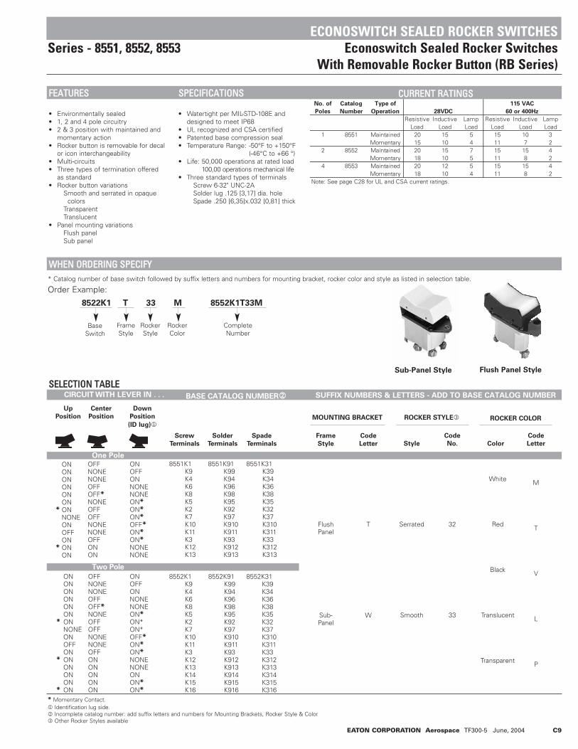
EATON CORPORATION Aerospace TF300-5 June, 2004 C9
CIRCUIT WITH LEVER IN . . . BASE CATALOG NUMBER2
One Pole
Two Pole
SUFFIX NUMBERS & LETTERS - ADD TO BASE CATALOG NUMBER
Up
Position
Center
Position
Down
Position
(ID lug)1
ONONONONONON
* ONNONEONOFFON
* ONON
ONONONONONON
* ONNONEONOFFON
* ONONONON
* ON
OFFNONENONEOFFOFF*NONEOFFOFFNONENONEOFFON ON
OFFNONENONEOFFOFF*NONEOFFOFFNONENONEOFFONONONONON
ONOFF ONNONENONEON*ON*ON*OFF*ON*ON*NONENONE
ONOFFONNONENONEON*ON*ON*OFF*ON*ON*NONENONEONON*ON*
8551K1K9K4K6K8K5K2K7K10K11K3K12K13
8552K1K9K4K6K8K5K2K7K10K11K3K12K13K14K15K16
8551K91K99K94K96K98K95K92K97K910K911K93K912K913
8552K91K99K94K96K98K95K92K97K910K911K93K912K913K914K915K916
8551K31K39K34K36K38K35K32K37K310K311K33K312K313
8552K31K39K34K36K38K35K32K37K310K311K33K312K313K314K315K316
FlushPanel
Sub-Panel
T
W
Serrated
Smooth
32
33
White
Red
Black
Translucent
Transparent
M
T
V
L
P
Screw
Terminals
Frame
Style
Code
Letter Style
Code
No. Color
Code
Letter
MOUNTING BRACKET
Solder
Terminals
ROCKER STYLE3 ROCKER COLOR
Spade
Terminals
SSEELLEECCTTIIOONN TTAABBLLEE
* Catalog number of base switch followed by suffix letters and numbers for mounting bracket, rocker color and style as listed in selection table.
Order Example:
8522K1 T 33 M 8552K1T33M
* Momentary Contact.1 Identification lug side.2 Incomplete catalog number: add suffix letters and numbers for Mounting Brackets, Rocker Style & Color3 Other Rocker Styles available
Sub-Panel Style Flush Panel Style
BaseSwitch
FrameStyle
RockerStyle
RockerColor
CompleteNumber
ECONOSWITCH SEALED ROCKER SWITCHESSeries - 8551, 8552, 8553 Econoswitch Sealed Rocker Switches
With Removable Rocker Button (RB Series)
No. of
Poles
Catalog
Number
Type of
Operation
1 8551 Maintained 20 15 5 15 10 3Momentary 15 10 4 11 7 2
2 8552 Maintained 20 15 7 15 15 4 Momentary 18 10 5 11 8 24 8553 Maintained 20 12 5 15 15 4 Momentary 18 10 4 11 8 2
Note: See page C28 for UL and CSA current ratings.
28VDC
115 VAC
60 or 400Hz
Resistive Load
Inductive Load
Resistive Load
Inductive Load
Lamp Load
Lamp Load
WWHHEENN OORRDDEERRIINNGG SSPPEECCIIFFYY
CCUURRRREENNTT RRAATTIINNGGSSFFEEAATTUURREESS
• Environmentally sealed • 1, 2 and 4 pole circuitry• 2 & 3 position with maintained and
momentary action• Rocker button is removable for decal
or icon interchangeability• Multi-circuits• Three types of termination offered
as standard• Rocker button variations
Smooth and serrated in opaque colors
TransparentTranslucent
• Panel mounting variationsFlush panelSub panel
SSPPEECCIIFFIICCAATTIIOONNSS
• Watertight per MIL-STD-108E and designed to meet IP68
• UL recognized and CSA certified• Patented base compression seal• Temperature Range: -50°F to +150°F
(-46°C to +66 °)• Life: 50,000 operations at rated load
100,00 operations mechanical life• Three standard types of terminals
Screw 6-32" UNC-2ASolder lug .125 [3,17] dia. holeSpade .250 [6,35]x.032 [0,81] thick

C10 EATON CORPORATION Aerospace TF300-5 June, 2004
CIRCUIT WITH LEVER IN . . . BASE CATALOG NUMBER2
Four Pole
SUFFIX NUMBERS & LETTERS - ADD TO BASE CATALOG NUMBER
Up
Position
Center
Position
Down
Position
(ID lug)1
ONONONONONON
* ONNONEONOFFON
* ONONONON
* ON
OFFNONENONEOFFOFF*NONEOFFOFFNONENONEOFFONONONONON
ONOFFONNONENONEON*ON*ON*OFF*ON*ON*NONENONEONON*ON*
8553K1K9K4K6K8K5K2K7K10K11K3K12K13K15K16K17
8553K91K99K94K96K98K95K92K97K910K911K93K912K913K915K916K917
8553K31K39K34K36K38K35K32K37K310K311K33K312K313K315K316K317
FlushPanel
Sub-Panel
T
W
Serrated
Smooth
32
33
White
Red
Black
Translucent
Transparent
M
T
V
L
P
Screw
Terminals
Frame
Style
Code
Letter Style
Code
No. Color
Code
Letter
MOUNTING BRACKET
Solder
Terminals
ROCKER STYLE3 ROCKER COLOR
Spade
Terminals
SSEELLEECCTTIIOONN TTAABBLLEE,, CCOONN’’TT..
* Momentary circuit.
See pages C26-C27 and C29-C31 for circuit diagrams.1 Identification lug side.2 Incomplete catalog number: add suffix letters and numbers for Mounting Brackets, Rocker Style & Color3 Other Rocker Styles available
Dimensions for reference only.
90-9618.AIC- ,8851
1.30
[33,
02]
.57
[14,
48]
.27[6,86]
.53
[13,
46]
6-32 UNC-2A TERMINAL SCREW, SEMS .125 DIA.HOLE[3,18]
2SOLDER LUG1 3 2
SPADE TERMINAL1 32
SCREW TERMINAL1 3
IDENTIFICATION TAB
6-32 UNC LOCKNUT
.73R[18,54]
MAX
.
1.60
[40,
64]
SUB
PANE
L M
TG.
1.28
[32,
51]M
AX.
SUB
PANE
L M
TG.
1.51
[38,
35]M
AX.
SUB
PANE
L M
TG.
FLUS
H PA
NEL
MTG
.
MAX
.
1.58
[40,
13]
FLUS
H PA
NEL
MTG
.
MAX
.
1.81
[45,
97]
FLUS
H PA
NEL
MTG
.
MAX
.
33˚
16˚
.94
[23,
88]
.870
[22,
10]
1.812[46,02]
2.125[53,98]
TOTAL TRAVEL
1.812[46,02]
1.51[38,35]
.150 [3,81]
.594
[15,
09]
1.25[31,75]
.250[6,35] X .032[0.81] THK.
DIA.
RECOMMENDEDPANEL CUT-OUT
ECONOSWITCH SEALED ROCKER SWITCHESSeries - 8551, 8552, 8553 Econoswitch Sealed Rocker Switches
With Removable Rocker Button (RB Series)
MMOOUUNNTTIINNGG DDIIMMEENNSSIIOONNSS -- OONNEE PPOOLLEE // 88555511
STANDARD0.00 = inches
[0,0] = mm

EATON CORPORATION Aerospace TF300-5 June, 2004 C11
Dimensions for reference only.
STANDARD0.00 = inches
[0,0] = mm
.250[6,35]X .032[0,81] THK.
.27
1.34
.57
.53
6-32 UNC-2A TERMINAL SCREW,SEMS
4 5 6
1 2
SCREW TERMINAL
3
.125[3,18] DIA. HOLE
IDENTIFICATION TAB
1.32
6-32-UNC LOCKNUT
.73R
MAX
.
1.64
SUB
PANE
L M
TG.
1.32
MAX
.SU
B PA
NEL
MTG
.
1.55
MAX
.SU
B PA
NEL
MTG
.
FLUS
H PA
NEL
MTG
.
MAX
.
1.62
FLUS
H PA
NEL
MTG
.
MAX
.
1.85
FLUS
H PA
NEL
MTG
.M
AX.
33û16.5û
.870
.89
4 5 6
1 2
SOLDER LUG
3
4 5 6
1 2
SPADE TERMINAL
3
1.812
2.125
.94
1.812
1.51 .150
TOTAL TRAVEL
DIA.
RECOMMENDE DPANEL CUT-OUT
1.34
[34,
04]
.57
[14,
48]
.53
[13,
46]
1.32[33,53]
6-32 UNC-2A TERMINAL SCREW,SEMS
.125[3,18]
DIA. HOLE
1110 12
8
7
1110 12
8
7
1110 12
8
IDENTIFICATION TAB
6-32 UNC LOCKNUT
.73 R[18,54]
MAX
.
1.64
[41,
66]
SUB
PANE
L M
TG.
1.32
[33,
53]M
AX.
SUB
PANE
L M
TG.
1.55
[39,
37]M
AX.
SUB
PANE
L M
TG.
FLUS
H PA
NEL
MTG
.
MAX
.
1.62
[41,
15]
FLUS
H PA
NEL
MTG
.
MAX
.
1.85
[46,
99]
FLUS
H PA
NEL
MTG
.
MAX
.
33˚16˚
.94
[23,
88]
.870
[22,
10]
1.812[46,02]
2.125[53,98]
1.812[46,02]
1.51[38,35]
.150 [3,81]
.250[6,35] X .032[0,81] THK
.27[6,86]
TOTAL TRAVEL
RECOMMENDED PANEL CUT-OUT
DIA.
.5
ECONOSWITCH SEALED ROCKER SWITCHESSeries - 8551, 8552, 8553 Econoswitch Sealed Rocker Switches
With Removable Rocker Button (RB Series)
MMOOUUNNTTIINNGG DDIIMMEENNSSIIOONNSS -- TTWWOO PPOOLLEE // 88555522
MMOOUUNNTTIINNGG DDIIMMEENNSSIIOONNSS -- FFOOUURR PPOOLLEE // 88555533

C12 EATON CORPORATION Aerospace TF300-5 June, 2004
ECONOSWITCH SEALED ROCKER SWITCHESSeries - 8551, 8552, 8553 Econoswitch Sealed Rocker Switches
With Removable Rocker Button (RB Series)
OOPPTTIIOONNSS//AACCCCEESSSSOORRIIEESS
• Special color rockers
• Hot stamped lettering on rockers - smooth rockers only
• Special marking on switches
• Optional Actuator
• Gold plated contacts
RREEPPLLAACCEEMMEENNTT SSMMOOOOTTHH BBUUTTTTOONN SSEELLEECCTTIIOONN TTAABBLLEE
Color Part Number
White 53-2161-2
Red 53-2161-3
Black 53-2161-4
Translucent 53-2415
Transparent 53-2161-6

EATON CORPORATION Aerospace TF300-5 June, 2004 C13
CIRCUIT WITH LEVER IN . . . BASE CATALOG NUMBER11
One Pole
Two Pole
SUFFIX NUMBERS & LETTERS - ADD TO BASE CATALOG NUMBER
Up
Position
Center
Position
Down
Position
(Keyway)
ONONONONONON
* ONNONEONOFFON
* ONON
ONONONONONON
* ONNONEONOFFON
* ONONONON
* ON
OFFNONENONEOFFOFF*NONEOFFOFFNONENONEOFFONON
OFFNONENONEOFFOFF*NONEOFFOFFNONENONEOFFONONONONON
ONOFFONNONENONEON*ON*ON*OFF*ON*ON*NONENONE
ONOFFONNONENONEON*ON*ON*OFF*ON*ON*NONENONEONON*ON*
8554K1K9K4K6K8K5K2K7K10K11K3K12K13
8555K1K9K4K6K8K5K2K7K10K11K3K12K13K14K15K16
8554K91K99K94K96K98K95K92K97K910K911K93K912K913
8555K91K99K94K96K98K95K92K97K910K911K93K912K913K914K915K916
8554K31K39K34K36K38K35K32K37K310K311K33K312K313
8555K31K39K34K36K38K35K32K37K310K311K33K312K313K314K315K316
Sub-PanelMounting- ClearanceHoles
Sub-PanelMounting- Tapped Holes
Flush PanelMounting- ClearanceHoles
Flush PanelMounting- Tapped Holes
Snap-in BezelMounting
0.152
6-32UNC-2B
0.152
6-32UNC-2B
---
R
W
S
T
X
Serrated
Smooth
32
33
M
V
T
White
Black
Red
Screw
Terminals
Frame
Style
Mounting
Holes
Code
Letter Style
Code
No.
Code
LetterColor
MOUNTING BRACKET
Solder
Terminals
ROCKER STYLE ROCKER COLOR
Spade
Terminals
SSEELLEECCTTIIOONN TTAABBLLEE
• Catalog number of base switch followed by suffix letters and numbers for mounting bracket, rocker color and style as listed in selection table.
Order Example:
8555K1 S 32 M 8555K1S32M
One Pole
Snap-in Bezel
Mounting
Two Pole
Flush Panel
Mounting
Four Pole
Sub-Panel
Mounting
BaseSwitch
MountingBracket
RockerStyle
RockerColor
CompleteNumber
ECONOSWITCH SEALED ROCKER SWITCHESSeries - 8554, 8555, 8556 Econoswitch Sealed Rocker Switches
No. of
Poles
Catalog
Number
Type of
Operation
1 8554 Maintained 20 15 5 15 10 3Momentary 15 10 4 11 7 2
2 8555 Maintained 20 15 7 15 15 4 Momentary 18 10 5 11 8 24 8556 Maintained 20 12 5 15 15 4 Momentary 18 10 4 11 8 2
Note: See page C28 for UL and CSA current ratings.
28VDC
115 VAC
60 or 400Hz
Resistive Load
Inductive Load
Resistive Load
Inductive Load
Lamp Load
Lamp Load
WWHHEENN OORRDDEERRIINNGG SSPPEECCIIFFYY .. .. ..
CCUURRRREENNTT RRAATTIINNGGSSFFEEAATTUURREESS
• Environmentally sealed• 1, 2 and 4 pole circuitry• 2 & 3 position with maintained and
momentary action• Pinned rocker button• Rocker button style and color
variations• Multi-circuits• Thermoplastic rocker buttons in
opaque colors (serrated and smooth face)
• Panel mounting variationsFlush panelSub-panelSnap-in
SSPPEECCIIFFIICCAATTIIOONNSS
• Watertight per MIL-STD-108E and designed to meet IP68
• UL recognized and CSA certified• Temperature range: -50°F to +150°F
(-46°C to + 66°C)• Life: 50,000 operations at rated load
100,000 operations mechanical life• Three standard types of terminals
Screw 6-32 UNC-2ASolder lug .125 [3,17] dia. holeSpade .250 [6,35] x .032 [0.82] thick
* Momentary Contact.

C14 EATON CORPORATION Aerospace TF300-5 June, 2004
CIRCUIT WITH LEVER IN . . . BASE CATALOG NUMBER11
Four Pole
SUFFIX NUMBERS & LETTERS - ADD TO BASE CATALOG NUMBER
Up
Position
Center
Position
Down
Position
(Keyway)
ONONONONONON
* ONNONEONOFFON
* ONONONON
* ON
OFFNONENONEOFFOFF*NONEOFFOFFNONENONEOFFONONONONON
ONOFFONNONENONEON*ON*ON*OFF*ON*ON*NONENONEONON*ON*
8556K1K9K4K6K8K5K2K7K10K11K3K12K13K15K16K17
8556K91K99K94K96K98K95K92K97K910K911K93K912K913K915K916K917
8556K31K39K34K36K38K35K32K37K310K311K33K312K313K315K316K317
Sub-PanelMounting-ClearanceHoles
Sub-PanelMounting-Tapped Holes
Flush PanelMounting-ClearanceHoles
Flush PanelMounting-Tapped Holes
Snap-in BezelMounting
0.152
6-32UNC-2B
0.152
6-32UNC-2B
---
R
W
S
T
X
Serrated
Smooth
32
33
M
V
T
White
Black
Red
Screw
Terminals
Style Mounting
Holes
Code
Letter Style
Code
No.
Code
LetterColor
MOUNTING BRACKET
Solder
Terminals
ROCKER STYLE ROCKER COLOR
Spade
Terminals
SSEELLEECCTTIIOONN TTAABBLLEE
* Momentary contact.
See pages C26-C27 and C29-C31 for circuit diagrams.1 Incomplete Catalog Number - add suffix letters and numbers for Mounting Bracket, Rocker Style and Rocker Color - see "When Ordering Specify."
Dimensions for reference only.
STANDARD0.00 = inches
[0,0] = mm
ECONOSWITCH SEALED ROCKER SWITCHESSeries - 8554, 8555, 8556 Econoswitch Sealed Rocker Switches

EATON CORPORATION Aerospace TF300-5 June, 2004 C15
MMOOUUNNTTIINNGG DDIIMMEENNSSIIOONNSS -- OONNEE PPOOLLEE // 88555544
ECONOSWITCH SEALED ROCKER SWITCHESSeries - 8554, 8555, 8556 Econoswitch Sealed Rocker Switches
MMOOUUNNTTIINNGG DDIIMMEENNSSIIOONNSS -- SSNNAAPP--IINN BBEEZZEELL OONNEE PPOOLLEE // 88555544
.670 MAX
.900 ± .015
1.550 ± .015
.61 ± .01R KEYWAY .218 ± .065.336 ± .065
.076 ± .043
.030 ± .015
NOTE: WIRES ATTACHED TO THIS SWITCH MUST HAVE RING LUGS TO FIT #5 SCREW. DO NOT USE SPADE LUG OR WARP WIRE AROUND TERMINAL SCREW
6-32 UNC-2ATERMINAL SCREW
SCREW TERMINAL
6-32 UNC-2ATERMINAL SCREWS, SEMS
.07
.04
1.25 ± .02
.594 ± .020
1.55 ±
.030 ±
.015
.060 ±
.023
1.6
8 M
AX
.125 ± .010 DIA. HOLE
1.66 MAX
.250 ± .005 X .032 ± .002 THK.
1.89 MAX
1.19
1.45RECOMMENDED PANEL THICKNESS: .040 TO .140
.680 .830
SOLDER LUG SPADE TERMINAL
RECOMMENDED PANEL CUT-OUT
2SOLDER LUG1 3 2
SPADE TERMINAL1 32
6-32 UNC-2A TERMINAL SCREW,SEMS .125[3,18] DIA. HOLE .250[6,35]X.032[0,81] THK
SCREW TERMINAL1 3
.870
1.25.6
90.718
.670
1.625
1.937
1.250
1.63
MAX
.
1.35
SUB
PANE
L M
TG.
FLUS
H PA
NEL M
TG.
1.65
.382
MAX
.
FLUS
H PA
NEL M
TG.
MAX
.
1.33
SUB
PANE
L M
TG.
MAX
.
1.56
SUB
PANE
L M
TG.
MAX
.
1.86
MAX
.
FLUS
H PA
NEL M
TG.
.098
.253
.61R
.674
.545
.388KEYWAY
RECOMMENDE DPANEL CUT-OUT
MTG. HOLES 2 REQ.6-32 UNC-2B
.152[3,86

C16 EATON CORPORATION Aerospace TF300-5 June, 2004
RECOMMENDE DPANEL CUT-OUT
.718
.690
.167
0
1.625
1.937
1.250
6-32 UNC-2A TERMINAL SCREW,SEMS .125[3,18] DIA. HOLE .250[6,35] X .032[0,81]
1.67
MAX
.
1.39
SUB
PANE
L M
TG.
FLUS
H PA
NEL M
TG.
1.69
.382
MAX
.
FLUS
H PA
NEL M
TG.
MAX
.
1.37
SUB
PANE
L M
TG.
SUB
PANE
L M
TG.
MAX
.
1.60
MAX
.
1.90
MAX
.
FLUS
H PA
NEL M
TG..098
.253
.61R
.674
.545
.388KEYWAY
4 5 6
1 2
SCREW TERMINAL
3
1.32
.89
4 5 6
1 2
SOLDER LUG
3
4 5 6
1 2
SPADE TERMINAL
3
.648
6-32 UNC-2B.152 [3,86] DIA.
MTG HOLES
ECONOSWITCH SEALED ROCKER SWITCHESSeries - 8554, 8555, 8556 Econoswitch Sealed Rocker Switches
MMOOUUNNTTIINNGG DDIIMMEENNSSIIOONNSS -- TTWWOO PPOOLLEE // 88555555
MMOOUUNNTTIINNGG DDIIMMEENNSSIIOONNSS -- SSNNAAPP--IINN BBEEZZEELL TTWWOO PPOOLLEE // 88555555
.900 ± .015.648 ± .008 .670 MAX
.1.550 ± .015
KEYWAY.61 ± .0XX
.075 ±
.043
.030 ± .015
NOTE: WIRES ATTACHED TO THIS SWITCH MUST HAVE RING LUGS TO FIT #5 SCREW. DO NOT USE SPADE LUG OR WARP WIRE AROUND TERMINAL SCREW
.07
.041.55 ±
.030 ±
.015
1.7
2 M
AX.060 ±
.023
.218 ± .065.336 ± .065
1.70 MAX
.125 ± .010 DIA. HOLE
1.93 MAX
.250 ± .005 X .032 ± .002 THK.
1.32 ± .02
.89 ± .02
6-32 UNC-2ATERMINAL SCREW, SEMS
SCREW TERMINAL SOLDER LUG SPADE TERMINAL
1 2 3
4 5 6 4 5 6
1 2 3
.125˚ APROX.
.680 .830
RECOMMENDED PANEL THICKNESS: .040 TO .140
1.19
1.45
RECOMMENDED PANEL CUT-OUT
Dimensions for reference only.
STANDARD0.00 = inches
[0,0] = mm

EATON CORPORATION Aerospace TF300-5 June, 2004 C17
ECONOSWITCH SEALED ROCKER SWITCHESSeries - 8554, 8555, 8556 Econoswitch Sealed Rocker Switches
.718
.690
[17,
53]
.648
1.625
1.937
1.250[31,75]
6-32 TERMINAL SCREW,SEMS
10 11 12
98
7
10 11 12
987
10 11 12
987
.125[3,18] DIA. HOLE .250[6,35] X .032[0,81] THK.
1.67
MAX
.
1.39
SUB
PANE
L M
TG.
FLUS
H PA
NEL M
TG.
1.69
.382
MAX
.
FLUS
H PA
NEL M
TG.
MAX
.
1.37
SUB
PANE
L M
TG.
SUB
PANE
L M
TG.
MAX
.
1.60
MAX
.
1.90
MAX
.
FLUS
H PA
NEL M
TG.
.098
1.32
1.64
.253
.61R
.674
.545
.388KEYWAY
RECOMMENDEDPANEL CUT- OUT6-32 UNC-2B
.152 [3,86] DIA.
MTG HOLES
MMOOUUNNTTIINNGG DDIIMMEENNSSIIOONNSS -- FFOOUURR PPOOLLEE // 88555566
Dimensions for reference only.
STANDARD0.00 = inches
[0,0] = mm
MMOOUUNNTTIINNGG DDIIMMEENNSSIIOONNSS -- SSNNAAPP--IINN BBEEZZEELL FFOOUURR PPOOLLEE // 88555566
.900 ± .015.648 ± .008 .670 MAX
.1.550 ± .015
.125˚ APROX.
.680 .830
1.19
1.45RECOMMENDED PANEL THICKNESS: .040 TO .140
.61 ± .01R KEYWAY
.075 ±
.043
.030 ± .015
NOTE: WIRES ATTACHED TO THIS SWITCH MUST HAVE RING LUGS TO FIT #5 SCREW. DO NOT USE SPADE LUG OR WARP WIRE AROUND TERMINAL SCREW
.218 ± .065
.336 ± .065
.060 ±
.023
.030 ±
.015 1.7
2 M
AX
.07
.041.55 ±
1.32 ± .02
6-32 UNC-2ATERMINAL SCREW, SEMS
1.64 ± .02
10 11 12
1 2 3
7
4
5
8
9
6
1.70 MAX
.125 ± .010 DIA. HOLE
1.93 MAX
.250 ± .005 X .032 ± .002 THK.
SCREW TERMINAL SOLDER LUG SPADE TERMINAL
10 11 12
8
9
6
1 2 3
7
4
5
10 11 12
8
9
6
7
4 5
1 2 3
RECOMMENDED PANEL CUT-OUT

C18 EATON CORPORATION Aerospace TF300-5 June, 2004
OOPPTTIIOONNSS//AACCCCEESSSSOORRIIEESS
• Special color rockers
• Hot stamped lettering on rockers - smooth rockers only
• Special plated bezels
• Special marking on switches
• Optional Actuator
• Gold plated contacts
ECONOSWITCH SEALED ROCKER SWITCHESSeries - 8554, 8555, 8556 Econoswitch Sealed Rocker Switches

EATON CORPORATION Aerospace TF300-5 June, 2004 C19
CIRCUIT WITH LEVER IN . . . BASE CATALOG NUMBER11 SUFFIX NUMBERS & LETTERS - ADD TO BASE CATALOG NUMBER
Up
Position
Center
Position
Down
Position
(Keyway)
ONONONONONON
* ON
NONEONOFF
ON* ON
ONONON
* ON
ONON
* ON
OFFNONENONEOFFOFF*NONEOFF
OFFNONENONE
OFFONONONONON
ONONON
ONOFFONNONENONEON*ON*
ON*OFF*ON*
ON*NONENONEONON*ON*
ONON*ON*
8540K1K9K4K6K8K5K2
K7K10K11
K3K12K13
———
8541K1K9K4K6K8K5K2
K7K10K11
K3K12K13K14K15K16
8541K17K18K19
8542K1K9K4K6K8K5K2
K7K10K11
K3K12K13K15K16K17
———
Sub-panelMounting- Clear Holes
Sub-panelMounting- Tapped Holes
Flush panelMounting-Clear Holes
Flush panelMounting-Tapped Holes
Snap-in BezelMounting-
0.152[3,86]
6-32UNC-2B
0.152[3,86]
6-32UNC-2B
—
R
W
S
T
X
Serrated
Smooth
32
33
M
V
T
White
Black
Red
Single
Pole Style
Mounting
Holes
Code
Letter Style
Code
No.
Code
LetterColor
MOUNTING BRACKET
Two Pole
ROCKER STYLE ROCKER COLOR
Four Pole
SSEELLEECCTTIIOONN TTAABBLLEE
One Pole
Snap-in Bezel
Mounting
Two Pole
Flush Panel
Mounting
Four Pole
Sub-Panel
Mounting
BaseSwitch
MountingBracket
RockerStyle
RockerColor
CompleteNumber
* Momentary contact.
See pages C26-C27 and C29-C31 for circuit diagrams.1 Incomplete Catalog Number - add suffix letters and numbers for Mounting Bracket, Rocker Style and Rocker Color - see "When Ordering Specify."
ENVIRONMENTALLY SEALED ROCKER SWITCHESSeries - 8540, 8541, 8542 Environmentally Sealed Rocker Switches
No. of
Poles
Catalog
Number
Type of
Operation
1 8540 Maintained 20 15 5 15 10 3Momentary 15 10 4 15 7 2
2 8541 Maintained 20 15 7 15 15 4 Momentary 18 10 5 11 8 24 8542 Maintained 20 12 5 15 15 4 Momentary 18 10 4 11 8 2
Note: See page C28 for UL and CSA current ratings.
28VDC
115 VAC
60 or 400Hz
Resistive Load
Inductive Load
Resistive Load
Inductive Load
Lamp Load
Lamp Load
WWHHEENN OORRDDEERRIINNGG SSPPEECCIIFFYY .. .. ..• Catalog number of base switch followed by suffix letters and numbers for mounting bracket, rocker color and style as listed in selection table.
Order Example:
8540K1 S 32 M 8540K1S32M
CCUURRRREENNTT RRAATTIINNGGSSFFEEAATTUURREESS
• Environmentally sealed• 1, 2 and 4 pole circuitry• 2 & 3 position with maintained and
momentary action• Pinned rocker button• Multi-circuits• Molded-in terminal inserts and
terminal numbers• Panel mounting variations
Flush panelSub-panelSnap-in
• Thermoplastic rocker buttons in opaque colors (serrated and smooth face)
SSPPEECCIIFFIICCAATTIIOONNSS
• Watertight per MIL-STD-108E and designed to meet IP68
• UL recognized and CSA certified• Temperature range: -50°F to +150°F
(-46°C to +66°C)• Life: 20,000 operations at rated load
40,000 operations mechanical life

C20 EATON CORPORATION Aerospace TF300-5 June, 2004
Mounting dimensions for reference only.
STANDARD0.00 = inches
[0,0] = mm
.670
MAX
[17,
02]
.648
[16,
46]
.718
[18,
24]
1.625[41,28]
1.937[49,20]
6-32 UNC-2A TERMINAL SCREW,SEMS
1 21 3
90-5781.AIC-80,8540
1.21
[30,
73]
.25
[6,3
5]
.594
[15,
09]
1.25[31,75]
.38[9,65]
.38[9,65]
SUB
PANE
L M
TG.
1.50
[38,
10]
.382
[9,70
]
FLUS
H PA
NEL
MTG
.
.098[2,49]
.253[6,43]
.61R[15,49]
.674[17,12]
.545[13,84]
.388[9,86]KEY WAY
MTG. HOLES 2 REQ.6-32 UNC-2B.152[3,86] DIA.
1[3
MAX
.
.900
[22,
86]
1.550[39,37]
1.55[39,37]
1.25[31,75]
.670
[17,
02]
6-32 UNC-2A TERMINAL SCRE
1.54
[39,
12]
.336
[8,5
3]
.218[5,54].0
60[1
,52]
.25
[6,3
5]
.030[0,76]
.030[0,76]
.076[1,93]
.61R[15,49] KEYWAY
.648
[16,
46]
1 2 3
.594
[15,
09]
.718
[18,
24]
.38[9,65]
.38[9,65]
1.45[36,83]
1.19[30,23]
1.25[31,75]
.680
[17,
27]
.830
[21,
08]
.690
[17,
53]
125 APPROX.
SNAP-IN BEZEL MOUNTING .040 [1,02] to .140 [3,56] PANEL THICKNESS
FLUSH AND SUB-PANEL ONLY
1.45[36,83]
1.19[30,23]
1.25[31,75]
.680
[17,
27]
.830
[21,
08]
.690
[17,
53]
125 APPROX.
SNAP-IN BEZEL MOUNTING .040 [1,02] to .140 [3,56] PANEL THICKNESS
FLUSH AND SUB-PANEL ONLY
MAX
.
.900
[22,
86]
1.550[39,37]
.1.55[39,37]
.1.32[33,53]
.670
[17,
02]
6-32 UNC-2A TERMINAL SC
1.72
[43,
69]
.336
[8,5
3]
.218[5,54].0
60[1
,52]
.25
[6,3
5]
.030[0,76]
.030[0,76]
.076[1,93]
.61R[15,49] KEYWAY
.648
[16,
46]
.89
[22,
61]
1 2 3
4 5 6
.38[9,65]
.38[9,65]
.38
[9,6
5]
.648
[16,
46]
.670
MAX
[17,
02]
.718
[18,
24]
1.625[41,28]
1.937[49,20]
6-32 UNC-2A TERMINAL SCREW, SEMS
1.39
[35,
31]
.25
[6,3
5]
.89
[22,
61]
1.32[33,53]
1 2 3
4 5 6
.38[9,65]
.38[9,65]
SUB
PANE
L M
TG.
1.68
7[4
2,85
]
.382
[9,70
]
FLUS
H PA
NEL
MTG
.
.098[2,49
2.53[6,43]
.61R15,49
.674[17,12]
.545[13,84]
.388[9,86]KEYWAY
.38
[9,6
5]
MTG. HOLES-2 REQ.6-32 UNC-2B
.152 [3,86] DIA.
ENVIRONMENTALLY SEALED ROCKER SWITCHESSeries - 8540, 8541, 8542 Environmentally Sealed Rocker Switches
DDIIMMEENNSSIIOONNSS -- OONNEE PPOOLLEE // 88554400
DDIIMMEENNSSIIOONNSS -- TTWWOO PPOOLLEE // 88554411
RECOMMENDED PANEL CUT-OUT
RECOMMENDED PANEL CUT-OUT

EATON CORPORATION Aerospace TF300-5 June, 2004 C21
Mounting dimensions for reference only.
STANDARD0.00 = inches
[0,0] = mm
MAX
.
.900
[22,
86]
1.64
[41,
66]
1.550[39,37]
1.55[39,37]
1.32[33,53]
.670
[17,
02]
6-32 UNC-2A TERMINAL SCRE
10 11 129
6321
47
58
1.72
[43,
69]
.336
[8,5
3]
.218[5,54].0
60[1
,52]
.25
[6,3
5].37 [9,40
].37 [9,40
].37 [9,40
]
.38[9,65]
.38[9,65]
.030[0,76]
.030[0,76]
.076[1,93]
.61R[15,49] KEYWAY
.648
[3,5
0]
.718
[18,
24]
.648
[3,5
0]
.670
[17,
02]
1.625[41,28]
1.937[49,20]
6-32 UNC-2A TERMINAL SCREW,SEMS
10 11 129
6321
47
58
1.39
[35,
31]
.25
[6,3
5]
1.64
[41.
66]
1.32[35,53]
.37 [9,40
].37 [9,40
].37 [9,40
]
.38[9,65]
.38[9,65]
SUB
PANE
L M
TG.
1.68
7[4
2,85
]
.382
[9,70
]
FLUS
H PA
NEL
MTG
.
.098[2,49]
.253[6,43]
.61R[15,49]
.674[17,12]
.545[13,84]
.388[9,86]KEYWAY
MTG HOLES-2 REQ.6-32-UNC-2B
.152 DIA. [3,86]
1.45[36,83]
1.19[30,23]
1.25[31,75]
.680
[17,
27]
.830
[21,
08]
.690
[17,
53]
125 APPROX.
SNAP-IN BEZEL MOUNTING .040 [1,02] to .140 [3,56] PANEL THICKNESS
FLUSH AND SUB-PANEL ONLY
ENVIRONMENTALLY SEALED ROCKER SWITCHESSeries - 8540, 8541, 8542 Environmentally Sealed Rocker Switches
DDIIMMEENNSSIIOONNSS -- FFOOUURR PPOOLLEE // 88554422
OOPPTTIIOONNSS//AACCCCEESSSSOORRIIEESS
• Special color rockers
• Hot stamped lettering on rockers - smooth rockers only
• Spade terminals
• Special spade terminal adapters (0.250")
• Special plated bezels
• Special marking on switches
• Optional Actuator
• Additional sealed rocker styles available
RECOMMENDED PANEL CUT-OUT

C22 EATON CORPORATION Aerospace TF300-5 June, 2004
CIRCUIT WITH LEVER IN . . . BASE CATALOG NUMBER2 SUFFIX NUMBERS & LETTERS - ADD TO BASE CATALOG NUMBER
Up
Position
Center
Position
Down1Position
(Keyway)
ONONONONONON
* ONNONEONOFFON
* ONONONON
* ONONON
* ONON
* ON
OFFNONENONEOFFOFF*NONEOFFOFFNONENONEOFFONONONONONONONONON/OFFON/OFF
ONOFFONNONENONEON*ON*ON*OFF*ON*ON*NONENONEONON*ON*ONON*ON*ONON*
8543K1K9K4K6K8K5K2K7K10K11K3K12K13
8544K1K9K4K6K8K5K2K7K10K11K3K12K13K14K15K16K17K18K19
8545K1K9K4K6K8K5K2K7K10K11K3K12K13
K15K16K17K20
K21
FlushPanel
Sub-Panel
T
W
Serrated
Smooth
No Rocker
32
33
34
M
T
V
L
P
White
Red
Black
Translucent
Transparent
Single
Pole
Frame
Style
Code
Letter Style
Code
No.
Code
LetterColor
FRAME STYLE
Two Pole
ROCKER STYLE ROCKER COLOR
Four Pole
SSEELLEECCTTIIOONN TTAABBLLEE
• Catalog number of base switch followed by suffix letters and numbers for mounting bracket, rocker color and style as listed in selection table.
Order Example:
8543K1 T 33 M 8543K1T33M
Sub-Panel
MountingFlush Panel
Mounting
BaseSwitch
FrameStyle
RockerStyle
RockerColor
CompleteNumber
* Momentary contact.See pages C26-C27 and C29-C31 for circuit diagrams.
1 Identification lug side.2 Incomplete Catalog Number - add suffix letters and numbers for Mounting Bracket, Rocker Style and Rocker Color - see "When Ordering Specify."
No. of
Poles
Catalog
Number
Type of
Operation
1 8543 Maintained 20 15 5 15 10 3Momentary 15 10 4 15 7 2
2 8544 Maintained 20 15 7 15 15 4 Momentary 18 10 5 11 8 24 8545 Maintained 20 12 5 15 15 4 Momentary 18 10 4 11 8 2
NOTE: See page C28 for UL & CSA Ratings
28VDC
115 VAC
60 or 400Hz
Resistive Load
Inductive Load
Resistive Load
Inductive Load
Lamp Load
Lamp Load
ENVIRONMENTALLY SEALED ROCKER SWITCHESSeries - 8543, 8544, 8545 Environmentally Sealed Rocker Switches
with Removable Button (RB Series)
WWHHEENN OORRDDEERRIINNGG SSPPEECCIIFFYY .. .. ..
RREEPPLLAACCEEMMEENNTT SSMMOOOOTTHH BBUUTTTTOONN SSEELLEECCTTIIOONN TTAABBLLEEColor Part Number
White 53-2161-2
Red 53-2161-3
Black 53-2161-4
Translucent 53-2415
Transparent 53-2161-6
CCUURRRREENNTT RRAATTIINNGGSSFFEEAATTUURREESS
• Environmentally sealed• 1, 2 and 4 pole circuitry• 2 & 3 position with maintained and
momentary action• Rocker button is removable for decal
or icon interchangeability• Multi-circuit• Panel mounting variations
Flush panelSub-panel
• Rocker button variationsSmooth and serrated in opaque
colorsTransparentTranslucent
SSPPEECCIIFFIICCAATTIIOONNSS
• Watertight per MIL-STD-108E and designed to meet IP68
• UL recognized and CSA certified• Temperature range: -55°F to +150°F
(-46°C to +66°C)• Life: 20,000 operations at rated load
40,000 operations mechanical life

EATON CORPORATION Aerospace TF300-5 June, 2004 C23
Mounting dimensions for reference only.
1 21 3
.614
[15,
60]
1.27[32,26]
90-14965.ai
.38[9,65]
.38[9,65]
.53
[13,
46]
1.19
[30,
23]
.57
[14,
48]
.27 [6,86]
32˚
1.49
[37,
85]
.25
[6,3
5]
.870
[22,
10]
1.46[37,08]
1.812[46,02]
2.20[55,88]
IDENTI-FICATIONTAB
6-32 UNC-2ATHREAD WITH SELF-LOCKINGMEANS
*6-32 TERMINAL SCREW WITH INTERNALTOOTH LOCKWASHER (SEMS).
R .73[18,54] 16˚
MAX.
MAX
.FL
USH
PANE
L M
TG.
MAX
.SU
B-PA
NEL
MTG
.
MAX
.
MAX.
.91
[25,
40]
.38[9,65]
.38
[9,6
5].38
[9,65]
.53
[13,
46]
1.37
[34,
80]
.57
[14,
48]
1.10
[27,
94]
.27[6,86]
32˚
16˚
1.67
[42,
42]
.25
[6,3
5]
.870
[22,
10]
1.46[37,08]
1.812[46,02]
2.20[55,88]
IDENTI-FICATIONTAB
6-32 UNC-2ATHREAD WITHSELF-LOCKINGMEANS
*6-32 TERMINAL SCREW WITH INTERNALTOOTH LOCKWASHER (SEMS).
R .73[18,54]
1 2 3
4 5 6
MAX
.
1.34[34,04]
MAX.
MAX.TOTAL
TRAVEL
MAX
.
MAX
.FL
USH
PANE
L M
TG.
SUB-
PANE
L M
TG.
.53
[13,
46]
1.37
[34,
80]
.57
[14,
48]
1.10
[27,
94]
.27[6,86]
32˚
16˚
1.67
[42,
42]
.25
[6,3
5]
.870
[22,
10]
1.46[37,08]
1.812[46,02]
2.20[55,88]
IDENTI-FICATIONTAB
6-32 UNC-2ATHREAD WITHSELF-LOCKINGMEANS
*6-32 TERMINAL SCREW WITH INTERNALTOOTH LOCKWASHER (SEMS)
R .73[18,54]
MAX
.
MAX.
10 11 129
6321
47
58
1.66
[42,
16]
1.34
.37 [9,40
].37 [9,40
].37 [9,40
]
.38[9,65]
.38[9,65]
TOTAL TRAVEL
MAX
.
FLUS
H PA
NEL
MTG
.
SUB-
PANE
L M
TG.
MAX
.
.94
[23,
88]
1.812[46,02]
1.51[38,35]
0.150[3,81]CSK ASREQUIRED
RECOMMENDE DPANEL CUT-OUT
(2)
ENVIRONMENTALLY SEALED ROCKER SWITCHESSeries - 8543, 8544, 8545 Environmentally Sealed Rocker Switches
with Removable Button (RB Series)
DDIIMMEENNSSIIOONNSS -- OONNEE PPOOLLEE // 88554433 DDIIMMEENNSSIIOONNSS -- TTWWOO PPOOLLEE // 88554444
OOPPTTIIOONNSS//AACCCCEESSSSOORRIIEESS
• Special color rockers• Hot stamped lettering on rockers - smooth rockers only• Spade terminals• Special spade terminal adapters 0.250" [0,63]• Special marking on switches• Optional Actuator
DDIIMMEENNSSIIOONNSS -- FFOOUURR PPOOLLEE // 88554455
STANDARD0.00 = inches
[0,0] = mm

C24 EATON CORPORATION Aerospace TF300-5 June, 2004
CIRCUIT WITH LEVER IN . . . BASE CATALOG NUMBER2
Up
Position
Center
Position
Down1Position
(Keyway)
ONONONONONON
* ONNONEONOFFON
* ONONONON
* ON
OFFNONENONEOFFOFF*NONEOFFOFFNONENONEOFFONONONONON
ONOFFONNONENONEON*ON*ON*OFF*ON*ON*NONENONEONON*ON*
8546K1K9K4K6K8K5K2K7K10K11K3K12K13
M3950/14A21A22A23A24A25A26A27A28A29A30A31A32A33
8547K1K9K4K6K8K5K2K7K10K11K3K12K13K15K16K17
8548K1K9K4K6K8K5K2K7K10K11K3K12K13K15K16K17
M3950/14B21B22B23B24B25B26B27B28B29B30B31B32B33B34B35B36
M3950/14C21C22C23C24C25C26C27C28C29C30C31C32C33C34C35C36
Flush
Sub
White
Red
Black
Translucent
Transparent
F
S
1
2
W
R
B
T
C
Smooth
Serrated
Eaton2
Single Pole Double Pole Four PoleFrame
Style
Code
Letter
Rocker
Style
Rocker
Color
Code
LetterCode
LetterM3950/14A3 M3950/14B3 M3950/14C3Eaton2 Eaton2
SSEELLEECCTTIIOONN TTAABBLLEE
• Catalog number of base switch followed by suffix letters and numbers for mounting bracket, rocker color and style as listed in selection table.
Order Example:
8546K1 F 1 W 8546K1F1W
Flush Panel Mounting
BaseSwitch
FrameStyle
RockerStyle
RockerColor
CompleteNumber
* Momentary Circuit.
See pages C26-C27 and C29-31 for circuit diagrams.1 Identification lug side.2 Incomplete Catalog Number - add suffix letters and numbers for Frame Style, Rocker Style and Rocker Color - see "When Ordering Specify."3 Incomplete military part number - add suffix codes for Frame Style, Rocker Style and Rocker Color for complete military part number. (i.e. M3950/14A21F1W).
ENVIRONMENTALLY SEALED ROCKER SWITCHESSeries - 8546, 8547, 8548 MIL-S-3950/14 Environmentally Sealed Rocker Switches
No. of Poles
Catalog Number
Type of Operation
1 8546 Maintained 20 15 5 15 10 3Momentary 15 10 4 15 7 2
2 8547 Maintained 20 15 7 15 15 4 Momentary 18 10 5 11 8 24 8548 Maintained 20 12 5 15 15 4 Momentary 18 10 4 11 8 2
28VDC115 VAC
60 or 400HzResistive
LoadInductive
LoadResistive
LoadInductive
LoadLamp Load
Lamp Load
WWHHEENN OORRDDEERRIINNGG SSPPEECCIIFFYY .. .. ..
RREEPPLLAACCEEMMEENNTT BBUUTTTTOONN SSEELLEECCTTIIOONN TTAABBLLEE
Part Number
Color (Smooth Button)
White 53-2161-2Red 53-2161-3Black 53-2161-4Translucent 53-2415Transparent 53-2161-6
CCUURRRREENNTT RRAATTIINNGGSSFFEEAATTUURREESS
• Environmentally sealed• 1, 2 and 4 pole circuitry• 2 & 3 position with maintained and
momentary action• Rocker button is removable for decal
or icon interchangeability• Multi-circuit• Molded-in inserts and terminal
numbers• Panel mounting variations
Flush panelSub-panel
• Rocker button variationsSmooth and serrated in opaque
colorsTransparentTranslucent
SSPPEECCIIFFIICCAATTIIOONNSS
• MS approved and QPL'd per MIL-S-3950
• Thermoset molding materials meet flame retardant requirements
• Temperature range: -67°F to +160°F (-55°C to + 71°C)
• Life: 20,000 operations at rated load40,000 operations mechanical life
Sub-Panel Mounting

EATON CORPORATION Aerospace TF300-5 June, 2004 C25
Mounting dimensions for reference only.
STANDARD0.00 = inches
[0,0] = mm
1 21 3
.614
[15,
60]
1.27[32,26]
.38[9,65]
.38[9,65]
.53
[13,
46]
1.19
[30,
23]
.57
[14,
48]
.27 [6,86]
32˚
1.49
[37,
85]
.25
[6,3
5]
.870
[22,
10]
1.46[37,08]
1.812[46,02]
2.20[55,88]
IDENTI-FICATIONTAB
6-32 UNC-2ATHREAD WITH SELF-LOCKINGMEANS
*6-32 TERMINAL SCREW WITH INTERNALTOOTH LOCKWASHER (SEMS).
R .73[18,54] 16˚
MAX.
MAX
.
FLUS
H PA
NEL
MTG
.
MAX
.
SUB-
PANE
L M
TG.
MAX
.
MAX.
.94
[23,
88]
1.812[46,02]
1.51[38,35]
0.150[3,81]CSK ASREQUIRED
RECOMMENDE DPANEL CUT-OUT
(2)
ENVIRONMENTALLY SEALED ROCKER SWITCHESSeries - 8546, 8547, 8548 MIL-S-3950/14 Environmentally Sealed Rocker Switches
DDIIMMEENNSSIIOONNSS -- OONNEE PPOOLLEE // 88554466 DDIIMMEENNSSIIOONNSS -- TTWWOO PPOOLLEE // 88554477
DDIIMMEENNSSIIOONNSS -- FFOOUURR PPOOLLEE // 88554488 OOPPTTIIOONNSS//AACCCCEESSSSOORRIIEESS
• Special color rockers• Hot branded lettering on rockers - smooth rockers only• Spade terminals• Special spade terminal adapters (0.250") [0,63]• Special marking on switches• Optional Actuator
.91
[25,
40]
.38[9,65]
.38
[9,6
5].38
[9,65]
.53
[13,
46]
1.37
[34,
80]
.57
[14,
48]
1.10
[27,
94]
.27[6,86]
32˚
16˚
1.67
[42,
42]
.25
[6,3
5]
.870
[22,
10]
1.46[37,08]
1.812[46,02]
2.20[55,88]
IDENTI-FICATIONTAB
6-32 UNC-2ATHREAD WITHSELF-LOCKINGMEANS
*6-32 TERMINAL SCREW WITH INTERNALTOOTH LOCKWASHER (SEMS).
R .73[18,54]
1 2 3
4 5 6
MAX
.
1.34[34,04]
MAX.
MAX.TOTAL
TRAVEL
MAX
.
MAX
.FL
USH
PANE
L M
TG.
SUB-
PANE
L M
TG.
.25[6,35]
.13[3,30] .13
[3,30]
.53
[13,
46]
1.37
[34,
80]
.57
[14,
48]
1.10
[27,
94]
.27[6,86]
32˚
16˚
1.67
[42,
42]
.25
[6,3
5]
.870
[22,
10]
1.46[37,08]
1.812[46,02]
2.20[55,88]
IDENTI-FICATIONTAB
6-32 UNC-2ATHREAD WITHSELF-LOCKINGMEANS
*6-32 TERMINAL SCREW WITH INTERNALTOOTH LOCKWASHER (SEMS)
R .73[18,54]
MAX
.
MAX.
10 11 129
6321
47
58
1.66
[42,
16]
1.34[34,04]
.37 [9,40
].37 [9,40
].37 [9,40
]
.38[9,65]
.38[9,65]
TOTAL
TRAVEL
MAX
.
FLUS
H PA
NEL
MTG
.
SUB-
PANE
L M
TG.
MAX
.
MAX.
.25[6,35]
.13[3,30] .13
[3,30]

C26 EATON CORPORATION Aerospace TF300-5 June, 2004
Up
Position
Switch
Circuit1
Number of
Poles and
Throws
Center
Position
Down Position
(ID Lug)
1PST
1PDT
2PST
2PDT
4PST
CIRCUIT WITH LEVER IN . . .
ROCKER SWITCHES - ENVIRONMENTALLY SEALED SWITCHESStandard Circuit Arrangements Industrial, Econoswitch and MIL-S-3950 Series
1
11 2 3
321
1 2 3
321
1 2 3
4 5 6
321
654 654
321
654 654
321
654
321
654
1 2 32 32 32 3
2 3
NONE
OFF2 31
1 2 3
1 2 3
1 2 3
1 2 3
1 2 3
4 5 6
1 2 3
4 5 6
1 2 3
4 5 6
NONE
1 2 3
4 5 6
OFF
1 2 3
4 5 6
1 2 3
4 5 6
1 2 3
4 5 6
1 2 3
4 5 6
1 2 3
4 5 6
1 2 3
4 5 6
1 2 3
4 5 6
7 8 9
NONE
10 11 12
1 2 3
4 5 6
7 8 9
10 11 12
1 2 3
4 5 6
7 8 9
10 11 12
1 2 3
4 5 6
7 8 9
10 11 12
OFF
NONEOFF
OFF (MOM.)OFF
NONENONE
2 3
NONENONEOFFOFF
321 321
321 321
NONE
OFF
OFF (MOM.)
OFF
NONE
NONE
321 321
654
NONE
NONE
1 2 3
4 5 6
1 2 3
4 5 6
321 321
654
321 321
654
NONE
OFF
OFF (MOM.)
OFF
NONE
NONE
OFFNONENONE
321 321
OFF (MOM.)321 321
321 321
321 321
321 321
321 321
NONE
NONE
OFF
NONE
NONE
OFF (MOM.)
321
654
321
654
321
654
321
654
321
654
321
654
321
654
321
654
NONE
NONE
OFF
NONE
NONE
321
654
321
654
987
OFF (MOM.)10 11 12
321
654
321
654
987
10 11 12
ON-NONE-OFFON-OFF-NONEON-OFF*-NONENONE-OFF-ON*ON-NONE-OFF*OFF-NONE-ON*
ON-NONE-ON
ON-NONE-ONON-NONE-ON*ON-OFF-ON**ON-OFF-ON*ON-ON-NONE
ON-ON-NONE
*
ON-NONE-OFF
ON-OFF-NONE
ON-OFF*-NONE
NONE-OFF-ON*
ON-NONE-OFF*
OFF-NONE-ON*
ON-OFF-ON
ON-NONE-ON
ON-NONE-ON*
ON-OFF-ON**
ON-ON-NONE*
ON-ON-NONE
ON-OFF-ON*
ON-NONE-OFF
ON-OFF-NONE
NONE-OFF-ON*
ON-OFF*-NONE
ON-NONE-OFF*
OFF-NONE-ON*

EATON CORPORATION Aerospace TF300-5 June, 2004 C27
Up
Position
Switch
Circuit1
Number of
Poles and
Throws
Center
Position
Down Position
(ID Lug)
4PDT
CIRCUIT WITH LEVER IN . . . CON’T.
*Momentary contact.
1See page C29 for ON-ON-ON and special circuits.
ROCKER SWITCHES - ENVIRONMENTALLY SEALED SWITCHESStandard Circuit Arrangements Industrial, Econoswitch and MIL-S-3950 Series
654
OFF
NONE
NONE
OFF
OFF
321 321
654
1 61
121110
987
321 321
NONE
NONE
ON-NONE-ON
ON-OFF-ON*
ON-OFF-ON*
*ON-ON-NONE
ON-ON/OFF-ON
ON-ON/OFF-ON*
1 2 3
4 5 6
7 8 9
10 11 12
1 2 3
4 5 6
7 8 9
10 11 12
1 2 3
4 5 6
7 8 9
10 11 12
1 2 3
4 5 6
7 8 9
10 11 12
1 2 3
4 5 6
7 8 9
10 11 12
1 2 3
4 5 6
7 8 9
10 11 12
1 2 3
4 5 6
7 8 9
10 11 12
1 2 3
4 5 6
7 8 9
10 11 12
1 2 3
4 5 6
7 8 9
10 11 12
ON-ON-NONE
ON-OFF-ON
ON-NONE-ON*
*
*
1 121110
987
321 321
654
1 121110
987
1 2 3
64 5
10 11 12
7 8 9
1 2 3
64 5
10 11 12
7 8 9
3
654
121110
987
321 321
654
121110
987
321 321
654
121110
987
321 321
654
121110
987
321 321
654
121110
987
321 321
654
121110
987

C28 EATON CORPORATION Aerospace TF300-5 June, 2004
1818181818
1818181818
1818181818
181818
8540K1, 4, 6, 9, 138540K2, 3, 5, 7, 8, 10-128541K1, 4, 6, 9, 138541K2, 3, 5, 7, 8, 10-12, 14-168542K1, 4, 6, 9, 13
8542K2, 3, 5, 7, 8, 10-12, 15-178543K1, 4, 6, 9, 138543K2, 3, 5, 7, 8, 10-128544K1, 4, 6, 9, 138544K2, 3, 5, 7, 8, 10-12, 14-19
8545K1, 4, 6, 9, 138545K2, 3, 5, 7, 8, 10-12, 15-218551K1-13, K31-313, K91-9138552K1-16, K31-316, K91-9168553K1-17, K31-317, K91-917
8554K1-13, K31-313, K91-9138555K1-16, K31-316, K91-9168556K1-17, K31-317, K91-917
————1
—————
1———1
——1
1/2—1 —1
1/4—1/2—1/2
—1/4—1/2—
1/2—1/41/21/2
1/41/21/2
—1/2—1 —
1 —1/21 1
1/21 1
99999
99999
99999
999
125VAC1Catalog Number250VAC1 125VAC1 250VAC1 125/250VAC1
Amperes 1 Phase
Maximum Horsepower
3 Phase
1 60 Hertz
NOMINAL RATINGSMinimum AC Contact Ratings
UULL AANNDD CCSSAA NNOOMMIINNAALL RRAATTIINNGGSS
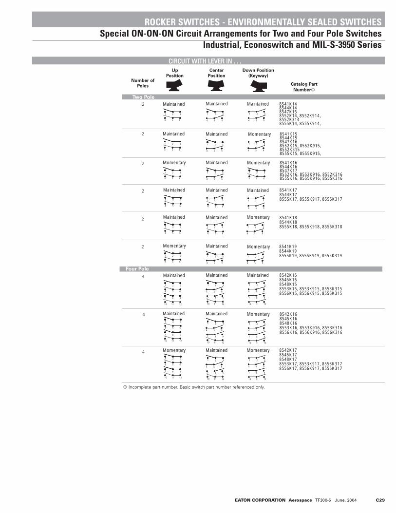
EATON CORPORATION Aerospace TF300-5 June, 2004 C29
CCIIRRCCUUIITT WWIITTHH LLEEVVEERR IINN .. .. ..
Two Pole
2
2
2
2
2
2
4
4
4
Number of
Poles Catalog Part
Number1
ROCKER SWITCHES - ENVIRONMENTALLY SEALED SWITCHESSpecial ON-ON-ON Circuit Arrangements for Two and Four Pole Switches
Industrial, Econoswitch and MIL-S-3950 Series
1 2 3
4 5 6
Maintained Maintained Maintained
1 2 3
4 5 6
Maintained
1 2 3
4 5 6
Momentary
1 2 3
4 5 6
Maintained
1 2 3
4 5 6
Maintained
1 2 3
4 5 6
Momentary
1 2 3
4 5 6
Maintained
Maintained
7 8 9
10 11 12
1 2 3
4 5 6
7 8 9
10 11 12
Momentary
1 2 3
4 5 6
7 8 9
10 11 12
1 2 3
654
Maintained
1 2 3
654
Maintained
Maintained
Maintained
Maintained
1 2 3
654
1 2 3
Maintained
7 8 9
10 11 12
654
1 2 3
Maintained
7 8 9
10 11 12
654
1 2 3
Maintained
7 8 9
10 11 12
654
1 2 3
654
Momentary
1 2 3
4 5 6
Momentary
321
4 5 6
321
4 5 6
1 2 3
654
1 2 3
654
Maintained
321
Momentary
1 2 3
654
Momentary
1 2 3
654
Maintained
1 2 3
654
7 8 9
121110
Momentary
1 2 3
654
7 8 9
121110
Momentary
1 2 3
654
7 8 9
121110
8541K148544K148547K158552K14, 8552K914, 8552K3148555K14, 8555K914,
8541K158544K158547K168552K15, 8552K915, 8552K3158555K15, 8555K915,
8541K168544K168547K178552K16, 8552K916, 8552K3168555K16, 8555K916, 8555K316
8541K178544K178555K17, 8555K917, 8555K317
8541K188544K188555K18, 8555K918, 8555K318
8541K198544K198555K19, 8555K919, 8555K319
8542K158545K158548K158553K15, 8553K915, 8553K3158556K15, 8556K915, 8556K315
8542K168545K168548K168553K16, 8553K916, 8553K3168556K16, 8556K916, 8556K316
8542K178545K178548K178553K17, 8553K917, 8553K3178556K17, 8556K917, 8556K317
654
Four Pole
Up
Position
Center
Position
Down Position
(Keyway)
1 Incomplete part number. Basic switch part number referenced only.

C30 EATON CORPORATION Aerospace TF300-5 June, 2004
CCIIRRCCUUIITT WWIITTHH LLEEVVEERR IINN .. .. ..
4
4
Number of
Poles
Catalog
Part
Number1
1 Incomplete part number. Basic switch part number referenced only.
Four Pole (Continued)
ROCKER SWITCHES - ENVIRONMENTALLY SEALED SWITCHESSpecial ON-ON-ON Circuit Arrangements for Two and Four Pole Switches Industrial, Econoswitch and MIL-S-3950 Series
4 5 6
1 2 3
4 5 6
1 2 3
4 5 6
1 2 3
10 11 12
7 8 9
10 11 12
7 8 9
10 11 12
7 8 9
Momentary
4 5 6
1 2 3
4 5 6
1 2 3
4 5 6
1 2 3
10 11 12
7 8 9
10 11 12
7 8 9
10 11 12
7 8 9
Maintained Momentary
8545K20
8545K21
Maintained Maintained Maintained
Up
Position
Center
Position
Down Position
(Keyway)

EATON CORPORATION Aerospace TF300-5 June, 2004 C31
No. of
Poles
Circuit
Poles
Connection Points Single Pole Double Pole
Down
Position
(Keyway)
1
2
Connect Common to Terminals
Connect Circuit "A" to Terminals
Connect Circuit "B" to Terminals
Connect Circuit "C" to Terminals
2
6
4
1
2 and 11
6 and 9
4 and 7
1 and 10
"Three Independent" ON-ON-ON Circuit DiagramFor switch modified with "Three Independent" ON-ON-ON Special Circuit.External Jumpers are required. User to connect wiring per instructions given below.
Circuit for Single Pole(Jumper between Terminals #3 & #5)
Circuit for Double Pole(Jumpers between Terminals #3 & #5
#8 & #12)
Note: Basic circuit same as offered with part numbers 8551K14, 8551K15 or 8551K16 for two pole devices and part numbers 8553K15, 8553K16 or 8553K17 for four pole devices.
Up
Position
No. of
Poles
Circuit Center
Maintained
Position
Down
Position
(Keyway)Circuit
Being Made
. . .
Terminal
Numbers
Making the
Circuit
2
4
Note: Requires two poles to achieve asingle pole device or four poles toachieve a double pole device.
Circuit for Single Pole (Jumper between terminals #2 & #4).Common terminal #5.Non-functional terminal #6
Circuit for Double Pole(Jumpers between terminals #2 & #4and #7 & #11).Common terminals #5 & #8.Non-functional terminals #6 & #9
1 3
4 5 6
1 3
4 5 6 4 5 6
1 3
1 3
4 5 6
1 3
4 5 6 4 5 6
7 9
10 11 12
7 97 9
10 11 12
7 9
(ON) (ON) (OFF)
(ON) (ON) (OFF)
7 97 9
2 2 2
2
8
10 11 1210 11 12
1 3
10 11 1210 11 12
8
2
8
2
8
UP(OFF)
CENTER (ON)
DOWN (ON)
UP(OFF)
CENTER (ON)
DOWN (ON)
#3 & #5
—
#3 & #5#8 & #12
—
#1 & #5
#1 & #5#8 & #10
Center
Maintained
Position
Up
Position
No. of
Poles
Circuit
Circuit
Being
Made . . .
Terminal
Numbers
Making the
Circuit
2
4
Note: Requires two poles to achievea single pole device or four poles toachieve a double pole device.
Circuit for Single Pole(Jumper between terminals #2 & #5).Common terminal #5.Non-functional terminal #1 & #4.
Circuit for Double Pole(Jumpers between terminals #2 & #5and #8 & #11).Common terminals #5 & #8.Non-functional terminals #1, #4,#7 & #10.
ROCKER SWITCHES - ENVIRONMENTALLY SEALED SWITCHESSpecial Circuit Arrangements for Two and Four Pole Switches
Industrial, Econoswitch and MIL-S-3950 Series
SSPPEECCIIAALL ""OONN--OONN--OONN"" CCIIRRCCUUIITT AARRRRAANNGGEEMMEENNTTSS
SSPPEECCIIAALL CCIIRRCCUUIITT ((OOFFFF 11-- OONN -- 22 OONN)) OOFFFF OONN OONN
SSPPEECCIIAALL PPRROOJJEECCTTOORR CCIIRRCCUUIITT ((OOFFFF -- 11 OONN -- 22 OONN)) OOFFFF OONN OONN
1 2 3
4 5 6
1 2 3
4 5 6 4 5 6
1 2 3
1 2 3
4 5 6
1 2 3
4 5 6 4 5 6
1 2 3
7 8 9
10 11 12
7 8 8
10 11 12
7 8 97 8 9
10 11 12
7 8 8
10 11 12
7 8 9
10 11 1210 11 12
Up
Position
Center
Maintained
Position
Down
Position
(Keyway)
1 3
4 5 6
1 3
4 5 6 4 5 6
1 3
1 3
4 5 6
1 3
4 5 6 4 5 6
7 9
10 11 12
7 97 9
10 11 12
7 9
(ON) (ON) (OFF)
(ON) (ON) (OFF)
7 97 9
2 2 2
2
8
10 11 1210 11 12 10 11 1210 11 12
8
2
8 8
UP(ON)
CENTER (ON)
DOWN (OFF)
UP(ON)
CENTER (ON)
DOWN (OFF)
#5 & #3
—
#3 & #5#11 & #12
1 32
#2 & #3#5 & #6
#5 & #3#5 & #6#8 & #12#8 & #9
—

C32 EATON CORPORATION Aerospace TF300-5 June, 2004
NOTES

EATON CORPORATION Aerospace TF300-5 June, 2004 D1
Basic Switches D2 - D4
• Ratings up to 40 amperes• One, two and three pole configurations• Choice of terminals• Maintained and momentary circuits• Snap action contact mechanism• Dry circuit capabilities
Roller and Leaf Actuator for Basic Switches D5
• Variety of actuator styles• Actuator metal parts are stainless passivated• All parts are treated for corrosion resistance• Adaptable to D and K series switches
Precision Snap Action Switches Index
SECTION D
*Most items listed in this catalog are standard products and are normally inDistributor Inventory; however, the current inventory status should be checked bycontacting your Eaton Customer Service Representative at 800-955-7354 or yourauthorized Distributor before placing orders.
Index D1

D2 EATON CORPORATION Aerospace TF300-5 June, 2004
SSEELLEECCTTIIOONN AANNDD SSPPEECCIIFFIICCAATTIIOONNSS TTAABBLLEE
Circuit Electrical Rating Life Terminals
Release
Force
(Min.)
Pretravel
(Max.)
Diff.
Travel
(Min.)
Diff.
Travel
(Min.)Description
Catalog
Number
Operating
Force
(Max.)
Characteristics
Series EF
Series G
Series E-4 & EM
4 CKTDbl. Brk.
1 PDT
1 PDT
2 CKT(1 PDT)Mom.
6 CKT3 N.O.3 N.C.
15 amps, 125/250VAC, 30VDC Resistive10 amps, 30VDC Inductive100,000 operations mechanical life50,000 operations electrical life
Operations, Min.150,000 2.5 amps. 125/250VAC Res. & Ind.100,000 5.0 amps. 125/250VAC Res. & Ind.50,000 4.0 amps. 30VDC Resistive50,000 2.5 amps. 30VDC Inductive
125/250VAC, 30 amps Resistive125/250VAC, 20 amps Inductive125/250VAC, 10 amps Motor28VDC, 40 amps Resistive28VDC, 30 amps Inductive28VDC, 15 amps Motor25,000 Operations Min.
15 amps, 125/250VAC, 60/400 Hz, 15 Amp Ind.,30VDC Resistive10 amps, 30VDC Inductive50,000 operations
25,000 operations min. electrical life at:4 amps, 28VDC Resistive2.5 amps, 28VDC Inductive
150,000 operations at 2.5 amps, 125/250VAC100,000 operations at 5.0 amps, 125/250VAC50,000 operations at 2.5 amps, 30VDC Inductive50,000 operations at 4.0 amps, 30VDC Resistive
150,000 operations at 2.5 amps, 125/250VAC100,000 operations at 5.0 amps, 125/250VAC50,000 operations at 2.5 amps, 30VDC Inductive50,000 operations at 4.0 amps, 30VDC Resistive
End SolderSide SolderSide SolderEnd SolderSide SolderSide Solder
Solder
DoubleTurret
SolderDoubleTurret
Wire Leads
Wire Leads
Solder
Side Solder
D4-4D8-4D8-9D4-44D8-44D8-344
E4-103
EM-4111
E4-270E4-271
EF-103
EF-110
G3-44
K3-4K3-12K3-44K3-344
Standard
Non-Simultaneous BreakMS25348-1MS25349-1Reset Type
Standard (Dust,Splash-proof)
MS25085-1MS25085-2
Standard
High-Temp. (-65°F to +300°F)
MS25357-1
StandardU.L. Listed - 30A, 250VACMS25356-1MS25353-1, Reset Type
28+/-5 oz
200grams
5-17 oz.
50.75 oz
56 oz.
5 oz.
3 oz.
40grams
4 oz.
6 oz.
4 oz.
1 oz.
.060 in.
.020 in.
.050 in.
0.093 in.
.060 in.
.075 in.
.003 in.
.004 in.
.055 +/-
.010 in.
.028 +/-.007 in.
.036 in.
.004 in.
.018 in.
.007 in.
.003 in.
.015 in.
.015 in.
.005 in
Series S
2 CKTDbl. Brk.
2 CKTDbl. Brk.
1 PNCDbl brk.1 PNODbl brk.
750,000 operations at 10 amps, 125VAC10,000 operations at 1 amp, 125VAC pilot duty200,000 operations at 10 amps, 30VDC res & ind
U.L. Listed for 10 amps, 125/250VAC,1/2 amp, 125VDC (1/2 hp, 125/250VAC)Military rated for 10 amps 125/250VAC, 30VDC Ind.
50,000 minimum operation125VAC, 10 amps Resistive & Inductive30VDC, 10 amps Resistive & Inductive125VAC, 6 amps motor28VDC, 6 amps motor
End SolderEnd ScrewSide Solder
S1-4S2-4S3-4
Standard
12+/-3 oz. 4 oz. .060 in..020+/-
.005in.015in
End SolderEnd Screw
S1-44S2-44
MS25342-1, .027 maxmove. diff.MS25344-1, .027 maxmove. diff.
1.25 lbs
12 +/-3 oz4 oz. .060 in.
0.027
750,000 operations at 10 amps, 125VAC10,000,000 oper. at 1 amp, 125VAC pilot duty200,000 operations at 10 amps, 30VDC InductiveMilitary rated for 10 amps 125/250VAC, 30VDC
Side SolderEnd ScrewSide SolderSide Solder
S3-44S2-25S3-5S3-6
MS25343-1, .020+/- .005 move diff
Standard .020 +/- .005 move. diff.
Standard .010 +/- .004-.003 mv df
U.L. Listed
19 oz.15 oz.15 oz.15 oz.
+/-.020in
.015 in.
Series K
BASIC SWITCHESPrecision Snap Action Switches
FFEEAATTUURREESS
• Snap action• Plastic, flame resistant case• Single, double and three pole circuits• Eight types of terminations• Long life• 1000 V rms dielectric strength• Current capacities from dry circuit to 40 amperes
• Military approved• Environmentally sealed• UL recognized• Low movement differential and operating force types available• Stacking and gang mounting capabilities
SSEERRIIEESS
Series D

EATON CORPORATION Aerospace TF300-5 June, 2004 D3
SSeerriieess GG SSeerriieess EEFF
Dimensions for reference only.
STANDARD0.00 = inches
[0,0] = mm
.500[12,70]
.535[13,59]
.031[0,79]
.296[7,52]
.120[3,05].515
[13,08]
.218[5,54]
.114[2,90]
.125[3,18]
.114[2,90]
1.250[31.75
.093[2,36]
(8) HOLES
.187[4,75]
.125[3,18] 1.687
[42,85] .218[5,54]
.250[6,35]
.125
[3,1
8]
.437
[11,
10]
.890
[22,
61]
PRETRAVELOPER POINT
.505
[12,
83]
DIA. HOLE
DIA.DIA.
DIA. DIA.
DIA.
SIDESOLDER
ENDSOLDER
MAX.
MAX.
DIA.
RESET MODEL ONLY
1
4
2
5
3
8
6
7
.094[2,39]
.098[2,49]
.375[9,53].088
[2,24]
.094[2,39]
MTG. HOLE DETAIL
.218[5,54]
.440
[11,
18]
.088[2,24]
.187[4,75]
.058[1,47]
(3) HOLES.297
[7,54].297
[7,54]COM
NO
NC
.330
[8,3
8]
.297[7,54]
.781[19,84]
PRETRAVEL
OPER. POINT
.109[2,77]
SOLDER
.125[3,18]
DOUBLE TURRET
DIA.
DIA.
DIA.
DIA.
OPEN END OFWIRESLOT REVERSEON BOTTOMTERMINALS
1.750[44,45]
.875[22,23] .219
[5,58]
.234[5,94]
.105[2,67]
.1604,08]
.250[6,35]
.094[2,39] .562
[14,27]
.141[3,58]
.672[17,07]
.547
[13,
89]
.360
[9,4
1]
.114[2,90] DIA
(2)MTG.HOLES
NONC
NONC
PRETRAVEL
OPER POINT
.375[9.53]
.158[3,98]
.875[22,23]
.344
[8,7
4]
.297[7,64]
.250[6,35]
.096[2,44]
.088[2,24]
.375[9,53]
DIA..088[2,24]HOLE
PRETRAVEL
.425
[10,
80]
OPER
.PO
INT
.359
[9,1
2]
C. N.O. N.C.
.078[1,88]
CORROSIONRESISTANTSTEEL PLUNGER
EPOXYCASTINGRESIN
(3) 320 GA. WIRELEADS PERMIL-W-5086
.344
[8,7
4]
.594
[15,
09]
WIRE LEADS
12" +/- 0.250"
BASIC SWITCHESPrecision Snap Action Switches
AAPPPPRROOXXIIMMAATTEE DDIIMMEENNSSIIOONNSSTerminal Styles (Other terminations available)
SSeerriieess DD SSeerriieess EE44 aanndd EEMM

D4 EATON CORPORATION Aerospace TF300-5 June, 2004
Dimensions for reference only.
STANDARD0.00 = inches
[0,0] = mm
.500
[12,
70]
.250[6,35]
PRETRAVEL
SIDESOLDER
S3
END SCREW
S2
END S OLDER
S1
OTHER TERMINA TIONS A VAI LABLE
.218[5,54]
.075[1,91]
.101[2,57]
MTG HOLES
.140[3,58]
OPER POINT
.093[2,38]
.312
[7,9
2]
.120[3,05]
.520[13,21]
.168[4,27]
.640
[16,
28]
.515
[13,
08]
RESET MODEL ONLY
OPER POINT
.296[7,52]
.620
[15,
75]
.515[13,08]
.093[2,36]
(4) HOLES
.250[6,35]
.187[4,75]
.125[3,18]
1.887[42,85]1.265[32,13]
.114[2,90]
(2)HOLES.500
[12,70]
.543
7[1
1,10
]
.505
[12,
83]
OPER
.PT
.
.535
[13,
59]
RESE
TPT
.
.543
7[1
1,10
]
X .103[2,62]
(12)HOLES
.859[21,82]
1.265[32,13]
.125[3,18]
.187[4,75]
.218[5,54]
.1.3
27[3
3,71
] 1.50
0[3
8,10
]
.125[3,18]
.031[0,79]
.120[3,05]
RESET MODELONLY
.296[7,52]
DIA.
DIA.
DIA.
MAX.
DIA.
DIA.
BASIC SWITCHESPrecision Snap Action Switches
AAPPPPRROOXXIIMMAATTEE DDIIMMEENNSSIIOONNSSTerminal Styles (Other terminations available)
SSeerriieess SS SSeerriieess KK

EATON CORPORATION Aerospace TF300-5 June, 2004 D5
Roller Lever
Type A2-5
Actuator A2-5
Shown with
Basic Switch K3-4
Circuit Electrical Rating Life
Release
Force
(Min.)
Pretravel
(Max.)
Diff.
Travel
Over
TravelCatalog
Number
Operating
Force
(Max.)
Characteristics
3 PDT6 CKTMomentary
Can be used with "D" or "K" series basic switch shown on pg D2. A2-5/K3-4 14 oz. 1 oz. .240 in. 112 +/-.028in.
.060in.
2 PDT4 CKTMomentary
Can be used with "D" or "K" series basic switch shown on pg D2. A5-18/D8-4 16 +/-4 oz.
.375 in +/-.066 in.
.156in.
.156 in.
Extended Leaf
Type A5-18
Actuator A5-18
Shown with
Basic Switch D8-4
.375[9,53]
1.500[38,10]
.281[7,14]
.125[3,18]
.500[12,70]
1.031[26,19]
.116[2,95]
1.18
7[3
0,15
]
OVERTRAVEL
MOVEMENTDIFFERENTIAL
PRETRAVEL
.265[6,73]
.609
[15,
47]
1.04
7[2
6,59
]
.060[1,52]DIA.
.125[3,18]
.218[5,54]
.020[0,51]
.250[6,35]
.093[2,36]
.025[0,64]
.116[14,68]
.453[11,51]
.969[24,61]
.844[21,44]
.500[12,70]
.344[8,74]
.578
[14,
68]
.920
[23,
37]
DIA.
DIA.
Catalog Number of Actuator
Basic Switch Complete Part Number
BASIC SWITCHESPrecision Snap Action Switch
Roller and Leaf Actuator
FFEEAATTUURREESS
• All parts treated for corrosion resistance• Actuator metal parts are stainless passivated• Operating characteristics depend on switch selected• Catalog numbers which appear with a slash between actuator and basic switch
part number are screw type assemblies and can be supplied as separate com-ponents
WWHHEENN OORRDDEERRIINNGG SSPPEECCIIFFYY .. .. .. • Catalog number of actuator plus part number of basic switch.
Order Example:A2-5 / K3-4 = A2-5/K3-4
SSEELLEECCTTIIOONN AANNDD SSPPEECCIIFFIICCAATTIIOONNSS TTAABBLLEETTYYPPEE
AAPPPPRROOXXIIMMAATTEE DDIIMMEENNSSIIOONNSS
A2-5 A5-18

D6 EATON CORPORATION Aerospace TF300-5 June, 2004
NOTES
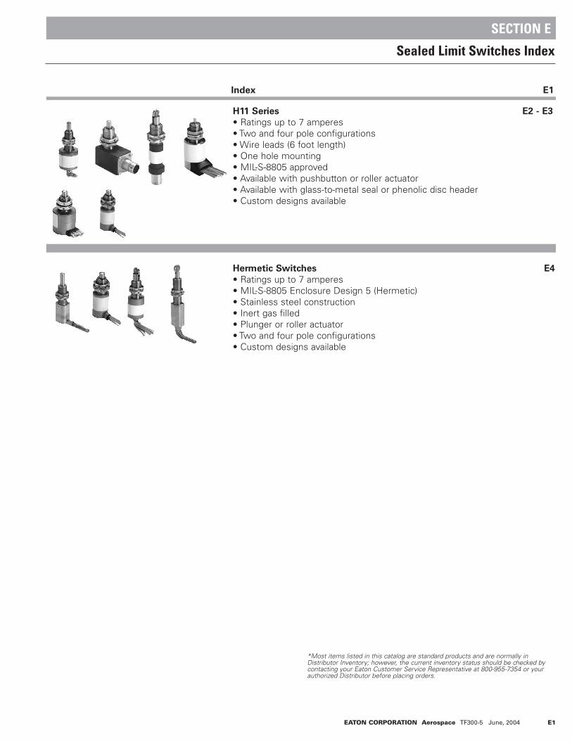
EATON CORPORATION Aerospace TF300-5 June, 2004 E1
H11 Series E2 - E3
• Ratings up to 7 amperes• Two and four pole configurations• Wire leads (6 foot length)• One hole mounting• MIL-S-8805 approved• Available with pushbutton or roller actuator• Available with glass-to-metal seal or phenolic disc header• Custom designs available
Hermetic Switches E4
• Ratings up to 7 amperes• MIL-S-8805 Enclosure Design 5 (Hermetic)• Stainless steel construction• Inert gas filled• Plunger or roller actuator• Two and four pole configurations• Custom designs available
Sealed Limit Switches Index
SECTION E
*Most items listed in this catalog are standard products and are normally inDistributor Inventory; however, the current inventory status should be checked bycontacting your Eaton Customer Service Representative at 800-955-7354 or yourauthorized Distributor before placing orders.
Index E1

E2 EATON CORPORATION Aerospace TF300-5 June, 2004
Poles and
Throw ActuatorOp.
Force
Characteristics
2 PDT
4 PDT
2 PDT
2 PDT
4 PDT
2 PDT
4 PDT
Plunger
Plunger
Plunger
Plunger
Plunger
RollerPlunger
RollerPlunger
6-12 lbs.
6-12 lbs.
6-12 lbs.
6-12 lbs.
6-12 lbs.
6-12 lbs.
6-12 lbs.
4 lbs. min.
4 lbs. min.
4 lbs. min.
4 lbs. min.
4 lbs. min.
4 lbs. min.
4 lbs. min
.040 in. max.
.040 in. max.
.070 in. min.
.040 in. max.
.040 in. max.
.040 in. min.
.040 in. max.
.250 in. min.
.250 in. min.
.250 in. max.
.125 in. min.
.125 in. min.
.125 in. min.
.125 in. min.
.020 in. max.
.020 in. max.
.020 in. max.
.020 in. max.
.020 in. max.
.020 in. max.
.020 in. max.
MS21321-1(8805/39)
MS21321-2(8805/39)
MS24331-1(8805/40)
MS27240-1(8805/43)
MS27240-2(8805/43)
MS27240-3(8805/43)
MS27240-4(8805/43)
H11-335
H11-395
H11-375
H11-330
H11-390
H11-331
H11-391
7.2
12.5
7.3
8
13.6
8
13.6
.980
1.20
.980
1.0
1.20
1.0
1.20
.720
1.03
1.015
.720
1.03
.720
1.03
.625-24
.625-24
.625-24
.469-32
.469-32
.32
.469-32
Return
Force
Diff.
Travel
MS Part
Number
Catalog
Number
Weight
(oz.)
Height
“A” Dim.
Housing
Dimensions Inches
Standard Base
Diameter
“B” Dim.
Bushing
Thread
Size
Pre-
Travel
Over-
Travel
Cat. No. H11-375 Cat. No. H11-330 Cat. No. H11-395 Cat. No. H11-390 Cat. No. H11-335 Cat. No. H11-331
STANDARD SWITCH SERIES
LIMIT SWITCHESSeries - H11 Environmentally Sealed Switches
Altitude Inrush Resistive Motor Inductive
Sea Level 24 7 4 4
50,000 Feet 24 7 4 2.5
100,000 Feet 24 7 4 1.5
Amperes - 28VDC
SSEELLEECCTTIIOONN TTAABBLLEE -- AAllll sswwiittcchheess sshhoowwnn hhaavvee 66--ffoooott lleennggtthh lleeaadd wwiirree ppeerr MMIILL--WW--2222775599//77 mmaarrkkeedd ppeerr MMIILL--WW--55008888..
CCUURRRREENNTT RRAATTIINNGGSSFFEEAATTUURREESS
• Current ratings up to 7 amperes• Two and four pole configurations• Wire leads with strain relief• Connector option available• Single hole mounting• Ice scraping capability• Simultaneous contact circuitry• Reliable lifetime operation• Durable construction for harsh
environment applications• Wiring schematic located on switch
body• Customized to fit your exact
application
SSPPEECCIIFFIICCAATTIIOONNSS
• MIL-S-8805 approved• Enclosure per MIL-S-8805 Design 4
(Resilient)• Wire leads per MIL-W-22759/7• Operating temperature range:
-65°F to +185°F (-55°C to + 85°C)
• Electrical life: 25,000 cycles at rated load• Mechanical life: 25,000 cycles• All metal parts treated for corrosion
resistance

EATON CORPORATION Aerospace TF300-5 June, 2004 E3
Plunger Operated - As with all push-on units, this actuator has an ice scraper for clearing the plunger of ice and debris with each operation.
Roller Plunger - For cam and slide actuation. Roller adjusts radially in 45° increments. Cam differential should not exceed 0.125 in., and cam slope should not exceed 30° .
Dimensions for reference only.
STANDARD0.00 = inches
[0,0] = mm
Plunger
.250[6,35]
.625
[15,
88]
.875
[22,
22]
.469-32 UNS THREAD
DIA.
2 P.D.T.
1
2
35
64
1
2
35
64
8
97
11
1210
.625[15,88]
.375[9,53]
.469- 32 UNS THREAD
Roller Plunger
Plunger
120W120W
ROLLER
1.29
5[3
2,89
]
.638
[16,
21]
.434
[11,
02]
DIA.
.6 [15[2
X
WIRE LEADSMARKED PERMIL-W-5088
EPOXY POTTINGAROUND TERMINALS
STANDARD GLASSTO METAL —
HEADER PLATE
SOLDEREDJOINTS
BASICSWITCHES
(STANDARDSERIES)
STAINLESSSTEEL
BUSHING& HOUSING
ICE SCRAPERRING
STAINLESSSTEEL
PLUNGER/ACTUATOR
O-RING SEAL
MIL LISTEDMOUNTED
HARDWARE
WELD JOINTS
INERT GASFILLED
SWITCHINGCHAMBER
LIMIT SWITCHESSeries - H11 Environmentally Sealed Switches
SSTTAANNDDAARRDD AACCTTUUAATTOORR
SSCCHHEEMMAATTIICC
BBAASSIICC CCOONNSSTTRRUUCCTTIIOONN
SSTTAANNDDAARRDD AACCTTUUAATTOORR

E4 EATON CORPORATION Aerospace TF300-5 June, 2004
TWO POLE MINIATURE
P/N DESCRIPTION
HH-630A Plunger Side ExitHH-630B Plunger Rear ExitHH-631A Roller Side ExitHH-631B Roller Rear Exit
12
453
6
.25[6,4]
.625[15,9]
.250[6,4]
.375[9,5]
1.295[32,9]
(NON-ADJUSTABLE).469-32UNS-2A
.875
[22,
2]FR
EE P
OSIT
ION
1.18
[29,
9]
.270[6,8]
.72[18,3]
DIA.MAX.DIA.
DIA.DIA. X .120
[3,2]SST ROLLER
TYP
(REF)
FREE POSITION
FOUR POLE SERIES
P/N DESCRIPTION
HH-695A Plunger Side ExitHH-695B Plunger Rear ExitHH-696A Roller Side ExitHH-696B Roller Rear Exit
12
453
786
10119
12
.25[6,4]
1.00[25,4]
.25[6,4]
.50[12,7]
1.78[45,2]
(NON-ADJUSTABLE).625-24UNEF-2A
.1.3
75[3
4,9]
FREE
POS
ITIO
N
1.33
[33,
8]
.375[9,5]
1.031[26,2]
DIA. MAX.
MAX
.
DIA.
(REF)
DIA.DIA. X .125
[3,2]SST ROLLER
TYP
FREE POSITION
MS35333 TYPELOCK WASHER
MS21340 TYPE NUT(2)
MS25081 TYPEKEYWASHER
72[1828,8]
METAL BELLOWSINERT GAS FILLED SWITCH CHAMBER SEALED TO1X10-8 ATM CC/SEC.
POTTING
WIRE PER MIL-W-81381 TYPEMARKED AT 6.00 SPACING(TYP)
GLASS/METALHEADER PLATE
M8805/4 SWITCH TYPE
STAINLESS STEELBUSHING & HOUSING
AL ICE SCRAPERG & O-RING SEAL
TAINLESS STEELNGER/ACTUATOR
TYP.
.375[9,5]
.250[6,4]
TYP.
TYP
Dimensions for reference only.
STANDARD0.00 = inches
[0,0] = mm
LIMIT SWITCHESSeries - HH Hermetically Sealed Switches
HHEERRMMEETTIICCAALLLLYY SSEEAALLEEDD LLIIMMIITT SSWWIITTCCHHEESS
TTYYPPIICCAALL CCOONNSSTTRRUUCCTTIIOONN -- RREEAARR EEXXIITT DDEESSIIGGNN
CCUURRRREENNTT RRAATTIINNGGSSFFEEAATTUURREESS && SSPPEECCIIFFIICCAATTIIOONNSS
• Meets MIL-S-8805 Enclosure Design 5 (Hermetic)
• Mechanical life: 25,000 cycles• Electrical life: 25,000 cycles• Operating temperature:
-65°F to +185°F (-55°C to +85°C)
• Leak rate less than 1 x 10⁻⁸
• Rugged stainless steel construction• Inert gas filled
OOPPTTIIOONNSS
• Low level circuitry capability• Rear or side exit connector• RFI/EMI shielded cable• High temperature operation• Ball bearing plunger• Custom bushing and plunger sizes• Roller plunger available in 45° increments• Special purpose designs
HARDWARE SUPPLIEDUNASSEMBLED
Amperes - 28VDC
Resistive Inductive Motor
Sea Level50,000 feetLow Level Rating
7.07.00.1
4.02.50.1
4.04.0—
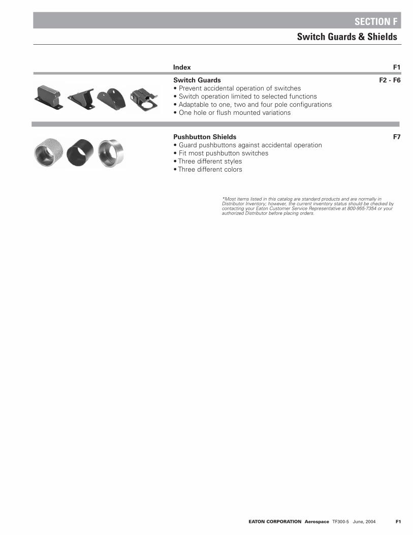
EATON CORPORATION Aerospace TF300-5 June, 2004 F1
Switch Guards F2 - F6
• Prevent accidental operation of switches• Switch operation limited to selected functions• Adaptable to one, two and four pole configurations• One hole or flush mounted variations
Pushbutton Shields F7
• Guard pushbuttons against accidental operation• Fit most pushbutton switches• Three different styles• Three different colors
Switch Guards & Shields
SECTION F
*Most items listed in this catalog are standard products and are normally inDistributor Inventory; however, the current inventory status should be checked bycontacting your Eaton Customer Service Representative at 800-955-7354 or yourauthorized Distributor before placing orders.
Index F1

F2 EATON CORPORATION Aerospace TF300-5 June, 2004
Code 1 Code 2, 3, 16, 17 Code 7, 8, 10-14 Code 9
Code 4, 5 Code 18-25 Code 26-29 Code 15
Code 6
SSEELLEECCTTIIOONN TTAABBLLEE
SWITCH GUARDS & SHIELDSSwitch Guards MIL-G-7703 and Industrial Grade
• For use with 2 or 3 position switches• Lever covers molded in various colors• Cover closure transfers toggle lever. See
code number for details.• Metal and molded covers• Flush and One Hole Mounted (OHM) mount-
ing styles• MS approved and QPL'd per MIL-G-7703• Covers are molded out of Thermoset molding
materials
• Guard covers are spring loaded to either close or lock in open position
• One hole mounting and three hole mounting available
• Keyway orientation variations offered on some guards
FFEEAATTUURREESS
1 Flush 3 Phenolic Red — — — MS25223-1 8496K11
2 Flush 2 Phenolic Red — — — MS25224-2 8497K23 Flush 3 Phenolic Red — — — MS25225-2 8499K24 Flush 2 Metal Green — — — MS25452-1 8498K25 Flush 2 Metal Green EMERGENCY — NAF47851-1 K2
6 Flush/OHM 2 or 3 Metal3
Black — — — MS25221-1 8495K17 OHM 3 Phenolic Red — — Opp. Hinged End MS25214-2 8494K28 OHM 3 Phenolic Red — — Hinged End MS25214-3 K39 OHM 3 Phenolic Red — — Opp. Hinged End MS25223-2 8496K210 OHM 2 Phenolic Red — — Opp. Hinged End MS25224-1 8497K111 2 Phenolic Red — — Hinged End MS25224-3 8497K312 2 Phenolic Red ON OFF Opp. Hinged End — K713 OHM 3 Phenolic Red — — Opp. Hinged End MS25225-1 8498K114 3 Phenolic Red — — Hinged End MS25225-3 K3
15 2 or 3 Metal3
Black — — Opp. Pin Hole MS24417-1 8492K116 2 or 3 Phenolic Red — — Opp. Hinged End MS27752-1 8498K617 Flush 3 Phenolic Red — — — MS25214-1 8494K118 3 Red — — Hinged End 8493K419 3 Red — — Opp. Hinged End K520 OHM 2 Metal Red — — Hinged End K621 2 Red — — Opp. Hinged End K722 3 Black — — Hinged End K823 3 Black — — Opp. Hinged End 8493K924 2 Black — — Hinged End K1025 OHM 2 Metal Black — — Opp. Hinged End K1126 3 Red — — Right Side K1227 3 Red — — Left Side K1328 OHM 3 Metal Black — — Right Side K1429 3 Black — — Left Side K15
1 Will not return lever when mounting plate is over .0625 [1,58] thick.2
Custom lettering or symbols available.3
Guard has no moving lever.4
Optional colors: black phenolic available for 8497. Where other colors are required, they are sprayed over standard color.
Switch
Guard
Code
Number
Marking 2
Switch
Mounting
Switch
Positions
Lever
Material Color 4
Hinged
End
Other
End
Location of
Keyway Tab
Military
Part
Number
Catalog
Number

EATON CORPORATION Aerospace TF300-5 June, 2004 F3
Code 1 and 9
• For three-position switches• Returns lever to center position from either extreme• Guard housing is spring loaded to retain closed position
Code 2, 10, 11 and 12
• For full throw single throw switches• Returns lever to OFF position
Code 3, 13 and 14
• For three-position switches• Returns lever from up position to center position• Will not change toggle position when it is in down position
Code 4 and 5
• For two-position full throw switches• Permits locking toggle in extreme up position
Code 6 and 15
• Insertion of pin through guard prevents accidental operation• Prevents transfer of single throw switches• Permits operation from first position to center on three-posi-
tion switches
Code 17
• For three-position flush mount switches• Guard lever remains fixed in open or closed position• Return lever to center position from either extreme
Code 7 and 8
• For three-position switches• Returns lever to center position from either extreme• Guard housing remains fixed in open and closed position
Code 16
• For two- or three-position switches• Closing guard does not affect toggle position
Code 18, 19, 22 and 23
• For three-position switches• Returns lever from up position to center position• Will not change toggle position when it is in down position
Code 20, 21, 24 and 25
• For two-position full throw switches• Returns lever from up position to down position
Code 26-29
• For three-position switches• With both guards in closed position, switch toggle lever is
locked in center position. With one guard each in open and closed position, switch can be toggled between center and open guard position; with both guards in open position, switchcan be toggled between left, center, and right position.
SWITCH GUARDS & SHIELDSSwitch Guards MIL-G-7703 and Industrial Grade
SSPPEECCIIFFIICCAATTIIOONNSS
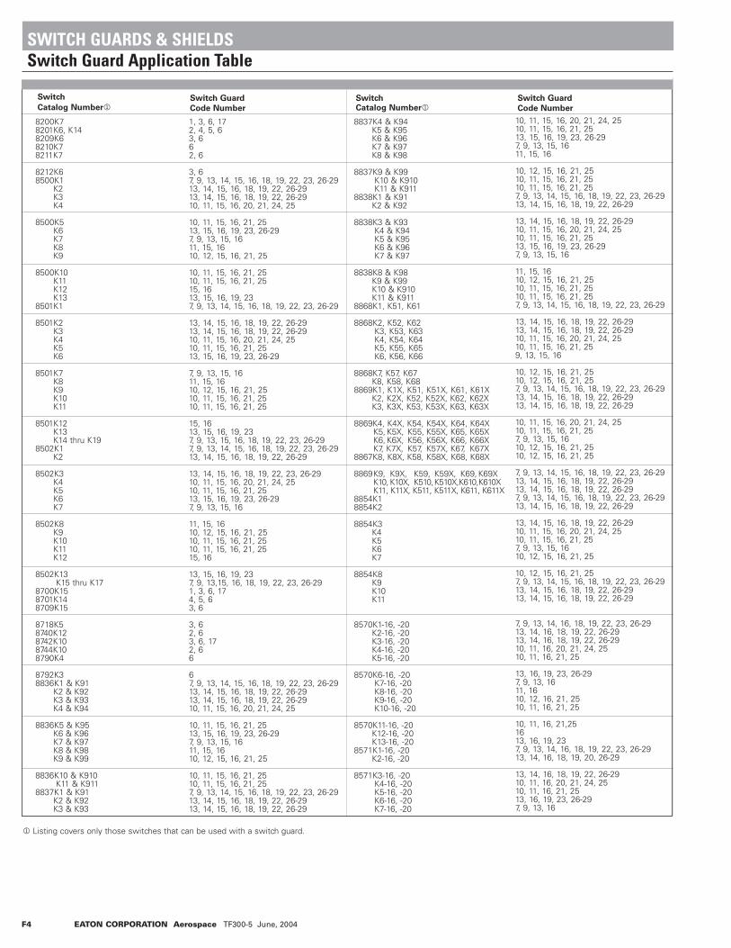
F4 EATON CORPORATION Aerospace TF300-5 June, 2004
Switch
Catalog Number1Switch Guard
Code Number
SwitchCatalog Number1
8200K78201K6, K148209K68210K78211K7
8212K68500K1
K2K3K4
8500K5K6K7K8K9
8500K10K11K12K13
8501K1
8501K2K3K4K5K6
8501K7K8K9K10K11
8501K12K13K14 thru K19
8502K1K2
8502K3K4K5K6K7
8502K8K9K10K11K12
8502K13K15 thru K17
8700K158701K148709K15
8718K58740K128742K108744K108790K4
8792K38836K1 & K91
K2 & K92K3 & K93K4 & K94
8836K5 & K95K6 & K96K7 & K97K8 & K98K9 & K99
8836K10 & K910K11 & K911
8837K1 & K91K2 & K92K3 & K93
1, 3, 6, 172, 4, 5, 63, 662, 6
3, 67, 9, 13, 14, 15, 16, 18, 19, 22, 23, 26-2913, 14, 15, 16, 18, 19, 22, 26-2913, 14, 15, 16, 18, 19, 22, 26-2910, 11, 15, 16, 20, 21, 24, 25
10, 11, 15, 16, 21, 2513, 15, 16, 19, 23, 26-297, 9, 13, 15, 1611, 15, 1610, 12, 15, 16, 21, 25
10, 11, 15, 16, 21, 2510, 11, 15, 16, 21, 2515, 1613, 15, 16, 19, 237, 9, 13, 14, 15, 16, 18, 19, 22, 23, 26-29
13, 14, 15, 16, 18, 19, 22, 26-2913, 14, 15, 16, 18, 19, 22, 26-2910, 11, 15, 16, 20, 21, 24, 2510, 11, 15, 16, 21, 2513, 15, 16, 19, 23, 26-29
7, 9, 13, 15, 1611, 15, 1610, 12, 15, 16, 21, 2510, 11, 15, 16, 21, 2510, 11, 15, 16, 21, 25
15, 1613, 15, 16, 19, 237, 9, 13, 15, 16, 18, 19, 22, 23, 26-297, 9, 13, 14, 15, 16, 18, 19, 22, 23, 26-2913, 14, 15, 16, 18, 19, 22, 26-29
13, 14, 15, 16, 18, 19, 22, 23, 26-2910, 11, 15, 16, 20, 21, 24, 2510, 11, 15, 16, 21, 2513, 15, 16, 19, 23, 26-297, 9, 13, 15, 16
11, 15, 1610, 12, 15, 16, 21, 2510, 11, 15, 16, 21, 2510, 11, 15, 16, 21, 2515, 16
13, 15, 16, 19, 237, 9, 13,15, 16, 18, 19, 22, 23, 26-291, 3, 6, 174, 5, 63, 6
3, 62, 63, 6, 172, 66
67, 9, 13, 14, 15, 16, 18, 19, 22, 23, 26-2913, 14, 15, 16, 18, 19, 22, 26-2913, 14, 15, 16, 18, 19, 22, 26-2910, 11, 15, 16, 20, 21, 24, 25
10, 11, 15, 16, 21, 2513, 15, 16, 19, 23, 26-297, 9, 13, 15, 1611, 15, 1610, 12, 15, 16, 21, 25
10, 11, 15, 16, 21, 2510, 11, 15, 16, 21, 257, 9, 13, 14, 15, 16, 18, 19, 22, 23, 26-2913, 14, 15, 16, 18, 19, 22, 26-2913, 14, 15, 16, 18, 19, 22, 26-29
8837K4 & K94K5 & K95K6 & K96K7 & K97K8 & K98
8837K9 & K99K10 & K910K11 & K911
8838K1 & K91K2 & K92
8838K3 & K93K4 & K94K5 & K95K6 & K96K7 & K97
8838K8 & K98K9 & K99K10 & K910K11 & K911
8868K1, K51, K61
8868K2, K52, K62K3, K53, K63K4, K54, K64K5, K55, K65K6, K56, K66
8868K7, K57, K67K8, K58, K68
8869K1, K1X, K51, K51X, K61, K61XK2, K2X, K52, K52X, K62, K62XK3, K3X, K53, K53X, K63, K63X
8869K4, K4X, K54, K54X, K64, K64XK5, K5X, K55, K55X, K65, K65XK6, K6X, K56, K56X, K66, K66XK7, K7X, K57, K57X, K67, K67X
8867K8, K8X, K58, K58X, K68, K68X
8869K9, K9X, K59, K59X, K69, K69XK10, K10X, K510,K510X,K610,K610XK11, K11X, K511, K511X, K611, K611X
8854K18854K2
8854K3K4K5K6K7
8854K8K9K10K11
8570K1-16, -20K2-16, -20K3-16, -20K4-16, -20K5-16, -20
8570K6-16, -20K7-16, -20K8-16, -20K9-16, -20K10-16, -20
8570K11-16, -20K12-16, -20K13-16, -20
8571K1-16, -20K2-16, -20
8571K3-16, -20K4-16, -20K5-16, -20K6-16, -20K7-16, -20
10, 11, 15, 16, 20, 21, 24, 2510, 11, 15, 16, 21, 2513, 15, 16, 19, 23, 26-297, 9, 13, 15, 1611, 15, 16
10, 12, 15, 16, 21, 2510, 11, 15, 16, 21, 2510, 11, 15, 16, 21, 257, 9, 13, 14, 15, 16, 18, 19, 22, 23, 26-2913, 14, 15, 16, 18, 19, 22, 26-29
13, 14, 15, 16, 18, 19, 22, 26-2910, 11, 15, 16, 20, 21, 24, 2510, 11, 15, 16, 21, 2513, 15, 16, 19, 23, 26-297, 9, 13, 15, 16
11, 15, 1610, 12, 15, 16, 21, 2510, 11, 15, 16, 21, 2510, 11, 15, 16, 21, 257, 9, 13, 14, 15, 16, 18, 19, 22, 23, 26-29
13, 14, 15, 16, 18, 19, 22, 26-2913, 14, 15, 16, 18, 19, 22, 26-2910, 11, 15, 16, 20, 21, 24, 2510, 11, 15, 16, 21, 259, 13, 15, 16
10, 12, 15, 16, 21, 2510, 12, 15, 16, 21, 257, 9, 13, 14, 15, 16, 18, 19, 22, 23, 26-2913, 14, 15, 16, 18, 19, 22, 26-2913, 14, 15, 16, 18, 19, 22, 26-29
10, 11, 15, 16, 20, 21, 24, 2510, 11, 15, 16, 21, 257, 9, 13, 15, 1610, 12, 15, 16, 21, 2510, 12, 15, 16, 21, 25
7, 9, 13, 14, 15, 16, 18, 19, 22, 23, 26-2913, 14, 15, 16, 18, 19, 22, 26-2913, 14, 15, 16, 18, 19, 22, 26-297, 9, 13, 14, 15, 16, 18, 19, 22, 23, 26-2913, 14, 15, 16, 18, 19, 22, 26-29
13, 14, 15, 16, 18, 19, 22, 26-2910, 11, 15, 16, 20, 21, 24, 2510, 11, 15, 16, 21, 257, 9, 13, 15, 1610, 12, 15, 16, 21, 25
10, 12, 15, 16, 21, 257, 9, 13, 14, 15, 16, 18, 19, 22, 23, 26-2913, 14, 15, 16, 18, 19, 22, 26-2913, 14, 15, 16, 18, 19, 22, 26-29
7, 9, 13, 14, 16, 18, 19, 22, 23, 26-2913, 14, 16, 18, 19, 22, 26-2913, 14, 16, 18, 19, 22, 26-2910, 11, 16, 20, 21, 24, 2510, 11, 16, 21, 25
13, 16, 19, 23, 26-297, 9, 13, 1611, 1610, 12, 16, 21, 2510, 11, 16, 21, 25
10, 11, 16, 21,251613, 16, 19, 237, 9, 13, 14, 16, 18, 19, 22, 23, 26-2913, 14, 16, 18, 19, 20, 26-29
13, 14, 16, 18, 19, 22, 26-2910, 11, 16, 20, 21, 24, 2510, 11, 16, 21, 2513, 16, 19, 23, 26-297, 9, 13, 16
Switch Guard
Code Number
1 Listing covers only those switches that can be used with a switch guard.
SWITCH GUARDS & SHIELDSSwitch Guard Application Table
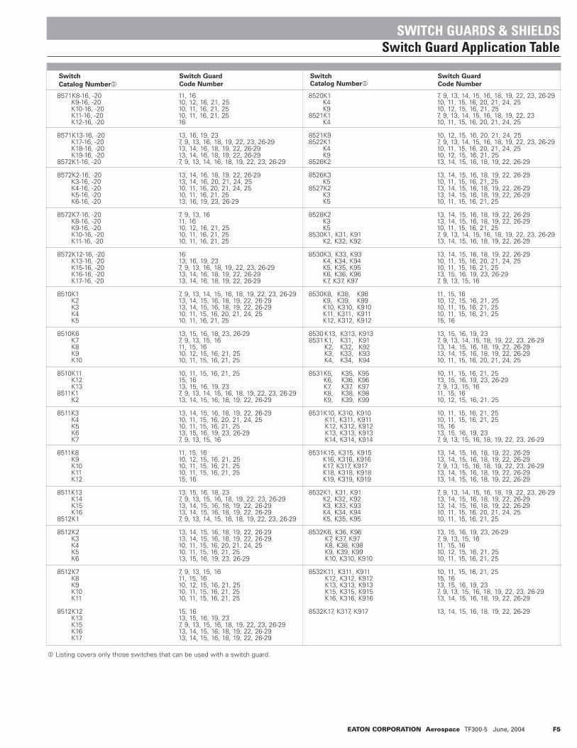
EATON CORPORATION Aerospace TF300-5 June, 2004 F5
Switch
Catalog Number1Switch Guard
Code Number
SwitchCatalog Number1
8571K8-16, -20K9-16, -20K10-16, -20K11-16, -20K12-16, -20
8571K13-16, -20K17-16, -20K18-16, -20K19-16, -20
8572K1-16, -20
8572K2-16, -20K3-16, -20K4-16, -20K5-16, -20K6-16, -20
8572K7-16, -20K8-16, -20K9-16, -20K10-16, -20K11-16, -20
8572K12-16, -20K13-16, -20K15-16, -20K16-16, -20K17-16, -20
8510K1K2K3K4K5
8510K6K7K8K9K10
8510K11K12 K13
8511K1K2
8511K3K4K5K6K7
8511K8K9K10K11K12
8511K13K14K15K16
8512K1
8512K2K3K4K5K6
8512K7K8K9K10K11
8512K12K13K15K16K17
11, 1610, 12, 16, 21, 2510, 11, 16, 21, 2510, 11, 16, 21, 2516
13, 16, 19, 237, 9, 13, 16, 18, 19, 22, 23, 26-2913, 14, 16, 18, 19, 22, 26-2913, 14, 16, 18, 19, 22, 26-297, 9, 13, 14, 16, 18, 19, 22, 23, 26-29
13, 14, 16, 18, 19, 22, 26-2913, 14, 16, 20, 21, 24, 2510, 11, 16, 20, 21, 24, 2510, 11, 16, 21, 2513, 16, 19, 23, 26-29
7, 9, 13, 1611, 1610, 12, 16, 21, 2510, 11, 16, 21, 2510, 11, 16, 21, 25
1613, 16, 19, 237, 9, 13, 16, 18, 19, 22, 23, 26-2913, 14, 16, 18, 19, 22, 26-2913, 14, 16, 18, 19, 22, 26-29
7, 9, 13, 14, 15, 16, 18, 19, 22, 23, 26-2913, 14, 15, 16, 18, 19, 22, 26-2913, 14, 15, 16, 18, 19, 22, 26-2910, 11, 15, 16, 20, 21, 24, 2510, 11, 16, 21, 25
13, 15, 16, 18, 23, 26-297, 9, 13, 15, 1611, 15, 1610, 12, 15, 16, 21, 2510, 11, 15, 16, 21, 25
10, 11, 15, 16, 21, 2515, 1613, 15, 16, 19, 237, 9, 13, 14, 15, 16, 18, 19, 22, 23, 26-2913, 14, 15, 16, 18, 19, 22, 26-29
13, 14, 15, 16, 18, 19, 22, 26-2910, 11, 15, 16, 20, 21, 24, 2510, 11, 15, 16, 21, 2513, 15, 16, 19, 23, 26-297, 9, 13, 15, 16
11, 15, 1610, 12, 15, 16, 21, 2510, 11, 15, 16, 21, 2510, 11, 15, 16, 21, 2515, 16
13, 15, 16, 18, 237, 9, 13, 15, 16, 18, 19, 22, 23, 26-2913, 14, 15, 16, 18, 19, 22, 26-2913, 14, 15, 16, 18, 19, 22, 26-297, 9, 13, 14, 15, 16, 18, 19, 22, 23, 26-29
13, 14, 15, 16, 18, 19, 22, 26-2913, 14, 15, 16, 18, 19, 22, 26-2910, 11, 15, 16, 20, 21, 24, 2510, 11, 15, 16, 21, 2513, 15, 16, 19, 23, 26-29
7, 9, 13, 15, 1611, 15, 1610, 12, 15, 16, 21, 2510, 11, 15, 16, 21, 2510, 11, 15, 16, 21, 25
15, 1613, 15, 16, 19, 237, 9, 13, 15, 16, 18, 19, 22, 23, 26-2913, 14, 15, 16, 18, 19, 22, 26-2913, 14, 15, 16, 18, 19, 22, 26-29
8520K1K4K9
8521K1K4
8521K98522K1
K4K9
8526K2
8526K3K5
8527K2K3K5
8528K2K3K5
8530K1, K31, K91K2, K32, K92
8530K3, K33, K93K4, K34, K94K5, K35, K95K6, K36, K96K7, K37, K97
8530K8, K38, K98K9, K39, K99K10, K310, K910K11, K311, K911K12, K312, K912
8530K13, K313, K9138531K1, K31, K91
K2, K32, K92K3, K33, K93K4, K34, K94
8531K5, K35, K95K6, K36, K96K7, K37, K97K8, K38, K98K9, K39, K99
8531K10, K310, K910K11, K311, K911K12, K312, K912K13, K313, K913K14, K314, K914
8531K15, K315, K915K16, K316, K916K17, K317, K917K18, K318, K918K19, K319, K919
8532K1, K31, K91K2, K32, K92K3, K33, K93K4, K34, K94K5, K35, K95
8532K6, K36, K96K7, K37, K97K8, K38, K98K9, K39, K99K10, K310, K910
8532K11, K311, K911K12, K312, K912K13, K313, K913K15, K315, K915K16, K316, K916
8532K17, K317, K917
7, 9, 13, 14, 15, 16, 18, 19, 22, 23, 26-2910, 11, 15, 16, 20, 21, 24, 2510, 12, 15, 16, 21, 257, 9, 13, 14, 15, 16, 18, 19, 22, 2310, 11, 15, 16, 20, 21, 24, 25
10, 12, 15, 16, 20, 21, 24, 257, 9, 13, 14, 15, 16, 18, 19, 22, 23, 26-2910, 11, 15, 16, 20, 21, 24, 2510, 12, 15, 16, 21, 2513, 14, 15, 16, 18, 19, 22, 26-29
13, 14, 15, 16, 18, 19, 22, 26-2910, 11, 15, 16, 21, 2513, 14, 15, 16, 18, 19, 22, 26-2913, 14, 15, 16, 18, 19, 22, 26-2910, 11, 15, 16, 21, 25
13, 14, 15, 16, 18, 19, 22, 26-2913, 14, 15, 16, 18, 19, 22, 26-2910, 11, 15, 16, 21, 257, 9, 13, 14, 15, 16, 18, 19, 22, 23, 26-2913, 14, 15, 16, 18, 19, 22, 26-29
13, 14, 15, 16, 18, 19, 22, 26-2910, 11, 15, 16, 20, 21, 24, 2510, 11, 15, 16, 21, 2513, 15, 16, 19, 23, 26-297, 9, 13, 15, 16
11, 15, 1610, 12, 15, 16, 21, 2510, 11, 15, 16, 21, 2510, 11, 15, 16, 21, 2515, 16
13, 15, 16, 19, 237, 9, 13, 14, 15, 18, 19, 22, 23, 26-2913, 14, 15, 16, 18, 19, 22, 26-2913, 14, 15, 16, 18, 19, 22, 26-2910, 11, 15, 16, 20, 21, 24, 25
10, 11, 15, 16, 21, 2513, 15, 16, 19, 23, 26-297, 9, 13, 15, 1611, 15, 1610, 12, 15, 16, 21, 25
10, 11, 15, 16, 21, 2510, 11, 15, 16, 21, 2515, 1613, 15, 16, 19, 237, 9, 13, 15, 16, 18, 19, 22, 23, 26-29
13, 14, 15, 16, 18, 19, 22, 26-2913, 14, 15, 16, 18, 19, 22, 26-297, 9, 13, 15, 16, 18, 19, 22, 23, 26-2913, 14, 15, 16, 18, 19, 22, 26-2913, 14, 15, 16, 18, 19, 22, 26-29
7, 9, 13, 14, 15, 16, 18, 19, 22, 23, 26-2913, 14, 15, 16, 18, 19, 22, 26-2913, 14, 15, 16, 18, 19, 22, 26-2910, 11, 15, 16, 20, 21, 24, 2510, 11, 15, 16, 21, 25
13, 15, 16, 19, 23, 26-297, 9, 13, 15, 1611, 15, 1610, 12, 15, 16, 21, 2510, 11, 15, 16, 21, 25
10, 11, 15, 16, 21, 2515, 1613, 15, 16, 19, 237, 9, 13, 15, 16, 18, 19, 22, 23, 26-2913, 14, 15, 16, 18, 19, 22, 26-29
13, 14, 15, 16, 18, 19, 22, 26-29
Switch Guard
Code Number
1 Listing covers only those switches that can be used with a switch guard.
SWITCH GUARDS & SHIELDSSwitch Guard Application Table

F6 EATON CORPORATION Aerospace TF300-5 June, 2004
Switch
Catalog Number1Switch Guard
Code Number
SwitchCatalog Number1
A3-10 SERIESA3-32 SERIESA3-33 SERIESA3-40 SERIESA3-200-01
A3-200-02-03-04-05
A3-200-07A3-202-01-02-03-04
A3-202-05-06-07A3-204-01-02
A3-204-03-04-05-06-07
A3-206-01-02-03-04-05
10, 12, 15, 16, 21, 2510, 11, 15, 16, 20, 21, 24, 2510, 11, 15, 16, 20, 21, 24, 2510, 11, 15, 16, 20, 21, 24, 257, 9, 13, 14, 15, 16, 18, 19, 22, 23
13, 14, 15, 16, 18, 19, 22, 26-2913, 14, 15, 16, 18, 19, 22, 26-2913, 14, 15, 16, 18, 19, 22, 26-2910, 11, 15, 16, 20, 21, 24, 25
10, 11, 15, 16, 21, 257, 9, 13, 14, 15, 16, 18, 19, 22, 2313, 14, 15, 16, 18, 19, 22, 26-2913, 14, 15, 16, 18, 19, 22, 26-2913, 14, 15, 16, 18, 19, 22, 26-29
10, 11, 16, 20, 21, 24, 2510, 11, 15, 16, 21, 2510, 11, 15, 16, 21, 257, 9, 13, 14, 15, 16, 18, 19, 22, 2313, 14, 15, 16, 18, 19, 22, 26-29
13, 14, 15, 16, 18, 19, 22, 26-2913, 14, 15, 16, 18, 19, 22, 26-2910, 11, 15, 16, 20, 21, 24, 2510, 11, 15, 16, 21, 2510, 11, 15, 16, 21, 25
7, 9, 13, 14, 15, 16, 18, 19, 22, 2313, 14, 15, 16, 18, 19, 22, 26-2913, 14, 15, 16, 18, 19, 22, 26-2913, 14, 15, 16, 18, 19, 22, 26-2910, 11, 15, 16, 20, 21, 24, 25
A3-206-06-07
A3-208-01-02-03
A3-208-04-05-06-07
A3-210-02-03-04-05-06
A3-210-07A3-212-01
-02-03-04
A3-212-05-06-07
A3-214-01-02
A3-214-03-04-05-06-07
10, 11, 15, 16, 21, 2510, 11, 15, 16, 21, 257, 9, 13, 14, 15, 16, 18, 19, 22, 2313, 14, 15, 16, 18, 19, 22, 26-2913, 14, 15, 16, 18, 19, 22, 26-29
13, 14, 15, 16, 18, 19, 22, 26-2910, 11, 15, 16, 20, 21, 24, 2510, 11, 15, 16, 21, 2510, 11, 15, 16, 21, 25
13, 14, 15, 16, 18, 19, 22, 26-2913, 14, 15, 18, 19, 22, 26-2913, 14, 15, 16, 18, 19, 22, 26-2910, 11, 15, 16, 20, 21, 24, 2510, 11, 15, 16, 21, 25
10, 11, 15, 16, 21, 257, 9, 13, 14, 15, 16, 18, 19, 22, 2313, 14, 15, 16, 18, 19, 22, 26-2913, 14, 15, 16, 18, 19, 22, 26-2913, 14, 15, 16, 18, 19, 22, 26-29
10, 11, 15, 16, 20, 21, 24, 2510, 11, 15, 16, 21, 2510, 11, 15, 16, 21, 257, 9, 13, 14, 15, 16, 18, 19, 22,2312, 14, 15, 16, 18, 19, 22, 26-29
13, 14, 15, 16, 18, 19, 22, 26-2913, 14, 15, 16, 18, 19, 22, 26-2910, 11, 15, 16, 20, 21, 24, 2510, 11, 15, 16, 21, 2510, 11, 15, 16, 21, 25
Switch Guard
Code Number
SWITCH GUARDS & SHIELDSSwitch Guard Application Table
1 Listing covers only those switches that can be used with a switch guard.

EATON CORPORATION Aerospace TF300-5 June, 2004 F7
• Protection against accidental actuation• Rugged construction• Anodized for corrosion protection• Threaded or unthreaded• Available in black, clear or red• Various size ranges
SSEELLEECCTTIIOONN TTAABBLLEE
These anodized aluminum shields guard pushbuttons against accidental operation. Internally threaded and unthreaded, theshields are usually used on basic switches in place of mounting adapters, although Type W or other narrow adapters can be usedwith shields. Consult switch and adapter drawings for proper thread size when ordering shields. Order shields separately by partnumber.
Type
KnurledShields
73-247473-2474-273-2474-373-247573-2475-273-2475-373-248673-2486-273-2486-373-248773-2487-273-2487-3
120011102012102012120016120017120018120081120082120083120091120092120093
Clear AnodizedBlack AnodizedRed AnodizedClear AnodizedBlack AnodizedRed AnodizedClear AnodizedBlack AnodizedRed AnodizedClear AnodizedBlack AnodizedRed Anodized
.625"
.625"
.625"
.406"
.406"
.406"
.406"
.406"
.406"
.406"
.406"
.406"
.875"
.875"
.875"
.875"
.875"
.875"
.875"
.875"
.875"
.875"
.875"
.875"
.500"
.500"
.500"
.281"
.281"
.281"
.281"
.281"
.281"
.281"
.281"
.281"
1/2-32 NS-2B1/2-32 NS-2B1/2-32 NS-2B1/2-32 NS-2B1/2-32 NS-2B1/2-32 NS-2B5/8-24 NEF-2B5/8-24 NEF-2B5/8-24 NEF-2B15/32-32 NS-2B15/32-32 NS-2B15/32-32 NS-2B
—- —-—-—-—-—-—-—-—-—-—-—-
Rolled EdgeShields
73-247673-2476-273-2476-373-247773-2477-273-2477-373-248073-2480-273-2480-373-248173-2481-373-248573-2485-273-2485-373-248873-2488-273-2488-373-2489-2173-2489-3173-2489-4173-249073-2490-273-2490-3
120021120022120023120026120027120028120041120042120043120046120048120071120072120073120106120107120108120127120128120129120146120147120148
Clear AnodizedBlack AnodizedRed AnodizedClear AnodizedBlack AnodizedRed AnodizedClear AnodizedBlack AnodizedRed AnodizedClear AnodizedRed AnodizedClear AnodizedBlack AnodizedRed AnodizedClear AnodizedBlack AnodizedRed AnodizedClear AnodizedBlack AnodizedRed AnodizedClear AnodizedRed AnodizedBlack Anodized
.422"
.422"
.422"
.688"
.688"
.688"
.422"
.422"
.422"
.610"
.610"
.688"
.688"
.688"
.500"
.500"
.500"
.719"
.719"
.719"
.547"
.547"
.547"
1.063"1.063"1.063"1.063"1.063"1.063"1.063"1.063"1.063"1.188"1.188"1.063"1.063"1.063"1.063"1.063"1.063"1.063"1.063"1.063"1.063"1.063"1.063"
.375"
.375"
.375"
.641"
.641"
.641"
.375"
.375"
.375"
.563"
.563"
.641"
.641"
.641"
.375"
.375"
.375"
.594"
.594"
.594"
.500"
.500"
.500"
1/2" HOLE1/2" HOLE1/2" HOLE1/2" HOLE1/2" HOLE1/2" HOLE5/8" HOLE5/8" HOLE5/8" HOLE5/8" HOLE5/8" HOLE5/8" HOLE5/8" HOLE5/8" HOLE5/8-24 NEF-2B5/8-24 NEF-2B5/8-24 NEF-2B5/8-24 NEF-2B5/8-24 NEF-2B5/8-24 NEF-2B5/8" HOLE5/8" HOLE5/8" HOLE
61/6461/6461/6461/6461/6461/6461/6461/6461/64
1 3/321 3/3261/6461/6461/6461/6461/6461/6461/6461/6461/6461/6461/6461/64
SmoothShields
73-247873-2478-273-2478-3
73-247973-2479-273-2479-3
120031120032120033
120036120037120038
Clear AnodizedBlack AnodizedRed Anodized
Clear AnodizedBlack AnodizedRed Anodized
.688"
.688"
.688"
.844"
.844"
.844"
.957"
.957"
.957"
.957"
.957"
.957"
.641"
.641"
.641"
.719"
.719"
.719"
1/2" HOLE1/2" HOLE1/2" HOLE
5.8-24 NEF-285/8-24 NEF-285/8-24 NEF-28
—-—-—-
—-—-—-
Active
P/N
Dimension
“A”
Dimension
“B”
Dimension
“C”
Dimension
“D”
Dimension
“E”
Obsolete
P/N
Color
1 May also be used with following mounting adapter types: A, B, D, DA, E, HA, P, PA, U, W.
SWITCH GUARDS & SHIELDSPushbutton Shields for Series C100, D200W, H2200,
J300, W100 and WC1500 Switches
FFEEAATTUURREESS DDEESSCCRRIIPPTTIIOONN
NS-2BTHREADED
CUT-AWAY
KNURLED
C
A B
D
C
A B
D
C
A B
DE
KnurledShields
SmoothShields
Rolled EdgeShields

F8 EATON CORPORATION Aerospace TF300-5 May, 2004
NOTES

Protective Seals G2
• Panel seal for One Hole Mounting (OHM)• O-Ring seals for panel mounting• Switch boots
Attachable Tips G3
• Vinyl slip-on types• Fluorescent snap-on tips• Thermoplastic shaped levers• 3-Cateye lever assembly
Mounting and Terminal Hardware G4 - G6
• Replacement hardware for military switches• Optional hardware• Mounting adapters for thick panel mounting• Pushbutton mounting adapter
Accessories
SECTION G
*Most items listed in this catalog are standard products and are normally inDistributor Inventory; however, the current inventory status should be checked bycontacting your Eaton Customer Service Representative at 800-955-7354 or yourauthorized Distributor before placing orders.
Index G1
EATON CORPORATION Aerospace TF300-5 June, 2004 G1

G2 EATON CORPORATION Aerospace TF300-5 June, 2004
.0625[1,59].077
[1,96]
.430[10,92]
LETTERING (LOCATED ON ANGULAR SURFACE).
SILICONERUBBER
CUPWASHERSTAINLESS STEEL
LEVERNUT
SHAKEPROOF WASHERPANELLOCKING RING
THIS SURFACE OF LOCKING RINGTO BE TANGENT OR BELOWBOTTOM OF HOLE IN BUSHING INSWITCHES WITH PINNED LEVER.
BUSHING
BUSHING SEAL
NUT
.470
[11,
94]
DIA.
.660[16,76]
DIA. THICKNESS OF BUSHING SEAL IS REDUCEDTO .080 WHEN MOUNTED TO PANEL.
[2,03]
.113[2,87]
INSTRUCTIONS FOR ASSEMBLING BUSHING SEAL
BUSHING SEAL TO BE ASSEMBLED SO THAT SURFACE, WITHMARKING "BOTTOM," IS DOWN. LOCKING RING CAN BEASSEMBLED WITH EAR EITHER UP OR DOWN.
.293
[7,4
4]DI
A.
.035[0,89]
Application
Flush Mounted SwitchesOne Hole Mounted Switches
49-2030-28864K2
Catalog or
Part Number
SECTION G - ACCESSORIESProtective Seals
PPAANNEELL SSEEAALL PPAARRTT NNOO.. 3322--334411
• Prevents moisture and contaminants from entering panel enclosure
• Behind panel mounting
• Stainless steel cup washer assures proper seating of silicone rubber seal
• Seal withstands 20 psi water pressure
• MIL part number M5423/16-001 (Supercedes MIL part number MS25196-1)
""OO"" RRIINNGG SSEEAALL PPAARRTT NNOO.. 3322--223399--1155
• Replacement panel seal for miniature positive action switches (8866 and 8867)
• Prevents entrance of contaminants into the panel enclosure
• Silicone rubber
SSWWIITTCCHH BBOOOOTTSS
Specifications
• Flexible silastic material prevents contaminants from entering switch
• 49-2030-2 designed for sealing Military high capacity switches (1-11/16" large lever)
• Popular 8864K2 consists of a boot 49-2033-2, nut 15-567, flexible washer 16-3084
and metal washer 16-1382
SSEELLEECCTTIIOONN TTAABBLLEE

EATON CORPORATION Aerospace TF300-5 June, 2004 G3
SSEELLEECCTTIIOONN TTAABBLLEE
60* CTSK .090"-.100" DEEPFOR 15-835-283 ONLY
1/4"-40 N.F. THREAD
.065[1,65]
.318[8,08]
.015[0,38]
.430[10,92]
.307
[7,8
0] .438
[11,
13]
B
A
DIA.
.010[0,25]
DIA.
DIA.
DIA.
Mounting Adapter Nut
SSEELLEECCTTIIOONN TTAABBLLEE
Part Numbers
49-4307 and 49-4308
Part Number
24-1939
Dimension
“A”
.067 [1,70]
.077 [1,95]
.129 [3,27]
.139 [3,53]
.192 [4,87]
.202 [5,13]
.137 [3,47]Nominal
.199 [5,05]Nominal
.262 [6,65]Nominal
.107 [2,71]
.157 [3,98]
.169 [4,29]
.219 [5,56]
.232 [5,89]
.282 [7,16]
.090 [2,28]
.140 [3,55]
.152 [3,86]
.202 [5,13]
.215 [5,46]
.265 [6,73]
15-835
15-835-3
15-835-2
Dimension
“B”
Part
Number
Standard
Without
Optional
Lockwasher
Panel Thickness (in.)
With Optional
Lockwasher Pt.
No. 16-1880
Application
Attachable Tips
Vinyl Slip-On Lever Caps
Standard Bat Lever Switches Fluorescent AN3221-1 24-1939
Standard Bat Lever Switches BlackRed
--
49-430749-4308
Miniature Bat Lever Switches BlackRed
White
---
49-415749-415849-4159
Type of TipGovernment
Part Number Part Number
MMOOUUNNTTIINNGG AADDAAPPTTEERR NNUUTT FFOORR MMIINNIIAATTUURREE PPOOSSIITTIIVVEE AACCTTIIOONN SSWWIITTCCHHEESS
• For 8866 and 8867 type miniature switches• Facilitates thick panel mounting• Three adapter sizes available
AATTTTAACCHHAABBLLEE TTIIPPSS
• Facilitates identification of various switch functions• 24-1939 tips nickel-plated for corrosion resistance• 24-1939 tips snap on and are held by strong clip action at the base• Vinyl slip-on lever caps available for both miniature and standard bat lever switches
Part Numbers
49-4157 thru 49-4159
ACCESSORIESAdapter Nut and Attachable Tips

Switch
Catalog Number
8500-85058510-85158520-85288530-85388540-8548
8566-85688570-85758780-87828790-87928836-8838
8843-88458855-88568866-88678868-8869A11200
A1224BTA1285BTA20267A20271A20272
A20273A3-200 thruA3-215A3-32-270A3-41-270 thruA3-48-270
A3-54-103A3-54-270A3-55-270A4-5-270A4-6-270
A4-7-270A4-18-270A4-63-110A4-86-270A800
AT1226B7070B7070BB7070BRB7070R
B9001BB9001BBB9001BRB9001RB9002B
B9002BBB9002BRB9002RB9021BB thruB9021CRB9022BB thruB9022CR
BR7070BW9001BBW9001BBBW9001BRBW9001R
BW9002BBW9002BBBW9002BRBW9002RBW9021BB thruBW9021CR
BW9022BB thruBW9022CRC100 SeriesC200 SeriesTW3103TW3113
15-966-615-966-615-966-615-966-6—
15-966-615-966-6——15-966-6
15-966-615-966-6—15-966-615-1577
—————
—
15-1594—
15-1591
15-159615-159615-159615-159115-1591
15-1666-615-1566-615-1566-615-1566-615-1572
—15-1580-415-1580-315-1580-315-1580-4
15-1580-415-1580-315-1580-315-1580-415-1580-4
15-1580-315-1580-315-1580-4
15-1568
15-1568
15-1580-415-1580-415-1580-315-1580-315-1580-3
15-1580-415-1580-315-1580-315-1580-3
15-1568
15-156815-1572*15-1572*15-158015-1580
15-966-615-966-615-966-615-966-6—
15-966-615-966-6——15-966-6
15-966-615-966-615-454-1315-966-6Adapter
15-157415-157415-159415-159415-1594
15-1594
15-159415-1596
15-1591
15-1623-215-1623-215-1623-215-159115-1591
15-1566-615-1566-615-1566-615-1566-6Adapter
15-157215-1580-415-1580-315-1580-315-1580-4
15-1580-415-1580-315-1580-315-1580-415-1580-4
15-1580-315-1580-315-1580-4
—
—
15-1580-415-1580-415-1580-315-1580-315-1580-3
15-1580-415-1580-315-1580-315-1580-3
—
—AdapterAdapter15-158015-1580
16-88616-88616-88616-886—
16-88616-886——16-886
16-88616-88616-175116-88616-3207
16-320916-320915-3215-316-3215-316-3215-3
16-3215-3
16-321516-3255-23
—
16-3255-2316-3255-2316-3255-23———————16-3209
16-320916-3255-1616-3255-1616-3255-1616-3255-16
16-3255-1616-3255-1616-3255-1616-3255-1616-3255-16
16-3255-1616-3255-1616-3255-16
16-3203
16-3203
16-3255-1616-3255-1616-3255-1616-3255-1616-3255-16
16-3255-1616-3255-1616-3255-1616-3255-16
16-3203
16-320316-3209*16-3209*——
29-76129-76129-76129-761---
29-76129-761------29-761
29-76129-761---29-761---
------52-207552-207552-2075
52-2075
52-205052-2041-6
52-20511
52-2041-652-2041-652-2041-652-205152-2051
52-2041-652-2041-652-2041-652-2041-6—
52-2039————
—————
———
—
—
—————
————
—
———52-204352-2043
11-237911-237911-237911-237911-2379
11-2379———11-2379
11-2379———11-4177
11-407411-4074———
—
——
—
—————
————11-4177
—————
—————
—————
—————
————
—
—11-417711-4177——
———---—
——815-601-3815-601-3—
————80-4961
—————
—
——
—
—————
————80-4961
—————
—————
—————
—————
————
—
—80-496180-4961——
———---—
——16-365-216-3493—
————16-3257-22
16-3257-1216-3257-12———
—
——
—
—————
————16-3257-22---
—————
—————
—————
—————
————
—
—16-3257-2216-3257-22——
—————
——16-421-5821-1114-6—
——32-239-15——
—————
—
——
—
—————
—————
—————
—————
—————
—————
————
—
————
Lock Nut
Mounting Hardware1 Terminal Hardware1
Locking
Ring
Terminal
Screws
Terminal
Lug or Nut Lock Washer
Misc.
HardwareFace Nut Lock Washer
1 Hardware items are sold as replacement parts for Eaton switches only.*Locking nut 15-1597 and washer 16-3209-2 furnished with black finished devices.
ACCESSORIESMounting and Terminal Hardware
G4 EATON CORPORATION Aerospace TF300-5 May, 2004

Switch
Catalog Number
TW20000TW20001TW20002W100 SeriesW1501
W1501RW301W302W303W403P6
W403P6RW9001 thruW9006 SeriesW9601 thruW9606 Series
W9623 Series
W150 SeriesC20050 SeriesC3100 SeriesC4100 Series
D201 thru D207Series
H11-330H11-331H11-334H11-335
H11-374H11-375H11-390H11-391H11-394
H11-395H2211H2256J100J103
J20145J20149J20152J20153J300 Series
J4004T1002T1003T1202T1203
T2106T2114T2150T2153T3103
T3106T3113TW1002TW1003TW2106
TW2150TW2161
15-158215-158215-158215-1572*15-1573
15-1573---------15-1572
15-1572
15-1572
15-1572
15-1572
15-1572*---15-157715-1577
15-1576 or15-1577 or15-157915-163715-163715-163715-1618-2
15-163715-1718-215-163715-163715-1637
15-1618-215-157215-157215-157615-1576
------------15-1572
15-1572------------
15-158015-158015-158015-158015-1580
15-158015-1580------15-1580
15-158015-1580
15-158215-158215-1582AdapterAdapter
Adapter15-157715-157715-1577Adapter
Adapter
Adapter
Adapter
Adapter
Adapter15-157715-157715-1577
Adapter
15-163715-163715-163715-1618-2
15-163715-1618-215-163715-163715-1637
15-1618-2AdapterAdapterAdapterAdapter
15-159415-159415-159415-1594Adapter
Adapter15-156615-156615-156615-1566
15-158015-158015-158015-158015-1580
15-158015-158015-156615-156615-1580
15-158015-1580
16-320216-320216-320216-3209*16-3201
16-320116-320716-320716-320716-3207
16-3209
16-320916-3209and 16-3113
16-3209 and16-311316-3209*16-320716-320716-3207
16-3204 or16-3207 or16-321016-3255-2316-3255-2316-3255-2316-3209
16-3255-2316-320916-3255-2316-3255-2316-3255-23
16-320916-320916-320916-321016-3210
16-3215-316-3215-316-3215-316-3215-316-3209-3
16-320916-320416-320416-320416-3204
---------------
------16-320416-3204---
------
52-204652-204652-2046------
---------------
---
52-2042
---
---
------------
---
52-2041-652-2041-652-2041-652-2055
52-2041-652-205552-2041-652-2041-652-2041-6
52-2055------------
52-207552-207552-207552-2075---
---52-204152-204152-204152-2041
52-204352-204352-204352-204352-2043
52-204352-204352-204152-204152-2043
52-204352-2043
---------11-4177---
---------------
---
---
11-4177
11-4177
---11-417711-417711-4177
11-4082
------------
---------------
---------
11-4177-6511-4177-65
---------------
---11-4177-6511-4177-65------
---------------
------
11-4177-6511-4177-65---
------
---------80-4961
---------------
---
---
80-4961
80-4961
---80-496180-496180-4961
---
------------
---------------
---------------
---------------
---------------
---------------
---------------
------
---------16-3257-22---
---------------
---
---
16-3257-22
16-3257-22
---16-3257-2216-3257-2216-3257-22
16-3257-22
------------
---------------
---------
16-3257-2216-3257-22
---------------
---16-3257-1216-3257-12------
---------------
------
16-3257-1216-3257-12---
------
---------------
---------------
---
---
---
---------------
---
------------
---------------
------------
---
---------------
---------------
---------------
---------------
------
Lock Nut
Mounting Hardware1 Terminal Hardware1
Locking
Ring
Terminal
Screws
Terminal
Lug or Nut Lock Washer
Misc.
HardwareFace Nut Lock Washer
1 Hardware items are sold as replacement parts for Eaton switches only.*Locking nut 15-1597 and washer 16-3209-2 furnished with black finished devices.
ACCESSORIESMounting and Terminal Hardware
EATON CORPORATION Aerospace TF300-5 May, 2004 G5
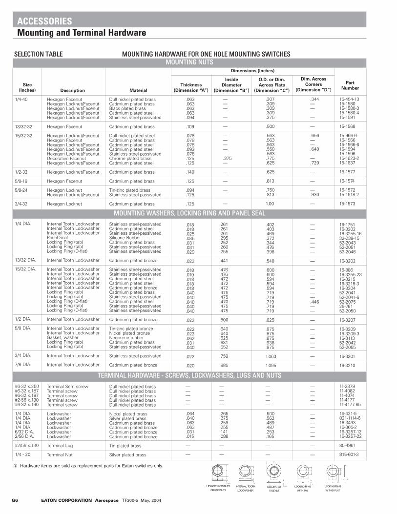
Size
(Inches)
1/4-40
13/32-32
15/32-32
1/2-32
5/8-18
5/8-24
3/4-32
Hexagon FacenutHexagon Locknut/FacenutHexagon Locknut/FacenutHexagon Locknut/FacenutHexagon Locknut/Facenut
Hexagon Facenut
Hexagon Locknut/FacenutHexagon FacenutHexagon Locknut/FacenutHexagon Locknut/FacenutHexagon Locknut/FacenutDecorative FacenutHexagon Locknut/Facenut
Hexagon Locknut/Facenut
Hexagon Facenut
Hexagon Locknut Hexagon Locknut/Facenut
Hexagon Locknut
Dull nickel plated brassCadmium plated brassBlack plated brassCadmium plated steelStainless steel-passivated
Cadmium plated brass
Dull nickel plated steelCadmium plated brassCadmium plated steelCadmium plated steelStainless steel-passivatedChrome plated brassCadmium plated steel
Cadmium plated brass
Cadmium plated brass
Tin-zinc plated brassStainless steel-passivated
Cadmium plated brass
.063
.063
.063
.063
.094
.109
.078
.078
.078
.093
.078
.125
.125
.140
.125
.094
.125
.125
.307
.309
.309
.309
.375
.500
.563
.563
.563
.558
.563
.775
.625
.625
.813
.750
.813
1.00
15-454-1315-158015-1580-315-1580-415-1591
15-1568
15-966-615-156615-1566-615-159415-159615-1623-215-1637
15-1577
15-1574
15-157215-1618-2
15-1573
—————
—
—————.375—
—
—
——
—
.344————
—
.656——.640——.720
—
—
—.930
—
Description
Dimensions (Inches)
Inside
Diameter
(Dimension “B”)
O.D. or Dim.
Across Flats
(Dimension “C”)
Dim. Across
Corners
(Dimension “D”)
Part
NumberMaterial
Thickness
(Dimension “A”)
SSEELLEECCTTIIOONN TTAABBLLEE MMOOUUNNTTIINNGG HHAARRDDWWAARREE FFOORR OONNEE HHOOLLEE MMOOUUNNTTIINNGG SSWWIITTCCHHEESS
1/4 DIA.
13/32 DIA.
15/32 DIA.
1/2 DIA.
5/8 DIA.
3/4 DIA.
7/8 DIA.
Internal Tooth LockwasherInternal Tooth LockwasherInternal Tooth LockwasherPanel SealLocking Ring (tab)Locking Ring (tab)Locking Ring (D-flat)
Internal Tooth Lockwasher
Internal Tooth LockwasherInternal Tooth LockwasherInternal Tooth LockwasherInternal Tooth LockwasherInternal Tooth LockwasherLocking Ring (tab)Locking Ring (tab)Locking Ring (D-flat)Locking Ring (tab)Locking Ring (D-flat)
Internal Tooth Lockwasher
Internal Tooth LockwasherInternal Tooth LockwasherGasket, washerLocking Ring (tab)Locking Ring (tab)
Internal Tooth Lockwasher
Internal Tooth Lockwasher
Stainless steel-passivatedCadmium plated steelStainless steel-passivatedSilicone RubberCadmium plated brassStainless steel-passivatedStainless steel-passivated
Cadmium plated bronze
Stainless steel-passivatedStainless steel-passivatedCadmium plated steelCadmium plated steelCadmium plated bronzeCadmium plated brassStainless steel-passivatedCadmium plated steelStainless steel-passivatedStainless steel-passivated
Cadmium plated bronze
Tin-zinc plated bronzeNickel plated bronzeNeoprene rubberCadmium plated brassStainless steel-passivated
Stainless steel-passivated
Cadmium plated bronze
.018
.018
.025
.035
.031
.031
.029
.022
.018
.019
.018
.018
.018
.040
.040
.048
.040
.040
.022
.022
.022
.062
.031
.040
.022
.020
.402
.403
.469
.372
.344
.476
.398
.540
.600
.600
.594
.594
.594
.719
.719
.719
.719
.719
.625
.875
.875
.875
.938
.875
1.063
1.095
16-175116-320216-3255-1632-239-1552-204352-205152-2046
16-3202
16-88616-3255-2316-321516-3215-316-320452-204152-2041-652-207529-76152-2050
16-3207
16-320916-3209-316-311352-204252-2055
16-3201
16-3210
.261
.261
.261
.295
.252
.260
.255
.441
.476
.476
.472
.472
.472
.475
.475
.470
.475
.475
.500
.640
.640
.625
.631
.652
.759
.885
———————
—
———————.446——
—
—————
—
—
#6-32 x.250#6-32 x.187#6-32 x.187#2-56 x.130#6-32 x.190
1/4 DIA.1/4 DIA.1/4 DIA.1/4 DIA.6/32 DIA.2/56 DIA.
#2/56 x.130
1/4 - 20
Terminal Sem screwTerminal screwTerminal screwTerminal screwTerminal screw
LockwasherLockwasherLockwasherLockwasherLockwasherLockwasher
Terminal Lug
Terminal Nut
Dull nickel plated brassDull nickel plated brassDull nickel plated brassDull nickel plated brassDull nickel plated brass
Nickel plated brassSilver plated brassCadmium plated brassCadmium plated bronzeCadmium plated bronzeCadmium plated bronze
Tin plated brass
Silver plated brass
—————
.064
.040
.062
.063
.031
.015
—
—
—————
.500
.562
.489
.487
.253
.165
—
—
11-237911-408211-407411-417711-4177-65
16-421-5821-1114-616-349316-365-216-3257-1216-3257-22
80-4961
815-601-3
—————
.265
.275
.259
.255
.141
.088
—
—
—————
——————
—
—
C
C
B
D
C
A
A
B
A
C
B
A
C
B
B
A
HEXAGON LOCKNUTSOR FACENUTS
INTERNAL TOOTHLOCKWASHER
LOCKING RINGWITH TAB
LOCKING RINGWITH D-FLAT
DECORATED FACENUT
ACCESSORIESMounting and Terminal Hardware
MMOOUUNNTTIINNGG NNUUTTSS
MMOOUUNNTTIINNGG WWAASSHHEERRSS,, LLOOCCKKIINNGG RRIINNGG AANNDD PPAANNEELL SSEEAALL
TTEERRMMIINNAALL HHAARRDDWWAARREE -- SSCCRREEWWSS,, LLOOCCKKWWAASSHHEERRSS,, LLUUGGSS AANNDD NNUUTTSS
1 Hardware items are sold as replacement parts for Eaton switches only.
G6 EATON CORPORATION Aerospace TF300-5 May, 2004

EATON CORPORATION Aerospace TF300-5 June, 2004 G7
Notes

Notes
G8 EATON CORPORATION Aerospace TF300-5 May, 2004

Military Part Number to Eaton Catalog Number H2 - H7
Test Requirements per MIL Specs H8 - H9
Glossary of Terms H10 - H12
Cross Reference
SECTION H
Index H1
EATON CORPORATION Aerospace TF300-5 June, 2004 H1

MMIILLIITTAARRYY PPAARRTT NNUUMMBBEERRSS TTOO EEAATTOONN CCAATTAALLOOGG NNUUMMBBEERRSS
Military Part
Number
Eaton
Catalog No.
MIL
Specification
Military Part
Number
Eaton
Catalog No.
MIL
Specification
Military Part
Number
Eaton
Catalog No.
MIL
Specification
AN3221-1-2
AN3223-1-2
AN3230-1-2-3
E1663-1-3
M3950/14A21A22A23A24A25A26A27A28A29A30A31A32A33B21B22B23B24B25B26B27B28B29B30B31B32B33B34B35
B36C21C22C23
M3950/14C24C25C26C27C28C29C30C31C32C33C34C35C36
M5423/16-01M8805/2
/4/5/11/11/14/14/14/15/15/16/17/18/19/20/38/39/40/43/53
M8805/55-001-002-003-004
M8805/93-001-002-003-004-005-006-007-008
24-193919-1939-2
8864K249-2033-2
8780K118781K118782K118790K48792K38546K1
K9K4K6K8K5K2K7K10K11K3K12K13
8547K1K9K4K6K8K5K2K7K10K11K3K12K13K15K16K17
8548K18548K9
K48548K6
K8K5K2K7K10K11K3K12K13K15K16
8548K1732-341
(see MS25085)(see MS24547)(see MS25350)(see MS25342)(see MS25343)(see MS25345)(see MS25346)(see MS25347)(see MS25348)(see MS25349)(see MS25351)(see MS25353)(see MS25356)(see MS25357)(see MS16712)(see MS27903)(see MS21321)(see MS24331)(see MS27248)(see MS27996)
8870K2K3K4K5
A3-212-01-02-03-04-05-06-07
A3-200-01
MIL-T-6750MIL-T-6750MIL-B-5423MIL-B-5423MIL-S-6745MIL-S-6745MIL-S-6745
XEL37XEL37
MIL-S-3950MIL-S-3950MIL-S-3950MIL-S-3950MIL-S-3950MIL-S-3950MIL-S-3950MIL-S-3950MIL-S-3950MIL-S-3950MIL-S-3950MIL-S-3950MIL-S-3950MIL-S-3950MIL-S-3950MIL-S-3950MIL-S-3950MIL-S-3950MIL-S-3950MIL-S-3950MIL-S-3950MIL-S-3950MIL-S-3950MIL-S-3950MIL-S-3950MIL-S-3950MIL-S-3950MIL-S-3950MIL-S-3950MIL-S-3950MIL-S-3950MIL-S-3950MIL-S-3950MIL-S-3950MIL-S-3950MIL-S-3950MIL-S-3950MIL-S-3950MIL-S-3950MIL-S-3950MIL-S-3950MIL-S-3950MIL-S-3950MIL-S-3950MIL-S-3950MIL-B-5423
MIL-S-8805/55MIL-S-8805/55MIL-S-8805/55MIL-S-8805/55MIL-S-8805/93MIL-S-8805/93MIL-S-8805/93MIL-S-8805/93MIL-S-8805/93MIL-S-8805/93MIL-S-8805/93MIL-S-8805/93
M8805/93-009-010-011-012-013-014-015-016-017-018-019-020-021-022-023-024-025-026-027-028
M8805/95-001-002-003-004
M8805/96-001-002-003-004-005-006-007-008-009-010-011-012-013-014-015-016
M22885/18-01-02-03-04-05-06-07-08
MS14001-212-222-232-242-262-272-282-292-302-312
MS14002-212-222-232-242-262-272-282-292-302-312
MS14003-212-222-232-242-262-272-282-292-302-312
MS16712-1MS16712-2MS18150-1MS18151-1MS18152-1
MS21026-A211-B211-B241-C221
A3-200-02-03-04-05-06-07
A3-202-01-02-03-04-05
A3-202-06-07
A3-204-01-02-03
A3-204-04-05-06-07
B7070B7070RB7070B
B7070BRB9001RB9001BB9002RB9002B
B9001BRB9001BBB9002BRB9002BB
BW9001RBW9001BBW9002RBW9002B
BW9001BRBW9001BBBW9002BRBW9002BB
A20267J20145A20271J20149A20272J20152A20273J20153
8836K91K99K94K96K95K92K97K910K911K93
8837K91K99K94K96K95K92K97K910K911K93
8838K91K99K94K96K95K92K97K910K911K93
C20050C20050RTW20001TW20002TW20000
8855K4K5K19K13
MIL-S-8805/93MIL-S-8805/93MIL-S-8805/93MIL-S-8805/93MIL-S-8805/93MIL-S-8805/93MIL-S-8805/93MIL-S-8805/93MIL-S-8805/93MIL-S-8805/93MIL-S-8805/93MIL-S-8805/93MIL-S-8805/93MIL-S-8805/93MIL-S-8805/93MIL-S-8805/93MIL-S-8805/93MIL-S-8805/93MIL-S-8805/93MIL-S-8805/93MIL-S-8805/95MIL-S-8805/95MIL-S-8805/95MIL-S-8805/95MIL-S-8805/96MIL-S-8805/96MIL-S-8805/96MIL-S-8805/96MIL-S-8805/96MIL-S-8805/96MIL-S-8805/96MIL-S-8805/96MIL-S-8805/96MIL-S-8805/96MIL-S-8805/96MIL-S-8805/96MIL-S-8805/96MIL-S-8805/96MIL-S-8805/96MIL-S-8805/96MIL-S-22885MIL-S-22885MIL-S-22885MIL-S-22885MIL-S-22885MIL-S-22885MIL-S-22885MIL-S-22885MIL-S-8834MIL-S-8834MIL-S-8834MIL-S-8834MIL-S-8834MIL-S-8834MIL-S-8834MIL-S-8834MIL-S-8834MIL-S-8834MIL-S-8834MIL-S-8834MIL-S-8834MIL-S-8834MIL-S-8834MIL-S-8834MIL-S-8834MIL-S-8834MIL-S-8834MIL-S-8834MIL-S-8834MIL-S-8834MIL-S-8834MIL-S-8834MIL-S-8834MIL-S-8834MIL-S-8834MIL-S-8834MIL-S-8834MIL-S-8834
MIL-S-8805/20MIL-S-8805/20MIL-S-83731MIL-S-83731MIL-S-83731MIL-S-8834MIL-S-8834MIL-S-8834MIL-S-8834
MS21026-C231-D211-E221-E231-F271-G311-H271-J241-K281-K311-L311
MS21027-A211-A331-A711-A831-B211-B241-B331-B711-B741-B831-C221-C231-C331-C721-C731-C831-D211-D331-D711-D831-E221-E231-E721-E731-F341-F371-F841-F871-G311-G351-G811-G851-H341-H371-H841-H871-J241-J741-K311-K321-K351-K381-K811-K821-K851-K881-L311-L351-L811-L851
MS21321-1-2
MS21346-211-221-231-241-271-281-311-321
-A211-B211-B241-C221-C231-D211-E221-E231-F271-G311-H271-J241-K281-K311-L311
8855K7K10K14K8K15K16K17K9K18K20K12
8856K4K21K4XK21XK5K19K30K5XK19XK30XK13K7K31K13XK7XK31XK10K32K10XK32XK14K8K14XK8XK22K27K22XK27XK16K35K16XK35X
8856K34K29K34XK29XK9K9XK20K24K23K28K20XK24XK23XK28XK12K36K12XK36X
H11-335H11-3958868K51
K57K54K55K52K56K53K58
8855K54K55K519K513K57K510K514K58K515K516K517K59K518K520K512
MIL-S-8834MIL-S-8834MIL-S-8834MIL-S-8834MIL-S-8834MIL-S-8834MIL-S-8834MIL-S-8834MIL-S-8834MIL-S-8834MIL-S-8834MIL-S-8834MIL-S-8834MIL-S-8834MIL-S-8834MIL-S-8834MIL-S-8834MIL-S-8834MIL-S-8834MIL-S-8834MIL-S-8834MIL-S-8834MIL-S-8834MIL-S-8834MIL-S-8834MIL-S-8834MIL-S-8834MIL-S-8834MIL-S-8834MIL-S-8834MIL-S-8834MIL-S-8834MIL-S-8834MIL-S-8834MIL-S-8834MIL-S-8834MIL-S-8834MIL-S-8834MIL-S-8834MIL-S-8834MIL-S-8834MIL-S-8834MIL-S-8834MIL-S-8834MIL-S-8834MIL-S-8834MIL-S-8834MIL-S-8834MIL-S-8834MIL-S-8834MIL-S-8834MIL-S-8834MIL-S-8834MIL-S-8834MIL-S-8834MIL-S-8834MIL-S-8834MIL-S-8834MIL-S-8834MIL-S-8834MIL-S-8834
MIL-S-8805/39MIL-S-8805/39
MIL-S-8834MIL-S-8834MIL-S-8834MIL-S-8834MIL-S-8834MIL-S-8834MIL-S-8834MIL-S-8834MIL-S-8834MIL-S-8834MIL-S-8834MIL-S-8834MIL-S-8834MIL-S-8834MIL-S-8834MIL-S-8834MIL-S-8834MIL-S-8834MIL-S-8834MIL-S-8834MIL-S-8834MIL-S-8834MIL-S-8834
H2 EATON CORPORATION Aerospace TF300-5 June, 2004
REFERENCE DOCUMENTSCross Reference

MS21357-221-231-241-271-281-311-321-331-341-351
MS21357-711-721-731-741-771-781-811-821-831-841-851
MS21433-211-221-231-241-271-281-311-321
MS21434-211-221-231-241-271-281-311-321-331-341-351
MS21436-A211-B211-B241-C221-C231-D211-E221-E231-F271-G11-H271-J241-K281-K311-L311
MS21437-A211-A331-A711-A831-B211-B241-B331-B711-B741-B831-C221-C231-C331-C721-C731-C831-D211-D331-D711-D831-E221-E231-E721-E731-F341-F371-F841-F871-G311-G351-G811-G851
8869K67K64K65K62K66K63K68K69K611K610
8869K61XK67XK64XK65XK62XK66XK63XK68XK69XK611XK610X
8866KA61KA67KA64KA65KA62KA66KA63KA68
8867KA61KA67KA64KA65KA62KA66KA63KA68KA69KA611KA610
8855K74K75K719K713K77K710K714K78K715K716K717K79K718K720K712
8856K74K721
8856K74XK21XK75K719K730K75XK719XK730XK713K77K731K713XK77XK731XK710K732K710XK732XK714K78K714XK78XK722K727K722XK727XK716K735K716XK735X
MIL-S-8834MIL-S-8834MIL-S-8834MIL-S-8834MIL-S-8834MIL-S-8834MIL-S-8834MIL-S-8834MIL-S-8834MIL-S-8834MIL-S-8834MIL-S-8834MIL-S-8834MIL-S-8834MIL-S-8834MIL-S-8834MIL-S-8834MIL-S-8834MIL-S-8834MIL-S-8834MIL-S-8834MIL-S-8834MIL-S-8834MIL-S-8834MIL-S-8834MIL-S-8834MIL-S-8834MIL-S-8834MIL-S-8834MIL-S-8834MIL-S-8834MIL-S-8834MIL-S-8834MIL-S-8834MIL-S-8834MIL-S-8834MIL-S-8834MIL-S-8834MIL-S-8834MIL-S-8834MIL-S-8834MIL-S-8834MIL-S-8834MIL-S-8834MIL-S-8834MIL-S-8834MIL-S-8834MIL-S-8834MIL-S-8834MIL-S-8834MIL-S-8834MIL-S-8834MIL-S-8834MIL-S-8834MIL-S-8834MIL-S-8834MIL-S-8834MIL-S-8834MIL-S-8834MIL-S-8834MIL-S-8834MIL-S-8834MIL-S-8834MIL-S-8834MIL-S-8834MIL-S-8834MIL-S-8834MIL-S-8834MIL-S-8834MIL-S-8834MIL-S-8834MIL-S-8834MIL-S-8834MIL-S-8834MIL-S-8834MIL-S-8834MIL-S-8834MIL-S-8834MIL-S-8834MIL-S-8834MIL-S-8834MIL-S-8834MIL-S-8834MIL-S-8834MIL-S-8834MIL-S-8834MIL-S-8834
MS21437-H341-H371-H841-H871-J241-J741-K311-K321-K351-K381-K811-K821-K851-K881-L311-L351-L811-L851
MS24331-1MS24417-1MS24523-21
-22-23-24-25-26-27-28-29-30-31-32-33
MS24524-21-22-23-24-25-26-27-28-29-30-31-32-33
MS24525-21-22-23-24-25-26-27-28-29-30-31-32-33
MS24547-1-2-3-4-5
MS24612-A212-B212-B242-C212-C222-C232-D212-E212-E222-E232-F272-G312-H272-J242-K282-K312-L262-L292-L302-M312-N312
MS24613-A212-B212
8856K734K729K734XK729XK79K79XK720K724K723K728K720XK724XK723XK728XK712K736K712XK736X
H11-3758492K18500K1
K9K4K6K8K5K2K7K10K11K3K12K13
8501K1K9K4K6K8K5K2K7K10K11K3K12K13
8502K1K9K4K6K8K5K2K7K10K11K3K12K13
SS30AT40KT40DT40AT41KT41
8843K1K2K16K3K9K7K4K5K10K6K12K13K14K11K15K18K20K21K19K8K17
8844K1K2
MIL-S-8834MIL-S-8834MIL-S-8834MIL-S-8834MIL-S-8834MIL-S-8834MIL-S-8834MIL-S-8834MIL-S-8834MIL-S-8834MIL-S-8834MIL-S-8834MIL-S-8834MIL-S-8834MIL-S-8834MIL-S-8834MIL-S-8834MIL-S-8834
MIL-S-8805/40MIL-G-7703MIL-S-3950MIL-S-3950MIL-S-3950MIL-S-3950MIL-S-3950MIL-S-3950MIL-S-3950MIL-S-3950MIL-S-3950MIL-S-3950MIL-S-3950MIL-S-3950MIL-S-3950MIL-S-3950MIL-S-3950MIL-S-3950MIL-S-3950MIL-S-3950MIL-S-3950MIL-S-3950MIL-S-3950MIL-S-3950MIL-S-3950MIL-S-3950MIL-S-3950MIL-S-3950MIL-S-3950MIL-S-3950MIL-S-3950MIL-S-3950MIL-S-3950MIL-S-3950MIL-S-3950MIL-S-3950MIL-S-3950MIL-S-3950MIL-S-3950MIL-S-3950MIL-S-3950
MIL-S-8805/4 MIL-S-8805/4 MIL-S-8805/4 MIL-S-8805/4 MIL-S-8805/4 MIL-S-8834MIL-S-8834MIL-S-8834MIL-S-8834MIL-S-8834MIL-S-8834MIL-S-8834MIL-S-8834MIL-S-8834MIL-S-8834MIL-S-8834MIL-S-8834MIL-S-8834MIL-S-8834MIL-S-8834MIL-S-8834MIL-S-8834MIL-S-8834MIL-S-8834MIL-S-8834MIL-S-8834MIL-S-8834MIL-S-8834
EATON CORPORATION Aerospace TF300-5 June, 2004 H3
MMIILLIITTAARRYY PPAARRTT NNUUMMBBEERRSS TTOO EEAATTOONN CCAATTAALLOOGG NNUUMMBBEERRSS
MS21347-211-821-831-841-851-A211-A331-B211-B241-B331-C221-C231-C331-D211-D331-E221-E231-F271-F341-F371-G311-G351-H271-H341-H371-J241-K281-K311-K321-K351-K381-L311-L351-221-231-241-271-281-311-321-331-341-351
-711-721-731-741-771-781-811
MS21351-321MS21353-321
-331-341-351-821-831-841-851
MS21354-211-221-231-241-271-281-311-321
MS21355-211-221-231-241-271-281-311-321-331-341-351
MS21356-211-221-231-241-271-281-311-321
MS21357-211
8869K51K58XK59XK511XK510X
8856K54K521K55K519K530K513K57K531K510K532K514K58K515K522K527K516K535K517K534K529K59K518K520K524K523K528K512K536
8869K57K54K55K52K56K53K58K59K511K510K51XK57XK54XK55XK52XK56XK53X
8868K88869K8
K9K11K10K8XK9XK11XK10X
8866K61K67K64K65K62K66K63K68
8867K61K67K64K65K62K66K63K68K69K611K610
8868K61K67K64K65K62K66K63K68
8869K61
MIL-S-8834MIL-S-8834MIL-S-8834MIL-S-8834MIL-S-8834MIL-S-8834MIL-S-8834MIL-S-8834MIL-S-8834MIL-S-8834MIL-S-8834MIL-S-8834MIL-S-8834MIL-S-8834MIL-S-8834MIL-S-8834MIL-S-8834MIL-S-8834MIL-S-8834MIL-S-8834MIL-S-8834MIL-S-8834MIL-S-8834MIL-S-8834MIL-S-8834MIL-S-8834MIL-S-8834MIL-S-8834MIL-S-8834MIL-S-8834MIL-S-8834MIL-S-8834MIL-S-8834MIL-S-8834MIL-S-8834MIL-S-8834MIL-S-8834MIL-S-8834MIL-S-8834MIL-S-8834MIL-S-8834MIL-S-8834MIL-S-8834MIL-S-8834MIL-S-8834MIL-S-8834MIL-S-8834MIL-S-8834MIL-S-8834MIL-S-8834MIL-S-8834MIL-S-8834MIL-S-8834MIL-S-8834MIL-S-8834MIL-S-8834MIL-S-8834MIL-S-8834MIL-S-8834MIL-S-8834MIL-S-8834MIL-S-8834MIL-S-8834MIL-S-8834MIL-S-8834MIL-S-8834MIL-S-8834MIL-S-8834MIL-S-8834MIL-S-8834MIL-S-8834MIL-S-8834MIL-S-8834MIL-S-8834MIL-S-8834MIL-S-8834MIL-S-8834MIL-S-8834MIL-S-8834MIL-S-8834MIL-S-8834MIL-S-8834MIL-S-8834MIL-S-8834MIL-S-8834MIL-S-8834MIL-S-8834
Military Part
Number
Eaton
Catalog No.
MIL
Specification
Military Part
Number
Eaton
Catalog No.
MIL
Specification
Military Part
Number
Eaton
Catalog No.
MIL
Specification
REFERENCE DOCUMENTSCross Reference

MS24613-B242-C212-C222-C232-D212-E212-E222-E232-F272-G312-H272-J242-K282-K312-L262-L292-L302-M312-N312
MS24614-A212-B212-B242-C212-C222-C232-D212-E212-E222-E232-F272-G312-H272-J242-K282-K312-L262-L292-L302-M312-N312
MS24655-211-221-231-241-271-281-311-321-211W-221W-231W-241W-271W-281W-311W-321W
MS24656-211-221-231-241-271-281-311-321-331-341-351-211W-221W-231W-241W-271W-281W-311W-321W-331W-341W-351W
MS24658-21A-21B-21D-21E-21F-21G-21H-21J21K
8844K16K3K9K7K4K5K10K6K12K13K14K11K15K18K20K21K19K8K17
8845K1K2K16K3K9K7K4K5K10K6K12K13K14K11K15K18K20K21K19K8K17
8866K1K7K4K5K2K6K3K8K51K57K54K55K52K56K53K58
8867K1K7K4K5K2K6K3K8K9K11K10K51K57K54K55K52K56K53K58K59K511K510
8503K1K27K5K2K28K3K29K30K31
MIL-S-8834MIL-S-8834MIL-S-8834MIL-S-8834MIL-S-8834MIL-S-8834MIL-S-8834MIL-S-8834MIL-S-8834MIL-S-8834MIL-S-8834MIL-S-8834MIL-S-8834MIL-S-8834MIL-S-8834MIL-S-8834MIL-S-8834MIL-S-8834MIL-S-8834MIL-S-8834MIL-S-8834MIL-S-8834MIL-S-8834MIL-S-8834MIL-S-8834MIL-S-8834MIL-S-8834MIL-S-8834MIL-S-8834MIL-S-8834MIL-S-8834MIL-S-8834MIL-S-8834MIL-S-8834MIL-S-8834MIL-S-8834MIL-S-8834MIL-S-8834MIL-S-8834MIL-S-8834MIL-S-8834MIL-S-8834MIL-S-8834MIL-S-8834MIL-S-8834MIL-S-8834MIL-S-8834MIL-S-8834MIL-S-8834MIL-S-8834MIL-S-8834MIL-S-8834MIL-S-8834MIL-S-8834MIL-S-8834MIL-S-8834MIL-S-8834MIL-S-8834MIL-S-8834MIL-S-8834MIL-S-8834MIL-S-8834MIL-S-8834MIL-S-8834MIL-S-8834MIL-S-8834MIL-S-8834MIL-S-8834MIL-S-8834MIL-S-8834MIL-S-8834MIL-S-8834MIL-S-8834MIL-S-8834MIL-S-8834MIL-S-8834MIL-S-8834MIL-S-8834MIL-S-3950MIL-S-3950MIL-S-3950MIL-S-3950MIL-S-3950MIL-S-3950MIL-S-3950MIL-S-3950MIL-S-3950
Military Part
Number
Eaton
Catalog No.
MIL
Specification
MS24658-21L-21M-21N-21P-22D-22F-22G-23D-23F-23G-24E-24F-24K-24M-25F-26F-27E-27L-27N-28E-29F-30F-31E-31F-31K-31L-31M-31N-32E-33E-33F-33K-33M
MS24659-21A-21B-21D-21E-21F-21G-21H-21J-21K-21L-21M-21N-21P-22D-22F-22G-23D-23F-23G-24E-24F-24K-24M-25F-26F-27E-27L-27N-28E-29F-30F-31E-31F-31K-31L-31M-31N-32E-33E-33F-33K-33M
MS24660-21A-21B-21D-21E-21F-21G-21H-21J-21K-21L-21M-21N
8503K32K33K4K34K10K35K9K6K36K7K16K37K38K11K22K20K12K39K14K15K21K19K18K40K41K13K17K8K23K24K25K26K42
8504K1K27K5K2K28K3K29K30K31K32K33K4K34K10K35K9K6K36K7K16K37K38K11K22K20K12K39K14K15K21K19K18K40K41K13K17K8K23K24K25K26K42
8505K1K27K5K2K28K3K29K30K31K32K33K4
MIL-S-3950MIL-S-3950MIL-S-3950MIL-S-3950MIL-S-3950MIL-S-3950MIL-S-3950MIL-S-3950MIL-S-3950MIL-S-3950MIL-S-3950MIL-S-3950MIL-S-3950MIL-S-3950MIL-S-3950MIL-S-3950MIL-S-3950MIL-S-3950MIL-S-3950MIL-S-3950MIL-S-3950MIL-S-3950MIL-S-3950MIL-S-3950MIL-S-3950MIL-S-3950MIL-S-3950MIL-S-3950MIL-S-3950MIL-S-3950MIL-S-3950MIL-S-3950MIL-S-3950MIL-S-3950MIL-S-3950MIL-S-3950MIL-S-3950MIL-S-3950MIL-S-3950MIL-S-3950MIL-S-3950MIL-S-3950MIL-S-3950MIL-S-3950MIL-S-3950MIL-S-3950MIL-S-3950MIL-S-3950MIL-S-3950MIL-S-3950MIL-S-3950MIL-S-3950MIL-S-3950MIL-S-3950MIL-S-3950MIL-S-3950MIL-S-3950MIL-S-3950MIL-S-3950MIL-S-3950MIL-S-3950MIL-S-3950MIL-S-3950MIL-S-3950MIL-S-3950MIL-S-3950MIL-S-3950MIL-S-3950MIL-S-3950MIL-S-3950MIL-S-3950MIL-S-3950MIL-S-3950MIL-S-3950MIL-S-3950MIL-S-3950MIL-S-3950MIL-S-3950MIL-S-3950MIL-S-3950MIL-S-3950MIL-S-3950MIL-S-3950MIL-S-3950MIL-S-3950MIL-S-3950MIL-S-3950
Military Part
Number
Eaton
Catalog No.
MIL
Specification
MS24660-21P-22D-22F-22G-23D-23F-23G-24E-24F-24K-24M-25F-26F-27E-27L-27N-28E-29F-30F-31E-31F-31K-31L-31M-31N-32E-33E-33F-33K-33M
MS25081-4MS25082-8MS25085-1MS25085-2MS25214-1
-2-3
MS25221-1MS25223-1
-2MS25224-1
-2-3
MS25225-1-2-3
MS25246-1MS25301-1MS25306-212
-222-232-242-262-272-282-292-302-312
MS25307-212-222-232-242-262-272-282-292-302-312
MS25308-212-222-232-242-262-272-282-292-302-312
MS25342-1MS25343-1MS25344-1MS25345-1MS25346-1MS25347-1MS25348-1MS25349-1MS25350-1
8505K34K10K35K9K6K36K7K16K37K38K11K22K20K12K39K14K15K21K19K18K40K41K13K17K8K23K24K25K26K42
29-76115-404-6E4-270E4-2718494K1
K2K3
8495K18496K1
K28497K1
K2K3
8498K1K2K3
24-1164-249-1740-28836K1
K9K4K6K5K2K7K10K11K3
8837K1K9K4K6K5K2K7K10K11K3
8838K1K9K4K6K5K2K7K10K11K3
S1-44S3-44S2-44S1-344S3-344S2-344D4-44D8-44D4-344
MIL-S-3950MIL-S-3950MIL-S-3950MIL-S-3950MIL-S-3950MIL-S-3950MIL-S-3950MIL-S-3950MIL-S-3950MIL-S-3950MIL-S-3950MIL-S-3950MIL-S-3950MIL-S-3950MIL-S-3950MIL-S-3950MIL-S-3950MIL-S-3950MIL-S-3950MIL-S-3950MIL-S-3950MIL-S-3950MIL-S-3950MIL-S-3950MIL-S-3950MIL-S-3950MIL-S-3950MIL-S-3950MIL-S-3950MIL-S-3950MIL-S-3950MIL-S-83731MIL-S-8805/2MIL-S-8805/2MIL-S-7703MIL-G-7703MIL-G-7703MIL-G-7703MIL-G-7703MIL-G-7703MIL-G-7703MIL-G-7703MIL-G-7703MIL-G-7703MIL-G-7703MIL-G-7703
MIL-B-5423MIL-S-8834MIL-S-8834MIL-S-8834MIL-S-8834MIL-S-8834MIL-S-8834MIL-S-8834MIL-S-8834MIL-S-8834MIL-S-8834MIL-S-8834MIL-S-8834MIL-S-8834MIL-S-8834MIL-S-8834MIL-S-8834MIL-S-8834MIL-S-8834MIL-S-8834MIL-S-8834MIL-S-8834MIL-S-8834MIL-S-8834MIL-S-8834MIL-S-8834MIL-S-8834MIL-S-8834MIL-S-8834MIL-S-8834MIL-S-8834
MIL-S-8805/11MIL-S-8805/11MIL-S-8805/11MIL-S-8805/14MIL-S-8805/14MIL-S-8805/14MIL-S-8805/15MIL-S-8805/15MIL-S-8805/5
Military Part
Number
Eaton
Catalog No.
MIL
Specification
MMIILLIITTAARRYY PPAARRTT NNUUMMBBEERRSS TTOO EEAATTOONN CCAATTAALLOOGG NNUUMMBBEERRSS
H4 EATON CORPORATION Aerospace TF300-5 June, 2004
REFERENCE DOCUMENTSCross Reference

REFERENCE DOCUMENTSCross Reference
MS25351-1MS25353-1MS25356-1MS25357-1MS25452-1MS27240-1
-2-3-4
MS27259-1-2
MS27406-1-2-3
MS27407-1-2-3-4-5-6
MS27408-1A-1B-1D-1E-1F-1G-1H-1J-1K-1L-1M-1N-1P-2E-2F-2K-2L-2M-2N-3E-3L-3N-4A-4B-4D-4E-4F-4G-4H-4J-4K-4L-4M-4N-4P-5E-5F-5K-5L-5M-5N-6E-6L-6N-7B
MS27409-1A-1B-1D-1E-1F-1G-1H-1J-1K-1L-1M-1N-1P-2E-2F-2K-2L-2M-2N-3E-3L-3N
D8-344K3-344K3-44G3-448499K1H11-330
-390-331-391
H11-334-394
8502K15K16K17
8501K14K15K16K17K18K19
8504K43K44K45K46K47K48K49K50K51K52K53K54K55K56K57K58K59K60K61K62K63K64
8504K65K66K67K68K69K70K71K72K73K74K75K76K77K78K79K80K81K82K83K84K85K86K87
8505K43K44K45K46K47K48K49K50K51K52K53K54K55K56K57K58K59K60K61K62K63K64
MIL-S-8805/16MIL-S-8805/17MIL-S-8805/18MIL-S-8805/19
MIL-G-7703MIL-S-8805/43
MIL-S-8805MIL-S-8805/43
MIL-S-8805MIL-S-8805MIL-S-8805MIL-S-3950MIL-S-3950MIL-S-3950MIL-S-3950MIL-S-3950MIL-S-3950MIL-S-3950MIL-S-3950MIL-S-3950MIL-S-3950MIL-S-3950MIL-S-3950MIL-S-3950MIL-S-3950MIL-S-3950MIL-S-3950MIL-S-3950MIL-S-3950MIL-S-3950MIL-S-3950MIL-S-3950MIL-S-3950MIL-S-3950MIL-S-3950MIL-S-3950MIL-S-3950MIL-S-3950MIL-S-3950MIL-S-3950MIL-S-3950MIL-S-3950MIL-S-3950MIL-S-3950MIL-S-3950MIL-S-3950MIL-S-3950MIL-S-3950MIL-S-3950MIL-S-3950MIL-S-3950MIL-S-3950MIL-S-3950MIL-S-3950MIL-S-3950MIL-S-3950MIL-S-3950MIL-S-3950MIL-S-3950MIL-S-3950MIL-S-3950MIL-S-3950MIL-S-3950MIL-S-3950MIL-S-3950MIL-S-3950MIL-S-3950MIL-S-3950MIL-S-3950MIL-S-3950MIL-S-3950MIL-S-3950MIL-S-3950MIL-S-3950MIL-S-3950MIL-S-3950MIL-S-3950MIL-S-3950MIL-S-3950MIL-S-3950MIL-S-3950MIL-S-3950MIL-S-3950MIL-S-3950MIL-S-3950MIL-S-3950MIL-S-3950
Military Part
Number
Eaton
Catalog No.
MIL
Specification
MS27722-21-22-23-24-25-26-27-28-29-30-31-32-33
MS27723-1-2-3-21-22-23-24-25-26-27-28-29-30-31-32-33
MS27724-1-2-3-21-22-23-24-25-26-27-28-29-30-31-32-33
MS27752-1MS27781-21A
-21B-21D-21E-21F-21G-21H-21J-21K-21L-21M-21N-21P-22D-22F-22G-23D-23F-23G-24E-24F-24K-24M-25F-26F-27E-27L-27N-28E-29F-30F-31E-31F-31K-31L-31M-31N-32E-33E-33F-33K
8570K1-16K9-16K4-16K6-16K8-16K5-16K2-16K7-16K10-16K11-16K3-16K12-16K13-16
8571K17-16K18-16K19-16K1-16K9-16K4-16K6-16K8-16K5-16K2-16K7-16K10-16K11-16K3-16K12-16K13-16
8572K15-16K16-16K17-16K1-16K9-16K4-16K6-16K8-16K5-16K2-16K7-16K10-16K11-16K3-16K12-16K13-16
8498K68573K1-16
K27-16K5-16K2-16K28-16K3-16K29-16K30-16K31-16K32-16K33-16K4-16K34-16K10-16K35-16K9-16K6-16K36-16K7-16K16-16K37-16K38-16K11-16K22-16K20-16K12-16K39-16K14-16K15-16K21-16K19-16K18-16K40-16K41-16K13-16K17-16K8-16K23-16K24-16K25-16K26-16
MIL-S-3950MIL-S-3950MIL-S-3950MIL-S-3950MIL-S-3950MIL-S-3950MIL-S-3950MIL-S-3950MIL-S-3950MIL-S-3950MIL-S-3950MIL-S-3950MIL-S-3950MIL-S-3950MIL-S-3950MIL-S-3950MIL-S-3950MIL-S-3950MIL-S-3950MIL-S-3950MIL-S-3950MIL-S-3950MIL-S-3950MIL-S-3950MIL-S-3950MIL-S-3950MIL-S-3950MIL-S-3950MIL-S-3950MIL-S-3950MIL-S-3950MIL-S-3950MIL-S-3950MIL-S-3950MIL-S-3950MIL-S-3950MIL-S-3950MIL-S-3950MIL-S-3950MIL-S-3950MIL-S-3950MIL-S-3950MIL-S-3950MIL-S-3950MIL-S-3950MIL-G-7703MIL-S-3950MIL-S-3950MIL-S-3950MIL-S-3950MIL-S-3950MIL-S-3950MIL-S-3950MIL-S-3950MIL-S-3950MIL-S-3950MIL-S-3950MIL-S-3950MIL-S-3950MIL-S-3950MIL-S-3950MIL-S-3950MIL-S-3950MIL-S-3950MIL-S-3950MIL-S-3950MIL-S-3950MIL-S-3950MIL-S-3950MIL-S-3950MIL-S-3950MIL-S-3950MIL-S-3950MIL-S-3950MIL-S-3950MIL-S-3950MIL-S-3950MIL-S-3950MIL-S-3950MIL-S-3950MIL-S-3950MIL-S-3950MIL-S-3950MIL-S-3950MIL-S-3950MIL-S-3950MIL-S-3950
Military Part
Number
Eaton
Catalog No.
MIL
Specification
MS27781-33MMS27782-1A
-1B-1D-1E-1F-1G-1H-1J-1K-1L-1M-1N-1P-2E-2F-2K-2L-2M-2N
MS27782-3E-3L-3N-21A-21B-21D-21E-21F-21G-21H-21J-21K-21L-21M-21N-21P-22D-22F-22G-23D-23F-23G-24E-24F-24K-24M-25F-26F-27E-27L-27N-28E-29F-30F-31E-31F-31K-31L-31M-31N-32E-33E-33F-33K-33M
MS27783-1A-1B-1D-1E-1K-1L-1M-1N-1P-2E-2F-2K-2L-2M-2N-3E-3L-3N-21A-21B-21D-21E
8573K42-168575K65-16
K66-16K67-16K68-16K69-16K70-16K71-16K72-16K73-16K74-16K75-16K76-16K77-16K78-16K79-16K80-16K81-16K82-16K83-16
8574K84-16K85-16K86-16K1-16K27-16K5-16K2-16K28-16K3-16K29-16K30-16K31-16K32-16K33-16K4-16K34-16K10-16K35-16K9-16K6-16K36-16K7-16K16-16K37-16K38-16K11-16K22-16K20-16K12-16K39-16K14-16K15-16K21-16K19-16K18-16K40-16K41-16K13-16K17-16K8-16K23-16K24-16K25-16K26-16K42-16
8575K43-16K44-16K45-16K46-16K51-16K52-16K53-16K54-16K55-16K56-16K57-16K58-16K59-16K60-16K61-16K62-16K63-16K64-16K1-16K27-16K5-16K2-16
MIL-S-3950MIL-S-3950MIL-S-3950MIL-S-3950MIL-S-3950MIL-S-3950MIL-S-3950MIL-S-3950MIL-S-3950MIL-S-3950MIL-S-3950MIL-S-3950MIL-S-3950MIL-S-3950MIL-S-3950MIL-S-3950MIL-S-3950MIL-S-3950MIL-S-3950MIL-S-3950MIL-S-3950MIL-S-3950MIL-S-3950MIL-S-3950MIL-S-3950MIL-S-3950MIL-S-3950MIL-S-3950MIL-S-3950MIL-S-3950MIL-S-3950MIL-S-3950MIL-S-3950MIL-S-3950MIL-S-3950MIL-S-3950MIL-S-3950MIL-S-3950MIL-S-3950MIL-S-3950MIL-S-3950MIL-S-3950MIL-S-3950MIL-S-3950MIL-S-3950MIL-S-3950MIL-S-3950MIL-S-3950MIL-S-3950MIL-S-3950MIL-S-3950MIL-S-3950MIL-S-3950MIL-S-3950MIL-S-3950MIL-S-3950MIL-S-3950MIL-S-3950MIL-S-3950MIL-S-3950MIL-S-3950MIL-S-3950MIL-S-3950MIL-S-3950MIL-S-3950MIL-S-3950MIL-S-3950MIL-S-3950MIL-S-3950MIL-S-3950MIL-S-3950MIL-S-3950MIL-S-3950MIL-S-3950MIL-S-3950MIL-S-3950MIL-S-3950MIL-S-3950MIL-S-3950MIL-S-3950MIL-S-3950MIL-S-3950MIL-S-3950MIL-S-3950MIL-S-3950MIL-S-3950MIL-S-3950
Military Part
Number
Eaton
Catalog No.
MIL
Specification
MMIILLIITTAARRYY PPAARRTT NNUUMMBBEERRSS TTOO EEAATTOONN CCAATTAALLOOGG NNUUMMBBEERRSS
EATON CORPORATION Aerospace TF300-5 June, 2004 H5

H6 EATON CORPORATION Aerospace TF300-5 June, 2004
MS27783-21F-21G-21H-21J-21K-21L-21M-21N-21P-22D-22F-22G-23D-23F-23G-24E-24F-24K-24M-25F-26F-27E-27L-27N-28E-29F-30F-31E-31F-31K-31L-31M-31N-32E-33E-33F-33K-33M
MS27784-21-22-23-24-25-26-27-28-29-30-31-32-33
MS27785-1-2-3-21-22-23-24-25-26-27-28-29-30-31-32-33
MS27786-1-2-3-21-22-23-24-25-26-27-28-29-30-31-32-33
MS27787-21A-21B-21D-21E
8575K28-16K3-16K29-16K30-16K31-16K32-16K33-16K4-16K34-16K10-16K35-16K9-16K6-16K36-16K7-16K16-16K37-16K38-16K11-16K22-16K20-16K12-16K39-16K14-16K15-16K21-16K19-16K18-16K40-16K41-16K13-16K17-16K8-16K23-16K24-16K25-16K26-16K42-16
8570K1-20K9-20K4-20K6-20K8-20K5-20K2-20K7-20K10-20K11-20K3-20K12-20K13-20
8571K17-20K18-20K19-20K1-20K9-20K4-20K6-20K8-20K5-20K2-20K7-20K10-20K11-20K3-20K12-20K13-20
8572K15-20K16-20K17-20K1-20K9-20K4-20K6-20K8-20K5-20K2-20K7-20K10-20K11-20K3-20K12-20K13-20
8573K1-20K27-20K5-20K2-20
MIL-S-3950MIL-S-3950MIL-S-3950MIL-S-3950MIL-S-3950MIL-S-3950MIL-S-3950MIL-S-3950MIL-S-3950MIL-S-3950MIL-S-3950MIL-S-3950MIL-S-3950MIL-S-3950MIL-S-3950MIL-S-3950MIL-S-3950MIL-S-3950MIL-S-3950MIL-S-3950MIL-S-3950MIL-S-3950MIL-S-3950MIL-S-3950MIL-S-3950MIL-S-3950MIL-S-3950MIL-S-3950MIL-S-3950MIL-S-3950MIL-S-3950MIL-S-3950MIL-S-3950MIL-S-3950MIL-S-3950MIL-S-3950MIL-S-3950MIL-S-3950MIL-S-3950MIL-S-3950MIL-S-3950MIL-S-3950MIL-S-3950MIL-S-3950MIL-S-3950MIL-S-3950MIL-S-3950MIL-S-3950MIL-S-3950MIL-S-3950MIL-S-3950MIL-S-3950MIL-S-3950MIL-S-3950MIL-S-3950MIL-S-3950MIL-S-3950MIL-S-3950MIL-S-3950MIL-S-3950MIL-S-3950MIL-S-3950MIL-S-3950MIL-S-3950MIL-S-3950MIL-S-3950MIL-S-3950MIL-S-3950MIL-S-3950MIL-S-3950MIL-S-3950MIL-S-3950MIL-S-3950MIL-S-3950MIL-S-3950MIL-S-3950MIL-S-3950MIL-S-3950MIL-S-3950MIL-S-3950MIL-S-3950MIL-S-3950MIL-S-3950MIL-S-3950MIL-S-3950MIL-S-3950MIL-S-3950
Military Part
Number
Eaton
Catalog No.
MIL
Specification
MS27787-21F-21G-21H-21J-21K-21L-21M-21N-21P-22D-22F-22G-23D-23F-23G-24E-24F-24K-24M-25F-26F-27E-27L-27N-28E-29F-30F-31E-31F-31K-31L-31M-31N-32E-33E-33F-33K-33M
MS27788-1A-1B-1D-1E-1F-1G-1H-1J-1K-1L-1M-1N-1P-2E-2F-2K-2L-2M-2N-3E-3L-3N-21A-21B-21D-21E-21F-21G-21H-21J-21K-21L-21M-21N-21P-22D-22F-22G-23D-23F-23G-24E-24F-24K-24M-25F-26F-27E-27L
8573K8-20K3-20K29-20K30-20K31-20K32-20K33-20K4-20K34-20K10-20K35-20K9-20K6-20K36-20K7-20K16-20K37-20K38-20K11-20K22-20K20-20K12-20K39-20K14-20
8573K15-20K21-20K19-20K18-20K40-20K41-20K13-20K17-20K8-20K23-20K24-20K25-20K26-20K42-20
8574K65-20K66-20K67-20K68-20K69-20K70-20K71-20K72-20K73-20K74-20K75-20K76-20K77-20K78-20K79-20K80-20K81-20K82-20K83-20K84-20K85-20K86-20K1-20K27-20K5-20K2-20K28-20K3-20K29-20K30-20K31-20K32-20K33-20K4-20K34-20K10-20K35-20K9-20K6-20K36-20K7-20K16-20K37-20K38-20K11-20K22-20K20-20K12-20K39-20
MIL-S-3950MIL-S-3950MIL-S-3950MIL-S-3950MIL-S-3950MIL-S-3950MIL-S-3950MIL-S-3950MIL-S-3950MIL-S-3950MIL-S-3950MIL-S-3950MIL-S-3950MIL-S-3950MIL-S-3950MIL-S-3950MIL-S-3950MIL-S-3950MIL-S-3950MIL-S-3950MIL-S-3950MIL-S-3950MIL-S-3950MIL-S-3950MIL-S-3950MIL-S-3950MIL-S-3950MIL-S-3950MIL-S-3950MIL-S-3950MIL-S-3950MIL-S-3950MIL-S-3950MIL-S-3950MIL-S-3950MIL-S-3950MIL-S-3950MIL-S-3950MIL-S-3950MIL-S-3950MIL-S-3950MIL-S-3950MIL-S-3950MIL-S-3950MIL-S-3950MIL-S-3950MIL-S-3950MIL-S-3950MIL-S-3950MIL-S-3950MIL-S-3950MIL-S-3950MIL-S-3950MIL-S-3950MIL-S-3950MIL-S-3950MIL-S-3950MIL-S-3950MIL-S-3950MIL-S-3950MIL-S-3950MIL-S-3950MIL-S-3950MIL-S-3950MIL-S-3950MIL-S-3950MIL-S-3950MIL-S-3950MIL-S-3950MIL-S-3950MIL-S-3950MIL-S-3950MIL-S-3950MIL-S-3950MIL-S-3950MIL-S-3950MIL-S-3950MIL-S-3950MIL-S-3950MIL-S-3950MIL-S-3950MIL-S-3950MIL-S-3950MIL-S-3950MIL-S-3950MIL-S-3950MIL-S-3950
Military Part
Number
Eaton
Catalog No.
MIL
Specification
MS27788-27N-28E-29F-30F-31E-31F-31K-31L-31M-31N-32E-33E-33F-33K-33M
MS27789-1A-1B-1D-1E-1F-1G-1H-1J-1K-1L-1M-1N-1P-2E-2F-2K-2L-2M-2N-3E-3L-3N-21A-21B-21D-21E-21F-21G-21H-21J-21K-21L-21M-21N-21P-22D-22F-22G-23D-23F-23G-24E-24F-24K-24M-25F-26F-27E-27L-27N-28E-29F-30F-31E-31F-31K-31L-31M-31N-32E-33E-33F-33K-33M
MS27903-1-2-3-4-5-6
MS27994-1-2
8574K14-20K15-20K21-20K19-20K18-20K40-20K41-20K13-20K17-20K8-20K23-20K24-20K25-20K26-20K42-20
8575K43-20K44-20K45-20K46-20K47-20K48-20K49-20K50-20K51-20K52-20K53-20K54-20K55-20K56-20K57-20K58-20K59-20K60-20K61-20K62-20K63-20K64-20K1-20K27-20K5-20K2-20K28-20K3-20K29-20K30-20K31-20K32-20
8575K33-20K4-20K34-20K10-20K35-20K9-20K6-20K36-20K7-20K18-20K37-20K38-20K11-20K22-20K20-20K12-20K39-20K14-20K15-20K21-20K19-20K18-20K40-20K41-20K13-20K17-20K8-20K23-20K24-20K25-20K26-20K42-20
WC150PB6WC150PB6RWC150PAB6WC150PAB6RWC150WB6WC150WB6RSF-203
-206
MIL-S-3950MIL-S-3950MIL-S-3950MIL-S-3950MIL-S-3950MIL-S-3950MIL-S-3950MIL-S-3950MIL-S-3950MIL-S-3950MIL-S-3950MIL-S-3950MIL-S-3950MIL-S-3950MIL-S-3950MIL-S-3950MIL-S-3950MIL-S-3950MIL-S-3950MIL-S-3950MIL-S-3950MIL-S-3950MIL-S-3950MIL-S-3950MIL-S-3950MIL-S-3950MIL-S-3950MIL-S-3950MIL-S-3950MIL-S-3950MIL-S-3950MIL-S-3950MIL-S-3950MIL-S-3950MIL-S-3950MIL-S-3950MIL-S-3950MIL-S-3950MIL-S-3950MIL-S-3950MIL-S-3950MIL-S-3950MIL-S-3950MIL-S-3950MIL-S-3950MIL-S-3950MIL-S-3950MIL-S-3950MIL-S-3950MIL-S-3950MIL-S-3950MIL-S-3950MIL-S-3950MIL-S-3950MIL-S-3950MIL-S-3950MIL-S-3950MIL-S-3950MIL-S-3950MIL-S-3950MIL-S-3950MIL-S-3950MIL-S-3950MIL-S-3950MIL-S-3950MIL-S-3950MIL-S-3950MIL-S-3950MIL-S-3950MIL-S-3950MIL-S-3950MIL-S-3950MIL-S-3950MIL-S-3950MIL-S-3950MIL-S-3950MIL-S-3950MIL-S-3950MIL-S-3950
MIL-S-8805/38MIL-S-8805/38MIL-S-8805/38MIL-S-8805/38MIL-S-8805/38MIL-S-8805/38MIL-S-8805/32MIL-S-8805/32
Military Part
Number
Eaton
Catalog No.
MIL
Specification
MMIILLIITTAARRYY PPAARRTT NNUUMMBBEERRSS TTOO EEAATTOONN CCAATTAALLOOGG NNUUMMBBEERRSS
REFERENCE DOCUMENTSCross Reference

MMIILLIITTAARRYY PPAARRTT NNUUMMBBEERRSS TTOO EEAATTOONN CCAATTAALLOOGG NNUUMMBBEERRSS
REFERENCE DOCUMENTSCross Reference
-3-4-5
MS27995-1MS27996-1MS90310-211
-221-231-241-271-281-311
MS90311-211-221-231-241-271-281-311-711-721-731-741-771-781-811
NAF1173-1-2
NAF1174-1NAF47851-1
-103-203-1-206-1
H11-228H6-10298868K1
K7K4K5K2K6K3
8869K1K7K4K5K2K6K3K1XK7XK4XK5XK2XK6XK3X
8896K18895K18897K18499K2
MIL-S-8805/32MIL-S-8805/32MIL-S-8805/32MIL-S-8805/42MIL-S-8805/53
MIL-S-8834MIL-S-8834MIL-S-8834MIL-S-8834MIL-S-8834MIL-S-8834MIL-S-8834MIL-S-8834MIL-S-8834MIL-S-8834MIL-S-8834MIL-S-8834MIL-S-8834MIL-S-8834MIL-S-8834MIL-S-8834MIL-S-8834MIL-S-8834MIL-S-8834MIL-S-8834MIL-S-8834
Military Part
Number
Eaton
Catalog No.
MIL
Specification
EATON CORPORATION Aerospace TF300-5 June, 2004 H7

1 .Strength of Terminal Solder - 9 lb.#4 Screw - 5 lb.#6 Screw - 30 lb.Leads - 15 lb.
Solder - 5 lb.#4 Screw - 5 lb.#6 Screw - 30 lb.Leads - 15 lb.
5 lb. solder lug.25 lb. screw term.5 lb. in. torque screw term.15 lb. I.W.T.S. term.
5 lb. solder lug25 lb. screw term.5 lb. in. torque screw term.5 lb. I.W.T.S. term.
2. Strength of Actuating
Lever Pivot and Stop
10 lb. 25 lb. 25 lb. throughout range 25 lb. throughout range
3. Strength of Mounting
Means
15 lb.-in. 15 lb.-in. 25 lb.-in. torque 65 lb.-in. torque 15/32 & over
15 lb.-in. torque under 15/32
4. Dielectric (Sea Level)
Indication
Dielectric (Altitude)
1000V ac for one minute
500V ac above 10,000 ft.
1000V ac for one minute
400V ac above 10,000 ft.
1200V ac Group A750V ac after electricalendurance toggle to terminalonly.500 A max. leakage500V ac (65K ft.)
1800V ac Group A500 A max. leakage500V ac (65K ft.)
5. Contact Voltage Drop Contact Resistance.025 Ohm New.040 Ohm After Mechanical Life
Contact Resistance.025 Ohm New
.080 Ohm After Electrical Life
2.5 millivolt initial5.0 millivolt after mechanicalenduranceI.W.T.S. 8.0 millivolt initial @2-6Vdc 0.1 amp.
1.0 millivolt initial @ 2-6V dc 0.1amp.
6. Temperature Rise 50 deg. C max. at rated resis-tive load after life
50 deg. C max. at rated resis-tive load after life
50 deg. C rise @ rated res.after endurance test current
50 deg. C rise @ rated res.after endurance test current
7. Short Circuit 60 times rated resistive load 60 times rated resistive load 10 oper. make & carry 60 x rated resistive load @ lowest dc V
10 oper. make & carry60 x rated resistive load @ low-est dc V
8. Mechanical Life As specified at high and lowtemperature
20K operations -65 deg. C20K operations +71 deg. C
20K operations -55 deg. C20K operations +71 deg. C
9. Electrical Endurance As specified As specified 20K operations 20K operations
10. Overload 50 operations @ 150% ratedresistive load
50 operations @ 150% ratedresistive load
50 operations @ 150% ratedresistive load
50 operations @ 150% ratedresistive load
11. A) Electrical Endurance at
Altitude
B) Electrical Endurance at
Sea Level
Sequence of test, ratings andenvironmental conditions arespecified in MIL-S-8805
Sequence of test, ratings andenvironmental conditions arespecified in MIL-S-22885
20K oper. resistive load @65Kft. rm temp20K oper. ind. load @65K ft. rm.temp.Performed on separate testsamples
20K operations resistive load@71 deg. C20K operations ind. load @ rm.temp.Performed on separate testsamples
20K oper. resistive load @65Kft. rm temp20K oper. ind. load @65K ft. rm.temp.Performed on separate testsamples20K operations resistive load @rm. temp.
20K operations ind. load @ rm.temp. Performed on separate testsamples
12. Vibration See Detail Sheet See Detail Sheet Method 204 of MIL-STD-202.Test Condition A
.06 D.A. or 10 G's10-500 Hz
10 sec. max. chatter
Method 204 of MIL-STD-202.Test Condition D
.06 D.A. or 20 G's2000 Hz
10 sec. max. chatter
13. Shock See Detail Sheet See Detail Sheet Pulse-Method 213 of MIL-STD-202, Test Condition B @ 75 G's10 sec. max. chatter
Pulse-Method 213 of MIL-STD-202, Test Condition I @ 100G's10 sec. max. chatter
14. Salt Spray
Test Upon Completion
MIL-STD-202 Method 101
See Detail Sheet
MIL-STD-202 Method 101
See Detail Sheet
48 hours-Method 101 of MIL-STD-202, Test Condition B10 operations @ lowest rateddc voltage
96 hours-Method 101 of MIL-STD-202, Test Condition AEnv. 50 oper. @ rated resistivecurrent and lowest rated dc V
15. Moisture Resistance MIL-STD-202 Method 106,100V dc potential between cur-rent carrying parts & panel
MIL-STD-202 Method 106,100V dc potential between cur-rent carrying parts & panel
Method 106 of MIL-STD-202 10days, 100V dc potentialbetween current carrying parts& panel
Method 106 of MIL-STD-202,10 days, 100V dc potentialbetween current carrying parts& panel, 0.1 A. max. leakage
TEST REQUIREMENT MIL-S-8805 MIL-S-22885 MIL-S-3950F MIL-S-8834F
REFERENCE DOCUMENTSRating, Cross Reference and Engineering Data
MMIILL SSppeecciiffiiccaattiioonnssMIL SPECIFICATION
H8 EATON CORPORATION Aerospace TF300-5 June, 2004

16. Sand & Dust See Detail Sheet See Detail Sheet Method 110 of MIL-STD-202,Test Cond. B; 6 hrs @ 23 deg.C; 6 hrs @ 63 deg. C.2.5K oper. mechanical life
Method 110 of MIL-STD-202,Test Cond. B; 6 hours @ 23 deg. C, 6 hrs @63 deg. C. 2.5K oper. mechanical life.
TEST REQUIREMENT MIL-S-8805 MIL-S-22885 MIL-S-3950F MIL-S-8834F
17. Explosion MIL-STD-202 Method 109 MIL-STD-202 Method 109 No Requirement Method 109 of MIL-STD-202.Max. rated dc inductive loadtoggle seal only.
18. Sealing See Detail Sheet See Detail Sheet 1) Non destructive-submerge inH20 @ 2.0 +/_ .5 in. of Hg for 5 minutes
2) Destructive-no leakage whensub-merged in sodium chlo-ride solution at 2.0 +/- .5 in. of Hg for 4 hrs and submerged at sea level for 16 hours
1) Lever seal - 20K operations at 6.5 lbs./in2 water pres-sure - seal only submerged 1/4" bushings only 3
2) Environmental seal: A-Non dest.-mass spectr. B-Destructive-submerge sw. inethylene glycol, temp. range-18 deg. C to +71 deg. C, 20K oper. Sws. checked for contact V drop & dielectric
19.
A) Toggle Seal
B) Bushing Seal --- ---
No Requirement See Sealing 1 hr ea. lever pos. @-55 deg CToggle ICE
20.Temperature Operation See Detail Sheet -55 deg. C to +85 deg. C See Mechanical Life See Mechanical Life
21. Life Low Cur. Level See Detail Sheet See Detail Sheet 40K operations @25 deg. C;Method 311 of MIL-STD-202when specified
20K operations @71 deg. C; 5millivolt, 5 microamp
22. Fungus Non-nutrient materials only Non-nutrient materials only No Requirement No Requirement
23. Intermediate Current See Detail Sheet 27 +3 -OV dc & RelayM5757/10-033
20K operations @35-40 mAres.load. Lowest rated dc V and71 deg. C amb.
See Life Low Cur. Level
24.Thermal Shock MIL-STD-202 Method 107 MIL-STD-202 Method 107 Method 107 of MIL-STD-202,Test Condition B; 5 cycles @ -65 deg. C/ +125 deg. C
Method 107 of MIL-STD-202,Test Cond. A, 5 cycles @ -55deg. C/+85 deg. C
3 Toggle seal - 5 operations under 0.5 inches of H2O above top of bushing
REFERENCE DOCUMENTSRating, Cross Reference and Engineering Data
MMIILL SSppeecciiffiiccaattiioonnss -- CCoonnttiinnuueeddMIL SPECIFICATION
EATON CORPORATION Aerospace TF300-5 June, 2004 H9

H10 EATON CORPORATION Aerospace TF300-5 June, 2004
-A-
ACTUATOR - Mechanism of the switch that when operated trans-fers the internal contacts.
ALLOY - A metal composed of two or more different metals toobtain a desired physical property.
ALTERNATE ACTION - Typically associated with pushbuttonswitches; switch contacts remain in a given circuit condition afterremoval of actuating force; when actuating force is applied a sec-ond time, the opposite circuit is engaged.
ALTERNATING CURRENT (AC) - An electric current that revers-es direction at regularly recurring intervals of time.
AMBIENT TEMPERATURE RANGE - Operating temperaturerange.
ANGLE OF THROW - Associated with rocker and toggle switchesto indicate the total travel arc of the actuator, measured indegrees.
ANNEALED - To heat and then cool (as steel or glass) for soften-ing and making the material less brittle; for example, annealedcopper is less brittle.
ARCING - The flow or movement of electric current betweenopening or closing switch contacts.
-B-
BASIC SWITCH - Classified as a self-contained switching unit.May be used independently or with a gang-mounted assembly.Usually mechanically actuated.
BREAK - To open an electrical set of closed contacts.
BREAK BEFORE MAKE - To interrupt one circuit of a pole beforecompleting a second circuit of the same pole.
-C-
CAPACITIVE LOAD - A lumped capacitance that is switched as aunit.
CONTACT BOUNCE - The repeated rebounding of the movablecontact during the transfer from one throw to the next; typicallymeasured in micro or milliseconds.
CONTACT RESISTANCE - The resistance measured across a pairof closed contacts, which is in series with the load. Resistancelevels will increase over time based on usage load conditions andenvironment. Measured in milliohms.
CREEPAGE - The unwanted flow of electrical current from oneconductive part to another.
CURRENT - The flow of electrons within a wire or a circuit; meas-ured in amperes.
CYCLE - An interval of time during which a sequence of a recur-ring succession of events or phenomena is completed.
-D-
DETENT - A mechanical positioning device designed to stop theactuator travel at each successive electrical circuit.
DIELECTRIC STRENGTH - The potential gradient at which electricfailure or breakdown occurs.
DIFFERENTIAL TRAVEL (D.T.) - The amount of actuator orplunger travel measured from the point where contacts "snapover" to the point where they "snap back."
DIRECT CURRENT (DC) - A unidirectional current in whichchanges in value are either zero or so small that they may be neg-lected. As originally used, the term designates a practically non-pulsating current.
DOUBLE BREAK CONTACTS - (Twin break.) Switch circuit breaksin two places. Also referred to as form Z circuitry.
DOUBLE POLE (DP) - see Pole.
DOUBLE-POLE DOUBLE-THROW (DPDT) - Switches whichmake and break two separate circuits. Both normally open andnormally closed set of contacts offered with each pole.
DOUBLE THROW (DT) - see Throw.
DRY CIRCUIT - A low energy circuit condition where no arcingoccurs during contact switching; typically in millivolt and milliampranges of current and voltage.
-F-
FLASH PLATING - A very thin or "instant plating" process usuallymeasuring less than 10 micro-inches thick.
FLUX - A substance (such as rosin) applied to surfaces to bejoined by soldering, brazing or welding to clean and free themfrom oxide and promoting their union.
FREE POSITION (F.P.) - Switch plunger or actuator position whenno outside force is applied, other than gravity.
FULL OVERTRAVEL FORCE - The amount of force required toachieve full overtravel of the switch actuator.
-G-
GROUND - A conducting path between an electric circuit orequipment and the earth, or some large conducting body servingin place of the earth whether the connection is intentional or acci-dental.
-H-
HERMETICALLY SEALED SWITCH - A switch in a gas tightenclosure that has been completely sealed by fusion or compara-ble means to insure a low rate of gas leakage over a long periodof time. All junctures made with glass-to-metal or metal-to-metal.
REFERENCE DOCUMENTSGlossary of Terms
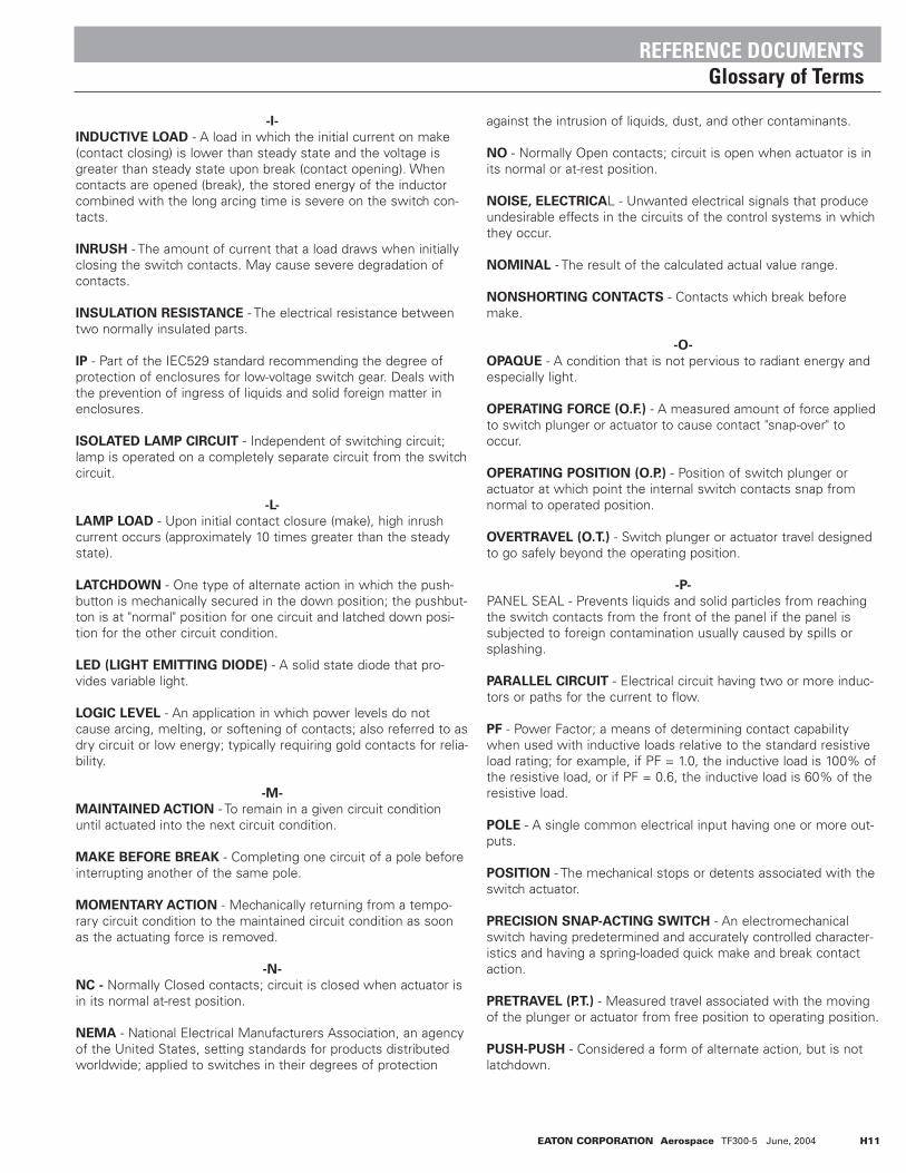
-I-
INDUCTIVE LOAD - A load in which the initial current on make(contact closing) is lower than steady state and the voltage isgreater than steady state upon break (contact opening). Whencontacts are opened (break), the stored energy of the inductorcombined with the long arcing time is severe on the switch con-tacts.
INRUSH - The amount of current that a load draws when initiallyclosing the switch contacts. May cause severe degradation ofcontacts.
INSULATION RESISTANCE - The electrical resistance betweentwo normally insulated parts.
IP - Part of the IEC529 standard recommending the degree ofprotection of enclosures for low-voltage switch gear. Deals withthe prevention of ingress of liquids and solid foreign matter inenclosures.
ISOLATED LAMP CIRCUIT - Independent of switching circuit;lamp is operated on a completely separate circuit from the switchcircuit.
-L-
LAMP LOAD - Upon initial contact closure (make), high inrushcurrent occurs (approximately 10 times greater than the steadystate).
LATCHDOWN - One type of alternate action in which the push-button is mechanically secured in the down position; the pushbut-ton is at "normal" position for one circuit and latched down posi-tion for the other circuit condition.
LED (LIGHT EMITTING DIODE) - A solid state diode that pro-vides variable light.
LOGIC LEVEL - An application in which power levels do notcause arcing, melting, or softening of contacts; also referred to asdry circuit or low energy; typically requiring gold contacts for relia-bility.
-M-
MAINTAINED ACTION - To remain in a given circuit conditionuntil actuated into the next circuit condition.
MAKE BEFORE BREAK - Completing one circuit of a pole beforeinterrupting another of the same pole.
MOMENTARY ACTION - Mechanically returning from a tempo-rary circuit condition to the maintained circuit condition as soonas the actuating force is removed.
-N-
NC - Normally Closed contacts; circuit is closed when actuator isin its normal at-rest position.
NEMA - National Electrical Manufacturers Association, an agencyof the United States, setting standards for products distributedworldwide; applied to switches in their degrees of protection
against the intrusion of liquids, dust, and other contaminants.
NO - Normally Open contacts; circuit is open when actuator is inits normal or at-rest position.
NOISE, ELECTRICAL - Unwanted electrical signals that produceundesirable effects in the circuits of the control systems in whichthey occur.
NOMINAL - The result of the calculated actual value range.
NONSHORTING CONTACTS - Contacts which break beforemake.
-O-
OPAQUE - A condition that is not pervious to radiant energy andespecially light.
OPERATING FORCE (O.F.) - A measured amount of force appliedto switch plunger or actuator to cause contact "snap-over" tooccur.
OPERATING POSITION (O.P.) - Position of switch plunger oractuator at which point the internal switch contacts snap fromnormal to operated position.
OVERTRAVEL (O.T.) - Switch plunger or actuator travel designedto go safely beyond the operating position.
-P-
PANEL SEAL - Prevents liquids and solid particles from reachingthe switch contacts from the front of the panel if the panel issubjected to foreign contamination usually caused by spills orsplashing.
PARALLEL CIRCUIT - Electrical circuit having two or more induc-tors or paths for the current to flow.
PF - Power Factor; a means of determining contact capabilitywhen used with inductive loads relative to the standard resistiveload rating; for example, if PF = 1.0, the inductive load is 100% ofthe resistive load, or if PF = 0.6, the inductive load is 60% of theresistive load.
POLE - A single common electrical input having one or more out-puts.
POSITION - The mechanical stops or detents associated with theswitch actuator.
PRECISION SNAP-ACTING SWITCH - An electromechanicalswitch having predetermined and accurately controlled character-istics and having a spring-loaded quick make and break contactaction.
PRETRAVEL (P.T.) - Measured travel associated with the movingof the plunger or actuator from free position to operating position.
PUSH-PUSH - Considered a form of alternate action, but is notlatchdown.
REFERENCE DOCUMENTSGlossary of Terms
EATON CORPORATION Aerospace TF300-5 June, 2004 H11

-R-
RELEASE FORCE (R.F.) - Amount of force still applied to switchplunger or actuator at moment contacts snap from operated posi-tion to unoperated position.
RMS - Root Mean Square.
-S-
SHORTING CONTACTS - Electrical switch contacts that aredesigned to make before break.
SILICONE RUBBER - Rubber produced from silicone elastomerswith a high amount of flexibility, resilience, and tensile strengthover a wide temperature range.
SNAP ACTION - Very fast mechanical transfer of contacts fromone position to another. Contact transfer action is independent ofspeed of actuator travel.
SPST - Single Pole Single Throw - see Pole; also Throw.
-T-
TACTILE FEEDBACK - The switching action felt by an operator ashe operates the switch from position to position.
THROW - The number of electrical circuits within a switch pole.
TOTAL TRAVEL - Combined distance of actuator pretravel andovertravel; total distance actuator moves from relaxed positionpast the point of electrical contact and to the end of travel.
TRANSLUCENT - Transmitting and diffusing light so that objectsbeyond cannot be seen clearly.
TRANSPARENT - Having the property of transmitting light with-out appreciably scattering so that objects lying beyond are entire-ly visible.
TRAVEL - The distance the switch actuator moves which causesa change of electrical circuits.
TWO CIRCUIT - Circuit in which one circuit is made in one posi-tion and a separate circuit is made in the other position.
-V-
VOLTAGE DROP - The difference of voltages at the two terminalsof a passive impedance.
-W-
WIPING ACTION - The action caused by the movable switch con-tact sliding across the stationary contact, resulting in the cleaningof the contact surfaces.
REFERENCE DOCUMENTSGlossary of Terms
H12 EATON CORPORATION Aerospace TF300-5 June, 2004
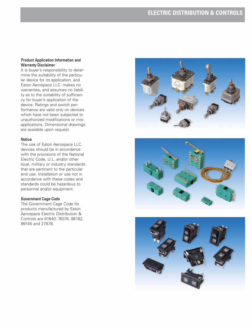
PPrroodduucctt AApppplliiccaattiioonn IInnffoorrmmaattiioonn aannddWWaarrrraannttyy DDiissccllaaiimmeerrIt is buyer’s responsibility to deter-mine the suitability of the particu-lar device for its application, andEaton Aerospace LLC. makes nowarranties, and assumes no liabili-ty as to the suitability of sufficien-cy for buyer’s application of thedevice. Ratings and switch per-formance are valid only on deviceswhich have not been subjected tounauthorized modifications or mis-applications. Dimensional drawingsare available upon request.
NNoottiicceeThe use of Eaton Aerospace LLC.devices should be in accordancewith the provisions of the NationalElectric Code, U.L. and/or otherlocal, military or industry standardsthat are pertinent to the particularend use. Installation or use not inaccordance with these codes andstandards could be hazardous topersonnel and/or equipment.
GGoovveerrnnmmeenntt CCaaggee CCooddeeThe Government Cage Code forproducts manufactured by EatonAerospace Electric Distribution &Controls are 81640, 76374, 96182,99145 and 27878.
ELECTRIC DISTRIBUTION & CONTROLS

©2004 Eaton CorporationAll Rights ReservedPrinted In USACopying or Editing is ForbiddenTF300-5June, 2004
Eaton CorporationElectric Distribution & Controls
2250 Whitfield AvenueSarasota, FL 34243Tel: (800) 955-7354 / (941) 751-7138Fax: (941) 751-7173www.aerospace.eaton.com