eh27401 communication and control in electric power ... · assume 25 kva trafo 5 loads per...
TRANSCRIPT
1
EH27401 Communication and Control in
Electric Power Systems Lecture 2
Lars Nordström [email protected]
2
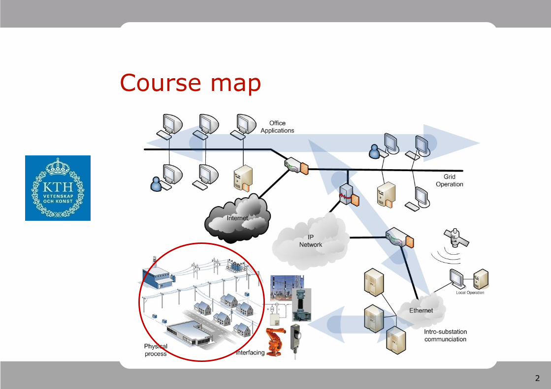
Course map
3
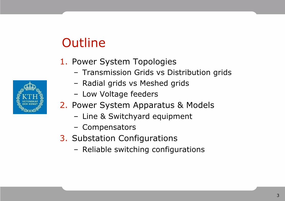
Outline 1. Power System Topologies
– Transmission Grids vs Distribution grids – Radial grids vs Meshed grids – Low Voltage feeders
2. Power System Apparatus & Models – Line & Switchyard equipment – Compensators
3. Substation Configurations – Reliable switching configurations
4
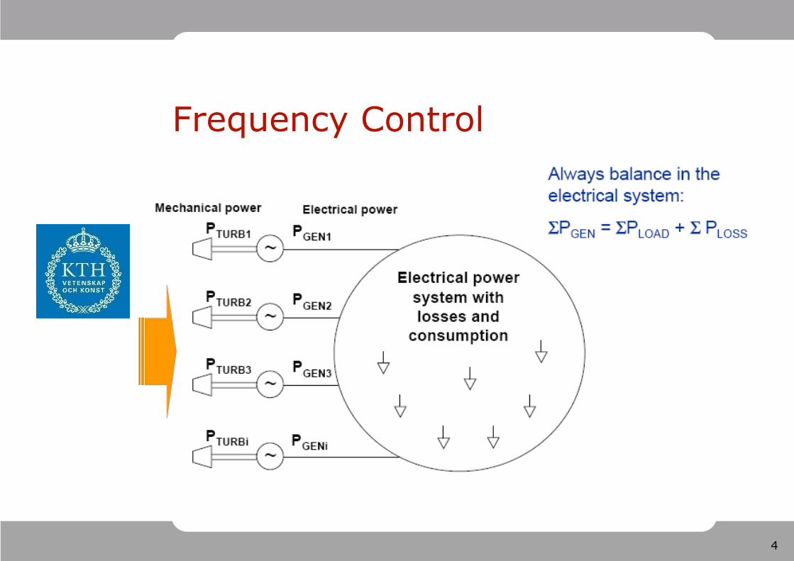
Frequency Control
5
Tools for Voltage Control Main goal is to keep an even voltage profile. Generators with automatic voltage regulator (AVR)
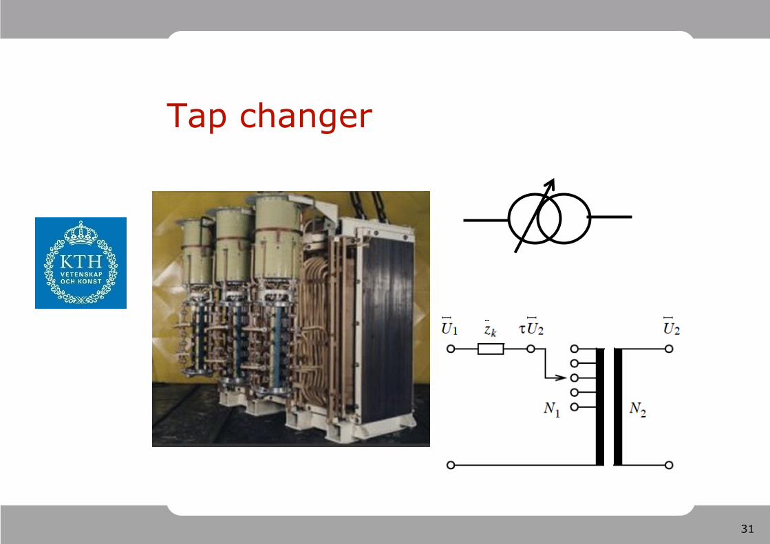
control voltage at generator bus Transformers with tapchanger. Step-wise control of
voltage at one side Shunt reactors consume reactive power, which
decreases the voltage Shunt capacitors produce reactive power, which
increases the voltage Shunt compensation can be controlled
– manually (from the control room) – with voltage automatic control – with time control – by a centralised logic
6
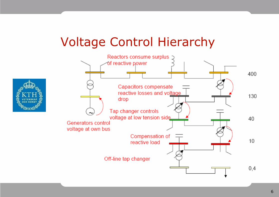
Voltage Control Hierarchy
7
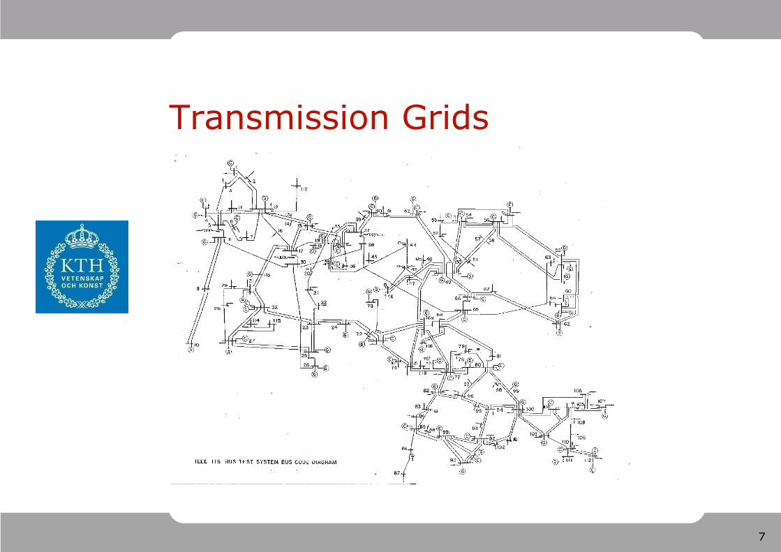
Transmission Grids

8
Meshed MV Grid
9
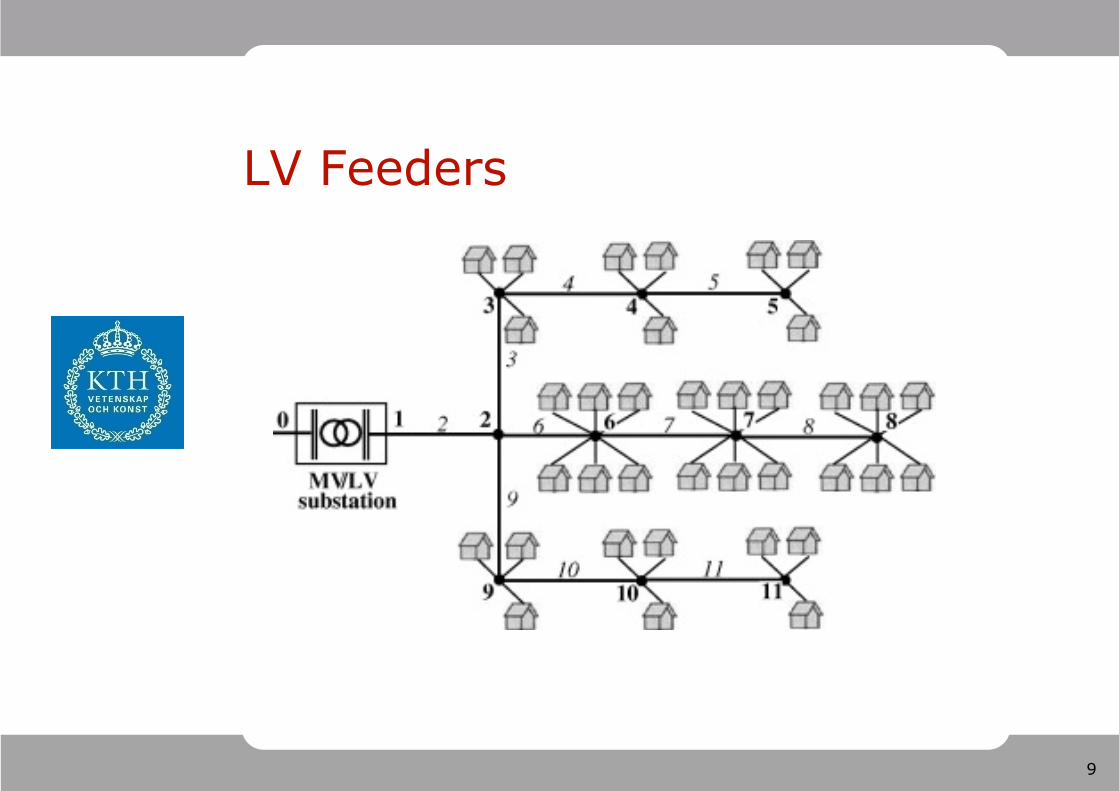
LV Feeders
10
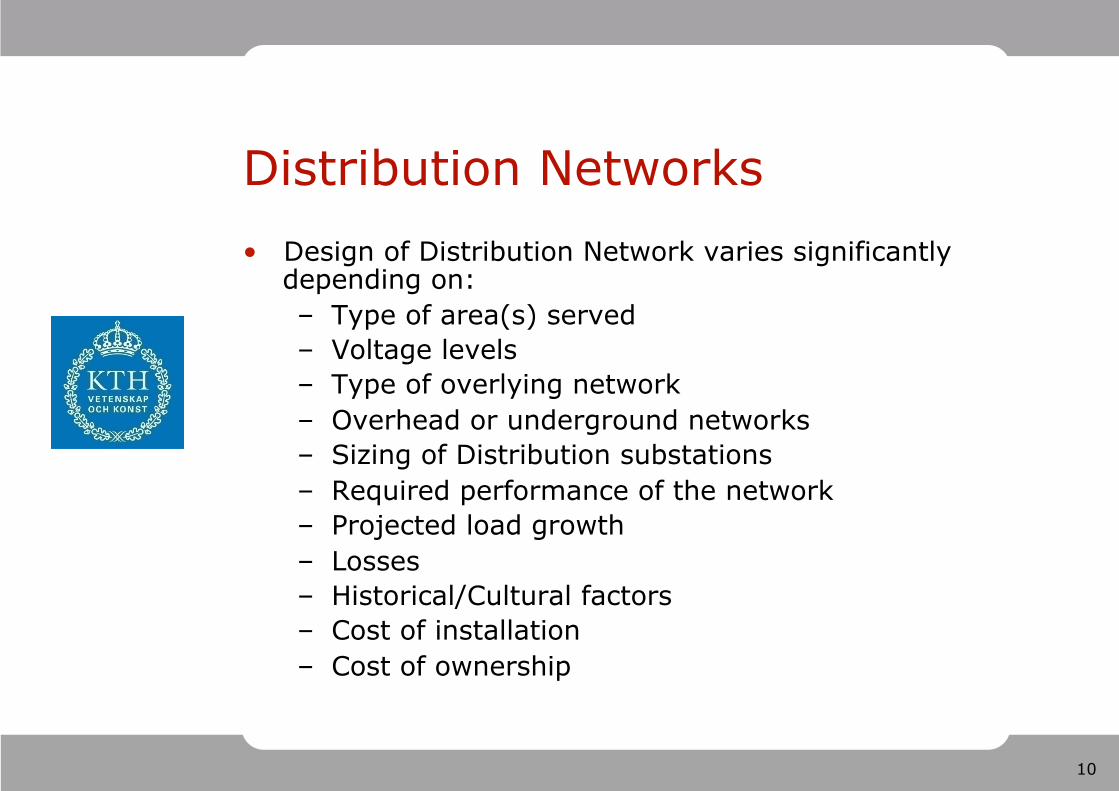
Distribution Networks Design of Distribution Network varies significantly
depending on: – Type of area(s) served – Voltage levels – Type of overlying network – Overhead or underground networks – Sizing of Distribution substations – Required performance of the network – Projected load growth – Losses – Historical/Cultural factors – Cost of installation – Cost of ownership
11
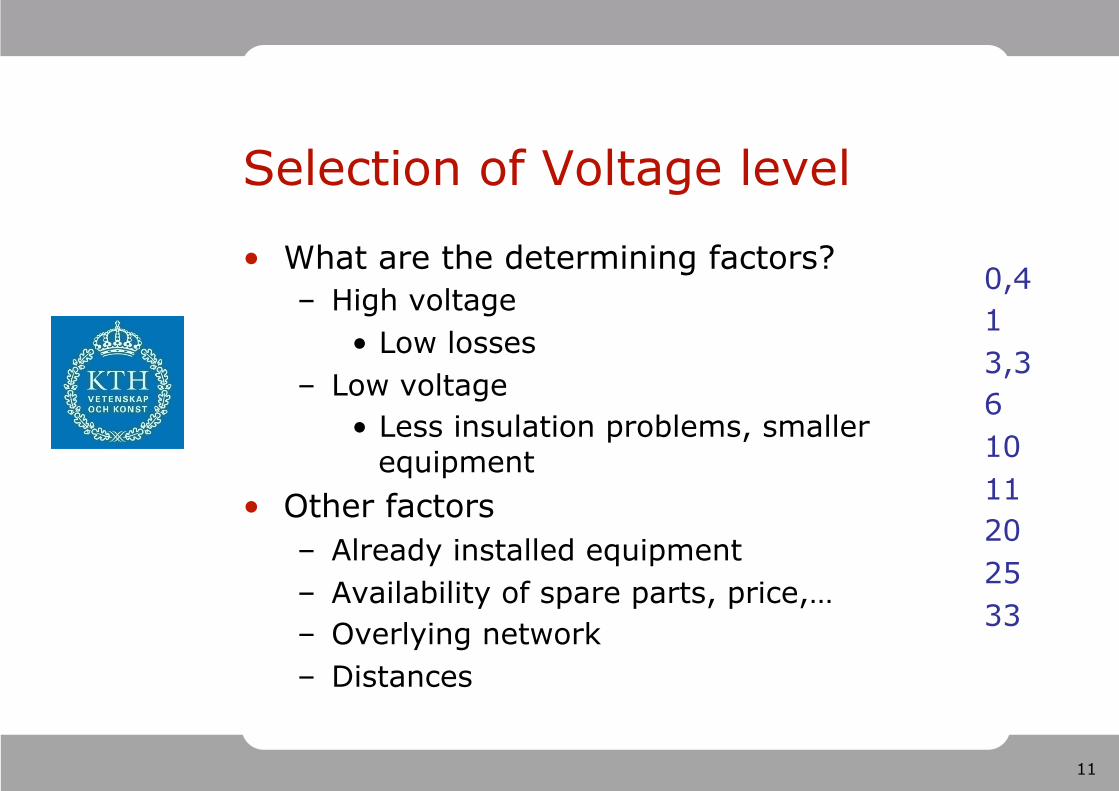
Selection of Voltage level
What are the determining factors? – High voltage
Low losses – Low voltage
Less insulation problems, smaller equipment
Other factors – Already installed equipment – Availability of spare parts, price,… – Overlying network – Distances
0,4 1 3,3 6 10 11 20 25 33
12
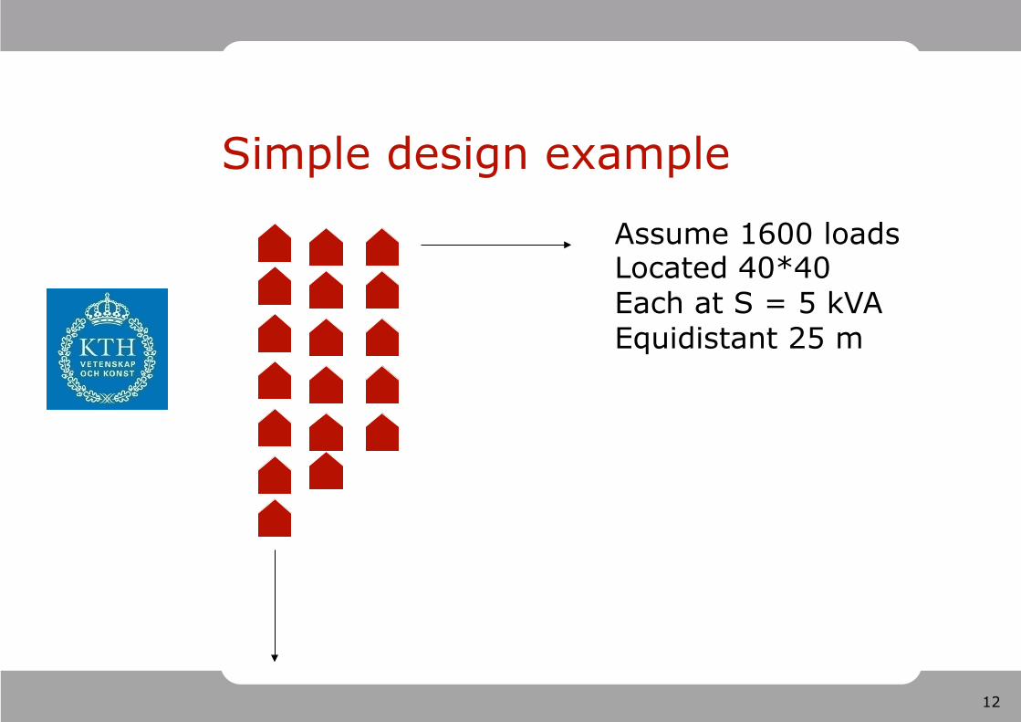
Simple design example
Assume 1600 loads Located 40*40 Each at S = 5 kVA Equidistant 25 m
13
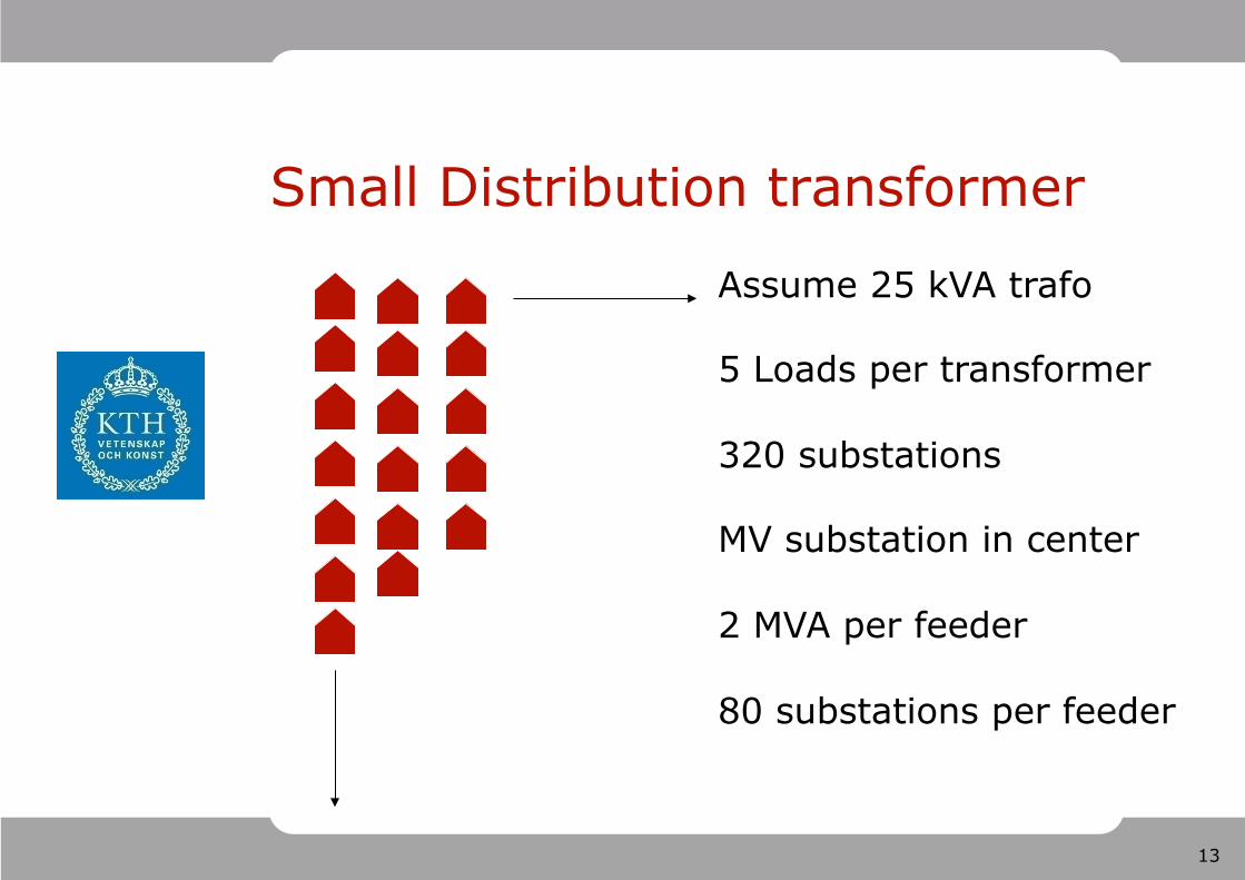
Small Distribution transformer
Assume 25 kVA trafo 5 Loads per transformer 320 substations MV substation in center 2 MVA per feeder 80 substations per feeder
14
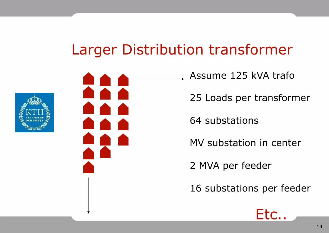
Larger Distribution transformer
Assume 125 kVA trafo 25 Loads per transformer 64 substations MV substation in center 2 MVA per feeder 16 substations per feeder
Etc..
15
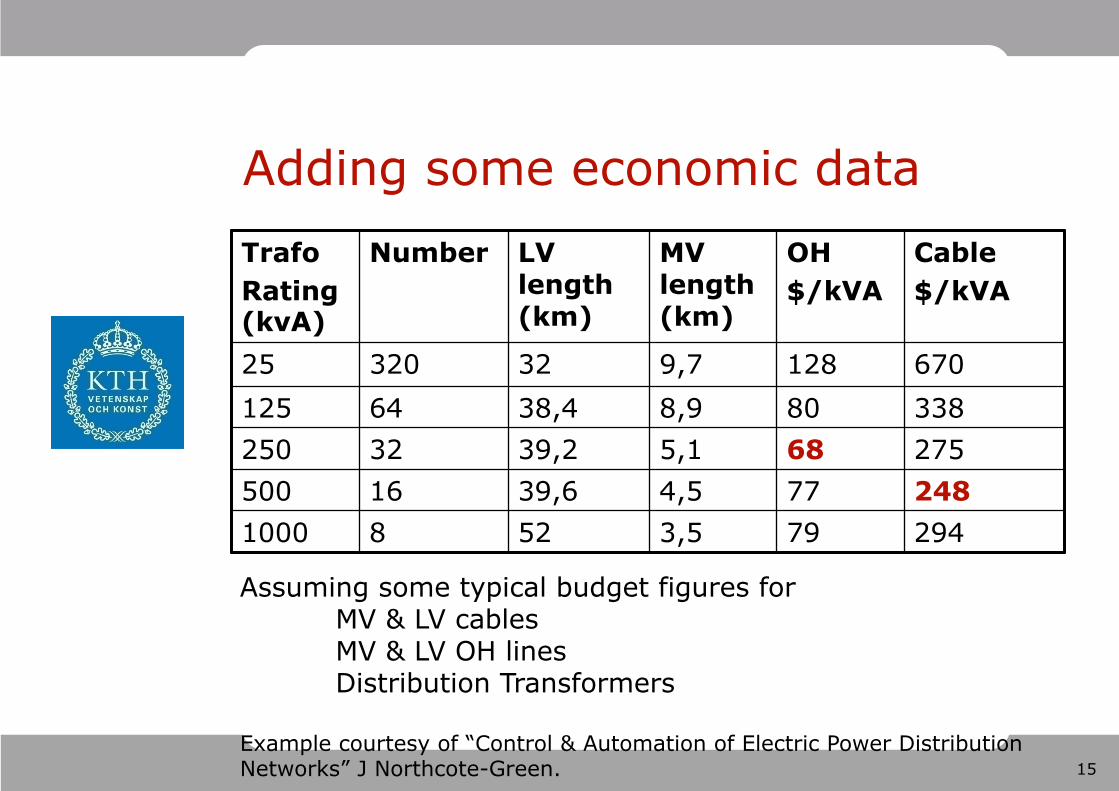
Adding some economic data Trafo Rating (kvA)
Number LV length (km)
MV length (km)
OH $/kVA
Cable $/kVA
25 320 32 9,7 128 670 125 64 38,4 8,9 80 338 250 32 39,2 5,1 68 275 500 16 39,6 4,5 77 248 1000 8 52 3,5 79 294
Assuming some typical budget figures for MV & LV cables MV & LV OH lines Distribution Transformers
Example courtesy of “Control & Automation of Electric Power Distribution Networks” J Northcote-Green.
16
Additional concerns
In addition to cost of building and operating the distribution network, the reliability of the network is essential.
A number of indices are used to determine the quality of service delivered.
Additionally, regulators specify levels of quality and or cost caps that the distribution company must follow or be fined.
17
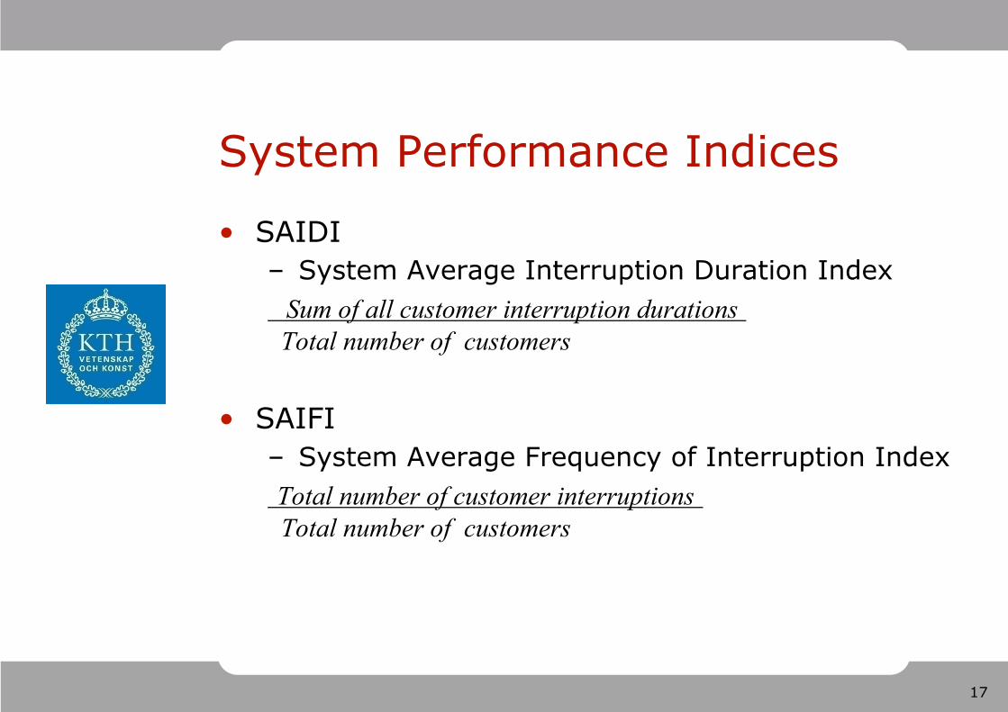
System Performance Indices
SAIDI – System Average Interruption Duration Index Sum of all customer interruption durations Total number of customers
SAIFI – System Average Frequency of Interruption Index Total number of customer interruptions Total number of customers
18
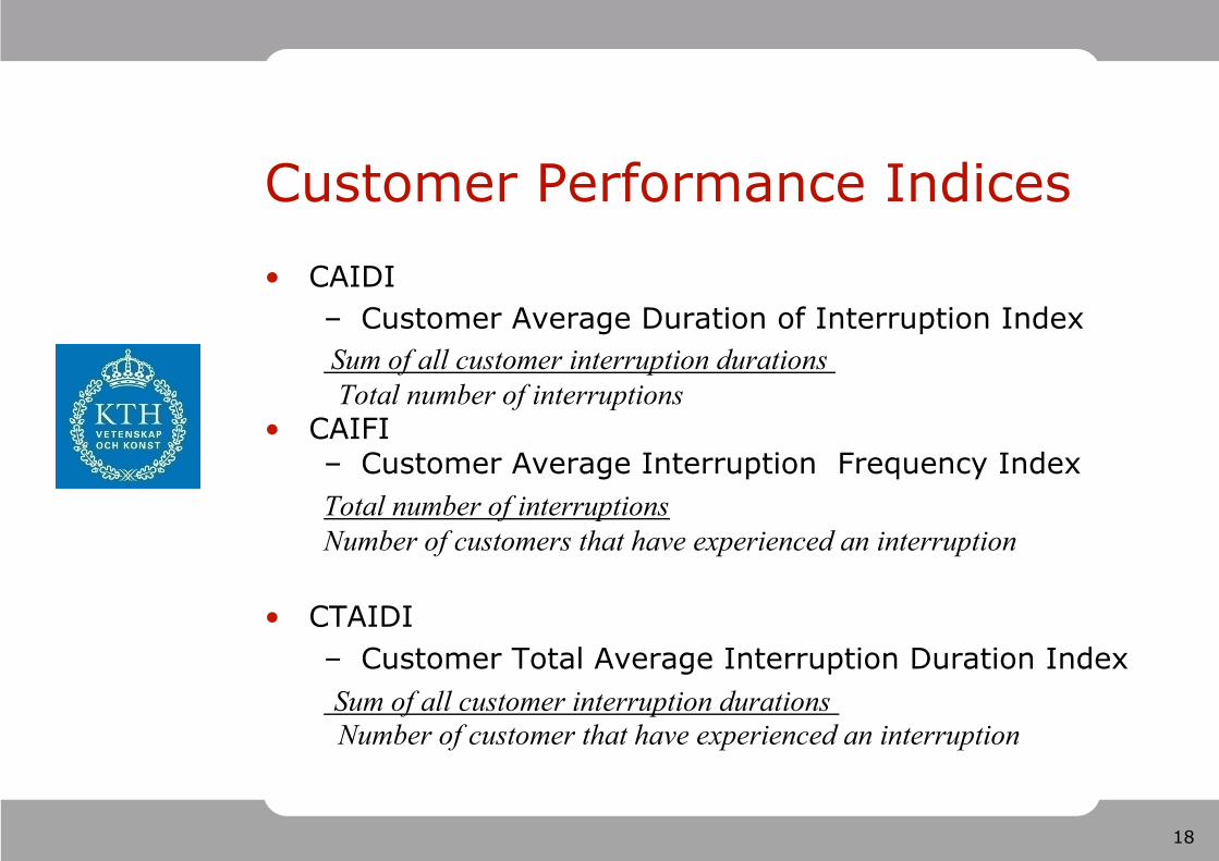
Customer Performance Indices CAIDI
– Customer Average Duration of Interruption Index Sum of all customer interruption durations Total number of interruptions
CAIFI – Customer Average Interruption Frequency Index Total number of interruptions Number of customers that have experienced an interruption
CTAIDI – Customer Total Average Interruption Duration Index Sum of all customer interruption durations Number of customer that have experienced an interruption
19
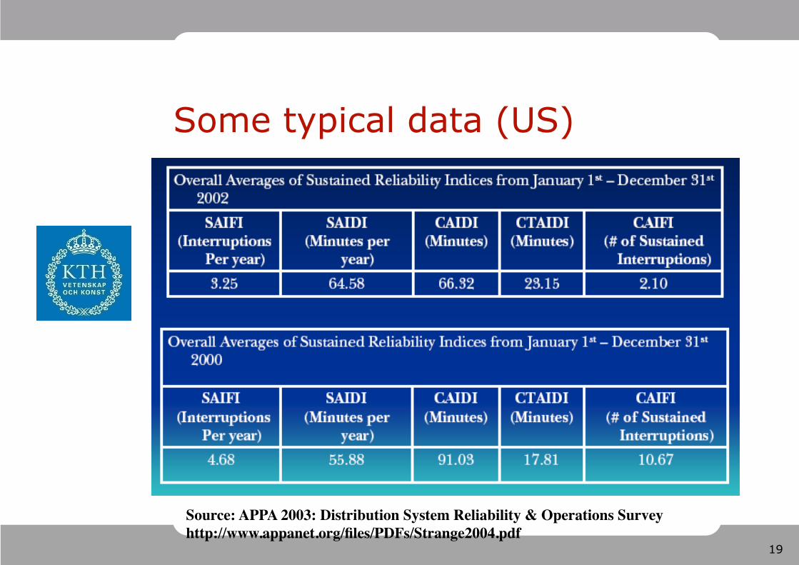
Some typical data (US)
Source: APPA 2003: Distribution System Reliability & Operations Survey
20
Main challenge for DSOs
Designing and operating a distribution network at low cost while maintaining high level of reliability
21
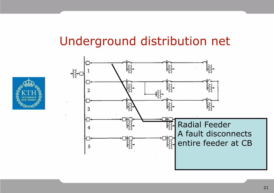
Underground distribution net
Radial Feeder A fault disconnects entire feeder at CB
22
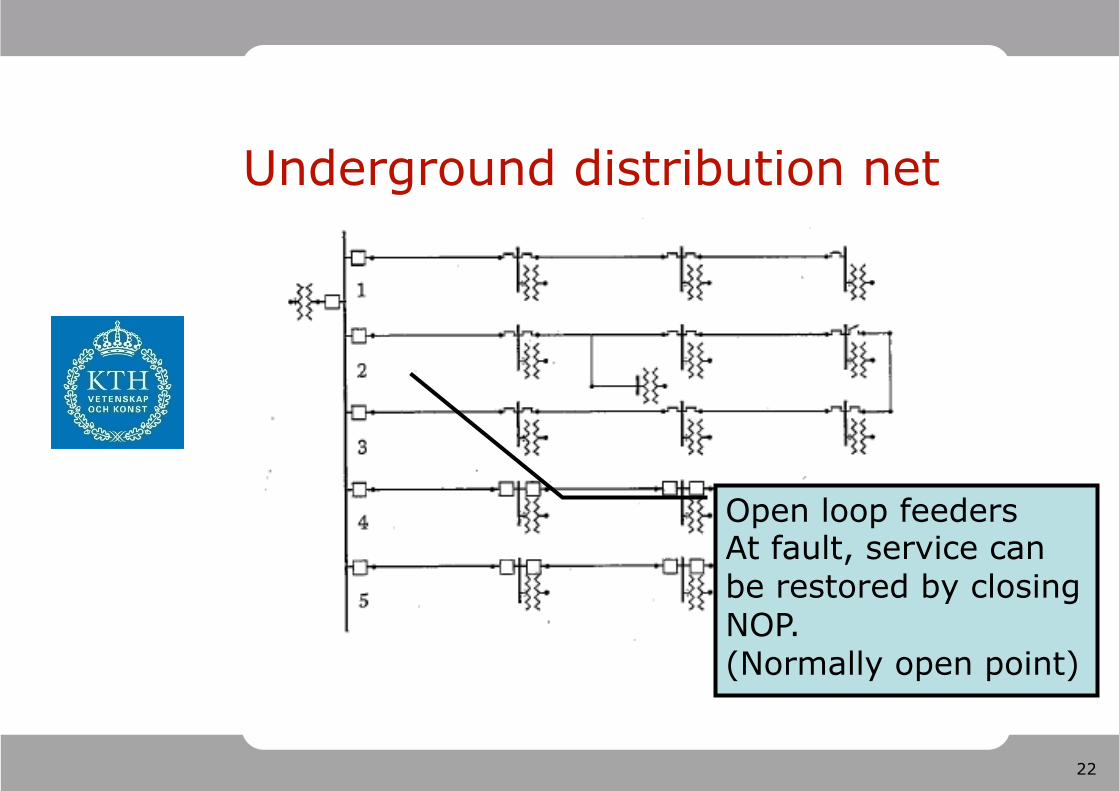
Underground distribution net
Open loop feeders At fault, service can be restored by closing NOP. (Normally open point)
23
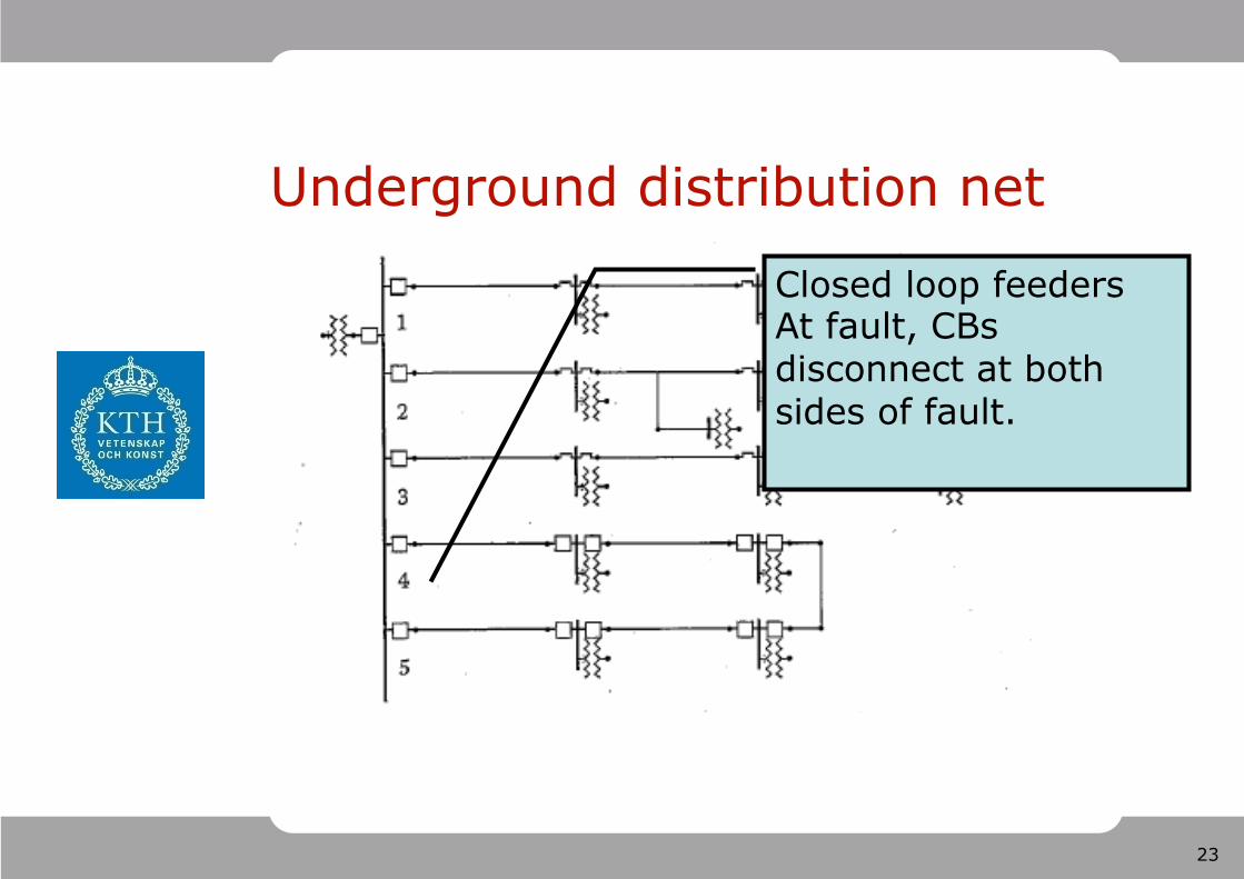
Underground distribution net
Closed loop feeders At fault, CBs disconnect at both sides of fault.
24
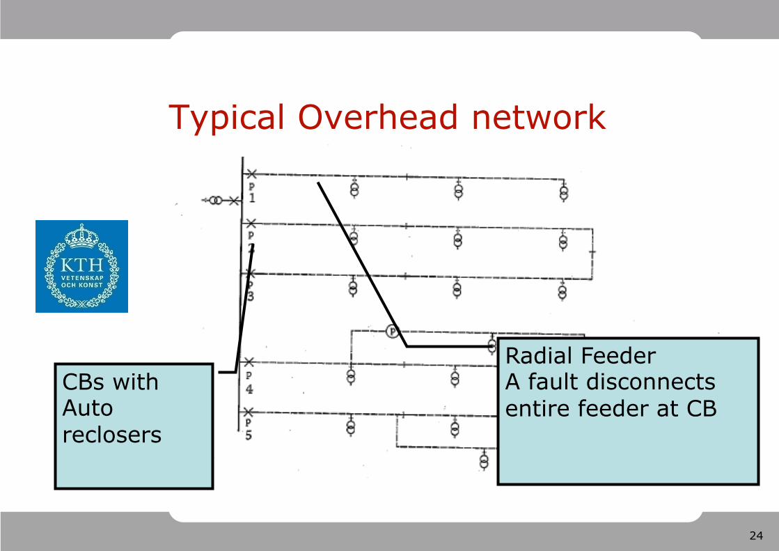
Typical Overhead network
Radial Feeder A fault disconnects entire feeder at CB
CBs with Auto reclosers
25
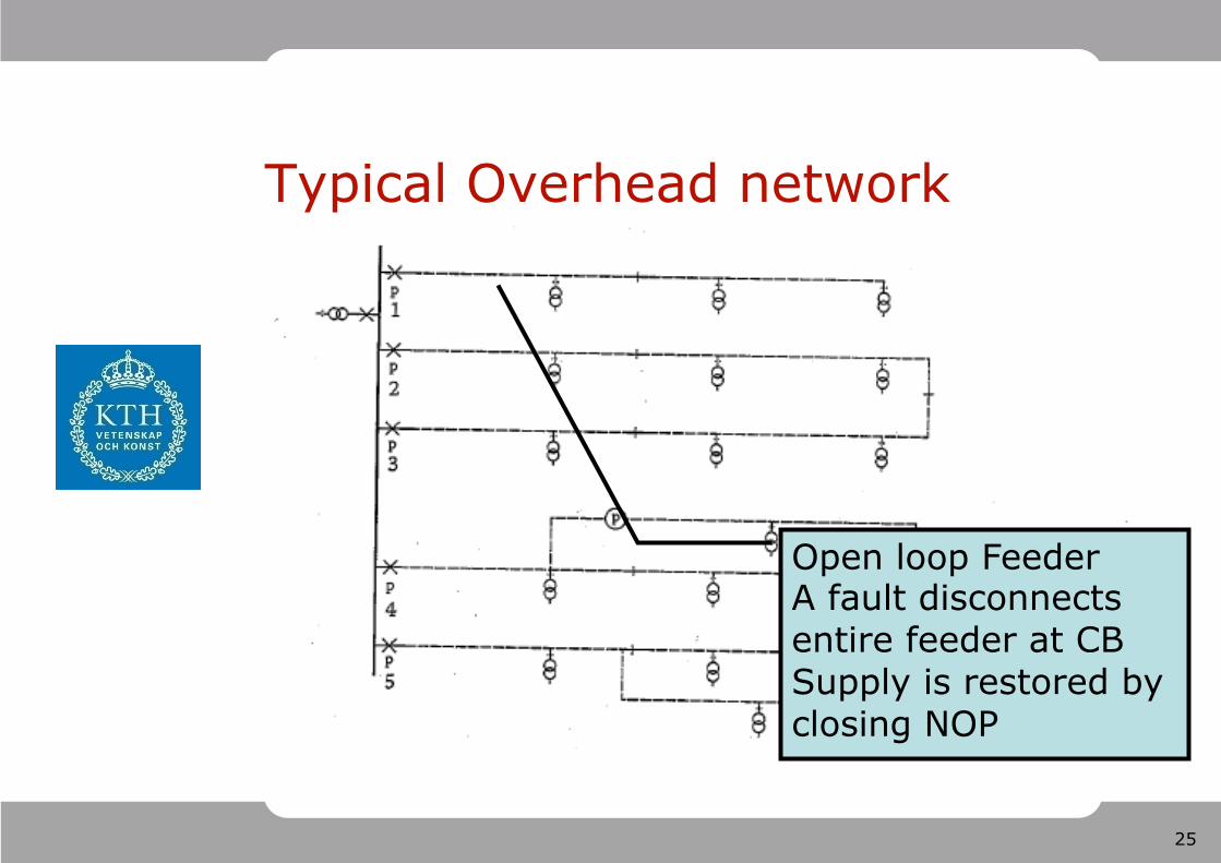
Typical Overhead network
Open loop Feeder A fault disconnects entire feeder at CB Supply is restored by closing NOP
26
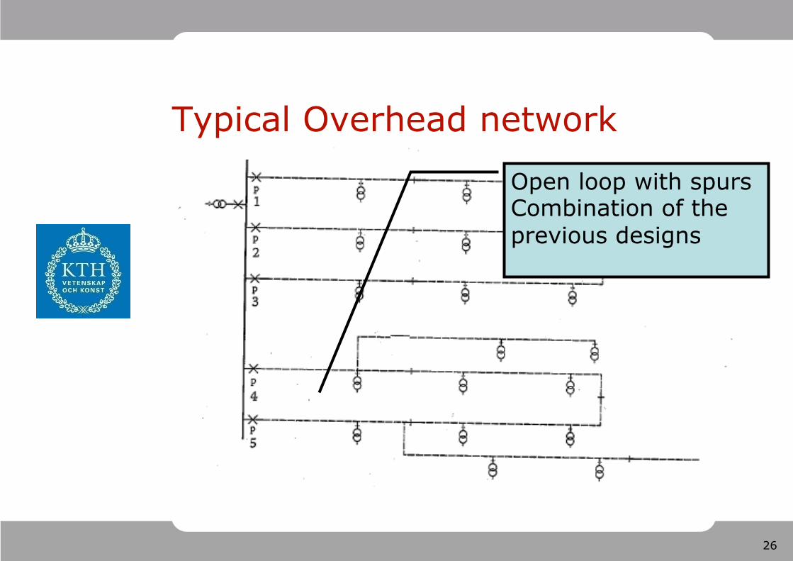
Typical Overhead network
Open loop with spurs Combination of the previous designs
27
Outline 1. Power System Topologies
– Transmission Grids vs Distribution grids – Radial grids vs Meshed grids – Low Voltage feeders
2. Power System Apparatus & Models – Line & Switchyard equipment – Compensators
3. Substation Configurations – Reliable switching configurations
28
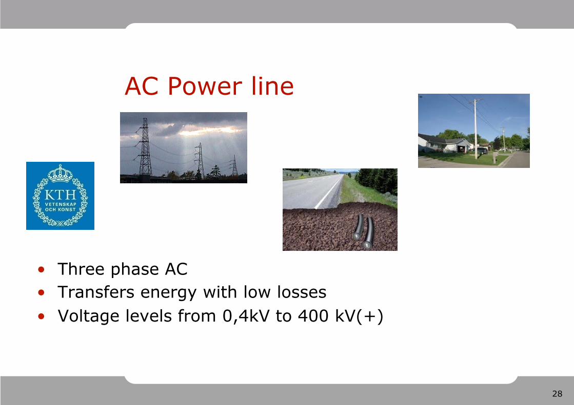
AC Power line
Three phase AC Transfers energy with low losses Voltage levels from 0,4kV to 400 kV(+)
29
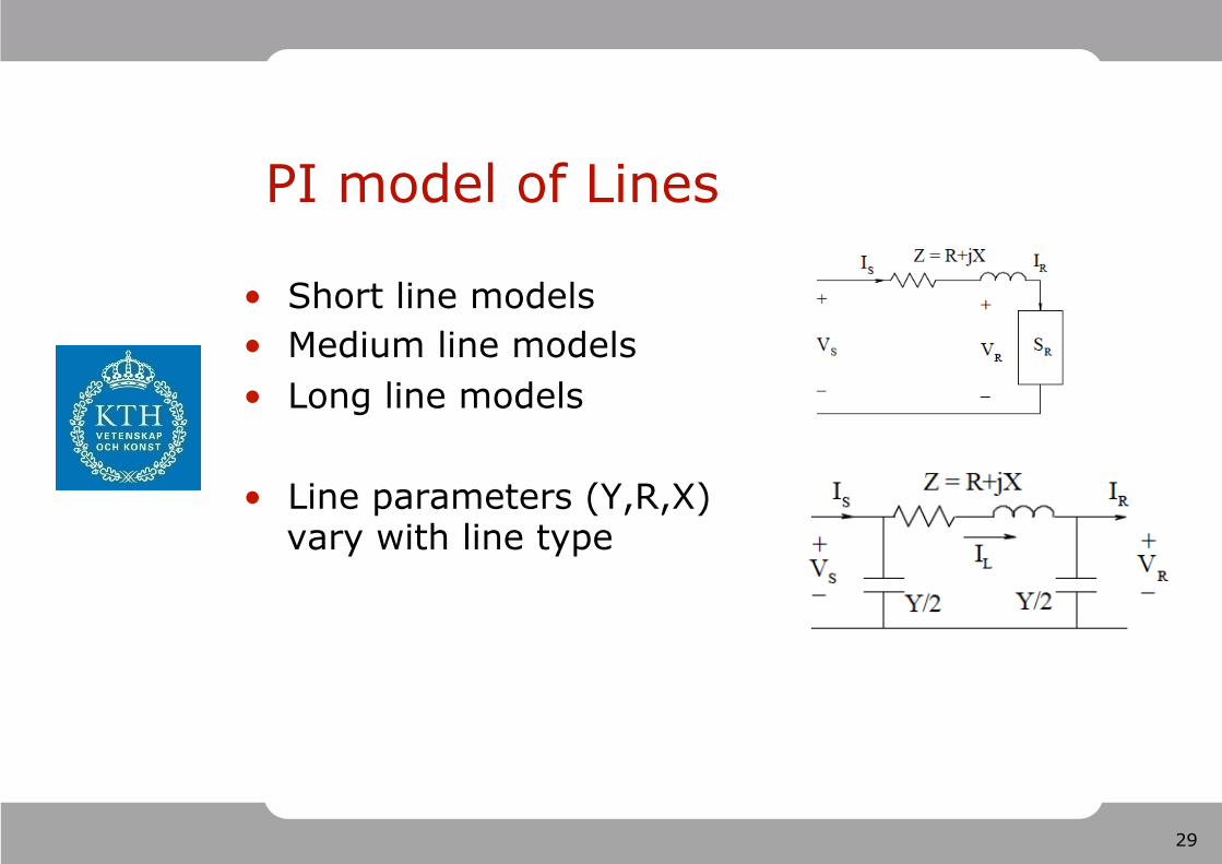
PI model of Lines
Short line models Medium line models Long line models
Line parameters (Y,R,X) vary with line type
30
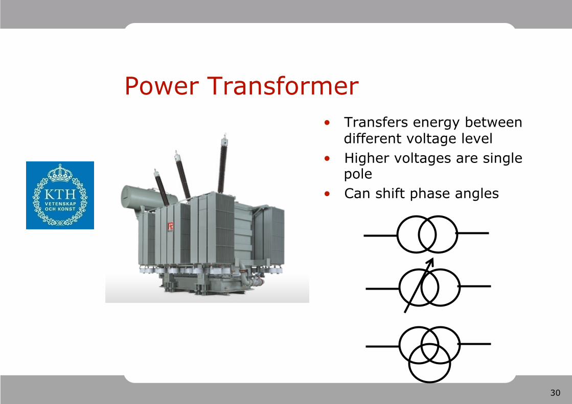
Power Transformer Transfers energy between
different voltage level Higher voltages are single
pole Can shift phase angles
31
Tap changer
32
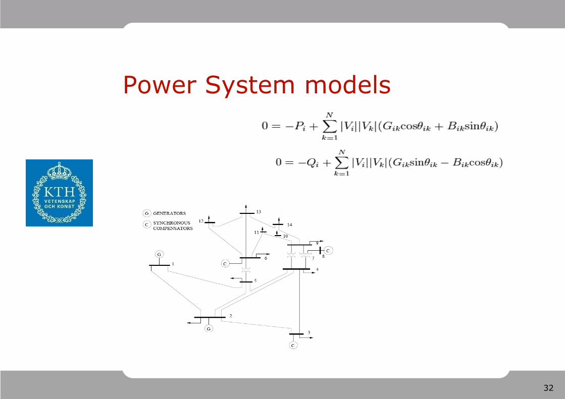
Power System models
33
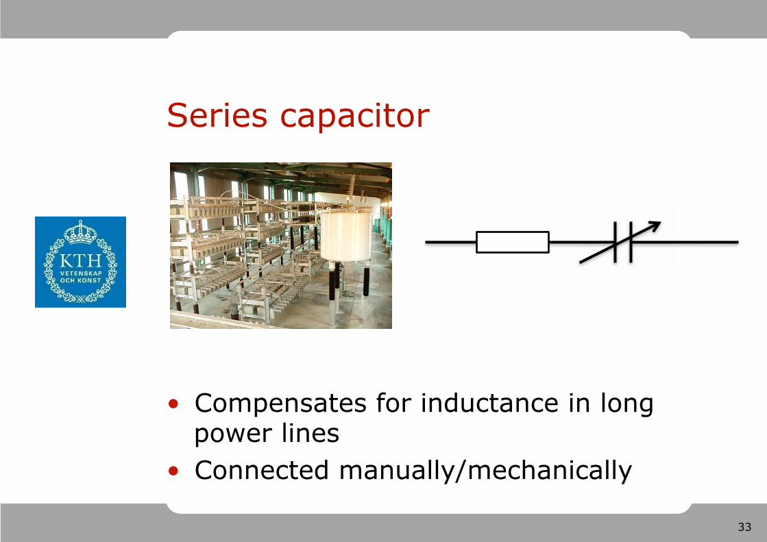
Series capacitor
Compensates for inductance in long power lines Connected manually/mechanically
34
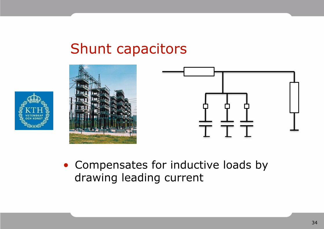
Shunt capacitors
Compensates for inductive loads by drawing leading current
35
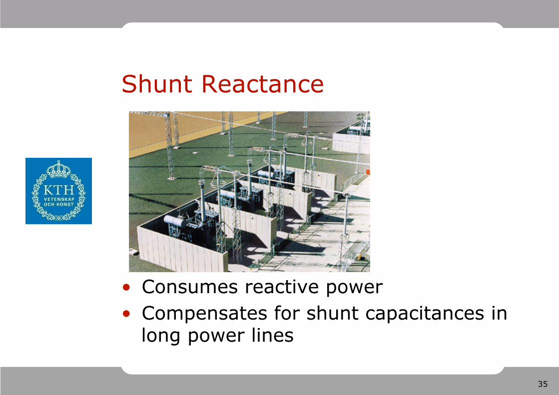
Shunt Reactance
Consumes reactive power Compensates for shunt capacitances in long power lines
36
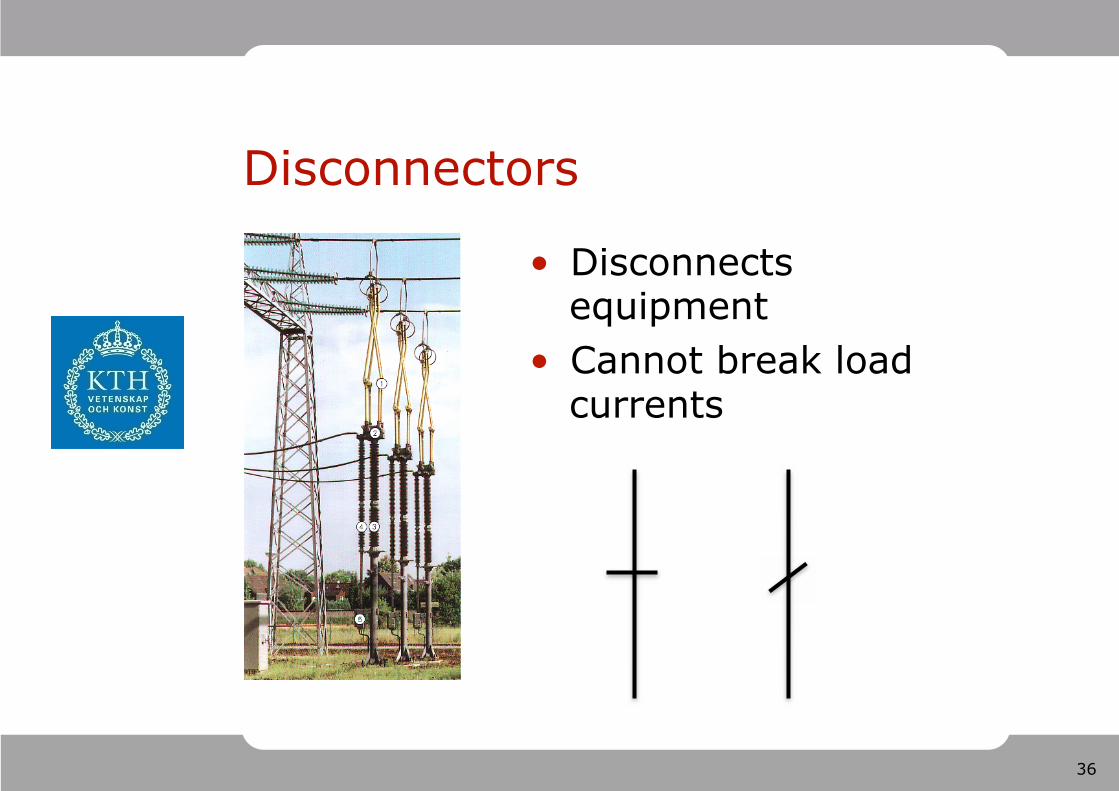
Disconnectors
Disconnects equipment Cannot break load currents
37
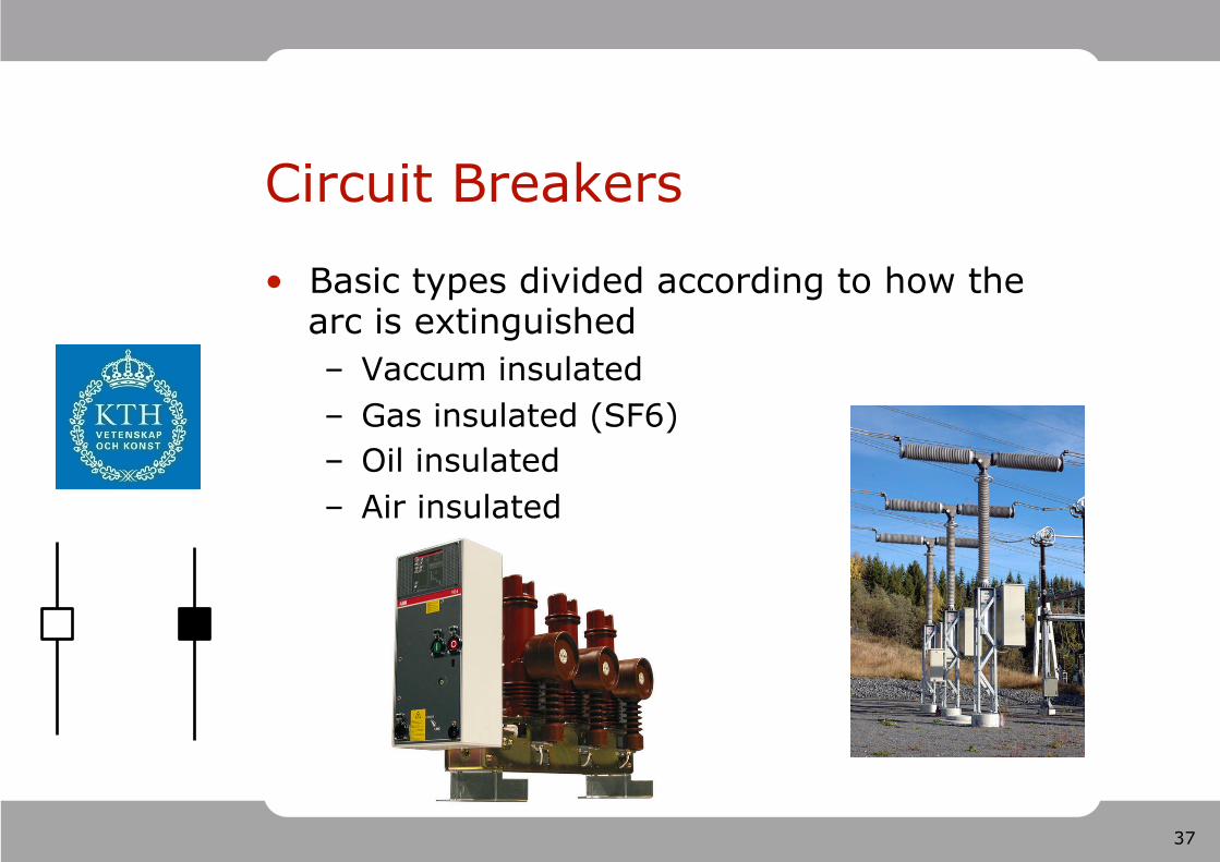
Circuit Breakers
Basic types divided according to how the arc is extinguished – Vaccum insulated – Gas insulated (SF6) – Oil insulated – Air insulated
38
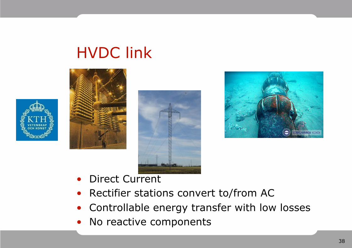
HVDC link
Direct Current Rectifier stations convert to/from AC Controllable energy transfer with low losses No reactive components
39
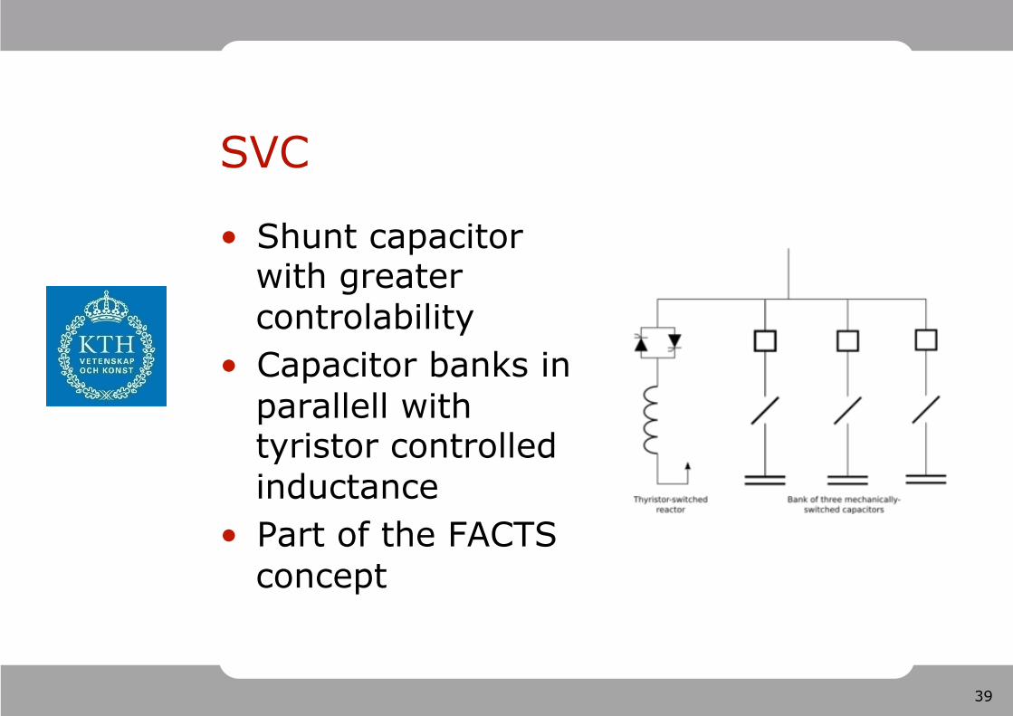
SVC
Shunt capacitor with greater controlability Capacitor banks in parallell with tyristor controlled inductance Part of the FACTS concept
40
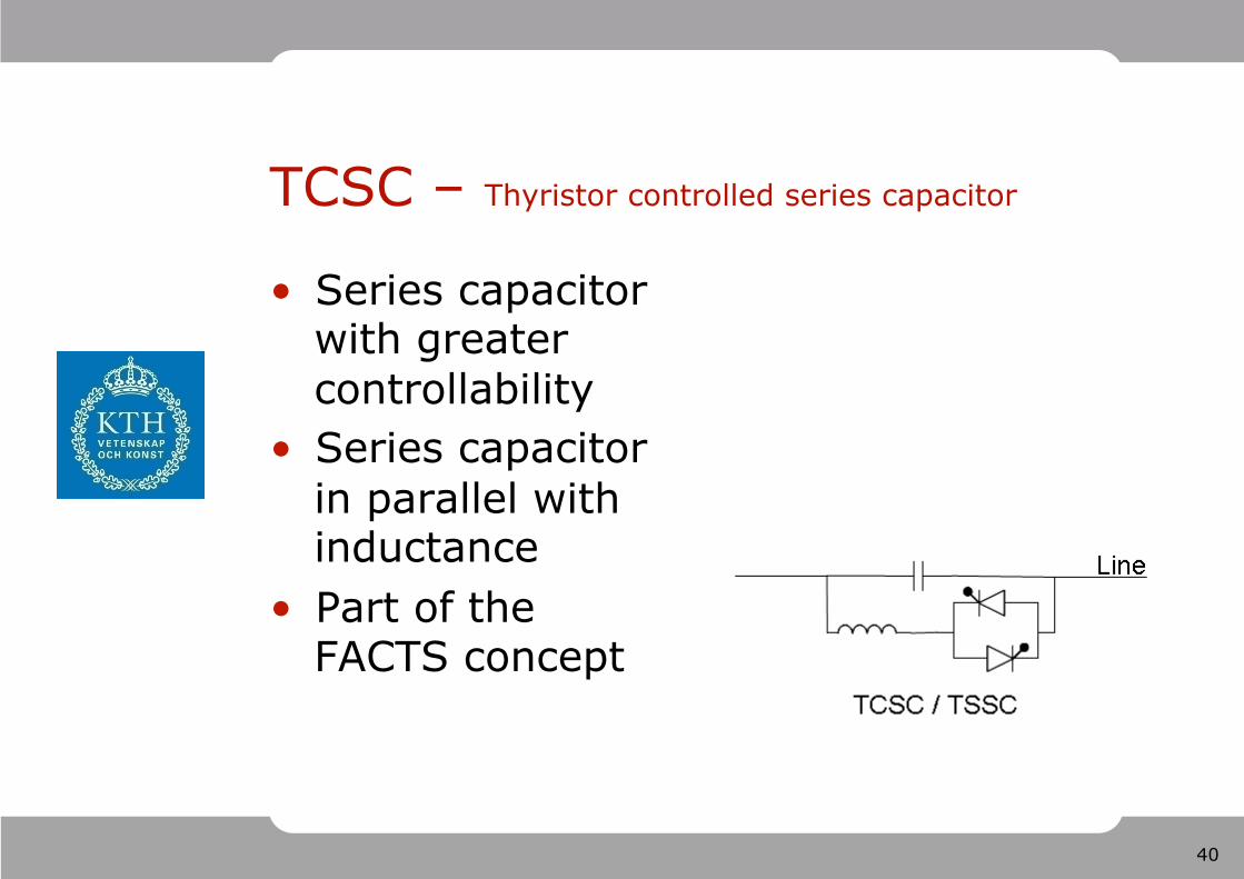
TCSC – Thyristor controlled series capacitor
Series capacitor with greater controllability Series capacitor in parallel with inductance Part of the FACTS concept
41
Outline 1. Power System Topologies
– Transmission Grids vs Distribution grids – Radial grids vs Meshed grids – Low Voltage feeders
2. Power System Apparatus & Models – Line & Switchyard equipment – Compensators – Generating equipment
3. Substation Configurations – Reliable switching configurations
42
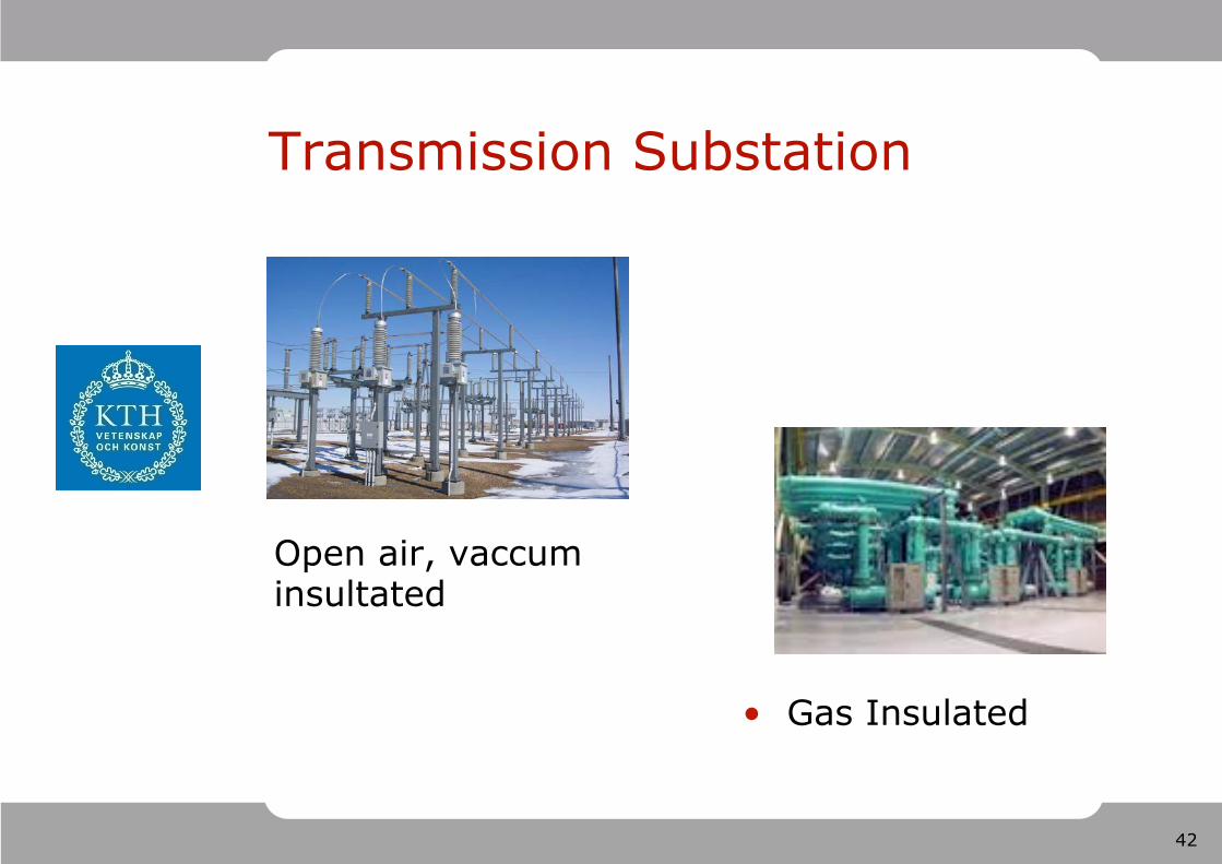
Transmission Substation
Gas Insulated
Open air, vaccum insultated
43
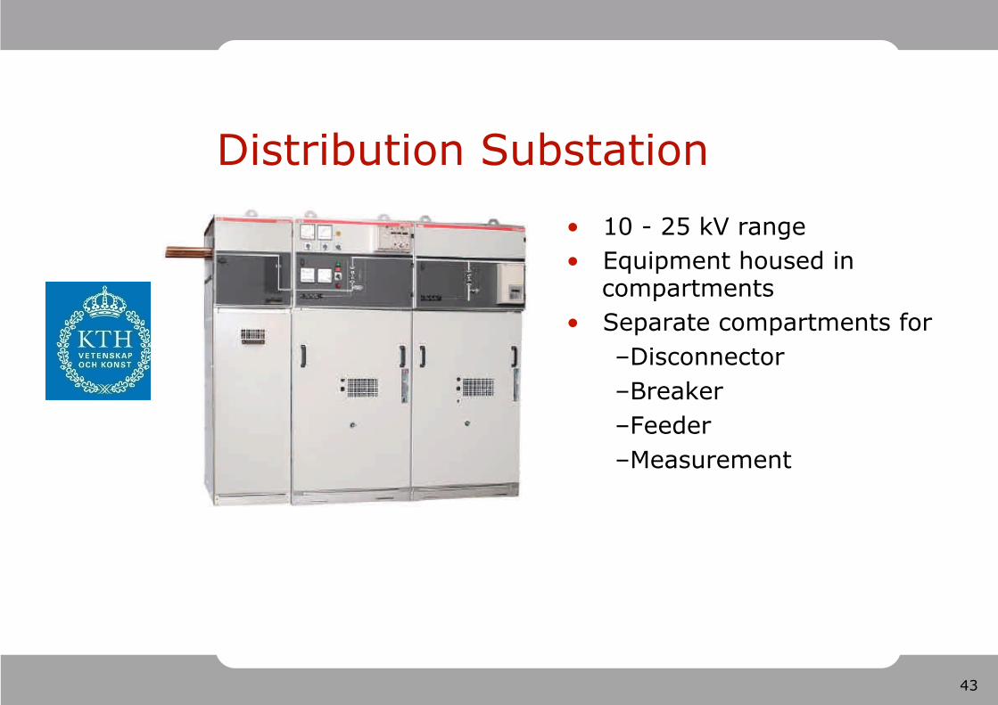
Distribution Substation 10 - 25 kV range Equipment housed in
compartments Separate compartments for
– Disconnector – Breaker – Feeder – Measurement
44
45
Evaluation Criteria
Reliability Operation Flexibility Maintenance Flexibility Costs

46
Single Bus Configuration
47
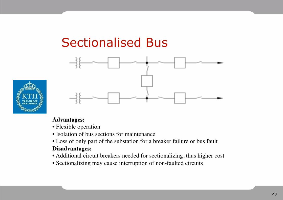
Sectionalised Bus
48
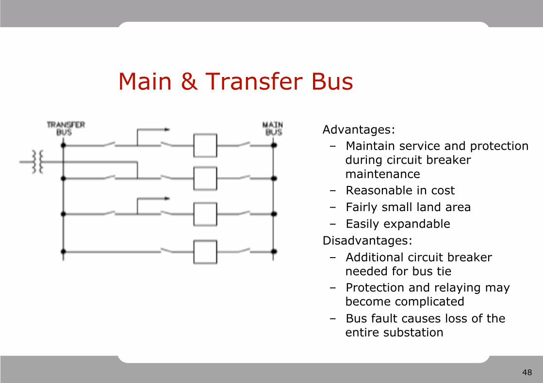
Main & Transfer Bus
Advantages: – Maintain service and protection
during circuit breaker maintenance
– Reasonable in cost – Fairly small land area – Easily expandable
Disadvantages: – Additional circuit breaker
needed for bus tie – Protection and relaying may
become complicated – Bus fault causes loss of the
entire substation
49
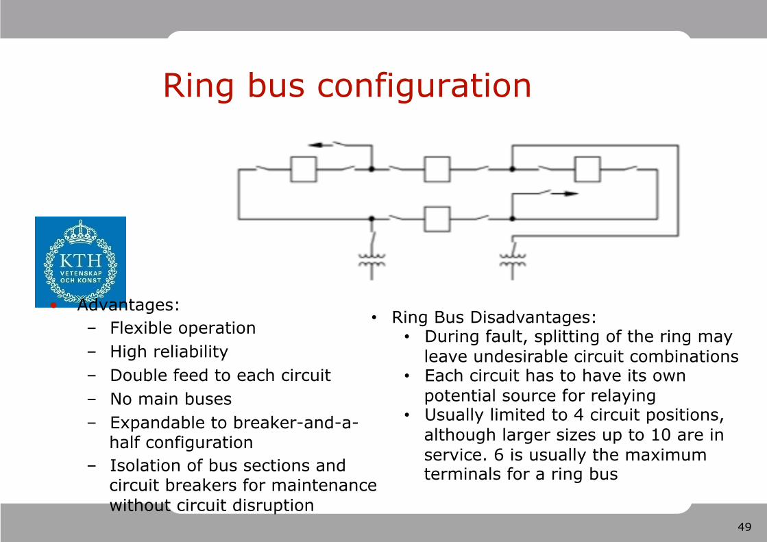
Ring bus configuration
Advantages: – Flexible operation – High reliability – Double feed to each circuit – No main buses – Expandable to breaker-and-a-
half configuration – Isolation of bus sections and
circuit breakers for maintenance without circuit disruption
Ring Bus Disadvantages: During fault, splitting of the ring may
leave undesirable circuit combinations Each circuit has to have its own
potential source for relaying Usually limited to 4 circuit positions,
although larger sizes up to 10 are in service. 6 is usually the maximum terminals for a ring bus
50
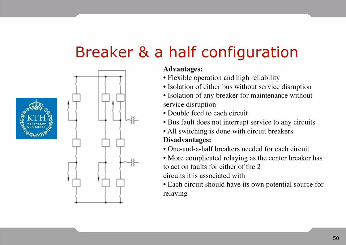
Breaker & a half configuration
51
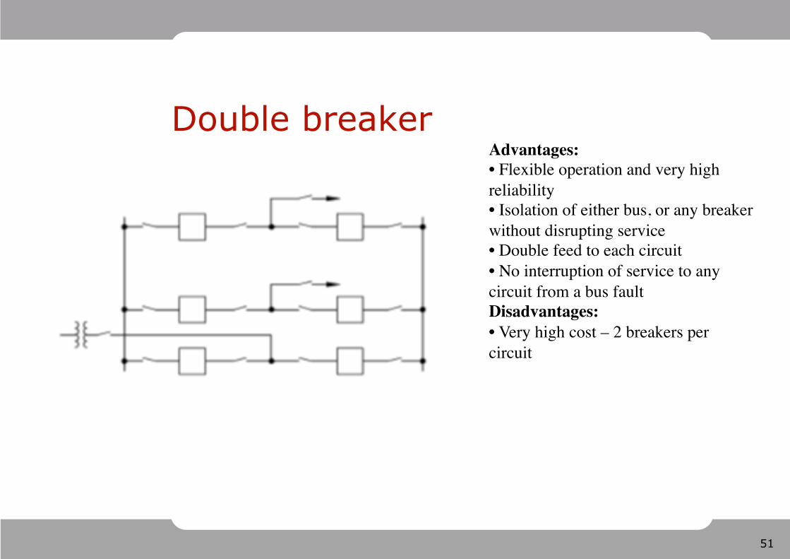
Double breaker

52
Questions or comments?