efficiently determination of the heat exchanger...
TRANSCRIPT

EFFICIENTLY DETERMINATION OF THE
HEAT EXCHANGER RTCF 200 kW FOR
ELECTRIC POWER TRANSFORMERS
USING THE FINITE ELEMENT METHOD
M. BICĂ1
M. IOLU 2 Ş. IOLU
3
Abstract: This paper presents the results of analysis using finite element
method with aid of FLUENT 6.3.26 programme concerning the efficiency of
heat exchanger RTCF of 200 kW used for high power electrical transformers
in compared with the results of tests carried experimental.
Key words: heat exchanger, thermal efficiency, FLUENT, MEF.
1 Dept. of Road Vehicle, 2 Dept. Applied Mechanics, Mechanic Faculty, University of Craiova; 3 Dept. of Descriptive Geometry end E.G., Mechanic Faculty, Technical University of Cluj-Napoca;
1. Constructive and Functional Analysis
of the Oil Radiator Type Comb
RTCF200kW
Determination of the numerical calculation
(using M.E.F.) concerning the efficiency of
the heat exchanger with forced cooling circuit with oil and air by type RTCF 200
kW, mounted on the high power electric
transformers, fig.1 (whose cost price can be
between 0,5 ÷ 1,5 million euros) is going to design execution of the transformer, to the component materials and to the extreme
operating conditions prescribed by the
designer (I.C.M.E.T. Craiova). Constructive cooling battery consists of
six identical modules positioned in front of
three fans, united intro metal casing, Fig.2.
In particular, each module contains some 36 identical cooling circuits, fig.3.
Forced cooling system of transformer is
composed of a hydraulic circuit through the oil is cooled into aluminum elements of
which are attached on the outside the
cooling fins.
This circuit is placed inside the another
circuit system with forced air cooling.
Fig.1
Fig.2

Conferinţa Naţională de Termotehnică cu Participare Internaţională CNT 17
34
Fig.3
2. The Spatial Modeling of Cooling
Circuit of Heat Exchanger
Overall in a simulation with M.E.F. at
natural scale of model as result of
discretization is obtain an extremely large number of finite elements, which will lead
to an effort to account very high.
In practice, and consequently without
significantly altering the final outcome, to seek a way to eliminate this inconvenience.
Considering the symmetry of both
constructive cooling circuit and the symmetry phenomenon of flow was
proposed to analyze the efficiency of heat
exchanger heat starting at study of halfelement cooling associated with their
disipative wings and the final result of
study is multiplied with the total number of
simultaneously working halfelements which exist in the cooling circuit.
The actual cooling element is presented
in fig. 4, it has broken halfelement cooling in fig.5 and in fig.6 is shown in the
theoretical model of halfelement subject of
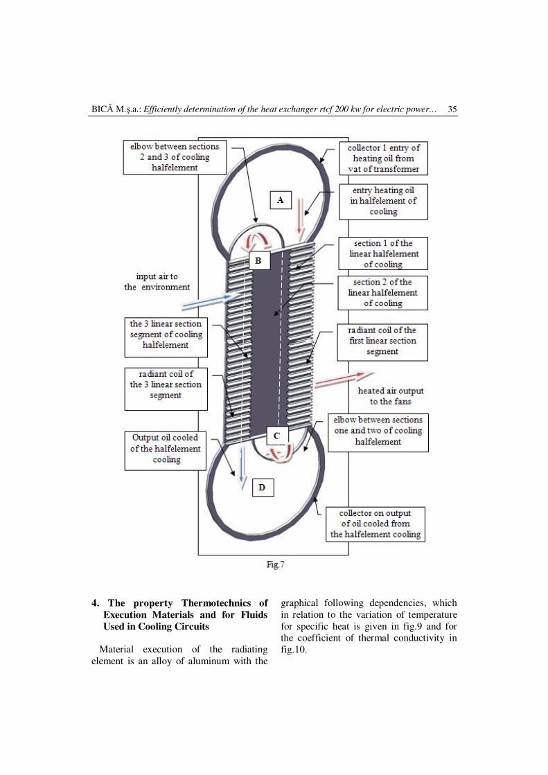
to study in the simulation with M.E.F. A whole section of halfelement cooling
which is survey analysis with M.E.F.
presenting elements attached proper
cooling system is shown in fig.7.
In this section were marked by means of fluid flow in the cooling system of the
hydraulic and pneumatic systems.
Fig.4 Fig.5 Fig.6
3. The Factors that Generate the Errors
of Calculation and Affect the
Quantitative and Qualitative the Heat
Exchange
As will be shown in comparison between
theoretical calculation and the experimental measurements, the errors occur in acceptable
limits are based on the following
justifications: - the important deformation of cooling
wings from assembly fig.4, which change
the flow aerodynamics and the heat exchange;
- the imperfect adjustment of the radiating
wing of halfelement contact cooling
which increase the contact surface due the stik;
- the partial closure of slit input in
hydraulic circuit of halfelement cover by
welding fig.8, which disrupt the hydraulic flow.
Fig. 8
BICĂ M.ş.a.: Efficiently determination of the heat exchanger rtcf 200 kw for electric power… 35
4. The property Thermotechnics of
Execution Materials and for Fluids
Used in Cooling Circuits
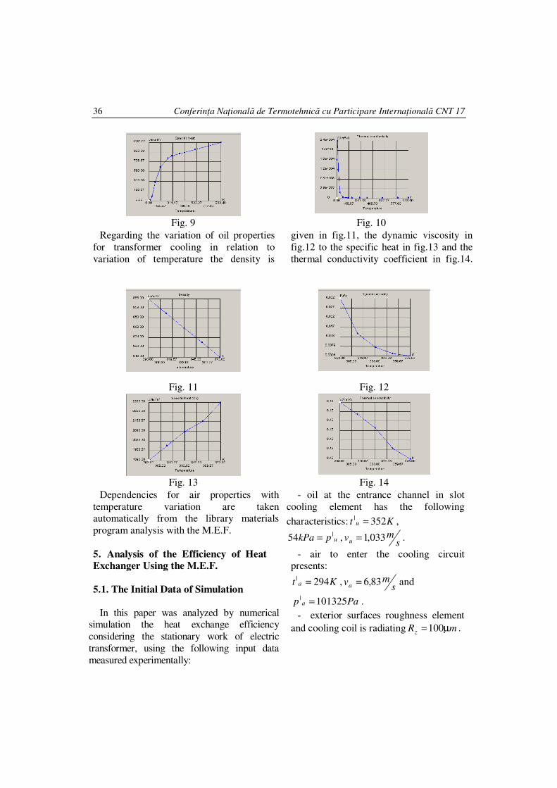
Material execution of the radiating
element is an alloy of aluminum with the
graphical following dependencies, which
in relation to the variation of temperature
for specific heat is given in fig.9 and for the coefficient of thermal conductivity in
fig.10.
Conferinţa Naţională de Termotehnică cu Participare Internaţională CNT 17
36
Fig. 9 Fig. 10
Regarding the variation of oil properties
for transformer cooling in relation to
variation of temperature the density is
given in fig.11, the dynamic viscosity in
fig.12 to the specific heat in fig.13 and the
thermal conductivity coefficient in fig.14.
Fig. 11 Fig. 12
Fig. 13 Fig. 14
Dependencies for air properties with
temperature variation are taken automatically from the library materials
program analysis with the M.E.F.
5. Analysis of the Efficiency of Heat
Exchanger Using the M.E.F.
5.1. The Initial Data of Simulation In this paper was analyzed by numerical
simulation the heat exchange efficiency
considering the stationary work of electric
transformer, using the following input data
measured experimentally:
- oil at the entrance channel in slot
cooling element has the following
characteristics: Kt u 352| = ,
upkPa |54 = ,s
mvu 033,1= .
- air to enter the cooling circuit presents:
Kt a 294| = ,s
mva 83,6= and
Pap a 101325| = .
- exterior surfaces roughness element
and cooling coil is radiating mRz µ=100 .
BICĂ M.ş.a.: Efficiently determination of the heat exchanger rtcf 200 kw for electric power…
37
With observation that the rate of flow of oil to average input channel slot cooling
element was determined as follows:
- the flow of the pump
is: smQu /0125,0 3= ;
- the section of slot of channel inside a
cooling element
is: 230 610,5028,0002,0 mS =×= ;
- the number of elements in the battery
cooling are: 36=n ;
- the number of batteries cooling: 6=N ;
- the average oil velocity at the entrance of
the channel slot cooling element
is:s
mnNSQv uu 033,1)/( 0 == .
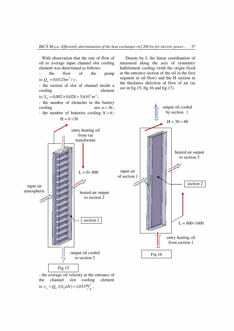
Denote by L the linear coordination of measured along the axis of symmetry
halfelement cooling (with the origin fixed
at the entrance section of the oil in the first segment in oil flow) and the H section in
the thickness direction of flow of air (as
see in fig.15, fig.16 and fig.17).
L = 800÷1600
H = 30 ÷ 60
input air
of section 1
heated air output
to section 3
entry heating oil
from section 1
output oil cooled
by section 3
Fig.16
section 2
H = 0 ÷30
L = 0÷ 800
heated air output to section 2
input air
atmospheric
entry heating oil
from vat transformer
output oil cooled
to section 2
Fig.15
section 1
Conferinţa Naţională de Termotehnică cu Participare Internaţională CNT 17
38
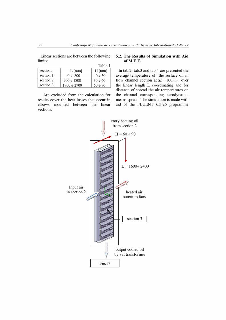
Linear sections are between the following limits:
Table 1 sections L [mm] H [mm]
section 1 0 ÷ 800 0 ÷ 30
section 2 900 ÷ 1800 30 ÷ 60
section 3 1900 ÷ 2700 60 ÷ 90
Are excluded from the calculation for
results cover the heat losses that occur in elbows mounted between the linear
sections.
5.2. The Results of Simulation with Aid
of M.E.F.
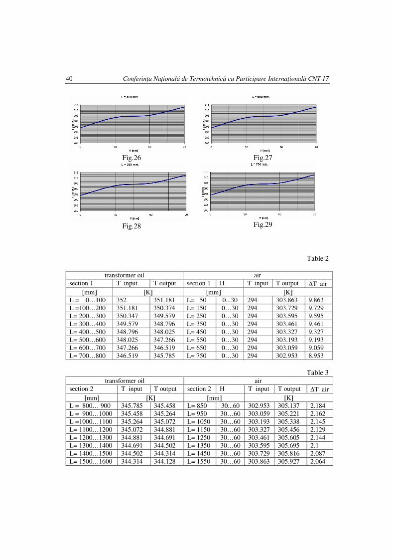
In tab.2, tab.3 and tab.4 are presented the
average temperature of the surface oil in
flow channel section at mmL 100=∆ over
the linear length L coordinating and for distance of spread the air temperatures on
the channel corresponding aerodynamic
means spread. The simulation is made with aid of the FLUENT 6.3.26 programme
output cooled oil
by vat transformer
L = 1600÷ 2400
H = 60 ÷ 90
Input air in section 2 heated air
output to fans
entry heating oil
from section 2
Fig.17
section 3
BICĂ M.ş.a.: Efficiently determination of the heat exchanger rtcf 200 kw for electric power…
39
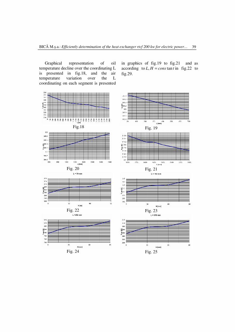
Graphical representation of oil
temperature decline over the coordinating L
is presented in fig.18, and the air temperature variation over the L
coordinating on each segment is presented
in graphics of fig.19 to fig.21 and as
according to tconsHL tan, = in fig.22 to
fig.29.
Fig.18
Fig. 19
Fig. 20
Fig. 21
Fig. 22
Fig. 23
Fig. 24
Fig. 25
Conferinţa Naţională de Termotehnică cu Participare Internaţională CNT 17
40
Fig.26
Fig.28
Fig.27
Fig.29
Table 2
transformer oil air
section 1 T input T output section 1 H T input T output ∆T air
[mm] [K] [mm] [K]
L = 0…100 352 351.181 L= 50 0...30 294 303.863 9.863
L =100…200 351.181 350.374 L= 150 0…30 294 303.729 9.729
L= 200…300 350.347 349.579 L= 250 0…30 294 303.595 9.595
L= 300…400 349.579 348.796 L= 350 0…30 294 303.461 9.461
L= 400…500 348.796 348.025 L= 450 0…30 294 303.327 9.327
L= 500…600 348.025 347.266 L= 550 0…30 294 303.193 9.193
L= 600…700 347.266 346.519 L= 650 0…30 294 303.059 9.059
L= 700…800 346.519 345.785 L= 750 0…30 294 302.953 8.953
Table 3 transformer oil air
section 2 T input T output section 2 H T input T output ∆T air
[mm] [K] [mm] [K]
L = 800… 900 345.785 345.458 L= 850 30...60 302.953 305.137 2.184
L = 900…1000 345.458 345.264 L= 950 30…60 303.059 305.221 2.162
L =1000…1100 345.264 345.072 L= 1050 30…60 303.193 305.338 2.145
L= 1100…1200 345.072 344.881 L= 1150 30…60 303.327 305.456 2.129
L= 1200…1300 344.881 344.691 L= 1250 30…60 303.461 305.605 2.144
L= 1300…1400 344.691 344.502 L= 1350 30…60 303.595 305.695 2.1
L= 1400…1500 344.502 344.314 L= 1450 30…60 303.729 305.816 2.087
L= 1500…1600 344.314 344.128 L= 1550 30…60 303.863 305.927 2.064
BICĂ M.ş.a.: Efficiently determination of the heat exchanger rtcf 200 kw for electric power…
41
Table 4
transformer oil air
section 3 T input T output T input section 3 T input T output ∆T air
[mm] [K] [mm] [K]
L =1600…1700 344.128 343.613 L= 1650 60...90 305.927 313.995 7.668
L =1700…1800 343.613 343.106 L= 1750 60…90 305.816 313.402 7.586
L =1800…1900 343.106 342.603 L= 1850 60…90 305.695 313.197 7.572
L= 1900…2000 342.603 342.481 L= 1950 60…90 305.605 313.160 7.555
L= 2000…2100 342.481 342.318 L= 2050 60…90 305.456 312.997 7.541
L= 2100…2200 342.318 341.972 L= 2150 60…90 305.338 312.876 7.538
L= 2200…2300 341.972 341.515 L= 2250 60…90 305.221 312.746 7.525
L= 2300…2400 341.515 341.029 L= 2350 60…90 305.137 312.627 7.490
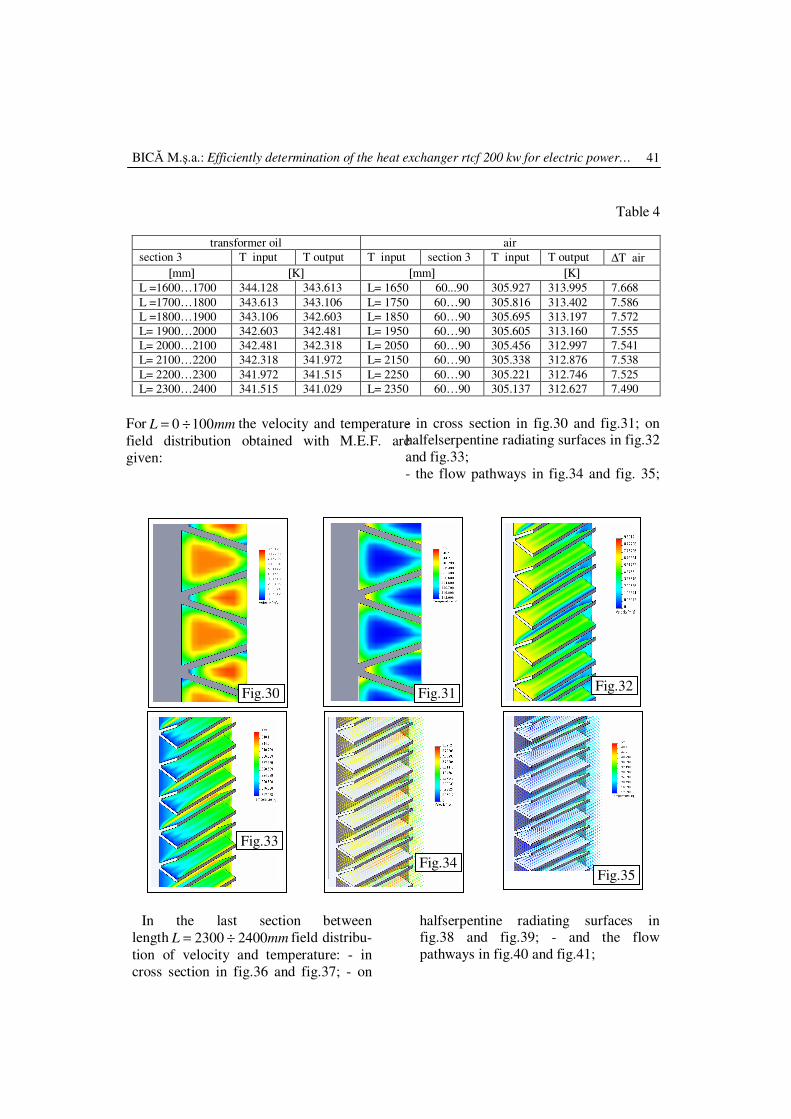
For mmL 1000 ÷= the velocity and temperature
field distribution obtained with M.E.F. are
given:
- in cross section in fig.30 and fig.31; on halfelserpentine radiating surfaces in fig.32
and fig.33;
- the flow pathways in fig.34 and fig. 35;
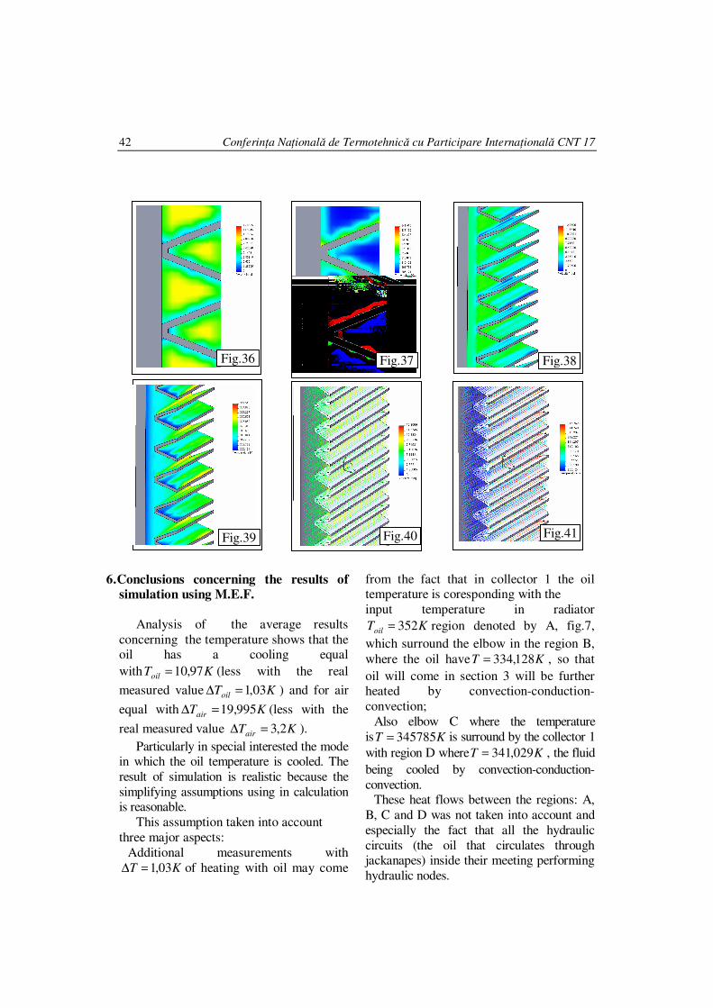
In the last section between
length mmL 24002300 ÷= field distribu-
tion of velocity and temperature: - in
cross section in fig.36 and fig.37; - on
halfserpentine radiating surfaces in fig.38 and fig.39; - and the flow
pathways in fig.40 and fig.41;
Fig.30 Fig.31
Fig.32
Fig.33
Fig.34 Fig.35
Conferinţa Naţională de Termotehnică cu Participare Internaţională CNT 17
42
6.Conclusions concerning the results of
simulation using M.E.F.
Analysis of the average results
concerning the temperature shows that the oil has a cooling equal
with KToil 97,10= (less with the real
measured value KToil 03,1=∆ ) and for air
equal with KTair 995,19=∆ (less with the
real measured value KTair 2,3=∆ ).
Particularly in special interested the mode in which the oil temperature is cooled. The
result of simulation is realistic because the
simplifying assumptions using in calculation is reasonable.
This assumption taken into account
three major aspects:
Additional measurements with
KT 03,1=∆ of heating with oil may come
from the fact that in collector 1 the oil temperature is coresponding with the
input temperature in radiator
KToil 352= region denoted by A, fig.7,
which surround the elbow in the region B,
where the oil have KT 128,334= , so that
oil will come in section 3 will be further heated by convection-conduction-
convection;
Also elbow C where the temperature
is KT 345785= is surround by the collector 1
with region D where KT 029,341= , the fluid
being cooled by convection-conduction-
convection. These heat flows between the regions: A,
B, C and D was not taken into account and
especially the fact that all the hydraulic
circuits (the oil that circulates through jackanapes) inside their meeting performing
hydraulic nodes.
Fig.36
Fig.37 Fig.38
Fig.39
Fig.40 Fig.41
BICĂ M.ş.a.: Efficiently determination of the heat exchanger rtcf 200 kw for electric power…
43
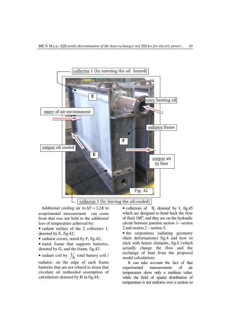
Additional cooling air to KT 2,3=∆ to
exeprimental measurement can come from that was not held to the additional
loss of temperature achieved by:
• radiant surface of the 2 collectors 1,
denoted by E, fig.42;
• radiator covers, noted by F, fig.42;
• metal frame that supports batteries,
denoted by G, and the frame, fig.43.
• radiant coil by 6
1 total battery coil /
radiator, on the edge of each frame
batteries that are not related to items that circulate oil (unheeded assumption of
calculation) denoted by H in fig.44;
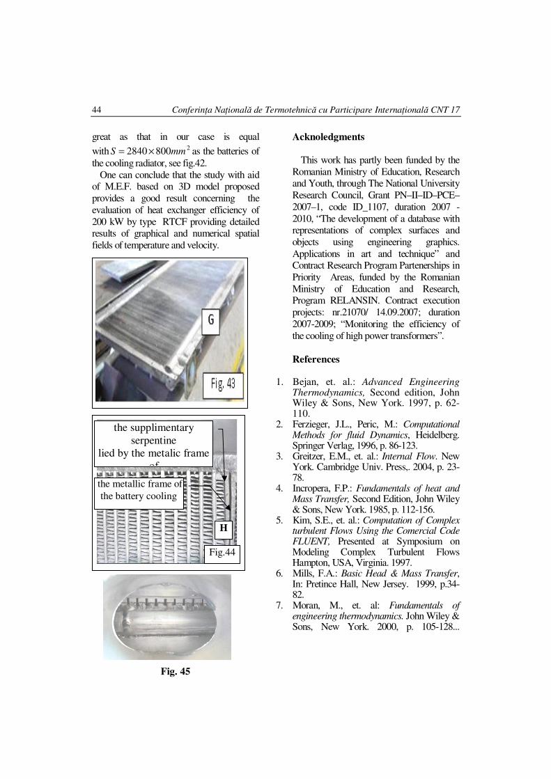
• collectors of II, denoted by I, fig.45
which are designed to bend back the flow
of fluid 1800, and they are on the hydraulic
circuit between junction section 1– section 2 and section 2 – section 3;
• the serpentines radiating geometry
(their deformations) fig.4 and how to
stick with heater elements, fig.6 (which
actually change the flow and the exchange of heat from the proposed
model calculation).
It can take account the fact of that experimental measurements of air
temperature show only a medium value,
while the field of spatial distribution of temperature is not uniform over a section so
Conferinţa Naţională de Termotehnică cu Participare Internaţională CNT 17
44
great as that in our case is equal
with 28002840 mmS ×= as the batteries of
the cooling radiator, see fig.42.
One can conclude that the study with aid of M.E.F. based on 3D model proposed
provides a good result concerning the
evaluation of heat exchanger efficiency of
200 kW by type RTCF providing detailed results of graphical and numerical spatial
fields of temperature and velocity.
Fig. 45
Acknoledgments
This work has partly been funded by the
Romanian Ministry of Education, Research and Youth, through The National University
Research Council, Grant PN–II–ID–PCE–
2007–1, code ID_1107, duration 2007 -
2010, “The development of a database with representations of complex surfaces and
objects using engineering graphics.
Applications in art and technique” and Contract Research Program Partenerships in
Priority Areas, funded by the Romanian
Ministry of Education and Research, Program RELANSIN. Contract execution
projects: nr.21070/ 14.09.2007; duration
2007-2009; “Monitoring the efficiency of
the cooling of high power transformers”.
References
1. Bejan, et. al.: Advanced Engineering Thermodynamics, Second edition, John Wiley & Sons, New York. 1997, p. 62-110.
2. Ferzieger, J.L., Peric, M.: Computational Methods for fluid Dynamics, Heidelberg. Springer Verlag, 1996, p. 86-123.
3. Greitzer, E.M., et. al.: Internal Flow. New York. Cambridge Univ. Press,. 2004, p. 23-78.
4. Incropera, F.P.: Fundamentals of heat and Mass Transfer, Second Edition, John Wiley & Sons, New York. 1985, p. 112-156.
5. Kim, S.E., et. al.: Computation of Complex turbulent Flows Using the Comercial Code FLUENT, Presented at Symposium on Modeling Complex Turbulent Flows Hampton, USA, Virginia. 1997.
6. Mills, F.A.: Basic Head & Mass Transfer, In: Pretince Hall, New Jersey. 1999, p.34-82.
7. Moran, M., et. al: Fundamentals of engineering thermodynamics. John Wiley & Sons, New York. 2000, p. 105-128...
the metallic frame of
the battery cooling
the supplimentary
serpentine
lied by the metalic frame
of
H
Fig.44