effects of thermally induced birefringence in high-output-power electro-optically q-switched nd:yag...
TRANSCRIPT
Effects of thermally induced birefringence inhigh-output-power electro-optically Q-switchedNd:YAG lasers and their compensation
S. Z. Kurtev, 0. E. Denchev, and S. D. Savov
We show that thermally induced birefringence in an electro-optical crystal can play an important role inQ-switched Nd:YAG lasers with a high average power output. A compensation of the thermal effects inboth active-element and electro-optical crystals is achieved by employing two identical Pockels cellsinstead of one, with a Tr/2 polarization rotator between them in the so-called ring modulator.Experiments that are carried out show that undesirable thermopolarization effects are essentiallyeliminated by using this new optical configuration. A detailed description in terms of Jones matrices ofthe properties of the proposed resonator is also included.
1. IntroductionHighly energized giant-pulse laser beams with a highaverage power output have a wide range of applica-tions in laser technology, lidars, scientific research,etc. The most commonly used sources of this kind ofradiation are electro-optically Q-switched Nd:YAGlasers. Electro-optical (E-O) Q switching assumes awell-defined state of polarization of the radiationinside the laser cavity, which is usually achieved byplacing a polarizer in the said cavity. The thermallyinduced birefringence in some components of thelaser cavity that accompanies the laser operation athigh power levels could then infringe on the predeter-mined polarization, thus leading to undesirable sideeffects. Such effects have generally been observed inthe active medium. They are due to the heating ofthe active element (AE) during the pumping cycle andare proportional to the pumping power. These ef-fects have already been studied in detailI and severaltypes of resonator with different optical schemes havebeen proposed to compensate for the depolarization ofthe radiation by the active medium.1-3 These resona-tors allow for a considerable increase of the averagepower level while still generating giant pulses of highquality.
A further increase of optical power in the cavitycould easily lead to a thermally induced birefringence
The authors are with the Institute of Laser Technique, SofiaUniversity, 33A Galichitsa Street, 1126 Sofia, Bulgaria.
Received 10 September 1990.0003-6935/93/030278-08$05.00/0.3 1993 Optical Society of America.
in other cavity components because of their heatingas a result of the weak light absorption. In thisaspect the E-O crystals are the most critical compo-nents, since it is difficult to combine both good E-Oproperties and an absolute transparency at the lasergeneration wavelength. Richards,2 for instance,while experimenting with a resonator that was able tocompensate for the depolarization in the active me-dium, observed a reduction in the energy of thegenerated giant pulses at a 15-W average poweroutput level. He explains this reduction in the pulseenergy by the depolarization in the LiNbO3 E-Ocrystal used in the experiment. The thermally in-duced depolarization due to weak light absorption inKDP and KD*P has also been investigated by Khris-tov et al.4 In their opinion the depolarization effectscould quell the E-O Q-switching of light modulatorsbased on these crystals. They find these effects in aKD*P-based light modulator at powers of 15 W to beconsiderable.
The influence of thermally induced depolarizationin the E-O crystal on the quality of the generatedgiant pulses may be explained by considering theconventional cavity of an E-O Q-switched laser [shownin Fig. 1(a)]. At a high average power of generation,and by assuming relatively high repetition rates, weestablish a steady-state temperature field throughoutthe E-O crystal. The depolarization exists in bothstates of the resonator: open (no voltage applied tothe E-O crystal) and closed (high voltage is applied).When the resonator is open the depolarized part ofthe radiation leaves the cavity at the polarizer as aloss. In the closed state the depolarized part of the
278 APPLIED OPTICS / Vol. 32, No. 3 / 20 January 1993

/ I
C2 P 2 Ml
(a)
200.
100.
El0t[mJ1
100-
50
2 4 6 8 10
I E2o'3tmJ]
o
.20
12 Pout (WI
(b)Fig. 1. Experiments with a conventional E-O Q-switched Nd:YAGlaser: (a) optical scheme; Ml, M2, mirrors; PC, Pockels cell; P,polarizer; Y, active element; 1, laser output; 2, 3, depolarizedcomponent outputs for the active medium and E-O crystal, respec-tively; (b) results; 1, total energy per pulse Eoutl from output 1; 2,depolarized pulse energy Eout2 due to the active medium; 3,depolarized pulse energy Eout3 due to the E-0 crystal; 4, relativeQ-switched pulse energy EQr1 measured by a photodiode as afunction of average output power Pout.
radiation passes through the polarizer, thus giving alaser generation feedback. Thus we see that it ispossible for a free-running generation to appear at acertain level of amplification. This leads to a reduc-tion of the inverse population, and, thus, to a reduc-tion of the energy of the Q-switched pulses.
Following Koechnerl we calculated that, in orderto achieve a giant-pulse energy of 250 mJ from a4(6.3 x 75 mm Nd:YAG rod, the small-signal single-pass gain of the active medium must be Go -exp(gol) 45, where go is the small-signal gaincoefficient and I is the length of the rod. In this casethe optimal output coupling R is approximately 0.20.The threshold balance shows that under these condi-tions a depolarization of 2% in the Pockels cell (PC)leads to a 27% reduction of the initial inverse popula-tion no:
go' no'
go no
-ln(R) - ln(0.02) 0.732 ln(Go) 0.3
where go' and no' are the reduced values that are dueto the undesirable generation in the closed cavity.At a certain level of depolarization the Q switchingmight fail completely.
Here we present for what is, to our knowledge, thefirst time, a resonator that is able to compensatesimultaneously for the thermal depolarization in
both the active medium and the modulator. Usingthis type of resonator, we are able to obtain a furtherincrease of the average output power range in whichQ-switched pulses of high quality are still generated.
2. Conventional Cavity ExperimentsIn order to observe the expected thermally inducedpolarization effects in E-O Q-switched Nd:YAG la-sers, we carried out some experiments with a conven-tional linear laser resonator, shown in Fig. 1(a). Weneed these results in order to compare them withthose obtained with the new optical configurationthat compensates for the depolarization effects. Inthe experiment we used a PC based on the longitudi-nal E-O effect in a crystal of KD*P, ¢10 mm x 25mm. In order to show the expected effects moreclearly within the range of the available averagepower output, we chose a KD*P crystal with anoptical density of aL 0.03 (a is the absorptioncoefficient and L is the length of the KD*P crystal), avalue that is relatively higher than the standard-quality KD*P crystal's optical density. For the samereason we chose an output mirror Ml with a reflectiv-ity R = 0.45, which is higher than the optimum one.Both mirror Ml and the rear mirror M2 were flat.The AE was Nd:YAG, +6.3 mm x 76 mm, grown withits cylindrical axes along the [111] direction and withantireflective coated ends. A multilayer dielectric-coated mirror was used as polarizer P. It enabled usto measure the depolarized components of the intra-cavity radiation, both those due to the active elementas well as those due to the E-O crystal, arising indirections 2 and 3, respectively [see Fig. 1(a)]. Thelasing was in direction 1. The light power in thesethree directions was measured with a power meterScientech 365. The laser repetition rate was vari-able from 10 to 110 pulses/s. The pumping pulseshad a fixed duration of 0.35 ms and a variable energyof up to 40 J/pulse. No intracavity diaphragm wasused, so the laser beam had a multimode transversestructure and a diameter of 6.3 mm. The temporalform of the Q-switched pulses was monitored by aphotodiode and an oscilloscope. The experimentalresults obtained in this experiment are shown in Fig.1(b). The values shown represent output pulse ener-gies versus the average power Putl from output 1,which are changed by varying the repetition rate ofthe pulses. The superscripts denote the output num-ber (for the three different directions). Curves 2 and3 are related to the ordinate axis on the right-handside of the figure. Curve 1 depicts the decrease inthe energy output that is due to radiation lossescaused by the total birefringence in the cavity.Curves 2 and 3 represent the losses that are due tobirefringence in the AE and in the E-O crystal,respectively. The losses caused by the induced bire-fringence in the AE (curve 2) were seen to increasecontinuously with the increase of Pot, and a satura-tion was observed at a value of 30% of Potl. Thetypical crosslike tranversal intensity distributioncaused by depolarization in the cavity was observed athigh-power-output levels.
20 January 1993 / Vol. 32, No. 3 / APPLIED OPTICS 279
l -
Under these experimental conditions the depolariza-tion in the E-O crystal began to take place at a poweroutput of 5 W, as can be seen from curve 3 in Fig. 1(b).We suggest that the weak emission detected fromoutputs 2 and 3 at values of power Pout < 5 W wascaused by the imperfection of the polarizer. With afurther increase in Pout', the depolarized radiationcomponent increased considerably and at approxi-mately 10 W it reached 15% of the value of the pulseenergy obtained from the cold cavity.
Changes in the oscillogram of the laser outputpulse were also noticed. At powers of approximately6.5 W [in Fig. 1(b) this value is denoted by a verticaldashed line] peaks of free generation appear beforethe Q pulse. Moving toward greater Pout, accordingto predictions, the relative part of the free-runninggeneration increases; therefore the energy of the Qpulse is less than that determined from the outputpower. The relative energy EQr of the Q-switchedpulses was measured by a photodiode and integratingcircuit (T 1 ps). The dependence EQr on Pout isshown by curve 4, where the scale is in percentages ofthe value obtained from the cold cavity.
The experiment showed that this effect could not beovercome by varying the high voltage applied to theE-O crystal. This means that the spatially inhomo-geneous anisotropy was responsible for the above-mentioned effects.
Thermal lensing in the cavity, which leads to achange of beam divergence in the E-O crystal, alsoneeds to be checked as being responsible for energyoutput restrictions. Taking into account the mea-sured output beam divergence and the location of theE-O crystal in the cavity, we calculated that the lossescaused by thermal lensing were negligible. This factwas verified with an additional experiment, in whichthe divergence was controlled by an intracavity tele-scope placed between the output mirror Ml and theAE. The ratio Pout3/Poutl was found to be constantfor all ranges of the cavity stability.
So here we provided an experimental confirmationthat the thermally induced spatially inhomogeneousanisotropy in the E-O crystal is also important inregard to the quality of the Q-switched pulses.
3. Thermal Birefringence in a KD*P Q-SwitchThis section is designed to clarify the nature ofthermo-optical phenomena that appear in E-O crys-tals. We take advantage of the principal resultsobtained by Khristov et al.,4 representing them in aconvenient form for further use (see Appendix A).Our consideration is restricted to the KD*P crystalsbecause we used this type of crystal in our experments.The crystal is cylindrically cut parallel to its opticalaxis z. A laser beam of radius r, which is muchsmaller than the crystal's radius, propagates alongthe z axis. The beam is assumed to have a uniformtransversal intensity distribution. We also assumethat the light absorption in the crystal is weak(aL << 1). Under these conditions a temperaturefield with a parabolic cross-sectional distribution
establishes, inside the crystal,4 that
T(r) = To + Po (r02 - r), (1)
where r, cm, is the distance from the center of thelaser beam; r is the beam radius; Po, W cm- 3 , is thetotal dissipated power per unit volume; and K, Wcm-' deg-', is the thermal conductivity coefficient.To depends on the boundary conditions.
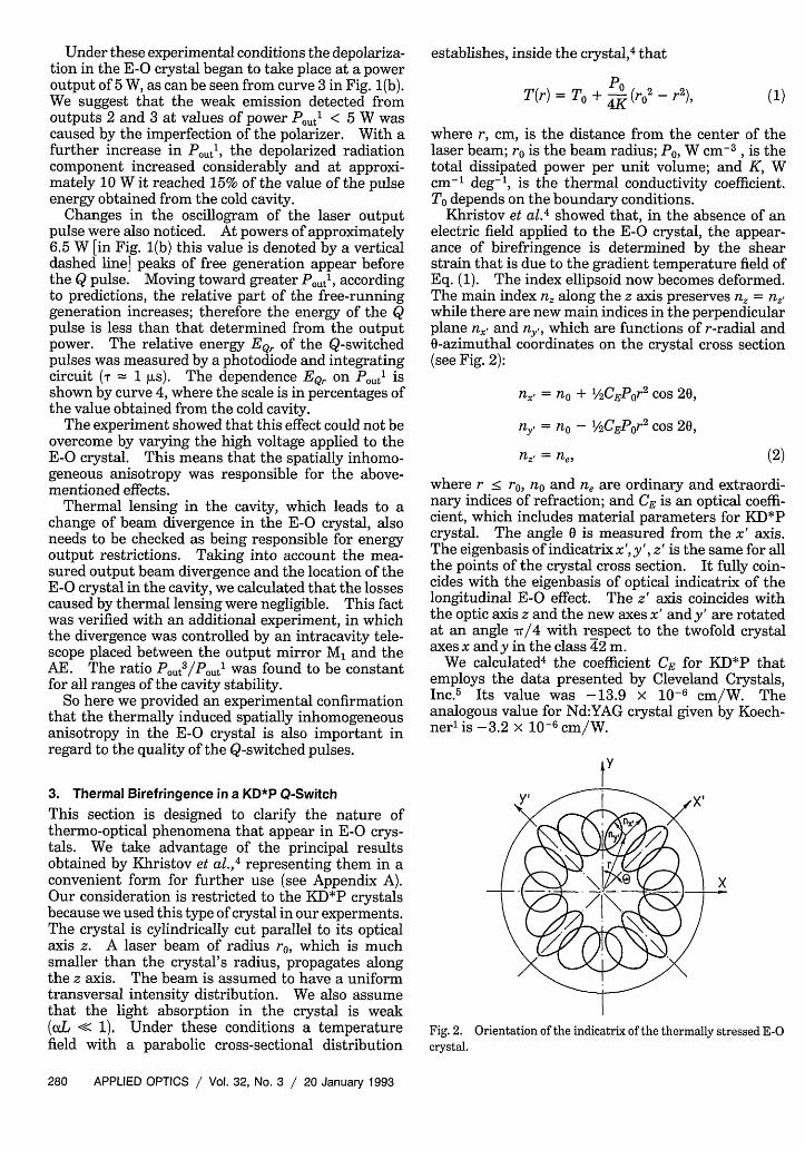
Khristov et al.4 showed that, in the absence of anelectric field applied to the E-O crystal, the appear-ance of birefringence is determined by the shearstrain that is due to the gradient temperature field ofEq. (1). The index ellipsoid now becomes deformed.The main index n, along the z axis preserves n, = n,while there are new main indices in the perpendicularplane n, and ny, which are functions of r-radial and0-azimuthal coordinates on the crystal cross section(see Fig. 2):
n, = no + 112CEPor 2 cos 20,
ny = no- 1/2CEPor2 cos 20,
nz = nei (2)
where r < r, no and n, are ordinary and extraordi-nary indices of refraction; and CE is an optical coeffi-cient, which includes material parameters for KD*Pcrystal. The angle 0 is measured from the x' axis.The eigenbasis of indicatrix x', y', z' is the same for allthe points of the crystal cross section. It fully coin-cides with the eigenbasis of optical indicatrix of thelongitudinal E-O effect. The z' axis coincides withthe optic axis z and the new axes x' and y' are rotatedat an angle Tr/4 with respect to the twofold crystalaxes x and y in the class 42 m.
We calculated 4 the coefficient CE for KD*P thatemploys the data presented by Cleveland Crystals,Inc.5 Its value was -13.9 x 10⁻⁶ cm/W. Theanalogous value for Nd:YAG crystal given by Koech-nerl is -3.2 x 10⁻⁶ cm/W.
Fig. 2. Orientation of the indicatrix of the thermally stressed E-Ocrystal.
280 APPLIED OPTICS / Vol. 32, No. 3 / 20 January 1993
by
Passing through the heated E-O crystal, the compo-nents of a given polarization (along x' and y' axes)obtain phase difference Ai\,, depending on r and 0:
2rrA(,= -LCEPor 2 cos 20, (3)
where L is the crystal length.If a voltage U is applied to the E-O crystal along its
optical axis z and there is a temperature gradient inthe crystal, another effect should be taken into ac-count: the E-O effect depends on the temperaturethrough ano/aT and r63/aT, where r63 is the E-Ocoefficient. At the temperature field of Eq. (1), thisresults in an additional spatially inhomogeneous phaseshift4 :
3 ano l ar6 3 1 P )/\ = ar63n03U 3 T n + T r63 2K(ro -r
2 ) (4)
Assuming quarter-wave voltage and a crystal lengthL = 2.5 cm, we can evaluate the relative contributionof the second effect in the phase shift from Eqs. (3)and (4):
A + <r 0.12. (5)
This contribution in terms of intensity is less than6%. It is obvious that the thermoelastic effect is thedominant effect.
It is clear from the above expressions that straight-forward ways of reducing the thermal effects in theE-O crystal are to choose a crystal with minimalabsorption, shorten the crystal length as much aspossible, and place the crystal in the cavity so that thelight field is minimal. The analysis points out, how-ever, that the most effective way to expand signifi-cantly the power range of an E-O Q-switched laser isby using optical schemes for compensating the depo-larization induced in the E-O crystal by the ther-moelastic effect.
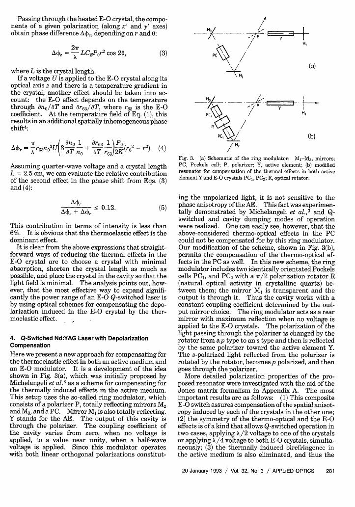
4. Q-Switched Nd:YAG Laser with DepolarizationCompensationHere we present a new approach for compensating forthe thermoelastic effect in both an active medium andan E-O modulator. It is a development of the ideashown in Fig. 3(a), which was initially proposed byMichelangeli et al.3 as a scheme for compensating forthe thermally induced effects in the active medium.This setup uses the so-called ring modulator, whichconsists of a polarizer P, totally reflecting mirrors M2and M3, and a PC. Mirror M1 is also totally reflecting.Y stands for the AE. The output of this cavity isthrough the polarizer. The coupling coefficient ofthe cavity varies from zero, when no voltage isapplied, to a value near unity, when a half-wavevoltage is applied. Since this modulator operateswith both linear orthogonal polarizations constitut-
Mot
PC~H
H2
PC54 M,
M2
Fig. 3. (a) Schematic of the ring modulator: M-M3, mirrors;PC, Pockels cell; P, polarizer; Y, active element; (b) modifiedresonator for compensation of the thermal effects in both activeelement Y and E-O crystals PC1, PC2 ; R, optical rotator.
ing the unpolarized light, it is not sensitive to thephase anisotropy of the AE. This fact was experimen-tally demonstrated by Michelangeli et al.,3 and Q-switched and cavity dumping modes of operationwere realized. One can easily see, however, that theabove-considered thermo-optical effects in the PCcould not be compensated for by this ring modulator.Our modification of the scheme, shown in Fig. 3(b),permits the compensation of the thermo-optical ef-fects in the PC as well. In this new scheme, the ringmodulator includes two identically orientated Pockelscells PC1 , and PC2 with a rr/2 polarization rotator R(natural optical activity in crystalline quartz) be-tween them; the mirror M1 is transparent and theoutput is through it. Thus the cavity works with aconstant coupling coefficient determined by the out-put mirror choice. The ring modulator acts as a rearmirror with maximum reflection when no voltage isapplied to the E-O crystals. The polarization of thelight passing through the polarizer is changed by therotator from ap type to an s type and then is reflectedby the same polarizer toward the active element Y.The s-polarized light reflected from the polarizer isrotated by the rotator, becomes p polarized, and thengoes through the polarizer.
More detailed polarization properties of the pro-posed resonator were investigated with the aid of theJones matrix formalism in Appendix A. The mostimportant results are as follows: (1) This compositeE-O switch assures compensation of the spatial anisot-ropy induced by each of the crystals in the other one;(2) the symmetry of the thermo-optical and the E-Oeffects is of a kind that allows Q-switched operation intwo cases, applying X/2 voltage to one of the crystalsor applying A/4 voltage to both E-O crystals, simulta-neously; (3) the thermally induced birefringence inthe active medium is also eliminated, and thus the
20 January 1993 / Vol. 32, No. 3 / APPLIED OPTICS 281
whole cavity becomes insensitive to thermopolariza-tion effects, independently of their origin.
5. Experimental
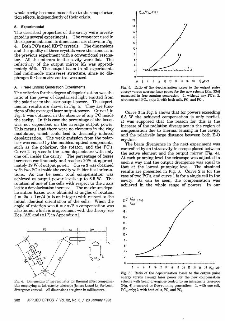
The described properties of the cavity were investi-gated in several experiments. The resonator used inthe experiments and its dimensions are shown in Fig.4. Both PC's used KD*P crystals. The dimensionsand the quality of these crystals were the same as inthe previous experiment with a conventional resona-tor. All the mirrors in the cavity were flat. Thereflectivity of the output mirror Ml was approxi-mately 45%. The output beam in all experimentshad multimode transverse structure, since no dia-phragm for beam size control was used.
202
18
16 -
14 -
12
10-
8-
6-
4.
0, 2 1 6 8 1 ? I1. 2
0 2 4 6 8 12 12 14 16 18 20 P"'t IW I
A. Free-Running Generation ExperimentsThe criterion for the degree of depolarization was theratio of the power of depolarized light emitted fromthe polarizer to the laser output power. The experi-mental results are shown in Fig. 5. They are func-tions of the averaged laser output power. Curve 1 inFig. 5 was obtained in the absence of any PC insidethe cavity. In this case the percentage of the losseswas not dependent on the average output power.This means that there were no elements in the ringmodulator, which could lead to thermally induceddepolarization. The weak emission from the polar-izer was caused by the nonideal optical components,such as the polarizer, the rotator, and the PC's.Curve 2 represents the same dependence with onlyone cell inside the cavity. The percentage of lossesincreases continuously and reaches 20% at approxi-mately 19 W of output power. Curve 3 was obtainedwith two PC's inside the cavity with identical orienta-tions. As can be seen, total compensation wasachieved at output power levels up to 6.5 W. Therotation of one of the cells with respect to the z axisled to a depolarization increase. The maximum depo-larization losses were obtained at angles of rotationo = (2n + 1)7r/4 (n is an integer) with respect to theinitial identical orientation of the cells. When theangle of rotation was 0 = nr/2 a compensation wasalso found, which is in agreement with the theory [seeEqs. (A8) and (A17) in Appendix A].
M,
La
Fig. 4. Dimensions of the resonator for thermal effect compensa-tion employing an intracavity telescope (lenses Liand L2) for beamdivergence control. All dimensions are given in millimeters.
Fig. 5. Ratio of the depolarization losses to the output pulseenergy versus average laser power for the new scheme [Fig. 3(b)]measured in free-running generation: 1, without any PC's; 2,with one cell, PC,, only; 3, with both cells, PC, and PC2.
Curve 3 in Fig. 5 shows that for powers exceeding6.5 W the achieved compensation is only partial.It was supposed that the reason for this is theincrease of the radiation divergence in the region ofcompensation due to thermal lensing in the cavity,and the relatively large distance between both E-Ocrystals.
The beam divergence in the next experiment wascontrolled by an intracavity telescope placed betweenthe active element and the output mirror (Fig. 4).At each pumping level the telescope was adjusted insuch a way that the output divergence was equal tothat at the lowest pumping level. The obtainedresults are presented in Fig. 6. Curve 2 is for thecase of two PC's, and curve 1 is for a single cell in thecavity. As can be seen, the compensation wasachieved in the whole range of powers. In our
222- Eout(%
20 /
18
16
12 0
10 /
8-
6 0
2
0
2 4 6 8 10 12 11 16 18 20 22 24 26 28 Pot(W1l
Fig. 6. Ratio of the depolarization losses to the output pulseenergy versus average laser power for the new compensationscheme with beam divergence control by an intracavity telescope(Fig. 4) measured in free-running generation: 1, with one cell,PC,, only; 2, with both cells, PC1 and PC2.
282 APPLIED OPTICS / Vol. 32, No. 3 / 20 January 1993
EOU/ Elut /.
I
I�__ -_�_ _-_ t___�__Z
200-
150 -
100-
50 -
Eoutt[mJI
M 00 . . .
Eout [%j
*10
8
-6
.4
.2
0 2 4 6 8 10 12 14 16 18 20 22 P0ot [Wl
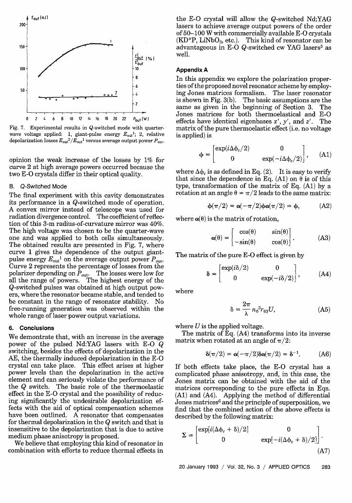
Fig. 7. Experimental results in Q-switched mode with quarter-wave voltage applied: 1, giant-pulse energy Etl; 2, relativedepolarization losses Eout2/E0 t' versus average output power Pout.
opinion the weak increase of the losses by 1% forcurve 2 at high average powers occurred because thetwo E-O crystals differ in their optical quality.
B. Q-Switched Mode
The final experiment with this cavity demonstratesits performance in a Q-switched mode of operation.A convex mirror instead of telescope was used forradiation divergence control. The coefficient of reflec-tion of this 3-m radius-of-curvature mirror was 40%.The high voltage was chosen to be the quarter-waveone and was applied to both cells simultaneously.The obtained results are presented in Fig. 7, wherecurve 1 gives the dependence of the output giant-pulse energy Eout on the average output power Pout.Curve 2 represents the percentage of losses from thepolarizer depending on Pout. The losses were low forall the range of powers. The highest energy of theQ-switched pulses was obtained at high output pow-ers, where the resonator became stable, and tended tobe constant in the range of resonator stability. Nofree-running generation was observed within thewhole range of laser power output variations.
6. Conclusions
We demontrate that, with an increase in the averagepower of the pulsed Nd:YAG lasers with E-O Qswitching, besides the effects of depolarization in theAE, the thermally induced depolarization in the E-Ocrystal can take place. This effect arises at higherpower levels than the depolarization in the activeelement and can seriously violate the performance ofthe Q switch. The basic role of the thermoelasticeffect in the E-O crystal and the possibility of reduc-ing significantly the undesirable depolarization ef-fects with the aid of optical compensation schemeshave been outlined. A resonator that compensatesfor thermal depolarization in the Q switch and that isinsensitive to the depolarization that is due to activemedium phase anisotropy is proposed.
We believe that employing this kind of resonator incombination with efforts to reduce thermal effects in
the E-O crystal will allow the Q-switched Nd:YAGlasers to achieve average output powers of the orderof 50-100 W with commercially available E-O crystals(KD*P, LiNbO3, etc.). This kind of resonator can beadvantageous in E-O Q-switched cw YAG lasers3 aswell.
Appendix AIn this appendix we explore the polarization proper-ties of the proposed novel resonator scheme by employ-ing Jones matrices formalism. The laser resonatoris shown in Fig. 3(b). The basic assumptions are thesame as given in the beginning of Section 3. TheJones matrices for both thermoelastical and E-Oeffects have identical eigenbases x', y', and z'. Thematrix of the pure thermoelastic effect (i.e. no voltageis applied) is
[exp(iA/+c/2)(Al)
where A4', is as defined in Eq. (2). It is easy to verifythat since the dependence in Eq. (Al) on 0 is of thistype, transformation of the matrix of Eq. (Al) by arotation at an angle 0 = vr/2 leads to the same matrix:
J(r/2) = i(-1/2)xc(Tr/2) = ,
where a(0) is the matrix of rotation,
[ cos()
- sin(0)sin(0) 1cos(0)]J
(A2)
(A3)
The matrix of the pure E-O effect is given by
exp(ii/2)(A4)
0 2 1
exp(-ib/2)] I
where
2= nI=xn36U (A)
where U is the applied voltage.The matrix of Eq. (A4) transforms into its inverse
matrix when rotated at an angle of rr/2:
8(r/2) = a(-,rr/2)8(Tr/2) = b-'. (A6)
If both effects take place, the E-O crystal has acomplicated phase anisotropy, and, in this case, theJones matrix can be obtained with the aid of thematrices corresponding to the pure effects in Eqs.(Al) and (A4). Applying the method of differentialJones matrices6 and the principle of superposition, wefind that the combined action of the above effects isdescribed by the following matrix:
= [exp[i(AiX, + )/2] 01
exp[-i(A4. + )/2]
(A7)
20 January 1993 / Vol. 32, No. 3 / APPLIED OPTICS 283
I
0
exp(-i&�,,/2) )
We assume a right-hand coordinate system todescribe the optical scheme. The z axis coincideswith the direction of light propagation, the x axis liesin the plane of the ring modulator, and the y-axisis perpendicular to this plane. The Jones vectorhas components [s] on the polarizer plane of in-cidence, where the subscripts s andp stand for s andppolarizations of the light, respectively. The orienta-tions of PC, and PC2 are identical and correspond tothe Q-switching operation, i.e., their optical axes z'coincide with the light propagation direction and theangle between the biaxial plane of the crystal and thex axis of the coordinate system equals r/4. If novoltage is applied, we make the ray traces in the cavityseparate for the s and the p polarizations. For the spolarization we have the following Jones matrix JS:
JS = PTMa( -1/4)4 R(- ±/2)<a( r/4)MPR, (A8)
and for thep polarization we have
JP = PRMOa(-ir/4)R(-v/2)oa(srr/4)MPT (A9)
Since the mirrors M2 and M3 are multilayer dielec-tric coated and since the incident rays are inclinedwith respect to the mirror planes, the p componentexperiences a given phase shift. When the effectivethicknesses of dielectric layers are X/4, the phaseshift equals 7r,7 and therefore the proper Jones matrixof the mirrors M is
I 0
=0 -1i. (A10)
The above conclusions are also correct for the polar-izer matrix of reflection:
F0 0PR=L 2R. (All)
where R is the amplitude coefficient of reflection fors-polarized light. The polarizer matrix of transpar-ency is:
matrices from the eigenbasis into the basis acceptedfor optical system description. The sign of the rota-tion angle is also taken into account with respect tothe number of reflections.
It is easy to verify that the matrix multiplication+R(±ir/2)+ equals R(±T7/2). In this case, the spa-tially inhomogeneous functions X, which are depen-dent on the absorbed power, vanish. This meansthat the phase anisotropy that is due to the ther-moelastic effect is compensated for in this type of ringmodulator. Thus the optical system description be-comes equivalent to that situation in which no PC'sare inside the ring modulator. Finally,
(L 11 0 ° ) 1 J=Js +Jp = TR[ M [ ]) TR[ ](A14)
The ring modulator coefficient of reflection with novoltage applied in terms of intensity is (TR)2. For apolarizer of good quality this coefficient is close to 1.By exploring the combined action of the thermoelasti-cal and the E-O effects, it is possible to consider twodifferent cases: high voltage is applied either (a) toone of the PC's or (b) to both the cells simultaneously.In the first case, the matrix of the PC to which thevoltage is applied is that of Eq. (A7); therefore thematrix multiplications that appear in Eqs. (A8) and(A9) are
0XR(±+[/2)( 0 = 0exp(-i8/2)
(PR(-+T/2) = -+Pexp(ib/2)
±exp(i8/2)1
-exp(-i8/2)1
O (A15)
The above multiplications are functions of the appliedvoltage only, and considering the proper signs in Eqs.(A8) and (A9) we can find the Jones matrix of the ringmodulator Ju with a voltage applied:
Ju = -cos -J.PT =[ ] (A12)
where T is the amplitude coefficient of transparencyfor p-polarized light. We consider that the rotator Rhas natural optical activity. Its Jones matrix is
R(±m/2) = _111
0 (A13)
This matrix changes its sign when changing theright-hand coordinate system into a left-hand one,which takes place at every reflection by mirror. Thisfact is taken into account in expressions (A8) and(A9). The upper sign corresponds to a counterclock-wise rotator, and the lower corresponds to a clockwiseone. The coordinate rotation matrices a are in theform of Eq. (A4). These matrices transform the P
Consequently, the coefficient of reflection of the ringmodulator is modulated by the function (1 + cos )/2.So the ring modulator reflectivity becomes
R(U) = (TR)2 (l + cos )/2.
In the second case it is necessary that certainrelations be satisfied, namely: If Eq. (A7) is thematrix 11 of PC,, then the matrix of the PC2 - 2must be
= [exp[i(A(c- - )/21s2=L °~
e x p [ -i ( A 40 -
exp[-i(A-~ - )/2]
(A17)
or vice versa. This relation can be obtained by (a)
284 APPLIED OPTICS / Vol. 32, No. 3 / 20 January 1993
(A16)
rotating one of the cells at an angle = r/2 withrespect to the initial, which is identical for bothcells' adjustment, according to Eqs. (A2) and (A6);or (b) by applying opposite electric fields to thecells [see Eq. (A5)]. In this case the following prod-ucts appear in Eqs. (A8) and (A9):
[ 0 ±exp(i8)]
Liexp(-i8) 0 J0 + exp(- i8)
L~:exp(i8) °
They are dependent on the applied voltages only.Now the Jones matrix of the ring modulator is
J = cos(8)J, (A19)
and for the reflection coefficient we obtain
R(U) = (TR)2 (1 + cos 28)/2.
The second case is more favorable with respect to
high-voltage commutation because, according to Eq.(A5), the operating voltage is two times lower than inthe first case. The cavity is closed when the appliedhigh voltage equals the quarter-wave one ( = r/2).
References1. W. Koechner, Solid-State Laser Engineering (Springer-Verlag,
New York, 1988), Chaps. 7 and 8.2. J. Richards, "Birefringence compensation in polarization cou-
pled lasers," Appl. Opt. 26, 2514-2517 (1987).3. G. Michelangeli, E. Penco, G, Giuliani, and E. Palange, "Q
switching and cavity dumping of high-power Nd:YAG laser bymeans of a novel electro-optic configuration," Opt. Lett. 11,360-362 (1986).
4. I. P. Khristov, I. V. Tomov, and S. M. Saltiel, "Self-heatingeffects in electro-optic light modulators," Opt. Quantum Elec-tron. 15, 289-295 (1983).
5. "Electro-optic properties of KH2PO4 and isomorphs," informa-tion sheet (Cleveland Crystals, Inc., Cleveland, Ohio, 1984).
6. R. C. Jones, "A new calculus for the treatment of optical sys-tems VII: properties of the N-matrices," J. Opt. Soc. Am. 38,671-685 (1948).
7. M. Born and E. Wolf, Principles of Optics (Pergamon, NewYork, 1968), Chap. 1.
20 January 1993 / Vol. 32, No. 3 / APPLIED OPTICS 285
Y.,R(±Tr/2)12 =
12R(±,rr/2)11 =