effects of spray characteristics on critical heat flux in subcooled water spray cooling
TRANSCRIPT

Effects of spray characteristics on critical heat flux insubcooled water spray cooling
Ruey-Hung Chen *, Louis C. Chow, Jose E. Navedo
Department of Mechanical, Materials and Aerospace Engineering, University of Central Florida, 4000 Central Florida Boulevard,
Orlando, FL 32816-2450, USA
Received 25 April 2001; received in revised form 15 November 2001
Abstract
Effects of spray parameters (mean droplet size, droplet flux, and droplet velocity) on critical heat flux (CHF) were
studied while these parameters were systematically varied. The effect of each parameter was studied while keeping the
other two nearly constant. The mean droplet velocity (V) had the most dominant effect on CHF and the heat transfer
coefficient at CHF (hc), followed by the mean droplet flux (N). The Sauter mean diameter (d32) did not appear to have
an effect on CHF. By increasing V, CHF and hc were increased. This trend was observed when all other spray pa-
rameters were kept within narrow ranges and even when relaxed to wider ranges, indicating the dominant effect of V.
The effect of N, although not so much as V, was also found to be significant. Increasing N resulted in an increase in
CHF and hc when other parameters are kept in narrow ranges. A dilute spray with large droplet velocities appears to be
more effective in increasing CHF than a denser spray with lower velocities for a given N. The mass flow rate was not a
controlling parameter of CHF. � 2002 Elsevier Science Ltd. All rights reserved.
Keywords: Spray cooling; Nucleate heat transfer; Boiling
1. Introduction
The success of many industrial applications requires
the ability to remove high heat fluxes. These applications
are in the cooling of increasingly high-speed electronic
components [1] and high-power lasers [2]. Such needs
will not be met by the limited capability of conventional
cooling techniques such as forced convection. Heat
transfer techniques involving phase change processes are
likely to play an important role, as they take advantage
of relatively large values of latent heat. With phase
change, heat removal can be achieved with only a small
surface superheat, which is desirable for stabilizing the
performance of microelectronic devices. The heat flux by
pool boiling of water can reach approximately 120 W/
cm2. Spray cooling holds even greater promise because it
offers high heat transfer coefficients and critical heat flux
(CHF) typically an order of magnitude higher than pool
boiling for liquids including water, FC-72 and liquid
nitrogen (LN2) [3–12]. It is known that in spray cooling
the value of CHF varies over a wider range for a given
heater, depending on the spray characteristics such as N,
V and d32 [6,11].
A spray consists of liquid droplets generated by a
pressure- or air-assisted atomizer that impinge on a he-
ated surface [13]. Spray has been used to cool highly
heated surfaces, such as those in steel mills, where film
cooling rather than nucleate boiling dominates. Recent
research of spray cooling involves a significant portion
of heat transfer that is due to nucleate boiling heat
transfer. Several events occur in nucleate boiling in such
a spray cooling technique. The impacting droplets punc-
ture and remove the vapor bubble (or the nucleus), while
forming a thin liquid layer on the heated surface. The
bubble size at puncture is usually smaller than the de-
parture under pool boiling conditions. Some of these
bubbles are the surface nuclei, while the others are the
so-called secondary nuclei. Secondary nuclei are gener-
ated when air or vapor is entrained by the droplets into
International Journal of Heat and Mass Transfer 45 (2002) 4033–4043www.elsevier.com/locate/ijhmt
*Corresponding author. Tel.: +1-407-823-3402; fax: +1-407-
823-0208.
E-mail address: [email protected] (R.-H. Chen).
0017-9310/02/$ - see front matter � 2002 Elsevier Science Ltd. All rights reserved.
PII: S0017-9310 (02 )00113-8
the thin liquid film [10,13]. The heat transfer mechanism
is believed to consist of three key mechanisms: (1) nu-
cleate boiling due to both surface and secondary nuclei
[11], (2) convective heat transfer, and (3) direct evapo-
ration from the surface of the liquid film [14–17]. A re-
cent investigation of the heat transfer mechanism in
spray cooling can be found in Rini et al. [10]. The heat
transfer enhancement can be attributed to the above-
mentioned three mechanisms.
In the study of Rini et al. [10], the controlled spray
characteristic was the droplet flux (N). It was pointed
out [6] that other spray characteristics might directly
affect the relative importance of the three heat transfer
mechanisms. However, no systematic investigation has
been carried out by independently varying each of the
spray parameters. The spray parameters include mass
flux (G), mean droplet velocity (V), droplet number flux
(N), droplet number density (n), and the Sauter mean
diameter of droplets (d32). Nonetheless, only three of
these five parameters are independent variables, as
N ¼ nV and G � qpd332N=6. This study focuses on the
effects of spray characteristics on the heat transfer co-
efficient and critical heat flux (CHF). The effect of sur-
face conditions on CHF were eliminated or significantly
reduced by using the same surface preparation proce-
dure. A literature review is outlined below, which helps
to further clarify the motivation of this study.
Toda and Uchida [15–17] experimented with water
sprays at low flow rates and showed that values of CHF
of 250 W/cm2 were consistently obtained at DT ranging
from 30 to 60 K. The spray parameters (i.e., N, d32, V)
were not measured in that study. However, Toda esti-
mated that the water droplet velocity ranged from 50 to
100 m/s, and that the mean droplet diameter ranged
from 200 to 700 lm. It was shown that q00 was not
sensitive to V over the velocity range of approximately
2.0–7.0 m/s [17]. This finding contradicts that by Monde
[18], that CHF increased with increasing V. It is noted
that Toda, Uchida and Monde investigated sprays of
low flow rates, for which nucleate heat transfer might
not exist.
Tilton [19], using pressure-atomized water sprays,
obtained heat fluxes up to 1000 W/cm2 at surface su-
perheat of < 40 K. The average droplet diameter and the
mean velocities in that study were approximately 80 lmand 10 m/s, respectively. Tilton concluded that while
decreasing d32 increases h (the heat transfer coefficient),
the mass flow rate (G) may not be a factor in control-
ling CHF. In another study using water by Toda [15],
CHF was found to increase by approximately 50% as
the droplet diameter was increased from 88 to 120 lm.
Halvorson et al. [20] pointed out that using water
droplet of sizes from 2300 to 3800 lm, without detailed
knowledge of N, V, or G, would only produce a CHF
around 120 W/cm2, similar to the CHF of pool boiling.
Both Pais et al. [5] and Estes and Mudawar [9] suggested
that CHF could be increased by decreasing the droplet
diameter. Sehmbey et al. [8] showed that smaller drop-
lets can produce same values of CHF at smaller flow
rates as larger droplets at larger flow rates. These results
of the dependence of CHF on droplet size are conflict-
ing, as the spray parameters were not isolated for a
systematic investigation.
There exists evidence that CHF increases with in-
creasing spray mass flux [5,9,18]. Based on a limited set
of experiments, where spray parameters were not inde-
pendently varied, it was concluded that CHF is largely
dependent on the spray mass flux impacting the heater
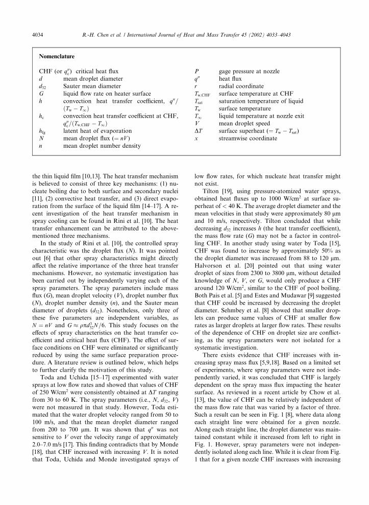
surface. As reviewed in a recent article by Chow et al.
[13], the value of CHF can be relatively independent of
the mass flow rate that was varied by a factor of three.
Such a result can be seen in Fig. 1 [8], where data along
each straight line were obtained for a given nozzle.
Along each straight line, the droplet diameter was main-
tained constant while it increased from left to right in
Fig. 1. However, spray parameters were not indepen-
dently isolated along each line. While it is clear from Fig.
1 that for a given nozzle CHF increases with increasing
Nomenclature
CHF (or q00c ) critical heat flux
d mean droplet diameter
d32 Sauter mean diameter
G liquid flow rate on heater surface
h convection heat transfer coefficient, q00=ðTw � T1Þ
hc convection heat transfer coefficient at CHF,
q00c=ðTw;CHF � T1Þhfg latent heat of evaporation
N mean droplet flux (¼ nV )
n mean droplet number density
P gage pressure at nozzle
q00 heat flux
r radial coordinate
Tw;CHF surface temperature at CHF
Tsat saturation temperature of liquid
Tw surface temperature
T1 liquid temperature at nozzle exit
V mean droplet speed
DT surface superheat (¼ Tw � Tsat)
x streamwise coordinate
4034 R.-H. Chen et al. / International Journal of Heat and Mass Transfer 45 (2002) 4033–4043
G, same values of CHF can be obtained by using dif-
ferent nozzles that produce different values of G. This
indicates a strong dependence of the CHF on parame-
ters other than simply the mass flow rate.
To the authors’ knowledge, the study performed
herein is the first that independently varies each of V, N,
and d32 and assesses their contribution to spray cooling
heat transfer. It is noted that in this study all of these
spray parameters are ensemble averages. While this re-
port is concentrated on spray cooling in the nucleate
heat transfer regime, spray cooling also find applications
in cooling surfaces at temperatures above the Leiden-
frost point. A recent review on the progress in this area
can be found in Ref. [21]. Studies using mono-dispersed
droplets were previously conducted to investigate effects
of spray parameters on heat transfer, but were mostly
concerned with film boiling [22–24].
2. Experiment
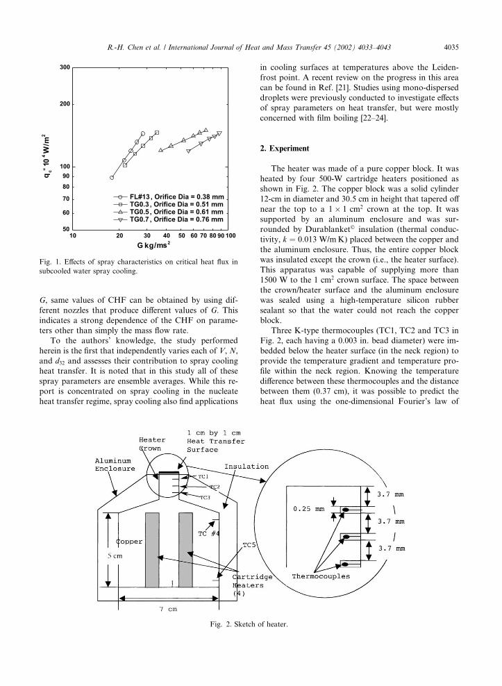
The heater was made of a pure copper block. It was
heated by four 500-W cartridge heaters positioned as
shown in Fig. 2. The copper block was a solid cylinder
12-cm in diameter and 30.5 cm in height that tapered off
near the top to a 1� 1 cm2 crown at the top. It was
supported by an aluminum enclosure and was sur-
rounded by Durablanket� insulation (thermal conduc-
tivity, k ¼ 0:013 W/mK) placed between the copper and
the aluminum enclosure. Thus, the entire copper block
was insulated except the crown (i.e., the heater surface).
This apparatus was capable of supplying more than
1500 W to the 1 cm2 crown surface. The space between
the crown/heater surface and the aluminum enclosure
was sealed using a high-temperature silicon rubber
sealant so that the water could not reach the copper
block.
Three K-type thermocouples (TC1, TC2 and TC3 in
Fig. 2, each having a 0.003 in. bead diameter) were im-
bedded below the heater surface (in the neck region) to
provide the temperature gradient and temperature pro-
file within the neck region. Knowing the temperature
difference between these thermocouples and the distance
between them (0.37 cm), it was possible to predict the
heat flux using the one-dimensional Fourier’s law of
Fig. 2. Sketch of heater.
Fig. 1. Effects of spray characteristics on critical heat flux in
subcooled water spray cooling.
R.-H. Chen et al. / International Journal of Heat and Mass Transfer 45 (2002) 4033–4043 4035
heat conduction. The distance between the heater sur-
face and TC1 is also 0.37 cm. The surface temperature
was determined by extrapolation using the measured
temperature gradient in the neck region specified by the
three thermocouples. Although the temperature of the
heater block changed as the heat input was increased
during the experiment, the temperature at the crown
reached a quasi-steady-state due to the fact that the
amount of heat stored in the crown region was very
small. This was verified by the fact that the heat flux
calculated from TC1 and TC2 readings was equal to that
calculated from TC2 and TC3 readings. Two thermo-
couples (TC4 and TC5 in Fig. 2) were placed on the
large part of the copper block to monitor the tempera-
tures so that an automatic shut-off of power could be
accomplished when the temperatures approached near
the operational limit (i.e., the softening point) of the
heater system. The softening points were 800 and 1000
�C for the cartridge heaters and copper, respectively. A
computer recorded the temperature measurements and
calculated the heat flux and the surface temperature.
Before fabricating the heater, a finite element analysis
of the steady-state heat conduction in the heater block
was performed, using a software package ANSYS, to
ensure (1) the softening points of the materials used were
not exceeded and (2) that the isotherms in the neck re-
gion were one-dimensional, allowing easy determination
of q00 and Tw.
For heat transfer experiments, the spray nozzle was
positioned directly above and perpendicular to the hori-
zontally placed heater surface. Water at room temper-
ature (T1 ¼ 25 �C) was pumped from a reservoir to the
spray nozzle. The nozzle pressure (P, in psig) produced
by a gear pump was read by a pressure gauge. Each
experiment (i.e., for one q00 vs. DT curve) was run with a
nozzle at a specific pressure and distance from the he-
ated surface. The experiment was conducted in the open
laboratory environment.
For this study, it is essential to satisfy the following
criteria. First, there needed to be large variations in N,
d32, and V so that a database could be constructed that
would contain nearly independent variation in each of
the spray parameters while keeping the other two in
narrow (i.e., nearly fixed) ranges. Secondly, it was nec-
essary that these parameters of interest were radially
uniform (i.e., one-dimensional) at known distances from
the nozzle exit. The values of N, d32, and V were mea-
sured using a Dantec PDPA system without the presence
of the heater. Effects of the presence of the heater were
discussed by Tilton [19], including complicated patterns
of liquid droplets rebounding from the surface. It is
noted that results of these cold spray measurements will
be different than those measured right above the heated
surface. However, these values are more practical to use
because one can design atomizers with spray parameters
that will optimize the spray cooling heat transfer. These
three spray parameters were determined for each com-
bination of the nozzle type, the nozzle pressure (P), and
the distance from the nozzle (x). It is noted that with the
same nozzle, the measured values of N and V were dif-
ferent at different distances. Droplet might also coalesce
in the flow direction, causing d32 to vary with x. How-
ever, relationships between d32 and x were outside of the
scope of this study. More than 3000 combinations of the
three spray parameters were obtained. However, only
subsets satisfying the above criteria were adopted for the
heat transfer experiment. The details for obtaining such
subsets are tedious and the reader is referred to Ref. [25].
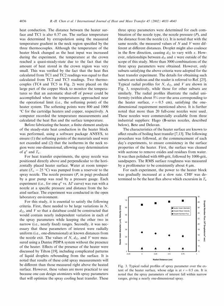
Typical radial profiles for N, d32, and V are shown in
Fig. 3, respectively, while those for other subsets are
similarly. The radial profiles illustrate the radial uni-
formity (within about 5% over the area corresponding to
the heater surface, r ¼ 0:5 cm), satisfying the one-
dimensional requirement mentioned above. It is further
noted that more than 20 full-cone nozzles were used.
These nozzles were commercially available from three
industrial suppliers: Hago (B-series nozzles, described
below), Bete and Delavan.
The characteristics of the heater surface are known to
affect results of boiling heat transfer [7,13]. The following
procedure was followed, at the commencement of each
day’s experiments, to ensure consistency in the surface
properties of the heater. First, the surface was cleaned
with acetone to remove oxides and residues from water.
It was then polished with 600-grit, followed by 1000-grit,
sandpapers. The RMS surface roughness was measured
by a profilometer to be consistently about 4 lm.
For each experiment, the power to the heater block
was gradually increased at a slow rate. CHF was de-
termined to be the heat flux above which excursion in Tw
Fig. 3. Typical radial profiles of spray parameter over the ex-
tent of the heater surface, whose edge is at r ¼ 0:5 cm. It is
noted that the spray parameters of interest fall within narrow
ranges, giving a nearly one-dimensional spray.
4036 R.-H. Chen et al. / International Journal of Heat and Mass Transfer 45 (2002) 4033–4043
occurred. When CHF was reached, the power to the
heater was turned off and the spray was continuously
supplied until the heater block cooled down to room
temperature. Then, a new combination of the nozzle, P,
and x was implemented and the above steps were re-
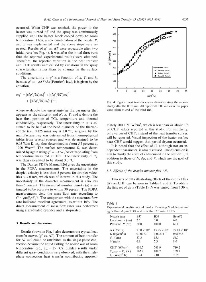
peated. Results of q00 vs. DT were repeatable after two
initial runs (see Fig. 4). It was after the initial three runs
that the reported experimental results were obtained.
Therefore, the reported variation in the heat transfer
and CHF results were caused by variations in the spray
characteristics rather than by changes in the surface
conditions.
The uncertainty in q00 is a function of x, T, and k,
because q00 ¼ �kDT=Dx (Fourier’s law). It is given by the
equation
xq00 ¼ ½ðoq00=oxÞxx2 þ ½ðoq00=oT ÞxT2
þ f½ðoq00=okÞxk 2g1=2;
where x denote the uncertainty in the parameter that
appears as the subscript and q00, x, T, and k denote the
heat flux, position of TCs, temperature and thermal
conductivity, respectively. The uncertainty in x is as-
sumed to be half of the bead diameter of the thermo-
couple (i.e., 0.125 mm). xT is 2.0 �C, as given by the
manufacturer. xk was determined from thermophysical
tables from several sources and was determined to be
0.05 W/mK. xq00 thus determined is about 5.5 percent at
1000 W/cm2. The surface temperature Tw was deter-
mined by again using q00 ¼ �kDT=Dx extrapolating from
temperature measured at TC1. The uncertainty of Tw
was then calculated to be about 3.0 �C.
The Dantec PDPA Manual [26] gives the uncertainty
in the PDPA measurements. The uncertainty in the
droplet velocity is less than 5 percent for droplet veloc-
ities > 4:0 m/s, which was of interest in this study. The
uncertainty in the diameter measurement is also less
than 5 percent. The measured number density (n) is es-
timated to be accurate to within 30 percent. The PDPA
measurements yield the mass flow rate according to
G � qpd332nV =6. The comparison with the measured flow
rate indicated excellent agreement, to within 10%. The
direct measurement of mass flow rates was performed
using a graduated cylinder and a stopwatch.
3. Results and discussion
Results shown in Fig. 4 also demonstrate typical heat
transfer curves (q00 vs. DT ). The amount of heat transfer
for DT ¼ 0 could be attributed to the single-phase con-
vection because the liquid exiting the nozzle was at room
temperature (i.e., T1 ¼ 25 �C). Similar results under
different spray conditions were observed, with the single-
phase convection heat transfer contributing approxi-
mately 200� 50 W/cm2, which is less than or about 1/3
of CHF values reported in this study. For simplicity,
only values of CHF, instead of the heat transfer curves,
will be reported. Visual inspection of the heater surface
near CHF would suggest that partial dryout occurred.
It is noted that the effect of G, although not an in-
dependent parameter, is also discussed. The discussion is
aim to clarify the effect of G discussed in the Section 1, in
addition to those of N, d32, and V, which are the goal of
this study.
3.1. Effects of the droplet number flux (N)
Two sets of data illustrating effects of the droplet flux
(N) on CHF can be seen in Tables 1 and 2. To obtain
the first set of data (Table 1), N was varied from 7:30 �
Fig. 4. Typical heat transfer curves demonstrating the repeat-
ability after the third run. All reported CHF values in this paper
were taken at end of the third run.
Table 1
Experimental conditions and results of varying N while keeping
d32 within 56 lm� 3% and V within 7:5 m=s� 10%
Nozzle type B37 B50 Bete#2
Location, x (cm) 2.5 3.0 6.0
Pressure, P (psi) 50.0 100.0 60.0
N (1/cm2 s) 7:30� 106 15:25� 106 29:00� 106
G (kg/cm2 s) 0.00072 0.00224 0.00248
d32 (lm) 57.3 55.4 54.7
V (m/s) 6.9 7.3 8.0
CHF (W/cm2) 610.7 761.9 780.2
Tw;CHF � T1 (K) 102.8 108.7 109.1
hc (W/cm2 K) 5.94 7.01 7.15
R.-H. Chen et al. / International Journal of Heat and Mass Transfer 45 (2002) 4033–4043 4037
106/cm2 s to 29:00� 106/cm2 s (by a factor of 4.2), while
d32 and V were kept in narrow ranges 56 lm� 2% and
7:5 m=s� 7%, respectively. It is seen that CHF in-
creased from 610.7 to 780.2 W/cm2, about 30%, over the
increase in N (see Table 1). The heat transfer coefficient
at CHF (hc ¼ q00CHF=ðTw;CHF � T1Þ), increased corre-
spondingly from 5.94 to 7.15 W/cmK, approximately
20%.
The second set of data is shown in Table 2, where N
was increased from 5:52� 106/cm2 s to 17:40� 106/cm2 s
and then to 18:83� 106/cm2 s (by a factor of about 3),
while d32 and V were kept in narrow ranges, 76 lm � 5%
and 10:5 m=s� 5%, respectively. The CHF can be seen
to increase with increasing N from 591.2 to 694.6 W/cm2
and then decrease slightly to 673.2 W/cm2. The decrease
falls within the experimental uncertainty of CHF. It can
therefore be said that CHF increased by approximately
15% as N was increased by a factor of 3. Similarly, hc
increased by approximately 15% from 5.86 to about 6.60
W/cm2 K (see Table 2). It can be concluded that in-
creasing N helps to increase CHF and hc.
In a study by Rini et al. [11] on saturated FC-72
spray cooling, a larger N leads to a larger q00. In that
study, V and d32 were kept within the range of 5–10%. It
was shown that as N was increased from 2:1� 106/cm2 s
to 8:3� 106/cm2 s, CHF increased from 67.0 W/cm2, by
approximately 20%, to 80.0 W/cm2, while hc increased
from 5.58 to 6.40 W/cm2, an increase of approximately
15%. The percent increase in CHF and hc are in good
agreement with that in Rini et al. [11], although values of
CHF and wetting capabilities of FC-72 and water are
different.
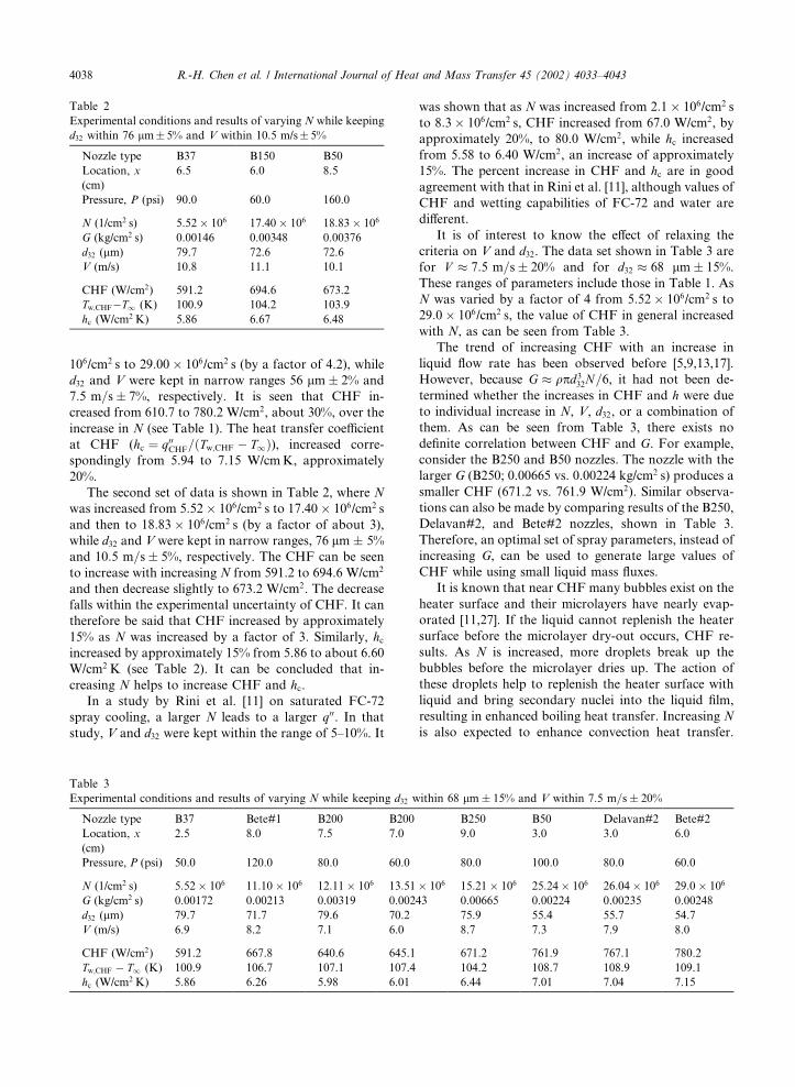
It is of interest to know the effect of relaxing the
criteria on V and d32. The data set shown in Table 3 are
for V � 7:5 m=s� 20% and for d32 � 68 lm� 15%.
These ranges of parameters include those in Table 1. As
N was varied by a factor of 4 from 5:52� 106/cm2 s to
29:0� 106/cm2 s, the value of CHF in general increased
with N, as can be seen from Table 3.
The trend of increasing CHF with an increase in
liquid flow rate has been observed before [5,9,13,17].
However, because G � qpd332N=6, it had not been de-
termined whether the increases in CHF and h were due
to individual increase in N, V, d32, or a combination of
them. As can be seen from Table 3, there exists no
definite correlation between CHF and G. For example,
consider the B250 and B50 nozzles. The nozzle with the
larger G (B250; 0.00665 vs. 0.00224 kg/cm2 s) produces a
smaller CHF (671.2 vs. 761.9 W/cm2). Similar observa-
tions can also be made by comparing results of the B250,
Delavan#2, and Bete#2 nozzles, shown in Table 3.
Therefore, an optimal set of spray parameters, instead of
increasing G, can be used to generate large values of
CHF while using small liquid mass fluxes.
It is known that near CHF many bubbles exist on the
heater surface and their microlayers have nearly evap-
orated [11,27]. If the liquid cannot replenish the heater
surface before the microlayer dry-out occurs, CHF re-
sults. As N is increased, more droplets break up the
bubbles before the microlayer dries up. The action of
these droplets help to replenish the heater surface with
liquid and bring secondary nuclei into the liquid film,
resulting in enhanced boiling heat transfer. Increasing N
is also expected to enhance convection heat transfer.
Table 2
Experimental conditions and results of varying N while keeping
d32 within 76 lm� 5% and V within 10.5 m/s� 5%
Nozzle type B37 B150 B50
Location, x
(cm)
6.5 6.0 8.5
Pressure, P (psi) 90.0 60.0 160.0
N (1/cm2 s) 5:52� 106 17:40� 106 18:83� 106
G (kg/cm2 s) 0.00146 0.00348 0.00376
d32 (lm) 79.7 72.6 72.6
V (m/s) 10.8 11.1 10.1
CHF (W/cm2) 591.2 694.6 673.2
Tw;CHF�T1 (K) 100.9 104.2 103.9
hc (W/cm2 K) 5.86 6.67 6.48
Table 3
Experimental conditions and results of varying N while keeping d32 within 68 lm� 15% and V within 7:5 m=s� 20%
Nozzle type B37 Bete#1 B200 B200 B250 B50 Delavan#2 Bete#2
Location, x
(cm)
2.5 8.0 7.5 7.0 9.0 3.0 3.0 6.0
Pressure, P (psi) 50.0 120.0 80.0 60.0 80.0 100.0 80.0 60.0
N (1/cm2 s) 5:52� 106 11:10� 106 12:11� 106 13:51� 106 15:21� 106 25:24� 106 26:04� 106 29:0� 106
G (kg/cm2 s) 0.00172 0.00213 0.00319 0.00243 0.00665 0.00224 0.00235 0.00248
d32 (lm) 79.7 71.7 79.6 70.2 75.9 55.4 55.7 54.7
V (m/s) 6.9 8.2 7.1 6.0 8.7 7.3 7.9 8.0
CHF (W/cm2) 591.2 667.8 640.6 645.1 671.2 761.9 767.1 780.2
Tw;CHF � T1 (K) 100.9 106.7 107.1 107.4 104.2 108.7 108.9 109.1
hc (W/cm2 K) 5.86 6.26 5.98 6.01 6.44 7.01 7.04 7.15
4038 R.-H. Chen et al. / International Journal of Heat and Mass Transfer 45 (2002) 4033–4043
Therefore, the overall effect of increasing N is to enhance
CHF.
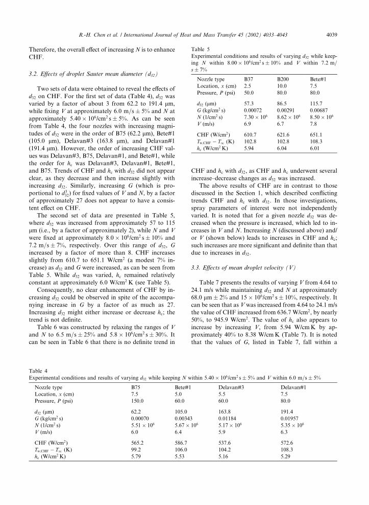
3.2. Effects of droplet Sauter mean diameter (d32)
Two sets of data were obtained to reveal the effects of
d32 on CHF. For the first set of data (Table 4), d32 was
varied by a factor of about 3 from 62.2 to 191.4 lm,
while fixing V at approximately 6:0 m=s� 5% and N at
approximately 5:40� 106/cm2 s� 5%. As can be seen
from Table 4, the four nozzles with increasing magni-
tudes of d32 were in the order of B75 (62.2 lm), Bete#1
(105.0 lm), Delavan#3 (163.8 lm), and Delavan#1
(191.4 lm). However, the order of increasing CHF val-
ues was Delavan#3, B75, Delavan#1, and Bete#1, while
the order for hc was Delavan#3, Delavan#1, Bete#1,
and B75. Trends of CHF and hc with d32 did not appear
clear, as they decrease and then increase slightly with
increasing d32. Similarly, increasing G (which is pro-
portional to d332) for fixed values of V and N, by a factor
of approximately 27 does not appear to have a consis-
tent effect on CHF.
The second set of data are presented in Table 5,
where d32 was increased from approximately 57 to 115
lm (i.e., by a factor of approximately 2), while N and V
were fixed at approximately 8:0� 106/cm2 s� 10% and
7:2 m=s� 7%, respectively. Over this range of d32, G
increased by a factor of more than 8. CHF increases
slightly from 610.7 to 651.1 W/cm2 (a modest 7% in-
crease) as d32 and G were increased, as can be seen from
Table 5. While d32 was varied, hc remained relatively
constant at approximately 6.0 W/cm2 K (see Table 5).
Consequently, no clear enhancement of CHF by in-
creasing d32 could be observed in spite of the accompa-
nying increase in G by a factor of as much as 27.
Increasing d32 might either increase or decrease hc; the
trend is not definite.
Table 6 was constructed by relaxing the ranges of V
and N to 6:5 m=s� 25% and 5:8� 106/cm2 s� 30%. It
can be seen in Table 6 that there is no definite trend in
CHF and hc with d32, as CHF and hc underwent several
increase–decrease changes as d32 was increased.
The above results of CHF are in contrast to those
discussed in the Section 1, which described conflicting
trends CHF and hc with d32. In those investigations,
spray parameters of interest were not independently
varied. It is noted that for a given nozzle d32 was de-
creased when the pressure is increased, which led to in-
creases in V and N. Increasing N (discussed above) and/
or V (shown below) leads to increases in CHF and hc;
such increases are more significant and definite than that
due to increases in d32.
3.3. Effects of mean droplet velocity (V)
Table 7 presents the results of varying V from 4.64 to
24.1 m/s while maintaining d32 and N at approximately
68.0 lm� 2% and 15� 106/cm2 s� 10%, respectively. It
can be seen that as V was increased from 4.64 to 24.1 m/s
the value of CHF increased from 636.7 W/cm2, by nearly
50%, to 945.9 W/cm2. The value of hc also appears to
increase by increasing V, from 5.94 W/cmK by ap-
proximately 40% to 8.38 W/cmK (Table 7). It is noted
that the values of G, listed in Table 7, fall within a
Table 4
Experimental conditions and results of varying d32 while keeping N within 5:40� 106/cm2 s� 5% and V within 6:0 m=s� 5%
Nozzle type B75 Bete#1 Delavan#3 Delavan#1
Location, x (cm) 7.5 5.0 5.5 7.5
Pressure, P (psi) 150.0 60.0 60.0 80.0
d32 (lm) 62.2 105.0 163.8 191.4
G (kg/cm2 s) 0.00070 0.00343 0.01184 0.01957
N (1/cm2 s) 5:51� 106 5:67� 106 5:17� 106 5:35� 106
V (m/s) 6.0 6.4 5.9 6.3
CHF (W/cm2) 565.2 586.7 537.6 572.6
Tw;CHF � T1 (K) 99.2 106.0 104.2 108.3
hc (W/cm2 K) 5.79 5.53 5.16 5.29
Table 5
Experimental conditions and results of varying d32 while keep-
ing N within 8:00� 106/cm2 s� 10% and V within 7:2 m=
s� 7%
Nozzle type B37 B200 Bete#1
Location, x (cm) 2.5 10.0 7.5
Pressure, P (psi) 50.0 80.0 80.0
d32 (lm) 57.3 86.5 115.7
G (kg/cm2 s) 0.00072 0.00291 0.00687
N (1/cm2 s) 7:30� 106 8:62� 106 8:50� 106
V (m/s) 6.9 6.7 7.8
CHF (W/cm2) 610.7 621.6 651.1
Tw;CHF � T1 (K) 102.8 102.8 108.3
hc (W/cm2 K) 5.94 6.04 6.01
R.-H. Chen et al. / International Journal of Heat and Mass Transfer 45 (2002) 4033–4043 4039
narrow range (within 5% of 0.0025 kg/cm2 s). Therefore,
the effect of V was completely isolated.
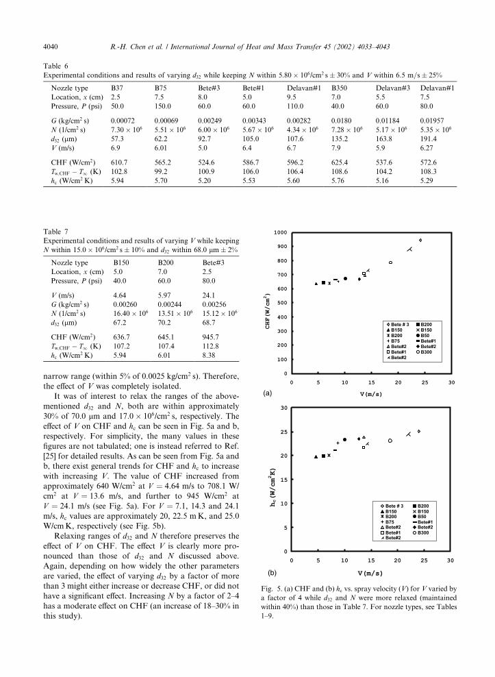
It was of interest to relax the ranges of the above-
mentioned d32 and N, both are within approximately
30% of 70.0 lm and 17:0� 106/cm2 s, respectively. The
effect of V on CHF and hc can be seen in Fig. 5a and b,
respectively. For simplicity, the many values in these
figures are not tabulated; one is instead referred to Ref.
[25] for detailed results. As can be seen from Fig. 5a and
b, there exist general trends for CHF and hc to increase
with increasing V. The value of CHF increased from
approximately 640 W/cm2 at V ¼ 4:64 m/s to 708.1 W/
cm2 at V ¼ 13:6 m/s, and further to 945 W/cm2 at
V ¼ 24:1 m/s (see Fig. 5a). For V ¼ 7:1, 14.3 and 24.1
m/s, hc values are approximately 20, 22.5 mK, and 25.0
W/cmK, respectively (see Fig. 5b).
Relaxing ranges of d32 and N therefore preserves the
effect of V on CHF. The effect V is clearly more pro-
nounced than those of d32 and N discussed above.
Again, depending on how widely the other parameters
are varied, the effect of varying d32 by a factor of more
than 3 might either increase or decrease CHF, or did not
have a significant effect. Increasing N by a factor of 2–4
has a moderate effect on CHF (an increase of 18–30% in
this study).
Table 6
Experimental conditions and results of varying d32 while keeping N within 5:80� 106/cm2 s� 30% and V within 6:5 m=s� 25%
Nozzle type B37 B75 Bete#3 Bete#1 Delavan#1 B350 Delavan#3 Delavan#1
Location, x (cm) 2.5 7.5 8.0 5.0 9.5 7.0 5.5 7.5
Pressure, P (psi) 50.0 150.0 60.0 60.0 110.0 40.0 60.0 80.0
G (kg/cm2 s) 0.00072 0.00069 0.00249 0.00343 0.00282 0.0180 0.01184 0.01957
N (1/cm2 s) 7:30� 106 5:51� 106 6:00� 106 5:67� 106 4:34� 106 7:28� 106 5:17� 106 5:35� 106
d32 (lm) 57.3 62.2 92.7 105.0 107.6 135.2 163.8 191.4
V (m/s) 6.9 6.01 5.0 6.4 6.7 7.9 5.9 6.27
CHF (W/cm2) 610.7 565.2 524.6 586.7 596.2 625.4 537.6 572.6
Tw;CHF � T1 (K) 102.8 99.2 100.9 106.0 106.4 108.6 104.2 108.3
hc (W/cm2 K) 5.94 5.70 5.20 5.53 5.60 5.76 5.16 5.29
Table 7
Experimental conditions and results of varying V while keeping
N within 15:0� 106/cm2 s� 10% and d32 within 68.0 lm� 2%
Nozzle type B150 B200 Bete#3
Location, x (cm) 5.0 7.0 2.5
Pressure, P (psi) 40.0 60.0 80.0
V (m/s) 4.64 5.97 24.1
G (kg/cm2 s) 0.00260 0.00244 0.00256
N (1/cm2 s) 16:40� 106 13:51� 106 15:12� 106
d32 (lm) 67.2 70.2 68.7
CHF (W/cm2) 636.7 645.1 945.7
Tw;CHF � T1 (K) 107.2 107.4 112.8
hc (W/cm2 K) 5.94 6.01 8.38
Fig. 5. (a) CHF and (b) hc vs. spray velocity (V) for V varied by
a factor of 4 while d32 and N were more relaxed (maintained
within 40%) than those in Table 7. For nozzle types, see Tables
1–9.
4040 R.-H. Chen et al. / International Journal of Heat and Mass Transfer 45 (2002) 4033–4043
From the above discussion, it is believed that a
combination of increased N and increased V would most
effectively enhance heat transfer and CHF. Increasing N
is expected to increase the number of secondary nuclei
[14]. This in turn leads to an increased nucleate heat
transfer, which is more effective than single-phase con-
vection. For a given N, droplets with larger V would
bring the entrained secondary nuclei closer to the heater
surface, enhancing the evaporation into the nuclei and
heat transfer. As a result of increasing V, the mixing and
convective heat transfer are also enhanced. This may
help to explain why increasing V is more effective than
increasingN in enhancing CHF. Because N ¼ nV , sprays
with larger V and smaller n result in higher values of
CHF than those with smaller V and larger n for a given
value of N.
3.4. Further results and discussion on the dominating effect
of droplet velocity (V)
Chow and co-workers [8,13] demonstrated that
smaller orifice nozzles provide larger values of CHF
than larger nozzles for similar flow rates. It was rea-
soned that, for a given flow rate, smaller droplets lead to
a larger value of Nd232 (which is / 1=d32 because N /
1=d332). Therefore, sprays from smaller nozzles create a
larger impact/wetted area per unit time on the surface,
which in turn prevents dry-out until a higher heat flux is
supplied to the surface. However, the effect of d32 in
increasing CHF appears to be insignificant, as discussed
above. Therefore, the enhancement of CHF is achiev-
able by increasing N based on Chow et al.’s reasoning,
which was already demonstrated above. If one is to fix
V, then an increase in N is accompanied by an increase
in G. Effects of G and N may therefore be inseparable.
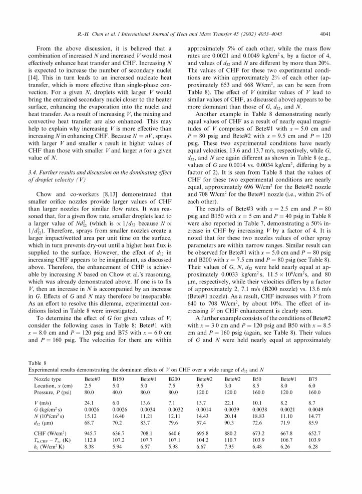
As an effort to resolve this dilemma, experimental con-
ditions listed in Table 8 were investigated.
To determine the effect of G for given values of V,
consider the following cases in Table 8: Bete#1 with
x ¼ 8:0 cm and P ¼ 120 psig and B75 with x ¼ 6:0 cm
and P ¼ 160 psig. The velocities for them are within
approximately 5% of each other, while the mass flow
rates are 0.0021 and 0.0049 kg/cm2 s, by a factor of 4,
and values of d32 and N are different by more than 20%.
The values of CHF for these two experimental condi-
tions are within approximately 2% of each other (ap-
proximately 653 and 668 W/cm2, as can be seen from
Table 8). The effect of V (similar values of V lead to
similar values of CHF, as discussed above) appears to be
more dominant than those of G, d32, and N.
Another example in Table 8 demonstrating nearly
equal values of CHF as a result of nearly equal magni-
tudes of V comprises of Bete#1 with x ¼ 5:0 cm and
P ¼ 80 psig and Bete#2 with x ¼ 9:5 cm and P ¼ 120
psig. These two experimental conditions have nearly
equal velocities, 13.6 and 13.7 m/s, respectively, while G,
d32, and N are again different as shown in Table 8 (e.g.,
values of G are 0.0014 vs. 0.0034 kg/cm2, differing by a
factor of 2). It is seen from Table 8 that the values of
CHF for these two experimental conditions are nearly
equal, approximately 696 W/cm2 for the Bete#2 nozzle
and 708 W/cm2 for the Bete#1 nozzle (i.e., within 2% of
each other).
The results of Bete#3 with x ¼ 2:5 cm and P ¼ 80
psig and B150 with x ¼ 5 cm and P ¼ 40 psig in Table 8
were also reported in Table 7, demonstrating a 50% in-
crease in CHF by increasing V by a factor of 4. It is
noted that for these two nozzles values of other spray
parameters are within narrow ranges. Similar result can
be observed for Bete#1 with x ¼ 5:0 cm and P ¼ 80 psig
and B200 with x ¼ 7:5 cm and P ¼ 80 psig (see Table 8).
Their values of G, N, d32 were held nearly equal at ap-
proximately 0.0033 kg/cm2 s, 11:5� 106/cm2s, and 80
lm, respectively, while their velocities differs by a factor
of approximately 2, 7.1 m/s (B200 nozzle) vs. 13.6 m/s
(Bete#1 nozzle). As a result, CHF increases with V from
640 to 708 W/cm2, by about 10%. The effect of in-
creasing V on CHF enhancement is clearly seen.
A further example consists of the conditions of Bete#2
with x ¼ 3:0 cm and P ¼ 120 psig and B50 with x ¼ 8:5cm and P ¼ 160 psig (again, see Table 8). Their values
of G and N were held nearly equal at approximately
Table 8
Experimental results demonstrating the dominant effects of V on CHF over a wide range of d32 and N
Nozzle type Bete#3 B150 Bete#1 B200 Bete#2 Bete#2 B50 Bete#1 B75
Location, x (cm) 2.5 5.0 5.0 7.5 9.5 3.0 8.5 8.0 6.0
Pressure, P (psi) 80.0 40.0 80.0 80.0 120.0 120.0 160.0 120.0 160.0
V (m/s) 24.1 6.0 13.6 7.1 13.7 22.1 10.1 8.2 8.7
G (kg/cm2 s) 0.0026 0.0026 0.0034 0.0032 0.0014 0.0039 0.0038 0.0021 0.0049
N (106/cm2 s) 15.12 16.40 11.21 12.11 14.43 20.14 18.83 11.10 14.77
d32 (lm) 68.7 70.2 83.7 79.6 57.4 90.3 72.6 71.9 85.9
CHF (W/cm2) 945.7 636.7 708.1 640.6 695.8 880.2 673.2 667.8 652.7
Tw;CHF � T1 (K) 112.8 107.2 107.7 107.1 104.2 110.7 103.9 106.7 103.9
hc (W/cm2 K) 8.38 5.94 6.57 5.98 6.67 7.95 6.48 6.26 6.28
R.-H. Chen et al. / International Journal of Heat and Mass Transfer 45 (2002) 4033–4043 4041
0.0038 kg/cm2 s and 19:5� 106/cm2 s, respectively. Al-
though the Bete#2 nozzle provides a slightly larger d32
(90.2 vs. 79.6 lm), this effect is expected to be insignificant
as discussed earlier. It is worth noting that the velocity
using the B50 nozzle is larger than that of the Bete#2
nozzle (22.1 vs. 10.1 m/s) and yields a CHF of 880W/cm2,
compared to 673 W/cm2 of the B50 nozzle.
The dominant effect of V on CHF shown in Table 7
and Fig. 5a, has again been demonstrated using Table 8
in the following two ways. First, keeping V nearly equal
while varying other spray parameters produced nearly
equal values of CHF. Secondly, varying V while keeping
other spray parameters nearly equal produced different
values of CHF.
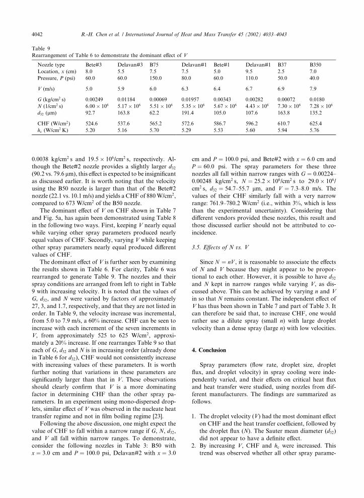
The dominant effect of V is further seen by examining
the results shown in Table 6. For clarity, Table 6 was
rearranged to generate Table 9. The nozzles and their
spray conditions are arranged from left to right in Table
9 with increasing velocity. It is noted that the values of
G, d32, and N were varied by factors of approximately
27, 3, and 1.7, respectively, and that they are not listed in
order. In Table 9, the velocity increase was incremental,
from 5.0 to 7.9 m/s, a 60% increase. CHF can be seen to
increase with each increment of the seven increments in
V, from approximately 525 to 625 W/cm2, approxi-
mately a 20% increase. If one rearranges Table 9 so that
each of G, d32 and N is in increasing order (already done
in Table 6 for d32), CHF would not consistently increase
with increasing values of these parameters. It is worth
further noting that variations in these parameters are
significantly larger than that in V. These observations
should clearly confirm that V is a more dominating
factor in determining CHF than the other spray pa-
rameters. In an experiment using mono-dispersed drop-
lets, similar effect of V was observed in the nucleate heat
transfer regime and not in film boiling regime [23].
Following the above discussion, one might expect the
value of CHF to fall within a narrow range if G, N, d32,
and V all fall within narrow ranges. To demonstrate,
consider the following nozzles in Table 3: B50 with
x ¼ 3:0 cm and P ¼ 100:0 psi, Delavan#2 with x ¼ 3:0
cm and P ¼ 100:0 psi, and Bete#2 with x ¼ 6:0 cm and
P ¼ 60:0 psi. The spray parameters for these three
nozzles all fall within narrow ranges with G ¼ 0:00224–0.00248 kg/cm2 s, N ¼ 25:2� 106/cm2 s to 29:0� 106/
cm2 s, d32 ¼ 54:7–55.7 lm, and V ¼ 7:3–8.0 m/s. The
values of their CHF similarly fall with a very narrow
range: 761.9–780.2 W/cm2 (i.e., within 3%, which is less
than the experimental uncertainty). Considering that
different vendors provided these nozzles, this result and
those discussed earlier should not be attributed to co-
incidence.
3.5. Effects of N vs. V
Since N ¼ nV , it is reasonable to associate the effects
of N and V because they might appear to be propor-
tional to each other. However, it is possible to have d32
and N kept in narrow ranges while varying V, as dis-
cussed above. This can be achieved by varying n and V
in so that N remains constant. The independent effect of
V has thus been shown in Table 7 and part of Table 3. It
can therefore be said that, to increase CHF, one would
rather use a dilute spray (small n) with large droplet
velocity than a dense spray (large n) with low velocities.
4. Conclusion
Spray parameters (flow rate, droplet size, droplet
flux, and droplet velocity) in spray cooling were inde-
pendently varied, and their effects on critical heat flux
and heat transfer were studied, using nozzles from dif-
ferent manufacturers. The findings are summarized as
follows.
1. The droplet velocity (V) had the most dominant effect
on CHF and the heat transfer coefficient, followed by
the droplet flux (N). The Sauter mean diameter (d32)did not appear to have a definite effect.
2. By increasing V, CHF and hc were increased. This
trend was observed whether all other spray parame-
Table 9
Rearrangement of Table 6 to demonstrate the dominant effect of V
Nozzle type Bete#3 Delavan#3 B75 Delavan#1 Bete#1 Delavan#1 B37 B350
Location, x (cm) 8.0 5.5 7.5 7.5 5.0 9.5 2.5 7.0
Pressure, P (psi) 60.0 60.0 150.0 80.0 60.0 110.0 50.0 40.0
V (m/s) 5.0 5.9 6.0 6.3 6.4 6.7 6.9 7.9
G (kg/cm2 s) 0.00249 0.01184 0.00069 0.01957 0.00343 0.00282 0.00072 0.0180
N (1/cm2 s) 6:00� 106 5:17� 106 5:51� 106 5:35� 106 5:67� 106 4:43� 106 7:30� 106 7:28� 106
d32 (lm) 92.7 163.8 62.2 191.4 105.0 107.6 163.8 135.2
CHF (W/cm2) 524.6 537.6 565.2 572.6 586.7 596.2 610.7 625.4
hc (W/cm2 K) 5.20 5.16 5.70 5.29 5.53 5.60 5.94 5.76
4042 R.-H. Chen et al. / International Journal of Heat and Mass Transfer 45 (2002) 4033–4043
ters were kept within narrow ranges or relaxed to
wider ranges.
3. Increasing N resulted in an increase in CHF and hc
when other parameters are kept in narrow ranges.
This general trend was also observed, with a few ex-
ceptions, when the range of other spray parameters
was relaxed. The exception can be attributed to, for
example, the fact that V is a dominant factor. A more
relaxed range of V would shift the effect being studied
from that of N to that of V.
4. To increase CHF for a given N, a dilute spray with
large droplet velocity appears to be more effective
than a dense spray with low velocities.
Acknowledgements
This research has been supported by the National
Science Foundation (NSF) Division of Chemical and
Thermal Systems (Grant numbers CTS-9813959 and
CTS-9616344).
References
[1] A. Bar-Cohen, State-of-the-art and trends in the thermal
packaging of electronic equipment, J. Electron. Packaging
114 (1992) 257–270.
[2] R.G. Waters, Diode laser degradation mechanisms: a
review, Prog. Quant. Electron. 15 (1983) 153–174.
[3] J. Yang, L.C. Chow, M.R. Pais, Nucleate boiling heat
transfer in spray cooling, J. Heat Transfer 118 (1996) 668–
671.
[4] X.Q. Chen, L.C. Chow, M.S. Sehmbey, Thickness of film
produced by a pressure atomizing nozzle, in: 30th AIAA
Thermophysics and Heat Transfer Conference, San Diego,
CA, Paper No. AIAA-95-2103, 1995.
[5] M.R. Pais, L.C. Chow, E.T. Mahefkey, Surface roughness
and its effect on the heat transfer mechanism in spray
cooling, J. Heat Transfer 114 (1992) 211–219.
[6] M.S. Sehmbey, L.C. Chow, O.J. Hahn, M.R. Pais, Effect of
spray characteristics on spray cooling with liquid nitrogen,
AIAA J. Thermophys. Heat Transfer 9 (1995) 757–765.
[7] M.S. Sehmbey, M.R. Pais, L.C. Chow, Effect of surface
material properties and surface characteristics in evapora-
tive spray cooling, AIAA J. Thermophys. Heat Transfer 6
(1992) 505–512.
[8] M.S. Sehmbey, L.C. Chow, O.J. Hahn, M.R. Pais, Spray
cooling of power electronics at cryogenic temperatures,
AIAA J. Thermophys. Heat Transfer 9 (1995) 123–128.
[9] K.A. Estes, I. Mudawar, Correlation of Sauter mean
diameter and critical heat flux for spray cooling of small
surfaces, Int. J. Heat Mass Transfer 38 (1995) 2985–2996.
[10] D.P. Rini, R.-H. Chen, L.C. Chow, Bubble behavior and
nucleate boiling heat transfer in saturated FC-72 spray
cooling, J. Heat Transfer 24 (2002) 63–72.
[11] D.P. Rini, R.-H. Chen, L.C. Chow, Bubble behavior and
heat transfer mechanism in FC-72 pool boiling, Exp. Heat
Transfer 14 (2001) 27–44.
[12] D. Nguyen, R.-H. Chen, L.C. Chow, C. Gu, Effects of
heater orientation and confinement on liquid nitrogen pool
boiling, AIAA J. Thermophys. Heat Transfer 14 (2000)
109–111.
[13] L.C. Chow, M.S. Sehmbey, M.R. Pais, High heat flux
spray cooling, Ann. Rev. Heat Transfer 8 (1997) 291–318.
[14] L.A. Kopchikov, G.I. Voronin, T.A. Kolach, D.A. La-
buntsov, P.D. Lebedev, Liquid boiling in a thin film, Int. J.
Heat Mass Transfer 12 (1969) 791–796.
[15] S. Toda, A study of mist cooling, 1st report: investigation
of mist cooling, Heat Transfer – Jpn. Res. 1 (1972) 39–50.
[16] S. Toda, A study of mist cooling, 2nd report: theory of mist
cooling and its fundamental experiments, Heat Transfer –
Jpn. Res. 3 (1974) 1–44.
[17] S. Toda, H. Uchida, Study of liquid film cooling with
evaporation and boiling, Heat Transfer – Jpn. Res. 2
(1973) 44–62.
[18] M. Monde, Critical heat flux in saturated forced convec-
tion boiling on a heated disk with impinging droplets, Heat
Transfer – Jpn. Res. 8 (1979) 54–64.
[19] D.E. Tilton, Spray cooling, Ph.D. Dissertation, University
of Kentucky, Lexington, KY, 1989.
[20] P.J. Halvorson, R.J. Carson, S.M. Jeter, S.I. Abdel-Khalik,
Critical heat flux limits for a heated surface impacted by a
stream of liquid droplets, J. Heat Transfer 116 (1994) 679–
685.
[21] S.C. Yao, Dynamics and heat transfer of impacting sprays,
Ann. Rev. Heat Transfer 5 (1994) 351–382.
[22] J.D. Bernardin, I. Mudawar, Film boiling heat transfer of
droplet streams and sprays, Int. J. Heat Mass Transfer 40
(1997) 2579–2593.
[23] S.C. Yao, K.J. Choi, Heat transfer experiments of mono-
dispersed vertically impacting sprays, Int. J. Multiphase
Flow 13 (1987) 639–648.
[24] K.J. Choi, S.C. Yao, Mechanisms of film boiling heat
transfer of normally impacting spray, Int. J. Heat Mass
Transfer 30 (1987) 311–318.
[25] J.E. Navedo, Parametric effects of spray characteristics on
spray cooling heat transfer, Ph.D. Dissertation, University
of Central Florida, Orlando, FL, 2000.
[26] Dantec PDPA Manual, Reproduced and Copyrighted by
Dantec Corporation, 1995.
[27] S. Nishio, T. Gotoh, N. Nagai, Observation of boiling
structure in high heat flux boiling, Int. J. Heat Mass
Transfer 41 (1998) 3191–3201.
R.-H. Chen et al. / International Journal of Heat and Mass Transfer 45 (2002) 4033–4043 4043