effects of glass fibres on the properties of micro … · if you believe that this document...
TRANSCRIPT

General rights Copyright and moral rights for the publications made accessible in the public portal are retained by the authors and/or other copyright owners and it is a condition of accessing publications that users recognise and abide by the legal requirements associated with these rights.
• Users may download and print one copy of any publication from the public portal for the purpose of private study or research. • You may not further distribute the material or use it for any profit-making activity or commercial gain • You may freely distribute the URL identifying the publication in the public portal
If you believe that this document breaches copyright please contact us providing details, and we will remove access to the work immediately and investigate your claim.
Downloaded from orbit.dtu.dk on: Dec 20, 2017
Effects of Glass Fibres on the Properties of Micro Moulded Plastic Parts
Islam, Aminul; Hansen, Hans Nørgaard; Gasparin, Stefania; Bondo, M.
Published in:Commercial Micro Manufacturing Magazine
Publication date:2011
Document VersionPublisher's PDF, also known as Version of record
Link back to DTU Orbit
Citation (APA):Islam, A., Hansen, H. N., Gasparin, S., & Bondo, M. (2011). Effects of Glass Fibres on the Properties of MicroMoulded Plastic Parts. Commercial Micro Manufacturing Magazine, 4(7).
ARTICLE
Effects of Glass Fibres on the Propertiesof Micro Moulded Plastic Parts
IntroductionIn the current state of injection mouldingtechnologies micro injection moulding is animmensely important process for industries andthe technology is growing at a rapid speed. Theneed for micro parts in the industries is on therise and the demand for tailor made materialswith specific parameters becomes larger. Oneeffective and economic way of mass productionfor micro parts is injection moulding and the usedmaterials for the process are mostly plasticsbecause of their suitability for injection moulding,good replication quality and cost. Nevertheless,plastic materials lack stiffness and mechanicalstrength. The most common way to improve themechanical properties of a plastic material is toadd glass fibres. Glass fibres improve the >
micro moulding
A. Islam, H. N. Hansen, S. Gasparin, Department of Mechanical Engineering,Technical University of Denmark and M. Bondo, Sonion A/S
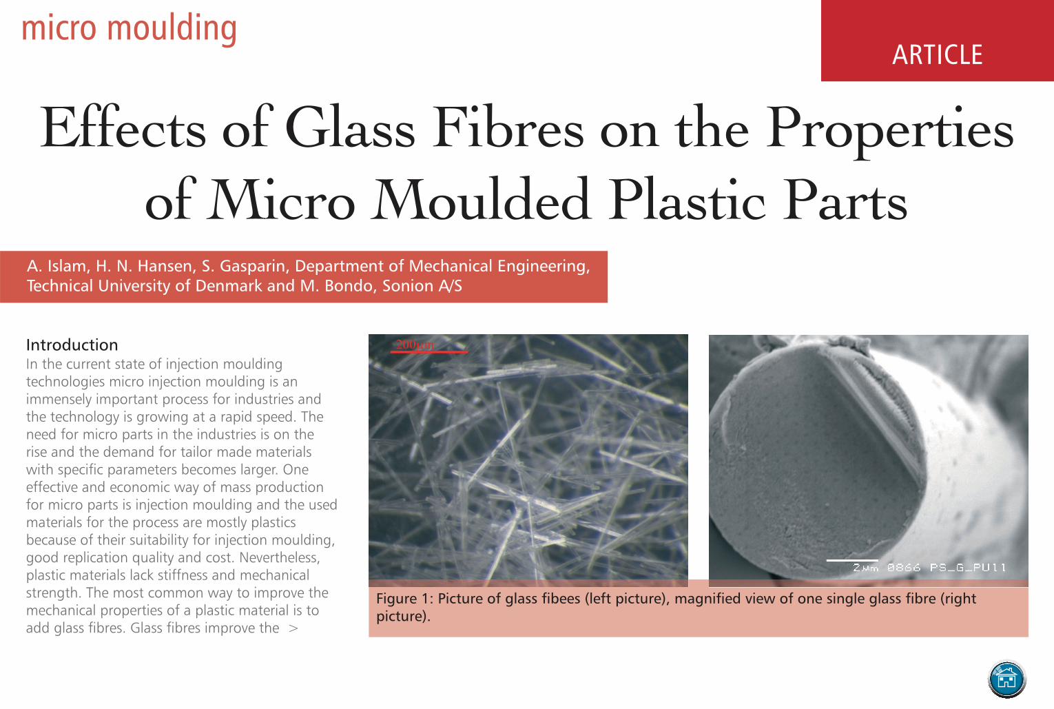
Figure 1: Picture of glass fibees (left picture), magnified view of one single glass fibre (rightpicture).

and surface finish, filling problems and so on. Theinvestigation carried out in thispaper reveals the effect of glassfibres on the replication qualityand surface properties of themicro moulded plastic parts.
ExperimentsThe aim of the current study is toinvestigate the effects of glassfibres on the replication quality ofthin polymeric ribs. The geometricalsize effect on the amount of glassfibre in the moulded plastic partswas also investigated in theexperiments.
Test geometryThe test specimen used for thisexperiment (shown in figure 2) was2.5 dimensional having long ribswith different aspect ratio. Differentrib thickness of this geometry willsimulate the different fillingbehaviour of the glass-filledmaterial. The section of the partshown with the red circle is termedas the critical section of the part asit has sharp corners and the thinnestcross section with an aspect ratio ofnine. >
structural properties like strength, stiffness andreduce the shrinkage of the part [1]. Glass fibresused in plastic materials are distinguished as shortglass fibres and long glass fibres. Typical lengthsof short glass fibres are 0.2 to 0.5 mm and forlong glass fibres, 10 to 15 mm. Short fibrereinforced thermoplastics are most commonlyused for injection moulding [2]. Although allthermoplastics can be reinforced with fibres,Polyamide, Polypropylene, Polystyrene, ABS andSAN are the most widely used fibre reinforcedmaterials in the plastic industries [2]. Figure 1shows the short glass fibres used withthermoplastic materials. The right picture of thefigure 1 shows the cross sections of an individualglass fibre. The pictures were taken by ScanningElectron Microscope during the experiment ofcurrent investigation.
Mechanical properties of glass fibre reinforcedplastics can vary depending on the fibredistribution, fibre orientation, fibre size, fibrefraction, fibre-plastic adhesion etc [2]. Glass fibresare used as reinforcing materials in many sectorslike automotive and naval industries, sportequipments, airplane industries and in manyother plastic industries. Glass fibres improve themechanical properties of plastic materials; on theother hand, they also impart some unwantedconditions and properties in the process and inthe product, especially for micro moulding andfor micro products, for example poor replication
Name Glass Manufacturer Moulding condition
Tmo Tme Vin
PS 158K 0% BASF 60°C 235°C 102 mm/s
PS 158KGf30 30% BASF 60°C 235°C 102 mm/s
Table 1: List of plastic materials.
Figure 2: Part geometry used in the experiment (criticalsection of the part is shown with the red circle).
click to view advertiser’s pageopens in new window

Plastic material used in the experiment Two commercial Polystyrene (PS) materials wereused for the experiment. The decision to choosePS material was down to the availability on thesame grade, with only difference in the contentof glass fibre. PS is also one of the commonlyused industrial thermoplastics. The specificationof the materials and their important injectionmoulding process parameters used in experimentare listed in table 1.
Moulding machine and processThe mould and machine used for the experimentare presented in the figure 3. The mouldingmachine was an Engel ES 80/25 HL-Victory andthe mould was produced by Wire ElectroDischarge Machining.
Result and analysisMechanical strengthAs mentioned before glass fibres increase themechanical strength of the moulded plastic parts.Injection moulding of ISO standard tensile barswith and without glass fibres confirms the effectof glass fibres on the mechanical strength of thematerials. The results are plotted in figure 4 and itshows there is a significant increase ofmechanical strength due to the addition of glassfibres.
The calculation shows that approximated increasein strength due to the addition of 30% fibres tothe PS material is 24%. Figure 5 shows thebroken surface of the moulded part after tensiletesting which shows that the broken surface is
smooth in case of non-filled material. The brokensurface with the glass filled material is veryirregular. This indicates that glass fibres actuallychange the fracture plane or slip plane of theplastic materials and dislocated it to make astronger failure surface [3].
Besides influencing the mechanical strength, glassfibres also decrease the elasticity of the materialand make it stiffer. For this reason, it can result incracks on the micro features of the part duringde-moulding like the crack visible in figure 6. Thepictures were taken on the critical sections of themoulded parts.
Surface qualityAddition of glass fibres increases the >
Figure 3: Injection moulding machine used formoulding of the plastic parts (left), and the moving sidemould with cavity (right).
Figure 4: Tensile testperformed on ISO standardtensile bars —samples aremade with and withoutglass fibres.
click to view advertiser’s pageopens in new window

roughness of the plastic parts. In the experiment,a big difference on the surface roughness of themoulded plastic parts was observed based on theglass fibres. The average surface roughnessmeasured on the moulded part with PS with glassfibre was about 7.84 μm and roughness of thepart moulded without glass fibre was about 2.58μm. The surface replication of PS without addedglass fibre is close to the actual mould surface. Inaddition, the glass fibre not only increased theaverage roughness but also the span between themaximum and minimum height of the samples isincreased [2].
A clear difference in the surface of the part isvisible based on the glass fibre in the material.The part with the glass fibre material is roughercompared to the other part surface. There is alsodifference in the edge sharpness and weld lineformation based on the amount of glass fibre inthe plastic materials. When a smooth surfaceand minimally visible weld line are desired,materials without glass fibres are recommended.Figure 8 shows the difference in replicationquality of the critical section of the part with andwithout glass-filled materials.
Fibre distribution and orientationTo investigate the amount of glass fibres and theirdirectional orientation at different sections ofmoulded part, the part moulded with glass filledPS material, was cut in three different sections(shown in figure 9): one was close to the gate;another one was far from the gate and one in themiddle where the critical sections are placed.
Each section was then grinded, and investigatedunder light optical microscope. Approximatelocation of the investigation is shown in thefollowing figure; the spot size was 325 μm × 250 μm. Pictures taken by light opticalmicroscope at three different sections are shownbelow.
It is clear that there is difference in thedistribution and amount of glass fibres, since allpictures have the same size and resolution.Approximate counts of glass fibres are 166, 88and 41. In the section close to the gate, the fibresare orientated along the longitudinal direction ofthe initial flow. Far from the gate, fibres are lessorganised. To calculate the exact area covered byglass at different sections of the moulded part,the software package Scanning Probe ImageProcessor (SPIP) was used. SPIP located andmapped the glass covered area as shown in figure11 and automatically calculated the total areaand the area covered by glass fibres. The >
Figure 5: Broken surface of PS moulded tensile bar after tensile testing (left hand side picture—taken on the sample with glass and right hand side picture —taken on the samples withoutglass).
click to view advertiser’s pageopens in new window

results are presented in table 2. It shows that there is a difference in thepercentage amount of glass fibres at various crosssections based on their distance from the gate.
To investigate the influence of micro geometry onthe distribution of glass fibres, the cross section ofthe thinnest rib (shown in figure 12) wasinvestigated again at three different sections basedon the distance from the gate. The glass fibredistribution can be seen in figure 12. There is alsoa difference in the amount of glass fibres based onthe location of the cross section (approximately 77,61, and 50). The amount of glass fibres in this thinrib is much smaller, than the amount of glassfound in the thick section of the part when theobservation was made on the same size of crosssectional area.
Same calculation was done with SPIP to determinethe exact area covered by glass. The mappedpicture by SPIP is presented in figure 13 and resultsare presented in table 3. These also agree with theprevious result found in case of thick rib. Thatmeans the fibre distribution is different at differentsections of the moulded part and depends on thedistance from the gate of the moulded specimen.
A separate investigation was conducted to find theeffect of injection moulding process on the lengthof glass fibres. Injection moulded PS parts weredissolved in solvents (in this case a combination >
Figure 6: Effects of glass fibres on micro cracks of the injection moulded plastic parts (Partwithout glass fibre — left, part with glass fibre — right).
Figure 7: 3D picture of the moulded surface (part surface with glass fibre, left, and part surfacewithout glass fibre, right).
click to view advertiser’s pageopens in new window

Figure 8: Surface of critical section of moulded part — PS without glass fibre (left) and PS with glass fibre (right).
click to view advertiser’s pageopens in new window

of Acetone and Tetrahydroflouside was used) andafterwards the liquid was filtrated to separate theglass fibres from the liquid. Then the length ofthe glass fibre was measured and the averagelength was about 400 μm and the averagediameter was about 10 μm. The samemeasurements were performed for the glassfibres collected from the plastic granulate andalmost no difference was observed. This suggeststhat there was no significant change in the lengthof glass fibres due to the injection mouldingoperation. Figure 14 shows the glass fibrescollected from the plastic granulate and from themoulded plastic part respectively.
Summary and conclusionFrom the investigations, it is visible that thedensity of glass fibres in different sections of theplastic part depends on the location of the gate.It is also visible that part geometry has influenceon the fibre distribution. The thinner a part orpart section is, the lesser amount of fibres isdistributed in the part or in the part section. This
non-homogeneous fibre distribution imparts non-symmetric mechanical properties in mouldedparts. The addition of glass fibres in the plasticincreases the material stiffness and the addedstiffness affects the material’s ability to be ejectedfrom the mould without creating permanentdefects on the specimen.
The results clearly show that if the same processcondition is used to mould plastic parts withplastic with and without glass fibre, the resultwill be different. The plastic without glass fibreachieves better surface quality, boardersharpness and filling. Unfilled material has amore homogeneous flow characteristic andbetter replication quality than glass filledmaterial. Based on the investigations of thecritical areas of the moulded specimens, it isconcluded that for micro structure replication,material without glass fibres is preferableespecially when a smooth surface finish andgood replication quality is required.
Figure 9: Picture showing different crosssections of the part for the investigation ofglass fibredistribution and orientation.
click to view advertiser’s pageopens in new window

Figure 10: Cross section of the part moulded with glass filled PS(Picture taken under the thick rib and at three different sectionsbased on the distance from the gate location).
Figure 12: Cross section of glass fibre samples (Picture taken underthe thin rib and at three different sections based on the distancefrom the gate location.
Figure 11: Pictures from glass covered area calculation by SPIP on thethree sections under the thick rib.
Figure 13: Pictures from glass covered area calculation by SPIP on thethree sections under the thin rib.
click to view advertiser’s pageopens in new window

References1. S. I. Shaharuddin; M. S Salit; “A review of theeffect of the moulding parameters on theperformance of polymeric composite injectionmoulding”, University Putra Malaysia, Departmentof Mechanical and Manufacturing Engineering,43400 Serdang, Selangor-MALAYSIA, Publishedin the Turkish Journal of Engineering andEnvironmental Science (2006).
2. C. Øllgaard; O. Sundberg, K. Vesth, “Effects ofglass fibers on the filling of polymeric thin ribs”,Report submitted to Department of MechanicalEngineering, Technical University of Denmark,June 2007.
3. A. Islam, “Two component micro injectionmoulding for moulded interconnect devices”,Ph.D. thesis, Department of MechanicalEngineering, Technical University of Denmark,ISBN no- 978-87-89502-75-5NTEC (2008).
4. J.L. Thomason, “The influence of fiber lengthand concentration on the properties of glass fiberreinforced polypropylene: 7. Interface strengthand fiber strain in injection moulded long fiber PPat high fiber content.OI:10.1016/j.compositesa.2006.01.007.Composites Part A: Applied Science andManufacturing.
5. Bernasconi, P. Davoli, A. Basile, A. Filippi,“Effects of fiber orientation on the fatiguebehavior of fiber reinforced polyamide-6.International Journal of Fatigue. DOI:10.1016/j.ijdatigue.2006.04.001.
click to view advertiser’s pageopens in new window