ee175ab final report humanoid robot -...
TRANSCRIPT
SCATY
Dept. of Electrical Engineering, UCR
EE175AB Final Report: Humanoid Robot
March 14, 2016 & Version 1.0
1 of 110
EE175AB Final Report
Humanoid Robot
EE 175AB Final Report
Department of Electrical Engineering, UC Riverside
Project Team
Member(s)
Stanley Chang, Alberto Tam Yong
Date Submitted March 14, 2016
Section
Professor
Dr. Roman Chomko
Revision Revision 1.0
URL of Project
Wiki/Webpage
http://stanleyand.albertotech.com
Permanent Emails
of all team mem-
bers
Summary
This report presents the design and development of a low-cost humanoid
robot. The content within this document gives specific details regarding the
components of the product.
SCATY
Dept. of Electrical Engineering, UCR
EE175AB Final Report: Humanoid Robot
March 14, 2016 & Version 1.0
2 of 110
Revisions
Version Description of Version Author(s) Date
Completed
Approval
0.1 First draft – not ready to be released Stanley Chang,
Alberto Tam Yong
02/25/2016 Chomko
0.2 Needs formatting Stanley Chang,
Alberto Tam Yong
3/14/2016
1.0 Final Version Stanley Chang,
Alberto Tam Yong
03/14/2016
SCATY
Dept. of Electrical Engineering, UCR
EE175AB Final Report: Humanoid Robot
March 14, 2016 & Version 1.0
3 of 110
Table of Contents
REVISIONS .....................................................................................................................2
TABLE OF CONTENTS ....................................................................................................3
1 EXECUTIVE SUMMARY ...............................................................................................7
2 INTRODUCTION ...........................................................................................................8
2.1 DESIGN OBJECTIVES AND SYSTEM OVERVIEW ..........................................................8
2.2 BACKGROUNDS AND PRIOR ART ...............................................................................8 2.3 DEVELOPMENT ENVIRONMENT AND TOOLS ..............................................................9 2.4 RELATED DOCUMENTS AND SUPPORTING MATERIALS............................................10 2.5 DEFINITIONS AND ACRONYMS ................................................................................10
3 DESIGN CONSIDERATIONS ........................................................................................12
3.1 ASSUMPTIONS .........................................................................................................12 3.2 REALISTIC CONSTRAINTS ........................................................................................12
3.2.1 Weight/size Constraints ............................................................................................ 12 3.2.2 Technical and Skill Constraints ................................................................................ 12 3.2.3 Project Time and Budget Constraints ...................................................................... 12 3.2.4 End Product Price Constraints ................................................................................ 12
3.3 SYSTEM ENVIRONMENT AND EXTERNAL INTERFACES ............................................12
3.4 INDUSTRY STANDARDS ...........................................................................................13 3.5 KNOWLEDGE AND SKILLS .......................................................................................13 3.6 BUDGET AND COST ANALYSIS ................................................................................14
3.7 SAFETY ...................................................................................................................15 3.8 PERFORMANCE, SECURITY, QUALITY, RELIABILITY, AESTHETICS ETC. ..................15 3.9 DOCUMENTATION ...................................................................................................15 3.10 DESIGN METHODOLOGY .......................................................................................16 3.11 RISKS AND VOLATILE AREAS ................................................................................16
4 EXPERIMENT DESIGN AND FEASIBILITY STUDY ......................................................17
4.1 EXPERIMENT DESIGN ..............................................................................................17 4.1.1 Degrees of Freedoms - Lower Body ......................................................................... 17 4.1.2 Audio Recognition .................................................................................................... 17 4.1.3 Power Enable Module .............................................................................................. 18 4.1.4 Bluetooth Module ..................................................................................................... 18 4.1.5 Object Avoidance ..................................................................................................... 18 4.1.6 Text-to-Speech .......................................................................................................... 19 4.1.7 On-Board Computer for Computer Vision ............................................................... 19
4.2 EXPERIMENT RESULTS AND FEASIBILITY ................................................................19
5 ARCHITECTURE ........................................................................................................20
SCATY
Dept. of Electrical Engineering, UCR
EE175AB Final Report: Humanoid Robot
March 14, 2016 & Version 1.0
4 of 110
5.1 SYSTEM ARCHITECTURE .........................................................................................20 5.2 RATIONALE AND ALTERNATIVES ............................................................................20
6 HIGH LEVEL DESIGN ................................................................................................21
6.1 CONCEPTUAL VIEW .................................................................................................21 6.2 HARDWARE .............................................................................................................21
6.2.1 3D-Printed Frame: ................................................................................................... 21 6.2.2 Raspberry Pi 2: ........................................................................................................ 21 6.2.3 Dynamixel XL-320 Motors: ...................................................................................... 21 6.2.4 Charging PCB: ......................................................................................................... 22 6.2.5 SG90 Motor Control: ............................................................................................... 22 6.2.6 Teensy 3.2 ................................................................................................................. 22 6.2.7 EasyVR: .................................................................................................................... 22 6.2.8 Bluetooth nRF8001: ................................................................................................. 22 6.2.9 Ultrasonic Distance Sensor HC-SR04: .................................................................... 22 6.2.10 Accelerometer ADXL337: ...................................................................................... 22 6.2.11 Amplifier: ................................................................................................................ 22
6.3 SOFTWARE ..............................................................................................................22 6.3.1 Python on Raspberry Pi 2: ....................................................................................... 22 6.3.2 Arduino IDE: ............................................................................................................ 22 6.3.3 Processing: ............................................................................................................... 23
7 DATA STRUCTURES ...................................................................................................24
7.1 INTERNAL SOFTWARE DATA STRUCTURE .................................................................24 7.2 GLOBAL DATA STRUCTURE .....................................................................................25
7.3 TEMPORARY DATA STRUCTURE ...............................................................................26 7.4 DATABASE DESCRIPTIONS .......................................................................................26
8 LOW LEVEL DESIGN .................................................................................................27
8.1 POWER MANAGEMENT ............................................................................................30 8.1.1 Voltage Regulation ................................................................................................... 30 8.1.2 Battery Charging ...................................................................................................... 30
8.2 CONTROLLERS ........................................................................................................32 8.2.1 Ground Station ......................................................................................................... 32 8.2.2 Mobile Device ........................................................................................................... 32
8.3 CENTRAL PROCESSING ............................................................................................33 8.3.1 Distance Sensing ...................................................................................................... 34 8.3.2 Object Recognition and Text-to-Speech ................................................................... 34 8.3.3 Motor Control ........................................................................................................... 35 8.3.4 Audio Recognition .................................................................................................... 37 8.3.5 Main MCU ................................................................................................................ 38 8.3.6 Wireless Transceiver ................................................................................................ 40
8.4 MECHANICAL ..........................................................................................................40 8.4.1 Lower Body ............................................................................................................... 40 8.4.2 Upper Body ............................................................................................................... 40
8.5 AESTHETIC ..............................................................................................................40 8.5.1 Face .......................................................................................................................... 41
SCATY
Dept. of Electrical Engineering, UCR
EE175AB Final Report: Humanoid Robot
March 14, 2016 & Version 1.0
5 of 110
9 USER INTERFACE DESIGN ........................................................................................42
9.1 APPLICATION CONTROL ..........................................................................................42
9.2 INTERFACE ..............................................................................................................42 9.2.1 Interface 1: Mobile Bluetooth Application ............................................................... 42 9.2.2 Interface 2: GUI ....................................................................................................... 42 9.2.3 Interface 3: Voice Recognition ................................................................................. 42
9.3 DEVELOPMENT SYSTEM AND COMPONENTS AVAILABLE ..........................................42
10 EXPERIMENT DESIGN AND TEST PLAN ..................................................................43
10.1 DESIGN OF EXPERIMENTS ......................................................................................43 10.1.1 Standing on its own ................................................................................................ 43 10.1.2 Experiment 2: Walking ........................................................................................... 43 10.1.3 Experiment 3: Robot Movements ............................................................................ 43 10.1.4 Experiment 4: Manual Control via Bluetooth ........................................................ 44 10.1.5 Experiment 5: Visual Object Recognition ............................................................. 44 10.1.6 Experiment 6: Object Avoidance ............................................................................ 44 10.1.7 Experiment 7: Text-to-Speech ................................................................................ 44 10.1.8 Experiment 8: Voice Commands ............................................................................ 45 10.1.9 Experiment 9: Face Detection ................................................................................ 45 10.1.10 Experiment 10: Sleep ............................................................................................ 45
10.2 BUG TRACKING .....................................................................................................46 10.3 QUALITY CONTROL ...............................................................................................46
10.4 PERFORMANCE BOUNDS ........................................................................................47 10.5 IDENTIFICATION OF CRITICAL COMPONENTS ..........................................................47 10.6 ITEMS NOT TESTED BY THE EXPERIMENTS ............................................................47
10.6.1 Pressure Sensor ...................................................................................................... 47 10.6.2 Battery Balancer ..................................................................................................... 47
11 EXPERIMENTAL RESULTS AND TEST REPORT .......................................................49
11.1 TEST ITERATION 1: STABILIZATION/STANDING .....................................................49 11.1.1 Test 1 ...................................................................................................................... 49 11.1.2 Test 2 ...................................................................................................................... 49 11.1.3 Test 3 ...................................................................................................................... 49
11.2 TEST ITERATION 2: WALKING ...............................................................................49 11.2.1 Test 1 ...................................................................................................................... 49 11.2.2 Test 2 ...................................................................................................................... 50 11.2.3 Test 3 ...................................................................................................................... 50
11.3 TEST ITERATION 3: ROBOT MOVEMENTS ..............................................................50 11.3.1 Test 1 ...................................................................................................................... 50
11.4 TEST ITERATION 4: MANUEL CONTROL VIA BLUETOOTH ......................................50 11.4.1 Test 1 ...................................................................................................................... 50
11.5 TEST ITERATION 5: VISUAL OBJECT RECOGNITION ...............................................51 11.5.1 Test 1 ...................................................................................................................... 51
11.6 TEST ITERATION 6: TEXT-TO-SPEECH ...................................................................51 11.6.1 Test 1 ...................................................................................................................... 51
11.7 TEST ITERATION 7: VOICE COMMANDS .................................................................51 11.7.1 Test 1 ...................................................................................................................... 51
SCATY
Dept. of Electrical Engineering, UCR
EE175AB Final Report: Humanoid Robot
March 14, 2016 & Version 1.0
6 of 110
11.7.2 Test 2 ...................................................................................................................... 52 11.8 TEST ITERATION 8: FACE DETECTION ...................................................................52
11.8.1 Test 1 ...................................................................................................................... 52 11.9 TEST ITERATION 9: BATTERY CHARGING ..............................................................52
12 CONCLUSION AND FUTURE WORK .........................................................................55
12.1 CONCLUSION .........................................................................................................55 12.2 FUTURE WORK ......................................................................................................56 12.3 ACKNOWLEDGEMENT ............................................................................................56
13 REFERENCES ...........................................................................................................57
14 APPENDICES ............................................................................................................58
14.1 APPENDIX A: PARTS LIST ......................................................................................58
14.2 APPENDIX B: HARDWARE TOOLS ..........................................................................59 14.3 APPENDIX C: SOFTWARE LIST ...............................................................................59 14.4 APPENDIX D: ARDUINO CODE FILES: ....................................................................60
14.4.1 SCATY_Humanoid_Robot_John_1.ino .................................................................. 60 14.4.2 Accelerometer.h ...................................................................................................... 68 14.4.3 BLE.h ...................................................................................................................... 69 14.4.4 Dynamixel.h ............................................................................................................ 71 14.4.5 EasyVR.h ................................................................................................................ 84 14.4.6 Head_Arms.h .......................................................................................................... 89 14.4.7 RPi.h ....................................................................................................................... 92 14.4.8 TFT.h ...................................................................................................................... 99 14.4.9 Ultrasonic.h .......................................................................................................... 104
14.5 APPENDIX E ........................................................................................................104 14.5.1 Python: picam_face_color_3_notext.py ............................................................... 104
14.6 APPENDIX F ........................................................................................................107 14.6.1 Processing: ee175a_slider_config_gui_1.pde...................................................... 107
SCATY
Dept. of Electrical Engineering, UCR
EE175AB Final Report: Humanoid Robot
March 14, 2016 & Version 1.0
7 of 110
1 Executive Summary
The goal of our project was to design and develop an open-source low-cost humanoid robot that
would benefit four different fields: education, research/academia, consumer electronics, and extreme en-
vironments. Our open sourced project will allow educators to use it as a tool to teach programing and
robotics, consumers to have an advance and fun electronic machine to play with, and for researchers to
further advance the technology behind robotics. Overall, the complexity of the project can be divided into
two parts: the hardware, which is composed of diverse peripherals, and the software, which has a vast
amount of functions, variables, and complex relations.
The hardware within the system allows the robot to have human-like features and have the capa-
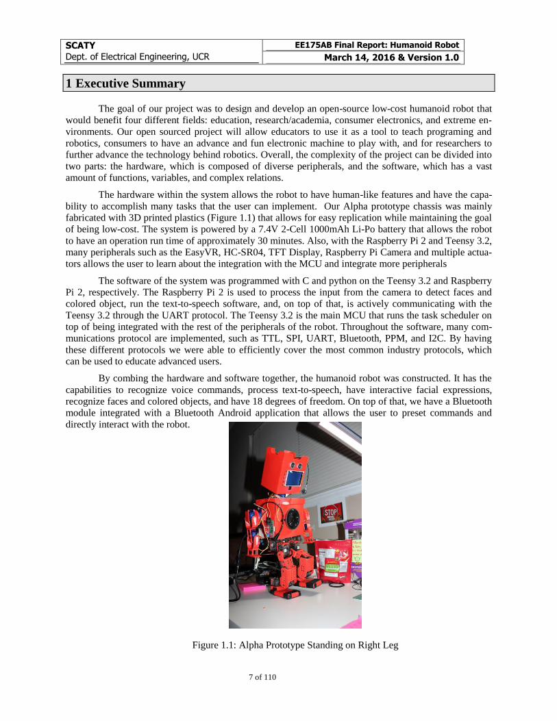
bility to accomplish many tasks that the user can implement. Our Alpha prototype chassis was mainly
fabricated with 3D printed plastics (Figure 1.1) that allows for easy replication while maintaining the goal
of being low-cost. The system is powered by a 7.4V 2-Cell 1000mAh Li-Po battery that allows the robot
to have an operation run time of approximately 30 minutes. Also, with the Raspberry Pi 2 and Teensy 3.2,
many peripherals such as the EasyVR, HC-SR04, TFT Display, Raspberry Pi Camera and multiple actua-
tors allows the user to learn about the integration with the MCU and integrate more peripherals
The software of the system was programmed with C and python on the Teensy 3.2 and Raspberry
Pi 2, respectively. The Raspberry Pi 2 is used to process the input from the camera to detect faces and
colored object, run the text-to-speech software, and, on top of that, is actively communicating with the
Teensy 3.2 through the UART protocol. The Teensy 3.2 is the main MCU that runs the task scheduler on
top of being integrated with the rest of the peripherals of the robot. Throughout the software, many com-
munications protocol are implemented, such as TTL, SPI, UART, Bluetooth, PPM, and I2C. By having
these different protocols we were able to efficiently cover the most common industry protocols, which
can be used to educate advanced users.
By combing the hardware and software together, the humanoid robot was constructed. It has the
capabilities to recognize voice commands, process text-to-speech, have interactive facial expressions,
recognize faces and colored objects, and have 18 degrees of freedom. On top of that, we have a Bluetooth
module integrated with a Bluetooth Android application that allows the user to preset commands and
directly interact with the robot.
Figure 1.1: Alpha Prototype Standing on Right Leg
SCATY
Dept. of Electrical Engineering, UCR
EE175AB Final Report: Humanoid Robot
March 14, 2016 & Version 1.0
8 of 110
2 Introduction
The design of our robot was inspired by many of the humanoid robots currently available in the market. It
incorporates many branch of electrical engineering such as robotics, power, and embedded systems.
These branches allow the project to be developed in the most efficient method in a complex project.
2.1 Design Objectives and System Overview
The objective of our group is to design a bipedal humanoid that is capable of interacting with humans by
recognizing faces, responding to voice commands, and be able to express itself with speech. However,
our overall goal is to allow the humanoid to be used for educational purposes, research and academia,
consumer electronics, and be applicable in extreme environments.
The robot can be used to teach children and adults C programming along with the hardware and
software aspects of robotics. For research and academia, researchers can use the humanoid robot to test
new algorithms and theories in control systems, kinematics, motion planning, and robotics in general. As
a consumer electronics product, users can use the robot as it is for entertainment or can be combined for
educational and practical purposes, as an assistant.
We designed the robot with the following technical objectives. We planned for the robot to run on
batteries for an operation time of 30 minutes. The range of the wireless communication to be 3.3 meters,
or 10 feet. The structure of the robot to have 18 degrees of freedom, where 10 would be on the lower
body, 6 for the arms, and 2 for the head. For the object detection range, we designed it to detect objects
accurately from the range of 4 to 100 centimeters. On top of detecting obstacles, the robot would be able
to detect three different objects, which could be considered “toys” for the robot. The voice command was
programmed to recognize 25 different commands and would be paired with the text-to-speech, in which
the robot would speak in the English language.
This is a meaningful project for us because we both have strong interest in embedded systems and
robotics. This project incorporates electrical engineering by integrating courses from the Electrical Engi-
neering program at UC Riverside, such as introductory and intermediate embedded systems (EE/CS120B
and CS122A), data acquisition, instrumentation, and process control (EE128), electronic circuits
(EE100A/B), automatic control (EE132), and computer vision (EE146)
2.2 Backgrounds and Prior Art
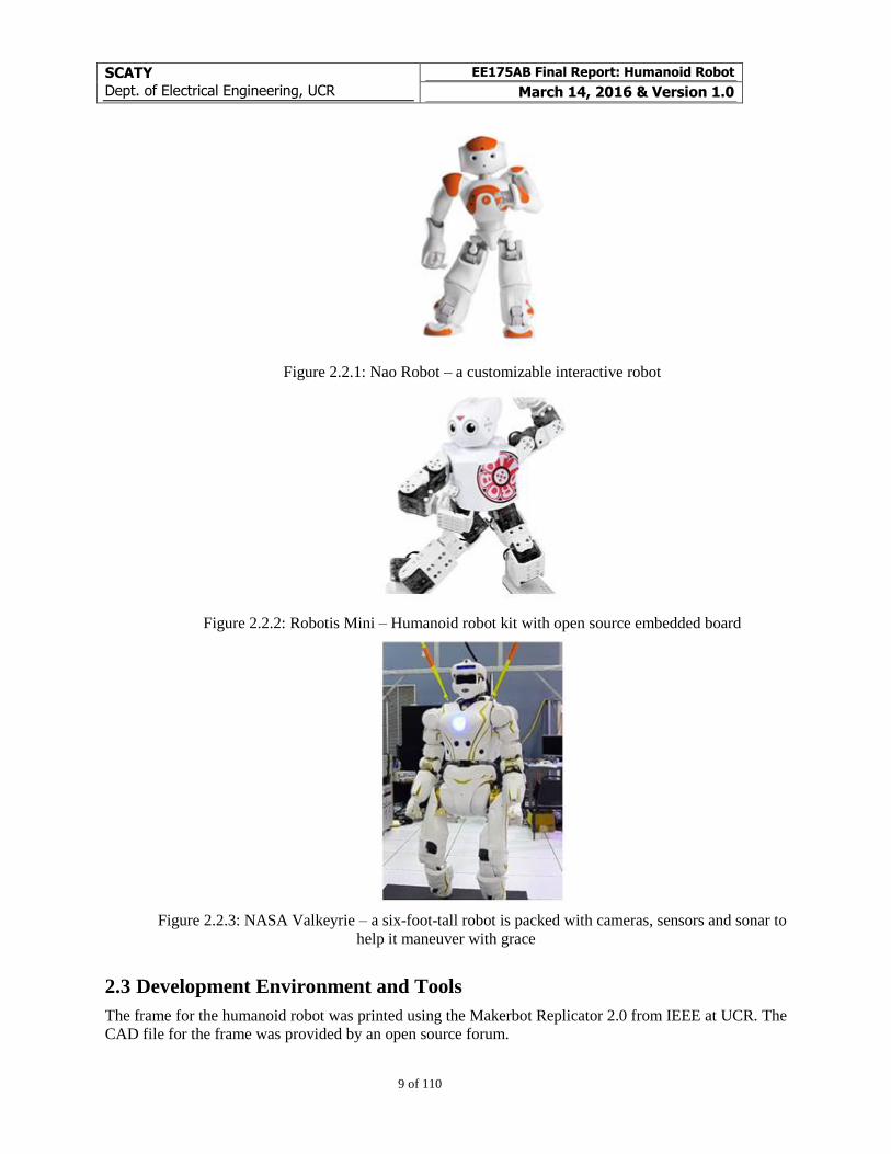
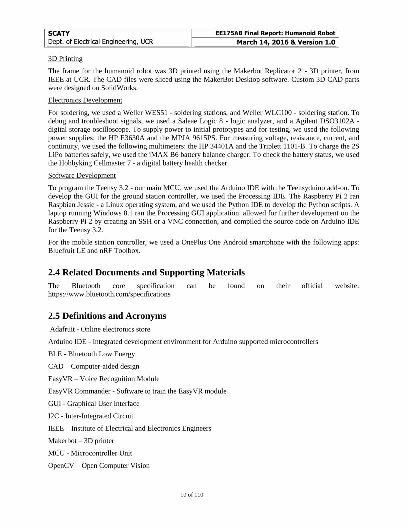
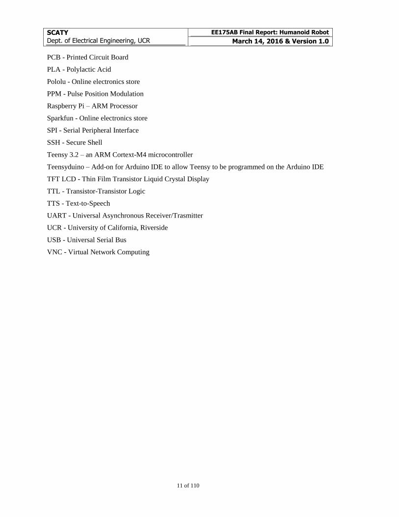
Several other humanoid robots are available in the market, such as the Nao Robot (see Figure 2.2.1), the
Robotis Mini (see Figure 2.2.2), and the NASA Valkerye (see Figure 2.2.3). The Nao Robot from Al-
deraban Robotics is a 58 cm humanoid robot, popular in academia and commercial industries. Currently,
the Nao robot can be acquired in North America for $7990. This robot has been widely used on the Ro-
bocup Competition - robot soccer competition. The Robotis Mini is a $500 humanoid robot designed for
the consumer electronic industry. By limiting the number of features, the Robotis Mini is able to set a
competitive price to open the humanoid robot market to middle-income families. The NASA Valkerye is
one of the latest humanoid robots designed by NASA to compete on the DARPA Robotics Challenge.
Inspired from previous humanoid robots designed by NASA, Valkerye packs some of the most advance
sensors and software packages developed for humanoid robots.
SCATY
Dept. of Electrical Engineering, UCR
EE175AB Final Report: Humanoid Robot
March 14, 2016 & Version 1.0
9 of 110
Figure 2.2.1: Nao Robot – a customizable interactive robot
Figure 2.2.2: Robotis Mini – Humanoid robot kit with open source embedded board
Figure 2.2.3: NASA Valkeyrie – a six-foot-tall robot is packed with cameras, sensors and sonar to
help it maneuver with grace
2.3 Development Environment and Tools
The frame for the humanoid robot was printed using the Makerbot Replicator 2.0 from IEEE at UCR. The
CAD file for the frame was provided by an open source forum.
SCATY
Dept. of Electrical Engineering, UCR
EE175AB Final Report: Humanoid Robot
March 14, 2016 & Version 1.0
10 of 110
3D Printing
The frame for the humanoid robot was 3D printed using the Makerbot Replicator 2 - 3D printer, from
IEEE at UCR. The CAD files were sliced using the MakerBot Desktop software. Custom 3D CAD parts
were designed on SolidWorks.
Electronics Development
For soldering, we used a Weller WES51 - soldering stations, and Weller WLC100 - soldering station. To
debug and troubleshoot signals, we used a Saleae Logic 8 - logic analyzer, and a Agilent DSO3102A -
digital storage oscilloscope. To supply power to initial prototypes and for testing, we used the following
power supplies: the HP E3630A and the MPJA 9615PS. For measuring voltage, resistance, current, and
continuity, we used the following multimeters: the HP 34401A and the Triplett 1101-B. To charge the 2S
LiPo batteries safely, we used the iMAX B6 battery balance charger. To check the battery status, we used
the Hobbyking Cellmaster 7 - a digital battery health checker.
Software Development
To program the Teensy 3.2 - our main MCU, we used the Arduino IDE with the Teensyduino add-on. To
develop the GUI for the ground station controller, we used the Processing IDE. The Raspberry Pi 2 ran
Raspbian Jessie - a Linux operating system, and we used the Python IDE to develop the Python scripts. A
laptop running Windows 8.1 ran the Processing GUI application, allowed for further development on the
Raspberry Pi 2 by creating an SSH or a VNC connection, and compiled the source code on Arduino IDE
for the Teensy 3.2.
For the mobile station controller, we used a OnePlus One Android smartphone with the following apps:
Bluefruit LE and nRF Toolbox.
2.4 Related Documents and Supporting Materials
The Bluetooth core specification can be found on their official website:
https://www.bluetooth.com/specifications
2.5 Definitions and Acronyms
Adafruit - Online electronics store
Arduino IDE - Integrated development environment for Arduino supported microcontrollers
BLE - Bluetooth Low Energy
CAD – Computer-aided design
EasyVR – Voice Recognition Module
EasyVR Commander - Software to train the EasyVR module
GUI - Graphical User Interface
I2C - Inter-Integrated Circuit
IEEE – Institute of Electrical and Electronics Engineers
Makerbot – 3D printer
MCU - Microcontroller Unit
OpenCV – Open Computer Vision
SCATY
Dept. of Electrical Engineering, UCR
EE175AB Final Report: Humanoid Robot
March 14, 2016 & Version 1.0
11 of 110
PCB - Printed Circuit Board
PLA - Polylactic Acid
Pololu - Online electronics store
PPM - Pulse Position Modulation
Raspberry Pi – ARM Processor
Sparkfun - Online electronics store
SPI - Serial Peripheral Interface
SSH - Secure Shell
Teensy 3.2 – an ARM Cortext-M4 microcontroller
Teensyduino – Add-on for Arduino IDE to allow Teensy to be programmed on the Arduino IDE
TFT LCD - Thin Film Transistor Liquid Crystal Display
TTL - Transistor-Transistor Logic
TTS - Text-to-Speech
UART - Universal Asynchronous Receiver/Trasmitter
UCR - University of California, Riverside
USB - Universal Serial Bus
VNC - Virtual Network Computing
SCATY
Dept. of Electrical Engineering, UCR
EE175AB Final Report: Humanoid Robot
March 14, 2016 & Version 1.0
12 of 110
3 Design Considerations
3.1 Assumptions
The end product is designed to be used in controlled environments. The field of bipedal humanoid robots
is still on an early stage, and this project aims to make bipedal humanoid robots more accessible by its
small size, low cost, and open sourced design.
3.2 Realistic Constraints
3.2.1 Weight/size Constraints
The weight and size of the robot need to be kept at the lowest possible because a bipedal humanoid robot
is designed to operate vertically. The actuators controlling the lower joints of the robot will require the
most torque. The robot will be designed to not be taller than 16 inches tall and lighter than 4 pounds. The
large amount of electromechanical and electronic components will need to be as small as possible to min-
imize the overall size of the robot.
3.2.2 Technical and Skill Constraints
This project involves the application of several topics that the Electrical Engineering program at the Uni-
versity of California, Riverside, cover in their curricula; however, this project requires to expand on the
materials covered in the standard curricula. The technical constraints include the implementation of mul-
tiple concurrent state machines, interfacing multiple peripherals with different communication protocols,
PID tuning, interfacing with diverse types of actuators, facial recognition, target tracking with a single
moving camera, and safe charging of 2S Lithium batteries with cell balancing. The mechanical and kine-
matic design of the robot also require a set of expertise our team does not feature.
3.2.3 Project Time and Budget Constraints
The project was given a 9-month design and development period with a 2-person team and a limited
budget of $500. The first 3 months were reserved for design development and the built of a proof-of-
concept while the following 6 months were designated to developing the first full prototype. Our largest
projected expense were the motors required to move the 20 joints in the robot.
3.2.4 End Product Price Constraints
One of the main goals of this project is to keep the end product price low; thus, the parts and components
used on the prototype need to be cost efficient.
3.3 System Environment and External Interfaces
The ground station remote controller code runs using the Processing IDE, which is available on Windows,
Mac OS, and Linux. All the same, the program can be compiled as a standalone software; however, it
would require a system with Java installed, to run.
The mobile station remote controller was tested on Android devices, but there are similar available solu-
tions on the App Store for iOS devices.
SCATY
Dept. of Electrical Engineering, UCR
EE175AB Final Report: Humanoid Robot
March 14, 2016 & Version 1.0
13 of 110
To update the firmware of the robot, a computer running the Arduino IDE must be set up with the Teen-
syduino Add-On and the other libraries stated on the Reference section of this manual.
3.4 Industry Standards
This project features I2C, SPI, and Bluetooth standards.
Communication between several peripherals within the robot used I2C and SPI standards.
Wireless communication with the robot is established using Bluetooth 4.0 standards, also known as Blue-
tooth Low Energy (BLE). Following the GATT service profiles, we are using the UART service to create
a virtual wireless UART connection between the robot and a remote controller.
3.5 Knowledge and Skills
This project required knowledge on embedded systems, computer vision, control systems, power man-
agement, electronic circuits, and electronic component acquisition.
This project required the following skills: EAGLE CAD PCB design and development, soldering, circuit
design, use of oscilloscopes, multi-meters, and power supplies, programming in C, C++, Python, Pro-
cessing, and Arduino.
Courses and Experience Related to this Project
Alberto
EE/CS 120B, CS 122A - Beginner and Intermediate Embedded systems
EE 1A/B - Engineering Circuit Analysis
CS 13 - Introduction to Computer Science for Engineering Majors
EE 100 A/B - Electronic Circuits
Previous Experience:
o SolidWorks
o Arduino
o Rapid Prototyping Techniques, such as 3D printing
Stanley:
EE 1A/B - Engineering Circuit Analysis
CS 10/12 - C++ Programming I/II
EE100 A/B - Electronic Circuits
EE/CS 120B, CS 122A - Beginner and Intermediate Embedded Systems
EE 128 - Data Acquisition, Instrumentation, and Process Control
Previous Experience:
o Arduino

SCATY
Dept. of Electrical Engineering, UCR
EE175AB Final Report: Humanoid Robot
March 14, 2016 & Version 1.0
14 of 110
New Knowledge and Skills
Communication and Control of Dynamixel 320 - smart servo motors, using TTL
OpenCV on Raspberry Pi
Python on Raspberry Pi
Target Tracking with Single Moving Camera
Control Systems for Multilink Robots
Text-to-Speech implementation
Voice Recognition implementation
Power Management for 2S (2-cell) Lithium-Ion Polymer Packs
3.6 Budget and Cost Analysis
By aiming to market this robot as a low-cost product, we set our budget to be $500.
Cost Analysis for Single Product
Qty Item Cost
10 Dynamixel XL-320 219.00
1 ROBOTIS Rivet Set 21.9
1 ROBOTIS Screw Set 2.90
1 EasyVR 3.0 38.25
1 Teensy 3.2 19.80
1 Red PLA 1.75 mm 22.98
1 Raspberry Pi 2 Model B 35.00
1 Raspberry Pi Camera 17.88
6 Micro Servo Motors SG90 15.00
2 LiPo 7.4V 2S 1000mAh 8.58
1 TFT 2.2" Display 320x240 8.00
2 6V 2.5A Step-Down Volt. Reg. 19.9
1 5V 1A Steo Down/Up Volt. Reg. 4.95
1 3.3V 1A Step Down/Up Volt. Reg. 5.95
1 PCA9685 LED Driver IC 2.54
1 HC-SR04 Ultrasonic Sensor 0.97
1 Sparkfun Mono Audio Amp 7.95
1 3.5mm Connector Breakout Board 0.99
1 Current Sensor ACS711EX -31A to 31A 3.95
1 Bluefruit LE - nRF8001 19.95
1 3-axis Accelerometer - ADXL337 9.95
SCATY
Dept. of Electrical Engineering, UCR
EE175AB Final Report: Humanoid Robot
March 14, 2016 & Version 1.0
15 of 110
1 Relay Board - srd-05vdc-sl-c 1.31
Miscellaneous Electronics 20.00
Sub Total $507.70
3.7 Safety
With the use of LiPo batteries, we have to ensure that the user charges the batteries properly. To do so, we
designed an on-board safe charging circuit that allowed the batteries cells to be properly balanced and
charged. We added a distance sensor onto the head to allow the robot to sense any obstruction in its path
to halts its movement to protect itself from getting damage and to keep users from getting harmed. To
safeguard from any potential bug, we have limited the range of motion from the actuators to avoid any
damages to the robot or users.
3.8 Performance, Security, Quality, Reliability, Aesthetics etc.
Performance: We want the overall performance of the robot to be enjoyable and promising. To achieve
this goal, we have to have extensively quality control to ensure that each component will work well to-
gether and have little to no errors while in operation.
Security: The design of our product ensures that users cannot unintentionally open up the body, which
houses the electronics and power system. Also due to the use of Li-Po batteries to power up our product,
we designed a safe charging circuit that will ensure the batteries cells are properly balanced and charged.
Quality Control: To ensure that the quality of our robot is exceptional, we extensively test each compo-
nent to determine whether or not it is fit to be used on our robot. Before we add any new hardware or
software to our design, each part must be tested and verified that it would work perfect with the overall
design.
Reliability: Ideally, the reliability of the robot should be top notch. With the application for research and
extreme environment, the robot should not fail in these environment as results would be inadmissible or
missions would fail if humans cannot retrieve the robot in the extreme environments. To test the reliabil-
ity of our robot, we would meticulously test each actions in multiple scenario and make adjustments until
we receive passing results.
Aesthetic: As our product has an intended use for consumer electronics, we have to create a design that
would catch consumer’s eyes, but at the same time be neutral to all audience. Another application that our
product would be for is educational. The design of the robot should be friendly enough to allow children
to be engaged and learn at the same time. To accomplish an aesthetically pleasing design, we designed the
3D printed body ourselves and designed the robot face on a TFT LCD Screen to look “cute”.
3.9 Documentation
To document the process of our senior design, we created a folder on Google Drive that contains all the
information regarding our project. Within the folder we created sub-folders to neatly organize our infor-
mation, such as: 3D-Printing, Code, Design Files, Final Report, Notes, Photo and Media, and Validation.
When we meet to discuss our progress, we created a Google Document with the corresponding date.
Within the document, we would take notes on what we have done, our goals, and our projected timeline
for each tasks. We have multiple documents containing notes on our trial-and-errors, validation tests, test
data and results, parts lists, and high-level design. For hand written documents and pictures, we scanned
the documents and uploaded them onto the drive. This protocol allowed us to have an electronic copy in
case a document got lost.
SCATY
Dept. of Electrical Engineering, UCR
EE175AB Final Report: Humanoid Robot
March 14, 2016 & Version 1.0
16 of 110
By having everything uploaded and documented on Google Drive, it gave us easy and fast access to our
past information. This also allowed us to compile everything into the final technical report with ease and
allowed easy access for others to view our files if needed.
3.10 Design Methodology
For our design methodology, we would first prototype and test independent systems to identify and trou-
bleshoot any initial bugs and design issues. After such development phase, the system would be proto-
typed on its final form, such as a prototyping board, PCB, or independently soldered wires. Then, we
would proceed to a partial system installation, which would involve interfacing several independent mod-
ules into a modular section of the project. After resolving any potential issues, a full system implementa-
tion and test would allow for a complete check of the designs.
3.11 Risks and Volatile Areas
Making the humanoid robot is one of the technical challenges that presents the most risk because it not
only involves electrical engineering but also a good understanding on mechanical engineering. For such,
we will attempt to tackle this challenge incrementally to evaluate and try to solve any design issues from
early on. All the same, we can foresee that the most difficult stage will be when all the load is installed on
the robot. Considering the limited time and financial resources, we will allocate a large portion of our
development schedule to solving this technical challenge avoiding to incur in further financial expense for
redesign.
SCATY
Dept. of Electrical Engineering, UCR
EE175AB Final Report: Humanoid Robot
March 14, 2016 & Version 1.0
17 of 110
4 Experiment Design and Feasibility Study
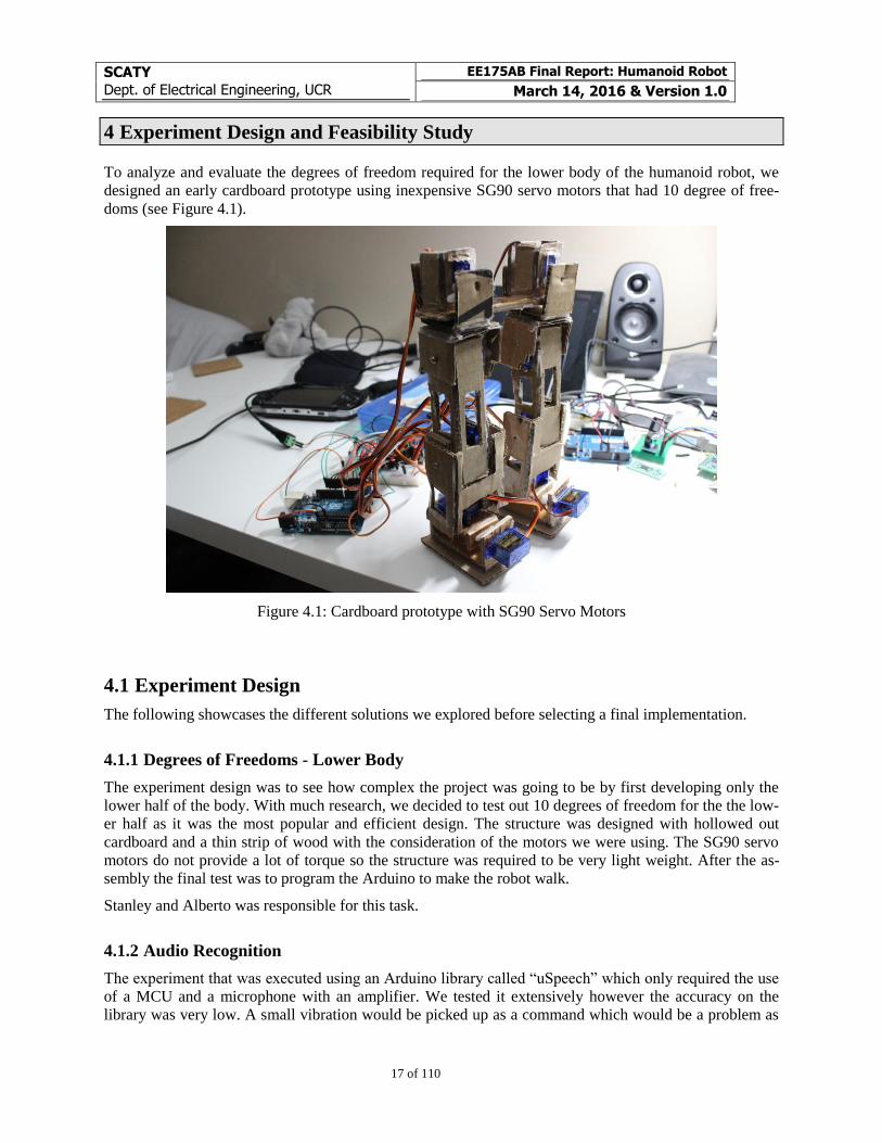
To analyze and evaluate the degrees of freedom required for the lower body of the humanoid robot, we
designed an early cardboard prototype using inexpensive SG90 servo motors that had 10 degree of free-
doms (see Figure 4.1).
Figure 4.1: Cardboard prototype with SG90 Servo Motors
4.1 Experiment Design
The following showcases the different solutions we explored before selecting a final implementation.
4.1.1 Degrees of Freedoms - Lower Body
The experiment design was to see how complex the project was going to be by first developing only the
lower half of the body. With much research, we decided to test out 10 degrees of freedom for the the low-
er half as it was the most popular and efficient design. The structure was designed with hollowed out
cardboard and a thin strip of wood with the consideration of the motors we were using. The SG90 servo
motors do not provide a lot of torque so the structure was required to be very light weight. After the as-
sembly the final test was to program the Arduino to make the robot walk.
Stanley and Alberto was responsible for this task.
4.1.2 Audio Recognition
The experiment that was executed using an Arduino library called “uSpeech” which only required the use
of a MCU and a microphone with an amplifier. We tested it extensively however the accuracy on the
library was very low. A small vibration would be picked up as a command which would be a problem as
SCATY
Dept. of Electrical Engineering, UCR
EE175AB Final Report: Humanoid Robot
March 14, 2016 & Version 1.0
18 of 110
the robot would have a lot vibration going through it with multiple actuators running. The main issue that
we decided to go with the EasyVR module and stop using the uSpeech library because the author indicat-
ed that the library should not be used with a real time scheduler.
Stanley and Alberto was responsible for this task.
4.1.3 Power Enable Module
The initial method we used was using the TIP31C NPN Transistor to act as a switch to allow the motors
to turn off and go to sleep mode. However the result of the design did not meet our expectation. The
thermal consideration as it would get really hot and had some difficulty supplying enough current to our
motors so we decided to switch over to a mechanical relay
Stanley was responsible for this task.
4.1.4 Bluetooth Module
The initial design of the product was using the HC-05 Bluetooth 2.0 module as it was cheap and efficient.
However, our MCU ran out of Serial ports so to rectify the problem, we decided to use a slightly more
expensive Bluetooth 4.0 module that communicated through SPI protocol. Also due to the change from
Bluetooth 2.0 to 4.0, the standards were not backward compatible so we had to change our method of
remote connection.
Stanley was responsible for this task.
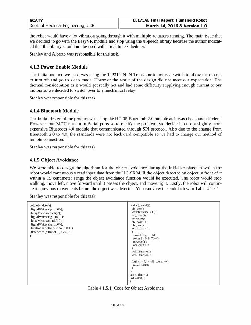
4.1.5 Object Avoidance
We were able to design the algorithm for the object avoidance during the initialize phase in which the
robot would continuously read input data from the HC-SR04. If the object detected an object in front of it
within a 15 centimeter range the object avoidance function would be executed. The robot would stop
walking, move left, move forward until it passes the object, and move right. Lastly, the robot will contin-
ue its previous movements before the object was detected. You can view the code below in Table 4.1.5.1.
Stanley was responsible for this task.
void obj_detc(){ digitalWrite(trig, LOW); delayMicroseconds(2); digitalWrite(trig, HIGH); delayMicroseconds(10); digitalWrite(trig, LOW); duration = pulseIn(echo, HIGH); distance = (duration/2) / 29.1; }
void obj_avoid(){ obj_detc(); while(distance < 15){ led_color(0); moveLeft(); obj_count++; obj_detc(); avoid_flag = 1; } if(avoid_flag == 1){ for(int i = 0; i< 7;i++){ moveLeft(); obj_count++; } walk_function(); walk_function(); for(int i = 0; i < obj_count; i++){ moveRight(); } } avoid_flag = 0; led_color(1); }
Table 4.1.5.1: Code for Object Avoidance
SCATY
Dept. of Electrical Engineering, UCR
EE175AB Final Report: Humanoid Robot
March 14, 2016 & Version 1.0
19 of 110
4.1.6 Text-to-Speech
Our first implementation for text-to-speech aimed to find an embedded solution to obtain low-
power consumption, low-cost, and an independent solution. The Speakjet was a sound synthesizer that
seemed to meet most of our criteria, except low-cost because of its $25 price tag. However, the quality of
the “speech” produced was very low, and it didn’t truly function as text-to-speech; instead, the Speakjet
required the specific pronunciation of words instead of simply converting strings of text to speech sounds.
After such, we evaluated for other solutions, giving higher priority to quality of sound because the
“speech” had to be understandable. We were only able to find a couple other available embedded solu-
tions, off-the-shelve, but one was designed for Chinese language while the other one cost more than $50.
Hence, we decided to explore using the Raspberry Pi 2 that we already had in our design considerations.
Within the Raspberry Pi 2, I tested the following solutions: eSpeak, Cepstral TTS, Pico TTS,
Google TTS, and Festival TTS. The quality of eSpeak was lower than desired. Cepstral TTS required a
licence, which would result troublesome on later development since we wanted to open sourced our de-
signs and files. Pico TTS had less support as it used to have, but I found instructions online to compile it
myself but it might be very time consuming. I couldn’t get Google TTS working as suggested by many
sources, but I noticed that the updated Terms and Conditions of the Google API deemed this solution in
violation of such. Festival TTS required a very simple installation, usage, and decent quality of speech.
Thus, I chose to use Festival TTS.
Alberto was responsible for this task.
4.1.7 On-Board Computer for Computer Vision
I have had experience working with the Raspberry Pi single-board computer and computer vision using
OpenCV, separately, but I had seen this implementation before and knew about its feasibility. We first
selected the Raspberry Pi Model A+ because of its size, lower power consumption, and cheaper price. All
the same, I worked on the development of the Python scripts and learned how to use the OpenCV package
on Python in the Raspberry Pi Model B+. After noticing how slow the system was, I decided to upgrade
our implementation to a Raspberry Pi 2 because of the featured quad core processor, making the computer
vision processing a lot smoother and giving us the option to use the Raspberry Pi 2 for other purposes,
too, such as Text-to-Speech.
Alberto was responsible for this task.
4.2 Experiment Results and Feasibility
The result of the experiment prove that the project was feasible and the project would be approved to the
next stage of prototyping. Our initial design proved that the robot must be light weight, however the SG90
servo motors would not be able to handle the stress and weight of an overall humanoid robot. This al-
lowed us to purchase stronger motors and come up with a more stable frame for the system. The end re-
sult for the next phase ended with the purchase of 10 Dynamixel XL-320 Smart Servo Motors to keep the
initial design of 10 degree of freedoms for the leg and then using the MakerBot to 3D print the frame as it
would be light weight and low cost.
SCATY
Dept. of Electrical Engineering, UCR
EE175AB Final Report: Humanoid Robot
March 14, 2016 & Version 1.0
20 of 110
5 Architecture
For the overall system architecture, refer to Section 6.1 for the High Level Design System’s Block Dia-
gram. All the same, several of the components are hidden inside the body of the robot to optimize for size
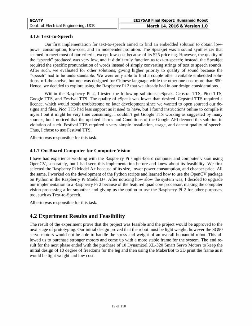
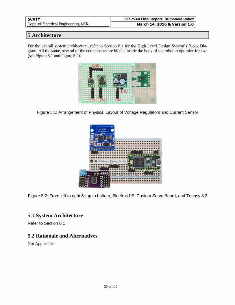
(see Figure 5.1 and Figure 5.2).
Figure 5.1: Arrangement of Physical Layout of Voltage Regulators and Current Sensor
Figure 5.2: From left to right & top to bottom, Bluefruit LE, Custom Servo Board, and Teensy 3.2
5.1 System Architecture
Refer to Section 6.1
5.2 Rationale and Alternatives
Not Applicable.
SCATY
Dept. of Electrical Engineering, UCR
EE175AB Final Report: Humanoid Robot
March 14, 2016 & Version 1.0
21 of 110
6 High Level Design
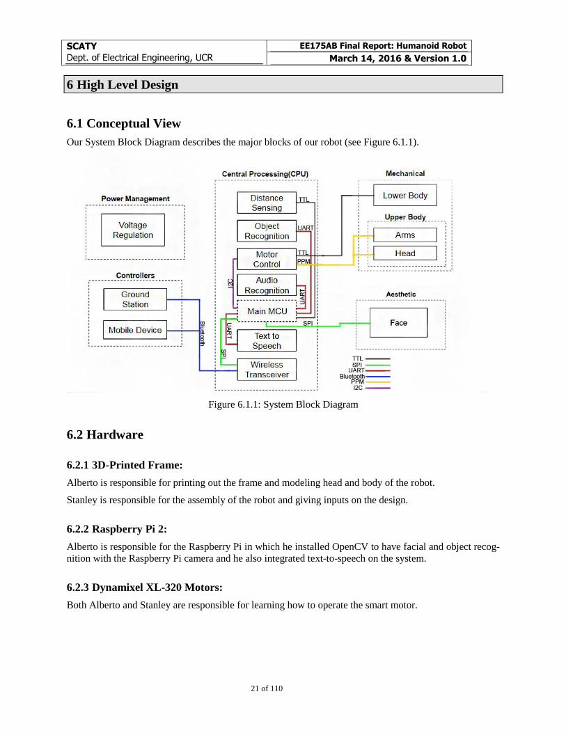
6.1 Conceptual View
Our System Block Diagram describes the major blocks of our robot (see Figure 6.1.1).
Figure 6.1.1: System Block Diagram
6.2 Hardware
6.2.1 3D-Printed Frame:
Alberto is responsible for printing out the frame and modeling head and body of the robot.
Stanley is responsible for the assembly of the robot and giving inputs on the design.
6.2.2 Raspberry Pi 2:
Alberto is responsible for the Raspberry Pi in which he installed OpenCV to have facial and object recog-
nition with the Raspberry Pi camera and he also integrated text-to-speech on the system.
6.2.3 Dynamixel XL-320 Motors:
Both Alberto and Stanley are responsible for learning how to operate the smart motor.
SCATY
Dept. of Electrical Engineering, UCR
EE175AB Final Report: Humanoid Robot
March 14, 2016 & Version 1.0
22 of 110
6.2.4 Charging PCB:
Alberto is responsible for creating the schematic and PCB to charge and balance the cells of the 2-cell Li-
Po battery.
6.2.5 SG90 Motor Control:
Alberto created a motor control using the PCA9685 to control different PWMs for all 8 SG90 motors we
have on the robot through I2C communications to save pins on the microcontroller. Stanley developed the
supporting functions to improve the control of all motors.
6.2.6 Teensy 3.2
Stanley and Alberto are responsible for programming the Teensy. Alberto wrote the code to integrate
communication through serial to send commands while Stanley wrote the code for the actions of the ro-
bot.
6.2.7 EasyVR:
Stanley is responsible for the voice recognition, in which he trained the module to recognize commands
and integrated the code to the Teensy.
6.2.8 Bluetooth nRF8001:
Stanley is responsible for Bluetooth communication with the robot and a smart device.
6.2.9 Ultrasonic Distance Sensor HC-SR04:
Stanley is responsible for the integration of the distance sensor to assist the robot detect objects
6.2.10 Accelerometer ADXL337:
Stanley is responsible for using the accelerometer to help the robot balance and walk.
6.2.11 Amplifier:
Alberto is responsible for the construction of the PCB and
6.3 Software
6.3.1 Python on Raspberry Pi 2:
Alberto is responsible for installing and developing scripts in Python, using, OpenCV for facial and object
recognition, and Festival TTS, for text-to-speech, for the Raspberry Pi 2.
6.3.2 Arduino IDE:
Stanley is responsible for programming the Teensy for the actions of the robot and the voice recognition.

SCATY
Dept. of Electrical Engineering, UCR
EE175AB Final Report: Humanoid Robot
March 14, 2016 & Version 1.0
23 of 110
6.3.3 Processing:
Alberto designed a GUI to assist the movement of the Dynamixel XL320 motors to help with the algo-
rithm of walking.
SCATY
Dept. of Electrical Engineering, UCR
EE175AB Final Report: Humanoid Robot
March 14, 2016 & Version 1.0
24 of 110
7 Data Structures
Our main focus for software development involved developing the code for the Teensy 3.2 on the Ar-
duino IDE. We organized the code by a main file and files for the different major peripherals on our sys-
tem, so our file structure is:
SCATY_Humanoid_Robot_John_1.ino
o Main file that contains the inclusion of libraries, objects, global variable declarations, and
the Task Scheduler
Accelerometer.ino
o Contains the core functions to read from the accelerometer
BLE.ino
o Contains the initiation and listening function to receive incoming commands
Dynamixel.ino
o Includes string parsing functions, functions to control the Dynamixel XL-320 smart servo
motors, PID, and the menu interface for manual control
EasyVR.ino
o Contains the initiation and state machine for the EasyVR module
Head_Arms.ino
o Contains the initiation for I2C, helping functions for the SG90 servo motors, and the state
machine for adjusted motor updates
RPi.ino
o Includes the helping functions for the Teensy 3.2 to interact with the Raspberry Pi 2 and
the state machine to receive and transmit data between these two devices
TFT.ino
o Contains the initiation for the TFT display, helping functions to animate the face expres-
sions of the robot, and the state machine to cycle through the different modes
Ultrasonic.ino
o Includes the initiation and reading functions for the HC-SR04 ultrasonic sensor
7.1 Internal software data structure
Inputs:
Accelerometer readings
o Acquired on Accelerometer.ino
BLE incoming commands
o Acquired on BLE.ino
EasyVR
o Acquired on EasyVR.ino
RPi Stream
o Acquired in SM4_Tick_RPi() within RPi.ino
Ultrasonic
o Acquired in Ultrasonic.ino
Processing:
Task Scheduler
o Located in SCATY_Humanoid_Robot_John_1.ino
SCATY
Dept. of Electrical Engineering, UCR
EE175AB Final Report: Humanoid Robot
March 14, 2016 & Version 1.0
25 of 110
Command Menu Interface
o In the form of command_menu(char) in Dynamixel.ino
Servo State Machine
o In the form of servo_write() in Head_Arms.ino
RPi Parsing State Machine
o In the form of SM4_Tick_RPi() within RPi.ino
TFT State Machine
o In the form of SM2_Tick_TFT() in TFT.ino
Outputs:
Dynamixel XL-320 Motors
SG90 Motors - Arms and Head
RPi Text-to-Speech
TFT Display
7.2 Global data structure
The Task Scheduler runs the following tasks with the following functions:
t1Callback_HeadCameraFollow()
o SM1_Tick_HeadCameraFollow()
This function runs as a state machine for following objects with only the head by
using the input from the Raspberry Pi 2 and the pi camera
t2Callback_RPi()
o SM4_Tick_RPi()
This function runs as a state machine for receiving and transmitting information
to the Raspberry Pi 2
t3Callback_SPI()
o SM2_Tick_TFT()
This function runs as a state machine cycling through the facial expressions, in-
cluding blinking and changes in “moods”
o BLE_loop()
This function handles the Bluetooth 4.0 transmissions and collection of data
t4Callback_EASYVR()
o EasyVR_SM()
State machine handling the communications with the EasyVR 3.0 module
t5Callback_command()
o command_menu_loop()
Function waiting for manual commands from either Bluetooth 4.0 or EasyVR
t6Callback_servo()
o servo_write()
State machine that allows speed control of the SG90 servo motors
t7Callback_PID()
o dynamixel_PID_x()
Function that constantly runs PID to maintain the robot balanced
t8Callback_walkStep()
o walk_left_step()
State machine for the execution of a left step. This function is part of the devel-
opment phase for walking
SCATY
Dept. of Electrical Engineering, UCR
EE175AB Final Report: Humanoid Robot
March 14, 2016 & Version 1.0
26 of 110
7.3 Temporary data structure
Not applicable.
7.4 Database descriptions
Not applicable.
SCATY
Dept. of Electrical Engineering, UCR
EE175AB Final Report: Humanoid Robot
March 14, 2016 & Version 1.0
27 of 110
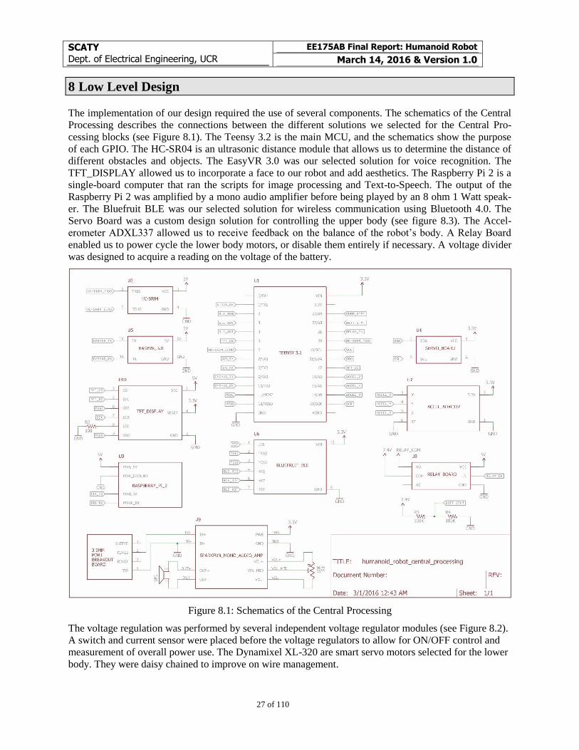
8 Low Level Design
The implementation of our design required the use of several components. The schematics of the Central
Processing describes the connections between the different solutions we selected for the Central Pro-
cessing blocks (see Figure 8.1). The Teensy 3.2 is the main MCU, and the schematics show the purpose
of each GPIO. The HC-SR04 is an ultrasonic distance module that allows us to determine the distance of
different obstacles and objects. The EasyVR 3.0 was our selected solution for voice recognition. The
TFT_DISPLAY allowed us to incorporate a face to our robot and add aesthetics. The Raspberry Pi 2 is a
single-board computer that ran the scripts for image processing and Text-to-Speech. The output of the
Raspberry Pi 2 was amplified by a mono audio amplifier before being played by an 8 ohm 1 Watt speak-
er. The Bluefruit BLE was our selected solution for wireless communication using Bluetooth 4.0. The
Servo Board was a custom design solution for controlling the upper body (see figure 8.3). The Accel-
erometer ADXL337 allowed us to receive feedback on the balance of the robot’s body. A Relay Board
enabled us to power cycle the lower body motors, or disable them entirely if necessary. A voltage divider
was designed to acquire a reading on the voltage of the battery.
Figure 8.1: Schematics of the Central Processing
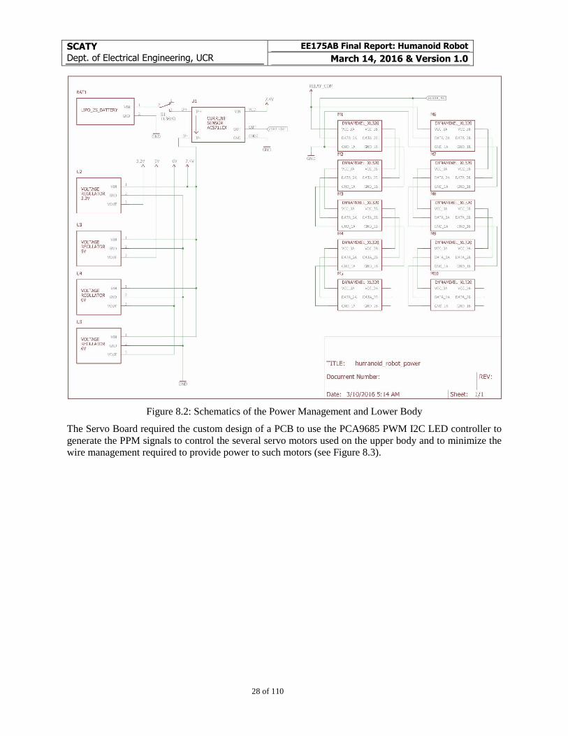
The voltage regulation was performed by several independent voltage regulator modules (see Figure 8.2).
A switch and current sensor were placed before the voltage regulators to allow for ON/OFF control and
measurement of overall power use. The Dynamixel XL-320 are smart servo motors selected for the lower
body. They were daisy chained to improve on wire management.
SCATY
Dept. of Electrical Engineering, UCR
EE175AB Final Report: Humanoid Robot
March 14, 2016 & Version 1.0
28 of 110
Figure 8.2: Schematics of the Power Management and Lower Body
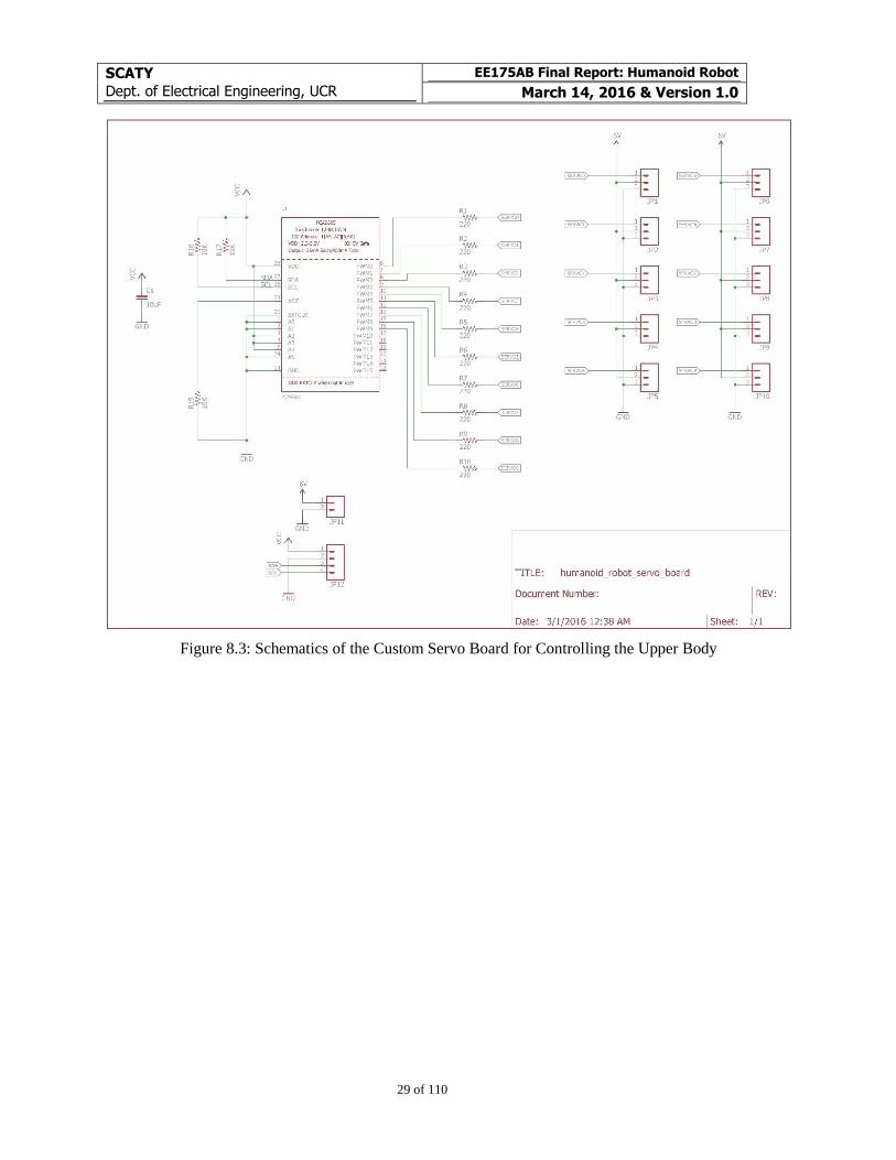
The Servo Board required the custom design of a PCB to use the PCA9685 PWM I2C LED controller to
generate the PPM signals to control the several servo motors used on the upper body and to minimize the
wire management required to provide power to such motors (see Figure 8.3).
SCATY
Dept. of Electrical Engineering, UCR
EE175AB Final Report: Humanoid Robot
March 14, 2016 & Version 1.0
29 of 110
Figure 8.3: Schematics of the Custom Servo Board for Controlling the Upper Body
SCATY
Dept. of Electrical Engineering, UCR
EE175AB Final Report: Humanoid Robot
March 14, 2016 & Version 1.0
30 of 110
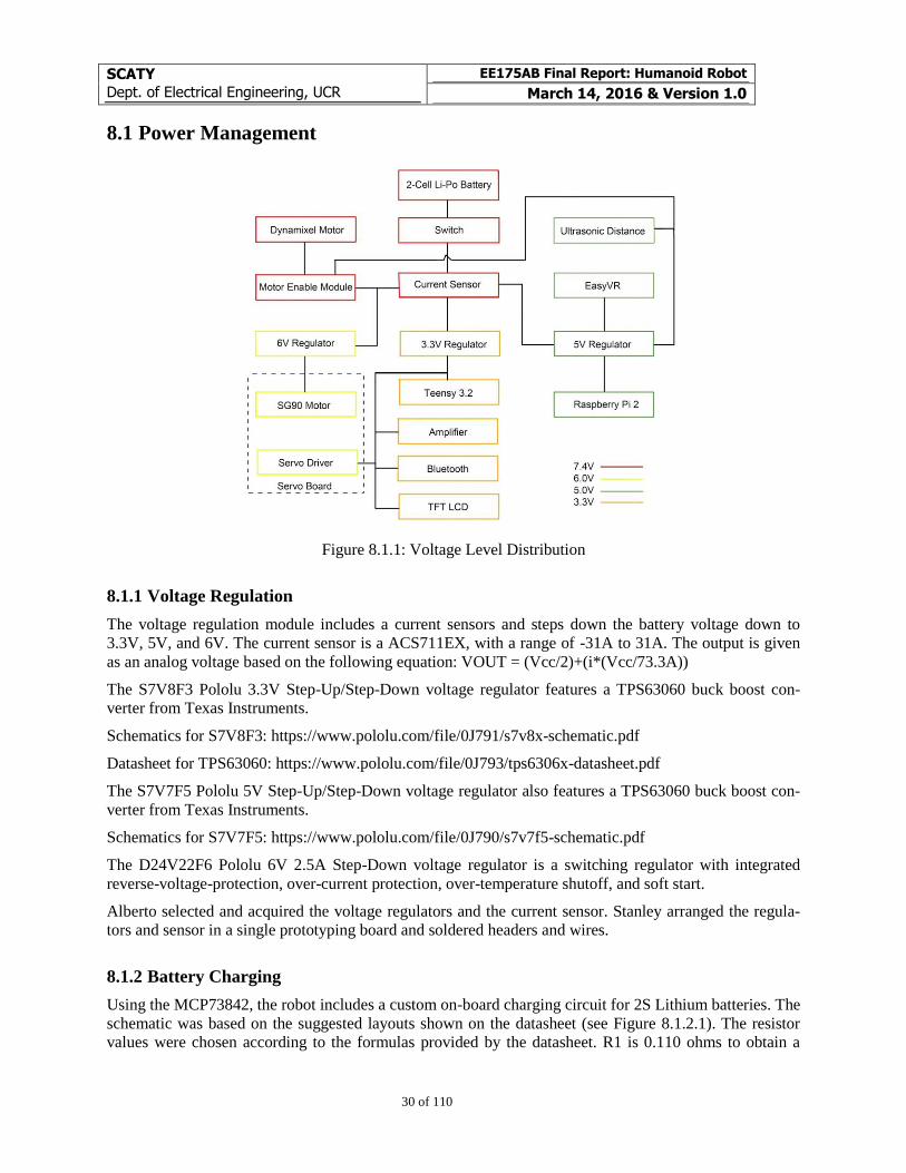
8.1 Power Management
Figure 8.1.1: Voltage Level Distribution
8.1.1 Voltage Regulation
The voltage regulation module includes a current sensors and steps down the battery voltage down to
3.3V, 5V, and 6V. The current sensor is a ACS711EX, with a range of -31A to 31A. The output is given
as an analog voltage based on the following equation: VOUT = (Vcc/2)+(i*(Vcc/73.3A))
The S7V8F3 Pololu 3.3V Step-Up/Step-Down voltage regulator features a TPS63060 buck boost con-
verter from Texas Instruments.
Schematics for S7V8F3: https://www.pololu.com/file/0J791/s7v8x-schematic.pdf
Datasheet for TPS63060: https://www.pololu.com/file/0J793/tps6306x-datasheet.pdf
The S7V7F5 Pololu 5V Step-Up/Step-Down voltage regulator also features a TPS63060 buck boost con-
verter from Texas Instruments.
Schematics for S7V7F5: https://www.pololu.com/file/0J790/s7v7f5-schematic.pdf
The D24V22F6 Pololu 6V 2.5A Step-Down voltage regulator is a switching regulator with integrated
reverse-voltage-protection, over-current protection, over-temperature shutoff, and soft start.
Alberto selected and acquired the voltage regulators and the current sensor. Stanley arranged the regula-
tors and sensor in a single prototyping board and soldered headers and wires.
8.1.2 Battery Charging
Using the MCP73842, the robot includes a custom on-board charging circuit for 2S Lithium batteries. The
schematic was based on the suggested layouts shown on the datasheet (see Figure 8.1.2.1). The resistor
values were chosen according to the formulas provided by the datasheet. R1 is 0.110 ohms to obtain a
SCATY
Dept. of Electrical Engineering, UCR
EE175AB Final Report: Humanoid Robot
March 14, 2016 & Version 1.0
31 of 110
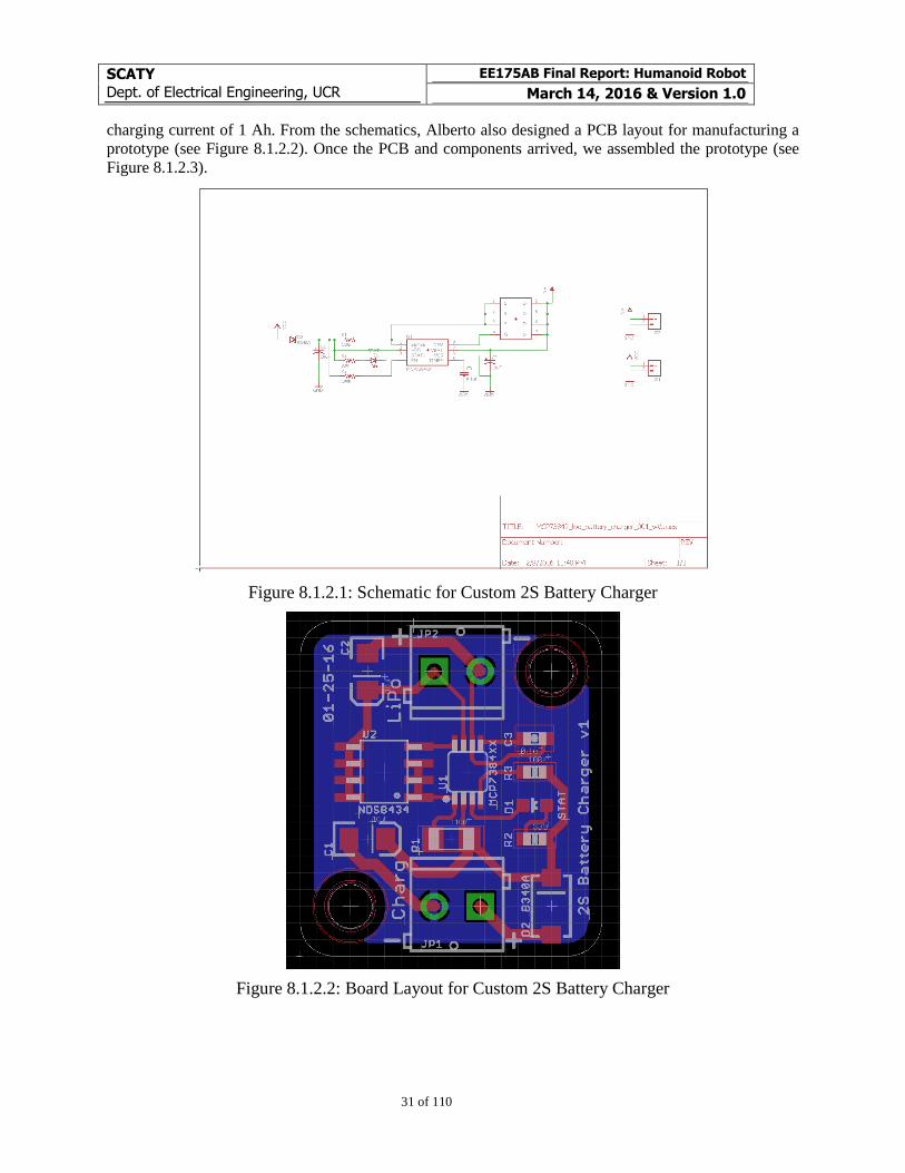
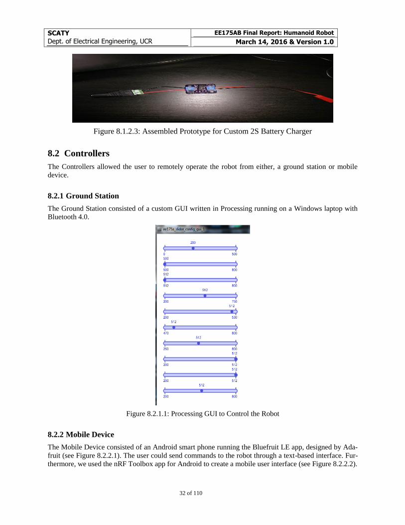
charging current of 1 Ah. From the schematics, Alberto also designed a PCB layout for manufacturing a
prototype (see Figure 8.1.2.2). Once the PCB and components arrived, we assembled the prototype (see
Figure 8.1.2.3).
Figure 8.1.2.1: Schematic for Custom 2S Battery Charger
Figure 8.1.2.2: Board Layout for Custom 2S Battery Charger
SCATY
Dept. of Electrical Engineering, UCR
EE175AB Final Report: Humanoid Robot
March 14, 2016 & Version 1.0
32 of 110
Figure 8.1.2.3: Assembled Prototype for Custom 2S Battery Charger
8.2 Controllers
The Controllers allowed the user to remotely operate the robot from either, a ground station or mobile
device.
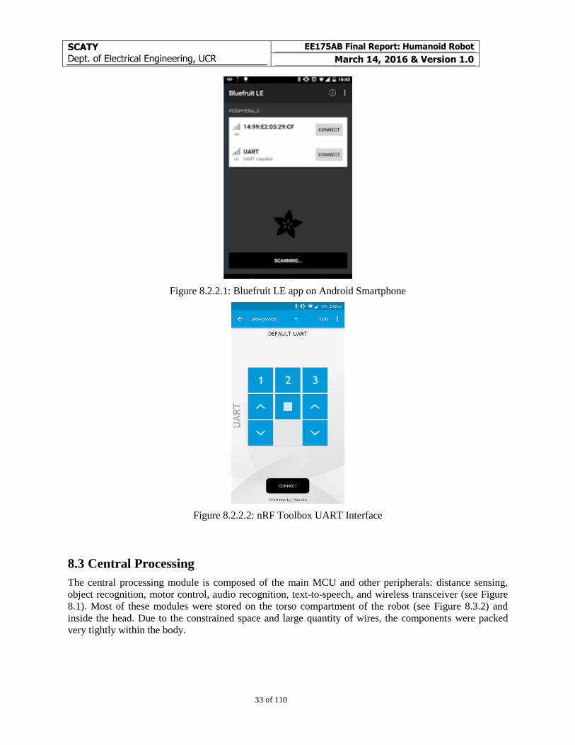
8.2.1 Ground Station
The Ground Station consisted of a custom GUI written in Processing running on a Windows laptop with
Bluetooth 4.0.
Figure 8.2.1.1: Processing GUI to Control the Robot
8.2.2 Mobile Device
The Mobile Device consisted of an Android smart phone running the Bluefruit LE app, designed by Ada-
fruit (see Figure 8.2.2.1). The user could send commands to the robot through a text-based interface. Fur-
thermore, we used the nRF Toolbox app for Android to create a mobile user interface (see Figure 8.2.2.2).
SCATY
Dept. of Electrical Engineering, UCR
EE175AB Final Report: Humanoid Robot
March 14, 2016 & Version 1.0
33 of 110
Figure 8.2.2.1: Bluefruit LE app on Android Smartphone
Figure 8.2.2.2: nRF Toolbox UART Interface
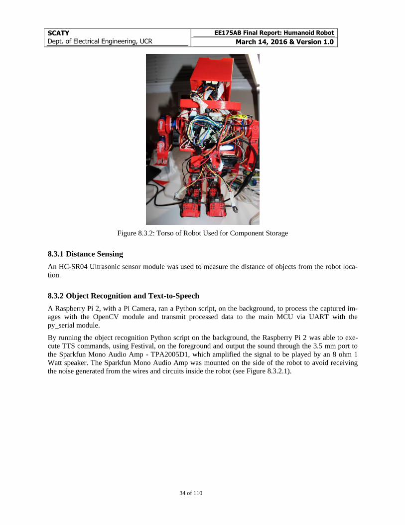
8.3 Central Processing
The central processing module is composed of the main MCU and other peripherals: distance sensing,
object recognition, motor control, audio recognition, text-to-speech, and wireless transceiver (see Figure
8.1). Most of these modules were stored on the torso compartment of the robot (see Figure 8.3.2) and
inside the head. Due to the constrained space and large quantity of wires, the components were packed
very tightly within the body.
SCATY
Dept. of Electrical Engineering, UCR
EE175AB Final Report: Humanoid Robot
March 14, 2016 & Version 1.0
34 of 110
Figure 8.3.2: Torso of Robot Used for Component Storage
8.3.1 Distance Sensing
An HC-SR04 Ultrasonic sensor module was used to measure the distance of objects from the robot loca-
tion.
8.3.2 Object Recognition and Text-to-Speech
A Raspberry Pi 2, with a Pi Camera, ran a Python script, on the background, to process the captured im-
ages with the OpenCV module and transmit processed data to the main MCU via UART with the
py_serial module.
By running the object recognition Python script on the background, the Raspberry Pi 2 was able to exe-
cute TTS commands, using Festival, on the foreground and output the sound through the 3.5 mm port to
the Sparkfun Mono Audio Amp - TPA2005D1, which amplified the signal to be played by an 8 ohm 1
Watt speaker. The Sparkfun Mono Audio Amp was mounted on the side of the robot to avoid receiving
the noise generated from the wires and circuits inside the robot (see Figure 8.3.2.1).
SCATY
Dept. of Electrical Engineering, UCR
EE175AB Final Report: Humanoid Robot
March 14, 2016 & Version 1.0
35 of 110
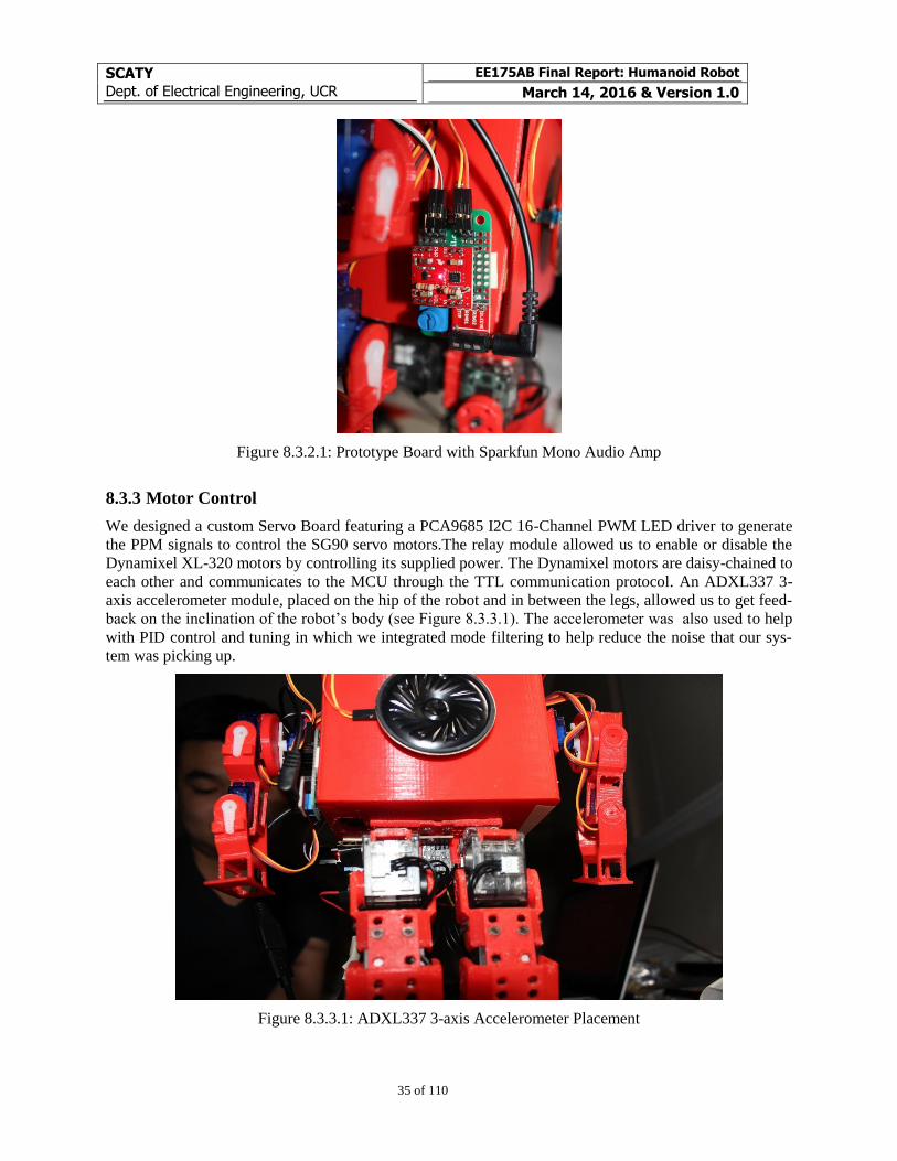
Figure 8.3.2.1: Prototype Board with Sparkfun Mono Audio Amp
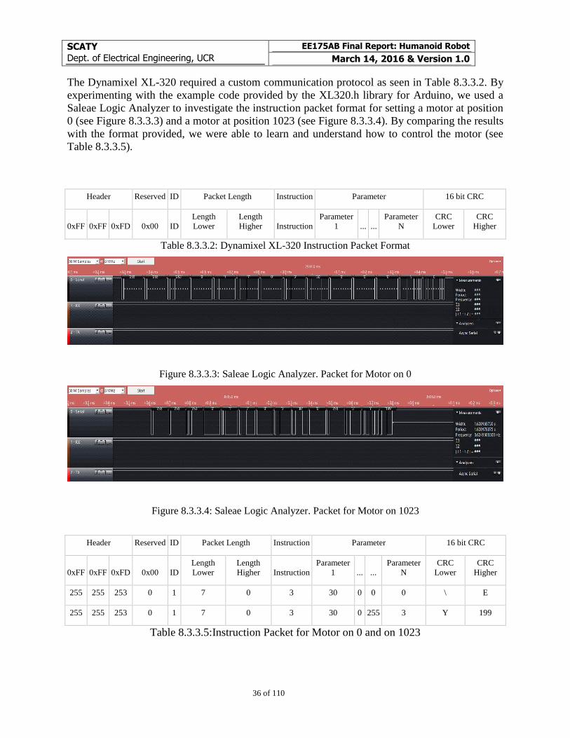
8.3.3 Motor Control
We designed a custom Servo Board featuring a PCA9685 I2C 16-Channel PWM LED driver to generate
the PPM signals to control the SG90 servo motors.The relay module allowed us to enable or disable the
Dynamixel XL-320 motors by controlling its supplied power. The Dynamixel motors are daisy-chained to
each other and communicates to the MCU through the TTL communication protocol. An ADXL337 3-
axis accelerometer module, placed on the hip of the robot and in between the legs, allowed us to get feed-
back on the inclination of the robot’s body (see Figure 8.3.3.1). The accelerometer was also used to help
with PID control and tuning in which we integrated mode filtering to help reduce the noise that our sys-
tem was picking up.
Figure 8.3.3.1: ADXL337 3-axis Accelerometer Placement
SCATY
Dept. of Electrical Engineering, UCR
EE175AB Final Report: Humanoid Robot
March 14, 2016 & Version 1.0
36 of 110
The Dynamixel XL-320 required a custom communication protocol as seen in Table 8.3.3.2. By
experimenting with the example code provided by the XL320.h library for Arduino, we used a
Saleae Logic Analyzer to investigate the instruction packet format for setting a motor at position
0 (see Figure 8.3.3.3) and a motor at position 1023 (see Figure 8.3.3.4). By comparing the results
with the format provided, we were able to learn and understand how to control the motor (see
Table 8.3.3.5).
Header Reserved ID Packet Length Instruction Parameter 16 bit CRC
0xFF 0xFF 0xFD 0x00 ID Length
Lower Length
Higher Instruction Parameter
1 ... ... Parameter
N CRC
Lower CRC
Higher
Table 8.3.3.2: Dynamixel XL-320 Instruction Packet Format
Figure 8.3.3.3: Saleae Logic Analyzer. Packet for Motor on 0
Figure 8.3.3.4: Saleae Logic Analyzer. Packet for Motor on 1023
Header Reserved ID Packet Length Instruction Parameter 16 bit CRC
0xFF 0xFF 0xFD 0x00 ID Length
Lower Length
Higher Instruction Parameter
1 ... ... Parameter
N CRC
Lower CRC
Higher
255 255 253 0 1 7 0 3 30 0 0 0 \ E
255 255 253 0 1 7 0 3 30 0 255 3 Y 199
Table 8.3.3.5:Instruction Packet for Motor on 0 and on 1023
SCATY
Dept. of Electrical Engineering, UCR
EE175AB Final Report: Humanoid Robot
March 14, 2016 & Version 1.0
37 of 110
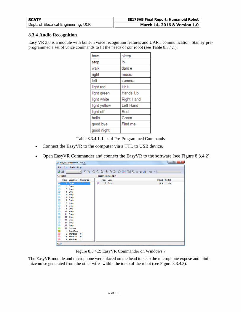
8.3.4 Audio Recognition
Easy VR 3.0 is a module with built-in voice recognition features and UART communication. Stanley pre-
programmed a set of voice commands to fit the needs of our robot (see Table 8.3.4.1).
Table 8.3.4.1: List of Pre-Programmed Commands
Connect the EasyVR to the computer via a TTL to USB device.
Open EasyVR Commander and connect the EasyVR to the software (see Figure 8.3.4.2)
Figure 8.3.4.2: EasyVR Commander on Windows 7
The EasyVR module and microphone were placed on the head to keep the microphone expose and mini-
mize noise generated from the other wires within the torso of the robot (see Figure 8.3.4.3).
SCATY
Dept. of Electrical Engineering, UCR
EE175AB Final Report: Humanoid Robot
March 14, 2016 & Version 1.0
38 of 110
Figure 8.3.4.3: EasyVR Inside the Head, on the bottom side of the photo
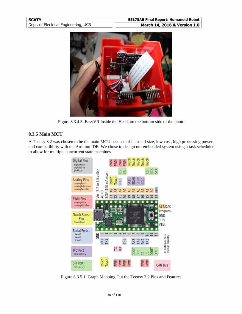
8.3.5 Main MCU
A Teensy 3.2 was chosen to be the main MCU because of its small size, low cost, high processing power,
and compatibility with the Arduino IDE. We chose to design our embedded system using a task scheduler
to allow for multiple concurrent state machines.
Figure 8.3.5.1: Graph Mapping Out the Teensy 3.2 Pins and Features
SCATY
Dept. of Electrical Engineering, UCR
EE175AB Final Report: Humanoid Robot
March 14, 2016 & Version 1.0
39 of 110
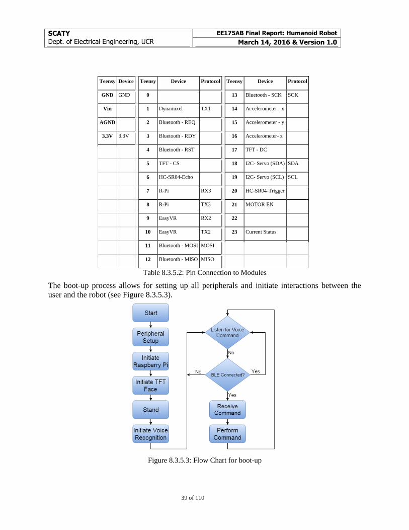
Teensy Device
Teensy Device Protocol
Teensy Device Protocol
GND GND
0
13 Bluetooth - SCK SCK
Vin
1 Dynamixel TX1
14 Accelerometer - x
AGND
2 Bluetooth - REQ
15 Accelerometer - y
3.3V 3.3V
3 Bluetooth - RDY
16 Accelerometer- z
4 Bluetooth - RST
17 TFT - DC
5 TFT - CS
18 I2C- Servo (SDA) SDA
6 HC-SR04-Echo
19 I2C- Servo (SCL) SCL
7 R-Pi RX3
20 HC-SR04-Trigger
8 R-Pi TX3
21 MOTOR EN
9 EasyVR RX2
22
10 EasyVR TX2
23 Current Status
11 Bluetooth - MOSI MOSI
12 Bluetooth - MISO MISO
Table 8.3.5.2: Pin Connection to Modules
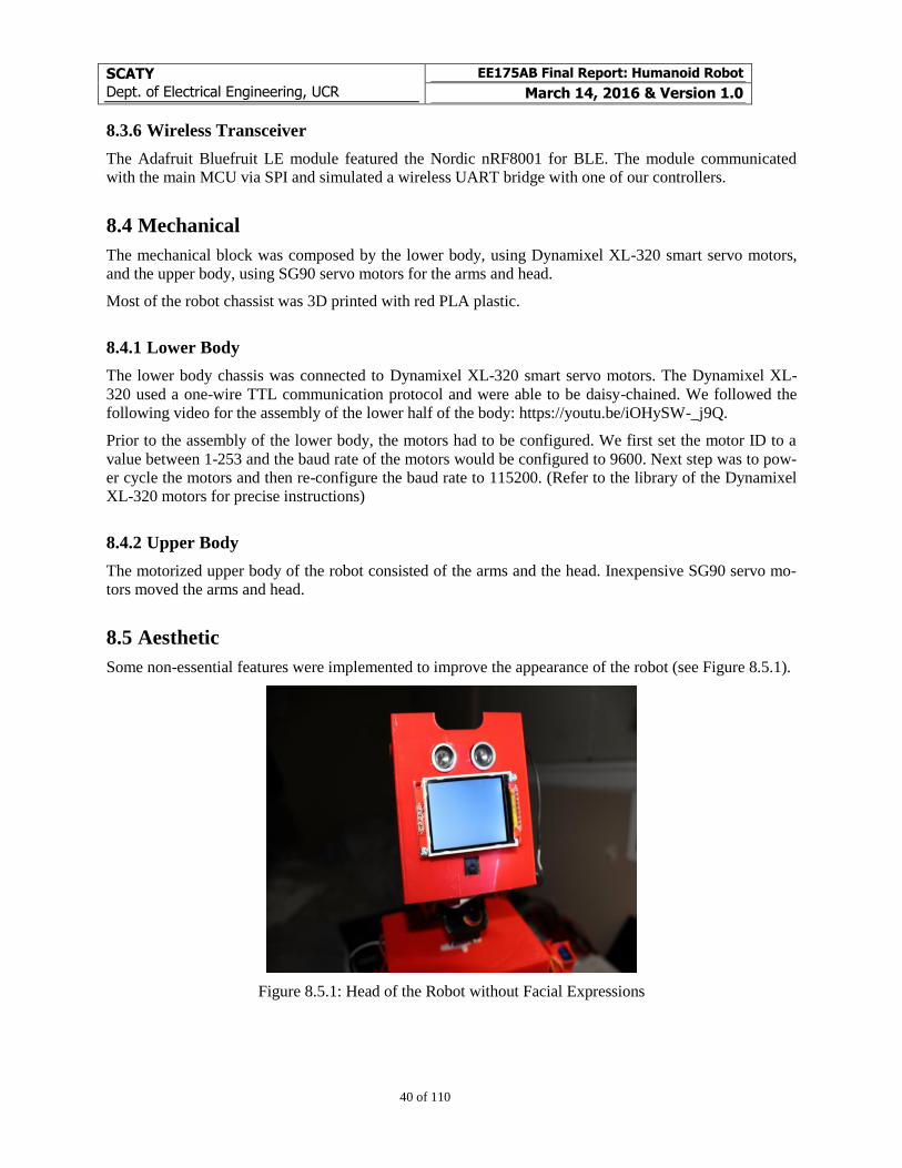
The boot-up process allows for setting up all peripherals and initiate interactions between the
user and the robot (see Figure 8.3.5.3).
Figure 8.3.5.3: Flow Chart for boot-up
SCATY
Dept. of Electrical Engineering, UCR
EE175AB Final Report: Humanoid Robot
March 14, 2016 & Version 1.0
40 of 110
8.3.6 Wireless Transceiver
The Adafruit Bluefruit LE module featured the Nordic nRF8001 for BLE. The module communicated
with the main MCU via SPI and simulated a wireless UART bridge with one of our controllers.
8.4 Mechanical
The mechanical block was composed by the lower body, using Dynamixel XL-320 smart servo motors,
and the upper body, using SG90 servo motors for the arms and head.
Most of the robot chassist was 3D printed with red PLA plastic.
8.4.1 Lower Body
The lower body chassis was connected to Dynamixel XL-320 smart servo motors. The Dynamixel XL-
320 used a one-wire TTL communication protocol and were able to be daisy-chained. We followed the
following video for the assembly of the lower half of the body: https://youtu.be/iOHySW-_j9Q.
Prior to the assembly of the lower body, the motors had to be configured. We first set the motor ID to a
value between 1-253 and the baud rate of the motors would be configured to 9600. Next step was to pow-
er cycle the motors and then re-configure the baud rate to 115200. (Refer to the library of the Dynamixel
XL-320 motors for precise instructions)
8.4.2 Upper Body
The motorized upper body of the robot consisted of the arms and the head. Inexpensive SG90 servo mo-
tors moved the arms and head.
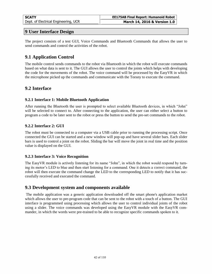
8.5 Aesthetic
Some non-essential features were implemented to improve the appearance of the robot (see Figure 8.5.1).
Figure 8.5.1: Head of the Robot without Facial Expressions

SCATY
Dept. of Electrical Engineering, UCR
EE175AB Final Report: Humanoid Robot
March 14, 2016 & Version 1.0
41 of 110
8.5.1 Face
A 2.2” TFT color display represented the face of the robot, being able to output emotions and other data
with facial expressions.
SCATY
Dept. of Electrical Engineering, UCR
EE175AB Final Report: Humanoid Robot
March 14, 2016 & Version 1.0
42 of 110
9 User Interface Design
The project consists of a test GUI, Voice Commands and Bluetooth Commands that allows the user to
send commands and control the activities of the robot.
9.1 Application Control
The mobile control sends commands to the robot via Bluetooth in which the robot will execute commands
based on what data is sent to it. The GUI allows the user to control the joints which helps with developing
the code for the movements of the robot. The voice command will be processed by the EasyVR in which
the microphone picked up the commands and communicate with the Teesny to execute the command.
9.2 Interface
9.2.1 Interface 1: Mobile Bluetooth Application
After running the Bluetooth the user is prompted to select available Bluetooth devices, in which “John”
will be selected to connect to. After connecting to the application, the user can either select a button to
program a code to be later sent to the robot or press the button to send the pre-set commands to the robot.
9.2.2 Interface 2: GUI
The robot must be connected to a computer via a USB cable prior to running the processing script. Once
connected the GUI can be started and a new window will pop-up and have several slider bars. Each slider
bars is used to control a joint on the robot. Sliding the bar will move the joint in real time and the position
value is displayed on the GUI.
9.2.3 Interface 3: Voice Recognition
The EasyVR module is actively listening for its name “John”, in which the robot would respond by turn-
ing its motor’s LED to blue and then start listening for a command. One it detects a correct command, the
robot will then execute the command change the LED to the corresponding LED to notify that it has suc-
cessfully received and executed the command.
9.3 Development system and components available
The mobile application was a generic application downloaded off the smart phone's application market
which allows the user to pre-program code that can be sent to the robot with a touch of a button. The GUI
interface is programmed using processing which allows the user to control individual joints of the robot
using a slider. The voice commands was developed using the EasyVR module with the EasyVR com-
mander, in which the words were pre-trained to be able to recognize specific commands spoken to it.
SCATY
Dept. of Electrical Engineering, UCR
EE175AB Final Report: Humanoid Robot
March 14, 2016 & Version 1.0
43 of 110
10 Experiment Design and Test Plan
10.1 Design of Experiments
10.1.1 Standing on its own
1. The objective of the experiment is to test whether the robot can stand upright on its own with no
external help. It tested the Dynamixel XL-320 motors and the design of the frame. This measure
the motor’s torque and its ability to withstand the weight of the robot.
2. To set up the experiment, we programmed the Teensy to send an initial position to all motors and
checked to see if the robot was able to stand on its own.
3. The procedure was to turn on the robot and lay it on its feet and see if it stood on its own.
4. The expected result of this experiment was having the robot stand on its own after the initial
power up.
Stanley and Alberto worked on the experiment
10.1.2 Experiment 2: Walking
1. The object of the experiment was validating the robot’s capability to walk. It tested the design
constraints of the robot’s weight and whether the motors could handle it. This measured the mo-
tor’s torque and its ability to withstand the weight of the robot.
2. The setup was to pre-program the walking movement to the robot
3. The procedure was to start the robot and send a command. If the robot walked successfully, the
experiment will have passed.
4. The expected result of the experiment was allowing the robot to walk successfully without falling
down.
Stanley and Alberto worked on the experiment
10.1.3 Experiment 3: Robot Movements
1. The purpose of the experiment was to test the degrees of freedom of the robot. It tested both the
Dynamixel XL-320 and SG90 motors and their ability to move the robot’s frame. This measured
the degrees of freedom of the robot in which there were ten for the lower body, six for the arms,
and two for the head.
2. The setup was to move each motors individually to test the degree of freedom of the robot.
3. The procedure of this experiment was to demonstrate each degree of freedom by holding the ro-
bot and moving each individual joint. If they all moved, then the experiment passed.
4. The expected result of the experiment allowed the robot to demonstrate all degree of freedom by
moving each individual joints
Stanley and Alberto worked on the experiment
SCATY
Dept. of Electrical Engineering, UCR
EE175AB Final Report: Humanoid Robot
March 14, 2016 & Version 1.0
44 of 110
10.1.4 Experiment 4: Manual Control via Bluetooth
1. The objective of the experiment was to test the manual control of the robot via Bluetooth. It tested
the wireless communication from both the ground control and a smart device to the robot.
2. The set up was to connect a smart device or the ground station to the Bluetooth module and send
a command to it.
3. The procedure of this experiment was to connect the robot to the ground station and a smart de-
vice and send commands to the robot. If the robot received the commands, the experiment is suc-
cessful.
4. The expected result of the experiment allowed communication from a ground station and/or a
smart device to the robot through Bluetooth.
Stanley and Alberto worked on the experiment
10.1.5 Experiment 5: Visual Object Recognition
1. The objective of this experiment was to test the ability to recognize objects. It tested the Raspber-
ry Pi camera, the Python script, and the robot’s ability to recognize specific colors with no-
predefined backgrounds.
2. The setup was to let the Raspberry Pi camera scan objects in front of the robot.
3. The procedure of this experiment was to place colored object in front of the robot to let it scan it.
When it detects the object’s color, the motor’s LED will change to the detected color.
4. The expected result of the experiment would be that the robot can detect specific colored objects.
Alberto worked on the experiment
10.1.6 Experiment 6: Object Avoidance
1. The objective of this experiment was to test the ability to avoid objects. It tested the HC-SR04,
our algorithm, and the robot’s ability to detect the distance of any object in front of it between 4
cm to 100 cm.
2. The setup was to place an obstruction in front of the robot and see if the robot would maneuver
around it.
3. The procedure of this experiment was to let the robot walk and have an obstruction in front of it.
If the robot stopped and moved out of the way, the experiment passed.
4. The expected result of the experiment would be that the robot can maneuver around any objects
that is detected by the HC-SR04
Stanley worked on the experiment
10.1.7 Experiment 7: Text-to-Speech
1. The objective of this experiment was to test the ability of the robot to speak base on certain given
text. It tested the speakers of the robot, the Festival TTS software installation, the Bluetooth
communication between a controller and the main MCU, and the wired UART communication
between the Raspberry Pi 2 and the main MCU.
SCATY
Dept. of Electrical Engineering, UCR
EE175AB Final Report: Humanoid Robot
March 14, 2016 & Version 1.0
45 of 110
2. The setup was to have the robot connected to either the ground station or smart device and re-
ceive messages from it.
3. The procedure was to have the Bluetooth receive messages from a smart device or ground station
and then the robot will say the received message. If it correctly said the message, the experiment
passed.
4. The expected result of the experiment would be that the robot can receive text and speak the
phrase it received.
Alberto worked on the experiment
10.1.8 Experiment 8: Voice Commands
1. The objective of this experiment was to test the ability to recognize voice commands. It tested the
EasyVR module and how it recognizes which command it is spoken.
2. The setup was to have the EasyVR initiated and listening to incoming commands in a quiet room.
3. The procedure was to say the command to the microphone and if the robot does the command
stated, the experiment passed.
4. The expected result of the experiment would be that the robot successfully recognizes voice
commands and executes the actions.
Stanley worked on the experiment
10.1.9 Experiment 9: Face Detection
1. The objective of this experiment was to test the ability to detect faces. It tested the Raspberry Pi
camera, the Python script, and the robot’s capability to detect faces.
2. The setup was to have the Raspberry Pi camera scan for faces and to place a face in front of the
camera.
3. The procedure was to place a face in the field of vision of the Raspberry Pi camera. If the camera
detected a face, the expression on the TFT will change to “happy” and the experiment will pass.
4. The expected result of the experiment would be that the robot successfully detects faces.
Alberto worked on the experiment
10.1.10 Experiment 10: Sleep
1. The objective of this experiment was to test the ability of the robot to go to sleep mode. It tested
the capability of the relay to shut off the power to the Dynamixel XL-320 Motors and reduce the
power consumption of the robot.
2. The setup of this experiment was to test the relay that is connected to the motors
3. The procedure was to say or send “sleep” to robot and the robot will go to a resting position and
the relay will shut off the motors. If the motors are off and the current reading is lower, the exper-
iment is successful.
4. The expected result would be that the robot successfully shuts down its motors to conserve power
and that the current reading shows lower power consumption.
Stanley and Alberto worked on the experiment
SCATY
Dept. of Electrical Engineering, UCR
EE175AB Final Report: Humanoid Robot
March 14, 2016 & Version 1.0
46 of 110
10.2 Bug Tracking
Logs from Lab Notebook for 02/23/16:
Saturday (02/20/16)
System’s Test
Fails:
BLE: SPI issues
Servo Board
EASY VR
Sunday (02/21/16)
Servo Board works, but the 6V voltage regulator is only rated to up to 2.5 A. Each servo motor stall cur-
rent is around 0.6A, so it can only handle 4 motors = 2.4 A
Solution: Only connect shoulder (2) and head (2) servo motors
Monday (02/22/16)
BLE SPI issue solved after initiating the TFT SPI pins.
EASY VR. After attempting to troubleshoot it separately, once we connected it back to the system, it
worked normally.
Issues
Dynamixel XL-320 motors. Loss of communication after a few commands were sent.
Analyzed power, cables, and signals.
Diagnosis: The MOSFET Enable setup is not providing enough current. Results of extended study:
1K resistor, yields less than 0.36 A
180 resistor, yields less than 0.6 A
82 resistor, yields less than 0.7 A
10 resistor, yields less than 0.72 A
Suggested solution: Using a relay
10.3 Quality Control
We only experienced issues with the EasyVR after full system implementation:.
Log of Failures of EasyVR on 02/26/16::
EasyVR stops functioning after 15 seconds
SCATY
Dept. of Electrical Engineering, UCR
EE175AB Final Report: Humanoid Robot
March 14, 2016 & Version 1.0
47 of 110
EasyVR stops functioning after 20 seconds
EasyVR stops functioning after 12 seconds
EasyVR stops functioning after 18 seconds
EasyVR stops functioning after 43 seconds
Diagnosis: Exited state machine on unexpected state
Solution 02/28/16: Increase period for state machine accounting for Worst Case Execution time
10.4 Performance bounds
Initializing the Raspberry Pi 2 requires special timing considerations since it’s an Operating System that
requires loading several drivers and files.
10.5 Identification of critical components
The Raspberry Pi 2 is a critical component because, during testing, if the system is shutdown suddenly, it
can corrupt all the files on the system. Therefore, the Raspberry Pi 2 needs to be properly turned on and
shutdown to avoid any corruption.
10.6 Items Not Tested by the Experiments
10.6.1 Pressure Sensor
The original objective of the pressure sensor was to gather data on the weight distribution of the robot.
The sensor would have been placed on the bottom of the feet to sense the shift in weight when standing
and walking. However due to time constraint and the inability to walk, we never had the chance imple-
ment the sensor.
10.6.2 Battery Balancer
Untested design for a 2S Lithium Battery Cell Balancer using the BQ29209 (see Figure 10.6.2.1 and Fig-
ure 10.6.2.2).
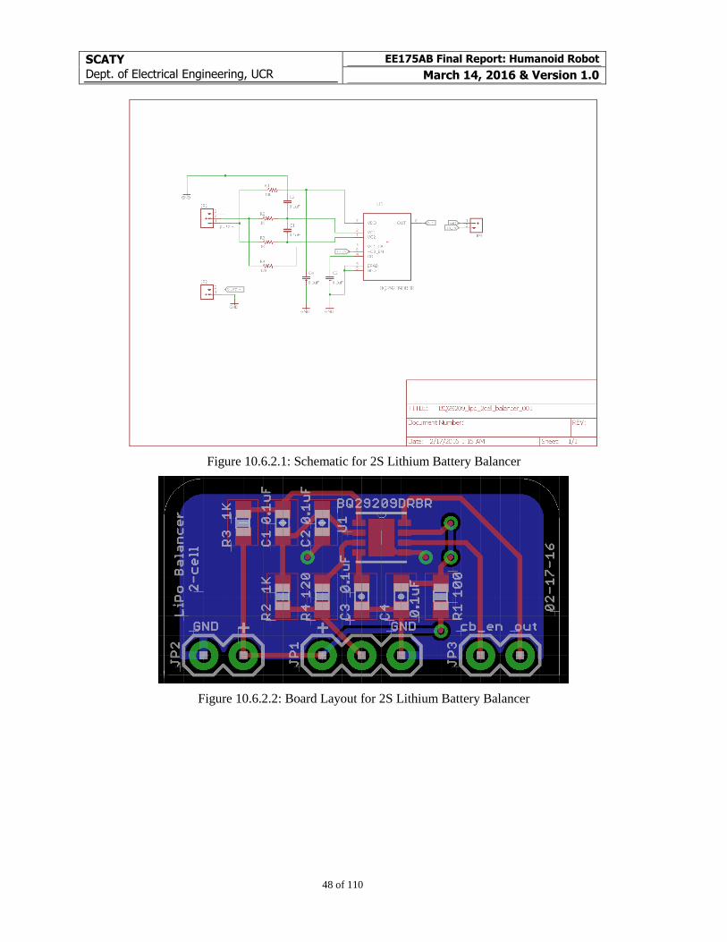
SCATY
Dept. of Electrical Engineering, UCR
EE175AB Final Report: Humanoid Robot
March 14, 2016 & Version 1.0
48 of 110
Figure 10.6.2.1: Schematic for 2S Lithium Battery Balancer
Figure 10.6.2.2: Board Layout for 2S Lithium Battery Balancer
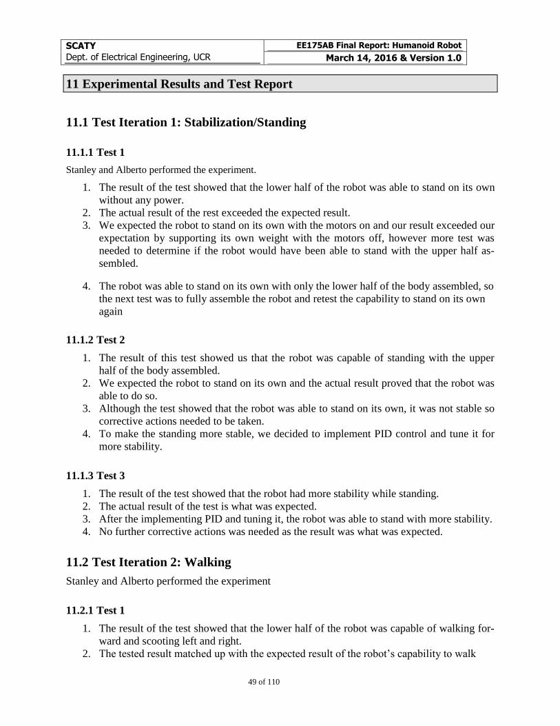
SCATY
Dept. of Electrical Engineering, UCR
EE175AB Final Report: Humanoid Robot
March 14, 2016 & Version 1.0
49 of 110
11 Experimental Results and Test Report
11.1 Test Iteration 1: Stabilization/Standing
11.1.1 Test 1
Stanley and Alberto performed the experiment.
1. The result of the test showed that the lower half of the robot was able to stand on its own
without any power.
2. The actual result of the rest exceeded the expected result.
3. We expected the robot to stand on its own with the motors on and our result exceeded our
expectation by supporting its own weight with the motors off, however more test was
needed to determine if the robot would have been able to stand with the upper half as-
sembled.
4. The robot was able to stand on its own with only the lower half of the body assembled, so
the next test was to fully assemble the robot and retest the capability to stand on its own
again
11.1.2 Test 2
1. The result of this test showed us that the robot was capable of standing with the upper
half of the body assembled.
2. We expected the robot to stand on its own and the actual result proved that the robot was
able to do so.
3. Although the test showed that the robot was able to stand on its own, it was not stable so
corrective actions needed to be taken.
4. To make the standing more stable, we decided to implement PID control and tune it for
more stability.
11.1.3 Test 3
1. The result of the test showed that the robot had more stability while standing.
2. The actual result of the test is what was expected.
3. After the implementing PID and tuning it, the robot was able to stand with more stability.
4. No further corrective actions was needed as the result was what was expected.
11.2 Test Iteration 2: Walking
Stanley and Alberto performed the experiment
11.2.1 Test 1
1. The result of the test showed that the lower half of the robot was capable of walking for-
ward and scooting left and right.
2. The tested result matched up with the expected result of the robot’s capability to walk
SCATY
Dept. of Electrical Engineering, UCR
EE175AB Final Report: Humanoid Robot
March 14, 2016 & Version 1.0
50 of 110
3. The robot was able to walk, however this was only with the lower half. We need to as-
semble the top half of the robot and retest.
4. As stated in the result analysis, the robot’s walking needed to be retested with the assem-
bly of the upper half of the body.
11.2.2 Test 2
1. The result of the fully assembled robot’s walking was a failure.
2. The tested result did not match with the expected result as the robot was unable to walk.
3. We believe that the robot was unable to walk because of the uneven weight distribution
where the top half was significant heavier than the lower half.
4. For a corrective action, PID control and tuning was implemented.
11.2.3 Test 3
1. The result of the test showed that the robot was still unable to walk even with the imple-
mentation of PID.
2. The tested result did not match with the expected result as the robot was unable to walk.
3. We believed the robot was unable to walk because of the big margin of error the plastic
frame had. The plastic was capable of moving a couple millimeter while the motors were
not moving, which threw off the entire balance of the entire system.
4. A corrective actions that we considered was to redesign the entire system in which we
would first create a dynamic model of the robot.
11.3 Test Iteration 3: Robot Movements
Stanley and Alberto performed the experiment
11.3.1 Test 1
1. The result of the test showed the robot capability of moving the head, arms, and legs, and
show the 18 degrees of freedom.
2. The actual result showed that the robot was capable of moving each joints, but only two
joints on the arms were capable to move simultaneously.
3. We were able to determine that the joints on the arm was only capable of moving only
two out of the six joints, so corrective actions needed to be taken.
4. Given the result, we plan to add an additional 6v regulator to see if this would rectify our
problem.
11.4 Test Iteration 4: Manuel Control via Bluetooth
Stanley and Alberto performed the experiment
11.4.1 Test 1
1. The result of the result showed the robot capability to communicate with a smart device, in
which the Bluetooth module was able to communicate to the Teensy through SPI communication.
SCATY
Dept. of Electrical Engineering, UCR
EE175AB Final Report: Humanoid Robot
March 14, 2016 & Version 1.0
51 of 110
2. The actual result showed the robot’s ability to receive data from a smart device through Bluetooth
which matched with our expected result.
3. We were able to communicate to the robot within a ten feet radius and send commands to it with
little to no delay.
4. Given the result, no corrective actions were needed to be taken.
11.5 Test Iteration 5: Visual Object Recognition
11.5.1 Test 1
Stanley and Alberto performed the experiment
1. The result of the test was that the robot was capable of detecting green and red objects and
changed eyes colors based on which color was detected.
2. Our tested result of detecting colored object was as described in our expected result.
3. The robot was able to detect the green and red makers we placed in front of it and changed its
eyes based on the color, however, the robot will change its eye color on any detection of green
and red in the background.
4. The robot was capable of detecting the colored objects of our choice so no corrective actions was
needed.
11.6 Test Iteration 6: Text-to-Speech
Alberto performed the experiment
11.6.1 Test 1
1. The result of the test showed that the robot was capable of “speaking” the English test we
sent to it.
2. The tested result matched up with the expected result as the robot was capability of play-
ing the text we sent it through the speaker.
3. The robot voice is a bit soft, however that can be fixed with a stronger speaker, but the
text-to-speech software worked well with no issues.
4. The end result was successful as the robot was able to speak English text we sent it, so no
need to take any corrective actions
11.7 Test Iteration 7: Voice Commands
Stanley performed the experiment
11.7.1 Test 1
1. The test resulted to the EasyVR detecting the voice and run the function corresponding to
the command received. The robot was able to successfully recognize some words, but
had troubles with others.
SCATY
Dept. of Electrical Engineering, UCR
EE175AB Final Report: Humanoid Robot
March 14, 2016 & Version 1.0
52 of 110
2. We expected the robot to recognize the commands spoken to it and it was able to recog-
nize most words with no problem.
3. We noticed that the more complex phrases gave the recognition software some trouble
due to the fact that the EasyVR Commander limits the training to two per word.
4. To further develop the recognition, we decided to change the name from “Scaty” to
“John” for the simplicity and add more words to the database.
11.7.2 Test 2
1. The resulted test showed the EasyVR working and responding to the name “John” and
the new phrases that were added to the data set.
2. The tested result matched well with our expected result.
3. After retraining the robot to “John”, the success rate of the robot’s response was greatly
increased.
4. With the robot capability of recognizing speech, no corrective actions was further neces-
sary.
11.8 Test Iteration 8: Face Detection
Alberto performed the experiment
11.8.1 Test 1
1. The test was to determine if the Raspberry Pi camera, Python script, and the robot’s ca-
pability to detect any faces and if it did, the TFT display would change the robot’s reac-
tion.
2. The tested result matched up with our expected result with the capability of detecting a
face in front of the camera.
3. When a face was in the vicinity of the camera, the robot’s expression on the TFT display
changed.
4. Since the camera software successfully detected faces, no further testing was required.
11.9 Test Iteration 9: Battery Charging
Stanley and Alberto performed the experiment
Data from Lab Notebook:
Initial testing for the 2S Lithium Charger custom board yielded negative results. The custom circuit was not charging the battery,
and there seemed to be some irregularities on voltages on the output side. Hence, I decided to set that part of the project aside
and focused on the other components of the project.
The setup of the test included a 9V 1A wall adapter power supply, a 2.1 mm jack adapter, wires, the 2S Lithium Charger custom
board - assembled, a JST connector, and a 1000 mAH 2S Lithium battery. I used a regular multimeter to measure input and
output voltages.
Assuming all settings were correct, I set the battery to charge for 10 minutes. At the end, I measured the status of the battery and
compared it with its initial status, and I saw no changes.
SCATY
Dept. of Electrical Engineering, UCR
EE175AB Final Report: Humanoid Robot
March 14, 2016 & Version 1.0
53 of 110
Debugging and New Test
I checked the polarity of the 2.1 mm jack adapter, the wire connections, and the 2S Lithium Charger custom board circuitry and
soldered components. They all seemed to be correct. The 9V 1A power supply was supplying specifically 9.25 V, which is within
the input voltage operating range of the MCP73842. To verify that the charger system was supplying current to the battery, I
connected a multimeter in-line to the output of the 2S Lithium Charger and the battery to measure the charging current. When I
plugged in the 9V power supply, the current readings were around 0.09 A and then would spike to around 0.5 A. It seemed like a
very slow PWM, so I double-checked with the datasheet to look for this kind of behavior, but found nothing related to it. Hence, I
assumed it was an irregular behavior. The expected behavior should have been a constant current of 1 A or a slowly decreasing
current, depending on the charging stage.
I assumed that the issue was the power supply because the 9V 1A wall adapter power supply was barely within specifications for
this task. I switched it for a 12V 1.5A wall adapter power supply. Once I changed it and plugged it in, I immediately got a solid
0.81 A reading on the multimeter, meaning that the charger system was indeed charging the battery. I stopped the process and
took some measurements before restarting the test.
Test
Time = 0 min
Vinput = 12.12 V
Voutput = 8.36 V
Battery Status:
Vdd = 7.683 V (47%)
V1s = 3.837 V
V2s = 3.846 V
Vdelta = 0.009 V
Procedure: Connect system
Iout = 0.81 A
Vinput = 12.09 V
Vout = 8.36 V
Time = 5 min
Iout = 0.60 A
Procedure: Unplug system
Battery Status:
Vdd = 7.773 V (58%)
V1s = 3.882 V
V2s = 3.891 V
Vdelta = 0.009 V
SCATY
Dept. of Electrical Engineering, UCR
EE175AB Final Report: Humanoid Robot
March 14, 2016 & Version 1.0
54 of 110
Observations:
The 2S Lithium Charger custom board was very hot. At first, I observed some fumes from the board but further investigation
yielded that it might have been caused by flux residue. By studying the datasheet for the MCP73842, the Thermal Considerations
sections on page 16 explains that the power dissipation = (Vddmax - Vpthmin) x Iregmax. In this test, power dissipation could be
approximated to (12 - 7.7) x (0.8) = 3.44 W. The P-MOSFET NDS8434 component package is rated to dissipate up to 2.5 W,
when the PCB layout aids with heat dissipation. However, the current design of the 2S Lithium Charger custom board should
allow for only up to 1 W of safe heat dissipation.
Time = 7 min = 5 min (charging) + 2 min (rest)
Battery Status:
Vdd = 7.751 V (56%)
V1s = 3.869 V
V2s = 3.882 V
Vdelta = 0.013 V
Observations:
The 2S Lithium Charger system was set to charge the battery at 1 Ah, so it would take 1 hour to fully charge the 1000 mAh 2S
Lithium battery used in this test. After 5 min, the battery was charged 9%, which approximately matches the expected result.
Conclusion
This test successfully shows that the 2S Lithium Charger custom board can charge a 2S Lithium battery in approximately 1-hour;
however, due to thermal considerations, this iteration of the prototype would not provide a safe solution for an on-board charg-
ing system.
SCATY
Dept. of Electrical Engineering, UCR
EE175AB Final Report: Humanoid Robot
March 14, 2016 & Version 1.0
55 of 110
12 Conclusion and Future Work
12.1 Conclusion
The conclusion of our product was satisfying, but there are still several features that can be added
onto the robot. Overall, we met the majority of goals set for verification and validation. Some technical
objectives we had included combining many branches of electrical engineering to create our final project.
We implemented state machines, a task scheduler, power management, computer vision, text-to-speech,
voice recognition, and many communication protocols that allowed many peripherals to work together, as
well as Bluetooth to allow control through a smart device.
Despite completing the majority of our goals, we were unable to get the walking to work. The
robot was very top heavy and did not have a stable center of mass. On top of that, the 3D printed frame
had a flexibility that added instability to the body that caused the frame to behave in an unpredictable
manner. We found a possible solution towards the end of the project, which was to create a dynamic
model for our robot so we would know how heavy each area was and by having the model, it would be
easy to determine the center of mass. Another possible solution to the failure of walking is to have the
frame of the body professionally manufactured. Our frame was printed by the local IEEE chapter with
their Makerbot 3D printer which did not provide a high resolution print. Since we were unable to get
walking to function, we were not able to test the object avoidance algorithm that we had wrote. Once the
walking feature is available, testing and implementing the object avoidance feature would be very easy.
Although we did not have the feature of walking, we had a lot of peripherals and protocols im-
plemented on the robot. Our robot was still capable of moving its joints, recognize voices, colors, and
faces, have an interactive screen that displayed multiple different emotions for the robot, text-to-speech,
and have Bluetooth communication. We were able to speak to the robot to have it execute the commands
or we were able to connect to it via Bluetooth and send commands for it execute them.
The tasks Stanley was responsible for was the assembly of the robot, PID control and tuning,
voice recognition, power management, and Bluetooth. Alberto was responsible for the 3D printing of the
robot, the GUI, nRF Toolbox App, computer vision, text-to-speech, and battery management. Lastly the
both of us were responsible for the upper body control on top of the wire management and overall coding.
Stanley: This project I learned about many different branches of electrical engineering. I was able
to further develop my embedded system knowledge and skill with the implementation of all the different
communication protocols on top of the integration of multiple peripherals. Most of the tasks I was respon-
sible were either taught in theory or not implemented hands on in lab or was not taught in school. This
project taught me the importance of research and the importance of pre-planning everything before exe-
cuting it. For example, I only learned about PID control and tuning through theory in my courses, howev-
er it was my first time implementing on a project. It showed me how big of a difference from learning
about a theory and then actually applying it which led to many complications and trail-and-errors. On top
of learning new things, I also learned when to stop and find an alternative solution. For the goal of creat-
ing a low budget project, I initially tried to use a software library for voice recognition with a small ampli-
fier and microphone however it prove to be really inconsistent. Alberto and I then tried to work together
to get it to function, however with all the inconsistent result we decided to halt the process and look for a
better solution which led to the purchase of the EasyVR module. For professional growth, this project
allowed me a small glimpse as to what I would be doing as a real engineering in the industry. This project
taught me many technical skills and showed me that I knowledge is never ending and that I always have
something new to improve or learn.

SCATY
Dept. of Electrical Engineering, UCR
EE175AB Final Report: Humanoid Robot
March 14, 2016 & Version 1.0
56 of 110
Alberto: During this project, I learned many skills and knowledge from tackling a wide variety of
technical challenges, understood the design and development process, and improved my soft skills while
working on a team. This robot introduced several technical challenges that I hadn’t encountered before.
Interfacing several peripherals together showed me the advantages of concurrent state machine design.
While exploring the possible implementations for the features we wanted on the robot, I came up with
several solutions that seemed very simple or complex in appearance but, in reality, required comparing
several factors, such as price, size, power, quality, technical complexity, development time, and others.
For example, when implementing Text-to-Speech, I came up with several solutions that produced very
low-quality results. Hence, I had to discard these solutions in spite of how much time I spent on them
because they did not meet our project criteria. Even though we wanted good quality, I had to set ourselves
to a medium quality solution with the Raspberry Pi 2 and the Festival TTS solution because better quality
solutions would require much more on price, size, and development time.
I have worked in several projects before starting this one, but this project has been one of the
most well planned projects I have worked in because of the design and development planning we set since
the beginning of the project. Even though we had some challenges on the timeline, we were expecting
them because they are part of the nature of research and development. All the same, setting good specifi-
cations at the beginning of the project allowed us to have a clear goal and improved our ability to plan our
timeline appropriately.
Even though we were only a team of 2 members, I improved my communication skills, documen-
tation writing, meeting planning, and teamwork ability. I managed to work and coordinate working ses-
sions with my partner despite our busy schedules. Since we had limited team working sessions, our doc-
umentation writing and coordination were essential to make sure we completed the project, so I feel we
were able to work together very well due to our great soft skills and teamwork.
12.2 Future Work
For our future work, the first step is to accomplish the goals that we weren’t able to complete. We
believe that in order to accomplish walking, a dynamical model would first need to be created before
physically building the robot. After getting the walking to work, the next step would be implementing the
object avoidance algorithm with the HSR-04 Ultra Sonic Distance senor.
After accomplishing all our goals, the next step would be to redesign the wire management. Cur-
rently our robot has a vast amount of wires running inside it which makes it very hard to disconnect and
connect components. A solution to that would be designing a printed circuit board for the entire system.
This would not only minimize the amount of wires in the robot, but it would lessen the weight of the en-
tire robot which would help with the balance and walking of the robot.
12.3 Acknowledgement
Dr Roman Chomko
o Faculty advisor
Dr. Anastasios Mourikis
o Dynamic Modeling
Joshua Yuen, UCR CS Ph.D. Graduate Candidate
o 1-wire TTL TX/RX Signal Isolation for Dynamixel XL-320 motors
Pavle Kirilov
o PCB Manufacturing
Rex Lu, UCLA ME Master Graduate Candidate
o Walking trajectory for bipedal robots
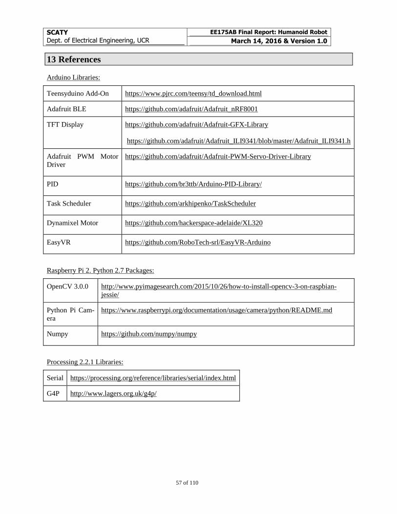
SCATY
Dept. of Electrical Engineering, UCR
EE175AB Final Report: Humanoid Robot
March 14, 2016 & Version 1.0
57 of 110
13 References
Arduino Libraries:
Teensyduino Add-On https://www.pjrc.com/teensy/td_download.html
Adafruit BLE https://github.com/adafruit/Adafruit_nRF8001
TFT Display https://github.com/adafruit/Adafruit-GFX-Library
https://github.com/adafruit/Adafruit_ILI9341/blob/master/Adafruit_ILI9341.h
Adafruit PWM Motor
Driver https://github.com/adafruit/Adafruit-PWM-Servo-Driver-Library
PID https://github.com/br3ttb/Arduino-PID-Library/
Task Scheduler https://github.com/arkhipenko/TaskScheduler
Dynamixel Motor https://github.com/hackerspace-adelaide/XL320
EasyVR https://github.com/RoboTech-srl/EasyVR-Arduino
Raspberry Pi 2. Python 2.7 Packages:
OpenCV 3.0.0 http://www.pyimagesearch.com/2015/10/26/how-to-install-opencv-3-on-raspbian-
jessie/
Python Pi Cam-
era https://www.raspberrypi.org/documentation/usage/camera/python/README.md
Numpy https://github.com/numpy/numpy
Processing 2.2.1 Libraries:
Serial https://processing.org/reference/libraries/serial/index.html
G4P http://www.lagers.org.uk/g4p/
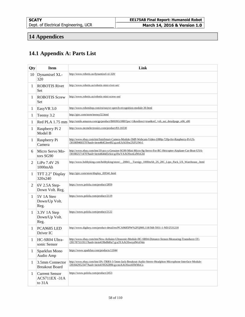
SCATY
Dept. of Electrical Engineering, UCR
EE175AB Final Report: Humanoid Robot
March 14, 2016 & Version 1.0
58 of 110
14 Appendices
14.1 Appendix A: Parts List
Qty Item Link
10 Dynamixel XL-
320
http://www.robotis.us/dynamixel-xl-320/
1 ROBOTIS Rivet
Set
http://www.robotis.us/robotis-mini-rivet-set/
1 ROBOTIS Screw
Set
http://www.robotis.us/robotis-mini-screw-set/
1 EasyVR 3.0 http://www.robotshop.com/en/easyvr-speech-recognition-module-30.html
1 Teensy 3.2 http://pjrc.com/store/teensy32.html
1 Red PLA 1.75 mm http://smile.amazon.com/gp/product/B00J0GO8I0?psc=1&redirect=true&ref_=oh_aui_detailpage_o06_s00
1 Raspberry Pi 2
Model B
http://www.mcmelectronics.com/product/83-16530
1 Raspberry Pi
Camera
http://www.ebay.com/itm/SainSmart-Camera-Module-5MP-Webcam-Video-1080p-720p-for-Raspberry-Pi-US-
/301809460370?hash=item46453ee492:g:znEAAOSw2XFUiWr1
6 Micro Servo Mo-
tors SG90
http://www.ebay.com/itm/10-pcs-x-Genuine-SG90-Mini-Micro-9g-Servo-For-RC-Heicopter-Airplane-Car-Boat-USA-
/301802571470?hash=item4644d5c6ce:g:HwYAAOSwnLdWsGhI
2 LiPo 7.4V 2S
1000mAh
http://www.hobbyking.com/hobbyking/store/__20841__Turnigy_1000mAh_2S_20C_Lipo_Pack_US_Warehouse_.html
1 TFT 2.2" Display
320x240
http://pjrc.com/store/display_ili9341.html
2 6V 2.5A Step-
Down Volt. Reg.
https://www.pololu.com/product/2859
1 5V 1A Steo
Down/Up Volt.
Reg.
https://www.pololu.com/product/2119
1 3.3V 1A Step
Down/Up Volt.
Reg.
https://www.pololu.com/product/2122
1 PCA9685 LED
Driver IC
http://www.digikey.com/product-detail/en/PCA9685PW%2FQ900,118/568-5931-1-ND/2531218
1 HC-SR04 Ultra-
sonic Sensor
http://www.ebay.com/itm/New-Arduino-Ultrasonic-Module-HC-SR04-Distance-Sensor-Measuring-Transducer-5Y-
/281787551911?hash=item419bd8d0a7:g:u3YAAOSwoydWoF4m
1 Sparkfun Mono
Audio Amp
https://www.sparkfun.com/products/11044
1 3.5mm Connector
Breakout Board
http://www.ebay.com/itm/1Pc-TRRS-3-5mm-Jack-Breakout-Audio-Stereo-Headphon-Microphone-Interface-Module-
/281842952347?hash=item419f26289b:g:cnoAAOSwo0JWMxCs
1 Current Sensor
ACS711EX -31A
to 31A
https://www.pololu.com/product/2453
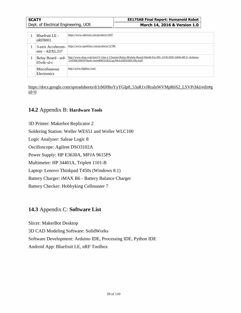
SCATY
Dept. of Electrical Engineering, UCR
EE175AB Final Report: Humanoid Robot
March 14, 2016 & Version 1.0
59 of 110
1 Bluefruit LE -
nRF8001
https://www.adafruit.com/products/1697
1 3-axis Accelerom-
eter - ADXL337
https://www.sparkfun.com/products/12786
1 Relay Board - srd-
05vdc-sl-c
http://www.ebay.com/itm/5V-One-1-Channel-Relay-Module-Board-Shield-For-PIC-AVR-DSP-ARM-MCU-Arduino-
/310566336050?hash=item484f323632:g:iNkAAMXQHU1RyAzD
Miscellaneous
Electronics
http://www.digikey.com/
https://docs.google.com/spreadsheets/d/1tMJ0hoYyYGIp8_53aR1vJRralnWVMpR6S2_LSVPcbkI/edit#g
id=0
14.2 Appendix B: Hardware Tools
3D Printer: Makerbot Replicator 2
Soldering Station: Weller WES51 and Weller WLC100
Logic Analyzer: Saleae Logic 8
Oscilloscope: Agilent DSO3102A
Power Supply: HP E3630A, MPJA 9615PS
Multimeter: HP 34401A, Triplett 1101-B
Laptop: Lenovo Thinkpad T450s (Windows 8.1)
Battery Charger: iMAX B6 - Battery Balance Charger
Battery Checker: Hobbyking Cellmaster 7
14.3 Appendix C: Software List
Slicer: MakerBot Desktop
3D CAD Modeling Software: SolidWorks
Software Development: Arduino IDE, Processing IDE, Python IDE
Android App: Bluefruit LE, nRF Toolbox
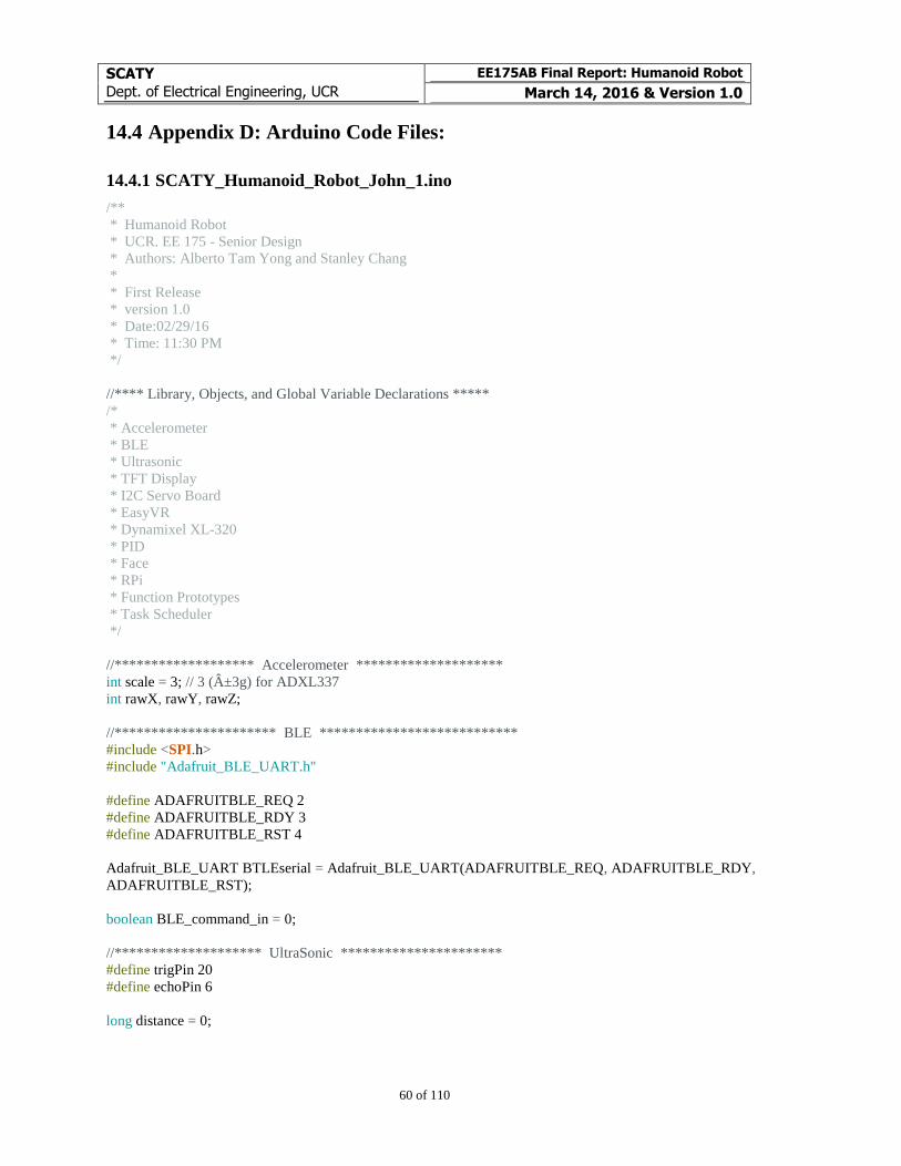
SCATY
Dept. of Electrical Engineering, UCR
EE175AB Final Report: Humanoid Robot
March 14, 2016 & Version 1.0
60 of 110
14.4 Appendix D: Arduino Code Files:
14.4.1 SCATY_Humanoid_Robot_John_1.ino
/**
* Humanoid Robot
* UCR. EE 175 - Senior Design
* Authors: Alberto Tam Yong and Stanley Chang
*
* First Release
* version 1.0
* Date:02/29/16
* Time: 11:30 PM
*/
//**** Library, Objects, and Global Variable Declarations *****
/*
* Accelerometer
* BLE
* Ultrasonic
* TFT Display
* I2C Servo Board
* EasyVR
* Dynamixel XL-320
* PID
* Face
* RPi
* Function Prototypes
* Task Scheduler
*/
//******************* Accelerometer ********************
int scale = 3; // 3 (±3g) for ADXL337
int rawX, rawY, rawZ;
//********************** BLE ***************************
#include <SPI.h>
#include "Adafruit_BLE_UART.h"
#define ADAFRUITBLE_REQ 2
#define ADAFRUITBLE_RDY 3
#define ADAFRUITBLE_RST 4
Adafruit_BLE_UART BTLEserial = Adafruit_BLE_UART(ADAFRUITBLE_REQ, ADAFRUITBLE_RDY,
ADAFRUITBLE_RST);
boolean BLE_command_in = 0;
//******************** UltraSonic **********************
#define trigPin 20
#define echoPin 6
long distance = 0;
SCATY
Dept. of Electrical Engineering, UCR
EE175AB Final Report: Humanoid Robot
March 14, 2016 & Version 1.0
61 of 110
//******************* TFT Display ***********************
#include "Adafruit_GFX.h"
#include "Adafruit_ILI9341.h"
//SPI already included
#define TFT_DC 17
#define TFT_CS 5
Adafruit_ILI9341 tft = Adafruit_ILI9341(TFT_CS, TFT_DC);
//******************* I2C Servo Board ************************
#include <Wire.h>
#include <Adafruit_PWMServoDriver.h>
Adafruit_PWMServoDriver pwm = Adafruit_PWMServoDriver(0x5C); //address set to 0x5C
#define SERVOMIN 150 // this is the 'minimum' pulse length count (out of 4096)
#define SERVOMAX 600 // this is the 'maximum' pulse length count (out of 4096)
char R_Shoulder = 0;
char R_Elbow = 1;
char R_Wrist = 2;
char L_Shoulder = 3;
char L_Elbow = 4;
char L_Wrist = 5;
char Neck_LR = 6;
char Neck_UD = 7;
int init_rest_arms[10]= {50,160,65,131,150,60,65,80};
int curr_arms_pos[10] = {50,160,65,131,150,60,65,80};
int target_arms_pos[10] = {50,160,65,131,150,60,65,80};
int target_arms_time[10] = {0,0,0,0,0,0,0,0,0,0};
boolean servo_sm_update_en = 0;
char motor_joint[10] = {R_Shoulder, R_Elbow, R_Wrist, L_Shoulder, L_Elbow, L_Wrist, Neck_LR, Neck_UD};
//******************** EasyVR ************************
#include "Arduino.h"
#if defined(SERIAL_PORT_USBVIRTUAL)
#define port SERIAL_PORT_HARDWARE
#define pcSerial SERIAL_PORT_USBVIRTUAL
#else
#define pcSerial SERIAL_PORT_MONITOR
#endif
#include "EasyVR.h"
EasyVR easyvr(Serial2);
//Groups and Commands
enum Groups
{
GROUP_0 = 0,
SCATY
Dept. of Electrical Engineering, UCR
EE175AB Final Report: Humanoid Robot
March 14, 2016 & Version 1.0
62 of 110
GROUP_1 = 1,
};
enum Group0
{
G0_JOHN = 0,
};
enum Group1
{
G1_BOW = 0,
G1_STOP = 1,
G1_WALK = 2,
G1_RIGHT = 3,
G1_LEFT = 4,
G1_LIGHT_RED = 5,
G1_LIGHT_GREEN = 6,
G1_LIGHT_WHITE = 7,
G1_LIGHT_YELLOW = 8,
G1_LIGHT_OFF = 9,
G1_HELLO = 10,
G1_GOODBYE = 11,
G1_GOOD_NIGHT = 12,
G1_SLEEP = 13,
G1_IP = 14,
G1_DANCE = 15,
G1_MUSIC = 16,
G1_CAMERA = 17,
G1_KICK = 18,
G1_HANDS_UP = 19,
G1_RIGHT_HAND = 20,
G1_LEFT_HAND = 21,
G1_RED = 22,
G1_GREEN = 23,
G1_FIND_ME = 24,
};
int8_t group, idx;
boolean EASYVR_SM_EN = 1;
//******************** Dynamixel XL-320 ************************
#include "XL320.h"
XL320 motor;
//Used to initialize all motor speeds
//Add any motors being used and change the quantity
int servoID[] = {1, 2, 3, 4, 5, 6, 7, 8, 9, 10}; //servoIDs
int servoID_size = 12; //manually write the quantity of servoIDs
//Initial standing position
unsigned int init_standing_pos[] = {0, 200, 550, 562, 430, 512, 512, 588, 462, 462, 512, 0, 0, 0, 0, 0};
//Current standing position // balance on right foot
unsigned int curr_standing_pos[] = {0, 200, 550, 562, 430, 512, 512, 588, 462, 462, 512, 0, 0, 0, 0, 0};
SCATY
Dept. of Electrical Engineering, UCR
EE175AB Final Report: Humanoid Robot
March 14, 2016 & Version 1.0
63 of 110
//Motor limits
unsigned int xl320_lower_limit[] = {0, 0, 500, 512, 200, 200, 470, 250, 200, 200, 200};
unsigned int xl320_upper_limit[] = {0, 500, 800, 800, 750, 550, 800, 800, 512, 512, 800};
//Movement
unsigned int walk_motor_id[] = {1, 10, 1, 8, 7, 2, 1, 10};
signed int walk_move_pos[] = {0, 140, 70, -112, 188, 50, -50, -12};
unsigned int walk_delay[] = {1, 1, 25, 1, 15, 1, 1, 1};
unsigned int walk_array_size = 8;
unsigned int walkDelayVal = 40;
int mirror_prop[] = {0, -1, -1, -1, -1, 1, 1, -1, -1, -1, -1};
char incomingCommand[128]; //array to store user input on Serial Terminal
//int command_size = 3; //default command size
char rgb[] = "rgbypcwo"; //array to store the colors
char command_list[][20] = {"help", "motor", "led", "bow", "walk", "stand", "speed", "right", "left","init_rpi", "log-
in_rpi", "stop_rpi", "ip",
"shutdown_rpi", "cam_rpi","toggle_servo","debug","stop_init","head_follow", "arms_up","arms_down",
"easyvr_en",
"arm_right","arm_left","arm_rdown","arm_ldown","m", '0'};
int command_size[] = {4, 5, 3, 3, 4, 5, 5, 5, 4, 8, 9, 8, 2, 12, 7, 12, 5, 9, 11, 7, 9, 9, 9, 8, 9, 9,1, 1};
unsigned short delay_writeAll = 20;
unsigned char flag = 0;
//******** PID *********
#include <PID_v1.h>
//For x-axis at standing at the waist level
double Setpoint, Input, Output, Output2;
//For y-axis at standing at the waist level
double Setpoint_y, Input_y, Output3, Output4;
//For x-axis at standing at the feet level
double Output_sole_l, Output_sole_r;
double Kp = 8.0, Ki = 1.0, Kd = 150.0 ;
double Kp_y = 0.8, Ki_y = 0, Kd_y = 3 ;
double Kp_sole = 4.0, Ki_sole = 0.0, Kd_sole = 200.0 ;
PID myPID(&Input, &Output, &Setpoint, Kp, Ki, Kd, DIRECT);
PID myPID2(&Input,&Output2, &Setpoint, Kp, Ki, Kd, REVERSE);
PID myPID3(&Input_y,&Output3, &Setpoint_y, Kp_y, Ki_y, Kd_y, DIRECT);
PID PID_sole_l(&Input, &Output_sole_l, &Setpoint, Kp_sole, Ki_sole, Kd_sole, REVERSE);
PID PID_sole_r(&Input, &Output_sole_r, &Setpoint, Kp_sole, Ki_sole, Kd_sole, DIRECT);
int xl320_PID_delta_x = 10;
boolean PID_X_EN = 1;
boolean PID_SOLE_EN = 1;
int y_PID_disable = 1;

SCATY
Dept. of Electrical Engineering, UCR
EE175AB Final Report: Humanoid Robot
March 14, 2016 & Version 1.0
64 of 110
//**********************
void stand_in_right_leg();
void right_leg_PID();
boolean walk_left_sm_en = 0;
//******* Face ***************
#define FACE_NORMAL 0
#define HAPPY 1
#define SAD 2
#define EXCITED 3
#define SLEEP 4
int servo_base_pos = 65;
int servo_tilt_pos = 60;
int prevServo_base_pos = 65;
int prevServo_tilt_pos = 60;
int servo_base_pos_upper = 110;
int servo_base_pos_lower = 50;
int servo_tilt_pos_upper = 90;
int servo_tilt_pos_lower = 45;
int video_width = 320;
int video_height = 240;
int camera_x = 512;
int camera_y = 512;
int camera_h = 0;
int camera_t = 0;
int prev_camera_x = 512;
int prev_camera_y = 512;
int delta_camera_x = 0;
int delta_camera_y = 0;
int x_threshold = 5;
int y_threshold = 5;
boolean follow_camera = 0;
boolean camera_flag = 1;
boolean servo_flag = 1;
boolean debug_mode = 0;
boolean first_reading_taken = 0;
boolean activity = 1; //if activity init at 0, robot starts on sleep mode
int activity_counter = 0;
boolean change_of_eyes = 0;
boolean change_of_mouth = 0;
int mood = FACE_NORMAL;
int prev_mood = FACE_NORMAL;
int activity_interval = 200/2; // 10 seconds
int blink_counter = 0;
int blink_interval = 50/2;
SCATY
Dept. of Electrical Engineering, UCR
EE175AB Final Report: Humanoid Robot
March 14, 2016 & Version 1.0
65 of 110
unsigned int count_last_time_seen = 0;
unsigned int x_proportion = video_width/20;
unsigned int y_proportion = video_height/10;
int color = 0;
int serial3_size;
char serial3_incoming[128];
boolean head_follow_camera_en = 0;
//****************************
//*********** RPi ************
boolean IMAGE_TRACKING_EN = 1;
boolean skip_rpi_init = 1;
unsigned int x, y, h, t;
unsigned int prev_t = 0;
//****************************
//********* Function Prototypes *******
void EasyVR_SM();
void BLE_loop();
void command_menu_loop();
void SM1_Tick_HeadCameraFollow();
void SM2_Tick_TFT();
void SM4_Tick_RPi();
void servo_write();
void dynamixel_PID_x();
void walk_left_step();
//****************************
//****************** Task Scheduler *********************
#include <TaskScheduler.h>
// Callback methods prototypes
void t1Callback_HeadCameraFollow();
void t2Callback_RPi();
void t3Callback_SPI();
void t4Callback_EASYVR();
void t5Callback_command();
void t6Callback_servo();
void t7Callback_PID();
void t8Callback_walkStep();
int SM1_Period = 50;
int SM4_Period = 50;
int SM2_Period = 100;
int Servo_SM_Period = 10;
//Tasks
Task t1_HeadCameraFollow(SM1_Period, TASK_FOREVER, &t1Callback_HeadCameraFollow);
Task t2_RPi(SM4_Period, TASK_FOREVER, &t2Callback_RPi);
Task t3_SPI(SM2_Period, TASK_FOREVER, &t3Callback_SPI);
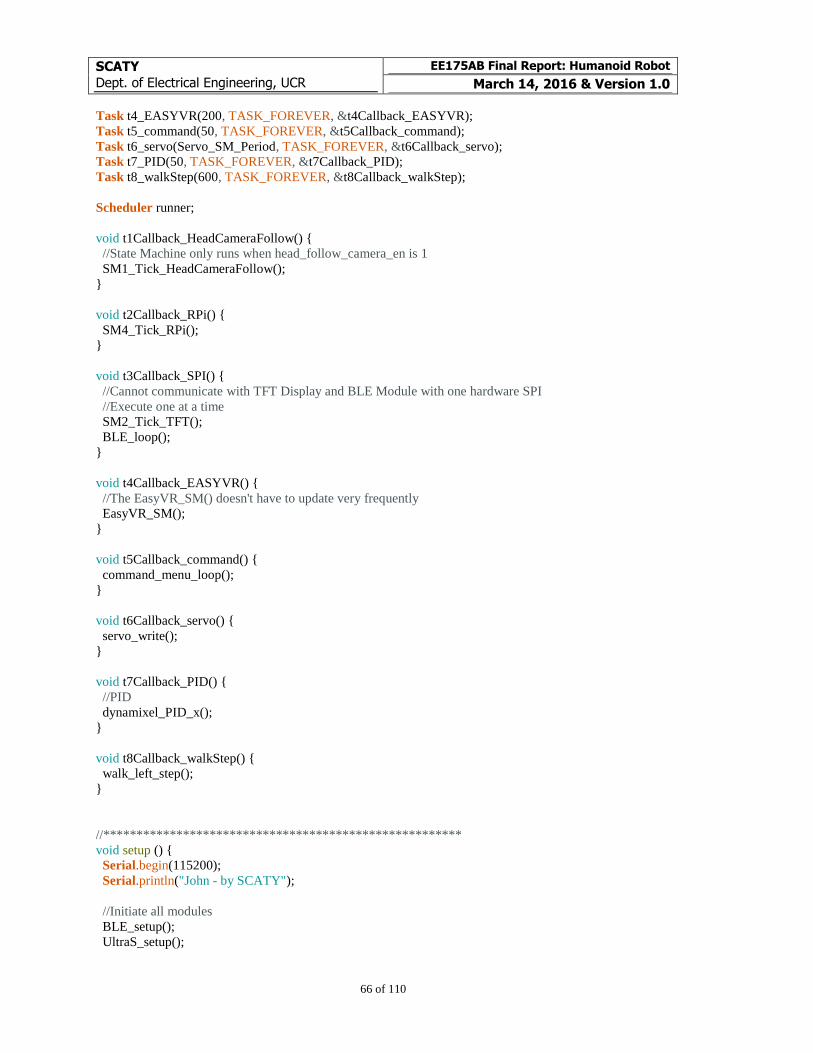
SCATY
Dept. of Electrical Engineering, UCR
EE175AB Final Report: Humanoid Robot
March 14, 2016 & Version 1.0
66 of 110
Task t4_EASYVR(200, TASK_FOREVER, &t4Callback_EASYVR);
Task t5_command(50, TASK_FOREVER, &t5Callback_command);
Task t6_servo(Servo_SM_Period, TASK_FOREVER, &t6Callback_servo);
Task t7_PID(50, TASK_FOREVER, &t7Callback_PID);
Task t8_walkStep(600, TASK_FOREVER, &t8Callback_walkStep);
Scheduler runner;
void t1Callback_HeadCameraFollow() {
//State Machine only runs when head_follow_camera_en is 1
SM1_Tick_HeadCameraFollow();
}
void t2Callback_RPi() {
SM4_Tick_RPi();
}
void t3Callback_SPI() {
//Cannot communicate with TFT Display and BLE Module with one hardware SPI
//Execute one at a time
SM2_Tick_TFT();
BLE_loop();
}
void t4Callback_EASYVR() {
//The EasyVR_SM() doesn't have to update very frequently
EasyVR_SM();
}
void t5Callback_command() {
command_menu_loop();
}
void t6Callback_servo() {
servo_write();
}
void t7Callback_PID() {
//PID
dynamixel_PID_x();
}
void t8Callback_walkStep() {
walk_left_step();
}
//******************************************************
void setup () {
Serial.begin(115200);
Serial.println("John - by SCATY");
//Initiate all modules
BLE_setup();
UltraS_setup();
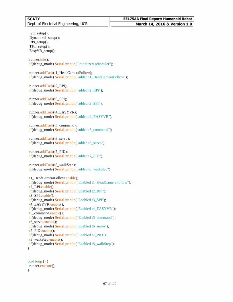
SCATY
Dept. of Electrical Engineering, UCR
EE175AB Final Report: Humanoid Robot
March 14, 2016 & Version 1.0
67 of 110
I2C_setup();
Dynamixel_setup();
RPi_setup();
TFT_setup();
EasyVR_setup();
runner.init();
if(debug_mode) Serial.println("Initialized scheduler");
runner.addTask(t1_HeadCameraFollow);
if(debug_mode) Serial.println("added t1_HeadCameraFollow");
runner.addTask(t2_RPi);
if(debug_mode) Serial.println("added t2_RPi");
runner.addTask(t3_SPI);
if(debug_mode) Serial.println("added t3_SPI");
runner.addTask(t4_EASYVR);
if(debug_mode) Serial.println("added t4_EASYVR");
runner.addTask(t5_command);
if(debug_mode) Serial.println("added t5_command");
runner.addTask(t6_servo);
if(debug_mode) Serial.println("added t6_servo");
runner.addTask(t7_PID);
if(debug_mode) Serial.println("added t7_PID");
runner.addTask(t8_walkStep);
if(debug_mode) Serial.println("added t8_walkStep");
t1_HeadCameraFollow.enable();
if(debug_mode) Serial.println("Enabled t1_HeadCameraFollow");
t2_RPi.enable();
if(debug_mode) Serial.println("Enabled t2_RPi");
t3_SPI.enable();
if(debug_mode) Serial.println("Enabled t3_SPI");
t4_EASYVR.enable();
if(debug_mode) Serial.println("Enabled t4_EASYVR");
t5_command.enable();
if(debug_mode) Serial.println("Enabled t5_command");
t6_servo.enable();
if(debug_mode) Serial.println("Enabled t6_servo");
t7_PID.enable();
if(debug_mode) Serial.println("Enabled t7_PID");
t8_walkStep.enable();
if(debug_mode) Serial.println("Enabled t8_walkStep");
}
void loop () {
runner.execute();
}
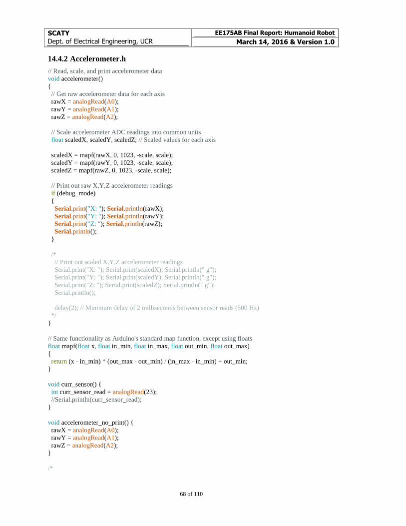
SCATY
Dept. of Electrical Engineering, UCR
EE175AB Final Report: Humanoid Robot
March 14, 2016 & Version 1.0
68 of 110
14.4.2 Accelerometer.h
// Read, scale, and print accelerometer data
void accelerometer()
{
// Get raw accelerometer data for each axis
rawX = analogRead(A0);
rawY = analogRead(A1);
rawZ = analogRead(A2);
// Scale accelerometer ADC readings into common units
float scaledX, scaledY, scaledZ; // Scaled values for each axis
scaledX = mapf(rawX, 0, 1023, -scale, scale);
scaledY = mapf(rawY, 0, 1023, -scale, scale);
scaledZ = mapf(rawZ, 0, 1023, -scale, scale);
// Print out raw X,Y,Z accelerometer readings
if (debug_mode)
{
Serial.print("X: "); Serial.println(rawX);
Serial.print("Y: "); Serial.println(rawY);
Serial.print("Z: "); Serial.println(rawZ);
Serial.println();
}
/*
// Print out scaled X,Y,Z accelerometer readings
Serial.print("X: "); Serial.print(scaledX); Serial.println(" g");
Serial.print("Y: "); Serial.print(scaledY); Serial.println(" g");
Serial.print("Z: "); Serial.print(scaledZ); Serial.println(" g");
Serial.println();
delay(2); // Minimum delay of 2 milliseconds between sensor reads (500 Hz)
*/
}
// Same functionality as Arduino's standard map function, except using floats
float mapf(float x, float in_min, float in_max, float out_min, float out_max)
{
return (x - in_min) * (out_max - out_min) / (in_max - in_min) + out_min;
}
void curr_sensor() {
int curr_sensor_read = analogRead(23);
//Serial.println(curr_sensor_read);
}
void accelerometer_no_print() {
rawX = analogRead(A0);
rawY = analogRead(A1);
rawZ = analogRead(A2);
}
/*
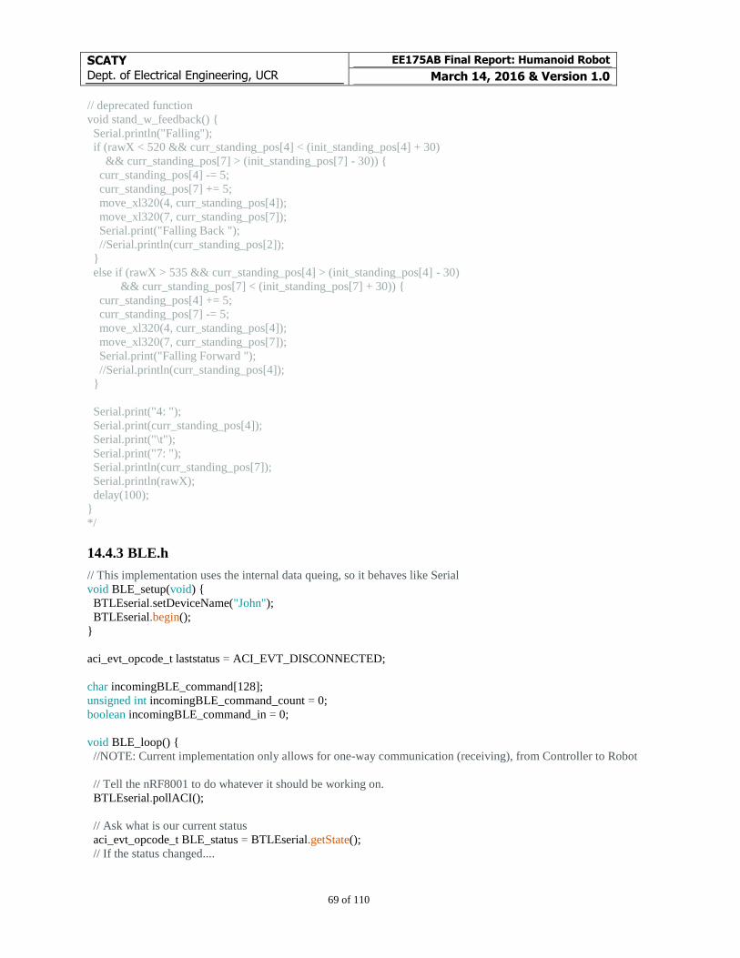
SCATY
Dept. of Electrical Engineering, UCR
EE175AB Final Report: Humanoid Robot
March 14, 2016 & Version 1.0
69 of 110
// deprecated function
void stand_w_feedback() {
Serial.println("Falling");
if (rawX < 520 && curr_standing_pos[4] < (init_standing_pos[4] + 30)
&& curr_standing_pos[7] > (init_standing_pos[7] - 30)) {
curr_standing_pos[4] -= 5;
curr_standing_pos[7] += 5;
move_xl320(4, curr_standing_pos[4]);
move_xl320(7, curr_standing_pos[7]);
Serial.print("Falling Back ");
//Serial.println(curr_standing_pos[2]);
}
else if (rawX > 535 && curr_standing_pos[4] > (init_standing_pos[4] - 30)
&& curr_standing_pos[7] < (init_standing_pos[7] + 30)) {
curr_standing_pos[4] += 5;
curr_standing_pos[7] -= 5;
move_xl320(4, curr_standing_pos[4]);
move_xl320(7, curr_standing_pos[7]);
Serial.print("Falling Forward ");
//Serial.println(curr_standing_pos[4]);
}
Serial.print("4: ");
Serial.print(curr_standing_pos[4]);
Serial.print("\t");
Serial.print("7: ");
Serial.println(curr_standing_pos[7]);
Serial.println(rawX);
delay(100);
}
*/
14.4.3 BLE.h
// This implementation uses the internal data queing, so it behaves like Serial
void BLE_setup(void) {
BTLEserial.setDeviceName("John");
BTLEserial.begin();
}
aci_evt_opcode_t laststatus = ACI_EVT_DISCONNECTED;
char incomingBLE_command[128];
unsigned int incomingBLE_command_count = 0;
boolean incomingBLE_command_in = 0;
void BLE_loop() {
//NOTE: Current implementation only allows for one-way communication (receiving), from Controller to Robot
// Tell the nRF8001 to do whatever it should be working on.
BTLEserial.pollACI();
// Ask what is our current status
aci_evt_opcode_t BLE_status = BTLEserial.getState();
// If the status changed....
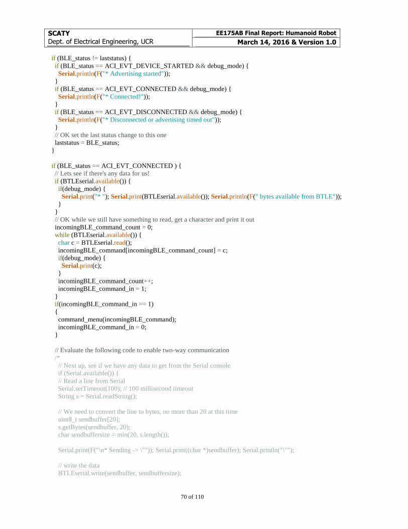
SCATY
Dept. of Electrical Engineering, UCR
EE175AB Final Report: Humanoid Robot
March 14, 2016 & Version 1.0
70 of 110
if (BLE_status != laststatus) {
if (BLE_status == ACI_EVT_DEVICE_STARTED && debug_mode) {
Serial.println(F("* Advertising started"));
}
if (BLE_status == ACI_EVT_CONNECTED && debug_mode) {
Serial.println(F("* Connected!"));
}
if (BLE_status == ACI_EVT_DISCONNECTED && debug_mode) {
Serial.println(F("* Disconnected or advertising timed out"));
}
// OK set the last status change to this one
laststatus = BLE_status;
}
if (BLE_status == ACI_EVT_CONNECTED ) {
// Lets see if there's any data for us!
if (BTLEserial.available()) {
if(debug_mode) {
Serial.print("* "); Serial.print(BTLEserial.available()); Serial.println(F(" bytes available from BTLE"));
}
}
// OK while we still have something to read, get a character and print it out
incomingBLE_command_count = 0;
while (BTLEserial.available()) {
char c = BTLEserial.read();
incomingBLE_command[incomingBLE_command_count] = c;
if(debug_mode) {
Serial.print(c);
}
incomingBLE_command_count++;
incomingBLE_command_in = 1;
}
if(incomingBLE_command_in == 1)
{
command_menu(incomingBLE_command);
incomingBLE_command_in = 0;
}
// Evaluate the following code to enable two-way communication
/*
// Next up, see if we have any data to get from the Serial console
if (Serial.available()) {
// Read a line from Serial
Serial.setTimeout(100); // 100 millisecond timeout
String s = Serial.readString();
// We need to convert the line to bytes, no more than 20 at this time
uint8_t sendbuffer[20];
s.getBytes(sendbuffer, 20);
char sendbuffersize = min(20, s.length());
Serial.print(F("\n* Sending -> \"")); Serial.print((char *)sendbuffer); Serial.println("\"");
// write the data
BTLEserial.write(sendbuffer, sendbuffersize);
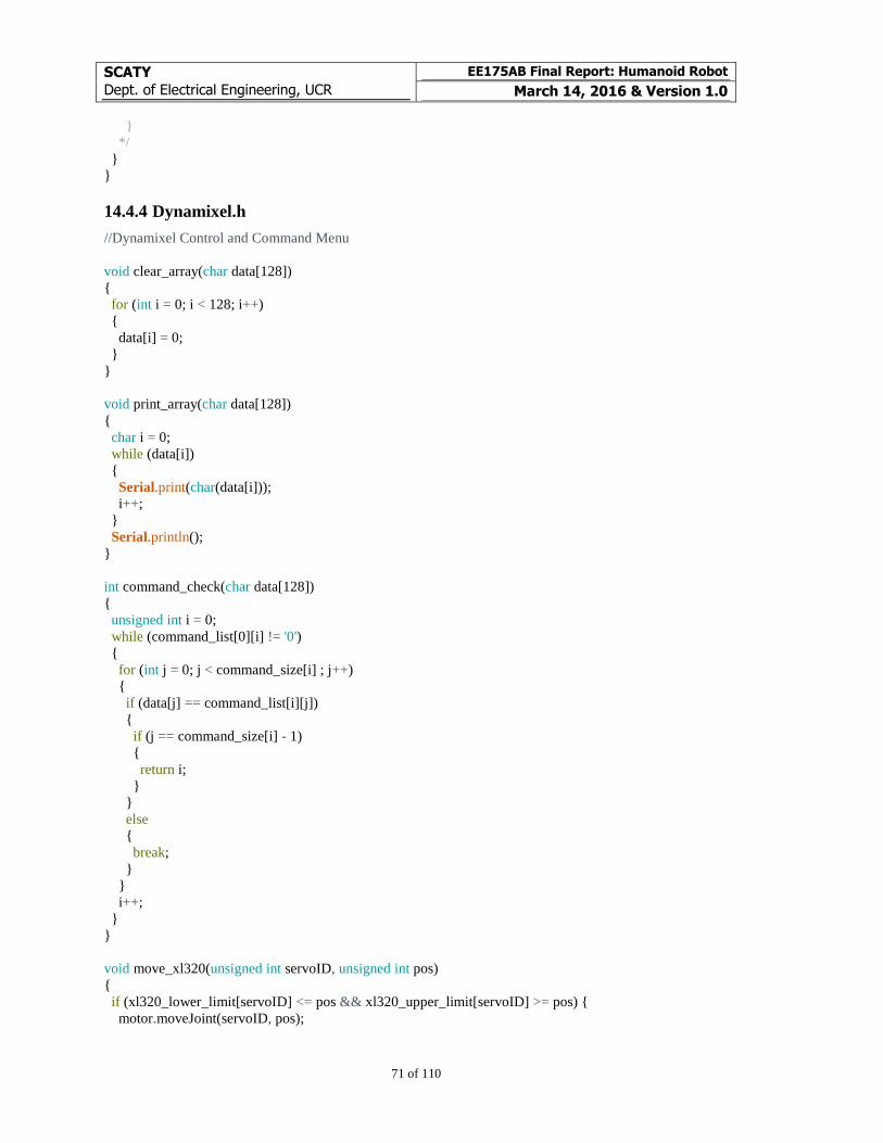
SCATY
Dept. of Electrical Engineering, UCR
EE175AB Final Report: Humanoid Robot
March 14, 2016 & Version 1.0
71 of 110
}
*/
}
}
14.4.4 Dynamixel.h
//Dynamixel Control and Command Menu
void clear_array(char data[128])
{
for (int i = 0; i < 128; i++)
{
data[i] = 0;
}
}
void print_array(char data[128])
{
char i = 0;
while (data[i])
{
Serial.print(char(data[i]));
i++;
}
Serial.println();
}
int command_check(char data[128])
{
unsigned int i = 0;
while (command_list[0][i] != '0')
{
for (int j = 0; j < command_size[i] ; j++)
{
if (data[j] == command_list[i][j])
{
if (j == command_size[i] - 1)
{
return i;
}
}
else
{
break;
}
}
i++;
}
}
void move_xl320(unsigned int servoID, unsigned int pos)
{
if (xl320_lower_limit[servoID] <= pos && xl320_upper_limit[servoID] >= pos) {
motor.moveJoint(servoID, pos);
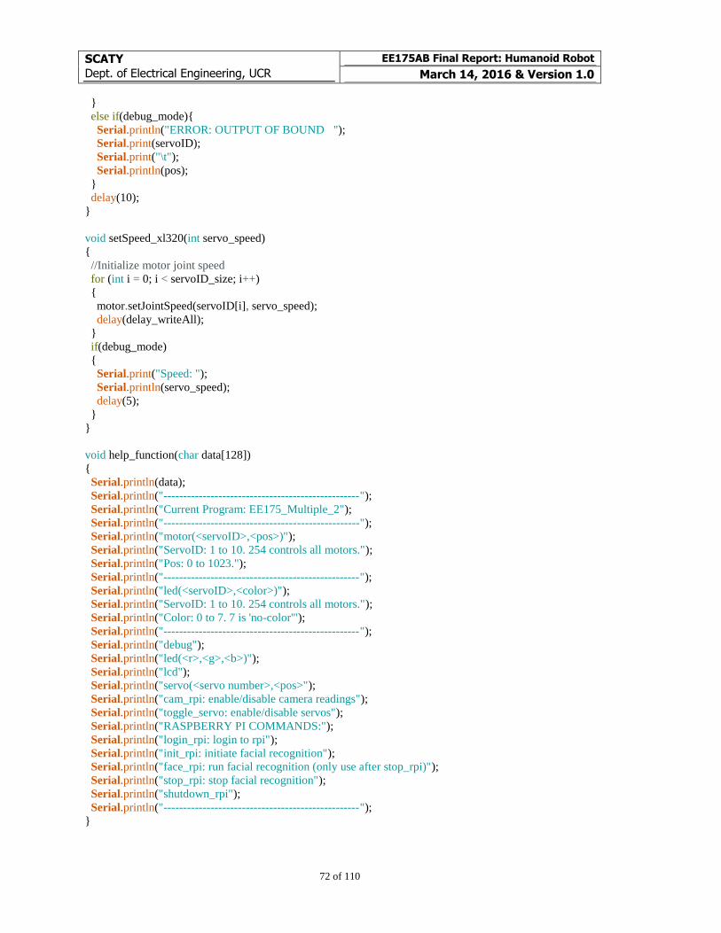
SCATY
Dept. of Electrical Engineering, UCR
EE175AB Final Report: Humanoid Robot
March 14, 2016 & Version 1.0
72 of 110
}
else if(debug_mode){
Serial.println("ERROR: OUTPUT OF BOUND ");
Serial.print(servoID);
Serial.print("\t");
Serial.println(pos);
}
delay(10);
}
void setSpeed_xl320(int servo_speed)
{
//Initialize motor joint speed
for (int i = 0; i < servoID_size; i++)
{
motor.setJointSpeed(servoID[i], servo_speed);
delay(delay_writeAll);
}
if(debug_mode)
{
Serial.print("Speed: ");
Serial.println(servo_speed);
delay(5);
}
}
void help_function(char data[128])
{
Serial.println(data);
Serial.println("--------------------------------------------------");
Serial.println("Current Program: EE175_Multiple_2");
Serial.println("--------------------------------------------------");
Serial.println("motor(<servoID>,<pos>)");
Serial.println("ServoID: 1 to 10. 254 controls all motors.");
Serial.println("Pos: 0 to 1023.");
Serial.println("--------------------------------------------------");
Serial.println("led(<servoID>,<color>)");
Serial.println("ServoID: 1 to 10. 254 controls all motors.");
Serial.println("Color: 0 to 7. 7 is 'no-color'");
Serial.println("--------------------------------------------------");
Serial.println("debug");
Serial.println("led(<r>,<g>,<b>)");
Serial.println("lcd");
Serial.println("servo(<servo number>,<pos>");
Serial.println("cam_rpi: enable/disable camera readings");
Serial.println("toggle_servo: enable/disable servos");
Serial.println("RASPBERRY PI COMMANDS:");
Serial.println("login_rpi: login to rpi");
Serial.println("init_rpi: initiate facial recognition");
Serial.println("face_rpi: run facial recognition (only use after stop_rpi)");
Serial.println("stop_rpi: stop facial recognition");
Serial.println("shutdown_rpi");
Serial.println("--------------------------------------------------");
}
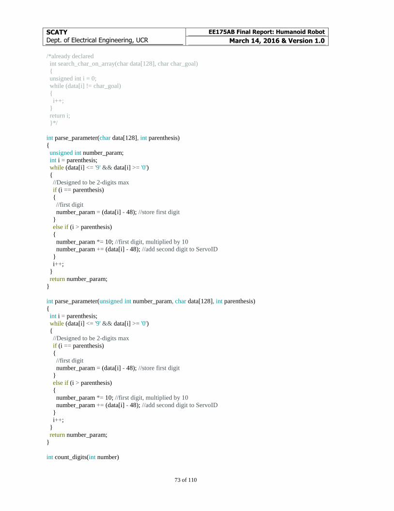
SCATY
Dept. of Electrical Engineering, UCR
EE175AB Final Report: Humanoid Robot
March 14, 2016 & Version 1.0
73 of 110
/*already declared
int search_char_on_array(char data[128], char char_goal)
{
unsigned int i = 0;
while (data[i] != char_goal)
{
i++;
}
return i;
}*/
int parse_parameter(char data[128], int parenthesis)
{
unsigned int number_param;
int i = parenthesis;
while (data[i] <= '9' && data[i] >= '0')
{
//Designed to be 2-digits max
if (i == parenthesis)
{
//first digit
number_param = (data[i] - 48); //store first digit
}
else if (i > parenthesis)
{
number_param *= 10; //first digit, multiplied by 10
number_param += (data[i] - 48); //add second digit to ServoID
}
i++;
}
return number_param;
}
int parse_parameter(unsigned int number_param, char data[128], int parenthesis)
{
int i = parenthesis;
while (data[i] <= '9' && data[i] >= '0')
{
//Designed to be 2-digits max
if (i == parenthesis)
{
//first digit
number_param = (data[i] - 48); //store first digit
}
else if (i > parenthesis)
{
number_param *= 10; //first digit, multiplied by 10
number_param += (data[i] - 48); //add second digit to ServoID
}
i++;
}
return number_param;
}
int count_digits(int number)
SCATY
Dept. of Electrical Engineering, UCR
EE175AB Final Report: Humanoid Robot
March 14, 2016 & Version 1.0
74 of 110
{
int i = 0;
while (number > 0)
{
number /= 10;
i++;
}
return i;
}
void motor_function(char data[128])
{
//disregard first 6 char: "motor("
unsigned int ServoID = 0; //stores target ServoID value
unsigned int Servo_move = 0; //stores target final position value
unsigned int array_pos = 0; //keeps track of position in array being parsed
int parenthesis = search_char_on_array(data, '(');
array_pos = parenthesis;
ServoID = parse_parameter(ServoID, data, parenthesis + 1);
array_pos += count_digits(ServoID);
//Parse first parameter
//loop as long as it is a number
array_pos += 2; //separator from first and second parameter
//could be any character as long as it's not a number
//Second parameter
//designed to fit up to 4 digits
//range of motor up to 1023
Servo_move = parse_parameter(Servo_move, data, array_pos);
if(debug_mode)
{
print_array(data); //display command entered
Serial.print("ServoID: ");
Serial.print(ServoID); //ServoID: first parameter
Serial.print("\t");
Serial.print("Move: ");
Serial.print(Servo_move); //Position: second parameter
Serial.println();
}
//Actually send the command to move the Dynamixel XL-320
//motor.moveJoint(ServoID,Servo_move); //DO NOT USE THIS ANYMORE
move_xl320(ServoID, Servo_move); //includes safety checks
delay(delay_writeAll);
}
void motor_all_function(unsigned int data[16])
{
SCATY
Dept. of Electrical Engineering, UCR
EE175AB Final Report: Humanoid Robot
March 14, 2016 & Version 1.0
75 of 110
//Actually send the command to move the Dynamixel XL-320
if(debug_mode) Serial.println("Writing to all motors");
for (unsigned int i = 0; i < 16; i++)
{
if (i == 11)
break;
//motor.moveJoint(i,data[i]); //DO NOT USE THIS ANYMORE
move_xl320(i, data[i]);
if(debug_mode)
{
Serial.print(i);
Serial.print("\t");
Serial.println(data[i]);
delay(delay_writeAll);
}
}
}
void stand_function() {
setSpeed_xl320(200);
motor_all_function(init_standing_pos);
}
void led_function(char data[128])
{
//code
unsigned int ServoID = 0;
unsigned int array_pos = 0;
unsigned int Servo_color = 0;
int parenthesis = search_char_on_array(data, '(');
array_pos = parenthesis;
ServoID = parse_parameter(ServoID, data, parenthesis + 1);
array_pos += count_digits(ServoID);
array_pos += 2;
Servo_color = parse_parameter(Servo_color, data, array_pos);
print_array(data);
if(debug_mode)
{
Serial.print("ServoID: ");
Serial.print(ServoID); //ServoID: first parameter
Serial.print("\t");
Serial.print("Color: ");
Serial.print(Servo_color); //Position: second parameter
Serial.println();
}
motor.LED(ServoID, &rgb[7]);
delay(5); //wait for first instruction to finish sending. Timer overrun
motor.LED(ServoID, &rgb[Servo_color]);
delay(5);
SCATY
Dept. of Electrical Engineering, UCR
EE175AB Final Report: Humanoid Robot
March 14, 2016 & Version 1.0
76 of 110
}
void setspeed_function(char data[128])
{
//code
unsigned int ServoSpeed = 0;
unsigned int array_pos = 0;
int parenthesis = search_char_on_array(data, '(');
array_pos = parenthesis;
ServoSpeed = parse_parameter(ServoSpeed, data, parenthesis + 1);
if(debug_mode)
{
Serial.print("Servo Speed: ");
Serial.print(ServoSpeed); //ServoID: first parameter
Serial.println();
}
setSpeed_xl320(ServoSpeed);
}
void reset_switch() {
digitalWrite(21, LOW);
delay(1000);
digitalWrite(21, HIGH);
}
void right_leg_PID()
{
Input = (analogRead(A0));
if (Input > (Setpoint - 10) && Input < (Setpoint + 10))
Input = Setpoint;
Input_y = (analogRead(A1));
if (Input_y > (Setpoint_y - 10) && Input_y < (Setpoint_y + 10))
Input_y = Setpoint_y;
myPID.Compute();
myPID3.Compute();
move_xl320(4, (int)Output);
if (!y_PID_disable)
{
move_xl320(5, (int)Output3);
}
}
void Dynamixel_setup()
{
Serial1.begin(115200); //XL-320 baud rate
pinMode(23, INPUT);
pinMode(21, OUTPUT);
digitalWrite(21, LOW);
delay(1000);
digitalWrite(21, HIGH);
delay(1000);
Serial.println("Initializing");
SCATY
Dept. of Electrical Engineering, UCR
EE175AB Final Report: Humanoid Robot
March 14, 2016 & Version 1.0
77 of 110
motor.begin(Serial1); //Link XL320 motor object to Software Serial motor_serial
setSpeed_xl320(200);
delay(5);
//Set motors to standing position
motor_all_function(init_standing_pos);
//turn the PID on
myPID.SetMode(AUTOMATIC);
myPID2.SetMode(AUTOMATIC);
myPID3.SetMode(AUTOMATIC);
myPID.SetOutputLimits(init_standing_pos[4]-xl320_PID_delta_x, init_standing_pos[4]+xl320_PID_delta_x);
myPID2.SetOutputLimits(init_standing_pos[7]-xl320_PID_delta_x, init_standing_pos[7]+xl320_PID_delta_x);
myPID3.SetOutputLimits(450, 550);
PID_sole_l.SetMode(AUTOMATIC);
PID_sole_r.SetMode(AUTOMATIC);
PID_sole_l.SetOutputLimits(init_standing_pos[9]-5,init_standing_pos[9]+5);
PID_sole_r.SetOutputLimits(init_standing_pos[2]-5,init_standing_pos[2]+5);
Setpoint = 525;
Setpoint_y = 498;
y_PID_disable = 1;
myPID.SetSampleTime(50);
myPID2.SetSampleTime(50);
PID_sole_l.SetSampleTime(50);
PID_sole_r.SetSampleTime(50);
}
#define NUM_READS 20
float readAnalog(int sensorpin){
// read multiple values and sort them to take the mode
int sortedValues[NUM_READS];
for(int i=0;i<NUM_READS;i++){
int value = analogRead(sensorpin);
int j;
if(value<sortedValues[0] || i==0){
j=0; //insert at first position
}
else{
for(j=1;j<i;j++){
if(sortedValues[j-1]<=value && sortedValues[j]>=value){
// j is insert position
break;
}
}
}
for(int k=i;k>j;k--){
SCATY
Dept. of Electrical Engineering, UCR
EE175AB Final Report: Humanoid Robot
March 14, 2016 & Version 1.0
78 of 110
// move all values higher than current reading up one position
sortedValues[k]=sortedValues[k-1];
}
sortedValues[j]=value; //insert current reading
}
//return scaled mode of 10 values
float returnval = 0;
for(int i=NUM_READS/2-5;i<(NUM_READS/2+5);i++){
returnval +=sortedValues[i];
}
returnval = returnval/10;
return returnval;
}
void dynamixel_PID_x()
{
if(PID_X_EN || PID_SOLE_EN)
{
Input = readAnalog(A0);
if(debug_mode)
Serial.println(Input);
}
if(PID_X_EN)
{
myPID.Compute();
myPID2.Compute();
move_xl320(4,(int)Output);
move_xl320(7,(int)Output2);
}
if(PID_SOLE_EN)
{
PID_sole_l.Compute();
PID_sole_r.Compute();
move_xl320(9,(int)Output_sole_l);
move_xl320(2,(int)Output_sole_r);
}
}
enum walk_left_sm_Status
{walk_left_sm_init,walk_left_sm_weight,walk_left_sm_lift,walk_left_sm_forward,walk_left_sm_stable,walk_left_
sm_stop} walk_left_sm_status;
void walk_left_step()
{
switch(walk_left_sm_status)
{
case walk_left_sm_init:
break;
case walk_left_sm_weight:
PID_X_EN = 0;
PID_SOLE_EN = 0;
setSpeed_xl320(80);
move_xl320(4,395);
SCATY
Dept. of Electrical Engineering, UCR
EE175AB Final Report: Humanoid Robot
March 14, 2016 & Version 1.0
79 of 110
move_xl320(1,218);
move_xl320(5,530);
//move_xl320(6,530);
move_xl320(4,420);
move_xl320(7,605);
setSpeed_xl320(500);
move_xl320(4,390);
break;
case walk_left_sm_lift:
//move_xl320(4,380);
setSpeed_xl320(800);
move_xl320(4,375);
move_xl320(8,200);
move_xl320(7,800);
move_xl320(9,380);
move_xl320(1,200);
move_xl320(2,590);
break;
case walk_left_sm_forward:
move_xl320(8,400);
move_xl320(9,480);
move_xl320(7,670);
move_xl320(1,180);
move_xl320(6,545);
move_xl320(2,580);
move_xl320(10,550);
move_xl320(5,510);
break;
case walk_left_sm_stable:
setSpeed_xl320(300);
move_xl320(4,440);
move_xl320(7,680);
move_xl320(2,580);
move_xl320(9,490);
Setpoint = 530;
myPID.SetOutputLimits(440-10, 440+10);
myPID2.SetOutputLimits(680-10, 680+10);
PID_sole_l.SetOutputLimits(490-10,490+10);
PID_sole_r.SetOutputLimits(580-10,580+10);
PID_X_EN = 1;
PID_SOLE_EN = 1;
break;
default:
break;
}
switch(walk_left_sm_status)
{
case walk_left_sm_init:
if(walk_left_sm_en)
SCATY
Dept. of Electrical Engineering, UCR
EE175AB Final Report: Humanoid Robot
March 14, 2016 & Version 1.0
80 of 110
{
UltraS_loop();
if(distance >= 10)
{
walk_left_sm_status = walk_left_sm_weight;
}
}
else
walk_left_sm_status = walk_left_sm_init;
break;
case walk_left_sm_weight:
walk_left_sm_status = walk_left_sm_lift;
break;
case walk_left_sm_lift:
walk_left_sm_status = walk_left_sm_forward;
break;
case walk_left_sm_forward:
walk_left_sm_status = walk_left_sm_stable;
break;
case walk_left_sm_stable:
walk_left_sm_status = walk_left_sm_stop;
case walk_left_sm_stop:
if(walk_left_sm_en)
walk_left_sm_status = walk_left_sm_stop;
else
walk_left_sm_status = walk_left_sm_init;
break;
default:
break;
}
}
unsigned int right_leg_counter = 0;
void stand_in_right_leg()
{
right_leg_counter++;
if (right_leg_counter == 4800) {
y_PID_disable = 0;
setSpeed_xl320(50);
Setpoint = 510;
Setpoint_y = 498;
}
else if (right_leg_counter == 5600) {
move_xl320(10, 520);
move_xl320(1, 205);
}
else if (right_leg_counter == 6400) {
Setpoint_y = 495;
//move_xl320(4, 480);
move_xl320(10, 530);
move_xl320(1, 210);
}
else if (right_leg_counter == 7200) {
Setpoint_y = 490;
SCATY
Dept. of Electrical Engineering, UCR
EE175AB Final Report: Humanoid Robot
March 14, 2016 & Version 1.0
81 of 110
//move_xl320(4, 485);
move_xl320(10, 540);
move_xl320(1, 220);
}
else if (right_leg_counter == 8000) {
Setpoint_y = 486;
//move_xl320(4, 490);
move_xl320(10, 550);
move_xl320(1, 228);
move_xl320(5, 550);
move_xl320(6, 575);
move_xl320(7, 771);
move_xl320(8, 272);
}
}
//*************************** Menu to Execute Commands
******************************************
void command_menu(char incomingCommand_stream[128])
{
switch (command_check(incomingCommand_stream))
{
case 0:
help_function(incomingCommand_stream);
break;
case 1:
motor_function(incomingCommand_stream);
break;
case 2:
led_function(incomingCommand_stream);
break;
case 3:
//bow_function();
curr_sensor();
break;
case 4:
//walk_function();
//servo_map(0, 200);
//servo_map(3, 0);
walk_left_sm_en = walk_left_sm_en? 0:1;
Serial.print("Walk: ");
Serial.println(walk_left_sm_en);
break;
case 5:
stand_function();
servo_map(0, init_rest_arms[0]);
servo_map(3, init_rest_arms[3]);
break;
case 6:
setspeed_function(incomingCommand_stream);
SCATY
Dept. of Electrical Engineering, UCR
EE175AB Final Report: Humanoid Robot
March 14, 2016 & Version 1.0
82 of 110
break;
case 7:
//moveRight();
//rightLeg();
//Serial.println("Moving right leg");
accelerometer();
break;
case 8:
//leftLeg();
//moveLeft();
//Serial.println("Moving left leg");
reset_switch();
break;
case 9:
init_rpi();
break;
case 10:
login_rpi();
break;
case 11:
stop_rpi();
break;
case 12:
ip();
break;
case 13:
shutdown_rpi();
break;
case 14:
//cam_rpi
IMAGE_TRACKING_EN = ~(IMAGE_TRACKING_EN);
break;
case 15:
//toggle_servo
newline_rpi();
break;
case 16:
//debug
debug_mode = ~(debug_mode);
Serial.print("debug: ");
Serial.println(debug_mode);
break;
case 17:
skip_rpi_init = 1;
Serial.print("Skipping RPi: ");
Serial.println(skip_rpi_init);
break;
case 18:
head_follow_camera_en = ~head_follow_camera_en;
break;
case 19:
//arms_up
servo_update(0,200,4000);
servo_update(3,0,4000);
break;
SCATY
Dept. of Electrical Engineering, UCR
EE175AB Final Report: Humanoid Robot
March 14, 2016 & Version 1.0
83 of 110
case 20:
//arms_down
servo_update(0, init_rest_arms[0],4000);
servo_update(3, init_rest_arms[3],4000);
break;
case 21:
//easyvr_en
EASYVR_SM_EN = EASYVR_SM_EN? 0:1;
Serial.print("EASYVR_EN = ");
Serial.println(EASYVR_SM_EN);
break;
case 22:
//right_hand
servo_map(0,200);
Serial.println("Right Hand");
break;
case 23:
//left_hand
servo_map(3,0);
Serial.println("Left Hand");
break;
case 24:
servo_map(0,init_rest_arms[0]);
Serial.println("Right Hand Down");
break;
case 25:
servo_map(3,init_rest_arms[3]);
Serial.println("Left Hand Down");
break;
case 26:
motor_function(incomingCommand_stream);
break;
default:
ERROR_NOT_FOUND(incomingCommand_stream);
break;
}
clear_array(incomingCommand); //clear array storing command buffer
}
void command_menu_loop() {
unsigned char incomingCommand_size = 0;
flag = 0;
//Wait for incoming user input on Serial Terminal
if (Serial.available())
{
incomingCommand_size = Serial.available(); //store the size of the input on a variable
//Read and store all incoming data on UART on incomingCommand array
for (int i = 0; i < incomingCommand_size; i++)
{
incomingCommand[i] = Serial.read(); //store the data on the buffer on an array
}
command_menu(incomingCommand);
SCATY
Dept. of Electrical Engineering, UCR
EE175AB Final Report: Humanoid Robot
March 14, 2016 & Version 1.0
84 of 110
}
}
14.4.5 EasyVR.h
// EasyVR - Voice Recognition module
// Preprogrammed behaviors for voice commands
void EasyVR_setup() {
Serial2.begin(9600);
while(!easyvr.detect())
{
if(debug_mode) Serial.println("EasyVR not detected!");
}
easyvr.setPinOutput(EasyVR::IO1, LOW);
if(debug_mode) Serial.println("EasyVR detected!");
easyvr.setTimeout(5);
easyvr.setLanguage(0);
group = EasyVR::TRIGGER; //<-- start group (customize)
}
void action();
enum EasyVR_SM_Status {EasyVR_SM_init, EasyVR_SM_1, EasyVR_SM_2, EasyVR_SM_3, EasyVR_SM_4}
EasyVR_SM_status;
void EasyVR_SM()
{
switch (EasyVR_SM_status)
{
case EasyVR_SM_1:
easyvr.setPinOutput(EasyVR::IO1, HIGH); // LED on (listening)
if(debug_mode)
{
Serial.print("Say a command in Group ");
Serial.println(group);
}
easyvr.recognizeCommand(group);
break;
case EasyVR_SM_2:
break;
case EasyVR_SM_3:
easyvr.setPinOutput(EasyVR::IO1, LOW); // LED off
idx = easyvr.getWord();
if (idx >= 0)
{
// built-in trigger (ROBOT)
// group = GROUP_X; <-- jump to another group X
return;
}
idx = easyvr.getCommand();
SCATY
Dept. of Electrical Engineering, UCR
EE175AB Final Report: Humanoid Robot
March 14, 2016 & Version 1.0
85 of 110
if (idx >= 0)
{
// print debug message
uint8_t train = 0;
char name[32];
if(debug_mode)
{
Serial.print("Command: ");
Serial.print(idx);
}
if (easyvr.dumpCommand(group, idx, name, train))
{
if(debug_mode)
{
Serial.print(" = ");
Serial.println(name);
}
}
else
{
if(debug_mode) Serial.println();
}
easyvr.playSound(0, EasyVR::VOL_FULL);
// perform some action
action();
}
else // errors or timeout
{
if (easyvr.isTimeout())
{
if(debug_mode) Serial.println("Timed out, try again...");
}
int16_t err = easyvr.getError();
if (err >= 0)
{
if(debug_mode)
{
Serial.print("Error ");
Serial.println(err, HEX);
}
}
}
break;
default:
break;
}
switch (EasyVR_SM_status)
{
case EasyVR_SM_init:
if(EASYVR_SM_EN)
EasyVR_SM_status = EasyVR_SM_1;
else
EasyVR_SM_status = EasyVR_SM_init;
break;
case EasyVR_SM_1:
SCATY
Dept. of Electrical Engineering, UCR
EE175AB Final Report: Humanoid Robot
March 14, 2016 & Version 1.0
86 of 110
if(EASYVR_SM_EN)
EasyVR_SM_status = EasyVR_SM_2;
else
EasyVR_SM_status = EasyVR_SM_init;
break;
case EasyVR_SM_2:
if(EASYVR_SM_EN == 0)
{
EasyVR_SM_status = EasyVR_SM_init;
}
else if (!easyvr.hasFinished())
{
EasyVR_SM_status = EasyVR_SM_2;
}
else
{
EasyVR_SM_status = EasyVR_SM_3;
}
break;
case EasyVR_SM_3:
if(EASYVR_SM_EN)
{
EasyVR_SM_status = EasyVR_SM_4;
}
else
{
EasyVR_SM_status = EasyVR_SM_init;
}
break;
case EasyVR_SM_4:
EasyVR_SM_status = EasyVR_SM_1;
break;
default:
break;
}
//Serial.println(EasyVR_SM_status);
}
void action()
{
switch (group)
{
case GROUP_0:
switch (idx)
{
case G0_JOHN:
group = GROUP_1;
//mood = HAPPY;
command_menu("led(254,2)");
activity = 1;
break;
}
break;
case GROUP_1:
switch (idx)
SCATY
Dept. of Electrical Engineering, UCR
EE175AB Final Report: Humanoid Robot
March 14, 2016 & Version 1.0
87 of 110
{
case G1_BOW:
group = GROUP_0;
break;
case G1_STOP:
group = GROUP_0;
command_menu("stop_init");
delay(100);
command_menu("led(254,4)");
break;
case G1_WALK:
group = GROUP_0;
break;
case G1_RIGHT:
group = GROUP_0;
break;
case G1_LEFT:
group = GROUP_0;
break;
case G1_LIGHT_RED:
group = GROUP_0;
command_menu("led(254,0)");
break;
case G1_LIGHT_GREEN:
group = GROUP_0;
command_menu("led(254,1)");
break;
case G1_LIGHT_WHITE:
group = GROUP_0;
command_menu("led(254,6)");
break;
case G1_LIGHT_YELLOW:
group = GROUP_0;
command_menu("led(254,3)");
break;
case G1_LIGHT_OFF:
group = GROUP_0;
command_menu("led(254,7)");
break;
case G1_HELLO:
group = GROUP_0;
command_menu("led(254,5)");
Serial3.println("echo \"Hello. How are you doing?\" | festival --tts");
Serial.println("hello");
break;
case G1_GOODBYE:
group = GROUP_0;
command_menu("led(254,5)");
servo_map(0,init_rest_arms[0]);
servo_map(3,init_rest_arms[3]);
//mood = SAD;
break;
case G1_GOOD_NIGHT:
group = GROUP_0;
command_menu("led(254,5)");
SCATY
Dept. of Electrical Engineering, UCR
EE175AB Final Report: Humanoid Robot
March 14, 2016 & Version 1.0
88 of 110
break;
case G1_SLEEP:
group = GROUP_0;
command_menu("led(254,7)");
activity = 0;
command_menu("stop_rpi");
delay(1000);
command_menu("shutdown_rpi");
break;
case G1_IP:
group = GROUP_0;
command_menu("led(254,5)");
command_menu("ip");
break;
case G1_DANCE:
group = GROUP_0;
command_menu("led(254,5)");
Serial3.println("echo \"I don't want to dance\" | festival --tts");
delay(500);
servo_map(6,init_rest_arms[6]-15);
delay(400);
servo_map(6,init_rest_arms[6]+15);
delay(400);
servo_map(6,init_rest_arms[6]-15);
delay(400);
servo_map(6,init_rest_arms[6]);
break;
case G1_MUSIC:
group = GROUP_0;
command_menu("led(254,5)");
break;
case G1_CAMERA:
group = GROUP_0;
command_menu("led(254,5)");
IMAGE_TRACKING_EN = ~IMAGE_TRACKING_EN;
break;
case G1_KICK:
group = GROUP_0;
command_menu("led(254,5)");
break;
case G1_HANDS_UP:
group = GROUP_0;
command_menu("led(254,5)");
servo_map(0,200);
servo_map(3,0);
//mood = EXCITED;
break;
case G1_RIGHT_HAND:
group = GROUP_0;
command_menu("led(254,5)");
servo_map(0,200);
break;
case G1_LEFT_HAND:
group = GROUP_0;
command_menu("led(254,5)");
SCATY
Dept. of Electrical Engineering, UCR
EE175AB Final Report: Humanoid Robot
March 14, 2016 & Version 1.0
89 of 110
servo_map(3,0);
break;
case G1_RED:
group = GROUP_0;
command_menu("led(254,0)");
break;
case G1_GREEN:
group = GROUP_0;
command_menu("led(254,1)");
break;
case G1_FIND_ME:
group = GROUP_0;
command_menu("led(254,5)");
break;
default:
break;
}
break;
}
}
14.4.6 Head_Arms.h
// Servo Board, communication via I2C
// Upper Body = Head and Arms
void I2C_setup(){
pwm.begin();
pwm.setPWMFreq(60); //this frequency seems to work just fine
// save I2C bitrate
uint8_t twbrbackup = TWBR;
// must be changed after calling Wire.begin() (inside pwm.begin())
TWBR = 12; // upgrade to 400KHz
for(int i = 0; i < 8; i++){
servo_map(motor_joint[i],init_rest_arms[i]);
delay(20);
}
}
void servo_map(int servo_id, int angle){
int pulse = 0;
if(angle > 180)
angle = 180;
else if(angle < 0)
angle = 0;
pulse = map(angle,0,180,SERVOMIN,SERVOMAX);
pwm.setPWM(servo_id,0,pulse); //updates the PCA9685 PWM pulse
}
void servo_update(int servo_number, int servo_pos, int servo_duration)
{
servo_sm_update_en = 1;
target_arms_pos[servo_number] = servo_pos;
SCATY
Dept. of Electrical Engineering, UCR
EE175AB Final Report: Humanoid Robot
March 14, 2016 & Version 1.0
90 of 110
target_arms_time[servo_number] = servo_duration;
}
enum Servo_SM_Status {Servo_SM_init,Servo_SM_wait,Servo_SM_move} Servo_SM_status;
void servo_write()
{
switch(Servo_SM_status)
{
case Servo_SM_init:
break;
case Servo_SM_wait:
break;
case Servo_SM_move:
for(int i = 0; i < 10; i++)
{
if(target_arms_pos[i] != curr_arms_pos[i] && target_arms_time[i] >= 0)
{
if(target_arms_time[i] == 0 || target_arms_time[i] < Servo_SM_Period)
target_arms_time[i] = Servo_SM_Period;
curr_arms_pos[i] += (target_arms_pos[i] - curr_arms_pos[i])/(target_arms_time[i]/Servo_SM_Period);
servo_map(i,target_arms_pos[i]);
target_arms_time[i] -= Servo_SM_Period;
if(target_arms_time <= 0)
{
target_arms_time[i] = -1;
servo_sm_update_en = 0;
}
else
servo_sm_update_en = 1;
}
}
break;
default:
break;
}
switch(Servo_SM_status)
{
case Servo_SM_init:
Servo_SM_status = Servo_SM_wait;
break;
case Servo_SM_wait:
if(servo_sm_update_en)
Servo_SM_status = Servo_SM_move;
else
Servo_SM_status = Servo_SM_wait;
break;
case Servo_SM_move:
Servo_SM_status = Servo_SM_wait;
break;
default:
break;
}
}
SCATY
Dept. of Electrical Engineering, UCR
EE175AB Final Report: Humanoid Robot
March 14, 2016 & Version 1.0
91 of 110
//--------- Head Camera Follow ------
//SM1_Tick_HeadCameraFollow() updates servo position
//Based on camera input
//Based on other factors too
unsigned long prevMillis1 = 0;
unsigned long prevMillis3 = 0;
enum SM1_States {SM1_init, SM1_wait, SM1_follow} SM1_state;
void SM1_Tick_HeadCameraFollow()
{
delta_camera_x = prev_camera_x - camera_x;
delta_camera_y = prev_camera_y - camera_y;
//follow_camera = (abs(delta_camera_x)>x_threshold||abs(delta_camera_y)>y_threshold)?1:0;
switch (SM1_state)
{
case SM1_init:
break;
case SM1_follow:
if (camera_x < 20)
servo_base_pos += 1;
else if (camera_x > 60)
servo_base_pos -= 1;
if (camera_y < 15)
servo_tilt_pos -= 1;
else if (camera_y > 45)
servo_tilt_pos += 1;
if (servo_base_pos >= servo_base_pos_upper)
servo_base_pos = servo_base_pos_upper;
else if (servo_base_pos <= servo_base_pos_lower)
servo_base_pos = servo_base_pos_lower;
if (servo_tilt_pos >= servo_tilt_pos_upper)
servo_tilt_pos = servo_tilt_pos_upper;
else if (servo_tilt_pos <= servo_tilt_pos_lower)
servo_tilt_pos = servo_tilt_pos_lower;
if(servo_base_pos != prevServo_base_pos)
{
servo_map(motor_joint[6],servo_base_pos);
prevServo_base_pos = servo_base_pos;
}
if(servo_tilt_pos != prevServo_tilt_pos)
{
servo_map(motor_joint[7],servo_tilt_pos);
prevServo_tilt_pos = servo_tilt_pos;
}
break;
default:
break;
SCATY
Dept. of Electrical Engineering, UCR
EE175AB Final Report: Humanoid Robot
March 14, 2016 & Version 1.0
92 of 110
}
switch (SM1_state)
{
case SM1_init:
SM1_state = SM1_follow;
break;
case SM1_wait:
if(head_follow_camera_en == 1)
SM1_state = SM1_follow;
else
SM1_state = SM1_wait;
case SM1_follow:
if (follow_camera && head_follow_camera_en)
SM1_state = SM1_follow;
else
SM1_state = SM1_wait;
default:
break;
}
}
//----- end of State Machine ------
14.4.7 RPi.h
//Raspberry Pi 2
//Computer Vision and Text to Speech
void RPi_setup()
{
Serial3.begin(115200);
}
void login_rpi()
{
Serial3.println("pi");
Serial.println("pi");
delay(100);
Serial3.println("raspberry");
Serial.println("password: *********");
while (Serial3.available()) {
char c = Serial3.read();
Serial.print(c);
}
}
void init_rpi()
{
Serial.println("Initiating Facial Recognition");
Serial3.println("python /home/pi/Documents/python27/picam_face_color_3_textonly.py &");
Serial.println("picam_face_color_3.py");
}
char ip_address_stream[50];

SCATY
Dept. of Electrical Engineering, UCR
EE175AB Final Report: Humanoid Robot
March 14, 2016 & Version 1.0
93 of 110
void ip()
{
Serial3.println("hostname -I");
if(Serial3.available())
{
short incomingStream = Serial3.available();
for(int i = 0; i < incomingStream; i++)
{
ip_address_stream[i] = Serial3.read();
}
Serial.println(ip_address_stream);
}
delay(100);
Serial3.println("cd /home/pi/Documents/custom");
delay(100);
Serial3.println("./ip_echo.sh");
Serial.print("IP ADDRESS: ");
Serial.println(ip_address_stream);
Serial3.flush();
}
void stop_rpi()
{
Serial3.write('\x03');
Serial.write("^C");
Serial3.flush();
Serial3.println("kill %");
Serial.println("stopping tasks");
Serial3.flush();
}
void shutdown_rpi()
{
Serial3.write('\x03');
delay(1000);
Serial3.println("sudo halt");
Serial.println("sudo halt");
delay(1000);
while (Serial3.available()) {
char c = Serial3.read();
Serial.print(c);
}
}
void cam_rpi()
{
camera_flag = !camera_flag;
Serial.print("Camera Status: ");
Serial.println(camera_flag);
}
void ERROR_NOT_FOUND(char data[128])
{
//code
Serial.print("ERROR: ");
SCATY
Dept. of Electrical Engineering, UCR
EE175AB Final Report: Humanoid Robot
March 14, 2016 & Version 1.0
94 of 110
Serial.println(data);
}
void newline_rpi()
{
while (Serial3.available()) {
char c = Serial3.read();
Serial.print(c);
}
Serial3.println();
Serial.println("NEWLINE");
while (Serial3.available()) {
char c = Serial3.read();
Serial.print(c);
}
}
void debug_mode_init()
{
debug_mode = !debug_mode;
Serial.print("Debug mode: ");
Serial.println(debug_mode);
}
void init_array(char array[], int array_size)
{
for (int i = 0; i < array_size; i++)
{
array[i] = 0;
}
}
bool input_cam()
{
if (Serial3.available())
{
init_array(serial3_incoming, 128);
serial3_size = Serial3.available();
for (int i = 0; i < serial3_size; i++)
{
serial3_incoming[i] = Serial3.read();
}
//delay(20);
//Serial.print(serial3_incoming);
//delay(20);
return true;
}
else
return false;
}
int search_int_on_array(char data[128], unsigned int start_search)
{
SCATY
Dept. of Electrical Engineering, UCR
EE175AB Final Report: Humanoid Robot
March 14, 2016 & Version 1.0
95 of 110
unsigned int i = start_search;
while (data[i] < '0' || data[i] > '9')
{
i++;
}
return i;
}
int search_char_on_array(char data[128], char char_goal)
{
unsigned int i = 0;
while (data[i] != char_goal)
{
i++;
}
return i;
}
//----------- State Machine for Raspberry Pi --------------
unsigned long prevMillis4 = 0;
enum SM4_Status {SM4_init, SM4_pre_login, SM4_login, SM4_login_wait, SM4_initRPi, SM4_initRPi_wait,
SM4_wait, SM4_read, SM4_update_cam} SM4_status;
unsigned int x_size = 0, y_size = 0, h_size = 0, t_size = 0;
unsigned int int_start = 0;
unsigned int temp_int_start;
unsigned int RPi_init_count = 0;
void SM4_Tick_RPi()
{
switch (SM4_status)
{
case SM4_pre_login:
break;
case SM4_login:
login_rpi();
break;
case SM4_login_wait:
break;
case SM4_initRPi:
init_rpi();
break;
case SM4_initRPi_wait:
break;
case SM4_wait:
break;
case SM4_read:
count_last_time_seen++;
break;
case SM4_update_cam:
if(mood != EXCITED)
mood = HAPPY;
activity = 1;
activity_counter = 0;
SCATY
Dept. of Electrical Engineering, UCR
EE175AB Final Report: Humanoid Robot
March 14, 2016 & Version 1.0
96 of 110
first_reading_taken = 1;
input_cam();
int_start = search_int_on_array(serial3_incoming, 0);
x = parse_parameter(serial3_incoming, int_start);
x_size = count_digits(x);
int_start = search_int_on_array(serial3_incoming, int_start + x_size + 1);
y = parse_parameter(serial3_incoming, int_start);
y_size = count_digits(y);
int_start = search_int_on_array(serial3_incoming, int_start + y_size + 1);
h = parse_parameter(serial3_incoming, int_start);
h_size = count_digits(h);
int_start = search_int_on_array(serial3_incoming, int_start + h_size + 1);
t = parse_parameter(serial3_incoming, int_start);
t_size = count_digits(t);
camera_x = x;
camera_y = y;
camera_h = h;
camera_t = t;
/*
//t = 1; red
if(camera_t == 1)
{
command_menu("led(254,0)");
}
else if(camera_t == 2)
{
//t = 2; green
command_menu("led(254,1)");
}
else if(camera_t == 0)
{
Serial3.println("echo \"I see you\" | festival --tts");
}
*/
if(t == 0)
{
mood = EXCITED;
}
else if(t == 1 || t == 2)
{
mood = HAPPY;
}
else
{
mood = FACE_NORMAL;
}
if(debug_mode == 1)
{
Serial.print(x);
Serial.print("\t");
Serial.print(y);
SCATY
Dept. of Electrical Engineering, UCR
EE175AB Final Report: Humanoid Robot
March 14, 2016 & Version 1.0
97 of 110
Serial.print("\t");
Serial.print(h);
Serial.print("\t");
Serial.println(t);
if(prev_t != t)
{
if(t == 1)
{
Serial3.println("echo \"Red\" | festival --tts");
}
else if(t == 2)
{
Serial3.println("echo \"Green\" | festival --tts");
}
else if(t == 0)
{
Serial3.println("echo \"I see you\" | festival --tts");
}
}
prev_t = t;
/*
for(int i=0; i < 10; i++)
{
for(int j = 0; j < 20; j++)
{
if(i==0 || i == 9)
Serial.print("-");
//else if(j <= (20 - (x/x_proportion) - (h/x_proportion)) && j >= (20 - (x/x_proportion)) && i >=
(y/y_proportion) && i <= ((y/y_proportion) + (h/y_proportion)))
else if(j == (20 - (x/x_proportion) - (h/x_proportion)/2) && i == ((y/y_proportion) + (h/y_proportion)/2))
Serial.print("*");
else
Serial.print(" ");
}
Serial.println();
}*/
}
count_last_time_seen = 0;
follow_camera = 1;
break;
default:
break;
}
switch (SM4_status)
{
case SM4_init:
SM4_status = SM4_pre_login;
break;
case SM4_pre_login:
SCATY
Dept. of Electrical Engineering, UCR
EE175AB Final Report: Humanoid Robot
March 14, 2016 & Version 1.0
98 of 110
if(RPi_init_count > (25000/SM4_Period))
{
SM4_status = SM4_login;
RPi_init_count = 0;
}
else if(skip_rpi_init == 1)
{
SM4_status = SM4_wait;
}
else
SM4_status = SM4_pre_login;
break;
case SM4_login:
SM4_status = SM4_login_wait;
break;
case SM4_login_wait:
if(RPi_init_count > (5000/SM4_Period))
{
SM4_status = SM4_initRPi;
RPi_init_count = 0;
}
else if(skip_rpi_init == 1)
{
SM4_status = SM4_wait;
}
else
SM4_status = SM4_login_wait;
break;
case SM4_initRPi:
SM4_status = SM4_initRPi_wait;
break;
case SM4_initRPi_wait:
if(RPi_init_count > (5000/SM4_Period))
{
SM4_status = SM4_wait;
RPi_init_count = 0;
}
else if(skip_rpi_init == 1)
{
SM4_status = SM4_wait;
}
else
SM4_status = SM4_initRPi_wait;
break;
case SM4_wait:
if(IMAGE_TRACKING_EN == 0)
SM4_status = SM4_wait;
else
SM4_status = SM4_read;
break;
case SM4_read:
if(input_cam() && camera_flag == 1 && IMAGE_TRACKING_EN == 1)
{
SM4_status = SM4_update_cam;
follow_camera = 0;
SCATY
Dept. of Electrical Engineering, UCR
EE175AB Final Report: Humanoid Robot
March 14, 2016 & Version 1.0
99 of 110
}
else if(IMAGE_TRACKING_EN == 0)
{
SM4_status = SM4_wait;
stop_rpi();
}
else
SM4_status = SM4_read;
break;
case SM4_update_cam:
SM4_status = SM4_read;
break;
default:
break;
}
//Serial.println(RPi_init_count);
RPi_init_count++;
}
//-------- end of state machine -------
14.4.8 TFT.h
//TFT Display
void TFT_setup()
{
tft.begin();
tft.fillScreen(ILI9341_BLACK);
}
//------- TFT Display Functions -----------------
int mouth_h = 50;
int eyelit_h = (240/2) + 50;
int eyelit_l = (320/2)-80;
int eyelit_r = (320/2)+80;
void drawArc(int x1, int y1, int x2, int y, int r, int pixel_color)
{
int y_temp = 0;
int x_temp = 0;
x_temp = ((x2-x1)/2)+x1;
if(r >= sqrt((y1-y)*(y1-y)+(x_temp-x1)*(x_temp-x1)))
{
for(int i = x1; i < x_temp; i++)
{
y_temp = sqrt((r)*(r)-((x_temp-i)*(x_temp-i)));
tft.drawPixel(y-y_temp,i,pixel_color);
}
for(int i = x_temp; i < x2; i++)
{
y_temp = sqrt((r)*(r)-((i-x_temp)*(i-x_temp)));
tft.drawPixel(y-y_temp,i,pixel_color);
}
SCATY
Dept. of Electrical Engineering, UCR
EE175AB Final Report: Humanoid Robot
March 14, 2016 & Version 1.0
100 of 110
}
}
void drawArc_up(int x1, int y1, int x2, int y, int r, int pixel_color)
{
int y_temp = 0;
int x_temp = 0;
x_temp = ((x2-x1)/2)+x1;
if(r >= sqrt((y-y1)*(y-y1)+(x_temp-x1)*(x_temp-x1)))
{
for(int i = x1; i < x_temp; i++)
{
y_temp = sqrt((r)*(r)-((x_temp-i)*(x_temp-i)));
tft.drawPixel(y+y_temp,i,pixel_color);
}
for(int i = x_temp; i < x2; i++)
{
y_temp = sqrt((r)*(r)-((i-x_temp)*(i-x_temp)));
tft.drawPixel(y+y_temp,i,pixel_color);
}
}
}
void mouth()
{
tft.drawLine(mouth_h,(320/2)-50,mouth_h,(320/2)+50,ILI9341_WHITE);
}
void blinking()
{
//tft.drawCircle((240/2),(320/2)+80, 40, ILI9341_BLACK);
//tft.drawCircle((240/2),(320/2)-80, 40, ILI9341_BLACK);
tft.drawLine(eyelit_h,(320/2)+80-40, eyelit_h,(320/2)+80+40, ILI9341_WHITE);
tft.drawLine(eyelit_h,(320/2)-80-40, eyelit_h,(320/2)-80+40, ILI9341_WHITE);
}
void blinking_undo()
{
tft.drawLine(eyelit_h,(320/2)+80-40, eyelit_h,(320/2)+80+40, ILI9341_BLACK);
tft.drawLine(eyelit_h,(320/2)-80-40, eyelit_h,(320/2)-80+40, ILI9341_BLACK);
}
void face_sleeping()
{
tft.drawCircle(mouth_h,(320/2), 10, ILI9341_WHITE);
drawArc(eyelit_r-40,eyelit_h,eyelit_r+40,eyelit_h+20,60,ILI9341_WHITE);
drawArc(eyelit_l-40,eyelit_h,eyelit_l+40,eyelit_h+20,60,ILI9341_WHITE);
}
void face_sleeping_undo()
{
tft.drawCircle(mouth_h,(320/2), 10, ILI9341_BLACK);
drawArc(eyelit_r-40,eyelit_h,eyelit_r+40,eyelit_h+20,60,ILI9341_BLACK);
drawArc(eyelit_l-40,eyelit_h,eyelit_l+40,eyelit_h+20,60,ILI9341_BLACK);
}
SCATY
Dept. of Electrical Engineering, UCR
EE175AB Final Report: Humanoid Robot
March 14, 2016 & Version 1.0
101 of 110
void eyelit()
{
if(camera_t == 2)
{
tft.drawCircle(eyelit_h,eyelit_r, 40, ILI9341_RED);
tft.drawCircle(eyelit_h,eyelit_l, 40, ILI9341_RED);
tft.fillCircle(eyelit_h,eyelit_r, 40, ILI9341_RED);
tft.fillCircle(eyelit_h,eyelit_l, 40, ILI9341_RED);
}
else if(camera_t == 1)
{
tft.drawCircle(eyelit_h,eyelit_r, 40, ILI9341_GREEN);
tft.drawCircle(eyelit_h,eyelit_l, 40, ILI9341_GREEN);
tft.fillCircle(eyelit_h,eyelit_r, 40, ILI9341_GREEN);
tft.fillCircle(eyelit_h,eyelit_l, 40, ILI9341_GREEN);
}
else
{
tft.drawCircle(eyelit_h,eyelit_r, 40, ILI9341_WHITE);
tft.drawCircle(eyelit_h,eyelit_l, 40, ILI9341_WHITE);
}
}
void eyelit_undo()
{
tft.drawCircle(eyelit_h,eyelit_r, 40, ILI9341_BLACK);
tft.drawCircle(eyelit_h,eyelit_l, 40, ILI9341_BLACK);
}
void face_stand_by()
{
eyelit();
mouth();
}
void face_smile()
{
//mouth
drawArc((320/2)-50,mouth_h+20,(320/2)+50,mouth_h+50,60,ILI9341_WHITE);
eyelit();
}
void face_sad()
{
//mouth
drawArc_up((320/2)-50,mouth_h+20,(320/2)+50,mouth_h-10,60,ILI9341_WHITE);
eyelit();
}
void face_excited()
{
//mouth
tft.drawLine(mouth_h+30,(320/2)-60,mouth_h+30,(320/2)+60,ILI9341_WHITE);
drawArc((320/2)-60,mouth_h+40,(320/2)+60,mouth_h+40,60,ILI9341_WHITE);
SCATY
Dept. of Electrical Engineering, UCR
EE175AB Final Report: Humanoid Robot
March 14, 2016 & Version 1.0
102 of 110
eyelit();
}
void clear_eyes()
{
tft.fillCircle(eyelit_h,eyelit_r, 50, ILI9341_BLACK);
tft.fillCircle(eyelit_h,eyelit_l, 50, ILI9341_BLACK);
}
void clear_mouth()
{
tft.fillRect(mouth_h-30,(320/2)-100,80,200, ILI9341_BLACK);
}
//---------- State Machine for the Face ------
unsigned long prevMillis2 = 0;
enum SM2_Status {SM2_init,SM2_sleep,SM2_blink,SM2_expression} SM2_status;
void SM2_Tick_TFT()
{
switch(SM2_status)
{
case SM2_init:
break;
case SM2_sleep:
if(change_of_eyes)
{
clear_eyes();
change_of_eyes = 0;
}
if(change_of_mouth)
{
clear_mouth();
change_of_mouth = 0;
}
face_sleeping();
servo_flag = 0;
break;
case SM2_blink:
clear_eyes();
blink_counter = 0;
blinking();
change_of_eyes = 1;
change_of_mouth = 1;
break;
case SM2_expression:
if(mood != prev_mood)
change_of_mouth = 1;
if(change_of_eyes)
{
clear_eyes();
change_of_eyes = 0;
}
if(change_of_mouth)
SCATY
Dept. of Electrical Engineering, UCR
EE175AB Final Report: Humanoid Robot
March 14, 2016 & Version 1.0
103 of 110
{
clear_mouth();
change_of_mouth = 0;
}
if(activity_counter > activity_interval)
//activity = 0;
servo_flag = 1;
if(mood == FACE_NORMAL)
face_stand_by();
else if(mood == HAPPY)
face_smile();
else if(mood == SAD)
face_sad();
else if(mood == EXCITED)
face_excited();
else if(mood == SLEEP)
face_sleeping();
prev_mood = mood;
break;
default:
break;
}
switch(SM2_status)
{
case SM2_init:
SM2_status = SM2_sleep;
break;
case SM2_sleep:
if(activity == 0)
SM2_status = SM2_sleep;
else
{
SM2_status = SM2_expression;
change_of_eyes = 1;
change_of_mouth = 1;
}
break;
case SM2_blink:
SM2_status = SM2_expression;
break;
case SM2_expression:
if(activity == 0)
{
SM2_status = SM2_sleep;
change_of_eyes = 1;
change_of_mouth = 1;
}
else if(blink_counter > blink_interval)
SM2_status = SM2_blink;
else
SM2_status = SM2_expression;
break;
default:
break;
SCATY
Dept. of Electrical Engineering, UCR
EE175AB Final Report: Humanoid Robot
March 14, 2016 & Version 1.0
104 of 110
}
blink_counter++;
activity_counter++;
}
//----- end of State Machine ------
14.4.9 Ultrasonic.h
//HC-SR04 Ultrasonic Sensor
void UltraS_setup() {
pinMode(trigPin, OUTPUT);
pinMode(echoPin, INPUT);
}
//Function only called when the robot is gonna walk
//Check for obstacles on the pathway
void UltraS_loop() {
long duration;
digitalWrite(trigPin, LOW);
delayMicroseconds(2);
digitalWrite(trigPin, HIGH);
delayMicroseconds(10);
digitalWrite(trigPin, LOW);
duration = pulseIn(echoPin, HIGH);
distance = (duration/2) / 29.1;
if(debug_mode)
{
if (distance >= 100 || distance <= 0){
Serial.println("Out of range");
}
else {
Serial.print(distance);
Serial.println(" cm");
}
}
}
14.5 Appendix E
14.5.1 Python: picam_face_color_3_notext.py
#rpi code
from picamera.array import PiRGBArray
from picamera import PiCamera
import cv2
import time
import numpy as np
SCATY
Dept. of Electrical Engineering, UCR
EE175AB Final Report: Humanoid Robot
March 14, 2016 & Version 1.0
105 of 110
#cv2.namedWindow("mask_red")
#cv2.namedWindow("mask_green")
prevTime_sec = time.localtime()[5]
img = np.zeros((512,512),np.uint8)
face_cascade = cv2.CascadeClassifier('/home/pi/Documents/python27/haarcascade_frontalface_default.xml')
camera = PiCamera()
camera.resolution = (320,240)
camera.framerate = 30
rawCapture = PiRGBArray(camera, size = (320,240))
#cap = cv2.VideoCapture(0)
time.sleep(0.2)
#cap.set(3,160)
#cap.set(4,120)
print('Executing: picam_face_color_3_textonly.py')
print('start')
def scan_image():
total = 0
for i in range(0,160):
for j in range(0,120):
#mask_green[100+i,100+i] = 100
if mask_green[i,j] >= 200:
total += 1
if total >= 20:
print total
#while(cap.isOpened()):
for frame in camera.capture_continuous(rawCapture, format="bgr", use_video_port = True):
# Take each frame
#_, frame = cap.read()
image = frame.array
frame = image
live = image
# Convert BGR to HSV
hsv = cv2.cvtColor(frame, cv2.COLOR_BGR2HSV)
# define range of blue color in HSV
#lower_blue = np.array([110,50,50])
#upper_blue = np.array([130,255,255])
#green
lower_green = np.array([50,100,100])
upper_green = np.array([70,255,255])

SCATY
Dept. of Electrical Engineering, UCR
EE175AB Final Report: Humanoid Robot
March 14, 2016 & Version 1.0
106 of 110
#orange
#hsv(25,100,100)
#lower_orange = np.array([30,80,80])
#upper_orange = np.array([50,100,100])
#red
lower_red = np.array([0,100,100])
upper_red = np.array([4,255,255])
# Threshold the HSV image to get only blue colors
#mask = cv2.inRange(hsv, lower_blue, upper_blue)
#green
#mask = cv2.inRange(hsv,lower_green,upper_green)
#orange
#mask = cv2.inRange(hsv,lower_orange,upper_orange)
mask_green = cv2.inRange(hsv,lower_green,upper_green)
mask_red = cv2.inRange(hsv, lower_red, upper_red)
moments_green = cv2.moments(mask_green)
area_green = moments_green['m00']
if area_green > 10000:
x_green = int(moments_green['m10']/area_green)
y_green = int(moments_green['m01']/area_green)
print 'x: ' + repr(x_green) + ' y: ' + repr(y_green) + ' h: 10 t: 1'
moments_red = cv2.moments(mask_red)
area_red = moments_red['m00']
if area_red > 50000:
x_red = int(moments_red['m10']/area_red)
y_red = int(moments_red['m01']/area_red)
print 'x: ' +repr(x_red) + ' y: ' + repr(y_red) + ' h: 10 t: 2'
gray = cv2.cvtColor(frame,cv2.COLOR_BGR2GRAY)
faces = face_cascade.detectMultiScale(gray,1.3,5)
for(x,y,w,h) in faces:
cv2.rectangle(live,(x,y),(x+w,y+h),(255,0,0),2)
print('x: '+repr(x)+' y: '+repr(y)+ ' h: '+ repr(h)) + ' t: 0'
# Bitwise-AND mask and original image
#res = cv2.bitwise_and(frame,frame, mask= mask)
#uncomment to visualize output on screen
#cv2.imshow('live',live)
#cv2.imshow('mask_red',mask_red)
#cv2.imshow('mask_green',mask_green)
rawCapture.truncate(0)
cv2.destroyAllWindows()
SCATY
Dept. of Electrical Engineering, UCR
EE175AB Final Report: Humanoid Robot
March 14, 2016 & Version 1.0
107 of 110
14.6 Appendix F
14.6.1 Processing: ee175a_slider_config_gui_1.pde
//Processing 2.2.1
//Install G4P
import processing.serial.*;
import g4p_controls.*;
GSlider slider1,slider2,slider3,slider4,slider5,slider6,slider7,slider8,slider9,slider10;
//GSlider slider_obj[] = {slider1,slider2,slider3,slider4,slider5,slider6,slider7,slider8,slider9,slider10};
Serial myPort;
int val;
int init_pos[] = {200,500,512,512,512,512,512,512,512,512};
int slider_pos[] = {200,500,512,512,512,512,512,512,512,512};
int lower[] = {0,500,512,200,200,512,250,200,200,200};
int higher[] = {500,800,800,750,512,800,800,512,512,800};
/*
void create_slider(GSlider slider,int init_pos,int lower,int higher,int x, int y)
{
slider = new GSlider (this,x,y,260,50,10);
slider.setShowDecor(false,true,true,true);
slider.setNumberFormat(G4P.DECIMAL,3);
//slider.setNbrTicks(5);
slider.setLimits(init_pos,lower,higher);
}
*/
void setup()
{
size(640,640);
String portName = Serial.list()[0];
myPort = new Serial(this,portName, 115200);
//slider1 = new GCustomSlider(this,20,20,260,50,null);
/*
for(int i = 0; i < 10; i++)
{
create_slider(slider_obj[i],slider_pos[i],lower_limit[i],upper_limit[i],20,20+((i+1)*50));
}
*/
slider1 = new GSlider (this,20,20,260,50,10);
slider1.setShowDecor(false,true,true,true);
slider1.setNumberFormat(G4P.DECIMAL,3);
//slider.setNbrTicks(5);
slider1.setLimits(init_pos[0],lower[0],higher[0]);
slider2 = new GSlider (this,20,70,260,50,10);
SCATY
Dept. of Electrical Engineering, UCR
EE175AB Final Report: Humanoid Robot
March 14, 2016 & Version 1.0
108 of 110
slider2.setShowDecor(false,true,true,true);
slider2.setNumberFormat(G4P.DECIMAL,3);
//slider.setNbrTicks(5);
slider2.setLimits(init_pos[1],lower[1],higher[1]);
slider3 = new GSlider (this,20,120,260,50,10);
slider3.setShowDecor(false,true,true,true);
slider3.setNumberFormat(G4P.DECIMAL,3);
//slider.setNbrTicks(5);
slider3.setLimits(init_pos[2],lower[2],higher[2]);
slider4 = new GSlider (this,20,170,260,50,10);
slider4.setShowDecor(false,true,true,true);
slider4.setNumberFormat(G4P.DECIMAL,3);
//slider.setNbrTicks(5);
slider4.setLimits(init_pos[3],lower[3],higher[3]);
slider5 = new GSlider (this,20,220,260,50,10);
slider5.setShowDecor(false,true,true,true);
slider5.setNumberFormat(G4P.DECIMAL,3);
//slider.setNbrTicks(5);
slider5.setLimits(init_pos[4],lower[4],higher[4]);
slider6 = new GSlider (this,20,270,260,50,10);
slider6.setShowDecor(false,true,true,true);
slider6.setNumberFormat(G4P.DECIMAL,3);
//slider.setNbrTicks(5);
slider6.setLimits(init_pos[5],lower[5],higher[5]);
slider7 = new GSlider (this,20,320,260,50,10);
slider7.setShowDecor(false,true,true,true);
slider7.setNumberFormat(G4P.DECIMAL,3);
//slider.setNbrTicks(5);
slider7.setLimits(init_pos[6],lower[6],higher[6]);
slider8 = new GSlider (this,20,370,260,50,10);
slider8.setShowDecor(false,true,true,true);
slider8.setNumberFormat(G4P.DECIMAL,3);
//slider.setNbrTicks(5);
slider8.setLimits(init_pos[7],lower[7],higher[7]);
slider9 = new GSlider (this,20,420,260,50,10);
slider9.setShowDecor(false,true,true,true);
slider9.setNumberFormat(G4P.DECIMAL,3);
//slider.setNbrTicks(5);
slider9.setLimits(init_pos[8],lower[8],higher[8]);
slider10 = new GSlider (this,20,470,260,50,10);
slider10.setShowDecor(false,true,true,true);
slider10.setNumberFormat(G4P.DECIMAL,3);
//slider.setNbrTicks(5);
slider10.setLimits(init_pos[9],lower[9],higher[9]);
}

SCATY
Dept. of Electrical Engineering, UCR
EE175AB Final Report: Humanoid Robot
March 14, 2016 & Version 1.0
109 of 110
void draw()
{
background(255);
if(keyPressed)
{
}
else
fill(0);
rect(500,300,100,100);
}
void keyPressed()
{
if(key == '1')
{
//fill(slider1_pos);
//myPort.write("motor(10," + slider1_pos + ")");
//myPort.write(slider1_pos);
//myPort.write(100);
//myPort.write(")");
//myPort.write("bow");
}
}
void handleSliderEvents(GValueControl slider,GEvent event)
{
//println();
if(slider == slider1)
{
println(slider.getValueI());
slider_pos[0] = slider.getValueI();
fill(slider_pos[0]);
myPort.write("motor(1," + slider_pos[0] + ")");
}
else if(slider == slider2)
{
println(slider.getValueI());
slider_pos[1] = slider.getValueI();
fill(slider_pos[1]);
myPort.write("motor(2," + slider_pos[1] + ")");
}
else if(slider == slider3)
{
println(slider.getValueI());
slider_pos[2] = slider.getValueI();
fill(slider_pos[2]);
myPort.write("motor(3," + slider_pos[2] + ")");
}
else if(slider == slider4)
{
println(slider.getValueI());
slider_pos[3] = slider.getValueI();
fill(slider_pos[3]);
SCATY
Dept. of Electrical Engineering, UCR
EE175AB Final Report: Humanoid Robot
March 14, 2016 & Version 1.0
110 of 110
myPort.write("motor(4," + slider_pos[3] + ")");
}
else if(slider == slider5)
{
println(slider.getValueI());
slider_pos[4] = slider.getValueI();
fill(slider_pos[4]);
myPort.write("motor(5," + slider_pos[4] + ")");
}
else if(slider == slider6)
{
println(slider.getValueI());
slider_pos[5] = slider.getValueI();
fill(slider_pos[5]);
myPort.write("motor(6," + slider_pos[5] + ")");
}
else if(slider == slider7)
{
println(slider.getValueI());
slider_pos[6] = slider.getValueI();
fill(slider_pos[6]);
myPort.write("motor(7," + slider_pos[6] + ")");
}
else if(slider == slider8)
{
println(slider.getValueI());
slider_pos[7] = slider.getValueI();
fill(slider_pos[7]);
myPort.write("motor(8," + slider_pos[7] + ")");
}
else if(slider == slider9)
{
println(slider.getValueI());
slider_pos[8] = slider.getValueI();
fill(slider_pos[8]);
myPort.write("motor(9," + slider_pos[8] + ")");
}
else if(slider == slider10)
{
println(slider.getValueI());
slider_pos[9] = slider.getValueI();
fill(slider_pos[9]);
myPort.write("motor(10," + slider_pos[9] + ")");
}
}