eaton’s cooper power systems catalog overhead distribution
TRANSCRIPT
Overhead distribution switchgearCatalog information
Eaton’s Cooper Power Systems catalogOverhead distribution switchgear

Contents
Description Page
Type GH hydraulically controlled sectionalizer (270-10) . . . . . . . . . . . . . . . . . . . . . . . . . . . . . . . 3Types GN3E and GN3VE electronically controlled, manually closed sectionalizers (270-15) . . . . . . . . . . . . . . . . . . . . . . . . . . . . . . . . . . . . . . . . . 15Types GV and GW electronically controlled sectionalizer (270-20) . . . . . . . . . . . . . . . . . . . . . 27General ratings information and catalog guide for single-phase and three-phase reclosers (280-05) . . . . . . . . . . . . . . . . . . . . . . . . . . . . . . . . . . . . . . . . . . . . . 43Types E, 4E, V4E, H, 4H, V4H, L, V4L, single-phase and 6H, V6H three-phase reclosers (280-10) . . . . . . . . . . . . . . . . . . . . . . . . . . . . . . . . . . . . . . . . . . . . . . . . 59NOVA15, NOVA27, and NOVA38 three-phase, microprocessor-controlled recloser (280-42) . . . . . . . . . . . . . . . . . . . . . . . . . . . . . . . . . . . . . . 71SPEAR™ single-phase recloser system (280-101) . . . . . . . . . . . . . . . . . . . . . . . . . . . . . . . . . 83Form 4D microprocessor-based recloser control and accessories (280-104) . . . . . . . . . . . . .103Type VSA20B air-insulated; vacuum; electronically controlled power circuit breaker (290-25) . . . . . . . . . . . . . . . . . . . . . . . . . . . . . . . . . . . . . . . .119
Overhead distribution switchgear catalog contents
Technical Data Effective May 2014
Overhead distribution switchgear catalog
www.cooperpower.com
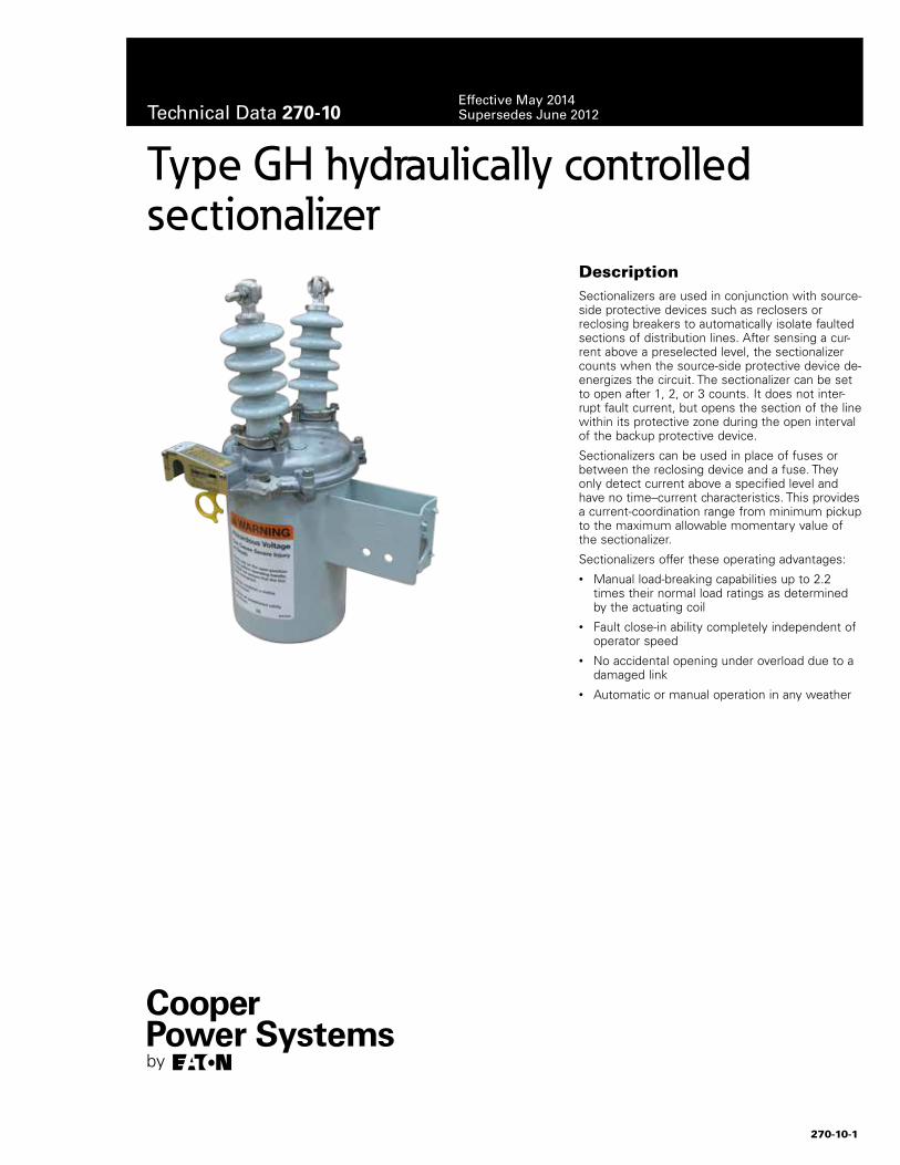
DescriptionSectionalizers are used in conjunction with source-side protective devices such as reclosers or reclosing breakers to automatically isolate faulted sections of distribution lines. After sensing a cur-rent above a preselected level, the sectionalizer counts when the source-side protective device de-energizes the circuit. The sectionalizer can be set to open after 1, 2, or 3 counts. It does not inter-rupt fault current, but opens the section of the line within its protective zone during the open interval of the backup protective device.
Sectionalizers can be used in place of fuses or between the reclosing device and a fuse. They only detect current above a specified level and have no time–current characteristics. This provides a current-coordination range from minimum pickup to the maximum allowable momentary value of the sectionalizer.
Sectionalizers offer these operating advantages: • Manual load-breaking capabilities up to 2.2
times their normal load ratings as determined by the actuating coil
• Fault close-in ability completely independent of operator speed
• No accidental opening under overload due to a damaged link
• Automatic or manual operation in any weather
Type GH hydraulically controlled sectionalizer
270-10-1
Technical Data 270-10Effective May 2014Supersedes June 2012
Ratings and characteristicsType GH single-phase hydraulically controlled sectionalizer can be applied to distribution systems within the ratings shown in Table 1.
A simple internal mechanism operates the sectionalizer. The mechanism incorporates a series-connected actuating coil, a plunger, and a trip piston to count and trip. The sectionalizer opens automatically but must be closed manually with the yellow operating handle under the sleet hood. The sectionalizer can also be tripped manually with the operating handle.
Operation
A sectionalizer is a self-contained circuit-opening device. It automati-cally opens its contacts after a backup recloser or circuit breaker de-energizes the circuit. Because a sectionalizer is not designed to interrupt fault current, it is always used in series with a backup fault-interrupting device.
A sectionalizer has no time–current characteristics, making it easily applicable to both new and existing coordination schemes. Figure 1 details the internal parts of the Type GH sectionalizer.
Surge protection
Sectionalizers operate best when protected with surge arresters. On line applications, arrester protection is recommended on both sides of the sectionalizer. If protection is to be provided on one side only, install the arrester on the source side. Eaton's Cooper Power Systems distribution-class arresters provide excellent protection; see Catalog 235-99, UltraSIL™ Polymer-Housed Evolution™ Surge Arresters.
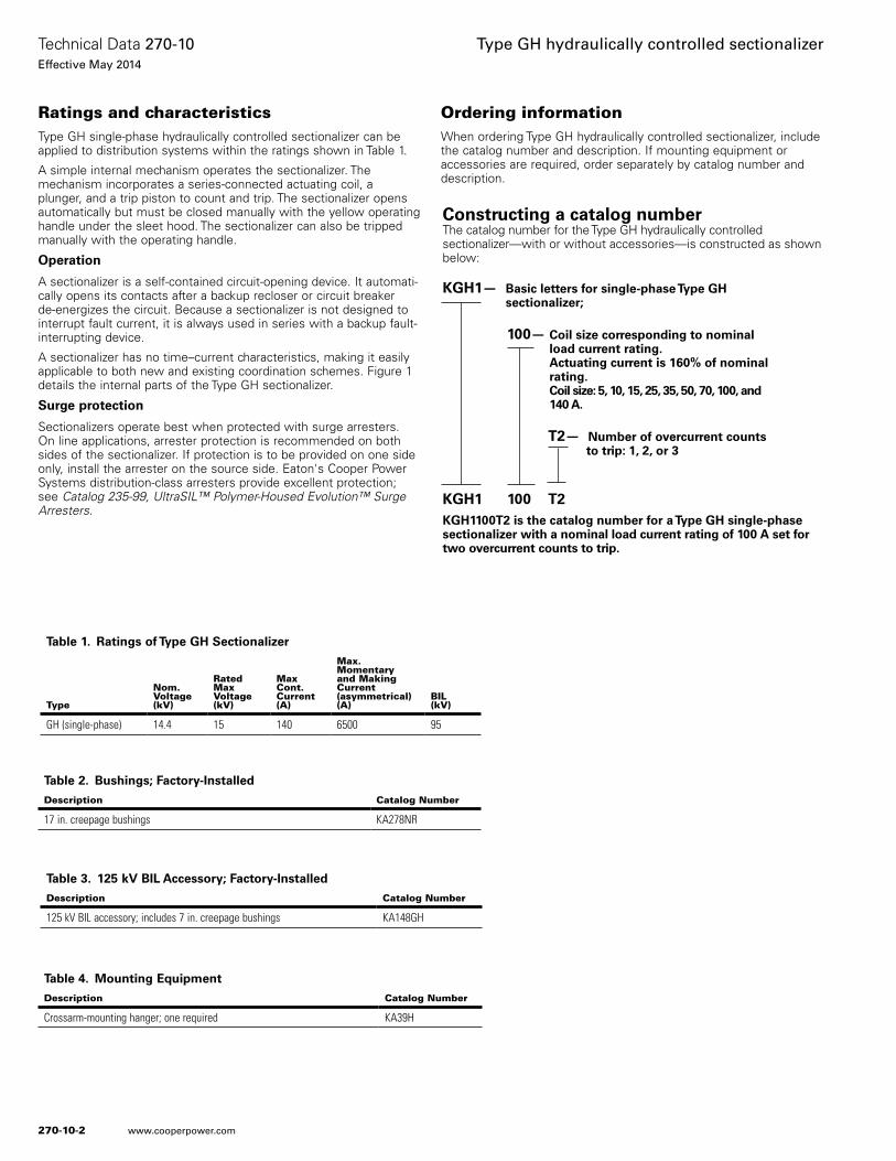
Ordering informationWhen ordering Type GH hydraulically controlled sectionalizer, include the catalog number and description. If mounting equipment or accessories are required, order separately by catalog number and description.
Constructing a catalog number The catalog number for the Type GH hydraulically controlled sectionalizer—with or without accessories—is constructed as shown below:
KGH1— Basic letters for single-phase Type GH sectionalizer;
100— Coil size corresponding to nominal load current rating. Actuating current is 160% of nominal rating. Coil size: 5, 10, 15, 25, 35, 50, 70, 100, and 140 A. T2— Number of overcurrent counts to trip: 1, 2, or 3
KGH1 100 T2KGH1100T2 is the catalog number for a Type GH single-phase sectionalizer with a nominal load current rating of 100 A set for two overcurrent counts to trip.
Table 2. Bushings; Factory-Installed
Description Catalog Number
17 in. creepage bushings KA278NR
Table 3. 125 kV BIL Accessory; Factory-Installed
Description Catalog Number
125 kV BIL accessory; includes 7 in. creepage bushings KA148GH
Table 4. Mounting Equipment
Description Catalog Number
Crossarm-mounting hanger; one required KA39H
Table 1. Ratings of Type GH Sectionalizer
Type
Nom.Voltage(kV)
RatedMaxVoltage(kV)
MaxCont.Current(A)
Max.Momentaryand MakingCurrent(asymmetrical) (A)
BIL(kV)
GH (single-phase) 14.4 15 140 6500 95
270-10-2
Technical Data 270-10Effective May 2014
Type GH hydraulically controlled sectionalizer
www.cooperpower.com
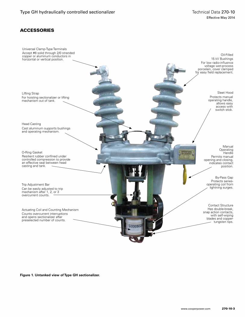
ACCESSORIES
Figure 1. Untanked view of Type GH sectionalizer.
Accept #8 solid through 2/0 stranded copper or aluminum conductors in horizontal or vertical position.
For low radio-influence voltage wet-process
porcelain, cover clamped for easy field replacement.
Resilient rubber confined under controlled compression to provide an effective seal between head casting and tank.
Cast aluminum supports bushings and operating mechanism.
For hoisting sectionalizer or lifting mechanism out of tank.
Can be easily adjusted to trip mechanism after 1, 2, or 3 overcurrent counts.
Permits manual opening and closing,
indicates contact position.
Has double-break, snap action contacts,
with self-wiping blades and copper-
tungsten tips.
Protects manual operating handle,
allows easy access with switch stick.
Universal Clamp-Type Terminals
Lifting Strap
Manual Operating
Handle
Trip Adjustment Bar
Head Casting
O-Ring Gasket
Oil-Filled 15 kV Bushings
Sleet Hood
Counts overcurrent interruptions and opens sectionalizer after preselected number of counts.
Actuating Coil and Counting MechanismContact Structure
Protects series-operating coil from
lightning surges.
By-Pass Gap
270-10-3
Technical Data 270-10Effective May 2014
Type GH hydraulically controlled sectionalizer
www.cooperpower.com
Sectionalizer operationA sectionalizer senses overcurrent interruptions and opens after 1, 2, or 3 such interruptions occur. It does this in two steps:
1. When the sectionalizer senses a current above its actuating level, it arms (prepares to count). The count occurs when current through the sectionalizer is interrupted or falls below a certain value.
2. If the predetermined number of counts are registered within a definite time period, the sectionalizer opens when the backup device has interrupted current flow to the system.
Example
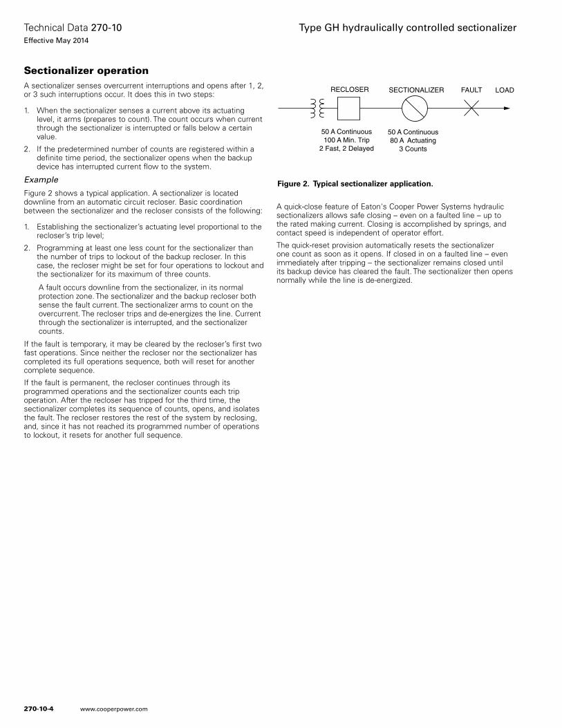
Figure 2 shows a typical application. A sectionalizer is located downline from an automatic circuit recloser. Basic coordination between the sectionalizer and the recloser consists of the following:
1. Establishing the sectionalizer’s actuating level proportional to the recloser’s trip level;
2. Programming at least one less count for the sectionalizer than the number of trips to lockout of the backup recloser. In this case, the recloser might be set for four operations to lockout and the sectionalizer for its maximum of three counts.
A fault occurs downline from the sectionalizer, in its normal protection zone. The sectionalizer and the backup recloser both sense the fault current. The sectionalizer arms to count on the overcurrent. The recloser trips and de-energizes the line. Current through the sectionalizer is interrupted, and the sectionalizer counts.
If the fault is temporary, it may be cleared by the recloser’s first two fast operations. Since neither the recloser nor the sectionalizer has completed its full operations sequence, both will reset for another complete sequence.
If the fault is permanent, the recloser continues through its programmed operations and the sectionalizer counts each trip operation. After the recloser has tripped for the third time, the sectionalizer completes its sequence of counts, opens, and isolates the fault. The recloser restores the rest of the system by reclosing, and, since it has not reached its programmed number of operations to lockout, it resets for another full sequence.
A quick-close feature of Eaton's Cooper Power Systems hydraulic sectionalizers allows safe closing – even on a faulted line – up to the rated making current. Closing is accomplished by springs, and contact speed is independent of operator effort.
The quick-reset provision automatically resets the sectionalizer one count as soon as it opens. If closed in on a faulted line – even immediately after tripping – the sectionalizer remains closed until its backup device has cleared the fault. The sectionalizer then opens normally while the line is de-energized.
SECTIONALIZERRECLOSER FAULT
50 A Continuous80 A Actuating
3 Counts
50 A Continuous100 A Min. Trip
2 Fast, 2 Delayed
LOAD
Figure 2. Typical sectionalizer application.
270-10-4
Technical Data 270-10Effective May 2014
Type GH hydraulically controlled sectionalizer
www.cooperpower.com
Counting mechanism operation
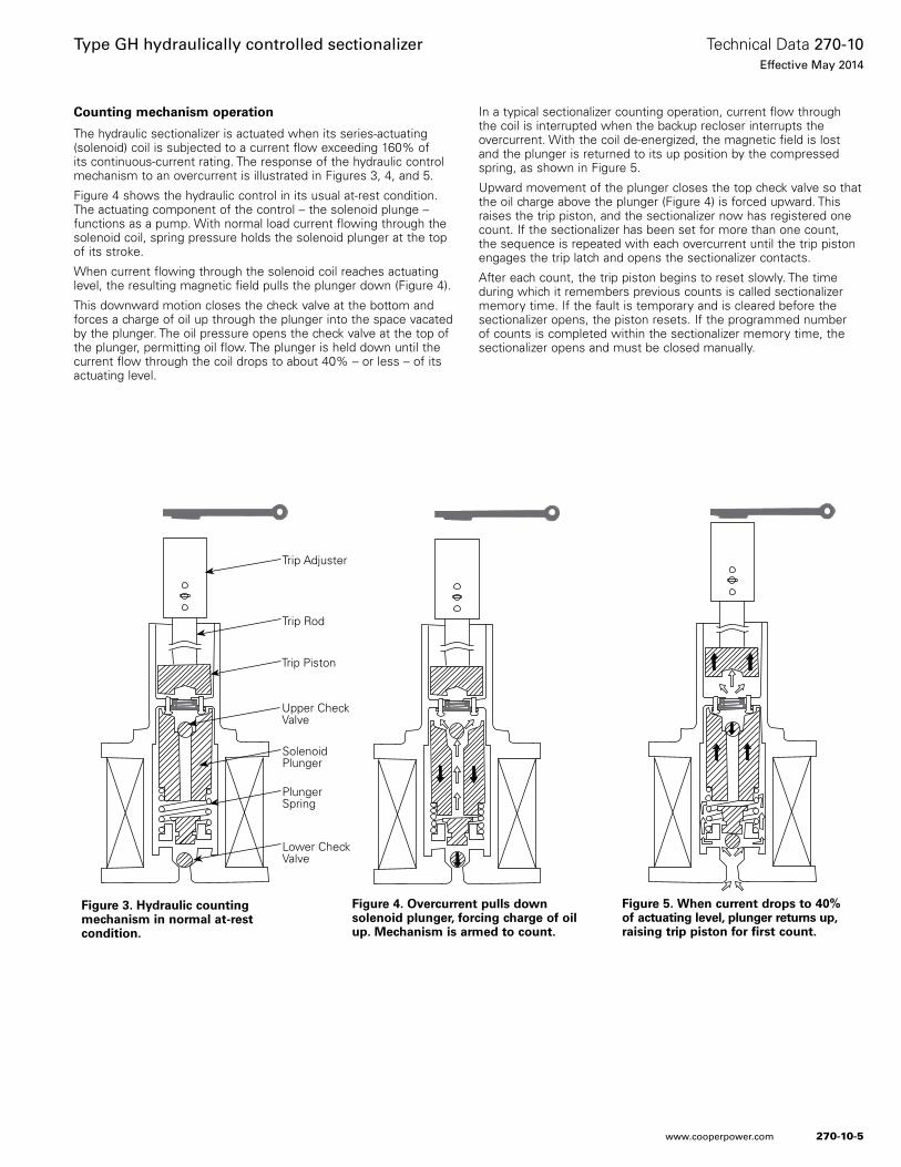
The hydraulic sectionalizer is actuated when its series-actuating (solenoid) coil is subjected to a current flow exceeding 160% of its continuous-current rating. The response of the hydraulic control mechanism to an overcurrent is illustrated in Figures 3, 4, and 5.
Figure 4 shows the hydraulic control in its usual at-rest condition. The actuating component of the control – the solenoid plunge – functions as a pump. With normal load current flowing through the solenoid coil, spring pressure holds the solenoid plunger at the top of its stroke.
When current flowing through the solenoid coil reaches actuating level, the resulting magnetic field pulls the plunger down (Figure 4).
This downward motion closes the check valve at the bottom and forces a charge of oil up through the plunger into the space vacated by the plunger. The oil pressure opens the check valve at the top of the plunger, permitting oil flow. The plunger is held down until the current flow through the coil drops to about 40% – or less – of its actuating level.
In a typical sectionalizer counting operation, current flow through the coil is interrupted when the backup recloser interrupts the overcurrent. With the coil de-energized, the magnetic field is lost and the plunger is returned to its up position by the compressed spring, as shown in Figure 5.
Upward movement of the plunger closes the top check valve so that the oil charge above the plunger (Figure 4) is forced upward. This raises the trip piston, and the sectionalizer now has registered one count. If the sectionalizer has been set for more than one count, the sequence is repeated with each overcurrent until the trip piston engages the trip latch and opens the sectionalizer contacts.
After each count, the trip piston begins to reset slowly. The time during which it remembers previous counts is called sectionalizer memory time. If the fault is temporary and is cleared before the sectionalizer opens, the piston resets. If the programmed number of counts is completed within the sectionalizer memory time, the sectionalizer opens and must be closed manually.
Figure 4. Overcurrent pulls down solenoid plunger, forcing charge of oil up. Mechanism is armed to count.
Figure 5. When current drops to 40% of actuating level, plunger returns up, raising trip piston for first count.
Figure 3. Hydraulic counting mechanism in normal at-rest condition.
Upper Check Valve
Trip Adjuster
Trip Rod
Trip Piston
Solenoid Plunger
Plunger Spring
Lower Check Valve
270-10-5
Technical Data 270-10Effective May 2014
Type GH hydraulically controlled sectionalizer
www.cooperpower.com
Application recommendationsThe following basic coordination principles should be observed in the application of hydraulic sectionalizers:
1. The sectionalizer’s minimum-actuating-current rating should be approximately 80% of the minimum-trip rating of the source-side protective device.
Note: This requirement is usually satisfied by pairing the sectionalizer with an equally continuous-current-rated hydraulic recloser The continuous-current and minimum-actuating-current ratings of the sectionalizer correspond to – and are compatible with – hydraulic recloser ratings.
2. The sectionalizer should be set to open one count less than the total operations to lockout of the backup device.
Note: This rule need not apply when several sectionalizers are in series; successive units may be set for 1, 2, or 3 counts less than backup recloser operations.
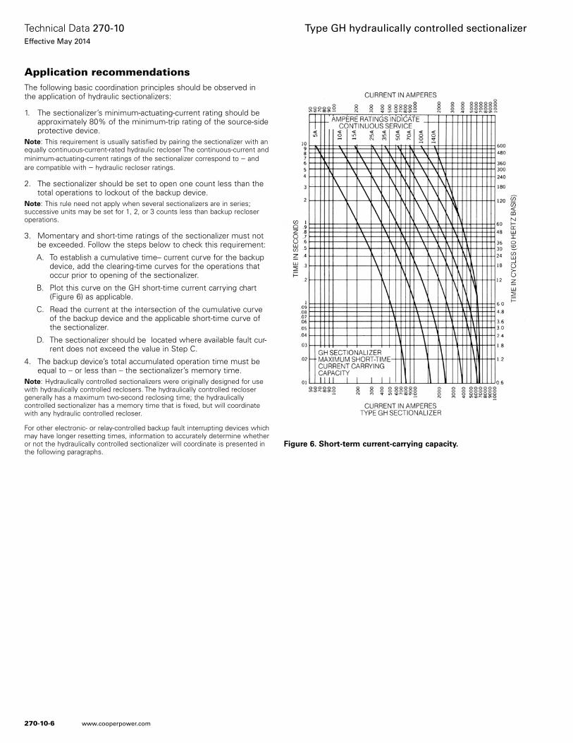
3. Momentary and short-time ratings of the sectionalizer must not be exceeded. Follow the steps below to check this requirement:
A. To establish a cumulative time– current curve for the backup device, add the clearing-time curves for the operations that occur prior to opening of the sectionalizer.
B. Plot this curve on the GH short-time current carrying chart (Figure 6) as applicable.
C. Read the current at the intersection of the cumulative curve of the backup device and the applicable short-time curve of the sectionalizer.
D. The sectionalizer should be located where available fault cur-rent does not exceed the value in Step C.
4. The backup device’s total accumulated operation time must be equal to – or less than – the sectionalizer’s memory time.
Note: Hydraulically controlled sectionalizers were originally designed for use with hydraulically controlled reclosers. The hydraulically controlled recloser generally has a maximum two-second reclosing time; the hydraulically controlled sectionalizer has a memory time that is fixed, but will coordinate with any hydraulic controlled recloser.
For other electronic- or relay-controlled backup fault interrupting devices which may have longer resetting times, information to accurately determine whether or not the hydraulically controlled sectionalizer will coordinate is presented in the following paragraphs.
Figure 6. Short-term current-carrying capacity.
270-10-6
Technical Data 270-10Effective May 2014
Type GH hydraulically controlled sectionalizer
www.cooperpower.com
Coordination of sectionalizer with backup protective devices Coordination of Types GH hydraulically controlled sectionalizer with backup reclosers or breakers is a function of the sectionalizer’s maximum oil temperature and the backup device’s operating sequence.
Sectionalizer oil temperature
Sectionalizer memory time depends upon the resetting of the hydraulic counting mechanism. Thus, memory time is a function of oil viscosity which in turn depends upon oil temperature.
The temperature rise of the oil due to current flow through the coil, contacts and lead wires at various load-current levels is shown in Table 5.
Assuming a period of load-current flow prior to sectionalizer operation, add the temperature rise to the sectionalizer ambient temperature to determine the approximate maximum oil temperature.
Operating sequence of backup device
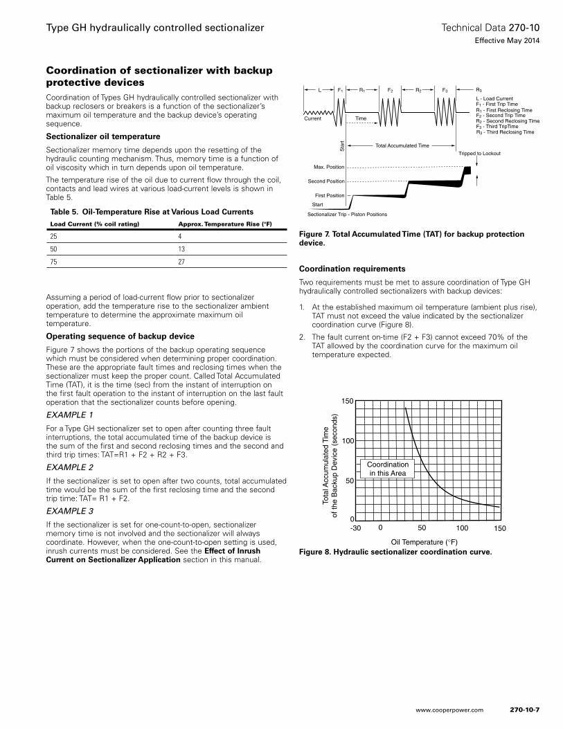
Figure 7 shows the portions of the backup operating sequence which must be considered when determining proper coordination. These are the appropriate fault times and reclosing times when the sectionalizer must keep the proper count. Called Total Accumulated Time (TAT), it is the time (sec) from the instant of interruption on the first fault operation to the instant of interruption on the last fault operation that the sectionalizer counts before opening.
EXAMPLE 1
For a Type GH sectionalizer set to open after counting three fault interruptions, the total accumulated time of the backup device is the sum of the first and second reclosing times and the second and third trip times: TAT=R1 + F2 + R2 + F3.
EXAMPLE 2
If the sectionalizer is set to open after two counts, total accumulated time would be the sum of the first reclosing time and the second trip time: TAT= R1 + F2.
EXAMPLE 3
If the sectionalizer is set for one-count-to-open, sectionalizer memory time is not involved and the sectionalizer will always coordinate. However, when the one-count-to-open setting is used, inrush currents must be considered. See the Effect of Inrush Current on Sectionalizer Application section in this manual.
Coordination requirements
Two requirements must be met to assure coordination of Type GH hydraulically controlled sectionalizers with backup devices:
1. At the established maximum oil temperature (ambient plus rise), TAT must not exceed the value indicated by the sectionalizer coordination curve (Figure 8).
2. The fault current on-time (F2 + F3) cannot exceed 70% of the TAT allowed by the coordination curve for the maximum oil temperature expected.
Time
Start
First Position
Second Position
Sta
rt
Tripped to Lockout
Total Accumulated Time
Max. Position
Current
L - Load Current
R3L F1 R1 F2 R2 F3
Sectionalizer Trip - Piston Positions
R3 - Third Reclosing Time
F1 - First Trip Time
F2 - Second Trip Time
F3 - Third TripTime
R1 - First Reclosing Time
R2 - Second Reclosing Time
Figure 7. Total Accumulated Time (TAT) for backup protection device.
Coordinationin this Area
0
Oil Temperature (°F)
Tota
l Acc
umul
ated
Tim
eof
the
Bac
kup
Dev
ice
(sec
onds
)
150
100
50
-300
15010050
Figure 8. Hydraulic sectionalizer coordination curve.
Table 5. Oil-Temperature Rise at Various Load Currents
Load Current (% coil rating) Approx. Temperature Rise (°F)
25 4
50 13
75 27
270-10-7
Technical Data 270-10Effective May 2014
Type GH hydraulically controlled sectionalizer
www.cooperpower.com
Example 1
Conditions:
Max. ambient temperature 85 °F
Sectionalizer coil size 100 A
Normal load current 50 A
Backup OCR set for 1 fast, 3 delayed operations
Sectionalizer set for 3 counts to open
Maximum oil temperature: 85 + 13 = 98 °F
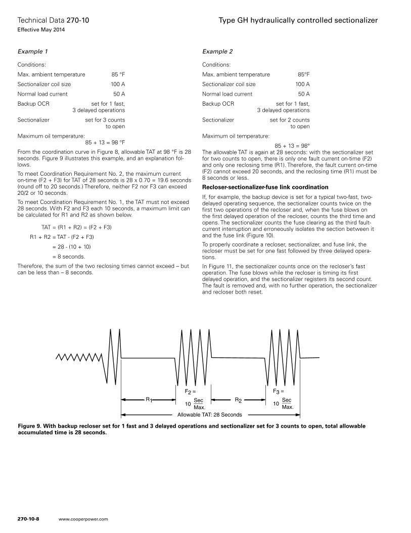
From the coordination curve in Figure 8, allowable TAT at 98 °F is 28 seconds. Figure 9 illustrates this example, and an explanation fol-lows.
To meet Coordination Requirement No. 2, the maximum current on-time (F2 + F3) for TAT of 28 seconds is 28 x 0.70 = 19.6 seconds (round off to 20 seconds.) Therefore, neither F2 nor F3 can exceed 20/2 or 10 seconds.
To meet Coordination Requirement No. 1, the TAT must not exceed 28 seconds. With F2 and F3 each 10 seconds, a maximum limit can be calculated for R1 and R2 as shown below.
TAT = (R1 + R2) = (F2 + F3)
R1 + R2 = TAT - (F2 + F3)
= 28 - (10 + 10)
= 8 seconds.
Therefore, the sum of the two reclosing times cannot exceed – but can be less than – 8 seconds.
Example 2
Conditions:
Max. ambient temperature 85°F
Sectionalizer coil size 100 A
Normal load current 50 A
Backup OCR set for 1 fast, 3 delayed operations
Sectionalizer set for 2 counts to open
Maximum oil temperature:
85 + 13 = 98°The allowable TAT is again at 28 seconds: with the sectionalizer set for two counts to open, there is only one fault current on-time (F2) and only one reclosing time (R1). Therefore, the fault current on-time (F2) cannot exceed 20 seconds, and the reclosing time (R1) must be 8 seconds or less.
Recloser-sectionalizer-fuse link coordination
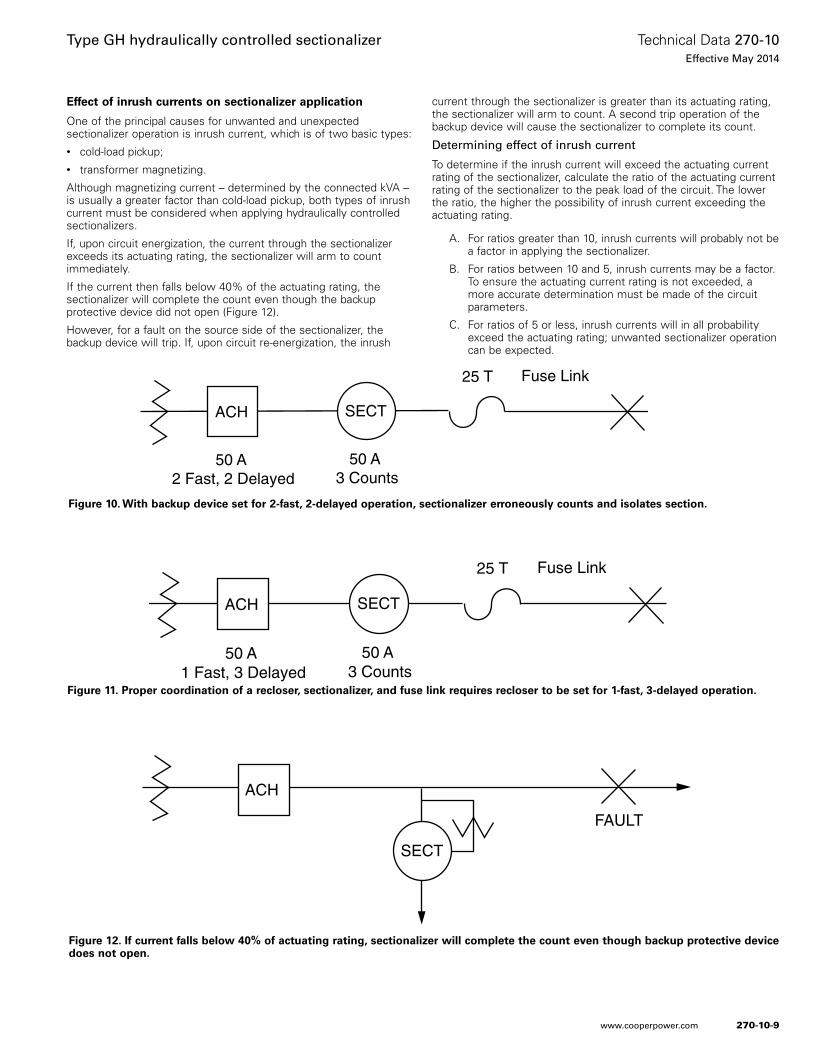
If, for example, the backup device is set for a typical two-fast, two-delayed operating sequence, the sectionalizer counts twice on the first two operations of the recloser and, when the fuse blows on the first delayed operation of the recloser, counts the third time and opens. The sectionalizer counts the fuse clearing as the third fault-current interruption and erroneously isolates the section between it and the fuse link (Figure 10).
To properly coordinate a recloser, sectionalizer, and fuse link, the recloser must be set for one fast followed by three delayed opera-tions.
In Figure 11, the sectionalizer counts once on the recloser’s fast operation. The fuse blows while the recloser is timing its first delayed operation, and the sectionalizer registers its second count. The fault is removed and, with no further operation, the sectionalizer and recloser both reset.
Allowable TAT: 28 Seconds
R2
F2 = Sec10 ___ Max.
R1
F3 = Sec10 ___ Max.
Figure 9. With backup recloser set for 1 fast and 3 delayed operations and sectionalizer set for 3 counts to open, total allowable accumulated time is 28 seconds.
270-10-8
Technical Data 270-10Effective May 2014
Type GH hydraulically controlled sectionalizer
www.cooperpower.com
Effect of inrush currents on sectionalizer application
One of the principal causes for unwanted and unexpected sectionalizer operation is inrush current, which is of two basic types: • cold-load pickup;• transformer magnetizing.
Although magnetizing current – determined by the connected kVA – is usually a greater factor than cold-load pickup, both types of inrush current must be considered when applying hydraulically controlled sectionalizers.
If, upon circuit energization, the current through the sectionalizer exceeds its actuating rating, the sectionalizer will arm to count immediately.
If the current then falls below 40% of the actuating rating, the sectionalizer will complete the count even though the backup protective device did not open (Figure 12).
However, for a fault on the source side of the sectionalizer, the backup device will trip. If, upon circuit re-energization, the inrush
current through the sectionalizer is greater than its actuating rating, the sectionalizer will arm to count. A second trip operation of the backup device will cause the sectionalizer to complete its count.
Determining effect of inrush current
To determine if the inrush current will exceed the actuating current rating of the sectionalizer, calculate the ratio of the actuating current rating of the sectionalizer to the peak load of the circuit. The lower the ratio, the higher the possibility of inrush current exceeding the actuating rating.
A. For ratios greater than 10, inrush currents will probably not be a factor in applying the sectionalizer.
B. For ratios between 10 and 5, inrush currents may be a factor. To ensure the actuating current rating is not exceeded, a more accurate determination must be made of the circuit parameters.
C. For ratios of 5 or less, inrush currents will in all probability exceed the actuating rating; unwanted sectionalizer operation can be expected.
SECT
ACH
FAULT
Figure 12. If current falls below 40% of actuating rating, sectionalizer will complete the count even though backup protective device does not open.
SECTACH
50 A 2 Fast, 2 Delayed
50 A 3 Counts
25 T Fuse Link
Figure 10. With backup device set for 2-fast, 2-delayed operation, sectionalizer erroneously counts and isolates section.
SECTACH
50 A 1 Fast, 3 Delayed
50 A 3 Counts
25 T Fuse Link
Figure 11. Proper coordination of a recloser, sectionalizer, and fuse link requires recloser to be set for 1-fast, 3-delayed operation.
270-10-9
Technical Data 270-10Effective May 2014
Type GH hydraulically controlled sectionalizer
www.cooperpower.com

Ratings and specifications
Table 6. Voltage Ratings
Nominal system rated voltage (kV rms) 14.4
Rated max voltage (kV rms) 15.0
Rated impulse withstand voltage (BIL; kV crest) 95
60 Hz insulation level withstand
dry, 1 min. (kV rms) 35
wet, 10 sec. (kV rms) 30
Creepage distance, standard bushings (in.) 9-3/4
Table 7. Current Ratings
Continuous Current(A)
InterruptingLoad-BreakCurrent (A)
ActuatingCurrent(A)
Short-Time Current Ratings
Momentary and Making(asym A)
1 Second (sym A)
10 Second(sym A)
5 308 8 800 200 60
10 308 16 1600 400 125
15 308 24 2400 600 190
25 308 40 4000 1000 325
35 308 56 6000 1500 450
50 308 80 6500 2000 650
70 308 112 6500 3000 900
100 308 160 6500 4000 1250
140 308 224 6500 4000 1800
Table 8. Weight and Oil Capacity
Weight (lb) Oil Capacity
Dry With Oil (gal)
20 31-1/2 1-1/2
270-10-10
Technical Data 270-10Effective May 2014
Type GH hydraulically controlled sectionalizer
www.cooperpower.com
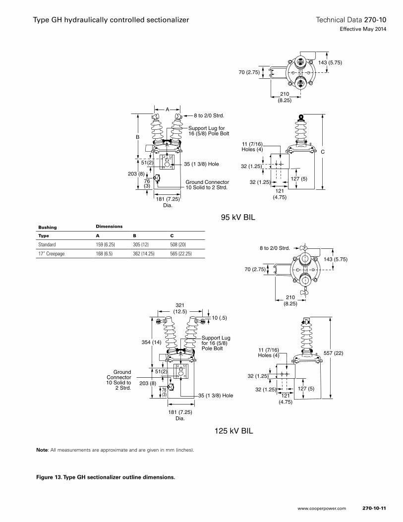
Figure 13. Type GH sectionalizer outline dimensions.
C
203 (8)
B
A8 to 2/0 Strd.
181 (7.25)Dia.
51(2)
76(3)
Support Lug for16 (5/8) Pole Bolt
95 kV BIL
Ground Connector10 Solid to 2 Strd.
11 (7/16)Holes (4)
321(12.5)
354 (14)
127 (5)121
(4.75)
70 (2.75)
210(8.25)
8 to 2/0 Strd.
GroundConnector10 Solid to
2 Strd.
557 (22)
125 kV BIL
32 (1.25)
Support Lugfor 16 (5/8)Pole Bolt
143 (5.75)
32 (1.25)
181 (7.25)Dia.
76(3)
203 (8)
51(2)
121(4.75)
32 (1.25)
32 (1.25)
127 (5)
143 (5.75)
70 (2.75)
210(8.25)
11 (7/16)Holes (4)
35 (1 3/8) Hole
10 (.5)
35 (1 3/8) Hole
Note: All measurements are approximate and are given in mm (inches).
Bushing Dimensions
Type A B C
Standard 159 (6.25) 305 (12) 508 (20)
17” Creepage 168 (6.5) 362 (14.25) 565 (22.25)
270-10-11
Technical Data 270-10Effective May 2014
Type GH hydraulically controlled sectionalizer
www.cooperpower.com
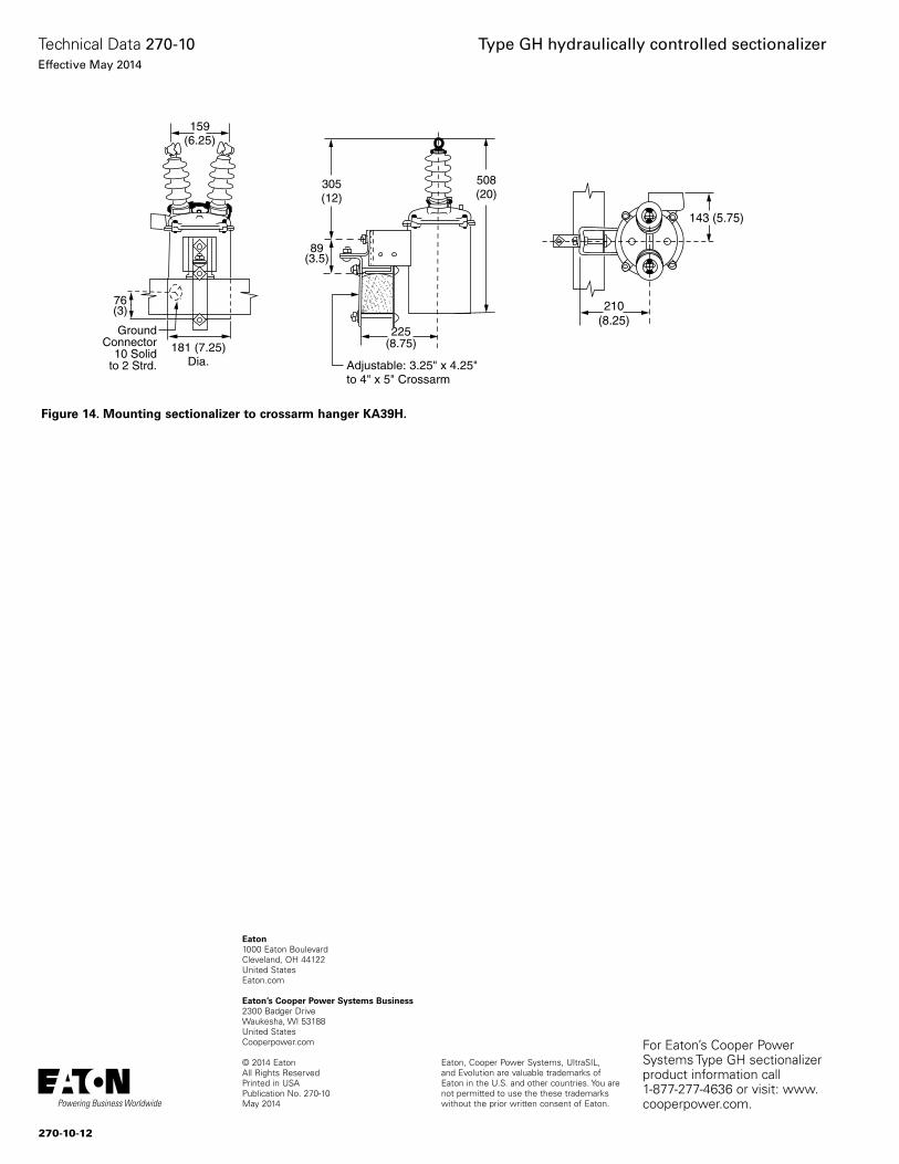
Figure 14. Mounting sectionalizer to crossarm hanger KA39H.
159(6.25)
181 (7.25)Dia.
76(3)
GroundConnector
10 Solidto 2 Strd.
305(12)
89(3.5)
225(8.75)
Adjustable: 3.25" x 4.25"to 4" x 5" Crossarm
508(20)
143 (5.75)
210(8.25)
Eaton, Cooper Power Systems, UltraSIL, and Evolution are valuable trademarks of Eaton in the U.S. and other countries. You are not permitted to use the these trademarks without the prior written consent of Eaton.
Type GH hydraulically controlled sectionalizer
Eaton1000 Eaton BoulevardCleveland, OH 44122United StatesEaton.com
Eaton’s Cooper Power Systems Business2300 Badger DriveWaukesha, WI 53188United StatesCooperpower.com
© 2014 EatonAll Rights ReservedPrinted in USAPublication No. 270-10May 2014
Technical Data 270-10Effective May 2014
For Eaton’s Cooper Power Systems Type GH sectionalizer product information call 1-877-277-4636 or visit: www.cooperpower.com.
270-10-12
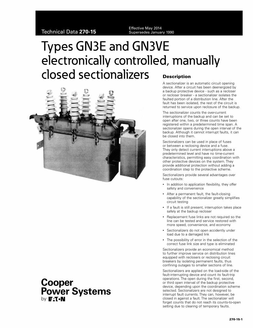
DescriptionA sectionalizer is an automatic circuit opening device. After a circuit has been deenergized by a backup protective device - such as a recloser or recloser breaker - a sectionalizer isolates the faulted portion of a distribution line. After the fault has been isolated, the rest of the circuit is returned to service upon reclosure of the backup.
The sectionalizer counts the over-current interruptions of the backup and can be set to open after one, two, or three counts have been registered within a predetermined time span. A sectionalizer opens during the open interval of the backup. Although it cannot interrupt faults, it can be closed into them.
Sectionalizers can be used in place of fuses or between a reclosing device and a fuse. They only detect current interruptions above a predetermined level and have no time-current characteristics, permitting easy coordination with other protective devices on the system. They provide additional protection without adding a coordination step to the protective scheme.
Sectionalizers provide several advantages over fuse cutouts:• In addition to application flexibility, they offer
safety and convenience• After a permanent fault, the fault-closing
capability of the sectionalizer greatly simplifies circuit testing
• If a fault is still present, interruption takes place safely at the backup recloser
• Replacement fuse links are not required so the line can be tested and service restored with more speed, convenience, and economy
• Sectionalizers do not open accidently under load due to a damaged link
• The possibility of error in the selection of the correct fuse link size and type is eliminated
Sectionalizers provide an economical method to further improve service on distribution lines equipped with reclosers or reclosing circuit breakers by isolating permanent faults, thus confining outages to smaller sections of line.
Sectionalizers are applied on the load-side of the fault-interrupting device and count its fault-trip operations. The open during the first, second, or third open interval of the backup protective device, depending upon the coordination scheme selected. Sectionalizers are not designed to interrupt fault currents. They can, however, be closed in against a fault. The sectionalizer will forget counts that do not reach its counts-to-open setting due to clearing of temporary faults.
Types GN3E and GN3VE electronically controlled, manually closed sectionalizers
270-15-1
Technical Data 270-15Effective May 2014Supersedes January 1990
When properly applied, a sectionalizer will respond to downline fault currents that ate interrupted by its backup protective device. However, as with any other protective device, system conditions may product unexpected and unwanted sectionalizer operation.
Overcurrents interrupted by a downline protective device are one cause for these occurrences; inrush current is another. Count-restraint and inrush current restraint features are built into the electronic control to block the sectionalizer's response to these system conditions.
Summary of ratingsThe solid-state electronic control used in the Type GN3E and GN3VE three-phase sectionalizers provides accurate and reliable operation down to 16 amps on phase-fault and 3.5 amps on ground- (earth-) fault detection. Operation is unaffected over a wide range of ambient temperatures. Basic ratings are shown in Table 1.
The sectionalizer is self-contained. Current transformers- internally mounted on the bushings - provide power to operate the electronic control and the trip mechanism. Since these CTs obtain power from the line, no external source of auxiliary power is required.
Operation
The Type GN3E or GN3VE sectionalizer is a three-phase device that opens all three phases simultaneously for either a phase or ground fault or when used as a loadbreak switch. Three sets of oil-insulated contacts are connected by bellcranks to a common operating mechanism. A low-energy tripping mechanism-operated by the electronic control - initiates opening. Opening energy is provided by springs, charged when the sectionalizer is manually closed.
The sectionalizer senses overcurrent interruptions and opens after one, two, or three such interruptions have occurred. When a current above the reset actuating level of the sectionalizer is interrupted by a backup protective device, a count pulse is generated and registered in the electronic control. If the preset number of counts is registered within one minute, the sectionalizer will open during the open inter-
val of the backup device (when no current is flowing in the circuit).
The sectionalizer is completely self-contained. Power to operate the control and low-energy tripper is obtained from the line through bushing current transformers (mounted under the head) which sense the phase- and ground-fault currents. No auxiliary power supply is required.
The solid-state electronic control provides the operating logic for automatic opening. Closing is accomplished by manually closing the yellow operating handle under the sleet hood. The sectionalizer may also be manually opened with this handle which also provides a positive visual indication of contact position.
Surge protection
Sectionalizers operate best when protected with surge arresters. On line applications, arrester protection is recommended on both sides of the sectionalizer. If protection is to be provided on one side only, install the arrester on the source side. Eaton's Cooper Power Systems distribution-class arresters provide excellent protection; see Catalog 235-99, UltraSIL™ Polymer-Housed Evolution™ Surge Arresters.
Ordering informationWhen ordering a Type GN3E or GN3VE sectionalizer, include catalog number and description of basic sectionalizer and the phase and ground minimum-actuating-current plug-in resistors. A set (one each) of the phase and ground minimum-actuating-current plug-in resistors is included in the price of the basic sectionalizer. Also specify the operating settings for the inrush-current restraint. If accessories and/or mounting equipment are required, specify by catalog number and description.
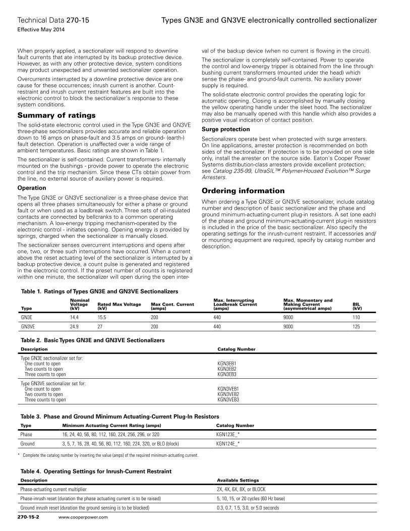
Table 2. Basic Types GN3E and GN3VE Sectionalizers
Description Catalog Number
Type GN3E sectionalizer set for: One count to open Two counts to open Three counts to open
KGN3EB1KGN3EB2KGN3EB3
Type GN3VE sectionalizer set for: One count to open Two counts to open Three counts to open
KGN3VEB1KGN3VEB2KGN3VEB3
Table 3. Phase and Ground Minimum Actuating-Current Plug-In Resistors
Type Minimum Actuating Current Rating (amps) Catalog Number
Phase 16, 24, 40, 56, 80, 112, 160, 224, 256, 296, or 320 KGN123E_*
Ground 3, 5, 7, 16, 28, 40, 56, 80, 112, 160, 224, 320, or BLO (block) KGN124E_*
Table 4. Operating Settings for Inrush-Current Restraint
Description Available Settings
Phase-actuating current multiplier 2X, 4X, 6X, 8X, or BLOCK
Phase-inrush reset (duration the phase actuating current is to be raised) 5, 10, 15, or 20 cycles (60 Hz base)
Ground inrush reset (duration the ground sensing is to be blocked) 0.3, 0.7, 1.5, 3.0, or 5.0 seconds
Table 1. Ratings of Types GN3E and GN3VE Sectionalizers
Type
NominalVoltage(kV)
Rated Max Voltage(kV)
Max Cont. Current(amps)
Max. Interrupting Loadbreak Current(amps)
Max. Momentary and Making Current (asymmetrical amps)
BIL(kV)
GN3E 14.4 15.5 200 440 9000 110
GN3VE 24.9 27 200 440 9000 125
* Complete the catalog number by inserting the value (amps) of the required minimum-actuating current.
270-15-2
Technical Data 270-15Effective May 2014
Types GN3E and GN3VE electronically controlled sectionalizer
www.cooperpower.com
Accessories and mounting equipment
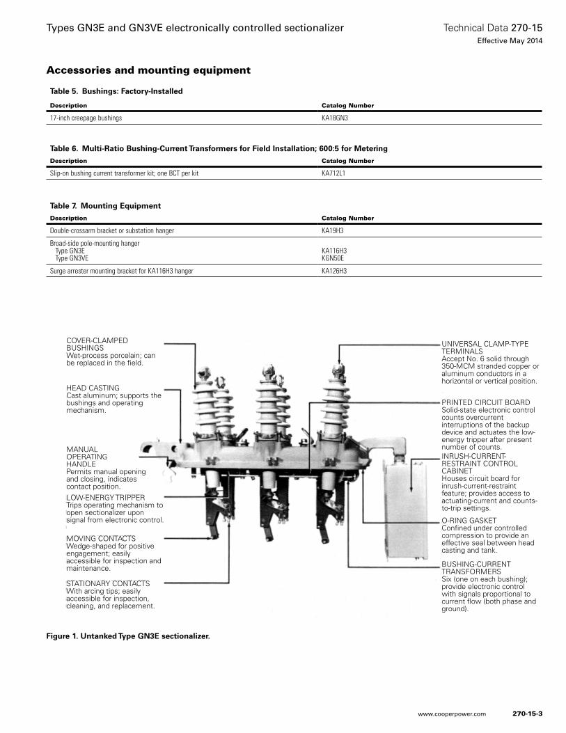
Figure 1. Untanked Type GN3E sectionalizer.
UNIVERSAL CLAMP-TYPE TERMINALSAccept No. 6 solid through 350-MCM stranded copper or aluminum conductors in a horizontal or vertical position.
PRINTED CIRCUIT BOARDSolid-state electronic control counts overcurrent interruptions of the backup device and actuates the low-energy tripper after present number of counts.INRUSH-CURRENT-RESTRAINT CONTROL CABINETHouses circuit board for inrush-current-restraint feature; provides access to actuating-current and counts-to-trip settings.
O-RING GASKETConfined under controlled compression to provide an effective seal between head casting and tank.
BUSHING-CURRENT TRANSFORMERSSix (one on each bushing); provide electronic control with signals proportional to current flow (both phase and ground).
COVER-CLAMPED BUSHINGSWet-process porcelain; can be replaced in the field.
HEAD CASTINGCast aluminum; supports the bushings and operating mechanism.
LOW-ENERGY TRIPPERTrips operating mechanism to open sectionalizer upon signal from electronic control.
MOVING CONTACTSWedge-shaped for positive engagement; easily accessible for inspection and maintenance.
STATIONARY CONTACTSWith arcing tips; easily accessible for inspection, cleaning, and replacement.
MANUAL OPERATING HANDLEPermits manual opening and closing, indicates contact position.
Table 5. Bushings: Factory-Installed
Description Catalog Number
17-inch creepage bushings KA18GN3
Table 6. Multi-Ratio Bushing-Current Transformers for Field Installation; 600:5 for Metering
Description Catalog Number
Slip-on bushing current transformer kit; one BCT per kit KA712L1
Table 7. Mounting Equipment
Description Catalog Number
Double-crossarm bracket or substation hanger KA19H3
Broad-side pole-mounting hanger Type GN3E Type GN3VE
KA116H3KGN50E
Surge arrester mounting bracket for KA116H3 hanger KA126H3
270-15-3
Technical Data 270-15Effective May 2014
Types GN3E and GN3VE electronically controlled sectionalizer
www.cooperpower.com
Electronic controlA functional block diagram of the electronic control circuity is shown in Figure 2.
Bushing current transformers (BCT) sense the current flowing through the sectionalizer. Three transformers connected in a wye (star) configuration sense phase current. Three additional BCTs, connected in parallel, sense the ground- (earth-) or zero-sequence current. By selecting the proper plug-in resistors, these signals can be rectified and adjusted to the desired minimum actuating-current level.
To generate and register a count pulse, a current above the preset minimum actuating level must be flowing through the sectionalizer (downline fault). This overcurrent must drop to zero (fault interrupted by the backup protective device). The pulse counter provides storage for up to three pulses. Depending upon the counts-to-open setting, the tripping circuit will turn on after one, two, or three count pulses have been registered. When turned on, the tripping circuit completes the discharge path for the trip-energy-storage capacitors through the coil of the low-energy tripper which, in turn, trips the sectionalizer mechanism to open the sectionalizer contacts.
The pulse counter has a 60-second memory for each count. Thus, the preset number of counts must be registered within one minute for the sectionalizer to open. The control will reset (completely forget the registered count pulses that do not reach the preset number) within seven (7) minutes.
Types GN3E and GN3VE electronic sectionalizers contain a count-restraint feature. This feature prevents the sectionalizer from counting fault currents interrupted by a downline protective device. The current restraint will block the generation of a count pulse as long as at least 3-1/2 amps of load current are flowing through the sectionalizer after the fault current disappears.
The sectionalizer is also equipped with an inrush-current restraint feature which distinguishes between inrush current and fault current by a logic circuit functionally diagrammed in Figure 3.
If an overcurrent is present through the sectionalizer when the backup protective device opens (current is interrupted), the overcurrent present upon reclosing is assumed to be fault current and the sectionalizer control operates in its normal manner. If, however, there is no overcurrent detected by the sectionalizer when the current is interrupted, the overcurrent present upon reclosing is assumed to be inrush current. To prevent the sectionalizer from counting this inrush current, the fault-level detector circuit is modified to raise the phase-actuating level by a multiple of 2X, 4X, 6X, or 8X the normal setting (or current detection can be blocked entirely) for a time (Y) of 5, 10, 15, or 20 cycles after current flow through the sectionalizer is restored. After this time, the sectionalizer control returns to normal operating settings. At the
same time, ground overcurrent detection is blocked entirely for a period (Z) of 0.3, 0.7, 1.5, 3, or 5 seconds after current flow through the sectionalizer is restored.
On multi-grounded-wye systems, the entire transient inrush of a particular phase could flow in the neutral. Typical settings for ground-fault sensing on these systems is one-half or less of phase-fault sensing. This could result in values at lease twice those necessary for phase magnitude and duration (X and Y). With the improved ground-inrush logic, ground sensing is simply blocked for the duration of the Z selected.
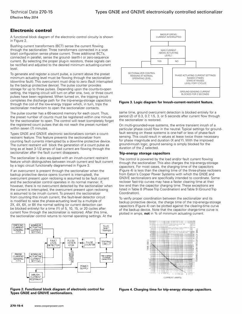
Trip-energy storage capacitors
The control is powered by the load and/or fault current flowing through the sectionalizer. This also charges the trip-energy-storage capacitors. For most cases, the charging time of the capacitors (Figure 4) is less than the clearing time of the three-phase reclosers from Eaton's Cooper Power Systems with which the GN3E and GN3VE sectionalizers are specifically intended to coordinate. Some recloser fast-trip curves may have a faster clearing time at their low end than the capacitor charging time. These exceptions are listed in Table 8 (Phase Trip Coordination) and Table 9 (Ground Trip Coordination).
To verify proper coordination between the sectionalizer and its backup protective device, the charge time of the trip-energy-storage capacitors (Figure 4) can be plotted against the clearing-time curve of the backup device. Note that the capacitor charge-time curve is plotted in amps, not in % of minimum actuating current.
Figure 2. Functional block diagram of electronic control for Types GN3E and GN3VE sectionalizers.
SECTIONALIZER CONTROLREMAINS AT NORMAL
OPERATING LEVEL
WAS CURRENTABOVE ACTUATING
LEVEL?
YES NO
BACKUP OPENS;CURRENT INTERRUPTED
PHASE ACTUATING CURRENT SETTINGSRAISED X TIMESSTAYS AT RAISED
LEVEL FOR Y CYCLES
GROUND-SENSING CURRENTBLOCKED FOR 2 SECONDS
Figure 3. Logic diagram for Inrush-current-restraint feature.
Figure 4. Charging time for trip-energy storage capacitors.
270-15-4
Technical Data 270-15Effective May 2014
Types GN3E and GN3VE electronically controlled sectionalizer
www.cooperpower.com
Count-restraint feature
The count-restraint feature blocks the sectionalizer from generating a count pulse as long as some load current flows through the sectionalizer. Thus, the sectionalizer does not count or operate when a load-side device interrupts the overcurrent.
Figure 5 show a typical application with the sectionalizer located between two reclosers.
For a fault (F1) beyond the load-side recloser (ACR2), only the load-side recloser operates. The sectionalizer does not generate a count because the load current through the sectionalizer is not interrupted. For a load-side fault (F2) interrupted by the souce-side recloser (ACR1), the sectionalizer counts the fault interruption since the load current through the sectionalizer is interrupted.
The count-restraint feature is designed to operate with a minimum of 3-1/2 amps load current through the sectionalizer. It is a standard feature of all GN3E and GN3VE electronically controlled sectionalizer.
Inrush-current restraint feature
One of the principal causes for unwanted sectionalizer operation is inrush current. If the backup device interrupts a fault on the down-line side of the sectionalizer, the sectionalizer will generate and reg-ister a count pulse in the normal manner. If the fault is interrupted by a downline protective device, the count-restraint feature will block the generation of a count pulse if at least 3-1/2 amps of uninter-rupted load current flows through the sectionalizer.
For a fault on the source-side of the sectionalizer (Figure 6), the backup device will trip and deenergize the circuit. However, if upon circuit renergization, the inrush current through the sectionalizer is greater than its minimum actuating current setting, a second trip operation of the backup device will defeat the count-restraint feature (load current is interrupted) and cause the sectionalizer to generate and register a count.
The inrush-current restraint feature distinguishes between inrush current and fault current by means of a logic circuit previously described. It prevents false counting and operation of the sectionalizer due to inrush currents through the sectionalizer during operation of the source-side protective device.
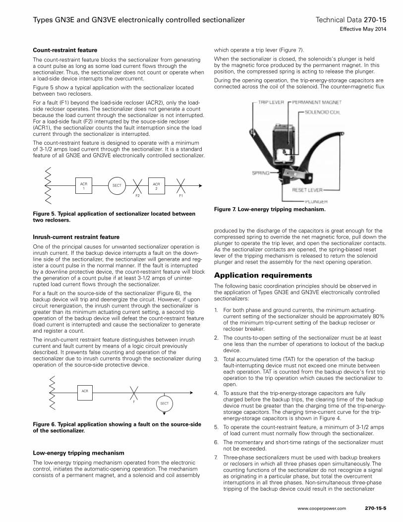
Low-energy tripping mechanism
The low-energy tripping mechanism operated from the electronic control, initiates the automatic-opening operation. The mechanism consists of a permanent magnet, and a solenoid and coil assembly
which operate a trip lever (Figure 7).
When the sectionalizer is closed, the solenoids's plunger is held by the magnetic force produced by the permanent magnet. In this position, the compressed spring is acting to release the plunger.
During the opening operation, the trip-energy-storage capacitors are connected across the coil of the solenoid. The counter-magnetic flux
produced by the discharge of the capacitors is great enough for the compressed spring to override the net magnetic force, pull down the plunger to operate the trip lever, and open the sectionalizer contacts. As the sectionalizer contacts are opened, the spring-biased reset lever of the tripping mechanism is released to return the solenoid plunger and reset the assembly for the next opening operation.
Application requirementsThe following basic coordination principles should be observed in the application of Types GN3E and GN3VE electronically controlled sectionalizers:
1. For both phase and ground currents, the minimum actuating-current setting of the sectionalizer should be approximately 80% of the minimum trip-current setting of the backup recloser or recloser breaker.
2. The counts-to-open setting of the sectionalizer must be at least one less than the number of operations to lockout of the backup device.
3. Total accumulated time (TAT) for the operation of the backup fault-interrupting device must not exceed one minute between each operation. TAT is counted from the backup device's first trip operation to the trip operation which causes the sectionalizer to open.
4. To assure that the trip-energy-storage capacitors are fully charged before the backup trips, the clearing time of the backup device must be greater than the charging time of the trip-energy-storage capacitors. The charging time-current curve for the trip-energy-storage capacitors is shown in Figure 4.
5. To operate the count-restraint feature, a minimum of 3-1/2 amps of load current must normally flow through the sectionalizer.
6. The momentary and short-time ratings of the sectionalizer must not be exceeded.
7. Three-phase sectionalizers must be used with backup breakers or reclosers in which all three phases open simultaneously. The counting functions of the sectionalizer do not recognize a signal as originating in a particular phase, but total the overcurrent interruptions in all three phases. Non-simultaneous three-phase tripping of the backup device could result in the sectionalizer
ACR1
ACR2
SECT
F2 F1
Figure 5. Typical application of sectionalizer located between two reclosers.
ACR
SECTF
Figure 6. Typical application showing a fault on the source-side of the sectionalizer.
Figure 7. Low-energy tripping mechanism.
270-15-5
Technical Data 270-15Effective May 2014
Types GN3E and GN3VE electronically controlled sectionalizer
www.cooperpower.com
interrupting fault current in one or more phases.
8. Application on multi-grounded-wye systems generally required ground-fault sensing and inrush-current restraint. Setting the phase actuating level to the ground setting of the backup device may result in erroneous counts due to inrush currents and incor-rect opening of the sectionalizer for source-side faults.
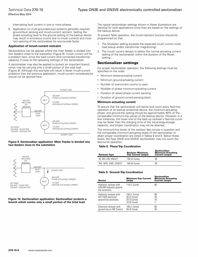
Application of inrush-current restraint
Sectionalizers can be applied where the main feeder is divided into two feeders close to the substation (Figure 8). Inrush current will be a problem here, since the load current (and connected transformer capacity) if close to the operating settings of the sectionalizer.
A sectionalizer may also be applied to protect an important branch which may be carrying only a small portion of the total load (Figure 9). Although this example will result in fewer inrush-current problems than the previous application, inrush-current considerations should not be ignored here.
The typical sectionalizer settings shown in these illustrations are identical for both applications since they are based on the settings of the backup device.
To prevent false operation, the inrush-restraint function should be programmed so that:
1. The Multiplier setting exceeds the expected inrush current (cold-load pickup and/or transformer magnetizing);
2. The inrush current decays to below the normal actuating current setting of the sectionalizer within the duration of the Reset setting.
Sectionalizer settingsFor proper sectionalizer operation, the following settings must be specified on the order: • Minimum phase-actuating current• Minimum ground-actuating current• Number of overcurrent counts to open• Multiple of phase minimum-actuating current• Duration of raised phase current sensing• Duration of ground current-sensing block
Minimum-actuating current
To assure that the sectionalizer will sense and count every fault-trip operation of its backup protective device, the minimum-actuating phase- and ground-trip setting should be approximately 80% of the comparable minimum-trip values of the backup device. However, in a few instances, the lower end of the back-up recloser's fast-trip curve may be faster than the charging time of the trip-energy-storage capacitor, and proper coordination may not be attained.
The minimum-trip levels of the recloser fast curves in question and the comparable minimum-actuating levels of the sectionalizer to attain proper coordination are listed in Tables 8 and 9. Below these levels, the Type GN3E and GN3VE sectionalizer may not count the fast-curve operation.
320-AMPPHASE-ACTUATING-CURRENT
112-AMPGROUND-ACTUATING-CURRENT
SECT
SECT
90-AMP LOAD
110-AMP LOAD
BACKUPRECLOSER
OR BREAKER
200-AMPPEAKLOAD
SETTINGS:400-AMP - PHASE TRIP140-AMP - GROUND TRIP
320-AMPPHASE-ACTUATING-CURRENT
112-AMPGROUND-ACTUATING-CURRENT
Figure 9. Sectionalizer application: Main Feeder is divided into two feeders close to the substation.
320-AMPPHASE-ACTUATING-CURRENT
112-AMPGROUND-ACTUATING-CURRENT
SECT
20-AMP LOAD
BACKUPRECLOSER
OR BREAKER
200-AMPPEAKLOAD
SETTINGS:400-AMP - PHASE TRIP140-AMP - GROUND TRIP
Figure 10. Sectionalizer application: Sectionalizer protects a branch which carries only a small portion of the total load.
Table 8. Phase Trip Coordination
Recloser TypeRecloser Minimum-Trip Current (amps)
Sectionalizer Minimum-Actuating Current (amps)
W, WV, VW, VWV27 100 (A Curve) 80
WE, WVE, VWE, VSVE27 100 (A Curve) 80
Table 9. Ground-Trip Coordination
DeviceMinimum-Trip Current (amps
Sectionalizer Minimum-Actuating Current (amps)
Hydraulic recloser with KA510R hydraulic ground-trip accessory
110 (1 Curve) 80
Hydraulic recloser with KA1144R electronic ground-trip accessory
100 (1 Curve)50 (2 Curve)20 (3 Curve)10 (4 Curve)
8040167
Electronic recloser with ground-trip on ME Control
100 (1 Curve)50 (4 Curve)
8040
270-15-6
Technical Data 270-15Effective May 2014
Types GN3E and GN3VE electronically controlled sectionalizer
www.cooperpower.com
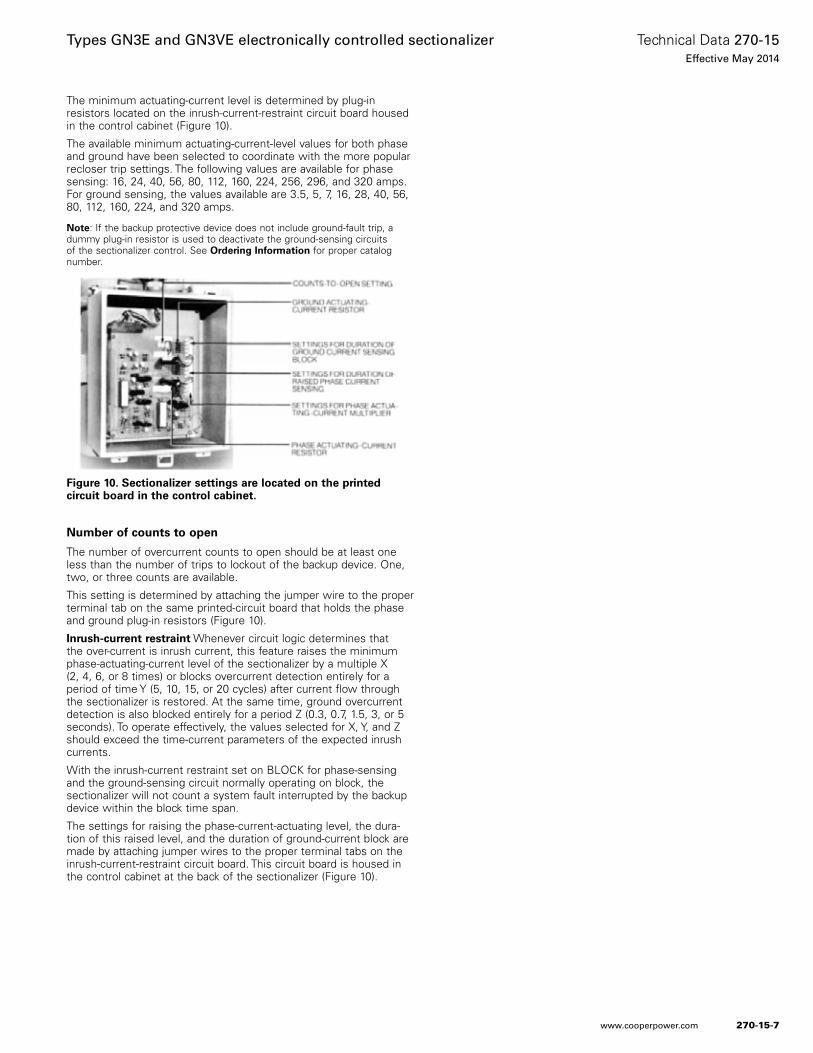
The minimum actuating-current level is determined by plug-in resistors located on the inrush-current-restraint circuit board housed in the control cabinet (Figure 10).
The available minimum actuating-current-level values for both phase and ground have been selected to coordinate with the more popular recloser trip settings. The following values are available for phase sensing: 16, 24, 40, 56, 80, 112, 160, 224, 256, 296, and 320 amps. For ground sensing, the values available are 3.5, 5, 7, 16, 28, 40, 56, 80, 112, 160, 224, and 320 amps.
Note: If the backup protective device does not include ground-fault trip, a dummy plug-in resistor is used to deactivate the ground-sensing circuits of the sectionalizer control. See Ordering Information for proper catalog number.
Number of counts to open
The number of overcurrent counts to open should be at least one less than the number of trips to lockout of the backup device. One, two, or three counts are available.
This setting is determined by attaching the jumper wire to the proper terminal tab on the same printed-circuit board that holds the phase and ground plug-in resistors (Figure 10).
Inrush-current restraint Whenever circuit logic determines that the over-current is inrush current, this feature raises the minimum phase-actuating-current level of the sectionalizer by a multiple X (2, 4, 6, or 8 times) or blocks overcurrent detection entirely for a period of time Y (5, 10, 15, or 20 cycles) after current flow through the sectionalizer is restored. At the same time, ground overcurrent detection is also blocked entirely for a period Z (0.3, 0.7, 1.5, 3, or 5 seconds). To operate effectively, the values selected for X, Y, and Z should exceed the time-current parameters of the expected inrush currents.
With the inrush-current restraint set on BLOCK for phase-sensing and the ground-sensing circuit normally operating on block, the sectionalizer will not count a system fault interrupted by the backup device within the block time span.
The settings for raising the phase-current-actuating level, the dura-tion of this raised level, and the duration of ground-current block are made by attaching jumper wires to the proper terminal tabs on the inrush-current-restraint circuit board. This circuit board is housed in the control cabinet at the back of the sectionalizer (Figure 10).
Figure 10. Sectionalizer settings are located on the printed circuit board in the control cabinet.
270-15-7
Technical Data 270-15Effective May 2014
Types GN3E and GN3VE electronically controlled sectionalizer
www.cooperpower.com
Ratings and specifications
Table 10. Basic Data for Types GN3E and GN3VE Sectionalizers
Description Type GN3E Type GN3VE
Nominal operating voltage (kV rms) 14.4 24.9
Max rated voltage (kV rms) 15.5 27
Impulse withstand (BIL) 1.2 x 50 μsec wave (kV crest) 110 125
60 Hz withstand (KV rms)
dry, 1 min. (kV rms) 50 60
wet, 10 sec. (kV rms) 45 50
Rated continuous current (amps) 200 200
Rated symmetrical load interrupting current (rms amps) 440 440
Rated making current (rms amps; asymmetrical) 9000 9000
Short-time ratings (rms amps) 10 sec, symmetrical 1 sec, symmetrical Momentary, max, asymmetrical
260057009000
260057009000
Table 11. Control Data for Types GN3E and GN3VE Sectionalizers
Minimum Actuating-Current Settings (amps)
Number of Counts to Open Memory Time* (sec) Reset Time** (minutes)Phase-Sensing Ground-Sensing
16, 24, 40, 56, 80, 112, 160, 224, 256, 296, 320
3.5, 7, 16, 28, 40, 56, 80, 112, 160, 224, 320
1, 2, or 3 60 7
* Period of time sectionalizer will retain its count.
** Time required for all count retention to be lost for sectionalizer control operations that do not total the required number of counts to open.
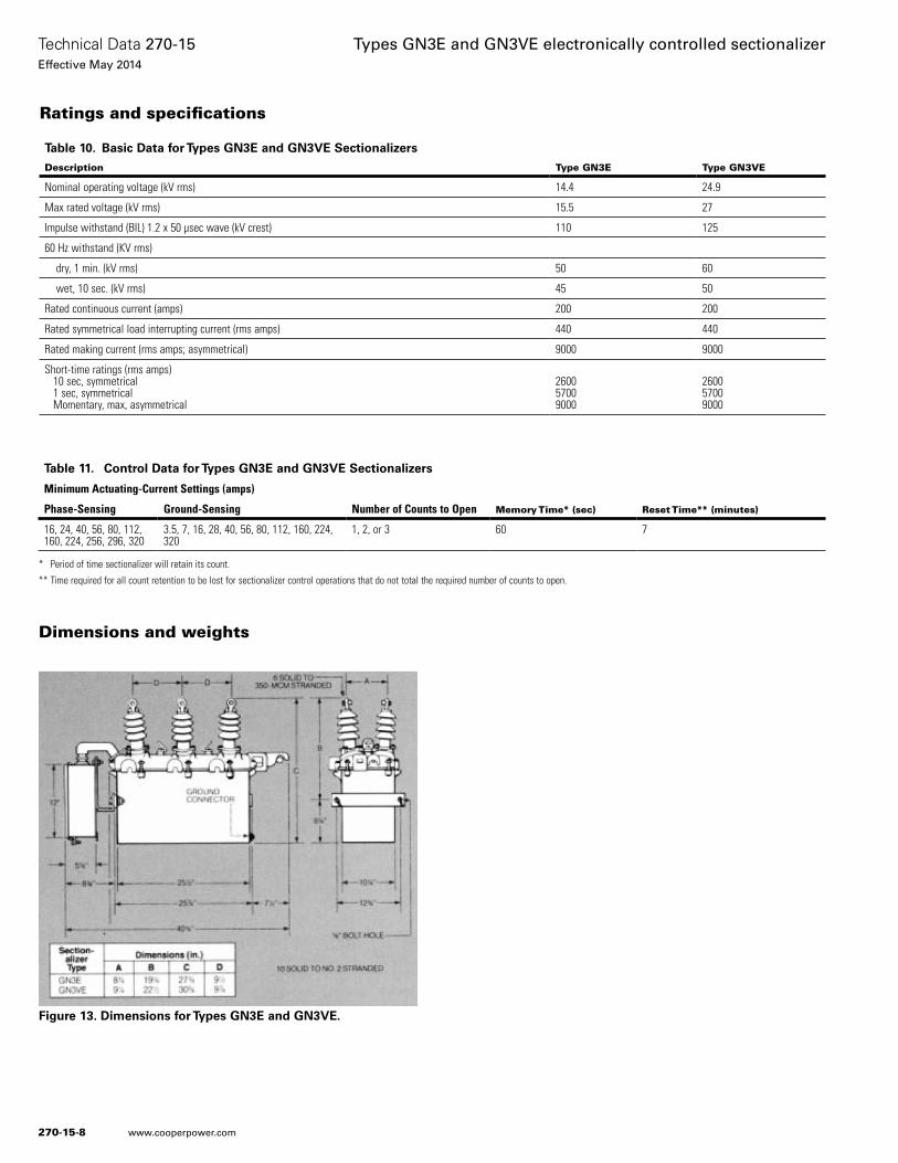
Dimensions and weights
Figure 13. Dimensions for Types GN3E and GN3VE.
270-15-8
Technical Data 270-15Effective May 2014
Types GN3E and GN3VE electronically controlled sectionalizer
www.cooperpower.com
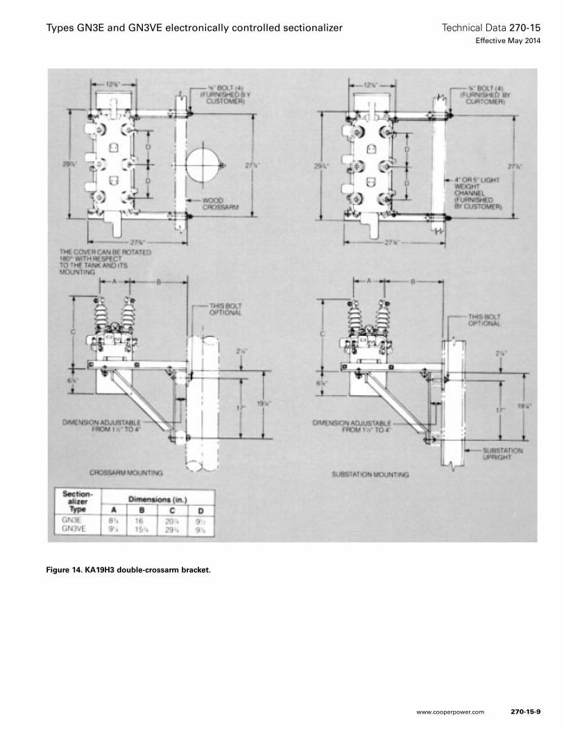
Figure 14. KA19H3 double-crossarm bracket.
270-15-9
Technical Data 270-15Effective May 2014
Types GN3E and GN3VE electronically controlled sectionalizer
www.cooperpower.com
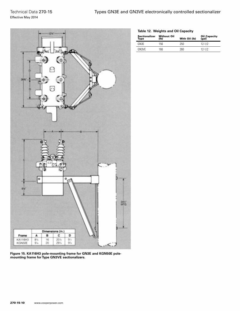
Figure 15. KA116H3 pole-mounting frame for GN3E and KGN50E pole-mounting frame for Type GN3VE sectionalizers.
Table 12. Weights and Oil Capacity
Sectionalizer Type
Without Oil (lb) With Oil (lb)
Oil Capacity (gal)
GN3E 156 250 12-1/2
GN3VE 166 260 12-1/2
270-15-10
Technical Data 270-15Effective May 2014
Types GN3E and GN3VE electronically controlled sectionalizer
www.cooperpower.com
270-15-11
Technical Data 270-15Effective May 2014
Types GN3E and GN3VE electronically controlled sectionalizer
www.cooperpower.com
Eaton and Cooper Power Systems are valuable trademarks of Eaton in the U.S. and other countries. You are not permitted to use the these trademarks without the prior written consent of Eaton.
Types GN3E and GN3VE electronically controlled sectionalizer
Eaton1000 Eaton BoulevardCleveland, OH 44122United StatesEaton.com
Eaton’s Cooper Power Systems Business2300 Badger DriveWaukesha, WI 53188United StatesCooperpower.com
© 2014 EatonAll Rights ReservedPrinted in USAPublication No. 270-15May 2014
Technical Data 270-15Effective May 2014
For Eaton’s Cooper Power Systems Types GN3E and GN3VE sectionalizer product information call 1-877-277-4636 or visit: www.cooperpower.com.
270-15-12
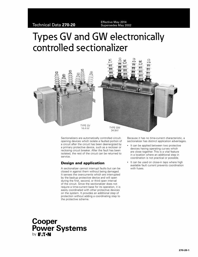
Sectionalizers are automatically controlled circuit-opening devices which isolate a faulted portion of a circuit after the circuit has been deenergized by a primary protective device, such as a recloser or reclosing circuit breaker. After the fault has been isolated, the rest of the circuit can be returned to service.
Design and application A sectionalizer cannot interrupt faults but can be closed in against them without being damaged. It senses the overcurrents which are interrupted by the backup protective device and will open during the first, second, or third open interval of the circuit. Since the sectionalizer does not require a time-current base for its operation, it is easily coordinated with other protective devices on the system. It provides an additional step of protection without adding a coordinating step to the protective scheme.
Because it has no time-current characteristic, a sectionalizer has distinct application advantages. • It can be applied between two protective
devices having operating curves which are close together. This is a vital feature in a location where an additional step in coordination is not practical or possible.
• It can be used on close-in taps where high available fault current prevents coordination with fuses.
Types GV and GW electronically controlled sectionalizer
270-20-1
TYPE GV 14.4 kV TYPE GW
34.5kV
Technical Data 270-20Effective May 2014Supersedes May 2002
Sectionalizers provide several advantages over fuse cutouts. In addition to application flexibility, they offer safety and convenience. After a permanent fault, the fault-closing capability of the sectionalizer greatly simplifies testing the circuit and, if the fault is still present, interruption takes place safely at the backup recloser. Replacement fuse links are not required; thus the line can be tested and service restored with far more speed, convenience, and economy. Also the possibility of error in the selection of the right size and type of replacement fuse link is eliminated.
To improve service continuity and provide more reliable coordination with backup protective devices, the Type GV and GW sectionalizers include the following operating features:
Ground-fault sensing – enables the sectionalizer to coordinate with ground fault tripping reclosers or breakers.
Inrush-current restraint – prevents false counting due to inrush currents that may occur when a circuit is reenergized.
Count-restraint – prevents counting overcurrents interrupted by downline protective devices.
Count reset – provides fast reset of the sectionalizer count memory after successful circuit recloser to better coordinate with backup protective devices.
Ordering information When ordering Type GV or GW sectionalizers, include catalog number and description of basic sectionalizer and the phase and ground minimum-actuating-current plug-in resistors. Also specify the operating settings of the sectionalizer If accessories and/or mounting equipment are required, specify by catalog number and description.
Basic sectionalizer
Specify sectionalizer catalog number:Type GV sectionalizer KGVAType GW sectionalizer KGWA
Minimum-actuating-current
Specify minimum-actuating-current resistors by catalog number:Phase minimum-actuating-current resistor KA176GV___
(Select from 16,24,40,56,80,112,160,224,256,296,320,448,480 or 640 amps)
Ground minimum-actuating-current resistor KA177GV___(Select from 3.5,7,16,20,28,40,56,80,112,160,224,320 amps or BLO [Block])
Operating settings
Specify the following operating settings:
1. Number of counts to open: 1, 2, or 3.
2. Count reset time: 15, 30, 60, 90, 120, or 180 seconds.
Accessories
Sectionalizer accessories are listed in Table 1 by description and catalog number. They are applicable to both Types GV and GW sectionalizers unless otherwise noted.
Mounting equipment
Sectionalizer hangers are listed in Table 2 by description and catalog number.
Summary of ratingsThe Type GV and GW electronically controlled, manually closed, three-phase sectionalizers are rated as follows: • Type GV – 14.4 kV nominal, 400 amps continuous, 110 kV BIL• Type GW – 34.5 kV nominal, 400 amps continuous, 150 kV BIL
The continuous current rating is independent of the minimum actuating current setting of the sectionalizer control.
Also, the operating settings do not affect the capability of the sectionalizers to withstand the full short-circuit rating of 15,000 amps asymmetrical. Both units have a maximum interrupting rating of 880 amps.
Table 1. Sectionalizer Accessories
Description Catalog Number
3-stage auxiliary switch (6 independent contacts)* KA46GV3
17-in creepage distance bushings for Type GV KA170GV1
Low-voltage fuse KA198GV
Slip-on bushing current transformer for Type GW (for field installation only) (three cts per kit)
KA712L2-3
Table 2. Sectionalizer Hangers
Description Catalog Number
For GV Sectionalizer
Double crossarm bracket or substation hanger KA19H3
Pole hanger, broadside mounting KA116H3
Surge arrester mounting bracket for KA116H3 hanger KA126H3
For GW Sectionalizer
Single-pole suspension hanger* KA146W3
Surge arrester mounting bracket for KA146W3 hanger KA126H3
* Supplied with one "a" contact (normally open) and one "b" contact (normally closed) per stage unless specified otherwise.
* Tank lifting windlass for single-pole suspension hanger, KA146W2, cannot be used with Type GW sectionalizer.
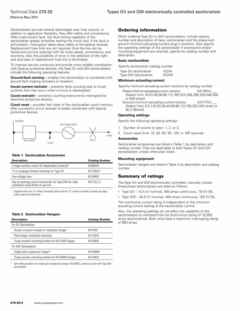
SOURCE
RECLOSER
SECTIONALIZER
LOADFAULT
LOAD
270-20-2
Technical Data 270-20Effective May 2014
Types GV and GW electronically controlled sectionalizer
www.cooperpower.com
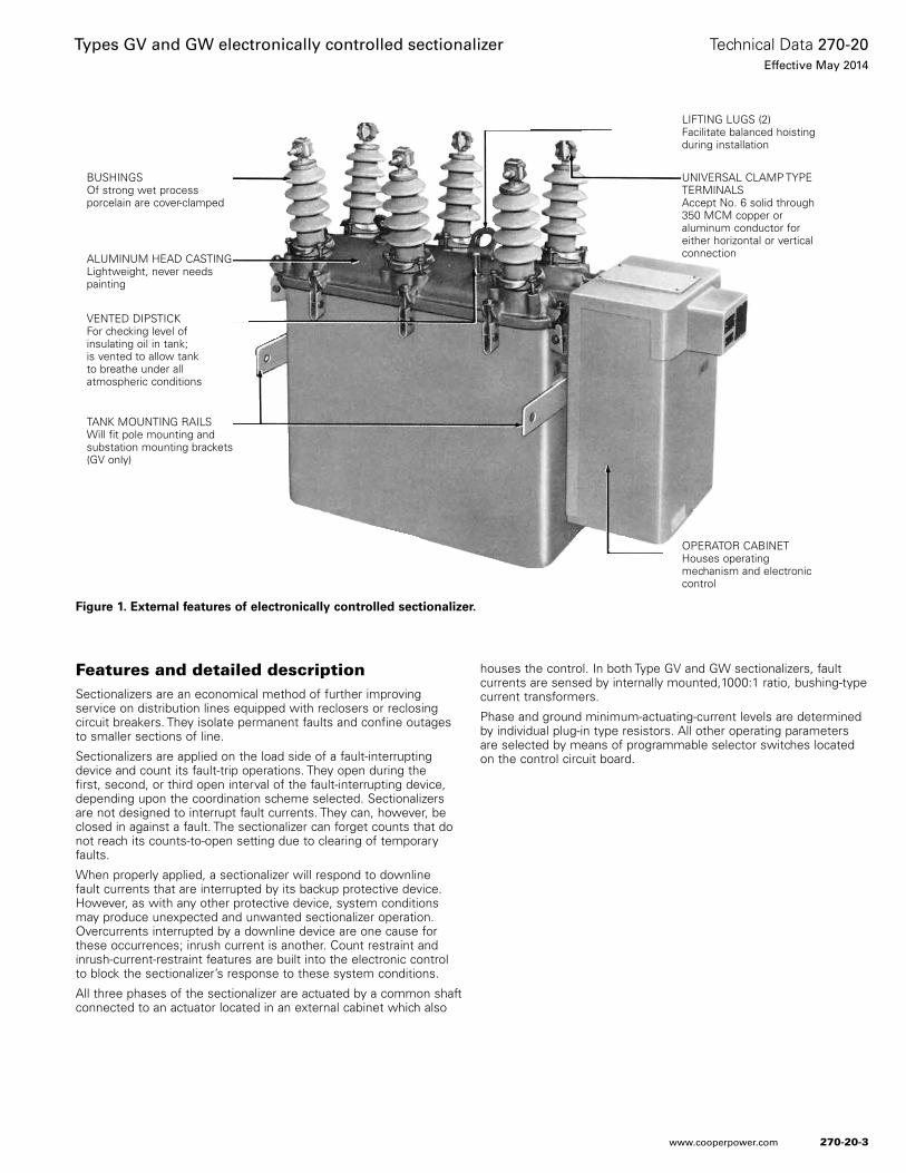
Figure 1. External features of electronically controlled sectionalizer.
Features and detailed descriptionSectionalizers are an economical method of further improving service on distribution lines equipped with reclosers or reclosing circuit breakers. They isolate permanent faults and confine outages to smaller sections of line.
Sectionalizers are applied on the load side of a fault-interrupting device and count its fault-trip operations. They open during the first, second, or third open interval of the fault-interrupting device, depending upon the coordination scheme selected. Sectionalizers are not designed to interrupt fault currents. They can, however, be closed in against a fault. The sectionalizer can forget counts that do not reach its counts-to-open setting due to clearing of temporary faults.
When properly applied, a sectionalizer will respond to downline fault currents that are interrupted by its backup protective device. However, as with any other protective device, system conditions may produce unexpected and unwanted sectionalizer operation. Overcurrents interrupted by a downline device are one cause for these occurrences; inrush current is another. Count restraint and inrush-current-restraint features are built into the electronic control to block the sectionalizer’s response to these system conditions.
All three phases of the sectionalizer are actuated by a common shaft connected to an actuator located in an external cabinet which also
houses the control. In both Type GV and GW sectionalizers, fault currents are sensed by internally mounted,1000:1 ratio, bushing-type current transformers.
Phase and ground minimum-actuating-current levels are determined by individual plug-in type resistors. All other operating parameters are selected by means of programmable selector switches located on the control circuit board.
OPERATOR CABINETHouses operating mechanism and electronic control
LIFTING LUGS (2)Facilitate balanced hoisting during installation
UNIVERSAL CLAMP TYPE TERMINALSAccept No. 6 solid through 350 MCM copper or aluminum conductor for either horizontal or vertical connection
BUSHINGSOf strong wet process porcelain are cover-clamped
ALUMINUM HEAD CASTINGLightweight, never needs painting
VENTED DIPSTICKFor checking level of insulating oil in tank; is vented to allow tank to breathe under all atmospheric conditions
TANK MOUNTING RAILSWill fit pole mounting and substation mounting brackets (GV only)
270-20-3
Technical Data 270-20Effective May 2014
Types GV and GW electronically controlled sectionalizer
www.cooperpower.com
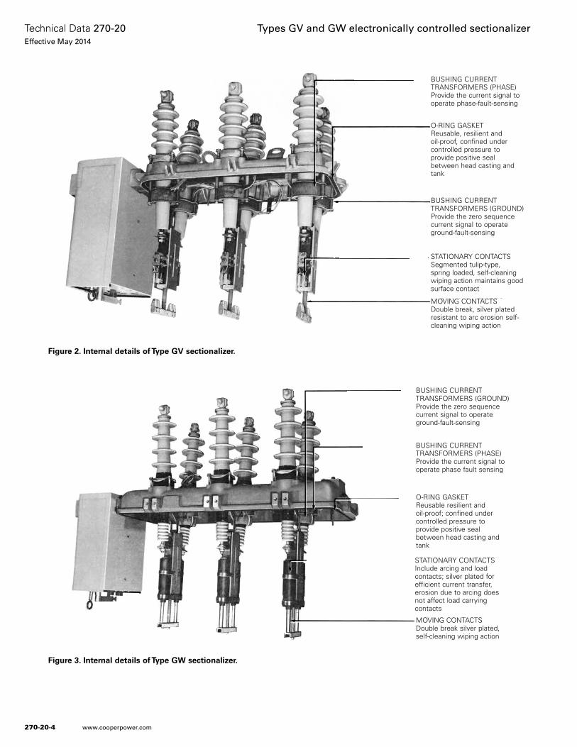
Figure 2. Internal details of Type GV sectionalizer.
Figure 3. Internal details of Type GW sectionalizer.
BUSHING CURRENT TRANSFORMERS (PHASE)Provide the current signal to operate phase-fault-sensing
O-RING GASKETReusable, resilient and oil-proof, confined under controlled pressure to provide positive seal between head casting and tank
BUSHING CURRENT TRANSFORMERS (GROUND)Provide the zero sequence current signal to operate ground-fault-sensing
STATIONARY CONTACTSSegmented tulip-type, spring loaded, self-cleaning wiping action maintains good surface contact
MOVING CONTACTSDouble break, silver plated resistant to arc erosion self-cleaning wiping action
BUSHING CURRENT TRANSFORMERS (GROUND)Provide the zero sequence current signal to operate ground-fault-sensing
BUSHING CURRENT TRANSFORMERS (PHASE)Provide the current signal to operate phase fault sensing
O-RING GASKETReusable resilient and oil-proof; confined under controlled pressure to provide positive seal between head casting and tank
STATIONARY CONTACTSInclude arcing and load contacts; silver plated for efficient current transfer, erosion due to arcing does not affect load carrying contacts
MOVING CONTACTSDouble break silver plated, self-cleaning wiping action
270-20-4
Technical Data 270-20Effective May 2014
Types GV and GW electronically controlled sectionalizer
www.cooperpower.com
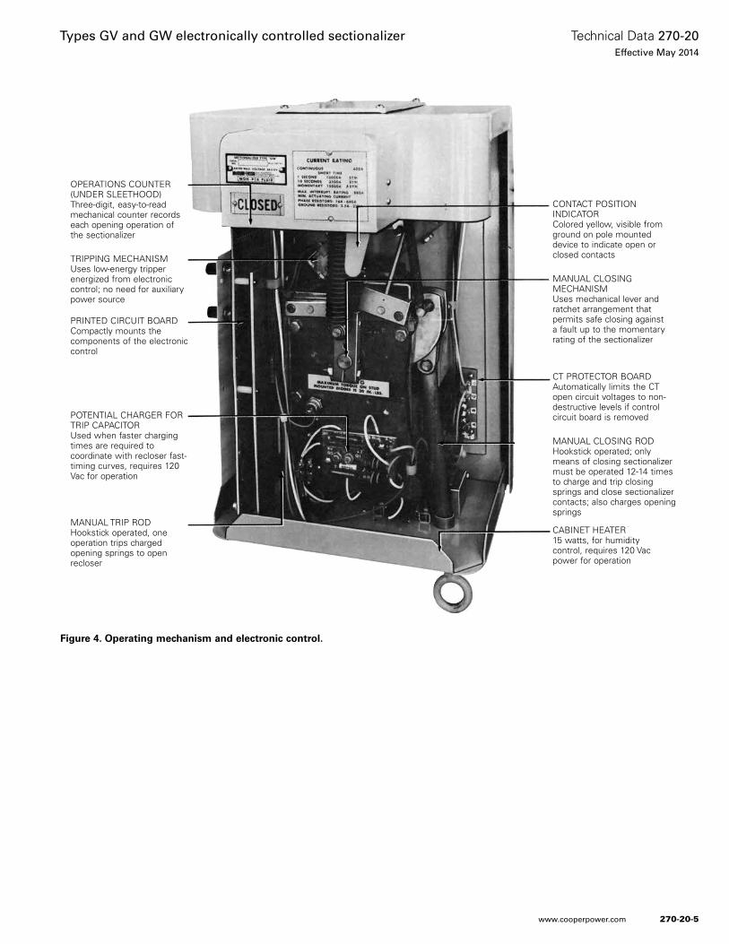
Figure 4. Operating mechanism and electronic control.
CONTACT POSITION INDICATORColored yellow, visible from ground on pole mounted device to indicate open or closed contacts
MANUAL CLOSING MECHANISMUses mechanical lever and ratchet arrangement that permits safe closing against a fault up to the momentary rating of the sectionalizer
CT PROTECTOR BOARDAutomatically limits the CT open circuit voltages to non-destructive levels if control circuit board is removed
MANUAL CLOSING RODHookstick operated; only means of closing sectionalizer must be operated 12-14 times to charge and trip closing springs and close sectionalizer contacts; also charges opening springs
CABINET HEATER15 watts, for humidity control, requires 120 Vac power for operation
OPERATIONS COUNTER (UNDER SLEETHOOD)Three-digit, easy-to-read mechanical counter records each opening operation of the sectionalizer
TRIPPING MECHANISMUses low-energy tripper energized from electronic control; no need for auxiliary power source
PRINTED CIRCUIT BOARDCompactly mounts the components of the electronic control
POTENTIAL CHARGER FOR TRIP CAPACITORUsed when faster charging times are required to coordinate with recloser fast-timing curves, requires 120 Vac for operation
MANUAL TRIP RODHookstick operated, one operation trips charged opening springs to open recloser
270-20-5
Technical Data 270-20Effective May 2014
Types GV and GW electronically controlled sectionalizer
www.cooperpower.com
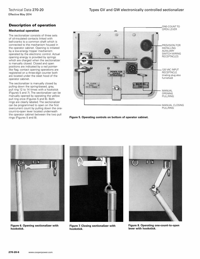
Figure 6. Opening sectionalizer with hookstick.
Figure 7. Closing sectionalizer with hookstick.
Figure 8. Operating one-count-to-open lever with hookstick.
Figure 5. Operating controls on bottom of operator cabinet.
Description of operation Mechanical operation
The sectionalizer consists of three sets of oil-insulated contacts linked with bell-cranks to a common shaft which is connected to the mechanism housed in the operator cabinet. Opening is initiated by a low-energy tripper mechanism operated by the electronic control. Actual opening energy is provided by springs which are charged when the sectionalizer is manually closed. Closed and open positions are indicated by a red pointer-like flag; contact opening operations are registered on a three-digit counter both are located under the sleet hood of the operator cabinet.
The sectionalizer is manually closed by pulling down the spring-biased, gray, pull ring 12 to 14 times with a hookstick (Figures 5 and 7). The sectionalizer can be manually opened by operating the yellow pull ring once (Figures 5 and 6). Both rings are clearly labeled. The sectionalizer can be programmed to open on the first overcurrent count by pulling down the one-count-to-open lever located underneath the operator cabinet between the two pull rings (Figures 5 and 8).
ONE-COUNT TO OPEN LEVER
PROVISION FOR INSTALLING AUXILIARY SWITCH WIRING RECEPTACLES
120 VAC INPUT RECEPTACLE (mating plug also furnished)
MANUAL OPENING PULLRING
MANUAL CLOSING PULLRING
270-20-6
Technical Data 270-20Effective May 2014
Types GV and GW electronically controlled sectionalizer
www.cooperpower.com
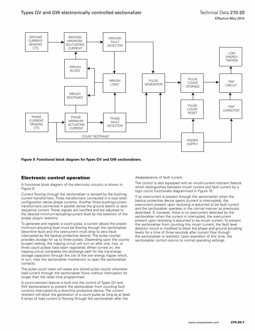
Figure 9. Functional block diagram for Types GV and GW sectionalizers.
GROUNDCURRENT-SENSING
CTS
GROUND-MINIMUM-
ACUTUATINGCURRENT
GROUNDFAULT
DETECTOR
INRUSHBLOCK
INRUSHRESTRAINT
PHASECURRENT-SENSING
CTS
PHASE-MINIMUM-ACTUATINGCURRENT
INRUSHLOGIC
PULSEGENERATOR
PHASEFAULT
DETECTOR
COUNT RESTRAINT
PULSECOUNT
STORAGE
PULSECOUNTRESET
POWERSUPPLY
LOWENERGYTRIPPER
TRIPCIRCUIT
TRIPCAPACITOR
Electronic control operation A functional block diagram of the electronic circuitry is shown in Figure 9.
Current flowing through the sectionalizer is sensed by the bushing-current transformers. Three transformers connected in a wye (star) configuration sense phase currents. Another three bushing-current transformers connected in parallel sense the ground (earth) or zero-sequence current. These signals are rectified and are adjusted to the desired minimum-actuating-current level by the selection of the proper plug-in resistors.
To generate and register a count pulse, a current above the preset-minimum-actuating level must be flowing through the sectionalizer (downline fault) and this overcurrent must drop to zero (fault interrupted by the backup protective device). The pulse counter provides storage for up to three pulses. Depending upon the counts-to-open setting, the tripping circuit will turn on after one, two, or three count pulses have been registered. When turned on, the tripping circuit completes the discharge path for the trip-energy-storage capacitors through the coil of the low energy tripper which, in turn, trips the sectionalizer mechanism to open the sectionalizer contacts.
The pulse count reset will erase any stored pulse counts whenever load current through the sectionalizer flows without interruption for longer than the reset time programmed.
A count-restraint feature is built into the control of Types GV and GW sectionalizers to prevent the sectionalizer from counting fault currents interrupted by a downline protective device. The current restraint will block the generation of a count pulse as long as at least 5 amps of load current is flowing through the sectionalizer after the
disappearance of fault current.
The control is also equipped with an inrush-current restraint feature which distinguishes between inrush current and fault current by a logic circuit functionally diagrammed in Figure 10.
If an overcurrent is present through the sectionalizer when the backup protective device opens (current is interrupted), the overcurrent present upon reclosing is assumed to be fault current and the sectionalizer operates in the normal manner as previously described. If, however, there is no overcurrent detected by the sectionalizer when the current is interrupted, the overcurrent present upon reclosing is assumed to be inrush current. To prevent the sectionalizer from counting this inrush current, the fault level detector circuit is modified to block the phase and ground actuating levels for a time of three seconds after current flow through the sectionalizer is restored. Upon expiration of this time, the sectionalizer control returns to normal operating settings.
270-20-7
Technical Data 270-20Effective May 2014
Types GV and GW electronically controlled sectionalizer
www.cooperpower.com
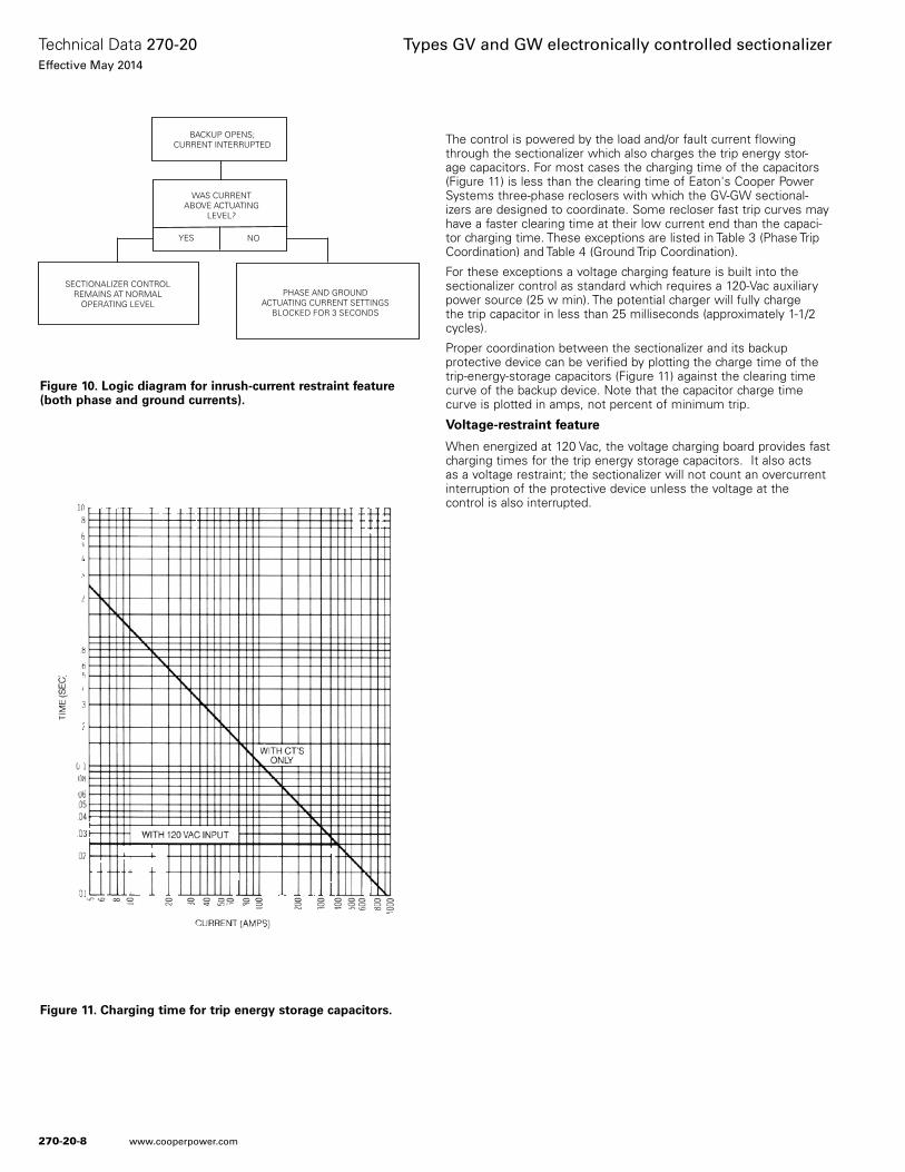
Figure 10. Logic diagram for inrush-current restraint feature (both phase and ground currents).
Figure 11. Charging time for trip energy storage capacitors.
SECTIONALIZER CONTROLREMAINS AT NORMAL
OPERATING LEVEL
WAS CURRENTABOVE ACTUATING
LEVEL?
YES NO
BACKUP OPENS;CURRENT INTERRUPTED
PHASE AND GROUNDACTUATING CURRENT SETTINGS
BLOCKED FOR 3 SECONDS
The control is powered by the load and/or fault current flowing through the sectionalizer which also charges the trip energy stor-age capacitors. For most cases the charging time of the capacitors (Figure 11) is less than the clearing time of Eaton's Cooper Power Systems three-phase reclosers with which the GV-GW sectional-izers are designed to coordinate. Some recloser fast trip curves may have a faster clearing time at their low current end than the capaci-tor charging time. These exceptions are listed in Table 3 (Phase Trip Coordination) and Table 4 (Ground Trip Coordination).
For these exceptions a voltage charging feature is built into the sectionalizer control as standard which requires a 120-Vac auxiliary power source (25 w min). The potential charger will fully charge the trip capacitor in less than 25 milliseconds (approximately 1-1/2 cycles).
Proper coordination between the sectionalizer and its backup protective device can be verified by plotting the charge time of the trip-energy-storage capacitors (Figure 11) against the clearing time curve of the backup device. Note that the capacitor charge time curve is plotted in amps, not percent of minimum trip.
Voltage-restraint feature
When energized at 120 Vac, the voltage charging board provides fast charging times for the trip energy storage capacitors. It also acts as a voltage restraint; the sectionalizer will not count an overcurrent interruption of the protective device unless the voltage at the control is also interrupted.
270-20-8
Technical Data 270-20Effective May 2014
Types GV and GW electronically controlled sectionalizer
www.cooperpower.com
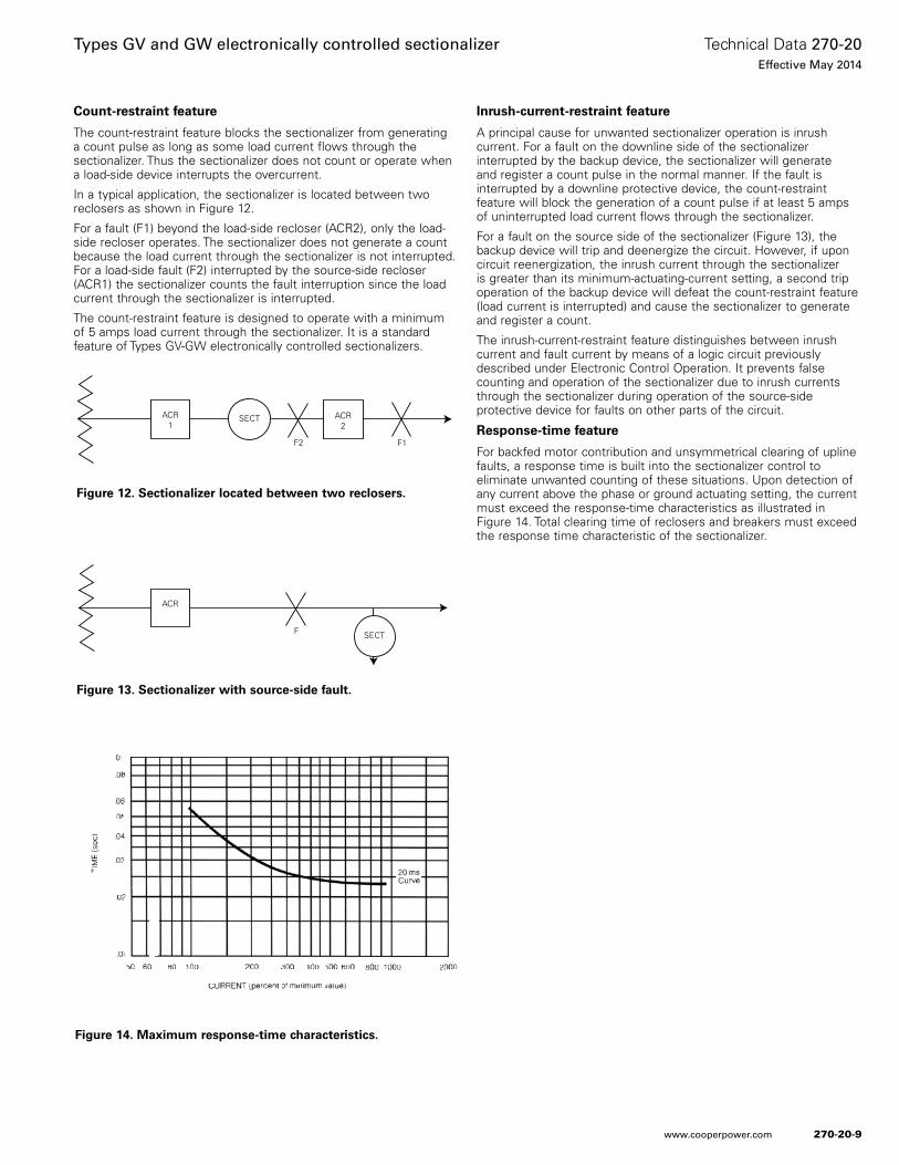
Count-restraint feature
The count-restraint feature blocks the sectionalizer from generating a count pulse as long as some load current flows through the sectionalizer. Thus the sectionalizer does not count or operate when a load-side device interrupts the overcurrent.
In a typical application, the sectionalizer is located between two reclosers as shown in Figure 12.
For a fault (F1) beyond the load-side recloser (ACR2), only the load-side recloser operates. The sectionalizer does not generate a count because the load current through the sectionalizer is not interrupted. For a load-side fault (F2) interrupted by the source-side recloser (ACR1) the sectionalizer counts the fault interruption since the load current through the sectionalizer is interrupted.
The count-restraint feature is designed to operate with a minimum of 5 amps load current through the sectionalizer. It is a standard feature of Types GV-GW electronically controlled sectionalizers.
Inrush-current-restraint feature
A principal cause for unwanted sectionalizer operation is inrush current. For a fault on the downline side of the sectionalizer interrupted by the backup device, the sectionalizer will generate and register a count pulse in the normal manner. If the fault is interrupted by a downline protective device, the count-restraint feature will block the generation of a count pulse if at least 5 amps of uninterrupted load current flows through the sectionalizer.
For a fault on the source side of the sectionalizer (Figure 13), the backup device will trip and deenergize the circuit. However, if upon circuit reenergization, the inrush current through the sectionalizer is greater than its minimum-actuating-current setting, a second trip operation of the backup device will defeat the count-restraint feature (load current is interrupted) and cause the sectionalizer to generate and register a count.
The inrush-current-restraint feature distinguishes between inrush current and fault current by means of a logic circuit previously described under Electronic Control Operation. It prevents false counting and operation of the sectionalizer due to inrush currents through the sectionalizer during operation of the source-side protective device for faults on other parts of the circuit.
Response-time feature
For backfed motor contribution and unsymmetrical clearing of upline faults, a response time is built into the sectionalizer control to eliminate unwanted counting of these situations. Upon detection of any current above the phase or ground actuating setting, the current must exceed the response-time characteristics as illustrated in Figure 14. Total clearing time of reclosers and breakers must exceed the response time characteristic of the sectionalizer.
Figure 12. Sectionalizer located between two reclosers.
Figure 13. Sectionalizer with source-side fault.
Figure 14. Maximum response-time characteristics.
ACR
SECTF
ACR1
ACR2
SECT
F2 F1
270-20-9
Technical Data 270-20Effective May 2014
Types GV and GW electronically controlled sectionalizer
www.cooperpower.com
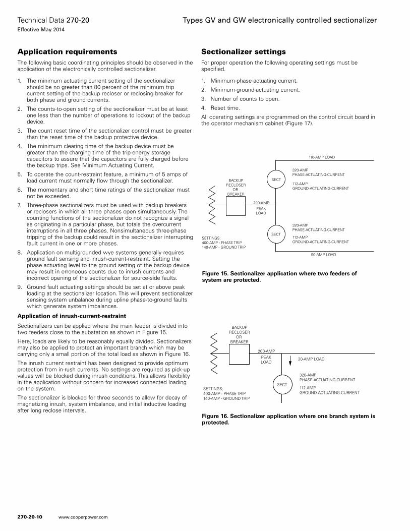
Application requirementsThe following basic coordinating principles should be observed in the application of the electronically controlled sectionalizer.
1. The minimum actuating current setting of the sectionalizer should be no greater than 80 percent of the minimum trip current setting of the backup recloser or reclosing breaker for both phase and ground currents.
2. The counts-to-open setting of the sectionalizer must be at least one less than the number of operations to lockout of the backup device.
3. The count reset time of the sectionalizer control must be greater than the reset time of the backup protective device.
4. The minimum clearing time of the backup device must be greater than the charging time of the trip-energy storage capacitors to assure that the capacitors are fully charged before the backup trips. See Minimum Actuating Current.
5. To operate the count-restraint feature, a minimum of 5 amps of load current must normally flow through the sectionalizer.
6. The momentary and short time ratings of the sectionalizer must not be exceeded.
7. Three-phase sectionalizers must be used with backup breakers or reclosers in which all three phases open simultaneously. The counting functions of the sectionalizer do not recognize a signal as originating in a particular phase, but totals the overcurrent interruptions in all three phases. Nonsimultaneous three-phase tripping of the backup could result in the sectionalizer interrupting fault current in one or more phases.
8. Application on multigrounded wye systems generally requires ground fault sensing and inrush-current-restraint. Setting the phase actuating level to the ground setting of the backup device may result in erroneous counts due to inrush currents and incorrect opening of the sectionalizer for source-side faults.
9. Ground fault actuating settings should be set at or above peak loading at the sectionalizer location. This will prevent sectionalizer sensing system unbalance during upline phase-to-ground faults which generate system imbalances.
Application of inrush-current-restraint
Sectionalizers can be applied where the main feeder is divided into two feeders close to the substation as shown in Figure 15.
Here, loads are likely to be reasonably equally divided. Sectionalizers may also be applied to protect an important branch which may be carrying only a small portion of the total load as shown in Figure 16.
The inrush current restraint has been designed to provide optimum protection from in-rush currents. No settings are required as pick-up values will be blocked during inrush conditions. This allows flexibility in the application without concern for increased connected loading on the system.
The sectionalizer is blocked for three seconds to allow for decay of magnetizing inrush, system imbalance, and initial inductive loading after long reclose intervals.
Sectionalizer settings For proper operation the following operating settings must be specified.
1. Minimum-phase-actuating current.
2. Minimum-ground-actuating current.
3. Number of counts to open.
4. Reset time.
All operating settings are programmed on the control circuit board in the operator mechanism cabinet (Figure 17).
Figure 15. Sectionalizer application where two feeders of system are protected.
320-AMPPHASE-ACTUATING-CURRENT
112-AMPGROUND-ACTUATING-CURRENT
SECT
SECT
90-AMP LOAD
110-AMP LOAD
BACKUPRECLOSER
OR BREAKER
200-AMPPEAKLOAD
SETTINGS:400-AMP - PHASE TRIP140-AMP - GROUND TRIP
320-AMPPHASE-ACTUATING-CURRENT
112-AMPGROUND-ACTUATING-CURRENT
Figure 16. Sectionalizer application where one branch system is protected.
320-AMPPHASE-ACTUATING-CURRENT
112-AMPGROUND-ACTUATING-CURRENT
SECT
20-AMP LOAD
BACKUPRECLOSER
OR BREAKER
200-AMPPEAKLOAD
SETTINGS:400-AMP - PHASE TRIP140-AMP - GROUND TRIP
270-20-10
Technical Data 270-20Effective May 2014
Types GV and GW electronically controlled sectionalizer
www.cooperpower.com
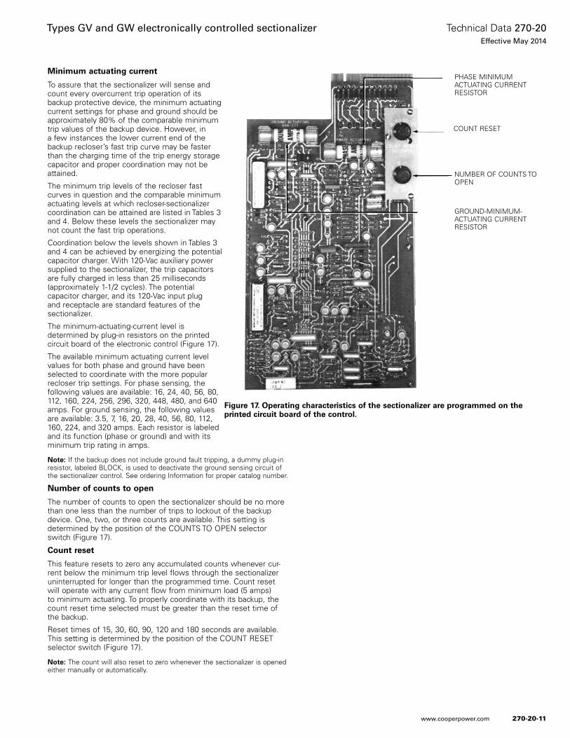
Minimum actuating current
To assure that the sectionalizer will sense and count every overcurrent trip operation of its backup protective device, the minimum actuating current settings for phase and ground should be approximately 80% of the comparable minimum trip values of the backup device. However, in a few instances the lower current end of the backup recloser’s fast trip curve may be faster than the charging time of the trip energy storage capacitor and proper coordination may not be attained.
The minimum trip levels of the recloser fast curves in question and the comparable minimum actuating levels at which recloser-sectionalizer coordination can be attained are listed in Tables 3 and 4. Below these levels the sectionalizer may not count the fast trip operations.
Coordination below the levels shown in Tables 3 and 4 can be achieved by energizing the potential capacitor charger. With 120-Vac auxiliary power supplied to the sectionalizer, the trip capacitors are fully charged in less than 25 milliseconds (approximately 1-1/2 cycles). The potential capacitor charger, and its 120-Vac input plug and receptacle are standard features of the sectionalizer.
The minimum-actuating-current level is determined by plug-in resistors on the printed circuit board of the electronic control (Figure 17).
The available minimum actuating current level values for both phase and ground have been selected to coordinate with the more popular recloser trip settings. For phase sensing, the following values are available: 16, 24, 40, 56, 80, 112, 160, 224, 256, 296, 320, 448, 480, and 640 amps. For ground sensing, the following values are available: 3.5, 7, 16, 20, 28, 40, 56, 80, 112, 160, 224, and 320 amps. Each resistor is labeled and its function (phase or ground) and with its minimum trip rating in amps.
otee:N If the backup does not include ground fault tripping, a dummy plug-in resistor, labeled BLOCK, is used to deactivate the ground sensing circuit of the sectionalizer control. See ordering Information for proper catalog number.
Number of counts to open
The number of counts to open the sectionalizer should be no more than one less than the number of trips to lockout of the backup device. One, two, or three counts are available. This setting is determined by the position of the COUNTS TO OPEN selector switch (Figure 17).
Count reset
This feature resets to zero any accumulated counts whenever cur-rent below the minimum trip level flows through the sectionalizer uninterrupted for longer than the programmed time. Count reset will operate with any current flow from minimum load (5 amps) to minimum actuating. To properly coordinate with its backup, the count reset time selected must be greater than the reset time of the backup.
Reset times of 15, 30, 60, 90, 120 and 180 seconds are available. This setting is determined by the position of the COUNT RESET selector switch (Figure 17).
otee:N The count will also reset to zero whenever the sectionalizer is opened either manually or automatically.
Figure 17. Operating characteristics of the sectionalizer are programmed on the printed circuit board of the control.
PHASE MINIMUM ACTUATING CURRENT RESISTOR
COUNT RESET
NUMBER OF COUNTS TO OPEN
GROUND-MINIMUM-ACTUATING CURRENT RESISTOR
270-20-11
Technical Data 270-20Effective May 2014
Types GV and GW electronically controlled sectionalizer
www.cooperpower.com
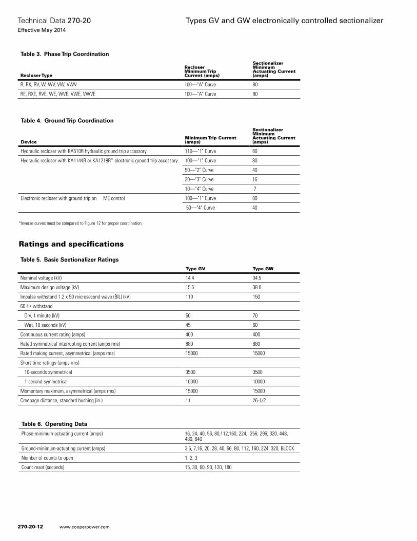
Ratings and specifications
Table 3. Phase Trip Coordination
Recloser Type
RecloserMinimum TripCurrent (amps)
Sectionalizer MinimumActuating Current(amps)
R, RX, RV, W, WV, VW, VWV 100—"A" Curve 80
RE, RXE, RVE, WE, WVE, VWE, VWVE 100—"A" Curve 80
Table 4. Ground Trip Coordination
DeviceMinimum Trip Current(amps)
Sectionalizer Minimum Actuating Current(amps)
Hydraulic recloser with KA510R hydraulic ground trip accessory 110—"1" Curve 80
Hydraulic recloser with KA1144R or KA1219R* electronic ground trip accessory 100—"1" Curve 80
50—"2" Curve 40
20—"3" Curve 16
10—"4" Curve 7
Electronic recloser with ground trip on ME control 100—"1" Curve 80
50—"4" Curve 40
Table 5. Basic Sectionalizer Ratings
Type GV Type GW
Nominal voltage (kV) 14.4 34.5
Maximum design voltage (kV) 15.5 38.0
Impulse withstand 1.2 x 50 microsecond wave (BIL) (kV) 110 150
60 Hz withstand
Dry, 1 minute (kV) 50 70
Wet, 10 seconds (kV) 45 60
Continuous current rating (amps) 400 400
Rated symmetrical interrupting current (amps rms) 880 880
Rated making current, asymmetrical (amps rms) 15000 15000
Short-time ratings (amps rms)
10-seconds symmetrical 3500 3500
1-second symmetrical 10000 10000
Momentary maximum, asymmetrical (amps rms) 15000 15000
Creepage distance, standard bushing (in ) 11 26-1/2
*Inverse curves must be compared to Figure 12 for proper coordination.
Table 6. Operating Data
Phase-minimum-actuating current (amps) 16, 24, 40, 56, 80,112,160, 224, 256, 296, 320, 448, 480, 640
Ground-minimum-actuating current (amps) 3.5, 7,16, 20, 28, 40, 56, 80, 112, 160, 224, 320, BLOCK
Number of counts to open 1, 2, 3
Count reset (seconds) 15, 30, 60, 90, 120, 180
270-20-12
Technical Data 270-20Effective May 2014
Types GV and GW electronically controlled sectionalizer
www.cooperpower.com

Figure 19. Type GW sectionalizer.
Figure 18. Type GV sectionalizer.
Dimensional information
270-20-13
Technical Data 270-20Effective May 2014
Types GV and GW electronically controlled sectionalizer
www.cooperpower.com
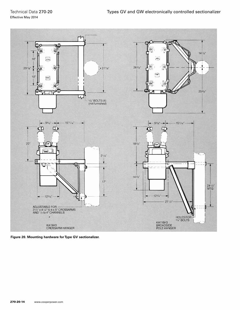
Figure 20. Mounting hardware for Type GV sectionalizer.
270-20-14
Technical Data 270-20Effective May 2014
Types GV and GW electronically controlled sectionalizer
www.cooperpower.com
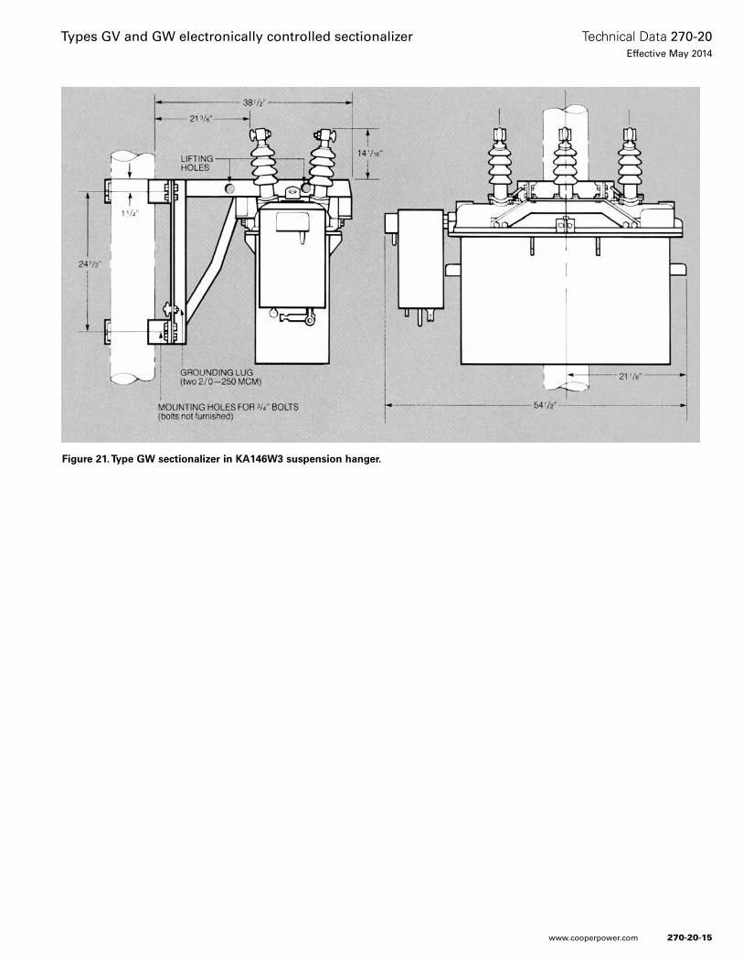
Figure 21. Type GW sectionalizer in KA146W3 suspension hanger.
270-20-15
Technical Data 270-20Effective May 2014
Types GV and GW electronically controlled sectionalizer
www.cooperpower.com

Eaton and Cooper Power Systems are valuable trademarks of Eaton in the U.S. and other countries. You are not permitted to use the these trademarks without the prior written consent of Eaton.
Types GV and GW electronically controlled sectionalizer
Eaton1000 Eaton BoulevardCleveland, OH 44122United StatesEaton.com
Eaton’s Cooper Power Systems Business2300 Badger DriveWaukesha, WI 53188United StatesCooperpower.com
© 2014 EatonAll Rights ReservedPrinted in USAPublication No. 270-20May 2014
Technical Data 270-20Effective May 2014
For Eaton’s Cooper Power Systems GV and GW sectionalizer product information call 1-877-277-4636 or visit: www.cooperpower.com.
270-20-16
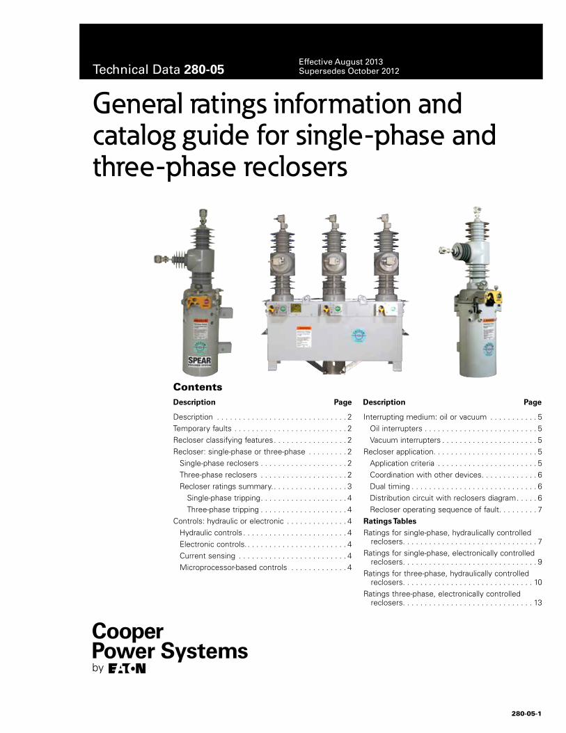
280-05-1
Description . . . . . . . . . . . . . . . . . . . . . . . . . . . . . . 2Temporary faults . . . . . . . . . . . . . . . . . . . . . . . . . . 2Recloser classifying features . . . . . . . . . . . . . . . . . 2Recloser: single-phase or three-phase . . . . . . . . . 2 Single-phase reclosers . . . . . . . . . . . . . . . . . . . . 2 Three-phase reclosers . . . . . . . . . . . . . . . . . . . . 2 Recloser ratings summary . . . . . . . . . . . . . . . . . . 3 Single-phase tripping . . . . . . . . . . . . . . . . . . . . 4
Three-phase tripping . . . . . . . . . . . . . . . . . . . . 4Controls: hydraulic or electronic . . . . . . . . . . . . . . 4 Hydraulic controls . . . . . . . . . . . . . . . . . . . . . . . . 4 Electronic controls . . . . . . . . . . . . . . . . . . . . . . . . 4 Current sensing . . . . . . . . . . . . . . . . . . . . . . . . . 4 Microprocessor-based controls . . . . . . . . . . . . . 4
Interrupting medium: oil or vacuum . . . . . . . . . . . 5 Oil interrupters . . . . . . . . . . . . . . . . . . . . . . . . . . 5 Vacuum interrupters . . . . . . . . . . . . . . . . . . . . . . 5Recloser application . . . . . . . . . . . . . . . . . . . . . . . . 5 Application criteria . . . . . . . . . . . . . . . . . . . . . . . 5 Coordination with other devices . . . . . . . . . . . . . 6 Dual timing . . . . . . . . . . . . . . . . . . . . . . . . . . . . . 6 Distribution circuit with reclosers diagram . . . . . 6 Recloser operating sequence of fault . . . . . . . . . 7Ratings TablesRatings for single-phase, hydraulically controlled
reclosers . . . . . . . . . . . . . . . . . . . . . . . . . . . . . . . 7Ratings for single-phase, electronically controlled
reclosers . . . . . . . . . . . . . . . . . . . . . . . . . . . . . . . 9Ratings for three-phase, hydraulically controlled
reclosers . . . . . . . . . . . . . . . . . . . . . . . . . . . . . . 10Ratings three-phase, electronically controlled
reclosers . . . . . . . . . . . . . . . . . . . . . . . . . . . . . . 13
General ratings information and catalog guide for single-phase and three-phase reclosers
ContentsDescription Page Description Page
Technical Data 280-05Effective August 2013 Supersedes October 2012
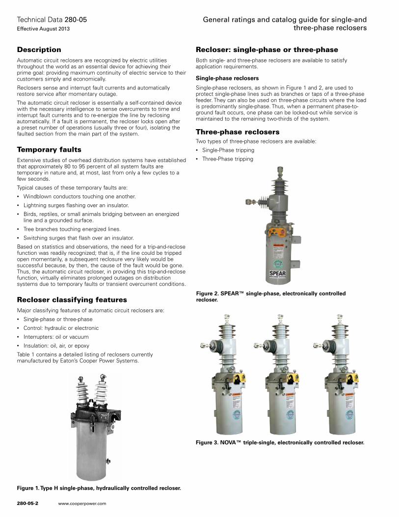
280-05-2
Technical Data 280-05Effective August 2013
General ratings and catalog guide for single-and three-phase reclosers
www.cooperpower.com
DescriptionAutomatic circuit reclosers are recognized by electric utilities throughout the world as an essential device for achieving their prime goal: providing maximum continuity of electric service to their customers simply and economically .
Reclosers sense and interrupt fault currents and automatically restore service after momentary outage .
The automatic circuit recloser is essentially a self-contained device with the necessary intelligence to sense overcurrents to time and interrupt fault currents and to re-energize the line by reclosing automatically . If a fault is permanent, the recloser locks open after a preset number of operations (usually three or four), isolating the faulted section from the main part of the system .
Temporary faultsExtensive studies of overhead distribution systems have established that approximately 80 to 95 percent of all system faults are temporary in nature and, at most, last from only a few cycles to a few seconds .
Typical causes of these temporary faults are:• Windblown conductors touching one another .• Lightning surges flashing over an insulator .• Birds, reptiles, or small animals bridging between an energized
line and a grounded surface .• Tree branches touching energized lines .• Switching surges that flash over an insulator .
Based on statistics and observations, the need for a trip-and-reclose function was readily recognized; that is, if the line could be tripped open momentarily, a subsequent reclosure very likely would be successful because, by then, the cause of the fault would be gone . Thus, the automatic circuit recloser, in providing this trip-and-reclose function, virtually eliminates prolonged outages on distribution systems due to temporary faults or transient overcurrent conditions .
Recloser classifying featuresMajor classifying features of automatic circuit reclosers are: • Single-phase or three-phase• Control: hydraulic or electronic• Interrupters: oil or vacuum• Insulation: oil, air, or epoxy
Table 1 contains a detailed listing of reclosers currently manufactured by Eaton’s Cooper Power Systems .
Recloser: single-phase or three-phaseBoth single- and three-phase reclosers are available to satisfy application requirements .
Single-phase reclosers
Single-phase reclosers, as shown in Figure 1 and 2, are used to protect single-phase lines such as branches or taps of a three-phase feeder . They can also be used on three-phase circuits where the load is predominantly single-phase . Thus, when a permanent phase-to-ground fault occurs, one phase can be locked-out while service is maintained to the remaining two-thirds of the system .
Three-phase reclosersTwo types of three-phase reclosers are available:• Single-Phase tripping• Three-Phase tripping
Figure 3. NOVA™ triple-single, electronically controlled recloser.
Figure 1. Type H single-phase, hydraulically controlled recloser.
Figure 2. SPEAR™ single-phase, electronically controlled recloser.

280-05-3
Technical Data 280-05Effective August 2013
General ratings information and catalog guide for single-and three-phase reclosers
www.cooperpower.com
* Interrupting rating will be higher at lower voltage as shown in expanded tables.
** Continuous current rating can be extended to 800 A with an accessory.
*** For pad-mounted installation.
† 16.0 kA option is also available.
Table 1. Recloser Ratings Summary (See Tables 2–5 for more detailed ratings data)
VoltageRating(kV)
Max. Cont.CurrentRating(A)
InterruptingRating(sym A atmax. voltage)
InterruptingMedium Control
RecloserType
Single-Phase
2.4 - 14.4
50 1250 Oil Hydraulic H100 2000* Oil Hydraulic 4H200 2000* Vacuum Hydraulic V4H280 4000* Oil Hydraulic L280 6000 Vacuum Hydraulic V4L560 10000* Oil Hydraulic D400 8000 Vacuum Electronic SPEAR15-8630 12500 Vacuum Electronic SPEAR15-12800 12500 Vacuum Electronic SPEAR15-12
24.9
100 2500 Oil Hydraulic E280 4000 Oil Hydraulic 4E280 6000 Vacuum Hydraulic V4E400 8000 Vacuum Electronic SPEAR27-8630 12500 Vacuum Electronic SPEAR27-12800 12500 Vacuum Electronic SPEAR27-12
24.9 - 34.5
560 8000 Oil Hydraulic DV400 8000 Vacuum Electronic SPEAR38-8630 12500 Vacuum Electronic SPEAR38-12800 12500 Vacuum Electronic SPEAR38-12
Three-Phase
2.4 - 14.4
100 2000* Oil Hydraulic 6H200 2000* Oil Hydraulic V6H400 8000 Vacuum Electronic NOVA-TS-15-8560 10000* Oil Hydraulic W560** 10000* Oil Electronic WE560 12000 Vacuum Hydraulic VW560 12000 Vacuum Electronic PWE***560** 12000 Vacuum Electronic VWE600 12000 Vacuum Electronic VSA12B630** 12500† Vacuum Electronic NOVA™ 15800 12000 Vacuum Electronic VSA12800 16000 Vacuum Electronic VSA16800 20000 Vacuum Electronic VSA20630** 12500† Vacuum Electronic NOVA-TS-15-12630** 12500† Vacuum Electronic NOVA STS-151200 20000 Vacuum Electronic VSA20A
24.9
400 8000 Vacuum Electronic NOVA-TS-27-8560 8000 Oil Hydraulic WV27560** 8000 Oil Electronic WVE27560 12000 Vacuum Hydraulic VWV27560** 12000 Vacuum Electronic VWVE27560 12000 Vacuum Electronic PWVE***630** 12500† Vacuum Electronic NOVA 27630** 12500† Vacuum Electronic NOVA-TS-27-12630** 12500† Vacuum Electronic NOVA STS-27
34.5
400 8000 Vacuum Electronic NOVA-TS-38-8560 8000 Oil Hydraulic WV38X560** 8000 Oil Electronic WVE38X560 12000 Vacuum Hydraulic VWV38X560** 12000 Vacuum Electronic VWVE38X560** 12000 Vacuum Electronic VSO12560** 16000 Vacuum Electronic VSO16630** 12500 Vacuum Electronic NOVA 38630** 12500 Vacuum Electronic NOVA-TS-38-12630** 12500 Vacuum Electronic NOVA STS-38
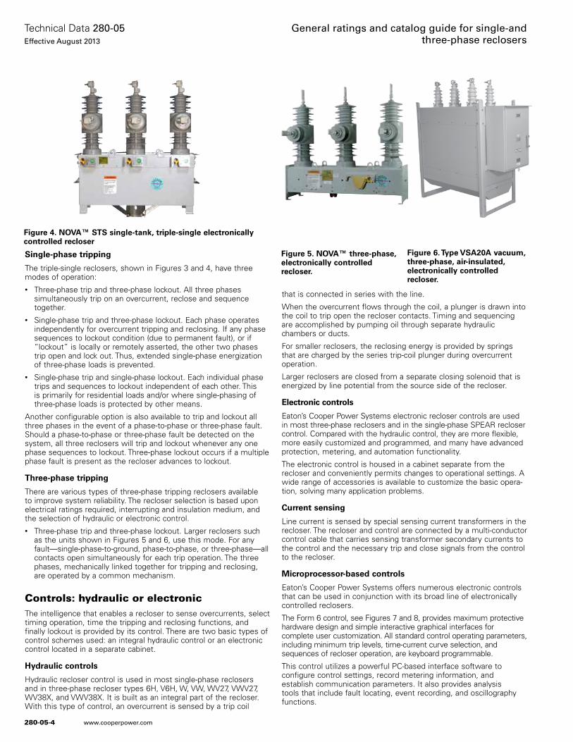
280-05-4
Technical Data 280-05Effective August 2013
General ratings and catalog guide for single-and three-phase reclosers
www.cooperpower.com
Single-phase tripping
The triple-single reclosers, shown in Figures 3 and 4, have three modes of operation:• Three-phase trip and three-phase lockout . All three phases
simultaneously trip on an overcurrent, reclose and sequence together .
• Single-phase trip and three-phase lockout . Each phase operates independently for overcurrent tripping and reclosing . If any phase sequences to lockout condition (due to permanent fault), or if “lockout” is locally or remotely asserted, the other two phases trip open and lock out . Thus, extended single-phase energization of three-phase loads is prevented .
• Single-phase trip and single-phase lockout . Each individual phase trips and sequences to lockout independent of each other . This is primarily for residential loads and/or where single-phasing of three-phase loads is protected by other means .
Another configurable option is also available to trip and lockout all three phases in the event of a phase-to-phase or three-phase fault . Should a phase-to-phase or three-phase fault be detected on the system, all three reclosers will trip and lockout whenever any one phase sequences to lockout . Three-phase lockout occurs if a multiple phase fault is present as the recloser advances to lockout .
Three-phase tripping
There are various types of three-phase tripping reclosers available to improve system reliability . The recloser selection is based upon electrical ratings required, interrupting and insulation medium, and the selection of hydraulic or electronic control .• Three-phase trip and three-phase lockout . Larger reclosers such
as the units shown in Figures 5 and 6, use this mode . For any fault—single-phase-to-ground, phase-to-phase, or three-phase—all contacts open simultaneously for each trip operation . The three phases, mechanically linked together for tripping and reclosing, are operated by a common mechanism .
Controls: hydraulic or electronicThe intelligence that enables a recloser to sense overcurrents, select timing operation, time the tripping and reclosing functions, and finally lockout is provided by its control . There are two basic types of control schemes used: an integral hydraulic control or an electronic control located in a separate cabinet .
Hydraulic controls
Hydraulic recloser control is used in most single-phase reclosers and in three-phase recloser types 6H, V6H, W, VW, WV27, VWV27, WV38X, and VWV38X . It is built as an integral part of the recloser . With this type of control, an overcurrent is sensed by a trip coil
that is connected in series with the line .
When the overcurrent flows through the coil, a plunger is drawn into the coil to trip open the recloser contacts . Timing and sequencing are accomplished by pumping oil through separate hydraulic chambers or ducts .
For smaller reclosers, the reclosing energy is provided by springs that are charged by the series trip-coil plunger during overcurrent operation .
Larger reclosers are closed from a separate closing solenoid that is energized by line potential from the source side of the recloser .
Electronic controls
Eaton’s Cooper Power Systems electronic recloser controls are used in most three-phase reclosers and in the single-phase SPEAR recloser control . Compared with the hydraulic control, they are more flexible, more easily customized and programmed, and many have advanced protection, metering, and automation functionality .
The electronic control is housed in a cabinet separate from the recloser and conveniently permits changes to operational settings . A wide range of accessories is available to customize the basic opera-tion, solving many application problems .
Current sensing
Line current is sensed by special sensing current transformers in the recloser . The recloser and control are connected by a multi-conductor control cable that carries sensing transformer secondary currents to the control and the necessary trip and close signals from the control to the recloser .
Microprocessor-based controls
Eaton’s Cooper Power Systems offers numerous electronic controls that can be used in conjunction with its broad line of electronically controlled reclosers .
The Form 6 control, see Figures 7 and 8, provides maximum protective hardware design and simple interactive graphical interfaces for complete user customization . All standard control operating parameters, including minimum trip levels, time-current curve selection, and sequences of recloser operation, are keyboard programmable .
This control utilizes a powerful PC-based interface software to configure control settings, record metering information, and establish communication parameters . It also provides analysis tools that include fault locating, event recording, and oscillography functions .
Figure 5. NOVA™ three-phase, electronically controlled recloser.
Figure 6. Type VSA20A vacuum, three-phase, air-insulated, electronically controlled recloser.
Figure 4. NOVA™ STS single-tank, triple-single electronically controlled recloser
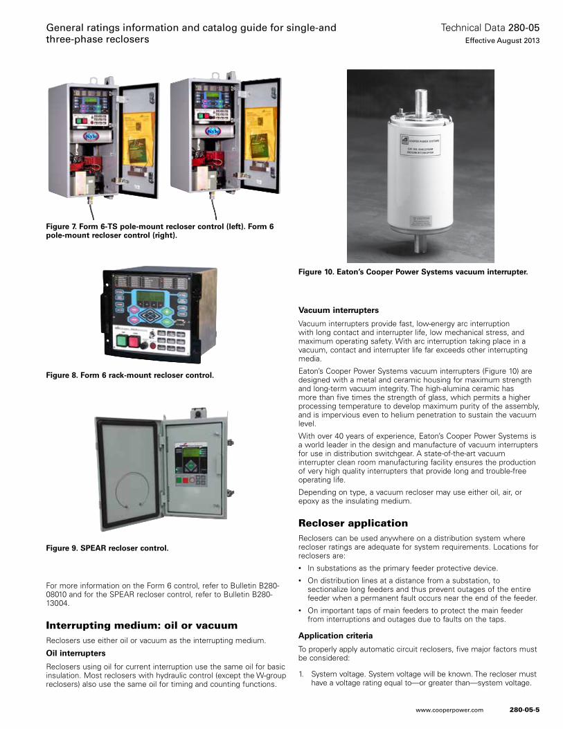
280-05-5
Technical Data 280-05Effective August 2013
General ratings information and catalog guide for single-and three-phase reclosers
www.cooperpower.com
For more information on the Form 6 control, refer to Bulletin B280-08010 and for the SPEAR recloser control, refer to Bulletin B280-13004 .
Interrupting medium: oil or vacuumReclosers use either oil or vacuum as the interrupting medium .
Oil interrupters
Reclosers using oil for current interruption use the same oil for basic insulation . Most reclosers with hydraulic control (except the W-group reclosers) also use the same oil for timing and counting functions .
Vacuum interrupters
Vacuum interrupters provide fast, low-energy arc interruption with long contact and interrupter life, low mechanical stress, and maximum operating safety . With arc interruption taking place in a vacuum, contact and interrupter life far exceeds other interrupting media .
Eaton’s Cooper Power Systems vacuum interrupters (Figure 10) are designed with a metal and ceramic housing for maximum strength and long-term vacuum integrity . The high-alumina ceramic has more than five times the strength of glass, which permits a higher processing temperature to develop maximum purity of the assembly, and is impervious even to helium penetration to sustain the vacuum level .
With over 40 years of experience, Eaton’s Cooper Power Systems is a world leader in the design and manufacture of vacuum interrupters for use in distribution switchgear . A state-of-the-art vacuum interrupter clean room manufacturing facility ensures the production of very high quality interrupters that provide long and trouble-free operating life .
Depending on type, a vacuum recloser may use either oil, air, or epoxy as the insulating medium .
Recloser applicationReclosers can be used anywhere on a distribution system where recloser ratings are adequate for system requirements . Locations for reclosers are:• In substations as the primary feeder protective device .• On distribution lines at a distance from a substation, to
sectionalize long feeders and thus prevent outages of the entire feeder when a permanent fault occurs near the end of the feeder .
• On important taps of main feeders to protect the main feeder from interruptions and outages due to faults on the taps .
Application criteria
To properly apply automatic circuit reclosers, five major factors must be considered:
1 . System voltage . System voltage will be known . The recloser must have a voltage rating equal to—or greater than—system voltage .
Figure 7. Form 6-TS pole-mount recloser control (left). Form 6 pole-mount recloser control (right).
Figure 8. Form 6 rack-mount recloser control.
Figure 10. Eaton’s Cooper Power Systems vacuum interrupter.
Figure 9. SPEAR recloser control.
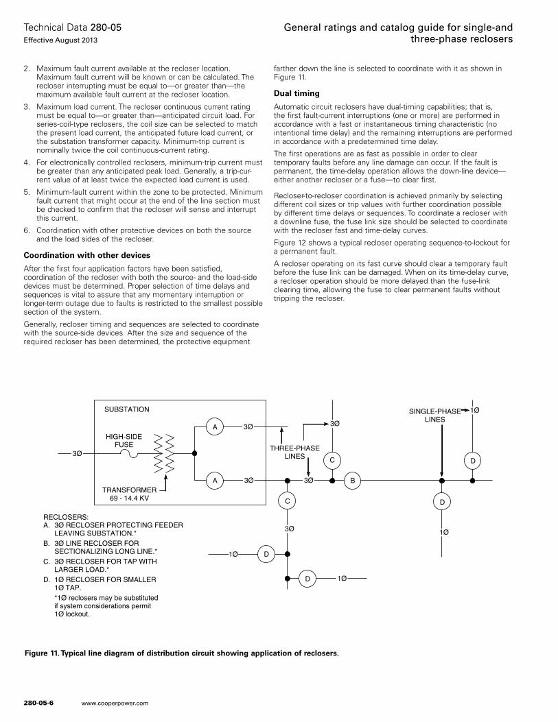
280-05-6
Technical Data 280-05Effective August 2013
General ratings and catalog guide for single-and three-phase reclosers
www.cooperpower.com
2 . Maximum fault current available at the recloser location . Maximum fault current will be known or can be calculated . The recloser interrupting must be equal to—or greater than—the maximum available fault current at the recloser location .
3 . Maximum load current . The recloser continuous current rating must be equal to—or greater than—anticipated circuit load . For series-coil-type reclosers, the coil size can be selected to match the present load current, the anticipated future load current, or the substation transformer capacity . Minimum-trip current is nominally twice the coil continuous-current rating .
4 . For electronically controlled reclosers, minimum-trip current must be greater than any anticipated peak load . Generally, a trip-cur-rent value of at least twice the expected load current is used .
5 . Minimum-fault current within the zone to be protected . Minimum fault current that might occur at the end of the line section must be checked to confirm that the recloser will sense and interrupt this current .
6 . Coordination with other protective devices on both the source and the load sides of the recloser .
Coordination with other devices
After the first four application factors have been satisfied, coordination of the recloser with both the source- and the load-side devices must be determined . Proper selection of time delays and sequences is vital to assure that any momentary interruption or longer-term outage due to faults is restricted to the smallest possible section of the system .
Generally, recloser timing and sequences are selected to coordinate with the source-side devices . After the size and sequence of the required recloser has been determined, the protective equipment
farther down the line is selected to coordinate with it as shown in Figure 11 .
Dual timing
Automatic circuit reclosers have dual-timing capabilities; that is, the first fault-current interruptions (one or more) are performed in accordance with a fast or instantaneous timing characteristic (no intentional time delay) and the remaining interruptions are performed in accordance with a predetermined time delay .
The first operations are as fast as possible in order to clear temporary faults before any line damage can occur . If the fault is permanent, the time-delay operation allows the down-line device—either another recloser or a fuse—to clear first .
Recloser-to-recloser coordination is achieved primarily by selecting different coil sizes or trip values with further coordination possible by different time delays or sequences . To coordinate a recloser with a downline fuse, the fuse link size should be selected to coordinate with the recloser fast and time-delay curves .
Figure 12 shows a typical recloser operating sequence-to-lockout for a permanent fault .
A recloser operating on its fast curve should clear a temporary fault before the fuse link can be damaged . When on its time-delay curve, a recloser operation should be more delayed than the fuse-link clearing time, allowing the fuse to clear permanent faults without tripping the recloser .
SUBSTATION
HIGH-SIDEFUSE
TRANSFORMER69 - 14.4 KV
THREE-PHASELINES
SINGLE-PHASELINES
A
C
A
D
D
B
C D
D
3Ø RECLOSER PROTECTING FEEDERLEAVING SUBSTATION.*3Ø LINE RECLOSER FORSECTIONALIZING LONG LINE.*3Ø RECLOSER FOR TAP WITHLARGER LOAD.*1Ø RECLOSER FOR SMALLER1Ø TAP.*1Ø reclosers may be substitutedif system considerations permit1Ø lockout.
RECLOSERS:A.
B.
C.
D.
3Ø
1Ø
1Ø
1Ø
3Ø
3Ø 3Ø
3Ø
1Ø
3Ø
Figure 11. Typical line diagram of distribution circuit showing application of reclosers.
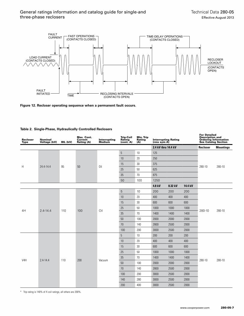
280-05-7
Technical Data 280-05Effective August 2013
General ratings information and catalog guide for single-and three-phase reclosers
www.cooperpower.com
* Trip rating is 140% of X coil ratings, all others are 200%.
Table 2. Single-Phase, Hydraulically Controlled Reclosers
FAULTCURRENT
FAULTINITIATED
LOAD CURRENT(CONTACTS CLOSED)
FAST OPERATIONS(CONTACTS CLOSED)
TIME-DELAY OPERATIONS(CONTACTS CLOSED)
RECLOSING INTERVALS(CONTACTS OPEN)TIME
RECLOSERLOCKOUT
(CONTACTSOPEN)
Figure 12. Recloser operating sequence when a permanent fault occurs.
Recloser Type
Nominal Voltage (kV) BIL (kV)
Max. Cont. Current Rating (A)
Interrupting Medium
Trip-Coil Rating (cont. A)
Min. Trip Rating (A)
Interrupting Rating (rms sym A)
For Detailed Description and Ordering Information See Catalog Section
2.4 kV thru 14.4 kV Recloser Mountings
H 24.4-14.4 95 50 Oil
5 10 125
280-10 280-10
10 20 250
15 30 375
25 50 625
35 70 875
50 100 1250
4.8 kV 8.32 kV 14.4 kV
4H 2 .4-14 .4 110 100 Oil
5 10 200 200 200
280-10 280-10
10 20 400 400 400
15 30 600 600 600
25 50 1000 1000 1000
35 70 1400 1400 1400
50 100 2000 2000 2000
70 140 2800 2500 2000
100 200 3000 2500 2000
V4H 2.4-14.4 110 200 Vacuum
5 10 200 200 200
280-10 280-10
10 20 400 400 400
15 30 600 600 600
25 50 1000 1000 1000
35 70 1400 1400 1400
50 100 2000 2000 2000
70 140 2800 2500 2000
100 200 3000 2500 2000
140 280 3000 2500 2000
200 400 3000 2500 2000
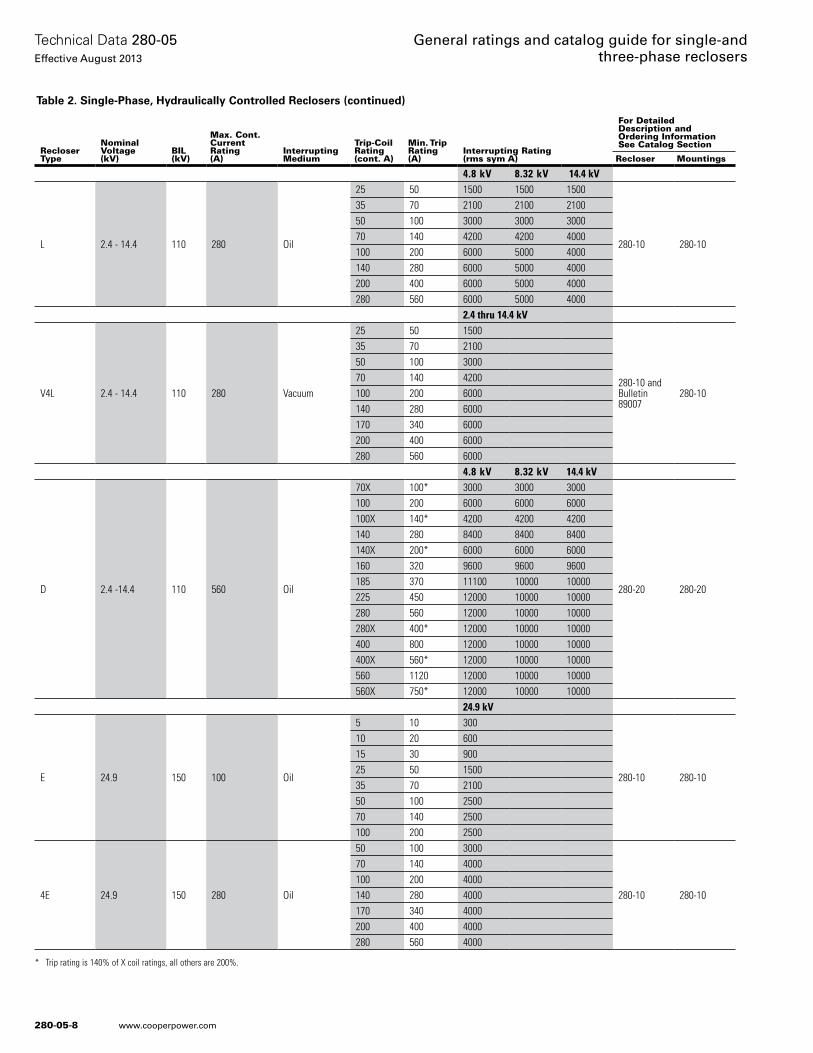
280-05-8
Technical Data 280-05Effective August 2013
General ratings and catalog guide for single-and three-phase reclosers
www.cooperpower.com
Table 2. Single-Phase, Hydraulically Controlled Reclosers (continued)
* Trip rating is 140% of X coil ratings, all others are 200%.
RecloserType
NominalVoltage(kV)
BIL(kV)
Max. Cont. CurrentRating(A)
InterruptingMedium
Trip-Coil Rating(cont. A)
Min. TripRating(A)
Interrupting Rating(rms sym A)
For Detailed Description and Ordering InformationSee Catalog Section
Recloser Mountings
4.8 kV 8.32 kV 14.4 kV
L 2.4 - 14.4 110 280 Oil
25 50 1500 1500 1500
280-10 280-10
35 70 2100 2100 210050 100 3000 3000 300070 140 4200 4200 4000100 200 6000 5000 4000140 280 6000 5000 4000200 400 6000 5000 4000280 560 6000 5000 4000
2.4 thru 14.4 kV
V4L 2.4 - 14.4 110 280 Vacuum
25 50 1500
280-10 andBulletin 89007
280-10
35 70 210050 100 300070 140 4200100 200 6000140 280 6000170 340 6000200 400 6000280 560 6000
4.8 kV 8.32 kV 14.4 kV
D 2.4 -14.4 110 560 Oil
70X 100* 3000 3000 3000
280-20 280-20
100 200 6000 6000 6000100X 140* 4200 4200 4200140 280 8400 8400 8400140X 200* 6000 6000 6000160 320 9600 9600 9600185 370 11100 10000 10000225 450 12000 10000 10000280 560 12000 10000 10000280X 400* 12000 10000 10000400 800 12000 10000 10000400X 560* 12000 10000 10000560 1120 12000 10000 10000560X 750* 12000 10000 10000
24.9 kV
E 24.9 150 100 Oil
5 10 300
280-10 280-10
10 20 60015 30 90025 50 150035 70 210050 100 250070 140 2500100 200 2500
4E 24.9 150 280 Oil
50 100 3000
280-10 280-10
70 140 4000100 200 4000140 280 4000170 340 4000200 400 4000280 560 4000
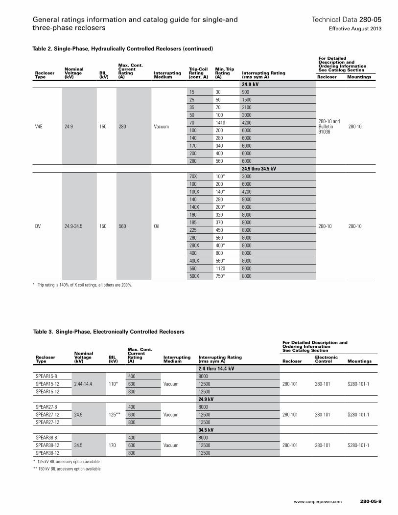
280-05-9
Technical Data 280-05Effective August 2013
General ratings information and catalog guide for single-and three-phase reclosers
www.cooperpower.com
Table 2. Single-Phase, Hydraulically Controlled Reclosers (continued)
* Trip rating is 140% of X coil ratings, all others are 200%.
* 125 kV BIL accessory option available
** 150 kV BIL accessory option available
Table 3. Single-Phase, Electronically Controlled Reclosers
RecloserType
NominalVoltage(kV)
BIL(kV)
Max. Cont. CurrentRating(A)
InterruptingMedium
Trip-Coil Rating(cont. A)
Min. TripRating(A)
Interrupting Rating(rms sym A)
For Detailed Description and Ordering InformationSee Catalog Section
Recloser Mountings
24.9 kV
V4E 24.9 150 280 Vacuum
15 30 900
280-10 and Bulletin 91036
280-10
25 50 150035 70 210050 100 300070 1410 4200100 200 6000140 280 6000170 340 6000200 400 6000280 560 6000
24.9 thru 34.5 kV
DV 24.9-34.5 150 560 Oil
70X 100* 3000
280-10 280-10
100 200 6000100X 140* 4200140 280 8000140X 200* 6000160 320 8000185 370 8000225 450 8000280 560 8000280X 400* 8000400 800 8000400X 560* 8000560 1120 8000560X 750* 8000
RecloserType
NominalVoltage(kV)
BIL(kV)
Max. Cont. CurrentRating(A)
InterruptingMedium
Interrupting Rating(rms sym A)
For Detailed Description and Ordering InformationSee Catalog Section
RecloserElectronic Control Mountings
2.4 thru 14.4 kVSPEAR15-8
2.44-14.4 110*400
Vacuum8000
280-101 280-101 S280-101-1SPEAR15-12 630 12500SPEAR15-12 800 12500
24.9 kVSPEAR27-8
24.9 125**400
Vacuum8000
280-101 280-101 S280-101-1SPEAR27-12 630 12500SPEAR27-12 800 12500
34.5 kVSPEAR38-8
34.5 170400
Vacuum8000
280-101 280-101 S280-101-1SPEAR38-12 630 12500SPEAR38-12 800 12500
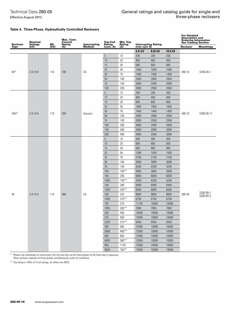
280-05-10
Technical Data 280-05Effective August 2013
General ratings and catalog guide for single-and three-phase reclosers
www.cooperpower.com
Table 4. Three-Phase, Hydraulically Controlled Reclosers
* Phases trip individually on overcurrent, but trip and lock out all three phases at the final step in sequence. Other reclosers operate all three phases simultaneously under all conditions.
** Trip rating is 140% of X coil ratings, all others are 200%.
RecloserType
NominalVoltage(kV)
BIL(kV)
Max. Cont. CurrentRating(A)
InterruptingMedium
Trip-Coil Rating(cont. A)
Min. TripRating(A)
Interrupting Rating(rms sym A)
For Detailed Description and Ordering InformationSee Catalog Section
Recloser Mountings
4.8 kV 8.32 kV 14.4 kV
6H* 2.4-14.4 110 100 Oil
5 10 200 200 200
280-10 S280-85-1
10 20 400 400 40015 30 600 600 60025 50 1000 1000 100035 70 1400 1400 140050 100 2000 2000 200070 140 2800 2500 2000100 200 3000 2500 2000
V6H* 2.4-14.4 110 200 Vacuum
5 10 200 200 200
280-10 S280-85-11
10 20 400 400 40015 30 600 600 60025 50 1000 1000 100035 70 1400 1400 140050 100 2000 2000 200070 140 2800 2500 2000100 200 3000 2500 2000140 280 3000 2500 2000200 400 3000 2500 2000
W 2.4-14.4 110 560 Oil
5 10 300 300 300
280-30 S280-85-1S280-85-2
10 20 600 600 60015 30 900 900 90025 50 1500 1500 150035 70 2100 2100 210050 100 3000 3000 300070 140 4200 4200 420070X 100** 3000 3000 3000100 200 6000 6000 6000100X 140** 4200 4200 4200140 280 8400 8400 8400140X 200** 6000 6000 6000160 320 9600 9600 9600160X 225** 6750 6750 6750185 370 11100 10000 10000185X 260** 7800 7800 7800200 400 12000 10000 10000225 450 12000 10000 10000225X 315** 9450 9450 9450280 560 12000 10000 10000280X 400** 12000 10000 10000400 800 12000 10000 10000400X 560** 12000 10000 10000560 1120 12000 10000 10000560X 750** 12000 10000 10000
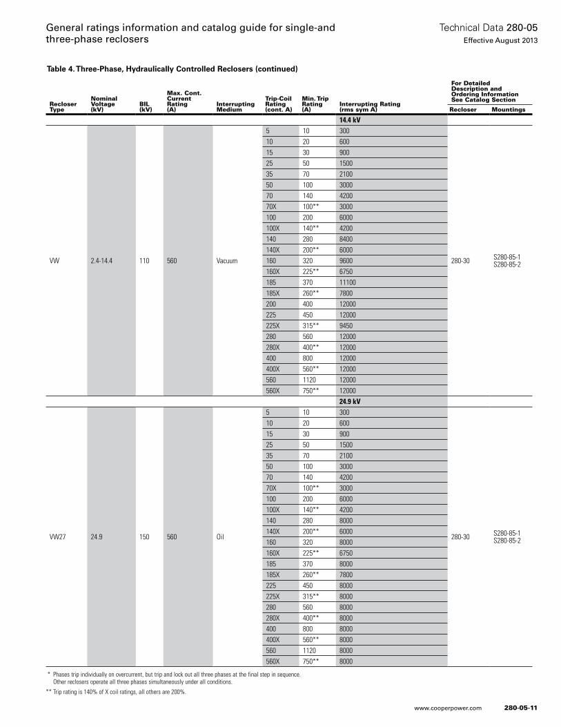
280-05-11
Technical Data 280-05Effective August 2013
General ratings information and catalog guide for single-and three-phase reclosers
www.cooperpower.com
Table 4. Three-Phase, Hydraulically Controlled Reclosers (continued)
* Phases trip individually on overcurrent, but trip and lock out all three phases at the final step in sequence. Other reclosers operate all three phases simultaneously under all conditions.
** Trip rating is 140% of X coil ratings, all others are 200%.
RecloserType
NominalVoltage(kV)
BIL(kV)
Max. Cont.CurrentRating(A)
InterruptingMedium
Trip-CoilRating(cont. A)
Min. TripRating(A)
Interrupting Rating(rms sym A)
For Detailed Description and Ordering InformationSee Catalog Section
Recloser Mountings
14.4 kV
VW 2.4-14.4 110 560 Vacuum
5 10 300
280-30 S280-85-1S280-85-2
10 20 60015 30 90025 50 150035 70 210050 100 300070 140 420070X 100** 3000100 200 6000100X 140** 4200140 280 8400140X 200** 6000160 320 9600160X 225** 6750185 370 11100185X 260** 7800200 400 12000225 450 12000225X 315** 9450280 560 12000280X 400** 12000400 800 12000400X 560** 12000560 1120 12000560X 750** 12000
24.9 kV
VW27 24.9 150 560 Oil
5 10 300
280-30 S280-85-1S280-85-2
10 20 60015 30 90025 50 150035 70 210050 100 300070 140 420070X 100** 3000100 200 6000100X 140** 4200140 280 8000140X 200** 6000160 320 8000160X 225** 6750185 370 8000185X 260** 7800225 450 8000225X 315** 8000280 560 8000280X 400** 8000400 800 8000400X 560** 8000560 1120 8000560X 750** 8000
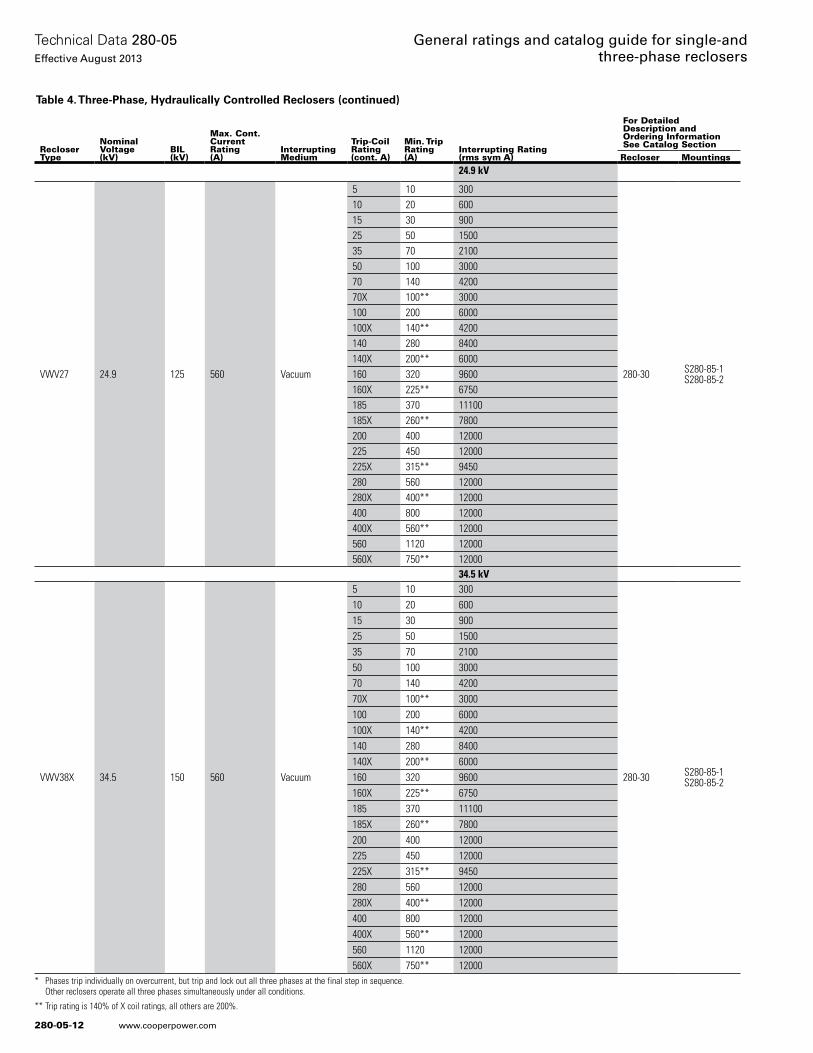
280-05-12
Technical Data 280-05Effective August 2013
General ratings and catalog guide for single-and three-phase reclosers
www.cooperpower.com
Table 4. Three-Phase, Hydraulically Controlled Reclosers (continued)
* Phases trip individually on overcurrent, but trip and lock out all three phases at the final step in sequence. Other reclosers operate all three phases simultaneously under all conditions.
** Trip rating is 140% of X coil ratings, all others are 200%.
RecloserType
NominalVoltage(kV)
BIL(kV)
Max. Cont.CurrentRating(A)
InterruptingMedium
Trip-CoilRating(cont. A)
Min. TripRating(A)
Interrupting Rating(rms sym A)
For Detailed Description and Ordering InformationSee Catalog SectionRecloser Mountings
24.9 kV
VWV27 24.9 125 560 Vacuum
5 10 300
280-30 S280-85-1S280-85-2
10 20 60015 30 90025 50 150035 70 210050 100 300070 140 420070X 100** 3000100 200 6000100X 140** 4200140 280 8400140X 200** 6000160 320 9600160X 225** 6750185 370 11100185X 260** 7800200 400 12000225 450 12000225X 315** 9450280 560 12000280X 400** 12000400 800 12000400X 560** 12000560 1120 12000560X 750** 12000
34.5 kV
VWV38X 34.5 150 560 Vacuum
5 10 300
280-30 S280-85-1S280-85-2
10 20 60015 30 90025 50 150035 70 210050 100 300070 140 420070X 100** 3000100 200 6000100X 140** 4200140 280 8400140X 200** 6000160 320 9600160X 225** 6750185 370 11100185X 260** 7800200 400 12000225 450 12000225X 315** 9450280 560 12000280X 400** 12000400 800 12000400X 560** 12000560 1120 12000560X 750** 12000
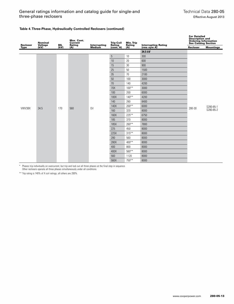
280-05-13
Technical Data 280-05Effective August 2013
General ratings information and catalog guide for single-and three-phase reclosers
www.cooperpower.com
Table 4. Three-Phase, Hydraulically Controlled Reclosers (continued)
* Phases trip individually on overcurrent, but trip and lock out all three phases at the final step in sequence. Other reclosers operate all three phases simultaneously under all conditions.
** Trip rating is 140% of X coil ratings, all others are 200%.
RecloserType
NominalVoltage(kV)
BIL(kV)
Max. Cont.CurrentRating(A)
InterruptingMedium
Trip-CoilRating(cont. A)
Min. TripRating(A)
Interrupting Rating(rms sym A)
For Detailed Description and Ordering InformationSee Catalog Section
Recloser Mountings
34.5 kV
VWV38X 34.5 170 560 Oil
5 10 300
280-30 S280-85-1S280-85-2
10 20 60015 30 90025 50 150035 70 210050 100 300070 140 420070X 100** 3000100 200 6000100X 140** 4200140 280 8400140X 200** 6000160 320 8000160X 225** 6750185 370 8000185X 260** 7800225 450 8000225X 315** 8000280 560 8000280X 400** 8000400 800 8000400X 560** 8000560 1120 8000560X 750** 8000
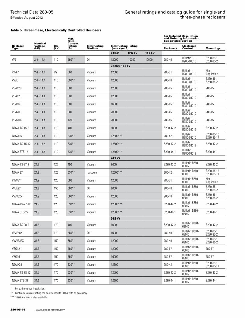
280-05-14
Technical Data 280-05Effective August 2013
General ratings and catalog guide for single-and three-phase reclosers
www.cooperpower.com
Table 5. Three-Phase, Electronically Controlled Reclosers
* For pad-mounted installation.
** Continuous current rating can be extended to 800 A with an accessory.
*** 16.0 kA option is also available.
RecloserType
NominalVoltage(kV)
BIL(kV)
Max.Cont.CurrentRating(A)
InterruptingMedium
Interrupting Rating (rms sym A)
For Detailed Descriptionand Ordering InformationSee Catalog Section
ReclosersElectronicControl Mountings
4.8 kV 8.32 kV 14.4 kV
WE 2.4 - 14.4 110 560** Oil 12000 10000 10000 280-40 Bulletin B280-08010
S280-85-1S280-85-2
2.4 thru 14.4 kV
PWE* 2.4 - 14.4 95 560 Vacuum 12000 285-71 Bulletin B280-08010
NotApplicable
VWE 2.4 - 14.4 110 560** Vacuum 12000 280-40 Bulletin B280-08010
S280-85-1S280-85-2
VSA12B 2.4 - 14.4 110 600 Vacuum 12000 280-45 Bulletin B280-08010 280-45
VSA12 2.4 - 14.4 110 800 Vacuum 12000 280-45 Bulletin B280-08010 280-45
VSA16 2.4 - 14.4 110 800 Vacuum 16000 280-45 Bulletin B280-08010 280-45
VSA20 2.4 - 14.4 110 800 Vacuum 20000 280-45 Bulletin B280-08010 280-45
VSA20A 2.4 - 14.4 110 1200 Vacuum 20000 280-45 Bulletin B280-08010 280-45
NOVA-TS-15-8 2.4 - 14.4 110 400 Vacuum 8000 S280-42-2 Bulletin B280-08012 S280-42-2
NOVA15 2.4 - 14.4 110 630** Vacuum 12500*** 280-42 Bulletin B280-08010
S280-85-16S280-85-17
NOVA-TS-15-12 2.4 - 14.4 110 630** Vacuum 12500*** S280-42-2 Bulletin B280-08012 S280-42-2
NOVA STS-15 2.4 - 14.4 110 630** Vacuum 12500*** S280-44-1 Bulletin B280-08012 S280-44-1
24.9 kV
NOVA-TS-27-8 24.9 125 400 Vacuum 8000 S280-42-2 Bulletin B280-08012 S280-42-2
NOVA 27 24.9 125 630** Vacuum 12500*** 280-42 Bulletin B280-08010
S280-85-16S280-85-17
PWVE* 24.9 125 560 Vacuum 12000 285-71 Bulletin B280-08010
NotApplicable
WVE27 24.9 150 560** Oil 8000 280-40 Bulletin B280-08010
S280-85-1S280-85-2
VWVE27 24.9 125 560** Vacuum 12000 280-40 Bulletin B280-08010
S280-85-1S280-85-2
NOVA-TS-27-12 24.9 125 630** Vacuum 12500*** S280-42-2 Bulletin B280-08012 S280-42-2
NOVA STS-27 24.9 125 630** Vacuum 12500*** S280-44-1 Bulletin B280-08012 S280-44-1
34.5 kV
NOVA-TS-38-8 34.5 170 400 Vacuum 8000 S280-42-2 Bulletin B280-08012 S280-42-2
WVE38X 34.5 170 560** Oil 8000 280-40 Bulletin B280-08010
S280-85-1S280-85-2
VWVE38X 34.5 150 560** Vacuum 12000 280-40 Bulletin B280-08010
S280-85-1S280-85-2
VSO12 34.5 150 560** Vacuum 12000 280-57 Bulletin B280-08010 280-57
VSO16 34.5 150 560** Vacuum 16000 280-57 Bulletin B280-08010 280-57
NOVA38 34.5 170 630** Vacuum 12500 280-42 Bulletin B280-08010
S280-85-16S280-85-17
NOVA-TS-38-12 34.5 170 630** Vacuum 12500 S280-42-2 Bulletin B280-08012 S280-42-2
NOVA STS-38 34.5 170 630** Vacuum 12500 S280-44-1 Bulletin B280-08012 S280-44-1

280-05-15
Technical Data 280-05Effective August 2013
General ratings information and catalog guide for single-and three-phase reclosers
www.cooperpower.com
Eaton, Cooper Power Systems, SPEAR, and NOVA are trademarks of Eaton in the U.S. and other countries. You are not permitted to use these trademarks without the prior written con-sent of Eaton.
General ratings information and catalog guide for single- and three-phase reclosers
Eaton1000 Eaton BoulevardCleveland, OH 44122United StatesEaton.com
Eaton’s Cooper Power Systems Business2300 Badger DriveWaukesha, WI 53188United StatesCooperpower.com
© 2013 EatonAll Rights ReservedPrinted in USAPublication No. 280-05August 2013
Technical Data 280-05Effective August 2013
280-05-16
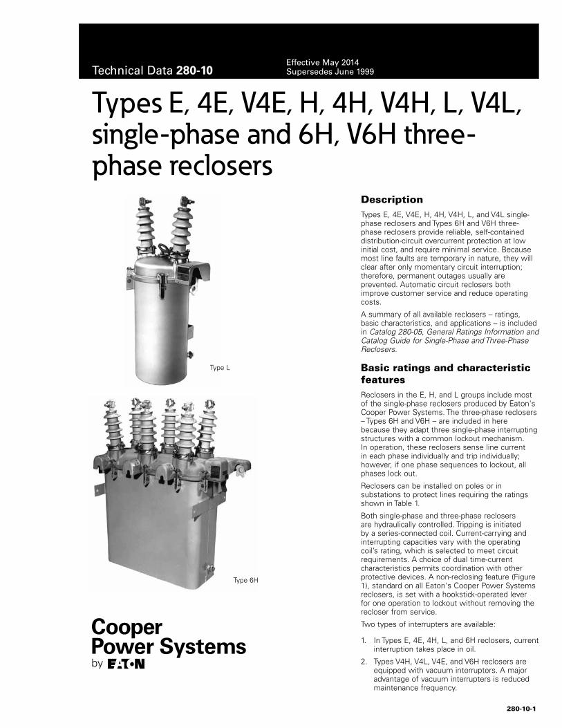
DescriptionTypes E, 4E, V4E, H, 4H, V4H, L, and V4L single-phase reclosers and Types 6H and V6H three-phase reclosers provide reliable, self-contained distribution-circuit overcurrent protection at low initial cost, and require minimal service. Because most line faults are temporary in nature, they will clear after only momentary circuit interruption; therefore, permanent outages usually are prevented. Automatic circuit reclosers both improve customer service and reduce operating costs.
A summary of all available reclosers – ratings, basic characteristics, and applications – is included in Catalog 280-05, General Ratings Information and Catalog Guide for Single-Phase and Three-Phase Reclosers.
Basic ratings and characteristic featuresReclosers in the E, H, and L groups include most of the single-phase reclosers produced by Eaton's Cooper Power Systems. The three-phase reclosers – Types 6H and V6H – are included in here because they adapt three single-phase interrupting structures with a common lockout mechanism. In operation, these reclosers sense line current in each phase individually and trip individually; however, if one phase sequences to lockout, all phases lock out.
Reclosers can be installed on poles or in substations to protect lines requiring the ratings shown in Table 1.
Both single-phase and three-phase reclosers are hydraulically controlled. Tripping is initiated by a series-connected coil. Current-carrying and interrupting capacities vary with the operating coil’s rating, which is selected to meet circuit requirements. A choice of dual time-current characteristics permits coordination with other protective devices. A non-reclosing feature (Figure 1), standard on all Eaton's Cooper Power Systems reclosers, is set with a hookstick-operated lever for one operation to lockout without removing the recloser from service.
Two types of interrupters are available:
1. In Types E, 4E, 4H, L, and 6H reclosers, current interruption takes place in oil.
2. Types V4H, V4L, V4E, and V6H reclosers are equipped with vacuum interrupters. A major advantage of vacuum interrupters is reduced maintenance frequency.
Types E, 4E, V4E, H, 4H, V4H, L, V4L, single-phase and 6H, V6H three-phase reclosers
Type L
Type 6H
280-10-1
Technical Data 280-10Effective May 2014Supersedes June 1999
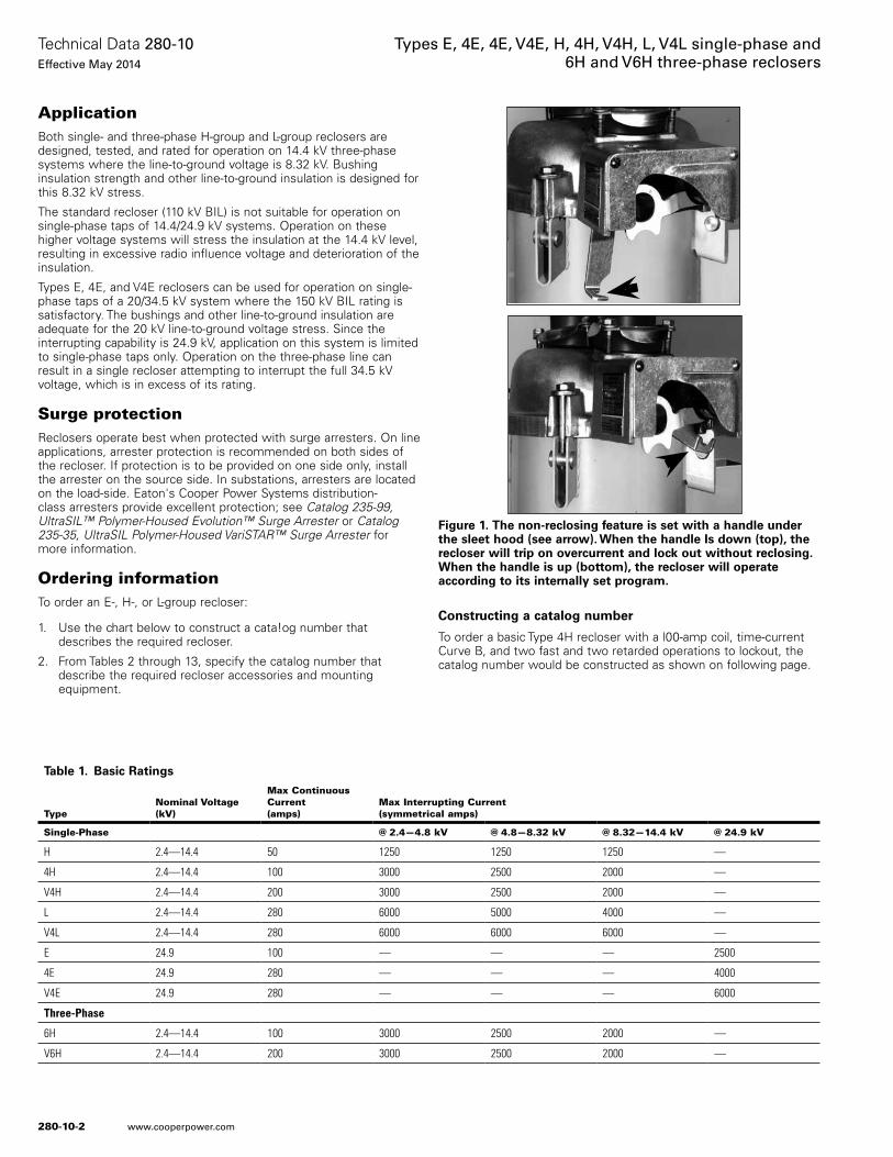
ApplicationBoth single- and three-phase H-group and L-group reclosers are designed, tested, and rated for operation on 14.4 kV three-phase systems where the line-to-ground voltage is 8.32 kV. Bushing insulation strength and other line-to-ground insulation is designed for this 8.32 kV stress.
The standard recloser (110 kV BIL) is not suitable for operation on single-phase taps of 14.4/24.9 kV systems. Operation on these higher voltage systems will stress the insulation at the 14.4 kV level, resulting in excessive radio influence voltage and deterioration of the insulation.
Types E, 4E, and V4E reclosers can be used for operation on single-phase taps of a 20/34.5 kV system where the 150 kV BIL rating is satisfactory. The bushings and other line-to-ground insulation are adequate for the 20 kV line-to-ground voltage stress. Since the interrupting capability is 24.9 kV, application on this system is limited to single-phase taps only. Operation on the three-phase line can result in a single recloser attempting to interrupt the full 34.5 kV voltage, which is in excess of its rating.
Surge protectionReclosers operate best when protected with surge arresters. On line applications, arrester protection is recommended on both sides of the recloser. If protection is to be provided on one side only, install the arrester on the source side. In substations, arresters are located on the load-side. Eaton's Cooper Power Systems distribution-class arresters provide excellent protection; see Catalog 235-99, UltraSIL™ Polymer-Housed Evolution™ Surge Arrester or Catalog 235-35, UltraSIL Polymer-Housed VariSTAR™ Surge Arrester for more information.
Ordering informationTo order an E-, H-, or L-group recloser:
1. Use the chart below to construct a cata!og number that describes the required recloser.
2. From Tables 2 through 13, specify the catalog number that describe the required recloser accessories and mounting equipment.
Constructing a catalog number
To order a basic Type 4H recloser with a l00-amp coil, time-current Curve B, and two fast and two retarded operations to lockout, the catalog number would be constructed as shown on following page.
Figure 1. The non-reclosing feature is set with a handle under the sleet hood (see arrow). When the handle Is down (top), the recloser will trip on overcurrent and lock out without reclosing. When the handle is up (bottom), the recloser will operate according to its internally set program.
Table 1. Basic Ratings
TypeNominal Voltage(kV)
Max ContinuousCurrent(amps)
Max Interrupting Current(symmetrical amps)
Single-Phase @ 2.4—4.8 kV @ 4.8—8.32 kV @ 8.32—14.4 kV @ 24.9 kV
H 2.4—14.4 50 1250 1250 1250 —
4H 2.4—14.4 100 3000 2500 2000 —
V4H 2.4—14.4 200 3000 2500 2000 —
L 2.4—14.4 280 6000 5000 4000 —
V4L 2.4—14.4 280 6000 6000 6000 —
E 24.9 100 — — — 2500
4E 24.9 280 — — — 4000
V4E 24.9 280 — — — 6000
Three-Phase
6H 2.4—14.4 100 3000 2500 2000 —
V6H 2.4—14.4 200 3000 2500 2000 —
280-10-2
Technical Data 280-10Effective May 2014
Types E, 4E, 4E, V4E, H, 4H, V4H, L, V4L single-phase and 6H and V6H three-phase reclosers
www.cooperpower.com
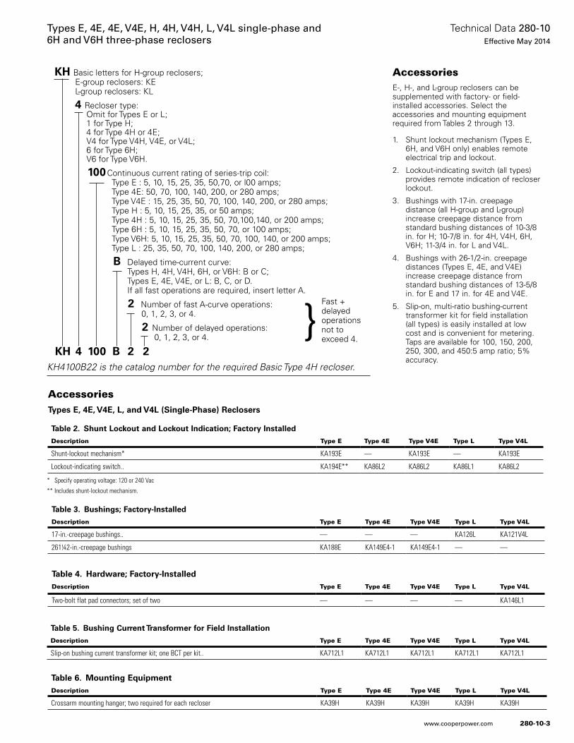
AccessoriesE-, H-, and L-group reclosers can be supplemented with factory- or field-installed accessories. Select the accessories and mounting equipment required from Tables 2 through 13.
1. Shunt lockout mechanism (Types E, 6H, and V6H only) enables remote electrical trip and lockout.
2. Lockout-indicating switch (all types) provides remote indication of recloser lockout.
3. Bushings with 17-in. creepage distance (all H-group and L-group) increase creepage distance from standard bushing distances of 10-3/8 in. for H; 10-7/8 in. for 4H, V4H, 6H, V6H; 11-3/4 in. for L and V4L.
4. Bushings with 26-1/2-in. creepage distances (Types E, 4E, and V4E) increase creepage distance from standard bushing distances of 13-5/8 in. for E and 17 in. for 4E and V4E.
5. Slip-on, multi-ratio bushing-current transformer kit for field installation (all types) is easily installed at low cost and is convenient for metering. Taps are available for 100, 150, 200, 250, 300, and 450:5 amp ratio; 5% accuracy.
KH Basic letters for H-group reclosers; E-group reclosers: KE L-group reclosers: KL
4 Recloser type: Omit for Types E or L; 1 for Type H; 4 for Type 4H or 4E; V4 for Type V4H, V4E, or V4L; 6 for Type 6H; V6 for Type V6H.
100 Continuous current rating of series-trip coil: Type E : 5, 10, 15, 25, 35, 50,70, or l00 amps; Type 4E: 50, 70, 100, 140, 200, or 280 amps; Type V4E : 15, 25, 35, 50, 70, 100, 140, 200, or 280 amps; Type H : 5, 10, 15, 25, 35, or 50 amps; Type 4H : 5, 10, 15, 25, 35, 50, 70,100,140, or 200 amps; Type 6H : 5, 10, 15, 25, 35, 50, 70, or 100 amps; Type V6H: 5, 10, 15, 25, 35, 50, 70, 100, 140, or 200 amps; Type L : 25, 35, 50, 70, 100, 140, 200, or 280 amps;
B Delayed time-current curve: Types H, 4H, V4H, 6H, or V6H: B or C; Types E, 4E, V4E, or L: B, C, or D. If all fast operations are required, insert letter A.
2 Number of fast A-curve operations: 0, 1, 2, 3, or 4.
2 Number of delayed operations: 0, 1, 2, 3, or 4.
KH 4 100 B 2 2KH4100B22 is the catalog number for the required Basic Type 4H recloser.
Fast + delayed operations not to exceed 4.}
Table 2. Shunt Lockout and Lockout Indication; Factory Installed
Description Type E Type 4E Type V4E Type L Type V4L
Shunt-lockout mechanism* KA193E — KA193E — KA193E
Lockout-indicating switch.. KA194E** KA86L2 KA86L2 KA86L1 KA86L2
* Specify operating voltage: 120 or 240 Vac
** Includes shunt-lockout mechanism.
AccessoriesTypes E, 4E, V4E, L, and V4L (Single-Phase) Reclosers
Table 3. Bushings; Factory-Installed
Description Type E Type 4E Type V4E Type L Type V4L
17-in.-creepage bushings.. — — — KA126L KA121V4L
261¼2-in.-creepage bushings KA188E KA149E4-1 KA149E4-1 — —
Table 5. Bushing Current Transformer for Field Installation
Description Type E Type 4E Type V4E Type L Type V4L
Slip-on bushing current transformer kit; one BCT per kit.. KA712L1 KA712L1 KA712L1 KA712L1 KA712L1
Table 6. Mounting EquipmentDescription Type E Type 4E Type V4E Type L Type V4L
Crossarm mounting hanger; two required for each recloser KA39H KA39H KA39H KA39H KA39H
Table 4. Hardware; Factory-InstalledDescription Type E Type 4E Type V4E Type L Type V4L
Two-bolt flat pad connectors; set of two — — — — KA146L1
280-10-3
Technical Data 280-10Effective May 2014
Types E, 4E, 4E, V4E, H, 4H, V4H, L, V4L single-phase and 6H and V6H three-phase reclosers
www.cooperpower.com
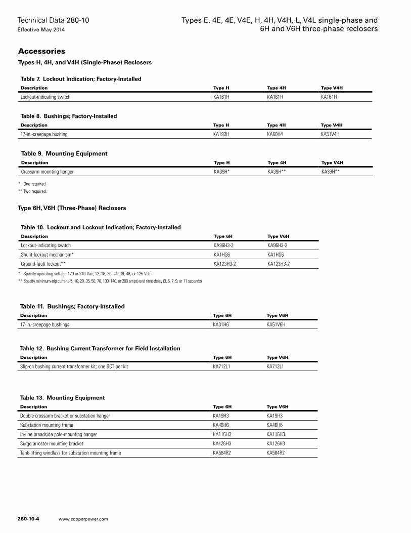
Table 7. Lockout Indication; Factory-Installed
Description Type H Type 4H Type V4H
Lockout-indicating switch KA161H KA161H KA161H
Table 8. Bushings; Factory-Installed
Description Type H Type 4H Type V4H
17-in.-creepage bushing KA193H KA60H4 KA51V4H
* One required.
** Two required.
Table 9. Mounting EquipmentDescription Type H Type 4H Type V4H
Crossarm mounting hanger KA39H* KA39H** KA39H**
* Specify operating voltage 120 or 240 Vac; 12, 18, 20, 24, 36, 48, or 125 Vdc.
** Specify minimum-trlp current (5, 10, 20, 35, 50, 70, 100, 140, or 200 amps) and time delay (3,.5, 7, 9, or 11 seconds)
Table 10. Lockout and Lockout Indication; Factory-Installed
Description Type 6H Type V6H
Lockout-indicating switch KA96H3-2 KA96H3-2
Shunt-lockout mechanism* KA1HS6 KA1HS6
Ground-fault lockout** KA123H3-2 KA123H3-2
Table 13. Mounting Equipment
Description Type 6H Type V6H
Double crossarm bracket or substation hanger KA19H3 KA19H3
Substation mounting frame KA46H6 KA46H6
In-line broadside pole-mounting hanger KA116H3 KA116H3
Surge arrester mounting bracket KA126H3 KA126H3
Tank-lifting windlass for substation mounting frame KA584R2 KA584R2
Table 11. Bushings; Factory-InstalledDescription Type 6H Type V6H
17-in.-creepage bushings KA31H6 KA51V6H
Table 12. Bushing Current Transformer for Field Installation
Description Type 6H Type V6H
Slip-on bushing current transformer kit; one BCT per kit KA712L1 KA712L1
AccessoriesTypes H, 4H, and V4H (Single-Phase) Reclosers
Type 6H, V6H (Three-Phase) Reclosers
280-10-4
Technical Data 280-10Effective May 2014
Types E, 4E, 4E, V4E, H, 4H, V4H, L, V4L single-phase and 6H and V6H three-phase reclosers
www.cooperpower.com
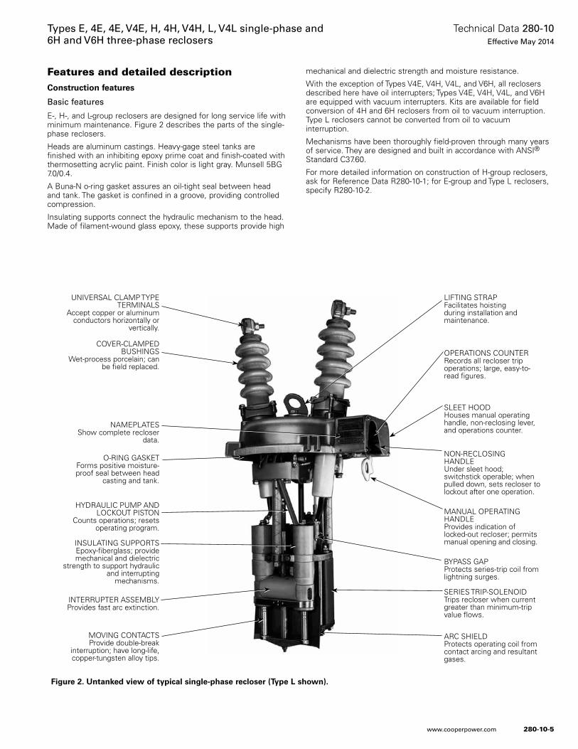
Features and detailed descriptionConstruction features
Basic features
E-, H-, and L-group reclosers are designed for long service life with minimum maintenance. Figure 2 describes the parts of the single-phase reclosers.
Heads are aluminum castings. Heavy-gage steel tanks are finished with an inhibiting epoxy prime coat and finish-coated with thermosetting acrylic paint. Finish color is light gray. Munsell 5BG 7.0/0.4.
A Buna-N o-ring gasket assures an oil-tight seal between head and tank. The gasket is confined in a groove, providing controlled compression.
Insulating supports connect the hydraulic mechanism to the head. Made of filament-wound glass epoxy, these supports provide high
mechanical and dielectric strength and moisture resistance.
With the exception of Types V4E, V4H, V4L, and V6H, all reclosers described here have oil interrupters; Types V4E, V4H, V4L, and V6H are equipped with vacuum interrupters. Kits are available for field conversion of 4H and 6H reclosers from oil to vacuum interruption. Type L reclosers cannot be converted from oil to vacuum interruption.
Mechanisms have been thoroughly field-proven through many years of service. They are designed and built in accordance with ANSI® Standard C37.60.
For more detailed information on construction of H-group reclosers, ask for Reference Data R280-10-1; for E-group and Type L reclosers, specify R280-10-2.
Figure 2. Untanked view of typical single-phase recloser (Type L shown).
UNIVERSAL CLAMP TYPE TERMINALS
Accept copper or aluminum conductors horizontally or
vertically.
COVER-CLAMPED BUSHINGS
Wet-process porcelain; can be field replaced.
NAMEPLATES Show complete recloser
data.
O-RING GASKETForms positive moisture-proof seal between head
casting and tank.
HYDRAULIC PUMP AND LOCKOUT PISTON
Counts operations; resets operating program.
INSULATING SUPPORTSEpoxy-fiberglass; provide mechanical and dielectric
strength to support hydraulic and interrupting
mechanisms.
INTERRUPTER ASSEMBLYProvides fast arc extinction.
MOVING CONTACTSProvide double-break
interruption; have long-life, copper-tungsten alloy tips.
LIFTING STRAPFacilitates hoisting during installation and maintenance.
OPERATIONS COUNTERRecords all recloser trip operations; large, easy-to-read figures.
SLEET HOODHouses manual operating handle, non-reclosing lever, and operations counter.
NON-RECLOSING HANDLEUnder sleet hood; switchstick operable; when pulled down, sets recloser to lockout after one operation.
MANUAL OPERATING HANDLEProvides indication of locked-out recloser; permits manual opening and closing.
BYPASS GAPProtects series-trip coil from lightning surges.
SERIES TRIP-SOLENOIDTrips recloser when current greater than minimum-trip value flows.
ARC SHIELDProtects operating coil from contact arcing and resultant gases.
280-10-5
Technical Data 280-10Effective May 2014
Types E, 4E, 4E, V4E, H, 4H, V4H, L, V4L single-phase and 6H and V6H three-phase reclosers
www.cooperpower.com
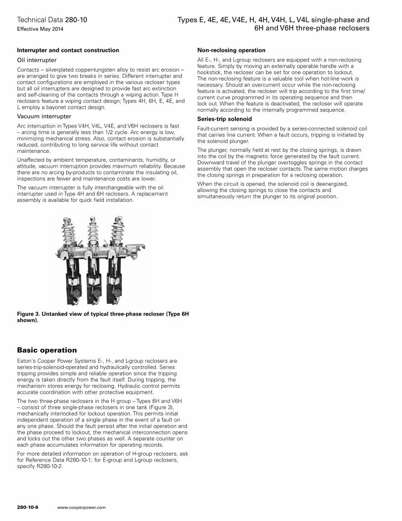
Interrupter and contact construction
Oil interrupter
Contacts – silverplated copper-tungsten alloy to resist arc erosion – are arranged to give two breaks in series. Different interrupter and contact configurations are employed in the various recloser types but all oil interrupters are designed to provide fast arc extinction and self-cleaning of the contacts through a wiping action. Type H reclosers feature a wiping contact design; Types 4H, 6H, E, 4E, and L employ a bayonet contact design.
Vacuum interrupter
Arc interruption in Types V4H, V4L, V4E, and V6H reclosers is fast – arcing time is generally less than 1/2 cycle. Arc energy is low, minimizing mechanical stress. Also, contact erosion is substantially reduced, contributing to long service life without contact maintenance.
Unaffected by ambient temperature, contaminants, humidity, or altitude, vacuum interruption provides maximum reliability. Because there are no arcing by-products to contaminate the insulating oil, inspections are fewer and maintenance costs are lower.
The vacuum interrupter is fully interchangeable with the oil interrupter used in Type 4H and 6H reclosers. A replacement assembly is available for quick field installation.
Basic operationEaton's Cooper Power Systems E-, H-, and L-group reclosers are series-trip-solenoid-operated and hydraulically controlled. Series tripping provides simple and reliable operation since the tripping energy is taken directly from the fault itself. During tripping, the mechanism stores energy for reclosing. Hydraulic control permits accurate coordination with other protective equipment.
The two three-phase reclosers in the H group – Types 6H and V6H – consist of three single-phase reclosers in one tank (Figure 3), mechanically interlocked for lockout operation. This permits initial independent operation of a single phase in the event of a fault on any one phase. Should the fault persist after the initial operation and the phase proceed to lockout, the mechanical interconnection opens and locks out the other two phases as well. A separate counter on each phase accumulates information for operating records.
For more detailed information on operation of H-group reclosers, ask for Reference Data R280-10-1; for E-group and L-group reclosers, specify R280-10-2.
Non-reclosing operation
All E-, H-, and L-group reclosers are equipped with a non-reclosing feature. Simply by moving an externally operable handle with a hookstick, the recloser can be set for one operation to lockout. The non-reclosing feature is a valuable tool when hot-line work is necessary. Should an overcurrent occur while the non-reclosing feature is activated, the recloser will trip according to the first time/current curve programmed in its operating sequence and then lock out. When the feature is deactivated, the recloser will operate normally according to the internally programmed sequence.
Series-trip solenoid
Fault-current sensing is provided by a series-connected solenoid coil that carries line current. When a fault occurs, tripping is initiated by the solenoid plunger.
The plunger, normally held at rest by the closing springs, is drawn into the coil by the magnetic force generated by the fault current. Downward travel of the plunger overtoggles springs in the contact assembly that open the recloser contacts. The same motion charges the closing springs in preparation for a reclosing operation.
When the circuit is opened, the solenoid coil is deenergized, allowing the closing springs to close the contacts and simultaneously return the plunger to its original position.
Figure 3. Untanked view of typical three-phase recloser (Type 6H shown).
280-10-6
Technical Data 280-10Effective May 2014
Types E, 4E, 4E, V4E, H, 4H, V4H, L, V4L single-phase and 6H and V6H three-phase reclosers
www.cooperpower.com
Contact operating speeds – controlled entirely by the springs – are independent of the magnitude of the fault current. Total time to contact opening is proportional to the level of fault current passing through the series-trip solenoid.
When the recloser operates to lockout, the hydraulic mechanism releases a lock-out spring and mechanism, preventing the plunger from returning and the contacts from reclosing.
The series-trip coil is capable of withstanding forces caused by maximum-rated fault currents and is effectively shunted with a bypass gap for surge protection.
Hydraulic control mechanism
The hydraulic control mechanism provides selectivity in timing enabling flexibility in application and coordination with other equipment. All timing is governed by the hydraulic mechanism which:
1. controls the timing before contact opening;
2. establishes the time delay before the contacts reclose;
3. counts the number of operations;
4. causes the recloser to lock out when the preset number of trip operations has been completed.
Variations of timing characteristics and sequences can be programmed for a maximum of four operations. When a recloser is programmed for both fast and retarded operations, the fast operations – involving no intentional time delay – occur first in the sequence according to the recloser’s A curve time-current characteristic. Retarded operations are according to the recloser’s B or C time-current curve (B, C, or D curve for Types E, 4E, and L). See Time Current Curves R280-91-10 for Type E reclosers; R280-91-8 for Type 4E; R280-91-1 for Type H; R280-91-2 for Types 4H, V4H, 6H, and V6H; R280-91-3 for Type L; and R280-91-15 for Types V4L and V4E.
280-10-7
Technical Data 280-10Effective May 2014
Types E, 4E, 4E, V4E, H, 4H, V4H, L, V4L single-phase and 6H and V6H three-phase reclosers
www.cooperpower.com
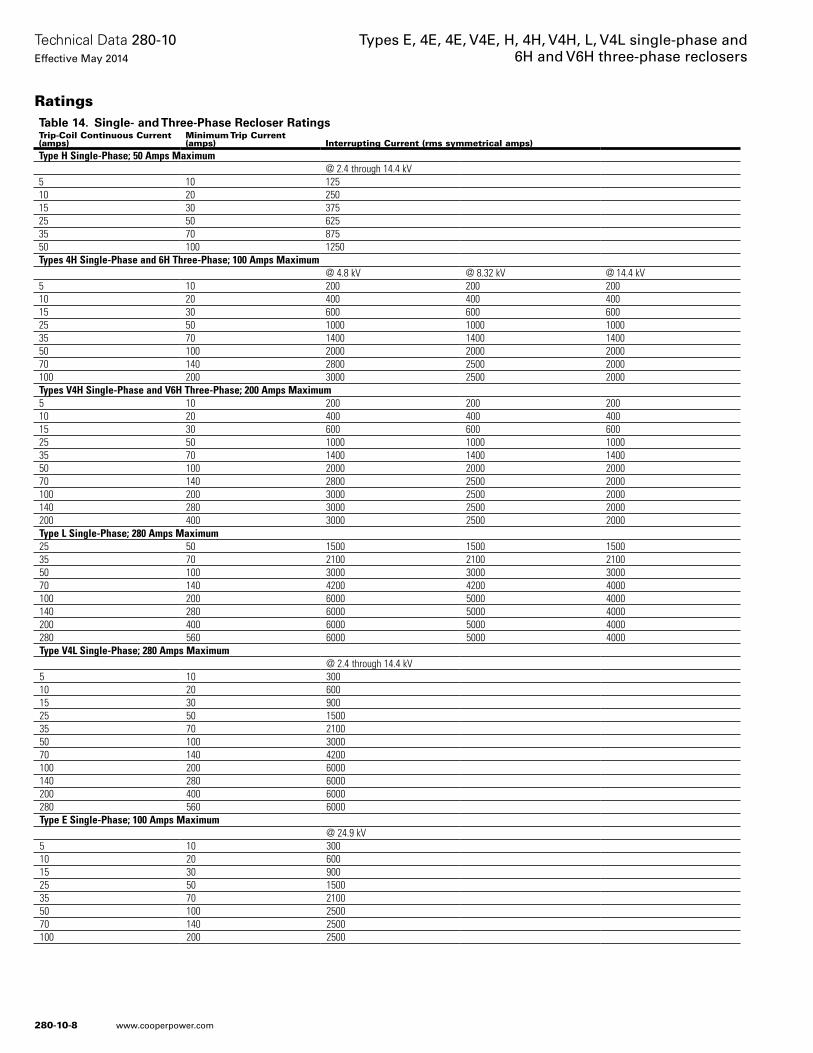
RatingsTable 14. Single- and Three-Phase Recloser RatingsTrip-Coil Continuous Current(amps)
Minimum Trip Current(amps) Interrupting Current (rms symmetrical amps)
Type H Single-Phase; 50 Amps Maximum@ 2.4 through 14.4 kV
5 10 12510 20 25015 30 37525 50 62535 70 87550 100 1250Types 4H Single-Phase and 6H Three-Phase; 100 Amps Maximum
@ 4.8 kV @ 8.32 kV @ 14.4 kV5 10 200 200 20010 20 400 400 40015 30 600 600 60025 50 1000 1000 100035 70 1400 1400 140050 100 2000 2000 200070 140 2800 2500 2000100 200 3000 2500 2000Types V4H Single-Phase and V6H Three-Phase; 200 Amps Maximum5 10 200 200 20010 20 400 400 40015 30 600 600 60025 50 1000 1000 100035 70 1400 1400 140050 100 2000 2000 200070 140 2800 2500 2000100 200 3000 2500 2000140 280 3000 2500 2000200 400 3000 2500 2000Type L Single-Phase; 280 Amps Maximum25 50 1500 1500 150035 70 2100 2100 210050 100 3000 3000 300070 140 4200 4200 4000100 200 6000 5000 4000140 280 6000 5000 4000200 400 6000 5000 4000280 560 6000 5000 4000Type V4L Single-Phase; 280 Amps Maximum
@ 2.4 through 14.4 kV5 10 30010 20 60015 30 90025 50 150035 70 210050 100 300070 140 4200100 200 6000140 280 6000200 400 6000280 560 6000Type E Single-Phase; 100 Amps Maximum
@ 24.9 kV5 10 30010 20 60015 30 90025 50 150035 70 210050 100 250070 140 2500100 200 2500
280-10-8
Technical Data 280-10Effective May 2014
Types E, 4E, 4E, V4E, H, 4H, V4H, L, V4L single-phase and 6H and V6H three-phase reclosers
www.cooperpower.com
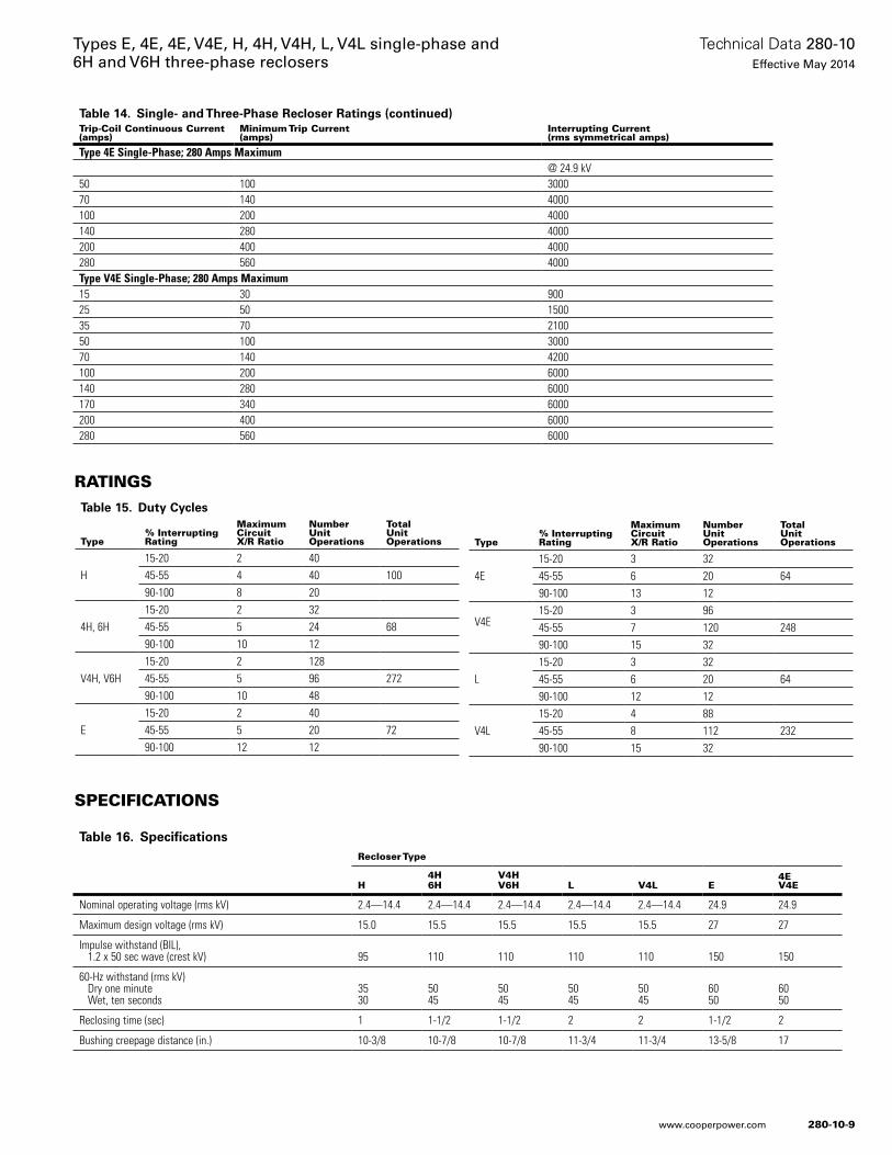
Type% InterruptingRating
MaximumCircuitX/R Ratio
NumberUnitOperations
TotalUnitOperations
4E15-20 3 3245-55 6 20 6490-100 13 12
V4E15-20 3 9645-55 7 120 24890-100 15 32
L15-20 3 3245-55 6 20 6490-100 12 12
V4L15-20 4 8845-55 8 112 23290-100 15 32
Table 15. Duty Cycles
Type% InterruptingRating
MaximumCircuitX/R Ratio
NumberUnitOperations
TotalUnitOperations
H15-20 2 4045-55 4 40 10090-100 8 20
4H, 6H15-20 2 3245-55 5 24 6890-100 10 12
V4H, V6H15-20 2 12845-55 5 96 27290-100 10 48
E15-20 2 4045-55 5 20 7290-100 12 12
Table 14. Single- and Three-Phase Recloser Ratings (continued)Trip-Coil Continuous Current(amps)
Minimum Trip Current(amps)
Interrupting Current (rms symmetrical amps)
Type 4E Single-Phase; 280 Amps Maximum@ 24.9 kV
50 100 300070 140 4000100 200 4000140 280 4000200 400 4000280 560 4000Type V4E Single-Phase; 280 Amps Maximum15 30 90025 50 150035 70 210050 100 300070 140 4200100 200 6000140 280 6000170 340 6000200 400 6000280 560 6000
RATINGS
SPECIFICATIONS
Table 16. SpecificationsRecloser Type
H4H6H
V4HV6H L V4L E
4EV4E
Nominal operating voltage (rms kV) 2.4—14.4 2.4—14.4 2.4—14.4 2.4—14.4 2.4—14.4 24.9 24.9
Maximum design voltage (rms kV) 15.0 15.5 15.5 15.5 15.5 27 27
Impulse withstand (BIL), 1.2 x 50 sec wave (crest kV) 95 110 110 110 110 150 150
60-Hz withstand (rms kV) Dry one minute Wet, ten seconds
3530
5045
5045
5045
5045
6050
6050
Reclosing time (sec) 1 1-1/2 1-1/2 2 2 1-1/2 2
Bushing creepage distance (in.) 10-3/8 10-7/8 10-7/8 11-3/4 11-3/4 13-5/8 17
280-10-9
Technical Data 280-10Effective May 2014
Types E, 4E, 4E, V4E, H, 4H, V4H, L, V4L single-phase and 6H and V6H three-phase reclosers
www.cooperpower.com
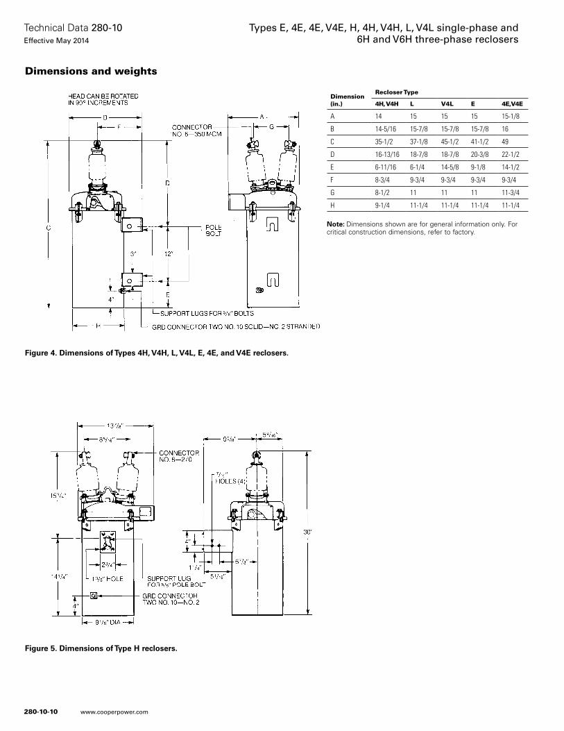
Dimensions and weights
Dimension(in.)
Recloser Type
4H, V4H L V4L E 4E,V4E
A 14 15 15 15 15-1/8
B 14-5/16 15-7/8 15-7/8 15-7/8 16
C 35-1/2 37-1/8 45-1/2 41-1/2 49
D 16-13/16 18-7/8 18-7/8 20-3/8 22-1/2
E 6-11/16 6-1/4 14-5/8 9-1/8 14-1/2
F 8-3/4 9-3/4 9-3/4 9-3/4 9-3/4
G 8-1/2 11 11 11 11-3/4
H 9-1/4 11-1/4 11-1/4 11-1/4 11-1/4
otee:N Dimensions shown are for general information only. For critical construction dimensions, refer to factory.
Figure 4. Dimensions of Types 4H, V4H, L, V4L, E, 4E, and V4E reclosers.
Figure 5. Dimensions of Type H reclosers.
280-10-10
Technical Data 280-10Effective May 2014
Types E, 4E, 4E, V4E, H, 4H, V4H, L, V4L single-phase and 6H and V6H three-phase reclosers
www.cooperpower.com
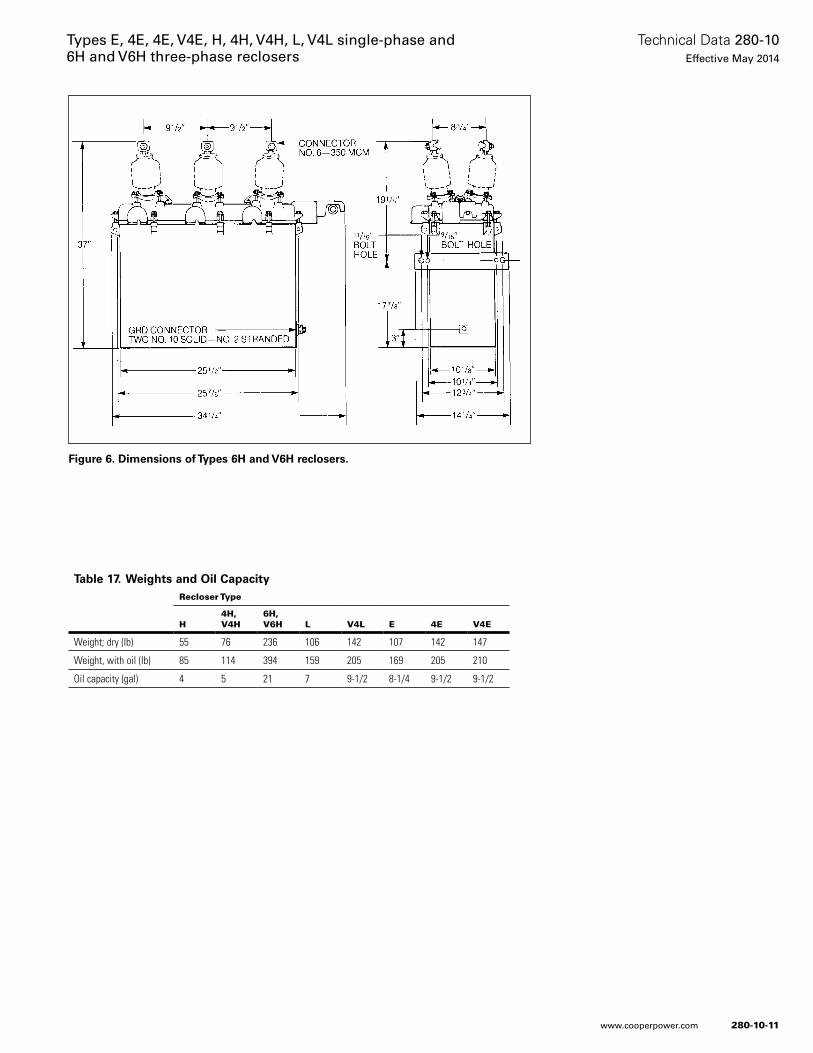
Dimension(in.)
Recloser Type
4H, V4H L V4L E 4E,V4E
A 14 15 15 15 15-1/8
B 14-5/16 15-7/8 15-7/8 15-7/8 16
C 35-1/2 37-1/8 45-1/2 41-1/2 49
D 16-13/16 18-7/8 18-7/8 20-3/8 22-1/2
E 6-11/16 6-1/4 14-5/8 9-1/8 14-1/2
F 8-3/4 9-3/4 9-3/4 9-3/4 9-3/4
G 8-1/2 11 11 11 11-3/4
H 9-1/4 11-1/4 11-1/4 11-1/4 11-1/4
Figure 6. Dimensions of Types 6H and V6H reclosers.
Table 17. Weights and Oil CapacityRecloser Type
H4H,V4H
6H,V6H L V4L E 4E V4E
Weight; dry (Ib) 55 76 236 106 142 107 142 147
Weight, with oil (Ib) 85 114 394 159 205 169 205 210
Oil capacity (gal) 4 5 21 7 9-1/2 8-1/4 9-1/2 9-1/2
280-10-11
Technical Data 280-10Effective May 2014
Types E, 4E, 4E, V4E, H, 4H, V4H, L, V4L single-phase and 6H and V6H three-phase reclosers
www.cooperpower.com
Eaton, Cooper Power Systems, VariSTAR, UltraSIL, and Evolution are valuable trademarks of Eaton in the U.S. and other countries. You are not permitted to use the these trademarks without the prior written consent of Eaton.ANSI® is a registered trademark of American National Standards Institute.
Types E, 4E, 4E, V4E, H, 4H, V4H, L, V4L single-phase and 6H and V6H three-phase reclosers
Eaton1000 Eaton BoulevardCleveland, OH 44122United StatesEaton.com
Eaton’s Cooper Power Systems Business2300 Badger DriveWaukesha, WI 53188United StatesCooperpower.com
© 2014 EatonAll Rights ReservedPrinted in USAPublication No. 280-10May 2014
Technical Data 280-10Effective May 2014
For Eaton’s Cooper Power Systems reclosers product information call 1-877-277-4636 or visit: www.cooperpower.com.
280-10-12
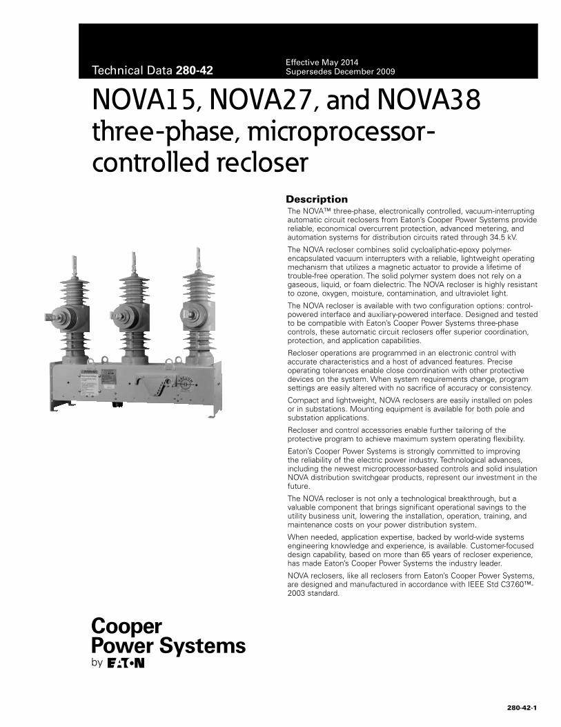
The NOVA™ three-phase, electronically controlled, vacuum-interrupting automatic circuit reclosers from Eaton’s Cooper Power Systems provide reliable, economical overcurrent protection, advanced metering, and automation systems for distribution circuits rated through 34.5 kV.
The NOVA recloser combines solid cycloaliphatic-epoxy polymer-encapsulated vacuum interrupters with a reliable, lightweight operating mechanism that utilizes a magnetic actuator to provide a lifetime of trouble-free operation. The solid polymer system does not rely on a gaseous, liquid, or foam dielectric. The NOVA recloser is highly resistant to ozone, oxygen, moisture, contamination, and ultraviolet light.
The NOVA recloser is available with two configuration options: control-powered interface and auxiliary-powered interface. Designed and tested to be compatible with Eaton’s Cooper Power Systems three-phase controls, these automatic circuit reclosers offer superior coordination, protection, and application capabilities.
Recloser operations are programmed in an electronic control with accurate characteristics and a host of advanced features. Precise operating tolerances enable close coordination with other protective devices on the system. When system requirements change, program settings are easily altered with no sacrifice of accuracy or consistency.
Compact and lightweight, NOVA reclosers are easily installed on poles or in substations. Mounting equipment is available for both pole and substation applications.
Recloser and control accessories enable further tailoring of the protective program to achieve maximum system operating flexibility.
Eaton’s Cooper Power Systems is strongly committed to improving the reliability of the electric power industry. Technological advances, including the newest microprocessor-based controls and solid insulation NOVA distribution switchgear products, represent our investment in the future.
The NOVA recloser is not only a technological breakthrough, but a valuable component that brings significant operational savings to the utility business unit, lowering the installation, operation, training, and maintenance costs on your power distribution system.
When needed, application expertise, backed by world-wide systems engineering knowledge and experience, is available. Customer-focused design capability, based on more than 65 years of recloser experience, has made Eaton’s Cooper Power Systems the industry leader.
NOVA reclosers, like all reclosers from Eaton’s Cooper Power Systems, are designed and manufactured in accordance with IEEE Std C37.60™-2003 standard.
NOVA15, NOVA27, and NOVA38 three-phase, microprocessor- controlled recloser
Description
280-42-1
Technical Data 280-42Effective May 2014Supersedes December 2009
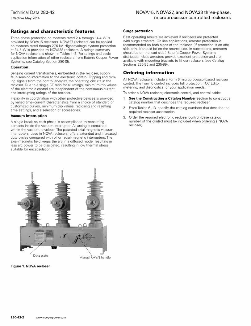
Ratings and characteristic featuresThree-phase protection on systems rated 2.4 through 14.4 kV is provided by NOVA15 reclosers. NOVA27 reclosers can be applied on systems rated through 27.6 kV. Higher-voltage system protection at 34.5 kV is provided by NOVA38 reclosers. A ratings summary for NOVA reclosers is shown in Tables 1–3. For ratings and basic application information of other reclosers from Eaton’s Cooper Power Systems, see Catalog Section 280-05.
Operation
Sensing current transformers, embedded in the recloser, supply fault-sensing information to the electronic control. Tripping and clos-ing signals from the control energize the operating circuits in the recloser. Due to a single CT ratio for all ratings, minimum-trip values of the electronic control are independent of the continuous-current and interrupting ratings of the recloser.
Flexibility in coordination with other protective devices is provided by varied time–current characteristics from a choice of standard or customized curves, minimum trip values, reclosing and resetting time settings, and a selection of accessories.
Vacuum interruption
A single break on each phase is accomplished by separating contacts inside the vacuum interrupter. All arcing is contained within the vacuum envelope. The patented axial-magnetic vacuum interrupters, used in NOVA reclosers, offers extended and increased duty cycles compared with oil or radial-magnetic interrupters. The axial-magnetic field keeps the arc in a diffused mode, resulting in less arc power to be dissipated, resulting in low thermal stress, suitable for encapsulation.
Surge protection
Best operating results are achieved if reclosers are protected with surge arresters. On line applications, arrester protection is recommended on both sides of the recloser. (If protection is on one side only, it should be on the source side. In substations, arresters should be on the load side.) Eaton’s Cooper Power Systems distribution-class arresters provide excellent protection and are available with mounting brackets to fit our reclosers (see Catalog Sections 235-35 and 235-99).
Ordering informationAll NOVA reclosers include a Form 6 microprocessor-based recloser control. The Form 6 control includes full protection, TCC Editor, metering, and diagnostics for your application needs.
To order a NOVA recloser, electronic control, and control cable:
1. See the Constructing a Catalog Number section to construct a catalog number that describes the required recloser.
2. From Tables 6–13, specify the catalog numbers that describe the required recloser accessories.
3. Order the required electronic recloser control (Base catalog number of the control must be included when ordering a NOVA recloser).
Figure 1. NOVA recloser.
Manual OPEN handleData plate
280-42-2
Technical Data 280-42Effective May 2014
NOVA15, NOVA27, and NOVA38 three-phase, microprocessor-controlled reclosers
www.cooperpower.com
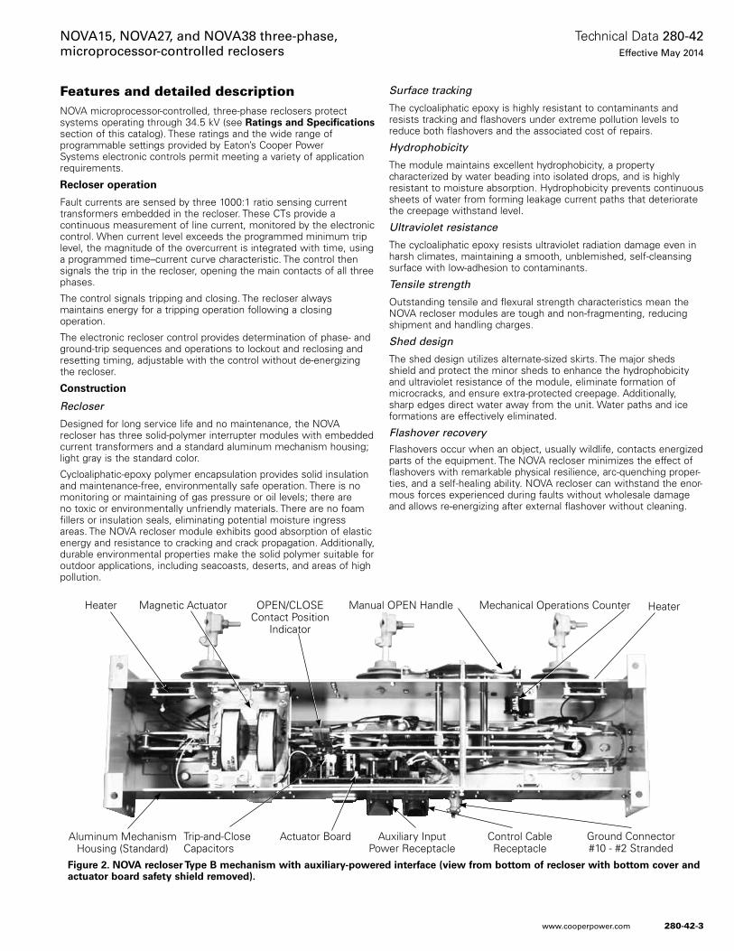
Features and detailed descriptionNOVA microprocessor-controlled, three-phase reclosers protect systems operating through 34.5 kV (see Ratings and Specifications section of this catalog). These ratings and the wide range of programmable settings provided by Eaton’s Cooper Power Systems electronic controls permit meeting a variety of application requirements.
Recloser operation
Fault currents are sensed by three 1000:1 ratio sensing current transformers embedded in the recloser. These CTs provide a continuous measurement of line current, monitored by the electronic control. When current level exceeds the programmed minimum trip level, the magnitude of the overcurrent is integrated with time, using a programmed time–current curve characteristic. The control then signals the trip in the recloser, opening the main contacts of all three phases.
The control signals tripping and closing. The recloser always maintains energy for a tripping operation following a closing operation.
The electronic recloser control provides determination of phase- and ground-trip sequences and operations to lockout and reclosing and resetting timing, adjustable with the control without de-energizing the recloser.
Construction
Recloser
Designed for long service life and no maintenance, the NOVA recloser has three solid-polymer interrupter modules with embedded current transformers and a standard aluminum mechanism housing; light gray is the standard color.
Cycloaliphatic-epoxy polymer encapsulation provides solid insulation and maintenance-free, environmentally safe operation. There is no monitoring or maintaining of gas pressure or oil levels; there are no toxic or environmentally unfriendly materials. There are no foam fillers or insulation seals, eliminating potential moisture ingress areas. The NOVA recloser module exhibits good absorption of elastic energy and resistance to cracking and crack propagation. Additionally, durable environmental properties make the solid polymer suitable for outdoor applications, including seacoasts, deserts, and areas of high pollution.
Surface tracking
The cycloaliphatic epoxy is highly resistant to contaminants and resists tracking and flashovers under extreme pollution levels to reduce both flashovers and the associated cost of repairs.
Hydrophobicity
The module maintains excellent hydrophobicity, a property characterized by water beading into isolated drops, and is highly resistant to moisture absorption. Hydrophobicity prevents continuous sheets of water from forming leakage current paths that deteriorate the creepage withstand level.
Ultraviolet resistance
The cycloaliphatic epoxy resists ultraviolet radiation damage even in harsh climates, maintaining a smooth, unblemished, self-cleansing surface with low-adhesion to contaminants.
Tensile strength
Outstanding tensile and flexural strength characteristics mean the NOVA recloser modules are tough and non-fragmenting, reducing shipment and handling charges.
Shed design
The shed design utilizes alternate-sized skirts. The major sheds shield and protect the minor sheds to enhance the hydrophobicity and ultraviolet resistance of the module, eliminate formation of microcracks, and ensure extra-protected creepage. Additionally, sharp edges direct water away from the unit. Water paths and ice formations are effectively eliminated.
Flashover recoveryFlashovers occur when an object, usually wildlife, contacts energized parts of the equipment. The NOVA recloser minimizes the effect of flashovers with remarkable physical resilience, arc-quenching proper-ties, and a self-healing ability. NOVA recloser can withstand the enor-mous forces experienced during faults without wholesale damage and allows re-energizing after external flashover without cleaning.
Figure 2. NOVA recloser Type B mechanism with auxiliary-powered interface (view from bottom of recloser with bottom cover and actuator board safety shield removed).
Manual OPEN Handle Mechanical Operations CounterOPEN/CLOSEContact Position
Indicator
Heater Magnetic Actuator
Trip-and-Close Capacitors
Actuator Board Auxiliary Input Power Receptacle
Ground Connector#10 - #2 Stranded
Control Cable Receptacle
Aluminum Mechanism Housing (Standard)
Heater
280-42-3
Technical Data 280-42Effective May 2014
NOVA15, NOVA27, and NOVA38 three-phase, microprocessor-controlled reclosers
www.cooperpower.com
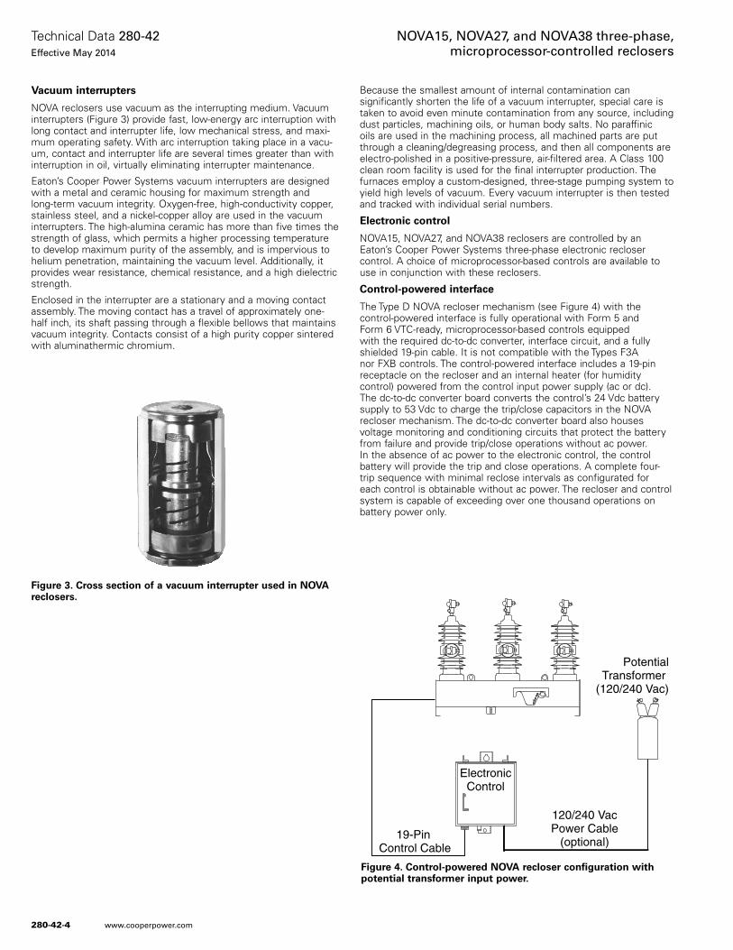
Vacuum interrupters
NOVA reclosers use vacuum as the interrupting medium. Vacuum interrupters (Figure 3) provide fast, low-energy arc interruption with long contact and interrupter life, low mechanical stress, and maxi-mum operating safety. With arc interruption taking place in a vacu-um, contact and interrupter life are several times greater than with interruption in oil, virtually eliminating interrupter maintenance.
Eaton’s Cooper Power Systems vacuum interrupters are designed with a metal and ceramic housing for maximum strength and long-term vacuum integrity. Oxygen-free, high-conductivity copper, stainless steel, and a nickel-copper alloy are used in the vacuum interrupters. The high-alumina ceramic has more than five times the strength of glass, which permits a higher processing temperature to develop maximum purity of the assembly, and is impervious to helium penetration, maintaining the vacuum level. Additionally, it provides wear resistance, chemical resistance, and a high dielectric strength.
Enclosed in the interrupter are a stationary and a moving contact assembly. The moving contact has a travel of approximately one-half inch, its shaft passing through a flexible bellows that maintains vacuum integrity. Contacts consist of a high purity copper sintered with aluminathermic chromium.
Because the smallest amount of internal contamination can significantly shorten the life of a vacuum interrupter, special care is taken to avoid even minute contamination from any source, including dust particles, machining oils, or human body salts. No paraffinic oils are used in the machining process, all machined parts are put through a cleaning/degreasing process, and then all components are electro-polished in a positive-pressure, air-filtered area. A Class 100 clean room facility is used for the final interrupter production. The furnaces employ a custom-designed, three-stage pumping system to yield high levels of vacuum. Every vacuum interrupter is then tested and tracked with individual serial numbers.
Electronic control
NOVA15, NOVA27, and NOVA38 reclosers are controlled by an Eaton’s Cooper Power Systems three-phase electronic recloser control. A choice of microprocessor-based controls are available to use in conjunction with these reclosers.
Control-powered interface
The Type D NOVA recloser mechanism (see Figure 4) with the control-powered interface is fully operational with Form 5 and Form 6 VTC-ready, microprocessor-based controls equipped with the required dc-to-dc converter, interface circuit, and a fully shielded 19-pin cable. It is not compatible with the Types F3A nor FXB controls. The control-powered interface includes a 19-pin receptacle on the recloser and an internal heater (for humidity control) powered from the control input power supply (ac or dc). The dc-to-dc converter board converts the control’s 24 Vdc battery supply to 53 Vdc to charge the trip/close capacitors in the NOVA recloser mechanism. The dc-to-dc converter board also houses voltage monitoring and conditioning circuits that protect the battery from failure and provide trip/close operations without ac power. In the absence of ac power to the electronic control, the control battery will provide the trip and close operations. A complete four-trip sequence with minimal reclose intervals as configurated for each control is obtainable without ac power. The recloser and control system is capable of exceeding over one thousand operations on battery power only.
ElectronicControl
PotentialTransformer
(120/240 Vac)
120/240 VacPower Cable
(optional)19-Pin
Control Cable
OP
EN
CLOSED
Figure 4. Control-powered NOVA recloser configuration with potential transformer input power.
Figure 3. Cross section of a vacuum interrupter used in NOVA reclosers.
280-42-4
Technical Data 280-42Effective May 2014
NOVA15, NOVA27, and NOVA38 three-phase, microprocessor-controlled reclosers
www.cooperpower.com
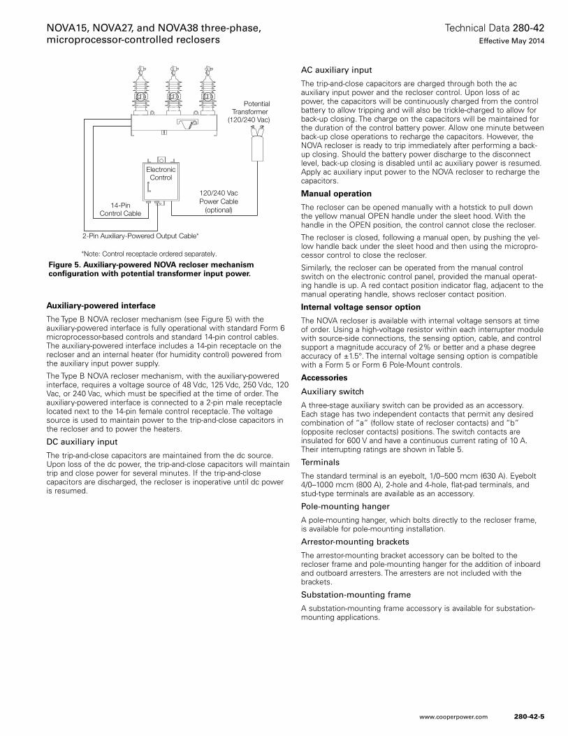
Auxiliary-powered interface
The Type B NOVA recloser mechanism (see Figure 5) with the auxiliary-powered interface is fully operational with standard Form 6 microprocessor-based controls and standard 14-pin control cables. The auxiliary-powered interface includes a 14-pin receptacle on the recloser and an internal heater (for humidity control) powered from the auxiliary input power supply.
The Type B NOVA recloser mechanism, with the auxiliary-powered interface, requires a voltage source of 48 Vdc, 125 Vdc, 250 Vdc, 120 Vac, or 240 Vac, which must be specified at the time of order. The auxiliary-powered interface is connected to a 2-pin male receptacle located next to the 14-pin female control receptacle. The voltage source is used to maintain power to the trip-and-close capacitors in the recloser and to power the heaters.
DC auxiliary input
The trip-and-close capacitors are maintained from the dc source. Upon loss of the dc power, the trip-and-close capacitors will maintain trip and close power for several minutes. If the trip-and-close capacitors are discharged, the recloser is inoperative until dc power is resumed.
AC auxiliary input
The trip-and-close capacitors are charged through both the ac auxiliary input power and the recloser control. Upon loss of ac power, the capacitors will be continuously charged from the control battery to allow tripping and will also be trickle-charged to allow for back-up closing. The charge on the capacitors will be maintained for the duration of the control battery power. Allow one minute between back-up close operations to recharge the capacitors. However, the NOVA recloser is ready to trip immediately after performing a back-up closing. Should the battery power discharge to the disconnect level, back-up closing is disabled until ac auxiliary power is resumed. Apply ac auxiliary input power to the NOVA recloser to recharge the capacitors.
Manual operation
The recloser can be opened manually with a hotstick to pull down the yellow manual OPEN handle under the sleet hood. With the handle in the OPEN position, the control cannot close the recloser.
The recloser is closed, following a manual open, by pushing the yel-low handle back under the sleet hood and then using the micropro-cessor control to close the recloser.
Similarly, the recloser can be operated from the manual control switch on the electronic control panel, provided the manual operat-ing handle is up. A red contact position indicator flag, adjacent to the manual operating handle, shows recloser contact position.
Internal voltage sensor option
The NOVA recloser is available with internal voltage sensors at time of order. Using a high-voltage resistor within each interrupter module with source-side connections, the sensing option, cable, and control support a magnitude accuracy of 2% or better and a phase degree accuracy of ±1.5°. The internal voltage sensing option is compatible with a Form 5 or Form 6 Pole-Mount controls.
Accessories
Auxiliary switch
A three-stage auxiliary switch can be provided as an accessory. Each stage has two independent contacts that permit any desired combination of “a” (follow state of recloser contacts) and “b” (opposite recloser contacts) positions. The switch contacts are insulated for 600 V and have a continuous current rating of 10 A. Their interrupting ratings are shown in Table 5.
Terminals
The standard terminal is an eyebolt, 1/0–500 mcm (630 A). Eyebolt 4/0–1000 mcm (800 A), 2-hole and 4-hole, flat-pad terminals, and stud-type terminals are available as an accessory.
Pole-mounting hanger
A pole-mounting hanger, which bolts directly to the recloser frame, is available for pole-mounting installation.
Arrestor-mounting brackets
The arrestor-mounting bracket accessory can be bolted to the recloser frame and pole-mounting hanger for the addition of inboard and outboard arresters. The arresters are not included with the brackets.
Substation-mounting frame
A substation-mounting frame accessory is available for substation-mounting applications.
ElectronicControl
120/240 VacPower Cable
(optional)14-Pin
Control Cable
OP
EN
2-Pin Auxiliary-Powered Output Cable*
PotentialTransformer
(120/240 Vac)
*Note: Control receptacle ordered separately.
Figure 5. Auxiliary-powered NOVA recloser mechanism configuration with potential transformer input power.
280-42-5
Technical Data 280-42Effective May 2014
NOVA15, NOVA27, and NOVA38 three-phase, microprocessor-controlled reclosers
www.cooperpower.com

* 800 amp accessory is also available.
** 16.0 kA option is also available. (Making Current is 40.0 kA Asymmetrical Peak.)
Ratings and specifications
Table 1. Voltage Ratings (kV)
Description 15 kV 15 kV 27 kV 27 kV 38 kV
Maximum Voltage 15.5 kV 15.5 kV 29.2 kV 29.2 kV 38.0 kV
Rated Basic Impulse Level 110.0 kV 125.0 kV 125.0 kV 150.0 kV 170.0 kV
Radio Noise Limit (µV) 100 @ 9.4 kV 100 @ 9.4 kV 100 @ 16.4 kV 100 @ 16.4 kV 100 @ 23.0 kV
Power Frequency Withstand, Dry 50 kV 50 kV 60 kV 60 kV 70 kV
Power Frequency Withstand, Wet 45 kV 45 kV 50 kV 50 kV 60 kV
Table 2. Current Ratings (Amperes)
Description 15 kV 15 kV 27 kV 27 kV 38 kV
Rated Continuous Current 630 A* 630 A* 630 A* 630 A* 630 A*
Short Circuit Current, Symmetrical 12.5 kA** 12.5 kA** 12.5 kA** 12.5 kA** 12.5 kA
Making Current, Asymmetrical Peak 31.0 kA 31.0 kA 31.0 kA 31.0 kA 31.0 kA
Cable Charging Current 10 A 10 A 25 A 25 A 40 A
Table 3. Mechanical Ratings
Description 15 kV 15 kV 27 kV 27 kV 38 kV
Min. Mechanical/Electrical Operations Without Maintenance (C-O)
10,000 10,000 10,000 10,000 10,000
Mass (Weight) - kg (lbs) 86 (190) 91 (200) 91 (200) 101 (223) 101 (223)
Table 4. Duty Cycle
TypePercentage of Interrupting Rating
Number of Unit Operations
MinimumCircuit X/R Value
NOVA 15-20 88 4
45-55 112 8
90-100 32 15
Total 232
Table 5. Auxiliary Switch Interrupting Ratings
Volts
InductiveAC(amps)
Non-InductiveAC(amps)
InductiveDC(amps)
Non-InductiveDC(amps)
24 – – 15.0 20.0
48 – – 7.5 10.0
120 60 80 – –
125 – – 1.5 2.0
240 30 60 – –
250 – – 0.45 0.5
280-42-6
Technical Data 280-42Effective May 2014
NOVA15, NOVA27, and NOVA38 three-phase, microprocessor-controlled reclosers
www.cooperpower.com
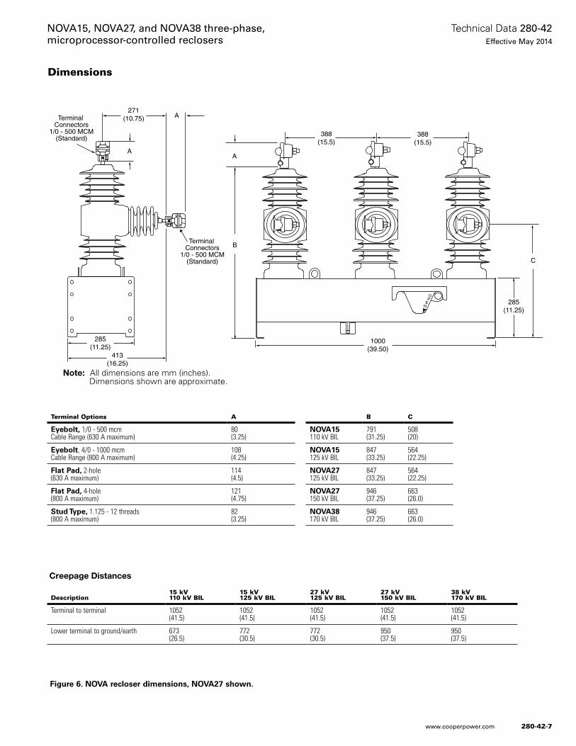
Figure 6. NOVA recloser dimensions, NOVA27 shown.
285(11.25)
Terminal Connectors
1/0 - 500 MCM(Standard)
Terminal Connectors
1/0 - 500 MCM(Standard)
NOTE: All dimensions are mm (inches). Dimensions shown are approximate.
A
271(10.75)
1000(39.50)
285(11.25)
OP
EN
B
C
A
A
413(16.25)
CLOSED
388(15.5)
388(15.5)
Creepage Distances
Dimensions
Note: All dimensions are mm (inches). Dimensions shown are approximate.
Terminal Options A
Eyebolt, 1/0 - 500 mcm Cable Range (630 A maximum)
80 (3.25)
Eyebolt, 4/0 - 1000 mcm Cable Range (800 A maximum)
108 (4.25)
Flat Pad, 2-hole (630 A maximum)
114 (4.5)
Flat Pad, 4-hole (800 A maximum)
121 (4.75)
Stud Type, 1.125 - 12 threads (800 A maximum)
82 (3.25)
B C
NOVA15 110 kV BIL
791 (31.25)
508 (20)
NOVA15 125 kV BIL
847 (33.25)
564 (22.25)
NOVA27 125 kV BIL
847 (33.25)
564 (22.25)
NOVA27 150 kV BIL
946 (37.25)
663 (26.0)
NOVA38 170 kV BIL
946 (37.25)
663 (26.0)
Description15 kV 110 kV BIL
15 kV 125 kV BIL
27 kV 125 kV BIL
27 kV 150 kV BIL
38 kV 170 kV BIL
Terminal to terminal 1052 (41.5)
1052 (41.5)
1052 (41.5)
1052 (41.5)
1052 (41.5)
Lower terminal to ground/earth 673 (26.5)
772 (30.5)
772 (30.5)
950 (37.5)
950 (37.5)
280-42-7
Technical Data 280-42Effective May 2014
NOVA15, NOVA27, and NOVA38 three-phase, microprocessor-controlled reclosers
www.cooperpower.com
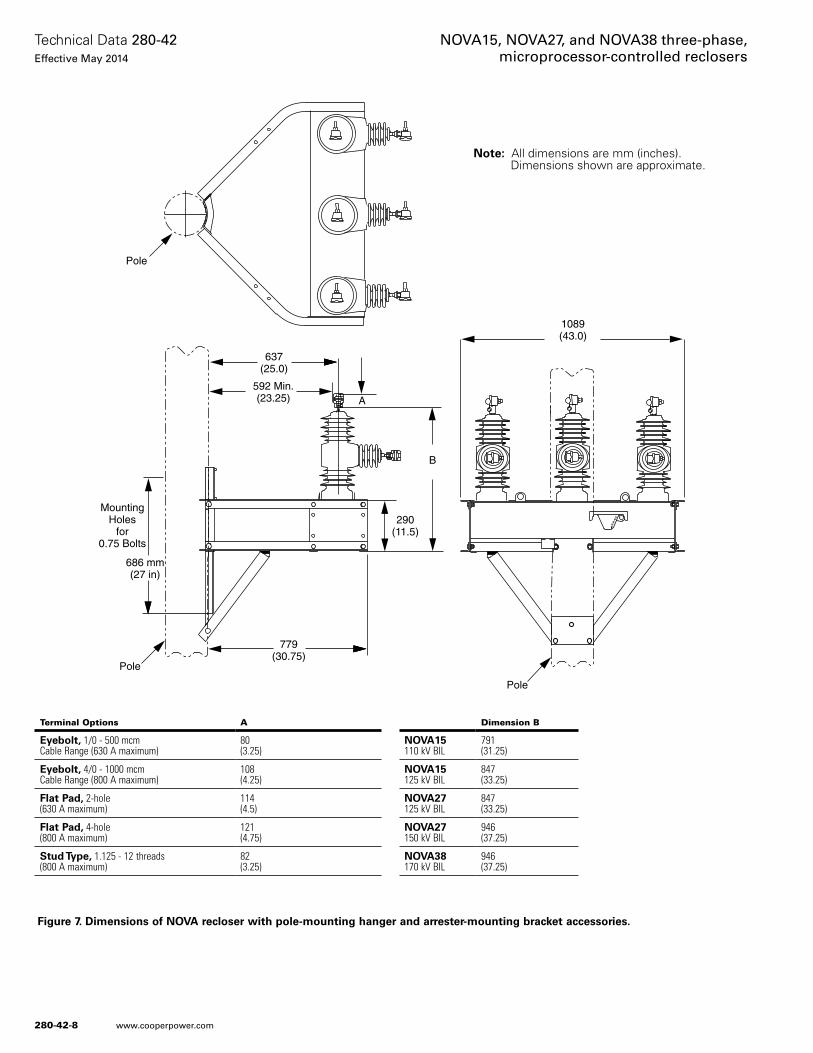
779(30.75)
Pole
686 mm(27 in)
Pole
637(25.0)
592 Min.(23.25)
MountingHoles
for0.75 Bolts
B
290(11.5)
A
1089(43.0)
OP
EN
Pole
Figure 7. Dimensions of NOVA recloser with pole-mounting hanger and arrester-mounting bracket accessories.
Note: All dimensions are mm (inches). Dimensions shown are approximate.
Terminal Options A
Eyebolt, 1/0 - 500 mcm Cable Range (630 A maximum)
80 (3.25)
Eyebolt, 4/0 - 1000 mcm Cable Range (800 A maximum)
108 (4.25)
Flat Pad, 2-hole (630 A maximum)
114 (4.5)
Flat Pad, 4-hole (800 A maximum)
121 (4.75)
Stud Type, 1.125 - 12 threads (800 A maximum)
82 (3.25)
Dimension B
NOVA15110 kV BIL
791 (31.25)
NOVA15125 kV BIL
847 (33.25)
NOVA27125 kV BIL
847 (33.25)
NOVA27150 kV BIL
946 (37.25)
NOVA38170 kV BIL
946 (37.25)
280-42-8
Technical Data 280-42Effective May 2014
NOVA15, NOVA27, and NOVA38 three-phase, microprocessor-controlled reclosers
www.cooperpower.com
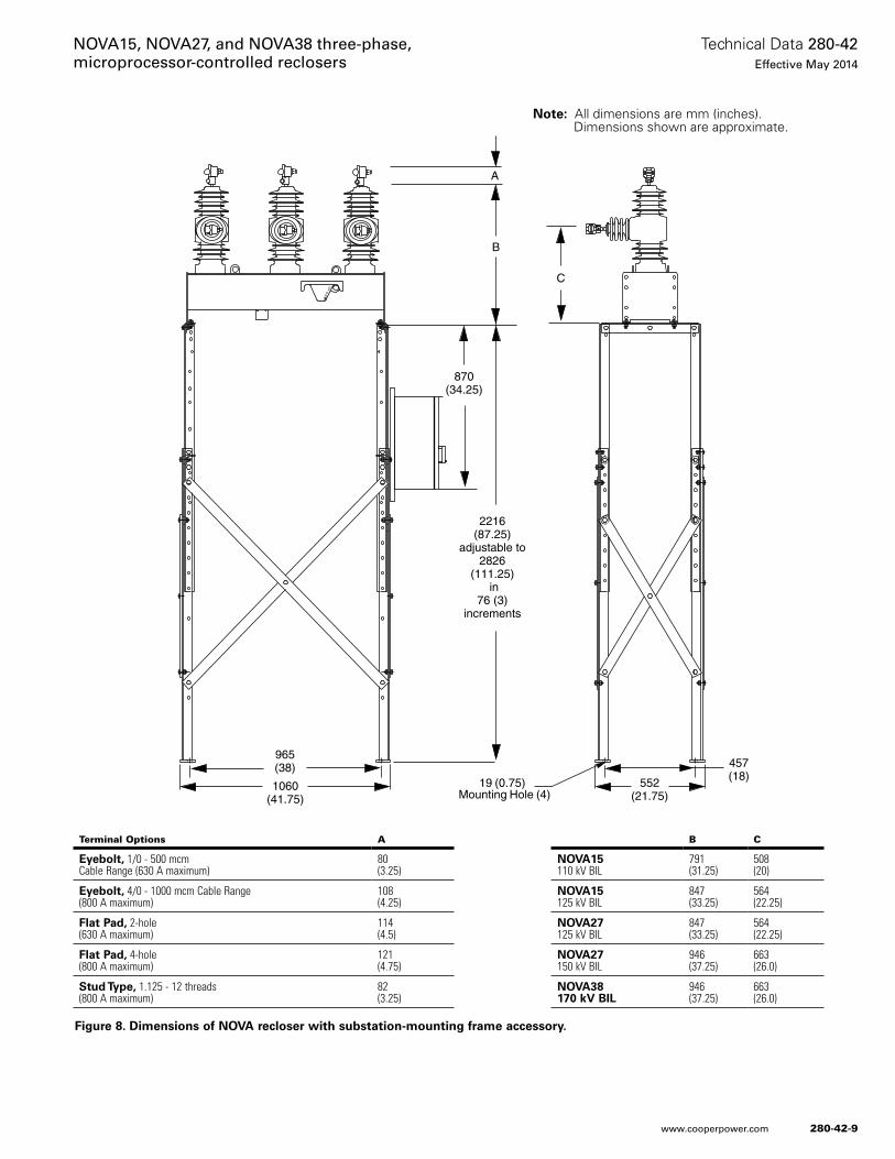
2216(87.25)
adjustable to2826
(111.25) in
76 (3)increments
1060(41.75)
965(38) 457
(18)552(21.75)
19 (0.75)Mounting Hole (4)
NOTE: All dimensions are mm (inches).
Dimensions shown are approximate.
B
OP
EN
C
870(34.25)
A
Figure 8. Dimensions of NOVA recloser with substation-mounting frame accessory.
Note: All dimensions are mm (inches). Dimensions shown are approximate.
Terminal Options A
Eyebolt, 1/0 - 500 mcm Cable Range (630 A maximum)
80 (3.25)
Eyebolt, 4/0 - 1000 mcm Cable Range (800 A maximum)
108 (4.25)
Flat Pad, 2-hole (630 A maximum)
114 (4.5)
Flat Pad, 4-hole (800 A maximum)
121 (4.75)
Stud Type, 1.125 - 12 threads (800 A maximum)
82 (3.25)
B C
NOVA15 110 kV BIL
791 (31.25)
508 (20)
NOVA15 125 kV BIL
847 (33.25)
564 (22.25)
NOVA27 125 kV BIL
847 (33.25)
564 (22.25)
NOVA27 150 kV BIL
946 (37.25)
663 (26.0)
NOVA38 170 kV BIL
946 (37.25)
663 (26.0)
280-42-9
Technical Data 280-42Effective May 2014
NOVA15, NOVA27, and NOVA38 three-phase, microprocessor-controlled reclosers
www.cooperpower.com
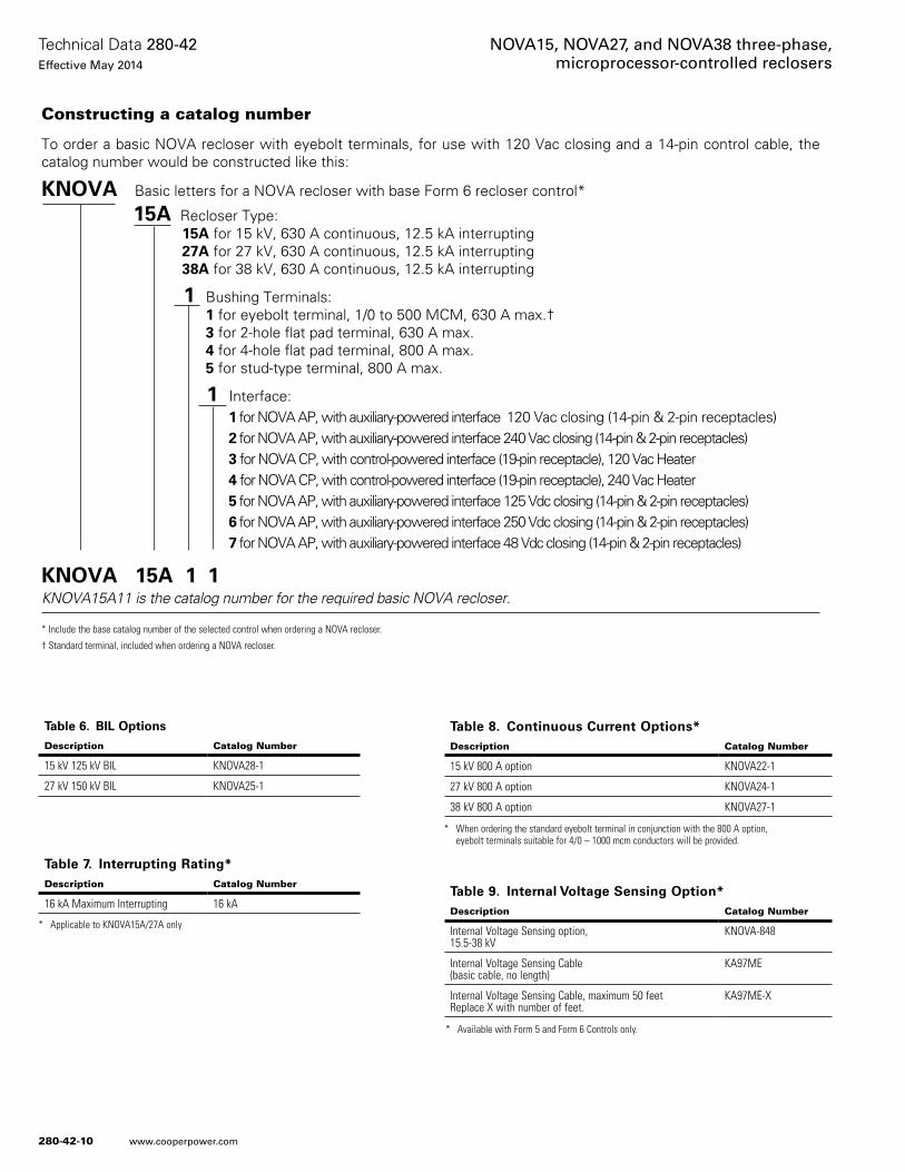
KNOVA Basic letters for a NOVA recloser with base Form 6 recloser control*
15A Recloser Type:15A for 15 kV, 630 A continuous, 12.5 kA interrupting 27A for 27 kV, 630 A continuous, 12.5 kA interrupting38A for 38 kV, 630 A continuous, 12.5 kA interrupting
1 Bushing Terminals: 1 for eyebolt terminal, 1/0 to 500 MCM, 630 A max.† 3 for 2-hole flat pad terminal, 630 A max. 4 for 4-hole flat pad terminal, 800 A max. 5 for stud-type terminal, 800 A max.
1 Interface:1 for NOVA AP, with auxiliary-powered interface 120 Vac closing (14-pin & 2-pin receptacles)2 for NOVA AP, with auxiliary-powered interface 240 Vac closing (14-pin & 2-pin receptacles)3 for NOVA CP, with control-powered interface (19-pin receptacle), 120 Vac Heater4 for NOVA CP, with control-powered interface (19-pin receptacle), 240 Vac Heater5 for NOVA AP, with auxiliary-powered interface 125 Vdc closing (14-pin & 2-pin receptacles)6 for NOVA AP, with auxiliary-powered interface 250 Vdc closing (14-pin & 2-pin receptacles)7 for NOVA AP, with auxiliary-powered interface 48 Vdc closing (14-pin & 2-pin receptacles)
KNOVA 15A 1 1KNOVA15A11 is the catalog number for the required basic NOVA recloser.
* Include the base catalog number of the selected control when ordering a NOVA recloser.
† Standard terminal, included when ordering a NOVA recloser.
Constructing a catalog number
To order a basic NOVA recloser with eyebolt terminals, for use with 120 Vac closing and a 14-pin control cable, the catalog number would be constructed like this:
* Available with Form 5 and Form 6 Controls only.
* Applicable to KNOVA15A/27A only
* When ordering the standard eyebolt terminal in conjunction with the 800 A option, eyebolt terminals suitable for 4/0 – 1000 mcm conductors will be provided.
Table 6. BIL Options
Description Catalog Number
15 kV 125 kV BIL KNOVA28-1
27 kV 150 kV BIL KNOVA25-1
Table 7. Interrupting Rating*Description Catalog Number
16 kA Maximum Interrupting 16 kA
Table 8. Continuous Current Options*Description Catalog Number
15 kV 800 A option KNOVA22-1
27 kV 800 A option KNOVA24-1
38 kV 800 A option KNOVA27-1
Table 9. Internal Voltage Sensing Option*Description Catalog Number
Internal Voltage Sensing option, 15.5-38 kV
KNOVA-848
Internal Voltage Sensing Cable (basic cable, no length)
KA97ME
Internal Voltage Sensing Cable, maximum 50 feet Replace X with number of feet.
KA97ME-X
280-42-10
Technical Data 280-42Effective May 2014
NOVA15, NOVA27, and NOVA38 three-phase, microprocessor-controlled reclosers
www.cooperpower.com
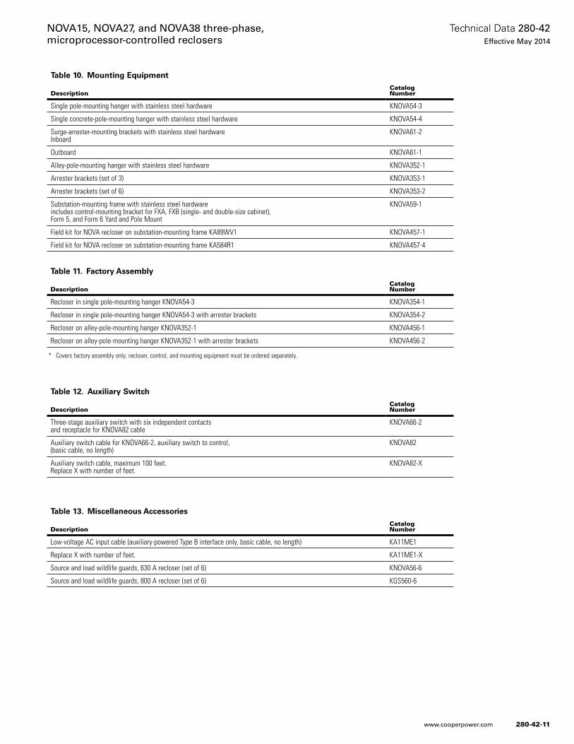
* Covers factory assembly only; recloser, control, and mounting equipment must be ordered separately.
Table 10. Mounting Equipment
DescriptionCatalogNumber
Single pole-mounting hanger with stainless steel hardware KNOVA54-3
Single concrete-pole-mounting hanger with stainless steel hardware KNOVA54-4
Surge-arrester-mounting brackets with stainless steel hardware Inboard
KNOVA61-2
Outboard KNOVA61-1
Alley-pole-mounting hanger with stainless steel hardware KNOVA352-1
Arrester brackets (set of 3) KNOVA353-1
Arrester brackets (set of 6) KNOVA353-2
Substation-mounting frame with stainless steel hardware includes control-mounting bracket for FXA, FXB (single- and double-size cabinet), Form 5, and Form 6 Yard and Pole Mount
KNOVA59-1
Field kit for NOVA recloser on substation-mounting frame KA89WV1 KNOVA457-1
Field kit for NOVA recloser on substation-mounting frame KA584R1 KNOVA457-4
Table 11. Factory Assembly
DescriptionCatalogNumber
Recloser in single pole-mounting hanger KNOVA54-3 KNOVA354-1
Recloser in single pole-mounting hanger KNOVA54-3 with arrester brackets KNOVA354-2
Recloser on alley-pole-mounting hanger KNOVA352-1 KNOVA456-1
Recloser on alley-pole-mounting hanger KNOVA352-1 with arrester brackets KNOVA456-2
Table 12. Auxiliary Switch
DescriptionCatalogNumber
Three-stage auxiliary switch with six independent contacts and receptacle for KNOVA82 cable
KNOVA66-2
Auxiliary switch cable for KNOVA66-2, auxiliary switch to control, (basic cable, no length)
KNOVA82
Auxiliary switch cable, maximum 100 feet. Replace X with number of feet.
KNOVA82-X
Table 13. Miscellaneous Accessories
DescriptionCatalogNumber
Low-voltage AC input cable (auxiliary-powered Type B interface only, basic cable, no length) KA11ME1
Replace X with number of feet. KA11ME1-X
Source and load wildlife guards, 630 A recloser (set of 6) KNOVA56-6
Source and load wildlife guards, 800 A recloser (set of 6) KGS560-6
280-42-11
Technical Data 280-42Effective May 2014
NOVA15, NOVA27, and NOVA38 three-phase, microprocessor-controlled reclosers
www.cooperpower.com
Eaton, Cooper Power Systems, and NOVA are valuable trademarks of Eaton in the U.S. and other countries. You are not permitted to use the these trademarks without the prior written consent of Eaton.IEEE Std C37.60™-2003 standard is a trademark of the Institute of Electrical and Electronics Engineers, Inc., (IEEE). This publication is not endorsed or approved by the IEEE.
NOVA15, NOVA27, and NOVA38 three-phase, microprocessor-controlled reclosers
Eaton1000 Eaton BoulevardCleveland, OH 44122United StatesEaton.com
Eaton’s Cooper Power Systems Business2300 Badger DriveWaukesha, WI 53188United StatesCooperpower.com
© 2014 EatonAll Rights ReservedPrinted in USAPublication No. 280-42May 2014
Technical Data 280-42Effective May 2014
For Eaton’s Cooper Power Systems NOVA recloser product information call 1-877-277-4636 or visit: www.cooperpower.com.
280-42-12
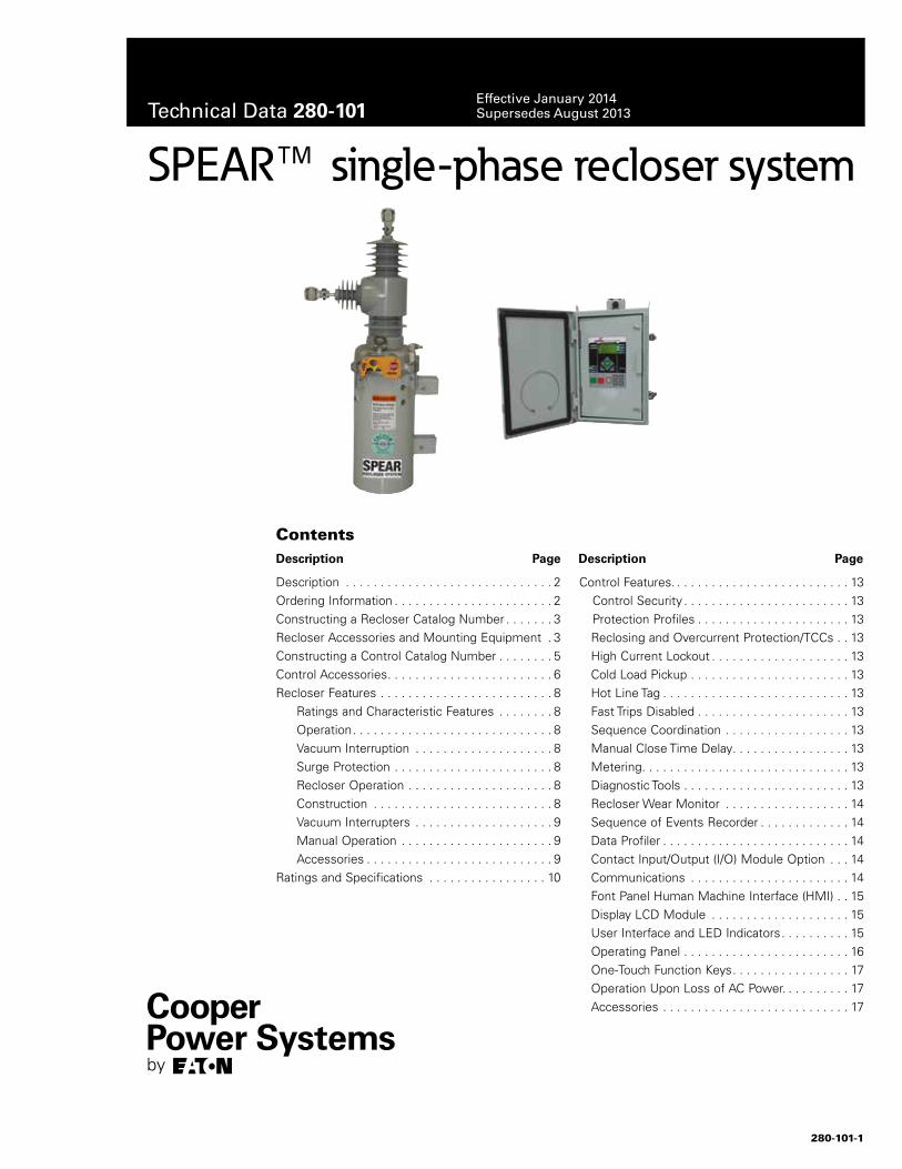
280-101-1
Description . . . . . . . . . . . . . . . . . . . . . . . . . . . . . . 2Ordering Information . . . . . . . . . . . . . . . . . . . . . . . 2Constructing a Recloser Catalog Number . . . . . . . 3Recloser Accessories and Mounting Equipment . 3Constructing a Control Catalog Number . . . . . . . . 5Control Accessories . . . . . . . . . . . . . . . . . . . . . . . . 6Recloser Features . . . . . . . . . . . . . . . . . . . . . . . . . 8 Ratings and Characteristic Features . . . . . . . . 8 Operation . . . . . . . . . . . . . . . . . . . . . . . . . . . . . 8 Vacuum Interruption . . . . . . . . . . . . . . . . . . . . 8 Surge Protection . . . . . . . . . . . . . . . . . . . . . . . 8 Recloser Operation . . . . . . . . . . . . . . . . . . . . . 8 Construction . . . . . . . . . . . . . . . . . . . . . . . . . . 8 Vacuum Interrupters . . . . . . . . . . . . . . . . . . . . 9 Manual Operation . . . . . . . . . . . . . . . . . . . . . . 9 Accessories . . . . . . . . . . . . . . . . . . . . . . . . . . . 9Ratings and Specifications . . . . . . . . . . . . . . . . . 10
Control Features . . . . . . . . . . . . . . . . . . . . . . . . . . 13 Control Security . . . . . . . . . . . . . . . . . . . . . . . . 13 Protection Profiles . . . . . . . . . . . . . . . . . . . . . . 13
Reclosing and Overcurrent Protection/TCCs . . 13High Current Lockout . . . . . . . . . . . . . . . . . . . . 13Cold Load Pickup . . . . . . . . . . . . . . . . . . . . . . . 13Hot Line Tag . . . . . . . . . . . . . . . . . . . . . . . . . . . 13Fast Trips Disabled . . . . . . . . . . . . . . . . . . . . . . 13Sequence Coordination . . . . . . . . . . . . . . . . . . 13Manual Close Time Delay . . . . . . . . . . . . . . . . . 13Metering . . . . . . . . . . . . . . . . . . . . . . . . . . . . . . 13Diagnostic Tools . . . . . . . . . . . . . . . . . . . . . . . . 13Recloser Wear Monitor . . . . . . . . . . . . . . . . . . 14Sequence of Events Recorder . . . . . . . . . . . . . 14Data Profiler . . . . . . . . . . . . . . . . . . . . . . . . . . . 14Contact Input/Output (I/O) Module Option . . . 14Communications . . . . . . . . . . . . . . . . . . . . . . . 14Font Panel Human Machine Interface (HMI) . . 15Display LCD Module . . . . . . . . . . . . . . . . . . . . 15User Interface and LED Indicators . . . . . . . . . . 15Operating Panel . . . . . . . . . . . . . . . . . . . . . . . . 16One-Touch Function Keys . . . . . . . . . . . . . . . . . 17Operation Upon Loss of AC Power . . . . . . . . . . 17Accessories . . . . . . . . . . . . . . . . . . . . . . . . . . . 17
SPEAR™ single-phase recloser system
ContentsDescription Page Description Page
Technical Data 280-101Effective January 2014 Supersedes August 2013
280-101-2
Technical Data 280-101Effective January 2014
SPEAR single-phase recloser system
www.cooperpower.com
DescriptionThe SPEAR™ single-phase recloser and control is the latest addition to Eaton’s Cooper Power Systems product offering for single-phase electronically controlled reclosers . This solution provides reliable, economical overcurrent protection, advanced metering, and SCADA communications for distribution circuits rated through 34 .5 kV .
Specifically with the SPEAR recloser, it uses a solid cycloaliphatic-epoxy polymer with an encapsulated vacuum interrupter . The SPEAR recloser’s mechanism is reliable, lightweight, and utilizes a magnetic actuator to provide a lifetime of trouble free operation . The solid polymer system does not rely on a gaseous, liquid, or foam dielectric insulating material . The SPEAR recloser is highly resistant to ozone, oxygen, moisture, contamination, and ultraviolet light .
Designed and tested with the SPEAR control, the SPEAR recloser offers superior coordination, protection, and application capabilities . Recloser operations are programmed using the SPEAR control with accurate characteristics and a host of advanced features . Precise operating tolerances enable close coordination with other protective devices on the system . When system requirements change, program settings are easily altered with no sacrifice of accuracy or consistency .
Compact and lightweight, SPEAR reclosers are easily installed on poles or in substations . Mounting equipment is available for both pole and substation mounting applications .
Recloser and control accessories enable further tailoring of the protective program to achieve maximum system operating flexibility .
The SPEAR control is the next in a line of fully integrated controls developed by Eaton’s Cooper Power Systems . This means one standard operating system and front panel to train technicians on . This translates to fewer training expenses, reduced inventory, and a distribution system that is much easier to maintain .
In addition to the flexible and user-friendly platform, the new SPEAR control has the communications technology to take your system into the future . With fully modular communication compatibilities, the SPEAR control supports cellular and radio communications utilizing Serial DNP3 protocol . A side panel RS-232 communications port is available for connection to SCADA or other devices . The communi-cation port is accessed by swing the control panel forward .
The SPEAR control can compute power, energy, power factor, and power flow direction based upon the recloser’s CT current output, and the customer supplied voltage input .
The standardized front panel of the SPEAR control can be used to program and interrogate the control, as well as to display metering and alarm information . Control parameters can also be programmed via personal computer using ProView™ NXG interface software . Temporary connection to the control can be made through the front panel USB port allowing programming and data downloads to a laptop or PC . The ProView NXG interface software includes the functionality modify time-current curves (TCCs), and provide diagnostic information . The SPEAR control analysis tools include event recording, data profiling, and various metering capabilities .
Ordering informationTo order a basic SPEAR recloser:
• See the Constructing a recloser catalog number section to construct a catalog number that describes the required recloser .
• From Tables 1 through 5, specify the catalog numbers that describe the required accessories .
To order a basic SPEAR control:
• On page 5, see the Constructing a control catalog number section that describes the required control .
• From Table 6, specify the catalog number that describes the required control cable .
• From Tables 7 through 12, specify the catalog numbers that describe the required accessories .
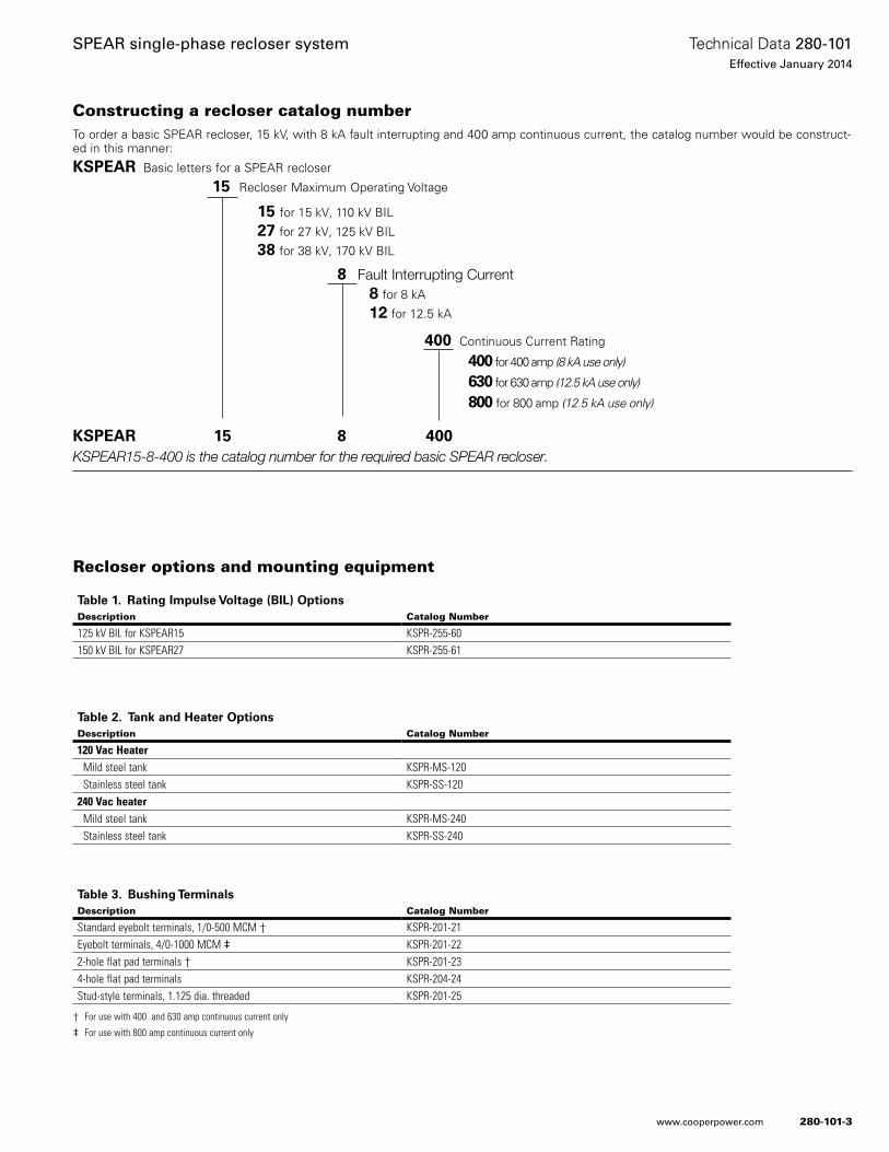
280-101-3
Technical Data 280-101Effective January 2014
SPEAR single-phase recloser system
www.cooperpower.com
Constructing a recloser catalog numberTo order a basic SPEAR recloser, 15 kV, with 8 kA fault interrupting and 400 amp continuous current, the catalog number would be construct-ed in this manner:
KSPEAR Basic letters for a SPEAR recloser
15 Recloser Maximum Operating Voltage
15 for 15 kV, 110 kV BIL
27 for 27 kV, 125 kV BIL
38 for 38 kV, 170 kV BIL
8 Fault Interrupting Current 8 for 8 kA
12 for 12 .5 kA
400 Continuous Current Rating
400 for 400 amp (8 kA use only)
630 for 630 amp (12.5 kA use only)
800 for 800 amp (12.5 kA use only)
KSPEAR 15 8 400KSPEAR15-8-400 is the catalog number for the required basic SPEAR recloser.
Recloser options and mounting equipment
Table 1. Rating Impulse Voltage (BIL) OptionsDescription Catalog Number
125 kV BIL for KSPEAR15 KSPR-255-60150 kV BIL for KSPEAR27 KSPR-255-61
Table 2. Tank and Heater OptionsDescription Catalog Number
120 Vac Heater Mild steel tank KSPR-MS-120 Stainless steel tank KSPR-SS-120240 Vac heater Mild steel tank KSPR-MS-240 Stainless steel tank KSPR-SS-240
Table 3. Bushing TerminalsDescription Catalog Number
Standard eyebolt terminals, 1/0-500 MCM † KSPR-201-21Eyebolt terminals, 4/0-1000 MCM ‡ KSPR-201-222-hole flat pad terminals † KSPR-201-234-hole flat pad terminals KSPR-204-24Stud-style terminals, 1.125 dia. threaded KSPR-201-25
† For use with 400 and 630 amp continuous current only
‡ For use with 800 amp continuous current only
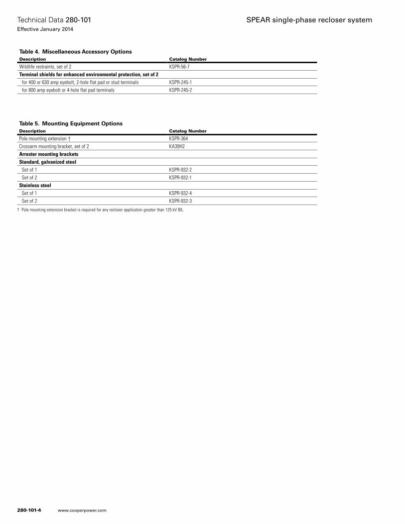
280-101-4
Technical Data 280-101Effective January 2014
SPEAR single-phase recloser system
www.cooperpower.com
Table 5. Mounting Equipment OptionsDescription Catalog Number
Pole mounting extension † KSPR-364Crossarm mounting bracket, set of 2 KA39H2Arrester mounting bracketsStandard, galvanized steel Set of 1 KSPR-932-2 Set of 2 KSPR-932-1Stainless steel Set of 1 KSPR-932-4 Set of 2 KSPR-932-3
Table 4. Miscellaneous Accessory OptionsDescription Catalog Number
Wildlife restraints, set of 2 KSPR-56-7Terminal shields for enhanced environmental protection, set of 2 for 400 or 630 amp eyebolt, 2-hole flat pad or stud terminals KSPR-245-1 for 800 amp eyebolt or 4-hole flat pad terminals KSPR-245-2
† Pole mounting extension bracket is required for any recloser application greater than 125 kV BIL.
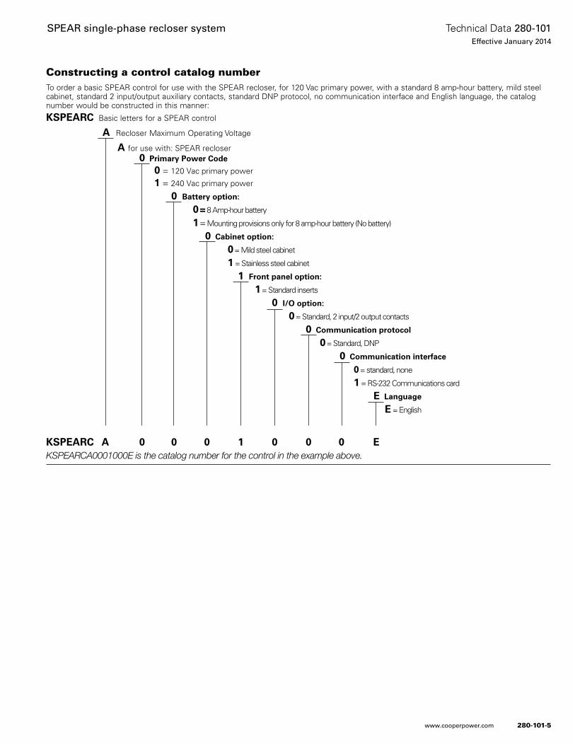
280-101-5
Technical Data 280-101Effective January 2014
SPEAR single-phase recloser system
www.cooperpower.com
Constructing a control catalog numberTo order a basic SPEAR control for use with the SPEAR recloser, for 120 Vac primary power, with a standard 8 amp-hour battery, mild steel cabinet, standard 2 input/output auxiliary contacts, standard DNP protocol, no communication interface and English language, the catalog number would be constructed in this manner:
KSPEARC Basic letters for a SPEAR control
A Recloser Maximum Operating Voltage
A for use with: SPEAR recloser0 Primary Power Code
0 = 120 Vac primary power
1 = 240 Vac primary power
0 Battery option:
0 = 8 Amp-hour battery
1 = Mounting provisions only for 8 amp-hour battery (No battery)
0 Cabinet option:
0 = Mild steel cabinet
1 = Stainless steel cabinet
1 Front panel option:
1 = Standard inserts
0 I/O option:
0 = Standard, 2 input/2 output contacts
0 Communication protocol
0 = Standard, DNP
0 Communication interface
0 = standard, none
1 = RS-232 Communications card
E Language
E = English
KSPEARC A 0 0 0 1 0 0 0 EKSPEARCA0001000E is the catalog number for the control in the example above.

280-101-6
Technical Data 280-101Effective January 2014
SPEAR single-phase recloser system
www.cooperpower.com
Table 6. Control CablesDescription Catalog Number
Control cable: (basic cable, no length) KA148ME Replace “X” with desired length. Select from 5 to 50 feet. KA148ME-XArmored (10 ft.) control cable: (basic cable, no length) KA149ME Replace “X” with desired length. Select from 11 to 50 feet. KA149ME-X
Control accessories
Table 7. Receptacles and WiringDescription Catalog Number
AC input receptacles 120 Vac or 240 Vac input receptacle, 2-pin KSPRC-1775-H 120 Vac input receptacle, 3-pin KSPRC-1775-J No input receptacle; for hard-wiring input KSPRC-1775-0
Table 8. Input CablesDescription Catalog Number
AC input cables Input cable, 120 or 240 Vac, two-wire for 2-pin input, for use with KSPRC-1775-H receptacle. (Basic cable, no length)
KA11ME1
Replace “X” with desired length. Select from 0-50 feet.* KA11ME1-XArmored (10 ft) input cable: (Basic cable, no length) KA124ME Replace “X” with desired length. Select from 10-50 feet. KA124ME-X Input cable, 120 Vac, three-wire for 3-pin input, for use with KSPRC-1775-J receptacle. (Basic cable, no length)
KME4-67-3
Replace “X” with desired length. Select from 0-50 feet.* KME4-67-3-X* To order a mating plug body only (no cable, for customer supplied cable), enter length as “0”.
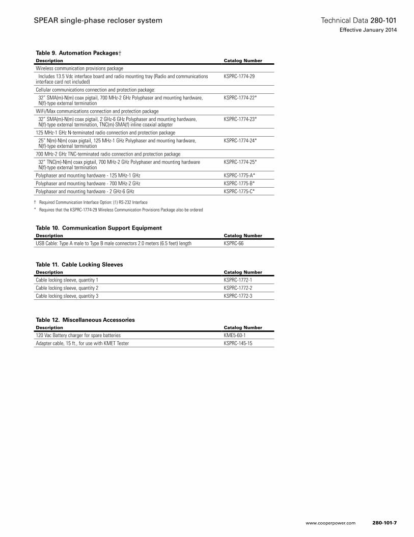
280-101-7
Technical Data 280-101Effective January 2014
SPEAR single-phase recloser system
www.cooperpower.com
Table 9. Automation Packages†Description Catalog Number
Wireless communication provisions package Includes 13.5 Vdc interface board and radio mounting tray (Radio and communications interface card not included)
KSPRC-1774-29
Cellular communications connection and protection package: 32” SMA(m)-N(m) coax pigtail, 700 MHz-2 GHz Polyphaser and mounting hardware, N(f)-type external termination
KSPRC-1774-22*
WiFi/Max communications connection and protection package 32” SMA(m)-N(m) coax pigtail, 2 GHz-6 GHz Polyphaser and mounting hardware, N(f)-type external termination, TNC(m)-SMA(f) inline coaxial adapter
KSPRC-1774-23*
125 MHz-1 GHz N-terminated radio connection and protection package 25” N(m)-N(m) coax pigtail, 125 MHz-1 GHz Polyphaser and mounting hardware, N(f)-type external termination
KSPRC-1774-24*
700 MHz-2 GHz TNC-terminated radio connection and protection package 32” TNC(m)-N(m) coax pigtail, 700 MHz-2 GHz Polyphaser and mounting hardware N(f)-type external termination
KSPRC-1774-25*
Polyphaser and mounting hardware - 125 MHz-1 GHz KSPRC-1775-A*Polyphaser and mounting hardware - 700 MHz-2 GHz KSPRC-1775-B*Polyphaser and mounting hardware - 2 GHz-6 GHz KSPRC-1775-C*
† Required Communication Interface Option: (1) RS-232 Interface* Requires that the KSPRC-1774-29 Wireless Communication Provisions Package also be ordered
Table 10. Communication Support EquipmentDescription Catalog Number
USB Cable: Type A male to Type B male connectors 2.0 meters (6.5 feet) length KSPRC-66
Table 11. Cable Locking SleevesDescription Catalog Number
Cable locking sleeve, quantity 1 KSPRC-1772-1Cable locking sleeve, quantity 2 KSPRC-1772-2Cable locking sleeve, quantity 3 KSPRC-1772-3
Table 12. Miscellaneous AccessoriesDescription Catalog Number
120 Vac Battery charger for spare batteries KME5-60-1Adapter cable, 15 ft., for use with KMET Tester KSPRC-145-15
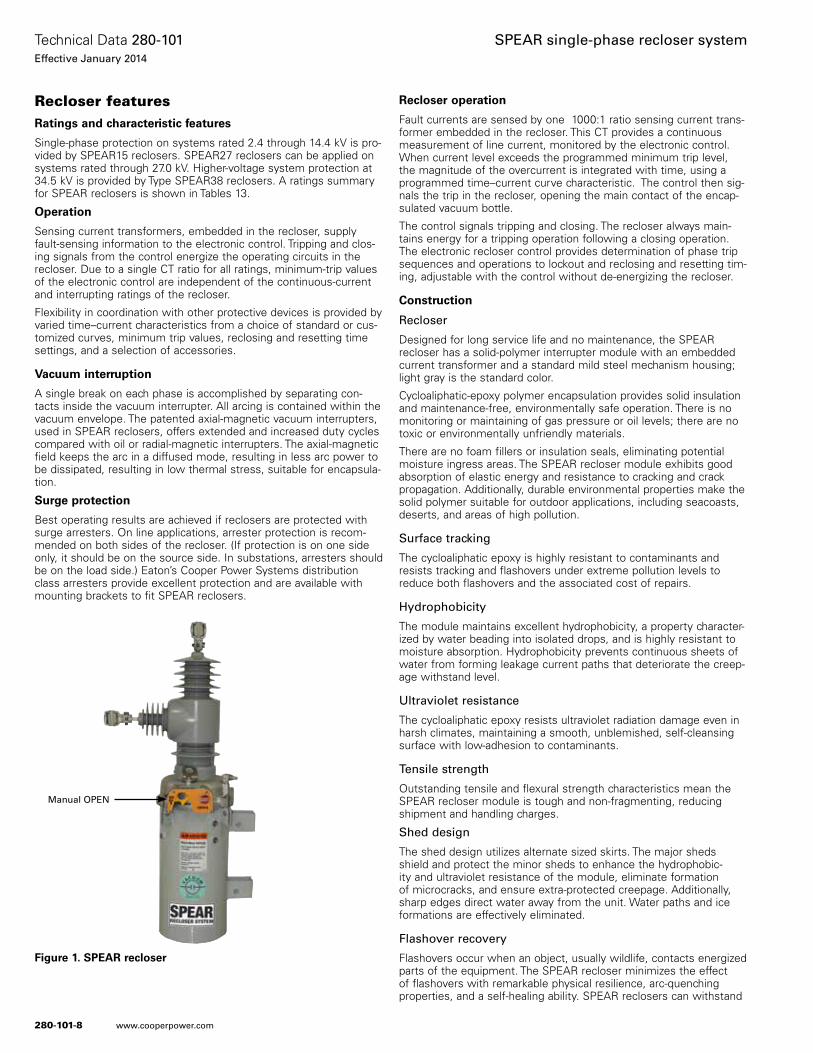
280-101-8
Technical Data 280-101Effective January 2014
SPEAR single-phase recloser system
www.cooperpower.com
Recloser featuresRatings and characteristic features
Single-phase protection on systems rated 2 .4 through 14 .4 kV is pro-vided by SPEAR15 reclosers . SPEAR27 reclosers can be applied on systems rated through 27 .0 kV . Higher-voltage system protection at 34 .5 kV is provided by Type SPEAR38 reclosers . A ratings summary for SPEAR reclosers is shown in Tables 13 .
Operation
Sensing current transformers, embedded in the recloser, supply fault-sensing information to the electronic control . Tripping and clos-ing signals from the control energize the operating circuits in the recloser . Due to a single CT ratio for all ratings, minimum-trip values of the electronic control are independent of the continuous-current and interrupting ratings of the recloser .
Flexibility in coordination with other protective devices is provided by varied time–current characteristics from a choice of standard or cus-tomized curves, minimum trip values, reclosing and resetting time settings, and a selection of accessories .
Vacuum interruption
A single break on each phase is accomplished by separating con-tacts inside the vacuum interrupter . All arcing is contained within the vacuum envelope . The patented axial-magnetic vacuum interrupters, used in SPEAR reclosers, offers extended and increased duty cycles compared with oil or radial-magnetic interrupters . The axial-magnetic field keeps the arc in a diffused mode, resulting in less arc power to be dissipated, resulting in low thermal stress, suitable for encapsula-tion .
Surge protection
Best operating results are achieved if reclosers are protected with surge arresters . On line applications, arrester protection is recom-mended on both sides of the recloser . (If protection is on one side only, it should be on the source side . In substations, arresters should be on the load side .) Eaton’s Cooper Power Systems distribution class arresters provide excellent protection and are available with mounting brackets to fit SPEAR reclosers .
Recloser operation
Fault currents are sensed by one 1000:1 ratio sensing current trans-former embedded in the recloser . This CT provides a continuous measurement of line current, monitored by the electronic control . When current level exceeds the programmed minimum trip level, the magnitude of the overcurrent is integrated with time, using a programmed time–current curve characteristic . The control then sig-nals the trip in the recloser, opening the main contact of the encap-sulated vacuum bottle .
The control signals tripping and closing . The recloser always main-tains energy for a tripping operation following a closing operation . The electronic recloser control provides determination of phase trip sequences and operations to lockout and reclosing and resetting tim-ing, adjustable with the control without de-energizing the recloser .
Construction
Recloser
Designed for long service life and no maintenance, the SPEAR recloser has a solid-polymer interrupter module with an embedded current transformer and a standard mild steel mechanism housing; light gray is the standard color .
Cycloaliphatic-epoxy polymer encapsulation provides solid insulation and maintenance-free, environmentally safe operation . There is no monitoring or maintaining of gas pressure or oil levels; there are no toxic or environmentally unfriendly materials .
There are no foam fillers or insulation seals, eliminating potential moisture ingress areas . The SPEAR recloser module exhibits good absorption of elastic energy and resistance to cracking and crack propagation . Additionally, durable environmental properties make the solid polymer suitable for outdoor applications, including seacoasts, deserts, and areas of high pollution .
Surface tracking
The cycloaliphatic epoxy is highly resistant to contaminants and resists tracking and flashovers under extreme pollution levels to reduce both flashovers and the associated cost of repairs .
Hydrophobicity
The module maintains excellent hydrophobicity, a property character-ized by water beading into isolated drops, and is highly resistant to moisture absorption . Hydrophobicity prevents continuous sheets of water from forming leakage current paths that deteriorate the creep-age withstand level .
Ultraviolet resistance
The cycloaliphatic epoxy resists ultraviolet radiation damage even in harsh climates, maintaining a smooth, unblemished, self-cleansing surface with low-adhesion to contaminants .
Tensile strength
Outstanding tensile and flexural strength characteristics mean the SPEAR recloser module is tough and non-fragmenting, reducing shipment and handling charges .
Shed design
The shed design utilizes alternate sized skirts . The major sheds shield and protect the minor sheds to enhance the hydrophobic-ity and ultraviolet resistance of the module, eliminate formation of microcracks, and ensure extra-protected creepage . Additionally, sharp edges direct water away from the unit . Water paths and ice formations are effectively eliminated .
Flashover recovery
Flashovers occur when an object, usually wildlife, contacts energized parts of the equipment . The SPEAR recloser minimizes the effect of flashovers with remarkable physical resilience, arc-quenching properties, and a self-healing ability . SPEAR reclosers can withstand
Manual OPEN
Figure 1. SPEAR recloser
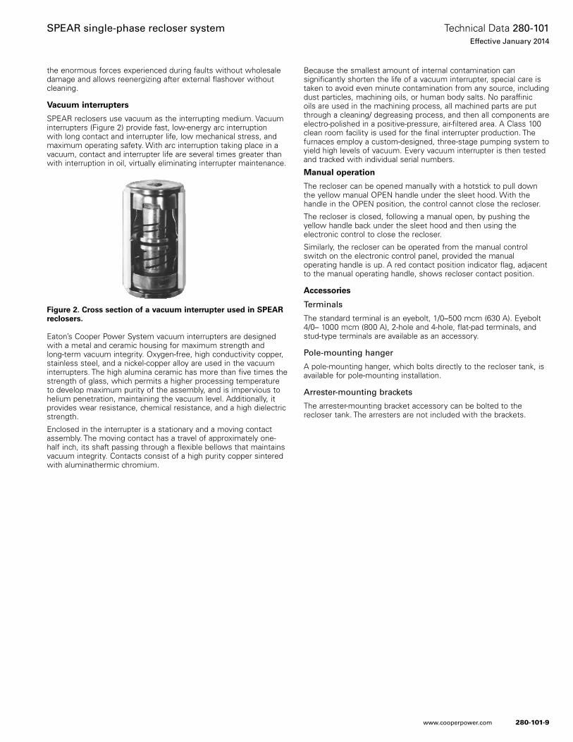
280-101-9
Technical Data 280-101Effective January 2014
SPEAR single-phase recloser system
www.cooperpower.com
the enormous forces experienced during faults without wholesale damage and allows reenergizing after external flashover without cleaning .
Vacuum interrupters
SPEAR reclosers use vacuum as the interrupting medium . Vacuum interrupters (Figure 2) provide fast, low-energy arc interruption with long contact and interrupter life, low mechanical stress, and maximum operating safety . With arc interruption taking place in a vacuum, contact and interrupter life are several times greater than with interruption in oil, virtually eliminating interrupter maintenance .
Eaton’s Cooper Power System vacuum interrupters are designed with a metal and ceramic housing for maximum strength and long-term vacuum integrity . Oxygen-free, high conductivity copper, stainless steel, and a nickel-copper alloy are used in the vacuum interrupters . The high alumina ceramic has more than five times the strength of glass, which permits a higher processing temperature to develop maximum purity of the assembly, and is impervious to helium penetration, maintaining the vacuum level . Additionally, it provides wear resistance, chemical resistance, and a high dielectric strength .
Enclosed in the interrupter is a stationary and a moving contact assembly . The moving contact has a travel of approximately one-half inch, its shaft passing through a flexible bellows that maintains vacuum integrity . Contacts consist of a high purity copper sintered with aluminathermic chromium .
Because the smallest amount of internal contamination can significantly shorten the life of a vacuum interrupter, special care is taken to avoid even minute contamination from any source, including dust particles, machining oils, or human body salts . No paraffinic oils are used in the machining process, all machined parts are put through a cleaning/ degreasing process, and then all components are electro-polished in a positive-pressure, air-filtered area . A Class 100 clean room facility is used for the final interrupter production . The furnaces employ a custom-designed, three-stage pumping system to yield high levels of vacuum . Every vacuum interrupter is then tested and tracked with individual serial numbers .
Manual operation
The recloser can be opened manually with a hotstick to pull down the yellow manual OPEN handle under the sleet hood . With the handle in the OPEN position, the control cannot close the recloser .
The recloser is closed, following a manual open, by pushing the yellow handle back under the sleet hood and then using the electronic control to close the recloser .
Similarly, the recloser can be operated from the manual control switch on the electronic control panel, provided the manual operating handle is up . A red contact position indicator flag, adjacent to the manual operating handle, shows recloser contact position .
Accessories
Terminals
The standard terminal is an eyebolt, 1/0–500 mcm (630 A) . Eyebolt 4/0– 1000 mcm (800 A), 2-hole and 4-hole, flat-pad terminals, and stud-type terminals are available as an accessory .
Pole-mounting hanger
A pole-mounting hanger, which bolts directly to the recloser tank, is available for pole-mounting installation .
Arrester-mounting brackets
The arrester-mounting bracket accessory can be bolted to the recloser tank . The arresters are not included with the brackets .
Figure 2. Cross section of a vacuum interrupter used in SPEAR reclosers.
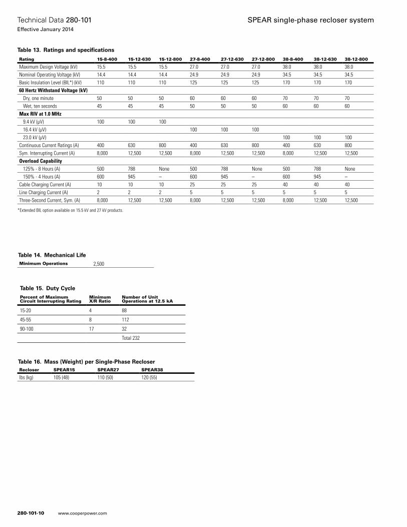
280-101-10
Technical Data 280-101Effective January 2014
SPEAR single-phase recloser system
www.cooperpower.com
Table 14. Mechanical LifeMinimum Operations 2,500
Table 16. Mass (Weight) per Single-Phase RecloserRecloser SPEAR15 SPEAR27 SPEAR38
lbs (kg) 105 (48) 110 (50) 120 (55)
Table 15. Duty Cycle
Percent of Maximum Circuit Interrupting Rating
Minimum X/R Ratio
Number of Unit Operations at 12.5 kA
15-20 4 88
45-55 8 112
90-100 17 32
Total 232
Rating 15-8-400 15-12-630 15-12-800 27-8-400 27-12-630 27-12-800 38-8-400 38-12-630 38-12-800
Maximum Design Voltage (kV) 15.5 15.5 15.5 27.0 27.0 27.0 38.0 38.0 38.0Nominal Operating Voltage (kV) 14.4 14.4 14.4 24.9 24.9 24.9 34.5 34.5 34.5Basic Insulation Level (BIL*) (kV) 110 110 110 125 125 125 170 170 17060 Hertz Withstand Voltage (kV) Dry, one minute 50 50 50 60 60 60 70 70 70 Wet, ten seconds 45 45 45 50 50 50 60 60 60Max RIV at 1.0 MHz 9.4 kV (µV) 100 100 100 16.4 kV (µV) 100 100 100 23.0 kV (µV) 100 100 100Continuous Current Ratings (A) 400 630 800 400 630 800 400 630 800Sym. Interrupting Current (A) 8,000 12,500 12,500 8,000 12,500 12,500 8,000 12,500 12,500Overload Capability 125% - 8 Hours (A) 500 788 None 500 788 None 500 788 None 150% - 4 Hours (A) 600 945 – 600 945 – 600 945 –
Cable Charging Current (A) 10 10 10 25 25 25 40 40 40Line Charging Current (A) 2 2 2 5 5 5 5 5 5Three-Second Current, Sym. (A) 8,000 12,500 12,500 8,000 12,500 12,500 8,000 12,500 12,500
*Extended BIL option available on 15.5 kV and 27 kV products.
Table 13. Ratings and specifications
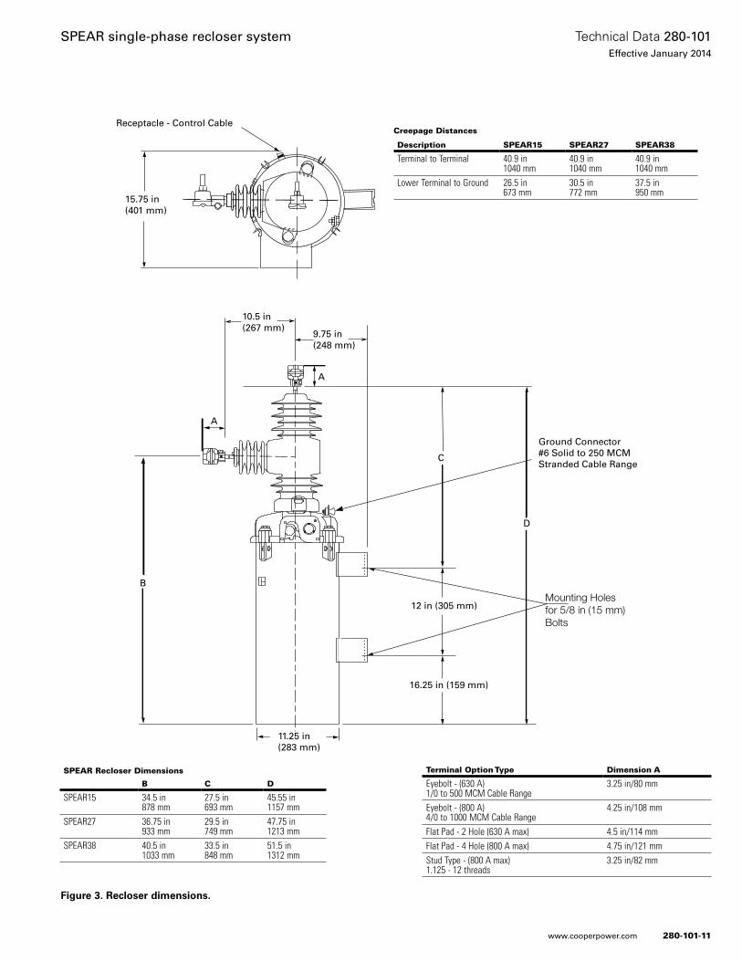
280-101-11
Technical Data 280-101Effective January 2014
SPEAR single-phase recloser system
www.cooperpower.com
15.75 in(401 mm)
Receptacle - Control Cable
10.5 in(267 mm)
9.75 in(248 mm)
11.25 in(283 mm)
16.25 in (159 mm)
12 in (305 mm)
Ground Connector#6 Solid to 250 MCMStranded Cable Range
Mounting Holesfor 5/8 in (15 mm)Bolts
A
A
B
C
D
SPEAR Recloser Dimensions
B C D
SPEAR15 34.5 in878 mm
27.5 in693 mm
45.55 in1157 mm
SPEAR27 36.75 in933 mm
29.5 in749 mm
47.75 in1213 mm
SPEAR38 40.5 in1033 mm
33.5 in848 mm
51.5 in1312 mm
Creepage Distances
Description SPEAR15 SPEAR27 SPEAR38
Terminal to Terminal 40.9 in1040 mm
40.9 in1040 mm
40.9 in1040 mm
Lower Terminal to Ground 26.5 in 673 mm
30.5 in772 mm
37.5 in950 mm
Terminal Option Type Dimension A
Eyebolt - (630 A)1/0 to 500 MCM Cable Range
3.25 in/80 mm
Eyebolt - (800 A)4/0 to 1000 MCM Cable Range
4.25 in/108 mm
Flat Pad - 2 Hole (630 A max) 4.5 in/114 mmFlat Pad - 4 Hole (800 A max) 4.75 in/121 mmStud Type - (800 A max)1.125 - 12 threads
3.25 in/82 mm
Figure 3. Recloser dimensions.
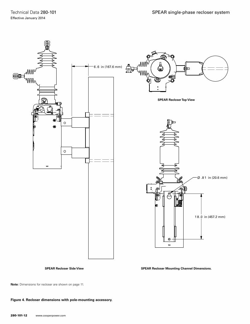
280-101-12
Technical Data 280-101Effective January 2014
SPEAR single-phase recloser system
www.cooperpower.com
SPEAR Recloser Side View
SPEAR Recloser Top View
6 .6 in (167.6 mm)
1 8 .0 in (457.2 mm)
.8 1 in (20.6 mm)Ø
6 .6 in (167.6 mm)
1 8 .0 in (457.2 mm)
.8 1 in (20.6 mm)Ø
6 .6 in (167.6 mm)
1 8 .0 in (457.2 mm)
.8 1 in (20.6 mm)Ø
SPEAR Recloser Mounting Channel Dimensions.
Figure 4. Recloser dimensions with pole-mounting accessory.
ote:N Dimensions for recloser are shown on page 11 .

280-101-13
Technical Data 280-101Effective January 2014
SPEAR single-phase recloser system
www.cooperpower.com
Control featuresControl security
The SPEAR single-phase recloser control has multiple customer-programmable security codes to limit control programming and viewing function access to authorized personnel . The SPEAR control is capable of supporting numeric passwords . The front panel Human-Machine Interface (HMI) includes a user-selected security code to access the settings . Plus, the ProView NXG interface software has its own security levels for multiple-user access .
Protection profiles
The SPEAR control provides two protection profiles, each capable of fully specifying the operation of the control . The protection profiles are selectable through the front-panel push button interface or through the interface software and USB communication port . Each protection profile contains overcurrent protection and operation settings .
Reclosing and overcurrent protection/TCCs
The SPEAR control offers flexible phase overcurrent protection which can be programmed with up to four operations-to-lockout . Each time-current curve (TCC) can be individually programmed from up to fifty-four standard curves which can be further customized . Time-current curves are available for fast and delayed operations . Reclose intervals and reset time can also be programmed by the user .
High current lockout
The High Current Lockout (HCL) feature will automatically lockout the control when the current exceeds a programmed threshold . The active number of selectable operations to lockout is independently selectable for each protection profile .
Cold load pickup
The SPEAR control provides a Cold Load Pickup (CLPU) feature that will prevent the control from tripping due to short-term increases in current caused by loss of normal load diversity or feeder inrush . This feature has an independently programmable minimum trip value, time-current curve, reclose interval, and number of operations to lockout for each protection profile . The CLPU feature will also inhibit ‘normal’ overcurrent protection during the CLPU active time .
Hot line tag
The SPEAR control includes a Hot Line Tag (HLT) membrane push button that will block all Close operations, local or remote, for live-line work . The control will trip on one operation-to-lockout on the composite curve of the HLT definite time and the TCC1 curve, whichever is faster, when HLT is active . Hot Line Tag takes pre-cedence over Cold Load Pickup, Non-Reclosing, and Fast Trips Disabled . The Hot Line Tag time delay is independently selectable for each protection profile .
Fast trips disabled
The Fast Trips Disabled feature will ignore the normal TCCs and num-ber of trips and instead use the Fast Trips Disabled settings when Fast Trips Disabled is active . Fast Trips Disabled is independently selectable for each protection profile .
Sequence coordination
The SPEAR control Sequence Coordination feature will allow the control to step through selected operations in the operating sequence without tripping when a down-line recloser is proceeding through its reclose sequence . The number of advances is program-mable from one to three operations to provide trip coordination with the down-line recloser .
Manual close time delay
The SPEAR control includes a Manual Close Delay which provides a delay from the time the manual CLOSE button is pushed to the time the manual close operation is performed .
Metering
The SPEAR control comes equipped with a full complement of metering capabilities, which include instantaneous, demand, demand peak, and energy metering . The control will be capable of the follow-ing metering values:• Real and reactive power, including direction of power flow• Demand currents• Instantaneous currents• Instantaneous voltage• Instantaneous frequency• Energy• Instantaneous power factor• Metering Settings which include demand interval, and alarm
thresholds for current, voltage, frequency, power factor, frequen-cy, kVA, kVAR, and kW
Diagnostic tools
The SPEAR control comes complete with a suite of diagnostic tools to help troubleshoot problems, analyze system events and condi-tions, and monitor the life of your recloser . All diagnostic information is stored in non-volatile memory so even if the control loses power, all system and event information will remain intact .
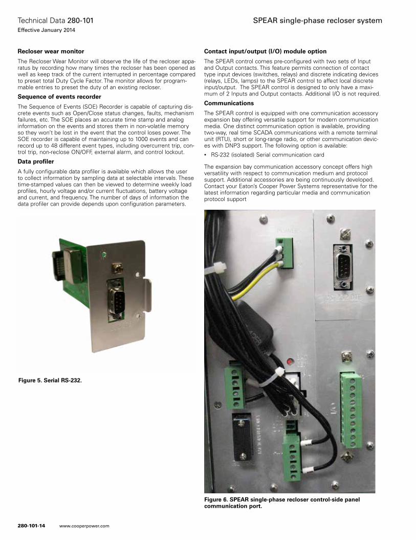
280-101-14
Technical Data 280-101Effective January 2014
SPEAR single-phase recloser system
www.cooperpower.com
Recloser wear monitor
The Recloser Wear Monitor will observe the life of the recloser appa-ratus by recording how many times the recloser has been opened as well as keep track of the current interrupted in percentage compared to preset total Duty Cycle Factor . The monitor allows for program-mable entries to preset the duty of an existing recloser .
Sequence of events recorder
The Sequence of Events (SOE) Recorder is capable of capturing dis-crete events such as Open/Close status changes, faults, mechanism failures, etc . The SOE places an accurate time stamp and analog information on the events and stores them in non-volatile memory so they won’t be lost in the event that the control loses power . The SOE recorder is capable of maintaining up to 1000 events and can record up to 48 different event types, including overcurrent trip, con-trol trip, non-reclose ON/OFF, external alarm, and control lockout .
Data profiler
A fully configurable data profiler is available which allows the user to collect information by sampling data at selectable intervals . These time-stamped values can then be viewed to determine weekly load profiles, hourly voltage and/or current fluctuations, battery voltage and current, and frequency . The number of days of information the data profiler can provide depends upon configuration parameters .
Contact input/output (I/O) module option
The SPEAR control comes pre-configured with two sets of Input and Output contacts . This feature permits connection of contact type input devices (switches, relays) and discrete indicating devices (relays, LEDs, lamps) to the SPEAR control to affect local discrete input/output . The SPEAR control is designed to only have a maxi-mum of 2 Inputs and Output contacts . Additional I/O is not required .
Communications
The SPEAR control is equipped with one communication accessory expansion bay offering versatile support for modern communication media . One distinct communication option is available, providing two-way, real time SCADA communications with a remote terminal unit (RTU), short or long-range radio, or other communication devic-es with DNP3 support . The following option is available:• RS-232 (isolated) Serial communication card
The expansion bay communication accessory concept offers high versatility with respect to communication medium and protocol support . Additional accessories are being continuously developed . Contact your Eaton’s Cooper Power Systems representative for the latest information regarding particular media and communication protocol support
Figure 6. SPEAR single-phase recloser control-side panel communication port.
Figure 5. Serial RS-232.
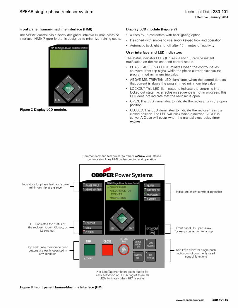
280-101-15
Technical Data 280-101Effective January 2014
SPEAR single-phase recloser system
www.cooperpower.com
Front panel human-machine interface (HMI)
The SPEAR control has a newly designed, intuitive Human-Machine Interface (HMI) (Figure 8) that is designed to minimize training costs .
Display LCD module (Figure 7)
• 4 lines-by-16 characters with backlighting option• Designed with simple to use arrow keypad look and operation• Automatic backlight shut off after 15 minutes of inactivity
User interface and LED indicators
The status indicator LEDs (Figures 9 and 10) provide instant notification on the recloser and control status .• PHASE FAULT: This LED illuminates when the control issues
an overcurrent trip signal while the phase current exceeds the programmed minimum trip value .
• ABOVE MIN TRIP: This LED illuminates when the control detects that current is above the programmed minimum trip value
• LOCKOUT: This LED illuminates to indicate the control is in a locked out state, i .e . a reclosing sequence is not in progress . This LED does not indicate that the recloser is open .
• OPEN: This LED illuminates to indicate the recloser is in the open position
• CLOSED: This LED illuminates to indicate the recloser is in the closed position . The LED will blink when a delayed CLOSE is active . A Close will occur when the manual close delay timer expires .
Indicators for phase fault and above minimum trip at a glance
LED indicates the status of the recloser (Open, Closed, or
Locked out)
Trip and Close membrane push buttons are easily operated in
any condition
Hot Line Tag membrane push button for easy activation of HLT . A ring of three (3)
LEDs indicates when HLT is active .
Indicators show control diagnostics
Front panel USB port allow for easy connection to laptop
Soft-keys allow for single push activation of commonly used
control functions
Common look and feel similar to other ProView NXG Based controls simplifies HMI understanding and operation
Figure 8. Front panel Human-Machine Interface (HMI).
Figure 7. Display LCD module.
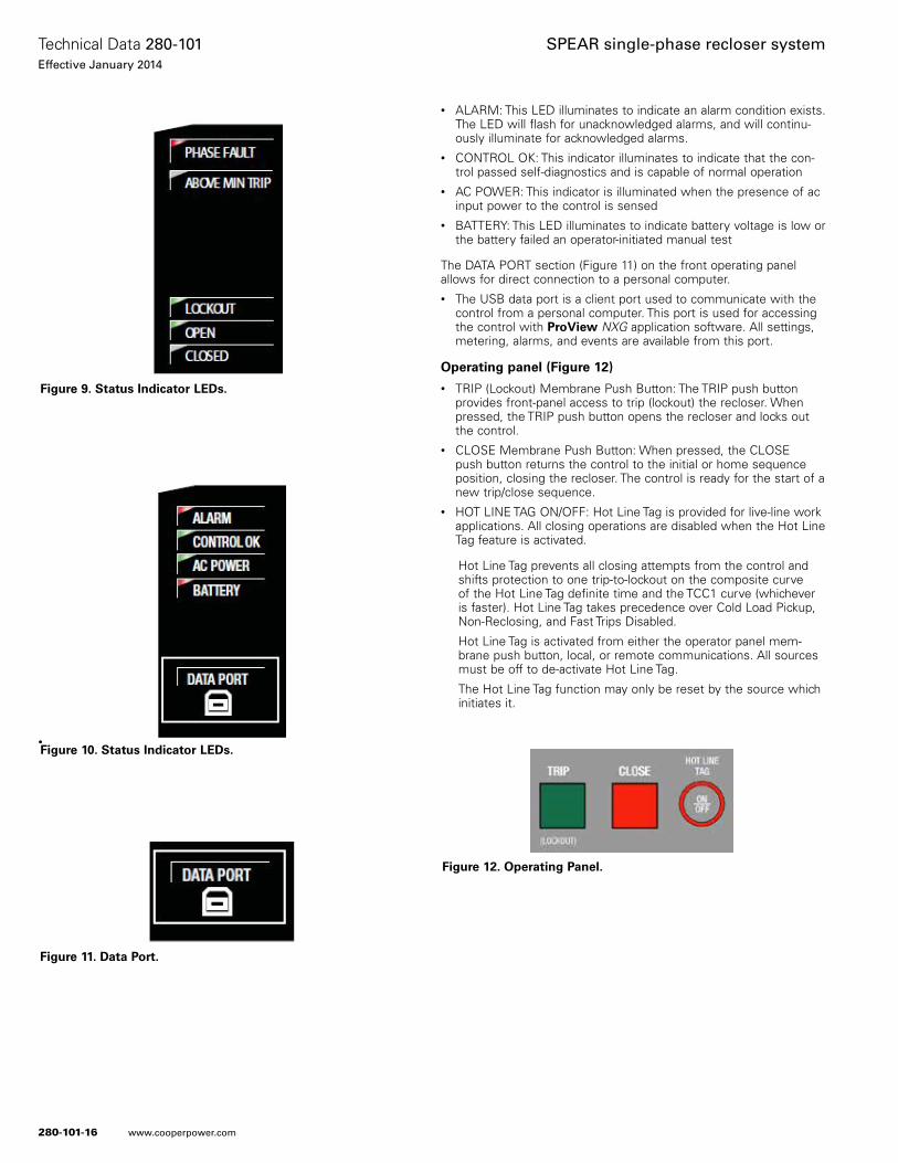
280-101-16
Technical Data 280-101Effective January 2014
SPEAR single-phase recloser system
www.cooperpower.com
•
• ALARM: This LED illuminates to indicate an alarm condition exists . The LED will flash for unacknowledged alarms, and will continu-ously illuminate for acknowledged alarms .
• CONTROL OK: This indicator illuminates to indicate that the con-trol passed self-diagnostics and is capable of normal operation
• AC POWER: This indicator is illuminated when the presence of ac input power to the control is sensed
• BATTERY: This LED illuminates to indicate battery voltage is low or the battery failed an operator-initiated manual test
The DATA PORT section (Figure 11) on the front operating panel allows for direct connection to a personal computer .• The USB data port is a client port used to communicate with the
control from a personal computer . This port is used for accessing the control with ProView NXG application software . All settings, metering, alarms, and events are available from this port .
Operating panel (Figure 12)
• TRIP (Lockout) Membrane Push Button: The TRIP push button provides front-panel access to trip (lockout) the recloser . When pressed, the TRIP push button opens the recloser and locks out the control .
• CLOSE Membrane Push Button: When pressed, the CLOSE push button returns the control to the initial or home sequence position, closing the recloser . The control is ready for the start of a new trip/close sequence .
• HOT LINE TAG ON/OFF: Hot Line Tag is provided for live-line work applications . All closing operations are disabled when the Hot Line Tag feature is activated .
Hot Line Tag prevents all closing attempts from the control and shifts protection to one trip-to-lockout on the composite curve of the Hot Line Tag definite time and the TCC1 curve (whichever is faster) . Hot Line Tag takes precedence over Cold Load Pickup, Non-Reclosing, and Fast Trips Disabled .
Hot Line Tag is activated from either the operator panel mem-brane push button, local, or remote communications . All sources must be off to de-activate Hot Line Tag .
The Hot Line Tag function may only be reset by the source which initiates it .
Figure 10. Status Indicator LEDs.
Figure 11. Data Port.
Figure 12. Operating Panel.
Figure 9. Status Indicator LEDs.
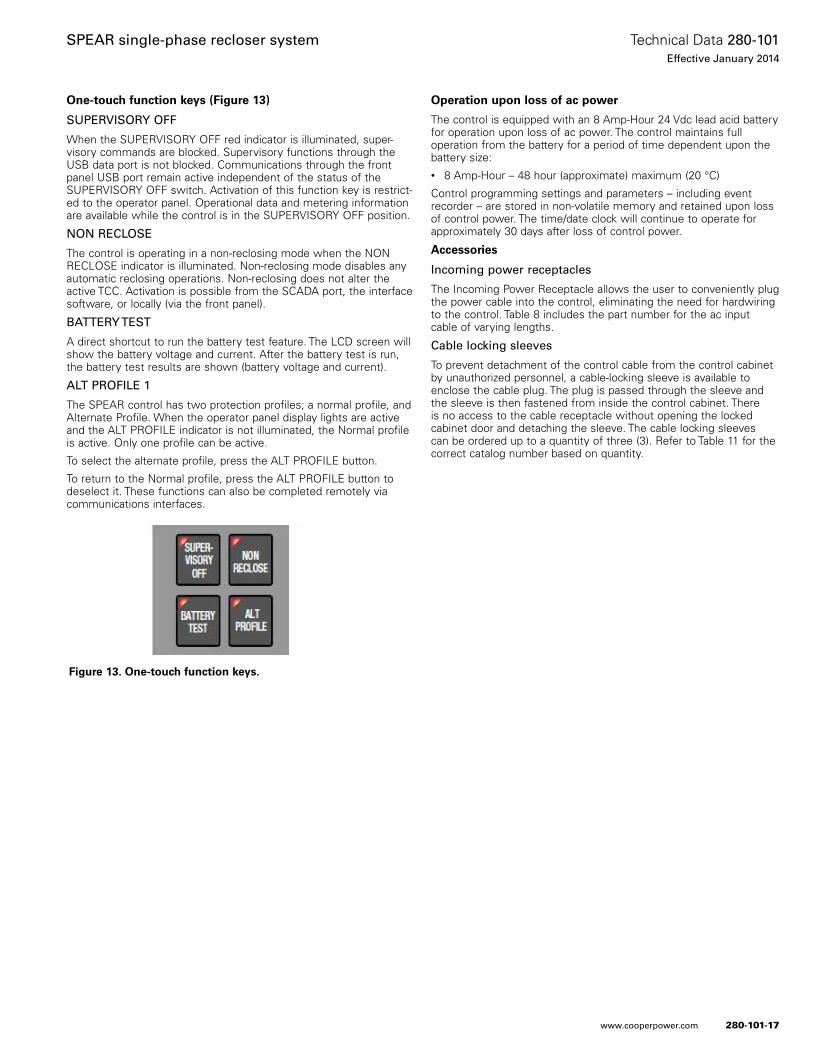
280-101-17
Technical Data 280-101Effective January 2014
SPEAR single-phase recloser system
www.cooperpower.com
One-touch function keys (Figure 13)
SUPERVISORY OFF
When the SUPERVISORY OFF red indicator is illuminated, super-visory commands are blocked . Supervisory functions through the USB data port is not blocked . Communications through the front panel USB port remain active independent of the status of the SUPERVISORY OFF switch . Activation of this function key is restrict-ed to the operator panel . Operational data and metering information are available while the control is in the SUPERVISORY OFF position .
NON RECLOSE
The control is operating in a non-reclosing mode when the NON RECLOSE indicator is illuminated . Non-reclosing mode disables any automatic reclosing operations . Non-reclosing does not alter the active TCC . Activation is possible from the SCADA port, the interface software, or locally (via the front panel) .
BATTERY TEST
A direct shortcut to run the battery test feature . The LCD screen will show the battery voltage and current . After the battery test is run, the battery test results are shown (battery voltage and current) .
ALT PROFILE 1
The SPEAR control has two protection profiles; a normal profile, and Alternate Profile . When the operator panel display lights are active and the ALT PROFILE indicator is not illuminated, the Normal profile is active . Only one profile can be active .
To select the alternate profile, press the ALT PROFILE button .
To return to the Normal profile, press the ALT PROFILE button to deselect it . These functions can also be completed remotely via communications interfaces .
Operation upon loss of ac power
The control is equipped with an 8 Amp-Hour 24 Vdc lead acid battery for operation upon loss of ac power . The control maintains full operation from the battery for a period of time dependent upon the battery size:• 8 Amp-Hour – 48 hour (approximate) maximum (20 °C)
Control programming settings and parameters – including event recorder – are stored in non-volatile memory and retained upon loss of control power . The time/date clock will continue to operate for approximately 30 days after loss of control power .
Accessories
Incoming power receptacles
The Incoming Power Receptacle allows the user to conveniently plug the power cable into the control, eliminating the need for hardwiring to the control . Table 8 includes the part number for the ac input cable of varying lengths .
Cable locking sleeves
To prevent detachment of the control cable from the control cabinet by unauthorized personnel, a cable-locking sleeve is available to enclose the cable plug . The plug is passed through the sleeve and the sleeve is then fastened from inside the control cabinet . There is no access to the cable receptacle without opening the locked cabinet door and detaching the sleeve . The cable locking sleeves can be ordered up to a quantity of three (3) . Refer to Table 11 for the correct catalog number based on quantity .
Figure 13. One-touch function keys.
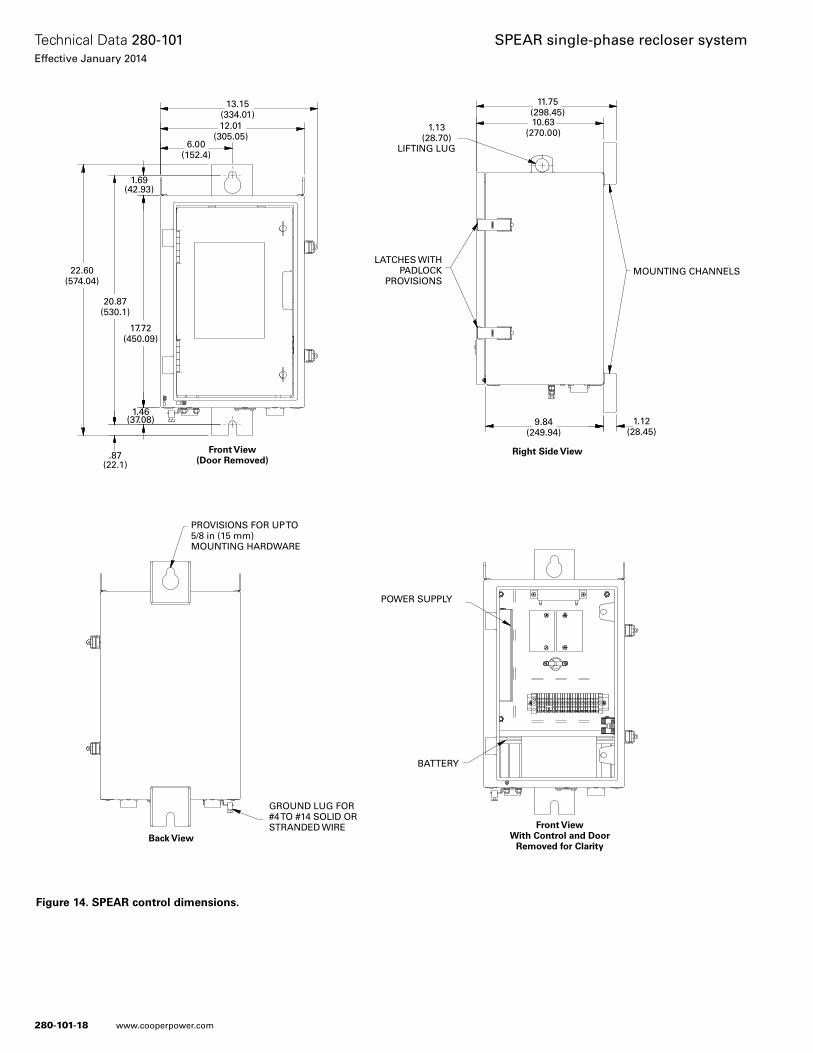
280-101-18
Technical Data 280-101Effective January 2014
SPEAR single-phase recloser system
www.cooperpower.com
13.15(334.01)12.01
(305.05)6.00
(152.4)
1.69(42.93)
22.60(574.04)
20.87(530.1)
17.72(450.09)
1.46(37.08)
.87(22.1)
PROVISIONS FOR UP TO 5/8 in (15 mm) MOUNTING HARDWARE
GROUND LUG FOR #4 TO #14 SOLID OR STRANDED WIRE
Back View
Front View(Door Removed)
Right Side View
Front ViewWith Control and Door
Removed for Clarity
POWER SUPPLY
BATTERY
MOUNTING CHANNELSLATCHES WITH
PADLOCK PROVISIONS
LIFTING LUG
11.75(298.45)10.63
(270.00)1.13(28.70)
9.84(249.94)
1.12(28.45)
Figure 14. SPEAR control dimensions.
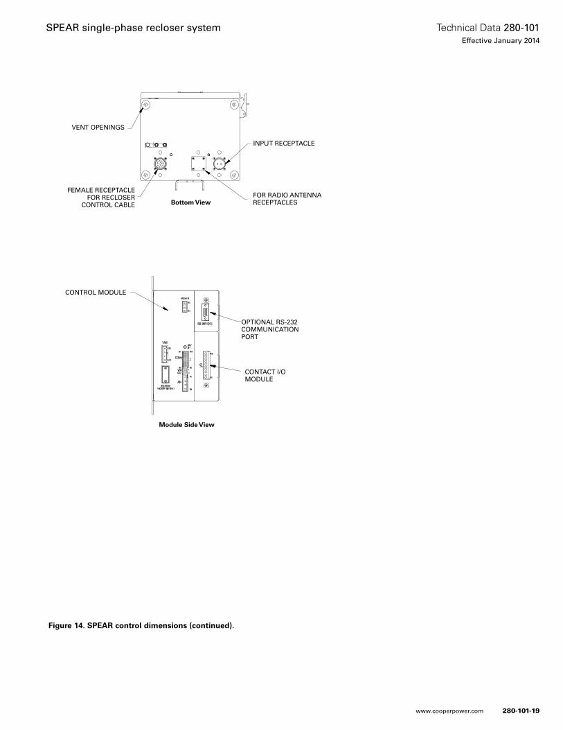
280-101-19
Technical Data 280-101Effective January 2014
SPEAR single-phase recloser system
www.cooperpower.com
VENT OPENINGS
FEMALE RECEPTACLE FOR RECLOSER
CONTROL CABLE
FOR RADIO ANTENNA RECEPTACLES
INPUT RECEPTACLE
Bottom View
Module Side View
CONTROL MODULE
OPTIONAL RS-232 COMMUNICATION PORT
CONTACT I/O MODULE
Figure 14. SPEAR control dimensions (continued).
Eaton, Cooper Power Systems, ProView, and SPEAR are valuable trademarks of Eaton, in the U.S. and other countries. You are not permitted to use these trademarks without the prior written consent of Eaton.
SPEAR single-phase recloser system
Eaton1000 Eaton BoulevardCleveland, OH 44122United StatesEaton.com
Eaton’s Cooper Power Systems Business2300 Badger DriveWaukesha, WI 53188United StatesCooperpower.com
© 2014 EatonAll Rights ReservedPrinted in USAPublication No. 280-101January 2014
Technical Data 280-101Effective January 2014
For Eaton’s Cooper Power Systems SPEAR recloser system product information call 1-877-277-4636 or visit: www.cooperpower.com.
280-101-20

DescriptionThe Form 4D recloser control is the first in a line of fully integrated controls developed by Eaton’s Cooper Power Systems. These controls will feature a standard look and feel, and a universal platform that can be programmed for almost any protective application. This means one standard operating system and front panel to train field technicians on. That translates to fewer training expenses, reduced inventory, and a distribution system that is much easier to maintain.
In addition to the flexible and user-friendly platform, the new Eaton’s Cooper Power Systems controls will have the communications technology to take your system into the future. With fully modular communication compatibility, these controls will support cellular and radio communications utilizing the DNP3 and other serial and network protocols. Side panel RS-232, fiber-optic, Ethernet, and RS-485 ports are available for connection to SCADA or other devices. These ports are accessed by swinging the control panel forward.
The Form 4D recloser control provides phase and ground current sensing, and three-phase voltage sensing. The Form 4D control can compute power, energy, power factor, and power flow direction from these current and voltage inputs.
The standardized front panel of the Form 4D control can be used to program and interrogate the control, as well as to display metering and alarm information. Control parameters can also be programmed via personal computer using ProView NXG™ interface software. Temporary connection to the control can be made through the front panel USB port. The ProView NXG interface software includes the functionality to create and modify time-current curves (TCCs), and provides diagnostic information. The Form 4D control analysis tools include event recording, data profiling, and various metering capabilities.
Form 4D microprocessor-based recloser control and accessories
280-104-1
Technical Data 280-104Effective April 2014Supersedes May 2011
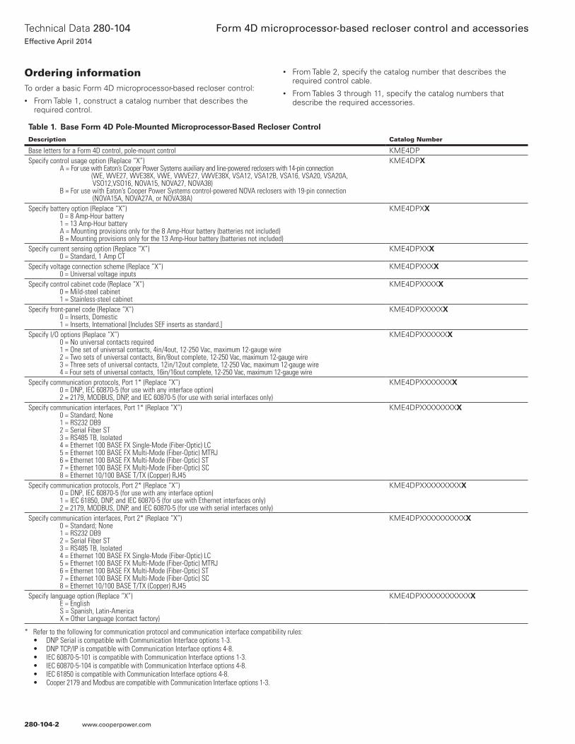
Ordering informationTo order a basic Form 4D microprocessor-based recloser control:• From Table 1, construct a catalog number that describes the
required control.
• From Table 2, specify the catalog number that describes the required control cable.
• From Tables 3 through 11, specify the catalog numbers that describe the required accessories.
Table 1. Base Form 4D Pole-Mounted Microprocessor-Based Recloser Control
Description Catalog Number
Base letters for a Form 4D control, pole-mount control KME4DPSpecify control usage option (Replace “X”) A = For use with Eaton’s Cooper Power Systems auxiliary and line-powered reclosers with 14-pin connection (WE, WVE27, WVE38X, VWE, VWVE27, VWVE38X, VSA12, VSA12B, VSA16, VSA20, VSA20A, VSO12,VSO16, NOVA15, NOVA27, NOVA38) B = For use with Eaton’s Cooper Power Systems control-powered NOVA reclosers with 19-pin connection (NOVA15A, NOVA27A, or NOVA38A)
KME4DPX
Specify battery option (Replace “X”) 0 = 8 Amp-Hour battery 1 = 13 Amp-Hour battery A = Mounting provisions only for the 8 Amp-Hour battery (batteries not included) B = Mounting provisions only for the 13 Amp-Hour battery (batteries not included)
KME4DPXX
Specify current sensing option (Replace “X”) 0 = Standard, 1 Amp CT
KME4DPXXX
Specify voltage connection scheme (Replace “X”) 0 = Universal voltage inputs
KME4DPXXXX
Specify control cabinet code (Replace “X”) 0 = Mild-steel cabinet 1 = Stainless-steel cabinet
KME4DPXXXXX
Specify front-panel code (Replace “X”) 0 = Inserts, Domestic 1 = Inserts, International [Includes SEF inserts as standard.]
KME4DPXXXXXX
Specify I/O options (Replace “X”) 0 = No universal contacts required 1 = One set of universal contacts, 4in/4out, 12-250 Vac, maximum 12-gauge wire 2 = Two sets of universal contacts, 8in/8out complete, 12-250 Vac, maximum 12-gauge wire 3 = Three sets of universal contacts, 12in/12out complete, 12-250 Vac, maximum 12-gauge wire 4 = Four sets of universal contacts, 16in/16out complete, 12-250 Vac, maximum 12-gauge wire
KME4DPXXXXXXX
Specify communication protocols, Port 1* (Replace “X”) 0 = DNP, IEC 60870-5 (for use with any interface option) 2 = 2179, MODBUS, DNP, and IEC 60870-5 (for use with serial interfaces only)
KME4DPXXXXXXXX
Specify communication interfaces, Port 1* (Replace “X”) 0 = Standard; None 1 = RS232 DB9 2 = Serial Fiber ST 3 = RS485 TB, Isolated 4 = Ethernet 100 BASE FX Single-Mode (Fiber-Optic) LC 5 = Ethernet 100 BASE FX Multi-Mode (Fiber-Optic) MTRJ 6 = Ethernet 100 BASE FX Multi-Mode (Fiber-Optic) ST 7 = Ethernet 100 BASE FX Multi-Mode (Fiber-Optic) SC 8 = Ethernet 10/100 BASE T/TX (Copper) RJ45
KME4DPXXXXXXXXX
Specify communication protocols, Port 2* (Replace “X”) 0 = DNP, IEC 60870-5 (for use with any interface option) 1 = IEC 61850, DNP, and IEC 60870-5 (for use with Ethernet interfaces only) 2 = 2179, MODBUS, DNP, and IEC 60870-5 (for use with serial interfaces only)
KME4DPXXXXXXXXXX
Specify communication interfaces, Port 2* (Replace “X”) 0 = Standard; None 1 = RS232 DB9 2 = Serial Fiber ST 3 = RS485 TB, Isolated 4 = Ethernet 100 BASE FX Single-Mode (Fiber-Optic) LC 5 = Ethernet 100 BASE FX Multi-Mode (Fiber-Optic) MTRJ 6 = Ethernet 100 BASE FX Multi-Mode (Fiber-Optic) ST 7 = Ethernet 100 BASE FX Multi-Mode (Fiber-Optic) SC 8 = Ethernet 10/100 BASE T/TX (Copper) RJ45
KME4DPXXXXXXXXXXX
Specify language option (Replace “X”) E = English S = Spanish, Latin-America X = Other Language (contact factory)
KME4DPXXXXXXXXXXXX
* Refer to the following for communication protocol and communication interface compatibility rules:• DNP Serial is compatible with Communication Interface options 1-3.• DNP TCP/IP is compatible with Communication Interface options 4-8.• IEC 60870-5-101 is compatible with Communication Interface options 1-3.• IEC 60870-5-104 is compatible with Communication Interface options 4-8.• IEC 61850 is compatible with Communication Interface options 4-8.• Cooper 2179 and Modbus are compatible with Communication Interface options 1-3.
280-104-2
Technical Data 280-104Effective April 2014
Form 4D microprocessor-based recloser control and accessories
www.cooperpower.com
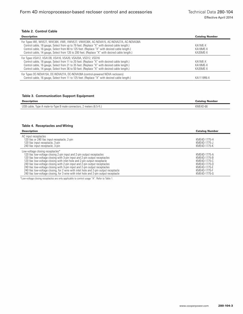
Table 4. Receptacles and Wiring
Description Catalog Number
AC input receptacles 120 Vac or 240 Vac input receptacle, 2-pin 120 Vac input receptacle, 3-pin 240 Vac input receptacle, 3-pin
KME4D-1775-HKME4D-1775-JKME4D-1775-K
Low-voltage closing receptacles* 120 Vac low-voltage closing 2-pin input and 2-pin output receptacles 120 Vac low-voltage closing with 3-pin input and 2-pin output receptacles 120 Vac low-voltage closing with inlet hole and 2-pin output receptacle 240 Vac low-voltage closing with 2-pin input and 2-pin output receptacles 240 Vac low-voltage closing with 3-pin input and 2-pin output receptacles 240 Vac low-voltage closing, for 2 wire with inlet hole and 2-pin output receptacle 240 Vac low-voltage closing, for 3 wire with inlet hole and 2-pin output receptacle
KME4D-1775-AKME4D-1775-BKME4D-1775-CKME4D-1775-DKME4D-1775-EKME4D-1775-FKME4D-1775-G
Table 3. Communication Support Equipment
Description Catalog Number
USB cable, Type A male-to-Type B male connectors, 2 meters (6.5-ft.) KME4D-66
Table 2. Control Cable
Description Catalog Number
For Types WE, WVE27, WVE38X, VWE, VWVE27, VWVE38X, AC-NOVA15, AC-NOVA27A, AC-NOVA38A Control cable, 18 gauge, Select from up to 79 feet. (Replace “X” with desired cable length.) Control cable, 16 gauge, Select from 80 to 125 feet. (Replace “X” with desired cable length.) Control cable, 14 gauge, Select from 126 to 200 feet. (Replace “X” with desired cable length.)
KA1ME-XKA18ME-XKA35ME-X
For Types VSA12, VSA12B, VSA16, VSA20, VSA20A, VSO12, VSO16 Control cable, 18 gauge, Select from 11 to 20 feet. (Replace “X” with desired cable length.) Control cable, 16 gauge, Select from 21 to 35 feet. (Replace “X” with desired cable length.) Control cable, 14 gauge, Select from 36 to 50 feet. (Replace “X” with desired cable length.)
KA1ME-XKA18ME-XKA35ME-X
For Types DC-NOVA15A, DC-NOVA27A, DC-NOVA38A (control-powered NOVA reclosers) Control cable, 16 gauge, Select from 11 to 125 feet. (Replace “X” with desired cable length.) KA1119R6-X
*Low-voltage closing receptacles are only applicable to control usage “A”. Refer to Table 1.
280-104-3
Technical Data 280-104Effective April 2014
Form 4D microprocessor-based recloser control and accessories
www.cooperpower.com
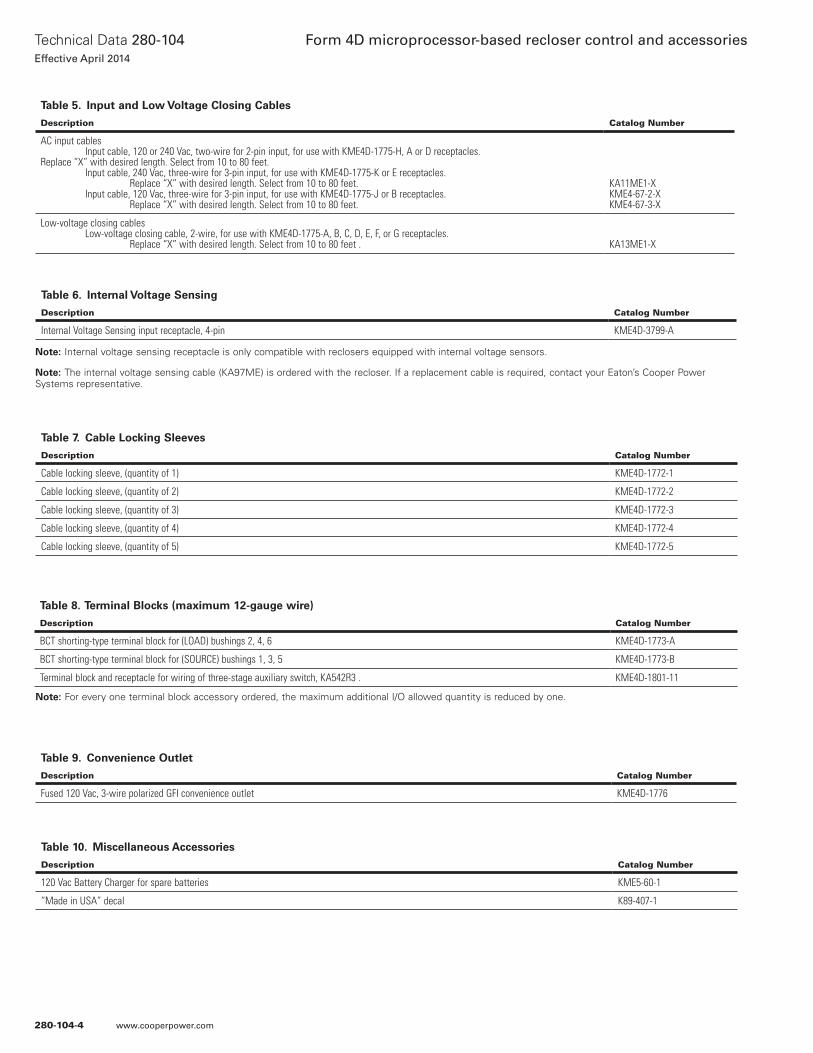
Table 5. Input and Low Voltage Closing Cables
Description Catalog Number
AC input cables Input cable, 120 or 240 Vac, two-wire for 2-pin input, for use with KME4D-1775-H, A or D receptacles. Replace “X” with desired length. Select from 10 to 80 feet. Input cable, 240 Vac, three-wire for 3-pin input, for use with KME4D-1775-K or E receptacles. Replace “X” with desired length. Select from 10 to 80 feet. Input cable, 120 Vac, three-wire for 3-pin input, for use with KME4D-1775-J or B receptacles. Replace “X” with desired length. Select from 10 to 80 feet.
KA11ME1-XKME4-67-2-XKME4-67-3-X
Low-voltage closing cables Low-voltage closing cable, 2-wire, for use with KME4D-1775-A, B, C, D, E, F, or G receptacles. Replace “X” with desired length. Select from 10 to 80 feet . KA13ME1-X
Table 7. Cable Locking Sleeves
Description Catalog Number
Cable locking sleeve, (quantity of 1) KME4D-1772-1
Cable locking sleeve, (quantity of 2) KME4D-1772-2
Cable locking sleeve, (quantity of 3) KME4D-1772-3
Cable locking sleeve, (quantity of 4) KME4D-1772-4
Cable locking sleeve, (quantity of 5) KME4D-1772-5
Table 9. Convenience Outlet
Description Catalog Number
Fused 120 Vac, 3-wire polarized GFI convenience outlet KME4D-1776
Table 10. Miscellaneous Accessories
Description Catalog Number
120 Vac Battery Charger for spare batteries KME5-60-1
“Made in USA” decal K89-407-1
Table 8. Terminal Blocks (maximum 12-gauge wire)
Description Catalog Number
BCT shorting-type terminal block for (LOAD) bushings 2, 4, 6 KME4D-1773-A
BCT shorting-type terminal block for (SOURCE) bushings 1, 3, 5 KME4D-1773-B
Terminal block and receptacle for wiring of three-stage auxiliary switch, KA542R3 . KME4D-1801-11
otee:N For every one terminal block accessory ordered, the maximum additional I/O allowed quantity is reduced by one.
Table 6. Internal Voltage Sensing
Description Catalog Number
Internal Voltage Sensing input receptacle, 4-pin KME4D-3799-A
otee:N Internal voltage sensing receptacle is only compatible with reclosers equipped with internal voltage sensors.
otee:N The internal voltage sensing cable (KA97ME) is ordered with the recloser. If a replacement cable is required, contact your Eaton’s Cooper Power Systems representative.
280-104-4
Technical Data 280-104Effective April 2014
Form 4D microprocessor-based recloser control and accessories
www.cooperpower.com
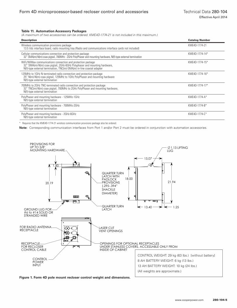
Figure 1. Form 4D pole mount recloser control weight and dimensions.
20.19
1.45
PROVISIONS FORUP TO 5/8"MOUNTING HARDWARE.
QUARTER TURNLATCH WITHPADLOCKPROVISIONS
QUARTER TURNLATCH GROUND LUG FOR
#6 to #14 SOLID ORSTRANDED WIRE
LASER CUT VENT OPENINGS
OPENINGS FOR OPTIONAL RECEPTACLESUNDER STAINLESS COVERS, ACCESSABLE ONLY FROMINSIDE OF CABINET
FOR RADIO ANTENNARECEPTACLE
CONTROL POWER INPUT
RECEPTACLEFOR RECLOSERCONTROL CABLE
21.9418.00
13.40 1.25
15.07
1.13 LIFTINGLUG
(.295-.394” SHACKLEDIAMETER)
CONTROL WEIGHT: 29 kg (63 lbs.) [without battery]
8 AH BATTERY WEIGHT: 6 kg (13 lbs.)
13 AH BATTERY WEIGHT: 10 kg (24 lbs.)
(All weights are approximate.)
* Requires that the KME4D-1774-21 wireless communication provisions package also be ordered.
Notee: Corresponding communication interfaces from Port 1 and/or Port 2 must be ordered in conjunction with automation accessories.
Table 11. Automation Accessory Packages(A maximum of two accessories can be ordered. KME4D-1774-21 is not included in this maximum.)
Description Catalog Number
Wireless communication provisions package 13.5 Vdc interface board, radio mounting tray (Radio and communications interface cards not included)
KME4D-1774-21
Cellular communications connection and protection package 32” SMA(m)-N(m) coax pigtail, 700MHz - 2GHz PolyPhaser and mounting hardware, N(f)-type external termination
KME4D-1774-14*
WiFi/WiMax communications connection and protection package 32” SMA(m)-N(m) coax pigtail, 2GHz-6GHz Polyphaser and mounting hardware, N(f)-type external termination, TNC(m)-SMA(m) in-line coaxial adapter
KME4D-1774-15*
125MHz to 1GHz N-terminated radio connection and protection package 25” N(m)-N(m) coax pigtail, 125MHz to 1GHz PolyPhaser and mounting hardware N(f)-type external termination
KME4D-1774-16*
700MHz to 2GHz TNC-terminated radio connection and protection package 32” TNC(m)-N(m) coax pigtail, 700MHz to 2GHz PolyPhaser and mounting hardware, N(f)-type external termination
KME4D-1774-17*
PolyPhaser and mounting hardware - 125MHz-1GHz N(f)-type external termination
KME4D-1774-A*
PolyPhaser and mounting hardware - 700MHz-2GHz N(f)-type external termination
KME4D-1774-B*
PolyPhaser and mounting hardware - 2GHz-6GHz N(f)-type external termination
KME4D-1774-C*
280-104-5
Technical Data 280-104Effective April 2014
Form 4D microprocessor-based recloser control and accessories
www.cooperpower.com
Control featuresControl security
The Form 4D recloser control has multiple customer-programmable security codes to limit control programming and viewing function access to authorized personnel. The Form 4D control is capable of supporting strong passwords containing letters (upper and lower case), numbers, and symbols. The front panel Human-Machine Interface (HMI) includes a user-selected security code to access the settings. Plus, the ProView NXG interface software has its own security levels for multiple-user access.
Protection profiles
The Form 4D control provides two protection profiles, each capable of fully specifying the operation of the control. The protection profiles are selectable through the front-panel push-button interface or through the interface software and USB communication ports. Each protection profile contains overcurrent protection, voltage protection, frequency protection, sync check, sensitive earth fault protection, and operation settings.
Reclosing and overcurrent protection/TCCs
The Form 4D control offers flexible phase and ground overcurrent protection which can be programmed with up to four operations-to-lockout. Each time-current curve (TCC) can be individually programmed from up to fifty standard curves which can be further customized. Time-current curves are available for fast and delayed operations. The time-current curves are also selectable from a graphical TCC editor to visualize any modifications prior to configuring the control. Reclose intervals and reset time can also be programmed by the user.
TCC editor II
Coordination and actual time current modifications are available with a graphic, interactive TCC editor. The TCC Editor II includes a complete database of standard recloser industry time current curves, both ANSI® and IEC types, along with the ability to customize the TCCs with multipliers, constant time adders, or minimum response time adders. The user is also able to derive their own specific TCC through data point entry.
Sensitive earth fault
The Form 4D control includes Sensitive Earth Fault (SEF) protection, which will provide tripping of the recloser for ground currents below normal ground minimum trip elements. The SEF feature has programmable operations-to-lockout and reclose intervals independent of the ground settings and is independently selectable for each protection profile.
High current lockout
The High Current Lockout (HCL) feature will automatically lockout the control when the current exceeds a programmed threshold. The active number of operations-to-lockout is selectable for both phase and ground and is independently selectable for each protection profile.
Cold load pickup
The Form 4D control provides a Cold Load Pickup (CLPU) feature that will prevent the control from tripping due to short-term increases in current caused by loss of normal load diversity or feeder inrush. This feature has an independently programmable minimum trip value, time-current curve, reclose interval, and number of operations to lockout for each protection profile as well as for both phase and ground. The CLPU feature will also inhibit ‘normal’ overcurrent protection during the CLPU active time.
Hot line tag
The Form 4D includes a Hot Line Tag (HLT) switch that will block all Close operations, local or remote, for live-line work. The control will trip on one operation-to-lockout on the composite curve of the HLT definite time and the TCC1 curve, whichever is faster, when HLT is active. Hot Line Tag takes precedence over Cold Load Pickup, Non-Reclosing, and Fast Trips Disabled. The Hot Line Tag time delay is independently selectable for each protection profile.
Fast trips disabled
The Fast Trips Disabled feature will ignore the normal TCCs and number of trips and instead use the Fast Trips Disabled settings when Fast Trips Disabled is active. Fast Trips Disabled will have separate phase and ground settings and is independently selectable for each protection profile.
Ground trip precedence
The Form 4D control comes equipped with an option for Ground Trip Precedence. When ground trip precedence is selected to be active, the sequence uses the ground operations to lockout for fault current above both phase and ground minimum trip values.
Voltage protection
The Form 4D control includes three levels each of over- and undervoltage protection and includes single-phase and three-phase protection for both over- and undervoltage conditions. Both functions include a phase pickup, a phase time delay, a three-phase pickup, and three-phase time delay. One overvoltage and one undervoltage alarm is also provided.
Frequency protection
Six levels of frequency protection are included with the control, with each level configurable as either overfrequency or underfrequency. A frequency restoration function, which can be enabled or disabled, will allow the recloser to automatically close should the frequency return to within configured settings for a user-settable time.
Sync check
The Form 4D control includes sync check functionality, which is used to qualify any close signal to the recloser when enabled via the sync check settings. Sync check allows for closing for any combination of dead/live bus/line, and to perform anticipatory closing for a live bus/live line condition by calculating slip and anticipating the mechanism closing delay. In addition to the anticipatory close calculation, the sync check system performs verification of line and bus voltage magnitudes and frequencies to determine that they are within pre-determined ranges, and that the angular differences between the two systems is also within the pre-determined range.
Sequence coordination
The Form 4D control Sequence Coordination feature will allow the control to step through selected operations in the operating sequence without tripping when a down-line recloser is proceeding through its reclose sequence. The number of advances is programmable from one to three operations to provide trip coordination with the down-line recloser.
280-104-6
Technical Data 280-104Effective April 2014
Form 4D microprocessor-based recloser control and accessories
www.cooperpower.com
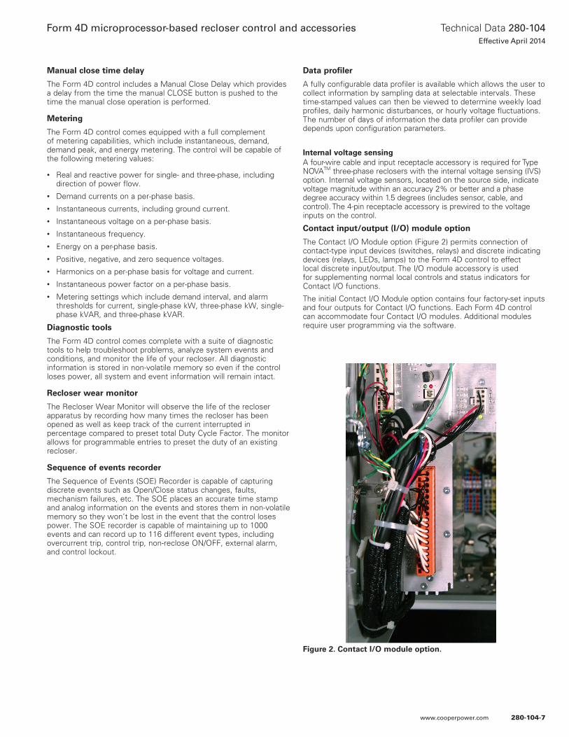
Manual close time delay
The Form 4D control includes a Manual Close Delay which provides a delay from the time the manual CLOSE button is pushed to the time the manual close operation is performed.
Metering
The Form 4D control comes equipped with a full complement of metering capabilities, which include instantaneous, demand, demand peak, and energy metering. The control will be capable of the following metering values:
• Real and reactive power for single- and three-phase, including direction of power flow.
• Demand currents on a per-phase basis.• Instantaneous currents, including ground current.• Instantaneous voltage on a per-phase basis.• Instantaneous frequency.• Energy on a per-phase basis.• Positive, negative, and zero sequence voltages.• Harmonics on a per-phase basis for voltage and current.• Instantaneous power factor on a per-phase basis.• Metering settings which include demand interval, and alarm
thresholds for current, single-phase kW, three-phase kW, single-phase kVAR, and three-phase kVAR.
Diagnostic tools
The Form 4D control comes complete with a suite of diagnostic tools to help troubleshoot problems, analyze system events and conditions, and monitor the life of your recloser. All diagnostic information is stored in non-volatile memory so even if the control loses power, all system and event information will remain intact.
Recloser wear monitor
The Recloser Wear Monitor will observe the life of the recloser apparatus by recording how many times the recloser has been opened as well as keep track of the current interrupted in percentage compared to preset total Duty Cycle Factor. The monitor allows for programmable entries to preset the duty of an existing recloser.
Sequence of events recorder
The Sequence of Events (SOE) Recorder is capable of capturing discrete events such as Open/Close status changes, faults, mechanism failures, etc. The SOE places an accurate time stamp and analog information on the events and stores them in non-volatile memory so they won’t be lost in the event that the control loses power. The SOE recorder is capable of maintaining up to 1000 events and can record up to 116 different event types, including overcurrent trip, control trip, non-reclose ON/OFF, external alarm, and control lockout.
Data profiler
A fully configurable data profiler is available which allows the user to collect information by sampling data at selectable intervals. These time-stamped values can then be viewed to determine weekly load profiles, daily harmonic disturbances, or hourly voltage fluctuations. The number of days of information the data profiler can provide depends upon configuration parameters.
Internal voltage sensingA four-wire cable and input receptacle accessory is required for Type NOVATM three-phase reclosers with the internal voltage sensing (IVS) option. Internal voltage sensors, located on the source side, indicate voltage magnitude within an accuracy 2% or better and a phase degree accuracy within 1.5 degrees (includes sensor, cable, and control). The 4-pin receptacle accessory is prewired to the voltage inputs on the control.
Contact input/output (I/O) module option
The Contact I/O Module option (Figure 2) permits connection of contact-type input devices (switches, relays) and discrete indicating devices (relays, LEDs, lamps) to the Form 4D control to effect local discrete input/output. The I/O module accessory is used for supplementing normal local controls and status indicators for Contact I/O functions.
The initial Contact I/O Module option contains four factory-set inputs and four outputs for Contact I/O functions. Each Form 4D control can accommodate four Contact I/O modules. Additional modules require user programming via the software.
Figure 2. Contact I/O module option.
280-104-7
Technical Data 280-104Effective April 2014
Form 4D microprocessor-based recloser control and accessories
www.cooperpower.com
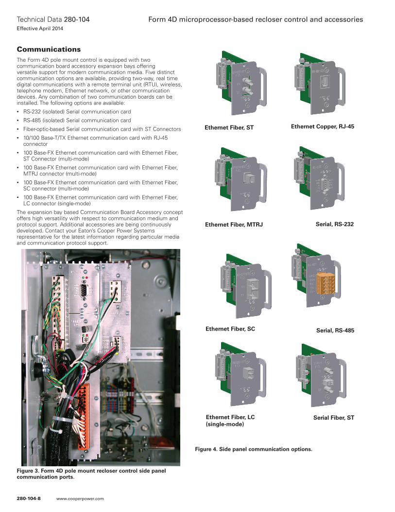
CommunicationsThe Form 4D pole mount control is equipped with two communication board accessory expansion bays offering versatile support for modern communication media. Five distinct communication options are available, providing two-way, real time digital communications with a remote terminal unit (RTU), wireless, telephone modem, Ethernet network, or other communication devices. Any combination of two communication boards can be installed. The following options are available:• RS-232 (isolated) Serial communication card• RS-485 (isolated) Serial communication card• Fiber-optic-based Serial communication card with ST Connectors• 10/100 Base-T/TX Ethernet communication card with RJ-45
connector• 100 Base-FX Ethernet communication card with Ethernet Fiber,
ST Connector (multi-mode)• 100 Base-FX Ethernet communication card with Ethernet Fiber,
MTRJ connector (multi-mode)• 100 Base-FX Ethernet communication card with Ethernet Fiber,
SC connector (multi-mode)• 100 Base-FX Ethernet communication card with Ethernet Fiber,
LC connector (single-mode)
The expansion bay based Communication Board Accessory concept offers high versatility with respect to communication medium and protocol support. Additional accessories are being continuously developed. Contact your Eaton’s Cooper Power Systems representative for the latest information regarding particular media and communication protocol support.
Figure 3. Form 4D pole mount recloser control side panel communication ports.
Figure 4. Side panel communication options.
Ethernet Copper, RJ-45Ethernet Fiber, ST
Ethernet Fiber, MTRJ Serial, RS-232
Ethernet Fiber, LC (single-mode)
Serial, RS-485Ethernet Fiber, SC
Serial Fiber, ST
280-104-8
Technical Data 280-104Effective April 2014
Form 4D microprocessor-based recloser control and accessories
www.cooperpower.com
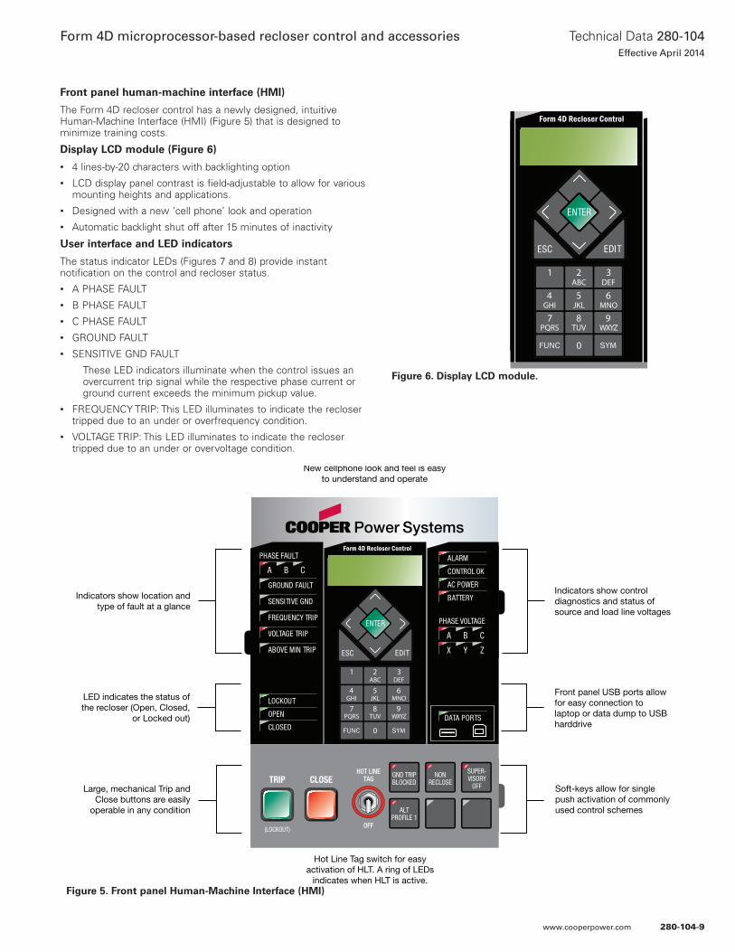
Front panel human-machine interface (HMI)
The Form 4D recloser control has a newly designed, intuitive Human-Machine Interface (HMI) (Figure 5) that is designed to minimize training costs.
Display LCD module (Figure 6)
• 4 lines-by-20 characters with backlighting option• LCD display panel contrast is field-adjustable to allow for various
mounting heights and applications.• Designed with a new ‘cell phone’ look and operation• Automatic backlight shut off after 15 minutes of inactivity
User interface and LED indicators
The status indicator LEDs (Figures 7 and 8) provide instant notification on the control and recloser status.• A PHASE FAULT• B PHASE FAULT• C PHASE FAULT• GROUND FAULT• SENSITIVE GND FAULT
These LED indicators illuminate when the control issues an overcurrent trip signal while the respective phase current or ground current exceeds the minimum pickup value.
• FREQUENCY TRIP: This LED illuminates to indicate the recloser tripped due to an under or overfrequency condition.
• VOLTAGE TRIP: This LED illuminates to indicate the recloser tripped due to an under or overvoltage condition.
New cellphone look and feel is easyto understand and operate
Indicators show location andtype of fault at a glance
LED indicates the status ofthe recloser (Open, Closed,
or Locked out)
Large, mechanical Trip andClose buttons are easily
operable in any condition
Indicators show controldiagnostics and status ofsource and load line voltages
Front panel USB ports allowfor easy connection tolaptop or data dump to USBharddrive
Soft-keys allow for singlepush activation of commonlyused control schemes
Hot Line Tag switch for easyactivation of HLT. A ring of LEDs
indicates when HLT is active.
DATA PORTS
ENTER
EDITESC
PHASE FAULT
A B C
GROUND FAULT
ABOVE MIN TRIP
LOCKOUT
OPEN
CLOSED
VOLTAGE TRIP
FREQUENCY TRIP
SENSITIVE GND
A B C
X Y Z
PHASE VOLTAGE
ALARM
BATTERY
AC POWER
CONTROL OK
ALTPROFILE 1
GND TRIPBLOCKED
NONRECLOSE
SUPER-VISORY
OFF
HOT LINETAGTRIP
OFF(LOCKOUT)
CLOSE
Figure 5. Front panel Human-Machine Interface (HMI)
DATA PORTS
ENTER
EDITESC
PHASE FAULT
A B C
GROUND FAULT
ABOVE MIN TRIP
LOCKOUT
OPEN
CLOSED
VOLTAGE TRIP
FREQUENCY TRIP
SENSITIVE GND
A B C
X Y Z
PHASE VOLTAGE
ALARM
BATTERY
AC POWER
CONTROL OK
ALTPROFILE 1
GND TRIPBLOCKED
NONRECLOSE
SUPER-VISORY
OFF
HOT LINETAGTRIP
OFF(LOCKOUT)
CLOSE
Figure 6. Display LCD module.
280-104-9
Technical Data 280-104Effective April 2014
Form 4D microprocessor-based recloser control and accessories
www.cooperpower.com
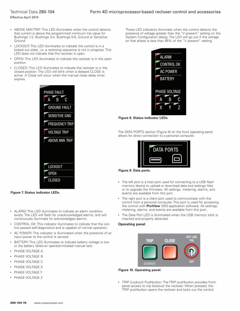
• ABOVE MIN TRIP: This LED illuminates when the control detects that current is above the programmed minimum trip value for Bushings 1-2, Bushings 3-4, Bushings 5-6, Ground or Sensitive Ground.
• LOCKOUT: This LED illuminates to indicate the control is in a locked out state, i.e. a reclosing sequence is not in progress. This LED does not indicate that the recloser is open.
• OPEN: This LED illuminates to indicate the recloser is in the open position.
• CLOSED: This LED illuminates to indicate the recloser is in the closed position. The LED will blink when a delayed CLOSE is active. A Close will occur when the manual close delay timer expires.
• ALARM: This LED illuminates to indicate an alarm condition exists. The LED will flash for unacknowledged alarms, and will continuously illuminate for acknowledged alarms.
• CONTROL OK: This indicator illuminates to indicate that the con-trol passed self-diagnostics and is capable of normal operation.
• AC POWER: This indicator is illuminated when the presence of ac input power to the control is sensed.
• BATTERY: This LED illuminates to indicate battery voltage is low or the battery failed an operator-initiated manual test.
• PHASE VOLTAGE A• PHASE VOLTAGE B• PHASE VOLTAGE C• PHASE VOLTAGE X• PHASE VOLTAGE Y• PHASE VOLTAGE Z
These LED indicators illuminate when the control detects the presence of voltage greater than the “V present” setting on the System Configuration dialog. The LED will go out if the voltage on that phase is less than 95% of the “V present” setting.
The DATA PORTS section (Figure 9) on the front operating panel allows for direct connection to a personal computer.
• The left port is a host port used for connecting to a USB flash memory device to upload or download data and settings files or to upgrade the firmware. All settings, metering, alarms, and events are available from this port.
• The right port is a client port used to communicate with the control from a personal computer. This port is used for accessing the control with ProView NXG application software. All settings, metering, alarms, and events are available from this port.
• The Data Port LED is illuminated when the USB memory stick is inserted and properly detected.
Operating panel
• TRIP (Lockout) Pushbutton: The TRIP pushbutton provides front-panel access to trip (lockout) the recloser. When pressed, the TRIP pushbutton opens the recloser and locks out the control.
DATA PORTS
ENTER
EDITESC
PHASE FAULT
A B C
GROUND FAULT
ABOVE MIN TRIP
LOCKOUT
OPEN
CLOSED
VOLTAGE TRIP
FREQUENCY TRIP
SENSITIVE GND
A B C
X Y Z
PHASE VOLTAGE
ALARM
BATTERY
AC POWER
CONTROL OK
ALTPROFILE 1
GND TRIPBLOCKED
NONRECLOSE
SUPER-VISORY
OFF
HOT LINETAGTRIP
OFF(LOCKOUT)
CLOSE
Figure 7. Status indicator LEDs.
DATA PORTS
ENTER
EDITESC
PHASE FAULT
A B C
GROUND FAULT
ABOVE MIN TRIP
LOCKOUT
OPEN
CLOSED
VOLTAGE TRIP
FREQUENCY TRIP
SENSITIVE GND
A B C
X Y Z
PHASE VOLTAGE
ALARM
BATTERY
AC POWER
CONTROL OK
ALTPROFILE 1
GND TRIPBLOCKED
NONRECLOSE
SUPER-VISORY
OFF
HOT LINETAGTRIP
OFF(LOCKOUT)
CLOSE
Figure 8. Status indicator LEDs.
DATA PORTS
ENTER
EDITESC
PHASE FAULT
A B C
GROUND FAULT
ABOVE MIN TRIP
LOCKOUT
OPEN
CLOSED
VOLTAGE TRIP
FREQUENCY TRIP
SENSITIVE GND
A B C
X Y Z
PHASE VOLTAGE
ALARM
BATTERY
AC POWER
CONTROL OK
ALTPROFILE 1
GND TRIPBLOCKED
NONRECLOSE
SUPER-VISORY
OFF
HOT LINETAGTRIP
OFF(LOCKOUT)
CLOSE
Figure 9. Data ports.
DATA PORTS
ENTER
EDITESC
PHASE FAULT
A B C
GROUND FAULT
ABOVE MIN TRIP
LOCKOUT
OPEN
CLOSED
VOLTAGE TRIP
FREQUENCY TRIP
SENSITIVE GND
A B C
X Y Z
PHASE VOLTAGE
ALARM
BATTERY
AC POWER
CONTROL OK
ALTPROFILE 1
GND TRIPBLOCKED
NONRECLOSE
SUPER-VISORY
OFF
HOT LINETAGTRIP
OFF(LOCKOUT)
CLOSE
Figure 10. Operating panel.
280-104-10
Technical Data 280-104Effective April 2014
Form 4D microprocessor-based recloser control and accessories
www.cooperpower.com
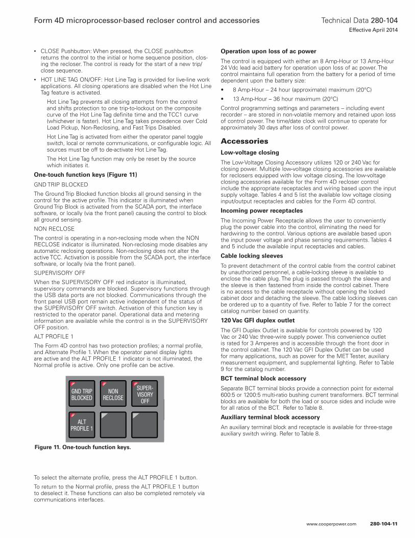
• CLOSE Pushbutton: When pressed, the CLOSE pushbutton returns the control to the initial or home sequence position, clos-ing the recloser. The control is ready for the start of a new trip/close sequence.
• HOT LINE TAG ON/OFF: Hot Line Tag is provided for live-line work applications. All closing operations are disabled when the Hot Line Tag feature is activated.
Hot Line Tag prevents all closing attempts from the control and shifts protection to one trip-to-lockout on the composite curve of the Hot Line Tag definite time and the TCC1 curve (whichever is faster). Hot Line Tag takes precedence over Cold Load Pickup, Non-Reclosing, and Fast Trips Disabled.
Hot Line Tag is activated from either the operator panel toggle switch, local or remote communications, or configurable logic. All sources must be off to de-activate Hot Line Tag.
The Hot Line Tag function may only be reset by the source which initiates it.
One-touch function keys (Figure 11)
GND TRIP BLOCKED
The Ground Trip Blocked function blocks all ground sensing in the control for the active profile. This indicator is illuminated when Ground Trip Block is activated from the SCADA port, the interface software, or locally (via the front panel) causing the control to block all ground sensing.
NON RECLOSE
The control is operating in a non-reclosing mode when the NON RECLOSE indicator is illuminated. Non-reclosing mode disables any automatic reclosing operations. Non-reclosing does not alter the active TCC. Activation is possible from the SCADA port, the interface software, or locally (via the front panel).
SUPERVISORY OFF
When the SUPERVISORY OFF red indicator is illuminated, supervisory commands are blocked. Supervisory functions through the USB data ports are not blocked. Communications through the front panel USB port remain active independent of the status of the SUPERVISORY OFF switch. Activation of this function key is restricted to the operator panel. Operational data and metering information are available while the control is in the SUPERVISORY OFF position.
ALT PROFILE 1
The Form 4D control has two protection profiles; a normal profile, and Alternate Profile 1. When the operator panel display lights are active and the ALT PROFILE 1 indicator is not illuminated, the Normal profile is active. Only one profile can be active.
To select the alternate profile, press the ALT PROFILE 1 button.
To return to the Normal profile, press the ALT PROFILE 1 button to deselect it. These functions can also be completed remotely via communications interfaces.
Operation upon loss of ac power
The control is equipped with either an 8 Amp-Hour or 13 Amp-Hour 24 Vdc lead acid battery for operation upon loss of ac power. The control maintains full operation from the battery for a period of time dependent upon the battery size:
• 8 Amp-Hour – 24 hour (approximate) maximum (20°C)
• 13 Amp-Hour – 36 hour maximum (20°C)
Control programming settings and parameters – including event recorder – are stored in non-volatile memory and retained upon loss of control power. The time/date clock will continue to operate for approximately 30 days after loss of control power.
AccessoriesLow-voltage closing
The Low-Voltage Closing Accessory utilizes 120 or 240 Vac for closing power. Multiple low-voltage closing accessories are available for reclosers equipped with low voltage closing. The low-voltage closing accessories available for the Form 4D recloser control include the appropriate receptacles and wiring based upon the input supply voltage. Tables 4 and 5 list the available low voltage closing input/output receptacles and cables for the Form 4D control.
Incoming power receptacles
The Incoming Power Receptacle allows the user to conveniently plug the power cable into the control, eliminating the need for hardwiring to the control. Various options are available based upon the input power voltage and phase sensing requirements. Tables 4 and 5 include the available input receptacles and cables.
Cable locking sleeves
To prevent detachment of the control cable from the control cabinet by unauthorized personnel, a cable-locking sleeve is available to enclose the cable plug. The plug is passed through the sleeve and the sleeve is then fastened from inside the control cabinet. There is no access to the cable receptacle without opening the locked cabinet door and detaching the sleeve. The cable locking sleeves can be ordered up to a quantity of five. Refer to Table 7 for the correct catalog number based on quantity.
120 Vac GFI duplex outlet
The GFI Duplex Outlet is available for controls powered by 120 Vac or 240 Vac three-wire supply power. This convenience outlet is rated for 3 Amperes and is accessible through the front door in the control cabinet. The 120 Vac GFI Duplex Outlet can be used for many applications, such as power for the MET Tester, auxiliary measurement equipment, and supplemental lighting. Refer to Table 9 for the catalog number.
BCT terminal block accessory
Separate BCT terminal blocks provide a connection point for external 600:5 or 1200:5 multi-ratio bushing current transformers. BCT terminal blocks are available for both the load or source sides and include wire for all ratios of the BCT. Refer to Table 8.
Auxiliary terminal block accessory
An auxiliary terminal block and receptacle is available for three-stage auxiliary switch wiring. Refer to Table 8.
DATA PORTS
ENTER
EDITESC
PHASE FAULT
A B C
GROUND FAULT
ABOVE MIN TRIP
LOCKOUT
OPEN
CLOSED
VOLTAGE TRIP
FREQUENCY TRIP
SENSITIVE GND
A B C
X Y Z
PHASE VOLTAGE
ALARM
BATTERY
AC POWER
CONTROL OK
ALTPROFILE 1
GND TRIPBLOCKED
NONRECLOSE
SUPER-VISORY
OFF
HOT LINETAGTRIP
OFF(LOCKOUT)
CLOSE
Figure 11. One-touch function keys.
280-104-11
Technical Data 280-104Effective April 2014
Form 4D microprocessor-based recloser control and accessories
www.cooperpower.com
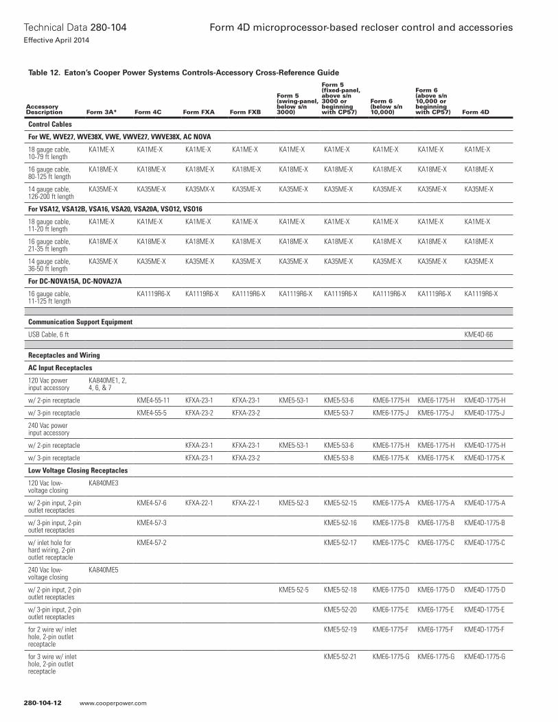
Table 12. Eaton’s Cooper Power Systems Controls-Accessory Cross-Reference Guide
Accessory Description Form 3A* Form 4C Form FXA Form FXB
Form 5 (swing-panel, below s/n 3000)
Form 5 (fixed-panel, above s/n 3000 or beginning with CP57)
Form 6 (below s/n 10,000)
Form 6 (above s/n 10,000 or beginning with CP57) Form 4D
Control Cables
For WE, WVE27, WVE38X, VWE, VWVE27, VWVE38X, AC NOVA
18 gauge cable, 10-79 ft length
KA1ME-X KA1ME-X KA1ME-X KA1ME-X KA1ME-X KA1ME-X KA1ME-X KA1ME-X KA1ME-X
16 gauge cable, 80-125 ft length
KA18ME-X KA18ME-X KA18ME-X KA18ME-X KA18ME-X KA18ME-X KA18ME-X KA18ME-X KA18ME-X
14 gauge cable, 126-200 ft length
KA35ME-X KA35ME-X KA35MX-X KA35ME-X KA35ME-X KA35ME-X KA35ME-X KA35ME-X KA35ME-X
For VSA12, VSA12B, VSA16, VSA20, VSA20A, VSO12, VSO16
18 gauge cable, 11-20 ft length
KA1ME-X KA1ME-X KA1ME-X KA1ME-X KA1ME-X KA1ME-X KA1ME-X KA1ME-X KA1ME-X
16 gauge cable, 21-35 ft length
KA18ME-X KA18ME-X KA18ME-X KA18ME-X KA18ME-X KA18ME-X KA18ME-X KA18ME-X KA18ME-X
14 gauge cable, 36-50 ft length
KA35ME-X KA35ME-X KA35ME-X KA35ME-X KA35ME-X KA35ME-X KA35ME-X KA35ME-X KA35ME-X
For DC-NOVA15A, DC-NOVA27A
16 gauge cable, 11-125 ft length
KA1119R6-X KA1119R6-X KA1119R6-X KA1119R6-X KA1119R6-X KA1119R6-X KA1119R6-X KA1119R6-X
Communication Support Equipment
USB Cable, 6 ft KME4D-66
Receptacles and Wiring
AC Input Receptacles
120 Vac power input accessory
KA840ME1, 2, 4, 6, & 7
w/ 2-pin receptacle KME4-55-11 KFXA-23-1 KFXA-23-1 KME5-53-1 KME5-53-6 KME6-1775-H KME6-1775-H KME4D-1775-H
w/ 3-pin receptacle KME4-55-5 KFXA-23-2 KFXA-23-2 KME5-53-7 KME6-1775-J KME6-1775-J KME4D-1775-J
240 Vac power input accessory
w/ 2-pin receptacle KFXA-23-1 KFXA-23-1 KME5-53-1 KME5-53-6 KME6-1775-H KME6-1775-H KME4D-1775-H
w/ 3-pin receptacle KFXA-23-1 KFXA-23-2 KME5-53-8 KME6-1775-K KME6-1775-K KME4D-1775-K
Low Voltage Closing Receptacles
120 Vac low-voltage closing
KA840ME3
w/ 2-pin input, 2-pin outlet receptacles
KME4-57-6 KFXA-22-1 KFXA-22-1 KME5-52-3 KME5-52-15 KME6-1775-A KME6-1775-A KME4D-1775-A
w/ 3-pin input, 2-pin outlet receptacles
KME4-57-3 KME5-52-16 KME6-1775-B KME6-1775-B KME4D-1775-B
w/ inlet hole for hard wiring, 2-pin outlet receptacle
KME4-57-2 KME5-52-17 KME6-1775-C KME6-1775-C KME4D-1775-C
240 Vac low-voltage closing
KA840ME5
w/ 2-pin input, 2-pin outlet receptacles
KME5-52-5 KME5-52-18 KME6-1775-D KME6-1775-D KME4D-1775-D
w/ 3-pin input, 2-pin outlet receptacles
KME5-52-20 KME6-1775-E KME6-1775-E KME4D-1775-E
for 2 wire w/ inlet hole, 2-pin outlet receptacle
KME5-52-19 KME6-1775-F KME6-1775-F KME4D-1775-F
for 3 wire w/ inlet hole, 2-pin outlet receptacle
KME5-52-21 KME6-1775-G KME6-1775-G KME4D-1775-G
280-104-12
Technical Data 280-104Effective April 2014
Form 4D microprocessor-based recloser control and accessories
www.cooperpower.com
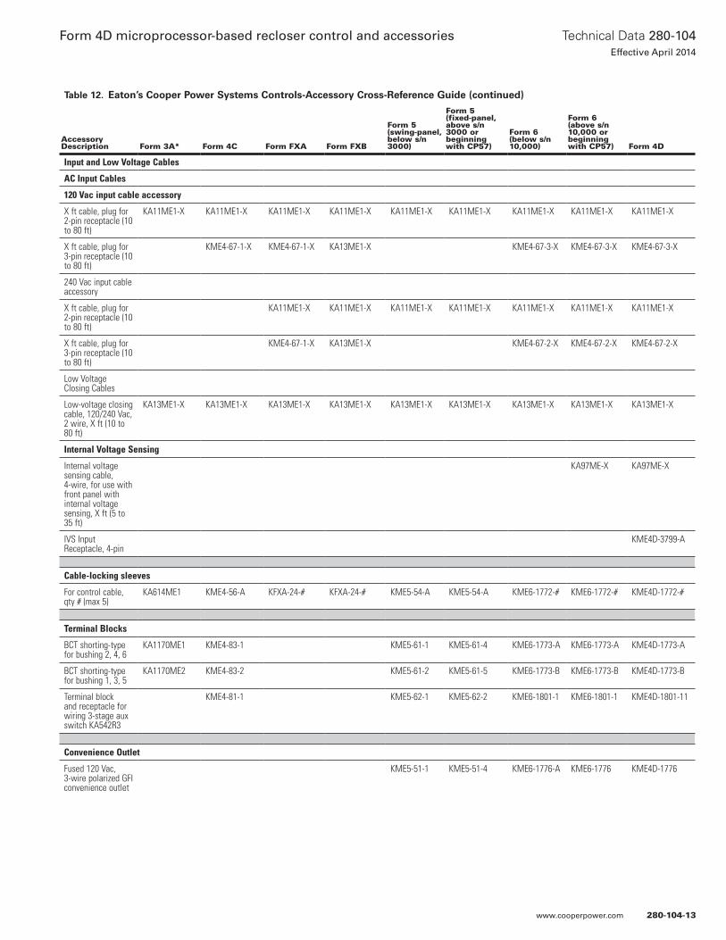
Table 12. Eaton’s Cooper Power Systems Controls-Accessory Cross-Reference Guide (continued)
Accessory Description Form 3A* Form 4C Form FXA Form FXB
Form 5 (swing-panel, below s/n 3000)
Form 5 (fixed-panel, above s/n 3000 or beginning with CP57)
Form 6 (below s/n 10,000)
Form 6 (above s/n 10,000 or beginning with CP57) Form 4D
Input and Low Voltage Cables
AC Input Cables
120 Vac input cable accessory
X ft cable, plug for 2-pin receptacle (10 to 80 ft)
KA11ME1-X KA11ME1-X KA11ME1-X KA11ME1-X KA11ME1-X KA11ME1-X KA11ME1-X KA11ME1-X KA11ME1-X
X ft cable, plug for 3-pin receptacle (10 to 80 ft)
KME4-67-1-X KME4-67-1-X KA13ME1-X KME4-67-3-X KME4-67-3-X KME4-67-3-X
240 Vac input cable accessory
X ft cable, plug for 2-pin receptacle (10 to 80 ft)
KA11ME1-X KA11ME1-X KA11ME1-X KA11ME1-X KA11ME1-X KA11ME1-X KA11ME1-X
X ft cable, plug for 3-pin receptacle (10 to 80 ft)
KME4-67-1-X KA13ME1-X KME4-67-2-X KME4-67-2-X KME4-67-2-X
Low Voltage Closing Cables
Low-voltage closing cable, 120/240 Vac, 2 wire, X ft (10 to 80 ft)
KA13ME1-X KA13ME1-X KA13ME1-X KA13ME1-X KA13ME1-X KA13ME1-X KA13ME1-X KA13ME1-X KA13ME1-X
Internal Voltage Sensing
Internal voltage sensing cable, 4-wire, for use with front panel with internal voltage sensing, X ft (5 to 35 ft)
KA97ME-X KA97ME-X
IVS Input Receptacle, 4-pin
KME4D-3799-A
Cable-locking sleeves
For control cable, qty # (max 5)
KA614ME1 KME4-56-A KFXA-24-# KFXA-24-# KME5-54-A KME5-54-A KME6-1772-# KME6-1772-# KME4D-1772-#
Terminal Blocks
BCT shorting-type for bushing 2, 4, 6
KA1170ME1 KME4-83-1 KME5-61-1 KME5-61-4 KME6-1773-A KME6-1773-A KME4D-1773-A
BCT shorting-type for bushing 1, 3, 5
KA1170ME2 KME4-83-2 KME5-61-2 KME5-61-5 KME6-1773-B KME6-1773-B KME4D-1773-B
Terminal block and receptacle for wiring 3-stage aux switch KA542R3
KME4-81-1 KME5-62-1 KME5-62-2 KME6-1801-1 KME6-1801-1 KME4D-1801-11
Convenience Outlet
Fused 120 Vac, 3-wire polarized GFI convenience outlet
KME5-51-1 KME5-51-4 KME6-1776-A KME6-1776 KME4D-1776
280-104-13
Technical Data 280-104Effective April 2014
Form 4D microprocessor-based recloser control and accessories
www.cooperpower.com
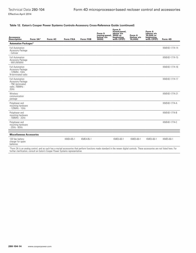
Table 12. Eaton’s Cooper Power Systems Controls-Accessory Cross-Reference Guide (continued)
Accessory Description Form 3A* Form 4C Form FXA Form FXB
Form 5 (swing-panel, below s/n 3000)
Form 5 (fixed-panel, above s/n 3000 or beginning with CP57)
Form 6 (below s/n 10,000)
Form 6 (above s/n 10,000 or beginning with CP57) Form 4D
Automation Packages*
Full Automation Accessory Package - Cellular
KME4D-1774-14
Full Automation Accessory Package - WiFi/WiMAX
KME4D-1774-15
Full Automation Accessory Package - 125MHz -1GHz N-terminated radio
KME4D-1774-16
Full Automation Accessory Package - TNC-terminated radio, 700MHz - 2GHz
KME4D-1774-17
Wireless communication package
KME4D-1774-21
Polyphaser and mounting hardware - 125MHz - 1GHz
KME4D-1774-A
Polyphaser and mounting hardware - 700MHz - 2GHz
KME4D-1774-B
Polyphaser and mounting hardware - 2GHz - 6GHz
KME4D-1774-C
Miscellaneous Accessories
120 Vac battery charger for spare batteries
KME4-85-1 KME4-85-1 KME5-60-1 KME5-60-1 KME5-60-1 KME5-60-1
*Form 3A is an analog control, and as such has a myriad accessories that perform functions made standard in the newer digital controls. These accessories are not listed here. For further clarification, consult an Eaton’s Cooper Power Systems representative.
280-104-14
Technical Data 280-104Effective April 2014
Form 4D microprocessor-based recloser control and accessories
www.cooperpower.com

280-104-15
Technical Data 280-104Effective April 2014
Form 4D microprocessor-based recloser control and accessories
www.cooperpower.com
Eaton, Cooper Power Systems, NOVA, and ProView NXG are valuable trademarks of Eaton in the U.S. and other countries. You are not permitted to use the these trademarks without the prior written consent of Eaton.IEEE Std C57.12.28™-2005 and Std C57.12.29™-2005 standards are trademarks of the Institute of Electrical and Electronics Engineers, Inc., (IEEE). This publication is not endorsed or approved by the IEEE.IEEE® is a registered trademark of the Institute of Electrical and Electronics Engineers, Inc.ANSI® is a registered trademark of American National Standards Institute.
Form 4D microprocessor-based recloser control and accessories
Eaton1000 Eaton BoulevardCleveland, OH 44122United StatesEaton.com
Eaton’s Cooper Power Systems Business2300 Badger DriveWaukesha, WI 53188United StatesCooperpower.com
© 2014 EatonAll Rights ReservedPrinted in USAPublication No. 280-104April 2014
Technical Data 280-104Effective April 2014
For Eaton’s Cooper Power Systems Form 4D recloser product information call 1-877-277-4636 or visit: www.cooperpower.com.
280-104-16
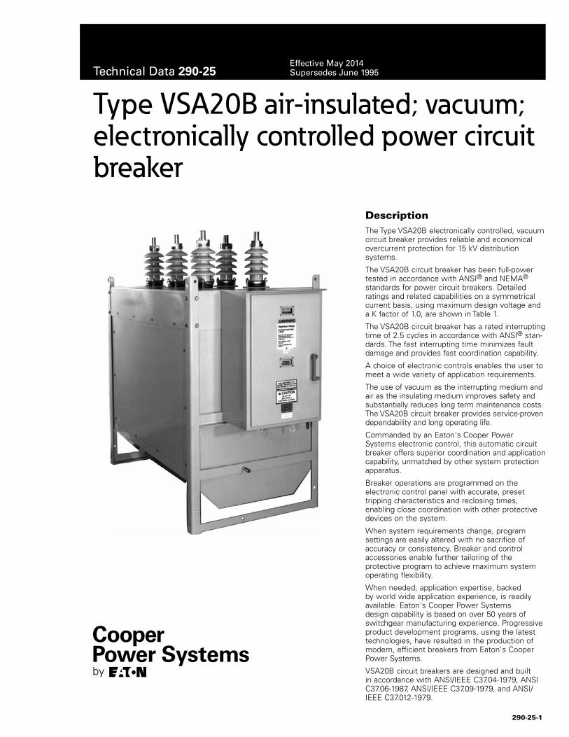
DescriptionThe Type VSA20B electronically controlled, vacuum circuit breaker provides reliable and economical overcurrent protection for 15 kV distribution systems.
The VSA20B circuit breaker has been full-power tested in accordance with ANSI® and NEMA® standards for power circuit breakers. Detailed ratings and related capabilities on a symmetrical current basis, using maximum design voltage and a K factor of 1.0, are shown in Table 1.
The VSA20B circuit breaker has a rated interrupting time of 2.5 cycles in accordance with ANSI® stan-dards. The fast interrupting time minimizes fault damage and provides fast coordination capability.
A choice of electronic controls enables the user to meet a wide variety of application requirements.
The use of vacuum as the interrupting medium and air as the insulating medium improves safety and substantially reduces long term maintenance costs. The VSA20B circuit breaker provides service-proven dependability and long operating life.
Commanded by an Eaton's Cooper Power Systems electronic control, this automatic circuit breaker offers superior coordination and application capability, unmatched by other system protection apparatus.
Breaker operations are programmed on the electronic control panel with accurate, preset tripping characteristics and reclosing times, enabling close coordination with other protective devices on the system.
When system requirements change, program settings are easily altered with no sacrifice of accuracy or consistency. Breaker and control accessories enable further tailoring of the protective program to achieve maximum system operating flexibility.
When needed, application expertise, backed by world wide application experience, is readily available. Eaton's Cooper Power Systems design capability is based on over 50 years of switchgear manufacturing experience. Progressive product development programs, using the latest technologies, have resulted in the production of modern, efficient breakers from Eaton's Cooper Power Systems.
VSA20B circuit breakers are designed and built in accordance with ANSI/IEEE C37.04-1979, ANSI C37.06-1987, ANSI/IEEE C37.09-1979, and ANSI/IEEE C37.012-1979.
Type VSA20B air-insulated; vacuum; electronically controlled power circuit breaker
290-25-1
Technical Data 290-25Effective May 2014Supersedes June 1995
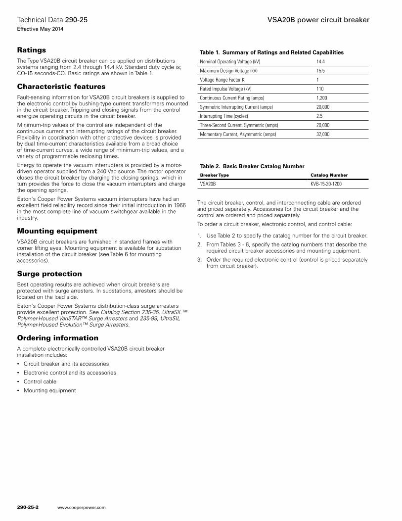
RatingsThe Type VSA20B circuit breaker can be applied on distributions systems ranging from 2.4 through 14.4 kV. Standard duty cycle is; CO-15 seconds-CO. Basic ratings are shown in Table 1.
Characteristic featuresFault-sensing information for VSA20B circuit breakers is supplied to the electronic control by bushing-type current transformers mounted in the circuit breaker. Tripping and closing signals from the control energize operating circuits in the circuit breaker.
Minimum-trip values of the control are independent of the continuous current and interrupting ratings of the circuit breaker. Flexibility in coordination with other protective devices is provided by dual time-current characteristics available from a broad choice of time-current curves, a wide range of minimum-trip values, and a variety of programmable reclosing times.
Energy to operate the vacuum interrupters is provided by a motor-driven operator supplied from a 240 Vac source. The motor operator closes the circuit breaker by charging the closing springs, which in turn provides the force to close the vacuum interrupters and charge the opening springs.
Eaton's Cooper Power Systems vacuum interrupters have had an excellent field reliability record since their initial introduction in 1966 in the most complete line of vacuum switchgear available in the industry.
Mounting equipmentVSA20B circuit breakers are furnished in standard frames with corner lifting eyes. Mounting equipment is available for substation installation of the circuit breaker (see Table 6 for mounting accessories).
Surge protection Best operating results are achieved when circuit breakers are protected with surge arresters. In substations, arresters should be located on the load side.
Eaton's Cooper Power Systems distribution-class surge arresters provide excellent protection. See Catalog Section 235-35, UltraSIL™ Polymer-Housed VariSTAR™ Surge Arresters and 235-99, UltraSIL Polymer-Housed Evolution™ Surge Arresters.
Ordering informationA complete electronically controlled VSA20B circuit breaker installation includes:• Circuit breaker and its accessories• Electronic control and its accessories• Control cable• Mounting equipment
The circuit breaker, control, and interconnecting cable are ordered and priced separately. Accessories for the circuit breaker and the control are ordered and priced separately.
To order a circuit breaker, electronic control, and control cable:
1. Use Table 2 to specify the catalog number for the circuit breaker.
2. From Tables 3 - 6, specify the catalog numbers that describe the required circuit breaker accessories and mounting equipment.
3. Order the required electronic control (control is priced separately from circuit breaker).
Table 2. Basic Breaker Catalog Number
Breaker Type Catalog Number
VSA20B KVB-15-20-1200
Table 1. Summary of Ratings and Related Capabilities
Nominal Operating Voltage (kV) 14.4
Maximum Design Voltage (kV) 15.5
Voltage Range Factor K 1
Rated Impulse Voltage (kV) 110
Continuous Current Rating (amps) 1,200
Symmetric Interrupting Current (amps) 20,000
Interrupting Time (cycles) 2.5
Three-Second Current, Symmetric (amps) 20,000
Momentary Current, Asymmetric (amps) 32,000
290-25-2
Technical Data 290-25Effective May 2014
VSA20B power circuit breaker
www.cooperpower.com
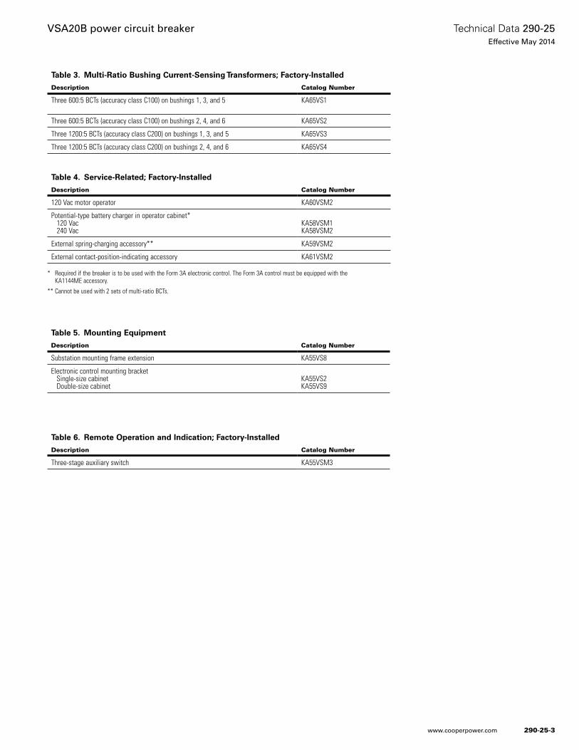
Table 3. Multi-Ratio Bushing Current-Sensing Transformers; Factory-Installed
Description Catalog Number
Three 600:5 BCTs (accuracy class C100) on bushings 1, 3, and 5 KA65VS1
Three 600:5 BCTs (accuracy class C100) on bushings 2, 4, and 6 KA65VS2
Three 1200:5 BCTs (accuracy class C200) on bushings 1, 3, and 5 KA65VS3
Three 1200:5 BCTs (accuracy class C200) on bushings 2, 4, and 6 KA65VS4
* Required if the breaker is to be used with the Form 3A electronic control. The Form 3A control must be equipped with the KA1144ME accessory.
** Cannot be used with 2 sets of multi-ratio BCTs.
Table 6. Remote Operation and Indication; Factory-Installed
Description Catalog Number
Three-stage auxiliary switch KA55VSM3
Table 5. Mounting Equipment
Description Catalog Number
Substation mounting frame extension KA55VS8
Electronic control mounting bracket Single-size cabinet Double-size cabinet
KA55VS2KA55VS9
Table 4. Service-Related; Factory-Installed
Description Catalog Number
120 Vac motor operator KA60VSM2
Potential-type battery charger in operator cabinet* 120 Vac 240 Vac
KA58VSM1KA58VSM2
External spring-charging accessory** KA59VSM2
External contact-position-indicating accessory KA61VSM2
290-25-3
Technical Data 290-25Effective May 2014
VSA20B power circuit breaker
www.cooperpower.com
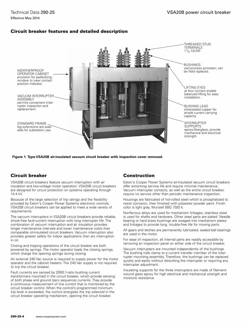
Circuit breakerVSA20B circuit breakers feature vacuum interruption with air insulation and low-voltage motor operation. VSA20B circuit breakers are designed for circuit protection on systems operating through 14.4 kV.
Because of the large selection of trip ratings and the flexibility provided by Eaton's Cooper Power Systems electronic controls, VSA20B circuit breakers can be applied to meet a wide variety of requirements.
The vacuum interrupters in VSA20B circuit breakers provide reliable, shock-free fault-current interruption with long interrupter life. The combination of vacuum interruption and air insulation provides longer maintenance intervals and lower maintenance costs than comparable oil-insulated circuit breakers. Vacuum interruption also provides greater safety for indoor applications than arc interruption in oil.
Closing and tripping operations of the circuit breaker are both powered by springs. The motor operator loads the closing springs, which charge the opening springs during closing.
An external 240 Vac source is required to supply power for the motor operator and the cabinet heaters. The 240 Vac supply is not required to trip the circuit breaker.
Fault currents are sensed by 2000:1-ratio bushing current transformers mounted in the circuit breaker, which provide sensing of both phase and ground (zero sequence) currents. They provide a continuous measurement of line current that is monitored by the circuit breaker control. When the control’s programmed minimum trip level is exceeded, the control energizes the trip solenoid in the circuit breaker operating mechanism, opening the circuit breaker.
ConstructionEaton's Cooper Power Systems air-insulated vacuum circuit breakers offer extra-long service life and require minimal maintenance. Vacuum interrupter contacts, as well as the entire circuit breaker, require no service other than periodic maintenance inspection.
Housings are fabricated of hot-rolled steel which is phosphatized to resist corrosion, then finished with polyester powder paint. Finish color is light gray, Munsell 5BG 7.0/0.4.
Nonferrous alloys are used for mechanism linkages; stainless steel is used for shafts and hardware. Other steel parts are plated. Needle bearing or hard brass bushings are swaged into mechanism plates and linkages to provide long, trouble-free life for moving parts.
All gears and latches are permanently lubricated; sealed ball bearings are used in the motor.
For ease of inspection, all internal parts are readily accessible by removing an inspection panel on either side of the circuit breaker.
Vacuum interrupters are mounted independently of the bushings. The bushing rods clamp to a current transfer member of the inter-rupter mounting assembly. Therefore, the bushings can be replaced quickly and easily without disturbing the interrupter or requiring any interrupter adjustment.
Insulating supports for the three interrupters are made of filament-wound glass epoxy for high electrical and mechanical strength and moisture resistance.
Figure 1. Type VSA20B air-insulated vacuum circuit breaker with inspection cover removed.
Circuit breaker features and detailed description
WEATHERPROOF OPERATOR CABINET provision for padlocking; window to view contact position indicator.
VACUUM INTERRUPTER ASSEMBLY permits convenient inter-rupter inspection and replacement.
STANDARD FRAME leg extensions are avail-able for substation use.
BUSHINGS wet-process porcelain; can be field replaced.
LIFTING EYES at four corners enable balanced lifting for easy installation.
BUSHING LEAD silverplated copper for ample current carrying capacity.
INTERRUPTER SUPPORTSepoxy-fiberglass; provide mechanical and electrical strength.
THREADED STUD TERMINALS 11/4-12UNF
290-25-4
Technical Data 290-25Effective May 2014
VSA20B power circuit breaker
www.cooperpower.com

Cabinet heaters are provided in both the operator mechanism cabinet and the interrupter mechanism cabinet. The heaters are supplied from the 240-Vac auxiliary power source and are connected through a DPST on-off toggle switch and one amp fuses. The mechanism cabinet heater operates at 57 watts. The enclosure heaters operate at 115 watts total.
Motor operation
VSA20B air-insulated, vacuum circuit breakers employ a 240 Vac, motor-driven operating mechanism to charge closing and opening springs.
Tripping
Circuit breaker tripping employs stored spring energy. When line cur-rent exceeds the programmed minimum-trip value, in one or more phases, the control energizes a trip solenoid in the operating mecha-nism. The solenoid trips a latch which releases a spring-loaded toggle assembly, opening the circuit breaker contacts and a switch which interrupts the 24-volt signal from the control. Maximum clearing time is 2 1¼2 cycles.
Tripping, because it employs stored spring energy released by a 24-volt signal from the control, will occur even if the 240-volt supply is lost.
Closing
Closing energy, as well as the force to charge the opening springs, is supplied by the motor operating mechanism, through motor-loaded closing springs. A 240 Vac motor charges the closing springs through a multi-stage gear drive. When 240 Vac is present, the motor is auto-matically operated to keep the closing springs in a charged state.
To close the circuit breaker, the control initiates a signal which ener-gizes a solenoid in the circuit breaker operating mechanism. Once actuated, the solenoid releases the closing springs, which close the vacuum interrupters and charge the opening springs.
Stored energy provides multiple operationsShould the circuit breaker lose 240 Vac motor supply voltage while the closing spring is charged and contacts are closed, an Open-Close-Open sequence remains stored in the circuit breaker operating mechanism. If the circuit breaker trips under these conditions, the stored closing operation allows an immediate reclosing, if required. After such a closing, one additional trip operation then remains stored. Once closed, the circuit breaker always contains energy for at least one trip operation.
Figure 2. VSA20B circuit breaker operating mechanism components.
Figure 3. Vacuum interrupter assembly.
CONTACT POSITION INDICATOR linked to main operating shaft; visible through window in operator cabinet.
DRIVE MOTOR 240 Vac operates closing mechanism; needs no lubrication.
SPRING CHARGE INDICATOR linked to closing springs; for indication of stored energy operation in event of loss of low voltage motor supply.
MANUAL CLOSE LEVERpermits manual closing of the circuit breaker.
AUXILIARY SWITCH (accessory) is available to provide remote indication of circuit breaker contact position.
MANUAL RESET-TRIP KNOBprovides means for manual tripping; must be in RESET position to permit closing.
OPERATOR CABINET HEATERcontrol switch and fuse.
MULTI-RATIO CTTERMINAL BOARD(accessory) provides convenient customer connection to the desired current transformer ratio.
MANUAL TRIP PULLRINGprovides means for manual tripping.
MANUAL CLOSEPULLRINGpermits manual closing of the circuit breaker.
290-25-5
Technical Data 290-25Effective May 2014
VSA20B power circuit breaker
www.cooperpower.com
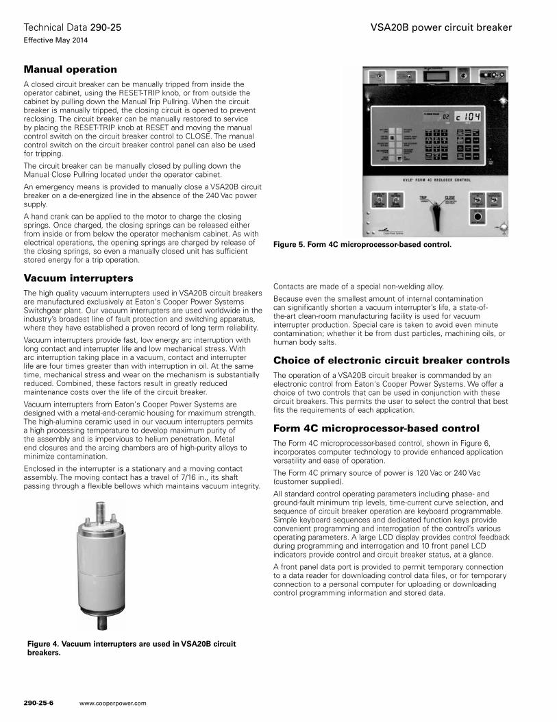
Manual operationA closed circuit breaker can be manually tripped from inside the operator cabinet, using the RESET-TRIP knob, or from outside the cabinet by pulling down the Manual Trip Pullring. When the circuit breaker is manually tripped, the closing circuit is opened to prevent reclosing. The circuit breaker can be manually restored to service by placing the RESET-TRIP knob at RESET and moving the manual control switch on the circuit breaker control to CLOSE. The manual control switch on the circuit breaker control panel can also be used for tripping.
The circuit breaker can be manually closed by pulling down the Manual Close Pullring located under the operator cabinet.
An emergency means is provided to manually close a VSA20B circuit breaker on a de-energized line in the absence of the 240 Vac power supply.
A hand crank can be applied to the motor to charge the closing springs. Once charged, the closing springs can be released either from inside or from below the operator mechanism cabinet. As with electrical operations, the opening springs are charged by release of the closing springs, so even a manually closed unit has sufficient stored energy for a trip operation.
Vacuum interruptersThe high quality vacuum interrupters used in VSA20B circuit breakers are manufactured exclusively at Eaton's Cooper Power Systems Switchgear plant. Our vacuum interrupters are used worldwide in the industry’s broadest line of fault protection and switching apparatus, where they have established a proven record of long term reliability.
Vacuum interrupters provide fast, low energy arc interruption with long contact and interrupter life and low mechanical stress. With arc interruption taking place in a vacuum, contact and interrupter life are four times greater than with interruption in oil. At the same time, mechanical stress and wear on the mechanism is substantially reduced. Combined, these factors result in greatly reduced maintenance costs over the life of the circuit breaker.
Vacuum interrupters from Eaton's Cooper Power Systems are designed with a metal-and-ceramic housing for maximum strength. The high-alumina ceramic used in our vacuum interrupters permits a high processing temperature to develop maximum purity of the assembly and is impervious to helium penetration. Metal end closures and the arcing chambers are of high-purity alloys to minimize contamination.
Enclosed in the interrupter is a stationary and a moving contact assembly. The moving contact has a travel of 7/16 in., its shaft passing through a flexible bellows which maintains vacuum integrity.
Contacts are made of a special non-welding alloy.
Because even the smallest amount of internal contamination can significantly shorten a vacuum interrupter’s life, a state-of-the-art clean-room manufacturing facility is used for vacuum interrupter production. Special care is taken to avoid even minute contamination; whether it be from dust particles, machining oils, or human body salts.
Choice of electronic circuit breaker controlsThe operation of a VSA20B circuit breaker is commanded by an electronic control from Eaton's Cooper Power Systems. We offer a choice of two controls that can be used in conjunction with these circuit breakers. This permits the user to select the control that best fits the requirements of each application.
Form 4C microprocessor-based controlThe Form 4C microprocessor-based control, shown in Figure 6, incorporates computer technology to provide enhanced application versatility and ease of operation.
The Form 4C primary source of power is 120 Vac or 240 Vac (customer supplied).
All standard control operating parameters including phase- and ground-fault minimum trip levels, time-current curve selection, and sequence of circuit breaker operation are keyboard programmable. Simple keyboard sequences and dedicated function keys provide convenient programming and interrogation of the control’s various operating parameters. A large LCD display provides control feedback during programming and interrogation and 10 front panel LCD indicators provide control and circuit breaker status, at a glance.
A front panel data port is provided to permit temporary connection to a data reader for downloading control data files, or for temporary connection to a personal computer for uploading or downloading control programming information and stored data.
Figure 4. Vacuum interrupters are used in VSA20B circuit breakers.
Figure 5. Form 4C microprocessor-based control.
290-25-6
Technical Data 290-25Effective May 2014
VSA20B power circuit breaker
www.cooperpower.com
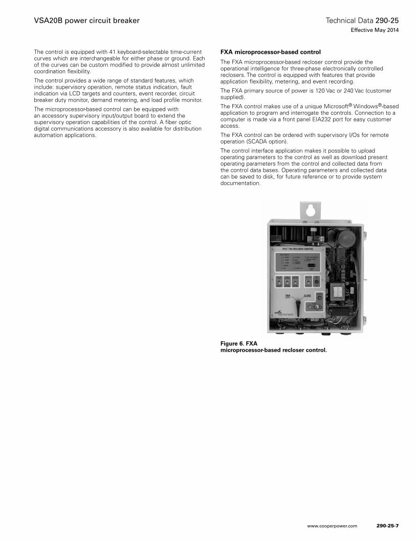
The control is equipped with 41 keyboard-selectable time-current curves which are interchangeable for either phase or ground. Each of the curves can be custom modified to provide almost unlimited coordination flexibility.
The control provides a wide range of standard features, which include: supervisory operation, remote status indication, fault indication via LCD targets and counters, event recorder, circuit breaker duty monitor, demand metering, and load profile monitor.
The microprocessor-based control can be equipped with an accessory supervisory input/output board to extend the supervisory operation capabilities of the control. A fiber optic digital communications accessory is also available for distribution automation applications.
FXA microprocessor-based control
The FXA microprocessor-based recloser control provide the operational intelligence for three-phase electronically controlled reclosers. The control is equipped with features that provide application flexibility, metering, and event recording.
The FXA primary source of power is 120 Vac or 240 Vac (customer supplied).
The FXA control makes use of a unique Microsoft® Windows®-based application to program and interrogate the controls. Connection to a computer is made via a front panel EIA232 port for easy customer access.
The FXA control can be ordered with supervisory I/Os for remote operation (SCADA option).
The control interface application makes it possible to upload operating parameters to the control as well as download present operating parameters from the control and collected data from the control data bases. Operating parameters and collected data can be saved to disk, for future reference or to provide system documentation.
Figure 6. FXA microprocessor-based recloser control.
290-25-7
Technical Data 290-25Effective May 2014
VSA20B power circuit breaker
www.cooperpower.com
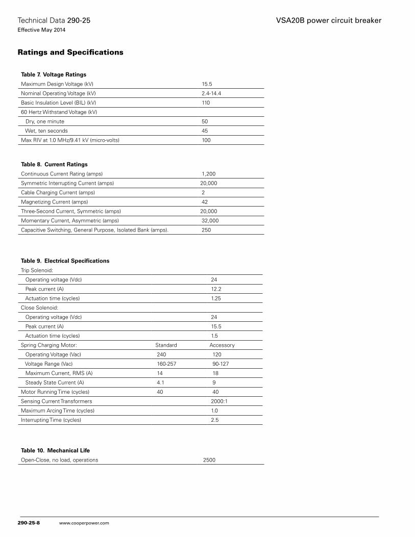
Table 7. Voltage Ratings
Maximum Design Voltage (kV) 15.5
Nominal Operating Voltage (kV) 2.4-14.4
Basic Insulation Level (BIL) (kV) 110
60 Hertz Withstand Voltage (kV)
Dry, one minute 50
Wet, ten seconds 45
Max RIV at 1.0 MHz/9.41 kV (micro-volts) 100
Table 8. Current Ratings
Continuous Current Rating (amps) 1,200
Symmetric Interrupting Current (amps) 20,000
Cable Charging Current (amps) 2
Magnetizing Current (amps) 42
Three-Second Current, Symmetric (amps) 20,000
Momentary Current, Asymmetric (amps) 32,000
Capacitive Switching, General Purpose, Isolated Bank (amps). 250
Table 9. Electrical Specifications
Trip Solenoid:
Operating voltage (Vdc) 24
Peak current (A) 12.2
Actuation time (cycles) 1.25
Close Solenoid:
Operating voltage (Vdc) 24
Peak current (A) 15.5
Actuation time (cycles) 1.5
Spring Charging Motor: Standard Accessory
Operating Voltage (Vac) 240 120
Voltage Range (Vac) 160-257 90-127
Maximum Current, RMS (A) 14 18
Steady State Current (A) 4.1 9
Motor Running Time (cycles) 40 40
Sensing Current Transformers 2000:1
Maximum Arcing Time (cycles) 1.0
Interrupting Time (cycles) 2.5
Ratings and Specifications
Table 10. Mechanical Life
Open-Close, no load, operations 2500
290-25-8
Technical Data 290-25Effective May 2014
VSA20B power circuit breaker
www.cooperpower.com
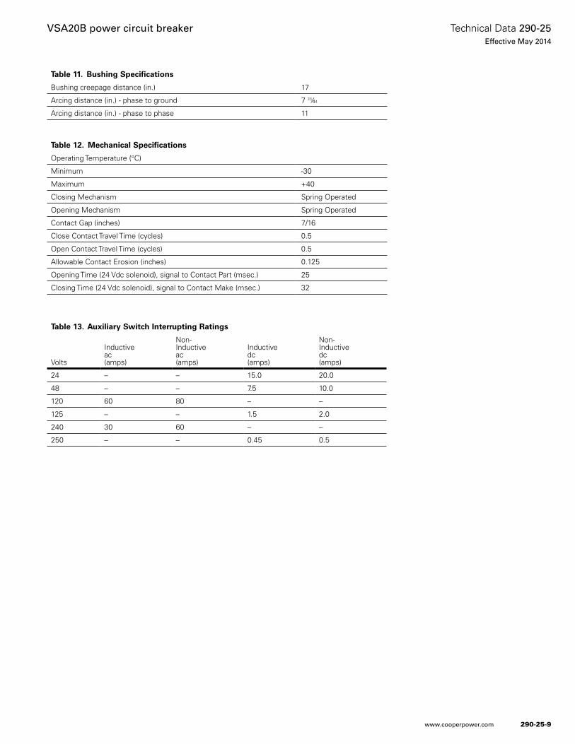
Table 12. Mechanical Specifications
Operating Temperature (°C)
Minimum -30
Maximum +40
Closing Mechanism Spring Operated
Opening Mechanism Spring Operated
Contact Gap (inches) 7/16
Close Contact Travel Time (cycles) 0.5
Open Contact Travel Time (cycles) 0.5
Allowable Contact Erosion (inches) 0.125
Opening Time (24 Vdc solenoid), signal to Contact Part (msec.) 25
Closing Time (24 Vdc solenoid), signal to Contact Make (msec.) 32
Table 13. Auxiliary Switch Interrupting Ratings
Volts
Inductiveac(amps)
Non-Inductiveac(amps)
Inductivedc(amps)
Non-Inductivedc(amps)
24 – – 15.0 20.0
48 – – 7.5 10.0
120 60 80 – –
125 – – 1.5 2.0
240 30 60 – –
250 – – 0.45 0.5
Table 11. Bushing Specifications
Bushing creepage distance (in.) 17
Arcing distance (in.) - phase to ground 7 3¼4
Arcing distance (in.) - phase to phase 11
290-25-9
Technical Data 290-25Effective May 2014
VSA20B power circuit breaker
www.cooperpower.com
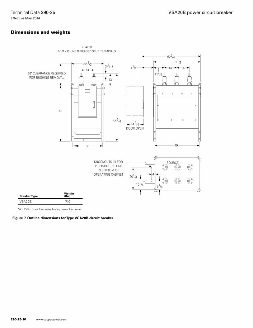
Figure 7. Outline dimensions for Type VSA20B circuit breaker.
26" CLEARANCE REQUIREDFOR BUSHING REMOVAL
50
62-3/4
13
3-7/1614
32-1/2
14 3/4DOOR OPEN
49
623/4511/2
1414
113/4
KNOCKOUTS (3) FOR1" CONDUIT FITTING
IN BOTTOM OFOPERATING CABINET
201/44
81/4101/4
30
VSA20B1-1/4 - 12 UNF THREADED STUD TERMINALS
111/4
SOURCE
Breaker TypeWeight (lbs)
VSA20B 740
*Add 25 lbs. for each accessory bushing current transformer.
Dimensions and weights
290-25-10
Technical Data 290-25Effective May 2014
VSA20B power circuit breaker
www.cooperpower.com
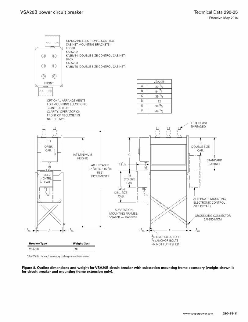
Figure 8. Outline dimensions and weight for VSA20B circuit breaker with substation mounting frame accessory (weight shown is for circuit breaker and mounting frame extension only).
ELEC.CNTRL.
CAB.
OPER.CAB.
A1 1/4 11/4
ADJUSTABLE97 7/8 TO 115 7/8
IN 3"INCREMENTS
343/4DBL. SIZE
CAB.
18STD. SIZE
CAB.
C
131/2
DDOUBLE-SIZE
CAB.
ESTANDARD
CABINET
1 1/4 1-1/4F
GROUNDING CONNECTOR2/0-250 MCM
3/4 DIA. HOLES FOR5/8 ANCHOR BOLTS(4), NOT FURNISHED
ALTERNATE MOUNTINGELECTRONIC CONTROL(SEE DETAIL)
OPTIONAL ARRANGEMENTSFOR MOUNTING ELECTRONIC CONTROL (FORCLARITY, OPERATOR ONFRONT OF RECLOSER ISNOT SHOWN)
STANDARD ELECTRONIC CONTROL CABINET MOUNTING BRACKETS:FRONTKA55VS2KA55VS4 (DOUBLE-SIZE CONTROL CABINET)BACKKA55VS3KA55VS5 (DOUBLE-SIZE CONTROL CABINET)
A
B
C
D
E
F
VSA20B
30 1/2
84 7/8
39 1/4
22
38 3/4
49 1/2
B(AT MINIMUM
HEIGHT)
FRONT
SUBSTATIONMOUNTING FRAMES:VSA20B — KA55VS8
1 1/4-12 UNFTHREADED
Breaker Type Weight (lbs)
VSA20B 890
*Add 25 lbs. for each accessory bushing current transformer.
290-25-11
Technical Data 290-25Effective May 2014
VSA20B power circuit breaker
www.cooperpower.com
Eaton, Cooper Power Systems, UltraSIL, and Evolution, are valuable trademarks of Eaton in the U.S. and other countries. You are not per-mitted to use the these trademarks without the prior written consent of Eaton.IEEE® is a registered trademark of the Institute of Electrical and Electronics Engineers, Inc.ANSI® is a registered trademark of American National Standards Institute.NEMA® is a registered trademark of the National Electrical Manufacturers Association.Microsoft® and Windows® are registered trademarks of Micorsoft.
VSA20B power circuit breaker
Eaton1000 Eaton BoulevardCleveland, OH 44122United StatesEaton.com
Eaton’s Cooper Power Systems Business2300 Badger DriveWaukesha, WI 53188United StatesCooperpower.com
© 2014 EatonAll Rights ReservedPrinted in USAPublication No. 290-25May 2014
Technical Data 290-25Effective May 2014
For Eaton’s Cooper Power Systems VSA20B power circuit breaker product information call 1-877-277-4636 or visit: www.cooperpower.com.
290-25-12

Eaton and Cooper Power Systems are valuable trademarks of Eaton in the U .S . and other countries . You are not permitted to use these trademarks without the prior written consent of Eaton .
All other trademarks are property of their respective owners .
Eaton1000 Eaton BoulevardCleveland, OH 44122United StatesEaton .com
Eaton’s Cooper Power Systems Business2300 Badger DriveWaukesha, WI 53186United States CooperPower .com
© 2014 EatonAll Rights ReservedPrinted in USA