earthquake-resisting properties and evaluation of high ... · earthquake-resisting properties and...
TRANSCRIPT
Earthquake-Resisting Properties and Evaluation of HighPerformance Concrete Columns with Low Residual Deformation Y. Sun, & T. Takeuchi Graduate School of Engineering, Kobe University, Japan Y. Funato Co. Shimitsu Construction, Japan T. Fujinaga Research Centre For Urban Safety and Security, Kobe University, Japan
SUMMARY: In order to develop a new type of building structure with both high seismic capacity and low residual deformation simultaneously, six concrete columns were fabricated and tested under reversed cyclical lateral loading while subjected high axial load. The test results have indicated that use of ultra-high strength rebars in concrete column can assure not only sufficient deformability, but also significantly reduce residual deformation of the column even under high axial load with axial load ratio of 0.5. Parallel to the experiments, an analytical method was proposed to evaluate the cyclical response of the developed concrete columns. Comparison between the measured results and the calculated ones has verified that the proposed method could predict cyclical behaviour very well. Keywords: Low residual deformation, high seismic capacity, ultra-high strength rebar, bond-slip, deformability 1. INTRODUCTION Ductility has long been used as a principal index to measure earthquake-resistant capacity of a concrete structure. The recent severe earthquakes, however, have shown that ductile structure may no longer be the best solution to the buildings located in earthquake-prone regions such as Japan and China, since the more ductile a concrete structure, the larger its residual deformation and damage when hit by a strong earthquake. Therefore, a new type of concrete structure that has both sufficient ductility and low residual deformation and damage simultaneously is desirable. Use of Prestressed Concrete (PC) columns is one of the potential solution to the demand of controlling the residual deformation as well as damage of concrete structures, since PC columns generally exhibit significant tendency to orient to the origin when the loading induced by an earthquake is unloaded. The PC columns, however, involve special construction procedure to introduce the pre-stress into concrete members, and this pre-stress may increase the axial compression in peripheral column and result in brittle compressive failure, when they are used in high-rise buildings. This fact implies that the traditional PC columns are not suitable to high-rise concrete buildings that may be hit by a strong earthquake. Objectives of this study are to experimentally verify seismic performance of a new type of concrete columns having been developed recently by the first author and to propose an analytical method to evaluate complete cyclical performance of the developed high seismic performance concrete columns. The new type of high seismic performance concrete column is reinforced by ultra-high strength longitudinal reinforcements with specific yield strength of over 1200 N/mm2. As compared with PC columns, the concrete column developed by the authors only utilizes the inherent properties of the ultra-high strength steel such as the long elastic deformation region and relatively easy slippage, and involves no special effort. To achieve above mentioned purposes, six specimens of one third scale were fabricated and tested
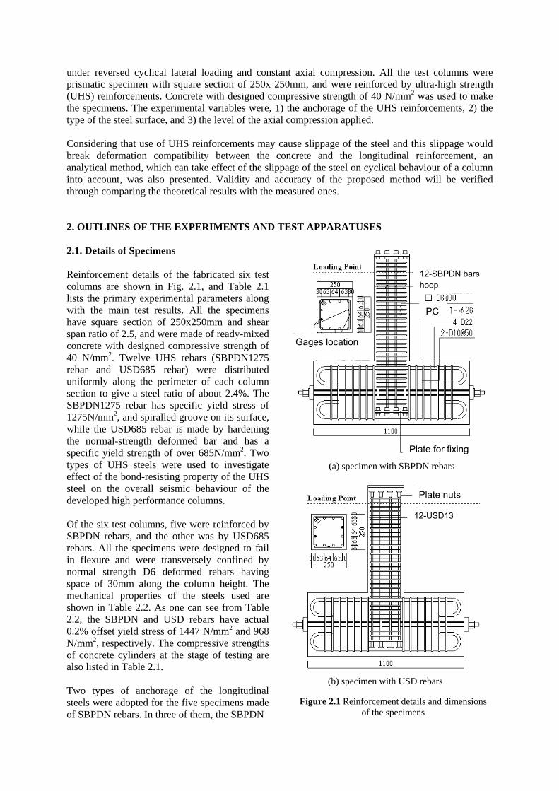
under reversed cyclical lateral loading and constant axial compression. All the test columns were prismatic specimen with square section of 250x 250mm, and were reinforced by ultra-high strength (UHS) reinforcements. Concrete with designed compressive strength of 40 N/mm2 was used to make the specimens. The experimental variables were, 1) the anchorage of the UHS reinforcements, 2) the type of the steel surface, and 3) the level of the axial compression applied. Considering that use of UHS reinforcements may cause slippage of the steel and this slippage would break deformation compatibility between the concrete and the longitudinal reinforcement, an analytical method, which can take effect of the slippage of the steel on cyclical behaviour of a column into account, was also presented. Validity and accuracy of the proposed method will be verified through comparing the theoretical results with the measured ones. 2. OUTLINES OF THE EXPERIMENTS AND TEST APPARATUSES 2.1. Details of Specimens Reinforcement details of the fabricated six test columns are shown in Fig. 2.1, and Table 2.1 lists the primary experimental parameters along with the main test results. All the specimens have square section of 250x250mm and shear span ratio of 2.5, and were made of ready-mixed concrete with designed compressive strength of 40 N/mm2. Twelve UHS rebars (SBPDN1275 rebar and USD685 rebar) were distributed uniformly along the perimeter of each column section to give a steel ratio of about 2.4%. The SBPDN1275 rebar has specific yield stress of 1275N/mm2, and spiralled groove on its surface, while the USD685 rebar is made by hardening the normal-strength deformed bar and has a specific yield strength of over 685N/mm2. Two types of UHS steels were used to investigate effect of the bond-resisting property of the UHS steel on the overall seismic behaviour of the developed high performance columns. Of the six test columns, five were reinforced by SBPDN rebars, and the other was by USD685 rebars. All the specimens were designed to fail in flexure and were transversely confined by normal strength D6 deformed rebars having space of 30mm along the column height. The mechanical properties of the steels used are shown in Table 2.2. As one can see from Table 2.2, the SBPDN and USD rebars have actual 0.2% offset yield stress of 1447 N/mm2 and 968 N/mm2, respectively. The compressive strengths of concrete cylinders at the stage of testing are also listed in Table 2.1. Two types of anchorage of the longitudinal steels were adopted for the five specimens made of SBPDN rebars. In three of them, the SBPDN
Plate nuts
12-USD13
12-SBPDN bars hoop
Gages location
Plate for fixing
PC
(a) specimen with SBPDN rebars
(b) specimen with USD rebars
Figure 2.1 Reinforcement details and dimensionsof the specimens
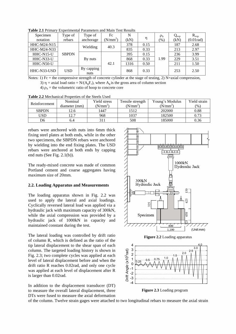
Table 2.1 Primary Experimental Parameters and Main Test Results Specimen notation
Type of rebars
Type of anchorage
Fc (N/mm2)
N (kN) h
(%) Qexp (kN)
Rexp (0.01rad)
HHC-M24-N15 378 0.15 187 2.68 HHC-M24-N33
Wielding 40.3 835 0.33 213 2.97
HHC-N15-U 395 0.15 236 3.99 HHC-N33-U 868 0.33 229 3.51 HHC-N50-U
SBPDN By nuts
1316 0.50 211 1.50
HHC-N33-USD USD By capping
nuts
42.1
868 0.33
1.99
253 2.50
Notes: 1) Fc = the compressive strength of concrete cylinder at the stage of testing, 2) N=axial compression, 3) = axial load ratio = N/(AgFc), where Ag is the gross area of column section 4) h = the volumetric ratio of hoop to concrete core Table 2.2 Mechanical Properties of the Steels Used
Reinforcement Nominal
diameter (mm) Yield stress
(N/mm2) Tensile strength
(N/mm2) Young’s Modulus
(N/mm2) Yield strain
(%) SBPDN 12.6 1447 1512 202000 0.88
USD 12.7 968 1037 182500 0.73 D6 6.4 311 508 185000 0.36
rebars were anchored with nuts into 6mm thick fixing steel plates at both ends, while in the other two specimens, the SBPDN rebars were anchored by wielding into the end fixing plates. The USD rebars were anchored at both ends by capping end nuts (See Fig. 2.1(b)). The ready-mixed concrete was made of common Portland cement and coarse aggregates having maximum size of 20mm. 2.2. Loading Apparatus and Measurements The loading apparatus shown in Fig. 2.2 was used to apply the lateral and axial loadings. Cyclically reversed lateral load was applied via a hydraulic jack with maximum capacity of 300kN, while the axial compression was provided by a hydraulic jack of 1000kN in capacity and maintained constant during the test. The lateral loading was controlled by drift ratio of column R, which is defined as the ratio of the tip lateral displacement to the shear span of each column. The targeted loading history is shown in Fig. 2.3; two complete cycles was applied at each level of lateral displacement before and when the drift ratio R reaches 0.02rad, and only one cycle was applied at each level of displacement after R is larger than 0.02rad. In addition to the displacement transducer (DT) to measure the overall lateral displacement, three DTs were fused to measure the axial deformation of the column. Twelve strain gages were attached to two longitudinal rebars to measure the axial strain
Figure 2.2 Loading apparatus
Figure 2.3 Loading program
-4-3-2-101234
Drif
t Ang
le (
x102 ra
d)
0.250.5 0.75
2.02.5
1.51.0
4.03.0
of the steels located at extreme tensile and compressive sides along height of column, and six strain gages were provided to measure the transverse strain of the hoops located at three specific locations, that had distances from the column bottom of 30mm, 150mm, and 270mm, respectively. 3. EXPERIMENTAL RESULTS AND DISCUSSIONS 3.1 Observed Overall Behaviours Fig. 3.1 shows crack patterns of all specimens observed at drift ratio R reached 0.03rad.. For the two specimens HHC-M24-N15 and HHC-M24-N33, whose SBPDN rebars were fixed at both ends by wielding, no serious damage was observed until R reached 0.015rad., where the concrete cover began to spall off. As the drift ratio R increased, spalling-off of the concrete cover became apparent along with the flexural and shear cracks, but the bond-slipping cracks were not observed till the end of test. Almost cracks and spalling-off of the cover concrete concentrated within column end range about 1.0D, where D is the depth of column section, and the higher the axial compression, the more serious the spalling-off of the concrete shell. Specimen HHC-M24-N15 and HHC-M24-N33 reached their maximum lateral loads at R=0.027 rad and 0.029rad., respectively, and then their lateral load carrying capacities began to decrease due to the rupture of the wielding portion of rebars. Of the other four specimens whose rebars were anchored by nuts, the threes made of SBPDN rebars exhibited overall behaviours similar to those of specimens HHC-M24-N15 and HHC-M24-N33 till R= 0.02 rad.. Spalling-off of the cover concrete was first observed as R approached 0.015 rad., and progressed from the flexural cracks first observed at the end region to the shear cracks diagonally spreading at an angle of about 45 degree within hinge region having 1.0D in length for specimens HHC-N15-U and HHC-N33-U. For the specimen HHC-N50-U under high axial compression, the flexural and shear cracks remained within the end region of about 1.0D, while some vertical bond slipping cracks were observed and spread outside the 1.0D hinge region when drift ratio R became larger than 0.02rad.. It is noteworthy from Fig. 3.1 that use of ultra high strength USD rebars may cause more severe damage to concrete columns than the SBPDN rebars. Comparing the crack patterns of specimens HHC-N33-U and HHC-N33-USD at R=0.03rad., it is obvious that the specimen utilizing the USD rebars has more widely-spread flexural and shear cracks and more severe spalling-off of the cover concrete. This is mainly attributed to the high bond-resisting capacity of the USD rebar. According to the study by Funato (2012), the bond-resisting capacity of the USD rebar reached about 15 N/mm2, which is about five times of that of the SBPDN rebar. The higher bond-resisting capacity assures rebars to work with surrounding concrete as one, but does increase the interaction stress between the rebar and the concrete, and inducing severe damage to the concrete. 3.2 Measured Lateral Force versus Drift Ratio Relationships The measured lateral load V versus drift ratio R relationships for the specimens whose rebars were anchored at ends by nuts are shown in Fig. 3.2, and the measured V-R hysteretic loops of the specimen
HHC-M24-N15 HHC-M24-N33 HHC-N15-U HHC-N33-U HHC-N50-U HHC-N33-USD
Figure 3.1 Cracks and damages observed at R=0.03rad.
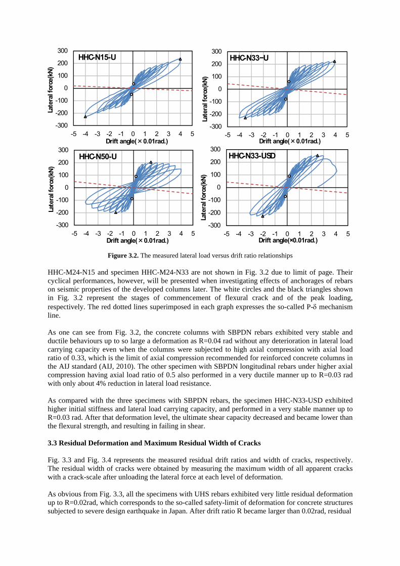
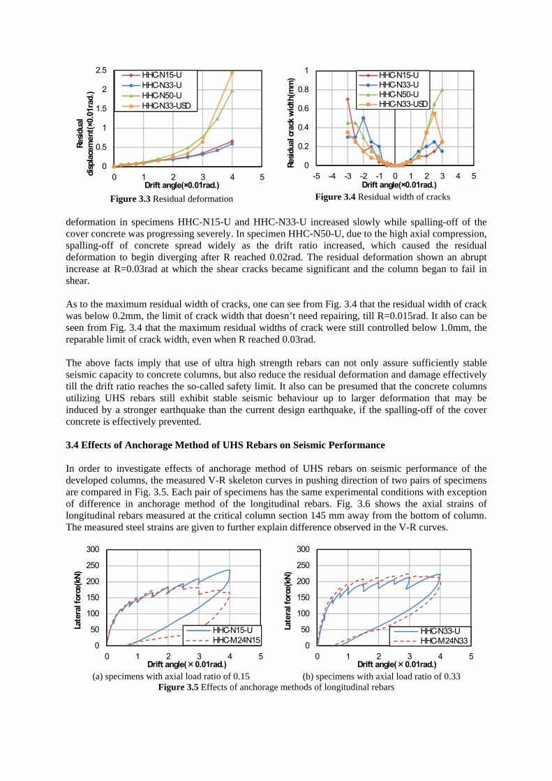
Figure 3.2. The measured lateral load versus drift ratio relationships HHC-M24-N15 and specimen HHC-M24-N33 are not shown in Fig. 3.2 due to limit of page. Their cyclical performances, however, will be presented when investigating effects of anchorages of rebars on seismic properties of the developed columns later. The white circles and the black triangles shown in Fig. 3.2 represent the stages of commencement of flexural crack and of the peak loading, respectively. The red dotted lines superimposed in each graph expresses the so-called P- mechanism line. As one can see from Fig. 3.2, the concrete columns with SBPDN rebars exhibited very stable and ductile behaviours up to so large a deformation as R=0.04 rad without any deterioration in lateral load carrying capacity even when the columns were subjected to high axial compression with axial load ratio of 0.33, which is the limit of axial compression recommended for reinforced concrete columns in the AIJ standard (AIJ, 2010). The other specimen with SBPDN longitudinal rebars under higher axial compression having axial load ratio of 0.5 also performed in a very ductile manner up to R=0.03 rad with only about 4% reduction in lateral load resistance. As compared with the three specimens with SBPDN rebars, the specimen HHC-N33-USD exhibited higher initial stiffness and lateral load carrying capacity, and performed in a very stable manner up to R=0.03 rad. After that deformation level, the ultimate shear capacity decreased and became lower than the flexural strength, and resulting in failing in shear. 3.3 Residual Deformation and Maximum Residual Width of Cracks Fig. 3.3 and Fig. 3.4 represents the measured residual drift ratios and width of cracks, respectively. The residual width of cracks were obtained by measuring the maximum width of all apparent cracks with a crack-scale after unloading the lateral force at each level of deformation. As obvious from Fig. 3.3, all the specimens with UHS rebars exhibited very little residual deformation up to R=0.02rad, which corresponds to the so-called safety-limit of deformation for concrete structures subjected to severe design earthquake in Japan. After drift ratio R became larger than 0.02rad, residual
-300
-200
-100
0
100
200
300
-5 -4 -3 -2 -1 0 1 2 3 4 5
Late
ral f
orce
(kN
)
Drift angle(×0.01rad.)
HHC-N15-U
-300
-200
-100
0
100
200
300
-5 -4 -3 -2 -1 0 1 2 3 4 5
Late
ral f
orce
(kN
)
Drift angle(×0.01rad.)
HHC-N33−U
-300
-200
-100
0
100
200
300
-5 -4 -3 -2 -1 0 1 2 3 4 5
Late
ral f
orce
(kN
)
Drift angle(×0.01rad.)
HHC-N50-U
-300
-200
-100
0
100
200
300
-5 -4 -3 -2 -1 0 1 2 3 4 5
Late
ral f
orce
(kN
)
Drift angle(×0.01rad.)
HHC-N33-USD
0
0.5
1
1.5
2
2.5
0 1 2 3 4 5
Res
idua
l di
spla
cem
ent(
×0.0
1rad
.)
Drift angle(×0.01rad.)
HHC-N15-UHHC-N33-UHHC-N50-UHHC-N33-USD
0
0.2
0.4
0.6
0.8
1
-5 -4 -3 -2 -1 0 1 2 3 4 5
Res
idua
l cra
ck w
idth
(mm
)
Drift angle(×0.01rad.)
HHC-N15-UHHC-N33-UHHC-N50-UHHC-N33-USD
Figure 3.3 Residual deformation Figure 3.4 Residual width of cracks
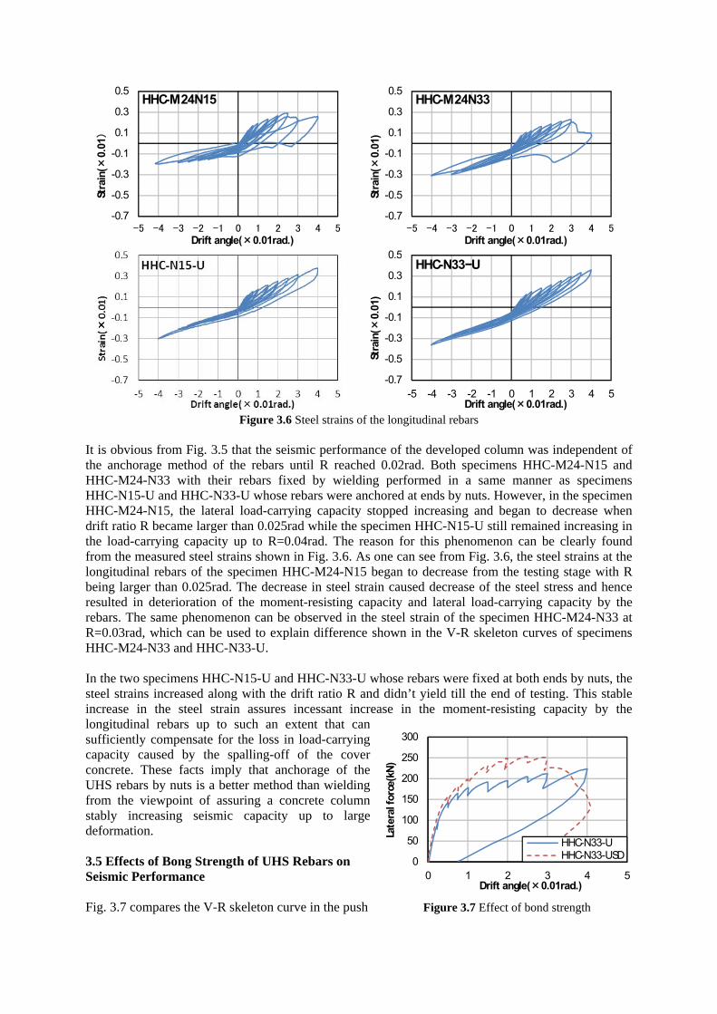
deformation in specimens HHC-N15-U and HHC-N33-U increased slowly while spalling-off of the cover concrete was progressing severely. In specimen HHC-N50-U, due to the high axial compression, spalling-off of concrete spread widely as the drift ratio increased, which caused the residual deformation to begin diverging after R reached 0.02rad. The residual deformation shown an abrupt increase at R=0.03rad at which the shear cracks became significant and the column began to fail in shear. As to the maximum residual width of cracks, one can see from Fig. 3.4 that the residual width of crack was below 0.2mm, the limit of crack width that doesn’t need repairing, till R=0.015rad. It also can be seen from Fig. 3.4 that the maximum residual widths of crack were still controlled below 1.0mm, the reparable limit of crack width, even when R reached 0.03rad. The above facts imply that use of ultra high strength rebars can not only assure sufficiently stable seismic capacity to concrete columns, but also reduce the residual deformation and damage effectively till the drift ratio reaches the so-called safety limit. It also can be presumed that the concrete columns utilizing UHS rebars still exhibit stable seismic behaviour up to larger deformation that may be induced by a stronger earthquake than the current design earthquake, if the spalling-off of the cover concrete is effectively prevented. 3.4 Effects of Anchorage Method of UHS Rebars on Seismic Performance In order to investigate effects of anchorage method of UHS rebars on seismic performance of the developed columns, the measured V-R skeleton curves in pushing direction of two pairs of specimens are compared in Fig. 3.5. Each pair of specimens has the same experimental conditions with exception of difference in anchorage method of the longitudinal rebars. Fig. 3.6 shows the axial strains of longitudinal rebars measured at the critical column section 145 mm away from the bottom of column. The measured steel strains are given to further explain difference observed in the V-R curves.
0
50
100
150
200
250
300
0 1 2 3 4 5
Late
ral f
orce
(kN
)
Drift angle(×0.01rad.)
HHC-N15-UHHC-M24N15
(a) specimens with axial load ratio of 0.15
0
50
100
150
200
250
300
0 1 2 3 4 5
Late
ral f
orce
(kN
)
Drift angle(×0.01rad.)
HHC-N33-UHHC-M24N33
(b) specimens with axial load ratio of 0.33 Figure 3.5 Effects of anchorage methods of longitudinal rebars
-0.7
-0.5
-0.3
-0.1
0.1
0.3
0.5
-5 -4 -3 -2 -1 0 1 2 3 4 5
Stra
in(×
0.01
)
Drift angle(×0.01rad.)
HHC-M24N15
-0.7
-0.5
-0.3
-0.1
0.1
0.3
0.5
-5 -4 -3 -2 -1 0 1 2 3 4 5
Stra
in(×
0.01
)
Drift angle(×0.01rad.)
HHC-M24N33
-0.7
-0.5
-0.3
-0.1
0.1
0.3
0.5
-5 -4 -3 -2 -1 0 1 2 3 4 5
Stra
in(×
0.01
)
Drift angle(×0.01rad.)
HHC-N33−U
Figure 3.6 Steel strains of the longitudinal rebars
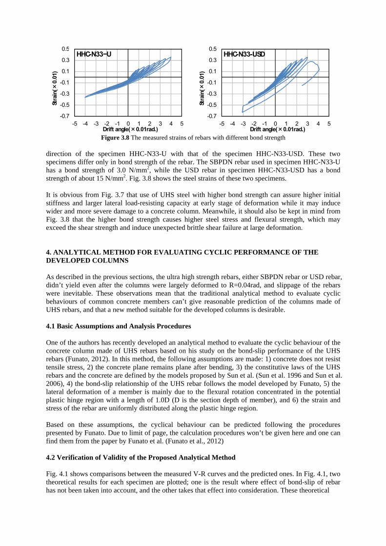
It is obvious from Fig. 3.5 that the seismic performance of the developed column was independent of the anchorage method of the rebars until R reached 0.02rad. Both specimens HHC-M24-N15 and HHC-M24-N33 with their rebars fixed by wielding performed in a same manner as specimens HHC-N15-U and HHC-N33-U whose rebars were anchored at ends by nuts. However, in the specimen HHC-M24-N15, the lateral load-carrying capacity stopped increasing and began to decrease when drift ratio R became larger than 0.025rad while the specimen HHC-N15-U still remained increasing in the load-carrying capacity up to R=0.04rad. The reason for this phenomenon can be clearly found from the measured steel strains shown in Fig. 3.6. As one can see from Fig. 3.6, the steel strains at the longitudinal rebars of the specimen HHC-M24-N15 began to decrease from the testing stage with R being larger than 0.025rad. The decrease in steel strain caused decrease of the steel stress and hence resulted in deterioration of the moment-resisting capacity and lateral load-carrying capacity by the rebars. The same phenomenon can be observed in the steel strain of the specimen HHC-M24-N33 at R=0.03rad, which can be used to explain difference shown in the V-R skeleton curves of specimens HHC-M24-N33 and HHC-N33-U. In the two specimens HHC-N15-U and HHC-N33-U whose rebars were fixed at both ends by nuts, the steel strains increased along with the drift ratio R and didn’t yield till the end of testing. This stable increase in the steel strain assures incessant increase in the moment-resisting capacity by the longitudinal rebars up to such an extent that can sufficiently compensate for the loss in load-carrying capacity caused by the spalling-off of the cover concrete. These facts imply that anchorage of the UHS rebars by nuts is a better method than wielding from the viewpoint of assuring a concrete column stably increasing seismic capacity up to large deformation. 3.5 Effects of Bong Strength of UHS Rebars on Seismic Performance Fig. 3.7 compares the V-R skeleton curve in the push
0
50
100
150
200
250
300
0 1 2 3 4 5
Late
ral f
orce
(kN
)
Drift angle(×0.01rad.)
HHC-N33-UHHC-N33-USD
Figure 3.7 Effect of bond strength
-0.7
-0.5
-0.3
-0.1
0.1
0.3
0.5
-5 -4 -3 -2 -1 0 1 2 3 4 5
Stra
in(×
0.01
)
Drift angle(×0.01rad.)
HHC-N33−U
-0.7
-0.5
-0.3
-0.1
0.1
0.3
0.5
-5 -4 -3 -2 -1 0 1 2 3 4 5
Stra
in(×
0.01
)
Drift angle(×0.01rad.)
HHC-N33-USD
Figure 3.8 The measured strains of rebars with different bond strength
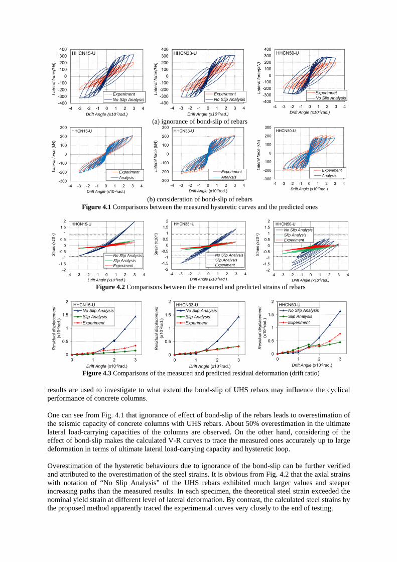
direction of the specimen HHC-N33-U with that of the specimen HHC-N33-USD. These two specimens differ only in bond strength of the rebar. The SBPDN rebar used in specimen HHC-N33-U has a bond strength of 3.0 N/mm2, while the USD rebar in specimen HHC-N33-USD has a bond strength of about 15 N/mm2. Fig. 3.8 shows the steel strains of these two specimens. It is obvious from Fig. 3.7 that use of UHS steel with higher bond strength can assure higher initial stiffness and larger lateral load-resisting capacity at early stage of deformation while it may induce wider and more severe damage to a concrete column. Meanwhile, it should also be kept in mind from Fig. 3.8 that the higher bond strength causes higher steel stress and flexural strength, which may exceed the shear strength and induce unexpected brittle shear failure at large deformation. 4. ANALYTICAL METHOD FOR EVALUATING CYCLIC PERFORMANCE OF THE DEVELOPED COLUMNS As described in the previous sections, the ultra high strength rebars, either SBPDN rebar or USD rebar, didn’t yield even after the columns were largely deformed to R=0.04rad, and slippage of the rebars were inevitable. These observations mean that the traditional analytical method to evaluate cyclic behaviours of common concrete members can’t give reasonable prediction of the columns made of UHS rebars, and that a new method suitable for the developed columns is desirable. 4.1 Basic Assumptions and Analysis Procedures One of the authors has recently developed an analytical method to evaluate the cyclic behaviour of the concrete column made of UHS rebars based on his study on the bond-slip performance of the UHS rebars (Funato, 2012). In this method, the following assumptions are made: 1) concrete does not resist tensile stress, 2) the concrete plane remains plane after bending, 3) the constitutive laws of the UHS rebars and the concrete are defined by the models proposed by Sun et al. (Sun et al. 1996 and Sun et al. 2006), 4) the bond-slip relationship of the UHS rebar follows the model developed by Funato, 5) the lateral deformation of a member is mainly due to the flexural rotation concentrated in the potential plastic hinge region with a length of 1.0D (D is the section depth of member), and 6) the strain and stress of the rebar are uniformly distributed along the plastic hinge region. Based on these assumptions, the cyclical behaviour can be predicted following the procedures presented by Funato. Due to limit of page, the calculation procedures won’t be given here and one can find them from the paper by Funato et al. (Funato et al., 2012) 4.2 Verification of Validity of the Proposed Analytical Method Fig. 4.1 shows comparisons between the measured V-R curves and the predicted ones. In Fig. 4.1, two theoretical results for each specimen are plotted; one is the result where effect of bond-slip of rebar has not been taken into account, and the other takes that effect into consideration. These theoretical
-400
-300
-200
-100
0
100
200
300
400
-4 -3 -2 -1 0 1 2 3 4
Late
ral f
orce
(kN
)
Drift Angle (x10-2rad.)
HHCN15-U
ExperimentNo Slip Analysis
-400
-300
-200
-100
0
100
200
300
400
-4 -3 -2 -1 0 1 2 3 4
La
tera
l fo
rce
(kN
)
Drift Angle (x10-2rad.)
HHCN33-U
ExperimentNo Slip Analysis -400
-300
-200
-100
0
100
200
300
400
-4 -3 -2 -1 0 1 2 3 4
La
tera
l forc
e(k
N)
Drift Angle (x10-2rad.)
HHCN50-U
ExperimnetNo Slip Analysis
(a) ignorance of bond-slip of rebars
-300
-200
-100
0
100
200
300
-4 -3 -2 -1 0 1 2 3 4
Late
ral f
orce
(kN
)
Drift Angle (x10-2rad.)
HHCN15-U
ExperimentAnalysis
-300
-200
-100
0
100
200
300
-4 -3 -2 -1 0 1 2 3 4
Late
ral f
orce
(kN
)
Drift Angle (x10-2rad.)
HHCN33-U
ExperimentAnalysis -300
-200
-100
0
100
200
300
-4 -3 -2 -1 0 1 2 3 4
Late
ral f
orc
e (k
N)
Drift Angle (x10-2rad.)
HHCN50-U
ExperimentAnalysis
(b) consideration of bond-slip of rebars Figure 4.1 Comparisons between the measured hysteretic curves and the predicted ones
-2
-1.5
-1
-0.5
0
0.5
1
1.5
2
-4 -3 -2 -1 0 1 2 3 4
Str
ain
(x10
-2)
Drift Angle (x10-2rad.)
HHCN15-U
No Slip AnalysisSlip AnalysisExperiment
-2
-1.5
-1
-0.5
0
0.5
1
1.5
2
-4 -3 -2 -1 0 1 2 3 4
Str
ain
(x10
-2)
Drift Angle (x10-2rad.)
HHCN33−U
No Slip AnalysisSlip AnalysisExperiment
-2
-1.5
-1
-0.5
0
0.5
1
1.5
2
-4 -3 -2 -1 0 1 2 3 4
Str
ain
(x10
-2)
Drift Angle (x10-2rad.)
HHCN50-U
No Slip AnalysisSlip AnalysisExperiment
Figure 4.2 Comparisons between the measured and predicted strains of rebars
0
0.5
1
1.5
2
0 1 2 3
Res
idua
l dis
plac
emen
t(x
10-
2 rad
.)
Drift Angle (x10-2rad.)
HHCN15-UNo Slip Analysis
Slip Analysis
Experiment
0
0.5
1
1.5
2
0 1 2 3
Res
idua
l dis
plac
emen
t(x
10-2
rad.
)
Drift Angle (x10-2rad.)
HHCN33-UNo Slip Analysis
Slip Analysis
Experiment
0
0.5
1
1.5
2
0 1 2 3
Res
idua
l dis
plac
emen
t (x
10-2
rad.
)
Drift Angle (x10-2rad.)
HHCN50-UNo Slip Analysis
Slip Analysis
Experiment
Figure 4.3 Comparisons of the measured and predicted residual deformation (drift ratio) results are used to investigate to what extent the bond-slip of UHS rebars may influence the cyclical performance of concrete columns. One can see from Fig. 4.1 that ignorance of effect of bond-slip of the rebars leads to overestimation of the seismic capacity of concrete columns with UHS rebars. About 50% overestimation in the ultimate lateral load-carrying capacities of the columns are observed. On the other hand, considering of the effect of bond-slip makes the calculated V-R curves to trace the measured ones accurately up to large deformation in terms of ultimate lateral load-carrying capacity and hysteretic loop. Overestimation of the hysteretic behaviours due to ignorance of the bond-slip can be further verified and attributed to the overestimation of the steel strains. It is obvious from Fig. 4.2 that the axial strains with notation of “No Slip Analysis” of the UHS rebars exhibited much larger values and steeper increasing paths than the measured results. In each specimen, the theoretical steel strain exceeded the nominal yield strain at different level of lateral deformation. By contrast, the calculated steel strains by the proposed method apparently traced the experimental curves very closely to the end of testing.
The importance of consideration of bond-slip can also be clearly observed from comparisons between the measured and theoretical residual deformations shown in Fig. 4.3. As drift ratio R exceeded 0.015 rad, the theoretical residual deformations obtained by ignorance of bond-slip of the UHS rebars began to differ the measured ones, and the difference between them became more and more significant along with the increase of the deformation. This fact implies that ignorance of bond-slip tends to give unreasonable prediction to the residual deformation for concrete columns with UHS rebars. However, in addition to the good agreement observed in the V-R hysteretic curves, the proposed analytical method also predicts the residual deformation of the developed columns very well, which means that the proposed method can provide an useful and powerful tool for structural engineers to conduct reasonable and reliable ultimate capacity design for concrete columns with UHS rebars. 5. CONCLUDING REMARKS To develop a new type of high seismic performance concrete structures, use of ultra high-strength steel as longitudinal rebar of concrete column was proposed. Experimental and theoretical studies were conducted to investigate cyclic behaviours of the new type of columns. Based on the study described in this paper, the following conclusions can be drawn: 1) Utilization of UHS rebars can assure both stable increase in lateral load-resisting capacity and low
residual deformation of a concrete column up to such a large deformation as drift ratio R=0.03rad when the column is subjected to high axial compression with axial load ratio of 0.33.
2) The higher the bond strength of the UHS rebar used, the larger the initial stiffness and ultimate lateral load-carrying capacity of the column. At large deformation incurred by a mega-earthquake, however, use of the UHS rebar with the same bond strength as the normal-strength deformed rebar may cause unexpected brittle shear failure due to larger steel stress.
3) The proposed analytical method can predict the cyclic behaviour of the developed concrete columns very well in terms of the hysteretic loop, the ultimate load-carrying capacity, the residual deformation, and the steel strain.
AKCNOWLEDGEMENT The ultra high strength rebars were provided by Neturen Co. Ltd and Tokyo Rope MFG. Co. Ltd. Their support is greatly appreciated. REFERENCES Architectural Institute of Japan (AIJ, 2010). AIJ Standard for Structural Calculation of Reinforced Concrete
Structures, Maruzen Co. Ltd. (in Japanese) Funato, Y(2012). Seismic Evaluation of Concrete Columns reinforced with ultra high strength rebars having
spiralled grooves on surface by considring effect of bond-slip of the rebars, thesis paper submitted to Kobe univesity for master degree in engineering. (in Japanese)
Funato, Y. and Sun, Y. et al.(2012). Modeling and Application of Bond-Slip Relationship for Ultra High Strength Rebars, Transaction of the Japan Concrete Institute, Vol. 2, (in Japanese, to be published)
Sun, Y. et al. (1996). Flexural Behaviour of High Strength RC Columns Confined by Rectilinear Reinforcement, Journal of Structural and Construction Engineering, Architectural Institute of Japan, No. 486, pp. 95-106.
Sun, Y. et al. (2006). Modeling of Complete Stress-Strain Relationship for High-Strength Steels, The First European Conference on Earthquake and Seismology, Paper No. 760 (10 pages)
Sun, Y. et al. (2006). Analytical Study of Cyclic Response of Concrete Members Made of High-Strength Materials, the Eightth U.S. National Conference on Earthquake Engineering, Paper No. 1581 (10 pages)