dynamical simulation of red blood cell ... - … · dynamical simulation of red blood cell rheology...
TRANSCRIPT

INTERNATIONAL JOURNAL OF c© 2009 Institute for ScientificNUMERICAL ANALYSIS AND MODELING Computing and InformationVolume 6, Number 3, Pages 455–473
DYNAMICAL SIMULATION OF RED BLOOD CELL
RHEOLOGY IN MICROVESSELS
TSORNG-WHAY PAN AND TONG WANG
This paper is dedicated to Professor Roland Glowinski for his 70th birthday
Abstract. A spring model is applied to simulate the skeleton structure
of the red blood cell (RBC) membrane and to study the red blood cell
(RBC) rheology in microvessels. The biconcave RBC shape in static
plasma and tank-treading behavior of single cell in shear flows have
been successfully captured in this model. The behavior of the RBC in a
Poiseuille flow and the lateral migration of the cells in a shear flow have
been investigated. It is found that the RBCs exhibit parachute shape in
a Poiseuille flow with the curvature closely related to the deformability
of the cell membrane and the hematocrit (Hct) of the blood. With this
spring model, RBCs can recover their initial shapes associated with the
minimal elastic energy when the flow stops. The simulation results also
show that the RBCs migrate to the center of the domain in the radial
direction in a shear flow, which clearly indicates the Fahraeus-Lindqvist
effect in microvessels. The rate of migration toward the center depends
on the shape of the RBC; the bioconcave shape enhences this migration.
Key Words. Computational Biomechanics, Microcirculation, Rheol-
ogy, Red blood cells, Elastic membrane model, Immersed boundary
method.
1. Introduction
The microcirculation, which is comprised of the microvessels of diametersmaller than 100µm, is essential to the human body. It is where exchangeof mass and energy takes place. At the microcirculatory level, the partic-ulate nature of the blood becomes significant. The rheological property ofthe red blood cells (RBCs) is a key factor of the blood flow characteristicsin microvessels because of their large volume fraction (40-45%), so calledhematocrit (Hct), in the whole blood. Under normal conditions, RBCs arebiconcave-shaped discs of about 8µm in diameter. The cell membrane ishighly deformable so that RBC can change its shape when an external forceis acting on it and returns to the biconcave resting shape after the removal ofthe forces [13]. In microvessels having internal diameter close to the cell size,
Received by the editors October 30, 2008 and, in revised form, January 5, 2009.2000 Mathematics Subject Classification. 65M60, 76M10, 76Z05.The authors acknowledge the support of NSF (grants ECS-9527123, CTS-9873236,
DMS-9973318, CCR-9902035, DMS-0209066, DMS-0443826).
455

456 T.-W. PAN AND T. WANG
the RBCs exhibit well known parachute shapes under flow [31]. In a biggermicrovessel, RBCs tend to move across the streamlines of the flow, so calledlateral migration, to the center of the vessel so that there is a cell-free layernear the vessel wall. The non-uniform distribution of hematocrit within thecross-section of the vessel is the physical reason of Fahraeus-Lindqvist effect[12] which is characterized by a decrease in the apparent blood viscosity insuch microvessels.
As in [5], in silico mathematical modeling is an attractive alternative sinceit is difficult to deal with in vivo and in vitro experiments on studyingmicrocirculation and RBC rheology due to the size limitation. Nowadays,numerical study of RBC rheology has attracted growing interest (see, e.g.,[28]). For example, in [29] the parachute shape of RBCs in capillaries wasinvestigated with different Hct and the apparent blood viscosity in capillarieswas also studied by using the boundary-integral method with both Mooney-Rivlin and Skalak models plus bending resistance for the RBC membrane.In [11], an immersed boundary method was used to simulate 3D capsule andRBCs in shear flow with both neo-Hookean and Skalak models for membranedeformation. It was found that the bending resistance must be includedin order to simulate complex shape of RBCs when they deform in shearflow. In [2], an immersed boundary method and a neo-Hookean model withand without bending resistance were used to simulate the interaction oftwo deformable cells in a shear flow in two dimensions. It was found thataggregates made of deformable cells are easily breakable by a shear flow,while those made of less deformable cells are not. In [20, 22], an immersedfinite element method was presented for the simulation of RBCs in threedimensions while the RBC membrane employing a Mooney-Rivlin model.The microscopic mechanism of RBC aggregation has been linked to themacroscopic blood viscosity via direct numerical simulation and the relationbetween the effective viscosity of blood flow and the diameters of capillarieshas been obtained. In [33], a semi-implicit particle method combined with aspring model was used to simulate a single file of RBCs between two parallelplates for various Hct in two dimensions. The parachute shape of RBCs incapillaries and flow resistance were investigated with different Hct. In [9],a discrete model for the RBC membrane has been constructed by takinginto account the volume constraint of the RBC, the local area constraint oneach triangle element from the mesh for the RBC membrane, the total areaconstraint of the RBC surface, the stretching force between nodes on eachedge of the surface triangle element, and the preferred angle between triangleelements sharing a common edge (the bending resistance). These constraintsgive different forces acting on the nodes on the RBC surface. A lattice-Boltzmann method was combined with this discrete model to simulate 200densely packed RBCs in three dimensional flow.
Among these methodologies and models mentioned above, we want tocombine the immersed boundary method with spring model since we intendto simulate the mixture of deformable and rigid particles in microvessels innear future. We have already developed very efficient methodologies, called
SIMULATION OF RBC RHEOLOGY IN MICROVESSELS 457
distributed Lagrange multiplier/fictitious domain (DLM/FD) methods, forsimulating rigid particles freely moving in Newtonian fluid in three dimen-sions [16, 17, 24]. The DLM/FD methods are closely related to the immersedboundary methods since they both use uniform grids on simple shape com-putational domain and the Lagrange multipliers play similar role as theforce acting on the elastic membrane immersed in fluid for the immersedboundary methods. For modeling the RBC membrane, the general organi-zation of the RBC membrane has been well characterized. The human RBCis a inflated closed membrane filled with a viscous fluid, called cytoplasm.The RBC membrane is a phospholipid bilayer plus the attached glycocalyxat the plasmatic face of the bilayer and a network of spectrins, called thecytoskeleton, fastened to the bilayer at its cytoplasmic face [13, 18]. The cy-toskeleton is an elastic network which has triangular structure (and most ofthese triangles form hexagons) in the network (e.g., see [34]). This particu-lar geometry, as well as the intrinsic elastic properties of the spectrin, allowsthe RBC to be highly deformable and elastic. Due to its special structure,the RBC membrane has strong resistance changes in area/volume and sheardeformation [18]. Therefore, it is of significance to take into considerationthe structure of the RBC membrane skeleton in the study of RBC rheology.Several spring models [8, 9, 10, 18, 30, 33] have been developed to illustratethe structure of the RBC membrane skeleton and to describe the deforma-bility of the RBCs. In this article, the mechanical properties of the RBCmembrane is predicted by a recently proposed elastic spring model whichhas been used in [33]. The simulation presented here is two-dimensional, andthe methodology can be extended to three dimensions without difficulty.
In this article, we present computational simulation of the motion of de-formable RBCs in microvessels. An immersed boundary method based onthe Navier-Stokes equations is adapted for the fluid flow in a two dimen-sional channel. The present simulation uses a solution method incorporatedwith an operator splitting technique and finite element method with a fixedregular triangular mesh so faster solvers can be used for solving the fluidflow which is an important feature needed for simulating three dimensionalflow involving deformable particles. The structure of this paper is as fol-lows: We discuss the elastic spring model and numerical methods in Section2. In Section 3, first we validate the model by reproducing the biconcaveRBC in static plasma and tank-treading phenomenon of single RBC in shearflows and compare the results with the experimental data and existing nu-merical results. Then the shape behavior of RBCs in a Poiseuille flow andlateral migration in a shear flow are studied via numerical simulations. Theconclusions are summarized in Section 4.
2. Models and methods
Let Ω be a bounded rectangular domain filled with blood plasma whichis incompressible, Newtonian, and contains RBCs with the viscosity of thecytoplasm same as that of the blood plasma. For some T > 0, the governing
458 T.-W. PAN AND T. WANG
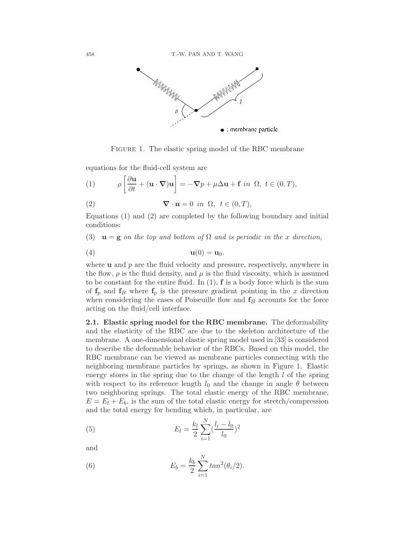
Figure 1. The elastic spring model of the RBC membrane
equations for the fluid-cell system are
(1) ρ
[
∂u
∂t+ (u · ∇)u
]
= −∇p + µ∆u + f in Ω, t ∈ (0, T ),
(2) ∇ · u = 0 in Ω, t ∈ (0, T ),
Equations (1) and (2) are completed by the following boundary and initialconditions:
(3) u = g on the top and bottom of Ω and is periodic in the x direction,
(4) u(0) = u0.
where u and p are the fluid velocity and pressure, respectively, anywhere inthe flow, ρ is the fluid density, and µ is the fluid viscosity, which is assumedto be constant for the entire fluid. In (1), f is a body force which is the sumof fp and fB where fp is the pressure gradient pointing in the x directionwhen considering the cases of Poiseuille flow and fB accounts for the forceacting on the fluid/cell interface.
2.1. Elastic spring model for the RBC membrane. The deformabilityand the elasticity of the RBC are due to the skeleton architecture of themembrane. A one-dimensional elastic spring model used in [33] is consideredto describe the deformable behavior of the RBCs. Based on this model, theRBC membrane can be viewed as membrane particles connecting with theneighboring membrane particles by springs, as shown in Figure 1. Elasticenergy stores in the spring due to the change of the length l of the springwith respect to its reference length l0 and the change in angle θ betweentwo neighboring springs. The total elastic energy of the RBC membrane,E = El + Eb, is the sum of the total elastic energy for stretch/compressionand the total energy for bending which, in particular, are
(5) El =kl
2
N∑
i=1
(li − l0
l0)2
and
(6) Eb =kb
2
N∑
i=1
tan2(θi/2).
SIMULATION OF RBC RHEOLOGY IN MICROVESSELS 459
In equations (5) and (6), N is the total number of the spring elements,and kl and kb are spring constants for changes in length and bending angle,respectively. Based on the principle of virtual work, the elastic spring forceacting on the ith membrane particle is then
(7) Fi = −∂E
∂ri
with ri the position of the ith membrane particle. In the simulation, thiselastic force is a portion of the body force term in the Navier-Stokes equa-tions.
2.2. Immersed boundary method. The immersed boundary methoddeveloped by Peskin, e.g, [25, 26, 27], is employed in this study becauseof its distinguish features in dealing with the problem of fluid flow interact-ing with a flexible fluid/structure interface. Over the years, it has demon-strated its capability in study of computational fluid dynamics includingblood flow. Based on the method, the boundary of the deformable structureis discretized spatially into a set of boundary nodes. The force located at theimmersed boundary node X affects the nearby fluid mesh nodes x througha 2D discrete δ-function Dh(X − x):
(8) F(x) =∑
F(X)Dh(X − x) for |X− x| ≤ 2h,
where h is the uniform finite element mesh size and
(9) Dh(X− x) = δh(X1 − x1)δh(X2 − x2)
with the 1D discrete δ-functions being
(10) δh(z) =
1
4h
(
1 + cos(π · z
2h
))
for |z| ≤ 2h,
0 for |z| > 2h.
The movement of the immersed boundary node X is also affected by thesurrounding fluid and therefore is enforced by summing the velocities at thenearby fluid mesh nodes x weighted by the same discrete δ-function:
(11) U(X) =∑
h2u(x)Dh(X− x) for |X− x| ≤ 2h.
After each time step, the position of the immersed boundary node is updatedby
(12) Xt+∆t = Xt + ∆tU(Xt).
2.3. Operator splitting technique. We first apply the Lie’s scheme [4,16] to equations (1) and (2) with the backward Euler method in time forsome subproblems and obtain the following fractional step subproblems:
u0 = u0 is given; for n ≥ 0, un being known, solve
(13)
ρun+1/3 − un
t+ ∇pn+1/3 = 0 in Ω,
∇ · un+1/3 = 0 in Ω,
un+1/3 = gn+1 on the top and bottom of Ωand is periodic in the x direction,
460 T.-W. PAN AND T. WANG
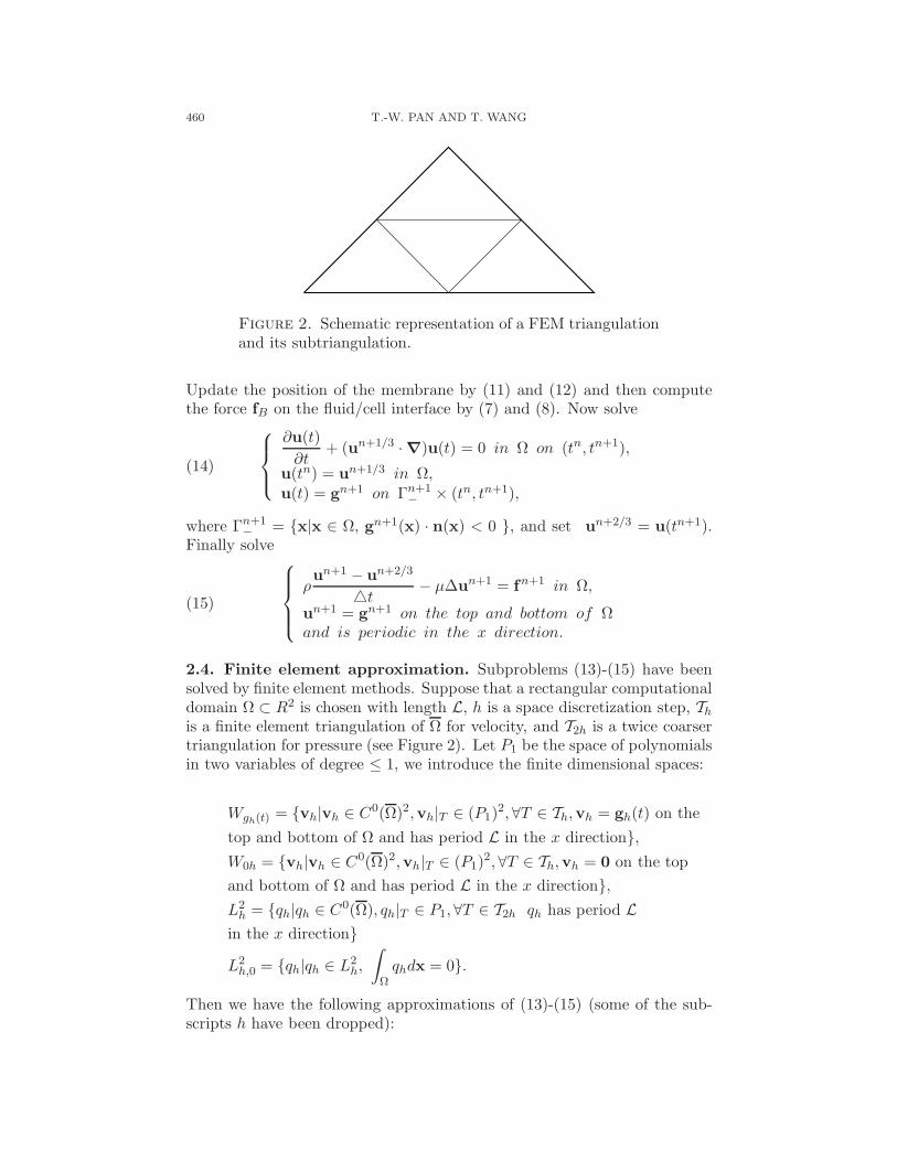
Figure 2. Schematic representation of a FEM triangulationand its subtriangulation.
Update the position of the membrane by (11) and (12) and then computethe force fB on the fluid/cell interface by (7) and (8). Now solve
(14)
∂u(t)
∂t+ (un+1/3 · ∇)u(t) = 0 in Ω on (tn, tn+1),
u(tn) = un+1/3 in Ω,u(t) = gn+1 on Γn+1
−× (tn, tn+1),
where Γn+1−
= x|x ∈ Ω, gn+1(x) · n(x) < 0 , and set un+2/3 = u(tn+1).Finally solve
(15)
ρun+1 − un+2/3
t− µ∆un+1 = fn+1 in Ω,
un+1 = gn+1 on the top and bottom of Ωand is periodic in the x direction.
2.4. Finite element approximation. Subproblems (13)-(15) have beensolved by finite element methods. Suppose that a rectangular computationaldomain Ω ⊂ R2 is chosen with length L, h is a space discretization step, Th
is a finite element triangulation of Ω for velocity, and T2h is a twice coarsertriangulation for pressure (see Figure 2). Let P1 be the space of polynomialsin two variables of degree ≤ 1, we introduce the finite dimensional spaces:
Wgh(t) = vh|vh ∈ C0(Ω)2,vh|T ∈ (P1)2,∀T ∈ Th,vh = gh(t) on the
top and bottom of Ω and has period L in the x direction,
W0h = vh|vh ∈ C0(Ω)2,vh|T ∈ (P1)2,∀T ∈ Th,vh = 0 on the top
and bottom of Ω and has period L in the x direction,
L2h = qh|qh ∈ C0(Ω), qh|T ∈ P1,∀T ∈ T2h qh has period L
in the x direction
L2h,0 = qh|qh ∈ L2
h,
∫
Ωqhdx = 0.
Then we have the following approximations of (13)-(15) (some of the sub-scripts h have been dropped):
SIMULATION OF RBC RHEOLOGY IN MICROVESSELS 461
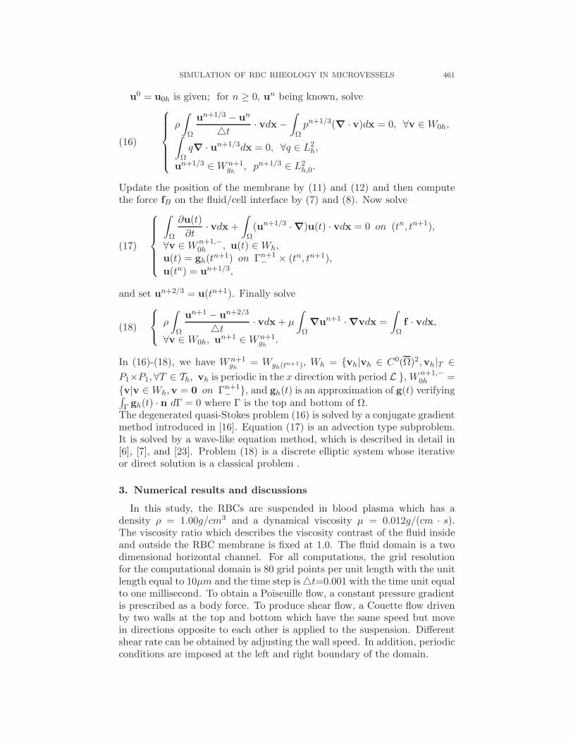
u0 = u0h is given; for n ≥ 0, un being known, solve
(16)
ρ
∫
Ω
un+1/3 − un
t· vdx −
∫
Ωpn+1/3(∇ · v)dx = 0, ∀v ∈ W0h,
∫
Ωq∇ · un+1/3dx = 0, ∀q ∈ L2
h,
un+1/3 ∈ W n+1gh
, pn+1/3 ∈ L2h,0.
Update the position of the membrane by (11) and (12) and then computethe force fB on the fluid/cell interface by (7) and (8). Now solve
(17)
∫
Ω
∂u(t)
∂t· vdx +
∫
Ω(un+1/3 · ∇)u(t) · vdx = 0 on (tn, tn+1),
∀v ∈ W n+1,−0h , u(t) ∈ Wh,
u(t) = gh(tn+1) on Γn+1−
× (tn, tn+1),
u(tn) = un+1/3,
and set un+2/3 = u(tn+1). Finally solve
(18)
ρ
∫
Ω
un+1 − un+2/3
t· vdx + µ
∫
Ω∇un+1 · ∇vdx =
∫
Ωf · vdx,
∀v ∈ W0h, un+1 ∈ W n+1gh
.
In (16)-(18), we have W n+1gh
= Wgh(tn+1), Wh = vh|vh ∈ C0(Ω)2,vh|T ∈
P1×P1,∀T ∈ Th, vh is periodic in the x direction with period L , W n+1,−0h =
v|v ∈ Wh,v = 0 on Γn+1−
, and gh(t) is an approximation of g(t) verifying∫
Γ gh(t) · n dΓ = 0 where Γ is the top and bottom of Ω.The degenerated quasi-Stokes problem (16) is solved by a conjugate gradientmethod introduced in [16]. Equation (17) is an advection type subproblem.It is solved by a wave-like equation method, which is described in detail in[6], [7], and [23]. Problem (18) is a discrete elliptic system whose iterativeor direct solution is a classical problem .
3. Numerical results and discussions
In this study, the RBCs are suspended in blood plasma which has adensity ρ = 1.00g/cm3 and a dynamical viscosity µ = 0.012g/(cm · s).The viscosity ratio which describes the viscosity contrast of the fluid insideand outside the RBC membrane is fixed at 1.0. The fluid domain is a twodimensional horizontal channel. For all computations, the grid resolutionfor the computational domain is 80 grid points per unit length with the unitlength equal to 10µm and the time step is t=0.001 with the time unit equalto one millisecond. To obtain a Poiseuille flow, a constant pressure gradientis prescribed as a body force. To produce shear flow, a Couette flow drivenby two walls at the top and bottom which have the same speed but movein directions opposite to each other is applied to the suspension. Differentshear rate can be obtained by adjusting the wall speed. In addition, periodicconditions are imposed at the left and right boundary of the domain.
462 T.-W. PAN AND T. WANG
3.1. Shape change of a swollen RBC. In many cases of interest, thetwo-dimensional model approximates the shape of the RBC by the charac-teristic cross section in the plane that is parallel to the flow direction if thecell were in shear flow. In the following, the shape change of swollen RBCis simulated using the elastic spring model based on minimum energy prin-ciple as in [33]. Initially, the RBC is assumed to be a circle with a radiusof 2.8µm. The circle is discretized into N = 76 membrane particles so that76 springs are formed by connecting the neighboring particles. The shapechange is stimulated by reducing the total area of the circle s0 through apenalty function
(19) Γs =ks
2(s − se
se)2
and the total energy is modified as E + Γs and the force acting on the ithmembrane particle now is
(20) Fi = −∂(E + Γs)
∂ri
where s and se are the time dependent area of the RBC and the equilib-rium area of the RBC, respectively. When the area is reduced, each RBCmembrane particle moves on the basis of the following equation of motion:
(21) mri + γri = Fi
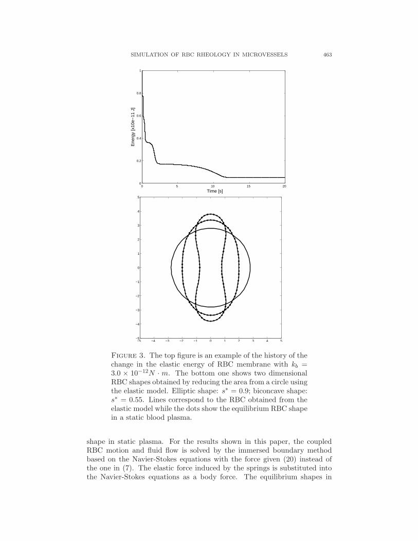
Here, () denotes the time derivative; m and γ represent the membrane par-ticle mass and the membrane viscosity of the RBC. The position ri of theith membrane particle is solved by discretizing (21) via a second order finitedifference method. The total energy stored in the membrane decreases asthe time elapses. The final shape of the RBC shown in Figure 3 is obtainedas the total elastic energy is minimized.
The parameters in the simulation of the shape change of the RBCs are setas follows: the membrane particle mass m is 2.0 × 10⁻⁴g as in [33] and themembrane viscosity γ is 8.8 × 10⁻⁷N · s/m obtained in [21]. The bendingconstant was taken as kb = 0.6−4.8×10⁻¹²N ·m in [33]. Here, the membraneparameters kl and kb are set to be in the range of 0.01 − 3.0 × 10⁻¹²N · mwith kl = kb and the spring length can be kept almost constant with thischoice of parameters (see Section 3.2). The penalty coefficient ks in (19)is about kb × 104. The bending constant is closely related to the rigidityof the membrane. A higher kb results a less deformable cell. Also when kl
is about 10 times smaller of kb (at least for those kb used in this article),the final shape is still circular. An initial circular shape is transformed intoits final stable shape (see Figure 3) associated with a minimal energy fora given area ratio s∗ regardless the choice of kb in the above given range.It is found that when the reduced area s∗ = se/s0 ≤ 0.8, biconcave shapesare obtained. When the ratio s∗ > 0.8, the final stable shape is close to anellipse. The biconcave shape obtained for s∗ = 0.55 resembles the normalphysiological shape of the RBC very well.
After obtaining the shape of the RBC for a given reduced areas, suchRBC shape is put into a 20µm × 20µm domain to obtain its equilibrium
SIMULATION OF RBC RHEOLOGY IN MICROVESSELS 463
0 5 10 15 200
0.2
0.4
0.6
0.8
1
Time [s]
Ene
rgy
[x10
e−11
J]
−5 −4 −3 −2 −1 0 1 2 3 4 5−5
−4
−3
−2
−1
0
1
2
3
4
5
Figure 3. The top figure is an example of the history of thechange in the elastic energy of RBC membrane with kb =3.0 × 10⁻¹²N · m. The bottom one shows two dimensionalRBC shapes obtained by reducing the area from a circle usingthe elastic model. Elliptic shape: s∗ = 0.9; biconcave shape:s∗ = 0.55. Lines correspond to the RBC obtained from theelastic model while the dots show the equilibrium RBC shapein a static blood plasma.
shape in static plasma. For the results shown in this paper, the coupledRBC motion and fluid flow is solved by the immersed boundary methodbased on the Navier-Stokes equations with the force given (20) instead ofthe one in (7). The elastic force induced by the springs is substituted intothe Navier-Stokes equations as a body force. The equilibrium shapes in
464 T.-W. PAN AND T. WANG
plasma shown in Figure 3 demonstrate that the RBCs simulated by elasticspring model are stable in blood plasma.
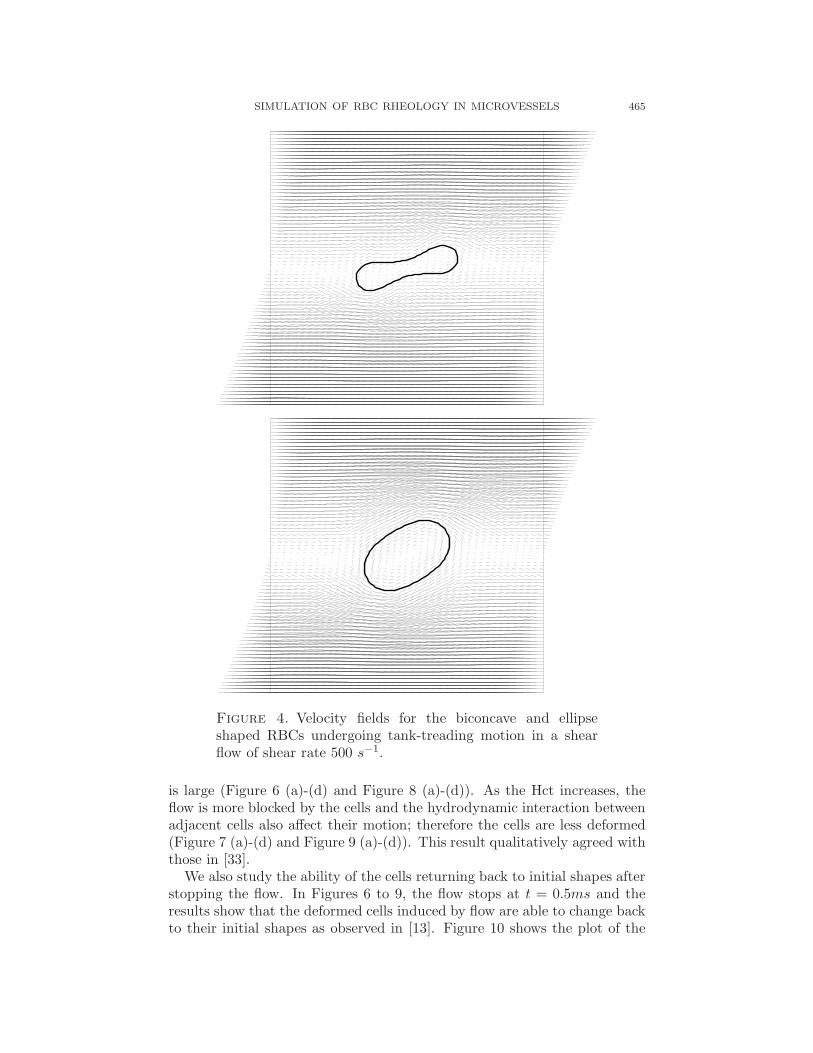
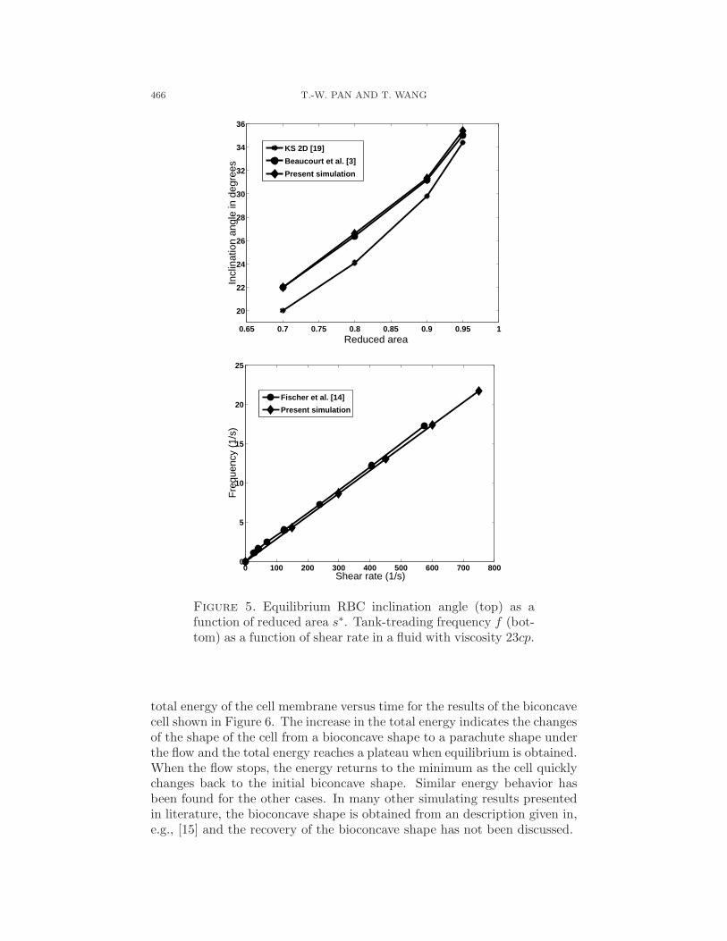
3.2. Tank-treading in shear flows. Tank-treading of RBC membrane inshear flow has been observed experimentally by Fischer et al. [14] and manyothers, e.g., [32]. It was observed that at equilibrium, although the globalshape of the RBC is stationary, the membrane circulates along the contourlike a tank tread with the cell orientating to a fixed inclination angle. It wasalso found that the tank-treading frequency was dependent on the shear rateand the viscosity of the surrounding viscous fluid [14]. We place the RBCobtained in static blood plasma with kb in the range given in the previoussection at the center in shear flow with dimension of 20µm × 20µm. Figure4 shows the velocity fields for the biconcave and ellipse shaped RBCs whenthey are in a tank-trading motion in a shear flow of shear rate 500 s−1. InFigure 5, the elastic spring model is validated by comparing with previousexperimental data [14], theoretical KS model [19], and simulations [3] forthe inclination angles and tank-treading frequencies of RBC in shear flows.From Figure 5, we can see that our simulation results agree very well withthose calculated by [3] for the inclination angles and with experimental data[14] for the tank-treading frequency. The small discrepancy between thesimulation results and the theoretical prediction for the inclination anglesmay be due to the fact that the KS theory was based on the study ofellipsoidal shape instead of biconcave shape in [19]. We also keep track ofthe cell area and perimeter during the simulations. The change is less than±0.1% in the area and less than ±0.5% in the perimeter.
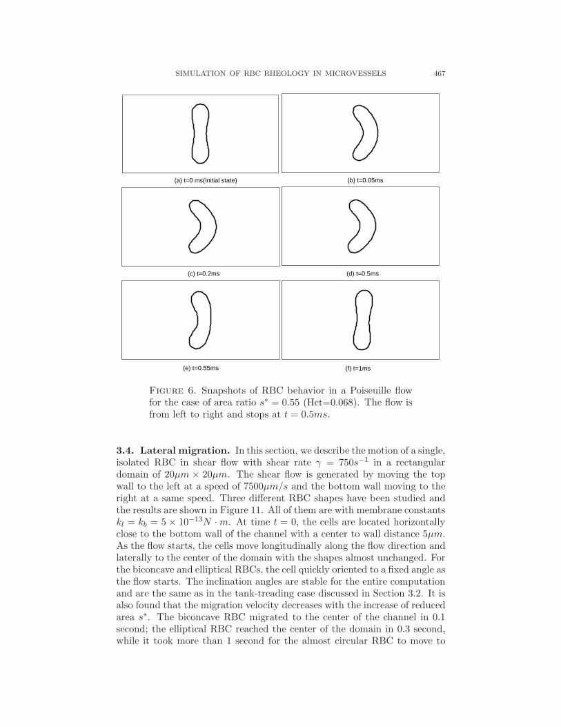
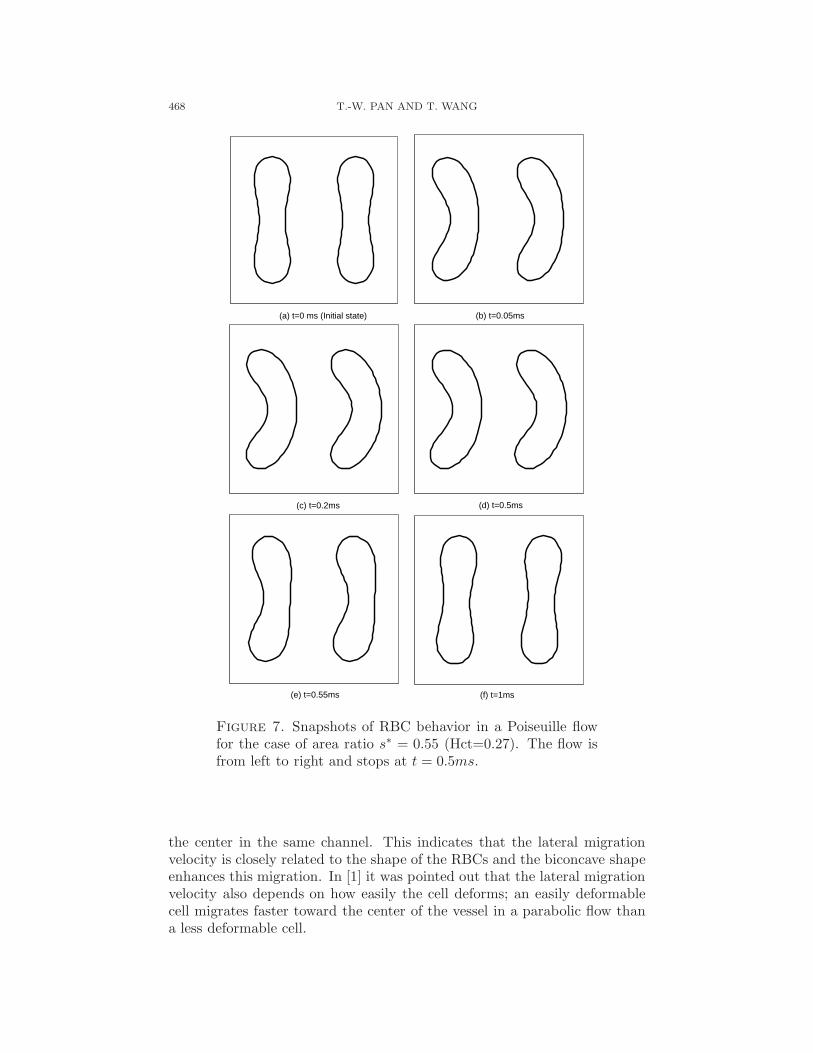
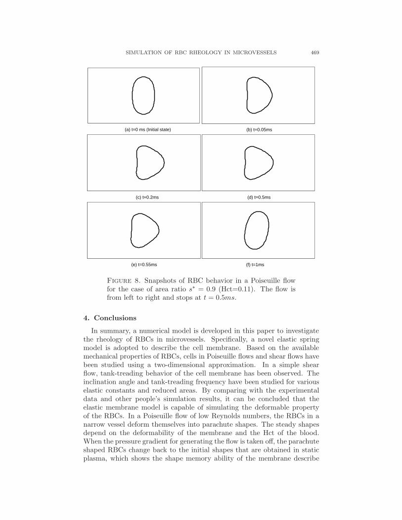
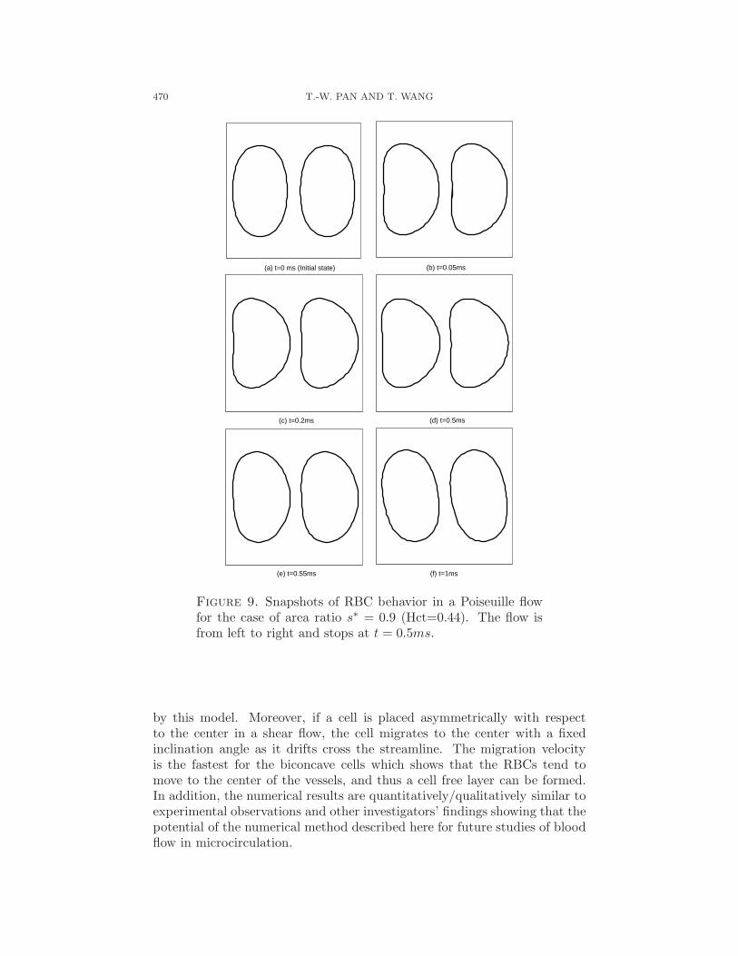
3.3. Shape behavior in a Poiseuille flow. We now present the resultsof the simulation of shape behavior of RBCs in a Poiseuille flow through anarrow channel. The flow is from left to right. The pressure gradient is setas constant for this study so that the Reynolds number for the Poiseuilleflow at the inlet is about 0.17 and the particle Reynolds numbers will beRe < 1. The cells studied are biconcave (resp., elliptical) shape with reducedarea s∗ = 0.55 (resp., s∗ = 0.9). The membrane constants are set to be5×10−13N ·m with kl = kb. In Figures 6 and 8, the fluid domain is 20µm×10µm with single RBC placed in the center of the domain initially. Becauseof the periodic boundary condition at the inflow and outflow boundaries, thisconfiguration conresponds to a hematocrit Hct=0.068 (resp., Hct=0.11) forthe biconcave RBC (resp., the ellipse RBC). In Figures 7 and 9, the fluiddomain is 10µm × 10µm with two RBCs initially placed parallel to eachother with center to center distance 5µm. This configuration conrespondsto a hematocrit Hct=0.27 (resp., Hct=0.44) for the biconcave RBC (resp.,the ellipse RBC). As shown in Figures 6 to 9 (from (a) to (d)), the well knownparachute shape of RBCs has been observed for all the four cases. Moreover,the results demonstrated that the shape of the RBCs in a Poiseuille flow isclosely related to the Hct of the blood. When the Hct is low, the cells are farfrom each other and the flow has the chance to develop after passing each cell.The cells are mainly influenced by the viscous force and the shape change
SIMULATION OF RBC RHEOLOGY IN MICROVESSELS 465
Figure 4. Velocity fields for the biconcave and ellipseshaped RBCs undergoing tank-treading motion in a shearflow of shear rate 500 s−1.
is large (Figure 6 (a)-(d) and Figure 8 (a)-(d)). As the Hct increases, theflow is more blocked by the cells and the hydrodynamic interaction betweenadjacent cells also affect their motion; therefore the cells are less deformed(Figure 7 (a)-(d) and Figure 9 (a)-(d)). This result qualitatively agreed withthose in [33].
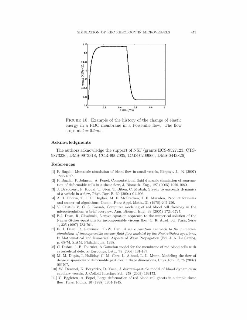
We also study the ability of the cells returning back to initial shapes afterstopping the flow. In Figures 6 to 9, the flow stops at t = 0.5ms and theresults show that the deformed cells induced by flow are able to change backto their initial shapes as observed in [13]. Figure 10 shows the plot of the
466 T.-W. PAN AND T. WANG
0.65 0.7 0.75 0.8 0.85 0.9 0.95 1
20
22
24
26
28
30
32
34
36
Reduced area
Incl
inat
ion
angl
e in
deg
rees
KS 2D [19]
Beaucourt et al. [3]
Present simulation
0 100 200 300 400 500 600 700 8000
5
10
15
20
25
Shear rate (1/s)
Fre
quen
cy (
1/s)
Fischer et al. [14]
Present simulation
Figure 5. Equilibrium RBC inclination angle (top) as afunction of reduced area s∗. Tank-treading frequency f (bot-tom) as a function of shear rate in a fluid with viscosity 23cp.
total energy of the cell membrane versus time for the results of the biconcavecell shown in Figure 6. The increase in the total energy indicates the changesof the shape of the cell from a bioconcave shape to a parachute shape underthe flow and the total energy reaches a plateau when equilibrium is obtained.When the flow stops, the energy returns to the minimum as the cell quicklychanges back to the initial biconcave shape. Similar energy behavior hasbeen found for the other cases. In many other simulating results presentedin literature, the bioconcave shape is obtained from an description given in,e.g., [15] and the recovery of the bioconcave shape has not been discussed.
SIMULATION OF RBC RHEOLOGY IN MICROVESSELS 467
(a) t=0 ms(Initial state)
(b) t=0.05ms
(c) t=0.2ms (d) t=0.5ms
(e) t=0.55ms (f) t=1ms
Figure 6. Snapshots of RBC behavior in a Poiseuille flowfor the case of area ratio s∗ = 0.55 (Hct=0.068). The flow isfrom left to right and stops at t = 0.5ms.
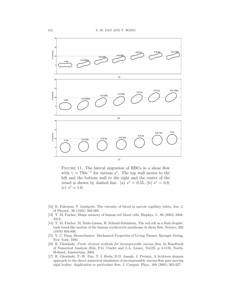
3.4. Lateral migration. In this section, we describe the motion of a single,isolated RBC in shear flow with shear rate γ = 750s−1 in a rectangulardomain of 20µm × 20µm. The shear flow is generated by moving the topwall to the left at a speed of 7500µm/s and the bottom wall moving to theright at a same speed. Three different RBC shapes have been studied andthe results are shown in Figure 11. All of them are with membrane constantskl = kb = 5 × 10⁻¹³N · m. At time t = 0, the cells are located horizontallyclose to the bottom wall of the channel with a center to wall distance 5µm.As the flow starts, the cells move longitudinally along the flow direction andlaterally to the center of the domain with the shapes almost unchanged. Forthe biconcave and elliptical RBCs, the cell quickly oriented to a fixed angle asthe flow starts. The inclination angles are stable for the entire computationand are the same as in the tank-treading case discussed in Section 3.2. It isalso found that the migration velocity decreases with the increase of reducedarea s∗. The biconcave RBC migrated to the center of the channel in 0.1second; the elliptical RBC reached the center of the domain in 0.3 second,while it took more than 1 second for the almost circular RBC to move to
468 T.-W. PAN AND T. WANG
(a) t=0 ms (Initial state)
(b) t=0.05ms
(c) t=0.2ms (d) t=0.5ms
(e) t=0.55ms (f) t=1ms
Figure 7. Snapshots of RBC behavior in a Poiseuille flowfor the case of area ratio s∗ = 0.55 (Hct=0.27). The flow isfrom left to right and stops at t = 0.5ms.
the center in the same channel. This indicates that the lateral migrationvelocity is closely related to the shape of the RBCs and the biconcave shapeenhances this migration. In [1] it was pointed out that the lateral migrationvelocity also depends on how easily the cell deforms; an easily deformablecell migrates faster toward the center of the vessel in a parabolic flow thana less deformable cell.
SIMULATION OF RBC RHEOLOGY IN MICROVESSELS 469
(a) t=0 ms (Initial state)
(b) t=0.05ms
(c) t=0.2ms (d) t=0.5ms
(e) t=0.55ms (f) t=1ms
Figure 8. Snapshots of RBC behavior in a Poiseuille flowfor the case of area ratio s∗ = 0.9 (Hct=0.11). The flow isfrom left to right and stops at t = 0.5ms.
4. Conclusions
In summary, a numerical model is developed in this paper to investigatethe rheology of RBCs in microvessels. Specifically, a novel elastic springmodel is adopted to describe the cell membrane. Based on the availablemechanical properties of RBCs, cells in Poiseuille flows and shear flows havebeen studied using a two-dimensional approximation. In a simple shearflow, tank-treading behavior of the cell membrane has been observed. Theinclination angle and tank-treading frequency have been studied for variouselastic constants and reduced areas. By comparing with the experimentaldata and other people’s simulation results, it can be concluded that theelastic membrane model is capable of simulating the deformable propertyof the RBCs. In a Poiseuille flow of low Reynolds numbers, the RBCs in anarrow vessel deform themselves into parachute shapes. The steady shapesdepend on the deformability of the membrane and the Hct of the blood.When the pressure gradient for generating the flow is taken off, the parachuteshaped RBCs change back to the initial shapes that are obtained in staticplasma, which shows the shape memory ability of the membrane describe
470 T.-W. PAN AND T. WANG
(a) t=0 ms (Initial state)
(b) t=0.05ms
(c) t=0.2ms (d) t=0.5ms
(e) t=0.55ms (f) t=1ms
Figure 9. Snapshots of RBC behavior in a Poiseuille flowfor the case of area ratio s∗ = 0.9 (Hct=0.44). The flow isfrom left to right and stops at t = 0.5ms.
by this model. Moreover, if a cell is placed asymmetrically with respectto the center in a shear flow, the cell migrates to the center with a fixedinclination angle as it drifts cross the streamline. The migration velocityis the fastest for the biconcave cells which shows that the RBCs tend tomove to the center of the vessels, and thus a cell free layer can be formed.In addition, the numerical results are quantitatively/qualitatively similar toexperimental observations and other investigators’ findings showing that thepotential of the numerical method described here for future studies of bloodflow in microcirculation.
SIMULATION OF RBC RHEOLOGY IN MICROVESSELS 471
0 0.2 0.4 0.6 0.8 10.8
0.85
0.9
0.95
1
1.05
1.1
1.15
Time (ms)
Ene
rgy
( X
10e−
11 J
)
Figure 10. Example of the history of the change of elasticenergy in a RBC membrane in a Poiseuille flow. The flowstops at t = 0.5ms.
Acknowledgments
The authors acknowledge the support of NSF (grants ECS-9527123, CTS-9873236, DMS-9973318, CCR-9902035, DMS-0209066, DMS-0443826)
References
[1] P. Bagchi, Mesoscale simulation of blood flow in small vessels, Biophys. J., 92 (2007)1858-1877.
[2] P. Bagchi, P. Johnson, A. Popel, Computational fluid dynamic simulation of aggrega-tion of deformable cells in a shear flow, J. Biomech. Eng., 127 (2005) 1070-1080.
[3] J. Beaucourt, F. Rioual, T. Seon, T. Biben, C. Misbah, Steady to unsteady dynamicsof a vesicle in a flow, Phys. Rev. E, 69 (2004) 011906.
[4] A. J. Chorin, T. J. R. Hughes, M. F. McCracken, J. E. Marsden, Product formulasand numerical algorithms, Comm. Pure Appl. Math., 31 (1978) 205-256.
[5] V. Cristini V, G. S. Kassab, Computer modeling of red blood cell rheology in themicrocirculation: a brief overview, Ann. Biomed. Eng., 33 (2005) 1724-1727.
[6] E.J. Dean, R. Glowinski, A wave equation approach to the numerical solution of theNavier-Stokes equations for incompressible viscous flow, C. R. Acad. Sci. Paris, Serie1, 325 (1997) 783-791.
[7] E. J. Dean, R. Glowinski, T.-W. Pan, A wave equation approach to the numerical
simulation of incompressible viscous fluid flow modeled by the NavierStokes equations.In Mathematical and Numerical Aspects of Wave Propagation (Ed. J. A. De Santo),p. 65-74, SIAM, Philadelphia, 1998.
[8] C. Dubus, J.-B. Fournier, A Gaussian model for the membrane of red blood cells withcytoskeletal defects, Europhys. Lett., 75 (2006) 181-187.
[9] M. M. Dupin, I. Halliday, C. M. Care, L. Alboul, L. L. Munn, Modeling the flow ofdense suspensions of deformable particles in three dimensions, Phys. Rev. E, 75 (2007)066707.
[10] W. Dzwinel, K. Boryczko, D. Yuen, A discrete-particle model of blood dynamics incapillary vessels, J. Colloid Interface Sci., 258 (2003) 163173.
[11] C. Eggleton, A. Popel, Large deformation of red blood cell ghosts in a simple shearflow, Phys. Fluids, 10 (1998) 1834-1845.
472 T.-W. PAN AND T. WANG
0
5
10
15
20
(a)
Y (
mic
ron)
t=0.005st=0s
t=0.05s
t=0.3s t=0.735st=0.1s
t=0.03s
0
5
10
15
20
(b)
Y (
mic
ron)
t=0st=0.005s
t=0.03st=0.05s
t=0.706st=0.3st=0.1s
0
5
10
15
20
(c)
Y (
mic
ron)
t=0.75st=0.3s
t=0.16st=0.1st=0.05st=0s
t=1s
Figure 11. The lateral migration of RBCs in a shear flowwith γ = 750s−1 for various s∗. The top wall moves to theleft and the bottom wall to the right and the center of thevessel is shown by dashed line. (a) s∗ = 0.55, (b) s∗ = 0.9,(c) s∗ = 1.0.
[12] R. Fahraeus, T. Lindqvist, The viscosity of blood in narrow capillary tubes, Am. J.of Physiol., 96 (1931) 562-568.
[13] T. M. Fischer, Shape memory of human red blood cells, Biophys. J., 86 (2004) 3304-3313.
[14] T. M. Fischer, M. Stohr-Liesen, H. Schmid-Schonbein, The red cell as a fluid droplet:tank tread-like motion of the human erythrocyte membrane in shear flow, Science, 202(1978) 894-896.
[15] Y. C. Fung, Biomechanics: Mechanical Properties of Living Tissues, Springer-Verlag,New York, 1993.
[16] R. Glowinski, Finite element methods for incompressible viscous flow. In Handbookof Numerical Analysis (Eds. P.G. Ciarlet and J.-L. Lions), Vol.IX, p 3-1176, North-Holland, Amsterdam, 2003.
[17] R. Glowinski, T.-W. Pan, T. I. Hesla, D.D. Joseph, J. Periaux, A fictitious domainapproach to the direct numerical simulation of incompressible viscous flow past movingrigid bodies: Application to particulate flow, J. Comput. Phys., 169 (2001) 363-427.
SIMULATION OF RBC RHEOLOGY IN MICROVESSELS 473
[18] J. C. Hansen, S. Skalak, A. Hoger, An elastic network model based on the structureof the red blood cell membrane skeleton, Biophys. J.,70 (1996) 146-166.
[19] S. R. Keller, R. Skalak, Motion of a tank-treading ellipsoidal particle in a shear flow,J. Fluid Mech., 120 (1982) 27-47.
[20] W. K. Liu, Y. Liu, D. Farrell, L. Zhang, X. S. Wang, Y. Fukui, N. Patankar, Y.Zhang, C. Bajaj, J. Lee, J. Hong, X. Chen, H. Hsu, Immersed finite element methodand its applications to biological systems, Comput. Methods Appl. Mech. Eng., 195(2006) 1722-1749.
[21] X. Liu , Z.-Y. Tang, Z. Zeng, X. Chen, W.-J. Yao, Z.-Y. Yan, Y. Shi, H.-x. Shan,D.-G. Sun, D.-Q. He, Z.-Y. Wen, The measurement of shear modulus and membranesurface viscosity of RBC membrane with Ektacytometry: A new technique, Math.Biosci., 209 (2007) 190-204.
[22] Y. Liu, W. K. Liu, Rheology of red blood cell aggregation by computer simulation,J. Comput. Phys., 220 (2006) 139-154.
[23] T.-W. Pan, R. Glowinski, A projection/wave-like equation method for the numericalsimulation of incompressible viscous fluid flow modeled by the Navier-Stokes equations,Computational Fluid Dynamics Journal, 9 (2000) 28-42.
[24] T.-W. Pan, D. D. Joseph, R. Bai, R. Glowinski, V. Sarin, Fluidization of 1204 spheres:simulation and experiments, J. Fluid Mech., 451 (2002) 169-191.
[25] C. S. Peskin, Numerical analysis of blood flow in the heart, J. Comput. Phys.,25(1977) 220-252.
[26] C. S. Peskin, The immersed boundary method, Acta Numer., 11 (2002) 479-517.[27] C. S. Peskin, D. M. McQueen, Modeling prosthetic heart valves for numerical analysis
of blood flow in the heart, J. Comput. Phys., 37 (1980) 11332.[28] C. Pozrikidis, Modeling and Simulation of Capsules and Biological Cells, Chapman
& Hall/CRC, Boca Raton, 2003.[29] C. Pozrikidis, Axisymmetric motion of a file of red blood cells through capillaries,
Phys. Fluids, 17 (2005) 031503.[30] T. W. Secomb, B. Styp-Rekowska, A. R. Pries, Two-dimensional simulation of red
blood cell deformation and lateral migration in microvessels, Ann. Biomed. Eng., 35(2007) 755-765.
[31] R. Skalak, P. I. Branemark, Deformation of red blood cells in capillaries, Science, 164(1969) 717-719.
[32] R. Tran-Son-Tay, S. P. Sutera, P. R. Rao, Determination of red blood cell membraneviscosity from rheoscopic observations of tank-treading motion, Biophys. J., 46 (1984)65-72.
[33] K. Tsubota, S. Wada, T. Yamaguchi, Simulation study on effects of hematocrit onblood flow properties using particle method, J. Biomech. Sci. Eng., 1 (2006) 159-170.
[34] C. Vera, R. Skelton, F. Bossens, L. A. Sung, 3-D nanomechanics of an erythrocytejunctional complex in equibiaxial and anisotropic deformations, Ann. Biomed. Eng.,33 (2005) 1387-1404.
Department of Mathematics, University of Houston, Houston, Texas 77204-3008, USAE-mail : [email protected] and [email protected]
URL: http://www.math.uh.edu/∼pan/