dynamic radio resource management in 3gpp lte · dynamic radio resource management in 3gpp lte...
TRANSCRIPT

Blekinge Tekniska Högskola
SE–371 79 Karlskrona
Tel.vx 0455-38 50 00
Fax 0455-38 50 57
1
Thesis Number: MEE09:06
Dynamic Radio Resource
Management in 3GPP LTE
Sajid Hussain
This thesis is presented as part of Degree of
Master of Science in Electrical Engineering
Blekinge Institute of Technology
January 2009
Supervisor: Benny Lövström
School of Egineering
Department of Applied Signal Processing
Blekinge Tekniska Högskola
SE–371 79 Karlskrona
Tel.vx 0455-38 50 00
Fax 0455-38 50 57
2

Blekinge Tekniska Högskola
SE–371 79 Karlskrona
Tel.vx 0455-38 50 00
Fax 0455-38 50 57
3
Abstract
Orthogonal Frequency Division Multiple Access (OFDMA) is specified as downlink
multiple access scheme in 3GPP LTE which divides the available bandwidth into
multiple narrow orthogonal frequency bands. Thus, there is no ISI (Inter Symbol
Interference) within the cell boundary. As the whole frequency spectrum is available in
a cell site there would be greater chance of ICI (Intercell Interference) among the cell
edge users of adjoining cells if frequency bands are allocated without any arrangement.
This ICI can be mitigated with the help of different arrangements of frequency bands
allocations and possibly with different transmission power distinguishing between the
cell centre users and cell edge users.
In this thesis work different ICI mitigation techniques are analyzed with different
frequency allocation schemes and transmission power, and also different radio resource
scheduling algorithms are analysed to enhance bandwidth efficiency and throughput.

Blekinge Tekniska Högskola
SE–371 79 Karlskrona
Tel.vx 0455-38 50 00
Fax 0455-38 50 57
4

Blekinge Tekniska Högskola
SE–371 79 Karlskrona
Tel.vx 0455-38 50 00
Fax 0455-38 50 57
5
Acknowledgement
This thesis work proved to be a challenging task for me as I started to learn about 3GPP
LTE technology after getting impressed from continuously rising popularity in the
cellular broadband world. I learnt many things about LTE and could not decide by
myself about the topic of my research work.
Then luckily I met Jörgen Nordberg, Associate Professor at BTH, who provided me
guidelines on how to select research topic for my research. I really appreciate his
precious recommendations which helped me a lot in moving ahead with my research.
I would like to thanks Sven Johansson for his help in my thesis work.
I would like to thanks also to Benny Lövström, Associate Professor at BTH, and my
supervisor at BTH for his continuous support on the thesis work.
The name that completes this thanks giving story is Mr. Kashif Ali, Strategic Product
Manager, Huawei Technologies AB, Kista. He supported me technically and morally
and pushed me continuously to complete this thesis work and of course, I could be able
to complete this work with his efforts.

Blekinge Tekniska Högskola
SE–371 79 Karlskrona
Tel.vx 0455-38 50 00
Fax 0455-38 50 57
6
Table of Contents
Abstract ...................................................................................................................................................................................3 Acknowledgement ..................................................................................................................................................................5 Table of Contents ...................................................................................................................................................................6 List of abbreviations ..............................................................................................................................................................9 1.0 Introduction ....................................................................................................................................................................11
1.1 Problem Statement .......................................................................................................................................................12 1.2 Scope of thesis work ....................................................................................................................................................13 1.3 Thesis Outline ..............................................................................................................................................................13
2.0 LTE Technical Background ..........................................................................................................................................15 2.1 Multiple Access Techniques ........................................................................................................................................15
2.1.1 Downlink – OFDMA ............................................................................................................................................15 2.1.2 Peak to Average Power Ratio (PAPR) ..................................................................................................................16 2.1.3 Frequency Offset ...................................................................................................................................................16 2.1.4 Uplink – SC-FDMA ..............................................................................................................................................17 2.1.5 SC-FDMA Transmitter .........................................................................................................................................17 2.1.6 SC-FDMA Receiver ..............................................................................................................................................17
2.2 Physical Layer ..............................................................................................................................................................18 2.2.1 Physical Layer Frame Structure ............................................................................................................................19 2.2.2 Downlink Vs Uplink Transmission .......................................................................................................................21 2.2.3 Downlink Transmission Control Tasks .................................................................................................................21 2.2.4 Uplink Transmission Control Tasks......................................................................................................................22
2.3 Layer 2 (MAC, RLC, PDCP) .......................................................................................................................................23 2.3.1 Mapping of logical channel onto physical channel ...............................................................................................23 2.3.2 Segmentation and Reassembly of RLC PDU ........................................................................................................24 2.3.3 Data Delivery Assurance – ARQ/HARQ ..............................................................................................................24 2.3.4 Transport format selection.....................................................................................................................................24
2.4 Layer 3 - RRC ..............................................................................................................................................................25 2.4.1 Intercell Interference Control ................................................................................................................................25 2.4.3 Mobility Management ...........................................................................................................................................25
2.5 Power Control and Dynamic Rate Control...................................................................................................................25 2.6 Radio Resource Scheduling..........................................................................................................................................26
3.0 Previous Work on ICIC and Resource Allocation Algorithms ..................................................................................27 3.1 Intercell Interference Control (ICIC)............................................................................................................................27
3.1.1 Static ICIC.............................................................................................................................................................27 3.1.1.1 Ericsson’s Proposal ........................................................................................................................................27 3.1.1.2 Alcatel’s Proposal...........................................................................................................................................28
3.1.2 Semi-Static ICIC ...................................................................................................................................................29 3.1.2.1 Siemen’s Proposal ..........................................................................................................................................29 3.1.2.2 Softer Frequency Reuse Proposal...................................................................................................................29 3.1.2.3 Proposal based on Users’ Ratio and Multi-Level Frequency Allocation........................................................30
3.2 Resources Scheduling Algorithms ...............................................................................................................................30 3.2.1 Proportional Fairness Resource Allocation Scheme..............................................................................................31 3.2.2 Softer Frequency Reuse based Resource Scheduling Algorithm ..........................................................................31 3.2.3 Round Robin Scheduling Scheme .........................................................................................................................32 3.2.4 Resource Scheduling Scheme based on Maximum Interference...........................................................................32 3.2.5 Resource Scheduling Algorithm based on Dynamic Allocation ...........................................................................33
3.3 Thesis work ..................................................................................................................................................................33 4.0 Design and Implementation...........................................................................................................................................35
4.1 Requirements................................................................................................................................................................35 4.2 Probabilistic Equations.................................................................................................................................................35
4.2.1 Probability of Collisions........................................................................................................................................35 4.2.2 Steady-State Probabilities......................................................................................................................................37
4.2.2.1 Mean Service Time of a call...........................................................................................................................39

Blekinge Tekniska Högskola
SE–371 79 Karlskrona
Tel.vx 0455-38 50 00
Fax 0455-38 50 57
7
4.3 Uplink Power Management..........................................................................................................................................41 4.4 Implementation ............................................................................................................................................................43
4.4.1 Simulation .............................................................................................................................................................43 4.4.2 Simulation Parameters...........................................................................................................................................43
4.4.2.1 Network Traffic ..............................................................................................................................................44 4.4.2.2 Modulation Schemes and Coding Rates.........................................................................................................44 4.4.2.3 Channel Allocation.........................................................................................................................................44 4.4.2.4 User Generation..............................................................................................................................................44
4.5 Performance Metrics ....................................................................................................................................................45 5.0 Performance Analysis ....................................................................................................................................................47
5.1 Intercell Interference Control Schemes ........................................................................................................................47 5.1.1 Static Interference Management with Reuse 1 and Reuse 3..................................................................................47 5.1.2 Dynamic Interference Management Schemes .......................................................................................................49 5.1.3 Partial Isolation Scheme........................................................................................................................................51
5.2 Performance Analysis of Resources Scheduling Algorithms .......................................................................................53 5.2.1 Round Robin Scheme............................................................................................................................................53 5.2.2 Algorithm based on Maximum Interference .........................................................................................................53 5.2.3 Proportional Fairness Scheduling Algorithm ........................................................................................................53 5.2.4 Scheduling Algorithm based on Softer Frequency Reuse .....................................................................................54
6.0 Conclusions .....................................................................................................................................................................55 7.0 Future work ....................................................................................................................................................................56 References .............................................................................................................................................................................57

Blekinge Tekniska Högskola
SE–371 79 Karlskrona
Tel.vx 0455-38 50 00
Fax 0455-38 50 57
8
Blekinge Tekniska Högskola
SE–371 79 Karlskrona
Tel.vx 0455-38 50 00
Fax 0455-38 50 57
9
List of abbreviations
3GPP LTE 3rd
Generation Partnership Project Long Term Evolution E-UTRAN Evolved-UMTS Terrestrial Radio Access Network HSDPA High Speed Downlink Packet Access CS Circuit Switched PS Packet Switched QoS Quality of Service eNodeB Evolved Node Base station OFDMA Orthogonal Frequency Division Multiplexing SISO Single Input Single Output MIMO Multiple Input Multiple Output L2,L3 Layer 2, 3 UE User Equipment SC-FDMA Single Carrier – Frequency Division Multiple Access WiMAX Worldwide Interoperability for Microwave Access WLAN Wireless Local Area Network PAPR Peak to Average Power Ratio BPSK Binary Phase Shift Keying QPSK Quadratic Phase Shift Keying QAM Quadratic Amplitude Modulation DFT Discrete Fourier Transform IDFT Inverse Discrete Fourier Transform RRM Radio Resource Management MAC Medium Access Control FDD/TDD Frequency Division Duplex / Time Division Duplex SFN Single Frequency Network CP Cyclic Prefix CQI Channel Quality Indicator ARQ/HARQ Automatic Repeat Request / Hybrid Automatic Repeat Request AMC Adaptive Modulation Coding ICIC Intercell Interference Co-ordination
Blekinge Tekniska Högskola
SE–371 79 Karlskrona
Tel.vx 0455-38 50 00
Fax 0455-38 50 57
10

Blekinge Tekniska Högskola
SE–371 79 Karlskrona
Tel.vx 0455-38 50 00
Fax 0455-38 50 57
11
Chapter 1
1.0 Introduction
“Out of estimated 1.8 billion people, who will have broadband by 2012, some two third
will be mobile broadband consumers – and majority of these will be served by HSPA
and LTE [8]”
Long Term Evolution (LTE) is the name given to a 3GPP project to evolve UTRAN to
meet the needs of future broadband cellular communications. This project can also be
considered as a milestone towards 4G standardization. Different organizations and
individuals are involved in this project to specify requirements of LTE which satisfies
both operators and consumers. Till the time of writing, it was in the standardization
phase and many of its specifications have been standardized and many companies like
Ericsson and Nortel have developed a prototype of LTE just to demonstrate the
effectiveness of Long Term Evolution.
Following are a few of the requirements on this newly evolving cellular technology,
Long Term Evolution (LTE) [9]
• All-IP Network
One of the main requirements is the transition of circuit-switched (CS) and
packet-switched (PS) networks into an all-IP network which can support different
types of services with different QoS and which also provide the easy integration
with the other communication networks. This will ultimately reduce the
integration cost and provide with the users the seamless integration with other
services.
• Support of scalable bandwidth i.e. 1.25, 2.5, 5, 10, and 20 MHz
The subscribers can be assigned bandwidth as low as 1.25 MHz or as high as 20
MHz and it may also be aggregate assigned the bandwidth of above bands.
• Peak downlink data rates
Users may attain the instantaneous downlink data rate as high as 100 Mbps while
provided 20 MHz bandwidth and uplink data rate of 50 Mbps while provided
with 20 MHz bandwidth.
• Latency of 50-100 msec for C-plane and less than 10 msec for U-plane
• Optimized mobility for speed of less than 15 km/hr, high performance mobility
for speed up to 120 km/hr and mobility support for speed up to 350 km/hr
• Coverage with full performance up to 5km and with slight degradation in
performance for coverage up to 30km and support of coverage of up to 100 km

Blekinge Tekniska Högskola
SE–371 79 Karlskrona
Tel.vx 0455-38 50 00
Fax 0455-38 50 57
12
• Control Plane Capacity
At least 200 users per cell should be supported in active state for allocation of
5MHz spectrum
• Multi-antenna configuration
The multi-antenna configuration will significantly improve the system
performance and service capability and it would be used to achieve the transmit
diversity, multi-stream transmission, and beam forming.
Radio resource management attracts great attention while utilizing available resources
to provide users with enhanced system throughput. Radio resources management
include transmission power management, mobility management, and scheduling of
radio resources. An intelligent radio resource management is at the heart of LTE to
make it a robust technology to meet the broadband mobility needs of upcoming years.
This will schedule the available resource in a best way and provide to the users with the
enough transmission capability to achieve the decided QoS even while they move freely
and also will make sure that these assigned resources would not interfere with already
assigned resources. This will also be of interest that the transmitted signal will reach the
receiver in a good health while utilizing the power efficiently available at the
transmitter.
1.1 Problem Statement
Release 8 of 3GPP proposes that there will be a frequency reuse factor of 1 in an LTE
network i.e. whole the frequency spectrum will be available in a single eNodeB [8]. In
the proposed architecture of LTE it is obvious that there is no central node managing
the resources in a set of eNodeBs [9] and thus distributed radio resource management
has to be done which is more difficult.
3GPP release 8 proposes OFDMA as downlink multiple access technique which utilizes
orthogonal frequencies for individual streams and streams. Thus, there is no intra-cell
interference but there is a large inter-cell interference as adjacent cells have same
frequencies to assign to their users. The cell edge users might be affected badly with
this inter-cell interference.
3GPP release 8 has proposed three different solutions i.e. randomization, cancellation,
and co-ordination, to counter this inter-cell interference problem. ICI randomization
suppresses the interference in the signal, ICI cancellation cancels only the dominating
part of the interfering signal and ICI coordination arrange the frequency allocation in
the network to mitigate as much ICI as possible. Thus, the most appropriate choice is
the intercell interference randomization technique [1].

Blekinge Tekniska Högskola
SE–371 79 Karlskrona
Tel.vx 0455-38 50 00
Fax 0455-38 50 57
13
This thesis will analyze different intercell interference co-ordination schemes and it will
explain the best one and its performance will be evaluated.
An intelligent radio resource management algorithm is also needed for the dynamic
allocation of radio resource. 3GPP LTE specify that radio resources must be
dynamically allocated to its users for 1ms to maintain the decided QoS and also to best
utilize the available spectrum while considering maximum system throughput and
capacity.
This thesis work will also include study of different radio resource allocation
algorithms and will explain the best one and also its performance is investigated.
1.2 Scope of thesis work
This thesis will only consider SISO system and MIMO used to increase the throughput
but it do not have any effect on intercell interference coordination techniques and radio
resource scheduling algorithms.
1.3 Thesis Outline
Technical background of Long Term Evolution (LTE) and related work is discussed in
chapter 2 in which different technical aspects of LTE like downlink and uplink multiple
access scheme, and technical specifications on layer 1-3 etc.
Chapter 3 describes the attempts already made for 3GPP LTE transmission power
management, different inter-cell co-ordination schemes, and different radio resource
algorithms.
Chapter 4 includes design and extraction of the probabilistic equations which will be
used in chapter 5 for analysis of ICIC techniques. It also includes different parameters
important for simulation.
Chapter 5 provides an analysis on the results obtained from chapter 3.
Chapter 6 contains results and conclusions obtained from the analysis concluded in last
chapter.
Future work containing this thesis related issues is discussed in chapter 7.

Blekinge Tekniska Högskola
SE–371 79 Karlskrona
Tel.vx 0455-38 50 00
Fax 0455-38 50 57
14

Blekinge Tekniska Högskola
SE–371 79 Karlskrona
Tel.vx 0455-38 50 00
Fax 0455-38 50 57
15
Chapter 2
2.0 LTE Technical Background
This section contains the discussion on some important technical aspects of 3GPP LTE
release 8 i.e. downlink and uplink multiple access techniques, physical layer, L2, L3,
power management, inter-cell interference mitigation techniques i.e. randomization,
cancellation, and co-ordination.
2.1 Multiple Access Techniques
3GPP LTE have selected different transmission schemes in uplink and downlink due to
certain characteristics. OFDMA has been selected for downlink i.e. from eNodeB to UE
and SC-FDMA has been selected for uplink i.e. for transmission from UE to eNodeB
2.1.1 Downlink – OFDMA
Orthogonal Frequency Division Multiplexing (OFDM) is already employed by cellular
and non-cellular wireless transmissions such as mobile WiMAX and WLAN and is
selected as multiplexing scheme for 3GPP LTE.
OFDM is a spectral efficient transmission scheme in such a way that it divides a high-
bit-rate data stream into several parallel narrowband low-bit-rate data streams often
called sub-carriers or tones. This division is made in such a way that sub-carriers are
orthogonal to each other which eliminates the need of non-overlapping sub-carriers to
avoid inter carrier interference [17].
The first carrier is selected so that its frequency contains integer number of cycles in a
symbol period. In order to make sub-carriers orthogonal to each other, adjacent sub-
carriers are spaced by
BSC = B / L
where
B: nominal bandwidth of high-bit-rate data stream
L: number of sub-carriers

Blekinge Tekniska Högskola
SE–371 79 Karlskrona
Tel.vx 0455-38 50 00
Fax 0455-38 50 57
16
Transmission on orthogonal sub-carriers is fine but only for the ideal situation such as
there is no multi-path delay spread, but usually this situation doesn’t exist in real world.
To make transmission completely ISI free we also need to place a time guard in
between the sub-carriers and their spacing. Making this time guard enough, larger than
the maximum expected delay spread, makes transmission completely ISI free. This time
guard also cause the power and bandwidth wastage and of course decrease the spectrum
efficiency but this is dependent on what the time guard fraction of symbol duration is.
2.1.2 Peak to Average Power Ratio (PAPR)
PAPR is defined as the peak power within one OFDM symbol normalized by the
average signal power [7]. When several OFDM sub-carriers align themselves in phase
there occur a large PAPR which is the most difficult concern in RF engineering of
traditional OFDM.
The value of PAPR is directly proportional to the number of sub-carriers, given by [19]
)log(10)( NdBPAPR ∝
where ‘N’ is the number of sub-carriers
Signals with a large PAPR need highly linear power amplifiers to avoid excessive inter
modulation distortion and to achieve this linearity, amplifiers have to operate with a
large back off from their peak power which results in low power efficiency (measured
by the ratio of transmitted power to the DC power dissipated) [5].
2.1.3 Frequency Offset
Although OFDM is resistant against multi-path fading it requires high degree of
synchronization to maintain its sub-carrier orthogonality. In OFDM, the uncertainty in
carrier frequency, which is due to the difference in the frequencies of local oscillators in
the transmitter and receiver, give rise to a shift in frequency domain which is also called
frequency offset. This frequency offset can also be caused by the Doppler shift effect.
The demodulation of a signal with frequency offset can cause large bit error rate and
might degrade the symbol synchronization performance [6].

Blekinge Tekniska Högskola
SE–371 79 Karlskrona
Tel.vx 0455-38 50 00
Fax 0455-38 50 57
17
2.1.4 Uplink – SC-FDMA
SC-FDMA (Single Carrier – Frequency Division Multiple Access) has been selected as
3GPP LTE uplink transmission technique (MS to eNodeB). It is a modified form of
OFDMA and has similar throughput performance and essentially the same overall
complexity as OFDMA. Like OFDM, SC-FDMA also consists on subcarriers but it
transmits on subcarriers in sequence not in parallel which is the case in OFDM , which
prevents power fluctuations in SC-FDMA signals i.e. low PAPR [5].
In a cellular system with severe multipath propagation environment, SC-FDMA signals
might cause inter symbol interference when they reach at the base station. The base
station uses the adaptive frequency domain equalization to cancel the inter symbol
interference.
As most mobile terminals are empowered with a battery, it is a good idea to perform
some complex operations like frequency domain equalization at base station rather
putting any burden like linear power amplification, on mobile terminal because more
resources are available on base station.
2.1.5 SC-FDMA Transmitter
At the input of transmitter, the binary input is modulated using QPSK, 16QAM or
optionally using 64QAM. Then this modulated input is divided into blocks of N-
symbols using N-point DFT (Discrete Fourier Transform) to convert to frequency
domain representation Xk . Then each of these N-Point DFT output is modulated on
one of orthogonal subcarriers that can be transmitted which results in a set Xl of
complex subcarrier amplitudes. Then M-Point inverse DFT is applied to convert Xl to a
time domain signal Xm. Then each Xm symbol is modulated on a single carrier and
transmitted sequentially after the adding CP (circular prefix) to prevent IBI (inter block
interference), and pulse shaping to reduce out-of-band energy.
2.1.6 SC-FDMA Receiver
The receiver shapes the received signal, removes CP, and then the signal is converted to
frequency domain using M-Point DFT. Then frequency domain equalization is
performed and then these equalized symbols are transformed to time domain using N-
Point IDFT and then detection and decoding take place.
3GPP LTE radio resource management is concerned mainly with physical layer and
MAC sublayer of the layer 2 in the OSI stack. In next sections, RRM technical aspects
of these two layers are discussed.

Blekinge Tekniska Högskola
SE–371 79 Karlskrona
Tel.vx 0455-38 50 00
Fax 0455-38 50 57
18
Figure 1: Transmitter and Receiver structure of SC-FDMA [5]
2.2 Physical Layer
Physical layer provides data transport services to the higher layers with the help of
transport channel via the MAC sub-layer. It is defined in a bandwidth agnostic way i.e.
allowing it to adapt to various spectrum allocations. The main functions of physical
layer include the following [11]
- Transport channel error detection and report to the higher layers
- FEC encoding and decoding
- Transport channel rate adaption to the physical channel
- Transport channel mapping onto the physical channel
- Physical channel modulation/demodulation
- Synchronization of time and frequency
- Reporting radio channel measurements to higher layers
- MIMO antenna signals processing, transmit diversity, and beam forming
Both FDD (Frequency Division Duplex) and TDD (Time Division Duplex) are
supported on physical layer in LTE where downlink and uplink are identified with

Blekinge Tekniska Högskola
SE–371 79 Karlskrona
Tel.vx 0455-38 50 00
Fax 0455-38 50 57
19
different frequencies and timings respectively. Both FDD and TDD share the same
framing structure. This frame has duration of 10 ms and consists of 20 time slots. A
sub-frame is formed by two adjacent time slots and it span to 1ms (i.e. 0.5 ms x 2).
To make the LTE backward compatible with TD SCDMA, an additional framing is
defined for TDD.
Downlink physical channels include the following
- PDSCH (Physical Downlink Shared Channel)
- PDCCH (Physical Downlink Control Channel)
- CCPCH (Common Control Physical Channel)
and the downlink physical channels include the following channels
- PUSCH (Physical Uplink Shared Channel)
- PUCCH (Physical Uplink Control Channel)
LTE downlink/uplink channels other than the broadcast channel have been identified to
use QPSK, 16QAM, or 64QAM while broadcast channel can use only QPSK.
Multiple Input Multiple Output transmission technique has been specified for LTE
downlink deployment in which antenna configuration is represented by N x M where N
(1-4) is the number of transmit antennas and M (1-2) is the number of receive antennas.
MIMO has been specified to exploit the multipath fading so that spatially multiplexed
independent data streams can be transmitted. MIMO implementation will get impaired
in a low multipath distortion environment.
LTE physical layer transmission is deployable in two different modes i.e.
FDD: downlink and uplink are identified with two different frequency bands
TDD: downlink and uplink signals are transmitted in different time slots
2.2.1 Physical Layer Frame Structure
The radio resource block can be seen as a frequency-time grid. Frequency domain is
divided into sub-carriers where each sub-carrier spans 15 KHz. One sub-band is
comprised of 12 sub-carriers.
Time domain can be divided into slots which has duration of 0.5ms. One sub-frame
consists on 2 time slots and has duration of 1ms and 1 frame is consisted on 10 sub-
frame and thus it spans for 10ms (10 * 2 * 0.5ms).
Minimized radio resource block that can be allocated on both uplink and downlink is
called sub-band and contains 12 sub-carriers transmitted in one time slot (0.5ms). Thus,
minimum allowable spectrum is 180 KHz.

Blekinge Tekniska Högskola
SE–371 79 Karlskrona
Tel.vx 0455-38 50 00
Fax 0455-38 50 57
20
12
11
10
9
8
7
6
5
4
3
2
0 1 2 3 4 5 6 7 8 9 10 . . . . . . . 18 29
Figure 2: LTE Time-Frequency grid
CP (Cyclic Prefix) is inserted into the frames at the transmitter and is used to order the
received packets at the receiving end. There are different types of CP i.e. short and long
CP.
In LTE downlink, short CP is transmitted with 7 OFDM symbols in a single time slot
i.e. 0.5ms and is used for unicast transmission while long CP-subframe is has 6 OFDM
symbols and duration of 16.67ms duration and used for multicast transmission. Long
CP supports the implementation of SFN (Single Frequency Network) which is specified
to be used for broadcast transmission.
Time Domain
1 Subband = 12 Sub-carriers
= 12*15 = 180KHz
Subframe = 1ms 1 Frame = 10 Sub-frames = 20ms
Frequency
Domain
Sub-carrier = 15 KHz
Resource Block

Blekinge Tekniska Högskola
SE–371 79 Karlskrona
Tel.vx 0455-38 50 00
Fax 0455-38 50 57
21
2.2.2 Downlink Vs Uplink Transmission
Physical layer downlink transmission is implemented using OFDMA while uplink
transmission uses SC-FDMA. Both OFDMA and SC-FDMA use the same time-
frequency grid, same time slots, sub-frames, frames, sub-carrier, and subband structure
etc.
The differences in OFDMA and SC-FDMA are
- subband is made using the adjacent sub-carriers in SC-FDMA so no need
of CP, while random available subcarriers combines to make subband in
OFDMA so that it can achieve frequency diversity
- Another difference is in the transmission of control signal. In OFDMA one
subcarrier uses 7 OFDM symbols in one time slot to carry data
transmission while in SC-FDMA two short blocks are reserved to carry
pilot signal and 6 are used for data transmission.
LTE also supports its co-existence with the lower generation mobile standards like
GSM and thus it also has special TDD frame structure to support Low-Chip-Rate Time
Division Duplex (LCR-TDD) and High-Chip-Rate Time Division Duplex (HCR-TDD).
2.2.3 Downlink Transmission Control Tasks
Downlink communication includes the transmission of user data and control
information from the eNodeB towards UE and is done using three channels i.e.
- Physical Channel Format Indicator Channel (PCFICH)
- Physical H-ARQ Indicator Channel (PHICH), and
- Physical Downlink Control Channel (PDCCH)
LTE Control tasks include the following among others
- Cell search and Synchronization During cell search different kinds of information are identified like cell ID,
radio frame number, frequency and bandwidth, antenna configuration, and
CP type. Cell search is performed using the physical layer downlink
reference signal which contains the cell identity, and synchronization
signal which is transmitted on the 72 centre sub-carriers within the same

Blekinge Tekniska Högskola
SE–371 79 Karlskrona
Tel.vx 0455-38 50 00
Fax 0455-38 50 57
22
predefined slots. CCPCH is also available for the transmission of
additional information.
X R0 X R0
R0 X R0 X
X R0 X R0
R0 X R0 X
0 6 0 6
Even Symbol | Odd Symbols
X=No transmission, R0=Antenna Port 1 transmission
Antenna 1
R1 X R1 X
X R1 X R1
R1 X R1 X
X R1 X R1
0 6 0 6
Even Symbols | Odd Symbols
X=No transmission, R1=Antenna 2 transmission
Antenna 2
Figure 3 – Downlink reference signal structure (2 Txs) [3GPP TS 36.211S]
- Link adaption
Downlink transmission for share data channels in E-UTRAN is not fixed
but it is adapted using different modulation and coding schemes based on
the measurement reports (CQI) sent by the UE towards eNodeB.
- Scheduling eNodeB performs scheduling on available radio resources and let the UE
know about their allocated time/frequency resources and transmission
formats to be used by UE. RR scheduling is based on UE capability, QoS,
and measurement reports from the UE.
- Hybrid ARQ Hybrid Automatic Repeat Request is used by the user equipment to request
the retransmission of incorrectly received or not received data packets from
eNodeB. 3GPP specified asynchronous H-ARQ in the downlink.
2.2.4 Uplink Transmission Control Tasks
As mentioned above that SC-FDMA is a modified version of OFDMA in which
adjacent resource blocks are allocated to the individuals. Resource blocks are allocated
as multiple of one resource block i.e. 2, 3, and 5 just for the sake of simplicity in DFT
design [12]. PUSCH is used for uplink data transmission and PUCCH carries control
information for the uplink transmission towards eNodeB.

Blekinge Tekniska Högskola
SE–371 79 Karlskrona
Tel.vx 0455-38 50 00
Fax 0455-38 50 57
23
Besides being used in channel estimation at eNodeB, reference signal is used to carry
CQI which is used at eNodeB as base of resource scheduling.
Some important uplink transmission control tasks include the following
- Random Access A preamble of 1 subframe (1ms) long is transmitted on a random channel
to request access to the network using the transmit power calculated with
open loop power control. If no response is received within a fixed time
period another random channel is selected and preamble is transmitted on
that selected channel.
- Link Adaption
Transmit power, modulation, channel coding rate, and transmission
bandwidth are adapted based on CQI.
- Uplink Scheduling Uplink Time/Frequency resources are scheduled in eNodeB based on QoS,
CQ measurements on uplink, and UE capabilities and it buffer status. The
uplink scheduling decision is transmitted to UE on PDCCH.
- Uplink Timing Control Time alignment of UE to eNodeB is necessary for the successful
transmission between them.
- Hybrid ARQ The eNodeB uses uplink H-ARQ to request the UE to retransmit the
incorrectly received data packets. 3GPP specified synchronous H-ARQ to
be used in uplink.
2.3 Layer 2 (MAC, RLC, PDCP)
LTE layer 2 consists of three sublayers named as MAC (Medium Access Control), RLC
(Radio Link Control), and PDCP (Packet Data Convergence Protocol). Following are
few of the Layer 2 functions
2.3.1 Mapping of logical channel onto physical channel
Physical layer provides a transport channel to layer 2 and it provides its RLC
sublayer several logical channels used for several function. The mapping of
these logical channels into physical channel is the responsibility of layer 2.
Blekinge Tekniska Högskola
SE–371 79 Karlskrona
Tel.vx 0455-38 50 00
Fax 0455-38 50 57
24
2.3.2 Segmentation and Reassembly of RLC PDU
The PDUs received at eNodeB to be transmitted towards UE may not be
deliverable because of the PDU size. So, these PDUs are segmented into
PDUs of smaller size and then transmitted towards UE and in the reverse
direction, these PDUs are reassembled into data packets to be transmitted
towards core network. Multiplexing and de-multiplexing of different PDUs
into/from a data packet to be transmitted on physical layer is also L2
responsibility.
2.3.3 Data Delivery Assurance – ARQ/HARQ
Data delivery between the network nodes is assured using ARQ (Automatic
Repeat Request) on layer 2 (RLC, PDCP) while HARQ (Hybrid Automatic
Repeat Request) is used to ensure data delivery between physical layers
(MAC) of corresponding network entities.
HARQ keeps on transmitting certain number of packets and then waits for
ACK (acknowledgement) from the receiving end before it can transmit more
packets. If a NACK is received for a packet then only that packet is
retransmitted.
LTE uses synchronous HARQ in uplink where both parties know the frame in
which HARQ is transmitted while downlink uses asynchronous HARQ.
2.3.4 Transport format selection
Transport format selection includes the selection of coding scheme and
modulation technique which suites best the user requirements and physical
channel condition.
LTE scheduling algorithm allocates the radio resources to the users for initial
transmission. CQI reports (Channel Quality Indicator) are collected from the
UEs and if suddenly channel conditions are much changed then MAC layer
can decide to reallocate network resources for further transmission or it can
restart the transmission by selecting new modulation and coding schemes.
Coding scheme can be select from Turbo Coding and LDPC for data channel
transmission and Turbo or Convolutional Coding for control channel
transmission and modulation scheme can be selected from QPSK, 16QAM,
and 64QAM which suites best the channel condition. QPSK, 16QAM, and
64QAM can transmit 2, 4, and 6 bits per symbol respectively.

Blekinge Tekniska Högskola
SE–371 79 Karlskrona
Tel.vx 0455-38 50 00
Fax 0455-38 50 57
25
An ideal channel condition is that there is a non-zero error rate. Other
functions of L2 include priority handling and ciphering.
2.4 Layer 3 - RRC
RRC (Radio Resource Control) is the 3rd
layer in LTE layering structure. Specifically,
the functions of RRC include the following
2.4.1 Intercell Interference Control
Due to OFDMA no inter channel interference is there in LTE but due to frequency
reuse factor of 1 there might be large intercell interference. 3GPP has specified a
technique called intercell interference co-ordination to reduce ICI. This is discussed in
detail in the next chapters.
2.4.3 Mobility Management
RRC is also responsible mobility management in RRC_IDLE and RRC_CONNECTED
states. Other functions of RRC include Admission Control and Load Balancing etc.
2.5 Power Control and Dynamic Rate Control
Power control is very important in the varying signal strength channel conditions to
maintain the required signal to noise ratio (Eb/N0). In principle, the transmission power
is increased by the power controller at the base station in the poor channel condition so
that the signal may be reached at the receiver in good enough condition and it decreases
the transmission power in a good channel condition.
The power control is very important in real time applications like voice and multimedia
services which bear very low transmission errors. But, in other data services like FTP it
is of less importance as these services require the transmission with data rate as high as
possible.
Dynamic Rate Control is used for data services which do not require constant data rate
but a maintained signal to noise ratio is required for the successful communication.
Dynamic rate control is inversely proportional to the power control. The data rate is
increased in the good transmission conditions and in the bad channel conditional the
data rate is decreased to maintain the required signal to noise ratio (Eb/N0).
The signal to noise ratio Eb/N0 can be increased by increasing data rate and data rate can
be increased up to a certain level because of the bandwidth limitation. The modern
technologies like LTE have adapted efficient methods to increase the data with the
limited bandwidth.

Blekinge Tekniska Högskola
SE–371 79 Karlskrona
Tel.vx 0455-38 50 00
Fax 0455-38 50 57
26
In LTE data rate is dynamically controlled by assigning the different modulation
schemes and/or turbo coding with different rates. Modulation scheme can be chosen
from QPSK, 16QAM, or 64QAM depending on the transmission channel condition
where QPSK is on the lowest level and 64QAM is on the top. The turbo coding rate can
be any value between 0 and 1. In the good channel condition the higher modulation
scheme can be utilized and higher turbo coding rate. Dynamic rate control is also
referred to as Adaptive Modulation and Coding (AMC) in LTE.
2.6 Radio Resource Scheduling
Radio resource scheduling is a process in which resource blocks are distributed among
the UEs. Before the eNodeB can assign the modulation technique and coding rate to an
UE, based on the transmission channel condition, it must be assigned radio resource
blocks. The details of RRB are given in section 2.2.1.
Due to the rapidly and instantaneously changing nature of radio channel quality there
must be a fast enough scheduling algorithm to compensate the changing channel
conditions.
Radio resources are scheduled every 1ms in 3GPP LTE and different frequency
bandwidths i.e. 1.25, 2.5, 5, 10, 15, 20 MHz or an aggregated bandwidth can be
assigned to an individual user based on the channel condition and availability. Thus, the
task of the scheduling in 3GPP LTE i.e. RRBs distribution among users, is more
complex.

Blekinge Tekniska Högskola
SE–371 79 Karlskrona
Tel.vx 0455-38 50 00
Fax 0455-38 50 57
27
Chapter 3
3.0 Previous Work on ICIC and Resource Allocation
Algorithms
3.1 Intercell Interference Control (ICIC)
Three main approaches to inter-cell interference mitigation are currently being
considered : intercell interference cancellation, randomization, and coordination [1].
Cancellation only suppresses the intercell interference at UE beyond what can be
achieved with processing gain, Randomization is to randomize the interfering signal,
and coordination is to apply restrictions on the downlink resource manager and on
transmit power in a coordinated manner among the cells.
As intercell interference randomization does not reduce the interference and intercell
cancellation only deal with dominating interference, then coordination/avoidance is the
best solution out of them to reduce intercell interference [2].
ICIC can be implemented as static, semi-static, and dynamic. Last type is not suitable
because it will cause too much signaling and will make scheduling algorithms very
complex. So, only static and semi-static approaches are discussed in next subsections.
3.1.1 Static ICIC
Following subsection includes different schemes on static ICIC solutions
3.1.1.1 Ericsson’s Proposal
In this scheme [15] only a part of frequency spectrum is available at the cell edge which
is orthogonal in adjacent cell edges while the whole spectrum is available at the cell
center where transmission is power limited to reduce interference with cell edge users.

Blekinge Tekniska Högskola
SE–371 79 Karlskrona
Tel.vx 0455-38 50 00
Fax 0455-38 50 57
28
Figure 4: Ericsson’s proposal for ICIC [15]
The frequency utilization at the cell edge is 1/3.
3.1.1.2 Alcatel’s Proposal
Frequency spectrum is divided into several subbands [15], for example 7 or 9. Bands 1,
2, and 6 are deployed in edge of cell 1 while center transmission use reduced power.
Cell edge frequency utilization is 3/7.
6 1
2
2 4
5
3 5
6
5 7
1
7 2
3
1 3
4
4 6
7
5 7
1
2 4
5
7 2
3
3 5
6
4 6
7
1 3
4
1 3
4
5 7
1
2 4
5
3 5
6
7 2
3
4 6
7
Figure 5: Frequency Reuse of Alcatel’s Proposal [15]

Blekinge Tekniska Högskola
SE–371 79 Karlskrona
Tel.vx 0455-38 50 00
Fax 0455-38 50 57
29
3.1.2 Semi-Static ICIC
3.1.2.1 Siemen’s Proposal
In this scheme [15] the whole spectrum is divided into N subbands and X subbands are
used at the cell edge such as NX ⊆ which are orthogonal in neighboring cells and N-3X
subbands are available at the cell center.
Only a part of the whole spectrum is available in the cell center but the number of
subbands in the cell edge is adjustable depending upon the traffic load.
3.1.2.2 Softer Frequency Reuse Proposal
Soft Frequency Reuse (SFR) [4] was first proposed for GSM but later on adopted by
3GPP LTE as intercell interference coordination technique. The users are divided into
cell edge users and cell center users. The frequency spectrum is divided into three
bands. Cell center users can utilize the entire spectrum and have frequency reuse factor
of 1 but the cell edge users can utilize 1/3 of the spectrum and have frequency reuse
factor of 3. Neighboring cell edge users utilize different frequency band. Cell edge
users must transmit in high power to improve data rate. So, the edge frequency band is
used in high power and the cell center band is used in low power. The high power band
can also be used by cell center users as they do not create any interference with
different neighbor frequency band.
In SFR scheme, because only a fraction of the entire frequency band i.e. 1/3rd
can be
used in cell edge, the peak rate of cell edge user is low and achieved frequency selective
scheduling gain loss is large.
1
2
3
4
5
6
7
Figure 6: Frequency Reuse Scheme of Siemen’s Proposal [15]

Blekinge Tekniska Högskola
SE–371 79 Karlskrona
Tel.vx 0455-38 50 00
Fax 0455-38 50 57
30
3.1.2.3 Proposal based on Users’ Ratio and Multi-Level Frequency Allocation
This scheme [15] is based the Ericsson’s proposal for static ICIC and Siemens’
proposal of semi-static ICIC. In this scheme, a subset of subbands is available in cell
edge while whole spectrum is available in the cell centre with the reduced power of
subbands available in cell-edge. If there is heavy load in cell-edge area of a specific cell
then it can borrow the frequency bands deployed in cell-edge of neighbouring cells.
Figure 7 shows an example of intercell interference control scheme based on user’s
ratio and multi-level frequency allocation. Cell 1 has heavy load in its edge area while
cells 3, 5, and 7 has less load in it’s edge area and cells 2, 4, and 6 have average load
both in cell centre and edge. So, cell 1 can borrow the frequency subbands from cell-
edge of cells 3, 5, and 7.
This scheme enhances overall spectrum efficiency of the system by making available
more frequency subbands while keeping ICI at considerable low level.
There are also few drawbacks in this ICIC scheme, as follow
- It will considerably increase the signalling and its complexity by
borrowing the subbands from neighbouring cells on the event of traffic
load increase
- It will also increase ISI possibly by utilizing the same frequency twice
3.2 Resources Scheduling Algorithms
A number of the radio resource scheduling algorithms have been proposed in the
literature and are described briefly in the following subsections.
1
2
3
4 6
7
5
Figure 7: Proposal based on Users’ Traffic [15]

Blekinge Tekniska Högskola
SE–371 79 Karlskrona
Tel.vx 0455-38 50 00
Fax 0455-38 50 57
31
3.2.1 Proportional Fairness Resource Allocation Scheme
In PF scheduling algorithm for OFDMA, the priority for each user at each resource
block is calculated firstly and then the user with maximum priority is assigned the RB
and the algorithm continues to assign the RB to the user with next maximum priority.
This process continues until all RBs are assigned or all users have been served with
RBs.
The priority of k-th user for j-th resource block in time ‘n’ is calculated as follows
Pk,j(n) = RDRk,j(n) / Rk(n)
Here RDRk,j(n) denotes the requested data rate for the k-th user over the j-th RB in time
n and Rk(n) is the low-pass filtered averaged data rate of the k-th user. RDR is
estimated using AMC (Adaptive Modulation and Coding) selection which is based on
current transmission channel condition. RDR for retransmissions is clearly separated
from the RDR of new resource requests as retransmissions must be treated specially to
guaranty their successful reception at the receiver and in that case RDR is estimated as
follows
RDRk,j = RMCS (SNRAC)
Here RMCS is the rate estimation function and SNRAC is the accumulated signal to noise
ratio over the transmission channel.
On each interval of scheduling, the Rk(n) is updated as follows
Rk(n+1) = (1-a) Rk(n) + a . RDRk(n)
where ‘a’ is average rate window size and RDRk(n) is the aggregate data rate of user k
time n.
3.2.2 Softer Frequency Reuse based Resource Scheduling Algorithm
In order to reduce the frequency selective scheduling gain loss and to increase the data
rate at cell edge, the softer frequency reuse scheme is proposed. In this scheme the
frequency reuse factor both at cell center and cell edge is 1. The high power frequency
band is different between neighboring cells.

Blekinge Tekniska Högskola
SE–371 79 Karlskrona
Tel.vx 0455-38 50 00
Fax 0455-38 50 57
32
The designed frequency scheduler runs in a way that the cell edge users have the greater
probability to use the frequency band with higher power and the cell center users have
the higher probability of using frequency band with lower power.
We need to do a little modification in PF scheduling algorithm as follows
Pk,j(n) = RDRk,j(n) / Rk(n) * Fk,j
where Fk,j is the priority factor and can be one of the following
F1,1 , User k at cell center, RB j is low power
F1,2 , User k at cell center, RB j is high power
F2,1 , User k at cell edge, RB j is low power
F2,2 , User k at cell edge, RB j is high power
Fk,j can have the value between 0 and 1.
Here we can easily assign the values to Fk,j to control the resource assignment to users
at cell center and cell-edge.
3.2.3 Round Robin Scheduling Scheme
Radio resources are allocated to users in a round-robin fashion. The first reached user is
served with whole frequency spectrum for a specific time period and then these
resources are revoked back and assigned to the next user for another time period. The
previously served user is placed at the end of the waiting queue so that it can be served
with radio resources in next round. The new arriving requests are also placed at the tail
of the waiting queue. This scheduling continues in the same manner.
This scheme offers a great fairness among the users in radio resource assignment but it
is not practical in Long Term Evolution technology as one user is served at a time and
thus degrading the whole system throughput considerably.
3.2.4 Resource Scheduling Scheme based on Maximum Interference
In this method the users are scheduled to use radio resources based on maximum
overall interference. This scheme is straight forward in which users are ranked
according to their experienced interference. In other words, the user with worst CQI is
ranked up on the top and scheduled to utilize the physical resource blocks for the

Blekinge Tekniska Högskola
SE–371 79 Karlskrona
Tel.vx 0455-38 50 00
Fax 0455-38 50 57
33
specific time. The user with the next worst CQI condition is then scheduled to utilize
PRBs. The ranking ‘K’ can be found using the following equation
K = arg max (γk(t))
Here γ is the vector of experienced interferences by the cell users in time t.
3.2.5 Resource Scheduling Algorithm based on Dynamic Allocation
This scheme performs efficient radio resource utilization in different types of network
traffic. Conversational class traffic is transmitted on the network in small chunks which
are considerably smaller than the packets of streaming class traffic.
In this algorithm the equal allocation of the radio resources is ensured but not the
capacity of traffic that they can handle with these physical resource blocks (PRB).
This algorithm is outlined below
Initialization
N=50 (1, 2…, 50)
Until N=0
Foreach k in U
RB->k; the user k selects best PRB from N depending on channel condition
N = N – RB
End Foreach
End Until
Where
N = Total number of available physical resource blocks
U = Total users to multiplex on a physical resource block
RB = Resource block which are assigned to k user
3.3 Thesis work
In this thesis work the three types of frequency allocation schemes described above in
this chapter will be compared from different aspects like throughput, capacity, blocking
rate of incoming traffic, etc.

Blekinge Tekniska Högskola
SE–371 79 Karlskrona
Tel.vx 0455-38 50 00
Fax 0455-38 50 57
34
First the probabilistic equations are defined in chapter 4 which are used in chapter 5 to
determine the performance of resource allocation schemes.
After that, resource scheduling algorithms are also compared in different aspects and a
final conclusion is made about the more suitable scheduling algorithm in 3GPP LTE.

Blekinge Tekniska Högskola
SE–371 79 Karlskrona
Tel.vx 0455-38 50 00
Fax 0455-38 50 57
35
Chapter 4
4.0 Design and Implementation
4.1 Requirements
Due to the unavailability of LTE network simulator or even the link level simulator, the
different probabilistic equations are identified from the literature [16] available in IEEE
database. In the next subsections these equations are mentioned with their relevance and
these equations are used in numerical analysis of different resource allocation schemes
in the next chapter.
4.2 Probabilistic Equations
We consider a 3GPP LTE network to derive different equations and find probabilities
which are needed in numerical calculations and network implementation simulation.
Most of the probability equations below and related explanation is extracted from the
reference [16].
In the network the frequency band of N subcarriers is partitioned into C subchannels
each containing M subcarriers such as
M = N/C
Allocated subchannels in interfering cells is represented by a vector K such as
K = {K0, K1, K2…, Kn}
is a vector set representing number of allocated subchannels in ‘n’ cells where K2
represent the number of allocated subchannels in cell number 2.
4.2.1 Probability of Collisions
Interference in a network is considered as collisions of the cell subcarrier with the
subcarrier allocated in the interfering cell. To find out collision probabilities we need to
find the users load in the target cell.
The load in a cell is calculated as follow
∑≤
=ΧCK
iii
i
KKC
)(1
π
…….………………1

Blekinge Tekniska Högskola
SE–371 79 Karlskrona
Tel.vx 0455-38 50 00
Fax 0455-38 50 57
36
where Xi is the cell load, C is the number of available subchannels, Ki is the number of
allocated subchannels in the cell number I, and )( iKπ is the probability of having K
subchannels allocated in the cell number i.
The probability of having exactly k collision in a subcarrier in a homogeneous network
can then be found using the binomial law as follow
nkxxk
nkP knk
r ≤≤−
= − 0,)1()(
…………....2
where n is the number of interfering cells, k is the number of collisions of subcarrier
allocated in the target cell with the subcarrier allocated in the interfering cell, and
x is the load in the target cell i.e. 10 ≤≤ x .
Using Pr(k) we can find Pr(X) where X is a vector having values between zero and one
and whose dimension equal to the number of interfering cells and whose elements
correspond to the interfering cells such as if there are 6 interfering cells and
probabilities of collisions are P1(k), P2(k), P3(k), P4(k), P5(k), P6(k) then
[ ])()()()()()( 654321 kPkPkPkPkPkPX =
A classical example of hexagon cells in a cellular network layout can be considered
containing different rings with different cells based on the distance between from the
target cell such that they cause different level of interference to the allocated
subchannels in the target cell; an example of the same network is given below
Figure 8: classical network layout for different interfering cells rings
Interference Ring # 2
Interference Cells (n2) = 3
Number of Collisions (k2) = 3
Interference Ring # 1
Interference Cells (n1) = 3
Number of Collisions (k1) = 3
Blekinge Tekniska Högskola
SE–371 79 Karlskrona
Tel.vx 0455-38 50 00
Fax 0455-38 50 57
37
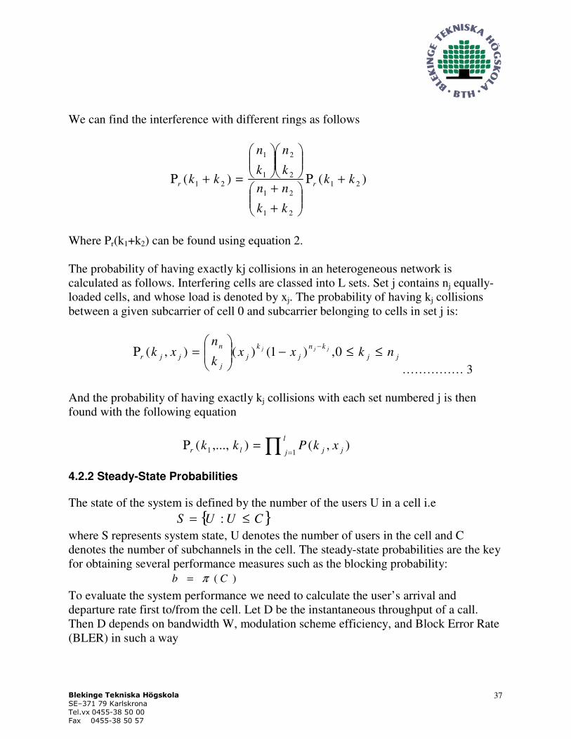
We can find the interference with different rings as follows
)()( 21
21
21
2
2
1
1
21 kk
kk
nn
k
n
k
n
kk rr +Ρ
+
+
=+Ρ
Where Pr(k1+k2) can be found using equation 2.
The probability of having exactly kj collisions in an heterogeneous network is
calculated as follows. Interfering cells are classed into L sets. Set j contains nj equally-
loaded cells, and whose load is denoted by xj. The probability of having kj collisions
between a given subcarrier of cell 0 and subcarrier belonging to cells in set j is:
jj
kn
j
k
j
j
n
jjr nkxxk
nxk jjj ≤≤−
=Ρ
−0,)1()(),(
…………… 3
And the probability of having exactly kj collisions with each set numbered j is then
found with the following equation
∏ ==Ρ
l
j jjlr xkPkk11 ),(),...,(
4.2.2 Steady-State Probabilities
The state of the system is defined by the number of the users U in a cell i.e
{ }CUUS ≤= :
where S represents system state, U denotes the number of users in the cell and C
denotes the number of subchannels in the cell. The steady-state probabilities are the key
for obtaining several performance measures such as the blocking probability:
)( Cb π=
To evaluate the system performance we need to calculate the user’s arrival and
departure rate first to/from the cell. Let D be the instantaneous throughput of a call.
Then D depends on bandwidth W, modulation scheme efficiency, and Block Error Rate
(BLER) in such a way

Blekinge Tekniska Högskola
SE–371 79 Karlskrona
Tel.vx 0455-38 50 00
Fax 0455-38 50 57
38
)1( BLEReWMD −×××= ............................ (4)
Where e is the efficiency of used modulation and, for example, equals to 1 bit per
symbol for QPSK 1/2 and to 5 for 64QAM 5/6. Modulation and coding rate are
selected based on experienced signal to interference plus noise ratio (SINR) in 3GPP
LTE, but a modulation scheme which provides BLER greater than 0.1 is selected.
Modulation efficiency can be obtained along with coding rate from the link level curves
provided in 3GPP TS 25.814, as shown in the figure 9 below.
0
20
40
60
80
100
120
0 5 10 15 20 25 30
Average received Es/N0 per receiver branch (dB)
Thro
ug
hput
(Mb
ps)
QRM-MLD using ASESS
MMSE
QPSK R = 1/2
QPSK R = 2/3
QPSK R = 3/416QAM R = 1/2
16QAM R = 2/3
16QAM R = 3/416QAM R = 4/564QAM R = 2/364QAM R = 3/4
64QAM R = 4/5
Figure 9: Link Level Simulation Curves [1]
The efficiency e and error rate BLER depends on the SINR, which is also written as
C/I. The product e x (1-BLER) can then be written as
)())(1()()1( ICBICBLERICeBLERe =−×=−×
where the last step is the definition of a function B.
Thus, the instantaneous throughput becomes
)()( ICBWMICD ××= ……………………............. (5)
SINR depends upon the following parameters
1- Propagation conditions
2- Distance between transmitter and receiver

Blekinge Tekniska Högskola
SE–371 79 Karlskrona
Tel.vx 0455-38 50 00
Fax 0455-38 50 57
39
3- The shadowing and
4- Frequency selective fading
Thus in OFDMA systems where a set of parallel, flat, and non-selective fading channels
are used, their transmission channels is only impacted by slow fading.
The SINR in the target cell is calculated as
( )∑ =
+
=n
i oNP
qP
I
C
1 D
i
i
0
qX
X
……………………………. (6)
where
Xi = 1 means there is a collision between a call in cell i and the user in target cell.
No is the background noise
qiD is the pathloss between the interfering base station i and the corresponding receiver
such as
1010
i
i
D
i rq
ξα
=
with ri the distance from base station in a cell i to the receiver in target cell.
iξ
a normal random variable due to shadowing, with zero mean and variance2ς and
[ ]4,2∈α is a constant.
4.2.2.1 Mean Service Time of a call
Mean Service Time of a call allocated one chunk (subchannel) is calculated using the
harmonic mean of throughput D when reuse of 1 is used:
[ ]−=D
ZET
……………….…………… (7)
1_
)()(
1
−
= ∑
X
r XPxD
D
...…………….. (8)

Blekinge Tekniska Högskola
SE–371 79 Karlskrona
Tel.vx 0455-38 50 00
Fax 0455-38 50 57
40
where D(x) is the throughput given the vector of collisions X:
1
))((
1..)(
−
=
XI
CB
EWMXDor
……….. (9)
Mean Service Time of a call in cell 0 is calculated as
( )[ ]( )
Β
Ε=ΤΕ=
XI
CWM
ZXT
or
1
.
_
Where
Z: Size of the file to be downloaded
M: Number of sub-channels assigned to a call
W: Channel bandwidth
Er0: Expectation over surface of cell 0
After finding mean service time of a call we can calculate steady-state probabilities i.e.
probability of having U calls in the system as follow
( )!
1
_
U
T
GU
U
=
λ
π ………………….. (10)
Where G, the normalizing constant, is found as
∑≤
=CU
U
U
T
G!
_
λ
Where λ = is the intensity of arriving calls (Poisson Process)
U = number of users (subscribers) in a cell
C = Subchannels in the cell
Steady-state probabilities are calculated using the departure rate in the target cell while
departure rate is calculated using the steady-state probabilities in the interfering cell.

Blekinge Tekniska Högskola
SE–371 79 Karlskrona
Tel.vx 0455-38 50 00
Fax 0455-38 50 57
41
So, an iterative approach is adopted to find steady-state probabilities as follow
1- Set the initial values for the iterations e.g. cell load = 0.5
2- Calculate )(UΠ
using these initial values and use the result to
calculate the load using equation (1)
3- Calculate the throughput equation (8)
4- Inject the new value of step 3 into equation (10) and repeat the process
until the values converge.
Equation (10) hold for any number of holding time thus the steady-state distribution
depends only on the mean-holding-time. Equation (10) is not effective for adaptive
resource assignment and instead the system is modeled as a simple birth-death (BD)
process whose solution is calculated taking into account the departure rate in each state,
as will be shown in section below.
The mean-time that a session spends in the system is calculated using the Little’s
formula:
[ ]
[ ] ∑ ∈=
−=
SUUUE
Where
b
UET
)(
)1(
π
λ
is the average number of calls in a cell.
4.3 Uplink Power Management
As the MS has limited battery power so its’ transmission power must be minimized as
much as possible but enough to achieve the required throughput. The minimal
transmission power Pe can be calculated with the help of the following procedure
i) Calculate SINR (Signal to Interference plus Noise Ratio) achievable when
signal is transmitted with maximum power Pmax
ii) Identify the MCS (Modulation and Coding Scheme) corresponding to above
calculated SINR
iii) Calculate the minimum transmission power Pe able to achieve above
identified MCS

Blekinge Tekniska Högskola
SE–371 79 Karlskrona
Tel.vx 0455-38 50 00
Fax 0455-38 50 57
42
Suppose there are X collisions in the target cell and the interference experienced by a
user in target cell because of a user in cell i is calculated as follows
)(
)),((),(
0 iU
iiiU
ii
U
i rq
rlPr
θθ =Ι
where
),(iii
rl θis the distance between base station and user in interfering cell
)),((iii
UrlP θ
is the mean transmit power of user in interfering cell at
distance l from the base station, and U
q0 is the pathloss between the user and basestation in the target cell.
The maximum achievable SINR by the target user is calculated as follows
01
00max
0max),(
)(),,,(
NrIX
rqPrXqSINR n
i iiUii
U
+=∑ =
θθ
where
Pmax is the maximal transmitted power of the target user
)(00
rqU
is the pathloss experienced by the target user at distance r0 from its base
station. Now we can identify MCS based on above calculated SINR with the help of
link level curves in figure 9 above.
To calculate the minimum transmittable power to achieve the above identified MCS, we
represent the modulation and coding scheme for SINR value s by the step functions
m(s) and c(s) respectively
∑=
×+
=
n
i
iiUii
erXqSINRcrXqSINRmS
NrlXrXqP
1 0max
0max
0
0))),,,(()),,,,(((
)),(.(),,,(
θθ
θθ
…..…13
where θ&r are distance vector and angle between interfering user and base station in
target cell.

Blekinge Tekniska Högskola
SE–371 79 Karlskrona
Tel.vx 0455-38 50 00
Fax 0455-38 50 57
43
S(m,c) is used to achieve the minimal SINR for the given modulation m and coding rate
c.
An average minimal transmittable power is required to account for changes in
interference, thus it is calculated as follows
[ ] )(),,,()( 0,0XPrXrPrP
rX
ere ∑ Ε= θθ
where Pr(X) is the collision probabilities of collision vector X and the transmitted
power is averaged over interfering cell surfaces.
4.4 Implementation
The tasks to be investigated in this thesis work include the comparison analysis of
different proposed frequency allocation schemes in the cell to minimize the intercell
interference and to investigate the resource allocation algorithm.
3GPP LTE is designed in bandwidth agnostic way i.e. bandwidth can be assigned in
any of 1.24, 2.5, 5, 10, 15, and 20 MHz to a user depending on channel condition and
availability. Radio resources are scheduled every 1ms. It is supposed that resources are
assigned on first come first serve basis in collaboration with the frequency allocation
schemes analysed in later sub-sections.
4.4.1 Simulation
As a full 3GPP LTE network or only link level simulator was not available for
performing this thesis work, the different frequency allocation schemes are investigated
using the above derived analytical calculations and graphs from a research work
performed earlier [16] are also considered.
4.4.2 Simulation Parameters
Different network parameters which are necessary for simulation are mentioned in this
sub-section. The parameters are considered for only one network cell but these may be
valid options for a full network.

Blekinge Tekniska Högskola
SE–371 79 Karlskrona
Tel.vx 0455-38 50 00
Fax 0455-38 50 57
44
4.4.2.1 Network Traffic
Two different types of network traffic are possible like real-time services such as voice
calls and other type if elastic services like downloading a file using FTP service.
As the main task of this thesis work is to compare frequency allocation schemes to
reduce inter-cell interference, only the elastic services are considered in this thesis
work. The real-time services like voice calls may consume less radio resources as the
voice is encoded into small packets which are transmitted quickly and frequently. These
services require a greater concern of QoS and error detection and recovery but these
services may have the same impact of frequency allocation schemes as on elastic-
services.
4.4.2.2 Modulation Schemes and Coding Rates
The available modulation schemes available in transmissions are QPSK, 16QAM, and
64QAM in the downlink and QPSK, 16QAM, and 64QAM as an option in the uplink.
The coding rate can be a value between 0 and 1.
The radio resources are assigned every 1ms. The modulation scheme and coding rate
are selected after every TTI based on the Signal to Noise plus Interference Ratio
(SINR).
Modulation scheme, coding rate, and resulting BLER are selected based on SINR with
the help of link level simulation curves given in figure 9 above. The upper limit on
BLER is 10%.
4.4.2.3 Channel Allocation
The total available bandwidth in a cell is 10MHz. Each subcarrier in 3GPP is of 15 KHz
bandwidth. The total bandwidth is divided into 30 subchannels of 20 subcarriers in each
subchannel thus having a bandwidth of 0.3MHz (15 KHz x 20).
4.4.2.4 User Generation
The user generation is considered to be a Poisson process where each user gets attached
with the network independently from other network users. They may stay in the
network until completion of file downloading. To keep calculations simple it is
assumed that each user is assigned exactly one sub-channel and the size of file being

Blekinge Tekniska Högskola
SE–371 79 Karlskrona
Tel.vx 0455-38 50 00
Fax 0455-38 50 57
45
downloaded is 4.5Mbytes so that the users may stay in the network for at least 2
minutes having assigned modulation of QPSK ½.
4.5 Performance Metrics
The performance of frequency allocation schemes is of course measured as how much
interference is reduced by deploying the particular scheme. Other performance metrics
include overall throughput, edge-user throughput, cell user blocking probability, and
cell capacity.

Blekinge Tekniska Högskola
SE–371 79 Karlskrona
Tel.vx 0455-38 50 00
Fax 0455-38 50 57
46

Blekinge Tekniska Högskola
SE–371 79 Karlskrona
Tel.vx 0455-38 50 00
Fax 0455-38 50 57
47
Chapter 5
5.0 Performance Analysis
Many probabilistic equations have been derived in chapter 4 which are being used in
this chapter to investigate the performance issues of different radio frequency allocation
schemes discussed in chapter 3. The plots shown in this chapter have been taken from
an IEEE research paper [16] for reference.
Generally the frequency allocation schemes can be categorized as static, semi-static,
and dynamic schemes. In the static schemes frequency allocation is planned and
assigned to cells before the network deployment which can not be changed afterward.
In the semi-static allocation schemes, the frequency allocation is performed after a long
period may be 10 days but dynamic allocations are performed repeatedly after a very
short period.
5.1 Intercell Interference Control Schemes
Performance of different ICIC schemes will be analysed in these subsections.
5.1.1 Static Interference Management with Reuse 1 and Reuse 3
The static schemes are useful in homogeneous network deployment where each cell has
the same load and similar channel allocation pattern. As mentioned in last chapter we
have 10 MHz of total bandwidth and we divide this into 30 subchannels of 20
subcarriers where each subchannel has a bandwidth of 0.3 MHz.
These 30 subchannels are divided into four parts. First part contains 18 subchannels in
it while other three parts have 4 subchannels in each. The cell centre users are assigned
subchannels from first part i.e. out of 18 subchannels while the cell edge users are
assigned the subchannels from one of the other three parts i.e. out of 4 subchannels.
Thus, there are only 18+4=22 subchannels available in the whole cell.
Cell center and edge users are identified with path loss. A threshold on path loss is set
in such a way that cell edge users may occupy 4/22 part of the surface area of the cell.
If we assume that only 1 subchannel is assigned to each user, we can conclude that we
are wasting a capacity by 8/30 i.e. we can handle only 22 users instead of 30 users.

Blekinge Tekniska Högskola
SE–371 79 Karlskrona
Tel.vx 0455-38 50 00
Fax 0455-38 50 57
48
Figure 5.1 – Cell Throughput
This figure 5.1 also includes graphs for partial isolation and full isolation which are
described later in this chapter.
As mentioned earlier the graphs displayed in this chapter have been extracted from a
research paper from IEEE [16] and are based on the probabilistic equations found in
chapter 4. In the figure 5.1, the graph displays throughput comparison of different static
frequency allocation schemes against the user’s arrival rate.
This graph also includes the comparison of reuse 1 and reuse 3. It is also of interest to
investigate whether the reuse 1 provides greater performance than that of reuse 3. We
can conclude from the graph that reuse 3 offers the worst throughput besides there is no
intercell interference but frequency resources are divided over three cells equally which
is of course a big waste of resources. Reuse 1 offer the greater throughput but inter-cell
interference comes as a disadvantage along with greater throughput advantage.
Ericsson’s proposal and Alcatel’s proposal, described in sections 3.1.1.1 and 3.1.1.2,
fall in the category of static-full isolation scheme.

Blekinge Tekniska Högskola
SE–371 79 Karlskrona
Tel.vx 0455-38 50 00
Fax 0455-38 50 57
49
The performance of Reuse 1 and static-full isolation are comparable as performance
degradation in reuse 1 scheme due to intercell interference is equated by the
performance degradation in static full isolation due to lesser radio resources available in
cell.
Figure 5.2 – Cell Throughput at Cell-Edge
Throughput in the cell edge is of greater interest than the cell centre throughput as cell
edge users have greater probability of suffering from intercell interference. Figure 5.2
shows that reuse 3 static full isolation scheme offers greater cell edge throughput than
the throughput achieved using the reuse 1. Thus a trade-off must be made between the
capacity and throughput at the cell edge in static frequency allocation schemes.
Figure 5.5 shows that reuse 3 has a larger blocking rate than the blocking rate in reuse
1. It can also be observed that the blocking rate of reuse 1 and static full isolation
schemes are comparable as user loss in reuse 1 due to interference is equated by less
resource availability in static full-isolation scheme.
5.1.2 Dynamic Interference Management Schemes
In this scheme, we assume a heterogeneous network where network cells have different
loads in them. We presume that the target cell i.e. cell 1 in the figure 5.3 has, say 50%,

Blekinge Tekniska Högskola
SE–371 79 Karlskrona
Tel.vx 0455-38 50 00
Fax 0455-38 50 57
50
more cell load than the load in its adjacent cells. This approach is more likely to be
realistic one. Radio resources are managed frequently.
As discussed earlier that the threshold on path loss is the distinguishing factor between
the cell centre users and cell edge users. The target cell decreases the path loss threshold
on an increase in the cell edge users while the adjoining cells increases the threshold on
path loss at the same time. Thus, there is lesser intercell interference in the cell edge
areas.
If suddenly, any of the adjoining cells receives more users in cell area then the same
procedure is repeated considering the adjoining cell as the target cell.
Figure 5.3- Network Deployment for Dynamic ICIC Scheme
We make a few assumptions while considering probabilistic equation derived in chapter
4. While calculating the steady-state probabilities derived in equation 10 in chapter 4
we assume that the adjoining interfering cells have the same load in them i.e. we
consider the adjoining network as a homogenous network.
After calculating the steady-state probability, it is used in equation 8 to calculate the
throughput D in the target cell.
Figure 5.4 shows the throughput analysis for both static and dynamic frequency
resource allocation schemes. Obviously, dynamic scheme outperforms the static scheme
as dynamic scheme handles more users or offers greater throughput even in the cell
edge area by maintaining the limit on path loss threshold which plays a very important
role in the reduction of intercell interference.
Figure 5.4 also points out that the dynamic scheme outperforms the static resource
allocation scheme in the adjoining areas for arrival rate above 0.8.
1
2
3
4 6
7
5

Blekinge Tekniska Högskola
SE–371 79 Karlskrona
Tel.vx 0455-38 50 00
Fax 0455-38 50 57
51
Dynamic resource allocation scheme is the good choice but a disadvantage of this
scheme is that it requires a lot of signaling on the continuous basis to maintain the limit
on path loss threshold. This may result in an obvious performance degradation and lot
of traffic generation between the eNodeBs of the 3GPP LTE cellular network.
Figure 5.4 – Cell throughput of both static & dynamic schemes
5.1.3 Partial Isolation Scheme
Partial isolation scheme falls in the category of semi-static resource allocation scheme.
In our deployment, we have 30 subchannels where each subchannel has 20 subcarriers
in it. In the static full isolation scheme each cell utilized 22 subchannels only where 18
subchannels have be assigned to be used in the cell center while only 4 subchannels are
allowed to be used in cell edge by setting up the threshold on path loss accordingly.
Partial isolation scheme utilizes all the available 30 subchannels in the cell but with
different configuration from reuse 1 scheme. This is achieved by controlling the
transmission power.
As in static full isolation scheme, 18 subchannels are available for the cell center users
where transmission can be made with its full power to achieve higher signal to noise
ratio at the receiver and only 4 subchannels are available in the cell edge area. When all

Blekinge Tekniska Högskola
SE–371 79 Karlskrona
Tel.vx 0455-38 50 00
Fax 0455-38 50 57
52
subchannels are assigned to users in the cell center area and more demand appears, it
can utilize the other 8 subchannels but with a strict restriction on its transmission power
i.e. the transmission power must be minimized enough that it do not cause increase in
inter-cell interference with the adjoining cells.
Figure 5.5 – Blocking rate for different frequency allocation schemes
This scheme offers greater utilization of radio resources than the static full isolation
scheme as all subchannels are utilized in the cell area. Of course, there is less capacity
handling and throughput in the cell edge area as only 4 out of 30 subchannels are
available in the cell edge. But this less resources availability is compensated by
introducing interference as minimum as possible. So, this scheme is preferable over
static full isolation scheme.
This scheme is also preferable over the dynamic allocation scheme described in section
5.2 as dynamic allocation schemes involve lot of signaling between the eNodeBs to
manage the resources in cell edge of target cell and its adjoining cell. This signaling is
an overhead which significantly reduces the overall system performance.
Figure 5.5 shows the partial isolation scheme significantly reduce the blocking rate by
providing more radio resources in the cell center so that more user can be served in the
target cell and also by reducing intercell interference probability.

Blekinge Tekniska Högskola
SE–371 79 Karlskrona
Tel.vx 0455-38 50 00
Fax 0455-38 50 57
53
5.2 Performance Analysis of Resources Scheduling Algorithms
Performance analysis of different radio resource scheduling scheme will be made here
in the following subsections.
5.2.1 Round Robin Scheme
In this scheme all resources are assigned to one user at a time and all other user have to
be in the waiting queue until their turn comes and the resources get free. As only one
user is served at a time thus the overall system performance will be degraded
considerably.
This scheme would have lowest rank in the scheduling algorithms list.
5.2.2 Algorithm based on Maximum Interference
There might be a lot of traffic classes and generally two classes are considered
including streaming class and real-time class. This scheduling scheme assigns the
resources based on the maximum interference suffered by a traffic channel and
irrespective of the class of the traffic and its need of the resources.
It also does not consider the position of the channel while scheduling resources for a
user. Thus, this scheme can not be considered as perfect scheduling algorithm for 3GPP
LTE.
5.2.3 Proportional Fairness Scheduling Algorithm
As all the users are prioritized first based on their requirement on the resources and its
channel condition, a fair scheduling can be expected from the algorithm which allocates
resources to the users according to their requirement and experienced channel
environment noise.
But, this scheme does not distinguish between the users based on their placement in the
cell while allocating the resources. This may be large performance degradation if we
intend to deploy the semi-static intercell interference co-ordination technique as
distinguishing the cell center user from the cell edge user is its basic requirement.
Thus, this resource scheduling algorithm can also not be suitable for 3GPP LTE.

Blekinge Tekniska Högskola
SE–371 79 Karlskrona
Tel.vx 0455-38 50 00
Fax 0455-38 50 57
54
5.2.4 Scheduling Algorithm based on Softer Frequency Reuse
This resource scheduling algorithm utilizes all the tasks performed in subsection 5.2.3
but additionally it also performs the probability calculations on the radio resources to
determine which resource can be assigned to the cell centre users and which resources
can be assigned to the cell edge users. In other words, this scheme is the same as the
scheme described in sub section 5.2.3 and additionally it counts the placement of the
user in the cell whom the resources are being assigned.
This scheme seems to be perfect i.e. it considers the user’s requirements on the radio
resources, the channel condition and also the location of the user in the target cell.
This scheme can be ideally utilized with semi-static intercell interference coordination
technique to achieve the best overall system performance.

Blekinge Tekniska Högskola
SE–371 79 Karlskrona
Tel.vx 0455-38 50 00
Fax 0455-38 50 57
55
Chapter 6
6.0 Conclusions
In this thesis work I have studied different frequency allocation schemes to mitigate
intercell interference. These schemes include the static, semi-static, and dynamic
schemes. These ICIC techniques have been examined from different aspects including
capacity, overall throughput, throughput at the cell edge, blocking rate, etc.
We noticed that each ICIC technique has its own merits and demerits but partial
isolation scheme which falls under the semi-static schemes is best suitable for 3GPP
LTE as it offers maximum capacity of the all schemes. It also offers higher overall
throughput, minimum blocking rate as maximum resources are made available for cell
centre users.
Different radio resource scheduling algorithms have also been studied in this thesis
work. These algorithms include round robin, algorithm based on maximum
interference, algorithm on proportional fairness, and algorithm based on softer
frequency reuse.
Radio resource scheduling scheme based on softer frequency reuse is likely to offer the
best performance compared to the other schemes discussed in this thesis work. This
thesis work considers all aspects while scheduling resources like the throughput needs
of the user, channel condition, available resources, and most importantly the location of
the user in the cell as it is the key factor of partial isolation intercell interference
coordination scheme discussed in chapter 5.

Blekinge Tekniska Högskola
SE–371 79 Karlskrona
Tel.vx 0455-38 50 00
Fax 0455-38 50 57
56
Chapter 7
7.0 Future work
As 3GPP LTE proposes that the radio resources should be scheduled every 1ms which
is also called TTI in scheduling, this will place a lot of processing on the eNodeBs. The
ways to speedup this scheduling process must be found.
3GPP LTE also offers the use of higher order modulation schemes like 64QAM which
will enhance the system throughput to a greater extent but it will also place a lot of
processing on both ends of transmission. Its behaviour should also be investigated.
Utilization of higher order modulation techniques may also suffer from the noise
created by the processing in both ends of the transmission. So, this noise behaviour
should also be investigated.
Blekinge Tekniska Högskola
SE–371 79 Karlskrona
Tel.vx 0455-38 50 00
Fax 0455-38 50 57
57
References
[1] 3GPP TSG RAN, TR 25.814, “Physical Layer Aspects for Evolved UTRA”,
V1.0.1, 2005-10-06
[2] An Inter-Cell Interference Coordination Technique Based on User’s Ratio and Multi-level
Frequency Allocations – F. Xiangning, C. Si, Z. Xiaodong – International Conference on
Wireless Communications, Networking and Mobile Computing, 2007 IEEE
[3] An Intercell Interference Cancellation Method for OFDM-Based Cellular Systems Using a Virtual
Smart Antenna – K.I. Lee, K.S. Woo, Y.H. Ko, J.Y. Ahn, Y.S. Cho –
Vehicular Technology Conference, 2006. VTC-2006 Fall. 2006 IEEE 64th
[4] Inter-cell Interference Coordination Based on Softer Frequency Reuse in OFDMA Cellular
Systems – X. Zhang, C. Hee, L. Jiang, J. Xu – IEEE Int. Conference Neural Networks - 2008
[5] Single Carrier FDMA for uplink wireless transmission - Hyung G, J. Lim, and David J. IEEE
Vehicular Technology Magazine | September 2006.
[6] OFDM Carrier Frequency Offset Estimation - Osesina, Yafan, Pagoti – MSc Thesis 2006.
Karlstad University
[7] Adaptive Radio Resource Management for VoIP and Data Traffic in 3GPP LTE Networks –
M.E.O. Lierida - M.Sc. Thesis, Mar 2008 – KTH
[8] Long Term Evolution (LTE): an introduction – White paper – Ericsson – 13 Dec. 08 : 17:00
http://www.ericsson.com/technology/whitepapers/lte_overview.pdf
[9] UTRA-UTRAN Long Term Evolution (LTE) and 3GPP System Architecture
Evolution (SAE) – 3GPP LTA Paper
ftp://ftp.3gpp.org/Inbox/2008_web_files/LTA_Paper.pdf
[10] Overview of the 3GPP Long Term Evolution Physical Layer
White Paper – J.Zyren, Dr. W. McCoy Technical Editor – Freescale Semiconductor
http://www.freescale.com/files/wireless_comm/doc/white_paper/3GPPEVOLUTIONWP.pdf
[11] 3GPP TS 36.302 v8.0.0 (2007-12) – Services provided by the physical layer Rel 8
[12] UMTS Long Term Evolution (LTE) Technology Introduction, Rhode&Schwarz – Dec 18, 23:00
http://www.3g4g.co.uk/Lte/Tutorials/RandS_WP_LTE.pdf
[13] Technical Overview of LTE – May 2008. H.G.Myung. Dec 18, 21:00
http://hgmyung.googlepages.com/3gppLTE.pdf
[14] 3GPP R1-050763, Ericsson, Muting – Further Discussion and Results, 2005-08-29, London

Blekinge Tekniska Högskola
SE–371 79 Karlskrona
Tel.vx 0455-38 50 00
Fax 0455-38 50 57
58
[15] An Inter-cell Interference Coordination Technique Based on User’s Ratio and Multi-Level
Frequency Allocations. Fan, Chen, Zhang – International Conference on Wireless
Communications, Networking and Mobile Computing, 2007, IEEE
[16] Performance Evaluation of Frequency Planning Schemes in OFDMA-based Networks -
Elayoubi, S.-E.; B. Haddada, O.; Fourestie, B. - IEEE Transactions on Wireless
Communications - May 2008.
[17] OFDM Basics – 07 Nov 2008 - http://tbhermawan.wordpress.com/2007/08/26/ofdm-basics/
[18] The Principles of OFDM by Louis Litwin & Michael Pugel - May 28, 2008. 12:09AM
http://rfdesign.com/images/archive/0101Puegel30.pdf
[19] The OFDM Challenge – By Jim Wight – 08 Nov 08, 1:30PM
http://www.commsdesign.com/story/OEG20011023S0040