dynamic behavior characterization of the milling tool …€”this paper is dedicated to the study...
TRANSCRIPT
Abstract—This paper is dedicated to the study of the milling
tool evolution on various major mechanics characteristics of the system workpiece–tool–material. The mechanical actions (forces and moments) measurement using a six-component dynamometer confirms the tool tip moments existence. The purpose of this paper is to highlight the dynamic evolution of the tooth mill cutter during the milling process. This research is necessary to knowledge of cutter tooth behavior in material cutting to easily feature separate the cutter teeth characteristics than other dynamics characteristics generated by the cutting process. In order to reach this objective, an experimental device designed to obtain dynamic information provided by the dynamic system machine/tool/chip/workpiece and to emphasize both mechanical actions (forces and moments) and vibrations synchronized with rotational speed.
Index Terms— dynamic, envelope, milling, torsor
I. INTRODUCTION
N current industrial market conditions based on increasing quality, reducing and increasing productivity thorough knowledge of dynamic phenomena generated by
the cutting process is absolute necessary. A number of works have been completed in time getting the results but further knowledge in the form of three-dimensional dynamic phenomena which taking place between tool/chip/workpiece remains a challenge that needs scientific resources. For a long time vibration analysis has been used for the detection and the identification of the machine tool's condition. Understanding and controlling these problems have led to many scientific researches, mainly focused on the instability of cutting process and in particular on the chatter milling vibration [1], [2]. Many scientifically research is to characterize the manufacturing system, in particular the spindle, the tool, the workpiece, to determine the
Manuscript received April 09, 2012; Revised April 16, 2012. This work
was supported by CNCSIS-UEFISCSU project PNII-RU, code 194/2010. C.F. Bisu is with the Machines and Production Systems of University
Politehnica of Bucharest, Spl. Independentei, no.313, 060042 Bucharest, Romania, (corresponding author: +40-72-401-6295; fax: +40-21-402-9724; e-mail: [email protected]).
R. Laheurte is with Materials Process Interactions, Institut of Mechanics and Engineering of Bordeaux,15 rue Naudet, Gradignan 33175, France (e-mail: [email protected]).
Ph. Darnis is with Materials Process Interactions, Institut of Mechanics and Engineering of Bordeaux,15 rue Naudet, Gradignan 33175, France (e-mail: [email protected]).
A. Gerard is with Materials Process Interactions, University Boradeaux and CNRS UMR 5469, 351 Cours de la Liberation, 33405 Talence, France (e-mail: [email protected]).
imperfections or the defects of functioning in order to improve the stiffness, the damping or manufacturing precision, [3], [4], [5], [6]. The methods used in monitoring techniques may be classified into two groups, direct and indirect methods. The direct methods are to measure the sizes of tool wear surface such as using optical sensors. The indirect methods are to measure the characteristics closely related with the state of tool wear, such as the cutting power and acoustic emission, [7], [8], [9]. However, due to the complexity of the machining process and the uncertainty in the correlation between the process parameters and tool wear, it is hard to obtain a satisfactory solution in tool wear monitoring, [10]. A large variety of sensors are used for measuring vibrations; piezoelectric transduction is the most common type in vibration sensing in machining operation [3]. Current dynamic milling models deal with the determination of optimal cutting conditions by vibration analysis and by dynamic forces analysis for one direction, two directions and three directions. This approach is not enough for a real dynamic modeling because the cutting process generates both forces and torques (moments). For instant these moments are not taken into account. The main purpose of this research is to develop a dynamic analysis closer to reality, which can answer in terms of processing requirements in three-dimensional dynamic conditions. A model which by integrating the moments generated by the cutting process, moments expressed in the tooth of tool. This approach will bring the necessary information for transferability from a known material by a new material [11], [12], [13]. So is desired to obtain a complete dynamic model which contains the expression and determination of both forces, and the resulting moments. This research is a part of a larger project of developing a dynamic three-dimensional cutting model by integrating the moments generated by cutting process [14]. Important results were obtained by an advanced analysis of vibration, spectral envelope analysis based on a Hilbert transform [15], to identify mechanical defects and obtaining a better response on the milling process quality [16]. In order to reach this objective, an experimental device designed to obtain dynamic information provided by the dynamic system machine/tool/chip/workpiece and to emphasize both mechanical actions (forces and moments) and vibrations synchronized with speed. This paper takes into account the dynamic evolution of the action of milling tool during cutting process. For the correct determination of the dynamic behavior of the mill cutter during the cutting process was adopted a mill cutter with a single tooth. In this case the impact tooth can be monitored and its evolution on a complete rotation of the tool.
Dynamic Behavior Characterization of the Milling Tool During the Cutting Process
Claudiu-Florinel BISU, Raynald LAHEURTE, Philippe DRANIS, Alain GERARD
I
Proceedings of the World Congress on Engineering 2012 Vol III WCE 2012, July 4 - 6, 2012, London, U.K.
ISBN: 978-988-19252-2-0 ISSN: 2078-0958 (Print); ISSN: 2078-0966 (Online)
WCE 2012
II. RESEARCH SCOPE
Monitoring and diagnostic condition of the cutting tool in the machining process is very important since tool condition will affect the mechanical elements of the machine tool, quality process and unexpected failure: tool and workpiece damages [3], [6]. A successful diagnostic and monitoring solution depends on the ability of the system to identify process abnormalities and respond in critical time with the appropriate feedback actions [4], [5], [10]. The purpose of this paper is to highlight the dynamic evolution of the tooth mill cutter during the milling process. This research is necessary to deepen knowledge of cutter tooth behavior in material cutting so you can easily feature separate the cutter teeth characteristics than other dynamics characteristics generated by the cutting process. Results of these experiments are injected into the optimization algorithm based on the envelope method developed for monitoring the milling process. Research on vibration analysis of rotating elements is developed monitoring techniques by the methods of envelope to detect defects on bearings or gears. The transposition of these methods adapted to the field of machining combined with resampling techniques and signal processing by applying FFT synchronous and Hilbert transform has demonstrated very promising results [16].
III. EXPERIMENTAL SETUP
An experimental protocol was designed and developed for the acquisition, processing and analyzing of the three-dimensional vibration and mechanical actions signal provided by the system: machine/tool/chip/workpiece, fig1. The experiments were performed on a five axes CNC horizontal machining center, were the torsor measurement (3 components of forces and 3 components of moments) was performed using 6- components dynamometer QZZ2 [6].
Fig. 1. Experimental device
IV. DYNAMIC MILLING TOOL EVOLUTION
Dynamic behavior is received through PCB three-axial piezoelectric accelerometer fixed on the workpiece and a PCB unidirectional piezoelectric accelerometer placed on the spindle in the radial direction. The speed rotational for the tool is obtained by a laser sensor. To accomplish the objectives of this research a QZZ2 dynamometer [17] is
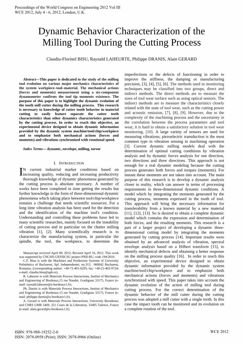
used to measure simultaneously 6 components (forces and moments according to each direction) in the same time with vibrations signals and tool position, fig2. The cutting tool chosen with 63 mm diameter is a tool cutter with a SEMN 120308T insert. The tests were performed both in X and Y direction with 120 m/min cutting speed and 0.1 mm/tooth. The signals were recorded with 25000 samples/sec, 32768 samples buffer size and a 10000 samples block size.
Fig. 2. Milling test configuration
A. Mechanical actions torsor characterization
The main aim of the reported research is to investigate the possibility to assess the workpiece surface quality in milling by use the tool dynamic evaluation. Correlation between the output signals (cutting forces, vibration) and the type of features which appeared on the workpiece surface were investigated by use of time and frequency analysis of the output signals [16], [18]. In order to analyze the quality monitoring tool during the cutting process is carried out an analysis of the mechanical action of the forces and moments generated by the torque tool/ chip/workpiece. Thus for the above cutting conditions is obtained the evolution of forces (Fx, Fy, Fz) and moments (Mx, My, Mz) in amplitude type pick to pick, fig3 and fig4.
),,( ZYXOO
workpiecetoolrdynamometeM
R
(1)
),,( ZYX
OPP
workpiecetoolrdynamometeROPMM
R
(2)
With the real-time data provided by the position transducers, the instant positions on the three linear axes and the angular position in the center of the tool are known. Starting at this position, tooth tip position is determinate. By measuring forces and moments in the center of dynamometer (1) with the tool position identification determine the moments of the tool tip (2). Dynamic behavior of the milling process is highlight by the waveform signal torsor measured in center of the dynamometer and transported to the tooth tip of the milling cutter. The forces and moments of the torsor are presented in the overall shape, for trend identification and amplitude information, in fig3 and fig4. Correlation between the output signals cutting forces, moments and vibration using a several processing techniques give the necessary information on the correct identification of the tooth during the cutting process.
Proceedings of the World Congress on Engineering 2012 Vol III WCE 2012, July 4 - 6, 2012, London, U.K.
ISBN: 978-988-19252-2-0 ISSN: 2078-0958 (Print); ISSN: 2078-0966 (Online)
WCE 2012
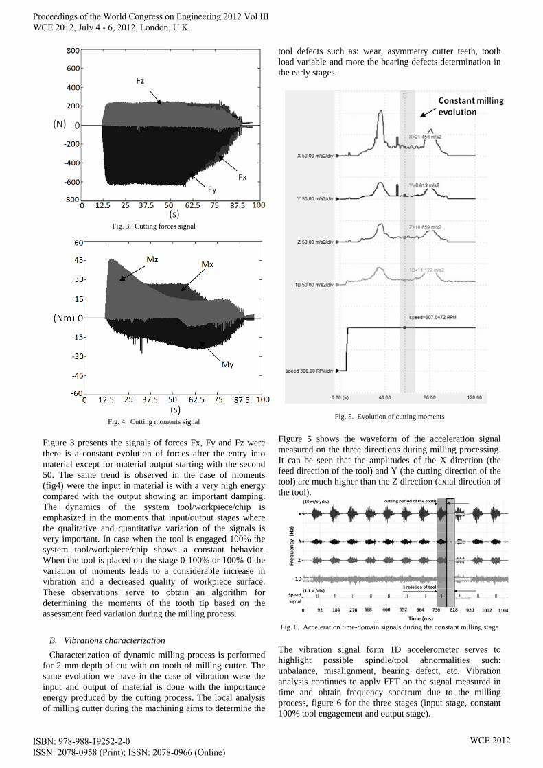
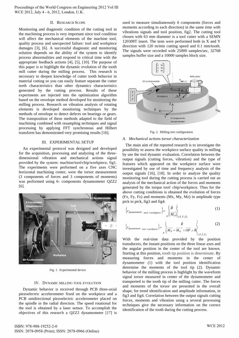
Fig. 3. Cutting forces signal
Fig. 4. Cutting moments signal
Figure 3 presents the signals of forces Fx, Fy and Fz were there is a constant evolution of forces after the entry into material except for material output starting with the second 50. The same trend is observed in the case of moments (fig4) were the input in material is with a very high energy compared with the output showing an important damping. The dynamics of the system tool/workpiece/chip is emphasized in the moments that input/output stages where the qualitative and quantitative variation of the signals is very important. In case when the tool is engaged 100% the system tool/workpiece/chip shows a constant behavior. When the tool is placed on the stage 0-100% or 100%-0 the variation of moments leads to a considerable increase in vibration and a decreased quality of workpiece surface. These observations serve to obtain an algorithm for determining the moments of the tooth tip based on the assessment feed variation during the milling process.
B. Vibrations characterization
Characterization of dynamic milling process is performed for 2 mm depth of cut with on tooth of milling cutter. The same evolution we have in the case of vibration were the input and output of material is done with the importance energy produced by the cutting process. The local analysis of milling cutter during the machining aims to determine the
tool defects such as: wear, asymmetry cutter teeth, tooth load variable and more the bearing defects determination in the early stages.
Fig. 5. Evolution of cutting moments
Figure 5 shows the waveform of the acceleration signal measured on the three directions during milling processing. It can be seen that the amplitudes of the X direction (the feed direction of the tool) and Y (the cutting direction of the tool) are much higher than the Z direction (axial direction of the tool).
Fig. 6. Acceleration time-domain signals during the constant milling stage
The vibration signal form 1D accelerometer serves to highlight possible spindle/tool abnormalities such: unbalance, misalignment, bearing defect, etc. Vibration analysis continues to apply FFT on the signal measured in time and obtain frequency spectrum due to the milling process, figure 6 for the three stages (input stage, constant 100% tool engagement and output stage).
Proceedings of the World Congress on Engineering 2012 Vol III WCE 2012, July 4 - 6, 2012, London, U.K.
ISBN: 978-988-19252-2-0 ISSN: 2078-0958 (Print); ISSN: 2078-0966 (Online)
WCE 2012
C. Milling cutter tooth frequency
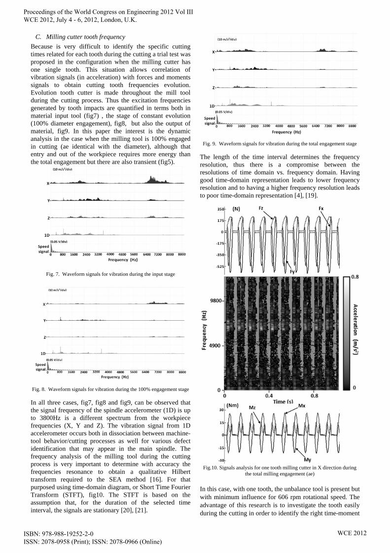
Because is very difficult to identify the specific cutting times related for each tooth during the cutting a trial test was proposed in the configuration when the milling cutter has one single tooth. This situation allows correlation of vibration signals (in acceleration) with forces and moments signals to obtain cutting tooth frequencies evolution. Evolution tooth cutter is made throughout the mill tool during the cutting process. Thus the excitation frequencies generated by tooth impacts are quantified in terms both in material input tool (fig7) , the stage of constant evolution (100% diameter engagement), fig8, but also the output of material, fig9. In this paper the interest is the dynamic analysis in the case when the milling tool is 100% engaged in cutting (ae identical with the diameter), although that entry and out of the workpiece requires more energy than the total engagement but there are also transient (fig5).
Fig. 7. Waveform signals for vibration during the input stage
Fig. 8. Waveform signals for vibration during the 100% engagement stage
In all three cases, fig7, fig8 and fig9, can be observed that the signal frequency of the spindle accelerometer (1D) is up to 3800Hz is a different spectrum from the workpiece frequencies (X, Y and Z). The vibration signal from 1D accelerometer occurs both in dissociation between machine-tool behavior/cutting processes as well for various defect identification that may appear in the main spindle. The frequency analysis of the milling tool during the cutting process is very important to determine with accuracy the frequencies resonance to obtain a qualitative Hilbert transform required to the SEA method [16]. For that purposed using time-domain diagram, or Short Time Fourier Transform (STFT), fig10. The STFT is based on the assumption that, for the duration of the selected time interval, the signals are stationary [20], [21].
Fig. 9. Waveform signals for vibration during the total engagement stage
The length of the time interval determines the frequency resolution, thus there is a compromise between the resolutions of time domain vs. frequency domain. Having good time-domain representation leads to lower frequency resolution and to having a higher frequency resolution leads to poor time-domain representation [4], [19].
Fig.10. Signals analysis for one tooth milling cutter in X direction during
the total milling engagement (ae)
In this case, with one tooth, the unbalance tool is present but with minimum influence for 606 rpm rotational speed. The advantage of this research is to investigate the tooth easily during the cutting in order to identify the right time-moment
Proceedings of the World Congress on Engineering 2012 Vol III WCE 2012, July 4 - 6, 2012, London, U.K.
ISBN: 978-988-19252-2-0 ISSN: 2078-0958 (Print); ISSN: 2078-0966 (Online)
WCE 2012
of entrance/exit workpiece. The frequency resonance domain identified in the fig10 is 6500 – 7800 Hz, can be observed in fig7, fig8 and fig9. Knowing the frequency excitation for the tooth during the milling process is an important progress for monitoring and diagnostic analysis.
A. Milling cutter teeth evolution
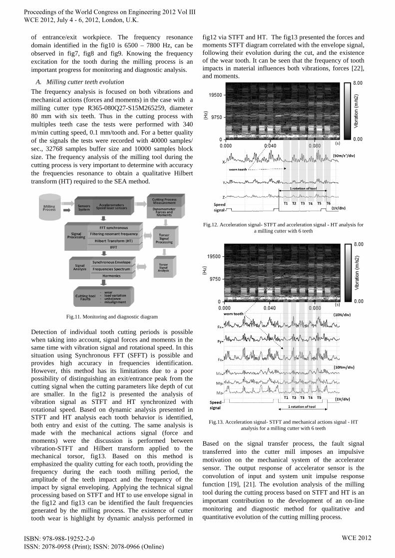
The frequency analysis is focused on both vibrations and mechanical actions (forces and moments) in the case with a milling cutter type R365-080Q27-S15M265259, diameter 80 mm with six teeth. Thus in the cutting process with multiples teeth case the tests were performed with 340 m/min cutting speed, 0.1 mm/tooth and. For a better quality of the signals the tests were recorded with 40000 samples/ sec., 32768 samples buffer size and 10000 samples block size. The frequency analysis of the milling tool during the cutting process is very important to determine with accuracy the frequencies resonance to obtain a qualitative Hilbert transform (HT) required to the SEA method.
Fig.11. Monitoring and diagnostic diagram
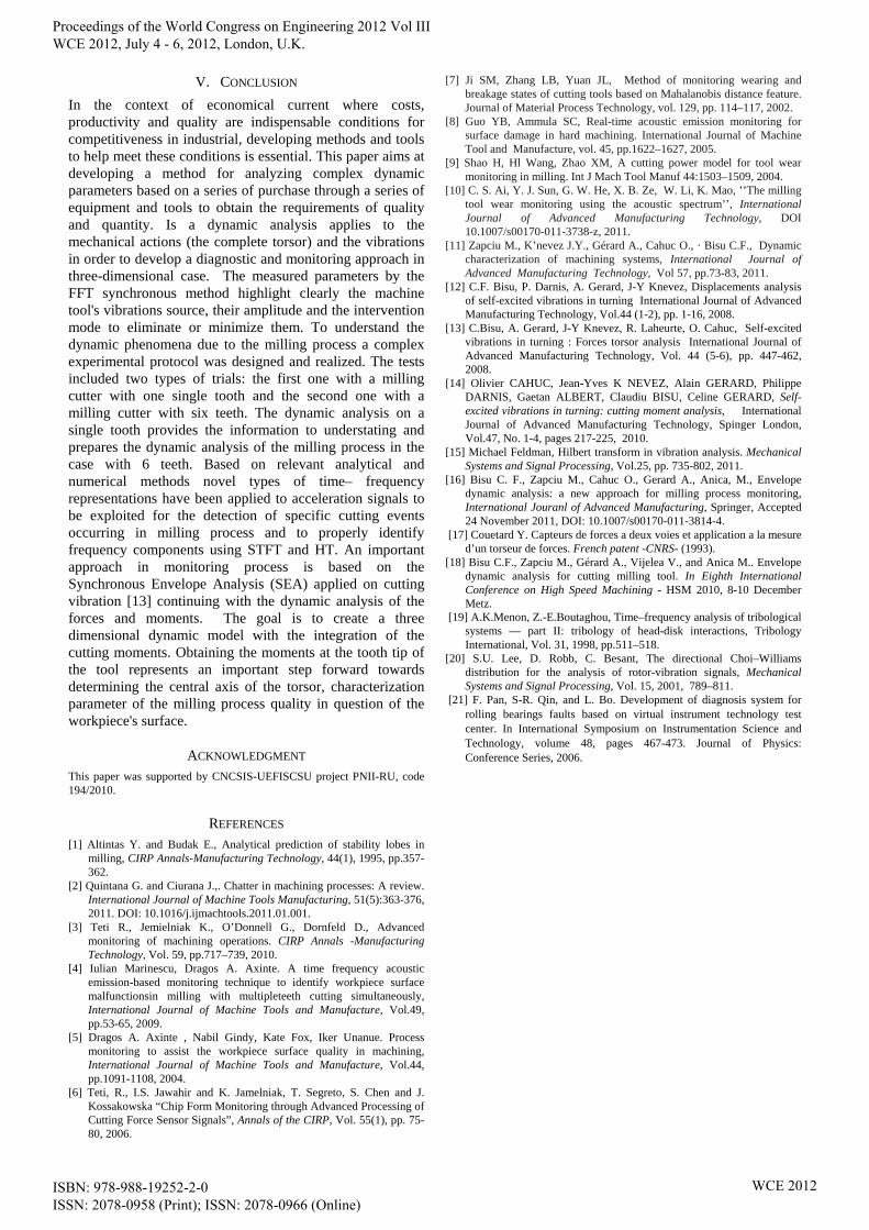
Detection of individual tooth cutting periods is possible when taking into account, signal forces and moments in the same time with vibration signal and rotational speed. In this situation using Synchronous FFT (SFFT) is possible and provides high accuracy in frequencies identification. However, this method has its limitations due to a poor possibility of distinguishing an exit/entrance peak from the cutting signal when the cutting parameters like depth of cut are smaller. In the fig12 is presented the analysis of vibration signal as STFT and HT synchronized with rotational speed. Based on dynamic analysis presented in STFT and HT analysis each tooth behavior is identified, both entry and exist of the cutting. The same analysis is made with the mechanical actions signal (force and moments) were the discussion is performed between vibration-STFT and Hilbert transform applied to the mechanical torsor, fig13. Based on this method is emphasized the quality cutting for each tooth, providing the frequency during the each tooth milling period, the amplitude of the teeth impact and the frequency of the impact by signal enveloping. Applying the technical signal processing based on STFT and HT to use envelope signal in the fig12 and fig13 can be identified the fault frequencies generated by the milling process. The existence of cutter tooth wear is highlight by dynamic analysis performed in
fig12 via STFT and HT. The fig13 presented the forces and moments STFT diagram correlated with the envelope signal, following their evolution during the cut, and the existence of the wear tooth. It can be seen that the frequency of tooth impacts in material influences both vibrations, forces [22], and moments.
Fig.12. Acceleration signal- STFT and acceleration signal - HT analysis for
a milling cutter with 6 teeth
Fig.13. Acceleration signal- STFT and mechanical actions signal - HT analysis for a milling cutter with 6 teeth
Based on the signal transfer process, the fault signal transferred into the cutter mill imposes an impulsive motivation on the mechanical system of the accelerator sensor. The output response of accelerator sensor is the convolution of input and system unit impulse response function [19], [21]. The evolution analysis of the milling tool during the cutting process based on STFT and HT is an important contribution to the development of an on-line monitoring and diagnostic method for qualitative and quantitative evolution of the cutting milling process.
Proceedings of the World Congress on Engineering 2012 Vol III WCE 2012, July 4 - 6, 2012, London, U.K.
ISBN: 978-988-19252-2-0 ISSN: 2078-0958 (Print); ISSN: 2078-0966 (Online)
WCE 2012
V. CONCLUSION
In the context of economical current where costs, productivity and quality are indispensable conditions for competitiveness in industrial, developing methods and tools to help meet these conditions is essential. This paper aims at developing a method for analyzing complex dynamic parameters based on a series of purchase through a series of equipment and tools to obtain the requirements of quality and quantity. Is a dynamic analysis applies to the mechanical actions (the complete torsor) and the vibrations in order to develop a diagnostic and monitoring approach in three-dimensional case. The measured parameters by the FFT synchronous method highlight clearly the machine tool's vibrations source, their amplitude and the intervention mode to eliminate or minimize them. To understand the dynamic phenomena due to the milling process a complex experimental protocol was designed and realized. The tests included two types of trials: the first one with a milling cutter with one single tooth and the second one with a milling cutter with six teeth. The dynamic analysis on a single tooth provides the information to understating and prepares the dynamic analysis of the milling process in the case with 6 teeth. Based on relevant analytical and numerical methods novel types of time– frequency representations have been applied to acceleration signals to be exploited for the detection of specific cutting events occurring in milling process and to properly identify frequency components using STFT and HT. An important approach in monitoring process is based on the Synchronous Envelope Analysis (SEA) applied on cutting vibration [13] continuing with the dynamic analysis of the forces and moments. The goal is to create a three dimensional dynamic model with the integration of the cutting moments. Obtaining the moments at the tooth tip of the tool represents an important step forward towards determining the central axis of the torsor, characterization parameter of the milling process quality in question of the workpiece's surface.
ACKNOWLEDGMENT This paper was supported by CNCSIS-UEFISCSU project PNII-RU, code 194/2010.
REFERENCES [1] Altintas Y. and Budak E., Analytical prediction of stability lobes in
milling, CIRP Annals-Manufacturing Technology, 44(1), 1995, pp.357-362.
[2] Quintana G. and Ciurana J.,. Chatter in machining processes: A review. International Journal of Machine Tools Manufacturing, 51(5):363-376, 2011. DOI: 10.1016/j.ijmachtools.2011.01.001.
[3] Teti R., Jemielniak K., O’Donnell G., Dornfeld D., Advanced monitoring of machining operations. CIRP Annals -Manufacturing Technology, Vol. 59, pp.717–739, 2010.
[4] Iulian Marinescu, Dragos A. Axinte. A time frequency acoustic emission-based monitoring technique to identify workpiece surface malfunctionsin milling with multipleteeth cutting simultaneously, International Journal of Machine Tools and Manufacture, Vol.49, pp.53-65, 2009.
[5] Dragos A. Axinte , Nabil Gindy, Kate Fox, Iker Unanue. Process monitoring to assist the workpiece surface quality in machining, International Journal of Machine Tools and Manufacture, Vol.44, pp.1091-1108, 2004.
[6] Teti, R., I.S. Jawahir and K. Jamelniak, T. Segreto, S. Chen and J. Kossakowska “Chip Form Monitoring through Advanced Processing of Cutting Force Sensor Signals”, Annals of the CIRP, Vol. 55(1), pp. 75-80, 2006.
[7] Ji SM, Zhang LB, Yuan JL, Method of monitoring wearing and breakage states of cutting tools based on Mahalanobis distance feature. Journal of Material Process Technology, vol. 129, pp. 114–117, 2002.
[8] Guo YB, Ammula SC, Real-time acoustic emission monitoring for surface damage in hard machining. International Journal of Machine Tool and Manufacture, vol. 45, pp.1622–1627, 2005.
[9] Shao H, Hl Wang, Zhao XM, A cutting power model for tool wear monitoring in milling. Int J Mach Tool Manuf 44:1503–1509, 2004.
[10] C. S. Ai, Y. J. Sun, G. W. He, X. B. Ze, W. Li, K. Mao, ’’The milling tool wear monitoring using the acoustic spectrum’’, International Journal of Advanced Manufacturing Technology, DOI 10.1007/s00170-011-3738-z, 2011.
[11] Zapciu M., K’nevez J.Y., Gérard A., Cahuc O., · Bisu C.F., Dynamic characterization of machining systems, International Journal of Advanced Manufacturing Technology, Vol 57, pp.73-83, 2011.
[12] C.F. Bisu, P. Darnis, A. Gerard, J-Y Knevez, Displacements analysis of self-excited vibrations in turning International Journal of Advanced Manufacturing Technology, Vol.44 (1-2), pp. 1-16, 2008.
[13] C.Bisu, A. Gerard, J-Y Knevez, R. Laheurte, O. Cahuc, Self-excited vibrations in turning : Forces torsor analysis International Journal of Advanced Manufacturing Technology, Vol. 44 (5-6), pp. 447-462, 2008.
[14] Olivier CAHUC, Jean-Yves K NEVEZ, Alain GERARD, Philippe DARNIS, Gaetan ALBERT, Claudiu BISU, Celine GERARD, Self-excited vibrations in turning: cutting moment analysis, International Journal of Advanced Manufacturing Technology, Spinger London, Vol.47, No. 1-4, pages 217-225, 2010.
[15] Michael Feldman, Hilbert transform in vibration analysis. Mechanical Systems and Signal Processing, Vol.25, pp. 735-802, 2011.
[16] Bisu C. F., Zapciu M., Cahuc O., Gerard A., Anica, M., Envelope dynamic analysis: a new approach for milling process monitoring, International Jouranl of Advanced Manufacturing, Springer, Accepted 24 November 2011, DOI: 10.1007/s00170-011-3814-4.
[17] Couetard Y. Capteurs de forces a deux voies et application a la mesure d’un torseur de forces. French patent -CNRS- (1993).
[18] Bisu C.F., Zapciu M., Gérard A., Vijelea V., and Anica M.. Envelope dynamic analysis for cutting milling tool. In Eighth International Conference on High Speed Machining - HSM 2010, 8-10 December Metz.
[19] A.K.Menon, Z.-E.Boutaghou, Time–frequency analysis of tribological systems — part II: tribology of head-disk interactions, Tribology International, Vol. 31, 1998, pp.511–518.
[20] S.U. Lee, D. Robb, C. Besant, The directional Choi–Williams distribution for the analysis of rotor-vibration signals, Mechanical Systems and Signal Processing, Vol. 15, 2001, 789–811.
[21] F. Pan, S-R. Qin, and L. Bo. Development of diagnosis system for rolling bearings faults based on virtual instrument technology test center. In International Symposium on Instrumentation Science and Technology, volume 48, pages 467-473. Journal of Physics: Conference Series, 2006.
Proceedings of the World Congress on Engineering 2012 Vol III WCE 2012, July 4 - 6, 2012, London, U.K.
ISBN: 978-988-19252-2-0 ISSN: 2078-0958 (Print); ISSN: 2078-0966 (Online)
WCE 2012