dynamic and static stability assessment of rock slopes ... · dynamic and static stability...
TRANSCRIPT

Rock Mech. Rock Engng. (2000) 33 (1), 31±51Rock Mechanicsand Rock Engineering
: Springer-Verlag 2000Printed in Austria
Dynamic and Static Stability Assessment of Rock SlopesAgainst Wedge Failures
By
H. Kumsar1, OÈ . Aydan2, and R. Ulusay3
1 Pamukkale University, Department of Geological Engineering, Kinikli Campus, Denizli,Turkey
2 Tokai University, Department of Marine Civil Engineering, Orido, Shimizu, Japan3 Hacettepe University, Department of Geological Engineering, Ankara, Turkey
Summary
The stability of slopes during and after excavation is always of great concern in the ®eld ofrock engineering. One of the structurally controlled modes of failure in jointed rock slopesis wedge failure. The limiting equilibrium methods for slopes under various conditionsagainst wedge failure have been previously proposed by several investigators. However,these methods do not involve dynamic assessments and have not yet been validated byexperimental results. In this paper, the tests performed on model wedges under static anddynamic loading conditions are described and the existing limiting equilibrium methods areextended to take into account dynamic e¨ects. The applicability and validity of the pre-sented method are checked through model tests carried out under well controlled conditionsand by actual cases studied by the authors, both in Turkey and Japan.
1. Introduction
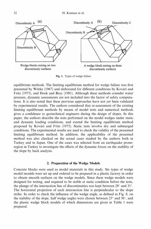
One of the fundamental problems of engineering geology and geotechnical engi-neering is assessing and maintaining the stability of natural and man-made slopes.Usually natural slopes are stable when they are not disturbed by any externalforce, such as seismic and hydrostatic forces, blasting and surcharge loading.When slopes are excavated for highways, power plants, construction of buildingsand open pit mining, they may become unstable. In these situations, stabilityassessments become crucial for the stability of engineering work and for economy.In competent rocks, the stability of many slopes is controlled by wedges (Fig. 1aand 1b) or slabs of intact rock bounded by weak discontinuities, usually joints,faults or shear zones. Attitude of discontinuities in relation to the slope face ori-entation determines the kinematic feasibility. The geometrical intersection of thediscontinuity sets with each other and the orientation of the slope face leads todi¨erent types of structurally controlled slope instability.
Wedge failures are analysed using kinematical approaches and also limiting
equilibrium methods. The limiting equilibrium method for wedge failure was ®rstpresented by Wittke (1967) and elaborated for di¨erent conditions by KovaÂri andFritz (1975), and Hoek and Bray (1981). Although these methods consider waterpressure, dynamic assessments are not included into the factor of safety computa-tions. It is also noted that these previous approaches have not yet been validatedby experimental results. The authors considered that re-assessment of the existinglimiting equilibrium methods by means of model tests and numerical methodsgives a con®dence to geotechnical engineers during the design of slopes. In thispaper, the authors describe the tests performed on the model wedges under staticand dynamic loading conditions, and extend the limiting equilibrium methodproposed by KovaÂri and Fritz (1975). Static tests involve dry and submergedconditions. The experimental results are used to check the validity of the presentedlimiting equilibrium method. In addition, the applicability of the presentedmethod was also checked on the actual cases studied by the authors both inTurkey and in Japan. One of the cases was selected from an earthquake prone-region in Turkey to investigate the e¨ects of the dynamic forces on the stability ofthe slope by back analysis.
2. Preparation of the Wedge Models
Concrete blocks were used as model materials in this study. Six types of wedgemodel moulds were set up and ordered to be prepared in a plastic factory in orderto obtain smooth surfaces on the wedge models. Since these wedge models weredesigned for testing, and required to be stable at static condition before the tests,the plunge of the intersection line of discontinuities was kept between 28� and 31�.The horizontal projection of each intersection line is perpendicular to the slopestrike. In order to check the in¯uence of the wedge angle, as de®ned in Fig. 8, onthe stability of the slope, half wedge angles were chosen between 23� and 56�, andthe plastic wedge block models of which dimensions are given in Table 1 wereprepared.
Fig. 1. Types of wedge failure
32 H. Kumsar et al.
Base and wedge models were formed by using mortar, whose geomechanicalparameters are similar to those of rocks. The composition of the mortar used forthe preparation of the models includes 17.5 kN of ®ne sand, 3.5 kN of cement and1.75 kN of water.
In order to model the wedge base and wedge blocks, wooden boxes with alength of 28 cm, a width of 14 cm and a depth of 12 cm were used. The prepara-tion of the concrete models was carried out in two stages consisting of base andwedge model preparations. Base model preparation requires forming two discon-tinuity surfaces, that make a wedge failure surface, and the space for the wedgeblock volume. This was done by attaching specially prepared plastic wedge blockshaving smooth surfaces and sharp edges at the sides of the boxes.
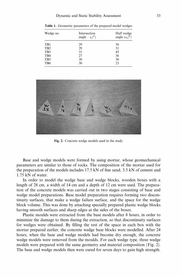
Plastic moulds were extracted from the base models after 8 hours, in order tominimize the damage to them during the extraction, so that discontinuity surfacesfor wedges were obtained. By ®lling the rest of the space in each box with themortar prepared earlier, the concrete wedge base blocks were modelled. After 24hours, when the base and wedge models had become dry enough, the concretewedge models were removed from the moulds. For each wedge type, three wedgemodels were prepared with the same geometry and material composition (Fig. 2).The base and wedge models then were cured for seven days to gain high strength.
Table 1. Geometric parameters of the prepared model wedges
Wedge no. Intersectionangle ± ia�0�
Half wedgeangle oa�0�
TB1 29 56TB2 29 51TB3 31 45TB4 27 36TB5 30 30TB6 30 23
Fig. 2. Concrete wedge models used in the study
Dynamic and Static Stability Assessment 33
3. Model Tests
A model testing program was undertaken to check the validity of the limitingequilibrium method to be presented in the next section. The concrete wedge mod-els were tested under dynamic and static conditions. The static tests were carriedout by considering dry and submerged conditions. The tests were brie¯y describedin the following sections.
3.1 Static Tests
The friction angle between the concrete base block and the wedge models wasdetermined from a tilting test, using a portable tilting device. Two concrete blocks,each having the same composition with the base and wedge models, were put oneach other and the tilting angle at which the upper block slides on the lower blockis assumed as the friction angle (f � 35�), mobilised along the discontinuities.
3.1.1 Dry Tests
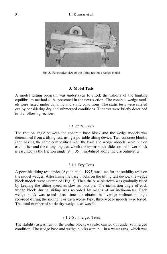
A portable tilting test device (Aydan et al., 1995) was used for the stability tests onthe model wedges. After ®xing the base blocks on the tilting test device, the wedgeblock models were assembled (Fig. 3). Then the base platform was gradually tiltedby keeping the tilting speed as slow as possible. The inclination angle of eachwedge block during sliding was recorded by means of an inclinometer. Eachwedge block was tested three times to obtain the average inclination anglerecorded during the sliding. For each wedge type, three wedge models were tested.The total number of static-dry wedge tests was 54.
3.1.2 Submerged Tests
The stability assessment of the wedge blocks was also carried out under submergedcondition. The wedge base and wedge blocks were put in a water tank, which was
Fig. 3. Perspective view of the tilting test on a wedge model
34 H. Kumsar et al.

®lled with water up to a level at which all the model blocks were fully submerged(Fig. 4). The tilting test device was again used to measure the inclination angle ofthe base of the wedge models under submerged condition. Each wedge model wastested three times. For each wedge type, three concrete wedge models were testedand the average of the inclination angles at failure was assumed as a critical failureinclination angle for each wedge model.
3.2 Dynamic Tests
Rock slope failures may also occur under the in¯uence of tectonic events in aregion. Heavily jointed rock slopes may indicate that the region was subjected toactive tectonic events in the past. If the tectonic events still continue from time totime, the slopes will be subjected to seismic forces. Even an engineering structuremay not fail because of an earthquake shock; it may collapse as a result of a largescale wedge failure which is caused by the same earthquake shock. Dynamic forcescan also result from blasting, tra½c and machinery work near slopes. The in¯u-ence of the seismic forces decreases the slope stability. Therefore, it is also an im-portant task to investigate the dynamic stability of slopes.
Dynamic testing of the wedge models were performed in the laboratory bymeans of a one-dimensional shaking table, which moves along horizontal plane.The wave forms of the shaking table are sinusoidal, saw tooth, rectangular, tra-pezoidal and triangle. The shaking table has a square shape with 1m side length.The frequency of the wave to be applicable to the shaking table can range between1 Hz and 50 Hz. The table has a maximum stroke of 100 mm, a maximum accel-eration of 6 m/s2 and a maximum load of 980.7 N.
Each wedge base block was ®xed on the shaking table to receive same shakingwith the shaking table during the dynamic test. The accelerations acting on the
Fig. 4. Front view of the submerged stability test of a wedge model
Dynamic and Static Stability Assessment 35

shaking table, the base and wedge blocks were recorded during the experiment,and saved on a data ®le as digital data (Fig. 5). The reason for recording accele-rations at three di¨erent locations during the experiments is to determine the ac-celeration at the moment of failure as well as any ampli®cations from the base tothe top of the block. In fact, when the amplitude of input acceleration wave isincreased, there must be a sudden decrease on the wedge block accelerationrecords during the wedge failure, while the others should be increasing.
The accelerographs may not completely record the acceleration data due totheir insu½cient sampling time of a record. Therefore, incomplete records maylead the investigator to misinterpret the acceleration at the time of failure. In Fig.6 the acceleration records of shaking table, base and wedge blocks are shown forthe dynamic stability test on the model numbered as TB1, as mentioned in Table1. The wedge block failed just after 9th second, as indicated in Fig. 6. The accel-eration peaks of the shaking table and base blocks were incomplete at the momentof failure due to insu½cient sampling time of the record. Finally, the failuremoment is detected and the acceleration during failure is obtained by comparingthe acceleration record graphs drawn for the shaking table, the base and the wedgeblocks.
4. Limit Equilibrium Method
The approach proposed by KovaÂri and Fritz (1975) for the analysis of wedgefailures is used and modi®ed to take into account the possible loading conditionsconsidered herein. The forces acting on a wedge block can be illustrated as shownin Fig. 7. If the force equilibrium in the directions of s, n and t is considered, thefollowing equations are obtained.
Fig. 5. A close up view from the shaking table during the experiment
36 H. Kumsar et al.

XFs �W sin ia � E cos�ia � b� ÿUs cos ia �Ut sin ia ÿ S � 0; �1�XFn �W cos ia ÿ E sin�ia � b� �Us sin ia �Ut cos ia ÿN � 0; �2�X
Ft � ÿ�N1 � aUb1� cos o1 � �N2 � aUb2� cos o2: �3�Where
N � �N1 � aUb1� sin o1 � �N2 � aUb2� sin o2 �4�and ia is the plunge of the intersection line and a is Biot's coe½cient. The weight ofthe wedge block can be written as
W � �1ÿ n�Wbr � nWbw; �5�where n is porosity, Wbr is the weight of solid phase of the wedge block withoutregarding porosity, and Wbw is the weight of water contained in wedge block, S isshear force, N is the normal force acting perpendicular to the line of intersection ina plane, and E is the dynamic force, b and ia are the inclinations of the dynamicforce E and the line of intersection in turn. Us and Ut are the water forces actingon the face and the upper part of the slope, respectively. x1 and x2 are the incli-nations of the normal forces N1 and N2 acting normal to the surfaces A and B,
Fig. 6a±c. Example records of acceleration of the dynamic stability test on the wedge block numberedTB1C: a records on the shaking table; b records on the base block; c records on the wedge block
Dynamic and Static Stability Assessment 37
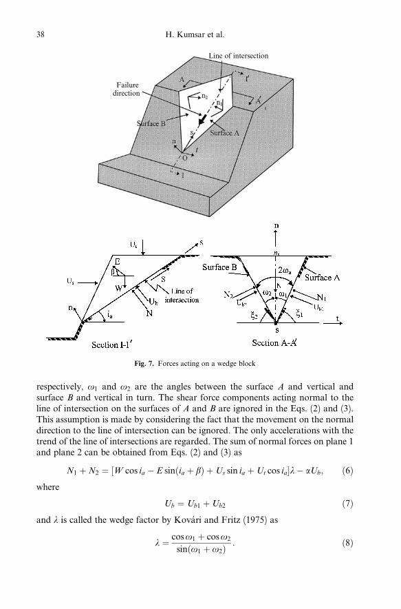
respectively, o1 and o2 are the angles between the surface A and vertical andsurface B and vertical in turn. The shear force components acting normal to theline of intersection on the surfaces of A and B are ignored in the Eqs. (2) and (3).This assumption is made by considering the fact that the movement on the normaldirection to the line of intersection can be ignored. The only accelerations with thetrend of the line of intersections are regarded. The sum of normal forces on plane 1and plane 2 can be obtained from Eqs. (2) and (3) as
N1 �N2 � �W cos ia ÿ E sin�ia � b� �Us sin ia �Ut cos ia�lÿ aUb; �6�where
Ub � Ub1 �Ub2 �7�and l is called the wedge factor by KovaÂri and Fritz (1975) as
l � cos o1 � cos o2
sin�o1 � o2� : �8�
Line of intersection
Failuredirection
Fig. 7. Forces acting on a wedge block
38 H. Kumsar et al.
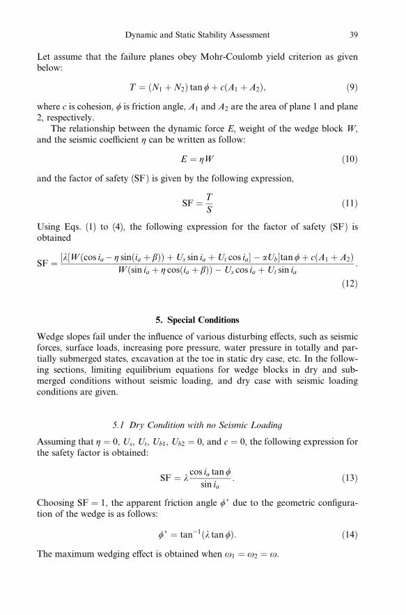
Let assume that the failure planes obey Mohr-Coulomb yield criterion as givenbelow:
T � �N1 �N2� tan f� c�A1 � A2�; �9�where c is cohesion, f is friction angle, A1 and A2 are the area of plane 1 and plane2, respectively.
The relationship between the dynamic force E, weight of the wedge block W,and the seismic coe½cient h can be written as follow:
E � hW �10�and the factor of safety (SF) is given by the following expression,
SF � T
S�11�
Using Eqs. (1) to (4), the following expression for the factor of safety (SF) isobtained
SF � �l�W�cos iaÿ h sin�ia � b�� �Us sin ia �Ut cos ia� ÿ aUb�tan f� c�A1 � A2�W�sin ia � h cos�ia � b�� ÿUs cos ia �Ut sin ia
:
�12�
5. Special Conditions
Wedge slopes fail under the in¯uence of various disturbing e¨ects, such as seismicforces, surface loads, increasing pore pressure, water pressure in totally and par-tially submerged states, excavation at the toe in static dry case, etc. In the follow-ing sections, limiting equilibrium equations for wedge blocks in dry and sub-merged conditions without seismic loading, and dry case with seismic loadingconditions are given.
5.1 Dry Condition with no Seismic Loading
Assuming that h � 0, Us, Ut, Ub1, Ub2 � 0, and c � 0, the following expression forthe safety factor is obtained:
SF � lcos ia tan f
sin ia: �13�
Choosing SF � 1, the apparent friction angle f� due to the geometric con®gura-tion of the wedge is as follows:
f� � tanÿ1�l tan f�: �14�The maximum wedging e¨ect is obtained when o1 � o2 � o.
Dynamic and Static Stability Assessment 39
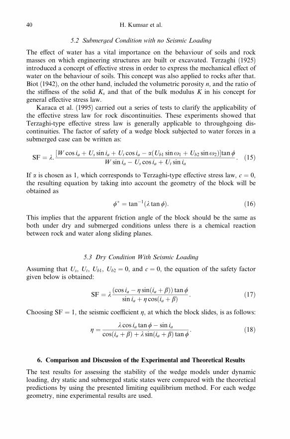
5.2 Submerged Condition with no Seismic Loading
The e¨ect of water has a vital importance on the behaviour of soils and rockmasses on which engineering structures are built or excavated. Terzaghi (1925)introduced a concept of e¨ective stress in order to express the mechanical e¨ect ofwater on the behaviour of soils. This concept was also applied to rocks after that.Biot (1942), on the other hand, included the volumetric porosity n, and the ratio ofthe sti¨ness of the solid Ks and that of the bulk modulus K in his concept forgeneral e¨ective stress law.
Karaca et al. (1995) carried out a series of tests to clarify the applicability ofthe e¨ective stress law for rock discontinuities. These experiments showed thatTerzaghi-type e¨ective stress law is generally applicable to throughgoing dis-continuities. The factor of safety of a wedge block subjected to water forces in asubmerged case can be written as:
SF � l:�W cos ia �Us sin ia �Ut cos ia ÿ a�Ub1 sin o1 �Ub2 sin o2��tan f
W sin ia ÿUs cos ia �Ut sin ia: �15�
If a is chosen as 1, which corresponds to Terzaghi-type e¨ective stress law, c � 0,the resulting equation by taking into account the geometry of the block will beobtained as
f� � tanÿ1�l tan f�: �16�This implies that the apparent friction angle of the block should be the same asboth under dry and submerged conditions unless there is a chemical reactionbetween rock and water along sliding planes.
5.3 Dry Condition With Seismic Loading
Assuming that Us, Ut, Ub1, Ub2 � 0, and c � 0, the equation of the safety factorgiven below is obtained:
SF � l�cos ia ÿ h sin�ia � b�� tan f
sin ia � h cos�ia � b� : �17�
Choosing SF � 1, the seismic coe½cient h, at which the block slides, is as follows:
h � l cos ia tan fÿ sin ia
cos�ia � b� � l sin�ia � b� tan f: �18�
6. Comparison and Discussion of the Experimental and Theoretical Results
The test results for assessing the stability of the wedge models under dynamicloading, dry static and submerged static states were compared with the theoreticalpredictions by using the presented limiting equilibrium method. For each wedgegeometry, nine experimental results are used.
40 H. Kumsar et al.

In the case of dry static test, the plunge of the line of intersection during thefailure of each wedge model is measured. This angle has two components: theplunge of the model (ia) before tilting test, and the tilting angle of the model wedgesurface at failure during tilting test, respectively. The sum of these two angles iscalled the plunge of the wedge model during the sliding in dry static test. Fig. 8compares the theoretical predictions with the experimental results. From thiscomparison it can be stated that the limiting equilibrium method is generally validwhen the strength of a discontinuity is purely frictional (c � 0).
The comparison of the submerged static test results of the wedge blocks andthe theoretical estimation of the plunge during the failure of the wedge block fordi¨erent values of the friction angle (f) and zero cohesion (c), indicate that there isnot a considerable di¨erence among the failure intersection angles under staticloading conditions (Fig. 9). This con®rms that water pressure does not have animportant in¯uence on the stability of wedge models in submerged and c � 0conditions, and Terzaghi-type e¨ective stress law is applicable to rock discon-tinuities. However, if there is a chemical deterioration (such as softening of rock)on discontinuity surfaces due to the presence of water, the stability of a wedgeblock below water table may be in¯uenced.
The results of the dynamic stability tests obtained from the wedge models werecompared with the theoretical estimations (Fig. 10). The theoretical estimationswere done by using Eq. (18) for the plunge of the line of intersection of each typeof wedge model. The friction angle of the discontinuity surfaces, which wasobtained from the tilting test, is taken 35�. The acceleration, that is required tomake the wedge block unstable, is assessed for various half wedge angles. As seenfrom Fig. 10, the results of the dynamic stability tests on the wedge blocks are in agood agreement with those obtained from the presented limiting equilibriummethod. The scattering in Fig. 10 may be attributed to the possible experimentalerrors in sample preparation and to the smoothness of the surfaces. It is suggested
Fig. 8. Comparison of the dry-static model test results with theoretical solutions
Dynamic and Static Stability Assessment 41

that this method can be employed for the stability assessment of the slopes locatedin earthquake-prone regions.
7. Case Studies
A series of stability assessments of failed and stable wedge cases from Turkey andJapan were analysed by using the presented limiting equilibrium method. Thecases from Turkey are, wedge failures in a very high bench at a strip coal mine, inan open museum in the Central Anatolia, in a quarry in Ankara Castle, and in anearthquake prone-region in western Turkey. A wedge failure in an active volcanic
Fig. 9. Comparison of the submerged-static model test results with theoretical solutions
Fig. 10. Comparison of the dynamic model test results with theoretical solutions
42 H. Kumsar et al.
mountain in Japan called Mayuyama was also assessed to check the validity of thepresented method in this study.
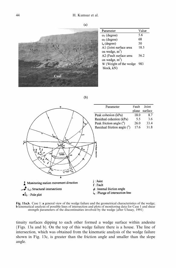
7.1 Case 1: Wedge Failure at a Strip Coal Mine
One of the failures, which a¨ected the operations at Eskihisar strip coal mine, SWTurkey, occurred in the form of a wedge failure. The wedge resulted from the in-tersection of a fault plane and a highly continuous joint (Fig. 11a). Tension cracksof large extent behind the crest after this failure suggested that the movement intothe void was still continuing and a monitoring study was initiated. Then a secondfailure occurred.
On the basis of kinematical analysis of the slope (Fig. 11b) and the backanalysis of the failure using the laboratory determined residual strength parame-ters of both discontinuities, it was concluded that the mode of failure of the pre-vious major instability was wedge type, involving the fault and joint set numbered4 (Ulusay, 1991). In this study, the geometrical parameters from the stereonetprojection, and the weight of this wedge were calculated (Fig. 11a). The shearstrength parameters of the fault plane were accepted to be mobilised and droppedto residual values during the failure (Fig. 11b). The back analysis yielded a safetyfactor of 0.93, which validates the limiting equilibrium method presented in thisstudy. Monitoring station movement directions plotted (Fig. 11b) generally cor-respond to the trend of the line of intersection of the fault and the joint 1. Thissituation indicated that the wedge formed by If , j1 has been activated towards thevoid created by the previous failure.
7.2 Case 2: A Wedge Failure in an Open Museum
A wedge failure in a thick and soft tu¨ stratum was observed by the authors inZelve Open Museum in Cappadocia Region in Central Anatolia. Two joints,intersecting each other, had slightly rough surfaces and formed a tetrahedralwedge (Fig. 12a).
Determination of the internal friction angle of these slightly rough joint sur-faces was carried out by employing the criterion proposed by Barton and Choubey(1977). For this purpose, Schmidt Hammer rebound number and JRC value of thesurfaces were determined, and the laboratory test results by Ulusay et al. (1997)carried out on these tu¨s were also considered. Calculations yielded an internalfriction angle of 30�. The kinematical analysis of the wedge with its geometricalparameters is given in Fig. 12b. The analysis of the failure using the presentedmethod resulted in a factor of safety less than unity, which emphasises that thewedge block has already failed.
7.3 Case 3: Wedge Failure near Ankara Castle
A very old wedge failure in a jointed andesite rock mass near Ankara Castle inBent Deresi region of Ankara City was investigated by the authors. Two discon-
Dynamic and Static Stability Assessment 43
tinuity surfaces dipping to each other formed a wedge surface within andesite(Figs. 13a and b). On the top of this wedge failure there is a house. The line ofintersection, which was obtained from the kinematic analysis of the wedge failureshown in Fig. 13c, is greater than the friction angle and smaller than the slopeangle.
Fig. 11a,b. Case 1: a general view of the wedge failure and the geometrical characteristics of the wedge;b kinematical analysis of possible lines of intersection and plots of monitoring data for Case 1 and shear
strength parameters of the discontinuities involved by the wedge (after Ulusay, 1991)
44 H. Kumsar et al.

Under these conditions the wedge block is expected to be unstable. In theanalysis, a friction angle of 30� determined from laboratory tests on joint samplesby Ercanoglu (1997) was used. The stability assessment of the wedge block underdry-static condition was carried out by using the suggested method in this paper.The safety factor of the slope was found as 0.73, which clari®es that the slope hasalready failed.
7.4 Case 4: Wedge Failure at an Earthquake-prone Area
The town of Dinar is located at an earthquake-prone area in the western Turkey.An earthquake with a magnitude of 6.0 occurred in Dinar and its vicinity onOctober 1, 1995. During this disaster 90 people lost their lives and many housescollapsed and were damaged.
After the earthquake, ®eld studies were carried out and a wedge failure wasobserved northeast of Kizilli Village near Dinar. This failure is located at the faultzone of Dinar (Fig. 14a). A kinematical analysis was done to determine the nec-essary wedge parameters for the stability assessment of the wedge block (Fig.14b). The internal friction angle of the joint surfaces was determined by perform-ing a simple tilting test in the ®eld and found as 41�.
A back analysis of the wedge failure, using the proposed method, was carriedout to check the in¯uence of the seismic force due to Dinar earthquake on the
Fig. 12a,b. Case 2: a a wedge failure in Zelve at Cappadocia; b its kinematical analysis and geometricalcharacteristics
(a) (b)
Dynamic and Static Stability Assessment 45

stability of the wedge block by considering static conditions. A factor of safety of2.02 was obtained, which indicates that the wedge block is stable under staticconditions. Therefore, a second analysis which takes dynamic conditions intoaccount was performed by using the amax value in EW direction (Aydan andKumsar, 1997), given in Fig. 14. The value of the safety factor for this directionwas 0.99. This result revealed that the slope instability was initiated when theearthquake occurred on October 1, 1995.
7.5 Case 5: Wedge Failure of Mt. Mayuyama in 1792
Mt. Mayuyama in Japan failed following an earthquake about 8 pm and resultedin the loss of 15000 people during a volcanic activity of Unzen volcanos in 1792. Aslope failure also occurred during this disaster. The authors carried out a series ofback analyses considering di¨erent conditions to discuss the mechanism and themodel of this wedge type slope failure.
Fig. 13a±c. Case 3: a view of the wedge failure near Ankara Castle; b close up view from the wedgenear Ankara Castle; c the kinematical analysis and the geometrical characteristics of the wedge
(a) (b)
(c)
46 H. Kumsar et al.

There are three di¨erent explanations of the failure of Mt. Mayuyama(Misawa et al., 1993):
1. Failure due to earthquake,2. Failure due to gas pressure of heated ground water, and3. Failure due to liquefaction of an underlying sandy layer.
Four cross-sections of the failed body are given in Fig. 15. From these sectionsit was concluded that there are three distinct failure planes, namely J1, J2 and J3,and their projections on a lower hemisphere Schmidt net and wedge parametersfor the stability assessment of the wedge block are given in Fig. 16.
Fig. 14a,b. Case 4: a the wedge failure occurred northeast of Kõzõllõ Village (Dinar) after the 1995earthquake; b the kinematical analysis and the geometrical characteristics of the wedge
(a)
(b)
Dynamic and Static Stability Assessment 47

The planes J1 and J2 are the planes which should be developed long time(Ohta, 1987). However, the plane J3 was considered to have developed during thevolcanic activity and associated earthquake in 1792, since there is thin vegetation
Fig. 15. Present topography and cross-sections of the close vicinity of Mt. Mayuyama (after Misawaet al., 1993)
Fig. 16. Kinematical analyses of the wedge blocks at Mt. Mayuyama and the geometrical character-istics of the wedge
48 H. Kumsar et al.
on this surface (Misawa et al., 1993). There are two possible wedge failures asshown in Fig. 16. Since the dip of the intersection of the planes J1 and J2 is greaterthan the slope angle, the wedge failure along these discontinuity planes is notkinematically possible. On the other hand the wedge failure on planes J1 and J3 isthe most likely as the plunge of the intersection line daylights on the slope face.The geometrical parameters of the wedge were determined and given in Fig. 16.
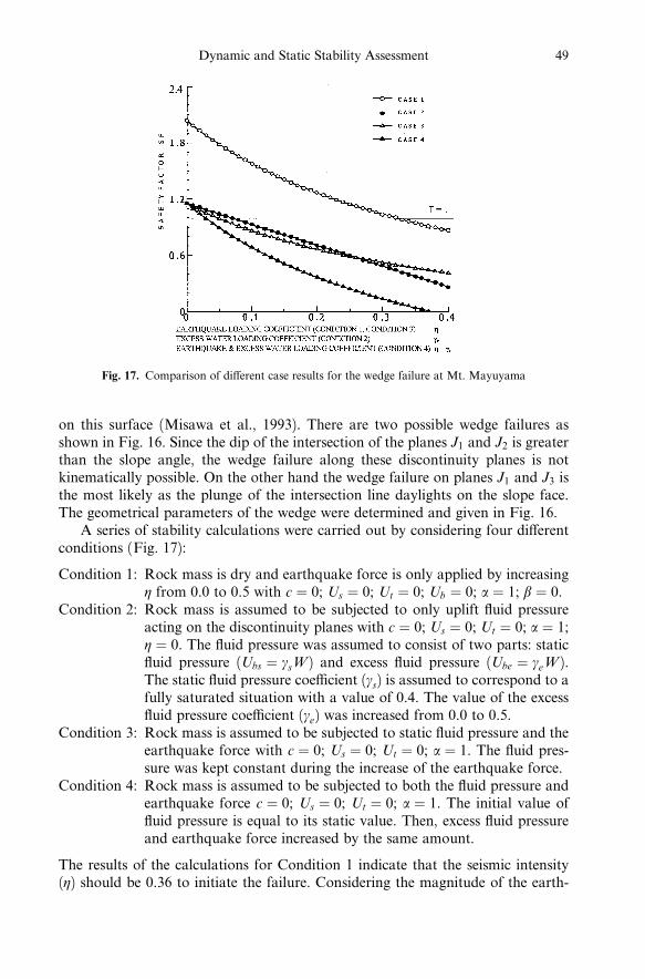
A series of stability calculations were carried out by considering four di¨erentconditions (Fig. 17):
Condition 1: Rock mass is dry and earthquake force is only applied by increasingh from 0.0 to 0.5 with c � 0; Us � 0; Ut � 0; Ub � 0; a � 1; b � 0.
Condition 2: Rock mass is assumed to be subjected to only uplift ¯uid pressureacting on the discontinuity planes with c � 0; Us � 0; Ut � 0; a � 1;h � 0. The ¯uid pressure was assumed to consist of two parts: static¯uid pressure (Ubs � gsW ) and excess ¯uid pressure (Ube � geW ).The static ¯uid pressure coe½cient (gs) is assumed to correspond to afully saturated situation with a value of 0.4. The value of the excess¯uid pressure coe½cient (ge) was increased from 0.0 to 0.5.
Condition 3: Rock mass is assumed to be subjected to static ¯uid pressure and theearthquake force with c � 0; Us � 0; Ut � 0; a � 1. The ¯uid pres-sure was kept constant during the increase of the earthquake force.
Condition 4: Rock mass is assumed to be subjected to both the ¯uid pressure andearthquake force c � 0; Us � 0; Ut � 0; a � 1. The initial value of¯uid pressure is equal to its static value. Then, excess ¯uid pressureand earthquake force increased by the same amount.
The results of the calculations for Condition 1 indicate that the seismic intensity(h) should be 0.36 to initiate the failure. Considering the magnitude of the earth-
Fig. 17. Comparison of di¨erent case results for the wedge failure at Mt. Mayuyama
Dynamic and Static Stability Assessment 49
quake at the time of failure, it is not possible that the mountain can fail withoutthe e¨ect of ¯uid pressure.
The mountain should be stable under the fully saturated condition accordingto the calculation results for Condition 2. However, if the excess pressure is tooccur, the mountain failure could be initiated when the excess ¯uid pressure is 0.12times the dead weight of the wedge body. If the excess ¯uid pressure is due to theheating of groundwater by the magma, the mountain failure is possible.
If the rock mass is fully saturated without generation of excess ¯uid pressure(Condition 3), the increase of seismic intensity h can also cause the failure of themountain for a value of 0.08. If the Condition 4 is considered, the failure of themountain can occur for a value of 0.05.
At the time of failure, an earthquake did happen and the hot water did spoutfrom the ground. Therefore, it is most likely that the forces due to the earthquakeand the ¯uid pressure caused by the gravity, shaking and heating of the ground-water could be the main reasons for the failure of the mountain. Nevertheless, itshould be kept in mind that the observation of the hot water spewing out of theground near the coast may also be caused by the energy dissipation releasedduring the frictional sliding of the failing mountain.
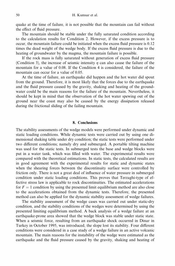
8. Conclusions
The stability assessments of the wedge models were performed under dynamic andstatic loading conditions. While dynamic tests were carried out by using one di-mensional shaking table under dry condition; the static tests were performed undertwo di¨erent conditions; namely dry and submerged. A portable tilting machinewas used for the static tests. In submerged tests the base and wedge blocks wereput in a water tank, which was ®lled with water. The experimental results werecompared with the theoretical estimations. In static tests, the calculated results arein good agreement with the experimental results for static and dynamic stateswhen the shearing forces between the discontinuity surface were controlled byfriction only. There is not a great deal of in¯uence of water pressure in submergedcondition under static loading conditions. This proves that Terzaghi-type of ef-fective stress law is applicable to rock discontinuities. The estimated accelerationsfor F � 1 condition by using the presented limit equilibrium method are also closeto the accelerations obtained from the dynamic tests. Therefore, the presentedmethod can also be applied for the dynamic stability assessment of wedge failures.
The stability assessment of the wedge cases was carried out under static-drycondition, and the stability conditions of the wedges were determined by using thepresented limiting equilibrium method. A back analysis of a wedge failure at anearthquake-prone area showed that the wedge block was stable under static state.When a seismic force, resulting from an earthquake shock occurred in Dinar inTurkey in October 1995, was introduced, the slope lost its stability. Four di¨erentconditions were considered in a case study of a wedge failure in an active volcanicmountain. The main reasons for the instability of the wedge were estimated as theearthquake and the ¯uid pressure caused by the gravity, shaking and heating of
50 H. Kumsar et al.

the groundwater. These case studies also show the validity of the limiting equilib-rium approach.
References
Aydan, OÈ ., Kumsar, H. (1997): A site investigation of Dinar earthquake of October 1,1995. Turkish Earthquake Foundation, TDV/DR 97-003, Istanbul, Turkey, 115 pp.
Aydan, OÈ ., Shimizu, Y., Kawamoto, T. (1995): A portable system for in-situ characteriza-tion of surface morphology and frictional properties of rock discontinuities. Proc., 4th
Int. Symp. on Field Measurements in Geomechanics, Bergamo, Italy, 463±470.
Barton, N. R., Choubey, V. (1977): The shear strength of rock joints in theory and practice.Rock Mech. 10, 1±54.
Biot, A. M. (1942): The theory of three dimensional consolidation, J. Apply. Phys. 12, 155±165.
Ercanoglu, M. (1997): Altindag (Ankara) yerlesim boÈ lgesindeki andezitlerde olasi sevduraysizlik modellerinin incelenmesi ve duraysizlik haritasinin olusturulmasi. YuÈksekLisans Tezi, Hacettepe UÈ niversitesi Fen Bilimleri EnstituÈsuÈ , Ankara, 83 pp (in Turkish).
Hoek, E., Bray, J. W. (1981): Rock slope engineering, 3rd edn. Institute of Mining andMetallurgy, London, 358 pp.
Karaca, M., Sezaki, M., Aydan, OÈ . (1995): Assessing the mechanical response of rockstructures subject to water forces. Proc., 35th US Rock Mechanics Symp., Lake Tahoe,335±340.
KovaÂri, K., Fritz, P. (1975): Stability analysis of rock slopes for plane and wedgefailure with the aid of a programmable pocket calculator. 16th US Rock Mech. Symp.,Minneapolis, USA, 25±33.
Misawa, Y., Aydan, OÈ ., Hamada, M. (1993): A consideration on the failure of Mt.Mayuyama in 1792 from rock mechanics view point. Proc., Int. Symp. on Assessmentand Prevention of Failure Phenomena in Rock Engineering, Istanbul, Turkey, 871±877.
Ohta, K. (1987): Geological structure of Unzen Volcano and its relation to the volcanicphenomena. Chidanken Symp. 33 (7) 71±85 (in Japanese).
Terzaghi, K. (1925): Erdbaumechanik auf bodenphysikalischer Grundlage. F. Deuticke'sVerlag, Leipzig.
Ulusay, R. (1991): Geotechnical evaluations and deterministic design considerations forpitwall slopes at Eskihisar (Yatagan±Mugla) strip coal mine. PhD Thesis, Middle EastTechnical University, Ankara, Turkey, 340 pp.
Ulusay, R., GoÈkcËeoglu, C., Binal, A. (1997): Physical and mechanical properties of the tu¨samples from Cappadocia Region. Report of Hacettepe University, Geological Engi-neering Department, 32 pp.
Wittke, W. (1967): In¯uence of the shear strength of joints on the design of prestressedanchors to stabilize a rock slope. Geotechnical Conference, Oslo, Paper No. 4.11, 311±318.
Authors' address: Dr. Halil Kumsar, Pamukkale University, Department of GeologicalEngineering, Kinikli Kampusu, TR-20017 Denizli, Turkey.
Dynamic and Static Stability Assessment 51