dump truck hm300 -2 - coppard hm300-2...foreword foreword foreword this manual provides rules and...
TRANSCRIPT
ARTICULATEDDUMP TRUCK
PEN00101-04
HM300-2
SERIAL NUMBERS 2001 and up
Unsafe Use of this machine may cause serious injury orDeath.Operators and maintenance personnel must readthis manual before operating or maintaining this machine.This manual should be kept near the machine for reference and periodically reviewed by all personnel who will come into contact with it .
WARNING
Komatsu has Operation & Maintenance Manuals written in some other languages. if a foreign language manual is necessary, contact your local distributor for availability.
NOTICE

.
1 - 1
.
FOREWORDFOREWORD
FOREWORDThis manual provides rules and guidelines which will help you use this machine safely and effectively. Theprecautions in this manual must be followed at all times when performing operation and maintenance. Mostaccidents are caused by the failure to follow fundamental safety rules for the operation and maintenance ofmachines. Accidents can be prevented by knowing beforehand conditions that may cause a hazard whenperforming operation and maintenance.
WARNINGOperators and maintenance personnel must always do as follows before beginning operation or maintenance.
Always be sure to read and understand this manual thoroughly before performing operation and maintenance.
Read the safety messages given in this manual and the safety labels affixed to the machine thoroughly and be sure that youunderstand them fully.
Keep this manual in the storage location for the operation and maintenance manual given below, and have all personnel read itperiodically.
If this manual has been lost or has become dirty and cannot be read, request a replacement manual immediately from Komatsuor your Komatsu distributor.
If you sell the machine, be sure to give this manual to the new owners together with the machine.
Komatsu delivers machines that comply with all applicable regulations and standards of the country to which it has been shipped.If this machine has been purchased in another country or purchased from someone in another country, it may lack certain safetydevices and specifications that are necessary for use in your country. If there is any question about whether your productcomplies with the applicable standards and regulations of your country, consult Komatsu or your Komatsu distributor beforeoperating the machine.
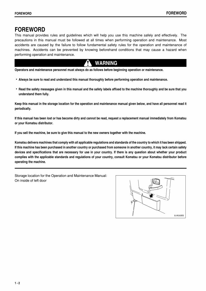
Storage location for the Operation and Maintenance Manual:On inside of left door
1 - 2
.
FOREWORD FOREWORD
1 - 3
.
FOREWORDFOREWORD
1 - 4
.
FOREWORD SAFETY INFORMATION
SAFETY INFORMATIONTo enable you to use this machine safely, safety precautions and labels are given in this manual and affixed to themachine to give explanations of situations involving potential hazards and of the methods of avoiding suchsituations.
Signal words
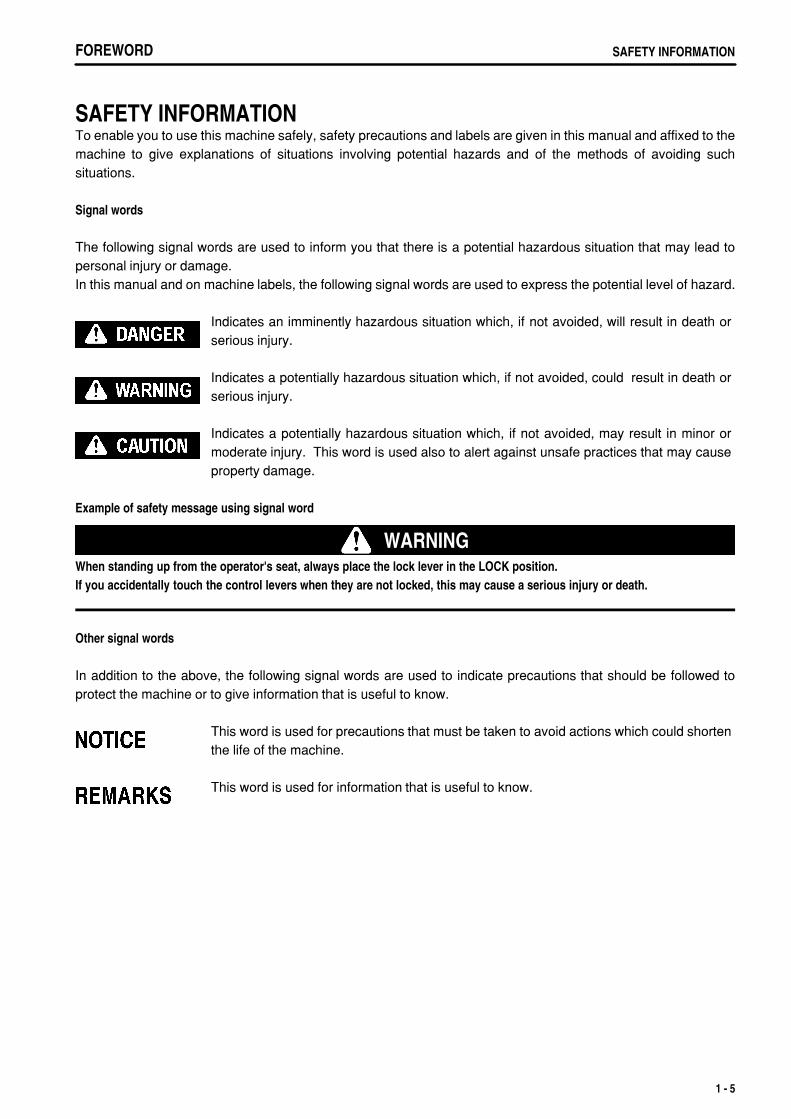
The following signal words are used to inform you that there is a potential hazardous situation that may lead topersonal injury or damage.In this manual and on machine labels, the following signal words are used to express the potential level of hazard.
Indicates an imminently hazardous situation which, if not avoided, will result in death orserious injury.
Indicates a potentially hazardous situation which, if not avoided, could result in death orserious injury.
Indicates a potentially hazardous situation which, if not avoided, may result in minor ormoderate injury. This word is used also to alert against unsafe practices that may causeproperty damage.
Example of safety message using signal word
WARNINGWhen standing up from the operator's seat, always place the lock lever in the LOCK position.If you accidentally touch the control levers when they are not locked, this may cause a serious injury or death.
Other signal words
In addition to the above, the following signal words are used to indicate precautions that should be followed toprotect the machine or to give information that is useful to know.
This word is used for precautions that must be taken to avoid actions which could shortenthe life of the machine.
This word is used for information that is useful to know.
1 - 5
.
FOREWORDSAFETY INFORMATION
Safety labels
Safety labels are affixed to the machine to inform the operator or maintenance worker on the spot when carrying outoperation or maintenance of the machine that may involve hazard.This machine uses "Safety labels using words" and "Safety labels using pictograms" to indicate safety procedures.
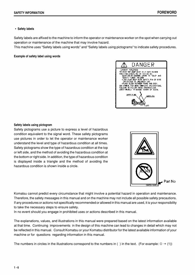
Example of safety label using words
Safety labels using pictogramSafety pictograms use a picture to express a level of hazardouscondition equivalent to the signal word. These safety pictogramsuse pictures in order to let the operator or maintenance workerunderstand the level and type of hazardous condition at all times.Safety pictograms show the type of hazardous condition at the topor left side, and the method of avoiding the hazardous condition atthe bottom or right side. In addition, the type of hazardous conditionis displayed inside a triangle and the method of avoiding thehazardous condition is shown inside a circle.
Komatsu cannot predict every circumstance that might involve a potential hazard in operation and maintenance.Therefore, the safety messages in this manual and on the machine may not include all possible safety precautions.If any procedures or actions not specifically recommended or allowed in this manual are used, it is your responsibilityto take the necessary steps to ensure safety.In no event should you engage in prohibited uses or actions described in this manual.
The explanations, values, and illustrations in this manual were prepared based on the latest information availableat that time. Continuing improvements in the design of this machine can lead to changes in detail which may notbe reflected in this manual. Consult Komatsu or your Komatsu distributor for the latest available information of yourmachine or for questions regarding information in this manual.
The numbers in circles in the illustrations correspond to the numbers in ( ) in the text. (For example: 1 (1))
1 - 6
.
FOREWORD INTENDED USE
INTENDED USE
DIRECTIONS OF MACHINE
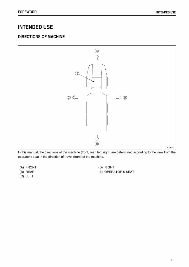
In this manual, the directions of the machine (front, rear, left, right) are determined according to the view from theoperator's seat in the direction of travel (front) of the machine.
(A)(B)(C)
FRONTREARLEFT
(D)(E)
RIGHTOPERATOR'S SEAT
1 - 7
.
FOREWORDLOCATION OF PLATES, TABLE TO ENTER SERIAL NO. AND DISTRIBUTOR
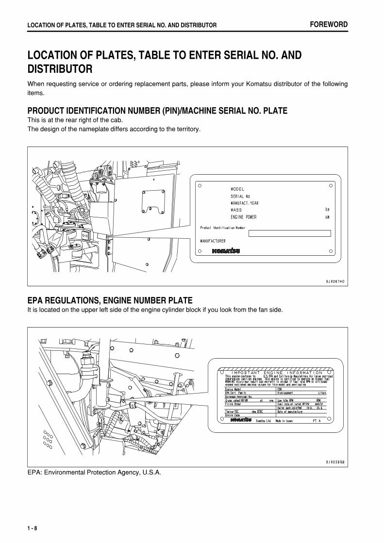
LOCATION OF PLATES, TABLE TO ENTER SERIAL NO. AND DISTRIBUTORWhen requesting service or ordering replacement parts, please inform your Komatsu distributor of the followingitems.
PRODUCT IDENTIFICATION NUMBER (PIN)/MACHINE SERIAL NO. PLATEThis is at the rear right of the cab.The design of the nameplate differs according to the territory.
EPA REGULATIONS, ENGINE NUMBER PLATEIt is located on the upper left side of the engine cylinder block if you look from the fan side.
EPA: Environmental Protection Agency, U.S.A.
1 - 8
.
FOREWORD LOCATION OF PLATES, TABLE TO ENTER SERIAL NO. AND DISTRIBUTOR
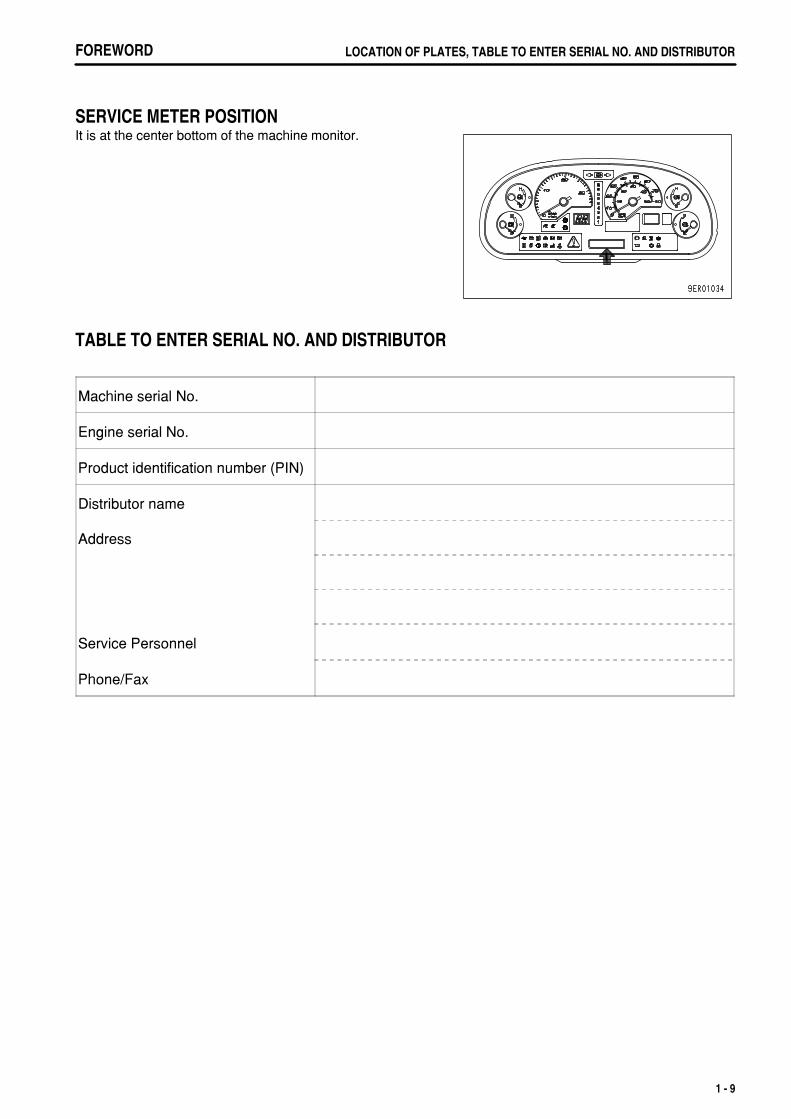
SERVICE METER POSITIONIt is at the center bottom of the machine monitor.
TABLE TO ENTER SERIAL NO. AND DISTRIBUTOR
Machine serial No.
Engine serial No.
Product identification number (PIN)
Distributor name
Address
Service Personnel
Phone/Fax
1 - 9
.
FOREWORDCONTENTS
CONTENTSFOREWORD 1- 1 FOREWORD 1- 2 SAFETY INFORMATION 1- 5 INTENDED USE 1- 7 DIRECTIONS OF MACHINE 1- 7 LOCATION OF PLATES, TABLE TO ENTER SERIAL NO. AND DISTRIBUTOR 1- 8 PRODUCT IDENTIFICATION NUMBER (PIN)/MACHINE SERIAL NO. PLATE 1- 8 EPA REGULATIONS, ENGINE NUMBER PLATE 1- 8 SERVICE METER POSITION 1- 9 TABLE TO ENTER SERIAL NO. AND DISTRIBUTOR 1- 9SAFETY 2- 1 SAFETY 2- 2 SAFETY LABELS 2- 4 POSITION FOR ATTACHING SAFETY LABELS 2- 5 SAFETY LABELS 2- 6 GENERAL PRECAUTIONS 2- 11 PRECAUTIONS DURING OPERATION 2- 20 STARTING ENGINE 2- 20 OPERATION 2- 22 TRANSPORTATION 2- 26 BATTERY 2- 27 TOWING 2- 29 PRECAUTIONS FOR MAINTENANCE 2- 30 PRECAUTIONS WITH TIRES 2- 37OPERATION 3- 1 GENERAL VIEW 3- 2 GENERAL VIEW OF MACHINE 3- 2 GENERAL VIEW OF CONTROLS AND GAUGES 3- 3 EXPLANATION OF COMPONENTS 3- 5 MACHINE MONITOR 3- 5 OTHER FUNCTIONS OF MACHINE MONITOR 3- 26 SWITCHES 3- 30 CONTROL LEVERS AND PEDALS 3- 40 BODY PIVOT PIN 3- 45 ARTICULATE LOCK 3- 45 LOCATION OF FIRE EXTINGUISHER 3- 46 DUST INDICATOR 3- 46 CIRCUIT BREAKER 3- 46 FUSES 3- 47 CAR RADIO 3- 50 CAR STEREO 3- 56 AIR CONDITIONER 3- 64 OPERATION 3- 70 CHECK BEFORE STARTING ENGINE 3- 70 STARTING ENGINE 3- 85 OPERATIONS, CHECKS AFTER STARTING ENGINE 3- 87 STOPPING ENGINE 3- 88 CHECKS AFTER STOPPING ENGINE 3- 88 MOVING MACHINE OFF (FORWARD, REVERSE), STOPPING 3- 89
1 - 10

.
FOREWORD CONTENTS
SHIFTING GEAR 3- 94 TRAVELING DOWNHILL 3- 96 STEERING THE MACHINE 3-102 OPERATION USING DIFFERENTIAL LOCK 3-103 LOADING OPERATIONS 3-104 DUMP OPERATIONS 3-105 CAB TILT OPERATION 3-107 PRECAUTIONS FOR OPERATION 3-110 PARKING MACHINE 3-111 CHECKS AFTER COMPLETION OF WORK 3-112 LOCKING 3-112 HANDLING TIRES 3-113 DETERMINING AND MAINTAINING TRAVEL ROAD 3-114 DETERMINING TRAVEL ROAD 3-114 MAINTAINING TRAVEL ROAD 3-114 TRANSPORTATION 3-115 PRECAUTIONS WHEN TRANSPORTING 3-115 STEPS FOR TRANSPORTATION 3-115 METHOD OF SECURING MACHINE 3-116 METHOD OF LIFTING MACHINE 3-117 COLD WEATHER OPERATION 3-121 PRECAUTIONS FOR LOW TEMPERATURE 3-121 PRECAUTIONS AFTER COMPLETION OF WORK 3-122 AFTER COLD WEATHER 3-123 LONG-TERM STORAGE 3-124 BEFORE STORAGE 3-124 DURING STORAGE 3-124 AFTER STORAGE 3-124 PRECAUTIONS BEFORE TRAVELING AFTER LONG-TERM STORAGE 3-124 TROUBLESHOOTING 3-125 AFTER RUNNING OUT OF FUEL 3-125 IF TRANSMISSION HAS TROUBLE 3-126 METHOD OF LOWERING DUMP BODY IN EMERGENCY 3-126 METHOD OF TOWING MACHINE 3-127 IF BATTERY IS DISCHARGED 3-131 OTHER TROUBLE 3-135MAINTENANCE 4- 1 GUIDES TO MAINTENANCE 4- 2 OUTLINE OF SERVICE 4- 4 HANDLING OIL, FUEL, COOLANT, AND PERFORMING OIL CLINIC 4- 4 OUTLINE OF ELECTRIC SYSTEM 4- 8 WEAR PARTS 4- 9 WEAR PARTS LIST 4- 9 RECOMMENDED FUEL, COOLANT, AND LUBRICANT 4- 10 USE OF FUEL, COOLANT AND LUBRICANTS ACCORDING TO AMBIENT TEMPERATURE 4- 11 RECOMMENDED BRANDS, RECOMMENDED QUALITY FOR PRODUCTS OTHER THAN KOMATSU GENUINE OIL 4- 12 STANDARD TIGHTENING TORQUES FOR BOLTS AND NUTS 4- 13 TORQUE LIST 4- 13 PERIODIC REPLACEMENT OF SAFETY CRITICAL PARTS 4- 15
1 - 11
.
FOREWORDCONTENTS
SAFETY CRITICAL PARTS 4- 16 MAINTENANCE SCHEDULE CHART 4- 17 MAINTENANCE SCHEDULE CHART 4- 17 SERVICE PROCEDURE 4- 19 INITIAL 250 HOURS SERVICE (ONLY AFTER THE FIRST 250 HOURS) 4- 19 WHEN REQUIRED 4- 20 CHECK BEFORE STARTING 4- 39 EVERY 50 HOURS SERVICE 4- 40 EVERY 250 HOURS SERVICE 4- 41 EVERY 500 HOURS SERVICE 4- 53 EVERY 1000 HOURS SERVICE 4- 60 EVERY 2000 HOURS SERVICE 4- 71 EVERY 4000 HOURS SERVICE 4- 77 EVERY 6000 HOURS SERVICE 4- 79 EVERY 8000 HOURS SERVICE 4- 80SPECIFICATIONS 5- 1 SPECIFICATIONS 5- 2ATTACHMENTS, OPTIONS 6- 1 HANDLING AUTOMATIC RETARDER, ACCELERATOR CONTROL(ARAC) 6- 2 EXPLANATION OF COMPONENTS 6- 2 METHOD OF OPERATION 6- 3 USE OF REAR VIEW MONITOR 6- 4 NAME AND FUNCTON OF EACH PART OF REAR VIEW MONITOR 6- 4 SETTING OF REAR VIEW MONITOR 6- 7 CAUTIONS WHEN USING REAR VIEW MONITOR 6- 7 HANDLING DUMPING COUNTER 6- 8 HANDLING MACHINES EQUIPPED WITH KOMTRAX 6- 9 BASIC PRECAUTIONS 6- 9INDEX 7- 1
1 - 12
.
2 - 1
.
SAFETYSAFETY
SAFETY
SAFETY LABELS 2- 4 POSITION FOR ATTACHING SAFETY LABELS 2- 5 SAFETY LABELS 2- 6
GENERAL PRECAUTIONS 2- 11 SAFETY RULES 2- 11 IF ABNORMALITIES ARE FOUND 2- 11 CLOTHING AND PERSONAL PROTECTIVE ITEMS 2- 11 FIRE EXTINGUISHER AND FIRST AID KIT 2- 11 SAFETY FEATURES 2- 12 KEEP MACHINE CLEAN 2- 12 INSIDE OPERATOR'S COMPARTMENT 2- 12 ALWAYS APPLY LOCK WHEN LEAVING OPERATOR'S SEAT 2- 12 HANDRAILS AND STEPS 2- 13 MOUNTING AND DISMOUNTING 2- 13 CRUSHING OR CUTTING PREVENTION 2- 13 PREVENTION OF BURNS 2- 14 FIRE PREVENTION 2- 15 ACTION IF FIRE OCCURS 2- 15 WINDOW WASHER LIQUID 2- 16 PRECAUTIONS WHEN USING ROPS (Roll Over Protective Structure) 2- 16 PRECAUTIONS FOR ATTACHMENTS, OPTIONS 2- 16 UNAUTHORIZED MODIFICATION 2- 16 SAFETY AT WORKSITE 2- 16 WORKING ON LOOSE GROUND 2- 17 DO NOT GO CLOSE TO HIGH-VOLTAGE CABLES 2- 17 ENSURE GOOD VISIBILITY 2- 18 PRECAUTIONS RELATED TO VENTILATION OF EXHAUST GAS 2- 18 CHECKING SIGNALMAN'S SIGNALS AND SIGNS 2- 18 EMERGENCY ESCAPE FROM OPERATOR'S CAB 2- 18 ASBESTOS DUST HAZARD PREVENTION 2- 19
2 - 2
.
SAFETY SAFETY
PRECAUTIONS DURING OPERATION 2- 20 STARTING ENGINE 2- 20 CHECKS BEFORE STARTING ENGINE, ADJUST 2- 20 PRECAUTIONS WHEN STARTING 2- 20 PRECAUTIONS IN COLD AREAS 2- 21 OPERATION 2- 22 CHECKS BEFORE STARTING OPERATION 2- 22 PRECAUTIONS WHEN TRAVELING IN FORWARD OR REVERSE 2- 22 PRECAUTIONS WHEN TRAVELING 2- 23 PRECAUTIONS WHEN TRAVELING ON SLOPES 2- 23 PRECAUTIONS WHEN OPERATING DUMP BODY 2- 24 PRECAUTIONS WHEN OPERATING 2- 24 PRECAUTIONS FOR ACCUMULATED SNOW, ICE 2- 24 PARKING MACHINE 2- 25 TRANSPORTATION 2- 26 LOADING AND UNLOADING 2- 26 SHIPPING 2- 26 BATTERY 2- 27 BATTERY HAZARD PREVENTION 2- 27 STARTING WITH BOOSTER CABLES 2- 28 TOWING 2- 29 WHEN TOWING 2- 29
PRECAUTIONS FOR MAINTENANCE 2- 30 WARNING TAG 2- 30 KEEP WORK PLACE CLEAN AND TIDY 2- 30 APPOINT LEADER WHEN WORKING WITH OTHERS 2- 30 STOP ENGINE BEFORE CARRYING OUT INSPECTION AND MAINTENANCE 2- 31 TWO WORKERS FOR MAINTENANCE WHEN ENGINE IS RUNNING 2- 32 PROPER TOOLS 2- 33 HANDLING SUSPENSION CYLINDER, ACCUMULATOR 2- 33 PERSONNEL 2- 33 WORK UNDER THE MACHINE 2- 33 NOISE 2- 33 PRECAUTIONS WHEN USING HAMMER 2- 34 REPAIR WELDING 2- 34 REMOVING BATTERY TERMINAL 2- 34 PRECAUTIONS WITH HIGH-PRESSURE OIL 2- 34 PRECAUTIONS FOR HIGH-PRESSURE FUEL 2- 34 HANDLING HIGH-PRESSURE HOSES, PIPING 2- 35 PRECAUTIONS FOR HIGH VOLTAGE 2- 35 WASTE MATERIALS 2- 35 MAINTENANCE OF AIR CONDITIONER 2- 35 COMPRESSED AIR 2- 35 PERIODIC REPLACEMENT OF SAFETY-CRITICAL PARTS 2- 36
PRECAUTIONS WITH TIRES 2- 37 HANDLING TIRES 2- 37 PRECAUTIONS WHEN STORING TIRE 2- 37
2 - 3

.
SAFETYSAFETY LABELS
SAFETY LABELS
The following warning signs and safety labels are used on this machine.Be sure that you fully understand the correct position and content of labels.To ensure that the content of labels can be read properly, be sure that they are in the correct place and alwayskeep them clean. When cleaning them, do not use organic solvents or gasoline. These may cause the labels topeel off.There are also other labels in addition to the warning signs and safety labels. Handle those labels in the sameway.If the labels are damaged, lost, or cannot be read properly, replace them with new ones. For details of the partnumbers for the labels, see this manual or the actual label, and place an order with Komatsu distributor.
2 - 4
.
SAFETY SAFETY LABELS
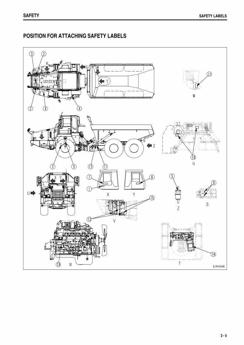
POSITION FOR ATTACHING SAFETY LABELS
2 - 5
.
SAFETYSAFETY LABELS
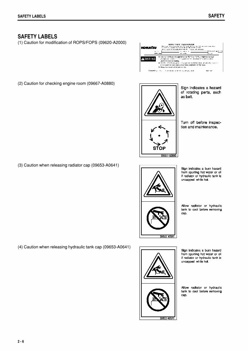
SAFETY LABELS(1) Caution for modification of ROPS/FOPS (09620-A2000)
(2) Caution for checking engine room (09667-A0880)
(3) Caution when releasing radiator cap (09653-A0641)
(4) Caution when releasing hydraulic tank cap (09653-A0641)
2 - 6
.
SAFETY SAFETY LABELSSAFETY SAFETY LABELS
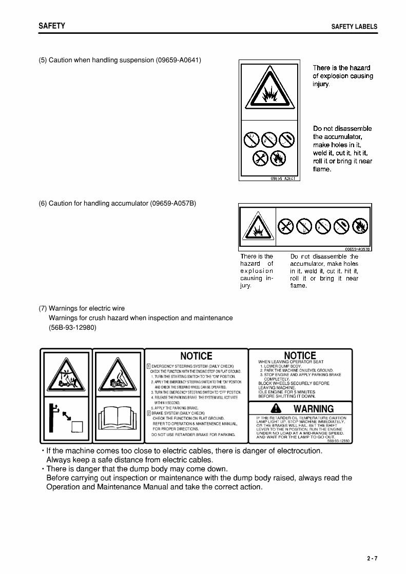
(5) Caution when handling suspension (09659-A0641)
(6) Caution for handling accumulator (09659-A057B)
(7) Warnings for electric wireWarnings for crush hazard when inspection and maintenance(56B-93-12980)
2 - 7
.
SAFETYSAFETY LABELS
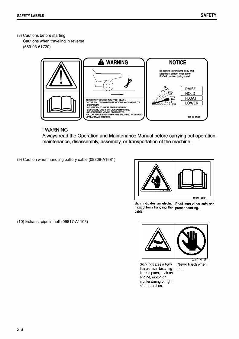
(8) Cautions before startingCautions when traveling in reverse(569-93-61720)
(9) Caution when handling battery cable (09808-A1681)
(10) Exhaust pipe is hot! (09817-A1103)
2 - 8
.
SAFETY SAFETY LABELSSAFETY SAFETY LABELS
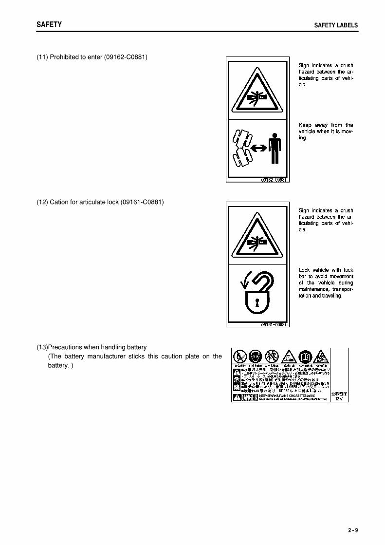
(11) Prohibited to enter (09162-C0881)
(12) Cation for articulate lock (09161-C0881)
(13)Precautions when handling battery(The battery manufacturer sticks this caution plate on thebattery. )
2 - 9
.
SAFETYSAFETY LABELS SAFETYSAFETY LABELS
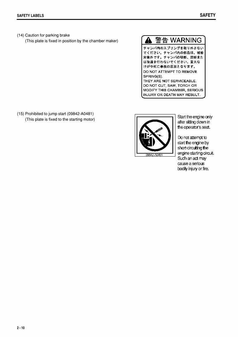
(14) Caution for parking brake(This plate is fixed in position by the chamber maker)
(15) Prohibited to jump start (09842-A0481)(This plate is fixed to the starting motor)
2 - 10
.
SAFETY GENERAL PRECAUTIONS
GENERAL PRECAUTIONS
SAFETY RULESOnly trained and authorized personnel can operate and maintain the machine.Follow all safety rules, precautions and instructions in this manual when operating or performing maintenance onthe machine.If you are not feeling well, or if you are under the influence of alcohol or medication, your ability to safely operateor repair your machine may be severely impaired, putting yourself and everyone else on your job site in danger.When working with another operator or with the person on the worksite traffic duty, discuss the content of theoperation beforehand and use the determined signals when carrying out the operation.
IF PROBLEMS ARE FOUNDIf you find any problems in the machine during operation or maintenance (noise, vibration, smell, incorrect gauges,smoke, oil leakage, etc., or any abnormal display on the warning devices or monitor), report to the person in chargeand have the necessary action taken. Do not operate the machine until the problem has been corrected.
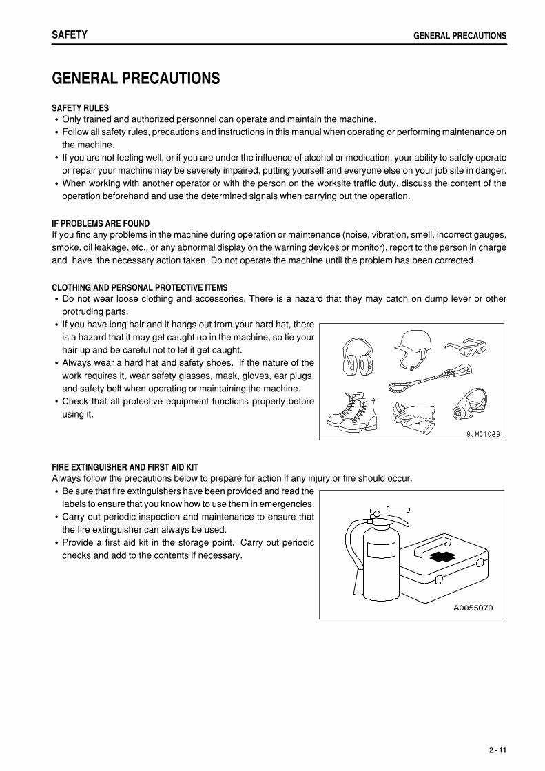
CLOTHING AND PERSONAL PROTECTIVE ITEMSDo not wear loose clothing and accessories. There is a hazard that they may catch on dump lever or otherprotruding parts.If you have long hair and it hangs out from your hard hat, thereis a hazard that it may get caught up in the machine, so tie yourhair up and be careful not to let it get caught.Always wear a hard hat and safety shoes. If the nature of thework requires it, wear safety glasses, mask, gloves, ear plugs,and safety belt when operating or maintaining the machine.Check that all protective equipment functions properly beforeusing it.
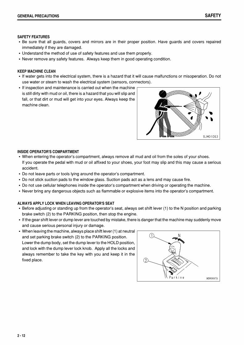
FIRE EXTINGUISHER AND FIRST AID KITAlways follow the precautions below to prepare for action if any injury or fire should occur.
Be sure that fire extinguishers have been provided and read thelabels to ensure that you know how to use them in emergencies.Carry out periodic inspection and maintenance to ensure thatthe fire extinguisher can always be used.Provide a first aid kit in the storage point. Carry out periodicchecks and add to the contents if necessary.
2 - 11
.
SAFETYGENERAL PRECAUTIONS
SAFETY FEATURESBe sure that all guards, covers and mirrors are in their proper position. Have guards and covers repairedimmediately if they are damaged.Understand the method of use of safety features and use them properly.Never remove any safety features. Always keep them in good operating condition.
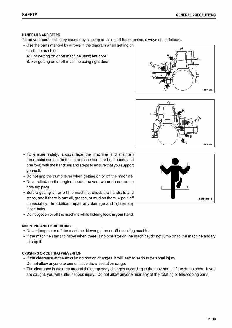
KEEP MACHINE CLEANIf water gets into the electrical system, there is a hazard that it will cause malfunctions or misoperation. Do notuse water or steam to wash the electrical system (sensors, connectors).If inspection and maintenance is carried out when the machineis still dirty with mud or oil, there is a hazard that you will slip andfall, or that dirt or mud will get into your eyes. Always keep themachine clean.
INSIDE OPERATOR'S COMPARTMENTWhen entering the operator's compartment, always remove all mud and oil from the soles of your shoes.If you operate the pedal with mud or oil affixed to your shoes, your foot may slip and this may cause a seriousaccident.Do not leave parts or tools lying around the operator's compartment.Do not stick suction pads to the window glass. Suction pads act as a lens and may cause fire.Do not use cellular telephones inside the operator's compartment when driving or operating the machine.Never bring any dangerous objects such as flammable or explosive items into the operator's compartment.
ALWAYS APPLY LOCK WHEN LEAVING OPERATOR'S SEATBefore adjusting or standing up from the operator's seat, always set shift lever (1) to the N position and parkingbrake switch (2) to the PARKING position, then stop the engine.If the gear shift lever or dump lever are touched by mistake, there is danger that the machine may suddenly moveand cause serious personal injury or damage.When leaving the machine, always place shift lever (1) at neutraland set parking brake switch (2) to the PARKING position.Lower the dump body, set the dump lever to the HOLD position,and lock with the dump lever lock knob. Apply all the locks andalways remember to take the key with you and keep it in thefixed place.
2 - 12
.
SAFETY GENERAL PRECAUTIONS
HANDRAILS AND STEPSTo prevent personal injury caused by slipping or falling off the machine, always do as follows.
Use the parts marked by arrows in the diagram when getting onor off the machine.A: For getting on or off machine using left doorB: For getting on or off machine using right door
To ensure safety, always face the machine and maintainthree-point contact (both feet and one hand, or both hands andone foot) with the handrails and steps to ensure that you supportyourself.Do not grip the dump lever when getting on or off the machine.Never climb on the engine hood or covers where there are nonon-slip pads.Before getting on or off the machine, check the handrails andsteps, and if there is any oil, grease, or mud on them, wipe it offimmediately. In addition, repair any damage and tighten anyloose bolts.Do not get on or off the machine while holding tools in your hand.
MOUNTING AND DISMOUNTINGNever jump on or off the machine. Never get on or off a moving machine.If the machine starts to move when there is no operator on the machine, do not jump on to the machine and tryto stop it.
CRUSHING OR CUTTING PREVENTIONIf the clearance at the articulating portion changes, it will lead to serious personal injury.Do not allow anyone to come inside the articulation range.The clearance in the area around the dump body changes according to the movement of the dump body. If youare caught, you will suffer serious injury. Do not allow anyone near any of the rotating or telescoping parts.
2 - 13
.
SAFETYGENERAL PRECAUTIONS
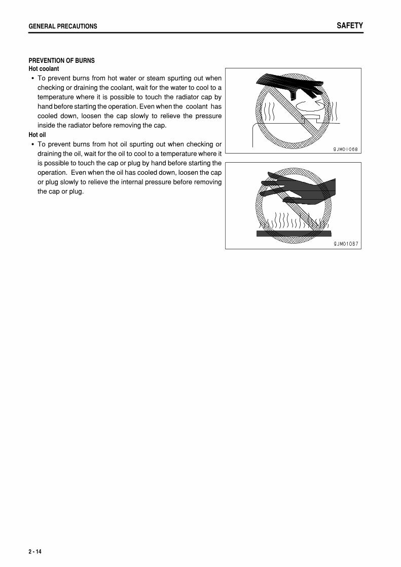
PREVENTION OF BURNSHot coolant
To prevent burns from hot water or steam spurting out whenchecking or draining the coolant, wait for the water to cool to atemperature where it is possible to touch the radiator cap byhand before starting the operation. Even when the coolant hascooled down, loosen the cap slowly to relieve the pressureinside the radiator before removing the cap.
Hot oilTo prevent burns from hot oil spurting out when checking ordraining the oil, wait for the oil to cool to a temperature where itis possible to touch the cap or plug by hand before starting theoperation. Even when the oil has cooled down, loosen the capor plug slowly to relieve the internal pressure before removingthe cap or plug.
2 - 14
.
SAFETY GENERAL PRECAUTIONS
FIRE PREVENTIONFire caused by fuel or oilFuel, oil, antifreeze, and window washer liquid are particularlyflammable and can be hazardous. To prevent fire, alwaysobserve the following:
Do not smoke or use any flame near fuel or oil.Stop the engine before refueling.Do not leave the machine while adding fuel or oil.Tighten all fuel and oil caps securely.Do not spill fuel on overheated surfaces or on parts of theelectrical system.Use well-ventilated areas for adding or storing oil and fuel.Keep oil and fuel in the determined place and do not allowunauthorized persons to enter.After adding fuel or oil, wipe up any spilled fuel or oil.When carrying out grinding or welding work on the chassis,move any flammable materials to a safe place beforestarting.When washing parts with oil, use a non-flammable oil. Dieseloil and gasoline may catch fire, so do not use them.Put greasy rags and other flammable materials into a safecontainer to maintain safety at the work place.Do not weld or use a cutting torch to cut any pipes or tubesthat contain flammable liquids.
Fire caused by accumulation of flammable material.Remove any dry leaves, chips, pieces of paper, dust, or any other flammable materials accumulated or affixedaround the engine, exhaust manifold, muffler, or battery, or inside the undercovers.
Fire coming from electric wiringShort circuits in the electrical system can cause fire.
Always keep electric wiring connections clean and securely tightened.Check the wiring every day for looseness or damage. Tighten any loose connectors or wiring clamps. Repairor replace any damaged wiring.
Fire coming from hydraulic lineCheck that all the hose and tube clamps, guards, and cushions are securely fixed in position.If they are loose, they may vibrate during operation and rub against other parts. This may lead to damage to thehoses, and cause high-pressure oil to spurt out, leading to fire damage or serious injury.
Explosion caused by lighting equipmentWhen checking fuel, oil, battery electrolyte, window washer fluid, or coolant, always use lighting withanti-explosion specifications. If such lighting equipment is not used, there is danger of explosion that maycause serious injury.When taking the electrical power for the lighting from the machine itself, follow the instructions in this manual.
ACTION IF FIRE OCCURSIf a fire occurs, escape from the machine as follows.
Turn the start switch OFF to stop the engine.Use the handrails and steps to get off the machine.
2 - 15
.
SAFETYGENERAL PRECAUTIONS
WINDOW WASHER LIQUIDUse an ethyl alcohol base washer liquid.Methyl alcohol base washer liquid may irritate your eyes, so do not use it.
PRECAUTIONS WHEN USING ROPS (Roll Over Protective Structure)The operator's cab has a ROPS structure. In addition to supportingof the load if the machine tips over, it also absorbs the impactenergy and protects the operator. If the function of ROPS isreduced, it cannot protect the operator and he may be injured.Always do the following.
Do not weld, drill holes, or make any other modification to theoperator's cab structure.Repair or replace the operator's cab if it is deformed by fallingobjects or when the machine tips over. For details of repair,please consult your Komatsu distributor.
Even when the ROPS is installed, if you do not fasten your seat beltsecurely, it cannot protect you properly. Always fasten your seatbelt when operating the machine.
PRECAUTIONS FOR ATTACHMENTS, OPTIONSWhen installing optional parts or attachments, there may be problems with safety or legal restrictions. Thereforecontact your Komatsu distributor for advice.Any injuries, accidents, product failures or other property damages resulting from the use of unauthorizedattachments or parts will not be the responsibility of Komatsu.Always read the instruction manual for the attachment.
UNAUTHORIZED MODIFICATIONIf this machine is modified without permission from Komatsu, there is danger that problems may occur with safetyand that this may lead to serious personal injury. Modifications may have an adverse effect on items such asmachine strength and visibility. Before making any modifications, please consult your Komatsu distributor.Komatsu cannot take any responsibility for accidents, failures, or damage caused by modifications not authorizedby Komatsu.
SAFETY AT WORKSITEBefore starting operations, thoroughly check the area for any unusual conditions that could be dangerous.
Check the terrain and condition of the ground at the worksite, and determine the safest method of operation. Donot operate where there is a hazard of landslides or falling rocks.Take necessary measures to prevent any unauthorized person from entering the operating area.When traveling or operating in shallow water or on soft ground, check the shape and condition of the bedrock, andthe depth and speed of flow of the water before starting operations.Always design and maintain the roads on the jobsite so that the machines can travel safely.
2 - 16
.
SAFETY GENERAL PRECAUTIONS
WORKING ON LOOSE GROUNDAvoid traveling or operating your machine too close to the edge of cliffs, overhangs, and deep ditches. Theground may be weak in such areas. If the ground should collapse under the weight or vibration of the machine,there is a hazard that the machine may fall or tip over. Remember that the soil after heavy rain or blasting or afterearthquakes is weak in these areas.When working on embankments or near excavated ditches, there is a hazard that the weight and vibration of themachine will cause the soil to collapse. Before starting operations, take steps to ensure that the ground is safeand to prevent the machine from rolling over or falling.
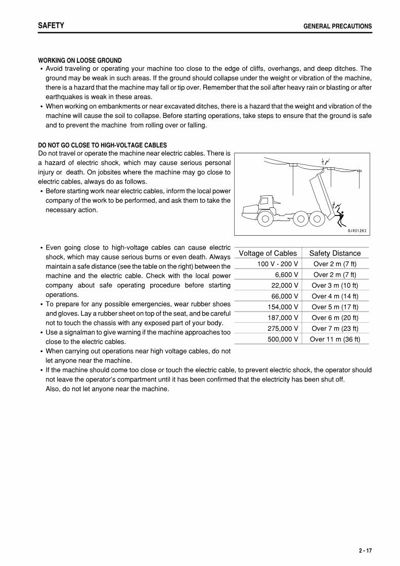
DO NOT GO CLOSE TO HIGH-VOLTAGE CABLESDo not travel or operate the machine near electric cables. There isa hazard of electric shock, which may cause serious personalinjury or death. On jobsites where the machine may go close toelectric cables, always do as follows.
Before starting work near electric cables, inform the local powercompany of the work to be performed, and ask them to take thenecessary action.
Voltage of Cables Safety Distance100 V - 200 V Over 2 m (7 ft)
6,600 V Over 2 m (7 ft)
22,000 V Over 3 m (10 ft)
66,000 V Over 4 m (14 ft)
154,000 V Over 5 m (17 ft)
187,000 V Over 6 m (20 ft)
275,000 V Over 7 m (23 ft)
500,000 V Over 11 m (36 ft)
Even going close to high-voltage cables can cause electricshock, which may cause serious burns or even death. Alwaysmaintain a safe distance (see the table on the right) between themachine and the electric cable. Check with the local powercompany about safe operating procedure before startingoperations.To prepare for any possible emergencies, wear rubber shoesand gloves. Lay a rubber sheet on top of the seat, and be carefulnot to touch the chassis with any exposed part of your body.Use a signalman to give warning if the machine approaches tooclose to the electric cables.When carrying out operations near high voltage cables, do notlet anyone near the machine.If the machine should come too close or touch the electric cable, to prevent electric shock, the operator shouldnot leave the operator's compartment until it has been confirmed that the electricity has been shut off.Also, do not let anyone near the machine.
2 - 17
.
SAFETYGENERAL PRECAUTIONS
ENSURE GOOD VISIBILITYThis machine is equipped with mirrors to improve the visibility, but even with mirrors, there are places, which cannotbe seen from the operator's seat, so always be careful when operating.When operating or traveling in places with poor visibility, if it is impossible to confirm the condition of the job side orobstacle is in the area around the machine, there is danger that the machine may suffer damage or the operator maysuffer serious personal injury. When operating or traveling in places with poor visibility, always observe the followingitems strictly.
If the visibility cannot be sufficiently assured, position a flagman if necessary. The operator should pay carefulattention to the signs and follow the instructions of the flagman. The signals should be given only by one flagman.When working in dark places, turn on the working lamps and front lamps of the machine, and if necessary, setup additional lighting in the area.Stop operations if there is poor visibility, such as in fog, snow, rain, or sand storms.Check the mirrors on the machine before starting operations every day. Clean off any dirt and adjust the viewto ensure good visibility.In areas where it is impossible to confirm the area behind the machine and observation cameras have been setup, clean off any dirt from the lens and make sure that the camera gives a clear view of the rear.
PRECAUTIONS RELATED TO VENTILATION OF EXHAUST GASThe engine exhaust gas contains substances that may damageyour health or even cause death. Start or operate the engine in aplace where there is good ventilation. If the engine or machinemust be operated inside a building or under ground, where theventilation is poor, take steps to ensure that the engine exhaustgas is removed and that ample fresh air is brought in.
CHECKING SIGNALMAN'S SIGNALS AND SIGNSSet up signs to inform of road shoulders and soft ground. If the visibility is not good, position a signalman ifnecessary. Operators should pay careful attention to the signs and follow the instructions from the signalman.Only one signalman should give signals.Make sure that all workers understand the meaning of all signals and signs before starting work.
EMERGENCY ESCAPE FROM OPERATOR'S CABThe cab installed on this machine has doors on the left and right sides. If the door on one side does not open,escape through the door on the other side.
2 - 18
.
SAFETY GENERAL PRECAUTIONS
ASBESTOS DUST HAZARD PREVENTIONAsbestos dust in the air can cause lung cancer if it is inhaled. Thereis danger of inhaling asbestos when working on jobsites handlingdemolition work or work handling industrial waste. Always observethe following.
Spray water to keep down the dust when cleaning. Do not usecompressed air for cleaning.If there is danger that there may be asbestos dust in the air,always operate the machine from an upwind position. Allworkers should use an approved respirator.Do not allow other persons to approach during the operation.Always observe the rules and regulations for the work site and environmental standards.
This machine does not use asbestos, but there is a danger that imitation parts may contain asbestos, so always usegenuine Komatsu parts.
2 - 19
.
SAFETYPRECAUTIONS DURING OPERATION
PRECAUTIONS DURING OPERATION
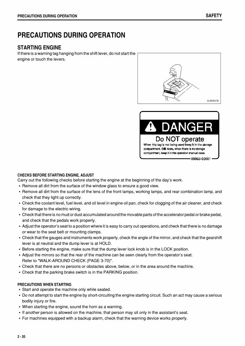
STARTING ENGINEIf there is a warning tag hanging from the shift lever, do not start theengine or touch the levers.
CHECKS BEFORE STARTING ENGINE, ADJUSTCarry out the following checks before starting the engine at the beginning of the day's work.
Remove all dirt from the surface of the window glass to ensure a good view.Remove all dirt from the surface of the lens of the front lamps, working lamps, and rear combination lamp, andcheck that they light up correctly.Check the coolant level, fuel level, and oil level in engine oil pan, check for clogging of the air cleaner, and checkfor damage to the electric wiring.Check that there is no mud or dust accumulated around the movable parts of the accelerator pedal or brake pedal,and check that the pedals work properly.Adjust the operator's seat to a position where it is easy to carry out operations, and check that there is no damageor wear to the seat belt or mounting clamps.Check that the gauges and instruments work properly, check the angle of the mirror, and check that the gearshiftlever is at neutral and the dump lever is at HOLD.Before starting the engine, make sure that the dump lever lock knob is in the LOCK position.Adjust the mirrors so that the rear of the machine can be seen clearly from the operator's seat.Refer to "WALK-AROUND CHECK (PAGE 3-70)".Check that there are no persons or obstacles above, below, or in the area around the machine.Check that the parking brake switch is in the PARKING position.
PRECAUTIONS WHEN STARTINGStart and operate the machine only while seated.Do not attempt to start the engine by short-circuiting the engine starting circuit. Such an act may cause a seriousbodily injury or fire.When starting the engine, sound the horn as a warning.If another person is allowed on the machine, that person may sit only in the assistant's seat.For machines equipped with a backup alarm, check that the warning device works properly.
2 - 20

.
SAFETY PRECAUTIONS DURING OPERATION
PRECAUTIONS IN COLD AREASCarry out the warming-up operation thoroughly. If the machine is not thoroughly warmed up before the gear shiftlever or dump lever are operated, the reaction of the machine will be slow or may change suddenly, and this maycause an accident.If the battery electrolyte is frozen, do not charge the battery or start the engine with a different power source.There is a hazard that this will ignite the battery and cause the battery to explode.Before charging or starting the engine with a different power source, melt the battery electrolyte and check thatthere is no leakage of electrolyte before starting.
2 - 21
.
SAFETYPRECAUTIONS DURING OPERATION
OPERATION
CHECKS BEFORE STARTING OPERATIONWhen carrying out the checks, move the machine to a wide area where there are no obstructions, and operateslowly. Do not allow anyone near the machine.
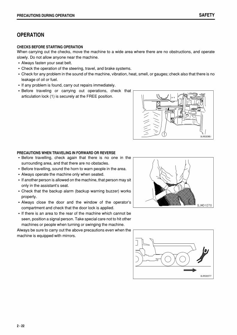
Always fasten your seat belt.Check the operation of the steering, travel, and brake systems.Check for any problem in the sound of the machine, vibration, heat, smell, or gauges; check also that there is noleakage of oil or fuel.If any problem is found, carry out repairs immediately.Before traveling or carrying out operations, check thatarticulation lock (1) is securely at the FREE position.
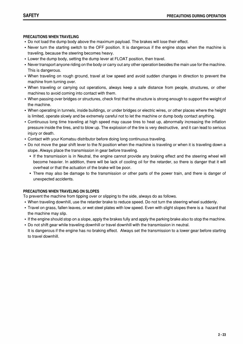
PRECAUTIONS WHEN TRAVELING IN FORWARD OR REVERSEBefore travelling, check again that there is no one in thesurrounding area, and that there are no obstacles.Before travelling, sound the horn to warn people in the area.Always operate the machine only when seated.If another person is allowed on the machine, that person may sitonly in the assistant's seat.Check that the backup alarm (backup warning buzzer) worksproperly.Always close the door and the window of the operator'scompartment and check that the door lock is applied.If there is an area to the rear of the machine which cannot beseen, position a signal person. Take special care not to hit othermachines or people when turning or swinging the machine.
Always be sure to carry out the above precautions even when themachine is equipped with mirrors.
2 - 22
.
SAFETY PRECAUTIONS DURING OPERATION
PRECAUTIONS WHEN TRAVELINGDo not load the dump body above the maximum payload. The brakes will lose their effect.Never turn the starting switch to the OFF position. It is dangerous if the engine stops when the machine istraveling, because the steering becomes heavy.Lower the dump body, setting the dump lever at FLOAT position, then travel.Never transport anyone riding on the body or carry out any other operation besides the main use for the machine.This is dangerous.When traveling on rough ground, travel at low speed and avoid sudden changes in direction to prevent themachine from turning over.When traveling or carrying out operations, always keep a safe distance from people, structures, or othermachines to avoid coming into contact with them.When passing over bridges or structures, check first that the structure is strong enough to support the weight ofthe machine.When operating in tunnels, inside buildings, or under bridges or electric wires, or other places where the heightis limited, operate slowly and be extremely careful not to let the machine or dump body contact anything.Continuous long time traveling at high speed may cause tires to heat up, abnormally increasing the inflationpressure inside the tires, and to blow up. The explosion of the tire is very destructive, and it can lead to seriousinjury or death.Contact with your Komatsu distributor before doing long continuous traveling.Do not move the gear shift lever to the N position when the machine is traveling or when it is traveling down aslope. Always place the transmission in gear before traveling.
If the transmission is in Neutral, the engine cannot provide any braking effect and the steering wheel willbecome heavier. In addition, there will be lack of cooling oil for the retarder, so there is danger that it willoverheat or that the actuation of the brake will be poor.There may also be damage to the transmission or other parts of the power train, and there is danger ofunexpected accidents.
PRECAUTIONS WHEN TRAVELING ON SLOPESTo prevent the machine from tipping over or slipping to the side, always do as follows.
When traveling downhill, use the retarder brake to reduce speed. Do not turn the steering wheel suddenly.Travel on grass, fallen leaves, or wet steel plates with low speed. Even with slight slopes there is a hazard thatthe machine may slip.If the engine should stop on a slope, apply the brakes fully and apply the parking brake also to stop the machine.Do not shift gear while traveling downhill or travel downhill with the transmission in neutral. It is dangerous if the engine has no braking effect. Always set the transmission to a lower gear before startingto travel downhill.
2 - 23
.
SAFETYPRECAUTIONS DURING OPERATION
PRECAUTIONS WHEN OPERATING DUMP BODYBefore starting the dumping operation, check to be sure there is no person or object behind the machine.Stop the machine in the correct position, and check again that there is no person or object behind the machine.Give the determined signal, then slowly operate the dump body.If necessary, use blocks for the wheels or position a flagman.Do not carry out dumping operations on slopes. The machine stability will become poor and there is the dangerthat it could tip over.Do not travel with the body raised.Do not leave or return to the operator's seat during loading work.When carrying out dumping operations, set the machine facing straight forward. If dumping operations arecarried out with the machine articulated, the stability of the machine will be reduced and there is danger that it maytip over.When the dump body is raised, the center of gravity of the machine moves continuously. At this time, if the groundis soft, the stability of the machine changes. Take care.Take care particularly when dumping sticky material (wet clay, frozen material, etc.) on a soft ground. The stabilityof the machine is reduced and there is danger that it may tip over.
PRECAUTIONS WHEN OPERATINGWhen using the machine, to prevent the machine from overturning due to overloading and to avoid damage to thedump body, do not exceed the performance or maximum load specified for the machine structure.When operating in tunnels, or under bridges or electric wires, or in other places where the height is limited,operate slowly and be extremely careful not to let the dump body contact anything.To prevent accidents caused by hitting other objects, always operate the machine at a speed which is safe foroperation, particular in confined spaces, indoors, and in places where there are other machines.
PRECAUTIONS FOR ACCUMULATED SNOW, ICESnow-covered or frozen surfaces are slippery, so be extremely careful when traveling or operating the machine,and do not operate the levers suddenly. Even a slight slope may cause the machine to slip, so be particularlycareful when working on slopes.With frozen ground surfaces, the ground becomes soft when the temperature rises, and this may cause themachine to tip over or make it impossible for the machine to escape.If the machine enters deep snow, there is a hazard that it may tip over or become buried in the snow. Be carefulnot to leave the road shoulder or to get trapped in a snow drift.When traveling on snow-covered roads, always fit tire chains.When traveling on snow-covered roads, never use the foot brake to make sudden stops. Shift down to use theengine brake and carry out double braking (depress the brake pedal several times) to stop the machine.When the loaded materials in the dump body are frozen, do not dump. There is a danger that the machine couldtip over.
2 - 24
.
SAFETY PRECAUTIONS DURING OPERATION
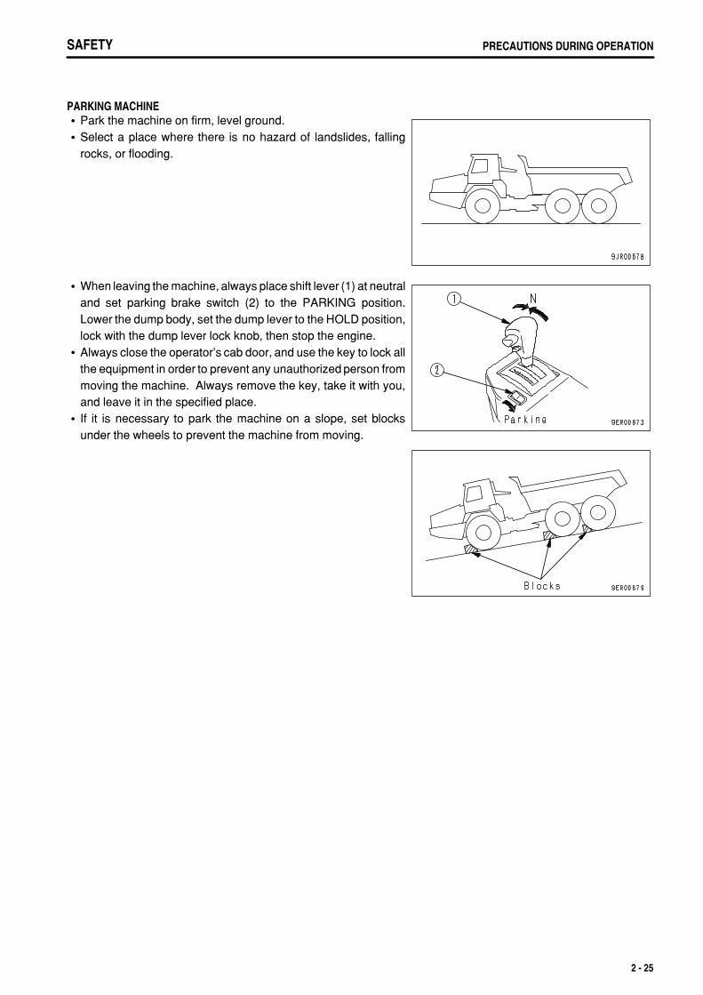
PARKING MACHINEPark the machine on firm, level ground.Select a place where there is no hazard of landslides, fallingrocks, or flooding.
When leaving the machine, always place shift lever (1) at neutraland set parking brake switch (2) to the PARKING position.Lower the dump body, set the dump lever to the HOLD position,lock with the dump lever lock knob, then stop the engine.Always close the operator's cab door, and use the key to lock allthe equipment in order to prevent any unauthorized person frommoving the machine. Always remove the key, take it with you,and leave it in the specified place.If it is necessary to park the machine on a slope, set blocksunder the wheels to prevent the machine from moving.
2 - 25
.
SAFETYPRECAUTIONS DURING OPERATION
TRANSPORTATIONThis machine must be disassembled for transportation. When transporting the machine, please consult yourKomatsu distributor.
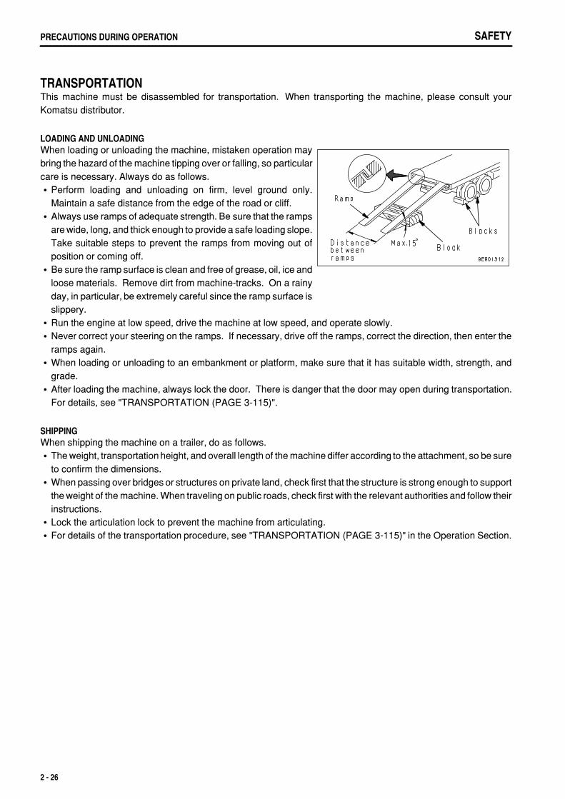
LOADING AND UNLOADINGWhen loading or unloading the machine, mistaken operation maybring the hazard of the machine tipping over or falling, so particularcare is necessary. Always do as follows.
Perform loading and unloading on firm, level ground only.Maintain a safe distance from the edge of the road or cliff.Always use ramps of adequate strength. Be sure that the rampsare wide, long, and thick enough to provide a safe loading slope.Take suitable steps to prevent the ramps from moving out ofposition or coming off.Be sure the ramp surface is clean and free of grease, oil, ice andloose materials. Remove dirt from machine-tracks. On a rainyday, in particular, be extremely careful since the ramp surface isslippery.Run the engine at low speed, drive the machine at low speed, and operate slowly.Never correct your steering on the ramps. If necessary, drive off the ramps, correct the direction, then enter theramps again.When loading or unloading to an embankment or platform, make sure that it has suitable width, strength, andgrade.After loading the machine, always lock the door. There is danger that the door may open during transportation.For details, see "TRANSPORTATION (PAGE 3-115)".
SHIPPINGWhen shipping the machine on a trailer, do as follows.
The weight, transportation height, and overall length of the machine differ according to the attachment, so be sureto confirm the dimensions.When passing over bridges or structures on private land, check first that the structure is strong enough to supportthe weight of the machine. When traveling on public roads, check first with the relevant authorities and follow theirinstructions.Lock the articulation lock to prevent the machine from articulating.For details of the transportation procedure, see "TRANSPORTATION (PAGE 3-115)" in the Operation Section.
2 - 26
.
SAFETY PRECAUTIONS DURING OPERATION
BATTERY
BATTERY HAZARD PREVENTIONBattery electrolyte contains sulphuric acid, and batteries generate flammable hydrogen gas, which may explode.Mistaken handling can lead to serious injury or fire. For this reason, always observe the following precautions.
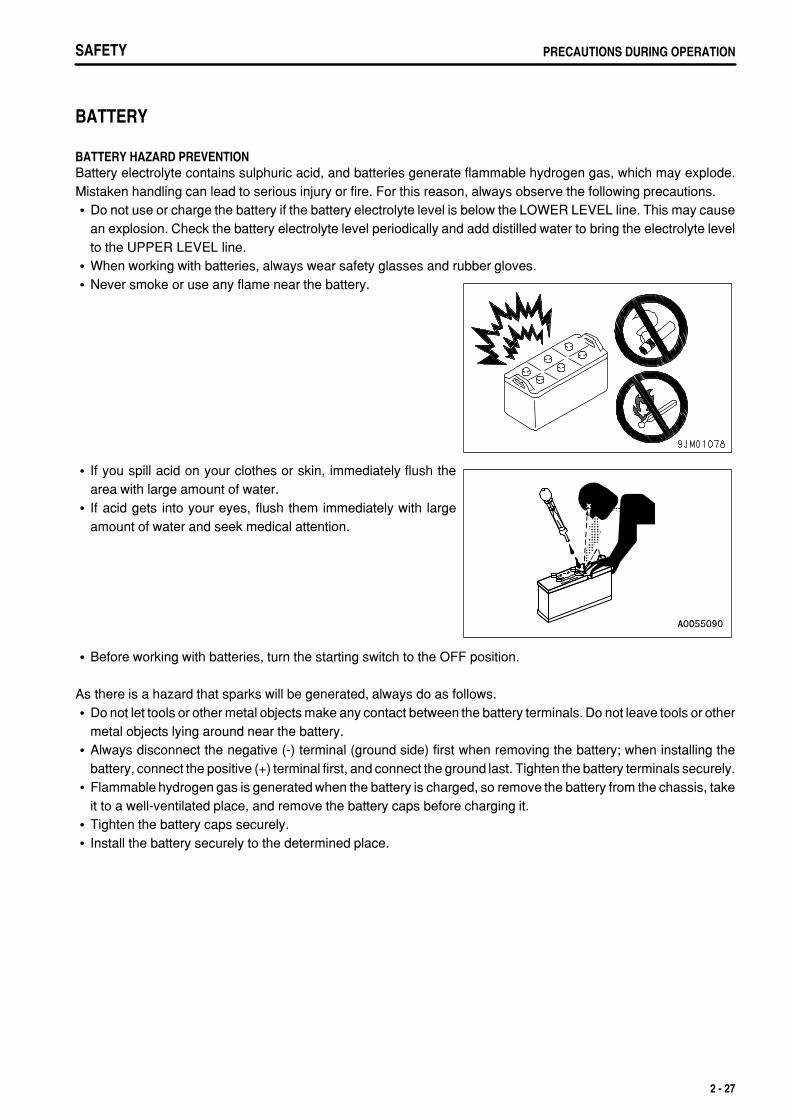
Do not use or charge the battery if the battery electrolyte level is below the LOWER LEVEL line. This may causean explosion. Check the battery electrolyte level periodically and add distilled water to bring the electrolyte levelto the UPPER LEVEL line.When working with batteries, always wear safety glasses and rubber gloves.Never smoke or use any flame near the battery.
If you spill acid on your clothes or skin, immediately flush thearea with large amount of water.If acid gets into your eyes, flush them immediately with largeamount of water and seek medical attention.
Before working with batteries, turn the starting switch to the OFF position.
As there is a hazard that sparks will be generated, always do as follows.Do not let tools or other metal objects make any contact between the battery terminals. Do not leave tools or othermetal objects lying around near the battery.Always disconnect the negative (-) terminal (ground side) first when removing the battery; when installing thebattery, connect the positive (+) terminal first, and connect the ground last. Tighten the battery terminals securely.Flammable hydrogen gas is generated when the battery is charged, so remove the battery from the chassis, takeit to a well-ventilated place, and remove the battery caps before charging it.Tighten the battery caps securely.Install the battery securely to the determined place.
2 - 27
.
SAFETYPRECAUTIONS DURING OPERATION
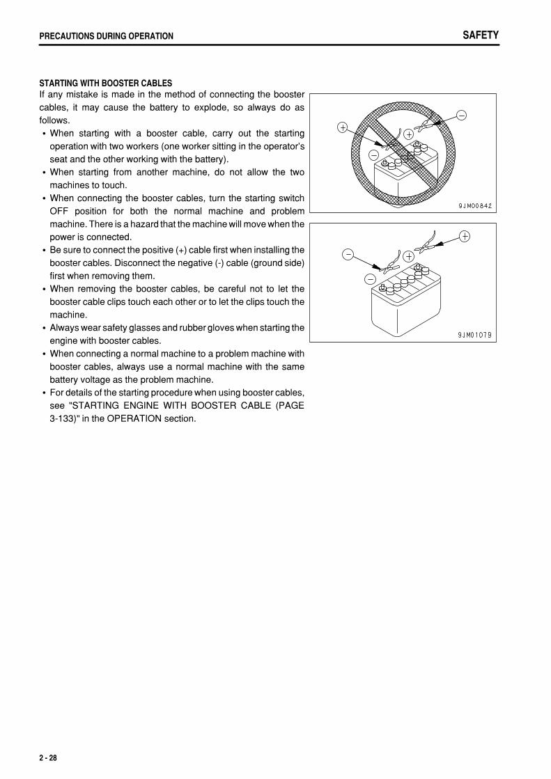
STARTING WITH BOOSTER CABLESIf any mistake is made in the method of connecting the boostercables, it may cause the battery to explode, so always do asfollows.
When starting with a booster cable, carry out the startingoperation with two workers (one worker sitting in the operator'sseat and the other working with the battery).When starting from another machine, do not allow the twomachines to touch.When connecting the booster cables, turn the starting switchOFF position for both the normal machine and problemmachine. There is a hazard that the machine will move when thepower is connected.Be sure to connect the positive (+) cable first when installing thebooster cables. Disconnect the negative (-) cable (ground side)first when removing them.When removing the booster cables, be careful not to let thebooster cable clips touch each other or to let the clips touch themachine.Always wear safety glasses and rubber gloves when starting theengine with booster cables.When connecting a normal machine to a problem machine withbooster cables, always use a normal machine with the samebattery voltage as the problem machine.For details of the starting procedure when using booster cables,see "STARTING ENGINE WITH BOOSTER CABLE (PAGE3-133)" in the OPERATION section.
2 - 28
.
SAFETY PRECAUTIONS DURING OPERATION
TOWING
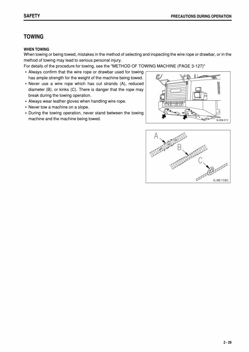
WHEN TOWINGWhen towing or being towed, mistakes in the method of selecting and inspecting the wire rope or drawbar, or in themethod of towing may lead to serious personal injury.For details of the procedure for towing, see the "METHOD OF TOWING MACHINE (PAGE 3-127)"
Always confirm that the wire rope or drawbar used for towinghas ample strength for the weight of the machine being towed.Never use a wire rope which has cut strands (A), reduceddiameter (B), or kinks (C). There is danger that the rope maybreak during the towing operation.Always wear leather gloves when handling wire rope.Never tow a machine on a slope.During the towing operation, never stand between the towingmachine and the machine being towed.
2 - 29
.
SAFETYPRECAUTIONS FOR MAINTENANCE
PRECAUTIONS FOR MAINTENANCE
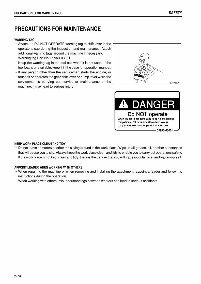
WARNING TAGAttach the DO NOT OPERATE warning tag to shift lever in theoperator's cab during the inspection and maintenance. Attachadditional warning tags around the machine if necessary.Warning tag Part No. 09963-03001Keep the warning tag in the tool box when it is not used. If thetool box is unavailable, keep it in the case for operation manual.If any person other than the serviceman starts the engine, ortouches or operates the gear shift lever or dump lever while theserviceman is carrying out service or maintenance of themachine, it may lead to serious injury.
KEEP WORK PLACE CLEAN AND TIDYDo not leave hammers or other tools lying around in the work place. Wipe up all grease, oil, or other substancesthat will cause you to slip. Always keep the work place clean and tidy to enable you to carry out operations safely.If the work place is not kept claen and tidy, there is the danger that you will trip, slip, or fall over and injure yourself.
APPOINT LEADER WHEN WORKING WITH OTHERSWhen repairing the machine or when removing and installing the attachment, appoint a leader and follow hisinstructions during the operation.When working with others, misunderstandings between workers can lead to serious accidents.
2 - 30
.
SAFETY PRECAUTIONS FOR MAINTENANCE
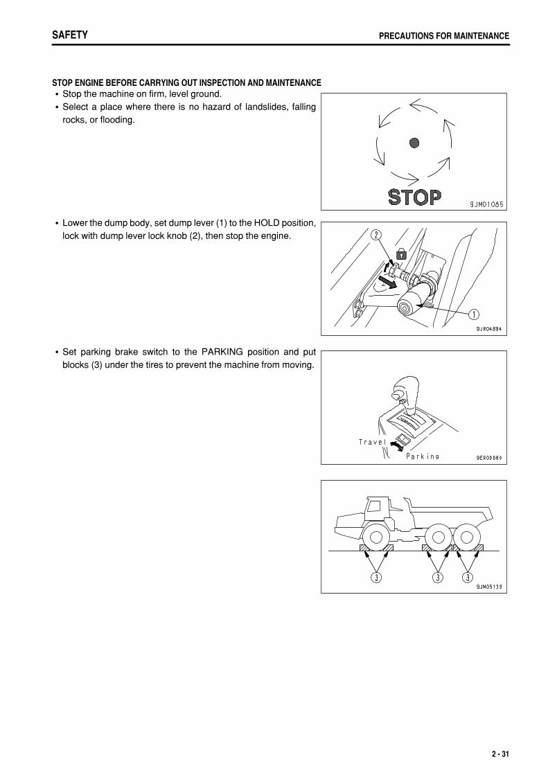
STOP ENGINE BEFORE CARRYING OUT INSPECTION AND MAINTENANCEStop the machine on firm, level ground.Select a place where there is no hazard of landslides, fallingrocks, or flooding.
Lower the dump body, set dump lever (1) to the HOLD position,lock with dump lever lock knob (2), then stop the engine.
Set parking brake switch to the PARKING position and putblocks (3) under the tires to prevent the machine from moving.
2 - 31
.
SAFETYPRECAUTIONS FOR MAINTENANCE SAFETYPRECAUTIONS FOR MAINTENANCE
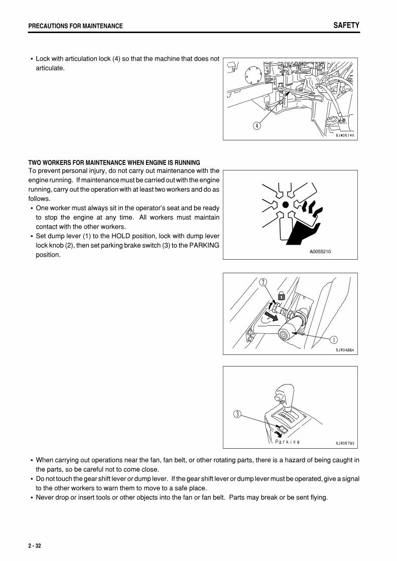
Lock with articulation lock (4) so that the machine that does notarticulate.
TWO WORKERS FOR MAINTENANCE WHEN ENGINE IS RUNNINGTo prevent personal injury, do not carry out maintenance with theengine running. If maintenancemust be carried out with the enginerunning, carry out the operation with at least two workers and do asfollows.
One worker must always sit in the operator's seat and be readyto stop the engine at any time. All workers must maintaincontact with the other workers.Set dump lever (1) to the HOLD position, lock with dump leverlock knob (2), then set parking brake switch (3) to the PARKINGposition.
When carrying out operations near the fan, fan belt, or other rotating parts, there is a hazard of being caught inthe parts, so be careful not to come close.Do not touch the gear shift lever or dump lever. If the gear shift lever or dump lever must be operated, give a signalto the other workers to warn them to move to a safe place.Never drop or insert tools or other objects into the fan or fan belt. Parts may break or be sent flying.
2 - 32
.
SAFETY PRECAUTIONS FOR MAINTENANCE
PROPER TOOLSUse only tools suited to the task and be sure to use the toolscorrectly. Using damaged, low quality, faulty, makeshift tools orimproper use of the tools could cause serious personal injury.
HANDLING SUSPENSION CYLINDER, ACCUMULATORThe suspension cylinders and accumulator are charged with high-pressure nitrogen gas. If any mistake is made inhandling, it may cause serious personal injury. To prevent this, always follow the procedure below.
Do not remove or disassemble the cylinder.Do not bring it near flame or dispose of it in fire.Do not make holes in it, weld it, or use a cutting torch.Do not bear any shock by hammering, rolling or similar activity.Ask for your Komatsu distributor when sealing gas into the cylinder or releasing gas from it.
PERSONNELDo not allow any unauthorized personnel into the area when servicing the machine. If necessary, employ a guard.
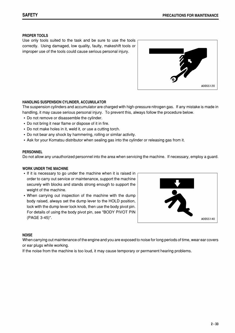
WORK UNDER THE MACHINEIf it is necessary to go under the machine when it is raised inorder to carry out service or maintenance, support the machinesecurely with blocks and stands strong enough to support theweight of the machine.When carrying out inspection of the machine with the dumpbody raised, always set the dump lever to the HOLD position,lock with the dump lever lock knob, then use the body pivot pin.For details of using the body pivot pin, see "BODY PIVOT PIN(PAGE 3-45)".
NOISEWhen carrying out maintenance of the engine and you are exposed to noise for long periods of time, wear ear coversor ear plugs while working.If the noise from the machine is too loud, it may cause temporary or permanent hearing problems.
2 - 33
.
SAFETYPRECAUTIONS FOR MAINTENANCE
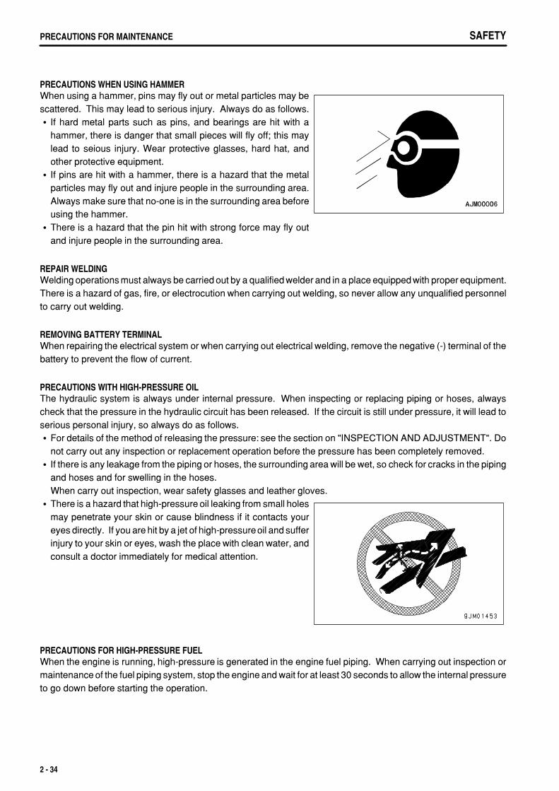
PRECAUTIONS WHEN USING HAMMERWhen using a hammer, pins may fly out or metal particles may bescattered. This may lead to serious injury. Always do as follows.
If hard metal parts such as pins, and bearings are hit with ahammer, there is danger that small pieces will fly off; this maylead to seious injury. Wear protective glasses, hard hat, andother protective equipment.If pins are hit with a hammer, there is a hazard that the metalparticles may fly out and injure people in the surrounding area.Always make sure that no-one is in the surrounding area beforeusing the hammer.There is a hazard that the pin hit with strong force may fly outand injure people in the surrounding area.
REPAIR WELDINGWelding operations must always be carried out by a qualified welder and in a place equipped with proper equipment.There is a hazard of gas, fire, or electrocution when carrying out welding, so never allow any unqualified personnelto carry out welding.
REMOVING BATTERY TERMINALWhen repairing the electrical system or when carrying out electrical welding, remove the negative (-) terminal of thebattery to prevent the flow of current.
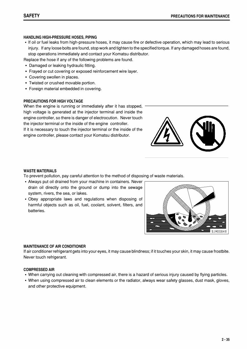
PRECAUTIONS WITH HIGH-PRESSURE OILThe hydraulic system is always under internal pressure. When inspecting or replacing piping or hoses, alwayscheck that the pressure in the hydraulic circuit has been released. If the circuit is still under pressure, it will lead toserious personal injury, so always do as follows.
For details of the method of releasing the pressure: see the section on "INSPECTION AND ADJUSTMENT". Donot carry out any inspection or replacement operation before the pressure has been completely removed.If there is any leakage from the piping or hoses, the surrounding area will be wet, so check for cracks in the pipingand hoses and for swelling in the hoses.When carry out inspection, wear safety glasses and leather gloves.There is a hazard that high-pressure oil leaking from small holesmay penetrate your skin or cause blindness if it contacts youreyes directly. If you are hit by a jet of high-pressureoil and sufferinjury to your skin or eyes, wash the place with clean water, andconsult a doctor immediately for medical attention.
PRECAUTIONS FOR HIGH-PRESSURE FUELWhen the engine is running, high-pressure is generated in the engine fuel piping. When carrying out inspection ormaintenance of the fuel piping system, stop the engine and wait for at least 30 seconds to allow the internal pressureto go down before starting the operation.
2 - 34
.
SAFETY PRECAUTIONS FOR MAINTENANCE
HANDLING HIGH-PRESSURE HOSES, PIPINGIf oil or fuel leaks from high-pressure hoses, it may cause fire or defective operation, which may lead to seriousinjury. If any loose bolts are found, stop work and tighten to the specified torque. If any damaged hoses are found,stop operations immediately and contact your Komatsu distributor.
Replace the hose if any of the following problems are found.Damaged or leaking hydraulic fitting.Frayed or cut covering or exposed reinforcement wire layer.Covering swollen in places.Twisted or crushed movable portion.Foreign material embedded in covering.
PRECAUTIONS FOR HIGH VOLTAGEWhen the engine is running or immediately after it has stopped,high voltage is generated at the injector terminal and inside theengine controller, so there is danger of electrocution. Never touchthe injector terminal or the inside of the engine controller.If it is necessary to touch the injector terminal or the inside of theengine controller, please contact your Komatsu distributor.
WASTE MATERIALSTo prevent pollution, pay careful attention to the method of disposing of waste materials.
Always put oil drained from your machine in containers. Neverdrain oil directly onto the ground or dump into the sewagesystem, rivers, the sea, or lakes.Obey appropriate laws and regulations when disposing ofharmful objects such as oil, fuel, coolant, solvent, filters, andbatteries.
MAINTENANCE OF AIR CONDITIONERIf air conditioner refrigerant gets into your eyes, it may cause blindness; if it touches your skin, it may cause frostbite.Never touch refrigerant.
COMPRESSED AIRWhen carrying out cleaning with compressed air, there is a hazard of serious injury caused by flying particles.When using compressed air to clean elements or the radiator, always wear safety glasses, dust mask, gloves,and other protective equipment.
2 - 35
.
SAFETYPRECAUTIONS FOR MAINTENANCE
PERIODIC REPLACEMENT OF SAFETY-CRITICAL PARTSIn order for the machine to be operated safely for a long time, it is necessary to add oil and to carry out serviceand maintenance at periodic intervals. In order to further increase safety, components with a strong relationshipto safety, such as hoses and seat belts, must be replaced at periodic intervals.Replacement of safety-critical parts: See "PERIODIC REPLACEMENT OF SAFETY CRITICAL PARTS (PAGE
4-15)".The material of these components naturally changes over time, and repeated use causes deterioration, wear, andfatigue. As a result, there is a hazard that these components may fail and cause serious injury or death. It isdifficult to judge the remaining life of these components from external inspection or the feeling when operating,so always replace them at the specified interval.Replace or repair safety-critical parts if any defect is found, even when they have not reached the specifiedreplacement time.
2 - 36
.
SAFETY PRECAUTIONS WITH TIRES
PRECAUTIONS WITH TIRES
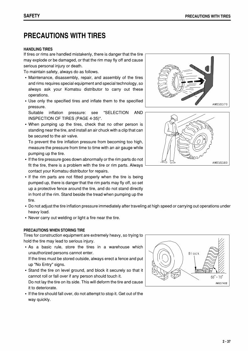
HANDLING TIRESIf tires or rims are handled mistakenly, there is danger that the tiremay explode or be damaged, or that the rim may fly off and causeserious personal injury or death.To maintain safety, always do as follows.
Maintenance, disassembly, repair, and assembly of the tiresand rims requires special equipment and special technology, soalways ask your Komatsu distributor to carry out theseoperations.Use only the specified tires and inflate them to the specifiedpressure.Suitable inflation pressure: see "SELECTION ANDINSPECTION OF TIRES (PAGE 4-35)".When pumping up the tires, check that no other person isstanding near the tire, and install an air chuck with a clip that canbe secured to the air valve.To prevent the tire inflation pressure from becoming too high,measure the pressure from time to time with an air gauge whilepumping up the tire.If the tire pressure goes down abnormally or the rim parts do notfit the tire, there is a problem with the tire or rim parts. Alwayscontact your Komatsu distributor for repairs.If the rim parts are not fitted properly when the tire is beingpumped up, there is danger that the rim parts may fly off, so setup a protective fence around the tire, and do not stand directlyin front of the rim. Stand beside the tread when pumping up thetire.Do not adjust the tire inflation pressure immediately after traveling at high speed or carrying out operations underheavy load.Never carry out welding or light a fire near the tire.
PRECAUTIONS WHEN STORING TIRETires for construction equipment are extremely heavy, so trying tohold the tire may lead to serious injury.
As a basic rule, store the tires in a warehouse whichunauthorized persons cannot enter.If the tires must be stored outside, always erect a fence and putup "No Entry" signs.Stand the tire on level ground, and block it securely so that itcannot roll or fall over if any person should touch it.Do not lay the tire on its side. This will deform the tire and causeit to deteriorate.If the tire should fall over, do not attempt to stop it. Get out of theway quickly.
2 - 37

.

.
3 - 1
.
OPERATIONGENERAL VIEW
GENERAL VIEW
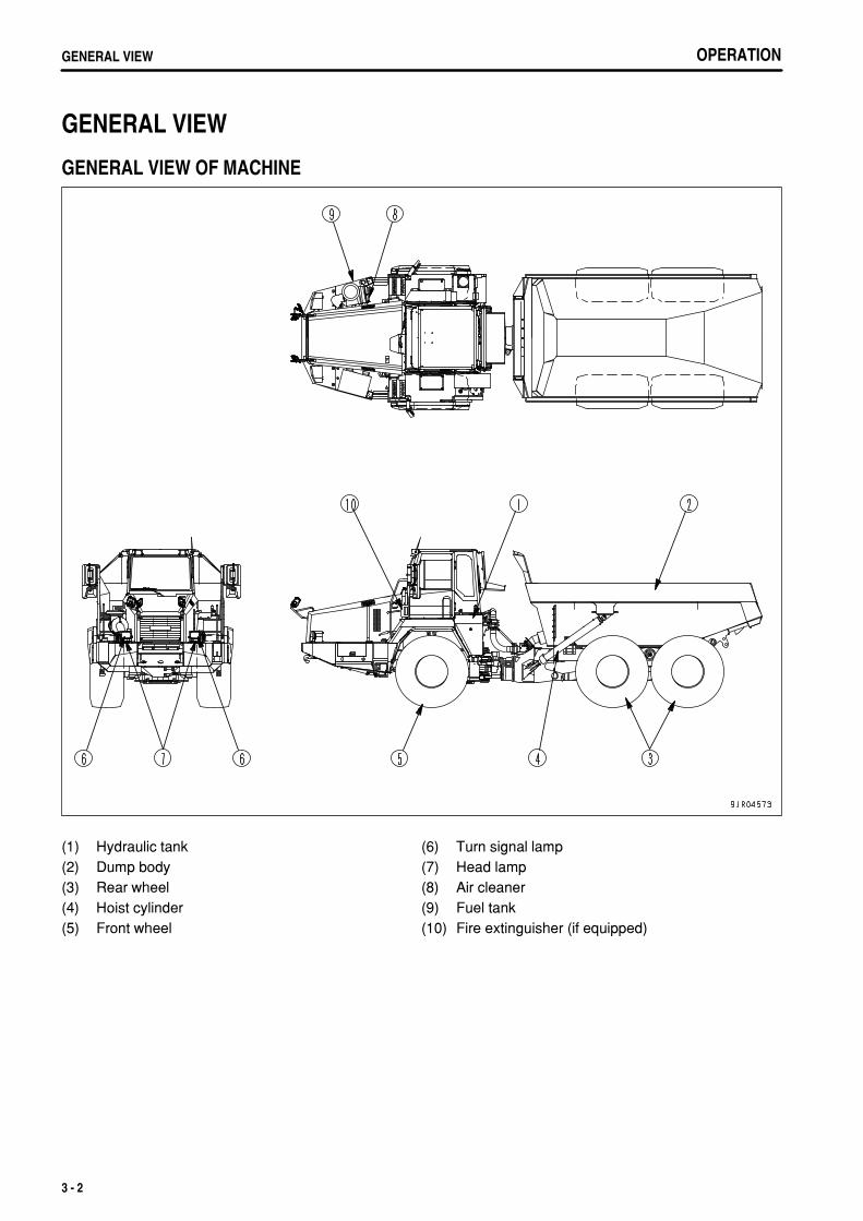
GENERAL VIEW OF MACHINE
(1)(2)(3)(4)(5)
Hydraulic tankDump bodyRear wheelHoist cylinderFront wheel
(6)(7)(8)(9)(10)
Turn signal lampHead lampAir cleanerFuel tankFire extinguisher (if equipped)
3 - 2
.
OPERATION GENERAL VIEW
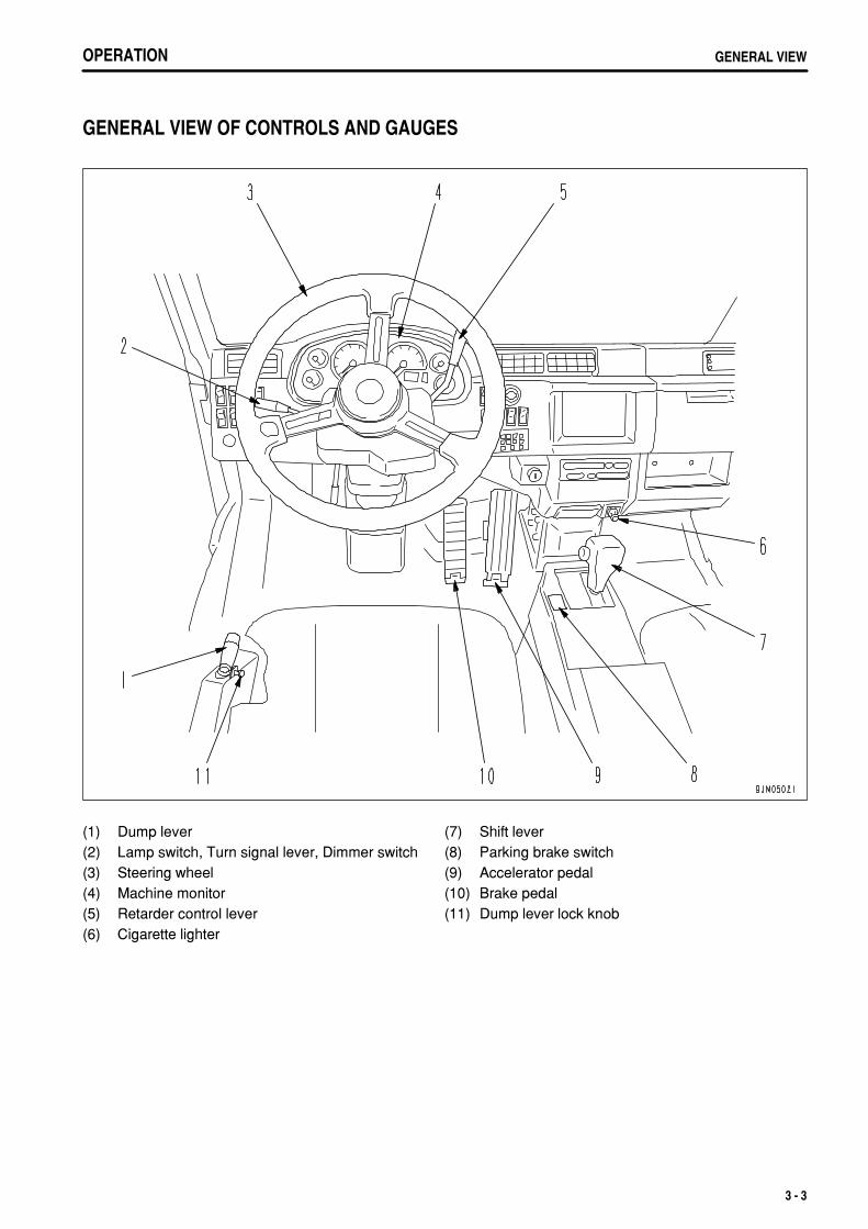
GENERAL VIEW OF CONTROLS AND GAUGES
(1)(2)(3)(4)(5)(6)
Dump leverLamp switch, Turn signal lever, Dimmer switchSteering wheelMachine monitorRetarder control leverCigarette lighter
(7)(8)(9)(10)(11)
Shift leverParking brake switchAccelerator pedalBrake pedalDump lever lock knob
3 - 3
.
OPERATIONGENERAL VIEW
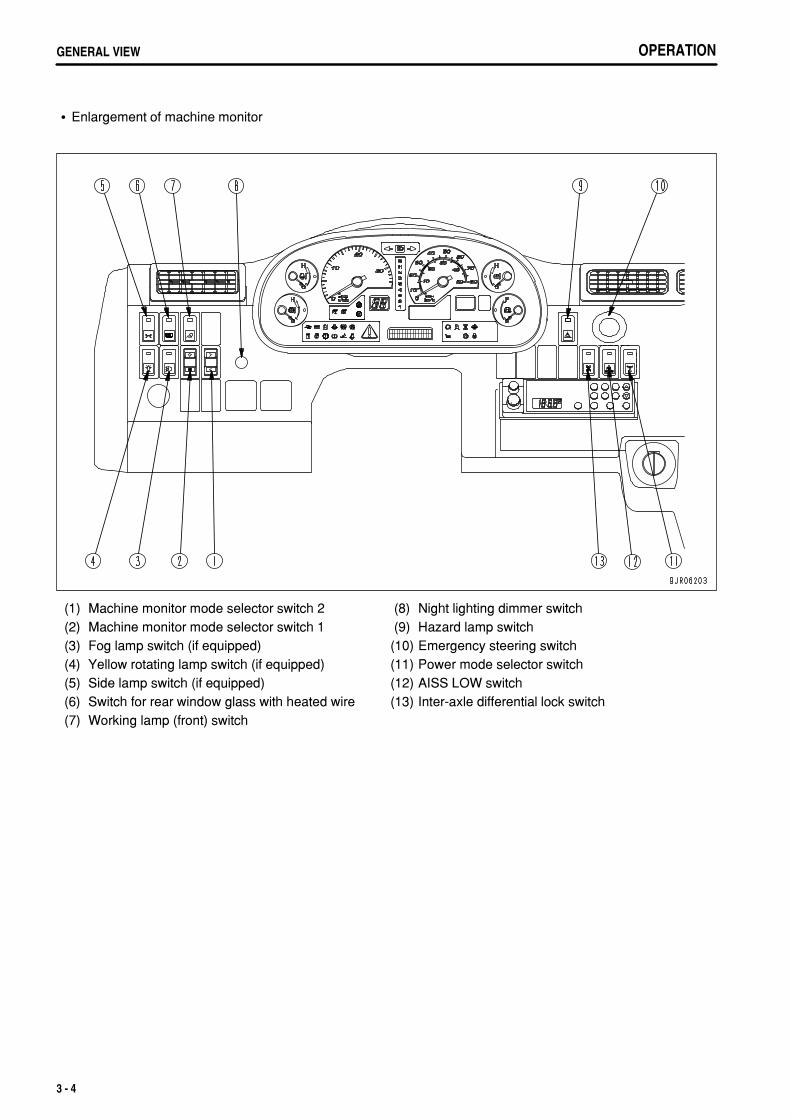
Enlargement of machine monitor
(1)(2)(3)(4)(5)(6)(7)
Machine monitor mode selector switch 2Machine monitor mode selector switch 1Fog lamp switch (if equipped)Yellow rotating lamp switch (if equipped)Side lamp switch (if equipped)Switch for rear window glass with heated wireWorking lamp (front) switch
(8)(9)
(10)(11)(12)(13)
Night lighting dimmer switchHazard lamp switchEmergency steering switchPower mode selector switchAISS LOW switchInter-axle differential lock switch
3 - 4
.
OPERATION EXPLANATION OF COMPONENTS
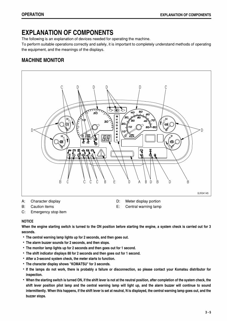
EXPLANATION OF COMPONENTSThe following is an explanation of devices needed for operating the machine.To perform suitable operations correctly and safely, it is important to completely understand methods of operatingthe equipment, and the meanings of the displays.
MACHINE MONITOR
A:B:C:
Character displayCaution itemsEmergency stop item
D:E:
Meter display portionCentral warning lamp
NOTICEWhen the engine starting switch is turned to the ON position before starting the engine, a system check is carried out for 3seconds.
The central warning lamp lights up for 2 seconds, and then goes out.The alarm buzzer sounds for 2 seconds, and then stops.The monitor lamp lights up for 2 seconds and then goes out for 1 second.The shift indicator displays 88 for 2 seconds and then goes out for 1 second.After a 3-second system check, the meter starts to function.The character display shows "KOMATSU" for 3 seconds.If the lamps do not work, there is probably a failure or disconnection, so please contact your Komatsu distributor forinspection.When the starting switch is turned ON, if the shift lever is not at the neutral position, after completion of the system check, theshift lever position pilot lamp and the central warning lamp will light up, and the alarm buzzer will continue to soundintermittently. When this happens, if the shift lever is set at neutral, N is displayed, the central warning lamp goes out, and thebuzzer stops.
3 - 5
.
OPERATIONEXPLANATION OF COMPONENTS
Check central warning lamp, alarm buzzer, monitor lamps, and meters.Before starting the engine, set the starting switch in the ON position and check that the machine monitor operatesas follows.
The central warning lamp lights up for 2 seconds, then goes off.The alarm buzzer sounds for 2 seconds, then stops.The monitor lamps light up for 2 seconds, then go off for 1 second.The gearshift indicator displays "88" for 2 seconds, then goes off for 1 second.The meters start the operations after the system is checked for 3 seconds.The character display displays "KOMATSU" for 3 seconds.
If the machine monitor does not operate as explained above, there is probably a failure, so please contact yourKomatsu distributor for inspection.
3 - 6

.
OPERATION EXPLANATION OF COMPONENTS
CHARACTER DISPLAY
The character display can display the following items.
(1)(2)(3)
Service meterOdometerReverse travel odometer
(4)(5)
Action code displayFilter, oil replacement time display
Normally, the service meter/odometer is displayed on the character display.If the machine has failed, or if there has been excessive load on the machine, or if it is necessary to carry outinspection and maintenance, an action code is displayed to recommend suitable action.When the time for replacing the filter or changing the oil is reached, after completion of the system check with thestarting switch at the ON position, the maintenance monitor caution lamps flash or light up, and at the same time,the filter or oil to be replaced is displayed.
NOTICEInformation regarding the failure of the machine or maintenance is displayed on the character display when the starting switchis at the ON position, check the display to confirm that there is no problem before starting to travel.
3 - 7
.
OPERATIONEXPLANATION OF COMPONENTS
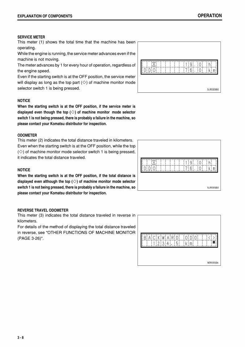
SERVICE METERThis meter (1) shows the total time that the machine has beenoperating.While the engine is running, the service meter advances even if themachine is not moving.The meter advances by 1 for every hour of operation, regardless ofthe engine speed.Even if the starting switch is at the OFF position, the service meterwill display as long as the top part ( ) of machine monitor modeselector switch 1 is being pressed.
NOTICEWhen the starting switch is at the OFF position, if the service meter isdisplayed even though the top ( ) of machine monitor mode selectorswitch 1 is not being pressed, there is probably a failure in the machine, soplease contact your Komatsu distributor for inspection.
ODOMETERThis meter (2) indicates the total distance traveled in kilometers.Even when the starting switch is at the OFF position, while the top( ) of machine monitor mode selector switch 1 is being pressed,it indicates the total distance traveled.
NOTICEWhen the starting switch is at the OFF position, if the total distance isdisplayed even although the top ( ) of machine monitor mode selectorswitch 1 is not being pressed, there is probably a failure in the machine, soplease contact your Komatsu distributor for inspection.
REVERSE TRAVEL ODOMETERThis meter (3) indicates the total distance traveled in reverse inkilometers.For details of the method of displaying the total distance traveledin reverse, see "OTHER FUNCTIONS OF MACHINE MONITOR(PAGE 3-26)".
3 - 8
.
OPERATION EXPLANATION OF COMPONENTS
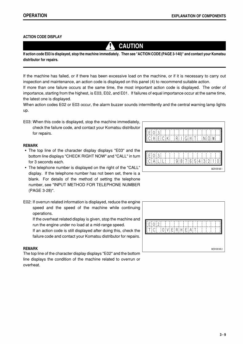
ACTION CODE DISPLAY
CAUTIONIf action code E03 is displayed, stop the machine immediately. Then see "ACTION CODE (PAGE 3-140)" and contact your Komatsudistributor for repairs.
If the machine has failed, or if there has been excessive load on the machine, or if it is necessary to carry outinspection and maintenance, an action code is displayed on this panel (4) to recommend suitable action.If more than one failure occurs at the same time, the most important action code is displayed. The order ofimportance, starting from the highest, is E03, E02, and E01. If failures of equal importance occur at the same time,the latest one is displayed.When action codes E02 or E03 occur, the alarm buzzer sounds intermittently and the central warning lamp lightsup.
E03: When this code is displayed, stop the machine immediately,check the failure code, and contact your Komatsu distributorfor repairs.
REMARKThe top line of the character display displays "E03" and thebottom line displays "CHECK RIGHT NOW" and "CALL" in turnfor 3 seconds each.The telephone number is displayed on the right of the "CALL"display. If the telephone number has not been set, there is ablank. For details of the method of setting the telephonenumber, see "INPUT METHOD FOR TELEPHONE NUMBER(PAGE 3-28)".
E02: If overrun related information is displayed, reduce the enginespeed and the speed of the machine while continuingoperations.If the overheat related display is given, stop the machine andrun the engine under no load at a mid-range speed.If an action code is still displayed after doing this, check thefailure code and contact your Komatsu distributor for repairs.
REMARKThe top line of the character display displays "E02" and the bottomline displays the condition of the machine related to overrun oroverheat.
3 - 9
.
OPERATIONEXPLANATION OF COMPONENTS OPERATIONEXPLANATION OF COMPONENTS
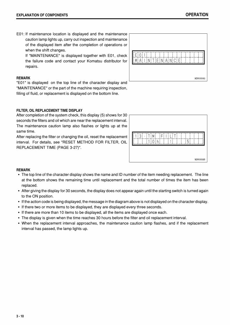
E01: If maintenance location is displayed and the maintenancecaution lamp lights up, carry out inspection and maintenanceof the displayed item after the completion of operations orwhen the shift changes.If "MAINTENANCE" is displayed together with E01, checkthe failure code and contact your Komatsu distributor forrepairs.
REMARK"E01" is displayed on the top line of the character display and"MAINTENANCE" or the part of the machine requiring inspection,filling of fluid, or replacement is displayed on the bottom line.
FILTER, OIL REPLACEMENT TIME DISPLAYAfter completion of the system check, this display (5) shows for 30seconds the filters and oil which are near the replacement interval.The maintenance caution lamp also flashes or lights up at thesame time.After replacing the filter or changing the oil, reset the replacementinterval. For details, see "RESET METHOD FOR FILTER, OILREPLACEMENT TIME (PAGE 3-27)".
REMARKThe top line of the character display shows the name and ID number of the item needing replacement. The lineat the bottom shows the remaining time until replacement and the total number of times the item has beenreplaced.After giving the display for 30 seconds, the display does not appear again until the starting switch is turned againto the ON position.If the action code is being displayed, the message in the diagram above is not displayed on the character display.If there two or more items to be displayed, they are displayed every three seconds.If there are more than 10 items to be displayed, all the items are displayed once each.The display is given when the time reaches 30 hours before the filter and oil replacement interval.When the replacement interval approaches, the maintenance caution lamp flashes, and if the replacementinterval has passed, the lamp lights up.
3 - 10
.
OPERATION EXPLANATION OF COMPONENTS
Items for display of filter, oil replacement time
ItemReplacement
intervalCharacter display ID number
Fuel prefilter 500 FUEL P FILT 41
Engine oil filter 500 ENG FILT 02
Engine oil 500 ENG OIL 01
Fuel main filter 1000 FUEL FILT 03
Corrosion resistor 1000 CORR RES 06
Transmission oil 1000 TM OIL 12
Transmission oil filter 1000 TM FILT 13
Brake oil filter 1000 BK OIL FILT 14
Brake cooling oil filter 1000 BK C FILT 16
Hydraulic filter 2000 HYD FILT 04
Differential case oil 2000 DIFF OIL 11
Final drive oil 2000 FNL OIL 08
Hydraulic oil 4000 HYD OIL 10
REMARKSee the section below for details of the procedure for replacing the filter and oil.
Fuel prefilter"REPLACE FUEL PREFILTER CARTRIDGE (PAGE 4-54)"Engine oil filter"CHANGE OIL IN ENGINE OIL PAN, REPLACE ENGINE OIL FILTER CARTRIDGE (PAGE 4-53)"Engine oil"CHANGE OIL IN ENGINE OIL PAN, REPLACE ENGINE OIL FILTER CARTRIDGE (PAGE 4-53)"Fuel main filter"REPLACE FUEL MAIN FILTER CARTRIDGE (PAGE 4-60)"Corrosion resistor"REPLACE CORROSION RESISTOR CARTRIDGE (PAGE 4-61)"Transmission oil"CHANGE OIL IN TRANSMISSION CASE (PAGE 4-63)"Transmission oil filter"REPLACE TRANSMISSION OIL FILTER ELEMENT - VALVE SIDE (PAGE 4-62)"Brake oil filter"CHANGE OIL IN BRAKE OIL TANK, REPLACE BRAKE OIL FILTER ELEMENT (PAGE 4-65)"Brake cooling oil filter"REPLACE TRANSMISSION OIL FILTER ELEMENT - BRAKE COOLING SIDE (PAGE 4-62)"Hydraulic filter"REPLACE HYDRAULIC FILTER ELEMENT (PAGE 4-73)"Differential case oil"CHANGE OIL IN DIFFERENTIAL CASE (PAGE 4-72)"Final drive oil"CHANGE OIL IN FINAL DRIVE CASE (PAGE 4-71)"Hydraulic oil"CHANGE OIL IN HYDRAULIC TANK (PAGE 4-77)"
3 - 11
.
OPERATIONEXPLANATION OF COMPONENTS
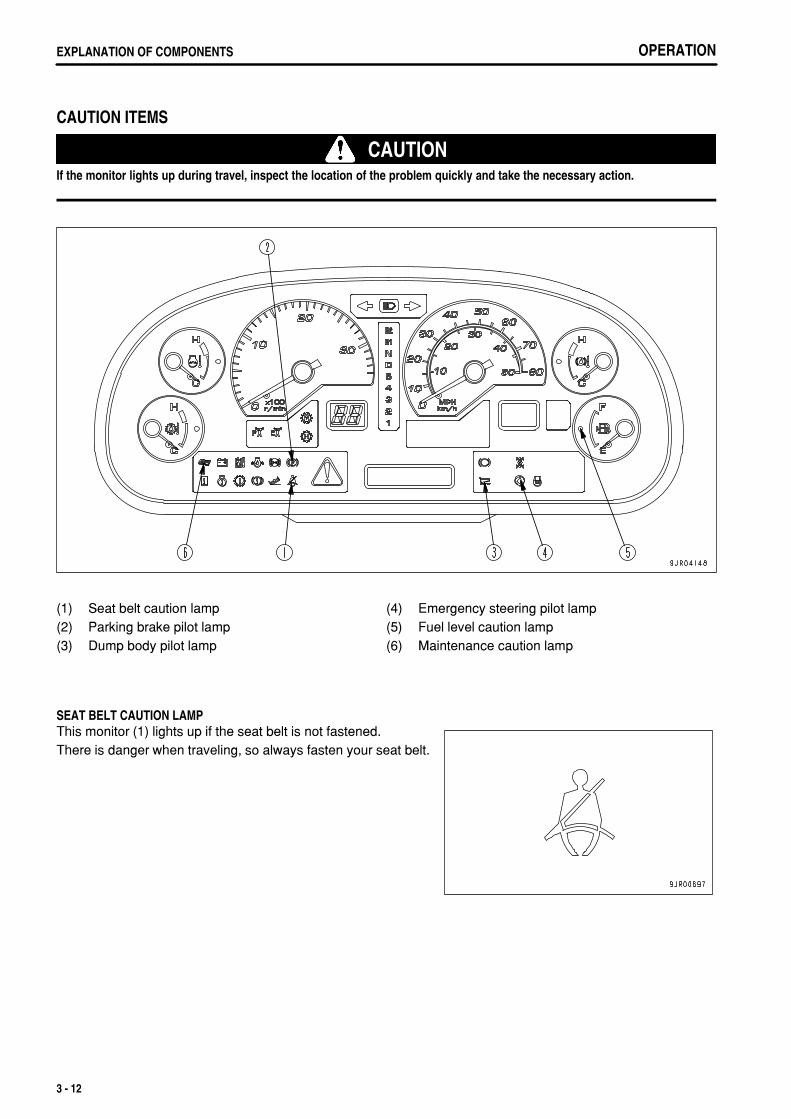
CAUTION ITEMS
CAUTIONIf the monitor lights up during travel, inspect the location of the problem quickly and take the necessary action.
(1)(2)(3)
Seat belt caution lampParking brake pilot lampDump body pilot lamp
(4)(5)(6)
Emergency steering pilot lampFuel level caution lampMaintenance caution lamp
SEAT BELT CAUTION LAMPThis monitor (1) lights up if the seat belt is not fastened.There is danger when traveling, so always fasten your seat belt.
3 - 12
.
OPERATION EXPLANATION OF COMPONENTS
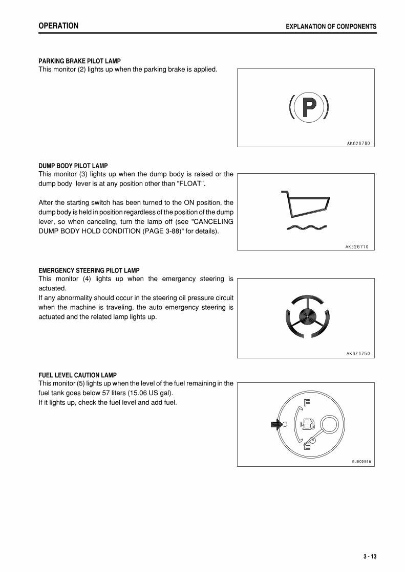
PARKING BRAKE PILOT LAMPThis monitor (2) lights up when the parking brake is applied.
DUMP BODY PILOT LAMPThis monitor (3) lights up when the dump body is raised or thedump body lever is at any position other than "FLOAT".
After the starting switch has been turned to the ON position, thedump body is held in position regardless of the position of the dumplever, so when canceling, turn the lamp off (see "CANCELINGDUMP BODY HOLD CONDITION (PAGE 3-88)" for details).
EMERGENCY STEERING PILOT LAMPThis monitor (4) lights up when the emergency steering isactuated.If any abnormality should occur in the steering oil pressure circuitwhen the machine is traveling, the auto emergency steering isactuated and the related lamp lights up.
FUEL LEVEL CAUTION LAMPThis monitor (5) lights up when the level of the fuel remaining in thefuel tank goes below 57 liters (15.06 US gal).If it lights up, check the fuel level and add fuel.
3 - 13
.
OPERATIONEXPLANATION OF COMPONENTS
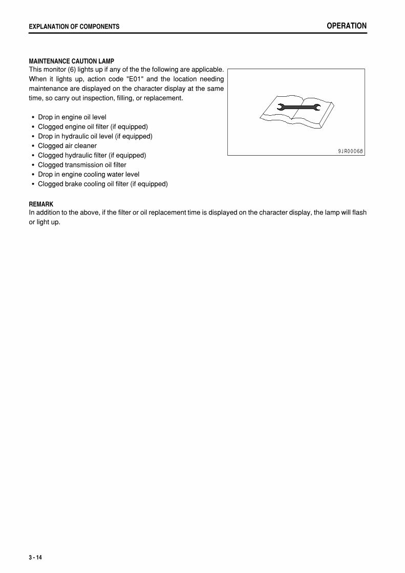
MAINTENANCE CAUTION LAMPThis monitor (6) lights up if any of the the following are applicable.When it lights up, action code "E01" and the location needingmaintenance are displayed on the character display at the sametime, so carry out inspection, filling, or replacement.
Drop in engine oil levelClogged engine oil filter (if equipped)Drop in hydraulic oil level (if equipped)Clogged air cleanerClogged hydraulic filter (if equipped)Clogged transmission oil filterDrop in engine cooling water levelClogged brake cooling oil filter (if equipped)
REMARKIn addition to the above, if the filter or oil replacement time is displayed on the character display, the lamp will flashor light up.
3 - 14
.
OPERATION EXPLANATION OF COMPONENTS
EMERGENCY STOP ITEM
CAUTIONIf the monitor lights up, stop operations immediately, then check the corresponding area and carry out the action.
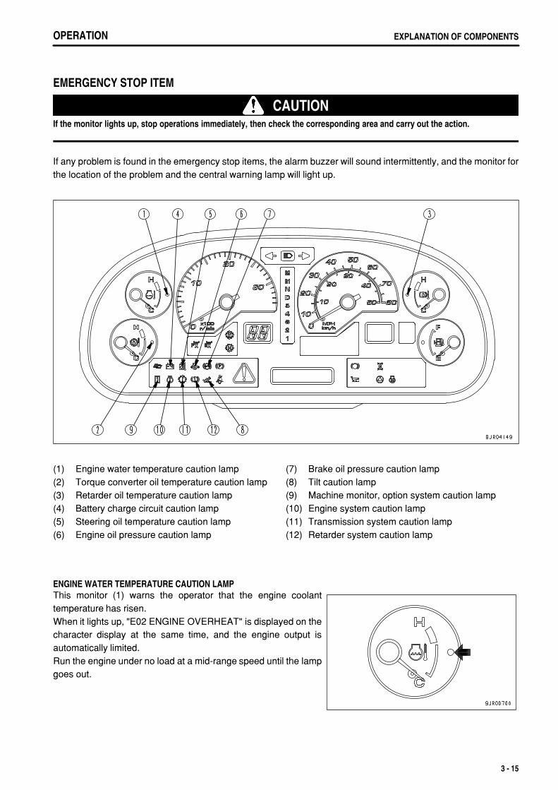
If any problem is found in the emergency stop items, the alarm buzzer will sound intermittently, and the monitor forthe location of the problem and the central warning lamp will light up.
(1)(2)(3)(4)(5)(6)
Engine water temperature caution lampTorque converter oil temperature caution lampRetarder oil temperature caution lampBattery charge circuit caution lampSteering oil temperature caution lampEngine oil pressure caution lamp
(7)(8)(9)(10)(11)(12)
Brake oil pressure caution lampTilt caution lampMachine monitor, option system caution lampEngine system caution lampTransmission system caution lampRetarder system caution lamp
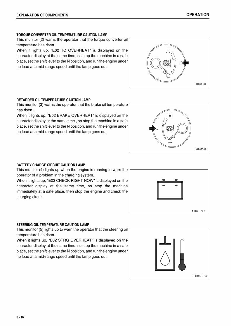
ENGINE WATER TEMPERATURE CAUTION LAMPThis monitor (1) warns the operator that the engine coolanttemperature has risen.When it lights up, "E02 ENGINE OVERHEAT" is displayed on thecharacter display at the same time, and the engine output isautomatically limited.Run the engine under no load at a mid-range speed until the lampgoes out.
3 - 15
.
OPERATIONEXPLANATION OF COMPONENTS
TORQUE CONVERTER OIL TEMPERATURE CAUTION LAMPThis monitor (2) warns the operator that the torque converter oiltemperature has risen.When it lights up, "E02 TC OVERHEAT" is displayed on thecharacter display at the same time, so stop the machine in a safeplace, set the shift lever to the N position, and run the engine underno load at a mid-range speed until the lamp goes out.
RETARDER OIL TEMPERATURE CAUTION LAMPThis monitor (3) warns the operator that the brake oil temperaturehas risen.When it lights up, "E02 BRAKE OVERHEAT" is displayed on thecharacter display at the same time , so stop the machine in a safeplace, set the shift lever to the N position, and run the engine underno load at a mid-range speed until the lamp goes out.
BATTERY CHARGE CIRCUIT CAUTION LAMPThis monitor (4) lights up when the engine is running to warn theoperator of a problem in the charging system.When it lights up, "E03 CHECK RIGHT NOW" is displayed on thecharacter display at the same time, so stop the machineimmediately at a safe place, then stop the engine and check thecharging circuit.
STEERING OIL TEMPERATURE CAUTION LAMPThis monitor (5) lights up to warn the operator that the steering oiltemperature has risen.When it lights up, "E02 STRG OVERHEAT" is displayed on thecharacter display at the same time, so stop the machine in a safeplace, set the shift lever to the N position, and run the engine underno load at a mid-range speed until the lamp goes out.
3 - 16
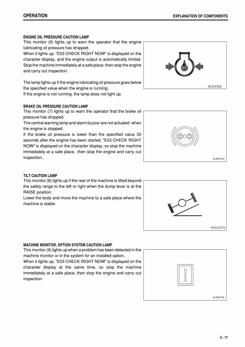
.
OPERATION EXPLANATION OF COMPONENTS
ENGINE OIL PRESSURE CAUTION LAMPThis monitor (6) lights up to warn the operator that the enginelubricating oil pressure has dropped.When it lights up, "E03 CHECK RIGHT NOW" is displayed on thecharacter display, and the engine output is automatically limited.Stop the machine immediately at a safe place, then stop the engineand carry out inspection.
The lamp lights up if the engine lubricating oil pressure goes belowthe specified value when the engine is running,If the engine is not running, the lamp does not light up.
BRAKE OIL PRESSURE CAUTION LAMPThis monitor (7) lights up to warn the operator that the brake oilpressure has dropped.The central warning lamp and alarm buzzer are not actuated whenthe engine is stopped.If the brake oil pressure is lower than the specified value 30seconds after the engine has been started, "E03 CHECK RIGHTNOW" is displayed on the character display, so stop the machineimmediately at a safe place, then stop the engine and carry outinspection.
TILT CAUTION LAMPThis monitor (8) lights up if the rear of the machine is tilted beyondthe safety range to the left or right when the dump lever is at theRAISE position.Lower the body and move the machine to a safe place where themachine is stable.
MACHINE MONITOR, OPTION SYSTEM CAUTION LAMPThis monitor (9) lights up when a problem has been detected in themachine monitor or in the system for an installed option.When it lights up, "E03 CHECK RIGHT NOW" is displayed on thecharacter display at the same time, so stop the machineimmediately at a safe place, then stop the engine and carry outinspection.
3 - 17
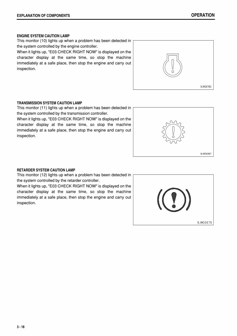
.
OPERATIONEXPLANATION OF COMPONENTS
ENGINE SYSTEM CAUTION LAMPThis monitor (10) lights up when a problem has been detected inthe system controlled by the engine controller.When it lights up, "E03 CHECK RIGHT NOW" is displayed on thecharacter display at the same time, so stop the machineimmediately at a safe place, then stop the engine and carry outinspection.
TRANSMISSION SYSTEM CAUTION LAMPThis monitor (11) lights up when a problem has been detected inthe system controlled by the transmission controller.When it lights up, "E03 CHECK RIGHT NOW" is displayed on thecharacter display at the same time, so stop the machineimmediately at a safe place, then stop the engine and carry outinspection.
RETARDER SYSTEM CAUTION LAMPThis monitor (12) lights up when a problem has been detected inthe system controlled by the retarder controller.When it lights up, "E03 CHECK RIGHT NOW" is displayed on thecharacter display at the same time, so stop the machineimmediately at a safe place, then stop the engine and carry outinspection.
3 - 18
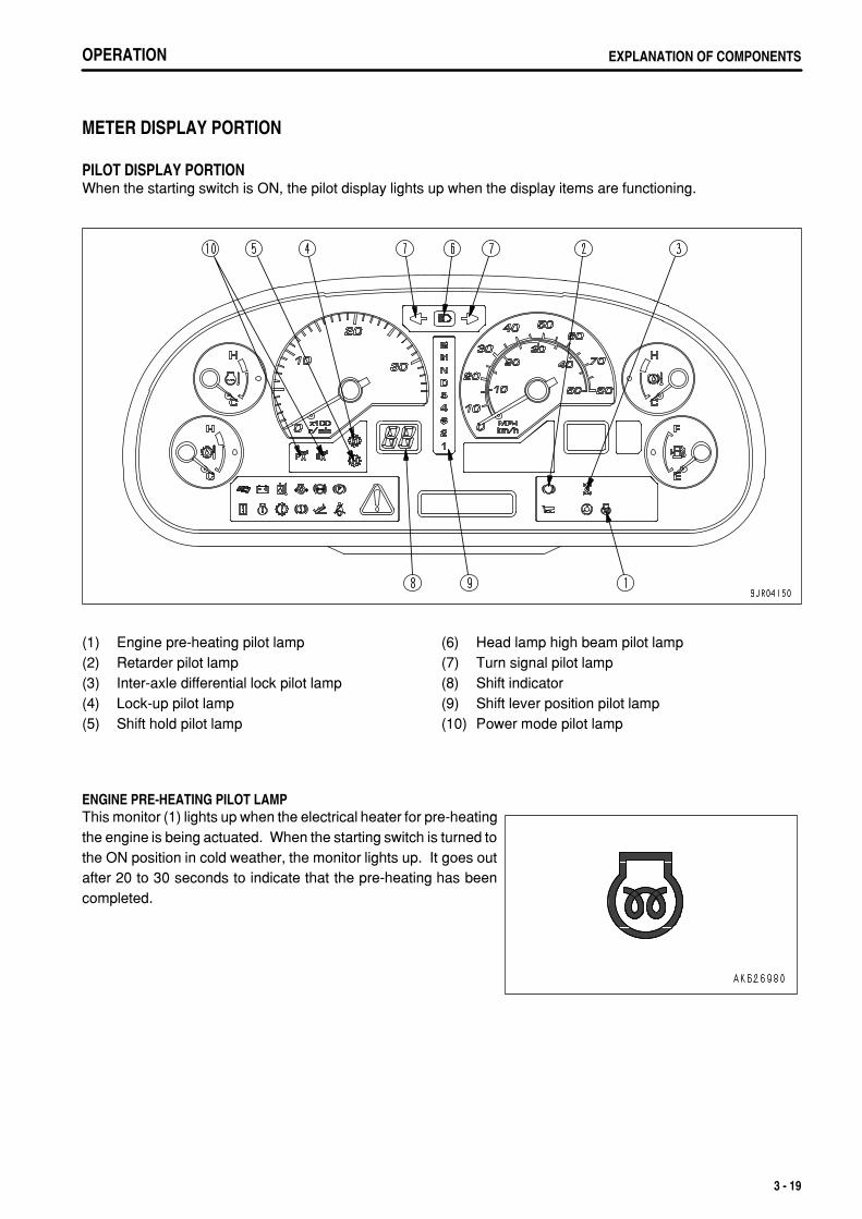
.
OPERATION EXPLANATION OF COMPONENTS
METER DISPLAY PORTION
PILOT DISPLAY PORTIONWhen the starting switch is ON, the pilot display lights up when the display items are functioning.
(1)(2)(3)(4)(5)
Engine pre-heating pilot lampRetarder pilot lampInter-axle differential lock pilot lampLock-up pilot lampShift hold pilot lamp
(6)(7)(8)(9)(10)
Head lamp high beam pilot lampTurn signal pilot lampShift indicatorShift lever position pilot lampPower mode pilot lamp
ENGINE PRE-HEATING PILOT LAMPThis monitor (1) lights up when the electrical heater for pre-heatingthe engine is being actuated. When the starting switch is turned tothe ON position in cold weather, the monitor lights up. It goes outafter 20 to 30 seconds to indicate that the pre-heating has beencompleted.
3 - 19
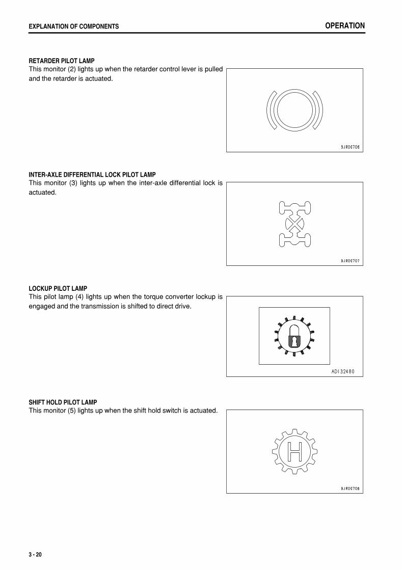
.
OPERATIONEXPLANATION OF COMPONENTS
RETARDER PILOT LAMPThis monitor (2) lights up when the retarder control lever is pulledand the retarder is actuated.
INTER-AXLE DIFFERENTIAL LOCK PILOT LAMPThis monitor (3) lights up when the inter-axle differential lock isactuated.
LOCKUP PILOT LAMPThis pilot lamp (4) lights up when the torque converter lockup isengaged and the transmission is shifted to direct drive.
SHIFT HOLD PILOT LAMPThis monitor (5) lights up when the shift hold switch is actuated.
3 - 20
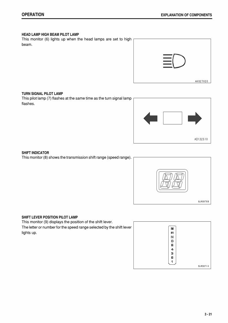
.
OPERATION EXPLANATION OF COMPONENTS
HEAD LAMP HIGH BEAM PILOT LAMPThis monitor (6) lights up when the head lamps are set to highbeam.
TURN SIGNAL PILOT LAMPThis pilot lamp (7) flashes at the same time as the turn signal lampflashes.
SHIFT INDICATORThis monitor (8) shows the transmission shift range (speed range).
SHIFT LEVER POSITION PILOT LAMPThis monitor (9) displays the position of the shift lever.The letter or number for the speed range selected by the shift leverlights up.
3 - 21

.
OPERATIONEXPLANATION OF COMPONENTS
POWER MODE PILOT LAMPThis monitor (10) displays the power mode.When the mode is selected with the power mode selector switch,either High Power (P) or Economy (E) lights up.
3 - 22
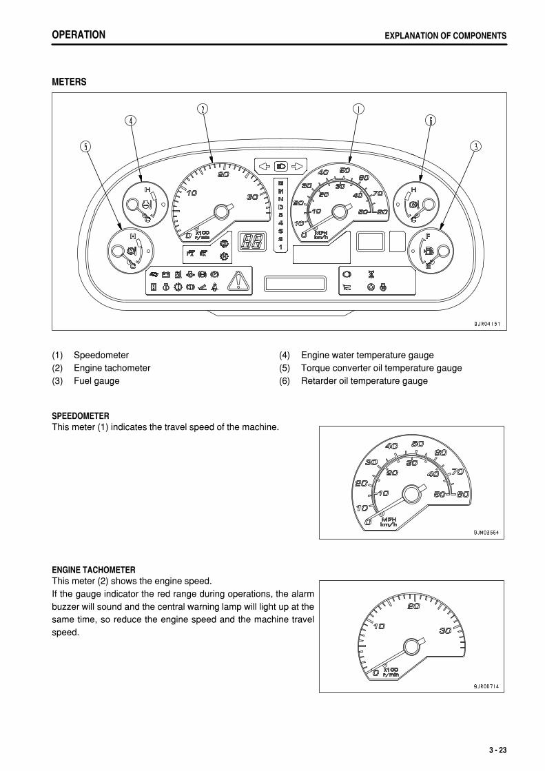
.
OPERATION EXPLANATION OF COMPONENTS
METERS
(1)(2)(3)
SpeedometerEngine tachometerFuel gauge
(4)(5)(6)
Engine water temperature gaugeTorque converter oil temperature gaugeRetarder oil temperature gauge
SPEEDOMETERThis meter (1) indicates the travel speed of the machine.
ENGINE TACHOMETERThis meter (2) shows the engine speed.If the gauge indicator the red range during operations, the alarmbuzzer will sound and the central warning lamp will light up at thesame time, so reduce the engine speed and the machine travelspeed.
3 - 23
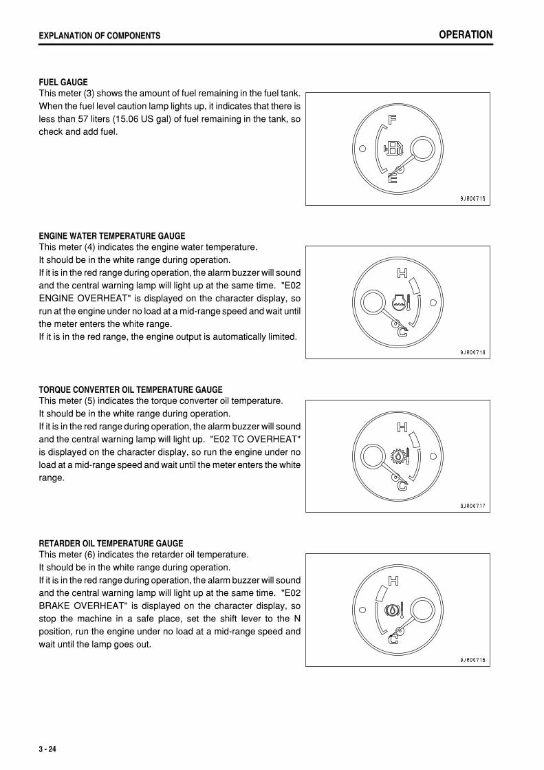
.
OPERATIONEXPLANATION OF COMPONENTS
FUEL GAUGEThis meter (3) shows the amount of fuel remaining in the fuel tank.When the fuel level caution lamp lights up, it indicates that there isless than 57 liters (15.06 US gal) of fuel remaining in the tank, socheck and add fuel.
ENGINE WATER TEMPERATURE GAUGEThis meter (4) indicates the engine water temperature.It should be in the white range during operation.If it is in the red range during operation, the alarm buzzer will soundand the central warning lamp will light up at the same time. "E02ENGINE OVERHEAT" is displayed on the character display, sorun at the engine under no load at a mid-range speed and wait untilthe meter enters the white range.If it is in the red range, the engine output is automatically limited.
TORQUE CONVERTER OIL TEMPERATURE GAUGEThis meter (5) indicates the torque converter oil temperature.It should be in the white range during operation.If it is in the red range during operation, the alarm buzzer will soundand the central warning lamp will light up. "E02 TC OVERHEAT"is displayed on the character display, so run the engine under noload at a mid-range speed and wait until the meter enters the whiterange.
RETARDER OIL TEMPERATURE GAUGEThis meter (6) indicates the retarder oil temperature.It should be in the white range during operation.If it is in the red range during operation, the alarm buzzer will soundand the central warning lamp will light up at the same time. "E02BRAKE OVERHEAT" is displayed on the character display, sostop the machine in a safe place, set the shift lever to the Nposition, run the engine under no load at a mid-range speed andwait until the lamp goes out.
3 - 24
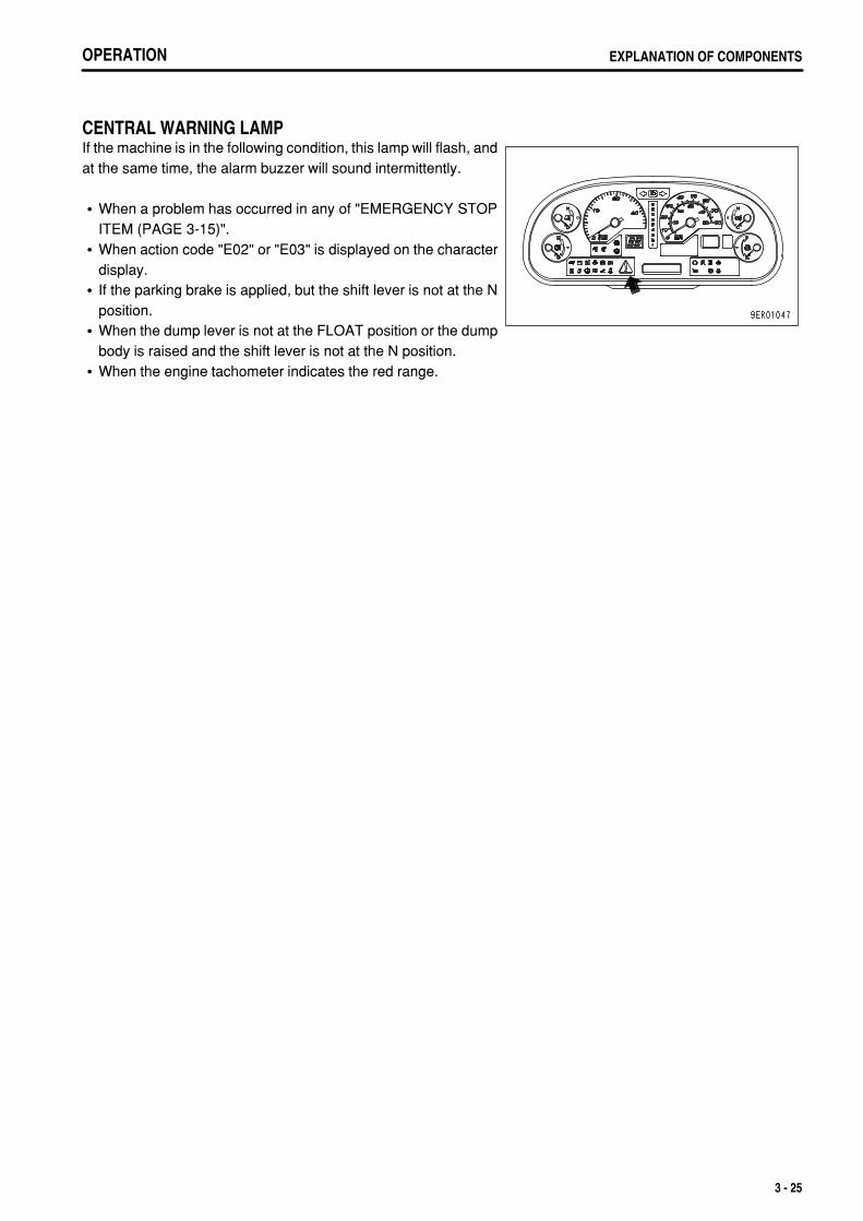
.
OPERATION EXPLANATION OF COMPONENTS
CENTRAL WARNING LAMPIf the machine is in the following condition, this lamp will flash, andat the same time, the alarm buzzer will sound intermittently.
When a problem has occurred in any of "EMERGENCY STOPITEM (PAGE 3-15)".When action code "E02" or "E03" is displayed on the characterdisplay.If the parking brake is applied, but the shift lever is not at the Nposition.When the dump lever is not at the FLOAT position or the dumpbody is raised and the shift lever is not at the N position.When the engine tachometer indicates the red range.
3 - 25
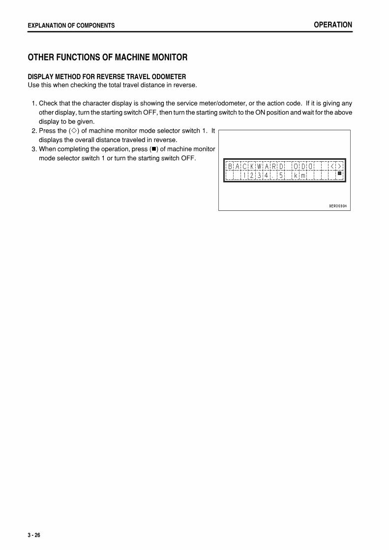
.
OPERATIONEXPLANATION OF COMPONENTS
OTHER FUNCTIONS OF MACHINE MONITOR
DISPLAY METHOD FOR REVERSE TRAVEL ODOMETERUse this when checking the total travel distance in reverse.
1. Check that the character display is showing the service meter/odometer, or the action code. If it is giving anyother display, turn the starting switch OFF, then turn the starting switch to the ON position and wait for the abovedisplay to be given.
2. Press the ( ) of machine monitor mode selector switch 1. Itdisplays the overall distance traveled in reverse.
3. When completing the operation, press ( ) of machine monitormode selector switch 1 or turn the starting switch OFF.
3 - 26
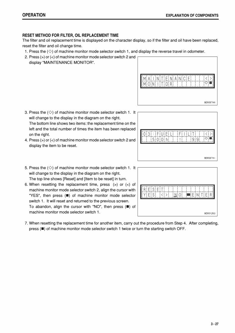
.
OPERATION EXPLANATION OF COMPONENTS
RESET METHOD FOR FILTER, OIL REPLACEMENT TIMEThe filter and oil replacement time is displayed on the character display, so if the filter and oil have been replaced,reset the filter and oil change time. 1. Press the ( ) of machine monitor mode selector switch 1, and display the reverse travel in odometer. 2. Press (>) or (<) of machine monitor mode selector switch 2 and
display "MAINTENANCE MONITOR".
3. Press the ( ) of machine monitor mode selector switch 1. Itwill change to the display in the diagram on the right.The bottom line shows two items: the replacement time on theleft and the total number of times the item has been replacedon the right.
4. Press (>) or (<) of machine monitor mode selector switch 2 anddisplay the item to be reset.
5. Press the ( ) of machine monitor mode selector switch 1. Itwill change to the display in the diagram on the right.The top line shows [Reset] and [Item to be reset] in turn.
6. When resetting the replacement time, press (>) or (<) ofmachine monitor mode selector switch 2, align the cursor with"YES", then press ( ) of machine monitor mode selectorswitch 1. It will reset and returned to the previous screen.To abandon, align the cursor with "NO", then press ( ) ofmachine monitor mode selector switch 1.
7. When resetting the replacement time for another item, carry out the procedure from Step 4. After completing,press ( ) of machine monitor mode selector switch 1 twice or turn the starting switch OFF.
3 - 27
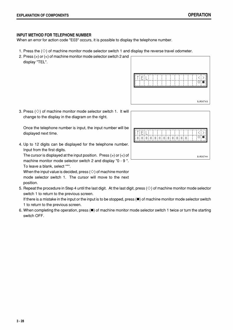
.
OPERATIONEXPLANATION OF COMPONENTS
INPUT METHOD FOR TELEPHONE NUMBERWhen an error for action code "E03" occurs, it is possible to display the telephone number.
1. Press the ( ) of machine monitor mode selector switch 1 and display the reverse travel odometer. 2. Press (>) or (<) of machine monitor mode selector switch 2 and
display "TEL".
3. Press ( ) of machine monitor mode selector switch 1. It willchange to the display in the diagram on the right.
Once the telephone number is input, the input number will bedisplayed next time.
4. Up to 12 digits can be displayed for the telephone number.Input from the first digits.The cursor is displayed at the input position. Press (>) or (<) ofmachine monitor mode selector switch 2 and display "0 - 9 ".To leave a blank, select "*".When the input value is decided, press ( ) of machine monitormode selector switch 1. The cursor will move to the nextposition.
5. Repeat the procedure in Step 4 until the last digit. At the last digit, press ( ) of machine monitor mode selectorswitch 1 to return to the previous screen.If there is a mistake in the input or the input is to be stopped, press ( ) of machine monitor mode selector switch1 to return to the previous screen.
6. When completing the operation, press ( ) of machine monitor mode selector switch 1 twice or turn the startingswitch OFF.
3 - 28
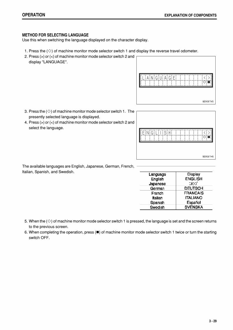
.
OPERATION EXPLANATION OF COMPONENTS
METHOD FOR SELECTING LANGUAGEUse this when switching the language displayed on the character display.
1. Press the ( ) of machine monitor mode selector switch 1 and display the reverse travel odometer. 2. Press (>) or (<) of machine monitor mode selector switch 2 and
display "LANGUAGE".
3. Press the ( ) of machine monitor mode selector switch 1. Thepresently selected language is displayed.
4. Press (>) or (<) of machine monitor mode selector switch 2 andselect the language.
The available languages are English, Japanese, German, French,Italian, Spanish, and Swedish.
5. When the ( ) of machine monitor mode selector switch 1 is pressed, the language is set and the screen returnsto the previous screen.
6. When completing the operation, press ( ) of machine monitor mode selector switch 1 twice or turn the startingswitch OFF.
3 - 29
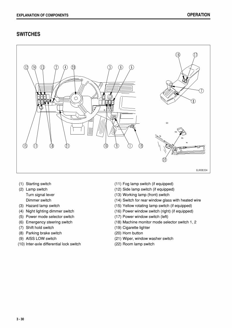
.
OPERATIONEXPLANATION OF COMPONENTS
SWITCHES
(1)(2)
(3)(4)(5)(6)(7)(8)(9)
(10)
Starting switchLamp switchTurn signal leverDimmer switchHazard lamp switchNight lighting dimmer switchPower mode selector switchEmergency steering switchShift hold switchParking brake switchAISS LOW switchInter-axle differential lock switch
(11)(12)(13)(14)(15)(16)(17)(18)(19)(20)(21)(22)
Fog lamp switch (if equipped)Side lamp switch (if equipped)Working lamp (front) switchSwitch for rear window glass with heated wireYellow rotating lamp switch (if equipped)Power window switch (right) (if equipped)Power window switch (left)Machine monitor mode selector switch 1, 2Cigarette lighterHorn buttonWiper, window washer switchRoom lamp switch
3 - 30
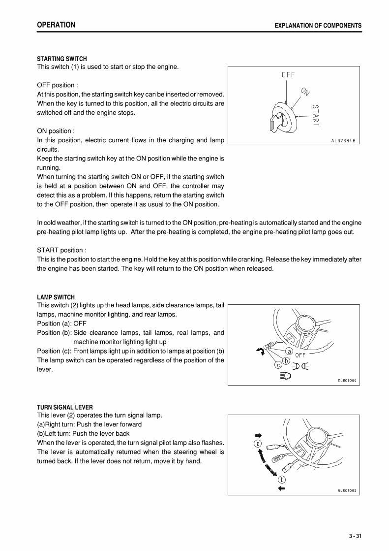
.
OPERATION EXPLANATION OF COMPONENTS
STARTING SWITCHThis switch (1) is used to start or stop the engine.
OFF position :At this position, the starting switch key can be inserted or removed.When the key is turned to this position, all the electric circuits areswitched off and the engine stops.
ON position :In this position, electric current flows in the charging and lampcircuits.Keep the starting switch key at the ON position while the engine isrunning.When turning the starting switch ON or OFF, if the starting switchis held at a position between ON and OFF, the controller maydetect this as a problem. If this happens, return the starting switchto the OFF position, then operate it as usual to the ON position.
In cold weather, if the starting switch is turned to the ON position, pre-heating is automatically started and the enginepre-heating pilot lamp lights up. After the pre-heating is completed, the engine pre-heating pilot lamp goes out.
START position :This is the position to start the engine. Hold the key at this position while cranking. Release the key immediately afterthe engine has been started. The key will return to the ON position when released.
LAMP SWITCHThis switch (2) lights up the head lamps, side clearance lamps, taillamps, machine monitor lighting, and rear lamps.Position (a): OFFPosition (b): Side clearance lamps, tail lamps, real lamps, and
machine monitor lighting light upPosition (c): Front lamps light up in addition to lamps at position (b)The lamp switch can be operated regardless of the position of thelever.
TURN SIGNAL LEVERThis lever (2) operates the turn signal lamp.(a)Right turn: Push the lever forward(b)Left turn: Push the lever backWhen the lever is operated, the turn signal pilot lamp also flashes.The lever is automatically returned when the steering wheel isturned back. If the lever does not return, move it by hand.
3 - 31
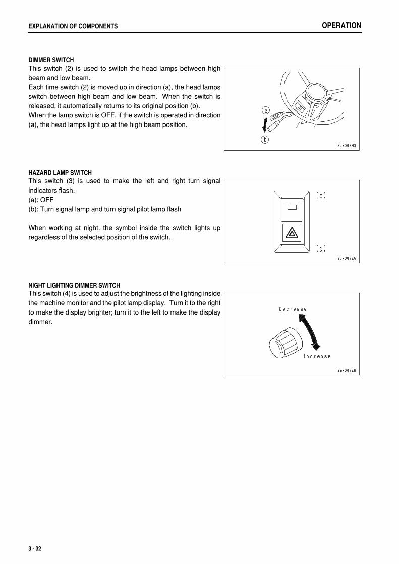
.
OPERATIONEXPLANATION OF COMPONENTS
DIMMER SWITCHThis switch (2) is used to switch the head lamps between highbeam and low beam.Each time switch (2) is moved up in direction (a), the head lampsswitch between high beam and low beam. When the switch isreleased, it automatically returns to its original position (b).When the lamp switch is OFF, if the switch is operated in direction(a), the head lamps light up at the high beam position.
HAZARD LAMP SWITCHThis switch (3) is used to make the left and right turn signalindicators flash.(a): OFF(b): Turn signal lamp and turn signal pilot lamp flash
When working at night, the symbol inside the switch lights upregardless of the selected position of the switch.
NIGHT LIGHTING DIMMER SWITCHThis switch (4) is used to adjust the brightness of the lighting insidethe machine monitor and the pilot lamp display. Turn it to the rightto make the display brighter; turn it to the left to make the displaydimmer.
3 - 32
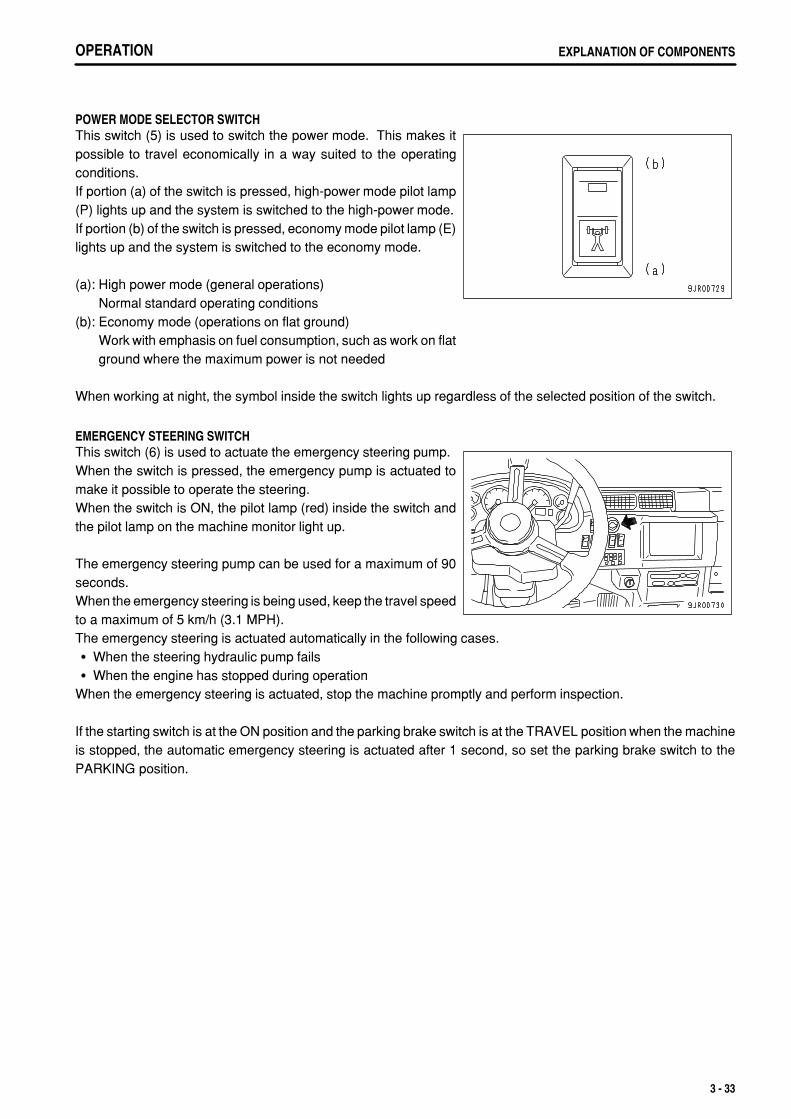
.
OPERATION EXPLANATION OF COMPONENTS
POWER MODE SELECTOR SWITCH This switch (5) is used to switch the power mode. This makes itpossible to travel economically in a way suited to the operatingconditions.If portion (a) of the switch is pressed, high-power mode pilot lamp(P) lights up and the system is switched to the high-power mode.If portion (b) of the switch is pressed, economy mode pilot lamp (E)lights up and the system is switched to the economy mode.
(a): High power mode (general operations)Normal standard operating conditions
(b): Economy mode (operations on flat ground)Work with emphasis on fuel consumption, such as work on flatground where the maximum power is not needed
When working at night, the symbol inside the switch lights up regardless of the selected position of the switch.
EMERGENCY STEERING SWITCHThis switch (6) is used to actuate the emergency steering pump.When the switch is pressed, the emergency pump is actuated tomake it possible to operate the steering.When the switch is ON, the pilot lamp (red) inside the switch andthe pilot lamp on the machine monitor light up.
The emergency steering pump can be used for a maximum of 90seconds.When the emergency steering is being used, keep the travel speedto a maximum of 5 km/h (3.1 MPH).The emergency steering is actuated automatically in the following cases.
When the steering hydraulic pump failsWhen the engine has stopped during operation
When the emergency steering is actuated, stop the machine promptly and perform inspection.
If the starting switch is at the ON position and the parking brake switch is at the TRAVEL position when the machineis stopped, the automatic emergency steering is actuated after 1 second, so set the parking brake switch to thePARKING position.
3 - 33
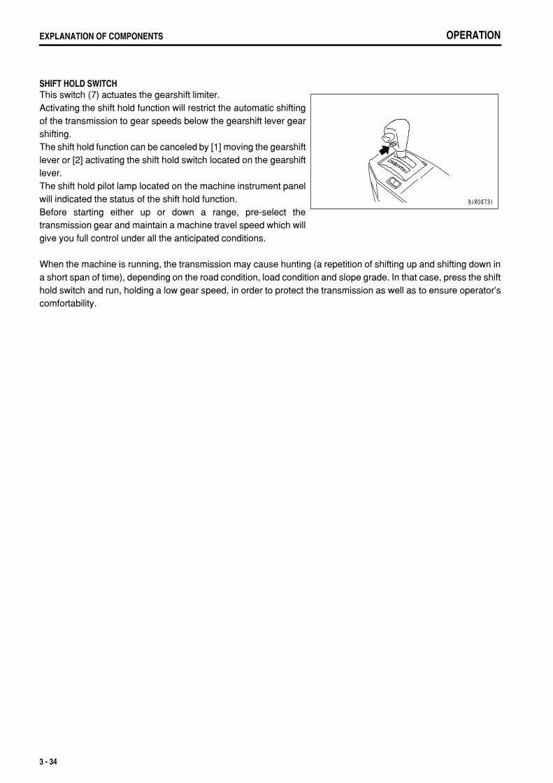
.
OPERATIONEXPLANATION OF COMPONENTS
SHIFT HOLD SWITCHThis switch (7) actuates the gearshift limiter.Activating the shift hold function will restrict the automatic shiftingof the transmission to gear speeds below the gearshift lever gearshifting.The shift hold function can be canceled by [1] moving the gearshiftlever or [2] activating the shift hold switch located on the gearshiftlever.The shift hold pilot lamp located on the machine instrument panelwill indicated the status of the shift hold function.Before starting either up or down a range, pre-select thetransmission gear and maintain a machine travel speed which willgive you full control under all the anticipated conditions.
When the machine is running, the transmission may cause hunting (a repetition of shifting up and shifting down ina short span of time), depending on the road condition, load condition and slope grade. In that case, press the shifthold switch and run, holding a low gear speed, in order to protect the transmission as well as to ensure operator'scomfortability.
3 - 34
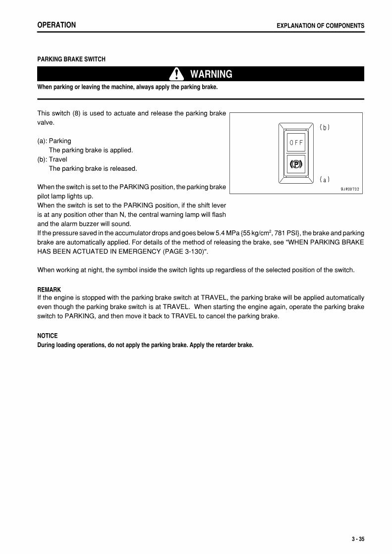
.
OPERATION EXPLANATION OF COMPONENTS
PARKING BRAKE SWITCH
WARNINGWhen parking or leaving the machine, always apply the parking brake.
This switch (8) is used to actuate and release the parking brakevalve.
(a): ParkingThe parking brake is applied.
(b): TravelThe parking brake is released.
When the switch is set to the PARKING position, the parking brakepilot lamp lights up.When the switch is set to the PARKING position, if the shift leveris at any position other than N, the central warning lamp will flashand the alarm buzzer will sound.If the pressure saved in the accumulator drops and goes below 5.4 MPa {55 kg/cm2, 781 PSI}, the brake and parkingbrake are automatically applied. For details of the method of releasing the brake, see "WHEN PARKING BRAKEHAS BEEN ACTUATED IN EMERGENCY (PAGE 3-130)".
When working at night, the symbol inside the switch lights up regardless of the selected position of the switch.
REMARKIf the engine is stopped with the parking brake switch at TRAVEL, the parking brake will be applied automaticallyeven though the parking brake switch is at TRAVEL. When starting the engine again, operate the parking brakeswitch to PARKING, and then move it back to TRAVEL to cancel the parking brake.
NOTICEDuring loading operations, do not apply the parking brake. Apply the retarder brake.
3 - 35
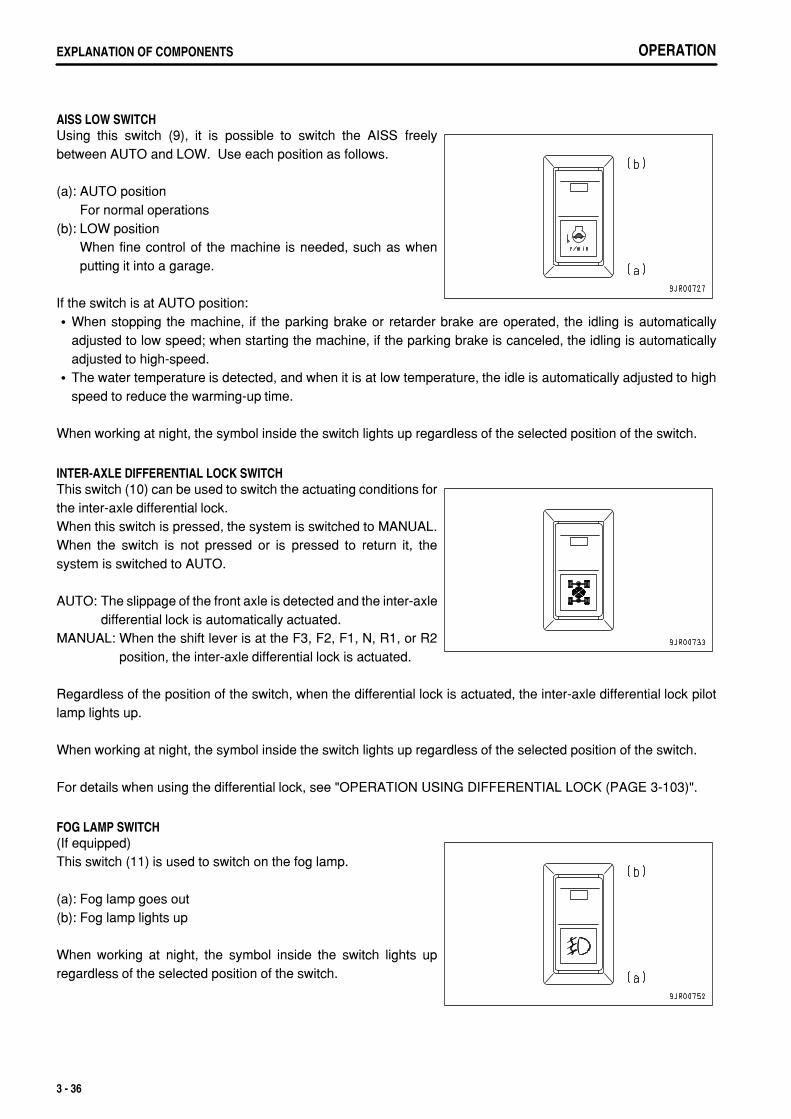
.
OPERATIONEXPLANATION OF COMPONENTS
AISS LOW SWITCHUsing this switch (9), it is possible to switch the AISS freelybetween AUTO and LOW. Use each position as follows.
(a): AUTO positionFor normal operations
(b): LOW positionWhen fine control of the machine is needed, such as whenputting it into a garage.
If the switch is at AUTO position:When stopping the machine, if the parking brake or retarder brake are operated, the idling is automaticallyadjusted to low speed; when starting the machine, if the parking brake is canceled, the idling is automaticallyadjusted to high-speed.The water temperature is detected, and when it is at low temperature, the idle is automatically adjusted to highspeed to reduce the warming-up time.
When working at night, the symbol inside the switch lights up regardless of the selected position of the switch.
INTER-AXLE DIFFERENTIAL LOCK SWITCHThis switch (10) can be used to switch the actuating conditions forthe inter-axle differential lock.When this switch is pressed, the system is switched to MANUAL.When the switch is not pressed or is pressed to return it, thesystem is switched to AUTO.
AUTO: The slippage of the front axle is detected and the inter-axledifferential lock is automatically actuated.
MANUAL: When the shift lever is at the F3, F2, F1, N, R1, or R2position, the inter-axle differential lock is actuated.
Regardless of the position of the switch, when the differential lock is actuated, the inter-axle differential lock pilotlamp lights up.
When working at night, the symbol inside the switch lights up regardless of the selected position of the switch.
For details when using the differential lock, see "OPERATION USING DIFFERENTIAL LOCK (PAGE 3-103)".
FOG LAMP SWITCH(If equipped)This switch (11) is used to switch on the fog lamp.
(a): Fog lamp goes out(b): Fog lamp lights up
When working at night, the symbol inside the switch lights upregardless of the selected position of the switch.
3 - 36
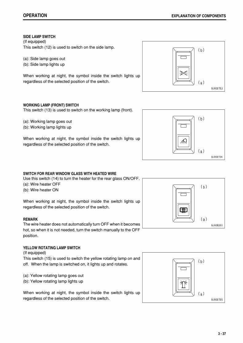
.
OPERATION EXPLANATION OF COMPONENTS
SIDE LAMP SWITCH(If equipped)This switch (12) is used to switch on the side lamp.
(a): Side lamp goes out(b): Side lamp lights up
When working at night, the symbol inside the switch lights upregardless of the selected position of the switch.
WORKING LAMP (FRONT) SWITCHThis switch (13) is used to switch on the working lamp (front).
(a): Working lamp goes out(b): Working lamp lights up
When working at night, the symbol inside the switch lights upregardless of the selected position of the switch.
SWITCH FOR REAR WINDOW GLASS WITH HEATED WIREUse this switch (14) to turn the heater for the rear glass ON/OFF.(a): Wire heater OFF(b): Wire heater ON
When working at night, the symbol inside the switch lights upregardless of the selected position of the switch.
REMARKThe wire heater does not automatically turn OFF when it becomeshot, so when it is not needed, turn the switch manually to the OFFposition.
YELLOW ROTATING LAMP SWITCH(If equipped)This switch (15) is used to switch the yellow rotating lamp on andoff. When the lamp is switched on, it lights up and rotates.
(a): Yellow rotating lamp goes out(b): Yellow rotating lamp lights up
When working at night, the symbol inside the switch lights upregardless of the selected position of the switch.
3 - 37
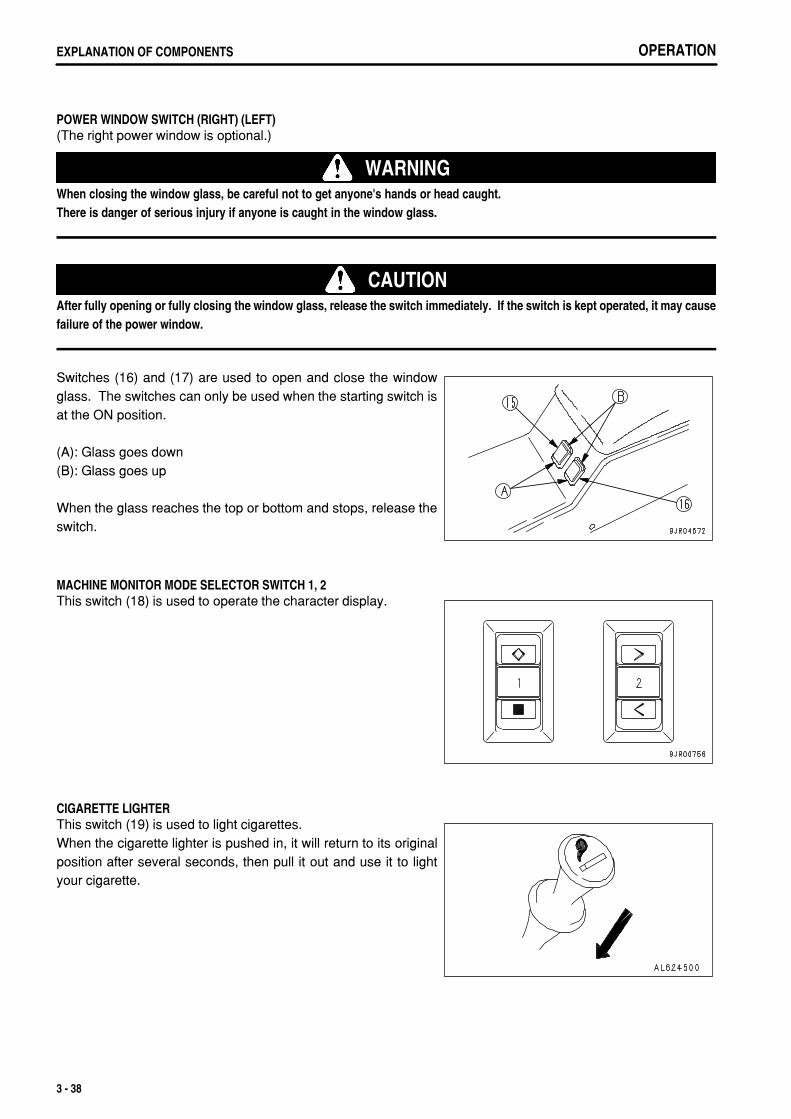
.
OPERATIONEXPLANATION OF COMPONENTS
POWER WINDOW SWITCH (RIGHT) (LEFT)(The right power window is optional.)
WARNINGWhen closing the window glass, be careful not to get anyone's hands or head caught.There is danger of serious injury if anyone is caught in the window glass.
CAUTIONAfter fully opening or fully closing the window glass, release the switch immediately. If the switch is kept operated, it may causefailure of the power window.
Switches (16) and (17) are used to open and close the windowglass. The switches can only be used when the starting switch isat the ON position.
(A): Glass goes down(B): Glass goes up
When the glass reaches the top or bottom and stops, release theswitch.
MACHINE MONITOR MODE SELECTOR SWITCH 1, 2This switch (18) is used to operate the character display.
CIGARETTE LIGHTERThis switch (19) is used to light cigarettes.When the cigarette lighter is pushed in, it will return to its originalposition after several seconds, then pull it out and use it to lightyour cigarette.
3 - 38
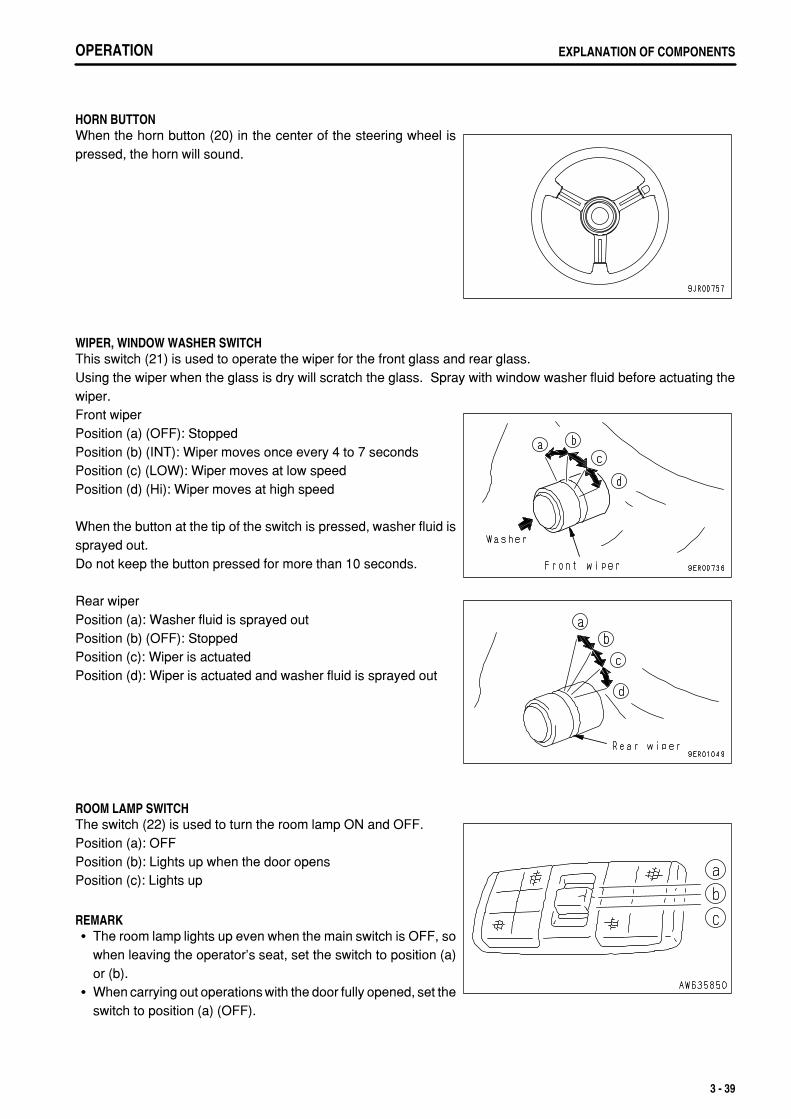
.
OPERATION EXPLANATION OF COMPONENTS
HORN BUTTONWhen the horn button (20) in the center of the steering wheel ispressed, the horn will sound.
WIPER, WINDOW WASHER SWITCHThis switch (21) is used to operate the wiper for the front glass and rear glass.Using the wiper when the glass is dry will scratch the glass. Spray with window washer fluid before actuating thewiper.Front wiperPosition (a) (OFF): StoppedPosition (b) (INT): Wiper moves once every 4 to 7 secondsPosition (c) (LOW): Wiper moves at low speedPosition (d) (Hi): Wiper moves at high speed
When the button at the tip of the switch is pressed, washer fluid issprayed out.Do not keep the button pressed for more than 10 seconds.
Rear wiperPosition (a): Washer fluid is sprayed outPosition (b) (OFF): StoppedPosition (c): Wiper is actuatedPosition (d): Wiper is actuated and washer fluid is sprayed out
ROOM LAMP SWITCHThe switch (22) is used to turn the room lamp ON and OFF.Position (a): OFFPosition (b): Lights up when the door opensPosition (c): Lights up
REMARKThe room lamp lights up even when the main switch is OFF, sowhen leaving the operator's seat, set the switch to position (a)or (b).When carrying out operations with the door fully opened, set theswitch to position (a) (OFF).
3 - 39
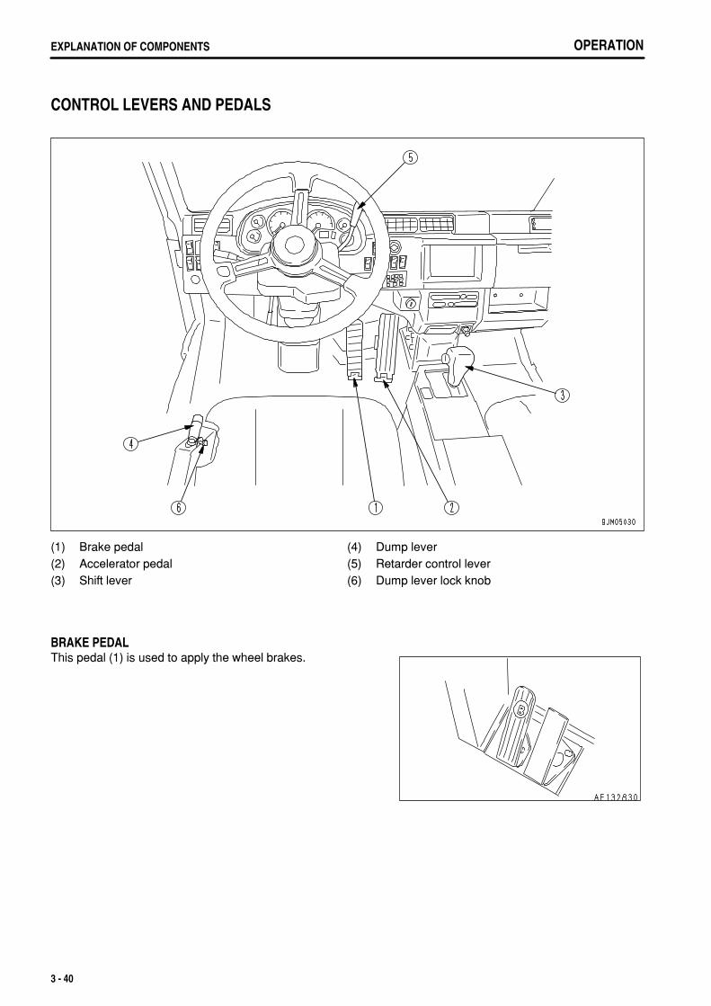
.
OPERATIONEXPLANATION OF COMPONENTS
CONTROL LEVERS AND PEDALS
(1)(2)(3)
Brake pedalAccelerator pedalShift lever
(4)(5)(6)
Dump leverRetarder control leverDump lever lock knob
BRAKE PEDALThis pedal (1) is used to apply the wheel brakes.
3 - 40
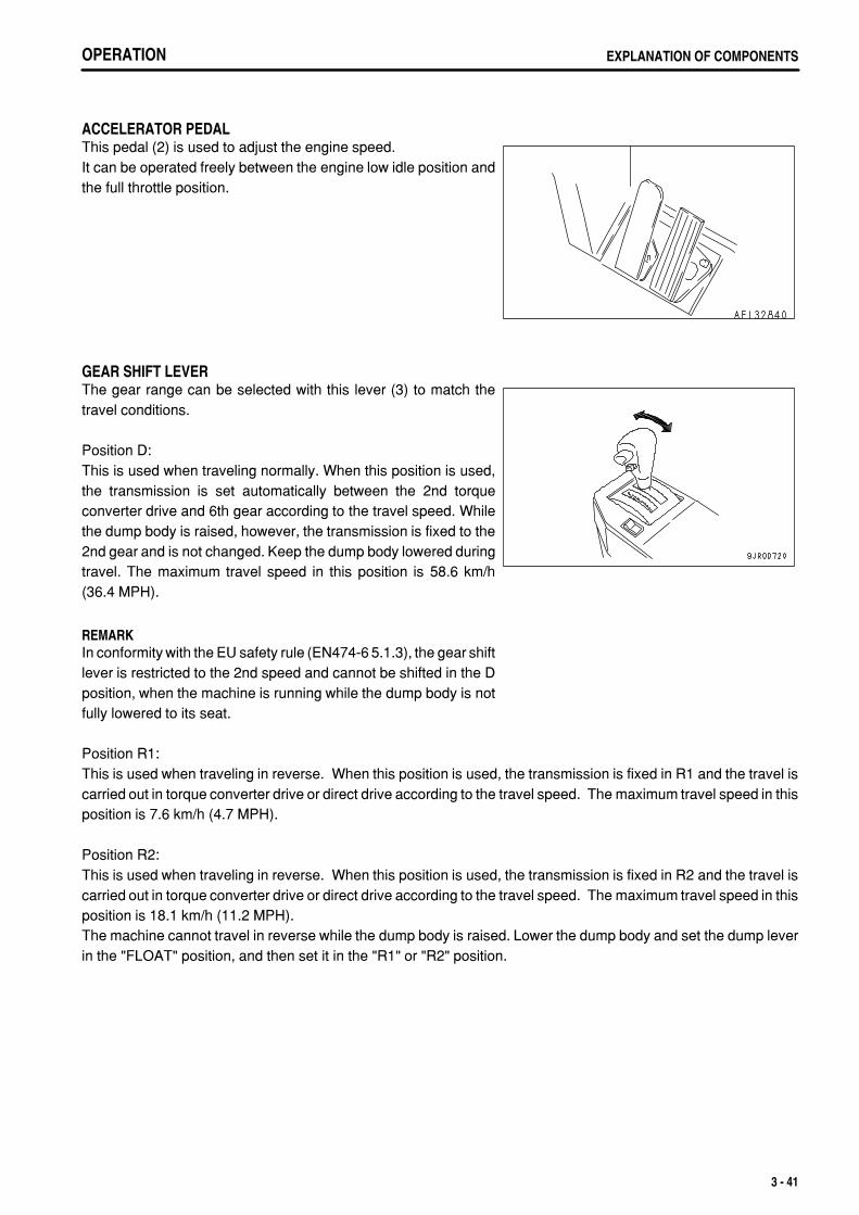
.
OPERATION EXPLANATION OF COMPONENTS
ACCELERATOR PEDALThis pedal (2) is used to adjust the engine speed.It can be operated freely between the engine low idle position andthe full throttle position.
GEAR SHIFT LEVERThe gear range can be selected with this lever (3) to match thetravel conditions.
Position D:This is used when traveling normally. When this position is used,the transmission is set automatically between the 2nd torqueconverter drive and 6th gear according to the travel speed. Whilethe dump body is raised, however, the transmission is fixed to the2nd gear and is not changed. Keep the dump body lowered duringtravel. The maximum travel speed in this position is 58.6 km/h(36.4 MPH).
REMARKIn conformity with the EU safety rule (EN474-6 5.1.3), the gear shiftlever is restricted to the 2nd speed and cannot be shifted in the Dposition, when the machine is running while the dump body is notfully lowered to its seat.
Position R1:This is used when traveling in reverse. When this position is used, the transmission is fixed in R1 and the travel iscarried out in torque converter drive or direct drive according to the travel speed. The maximum travel speed in thisposition is 7.6 km/h (4.7 MPH).
Position R2:This is used when traveling in reverse. When this position is used, the transmission is fixed in R2 and the travel iscarried out in torque converter drive or direct drive according to the travel speed. The maximum travel speed in thisposition is 18.1 km/h (11.2 MPH).The machine cannot travel in reverse while the dump body is raised. Lower the dump body and set the dump leverin the "FLOAT" position, and then set it in the "R1" or "R2" position.
3 - 41
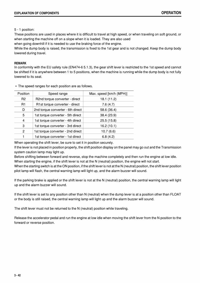
.
OPERATIONEXPLANATION OF COMPONENTS
5 - 1 position:These positions are used in places where it is difficult to travel at high speed, or when traveling on soft ground, orwhen starting the machine off on a slope when it is loaded. They are also usedwhen going downhill if it is needed to use the braking force of the engine.While the dump body is raised, the transmission is fixed to the 1st gear and is not changed. Keep the dump bodylowered during travel.
REMARKIn conformity with the EU safety rule (EN474-6 5.1.3), the gear shift lever is restricted to the 1st speed and cannotbe shifted if it is anywhere between 1 to 5 positions, when the machine is running while the dump body is not fullylowered to its seat.
The speed ranges for each position are as follows.
Position Speed range Max. speed [km/h (MPH)]
R2 R2nd torque converter - direct 18.1 (11.2)
R1 R1st torque converter - direct 7.6 (4.7)
D 2nd torque converter - 6th direct 58.6 (36.4)
5 1st torque converter - 5th direct 38.4 (23.9)
4 1st torque converter - 4th direct 25.5 (15.8)
3 1st torque converter - 3rd direct 16.2 (10.1)
2 1st torque converter - 2nd direct 10.7 (6.6)
1 1st torque converter - 1st direct 6.8 (4.2)
When operating the shift lever, be sure to set it in position securely.If the lever is not placed in position properly, the shift position display on the panel may go out and the Transmissionsystem caution lamp may light up.Before shifting between forward and reverse, stop the machine completely and then run the engine at low idle.When starting the engine, if the shift lever is not at the N (neutral) position, the engine will not start.When the starting switch is at the ON position, if the shift lever is not at the N (neutral) position, the shift lever positionpilot lamp will flash, the central warning lamp will light up, and the alarm buzzer will sound.
If the parking brake is applied or the shift lever is not at the N (neutral) position, the central warning lamp will lightup and the alarm buzzer will sound.
If the shift lever is set to any position other than N (neutral) when the dump lever is at a position other than FLOATor the body is still raised, the central warning lamp will light up and the alarm buzzer will sound.
The shift lever must not be returned to the N (neutral) position while traveling.
Release the accelerator pedal and run the engine at low idle when moving the shift lever from the N position to theforward or reverse position.
3 - 42
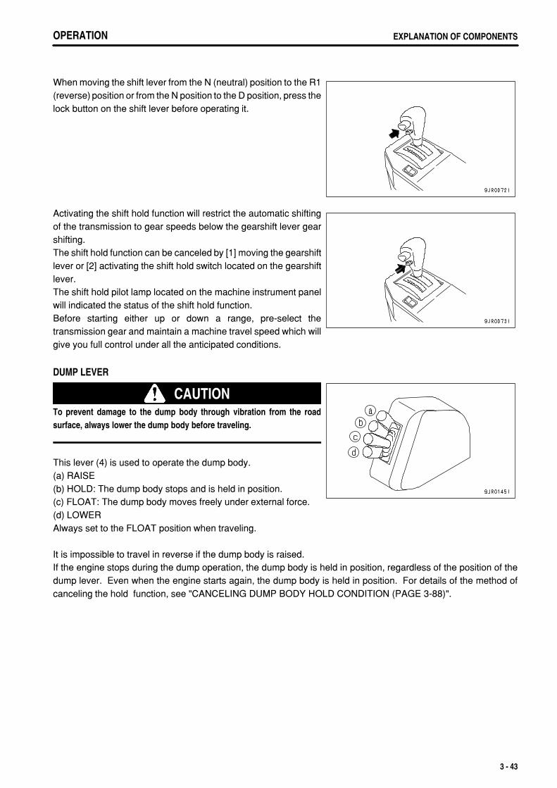
.
OPERATION EXPLANATION OF COMPONENTSOPERATION EXPLANATION OF COMPONENTS
When moving the shift lever from the N (neutral) position to the R1(reverse) position or from the N position to the D position, press thelock button on the shift lever before operating it.
Activating the shift hold function will restrict the automatic shiftingof the transmission to gear speeds below the gearshift lever gearshifting.The shift hold function can be canceled by [1] moving the gearshiftlever or [2] activating the shift hold switch located on the gearshiftlever.The shift hold pilot lamp located on the machine instrument panelwill indicated the status of the shift hold function.Before starting either up or down a range, pre-select thetransmission gear and maintain a machine travel speed which willgive you full control under all the anticipated conditions.
DUMP LEVER
CAUTIONTo prevent damage to the dump body through vibration from the roadsurface, always lower the dump body before traveling.
This lever (4) is used to operate the dump body.(a) RAISE(b) HOLD: The dump body stops and is held in position.(c) FLOAT: The dump body moves freely under external force.(d) LOWERAlways set to the FLOAT position when traveling.
It is impossible to travel in reverse if the dump body is raised.If the engine stops during the dump operation, the dump body is held in position, regardless of the position of thedump lever. Even when the engine starts again, the dump body is held in position. For details of the method ofcanceling the hold function, see "CANCELING DUMP BODY HOLD CONDITION (PAGE 3-88)".
3 - 43
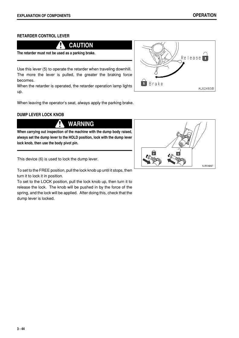
.
OPERATIONEXPLANATION OF COMPONENTS
RETARDER CONTROL LEVER
CAUTIONThe retarder must not be used as a parking brake.
Use this lever (5) to operate the retarder when traveling downhill.The more the lever is pulled, the greater the braking forcebecomes.When the retarder is operated, the retarder operation lamp lightsup.
When leaving the operator's seat, always apply the parking brake.
DUMP LEVER LOCK KNOB
WARNINGWhen carrying out inspection of the machine with the dump body raised,always set the dump lever to the HOLD position, lock with the dump leverlock knob, then use the body pivot pin.
This device (6) is used to lock the dump lever.
To set to the FREE position, pull the lock knob up until it stops, thenturn it to lock it in position.To set to the LOCK position, pull the lock knob up, then turn it torelease the lock. The knob will be pushed in by the force of thespring, and the lock will be applied. After doing this, check that thedump lever is locked.
3 - 44
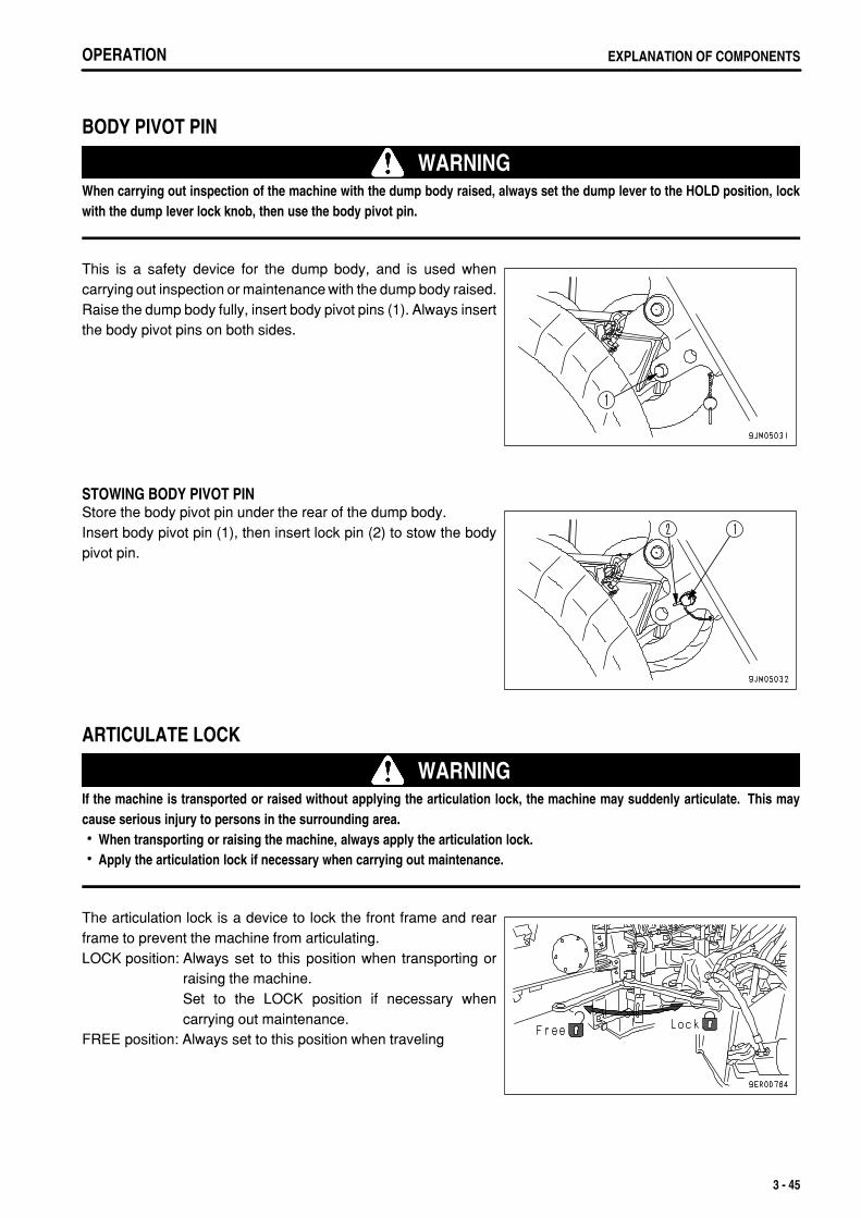
.
OPERATION EXPLANATION OF COMPONENTS
BODY PIVOT PIN
WARNINGWhen carrying out inspection of the machine with the dump body raised, always set the dump lever to the HOLD position, lockwith the dump lever lock knob, then use the body pivot pin.
This is a safety device for the dump body, and is used whencarrying out inspection or maintenance with the dump body raised.Raise the dump body fully, insert body pivot pins (1). Always insertthe body pivot pins on both sides.
STOWING BODY PIVOT PINStore the body pivot pin under the rear of the dump body.Insert body pivot pin (1), then insert lock pin (2) to stow the bodypivot pin.
ARTICULATE LOCK
WARNINGIf the machine is transported or raised without applying the articulation lock, the machine may suddenly articulate. This maycause serious injury to persons in the surrounding area.
When transporting or raising the machine, always apply the articulation lock.Apply the articulation lock if necessary when carrying out maintenance.
The articulation lock is a device to lock the front frame and rearframe to prevent the machine from articulating.LOCK position: Always set to this position when transporting or
raising the machine.Set to the LOCK position if necessary whencarrying out maintenance.
FREE position: Always set to this position when traveling
3 - 45
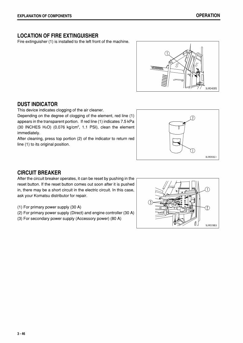
.
OPERATIONEXPLANATION OF COMPONENTS
LOCATION OF FIRE EXTINGUISHERFire extinguisher (1) is installed to the left front of the machine.
DUST INDICATORThis device indicates clogging of the air cleaner.Depending on the degree of clogging of the element, red line (1)appears in the transparent portion. If red line (1) indicates 7.5 kPa(30 INCHES H2O) (0.076 kg/cm2, 1.1 PSI), clean the elementimmediately.After cleaning, press top portion (2) of the indicator to return redline (1) to its original position.
CIRCUIT BREAKERAfter the circuit breaker operates, it can be reset by pushing in thereset button. If the reset button comes out soon after it is pushedin, there may be a short circuit in the electric circuit. In this case,ask your Komatsu distributor for repair.
(1) For primary power supply (30 A)(2) For primary power supply (Direct) and engine controller (30 A)(3) For secondary power supply (Accessory power) (80 A)
3 - 46
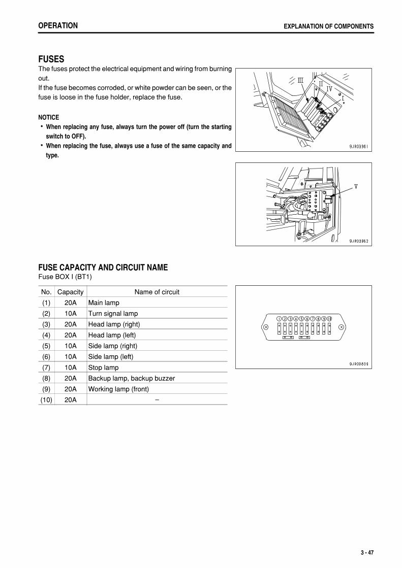
.
OPERATION EXPLANATION OF COMPONENTS
FUSESThe fuses protect the electrical equipment and wiring from burningout.If the fuse becomes corroded, or white powder can be seen, or thefuse is loose in the fuse holder, replace the fuse.
NOTICEWhen replacing any fuse, always turn the power off (turn the startingswitch to OFF).When replacing the fuse, always use a fuse of the same capacity andtype.
FUSE CAPACITY AND CIRCUIT NAMEFuse BOX I (BT1)
No. Capacity Name of circuit
(1) 20A Main lamp
(2) 10A Turn signal lamp
(3) 20A Head lamp (right)
(4) 20A Head lamp (left)
(5) 10A Side lamp (right)
(6) 10A Side lamp (left)
(7) 10A Stop lamp
(8) 20A Backup lamp, backup buzzer
(9) 20A Working lamp (front)
(10) 20A –
3 - 47
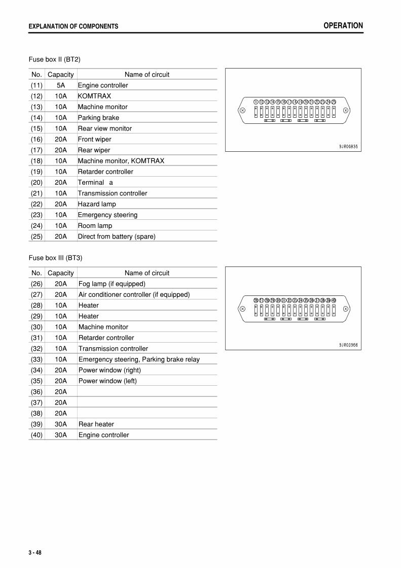
.
OPERATIONEXPLANATION OF COMPONENTS
Fuse box II (BT2)
No. Capacity Name of circuit
(11) 5A Engine controller
(12) 10A KOMTRAX
(13) 10A Machine monitor
(14) 10A Parking brake
(15) 10A Rear view monitor
(16) 20A Front wiper
(17) 20A Rear wiper
(18) 10A Machine monitor, KOMTRAX
(19) 10A Retarder controller
(20) 20A Terminal ‚a
(21) 10A Transmission controller
(22) 20A Hazard lamp
(23) 10A Emergency steering
(24) 10A Room lamp
(25) 20A Direct from battery (spare)
Fuse box III (BT3)
No. Capacity Name of circuit
(26) 20A Fog lamp (if equipped)
(27) 20A Air conditioner controller (if equipped)
(28) 10A Heater
(29) 10A Heater
(30) 10A Machine monitor
(31) 10A Retarder controller
(32) 10A Transmission controller
(33) 10A Emergency steering, Parking brake relay
(34) 20A Power window�(right)
(35) 20A Power window�(left)
(36) 20A
(37) 20A
(38) 20A
(39) 30A Rear heater
(40) 30A Engine controller
3 - 48
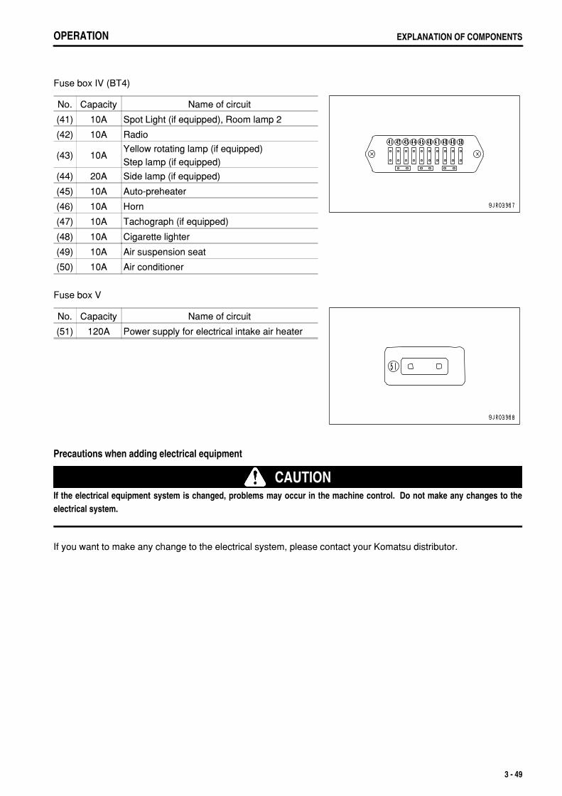
.
OPERATION EXPLANATION OF COMPONENTS
Fuse box IV (BT4)
No. Capacity Name of circuit
(41) 10A Spot Light (if equipped), Room lamp 2
(42) 10A Radio
(43) 10AYellow rotating lamp (if equipped)Step lamp (if equipped)
(44) 20A Side lamp (if equipped)
(45) 10A Auto-preheater
(46) 10A Horn
(47) 10A Tachograph (if equipped)
(48) 10A Cigarette lighter
(49) 10A Air suspension seat
(50) 10A Air conditioner
Fuse box V
No. Capacity Name of circuit
(51) 120A Power supply for electrical intake air heater
Precautions when adding electrical equipment
CAUTIONIf the electrical equipment system is changed, problems may occur in the machine control. Do not make any changes to theelectrical system.
If you want to make any change to the electrical system, please contact your Komatsu distributor.
3 - 49
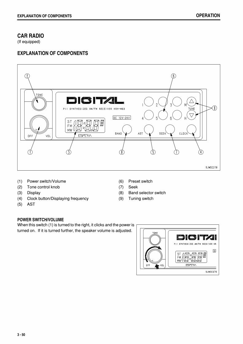
.
OPERATIONEXPLANATION OF COMPONENTS
CAR RADIO(If equipped)
EXPLANATION OF COMPONENTS
(1)(2)(3)(4)(5)
Power switch/VolumeTone control knobDisplayClock button/Displaying frequencyAST
(6)(7)(8)(9)
Preset switchSeekBand selector switchTuning switch
POWER SWITCH/VOLUMEWhen this switch (1) is turned to the right, it clicks and the power isturned on. If it is turned further, the speaker volume is adjusted.
3 - 50
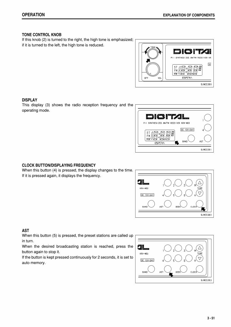
.
OPERATION EXPLANATION OF COMPONENTS
TONE CONTROL KNOBIf this knob (2) is turned to the right, the high tone is emphasized;if it is turned to the left, the high tone is reduced.
DISPLAYThis display (3) shows the radio reception frequency and theoperating mode.
CLOCK BUTTON/DISPLAYING FREQUENCYWhen this button (4) is pressed, the display changes to the time.If it is pressed again, it displays the frequency.
ASTWhen this button (5) is pressed, the preset stations are called upin turn.When the desired broadcasting station is reached, press thebutton again to stop it.If the button is kept pressed continuously for 2 seconds, it is set toauto memory.
3 - 51
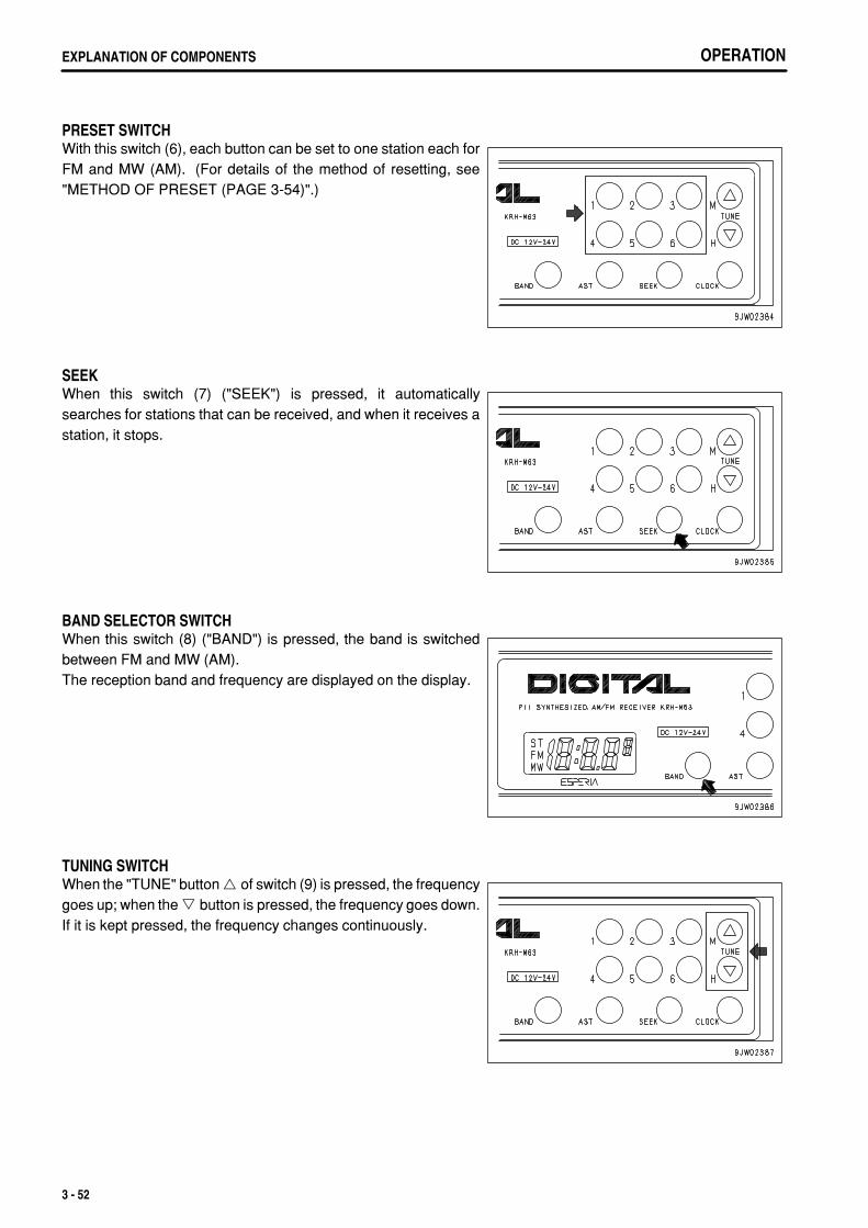
.
OPERATIONEXPLANATION OF COMPONENTS
PRESET SWITCHWith this switch (6), each button can be set to one station each forFM and MW (AM). (For details of the method of resetting, see"METHOD OF PRESET (PAGE 3-54)".)
SEEKWhen this switch (7) ("SEEK") is pressed, it automaticallysearches for stations that can be received, and when it receives astation, it stops.
BAND SELECTOR SWITCHWhen this switch (8) ("BAND") is pressed, the band is switchedbetween FM and MW (AM).The reception band and frequency are displayed on the display.
TUNING SWITCHWhen the "TUNE" button of switch (9) is pressed, the frequencygoes up; when the button is pressed, the frequency goes down.If it is kept pressed, the frequency changes continuously.
3 - 52

.
OPERATION EXPLANATION OF COMPONENTS
METHOD OF OPERATION
LISTENING TO RADIO 1. This switches on power (1) for the radio. 2. "BAND" switch (2) is used to select MW (AM) or FM. 3. Use the preset switch or tuning switch (3) to select the station. 4. Adjust the volume and tone as desired. 5. To turn the radio OFF, turn VOL knob (1) to the left until a click
is heard.
METHOD OF AUTOMATIC TUNINGWhen the "SEEK" switch is pressed, it moves up to higherfrequencies and when it finds a station that can be received, itstops automatically.
METHOD OF MANUAL TUNINGWhen the TUNE button is pressed, the frequency goes up;when the button is pressed, the frequency goes down. If it iskept pressed, the frequency changes continuously.
3 - 53
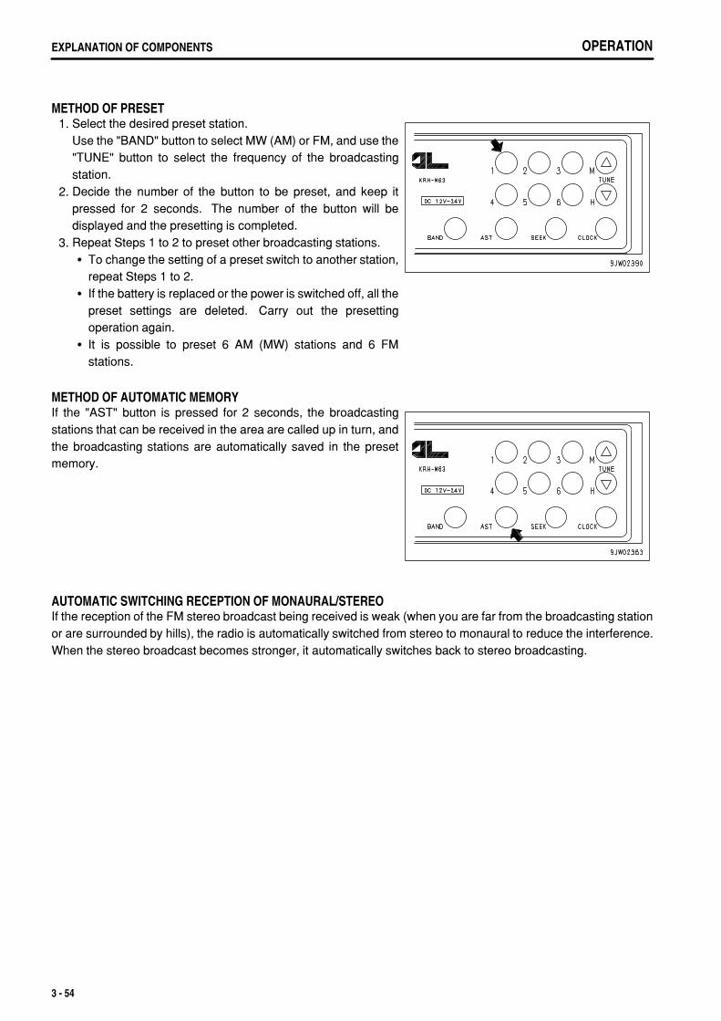
.
OPERATIONEXPLANATION OF COMPONENTS
METHOD OF PRESET 1. Select the desired preset station.
Use the "BAND" button to select MW (AM) or FM, and use the"TUNE" button to select the frequency of the broadcastingstation.
2. Decide the number of the button to be preset, and keep itpressed for 2 seconds. The number of the button will bedisplayed and the presetting is completed.
3. Repeat Steps 1 to 2 to preset other broadcasting stations.To change the setting of a preset switch to another station,repeat Steps 1 to 2.If the battery is replaced or the power is switched off, all thepreset settings are deleted. Carry out the presettingoperation again.It is possible to preset 6 AM (MW) stations and 6 FMstations.
METHOD OF AUTOMATIC MEMORYIf the "AST" button is pressed for 2 seconds, the broadcastingstations that can be received in the area are called up in turn, andthe broadcasting stations are automatically saved in the presetmemory.
AUTOMATIC SWITCHING RECEPTION OF MONAURAL/STEREOIf the reception of the FM stereo broadcast being received is weak (when you are far from the broadcasting stationor are surrounded by hills), the radio is automatically switched from stereo to monaural to reduce the interference.When the stereo broadcast becomes stronger, it automatically switches back to stereo broadcasting.
3 - 54
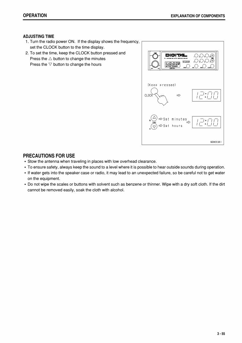
.
OPERATION EXPLANATION OF COMPONENTS
ADJUSTING TIME 1. Turn the radio power ON. If the display shows the frequency,
set the CLOCK button to the time display. 2. To set the time, keep the CLOCK button pressed and
Press the button to change the minutesPress the button to change the hours
PRECAUTIONS FOR USEStow the antenna when traveling in places with low overhead clearance.To ensure safety, always keep the sound to a level where it is possible to hear outside sounds during operation.If water gets into the speaker case or radio, it may lead to an unexpected failure, so be careful not to get wateron the equipment.Do not wipe the scales or buttons with solvent such as benzene or thinner. Wipe with a dry soft cloth. If the dirtcannot be removed easily, soak the cloth with alcohol.
3 - 55
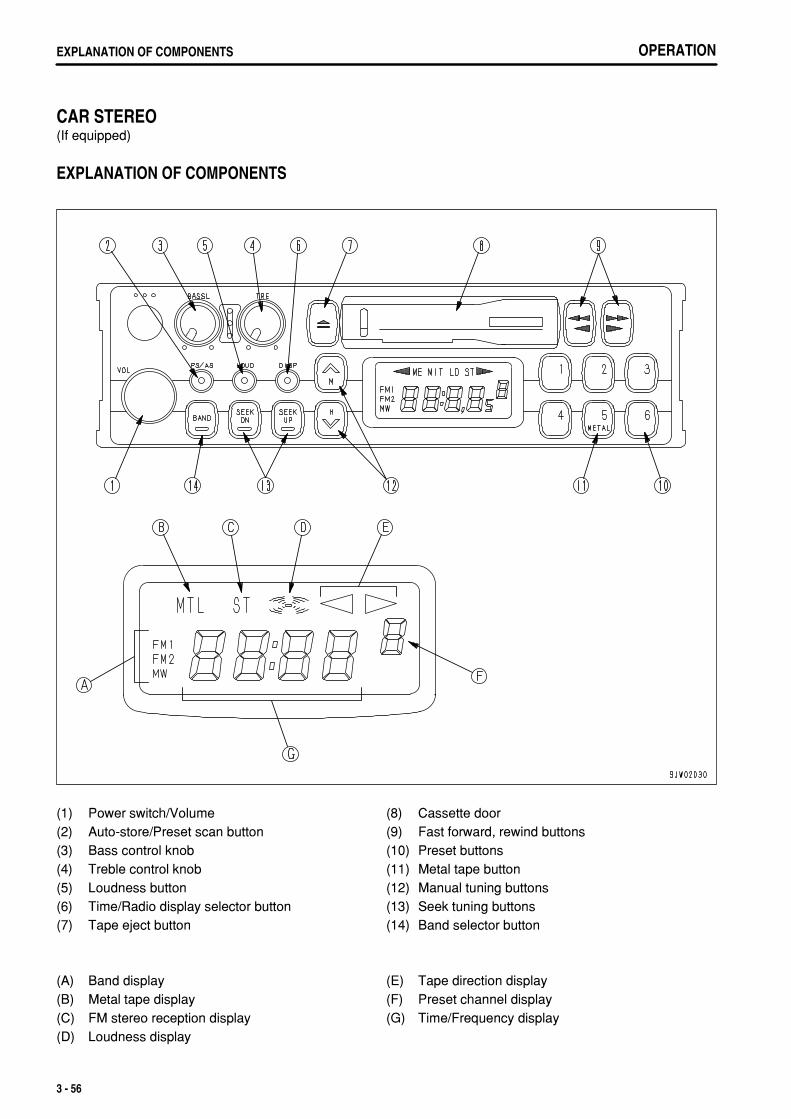
.
OPERATIONEXPLANATION OF COMPONENTS
CAR STEREO(If equipped)
EXPLANATION OF COMPONENTS
(1)(2)(3)(4)(5)(6)(7)
Power switch/VolumeAuto-store/Preset scan buttonBass control knobTreble control knobLoudness buttonTime/Radio display selector buttonTape eject button
(8)(9)(10)(11)(12)(13)(14)
Cassette doorFast forward, rewind buttonsPreset buttonsMetal tape buttonManual tuning buttonsSeek tuning buttonsBand selector button
(A)(B)(C)(D)
Band displayMetal tape displayFM stereo reception displayLoudness display
(E)(F)(G)
Tape direction displayPreset channel displayTime/Frequency display
3 - 56
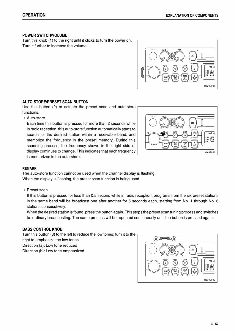
.
OPERATION EXPLANATION OF COMPONENTS
POWER SWITCH/VOLUMETurn this knob (1) to the right until it clicks to turn the power on.Turn it further to increase the volume.
AUTO-STORE/PRESET SCAN BUTTONUse this button (2) to actuate the preset scan and auto-storefunctions.
Auto-storeEach time this button is pressed for more than 2 seconds whilein radio reception, this auto-store function automatically starts tosearch for the desired station within a receivable band, andmemorize the frequency in the preset memory. During thisscanning process, the frequency shown in the right side ofdisplay continues to change. This indicates that each frequencyis memorized in the auto-store.
REMARKThe auto-store function cannot be used when the channel display is flashing.When the display is flashing, the preset scan function is being used.
Preset scanIf this button is pressed for less than 0.5 second while in radio reception, programs from the six preset stationsin the same band will be broadcast one after another for 5 seconds each, starting from No. 1 through No. 6stations consecutively.When the desired station is found, press the button again. This stops the preset scan tuning process and switchesto ordinary broadcasting. The same process will be repeated continuously until the button is pressed again.
BASS CONTROL KNOBTurn this button (3) to the left to reduce the low tones; turn it to theright to emphasize the low tones.Direction (a): Low tone reducedDirection (b): Low tone emphasized
3 - 57
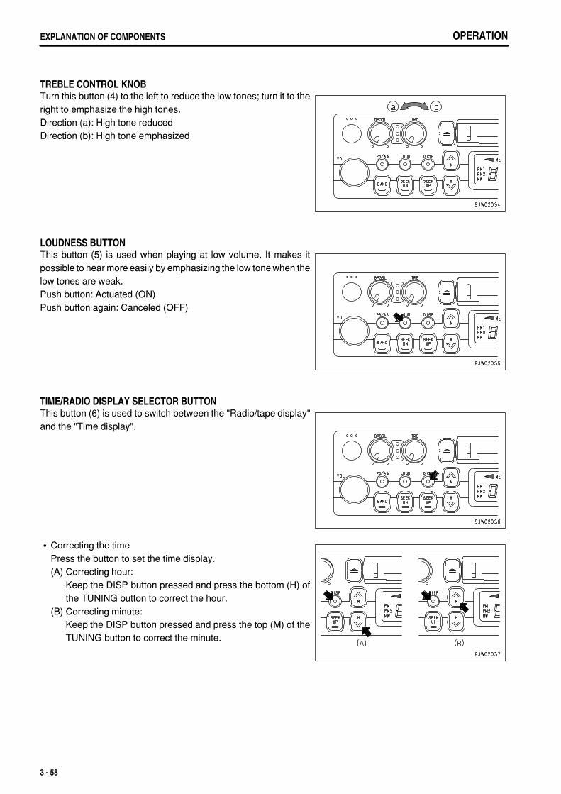
.
OPERATIONEXPLANATION OF COMPONENTS
TREBLE CONTROL KNOBTurn this button (4) to the left to reduce the low tones; turn it to theright to emphasize the high tones.Direction (a): High tone reducedDirection (b): High tone emphasized
LOUDNESS BUTTONThis button (5) is used when playing at low volume. It makes itpossible to hear more easily by emphasizing the low tone when thelow tones are weak.Push button: Actuated (ON)Push button again: Canceled (OFF)
TIME/RADIO DISPLAY SELECTOR BUTTONThis button (6) is used to switch between the "Radio/tape display"and the "Time display".
Correcting the timePress the button to set the time display.(A) Correcting hour:
Keep the DISP button pressed and press the bottom (H) ofthe TUNING button to correct the hour.
(B) Correcting minute:Keep the DISP button pressed and press the top (M) of theTUNING button to correct the minute.
3 - 58
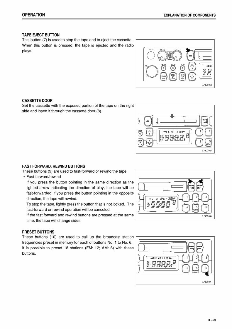
.
OPERATION EXPLANATION OF COMPONENTS
TAPE EJECT BUTTONThis button (7) is used to stop the tape and to eject the cassette.When this button is pressed, the tape is ejected and the radioplays.
CASSETTE DOORSet the cassette with the exposed portion of the tape on the rightside and insert it through the cassette door (8).
FAST FORWARD, REWIND BUTTONSThese buttons (9) are used to fast-forward or rewind the tape.
Fast-forward/rewindIf you press the button pointing in the same direction as thelighted arrow indicating the direction of play, the tape will befast-forwarded; if you press the button pointing in the oppositedirection, the tape will rewind.To stop the tape, lightly press the button that is not locked. Thefast-forward or rewind operation will be canceled.If the fast forward and rewind buttons are pressed at the sametime, the tape will change sides.
PRESET BUTTONSThese buttons (10) are used to call up the broadcast stationfrequencies preset in memory for each of buttons No. 1 to No. 6.It is possible to preset 18 stations (FM: 12; AM: 6) with thesebuttons.
3 - 59
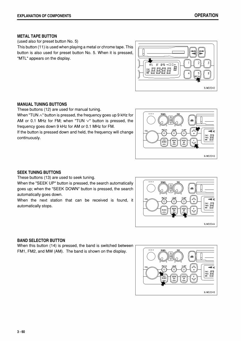
.
OPERATIONEXPLANATION OF COMPONENTS
METAL TAPE BUTTON(used also for preset button No. 5)This button (11) is used when playing a metal or chrome tape. Thisbutton is also used for preset button No. 5. When it is pressed,"MTL" appears on the display.
MANUAL TUNING BUTTONSThese buttons (12) are used for manual tuning.When "TUN ∧" button is pressed, the frequency goes up 9 kHz forAM or 0.1 MHz for FM; when "TUN ∨" button is pressed, thefrequency goes down 9 kHz for AM or 0.1 MHz for FM.If the button is pressed down and held, the frequency will changecontinuously.
SEEK TUNING BUTTONSThese buttons (13) are used to seek tuning.When the "SEEK UP" button is pressed, the search automaticallygoes up; when the "SEEK DOWN" button is pressed, the searchautomatically goes down.When the next station that can be received is found, itautomatically stops.
BAND SELECTOR BUTTONWhen this button (14) is pressed, the band is switched betweenFM1, FM2, and MW (AM). The band is shown on the display.
3 - 60

.
OPERATION EXPLANATION OF COMPONENTS
METHOD OF OPERATION
METHOD OF SETTING PRESET BUTTONSTo listen to a preset station, use band selector button (1) to selectAM, FM1, or FM2, then press the preset switch number to listen tothe desired station.It is possible to preset six AM stations and 12 FM stations (FM1: 6,FM2: 6).
1. If you are playing a cassette, press the tape eject button to stopthe tape.
2. Select the station to be preset.Use band selector button (1) to select MW (AM), FM1, or FM2,then use the manual tuning button to select the frequency ofthe broadcasting station.
3. Press manual memory button (2) or seek tuning button (3). 4. Press preset button (4) of the number to be preset for 2
seconds while the frequency display is being shown on thedisplay. (The preset channel and frequency are displayed andthe presetting is completed).
5. Repeat Steps 2 to 4 to preset other stations.
REMARKUse Steps 2 to 4 also when changing the setting of a preset switch to another station.When the power is disconnected, such as when the battery is replaced, all the settings are deleted, so preset thestations again.
MANUAL MEMORY BUTTONSelect the station to be preset with manual tuning button (1) orseek tuning button (2), then keep button No.1 to button No.6 ofbutton (3) pressed for 2 seconds while the frequency is beingdisplayed to preset the station.
3 - 61
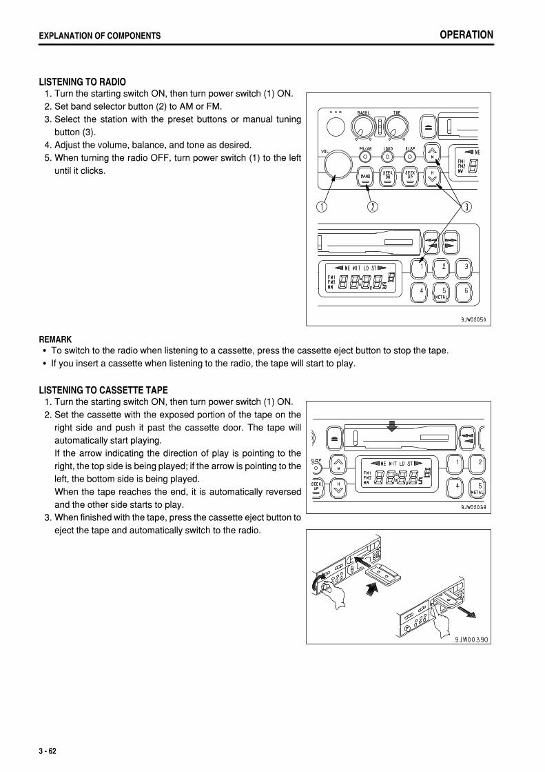
.
OPERATIONEXPLANATION OF COMPONENTS
LISTENING TO RADIO 1. Turn the starting switch ON, then turn power switch (1) ON. 2. Set band selector button (2) to AM or FM. 3. Select the station with the preset buttons or manual tuning
button (3). 4. Adjust the volume, balance, and tone as desired. 5. When turning the radio OFF, turn power switch (1) to the left
until it clicks.
REMARKTo switch to the radio when listening to a cassette, press the cassette eject button to stop the tape.If you insert a cassette when listening to the radio, the tape will start to play.
LISTENING TO CASSETTE TAPE 1. Turn the starting switch ON, then turn power switch (1) ON. 2. Set the cassette with the exposed portion of the tape on the
right side and push it past the cassette door. The tape willautomatically start playing.If the arrow indicating the direction of play is pointing to theright, the top side is being played; if the arrow is pointing to theleft, the bottom side is being played.When the tape reaches the end, it is automatically reversedand the other side starts to play.
3. When finished with the tape, press the cassette eject button toeject the tape and automatically switch to the radio.
3 - 62
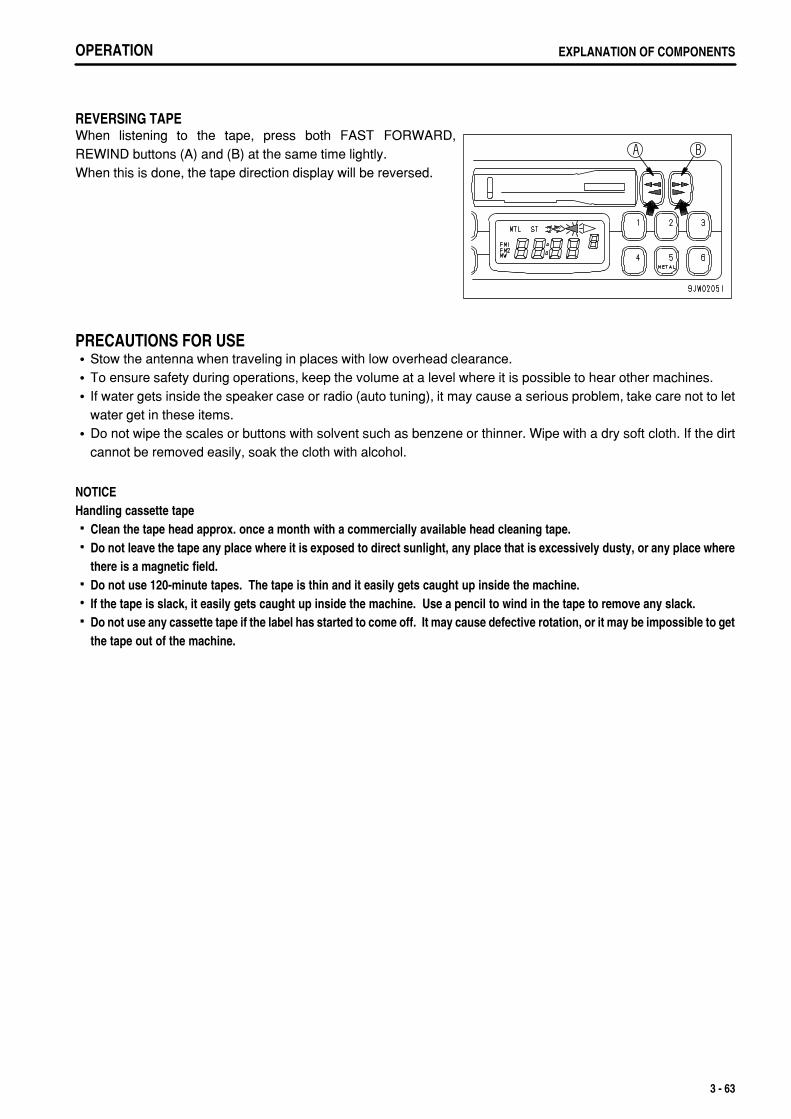
.
OPERATION EXPLANATION OF COMPONENTS
REVERSING TAPEWhen listening to the tape, press both FAST FORWARD,REWIND buttons (A) and (B) at the same time lightly.When this is done, the tape direction display will be reversed.
PRECAUTIONS FOR USEStow the antenna when traveling in places with low overhead clearance.To ensure safety during operations, keep the volume at a level where it is possible to hear other machines.If water gets inside the speaker case or radio (auto tuning), it may cause a serious problem, take care not to letwater get in these items.Do not wipe the scales or buttons with solvent such as benzene or thinner. Wipe with a dry soft cloth. If the dirtcannot be removed easily, soak the cloth with alcohol.
NOTICEHandling cassette tape
Clean the tape head approx. once a month with a commercially available head cleaning tape.Do not leave the tape any place where it is exposed to direct sunlight, any place that is excessively dusty, or any place wherethere is a magnetic field.Do not use 120-minute tapes. The tape is thin and it easily gets caught up inside the machine.If the tape is slack, it easily gets caught up inside the machine. Use a pencil to wind in the tape to remove any slack.Do not use any cassette tape if the label has started to come off. It may cause defective rotation, or it may be impossible to getthe tape out of the machine.
3 - 63
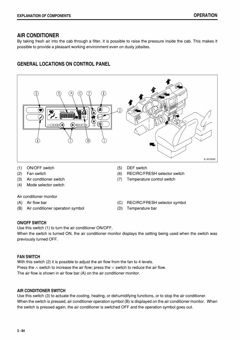
.
OPERATIONEXPLANATION OF COMPONENTS
AIR CONDITIONERBy taking fresh air into the cab through a filter, it is possible to raise the pressure inside the cab. This makes itpossible to provide a pleasant working environment even on dusty jobsites.
GENERAL LOCATIONS ON CONTROL PANEL
(1)(2)(3)(4)
ON/OFF switchFan switchAir conditioner switchMode selector switch
(5)(6)(7)
DEF switchRECIRC/FRESH selector switchTemperature control switch
Air conditioner monitor
(A)(B)
Air flow barAir conditioner operation symbol
(C)(D)
RECIRC/FRESH selector symbolTemperature bar
ON/OFF SWITCHUse this switch (1) to turn the air conditioner ON/OFF.When the switch is turned ON, the air conditioner monitor displays the setting being used when the switch waspreviously turned OFF.
FAN SWITCHWith this switch (2) it is possible to adjust the air flow from the fan to 4 levels.Press the ∧ switch to increase the air flow; press the ∨ switch to reduce the air flow.The air flow is shown in air flow bar (A) on the air conditioner monitor.
AIR CONDITIONER SWITCHUse this switch (3) to actuate the cooling, heating, or dehumidifying functions, or to stop the air conditioner.When the switch is pressed, air conditioner operation symbol (B) is displayed on the air conditioner monitor. Whenthe switch is pressed again, the air conditioner is switched OFF and the operation symbol goes out.
3 - 64
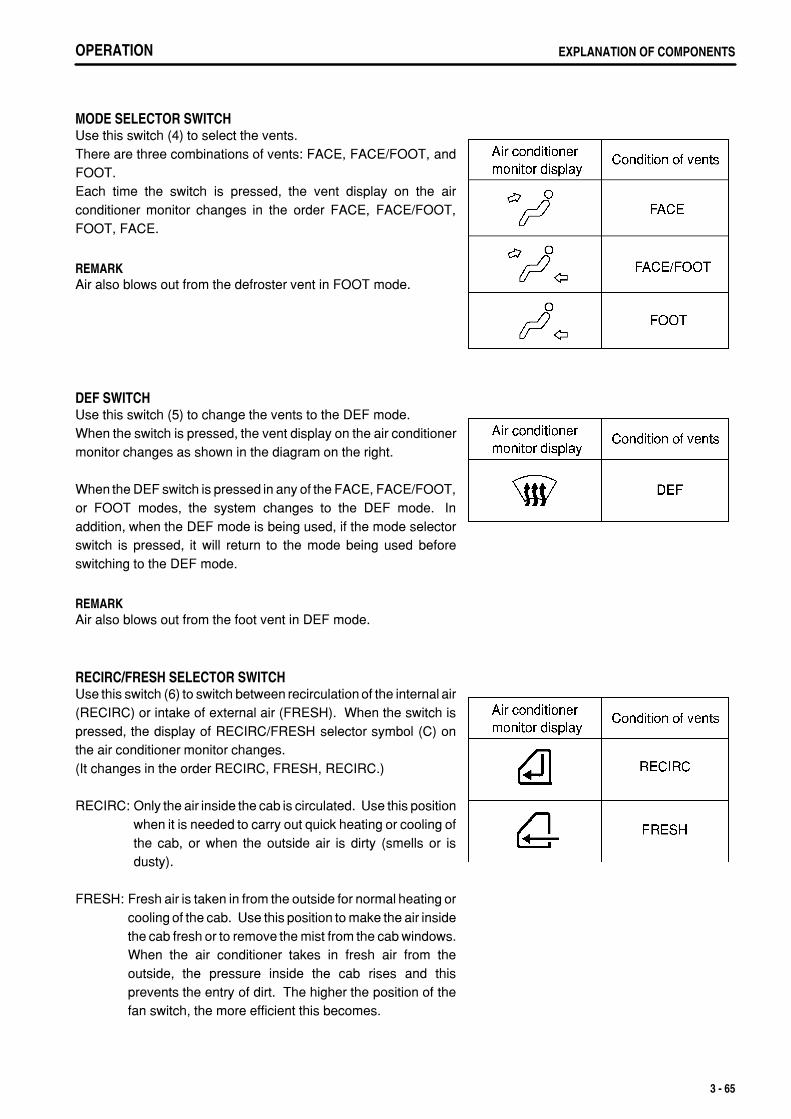
.
OPERATION EXPLANATION OF COMPONENTS
MODE SELECTOR SWITCHUse this switch (4) to select the vents.There are three combinations of vents: FACE, FACE/FOOT, andFOOT.Each time the switch is pressed, the vent display on the airconditioner monitor changes in the order FACE, FACE/FOOT,FOOT, FACE.
REMARKAir also blows out from the defroster vent in FOOT mode.
DEF SWITCHUse this switch (5) to change the vents to the DEF mode.When the switch is pressed, the vent display on the air conditionermonitor changes as shown in the diagram on the right.
When the DEF switch is pressed in any of the FACE, FACE/FOOT,or FOOT modes, the system changes to the DEF mode. Inaddition, when the DEF mode is being used, if the mode selectorswitch is pressed, it will return to the mode being used beforeswitching to the DEF mode.
REMARKAir also blows out from the foot vent in DEF mode.
RECIRC/FRESH SELECTOR SWITCHUse this switch (6) to switch between recirculation of the internal air(RECIRC) or intake of external air (FRESH). When the switch ispressed, the display of RECIRC/FRESH selector symbol (C) onthe air conditioner monitor changes.(It changes in the order RECIRC, FRESH, RECIRC.)
RECIRC: Only the air inside the cab is circulated. Use this positionwhen it is needed to carry out quick heating or cooling ofthe cab, or when the outside air is dirty (smells or isdusty).
FRESH: Fresh air is taken in from the outside for normal heating orcooling of the cab. Use this position to make the air insidethe cab fresh or to remove the mist from the cab windows.When the air conditioner takes in fresh air from theoutside, the pressure inside the cab rises and thisprevents the entry of dirt. The higher the position of thefan switch, the more efficient this becomes.
3 - 65
.
OPERATIONEXPLANATION OF COMPONENTS
TEMPERATURE CONTROL SWITCHUse this switch (7) to adjust the temperature of the air blowing out from the vents. The adjustment can be made to8 levels from low temperature to high temperature.The temperature of the air blowing out from the vents is displayed on temperature bar (D) on the monitor. The lowerthe number of segments lighted up on the bar, the lower the temperature is.
Press the > switch to raise the temperature; press the < switch to lower the temperature.
Even when the starting switch is turned OFF, the settings of each mode are retained in memory. However, in thefollowing cases, the settings must be made again.
When the machine has not been used for more than seven daysWhen the battery voltage is extremely lowWhen there is abnormal interference from the surrounding areaWhen the fan switch has been turned OFF (only the air conditioner switch setting is retained)
3 - 66
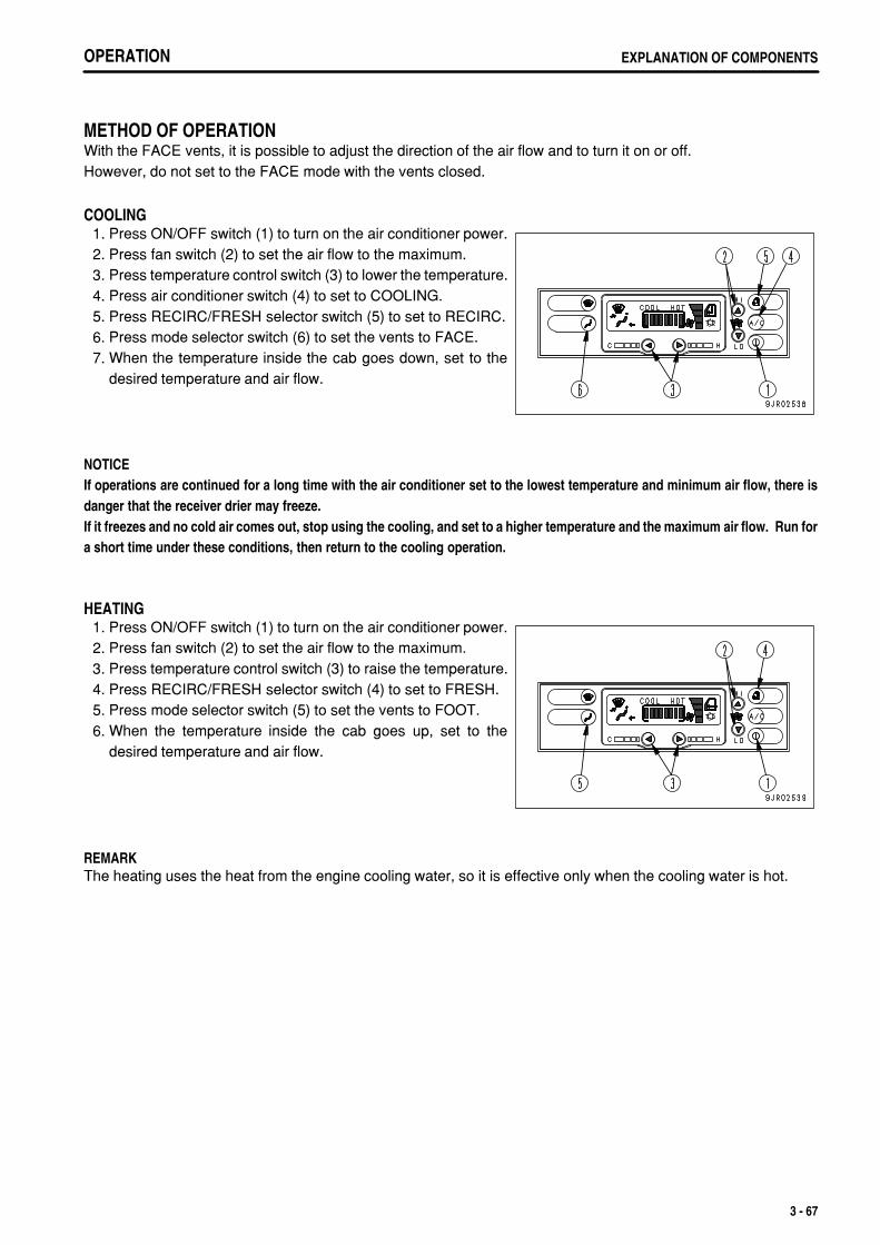
.
OPERATION EXPLANATION OF COMPONENTS
METHOD OF OPERATIONWith the FACE vents, it is possible to adjust the direction of the air flow and to turn it on or off.However, do not set to the FACE mode with the vents closed.
COOLING 1. Press ON/OFF switch (1) to turn on the air conditioner power. 2. Press fan switch (2) to set the air flow to the maximum. 3. Press temperature control switch (3) to lower the temperature. 4. Press air conditioner switch (4) to set to COOLING. 5. Press RECIRC/FRESH selector switch (5) to set to RECIRC. 6. Press mode selector switch (6) to set the vents to FACE. 7. When the temperature inside the cab goes down, set to the
desired temperature and air flow.
NOTICEIf operations are continued for a long time with the air conditioner set to the lowest temperature and minimum air flow, there isdanger that the receiver drier may freeze.If it freezes and no cold air comes out, stop using the cooling, and set to a higher temperature and the maximum air flow. Run fora short time under these conditions, then return to the cooling operation.
HEATING 1. Press ON/OFF switch (1) to turn on the air conditioner power. 2. Press fan switch (2) to set the air flow to the maximum. 3. Press temperature control switch (3) to raise the temperature. 4. Press RECIRC/FRESH selector switch (4) to set to FRESH. 5. Press mode selector switch (5) to set the vents to FOOT. 6. When the temperature inside the cab goes up, set to the
desired temperature and air flow.
REMARKThe heating uses the heat from the engine cooling water, so it is effective only when the cooling water is hot.
3 - 67
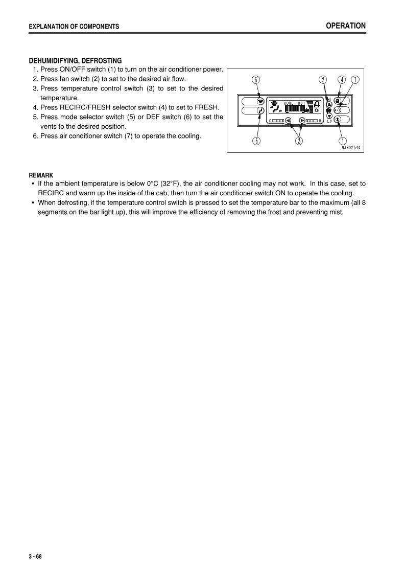
.
OPERATIONEXPLANATION OF COMPONENTS
DEHUMIDIFYING, DEFROSTING 1. Press ON/OFF switch (1) to turn on the air conditioner power. 2. Press fan switch (2) to set to the desired air flow. 3. Press temperature control switch (3) to set to the desired
temperature. 4. Press RECIRC/FRESH selector switch (4) to set to FRESH. 5. Press mode selector switch (5) or DEF switch (6) to set the
vents to the desired position. 6. Press air conditioner switch (7) to operate the cooling.
REMARKIf the ambient temperature is below 0°C (32°F), the air conditioner cooling may not work. In this case, set toRECIRC and warm up the inside of the cab, then turn the air conditioner switch ON to operate the cooling.When defrosting, if the temperature control switch is pressed to set the temperature bar to the maximum (all 8segments on the bar light up), this will improve the efficiency of removing the frost and preventing mist.
3 - 68
.
OPERATION EXPLANATION OF COMPONENTS
PRECAUTIONS WHEN USING AIR CONDITIONERTo prevent putting any excessive load on the engine or compressor, turn the air conditioner ON only when theengine is running.
Carry out ventilation from time to time when using the cooling.When turning the cooling on, if the temperature inside the cab is high, open the doors and windows to bring infresh air before starting the air conditioner.If you smoke when using the cooling, your eyes may sting. If this happens, switch temporarily to cooling andventilation to remove the smoke.When using the air conditioner for a long time, carry out ventilation and cooling once every hour.
Be careful not to cool the cab too much.For reasons of health, the optimum setting for cooling is considered to be when it feels slightly cool (5 or 6°C (9 or10.8°F) lower than the ambient temperature) when you enter the cab. Do not make the temperature inside the cabtoo low or direct the air flow directly onto your skin.Be extremely careful to select the appropriate temperature.
When cooling is not being used (off-season)To prevent leakage of the refrigerant from the air conditioner cooling circuit, operate the air conditioner for severalminutes 2 or 3 times a month during the off-season. If the air conditioner is left for a long time when the refrigerantis leaking, it may cause internal rust.
INSPECTION AND MAINTENANCE
Even when not using the air conditioner, run the compressor at low speed for several minutes once a week toprevent the loss of the oil film at various parts of the compressor. (Run the engine at low speed and set thetemperature control lever to the central position.)
Clean the air filter and check the refrigerant. For details, see "CLEAN AIR CONDITIONER AIR FILTER (PAGE4-29)" and "CHECK REFRIGERANT (GAS) LEVEL (PAGE 4-30)".
To enable the air conditioner to perform to the full and to maintain a pleasant working environment, always contactyour Komatsu distributor to have the air conditioner refilled with refrigerant and to carry out other checks.
3 - 69
.
OPERATIONOPERATION
OPERATION
CHECK BEFORE STARTING ENGINE
WALK-AROUND CHECKBefore starting the engine, look around the machine and under the machine to check for loose nuts or bolts, orleakage of oil, fuel, or coolant, and check the condition of the hydraulic system.Check also for loose wiring, play, and accumulation of dust in places that get very hot and are exposed to extremelyhigh temperatures.
WARNINGAlways hang the warning tag from the shift lever.Leakage of oil or fuel, or accumulation of flammable material around the battery or high temperature parts of the engine, suchas the engine muffler or turbocharger, may cause fire. Check carefully, and if any problem is found, repair it or contact yourKomatsu distributor.
Always carry out the following items before starting the engine each day.
1. Check the dump body, frame, tires, cylinders, linkage, and hoses for cracks or excessive wear or play.Check the dump body, frame, tires, cylinders, linkage, and hoses for cracks or excessive wear or play, and carry outrepairs if any problem is found.
2. Remove dirt from around engine, battery, radiator, and aftercooler.Check that there is no dirt or dust accumulated around the engine, radiator or aftercooler. Check also that there isno flammable material (dry leaves, twigs, etc.) accumulated around the battery, or engine, muffler, turbocharger, orother high temperature parts of the engine. Remove any dirt or flammable materials that are found.
3. Check for leakage of water or oil around engine�Check that there is no oil leakage from the engine or coolant leakage from the cooling system. If any problem isfound, repair it.
4. Check for oil leakage from transmission case, differential case, final drive case, hydraulic tank, brake control oiltank, hoses, and joints
Check that there is no oil leakage. If any problem is found, repair the place where the oil is leaking.Check for leakage of oil from the undercover. Check the ground for traces of oil leakage.
5. Check for loose air cleaner mounting bolts.Check for the loose bolts. If loose, tighten them.
6. Check dump body mount rubberCheck for any cracks, embedded foreign objects, or loose bolts.
7. Check for damage to handrail, loose boltsRepair any damage and tighten any loose bolts.
8. Check for damage to gauges, lamps on the instrument panel and loose bolts.Check for damage to the panel, gauges and lamps. If any problem is found, replace the parts. Clean off any dirt onthe surface. Tighten any loose bolts.
3 - 70
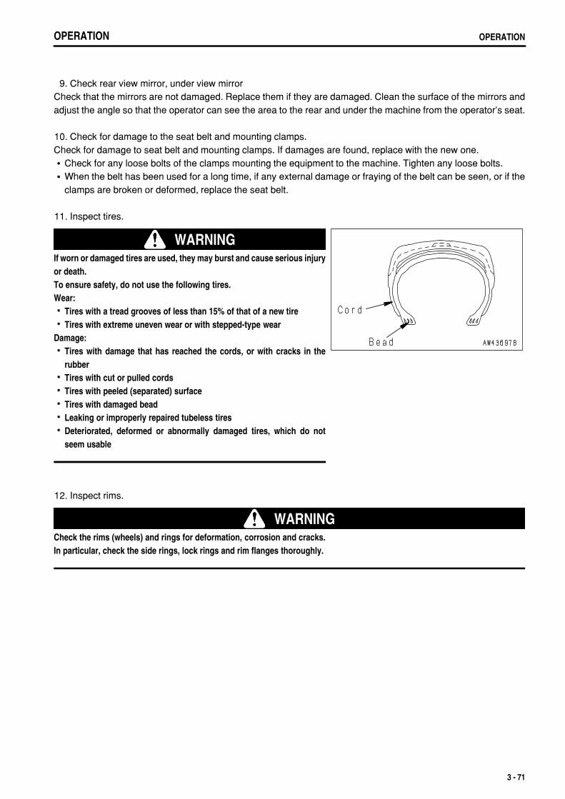
.
OPERATION OPERATION
9. Check rear view mirror, under view mirrorCheck that the mirrors are not damaged. Replace them if they are damaged. Clean the surface of the mirrors andadjust the angle so that the operator can see the area to the rear and under the machine from the operator's seat.
10. Check for damage to the seat belt and mounting clamps.Check for damage to seat belt and mounting clamps. If damages are found, replace with the new one.
Check for any loose bolts of the clamps mounting the equipment to the machine. Tighten any loose bolts.When the belt has been used for a long time, if any external damage or fraying of the belt can be seen, or if theclamps are broken or deformed, replace the seat belt.
11. Inspect tires.
WARNINGIf worn or damaged tires are used, they may burst and cause serious injuryor death.To ensure safety, do not use the following tires.Wear:
Tires with a tread grooves of less than 15% of that of a new tireTires with extreme uneven wear or with stepped-type wear
Damage:Tires with damage that has reached the cords, or with cracks in therubberTires with cut or pulled cordsTires with peeled (separated) surfaceTires with damaged beadLeaking or improperly repaired tubeless tiresDeteriorated, deformed or abnormally damaged tires, which do notseem usable
12. Inspect rims.
WARNINGCheck the rims (wheels) and rings for deformation, corrosion and cracks.In particular, check the side rings, lock rings and rim flanges thoroughly.
3 - 71
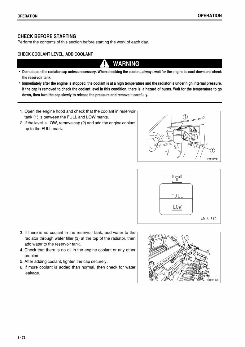
.
OPERATIONOPERATION
CHECK BEFORE STARTINGPerform the contents of this section before starting the work of each day.
CHECK COOLANT LEVEL, ADD COOLANT
WARNINGDo not open the radiator cap unless necessary. When checking the coolant, always wait for the engine to cool down and checkthe reservoir tank.Immediately after the engine is stopped, the coolant is at a high temperature and the radiator is under high internal pressure.If the cap is removed to check the coolant level in this condition, there is a hazard of burns. Wait for the temperature to godown, then turn the cap slowly to release the pressure and remove it carefully.
1. Open the engine hood and check that the coolant in reservoirtank (1) is between the FULL and LOW marks.
2. If the level is LOW, remove cap (2) and add the engine coolantup to the FULL mark.
3. If there is no coolant in the reservoir tank, add water to theradiator through water filler (3) at the top of the radiator, thenadd water to the reservoir tank.
4. Check that there is no oil in the engine coolant or any otherproblem.
5. After adding coolant, tighten the cap securely. 6. If more coolant is added than normal, then check for water
leakage.
3 - 72
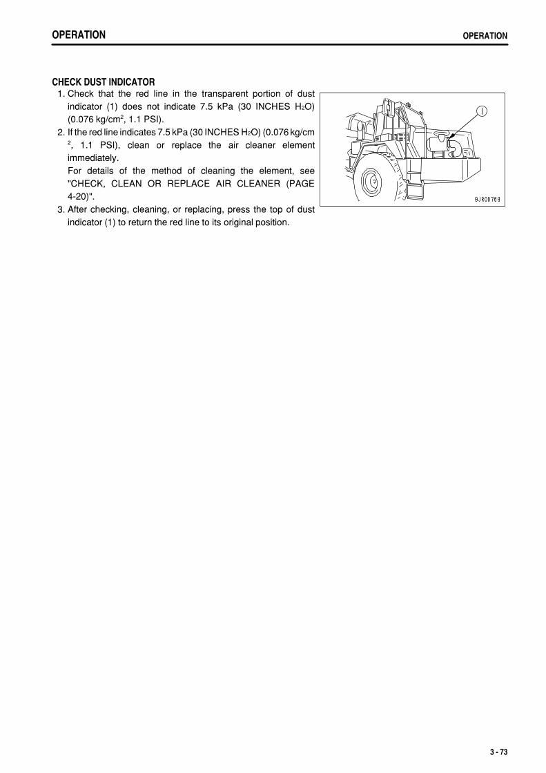
.
OPERATION OPERATION
CHECK DUST INDICATOR 1. Check that the red line in the transparent portion of dust
indicator (1) does not indicate 7.5 kPa (30 INCHES H2O)(0.076 kg/cm2, 1.1 PSI).
2. If the red line indicates 7.5 kPa (30 INCHES H2O) (0.076 kg/cm2, 1.1 PSI), clean or replace the air cleaner elementimmediately.For details of the method of cleaning the element, see"CHECK, CLEAN OR REPLACE AIR CLEANER (PAGE4-20)".
3. After checking, cleaning, or replacing, press the top of dustindicator (1) to return the red line to its original position.
3 - 73
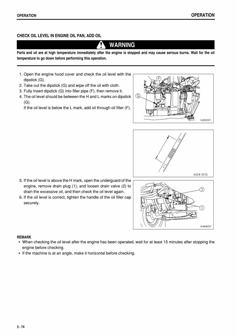
.
OPERATIONOPERATION
CHECK OIL LEVEL IN ENGINE OIL PAN, ADD OIL
WARNINGParts and oil are at high temperature immediately after the engine is stopped and may cause serious burns. Wait for the oiltemperature to go down before performing this operation.
1. Open the engine hood cover and check the oil level with thedipstick (G).
2. Take out the dipstick (G) and wipe off the oil with cloth. 3. Fully insert dipstick (G) into filler pipe (F), then remove it. 4. The oil level should be between the H and L marks on dipstick
(G).If the oil level is below the L mark, add oil through oil filler (F).
5. If the oil level is above the H mark, open the underguard of theengine, remove drain plug (1), and loosen drain valve (2) todrain the excessive oil, and then check the oil level again.
6. If the oil level is correct, tighten the handle of the oil filler capsecurely.
REMARKWhen checking the oil level after the engine has been operated, wait for at least 15 minutes after stopping theengine before checking.If the machine is at an angle, make it horizontal before checking.
3 - 74
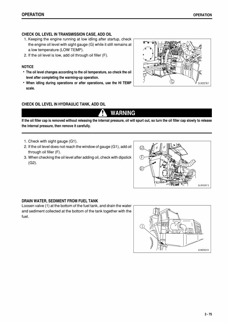
.
OPERATION OPERATION
CHECK OIL LEVEL IN TRANSMISSION CASE, ADD OIL 1. Keeping the engine running at low idling after startup, check
the engine oil level with sight gauge (G) while it still remains ata low temperature (LOW TEMP).
2. If the oil level is low, add oil through oil filler (F).
NOTICEThe oil level changes according to the oil temperature, so check the oillevel after completing the warming-up operation.When idling during operations or after operations, use the HI TEMPscale.
CHECK OIL LEVEL IN HYDRAULIC TANK, ADD OIL
WARNINGIf the oil filler cap is removed without releasing the internal pressure, oil will spurt out, so turn the oil filler cap slowly to releasethe internal pressure, then remove it carefully.
1. Check with sight gauge (G1). 2. If the oil level does not reach the window of gauge (G1), add oil
through oil filler (F). 3. When checking the oil level after adding oil, check with dipstick
(G2).
DRAIN WATER, SEDIMENT FROM FUEL TANKLoosen valve (1) at the bottom of the fuel tank, and drain the waterand sediment collected at the bottom of the tank together with thefuel.
3 - 75
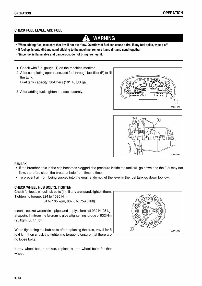
.
OPERATIONOPERATION
CHECK FUEL LEVEL, ADD FUEL
WARNINGWhen adding fuel, take care that it will not overflow. Overflow of fuel can cause a fire. If any fuel spills, wipe it off.If fuel spills onto dirt and sand sticking to the machine, remove it and dirt and sand together.Since fuel is flammable and dangerous, do not bring fire near it.
1. Check with fuel gauge (1) on the machine monitor. 2. After completing operations, add fuel through fuel filler (F) to fill
the tank.Fuel tank capacity: 384 liters (101.45 US gal)
3. After adding fuel, tighten the cap securely.
REMARKIf the breather hole in the cap becomes clogged, the pressure inside the tank will go down and the fuel may notflow, therefore clean the breather hole from time to time.To prevent air from being sucked into the engine, do not let the level in the fuel tank go down too low.
CHECK WHEEL HUB BOLTS, TIGHTENCheck for loose wheel hub bolts (1). If any are found, tighten them.Tightening torque: 824 to 1030 Nm
(84 to 105 kgm, 607.6 to 759.5 lbft)
Insert a socket wrench in a pipe, and apply a force of 932 N (95 kg)at a point 1 m from the fulcrum to give a tightening torque of 932 Nm(95 kgm, 687.1 lbft).
When tightening the hub bolts after replacing the tires, travel for 5to 6 km, then check the tightening torque to ensure that there areno loose bolts.
If any wheel bolt is broken, replace all the wheel bolts for thatwheel.
3 - 76
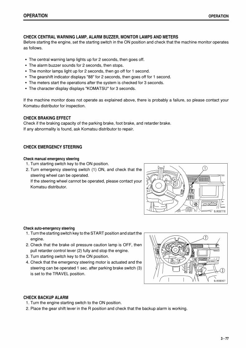
.
OPERATION OPERATION
CHECK CENTRAL WARNING LAMP, ALARM BUZZER, MONITOR LAMPS AND METERSBefore starting the engine, set the starting switch in the ON position and check that the machine monitor operatesas follows.
The central warning lamp lights up for 2 seconds, then goes off.The alarm buzzer sounds for 2 seconds, then stops.The monitor lamps light up for 2 seconds, then go off for 1 second.The gearshift indicator displays "88" for 2 seconds, then goes off for 1 second.The meters start the operations after the system is checked for 3 seconds.The character display displays "KOMATSU" for 3 seconds.
If the machine monitor does not operate as explained above, there is probably a failure, so please contact yourKomatsu distributor for inspection.
CHECK BRAKING EFFECTCheck if the braking capacity of the parking brake, foot brake, and retarder brake.If any abnormality is found, ask Komatsu distributor to repair.
CHECK EMERGENCY STEERING
Check manual emergency steering 1. Turn starting switch key to the ON position. 2. Turn emergency steering switch (1) ON, and check that the
steering wheel can be operated.If the steering wheel cannot be operated, please contact yourKomatsu distributor.
Check auto-emergency steering 1. Turn the starting switch key to the START position and start the
engine. 2. Check that the brake oil pressure caution lamp is OFF, then
pull retarder control lever (2) fully and stop the engine. 3. Turn starting switch key to the ON position. 4. Check that the emergency steering motor is actuated and the
steering can be operated 1 sec. after parking brake switch (3)is set to the TRAVEL position.
CHECK BACKUP ALARM 1. Turn the engine starting switch to the ON position. 2. Place the gear shift lever in the R position and check that the backup alarm is working.
3 - 77
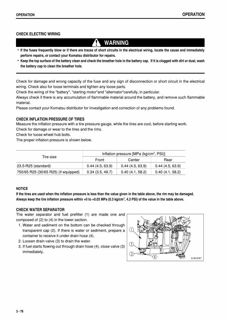
.
OPERATIONOPERATION
CHECK ELECTRIC WIRING
WARNINGIf the fuses frequently blow or if there are traces of short circuits in the electrical wiring, locate the cause and immediatelyperform repairs, or contact your Komatsu distributor for repairs.Keep the top surface of the battery clean and check the breather hole in the battery cap. If it is clogged with dirt or dust, washthe battery cap to clean the breather hole.
Check for damage and wrong capacity of the fuse and any sign of disconnection or short circuit in the electricalwiring. Check also for loose terminals and tighten any loose parts.Check the wiring of the "battery", "starting motor"and "alternator"carefully, in particular.Always check if there is any accumulation of flammable material around the battery, and remove such flammablematerial.Please contact your Komatsu distributor for investigation and correction of any problems found.
CHECK INFLATION PRESSURE OF TIRESMeasure the inflation pressure with a tire pressure gauge, while the tires are cool, before starting work.Check for damage or wear to the tires and the rims.Check for loose wheel hub bolts.The proper inflation pressure is shown below.
Tire sizeInflation pressure [MPa (kg/cm2, PSI)]
Front Center Rear
23.5-R25 (standard) 0.44 (4.5, 63.9) 0.44 (4.5, 63.9) 0.44 (4.5, 63.9)
750/65 R25 (30/65 R25) (if equipped) 0.34 (3.5, 49.7) 0.40 (4.1, 58.2) 0.40 (4.1, 58.2)
NOTICEIf the tires are used when the inflation pressure is less than the value given in the table above, the rim may be damaged.Always keep the tire inflation pressure within +0 to +0.03 MPa (0.3 kg/cm2, 4.3 PSI) of the value in the table above.
CHECK WATER SEPARATORThe water separator and fuel prefilter (1) are made one andcomposed of (2) to (4) in the lower section. 1. Water and sediment on the bottom can be checked through
transparent cap (2). If there is water or sediment, prepare acontainer to receive it under drain hose (4).
2. Loosen drain valve (3) to drain the water. 3. If fuel starts flowing out through drain hose (4), close valve (3)
immediately.
3 - 78
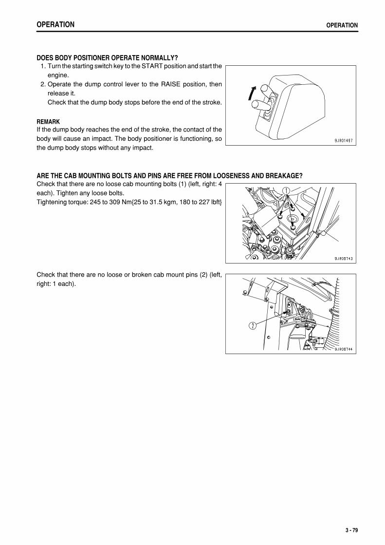
.
OPERATION OPERATION
DOES BODY POSITIONER OPERATE NORMALLY? 1. Turn the starting switch key to the START position and start the
engine. 2. Operate the dump control lever to the RAISE position, then
release it.Check that the dump body stops before the end of the stroke.
REMARKIf the dump body reaches the end of the stroke, the contact of thebody will cause an impact. The body positioner is functioning, sothe dump body stops without any impact.
ARE THE CAB MOUNTING BOLTS AND PINS ARE FREE FROM LOOSENESS AND BREAKAGE?Check that there are no loose cab mounting bolts (1) (left, right: 4each). Tighten any loose bolts.Tightening torque: 245 to 309 Nm{25 to 31.5 kgm, 180 to 227 lbft}
Check that there are no loose or broken cab mount pins (2) (left,right: 1 each).
3 - 79
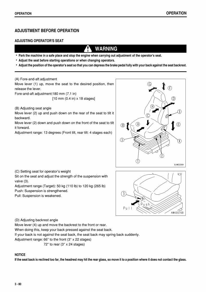
.
OPERATIONOPERATION
ADJUSTMENT BEFORE OPERATION
ADJUSTING OPERATOR'S SEAT
WARNINGPark the machine in a safe place and stop the engine when carrying out adjustment of the operator's seat.Adjust the seat before starting operations or when changing operators.Adjust the position of the operator's seat so that you can depress the brake pedal fully with your back against the seat backrest.
(A) Fore-and-aft adjustmentMove lever (1) up, move the seat to the desired position, thenrelease the lever.Fore-and-aft adjustment:180 mm (7.1 in)
[10 mm (0.4 in) x 18 stages]
(B) Adjusting seat angleMove lever (2) up and push down on the rear of the seat to tilt itbackward.Move lever (2) down and push down on the front of the seat to tiltit forward.Adjustment range: 13 degrees (Front tilt, rear tilt: 4 stages each)
(C) Setting seat for operator's weightSit on the seat and adjust the strength of the suspension withvalve (3).Adjustment range (Target): 50 kg (110 lb) to 120 kg (265 lb)Push: Suspension is strengthened.Pull: Suspension is weakened.
(D) Adjusting backrest angleMove lever (4) up and move the backrest to the front or rear.When doing this, keep your back pressed against the seat back.If your back is not against the seat back, the seat back may spring back suddenly.Adjustment range: 66° to the front (3° x 22 stages)
72° to rear (3° x 24 stages)
NOTICEIf the seat back is reclined too far, the headrest may hit the rear glass, so move it to a position where it does not contact the glass.
3 - 80
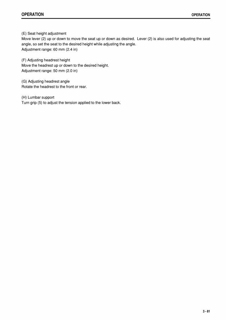
.
OPERATION OPERATION
(E) Seat height adjustmentMove lever (2) up or down to move the seat up or down as desired. Lever (2) is also used for adjusting the seatangle, so set the seat to the desired height while adjusting the angle.Adjustment range: 60 mm (2.4 in)
(F) Adjusting headrest heightMove the headrest up or down to the desired height.Adjustment range: 50 mm (2.0 in)
(G) Adjusting headrest angleRotate the headrest to the front or rear.
(H) Lumbar supportTurn grip (5) to adjust the tension applied to the lower back.
3 - 81
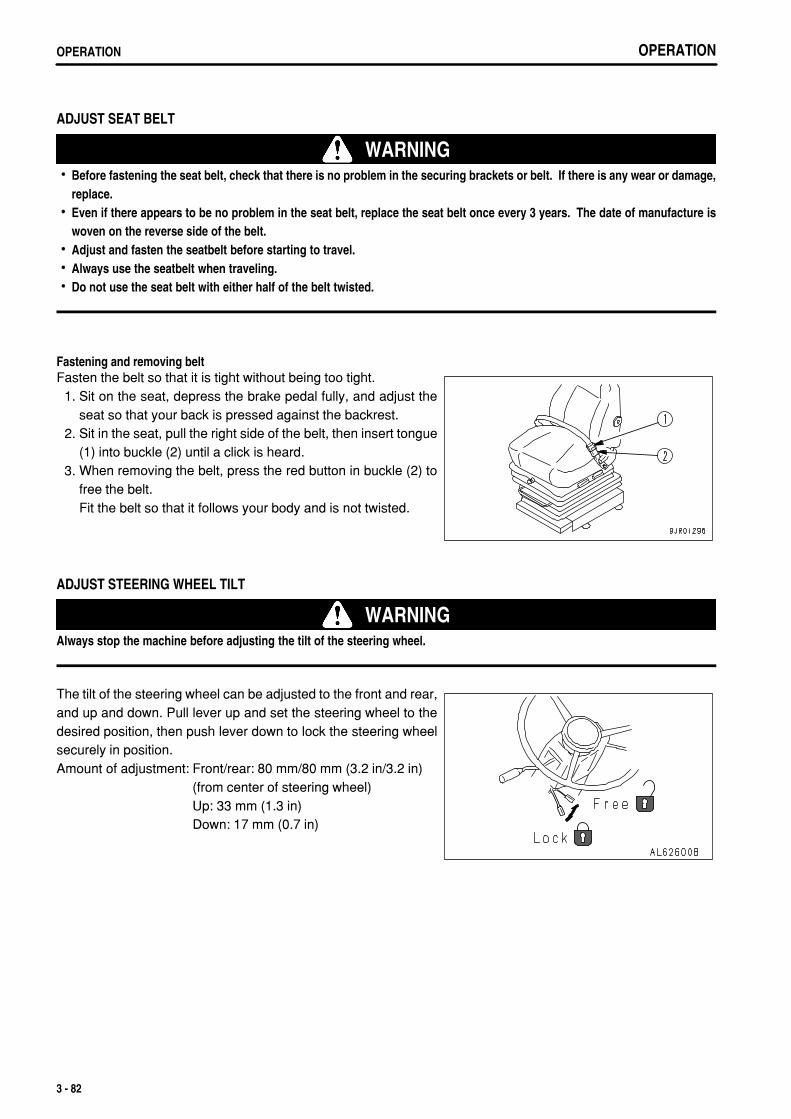
.
OPERATIONOPERATION
ADJUST SEAT BELT
WARNINGBefore fastening the seat belt, check that there is no problem in the securing brackets or belt. If there is any wear or damage,replace.Even if there appears to be no problem in the seat belt, replace the seat belt once every 3 years. The date of manufacture iswoven on the reverse side of the belt.Adjust and fasten the seatbelt before starting to travel.Always use the seatbelt when traveling.Do not use the seat belt with either half of the belt twisted.
Fastening and removing beltFasten the belt so that it is tight without being too tight. 1. Sit on the seat, depress the brake pedal fully, and adjust the
seat so that your back is pressed against the backrest. 2. Sit in the seat, pull the right side of the belt, then insert tongue
(1) into buckle (2) until a click is heard. 3. When removing the belt, press the red button in buckle (2) to
free the belt.Fit the belt so that it follows your body and is not twisted.
ADJUST STEERING WHEEL TILT
WARNINGAlways stop the machine before adjusting the tilt of the steering wheel.
The tilt of the steering wheel can be adjusted to the front and rear,and up and down. Pull lever up and set the steering wheel to thedesired position, then push lever down to lock the steering wheelsecurely in position.Amount of adjustment: Front/rear: 80 mm/80 mm (3.2 in/3.2 in)
(from center of steering wheel)Up: 33 mm (1.3 in)Down: 17 mm (0.7 in)
3 - 82
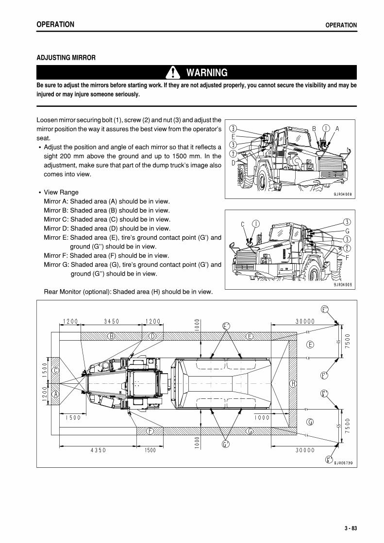
.
OPERATION OPERATION
ADJUSTING MIRROR
WARNINGBe sure to adjust the mirrors before starting work. If they are not adjusted properly, you cannot secure the visibility and may beinjured or may injure someone seriously.
Loosen mirror securing bolt (1), screw (2) and nut (3) and adjust themirror position the way it assures the best view from the operator'sseat.
Adjust the position and angle of each mirror so that it reflects asight 200 mm above the ground and up to 1500 mm. In theadjustment, make sure that part of the dump truck's image alsocomes into view.
View RangeMirror A: Shaded area (A) should be in view.Mirror B: Shaded area (B) should be in view.Mirror C: Shaded area (C) should be in view.Mirror D: Shaded area (D) should be in view.Mirror E: Shaded area (E), tire's ground contact point (G') and
ground (G'') should be in view.Mirror F: Shaded area (F) should be in view.Mirror G: Shaded area (G), tire's ground contact point (G') and
ground (G'') should be in view.
Rear Monitor (optional): Shaded area (H) should be in view.
3 - 83
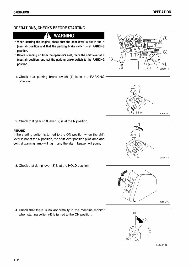
.
OPERATIONOPERATION
OPERATIONS, CHECKS BEFORE STARTING
WARNINGWhen starting the engine, check that the shift lever is set in the N(neutral) position and that the parking brake switch is at PARKINGposition.Before standing up from the operator's seat, place the shift lever at N(neutral) position, and set the parking brake switch to the PARKINGposition.
1. Check that parking brake switch (1) is in the PARKINGposition.
2. Check that gear shift lever (2) is at the N position.
REMARKIf the starting switch is turned to the ON position when the shiftlever is not at the N position, the shift lever position pilot lamp andcentral warning lamp will flash, and the alarm buzzer will sound.
3. Check that dump lever (3) is at the HOLD position.
4. Check that there is no abnormality in the machine monitorwhen starting switch (4) is turned to the ON position.
3 - 84
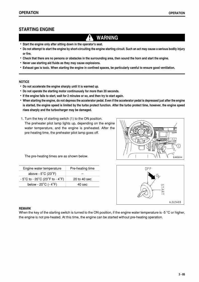
.
OPERATION OPERATION
STARTING ENGINE
WARNINGStart the engine only after sitting down in the operator's seat.Do not attempt to start the engine by short-circuiting the engine starting circuit. Such an act may cause a serious bodily injuryor fire.Check that there are no persons or obstacles in the surrounding area, then sound the horn and start the engine.Never use starting aid fluids as they may cause explosions.Exhaust gas is toxic. When starting the engine in confined spaces, be particularly careful to ensure good ventilation.
NOTICEDo not accelerate the engine sharply until it is warmed up.Do not operate the starting motor continuously for more than 20 seconds.If the engine fails to start, wait for 2 minutes or so, and then try to start again.When starting the engine, do not depress the accelerator pedal. Even if the accelerator pedal is depressed just after the engineis started, the engine speed is limited by the turbo protect function. After the turbo protect time, however, the engine speedrises sharply and the turbocharger may be damaged.
1. Turn the key of starting switch (1) to the ON position.The preheater pilot lamp lights up, depending on the enginewater temperature, and the engine is preheated. After thepre-heating time, the preheater pilot lamp goes off.
The pre-heating times are as shown below.
Engine water temperature Pre-heating time
above - 5°C (23°F) –
- 5°C to - 20°C (23°F to - 4°F) 20 to 40 sec
below - 20°C (- 4°F) 40 sec
REMARKWhen the key of the starting switch is turned to the ON position, if the engine water temperature is -5 °C or higher,the engine is not pre-heated. At this time, the engine can be started without pre-heating operation.
3 - 85
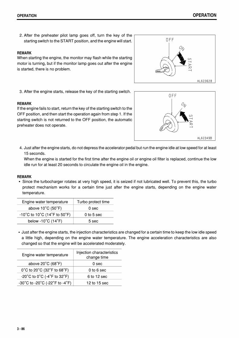
.
OPERATIONOPERATION OPERATIONOPERATION
2. After the preheater pilot lamp goes off, turn the key of thestarting switch to the START position, and the engine will start.
REMARKWhen starting the engine, the monitor may flash while the startingmotor is turning, but if the monitor lamp goes out after the engineis started, there is no problem.
3. After the engine starts, release the key of the starting switch.
REMARKIf the engine fails to start, return the key of the starting switch to theOFF position, and then start the operation again from step 1. If thestarting switch is not returned to the OFF position, the automaticpreheater does not operate.
4. Just after the engine starts, do not depress the accelerator pedal but run the engine idle at low speed for at least15 seconds.When the engine is started for the first time after the engine oil or engine oil filter is replaced, continue the lowidle run for at least 20 seconds to circulate the engine oil in the engine.
REMARKSince the turbocharger rotates at very high speed, it is seized if not lubricated well. To prevent this, the turboprotect mechanism works for a certain time just after the engine starts, depending on the engine watertemperature.
Engine water temperature Turbo protect time
above 10°C (50°F) 0 sec
-10°C to 10°C (14°F to 50°F) 0 to 5 sec
below -10°C (14°F) 5 sec
Just after the engine starts, the injection characteristics are changed for a certain time to keep the low idle speeda little high, depending on the engine water temperature. The engine acceleration characteristics are alsochanged so that the engine will be accelerated moderately.
Engine water temperatureInjection characteristics
change time
above 20°C (68°F) 0 sec
0°C to 20°C (32°F to 68°F) 0 to 6 sec
-20°C to 0°C (-4°F to 32°F) 6 to 12 sec
-30°C to -20°C (-22°F to -4°F) 12 to 15 sec
3 - 86
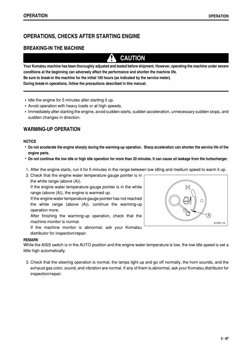
.
OPERATION OPERATION
OPERATIONS, CHECKS AFTER STARTING ENGINE
BREAKING-IN THE MACHINE
CAUTIONYour Komatsu machine has been thoroughly adjusted and tested before shipment. However, operating the machine under severeconditions at the beginning can adversely affect the performance and shorten the machine life.Be sure to break-in the machine for the initial 100 hours (as indicated by the service meter).During break-in operations, follow the precautions described in this manual.
Idle the engine for 5 minutes after starting it up.Avoid operation with heavy loads or at high speeds.Immediately after starting the engine, avoid sudden starts, sudden acceleration, unnecessary sudden stops, andsudden changes in direction.
WARMING-UP OPERATION
NOTICEDo not accelerate the engine sharply during the warming-up operation. Sharp acceleration can shorten the service life of theengine parts.Do not continue the low idle or high idle operation for more than 20 minutes. It can cause oil leakage from the turbocharger.
1. After the engine starts, run it for 5 minutes in the range between low idling and medium speed to warm it up. 2. Check that the engine water temperature gauge pointer is in
the white range (above (A)).If the engine water temperature gauge pointer is in the whiterange (above (A)), the engine is warmed up.If the engine water temperature gauge pointer has not reachedthe white range (above (A)), continue the warming-upoperation more.After finishing the warming-up operation, check that themachine monitor is normal.If the machine monitor is abnormal, ask your Komatsudistributor for inspection/repair.
REMARKWhile the AISS switch is in the AUTO position and the engine water temperature is low, the low idle speed is set alittle high automatically.
3. Check that the steering operation is normal, the lamps light up and go off normally, the horn sounds, and theexhaust gas color, sound, and vibration are normal. If any of them is abnormal, ask your Komatsu distributor forinspection/repair.
3 - 87
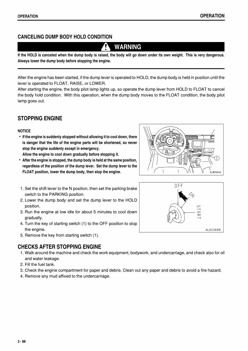
.
OPERATIONOPERATION
CANCELING DUMP BODY HOLD CONDITION
WARNINGIf the HOLD is canceled when the dump body is raised, the body will go down under its own weight. This is very dangerous.Always lower the dump body before stopping the engine.
After the engine has been started, if the dump lever is operated to HOLD, the dump body is held in position until thelever is operated to FLOAT, RAISE, or LOWER.After starting the engine, the body pilot lamp lights up, so operate the dump lever from HOLD to FLOAT to cancelthe body hold condition. With this operation, when the dump body moves to the FLOAT condition, the body pilotlamp goes out.
STOPPING ENGINE
NOTICEIf the engine is suddenly stopped without allowing it to cool down, thereis danger that the life of the engine parts will be shortened, so neverstop the engine suddenly except in emergency.Allow the engine to cool down gradually before stopping it.After the engine is stopped, the dump body is held at the same position,regardless of the position of the dump lever. Set the dump lever to theFLOAT position, lower the dump body, then stop the engine.
1. Set the shift lever to the N position, then set the parking brakeswitch to the PARKING position.
2. Lower the dump body and set the dump lever to the HOLDposition.
3. Run the engine at low idle for about 5 minutes to cool downgradually.
4. Turn the key of starting switch (1) to the OFF position to stopthe engine.
5. Remove the key from starting switch (1).
CHECKS AFTER STOPPING ENGINE 1. Walk around the machine and check the work equipment, bodywork, and undercarriage, and check also for oil
and water leakage. 2. Fill the fuel tank. 3. Check the engine compartment for paper and debris. Clean out any paper and debris to avoid a fire hazard. 4. Remove any mud affixed to the undercarriage.
3 - 88
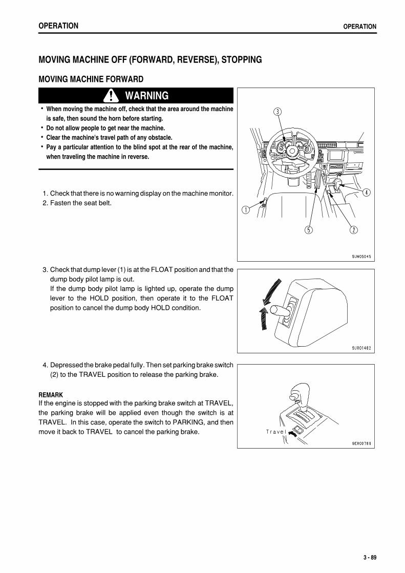
.
OPERATION OPERATION
MOVING MACHINE OFF (FORWARD, REVERSE), STOPPING
MOVING MACHINE FORWARD
WARNINGWhen moving the machine off, check that the area around the machineis safe, then sound the horn before starting.Do not allow people to get near the machine.Clear the machine's travel path of any obstacle.Pay a particular attention to the blind spot at the rear of the machine,when traveling the machine in reverse.
1. Check that there is no warning display on the machine monitor. 2. Fasten the seat belt.
3. Check that dump lever (1) is at the FLOAT position and that thedump body pilot lamp is out. If the dump body pilot lamp is lighted up, operate the dumplever to the HOLD position, then operate it to the FLOATposition to cancel the dump body HOLD condition.
4. Depressed the brake pedal fully. Then set parking brake switch(2) to the TRAVEL position to release the parking brake.
REMARKIf the engine is stopped with the parking brake switch at TRAVEL,the parking brake will be applied even though the switch is atTRAVEL. In this case, operate the switch to PARKING, and thenmove it back to TRAVEL to cancel the parking brake.
3 - 89
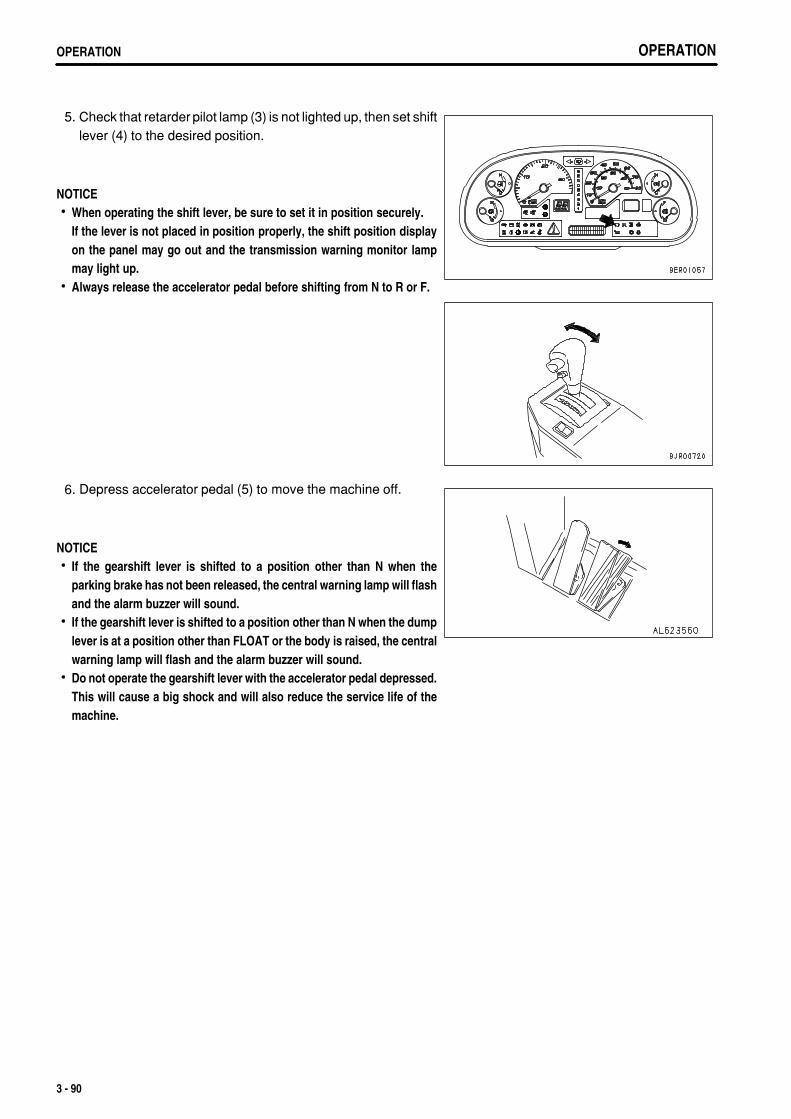
.
OPERATIONOPERATION OPERATIONOPERATION
5. Check that retarder pilot lamp (3) is not lighted up, then set shiftlever (4) to the desired position.
NOTICEWhen operating the shift lever, be sure to set it in position securely.If the lever is not placed in position properly, the shift position displayon the panel may go out and the transmission warning monitor lampmay light up.Always release the accelerator pedal before shifting from N to R or F.
6. Depress accelerator pedal (5) to move the machine off.
NOTICEIf the gearshift lever is shifted to a position other than N when theparking brake has not been released, the central warning lamp will flashand the alarm buzzer will sound.If the gearshift lever is shifted to a position other than N when the dumplever is at a position other than FLOAT or the body is raised, the centralwarning lamp will flash and the alarm buzzer will sound.Do not operate the gearshift lever with the accelerator pedal depressed.This will cause a big shock and will also reduce the service life of themachine.
3 - 90
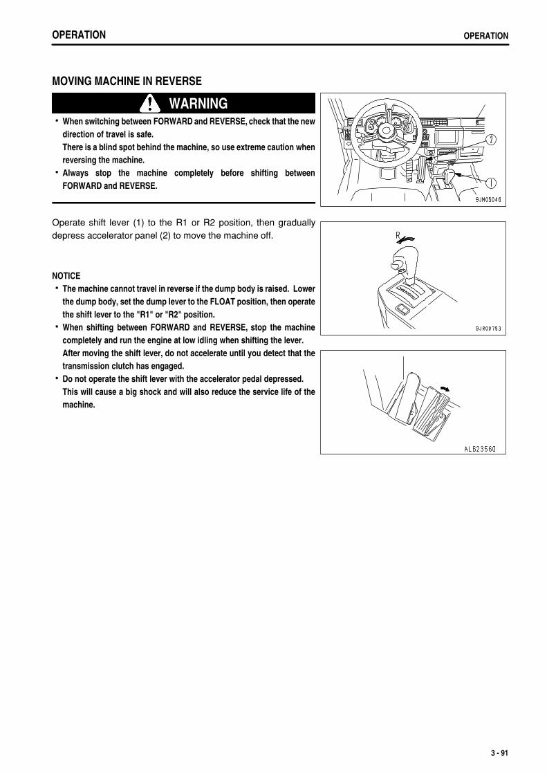
.
OPERATION OPERATION
MOVING MACHINE IN REVERSE
WARNINGWhen switching between FORWARD and REVERSE, check that the newdirection of travel is safe.There is a blind spot behind the machine, so use extreme caution whenreversing the machine.Always stop the machine completely before shifting betweenFORWARD and REVERSE.
Operate shift lever (1) to the R1 or R2 position, then graduallydepress accelerator panel (2) to move the machine off.
NOTICEThe machine cannot travel in reverse if the dump body is raised. Lowerthe dump body, set the dump lever to the FLOAT position, then operatethe shift lever to the "R1" or "R2" position.When shifting between FORWARD and REVERSE, stop the machinecompletely and run the engine at low idling when shifting the lever.After moving the shift lever, do not accelerate until you detect that thetransmission clutch has engaged.Do not operate the shift lever with the accelerator pedal depressed.This will cause a big shock and will also reduce the service life of themachine.
3 - 91
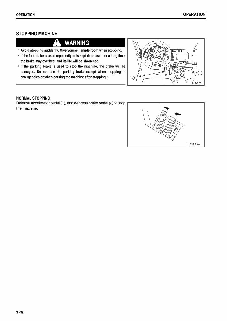
.
OPERATIONOPERATION
STOPPING MACHINE
WARNINGAvoid stopping suddenly. Give yourself ample room when stopping.If the foot brake is used repeatedly or is kept depressed for a long time,the brake may overheat and its life will be shortened.If the parking brake is used to stop the machine, the brake will bedamaged. Do not use the parking brake except when stopping inemergencies or when parking the machine after stopping it.
NORMAL STOPPINGRelease accelerator pedal (1), and depress brake pedal (2) to stopthe machine.
3 - 92
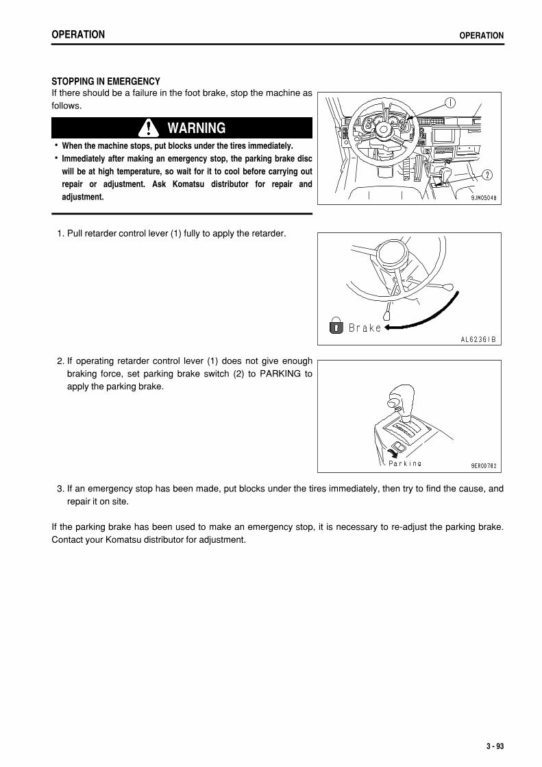
.
OPERATION OPERATION
STOPPING IN EMERGENCYIf there should be a failure in the foot brake, stop the machine asfollows.
WARNINGWhen the machine stops, put blocks under the tires immediately.Immediately after making an emergency stop, the parking brake discwill be at high temperature, so wait for it to cool before carrying outrepair or adjustment. Ask Komatsu distributor for repair andadjustment.
1. Pull retarder control lever (1) fully to apply the retarder.
2. If operating retarder control lever (1) does not give enoughbraking force, set parking brake switch (2) to PARKING toapply the parking brake.
3. If an emergency stop has been made, put blocks under the tires immediately, then try to find the cause, andrepair it on site.
If the parking brake has been used to make an emergency stop, it is necessary to re-adjust the parking brake.Contact your Komatsu distributor for adjustment.
3 - 93
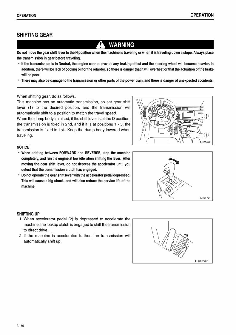
.
OPERATIONOPERATION
SHIFTING GEAR
WARNINGDo not move the gear shift lever to the N position when the machine is traveling or when it is traveling down a slope. Always placethe transmission in gear before traveling.
If the transmission is in Neutral, the engine cannot provide any braking effect and the steering wheel will become heavier. Inaddition, there will be lack of cooling oil for the retarder, so there is danger that it will overheat or that the actuation of the brakewill be poor.There may also be damage to the transmission or other parts of the power train, and there is danger of unexpected accidents.
When shifting gear, do as follows.This machine has an automatic transmission, so set gear shiftlever (1) to the desired position, and the transmission willautomatically shift to a position to match the travel speed.When the dump body is raised, if the shift lever is at the D position,the transmission is fixed in 2nd, and if it is at positions 1 - 5, thetransmission is fixed in 1st. Keep the dump body lowered whentraveling.
NOTICEWhen shifting between FORWARD and REVERSE, stop the machinecompletely, and run the engine at low idle when shifting the lever. Aftermoving the gear shift lever, do not depress the accelerator until youdetect that the transmission clutch has engaged.Do not operate the gear shift lever with the accelerator pedal depressed.This will cause a big shock, and will also reduce the service life of themachine.
SHIFTING UP 1. When accelerator pedal (2) is depressed to accelerate the
machine, the lockup clutch is engaged to shift the transmissionto direct drive.
2. If the machine is accelerated further, the transmission willautomatically shift up.
3 - 94
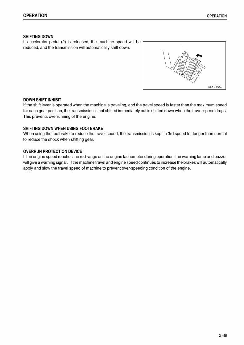
.
OPERATION OPERATION
SHIFTING DOWNIf accelerator pedal (2) is released, the machine speed will bereduced, and the transmission will automatically shift down.
DOWN SHIFT INHIBITIf the shift lever is operated when the machine is traveling, and the travel speed is faster than the maximum speedfor each gear position, the transmission is not shifted immediately but is shifted down when the travel speed drops.This prevents overrunning of the engine.
SHIFTING DOWN WHEN USING FOOTBRAKEWhen using the footbrake to reduce the travel speed, the transmission is kept in 3rd speed for longer than normalto reduce the shock when shifting gear.
OVERRUN PROTECTION DEVICEIf the engine speed reaches the red range on the engine tachometer during operation, the warning lamp and buzzerwill give a warning signal. If the machine travel and engine speed continues to increase the brakes will automaticallyapply and slow the travel speed of machine to prevent over-speeding condition of the engine.
3 - 95
.
OPERATIONOPERATION
TRAVELING DOWNHILLWhen traveling downhill, travel at a safe speed which matches the width of the road, the condition of the roadsurface, and other conditions of the jobsite.
WARNINGWhen the machine stops, put blocks under the tires immediately.For the maximum permissible speed when traveling downhill using the retarder, see the brake performance graph for thedownhill distance and grade. Traveling continuously downhill at a speed greater than the maximum permitted speed on thebrake performance graph is dangerous as the retarder brake may be damaged.If the retarder oil temperature caution lamp on the machine monitor lights up when the retarder is being used, shift down totravel downhill. (When this happens, the central warning lamp lights up and the alarm buzzer sounds.)If the caution lamp does not go out even when the transmission is shifted down, stop the machine immediately, set the shiftlever to the N position, run the engine at 1800 rpm, and wait for the caution lamp to go out.If the retarder loses its effect when it is used for traveling downhill, do as follows.
1. Release the retarder control lever completely, then operate the retarder control lever again. 2. If the retarder still has no effect even when the retarder control lever is operated again, return the retarder control lever
completely to the released position, then depress the brake pedal to stop the machine, and contact your Komatsu distributorfor repairs.
Operate the retarder slowly. If the brake is applied suddenly, there is danger that the tires will slip.Do not move the gear shift lever to the N position when the machine is traveling or when it is traveling down a slope. Alwaysplace the transmission in gear before traveling.o If the transmission is in Neutral, the engine cannot provide any braking effect and the steering wheel will become heavier.In addition, there will be lack of cooling oil for the retarder, so there is danger that it will overheat or that the actuation of thebrake will be poor.o There may also be damage to the transmission or other parts of the power train, and there is danger of unexpected accidents.
NOTICEIf the retarder control lever is operated when traveling downhill, the transmission can be shifted down sooner than with normaldeceleration. It is also possible to travel without shifting up.Do not accelerate or shift up when using the retarder. The engine speed will rise and this may cause the alarm buzzer to soundand the central warning lamp to flash.
3 - 96
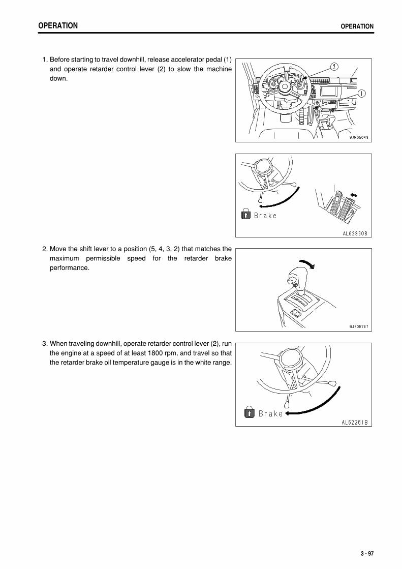
.
OPERATION OPERATIONOPERATION OPERATION
1. Before starting to travel downhill, release accelerator pedal (1)and operate retarder control lever (2) to slow the machinedown.
2. Move the shift lever to a position (5, 4, 3, 2) that matches themaximum permissible speed for the retarder brakeperformance.
3. When traveling downhill, operate retarder control lever (2), runthe engine at a speed of at least 1800 rpm, and travel so thatthe retarder brake oil temperature gauge is in the white range.
3 - 97
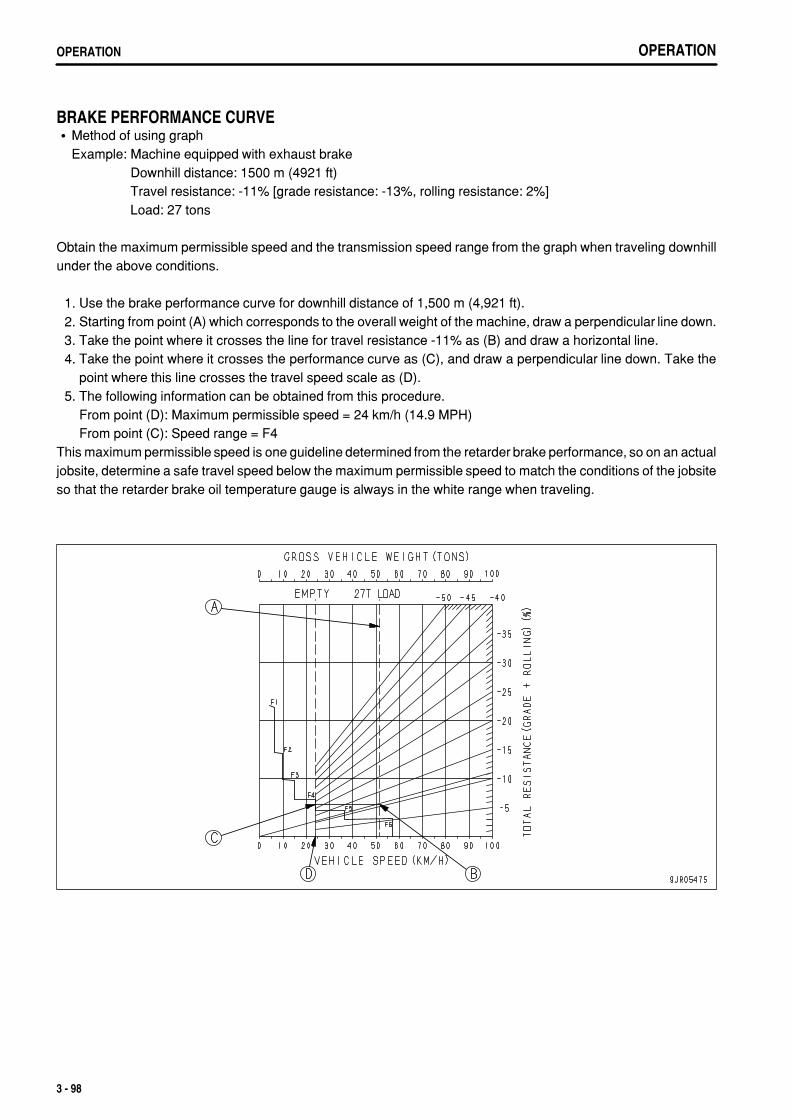
.
OPERATIONOPERATION
BRAKE PERFORMANCE CURVEMethod of using graphExample: Machine equipped with exhaust brake
Downhill distance: 1500 m (4921 ft)Travel resistance: -11% [grade resistance: -13%, rolling resistance: 2%]Load: 27 tons
Obtain the maximum permissible speed and the transmission speed range from the graph when traveling downhillunder the above conditions.
1. Use the brake performance curve for downhill distance of 1,500 m (4,921 ft). 2. Starting from point (A) which corresponds to the overall weight of the machine, draw a perpendicular line down. 3. Take the point where it crosses the line for travel resistance -11% as (B) and draw a horizontal line. 4. Take the point where it crosses the performance curve as (C), and draw a perpendicular line down. Take the
point where this line crosses the travel speed scale as (D). 5. The following information can be obtained from this procedure.
From point (D): Maximum permissible speed = 24 km/h (14.9 MPH)From point (C): Speed range = F4
This maximum permissible speed is one guideline determined from the retarder brake performance, so on an actualjobsite, determine a safe travel speed below the maximum permissible speed to match the conditions of the jobsiteso that the retarder brake oil temperature gauge is always in the white range when traveling.
3 - 98
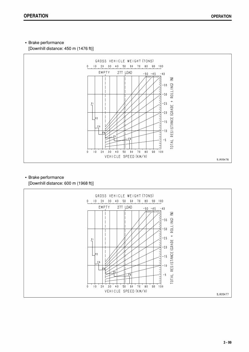
.
OPERATION OPERATION
Brake performance[Downhill distance: 450 m (1476 ft)]
Brake performance[Downhill distance: 600 m (1968 ft)]
3 - 99
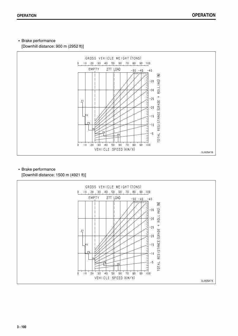
.
OPERATIONOPERATION
Brake performance[Downhill distance: 900 m (2952 ft)]
Brake performance[Downhill distance: 1500 m (4921 ft)]
3 - 100
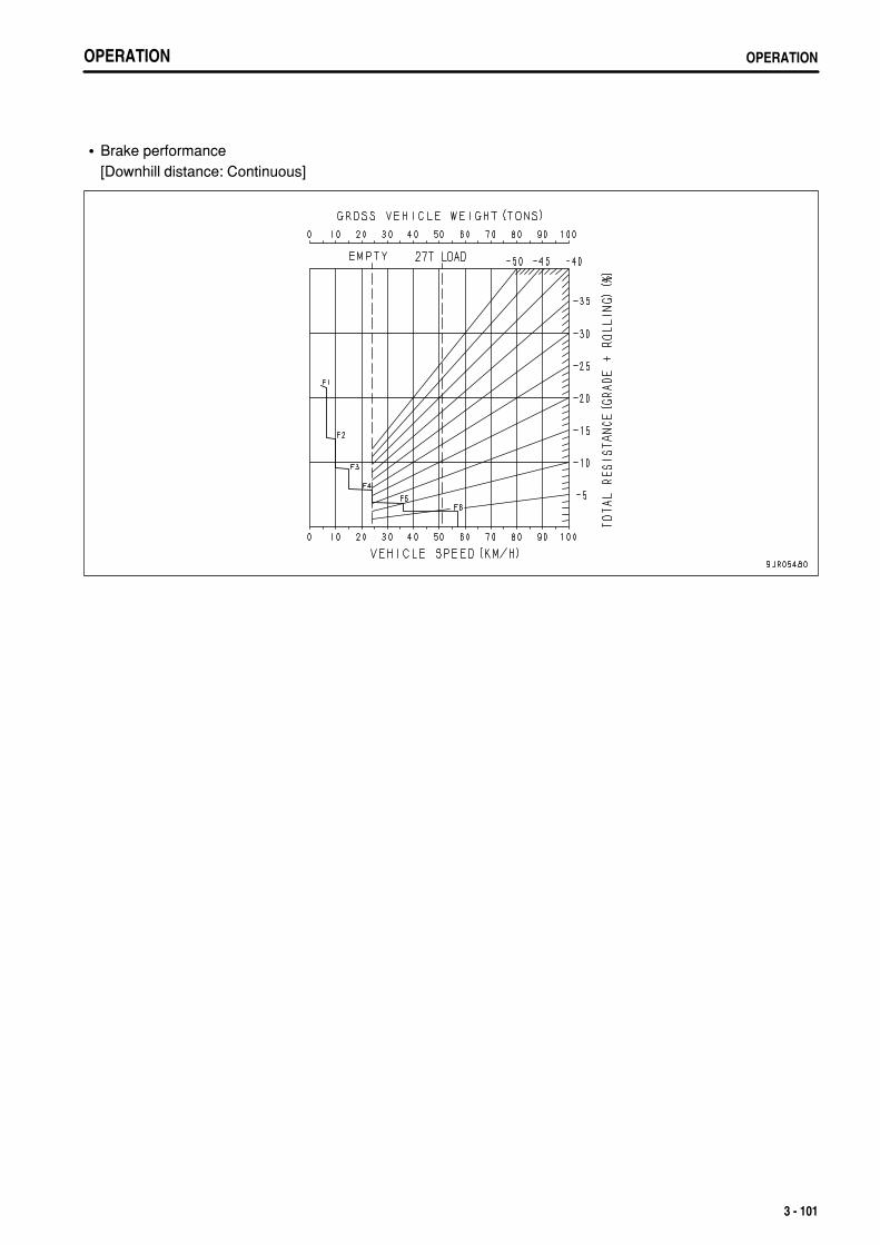
.
OPERATION OPERATION
Brake performance[Downhill distance: Continuous]
3 - 101
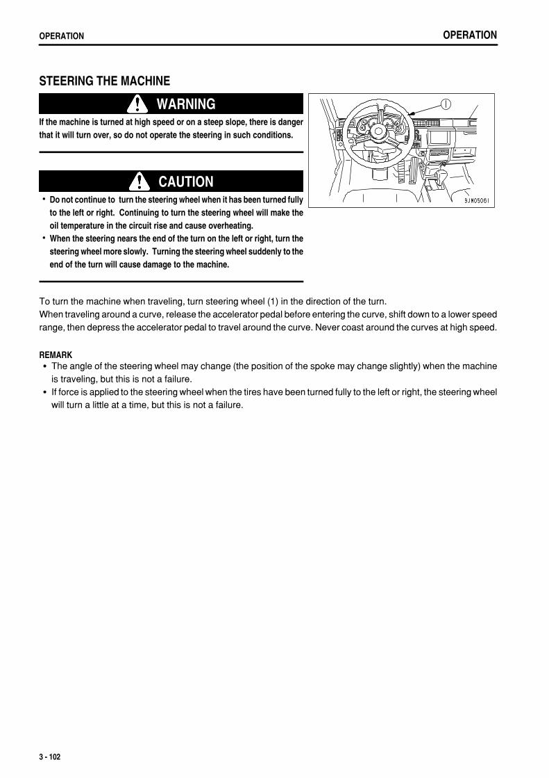
.
OPERATIONOPERATION
STEERING THE MACHINE
WARNINGIf the machine is turned at high speed or on a steep slope, there is dangerthat it will turn over, so do not operate the steering in such conditions.
CAUTIONDo not continue to turn the steering wheel when it has been turned fullyto the left or right. Continuing to turn the steering wheel will make theoil temperature in the circuit rise and cause overheating.When the steering nears the end of the turn on the left or right, turn thesteering wheel more slowly. Turning the steering wheel suddenly to theend of the turn will cause damage to the machine.
To turn the machine when traveling, turn steering wheel (1) in the direction of the turn.When traveling around a curve, release the accelerator pedal before entering the curve, shift down to a lower speedrange, then depress the accelerator pedal to travel around the curve. Never coast around the curves at high speed.
REMARKThe angle of the steering wheel may change (the position of the spoke may change slightly) when the machineis traveling, but this is not a failure.If force is applied to the steering wheel when the tires have been turned fully to the left or right, the steering wheelwill turn a little at a time, but this is not a failure.
3 - 102
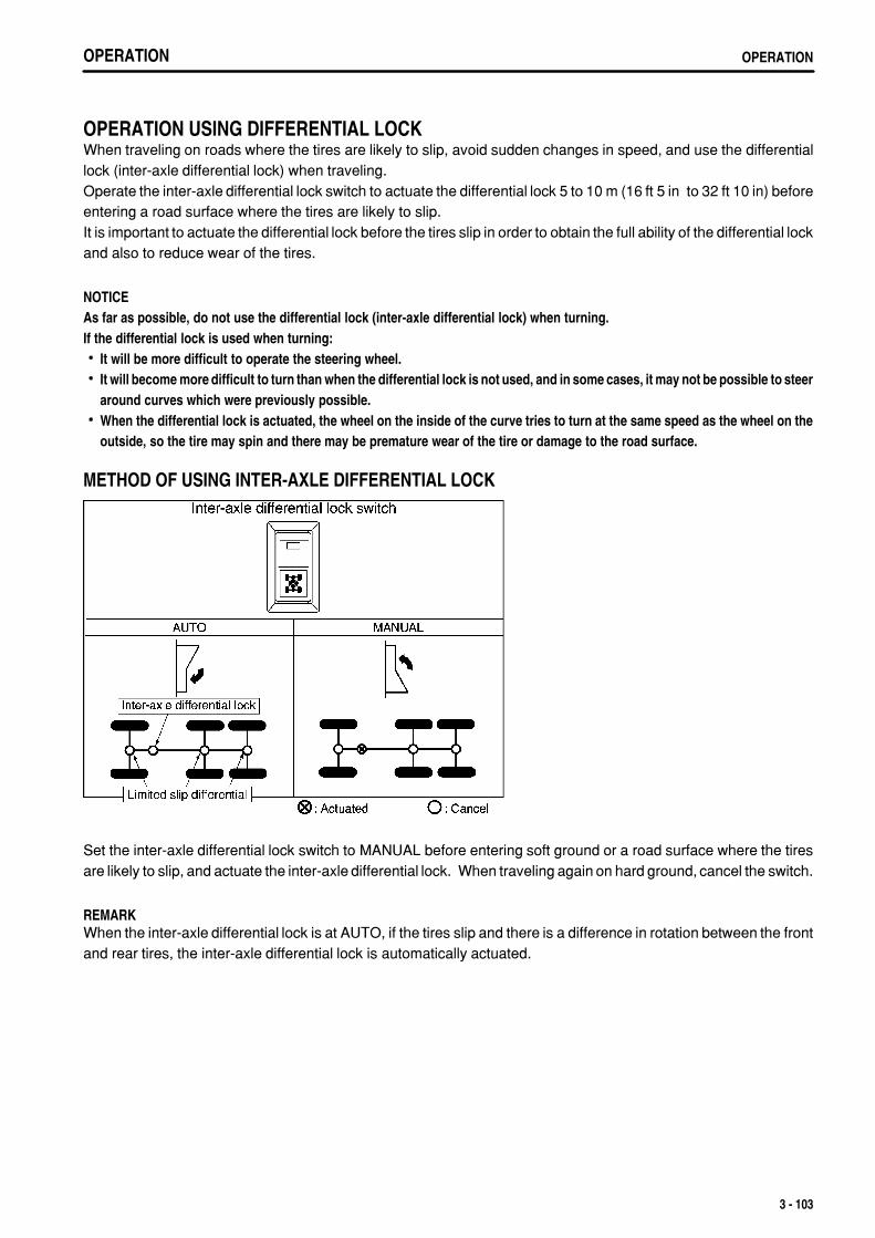
.
OPERATION OPERATION
OPERATION USING DIFFERENTIAL LOCKWhen traveling on roads where the tires are likely to slip, avoid sudden changes in speed, and use the differentiallock (inter-axle differential lock) when traveling.Operate the inter-axle differential lock switch to actuate the differential lock 5 to 10 m (16 ft 5 in to 32 ft 10 in) beforeentering a road surface where the tires are likely to slip.It is important to actuate the differential lock before the tires slip in order to obtain the full ability of the differential lockand also to reduce wear of the tires.
NOTICEAs far as possible, do not use the differential lock (inter-axle differential lock) when turning.If the differential lock is used when turning:
It will be more difficult to operate the steering wheel.It will become more difficult to turn than when the differential lock is not used, and in some cases, it may not be possible to steeraround curves which were previously possible.When the differential lock is actuated, the wheel on the inside of the curve tries to turn at the same speed as the wheel on theoutside, so the tire may spin and there may be premature wear of the tire or damage to the road surface.
METHOD OF USING INTER-AXLE DIFFERENTIAL LOCK
Set the inter-axle differential lock switch to MANUAL before entering soft ground or a road surface where the tiresare likely to slip, and actuate the inter-axle differential lock. When traveling again on hard ground, cancel the switch.
REMARKWhen the inter-axle differential lock is at AUTO, if the tires slip and there is a difference in rotation between the frontand rear tires, the inter-axle differential lock is automatically actuated.
3 - 103
.
OPERATIONOPERATION
WHEN TIRES ARE STUCK IN GROUNDIf the wheels get stuck, to stop the wheels from spinning, do as follows.If it is impossible to get the machine out even when repeating the procedure below, use a bulldozer to tow themachine out.
1. Release the accelerator pedal to stop the wheels from spinning. 2. Actuate the inter-axle differential lock. 3. Set the shift lever to position "5" and raise the engine speed. 4. Release the accelerator pedal and brake pedal. 5. Set the shift lever to position R1 and raise the engine speed. 6. Repeat Steps 1 - 5 to move the machine backwards and forwards until it can escape.
LOADING OPERATIONSWhen using a large wheel loader to load large rocks, if the rocks are loaded directly into the dump body parts of thedump body may be deformed. To prevent this, when loading large rocks, first load sand or soil to act as a cushion,then load the rocks on top of this to reduce the impact on the dump body.In addition, when loading rocks that exceed the following conditions, install the optional dump body reinforcementplate.
Rocks with one side over 0.3 m (11.8 in)Rocks of hardness more than 4.5 (Mohs scale)Rocks with a weight of more than 150 kg (331 lb)When transporting steel ingots
NOTICEWhen traveling, always set the dump lever to the FLOAT position regardless of whether the dump body is empty or loaded.If the dump lever is not at the FLOAT position and the shift lever is not at the N position, the central warning lamp will flush andthe alarm buzzer will sound.
3 - 104

.
OPERATION OPERATION
DUMP OPERATIONS
WARNINGWhen dumping a load, always carry out the dumping operation inaccordance with the signals from the flagman.When dumping large rocks, operate the dump body slowly.Do not load the dump body while it is still raised.When carrying out inspection with the dump body raised, always usethe body pivot pins, set the dump lever to the HOLD position and lockit securely. For details, see "BODY PIVOT PIN (PAGE 3-45)".
Operate the dump body as follows. 1. Place shift lever (1) at the N position, and set parking brake
switch (2) to the PARKING position.
2. Move dump lever (3) to the RAISE position, then depress theaccelerator pedal to raise the dump body.If the dump lever is released when it is at the RAISE position,it is held at the RAISE position and the dump body will continueto rise.The dumping speed increases in proportion to the enginespeed.
3. When the dump body rises to the previously set position, dumplever (3) returns to the HOLD position. The dump body is heldat that position.If it is necessary to raise the dump body further, operate dumplever (3) to the RAISE position and the dump body will rise. Ifdump lever (3) is released, dump lever (3) will return to theHOLD position and the dump body will stop at that position.
3 - 105
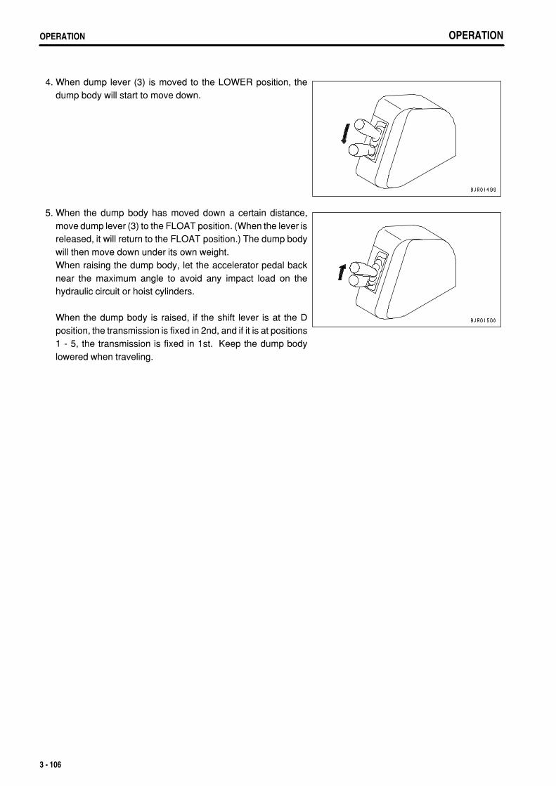
.
OPERATIONOPERATION OPERATIONOPERATION
4. When dump lever (3) is moved to the LOWER position, thedump body will start to move down.
5. When the dump body has moved down a certain distance,move dump lever (3) to the FLOAT position. (When the lever isreleased, it will return to the FLOAT position.) The dump bodywill then move down under its own weight.When raising the dump body, let the accelerator pedal backnear the maximum angle to avoid any impact load on thehydraulic circuit or hoist cylinders.
When the dump body is raised, if the shift lever is at the Dposition, the transmission is fixed in 2nd, and if it is at positions1 - 5, the transmission is fixed in 1st. Keep the dump bodylowered when traveling.
3 - 106
.
OPERATION OPERATION
CAB TILT OPERATION
WARNINGTo prevent serious injury or death if the cab comes down, always observe the following strictly when tilting the cab.Precautions before performing cab tilt operation
Perform the cab tilt operation on a flat place.To prevent interference between the cab and machine body when performing the tilt operation, set the machine facing directlyto the front and secure the front and rear frames with the articulation lock.Set the parking brake switch to the "PARKING" position to apply the parking brake.Lock the dump control lever with the dump lever lock knob.Put blocks under the tires to prevent the machine from moving.Do not perform the cab tilt operation in the strong wind.
Precautions when performing cab tilt operationDo not operate the cab tilt when the machine is loaded.Do not stand under the cab during the cab tilt operation.While the cab is tilted up, fix it with the lock bar securely.While the cab is tilted up, do not ride on or get off it.While the cab is tilted up, do not operate the gear shift lever or dump control lever.Do not start the engine while the cab is tilted up. If it is necessary to start the engine when carrying out inspection, check firstthat there is no one under the cab.Do not subject to the machine to any large impact force while the cab is tilted up.When lowering the cab by using the tilt cylinder, do not lower the hydraulic pressure at a time but lower it gradually to adjustthe lowering speed of the cab.The lock bar is set on the left inside of the engine hood. After using it, be sure to return it.
3 - 107
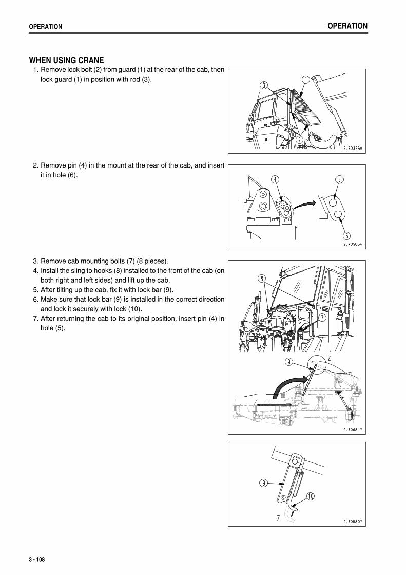
.
OPERATIONOPERATION
WHEN USING CRANE 1. Remove lock bolt (2) from guard (1) at the rear of the cab, then
lock guard (1) in position with rod (3).
2. Remove pin (4) in the mount at the rear of the cab, and insertit in hole (6).
3. Remove cab mounting bolts (7) (8 pieces). 4. Install the sling to hooks (8) installed to the front of the cab (on
both right and left sides) and lift up the cab. 5. After tilting up the cab, fix it with lock bar (9). 6. Make sure that lock bar (9) is installed in the correct direction
and lock it securely with lock (10). 7. After returning the cab to its original position, insert pin (4) in
hole (5).
3 - 108
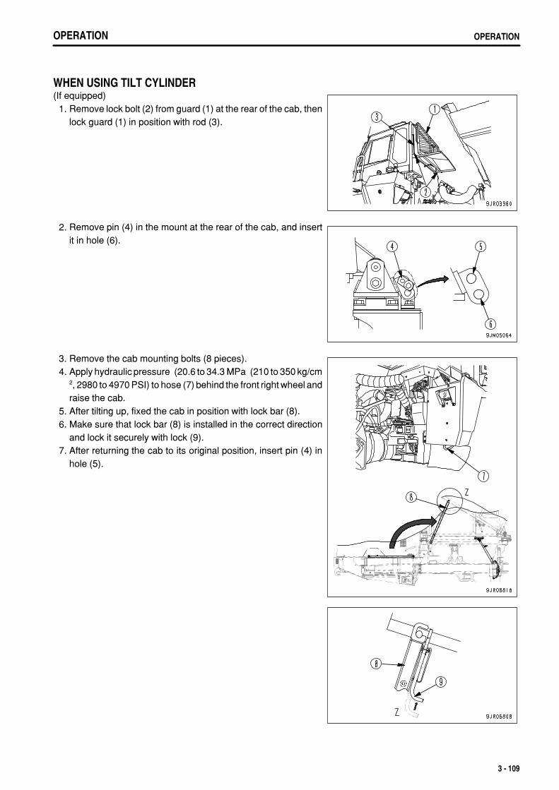
.
OPERATION OPERATION
WHEN USING TILT CYLINDER(If equipped) 1. Remove lock bolt (2) from guard (1) at the rear of the cab, then
lock guard (1) in position with rod (3).
2. Remove pin (4) in the mount at the rear of the cab, and insertit in hole (6).
3. Remove the cab mounting bolts (8 pieces). 4. Apply hydraulic pressure (20.6 to 34.3 MPa (210 to 350 kg/cm
2, 2980 to 4970 PSI) to hose (7) behind the front right wheel andraise the cab.
5. After tilting up, fixed the cab in position with lock bar (8). 6. Make sure that lock bar (8) is installed in the correct direction
and lock it securely with lock (9). 7. After returning the cab to its original position, insert pin (4) in
hole (5).
3 - 109
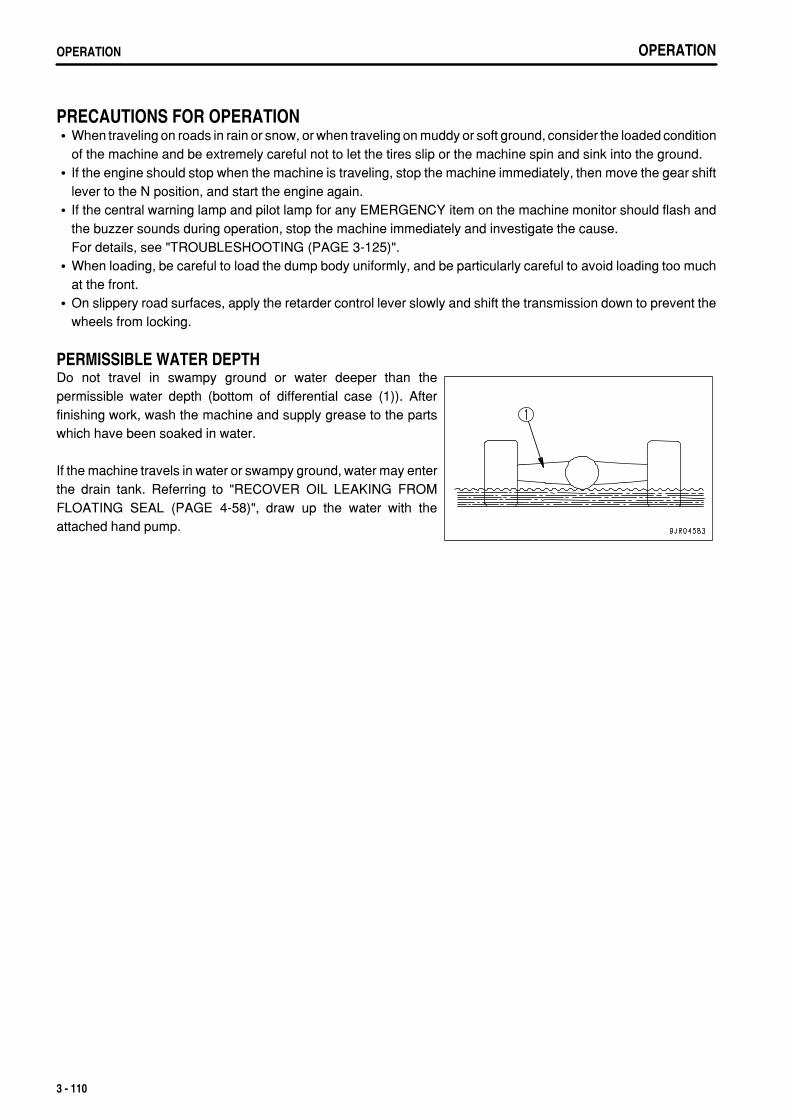
.
OPERATIONOPERATION
PRECAUTIONS FOR OPERATIONWhen traveling on roads in rain or snow, or when traveling on muddy or soft ground, consider the loaded conditionof the machine and be extremely careful not to let the tires slip or the machine spin and sink into the ground.If the engine should stop when the machine is traveling, stop the machine immediately, then move the gear shiftlever to the N position, and start the engine again.If the central warning lamp and pilot lamp for any EMERGENCY item on the machine monitor should flash andthe buzzer sounds during operation, stop the machine immediately and investigate the cause.For details, see "TROUBLESHOOTING (PAGE 3-125)".When loading, be careful to load the dump body uniformly, and be particularly careful to avoid loading too muchat the front.On slippery road surfaces, apply the retarder control lever slowly and shift the transmission down to prevent thewheels from locking.
PERMISSIBLE WATER DEPTHDo not travel in swampy ground or water deeper than thepermissible water depth (bottom of differential case (1)). Afterfinishing work, wash the machine and supply grease to the partswhich have been soaked in water.
If the machine travels in water or swampy ground, water may enterthe drain tank. Referring to "RECOVER OIL LEAKING FROMFLOATING SEAL (PAGE 4-58)", draw up the water with theattached hand pump.
3 - 110
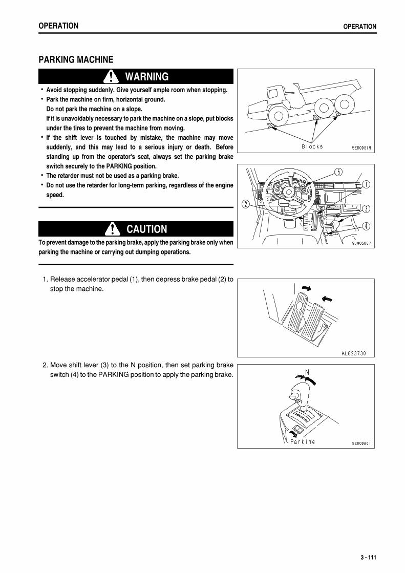
.
OPERATION OPERATION
PARKING MACHINE
WARNINGAvoid stopping suddenly. Give yourself ample room when stopping.Park the machine on firm, horizontal ground.Do not park the machine on a slope.If it is unavoidably necessary to park the machine on a slope, put blocksunder the tires to prevent the machine from moving.If the shift lever is touched by mistake, the machine may movesuddenly, and this may lead to a serious injury or death. Beforestanding up from the operator's seat, always set the parking brakeswitch securely to the PARKING position.The retarder must not be used as a parking brake.Do not use the retarder for long-term parking, regardless of the enginespeed.
CAUTIONTo prevent damage to the parking brake, apply the parking brake only whenparking the machine or carrying out dumping operations.
1. Release accelerator pedal (1), then depress brake pedal (2) tostop the machine.
2. Move shift lever (3) to the N position, then set parking brakeswitch (4) to the PARKING position to apply the parking brake.
3 - 111
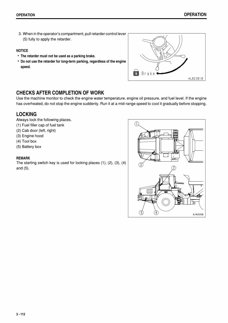
.
OPERATIONOPERATION OPERATIONOPERATION
3. When in the operator's compartment, pull retarder control lever(5) fully to apply the retarder.
NOTICEThe retarder must not be used as a parking brake.Do not use the retarder for long-term parking, regardless of the enginespeed.
CHECKS AFTER COMPLETION OF WORKUse the machine monitor to check the engine water temperature, engine oil pressure, and fuel level. If the enginehas overheated, do not stop the engine suddenly. Run it at a mid-range speed to cool it gradually before stopping.
LOCKINGAlways lock the following places.(1) Fuel filler cap of fuel tank(2) Cab door (left, right)(3) Engine hood(4) Tool box(5) Battery box
REMARKThe starting switch key is used for locking places (1), (2), (3), (4)and (5).
3 - 112
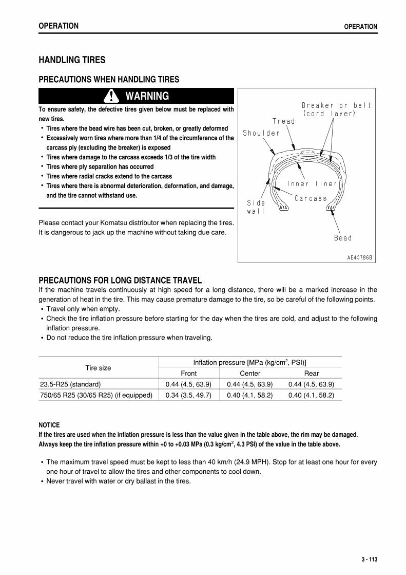
.
OPERATION OPERATION
HANDLING TIRES
PRECAUTIONS WHEN HANDLING TIRES
WARNINGTo ensure safety, the defective tires given below must be replaced withnew tires.
Tires where the bead wire has been cut, broken, or greatly deformedExcessively worn tires where more than 1/4 of the circumference of thecarcass ply (excluding the breaker) is exposedTires where damage to the carcass exceeds 1/3 of the tire widthTires where ply separation has occurredTires where radial cracks extend to the carcassTires where there is abnormal deterioration, deformation, and damage,and the tire cannot withstand use.
Please contact your Komatsu distributor when replacing the tires.It is dangerous to jack up the machine without taking due care.
PRECAUTIONS FOR LONG DISTANCE TRAVELIf the machine travels continuously at high speed for a long distance, there will be a marked increase in thegeneration of heat in the tire. This may cause premature damage to the tire, so be careful of the following points.
Travel only when empty.Check the tire inflation pressure before starting for the day when the tires are cold, and adjust to the followinginflation pressure.Do not reduce the tire inflation pressure when traveling.
Tire sizeInflation pressure [MPa (kg/cm2, PSI)]
Front Center Rear
23.5-R25 (standard) 0.44 (4.5, 63.9) 0.44 (4.5, 63.9) 0.44 (4.5, 63.9)
750/65 R25 (30/65 R25) (if equipped) 0.34 (3.5, 49.7) 0.40 (4.1, 58.2) 0.40 (4.1, 58.2)
NOTICEIf the tires are used when the inflation pressure is less than the value given in the table above, the rim may be damaged.Always keep the tire inflation pressure within +0 to +0.03 MPa (0.3 kg/cm2, 4.3 PSI) of the value in the table above.
The maximum travel speed must be kept to less than 40 km/h (24.9 MPH). Stop for at least one hour for everyone hour of travel to allow the tires and other components to cool down.Never travel with water or dry ballast in the tires.
3 - 113
.
OPERATIONDETERMINING AND MAINTAINING TRAVEL ROAD
DETERMINING AND MAINTAINING TRAVEL ROADDetermining and traveling the road in the jobsite is an extremely important factor both for reasons of safety and forreducing the cycle time.To ensure safety in operations, do as follows.
DETERMINING TRAVEL ROADAs far as possible, restrict the travel road to one-way travel.If it is impossible to keep to one-way traffic, make the road with ample width to enable trucks traveling in oppositedirections to pass each other. If it is impossible to provide a sufficient road width, provide passing places atvarious points along the road.Always design the road so that the loaded truck passes on the side closest to the hill face.If there are curves with poor visibility along the road, set up mirrors.In places where the road should is weak or likely to collapse, set up a sign at a point at least 1.5 m (4 ft 11 in) fromthe road shoulder to warn of the danger.It is important to set up lighting or reflectors to enable the road to be traveled at night.The grade of slope should be kept within 10% (approx. 6°) as far as possible, and emergency escape pointsshould be set up on downhill slopes in case of any brake failure.Make the road as straight as possible, and particularly in intermediate areas with curves, where the machine istraveling at high speed, make the radius of the curve as large as possible.Small S curves are particularly dangerous, so avoid such curves. The radius of the curve must be a minimum of12 to 15 m (39 ft 4 in to 49 ft 3 in).Make the radius of curves as large as possible.Make the road wider at curves than it is in straight areas.Make the outside of the curve slightly higher.Be particularly careful to strengthen the road shoulder on the outside of curve.As far as possible, design the road so that no other roads cross it. In particular, if roads cross at an angle onslopes, a stepped difference is formed in the road. This is extremely dangerous, as it causes the machine to rollwhen traveling at high speed.Cut the slope face to provide a special road for the trucks.
MAINTAINING TRAVEL ROADCarry out the necessary action according to the conditions to insure that the road can always be traveled in safety.
Remove any unevenness in the travel surface, sloping to the left or right, or drooping of the road shoulder. Makethe road of ample strength and remove such obstacles as rocks and tree stumps.Maintain the road from time to time with a bulldozer or motor grader.Spray the road with water at suitable intervals to prevent dust from rising and reducing the visibility.
3 - 114
.
OPERATION TRANSPORTATION
TRANSPORTATION
PRECAUTIONS WHEN TRANSPORTING
Always obey the traffic regulations when transporting the machine by road.
WARNINGThis machine must be disassembled for transportation. When transporting the machine, please consult your Komatsudistributor.
STEPS FOR TRANSPORTATIONAs a basic rule, always transport the machine on a trailer.When selecting the trailer, see the weights and dimensions given in "SPECIFICATIONS (PAGE 5-2)".Note that the specifications for the weights and dimensions for transportation differ according to the type of tires andtype of dump body.
3 - 115
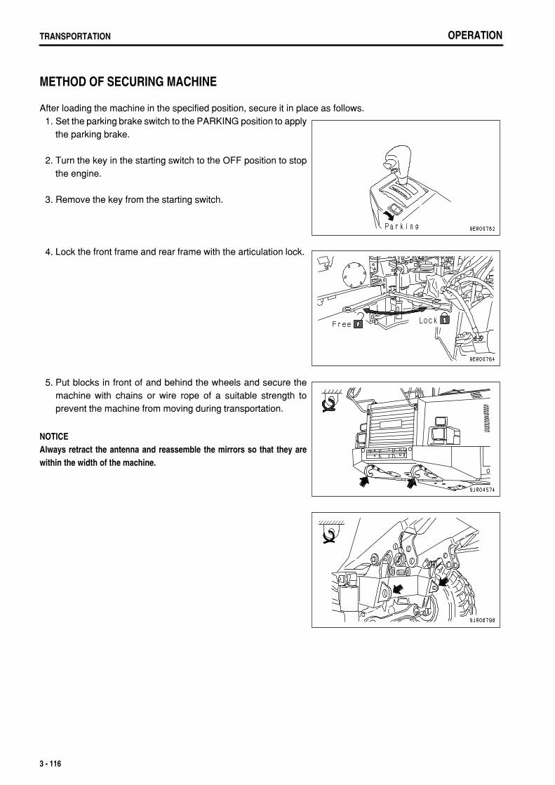
.
OPERATIONTRANSPORTATION
METHOD OF SECURING MACHINE
After loading the machine in the specified position, secure it in place as follows. 1. Set the parking brake switch to the PARKING position to apply
the parking brake.
2. Turn the key in the starting switch to the OFF position to stopthe engine.
3. Remove the key from the starting switch.
4. Lock the front frame and rear frame with the articulation lock.
5. Put blocks in front of and behind the wheels and secure themachine with chains or wire rope of a suitable strength toprevent the machine from moving during transportation.
NOTICEAlways retract the antenna and reassemble the mirrors so that they arewithin the width of the machine.
3 - 116
.
OPERATION TRANSPORTATION
METHOD OF LIFTING MACHINE
When lifting the machine at a port or any other place, always use the following procedure to lift it.
WARNINGThe operator carrying out the lifting operation using a crane must be a properly qualified crane operator.Never raise the machine with any worker on it.Always make sure that the wire rope is of ample strength for the weight of this machine.When lifting, keep the machine horizontal.Before starting the lifting operation, always stop the engine, apply the parking brake, and use the articulation lock to preventthe front frame from articulating.Never enter the area around or under the machine when it is raised.
Never try to lift the machine in any posture other than the posture given in the procedure below or using liftingequipment other than in the procedure below.There is a hazard that the machine may lose its balance.
NOTICEThis method of lifting applies to the standard specification machine.The method of lifting differs according to the attachments and options installed.For details of the procedure for machines that are not the standard specification, please consult your Komatsu distributor.
For the weight of the standard specification machine, see "WEIGHT TABLE (PAGE 3-118)".
NOTICEUse protectors to prevent the wire rope from being cut on sharp corners and to prevent the wire rope from cutting into themachine bodywork.When using a spreader bar, select an ample width to prevent contact with the machine.
Please consult your Komatsu distributor before carrying out lifting work.
3 - 117
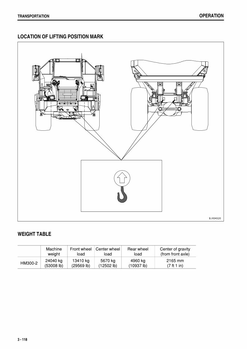
.
OPERATIONTRANSPORTATION
LOCATION OF LIFTING POSITION MARK
WEIGHT TABLE
Machineweight
Front wheelload
Center wheelload
Rear wheelload
Center of gravity(from front axle)
HM300-224040 kg(53008 lb)
13410 kg(29569 lb)
5670 kg(12502 lb)
4960 kg(10937 lb)
2165 mm(7 ft 1 in)
3 - 118
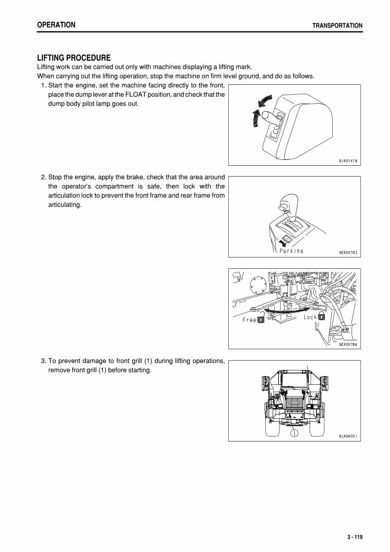
.
OPERATION TRANSPORTATION
LIFTING PROCEDURELifting work can be carried out only with machines displaying a lifting mark.When carrying out the lifting operation, stop the machine on firm level ground, and do as follows. 1. Start the engine, set the machine facing directly to the front,
place the dump lever at the FLOAT position, and check that thedump body pilot lamp goes out.
2. Stop the engine, apply the brake, check that the area aroundthe operator's compartment is safe, then lock with thearticulation lock to prevent the front frame and rear frame fromarticulating.
3. To prevent damage to front grill (1) during lifting operations,remove front grill (1) before starting.
3 - 119
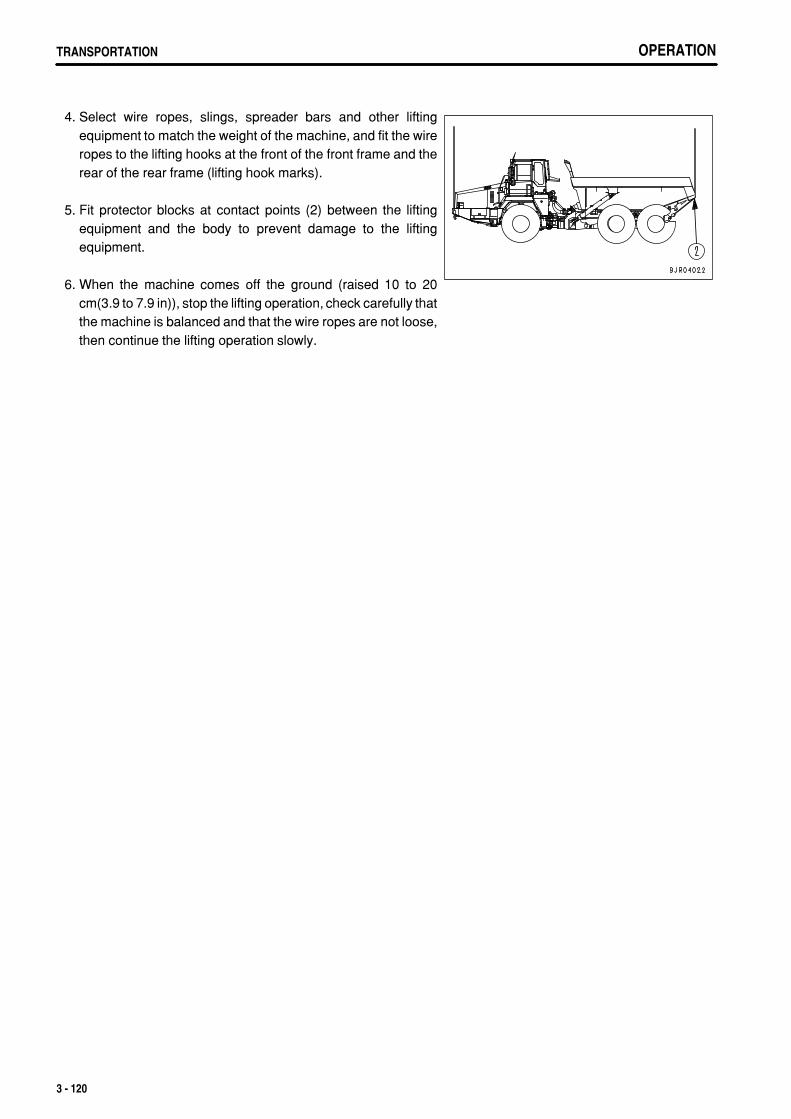
.
OPERATIONTRANSPORTATION OPERATIONTRANSPORTATION
4. Select wire ropes, slings, spreader bars and other liftingequipment to match the weight of the machine, and fit the wireropes to the lifting hooks at the front of the front frame and therear of the rear frame (lifting hook marks).
5. Fit protector blocks at contact points (2) between the liftingequipment and the body to prevent damage to the liftingequipment.
6. When the machine comes off the ground (raised 10 to 20cm(3.9 to 7.9 in)), stop the lifting operation, check carefully thatthe machine is balanced and that the wire ropes are not loose,then continue the lifting operation slowly.
3 - 120
.
OPERATION COLD WEATHER OPERATION
COLD WEATHER OPERATION
PRECAUTIONS FOR LOW TEMPERATUREIf the temperature becomes low, it becomes difficult to start the engine, and the coolant may freeze, so do as follows.
FUEL AND LUBRICANTSChange to fuel and oil with low viscosity for all components. For details of the specified visicosity, see"RECOMMENDED FUEL, COOLANT, AND LUBRICANT (PAGE 4-10)".
COOLANT
WARNINGAntifreeze is toxic. Be careful not to get it into your eyes or on your skin. If it should get into your eyes or on your skin, washit off with large amounts of fresh water and see a doctor at once.When changing the coolant or when handling coolant containing antifreeze that has been drained when repairing the radiator,please contact your Komatsu distributor or request a specialist company to carry out the operation. Antifreeze is toxic. Do notlet it flow into drainage ditches or spray it onto the ground surface.Antifreeze is flammable. Do not bring any flame close. Do not smoke when handling antifreeze.
NOTICEUse Komatsu Supercoolant (AF-NAC) wherever available, or use permanent type antifreeze coolant.Never use methanol, ethanol, or propanol-based antifreeze.Do not use any water leakage prevention agent, either alone, or in combination with antifreeze.Do not mix one brand of antifreeze with a different brand.When using Komatsu Supercoolant (AF-NAC), there is no need to use a corrosion resistor. For details, see "CLEAN INSIDE OFCOOLING SYSTEM (PAGE 4-26)".
For details on the amount of antifreeze mixture and on when to change the coolant, see "CLEAN INSIDE OFCOOLING SYSTEM (PAGE 4-26)".
3 - 121
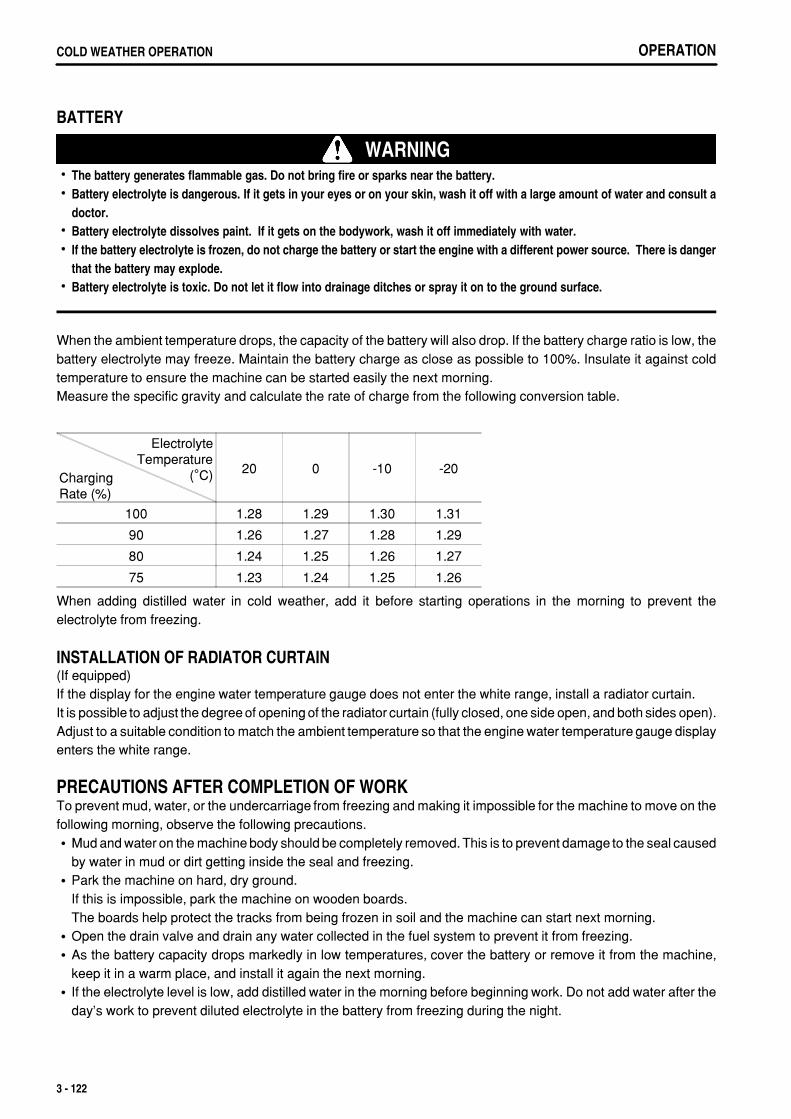
.
OPERATIONCOLD WEATHER OPERATION
BATTERY
WARNINGThe battery generates flammable gas. Do not bring fire or sparks near the battery.Battery electrolyte is dangerous. If it gets in your eyes or on your skin, wash it off with a large amount of water and consult adoctor.Battery electrolyte dissolves paint. If it gets on the bodywork, wash it off immediately with water.If the battery electrolyte is frozen, do not charge the battery or start the engine with a different power source. There is dangerthat the battery may explode.Battery electrolyte is toxic. Do not let it flow into drainage ditches or spray it on to the ground surface.
When the ambient temperature drops, the capacity of the battery will also drop. If the battery charge ratio is low, thebattery electrolyte may freeze. Maintain the battery charge as close as possible to 100%. Insulate it against coldtemperature to ensure the machine can be started easily the next morning.Measure the specific gravity and calculate the rate of charge from the following conversion table.
ElectrolyteTemperature
(°C)ChargingRate (%)
20 0 -10 -20
100 1.28 1.29 1.30 1.31
90 1.26 1.27 1.28 1.29
80 1.24 1.25 1.26 1.27
75 1.23 1.24 1.25 1.26
When adding distilled water in cold weather, add it before starting operations in the morning to prevent theelectrolyte from freezing.
INSTALLATION OF RADIATOR CURTAIN(If equipped)If the display for the engine water temperature gauge does not enter the white range, install a radiator curtain.It is possible to adjust the degree of opening of the radiator curtain (fully closed, one side open, and both sides open).Adjust to a suitable condition to match the ambient temperature so that the engine water temperature gauge displayenters the white range.
PRECAUTIONS AFTER COMPLETION OF WORKTo prevent mud, water, or the undercarriage from freezing and making it impossible for the machine to move on thefollowing morning, observe the following precautions.
Mud and water on the machine body should be completely removed. This is to prevent damage to the seal causedby water in mud or dirt getting inside the seal and freezing.Park the machine on hard, dry ground.If this is impossible, park the machine on wooden boards.The boards help protect the tracks from being frozen in soil and the machine can start next morning.Open the drain valve and drain any water collected in the fuel system to prevent it from freezing.As the battery capacity drops markedly in low temperatures, cover the battery or remove it from the machine,keep it in a warm place, and install it again the next morning.If the electrolyte level is low, add distilled water in the morning before beginning work. Do not add water after theday's work to prevent diluted electrolyte in the battery from freezing during the night.
3 - 122

.
OPERATION COLD WEATHER OPERATION
AFTER COLD WEATHERWhen the season changes and the weather becomes warmer, do as follows.
Replace the fuel and oil for all parts with oil of the viscosity specified.For details, see "RECOMMENDED FUEL, COOLANT, AND LUBRICANT (PAGE 4-10)".
3 - 123
.
OPERATIONLONG-TERM STORAGE
LONG-TERM STORAGE
BEFORE STORAGEWhen keeping in long-term storage (more than one month), store as follows.
After every part is washed and dried, house the machine in a dry building. Never leave it outdoors.In case it is indispensable to leave it outdoors, park the machine on the flat ground and cover it with canvas etc.Completely fill the fuel tank. This prevents moisture from collecting.Lubricate and change the oil before storage.Coat the exposed portion of the hydraulic cylinder piston rod with grease.Disconnect the negative terminals of the battery and cover it or remove it from the machine and store it separately.Apply the parking brake.Set the tire inflation pressure for each tire to within the range of the specified inflation pressure for the type of tire.Push the retarder control lever forward to the OFF position.Place the gear shift lever at the N position and turn the starting switch OFF.To prevent corrosion, be sure to fill the cooling system with Supercoolant (AF-NAC) or permanent type antifreeze(density between 30% and 68%).
DURING STORAGE
WARNINGIf it is necessary to perform the rust-prevention operation while the machine is indoors, open the doors and windows to improveventilation and prevent gas poisoning.
During the storage period, operate the machine once a month to prevent loss of the oil film at the lubricated parts.At the same time, charge the battery.Before operating the work equipment, wipe off all the grease from hydraulic piston rods.
AFTER STORAGE
NOTICEIf the machine has been stored without carrying out the monthly rust-prevention operation, consult your Komatsu distributorbefore using it.
When using the machine after long-term storage, do as follows before using it.Wipe off the grease from the hydraulic cylinder rods.Add oil and grease at all lubrication points.When the machine is stored for a long period, moisture in the air will mix with the oil. Check the oil before and afterstarting the engine. If there is water in the oil, change all the oil.
PRECAUTIONS BEFORE TRAVELING AFTER LONG-TERM STORAGE 1. Check all the oil and water levels before traveling. 2. When traveling after long-term storage, travel forward at a speed of 10 to 15 km/h (6.2 to 9.3 MPH) for 5 minutes
or 1 km to run the machine in, then change to normal travel.
3 - 124
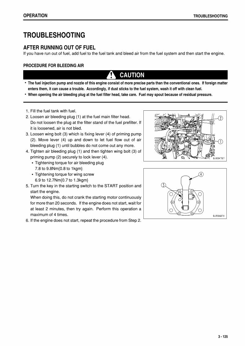
.
OPERATION TROUBLESHOOTING
TROUBLESHOOTING
AFTER RUNNING OUT OF FUELIf you have run out of fuel, add fuel to the fuel tank and bleed air from the fuel system and then start the engine.
PROCEDURE FOR BLEEDING AIR
CAUTIONThe fuel injection pump and nozzle of this engine consist of more precise parts than the conventional ones. If foreign matterenters them, it can cause a trouble. Accordingly, if dust sticks to the fuel system, wash it off with clean fuel.When opening the air bleeding plug at the fuel filter head, take care. Fuel may spout because of residual pressure.
1. Fill the fuel tank with fuel. 2. Loosen air bleeding plug (1) at the fuel main filter head.
Do not loosen the plug at the filter stand of the fuel prefilter. Ifit is loosened, air is not bled.
3. Loosen wing bolt (3) which is fixing lever (4) of priming pump(2). Move lever (4) up and down to let fuel flow out of airbleeding plug (1) until bubbles do not come out any more.
4. Tighten air bleeding plug (1) and then tighten wing bolt (3) ofpriming pump (2) securely to lock lever (4).
Tightening torque for air bleeding plug7.8 to 9.8Nm{0.8 to 1kgm}Tightening torque for wing screw6.9 to 12.7Nm{0.7 to 1.3kgm}
5. Turn the key in the starting switch to the START position andstart the engine.When doing this, do not crank the starting motor continuouslyfor more than 20 seconds. If the engine does not start, wait forat least 2 minutes, then try again. Perform this operation amaximum of 4 times.
6. If the engine does not start, repeat the procedure from Step 2.
3 - 125
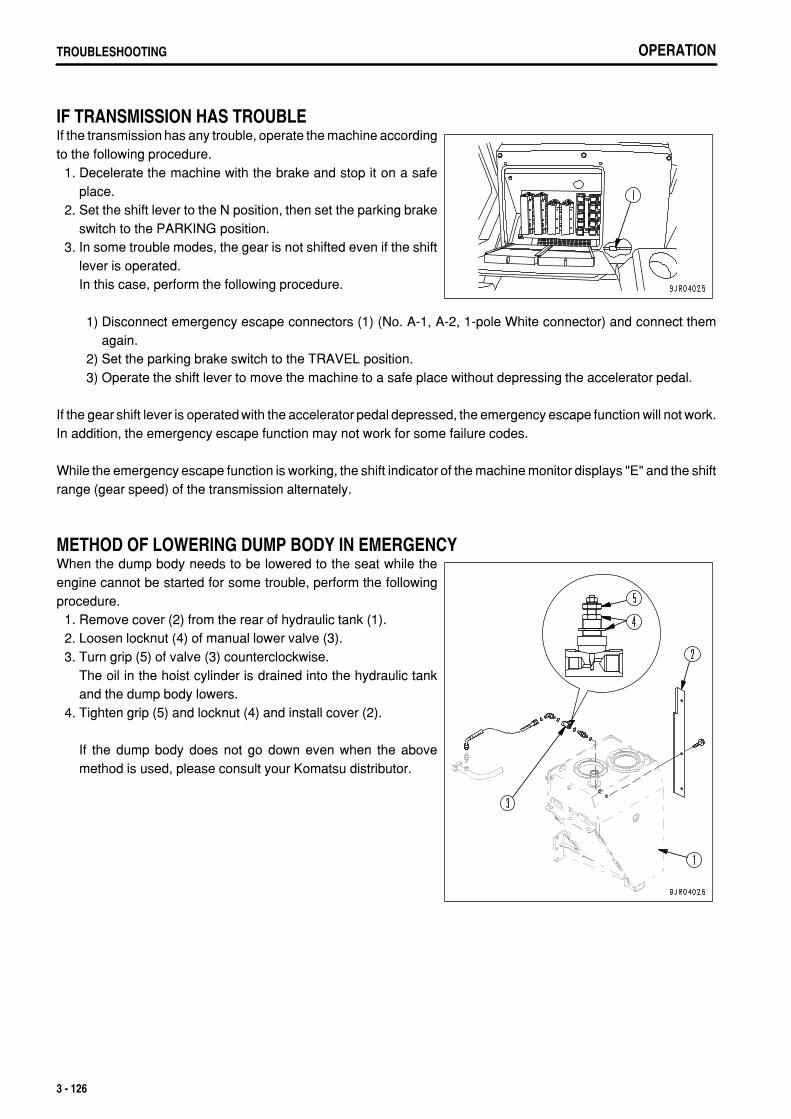
.
OPERATIONTROUBLESHOOTING
IF TRANSMISSION HAS TROUBLEIf the transmission has any trouble, operate the machine accordingto the following procedure. 1. Decelerate the machine with the brake and stop it on a safe
place. 2. Set the shift lever to the N position, then set the parking brake
switch to the PARKING position. 3. In some trouble modes, the gear is not shifted even if the shift
lever is operated.In this case, perform the following procedure.
1) Disconnect emergency escape connectors (1) (No. A-1, A-2, 1-pole White connector) and connect themagain.
2) Set the parking brake switch to the TRAVEL position. 3) Operate the shift lever to move the machine to a safe place without depressing the accelerator pedal.
If the gear shift lever is operated with the accelerator pedal depressed, the emergency escape function will not work.In addition, the emergency escape function may not work for some failure codes.
While the emergency escape function is working, the shift indicator of the machine monitor displays "E" and the shiftrange (gear speed) of the transmission alternately.
METHOD OF LOWERING DUMP BODY IN EMERGENCYWhen the dump body needs to be lowered to the seat while theengine cannot be started for some trouble, perform the followingprocedure. 1. Remove cover (2) from the rear of hydraulic tank (1). 2. Loosen locknut (4) of manual lower valve (3). 3. Turn grip (5) of valve (3) counterclockwise.
The oil in the hoist cylinder is drained into the hydraulic tankand the dump body lowers.
4. Tighten grip (5) and locknut (4) and install cover (2).
If the dump body does not go down even when the abovemethod is used, please consult your Komatsu distributor.
3 - 126
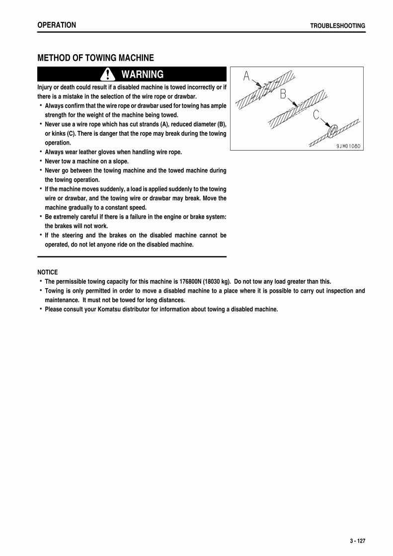
.
OPERATION TROUBLESHOOTING
METHOD OF TOWING MACHINE
WARNINGInjury or death could result if a disabled machine is towed incorrectly or ifthere is a mistake in the selection of the wire rope or drawbar.
Always confirm that the wire rope or drawbar used for towing has amplestrength for the weight of the machine being towed.Never use a wire rope which has cut strands (A), reduced diameter (B),or kinks (C). There is danger that the rope may break during the towingoperation.Always wear leather gloves when handling wire rope.Never tow a machine on a slope.Never go between the towing machine and the towed machine duringthe towing operation.If the machine moves suddenly, a load is applied suddenly to the towingwire or drawbar, and the towing wire or drawbar may break. Move themachine gradually to a constant speed.Be extremely careful if there is a failure in the engine or brake system:the brakes will not work.If the steering and the brakes on the disabled machine cannot beoperated, do not let anyone ride on the disabled machine.
NOTICEThe permissible towing capacity for this machine is 176800N (18030 kg). Do not tow any load greater than this.Towing is only permitted in order to move a disabled machine to a place where it is possible to carry out inspection andmaintenance. It must not be towed for long distances.Please consult your Komatsu distributor for information about towing a disabled machine.
3 - 127
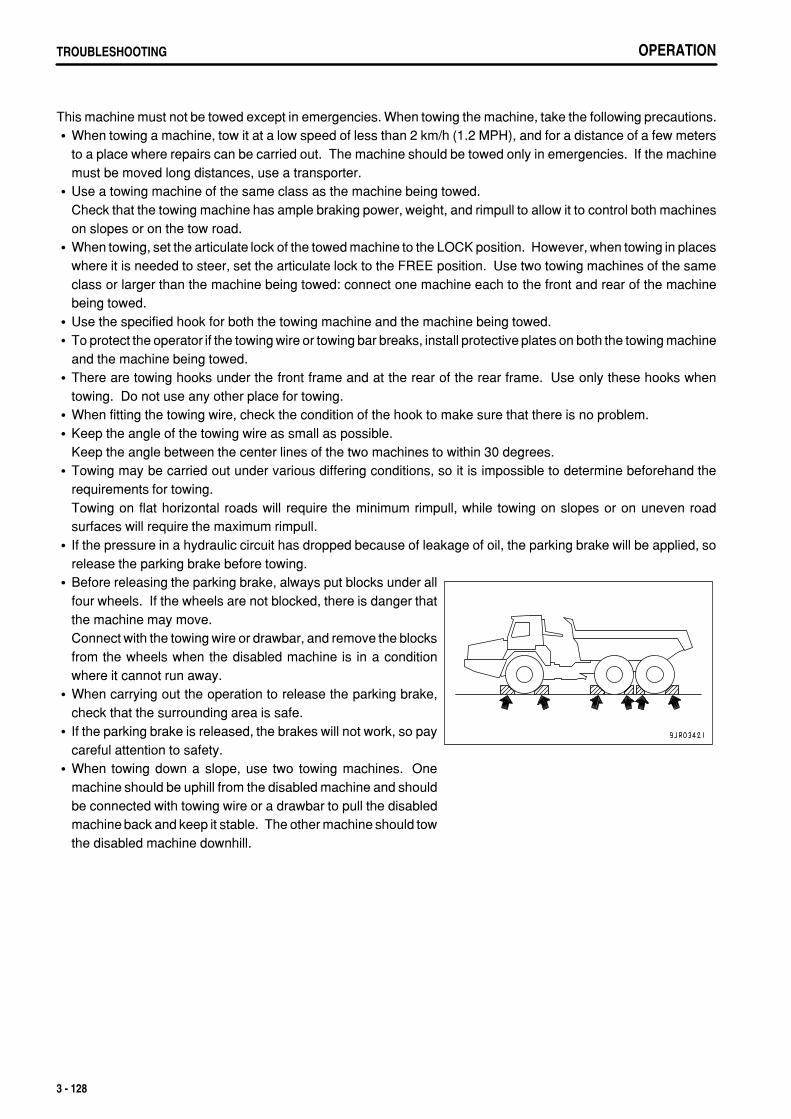
.
OPERATIONTROUBLESHOOTING
This machine must not be towed except in emergencies. When towing the machine, take the following precautions.When towing a machine, tow it at a low speed of less than 2 km/h (1.2 MPH), and for a distance of a few metersto a place where repairs can be carried out. The machine should be towed only in emergencies. If the machinemust be moved long distances, use a transporter.Use a towing machine of the same class as the machine being towed.Check that the towing machine has ample braking power, weight, and rimpull to allow it to control both machineson slopes or on the tow road.When towing, set the articulate lock of the towed machine to the LOCK position. However, when towing in placeswhere it is needed to steer, set the articulate lock to the FREE position. Use two towing machines of the sameclass or larger than the machine being towed: connect one machine each to the front and rear of the machinebeing towed.Use the specified hook for both the towing machine and the machine being towed.To protect the operator if the towing wire or towing bar breaks, install protective plates on both the towing machineand the machine being towed.There are towing hooks under the front frame and at the rear of the rear frame. Use only these hooks whentowing. Do not use any other place for towing.When fitting the towing wire, check the condition of the hook to make sure that there is no problem.Keep the angle of the towing wire as small as possible. Keep the angle between the center lines of the two machines to within 30 degrees.Towing may be carried out under various differing conditions, so it is impossible to determine beforehand therequirements for towing.Towing on flat horizontal roads will require the minimum rimpull, while towing on slopes or on uneven roadsurfaces will require the maximum rimpull.If the pressure in a hydraulic circuit has dropped because of leakage of oil, the parking brake will be applied, sorelease the parking brake before towing.Before releasing the parking brake, always put blocks under allfour wheels. If the wheels are not blocked, there is danger thatthe machine may move.Connect with the towing wire or drawbar, and remove the blocksfrom the wheels when the disabled machine is in a conditionwhere it cannot run away.When carrying out the operation to release the parking brake,check that the surrounding area is safe.If the parking brake is released, the brakes will not work, so paycareful attention to safety.When towing down a slope, use two towing machines. Onemachine should be uphill from the disabled machine and shouldbe connected with towing wire or a drawbar to pull the disabledmachine back and keep it stable. The other machine should towthe disabled machine downhill.
3 - 128
.
OPERATION TROUBLESHOOTING
WHEN ENGINE RUNS
If the transmission and steering wheel can be operated, and the engine is running, it is possible to tow themachine out of mud or to move it for a short distance to the edge of the road.Check the effect of the brakes, and if the brakes do not work properly, take the action given in "When engine doesnot run".Check if it is possible to steer the machine. If the machine cannot be steered, follow the procedure given in"WHEN ENGINE DOES NOT RUN".The operator should sit on the machine being towed and operate the steering in the direction that the machineis towed.Always run the engine to allow the steering and brakes to be used.
WHEN ENGINE DOES NOT RUN
The brakes will not work, so be extremely careful.Connect the towing machine securely to the towed machine. Use two towing machines of the same class orlarger than the machine being towed: connect one machine each to the front and rear of the machine being towed.If it is necessary to change the direction of the machine being towed, it is possible to use the emergency steering,but it can be used for a maximum of only 90 seconds.If the emergency steering cannot be used, disconnect two hydraulic hoses each on the left and right from thesteering cylinders, then carry out the towing operation. When removing the hoses, block the hoses with plugs andfit oil containers to the mouthpiece of the cylinder to prevent oil from draining to the ground.
3 - 129
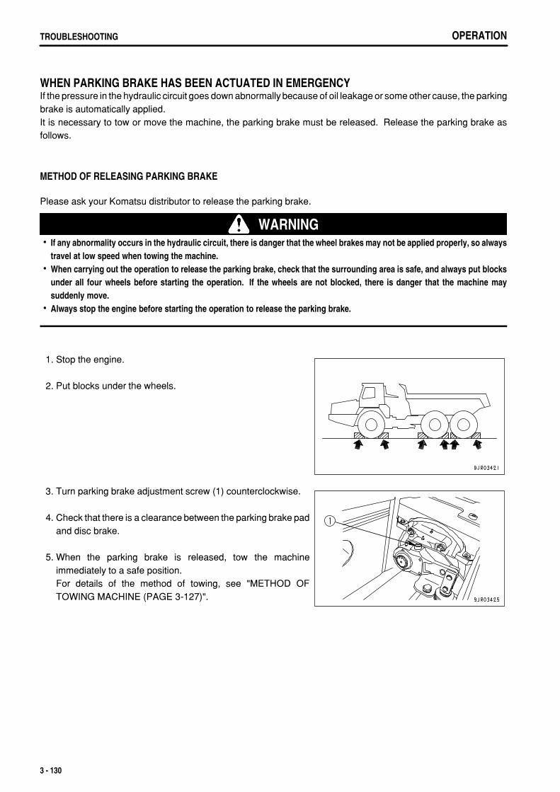
.
OPERATIONTROUBLESHOOTING
WHEN PARKING BRAKE HAS BEEN ACTUATED IN EMERGENCYIf the pressure in the hydraulic circuit goes down abnormally because of oil leakage or some other cause, the parkingbrake is automatically applied.It is necessary to tow or move the machine, the parking brake must be released. Release the parking brake asfollows.
METHOD OF RELEASING PARKING BRAKE
Please ask your Komatsu distributor to release the parking brake.
WARNINGIf any abnormality occurs in the hydraulic circuit, there is danger that the wheel brakes may not be applied properly, so alwaystravel at low speed when towing the machine.When carrying out the operation to release the parking brake, check that the surrounding area is safe, and always put blocksunder all four wheels before starting the operation. If the wheels are not blocked, there is danger that the machine maysuddenly move.Always stop the engine before starting the operation to release the parking brake.
1. Stop the engine.
2. Put blocks under the wheels.
3. Turn parking brake adjustment screw (1) counterclockwise.
4. Check that there is a clearance between the parking brake padand disc brake.
5. When the parking brake is released, tow the machineimmediately to a safe position.For details of the method of towing, see "METHOD OFTOWING MACHINE (PAGE 3-127)".
3 - 130

.
OPERATION TROUBLESHOOTING
IF BATTERY IS DISCHARGED
WARNINGIt is dangerous to charge a battery when mounted on a machine. Make sure that it is dismounted before charging.When checking or handling the battery, stop the engine and turn the starting switch key to the OFF position.The battery generates hydrogen gas, so there is a hazard of explosion. Do not bring lighted cigarettes near the battery, or doanything that will cause sparks.Battery electrolyte is dilute sulfuric acid, and it will attack your clothes and skin. If it gets on your clothes or on your skin,immediately wash it off with a large amount of water. If it gets in your eyes, wash it out with fresh water and consult a doctor.When handling batteries, always wear safety glasses and rubber gloves.When removing the battery, first disconnect the cable from the ground (normally the negative (-) terminal). When installing,install the positive (+) terminal first.If a tool touches the positive terminal and the chassis, there is danger that it will cause a spark, so be extremely careful.If the terminals are loose, there is danger that the defective contact may generate sparks that will cause an explosion.When removing or installing the terminals, check which is the positive (+) terminal and which is the negative (-) terminal.
REMOVAL AND INSTALLATION OF BATTERYBefore removing the battery, remove the ground cable (normallyconnected to the negative (-) terminal).If any tool touches between the positive terminal and thechassis, there is a hazard of sparks being generated.
When installing the battery, connect the ground cable last.
3 - 131
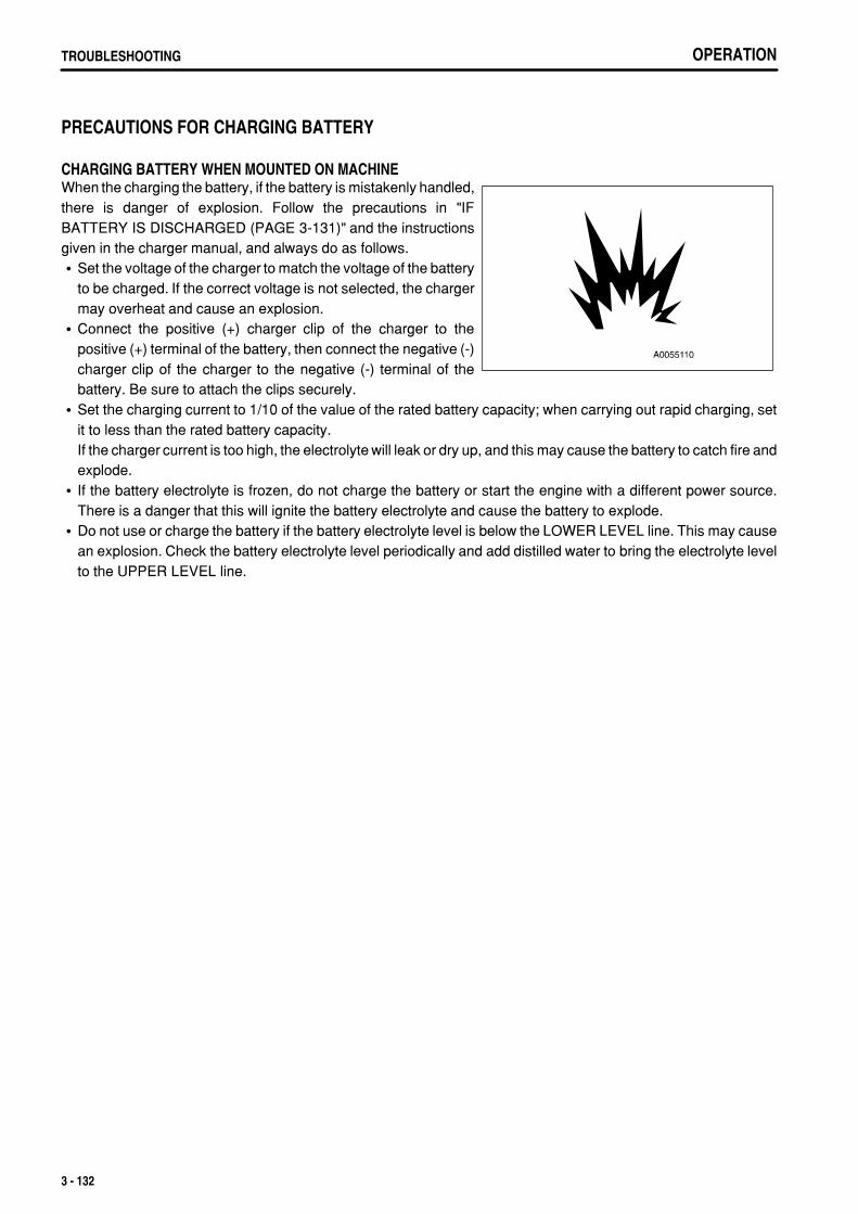
.
OPERATIONTROUBLESHOOTING
PRECAUTIONS FOR CHARGING BATTERY
CHARGING BATTERY WHEN MOUNTED ON MACHINEWhen the charging the battery, if the battery is mistakenly handled,there is danger of explosion. Follow the precautions in "IFBATTERY IS DISCHARGED (PAGE 3-131)" and the instructionsgiven in the charger manual, and always do as follows.
Set the voltage of the charger to match the voltage of the batteryto be charged. If the correct voltage is not selected, the chargermay overheat and cause an explosion.Connect the positive (+) charger clip of the charger to thepositive (+) terminal of the battery, then connect the negative (-)charger clip of the charger to the negative (-) terminal of thebattery. Be sure to attach the clips securely.Set the charging current to 1/10 of the value of the rated battery capacity; when carrying out rapid charging, setit to less than the rated battery capacity.If the charger current is too high, the electrolyte will leak or dry up, and this may cause the battery to catch fire andexplode.If the battery electrolyte is frozen, do not charge the battery or start the engine with a different power source.There is a danger that this will ignite the battery electrolyte and cause the battery to explode.Do not use or charge the battery if the battery electrolyte level is below the LOWER LEVEL line. This may causean explosion. Check the battery electrolyte level periodically and add distilled water to bring the electrolyte levelto the UPPER LEVEL line.
3 - 132
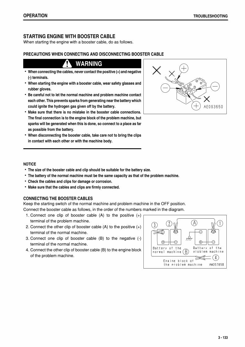
.
OPERATION TROUBLESHOOTING
STARTING ENGINE WITH BOOSTER CABLEWhen starting the engine with a booster cable, do as follows.
PRECAUTIONS WHEN CONNECTING AND DISCONNECTING BOOSTER CABLE
WARNINGWhen connecting the cables, never contact the positive (+) and negative(-) terminals.When starting the engine with a booster cable, wear safety glasses andrubber gloves.Be careful not to let the normal machine and problem machine contacteach other. This prevents sparks from generating near the battery whichcould ignite the hydrogen gas given off by the battery.Make sure that there is no mistake in the booster cable connections.The final connection is to the engine block of the problem machine, butsparks will be generated when this is done, so connect to a place as faras possible from the battery.When disconnecting the booster cable, take care not to bring the clipsin contact with each other or with the machine body.
NOTICEThe size of the booster cable and clip should be suitable for the battery size.The battery of the normal machine must be the same capacity as that of the problem machine.Check the cables and clips for damage or corrosion.Make sure that the cables and clips are firmly connected.
CONNECTING THE BOOSTER CABLESKeep the starting switch of the normal machine and problem machine in the OFF position.Connect the booster cable as follows, in the order of the numbers marked in the diagram. 1. Connect one clip of booster cable (A) to the positive (+)
terminal of the problem machine. 2. Connect the other clip of booster cable (A) to the positive (+)
terminal of the normal machine. 3. Connect one clip of booster cable (B) to the negative (-)
terminal of the normal machine. 4. Connect the other clip of booster cable (B) to the engine block
of the problem machine.
3 - 133
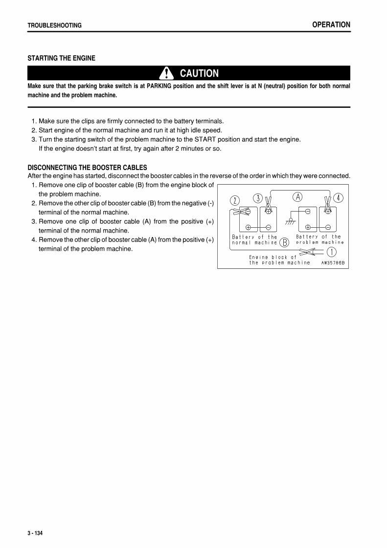
.
OPERATIONTROUBLESHOOTING
STARTING THE ENGINE
CAUTIONMake sure that the parking brake switch is at PARKING position and the shift lever is at N (neutral) position for both normalmachine and the problem machine.
1. Make sure the clips are firmly connected to the battery terminals. 2. Start engine of the normal machine and run it at high idle speed. 3. Turn the starting switch of the problem machine to the START position and start the engine.
If the engine doesn't start at first, try again after 2 minutes or so.
DISCONNECTING THE BOOSTER CABLESAfter the engine has started, disconnect the booster cables in the reverse of the order in which they were connected. 1. Remove one clip of booster cable (B) from the engine block of
the problem machine. 2. Remove the other clip of booster cable (B) from the negative (-)
terminal of the normal machine. 3. Remove one clip of booster cable (A) from the positive (+)
terminal of the normal machine. 4. Remove the other clip of booster cable (A) from the positive (+)
terminal of the problem machine.
3 - 134
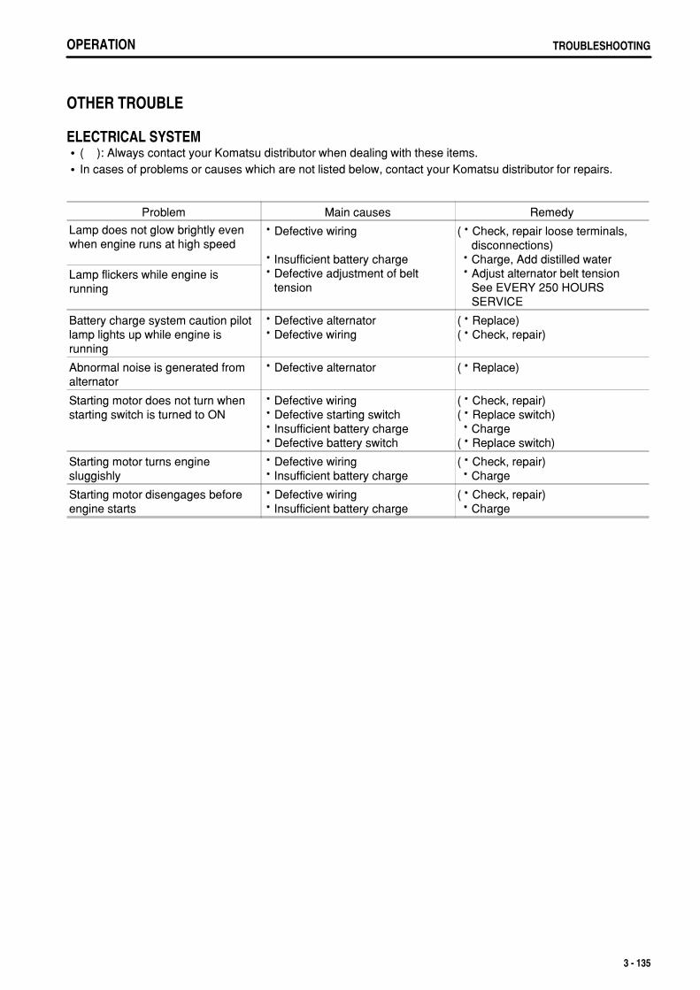
.
OPERATION TROUBLESHOOTING
OTHER TROUBLE
ELECTRICAL SYSTEM( ): Always contact your Komatsu distributor when dealing with these items.In cases of problems or causes which are not listed below, contact your Komatsu distributor for repairs.
Problem Main causes Remedy
Lamp does not glow brightly evenwhen engine runs at high speed
Defective wiring
Insufficient battery chargeDefective adjustment of belttension
( Check, repair loose terminals, disconnections)
Charge, Add distilled water Adjust alternator belt tension
See EVERY 250 HOURS SERVICE
Lamp flickers while engine isrunning
Battery charge system caution pilotlamp lights up while engine isrunning
Defective alternatorDefective wiring
( Replace)( Check, repair)
Abnormal noise is generated fromalternator
Defective alternator ( Replace)
Starting motor does not turn whenstarting switch is turned to ON
Defective wiringDefective starting switchInsufficient battery chargeDefective battery switch
( Check, repair)( Replace switch) Charge( Replace switch)
Starting motor turns enginesluggishly
Defective wiringInsufficient battery charge
( Check, repair) Charge
Starting motor disengages beforeengine starts
Defective wiringInsufficient battery charge
( Check, repair) Charge
3 - 135
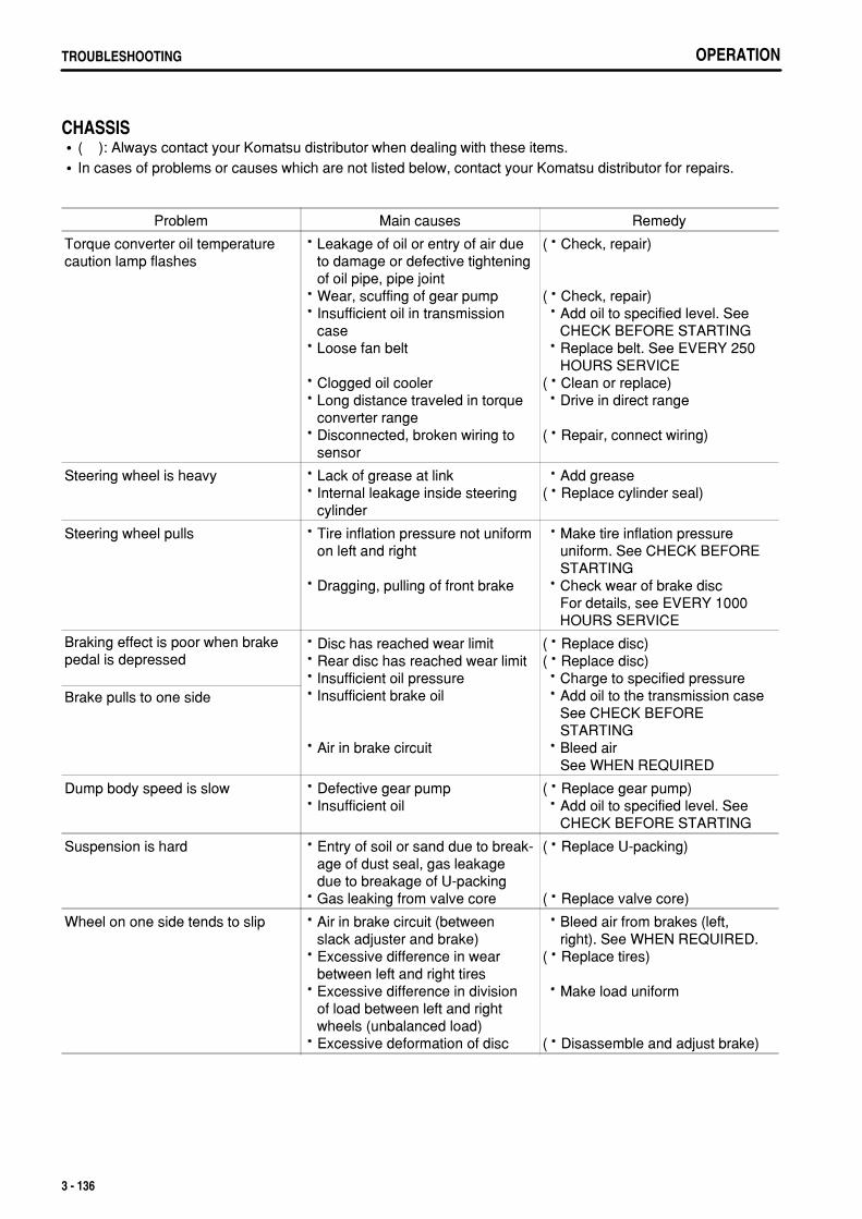
.
OPERATIONTROUBLESHOOTING
CHASSIS( ): Always contact your Komatsu distributor when dealing with these items.In cases of problems or causes which are not listed below, contact your Komatsu distributor for repairs.
Problem Main causes Remedy
Torque converter oil temperaturecaution lamp flashes
Leakage of oil or entry of air dueto damage or defective tighteningof oil pipe, pipe jointWear, scuffing of gear pumpInsufficient oil in transmissioncaseLoose fan belt
Clogged oil coolerLong distance traveled in torqueconverter rangeDisconnected, broken wiring tosensor
( Check, repair)
( Check, repair) Add oil to specified level. See
CHECK BEFORE STARTING Replace belt. See EVERY 250
HOURS SERVICE( Clean or replace) Drive in direct range
( Repair, connect wiring)
Steering wheel is heavy Lack of grease at linkInternal leakage inside steeringcylinder
Add grease( Replace cylinder seal)
Steering wheel pulls Tire inflation pressure not uniformon left and right
Dragging, pulling of front brake
Make tire inflation pressure uniform. See CHECK BEFORE STARTING
Check wear of brake disc For details, see EVERY 1000 HOURS SERVICE
Braking effect is poor when brakepedal is depressed
Disc has reached wear limitRear disc has reached wear limitInsufficient oil pressureInsufficient brake oil
Air in brake circuit
( Replace disc)( Replace disc) Charge to specified pressure Add oil to the transmission case
See CHECK BEFORE STARTING
Bleed air See WHEN REQUIRED
Brake pulls to one side
Dump body speed is slow Defective gear pumpInsufficient oil
( Replace gear pump) Add oil to specified level. See
CHECK BEFORE STARTING
Suspension is hard Entry of soil or sand due to break-age of dust seal, gas leakagedue to breakage of U-packingGas leaking from valve core
( Replace U-packing)
( Replace valve core)
Wheel on one side tends to slip Air in brake circuit (betweenslack adjuster and brake)Excessive difference in wearbetween left and right tiresExcessive difference in divisionof load between left and rightwheels (unbalanced load)Excessive deformation of disc
Bleed air from brakes (left, right). See WHEN REQUIRED.
( Replace tires)
Make load uniform
( Disassemble and adjust brake)
3 - 136
.
OPERATION TROUBLESHOOTING
IF ACCELERATOR PEDAL HAS FAILEDIn addition to the potentiometer detecting the pedal depression depth, the switch (check switch) is installed on theaccelerator pedal assembly in order to detect whether the accelerator pedal is depressed or not.If the pedal depression depth is not detected correctly due to a failure of the accelerator pedal or incorrect electricwiring, the engine controller controls the engine speed responding to the signal from this check switch. The engineruns at 1500 rpm when the accelerator pedal is depressed, while the engine runs at low idle when the pedal isreleased. The engine speed varies depending on the load.After using the accelerator pedal to move the machine to a safe place, check the service code and contact yourKomatsu distributor.There are two methods when operating the accelerator pedal: either release the pedal (check switch is OFF, lowidle), or depress the pedal fully (1500 rpm).If the accelerator pedal is held at an intermediate position, the system may not be able to judge if the acceleratorpedal is being operated or not.
REMARKIf the engine controller cannot perform normal reception of the signal of the accelerator pedal depth, the centralwarning lamp flashes and simultaneously the alarm buzzer sounds and user code 02 appears.
3 - 137
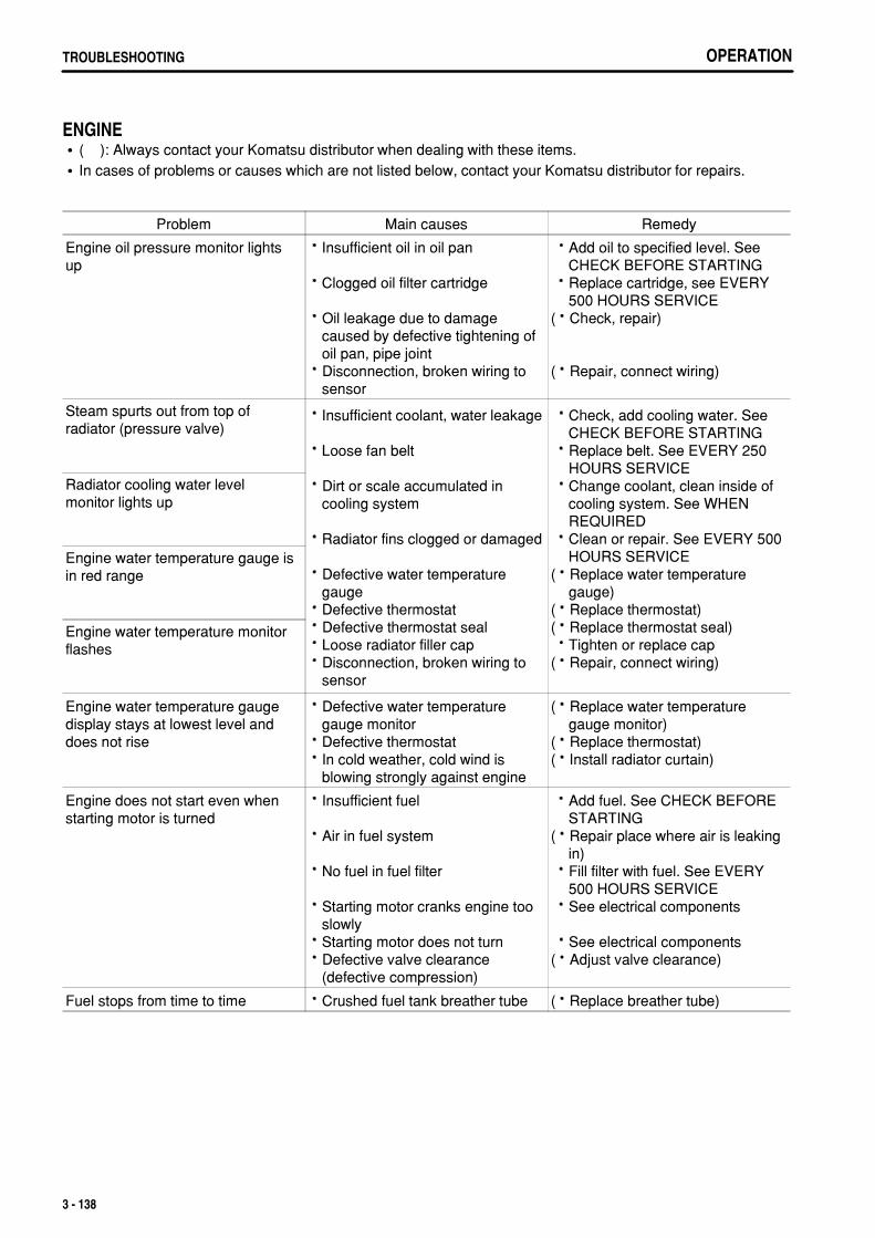
.
OPERATIONTROUBLESHOOTING
ENGINE( ): Always contact your Komatsu distributor when dealing with these items.In cases of problems or causes which are not listed below, contact your Komatsu distributor for repairs.
Problem Main causes Remedy
Engine oil pressure monitor lightsup
Insufficient oil in oil pan
Clogged oil filter cartridge
Oil leakage due to damagecaused by defective tightening ofoil pan, pipe jointDisconnection, broken wiring tosensor
Add oil to specified level. See CHECK BEFORE STARTING
Replace cartridge, see EVERY 500 HOURS SERVICE
( Check, repair)
( Repair, connect wiring)
Steam spurts out from top ofradiator (pressure valve)
Insufficient coolant, water leakage
Loose fan belt
Dirt or scale accumulated incooling system
Radiator fins clogged or damaged
Defective water temperaturegaugeDefective thermostatDefective thermostat sealLoose radiator filler capDisconnection, broken wiring tosensor
Check, add cooling water. See CHECK BEFORE STARTING
Replace belt. See EVERY 250 HOURS SERVICE
Change coolant, clean inside of cooling system. See WHEN REQUIRED
Clean or repair. See EVERY 500 HOURS SERVICE
( Replace water temperature gauge)
( Replace thermostat)( Replace thermostat seal) Tighten or replace cap( Repair, connect wiring)
Radiator cooling water levelmonitor lights up
Engine water temperature gauge isin red range
Engine water temperature monitorflashes
Engine water temperature gaugedisplay stays at lowest level anddoes not rise
Defective water temperaturegauge monitorDefective thermostatIn cold weather, cold wind isblowing strongly against engine
( Replace water temperature gauge monitor)
( Replace thermostat)( Install radiator curtain)
Engine does not start even whenstarting motor is turned
Insufficient fuel
Air in fuel system
No fuel in fuel filter
Starting motor cranks engine tooslowlyStarting motor does not turnDefective valve clearance(defective compression)
Add fuel. See CHECK BEFORE STARTING
( Repair place where air is leaking in)
Fill filter with fuel. See EVERY 500 HOURS SERVICE
See electrical components
See electrical components( Adjust valve clearance)
Fuel stops from time to time Crushed fuel tank breather tube ( Replace breather tube)
3 - 138
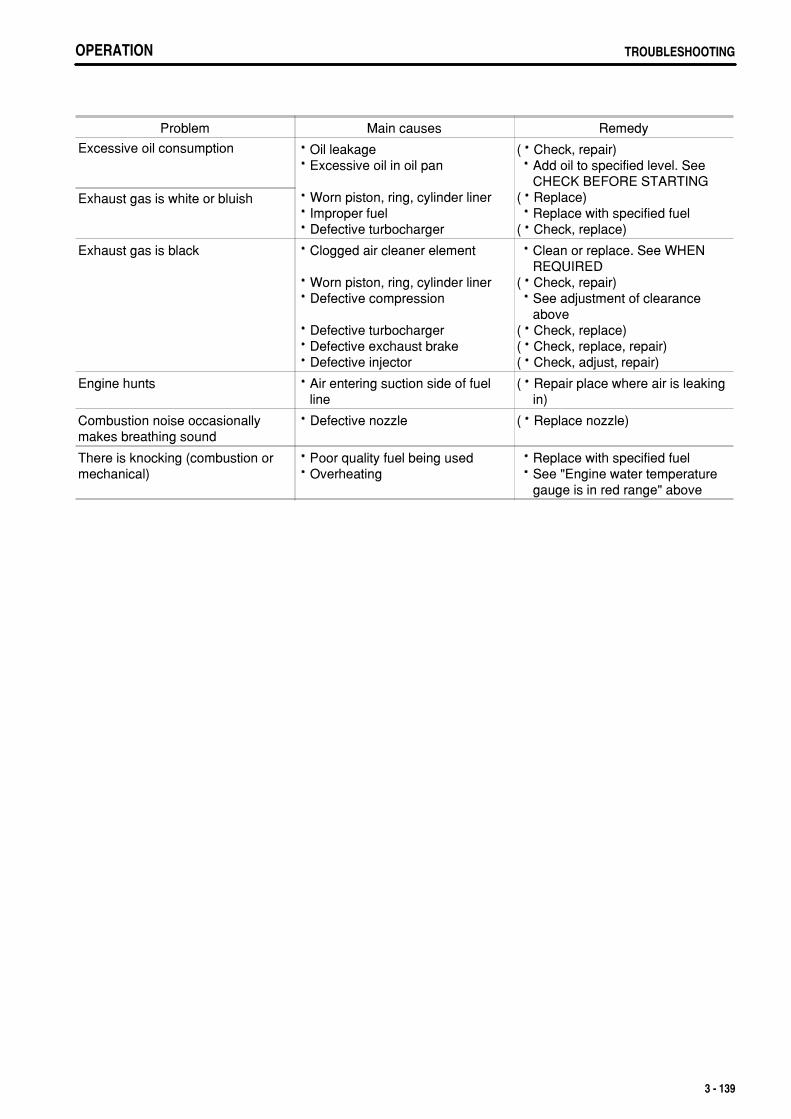
.
OPERATION TROUBLESHOOTINGOPERATION TROUBLESHOOTING
Problem Main causes Remedy
Excessive oil consumption Oil leakageExcessive oil in oil pan
Worn piston, ring, cylinder linerImproper fuelDefective turbocharger
( Check, repair) Add oil to specified level. See
CHECK BEFORE STARTING( Replace) Replace with specified fuel( Check, replace)
Exhaust gas is white or bluish
Exhaust gas is black Clogged air cleaner element
Worn piston, ring, cylinder linerDefective compression
Defective turbochargerDefective exchaust brakeDefective injector
Clean or replace. See WHEN REQUIRED
( Check, repair) See adjustment of clearance
above( Check, replace)( Check, replace, repair)( Check, adjust, repair)
Engine hunts Air entering suction side of fuelline
( Repair place where air is leaking in)
Combustion noise occasionallymakes breathing sound
Defective nozzle ( Replace nozzle)
There is knocking (combustion ormechanical)
Poor quality fuel being usedOverheating
Replace with specified fuel See "Engine water temperature
gauge is in red range" above
3 - 139
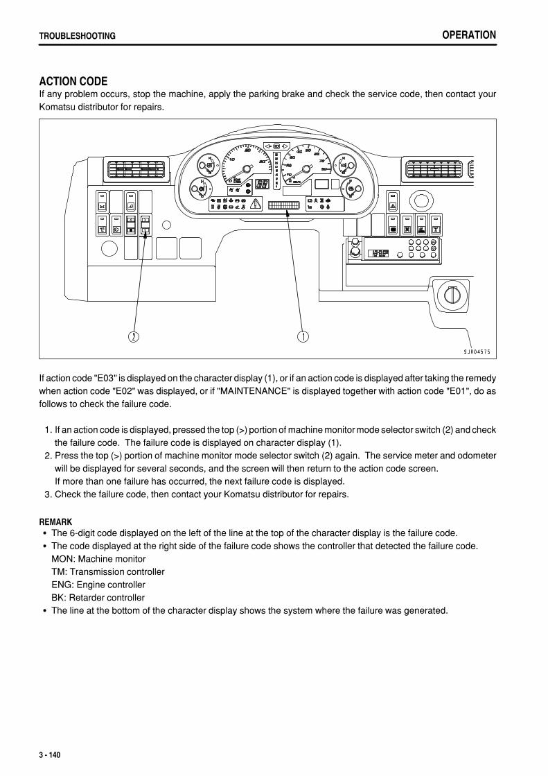
.
OPERATIONTROUBLESHOOTING
ACTION CODEIf any problem occurs, stop the machine, apply the parking brake and check the service code, then contact yourKomatsu distributor for repairs.
If action code "E03" is displayed on the character display (1), or if an action code is displayed after taking the remedywhen action code "E02" was displayed, or if "MAINTENANCE" is displayed together with action code "E01", do asfollows to check the failure code.
1. If an action code is displayed, pressed the top (>) portion of machine monitor mode selector switch (2) and checkthe failure code. The failure code is displayed on character display (1).
2. Press the top (>) portion of machine monitor mode selector switch (2) again. The service meter and odometerwill be displayed for several seconds, and the screen will then return to the action code screen.If more than one failure has occurred, the next failure code is displayed.
3. Check the failure code, then contact your Komatsu distributor for repairs.
REMARKThe 6-digit code displayed on the left of the line at the top of the character display is the failure code.The code displayed at the right side of the failure code shows the controller that detected the failure code.MON: Machine monitorTM: Transmission controllerENG: Engine controllerBK: Retarder controllerThe line at the bottom of the character display shows the system where the failure was generated.
3 - 140

.
4 - 1
.
MAINTENANCEGUIDES TO MAINTENANCE
GUIDES TO MAINTENANCEDo not perform any inspection and maintenance operation that is not found in this manual.
CHECK SERVICE METER:Check the service meter reading every day to see if the time has come for any necessary maintenance to beperformed.
KOMATSU GENUINE REPLACEMENT PARTS:Use Komatsu genuine parts specified in the Parts Book as replacement parts.
KOMATSU GENUINE OILS:For lubrication of the machine, use the Komatsu genuine lubricants. Moreover use oil of the specified viscosityaccording to the ambient temperature.
ALWAYS USE CLEAN WASHER FLUID:Use automobile window washer fluid, and be careful not to let any dirt get into it.
ALWAYS USE CLEAN OIL AND GREASE:Use clean oil and grease. Also, keep the containers of the oil and grease clean. Keep foreign materials away fromoil and grease.
CHECKING FOREIGN MATERIALS IN DRAINED OIL AND ON FILTERS:After changing the oil or replacing the filter, check the drained oil and filter for metal particles and foreign materials.If large quantities of metal particles or foreign materials are found, always report to the person in charge and carryout suitable action. In addition, when replacing the engine oil filter, fill the new filter with the specified clean oil, theninstall it.
OIL CHANGE:If your machine is equipped with a fuel strainer, do not remove it while fueling.
WELDING INSTRUCTIONS:Turn off the engine starting switch.Do not apply more than 200 V continuously.Connect grounding the cable within 1 m (3.28 ft) from the area to be welded. Connecting grounding cable nearmeters and connectors will lead to the failure of meters.If a seal or bearing happens to come between the part being welded and grounding point, change the groundingpoint to avoid such parts.Do not use the area around the pins or the hydraulic cylinders as the grounding point.Sparks will cause damage to the plated portion.
DO NOT DROP THINGS INSIDE MACHINE:When opening inspection windows or the oil filler port of the tank to carry out inspection, be careful not to dropnuts, bolts, or tools inside the machine.If such things are dropped inside the machine, it may cause damage and/or malfunction of the machine, and willlead to failure. If you drop anything inside the machine, always remove it immediately.Do not put unnecessary things in your pockets. Carry only things which are necessary for inspection.
4 - 2
.
MAINTENANCE GUIDES TO MAINTENANCE
DUSTY WORKSITES:When working at dusty worksites, do as follows:
Inspect the dust indicator frequently to see if the air cleaner is clogged.Clean the air cleaner element at a shorter interval than specified.Clean the radiator core frequently to avoid clogging.Clean and replace the fuel filter frequently.Clean electrical components, especially the starting motor and alternator, to avoid accumulation of dust.When inspecting or changing the oil, move the machine to a place that is free of dust to prevent dirt from gettinginto the oil.
AVOID MIXING OILS:If a different brand or grade of oil has to be added, drain the old oil and replace all the oil with the new brand or gradeof oil. Never mix different brand or grade of oil.
LOCKING INSPECTION COVERS:Lock inspection cover securely into position with the lock bar. If inspection or maintenance is performed withinspection cover not locked in position, there is a danger that it may be suddenly blow shut by the wind and causeinjury to the worker.
BLEEDING AIR FROM HYDRAULIC CIRCUIT:If the hydraulic components have been repaired or replaced and if the hydraulic hoses, pipes, etc. have beendisconnected, it is necessary to bleed air in the circuit. See "WHEN REQUIRED (PAGE 4-20)".
PRECAUTIONS WHEN INSTALLING HYDRAULIC HOSES:When removing parts at locations where there are O-rings or gasket seals, clean the mounting surface, andreplace with new parts.When doing this, be careful not to forget to assemble the O-rings and gaskets.When installing the hoses, do not twist them or bend them sharply. If they are installed so, their service life willbe shortened extremely and they may be damaged.
CHECKS AFTER INSPECTION AND MAINTENANCE:If you forget to perform the checks after inspection and maintenance, unexpected problems may occur, and this maylead to serious injury or property damage. Always do the following:
Checks after operation (with engine stopped)Have any inspection and maintenance points been forgotten?Have all inspection and maintenance items been performed correctly?Have any tools or parts been dropped inside the machine? It is particularly dangerous if parts are droppedinside the machine and get caught in the lever linkage mechanism.Are there any leakage of coolant or oil? Have all nuts and bolts been tightened?
Check when the engine is runningSee "TWO WORKERS FOR MAINTENANCE WHEN ENGINE IS RUNNING (PAGE 2-32)" in the section onsafety for checking when the engine is running. Pay enough attention for safety.Check if the inspected and serviced area is normally operated.Increase the engine speed to check for the leak of fuel and oil.
4 - 3
.
MAINTENANCEOUTLINE OF SERVICE
OUTLINE OF SERVICEAlways use Komatsu genuine parts for replacement parts, grease or oil.When changing the oil or adding oil, do not mix different types of oil. When changing the type of oil, drain all theold oil and fill completely with the new oil. Always replace the filter at the same time. (There is no problem if thesmall amount of oil remaining in the piping mixes with the new oil.)Unless otherwise specified, when the machine is shipped from the factory, it is filled with the oil and coolant listedin the table below.
Item Type
Engine oil pan Engine oil EO15W40DH (Komatsu genuine parts)
Transmission case(incl. brake oil tank)
Power train oil TO10 (Komatsu genuine parts)
Hydraulic tank Power train oil TO10 (Komatsu genuine parts)
Front suspensionRear suspension
Hydraulic oil HO-MVK (Komatsu genuine parts)
Front differential caseCenter differential caseRear differential caseFront final drive caseCenter final drive caseRear final drive case
Axle oil AXO80 (Komatsu genuine parts)
Radiator Supercoolant AF-NAC (Density:30% or above)(Komatsu genuine parts)
HANDLING OIL, FUEL, COOLANT, AND PERFORMING OIL CLINIC
OILOil is used in the engine and hydraulic equipment under extremely severe conditions (high temperature, highpressure), and deteriorates with use.Always use oil that matches the grade and maximum and minimum ambient temperatures recommended in theOperation and Maintenance Manual. Even if the oil is not dirty, always change the oil at the specified interval.Oil corresponds to blood in the human body, always be careful when handling it to prevent any impurities (water,metal particles, dirt, etc.) from getting in.The majority of problems with the machine are caused by the entry of such impurities.Take particular care not to let any impurities get in when storing or adding oil.Never mix oils of different grades or brands.Always add the specified amount of oil.Having too much oil or too little oil are both causes of problems.If the oil in the work equipment is not clear, there is probably water or air getting into the circuit. In such cases,please contact your Komatsu distributor.When changing the oil, always replace the related filters at the same time.We recommend you have an analysis made of the oil periodically to check the condition of the machine. Forthose who wish to use this service, please contact your Komatsu distributor.When using commercially available oil, it may be necessary to reduce the oil change interval.We recommend that you use the Komatsu oil clinic to carry out a detailed checks of the characteristics of the oil.
4 - 4
.
MAINTENANCE OUTLINE OF SERVICE
FUELTo prevent the moisture in the air from condensing and forming water inside the fuel tank, always fill the fuel tankafter completing the day's work.The fuel pump is a precision instrument, and if fuel containing water or dirt is used, it cannot work properly.Be extremely careful not to let impurities get in when storing or adding fuel.Always use the fuel specified for the temperature in the Operation and Maintenance Manual.
If the fuel is used at temperatures lower than the specified temperature (particularly at temperatures below -15°C (5°F), the fuel will solidify.If the fuel is used at temperatures higher than the specified temperature, the viscosity will drop, and this mayresult in problems such as a drop in output.
Before starting the engine, or when 10 minutes have passed after adding fuel, drain the sediment and water fromthe fuel tank.If the engine runs out of fuel, or if the filters have been replaced, it is necessary to bleed the air from the circuit.If there is any foreign material in the fuel tank, wash the tank and fuel system.
NOTICEAlways use diesel fuel. Never use any other fuel.The engine on this machine uses electronic control and high-pressure fuel injection equipment to enable it to provide good fuelconsumption and good exhaust gas characteristics. For this reason, high-precision parts and lubricating ability are demanded.Using low-viscosity fuel with poor lubricating ability will cause a marked reduction in the durability of the engine.
COOLANT AND WATER FOR DILUTIONThe coolant has the important function of preventing corrosion as well as preventing freezing.Even in the areas where freezing is not an issue, the use of antifreeze coolant is essential.Komatsu machines are supplied with Komatsu Supercoolant (AF-NAC). Komatsu Supercoolant (AF-NAC) hasexcellent anticorrosion, antifreeze and cooling properties and can be used continuously for 2 years or 4000 hours.Komatsu Supercoolant (AF-NAC) is strongly recommended wherever available.When using Komatsu Supercoolant (AF-NAC), there is no need to use a corrosion resistor. For details, see"CLEAN INSIDE OF COOLING SYSTEM (PAGE 4-26)".When diluting the antifreeze coolant, use distilled water or tap water (soft water).Natural water, such as a river water or well water (hard water), contains large amounts of minerals (calcium,magnesium, etc.), and this makes it easier for scale to form inside the engine or radiator. Once scale is depositedinside the engine or radiator, it is extremely difficult to remove. It also causes overheating due to poor heatexchange, so when you dilute the coolant, we recommend that you use water with an overall hardness of lessthan 100 PPM.When using antifreeze, always observe the precautions given in the Operation and Maintenance Manual.Antifreeze coolant is flammable, so be sure to keep it away from flame.The ratio of Supercoolant (AF-NAC) to water differs according to the ambient temperature.For details of the ratio when mixing, see "CLEAN INSIDE OF COOLING SYSTEM (PAGE 4-26)".Supercoolant (AF-NAC) may be supplied already mixed. In such cases, never dilute with water.If the engine overheats, wait for the engine to cool before adding coolant.If the coolant level is low, it will cause overheating, and will also cause problems with corrosion due to air enteringthe coolant.
4 - 5

.
MAINTENANCEOUTLINE OF SERVICE
GREASEGrease is used to prevent seizure and noises at the joints.This construction equipment is used under heavy-duty conditions. Always use the recommended grease andfollow the change intervals and recommended ambient temperatures given in this Operation and MaintenanceManual.The nipples not included in the maintenance section are nipples for overhaul, so they do not need grease.If any part becomes stiff after being used for long time, add grease.Always wipe off all of the old grease that is pushed out when greasing.Be particularly careful to wipe off the old grease in places where sand or dirt sticking in the grease would causewear of the rotating parts.
4 - 6
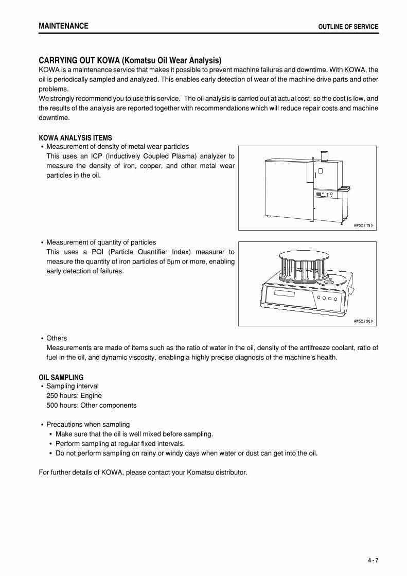
.
MAINTENANCE OUTLINE OF SERVICE
CARRYING OUT KOWA (Komatsu Oil Wear Analysis)KOWA is a maintenance service that makes it possible to prevent machine failures and downtime. With KOWA, theoil is periodically sampled and analyzed. This enables early detection of wear of the machine drive parts and otherproblems.We strongly recommend you to use this service. The oil analysis is carried out at actual cost, so the cost is low, andthe results of the analysis are reported together with recommendations which will reduce repair costs and machinedowntime.
KOWA ANALYSIS ITEMSMeasurement of density of metal wear particlesThis uses an ICP (Inductively Coupled Plasma) analyzer tomeasure the density of iron, copper, and other metal wearparticles in the oil.
Measurement of quantity of particlesThis uses a PQI (Particle Quantifier Index) measurer tomeasure the quantity of iron particles of 5µm or more, enablingearly detection of failures.
OthersMeasurements are made of items such as the ratio of water in the oil, density of the antifreeze coolant, ratio offuel in the oil, and dynamic viscosity, enabling a highly precise diagnosis of the machine's health.
OIL SAMPLINGSampling interval250 hours: Engine500 hours: Other components
Precautions when samplingMake sure that the oil is well mixed before sampling.Perform sampling at regular fixed intervals.Do not perform sampling on rainy or windy days when water or dust can get into the oil.
For further details of KOWA, please contact your Komatsu distributor.
4 - 7
.
MAINTENANCEOUTLINE OF SERVICE
STORING OIL AND FUELKeep indoors to prevent any water, dirt, or other impurities from getting in.When keeping drum cans for a long period, put the drum on its side so that the filler port of the drums is at the sideto prevent moisture from being sucked in.If drums have to be stored outside, cover them with a waterproof sheet or take other measures to protect them.To prevent any change in quality during long-term storage, be sure to use in the order of first in - first out (use theoldest oil or fuel first).
FILTERSFilters are extremely important safety parts. They prevent impurities in the fuel and air circuits from enteringimportant equipment and causing problems.Replace all filters periodically. For details, see the Operation and Maintenance Manual.However, when working in severe conditions, replace the filters at shorter intervals according to the oil and fuel(sulfur content) being used.Never try to clean the filters (cartridge type) and use them again. Always replace with new filters.When replacing oil filters, check if any metal particles are attached to the old filter. If any metal particles are found,contact your Komatsu distributor.When replacing the engine oil filter, fill the new filter with the specified clean oil, then install it.Do not open packs of spare filters until just before they are to be used.Always use Komatsu genuine filters.
OUTLINE OF ELECTRIC SYSTEMIt is extremely dangerous if the electrical equipment becomes wet or the covering of the wiring is damaged. Thiswill cause an electrical short circuit and may lead to malfunction of the machine. Do not wash the inside of theoperator's cab with water. When washing the machine, be careful not to let water get into the electricalcomponents.Service relating to the electric system is checking fan belt tension, checking damage or wear to the fan belt andchecking battery fluid level.Never install any electric components other than those specified by Komatsu.External electro-magnetic interference may cause malfunction of the control system controller, before installinga radio receiver or other wireless equipment, contact your Komatsu distributor.When working at the seashore, carefully clean the electric system to prevent corrosion.When installing an operator's cab cooler or any other electrical equipment, connect it to an independent powersource connector. The cables to supply power to the optional equipment must never be connected to the fuse,starting switch, or battery relay.
4 - 8

.
MAINTENANCE WEAR PARTS
WEAR PARTSWear parts such as the filter element, air cleaner element, etc. are to be replaced at the time of periodic maintenanceor before their abrasion limits.The wear parts should be changed correctly in order to use the machine economically.For part change, Komatsu genuine parts of excellent quality should be used.When ordering parts, please check the part number in the parts book.
WEAR PARTS LISTThe parts in parentheses are to be replaced at the same time.
Item Part No. Part Name Q'ty Replacement frequency
Engine oil filter 600-211-1340 Cartridge 1EVERY 500 HOURS
Fuel prefilter 600-319-3440 Cartridge 1
Fuel main filter 600-319-3520 Cartridge 1
EVERY 1000 HOURS
Corrosion resistor 600-411-1151 Cartridge 1
Transmission oil filter(Valve side)
714-07-28712 Cartridge 1
Transmission oil filter(Brake cooling side)
07063-51210(07000-F5180)
Element(O-ring)
1(1)
Brake oil filter569-43-83920(07000-12065)(07001-02065)
Element(O-ring)
(Back-up ring)
1(1)(1)
Hydraulic filter07063-51142
(07000-F5180)Element(O-ring)
1(1)
EVERY 2000 HOURS
Air cleaner600-185-6100 Element Ass'y 1 -
600-185-6110 Outer element 1 -
4 - 9
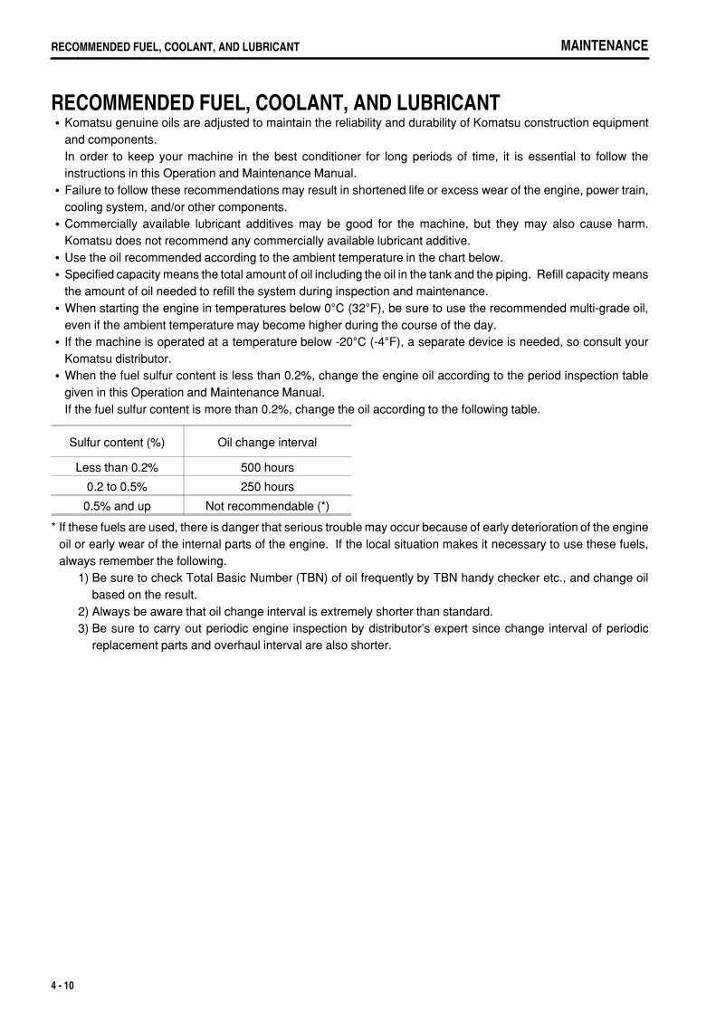
.
MAINTENANCERECOMMENDED FUEL, COOLANT, AND LUBRICANT
RECOMMENDED FUEL, COOLANT, AND LUBRICANTKomatsu genuine oils are adjusted to maintain the reliability and durability of Komatsu construction equipmentand components.In order to keep your machine in the best conditioner for long periods of time, it is essential to follow theinstructions in this Operation and Maintenance Manual.Failure to follow these recommendations may result in shortened life or excess wear of the engine, power train,cooling system, and/or other components.Commercially available lubricant additives may be good for the machine, but they may also cause harm.Komatsu does not recommend any commercially available lubricant additive.Use the oil recommended according to the ambient temperature in the chart below.Specified capacity means the total amount of oil including the oil in the tank and the piping. Refill capacity meansthe amount of oil needed to refill the system during inspection and maintenance.When starting the engine in temperatures below 0°C (32°F), be sure to use the recommended multi-grade oil,even if the ambient temperature may become higher during the course of the day.If the machine is operated at a temperature below -20°C (-4°F), a separate device is needed, so consult yourKomatsu distributor.When the fuel sulfur content is less than 0.2%, change the engine oil according to the period inspection tablegiven in this Operation and Maintenance Manual.If the fuel sulfur content is more than 0.2%, change the oil according to the following table.
Sulfur content (%) Oil change interval
Less than 0.2% 500 hours
0.2 to 0.5% 250 hours
0.5% and up Not recommendable (*)
* If these fuels are used, there is danger that serious trouble may occur because of early deterioration of the engineoil or early wear of the internal parts of the engine. If the local situation makes it necessary to use these fuels,always remember the following.
1) Be sure to check Total Basic Number (TBN) of oil frequently by TBN handy checker etc., and change oilbased on the result.
2) Always be aware that oil change interval is extremely shorter than standard. 3) Be sure to carry out periodic engine inspection by distributor's expert since change interval of periodic
replacement parts and overhaul interval are also shorter.
4 - 10
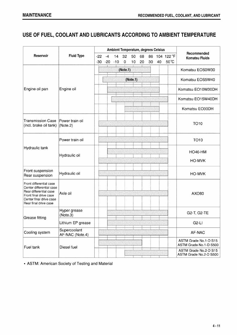
.
MAINTENANCE RECOMMENDED FUEL, COOLANT, AND LUBRICANT
USE OF FUEL, COOLANT AND LUBRICANTS ACCORDING TO AMBIENT TEMPERATURE
ASTM: American Society of Testing and Material
4 - 11
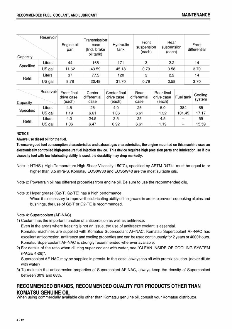
.
MAINTENANCERECOMMENDED FUEL, COOLANT, AND LUBRICANT MAINTENANCERECOMMENDED FUEL, COOLANT, AND LUBRICANT
Reservoir
Capacity
Engine oilpan
Transmission case
(Incl. brakeoil tank)
Hydraulictank
Frontsuspension
(each)
Rearsuspension
(each)
Frontdifferential
SpecifiedLiters 44 165 171 3 2.2 14
US gal 11.62 43.59 45.18 0.79 0.58 3.70
RefillLiters 37 77.5 120 3 2.2 14
US gal 9.78 20.48 31.70 0.79 0.58 3.70
Reservoir
Capacity
Front finaldrive case�
(each)
Centerdifferential
case
Center finaldrive case�
(each)
Reardifferential
case
Rear finaldrive case�
(each)Fuel tank Cooling
system
SpecifiedLiters 4.5 25 4.0 25 5.0 384 65
US gal 1.19 6.61 1.06 6.61 1.32 101.45 17.17
RefillLiters 4.0 24.5 3.5 25 4.5 – 59
US gal 1.06 6.47 0.92 6.61 1.19 – 15.59
NOTICEAlways use diesel oil for the fuel.To ensure good fuel consumption characteristics and exhaust gas characteristics, the engine mounted on this machine uses anelectronically controlled high-pressure fuel injection device. This device requires high precision parts and lubrication, so if lowviscosity fuel with low lubricating ability is used, the durability may drop markedly.
Note 1: HTHS ( High-Temperature High-Shear Viscosity 150°C), specified by ASTM D4741 must be equal to orhigher than 3.5 mPa-S. Komatsu EOS0W30 and EOS5W40 are the most suitable oils.
Note 2: Powertrain oil has different properties from engine oil. Be sure to use the recommended oils.
Note 3: Hyper grease (G2-T, G2-TE) has a high performance.When it is necessary to improve the lubricating ability of the grease in order to prevent squeaking of pins andbushings, the use of G2-T or G2-TE is recommended.
Note 4: Supercoolant (AF-NAC)1) Coolant has the important function of anticorrosion as well as antifreeze.
Even in the areas where freezing is not an issue, the use of antifreeze coolant is essential.Komatsu machines are supplied with Komatsu Supercoolant AF-NAC. Komatsu Supercoolant AF-NAC hasexcellent anticorrosion, antifreeze and cooling properties and can be used continuously for 2 years or 4000 hours.Komatsu Supercoolant AF-NAC is strongly recommended wherever available.
2) For details of the ratio when diluting super coolant with water, see "CLEAN INSIDE OF COOLING SYSTEM(PAGE 4-26)".Supercoolant AF-NAC may be supplied in premix. In this case, always top off with premix solution. (never dilutewith water)
3) To maintain the anticorrosion properties of Supercoolant AF-NAC, always keep the density of Supercoolantbetween 30% and 68%.
RECOMMENDED BRANDS, RECOMMENDED QUALITY FOR PRODUCTS OTHER THAN KOMATSU GENUINE OILWhen using commercially available oils other than Komatsu genuine oil, consult your Komatsu distributor.
4 - 12
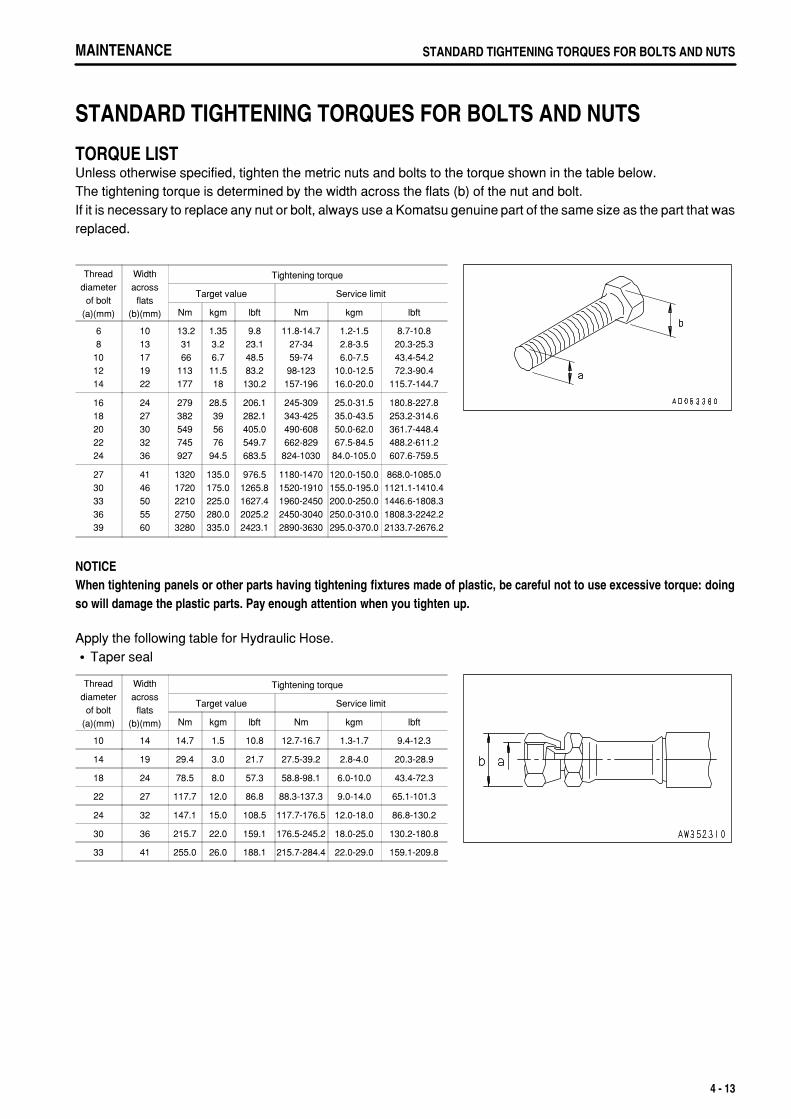
.
MAINTENANCE STANDARD TIGHTENING TORQUES FOR BOLTS AND NUTS
STANDARD TIGHTENING TORQUES FOR BOLTS AND NUTS
TORQUE LISTUnless otherwise specified, tighten the metric nuts and bolts to the torque shown in the table below.The tightening torque is determined by the width across the flats (b) of the nut and bolt.If it is necessary to replace any nut or bolt, always use a Komatsu genuine part of the same size as the part that wasreplaced.
Threaddiameter
of bolt(a)(mm)
Widthacross
flats(b)(mm)
Tightening torque
Target value Service limit
Nm kgm lbft Nm kgm lbft
68
101214
1013171922
13.2 31 66113177
1.353.26.711.518
9.823.148.583.2130.2
11.8-14.727-3459-7498-123157-196
1.2-1.52.8-3.56.0-7.5
10.0-12.516.0-20.0
8.7-10.820.3-25.343.4-54.272.3-90.4
115.7-144.7
1618202224
2427303236
279382549745927
28.5395676
94.5
206.1282.1405.0549.7683.5
245-309343-425490-608662-829
824-1030
25.0-31.535.0-43.550.0-62.067.5-84.584.0-105.0
180.8-227.8253.2-314.6361.7-448.4488.2-611.2607.6-759.5
2730333639
4146505560
13201720221027503280
135.0175.0225.0280.0335.0
976.51265.81627.42025.22423.1
1180-14701520-19101960-24502450-30402890-3630
120.0-150.0155.0-195.0200.0-250.0250.0-310.0295.0-370.0
868.0-1085.01121.1-1410.41446.6-1808.31808.3-2242.22133.7-2676.2
NOTICEWhen tightening panels or other parts having tightening fixtures made of plastic, be careful not to use excessive torque: doingso will damage the plastic parts. Pay enough attention when you tighten up.
Apply the following table for Hydraulic Hose.Taper seal
Threaddiameter
of bolt(a)(mm)
Widthacross
flats(b)(mm)
Tightening torque
Target value Service limit
Nm kgm lbft Nm kgm lbft
10 14 14.7 1.5 10.8 12.7-16.7 1.3-1.7 9.4-12.3
14 19 29.4 3.0 21.7 27.5-39.2 2.8-4.0 20.3-28.9
18 24 78.5 8.0 57.3 58.8-98.1 6.0-10.0 43.4-72.3
22 27 117.7 12.0 86.8 88.3-137.3 9.0-14.0 65.1-101.3
24 32 147.1 15.0 108.5 117.7-176.5 12.0-18.0 86.8-130.2
30 36 215.7 22.0 159.1 176.5-245.2 18.0-25.0 130.2-180.8
33 41 255.0 26.0 188.1 215.7-284.4 22.0-29.0 159.1-209.8
4 - 13
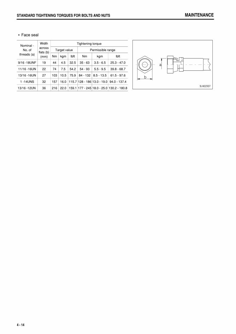
.
MAINTENANCESTANDARD TIGHTENING TORQUES FOR BOLTS AND NUTS
Face seal
Nominal -No. of
threads (a)
Widthacrossflats (b)(mm)
Tightening torque
Target value Permissible range
Nm kgm lbft Nm kgm lbft
9/16 -18UNF 19 44 4.5 32.5 35 - 63 3.5 - 6.5 25.3 - 47.0
11/16 -16UN 22 74 7.5 54.2 54 - 93 5.5 - 9.5 39.8 - 68.7
13/16 -16UN 27 103 10.5 75.9 84 - 132 8.5 - 13.5 61.5 - 97.6
1 -14UNS 32 157 16.0 115.7 128 - 186 13.0 - 19.0 94.0 - 137.4
13/16 -12UN 36 216 22.0 159.1 177 - 245 18.0 - 25.0 130.2 - 180.8
4 - 14

.
MAINTENANCE PERIODIC REPLACEMENT OF SAFETY CRITICAL PARTS
PERIODIC REPLACEMENT OF SAFETY CRITICAL PARTSTo ensure safety at all times when operating or driving the machine, the user of the machine must always carry outperiodic maintenance. In addition, to further improve safety, the parts in the safety-critical parts list on the next pagemust also be replaced at the specified interval. These parts are particularly closely connected to safety and fireprevention, so please contact your Komatsu distributor to have them replaced.Material quality of these parts can change as time passes and they are likely to wear out or deteriorate. However,it is difficult to determine the extent of wear or deterioration at the time of periodic maintenance. Hence, it is requiredto replace them with new ones regardless of their condition after a certain period of usage. This is important toensure that these parts maintain their full performance at all times.Furthermore, should anything abnormal be found on any of these parts, replace it with a new one even if the periodicreplacement time for the part has not yet arrived.If any of the hose clamps show deterioration like deformation or cracking, replace the clamps at the same time asthe hoses.Also perform the following checks with hydraulic hoses which need to be replaced periodically. Tighten all looseclamps and replace defective hoses, as required.When replacing hoses, always replace O-rings, gaskets, and other such parts at the same time.
4 - 15
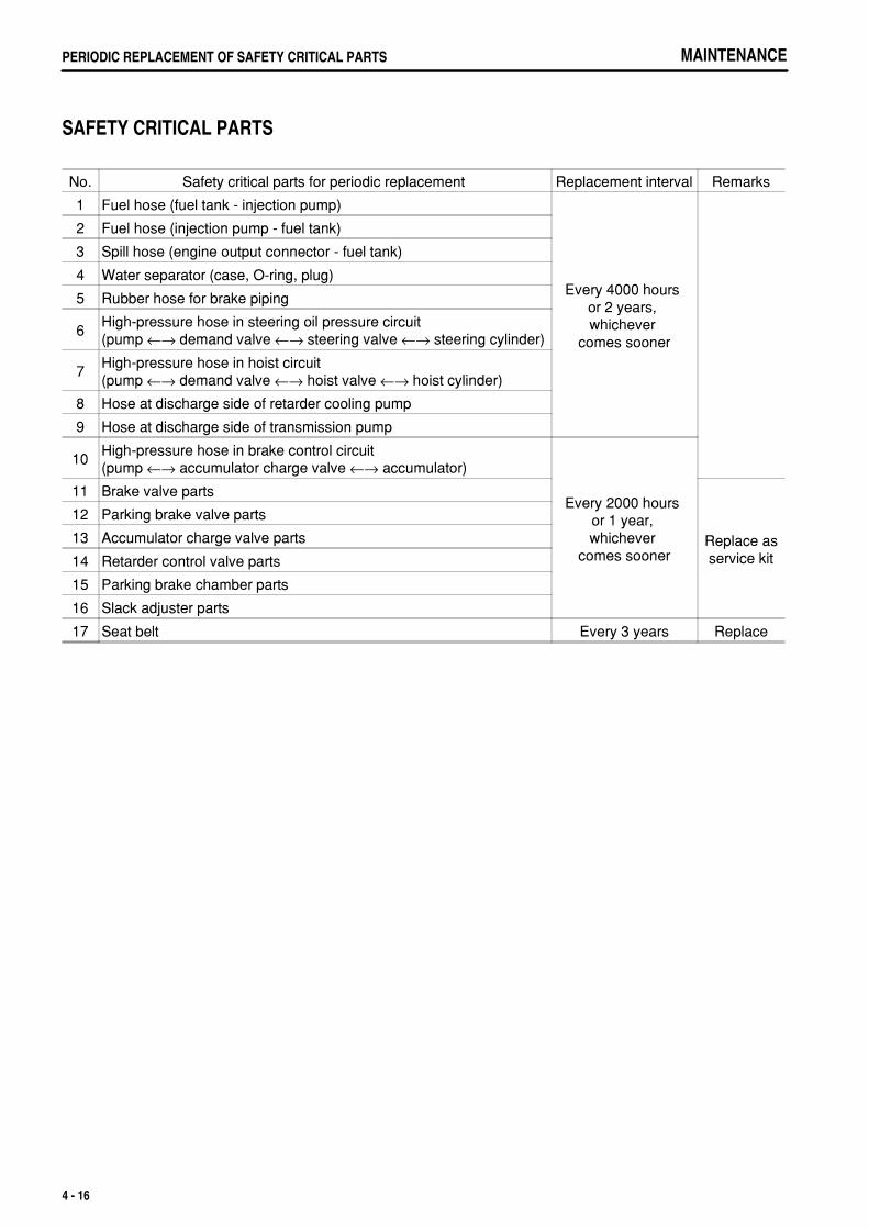
.
MAINTENANCEPERIODIC REPLACEMENT OF SAFETY CRITICAL PARTS
SAFETY CRITICAL PARTS
No. Safety critical parts for periodic replacement Replacement interval Remarks
1 Fuel hose (fuel tank - injection pump)
Every 4000 hours or 2 years, whichever
comes sooner
2 Fuel hose (injection pump - fuel tank)
3 Spill hose (engine output connector - fuel tank)
4 Water separator (case, O-ring, plug)
5 Rubber hose for brake piping
6High-pressure hose in steering oil pressure circuit(pump ←→ demand valve ←→ steering valve ←→ steering cylinder)
7High-pressure hose in hoist circuit(pump ←→ demand valve ←→ hoist valve ←→ hoist cylinder)
8 Hose at discharge side of retarder cooling pump
9 Hose at discharge side of transmission pump
10High-pressure hose in brake control circuit(pump ←→ accumulator charge valve ←→ accumulator)
Every 2000 hours or 1 year, whichever
comes sooner
11 Brake valve parts
Replace asservice kit
12 Parking brake valve parts
13 Accumulator charge valve parts
14 Retarder control valve parts
15 Parking brake chamber parts
16 Slack adjuster parts
17 Seat belt Every 3 years Replace
4 - 16
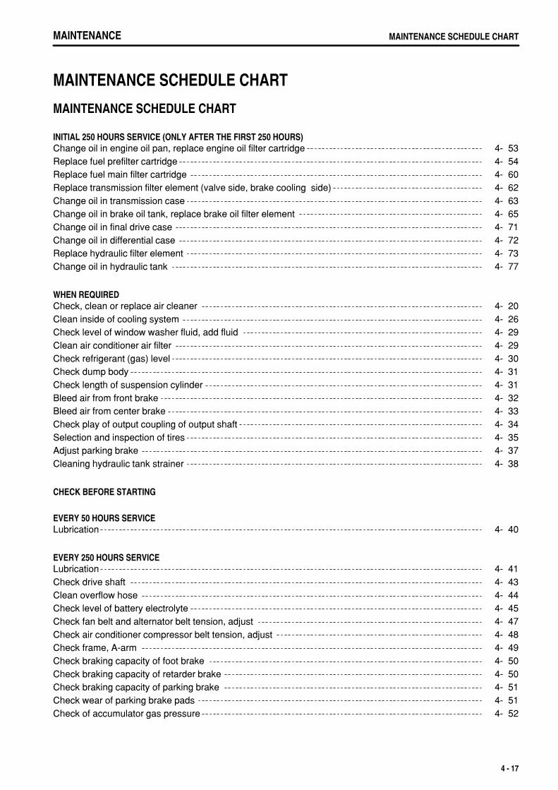
.
MAINTENANCE MAINTENANCE SCHEDULE CHART
MAINTENANCE SCHEDULE CHART
MAINTENANCE SCHEDULE CHART
INITIAL 250 HOURS SERVICE (ONLY AFTER THE FIRST 250 HOURS)Change oil in engine oil pan, replace engine oil filter cartridge 4- 53Replace fuel prefilter cartridge 4- 54Replace fuel main filter cartridge 4- 60Replace transmission filter element (valve side, brake cooling side) 4- 62Change oil in transmission case 4- 63Change oil in brake oil tank, replace brake oil filter element 4- 65Change oil in final drive case 4- 71Change oil in differential case 4- 72Replace hydraulic filter element 4- 73Change oil in hydraulic tank 4- 77
WHEN REQUIREDCheck, clean or replace air cleaner 4- 20Clean inside of cooling system 4- 26Check level of window washer fluid, add fluid 4- 29Clean air conditioner air filter 4- 29Check refrigerant (gas) level 4- 30Check dump body 4- 31Check length of suspension cylinder 4- 31Bleed air from front brake 4- 32Bleed air from center brake 4- 33Check play of output coupling of output shaft 4- 34Selection and inspection of tires 4- 35Adjust parking brake 4- 37Cleaning hydraulic tank strainer 4- 38
CHECK BEFORE STARTING
EVERY 50 HOURS SERVICELubrication 4- 40
EVERY 250 HOURS SERVICELubrication 4- 41Check drive shaft 4- 43Clean overflow hose 4- 44Check level of battery electrolyte 4- 45Check fan belt and alternator belt tension, adjust 4- 47Check air conditioner compressor belt tension, adjust 4- 48Check frame, A-arm 4- 49Check braking capacity of foot brake 4- 50Check braking capacity of retarder brake 4- 50Check braking capacity of parking brake 4- 51Check wear of parking brake pads 4- 51Check of accumulator gas pressure 4- 52
4 - 17
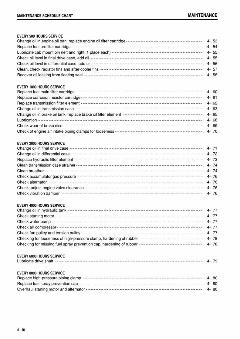
.
MAINTENANCEMAINTENANCE SCHEDULE CHART
EVERY 500 HOURS SERVICEChange oil in engine oil pan, replace engine oil filter cartridge 4- 53Replace fuel prefilter cartridge 4- 54Lubricate cab mount pin (left and right: 1 place each) 4- 55Check oil level in final drive case, add oil 4- 55Check oil level in differential case, add oil 4- 56Clean, check radiator fins and after cooler fins 4- 57Recover oil leaking from floating seal 4- 58
EVERY 1000 HOURS SERVICEReplace fuel main filter cartridge 4- 60Replace corrosion resistor cartridge 4- 61Replace transmission filter element 4- 62Change oil in transmission case 4- 63Change oil in brake oil tank, replace brake oil filter element 4- 65Lubrication 4- 68Check wear of brake disc 4- 69Check of engine air intake piping clamps for looseness 4- 70
EVERY 2000 HOURS SERVICEChange oil in final drive case 4- 71Change oil in differential case 4- 72Replace hydraulic filter element 4- 73Clean transmission case strainer 4- 74Clean breather 4- 74Check accumulator gas pressure 4- 76Check alternator 4- 76Check, adjust engine valve clearance 4- 76Check vibration damper 4- 76
EVERY 4000 HOURS SERVICEChange oil in hydraulic tank 4- 77Check starting motor 4- 77Check water pump 4- 77Check air compressor 4- 77Check fan pulley and tension pulley 4- 77Checking for looseness of high-pressure clamp, hardening of rubber 4- 78Checking for missing fuel spray prevention cap, hardening of rubber 4- 78
EVERY 6000 HOURS SERVICELubricate drive shaft 4- 79
EVERY 8000 HOURS SERVICEReplace high-pressure piping clamp 4- 80Replace fuel spray prevention cap 4- 80Overhaul starting motor and alternator 4- 80
4 - 18
.
MAINTENANCE SERVICE PROCEDURE
SERVICE PROCEDURE
INITIAL 250 HOURS SERVICE (ONLY AFTER THE FIRST 250 HOURS)Perform the following maintenance only after the first 250 hours.
Change oil in engine oil pan, replace engine oil filter cartridgeReplace fuel prefilter cartridgeReplace fuel main filter cartridgeReplace transmission filter element (valve side, brake cooling side)Change oil in transmission caseChange oil in brake oil tank, replace brake oil filter elementChange oil in final drive caseChange oil in differential caseReplace hydraulic filter elementChange oil in hydraulic tank
For details of the method of replacing or maintaining, see EVERY 500 HOURS, EVERY 1000 HOURS, EVERY2000 HOURS SERVICE and EVERY 4000 HOURS SERVICE.
4 - 19
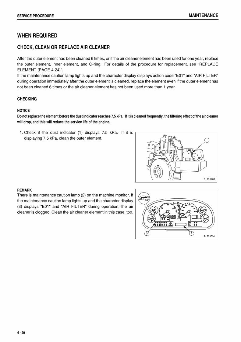
.
MAINTENANCESERVICE PROCEDURE
WHEN REQUIRED
CHECK, CLEAN OR REPLACE AIR CLEANER
After the outer element has been cleaned 6 times, or if the air cleaner element has been used for one year, replacethe outer element, inner element, and O-ring. For details of the procedure for replacement, see "REPLACEELEMENT (PAGE 4-24)".If the maintenance caution lamp lights up and the character display displays action code "E01" and "AIR FILTER"during operation immediately after the outer element is cleaned, replace the element even if the outer element hasnot been cleaned 6 times or the air cleaner element has not been used more than 1 year.
CHECKING
NOTICEDo not replace the element before the dust indicator reaches 7.5 kPa. If it is cleaned frequently, the filtering effect of the air cleanerwill drop, and this will reduce the service life of the engine.
1. Check if the dust indicator (1) displays 7.5 kPa. If it isdisplaying 7.5 kPa, clean the outer element.
REMARKThere is maintenance caution lamp (2) on the machine monitor. Ifthe maintenance caution lamp lights up and the character display(3) displays "E01" and "AIR FILTER" during operation, the aircleaner is clogged. Clean the air cleaner element in this case, too.
4 - 20
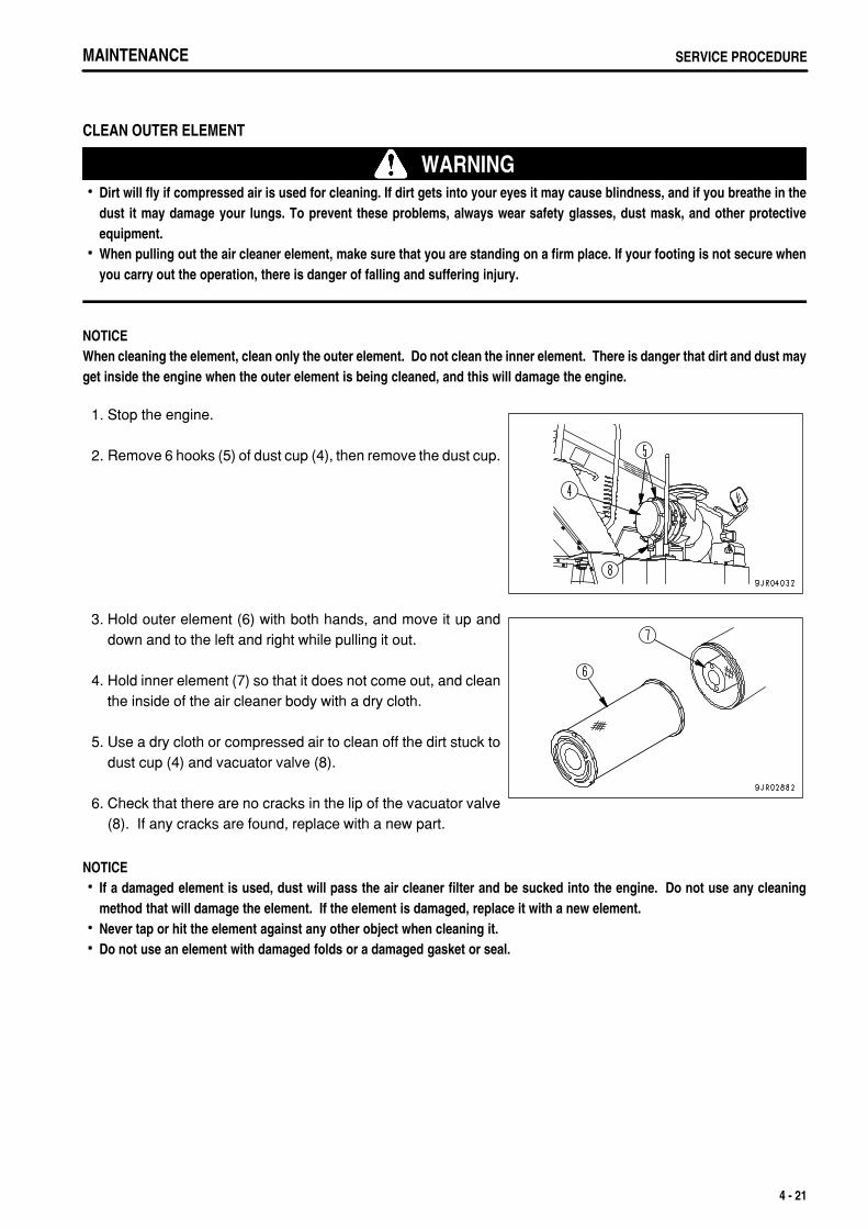
.
MAINTENANCE SERVICE PROCEDURE
CLEAN OUTER ELEMENT
WARNINGDirt will fly if compressed air is used for cleaning. If dirt gets into your eyes it may cause blindness, and if you breathe in thedust it may damage your lungs. To prevent these problems, always wear safety glasses, dust mask, and other protectiveequipment.When pulling out the air cleaner element, make sure that you are standing on a firm place. If your footing is not secure whenyou carry out the operation, there is danger of falling and suffering injury.
NOTICEWhen cleaning the element, clean only the outer element. Do not clean the inner element. There is danger that dirt and dust mayget inside the engine when the outer element is being cleaned, and this will damage the engine.
1. Stop the engine.
2. Remove 6 hooks (5) of dust cup (4), then remove the dust cup.
3. Hold outer element (6) with both hands, and move it up anddown and to the left and right while pulling it out.
4. Hold inner element (7) so that it does not come out, and cleanthe inside of the air cleaner body with a dry cloth.
5. Use a dry cloth or compressed air to clean off the dirt stuck todust cup (4) and vacuator valve (8).
6. Check that there are no cracks in the lip of the vacuator valve(8). If any cracks are found, replace with a new part.
NOTICEIf a damaged element is used, dust will pass the air cleaner filter and be sucked into the engine. Do not use any cleaningmethod that will damage the element. If the element is damaged, replace it with a new element.Never tap or hit the element against any other object when cleaning it.Do not use an element with damaged folds or a damaged gasket or seal.
4 - 21
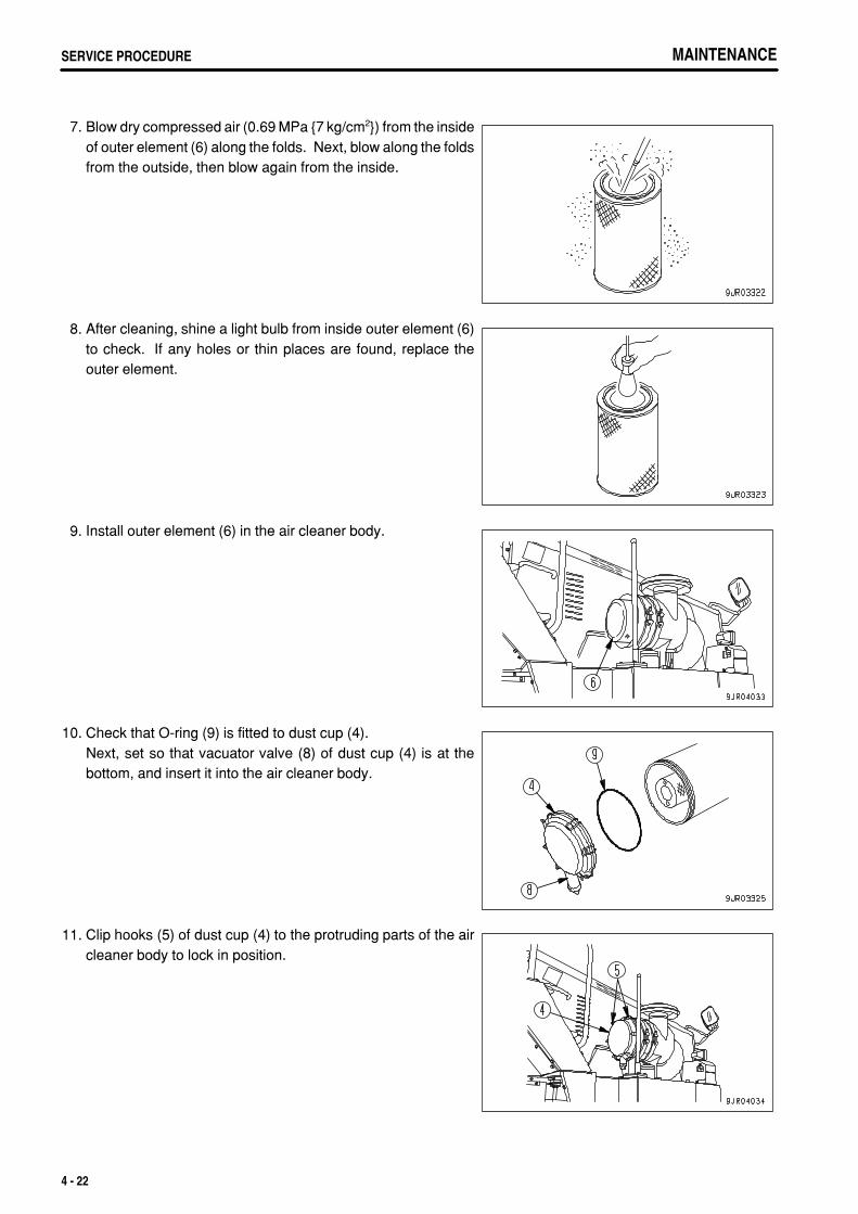
.
MAINTENANCESERVICE PROCEDURE MAINTENANCESERVICE PROCEDURE
7. Blow dry compressed air (0.69 MPa {7 kg/cm2}) from the insideof outer element (6) along the folds. Next, blow along the foldsfrom the outside, then blow again from the inside.
8. After cleaning, shine a light bulb from inside outer element (6)to check. If any holes or thin places are found, replace theouter element.
9. Install outer element (6) in the air cleaner body.
10. Check that O-ring (9) is fitted to dust cup (4).Next, set so that vacuator valve (8) of dust cup (4) is at thebottom, and insert it into the air cleaner body.
11. Clip hooks (5) of dust cup (4) to the protruding parts of the aircleaner body to lock in position.
4 - 22
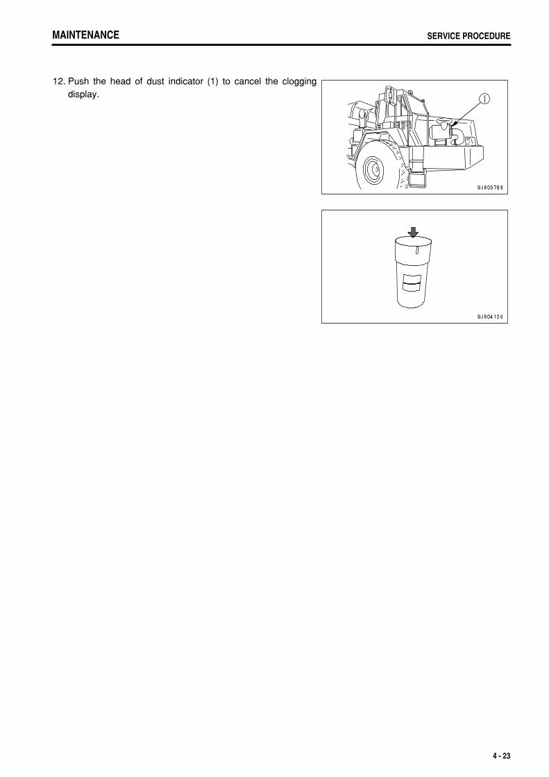
.
MAINTENANCE SERVICE PROCEDUREMAINTENANCE SERVICE PROCEDURE
12. Push the head of dust indicator (1) to cancel the cloggingdisplay.
4 - 23
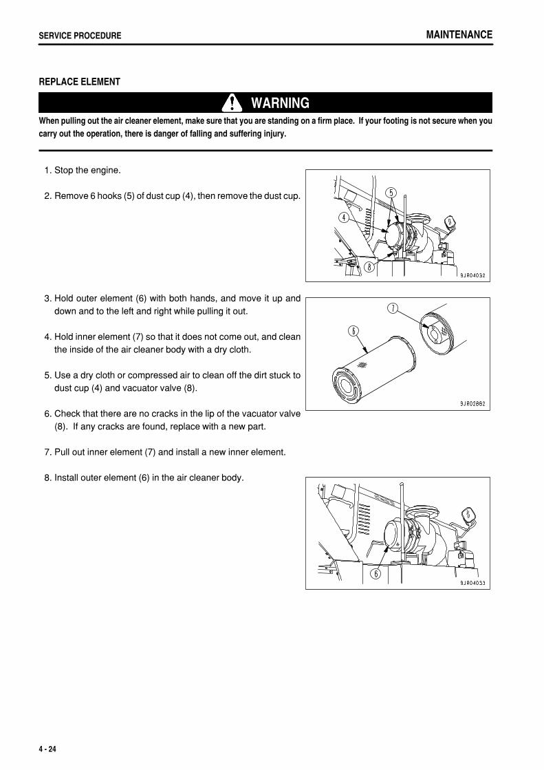
.
MAINTENANCESERVICE PROCEDURE
REPLACE ELEMENT
WARNINGWhen pulling out the air cleaner element, make sure that you are standing on a firm place. If your footing is not secure when youcarry out the operation, there is danger of falling and suffering injury.
1. Stop the engine.
2. Remove 6 hooks (5) of dust cup (4), then remove the dust cup.
3. Hold outer element (6) with both hands, and move it up anddown and to the left and right while pulling it out.
4. Hold inner element (7) so that it does not come out, and cleanthe inside of the air cleaner body with a dry cloth.
5. Use a dry cloth or compressed air to clean off the dirt stuck todust cup (4) and vacuator valve (8).
6. Check that there are no cracks in the lip of the vacuator valve(8). If any cracks are found, replace with a new part.
7. Pull out inner element (7) and install a new inner element.
8. Install outer element (6) in the air cleaner body.
4 - 24
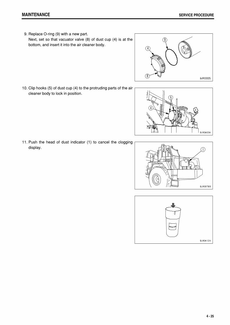
.
MAINTENANCE SERVICE PROCEDUREMAINTENANCE SERVICE PROCEDURE
9. Replace O-ring (9) with a new part.Next, set so that vacuator valve (8) of dust cup (4) is at thebottom, and insert it into the air cleaner body.
10. Clip hooks (5) of dust cup (4) to the protruding parts of the aircleaner body to lock in position.
11. Push the head of dust indicator (1) to cancel the cloggingdisplay.
4 - 25
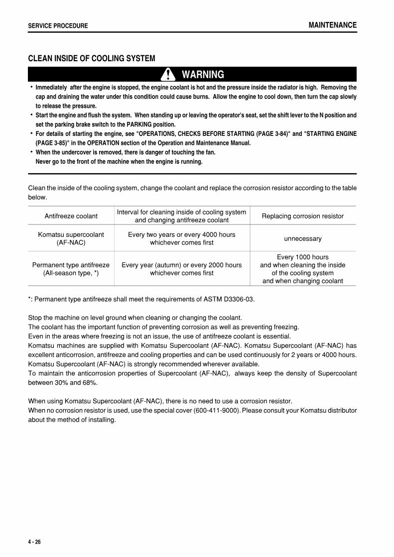
.
MAINTENANCESERVICE PROCEDURE
CLEAN INSIDE OF COOLING SYSTEM
WARNINGImmediately after the engine is stopped, the engine coolant is hot and the pressure inside the radiator is high. Removing thecap and draining the water under this condition could cause burns. Allow the engine to cool down, then turn the cap slowlyto release the pressure.Start the engine and flush the system. When standing up or leaving the operator's seat, set the shift lever to the N position andset the parking brake switch to the PARKING position.For details of starting the engine, see "OPERATIONS, CHECKS BEFORE STARTING (PAGE 3-84)" and "STARTING ENGINE(PAGE 3-85)" in the OPERATION section of the Operation and Maintenance Manual.When the undercover is removed, there is danger of touching the fan.Never go to the front of the machine when the engine is running.
Clean the inside of the cooling system, change the coolant and replace the corrosion resistor according to the tablebelow.
Antifreeze coolantInterval for cleaning inside of cooling system
and changing antifreeze coolantReplacing corrosion resistor
Komatsu supercoolant(AF-NAC)
Every two years or every 4000 hourswhichever comes first
unnecessary
Permanent type antifreeze(All-season type, *)
Every year (autumn) or every 2000 hourswhichever comes first
Every 1000 hoursand when cleaning the inside
of the cooling systemand when changing coolant
*: Permanent type antifreeze shall meet the requirements of ASTM D3306-03.
Stop the machine on level ground when cleaning or changing the coolant.The coolant has the important function of preventing corrosion as well as preventing freezing.Even in the areas where freezing is not an issue, the use of antifreeze coolant is essential.Komatsu machines are supplied with Komatsu Supercoolant (AF-NAC). Komatsu Supercoolant (AF-NAC) hasexcellent anticorrosion, antifreeze and cooling properties and can be used continuously for 2 years or 4000 hours.Komatsu Supercoolant (AF-NAC) is strongly recommended wherever available.To maintain the anticorrosion properties of Supercoolant (AF-NAC), always keep the density of Supercoolantbetween 30% and 68%.
When using Komatsu Supercoolant (AF-NAC), there is no need to use a corrosion resistor. When no corrosion resistor is used, use the special cover (600-411-9000). Please consult your Komatsu distributorabout the method of installing.
4 - 26
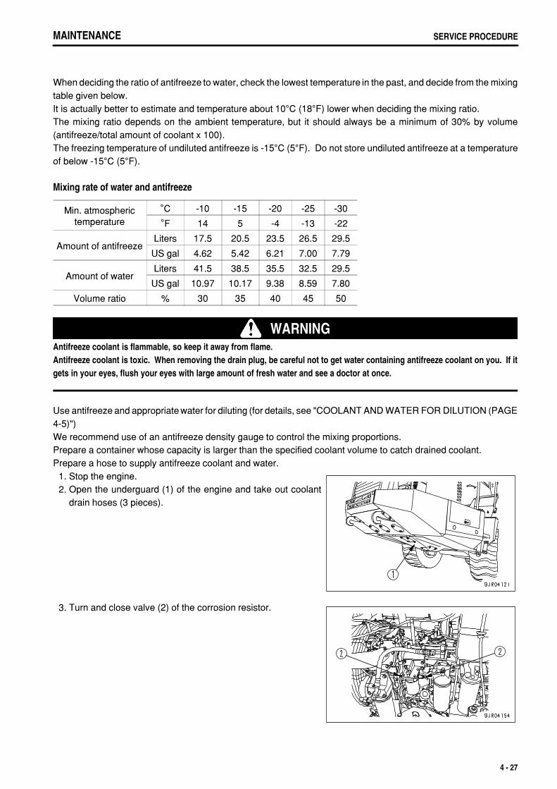
.
MAINTENANCE SERVICE PROCEDURE
When deciding the ratio of antifreeze to water, check the lowest temperature in the past, and decide from the mixingtable given below.It is actually better to estimate and temperature about 10°C (18°F) lower when deciding the mixing ratio.The mixing ratio depends on the ambient temperature, but it should always be a minimum of 30% by volume(antifreeze/total amount of coolant x 100).The freezing temperature of undiluted antifreeze is -15°C (5°F). Do not store undiluted antifreeze at a temperatureof below -15°C (5°F).
Mixing rate of water and antifreeze
Min. atmospherictemperature
°C -10 -15 -20 -25 -30
°F 14 5 -4 -13 -22
Amount of antifreezeLiters 17.5 20.5 23.5 26.5 29.5
US gal 4.62 5.42 6.21 7.00 7.79
Amount of waterLiters 41.5 38.5 35.5 32.5 29.5
US gal 10.97 10.17 9.38 8.59 7.80
Volume ratio % 30 35 40 45 50
WARNINGAntifreeze coolant is flammable, so keep it away from flame.Antifreeze coolant is toxic. When removing the drain plug, be careful not to get water containing antifreeze coolant on you. If itgets in your eyes, flush your eyes with large amount of fresh water and see a doctor at once.
Use antifreeze and appropriate water for diluting (for details, see "COOLANT AND WATER FOR DILUTION (PAGE4-5)")We recommend use of an antifreeze density gauge to control the mixing proportions.Prepare a container whose capacity is larger than the specified coolant volume to catch drained coolant.Prepare a hose to supply antifreeze coolant and water. 1. Stop the engine. 2. Open the underguard (1) of the engine and take out coolant
drain hoses (3 pieces).
3. Turn and close valve (2) of the corrosion resistor.
4 - 27
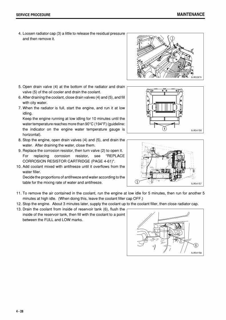
.
MAINTENANCESERVICE PROCEDURE MAINTENANCESERVICE PROCEDURE
4. Loosen radiator cap (3) a little to release the residual pressureand then remove it.
5. Open drain valve (4) at the bottom of the radiator and drainvalve (5) of the oil cooler and drain the coolant.
6. After draining the coolant, close drain valves (4) and (5), and fillwith city water.
7. When the radiator is full, start the engine, and run it at lowidling.Keep the engine running at low idling for 10 minutes until thewater temperature reaches more than 90°C (194°F) (guideline:the indicator on the engine water temperature gauge ishorizontal).
8. Stop the engine, open drain valves (4) and (5), and drain thewater. After draining the water, close them.
9. Replace the corrosion resistor, then turn valve (2) to open it.For replacing corrosion resistor, see "REPLACECORROSION RESISTOR CARTRIDGE (PAGE 4-61)".
10. Add coolant mixed with antifreeze until it overflows from thewater filler.Decide the proportions of antifreeze and water according to thetable for the mixing rate of water and antifreeze.
11. To remove the air contained in the coolant, run the engine at low idle for 5 minutes, then run for another 5minutes at high idle. (When doing this, leave the coolant filler cap OFF.)
12. Stop the engine. About 3 minutes later, supply the coolant up to the coolant filler, then close radiator cap.13. Drain the coolant from inside of reservoir tank (6), flush the
inside of the reservoir tank, then fill with the coolant to a pointbetween the FULL and LOW marks.
4 - 28

.
MAINTENANCE SERVICE PROCEDURE
CHECK LEVEL OF WINDOW WASHER FLUID, ADD FLUIDCarry out this check if there is air in the window washer fluid.
Check the level of the fluid in window washer tank (1), and if it islow, fill with automobile window washer fluid.Be careful not to let dirt or dust get in when adding fluid.
When operating at below freezing point, use fluid with antifreeze.
CLEAN AIR CONDITIONER AIR FILTERIf the air filter at the suction port of the air conditioner unit or the air filter at the fresh air intake port become clogged,the cooling or heating capacity will drop, so clean the filters once a week.
1. Open cover (1) on the side of the cab. 2. Pull out the air filter (FRESH filter) and clean it with
compressed air.
3. Open cover (2) at the right side at the rear of the operator'sseat.
4. Pull out the air filter (RECIRC filter), then use a weak jet ofcompressed air to blow off the dust or clean with a soft brush.
4 - 29
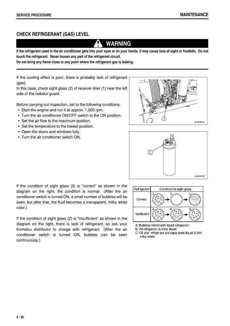
.
MAINTENANCESERVICE PROCEDURE
CHECK REFRIGERANT (GAS) LEVEL
WARNINGIf the refrigerant used in the air conditioner gets into your eyes or on your hands, it may cause loss of sight or frostbite. Do nottouch the refrigerant. Never loosen any part of the refrigerant circuit.Do not bring any flame close to any point where the refrigerant gas is leaking.
If the cooling effect is poor, there is probably lack of refrigerant(gas).In this case, check sight glass (2) of receiver drier (1) near the leftside of the radiator guard.
Before carrying out inspection, set to the following conditions.Start the engine and run it at approx. 1,500 rpm.Turn the air conditioner ON/OFF switch to the ON position.Set the air flow to the maximum position.Set the temperature to the lowest position.Open the doors and windows fully.Turn the air conditioner switch ON.
If the condition of sight glass (2) is "correct" as shown in thediagram on the right, the condition is normal. (After the airconditioner switch is turned ON, a small number of bubbles will beseen, but after that, the fluid becomes a transparent, milky whitecolor.)
If the condition of sight glass (2) is "insufficient" as shown in thediagram on the right, there is lack of refrigerant, so ask yourKomatsu distributor to charge with refrigerant. (After the airconditioner switch is turned ON, bubbles can be seencontinuously.)
4 - 30
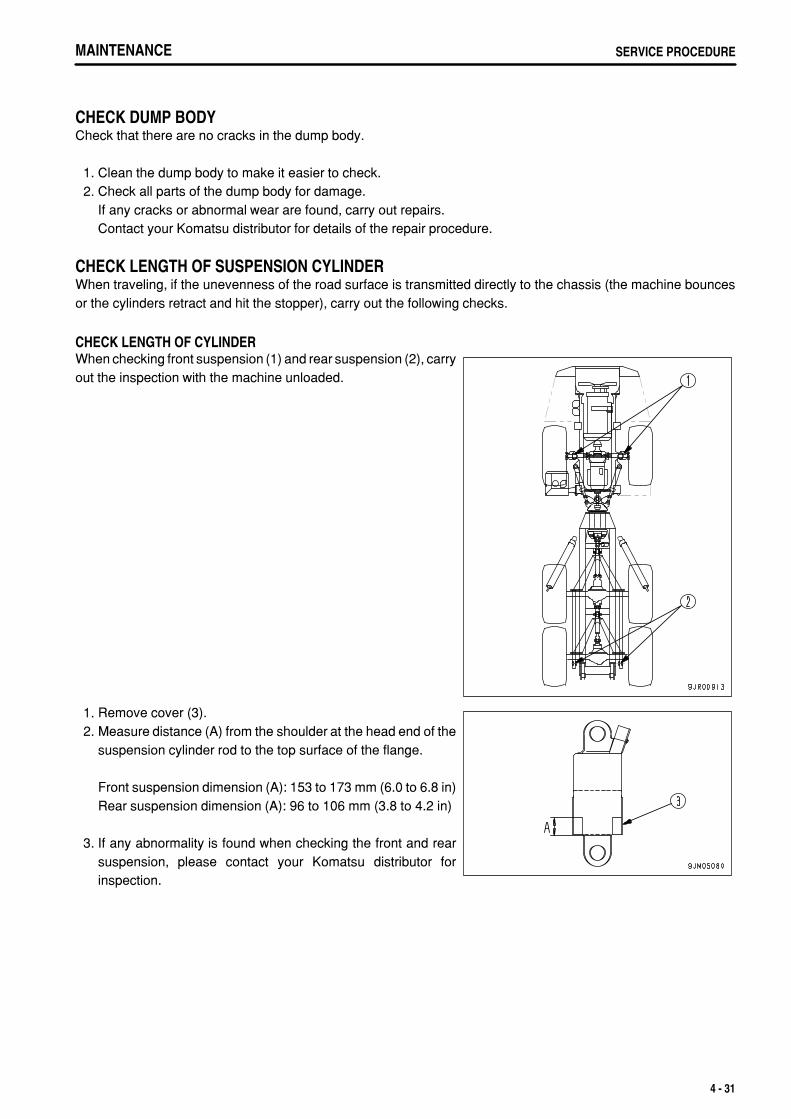
.
MAINTENANCE SERVICE PROCEDURE
CHECK DUMP BODYCheck that there are no cracks in the dump body.
1. Clean the dump body to make it easier to check. 2. Check all parts of the dump body for damage.
If any cracks or abnormal wear are found, carry out repairs.Contact your Komatsu distributor for details of the repair procedure.
CHECK LENGTH OF SUSPENSION CYLINDERWhen traveling, if the unevenness of the road surface is transmitted directly to the chassis (the machine bouncesor the cylinders retract and hit the stopper), carry out the following checks.
CHECK LENGTH OF CYLINDERWhen checking front suspension (1) and rear suspension (2), carryout the inspection with the machine unloaded.
1. Remove cover (3). 2. Measure distance (A) from the shoulder at the head end of the
suspension cylinder rod to the top surface of the flange.
Front suspension dimension (A): 153 to 173 mm (6.0 to 6.8 in)Rear suspension dimension (A): 96 to 106 mm (3.8 to 4.2 in)
3. If any abnormality is found when checking the front and rearsuspension, please contact your Komatsu distributor forinspection.
4 - 31
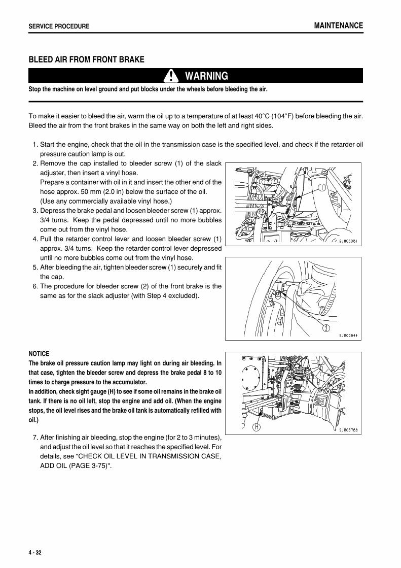
.
MAINTENANCESERVICE PROCEDURE
BLEED AIR FROM FRONT BRAKE
WARNINGStop the machine on level ground and put blocks under the wheels before bleeding the air.
To make it easier to bleed the air, warm the oil up to a temperature of at least 40°C (104°F) before bleeding the air.Bleed the air from the front brakes in the same way on both the left and right sides.
1. Start the engine, check that the oil in the transmission case is the specified level, and check if the retarder oilpressure caution lamp is out.
2. Remove the cap installed to bleeder screw (1) of the slackadjuster, then insert a vinyl hose.Prepare a container with oil in it and insert the other end of thehose approx. 50 mm (2.0 in) below the surface of the oil.(Use any commercially available vinyl hose.)
3. Depress the brake pedal and loosen bleeder screw (1) approx.3/4 turns. Keep the pedal depressed until no more bubblescome out from the vinyl hose.
4. Pull the retarder control lever and loosen bleeder screw (1)approx. 3/4 turns. Keep the retarder control lever depresseduntil no more bubbles come out from the vinyl hose.
5. After bleeding the air, tighten bleeder screw (1) securely and fitthe cap.
6. The procedure for bleeder screw (2) of the front brake is thesame as for the slack adjuster (with Step 4 excluded).
NOTICEThe brake oil pressure caution lamp may light on during air bleeding. Inthat case, tighten the bleeder screw and depress the brake pedal 8 to 10times to charge pressure to the accumulator.In addition, check sight gauge (H) to see if some oil remains in the brake oiltank. If there is no oil left, stop the engine and add oil. (When the enginestops, the oil level rises and the brake oil tank is automatically refilled withoil.)
7. After finishing air bleeding, stop the engine (for 2 to 3 minutes),and adjust the oil level so that it reaches the specified level. Fordetails, see "CHECK OIL LEVEL IN TRANSMISSION CASE,ADD OIL (PAGE 3-75)".
4 - 32
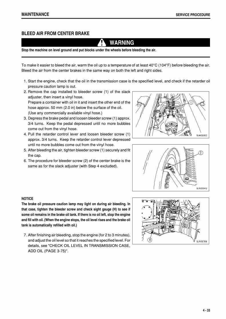
.
MAINTENANCE SERVICE PROCEDURE
BLEED AIR FROM CENTER BRAKE
WARNINGStop the machine on level ground and put blocks under the wheels before bleeding the air.
To make it easier to bleed the air, warm the oil up to a temperature of at least 40°C (104°F) before bleeding the air.Bleed the air from the center brakes in the same way on both the left and right sides.
1. Start the engine, check that the oil in the transmission case is the specified level, and check if the retarder oilpressure caution lamp is out.
2. Remove the cap installed to bleeder screw (1) of the slackadjuster, then insert a vinyl hose.Prepare a container with oil in it and insert the other end of thehose approx. 50 mm (2.0 in) below the surface of the oil.(Use any commercially available vinyl hose.)
3. Depress the brake pedal and loosen bleeder screw (1) approx.3/4 turns. Keep the pedal depressed until no more bubblescome out from the vinyl hose.
4. Pull the retarder control lever and loosen bleeder screw (1)approx. 3/4 turns. Keep the retarder control lever depresseduntil no more bubbles come out from the vinyl hose.
5. After bleeding the air, tighten bleeder screw (1) securely and fitthe cap.
6. The procedure for bleeder screw (2) of the center brake is thesame as for the slack adjuster (with Step 4 excluded).
NOTICEThe brake oil pressure caution lamp may light on during air bleeding. Inthat case, tighten the bleeder screw and check sight gauge (H) to see ifsome oil remains in the brake oil tank. If there is no oil left, stop the engineand fill with oil. (When the engine stops, the oil level rises and the brake oiltank is automatically refilled with oil.)
7. After finishing air bleeding, stop the engine (for 2 to 3 minutes),and adjust the oil level so that it reaches the specified level. Fordetails, see "CHECK OIL LEVEL IN TRANSMISSION CASE,ADD OIL (PAGE 3-75)".
4 - 33
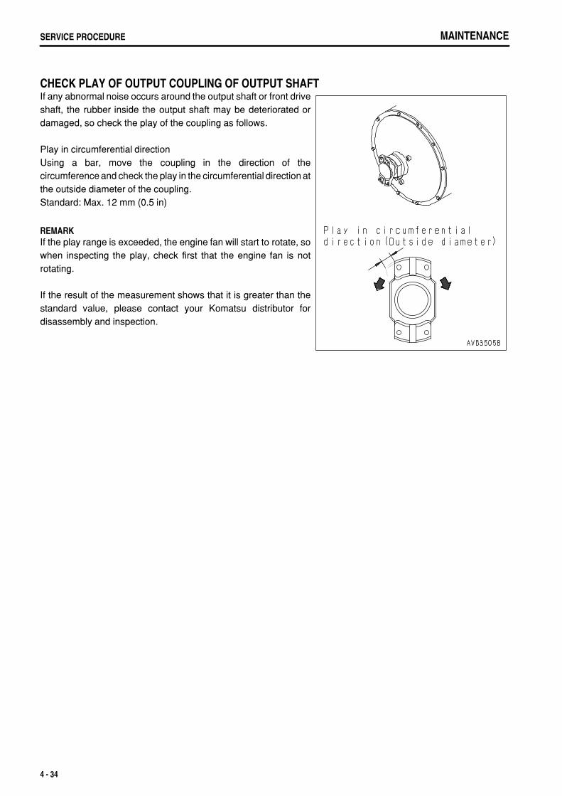
.
MAINTENANCESERVICE PROCEDURE
CHECK PLAY OF OUTPUT COUPLING OF OUTPUT SHAFTIf any abnormal noise occurs around the output shaft or front driveshaft, the rubber inside the output shaft may be deteriorated ordamaged, so check the play of the coupling as follows.
Play in circumferential directionUsing a bar, move the coupling in the direction of thecircumference and check the play in the circumferential direction atthe outside diameter of the coupling.Standard: Max. 12 mm (0.5 in)
REMARKIf the play range is exceeded, the engine fan will start to rotate, sowhen inspecting the play, check first that the engine fan is notrotating.
If the result of the measurement shows that it is greater than thestandard value, please contact your Komatsu distributor fordisassembly and inspection.
4 - 34
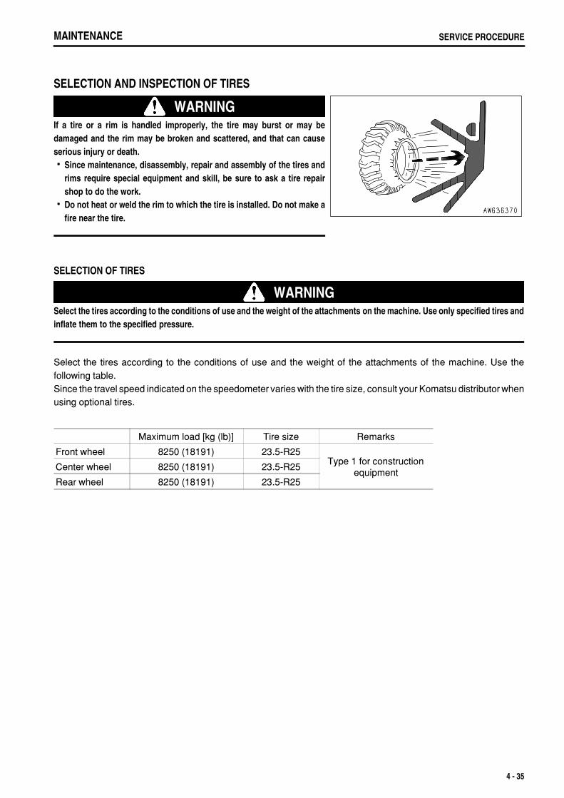
.
MAINTENANCE SERVICE PROCEDURE
SELECTION AND INSPECTION OF TIRES
WARNINGIf a tire or a rim is handled improperly, the tire may burst or may bedamaged and the rim may be broken and scattered, and that can causeserious injury or death.
Since maintenance, disassembly, repair and assembly of the tires andrims require special equipment and skill, be sure to ask a tire repairshop to do the work.Do not heat or weld the rim to which the tire is installed. Do not make afire near the tire.
SELECTION OF TIRES
WARNINGSelect the tires according to the conditions of use and the weight of the attachments on the machine. Use only specified tires andinflate them to the specified pressure.
Select the tires according to the conditions of use and the weight of the attachments of the machine. Use thefollowing table.Since the travel speed indicated on the speedometer varies with the tire size, consult your Komatsu distributor whenusing optional tires.
Maximum load [kg (lb)] Tire size Remarks
Front wheel 8250 (18191) 23.5-R25Type 1 for construction
equipmentCenter wheel 8250 (18191) 23.5-R25
Rear wheel 8250 (18191) 23.5-R25
4 - 35
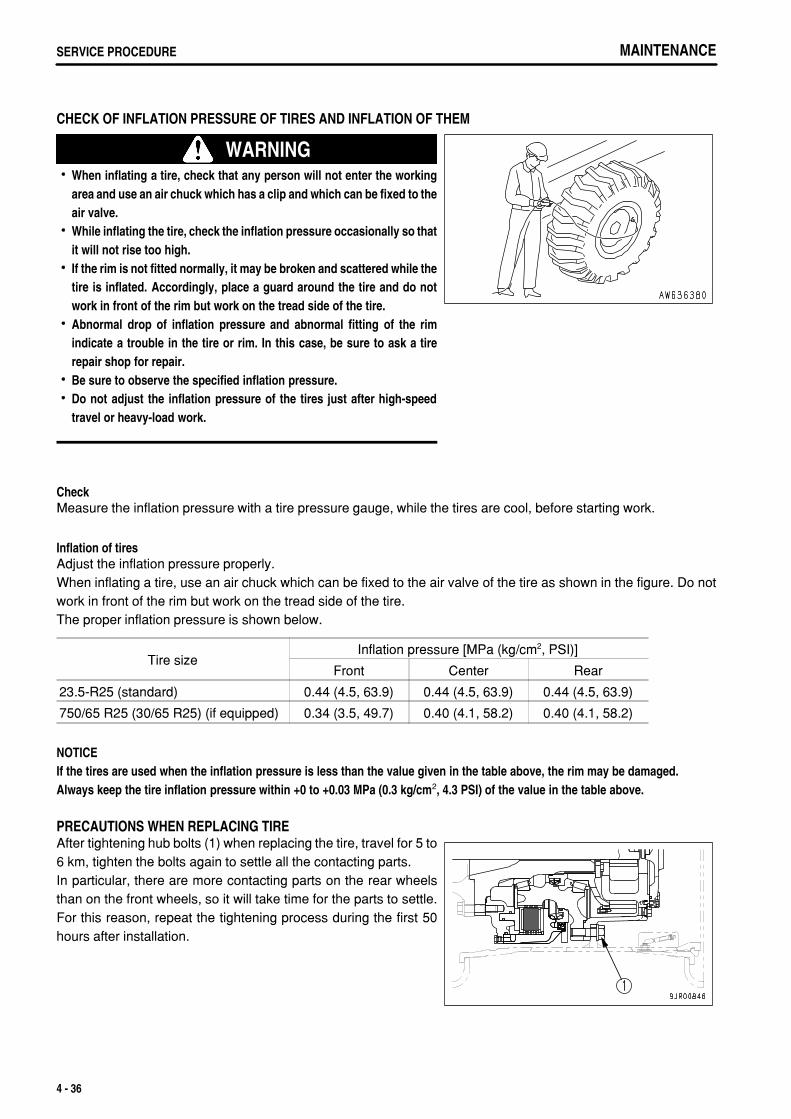
.
MAINTENANCESERVICE PROCEDURE
CHECK OF INFLATION PRESSURE OF TIRES AND INFLATION OF THEM
WARNINGWhen inflating a tire, check that any person will not enter the workingarea and use an air chuck which has a clip and which can be fixed to theair valve.While inflating the tire, check the inflation pressure occasionally so thatit will not rise too high.If the rim is not fitted normally, it may be broken and scattered while thetire is inflated. Accordingly, place a guard around the tire and do notwork in front of the rim but work on the tread side of the tire.Abnormal drop of inflation pressure and abnormal fitting of the rimindicate a trouble in the tire or rim. In this case, be sure to ask a tirerepair shop for repair.Be sure to observe the specified inflation pressure.Do not adjust the inflation pressure of the tires just after high-speedtravel or heavy-load work.
CheckMeasure the inflation pressure with a tire pressure gauge, while the tires are cool, before starting work.
Inflation of tiresAdjust the inflation pressure properly.When inflating a tire, use an air chuck which can be fixed to the air valve of the tire as shown in the figure. Do notwork in front of the rim but work on the tread side of the tire.The proper inflation pressure is shown below.
Tire sizeInflation pressure [MPa (kg/cm2, PSI)]
Front Center Rear
23.5-R25 (standard) 0.44 (4.5, 63.9) 0.44 (4.5, 63.9) 0.44 (4.5, 63.9)
750/65 R25 (30/65 R25) (if equipped) 0.34 (3.5, 49.7) 0.40 (4.1, 58.2) 0.40 (4.1, 58.2)
NOTICEIf the tires are used when the inflation pressure is less than the value given in the table above, the rim may be damaged.Always keep the tire inflation pressure within +0 to +0.03 MPa (0.3 kg/cm2, 4.3 PSI) of the value in the table above.
PRECAUTIONS WHEN REPLACING TIREAfter tightening hub bolts (1) when replacing the tire, travel for 5 to6 km, tighten the bolts again to settle all the contacting parts.In particular, there are more contacting parts on the rear wheelsthan on the front wheels, so it will take time for the parts to settle.For this reason, repeat the tightening process during the first 50hours after installation.
4 - 36
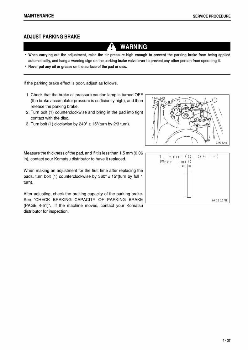
.
MAINTENANCE SERVICE PROCEDURE
ADJUST PARKING BRAKE
WARNINGWhen carrying out the adjustment, raise the air pressure high enough to prevent the parking brake from being appliedautomatically, and hang a warning sign on the parking brake valve lever to prevent any other person from operating it.Never put any oil or grease on the surface of the pad or disc.
If the parking brake effect is poor, adjust as follows.
1. Check that the brake oil pressure caution lamp is turned OFF(the brake accumulator pressure is sufficiently high), and thenrelease the parking brake.
2. Turn bolt (1) counterclockwise and bring in the pad into tightcontact with the disc.
3. Turn bolt (1) clockwise by 240° ± 15°(turn by 2/3 turn).
Measure the thickness of the pad, and if it is less than 1.5 mm (0.06in), contact your Komatsu distributor to have it replaced.
When making an adjustment for the first time after replacing thepads, turn bolt (1) counterclockwise by 360° ± 15°(turn by full 1turn).
After adjusting, check the braking capacity of the parking brake.See "CHECK BRAKING CAPACITY OF PARKING BRAKE(PAGE 4-51)". If the machine moves, contact your Komatsudistributor for inspection.
4 - 37

.
MAINTENANCESERVICE PROCEDURE
CLEAN HYDRAULIC TANK STRAINER
WARNINGThe parts and oil are at high temperature immediately after the engine is stopped, and may cause burns. Wait for thetemperature to go down before starting the work.When removing the oil filler cap, turn it slowly to release the internal pressure, then remove it.
1. Raise the front side of the cab. For details, see "CAB TILT OPERATION (PAGE 3-107)". 2. Turn the cap of oil filler (F) to release the internal pressure
before removing the cap.
3. Remove cap (1) of the hydraulic tank strainer and clean thestrainer and strainer case.
4. After checking and cleaning, set the strainer in the case andtighten cap (1).
5. Install the cap of oil filler (F).
4 - 38
.
MAINTENANCE SERVICE PROCEDURE
CHECK BEFORE STARTINGFor details of the following items, see "CHECK BEFORE STARTING (PAGE 3-72)".
Check coolant level, add coolantCheck dust indicatorCheck oil level in engine oil pan, add oilCheck oil level in transmission case, add oilCheck oil level in hydraulic tank, add oilDrain water, sediment from fuel tankCheck fuel level, add fuelCheck wheel hub bolts, tightenCheck central warning lamp, alarm buzzer, monitor lamps and metersCheck braking effectCheck manual emergency steeringCheck auto-emergency steeringCheck backup alarmCheck electric wiringCheck inflation pressure of tiresCheck water separatorDoes body positioner operate normally?Are the cab mounting bolts and pins are free from looseness and breakage?
4 - 39
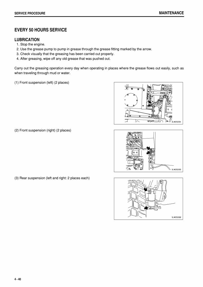
.
MAINTENANCESERVICE PROCEDURE
EVERY 50 HOURS SERVICE
LUBRICATION 1. Stop the engine. 2. Use the grease pump to pump in grease through the grease fitting marked by the arrow. 3. Check visually that the greasing has been carried out properly. 4. After greasing, wipe off any old grease that was pushed out.
Carry out the greasing operation every day when operating in places where the grease flows out easily, such aswhen traveling through mud or water.
(1) Front suspension (left) (2 places)
(2) Front suspension (right) (2 places)
(3) Rear suspension (left and right: 2 places each)
4 - 40
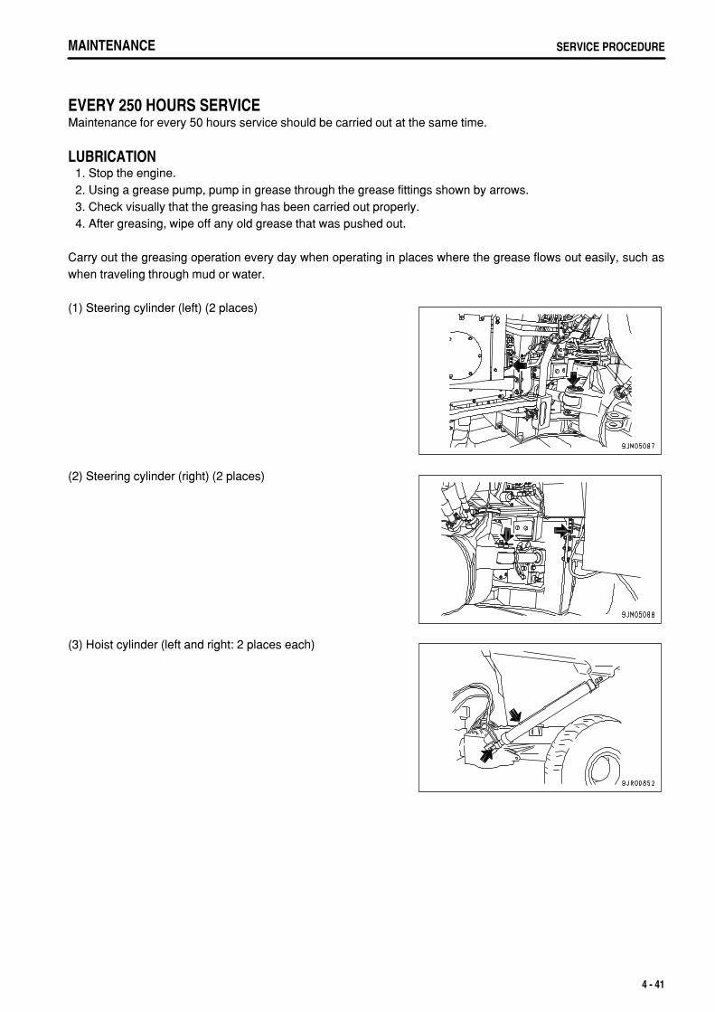
.
MAINTENANCE SERVICE PROCEDURE
EVERY 250 HOURS SERVICEMaintenance for every 50 hours service should be carried out at the same time.
LUBRICATION 1. Stop the engine. 2. Using a grease pump, pump in grease through the grease fittings shown by arrows. 3. Check visually that the greasing has been carried out properly. 4. After greasing, wipe off any old grease that was pushed out.
Carry out the greasing operation every day when operating in places where the grease flows out easily, such aswhen traveling through mud or water.
(1) Steering cylinder (left) (2 places)
(2) Steering cylinder (right) (2 places)
(3) Hoist cylinder (left and right: 2 places each)
4 - 41
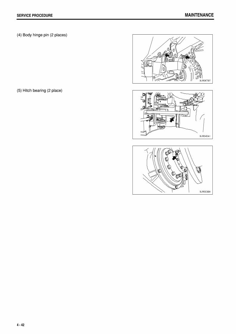
.
MAINTENANCESERVICE PROCEDURE MAINTENANCESERVICE PROCEDURE
(4) Body hinge pin (2 places)
(5) Hitch bearing (2 place)
4 - 42
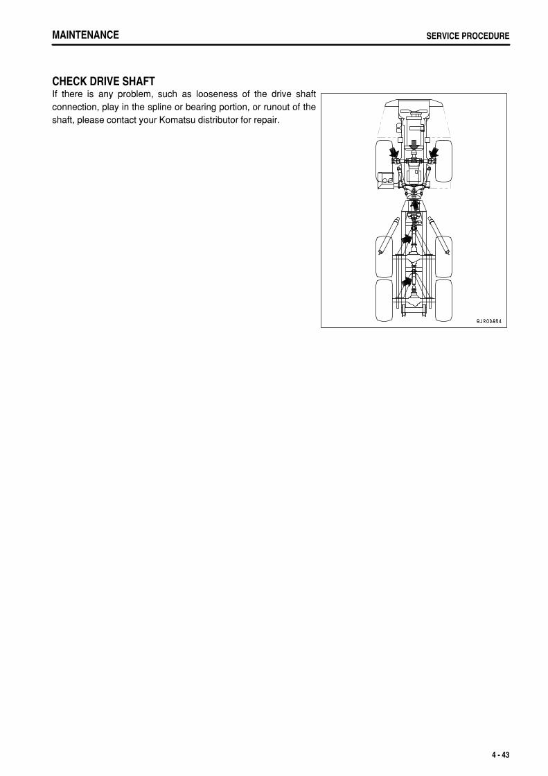
.
MAINTENANCE SERVICE PROCEDURE
CHECK DRIVE SHAFTIf there is any problem, such as looseness of the drive shaftconnection, play in the spline or bearing portion, or runout of theshaft, please contact your Komatsu distributor for repair.
4 - 43
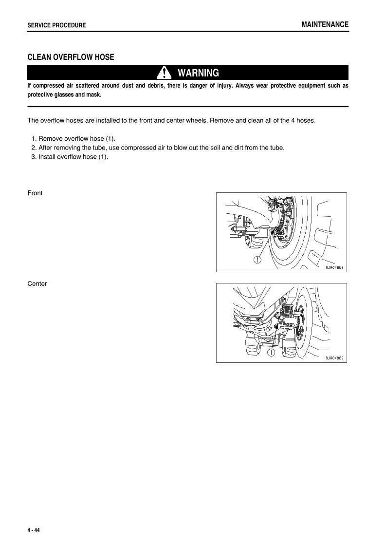
.
MAINTENANCESERVICE PROCEDURE
CLEAN OVERFLOW HOSE
WARNINGIf compressed air scattered around dust and debris, there is danger of injury. Always wear protective equipment such asprotective glasses and mask.
The overflow hoses are installed to the front and center wheels. Remove and clean all of the 4 hoses.
1. Remove overflow hose (1). 2. After removing the tube, use compressed air to blow out the soil and dirt from the tube. 3. Install overflow hose (1).
Front
Center
4 - 44
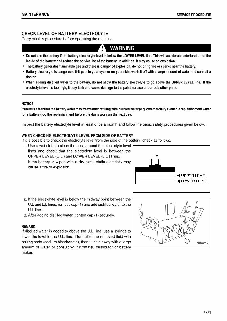
.
MAINTENANCE SERVICE PROCEDURE
CHECK LEVEL OF BATTERY ELECTROLYTECarry out this procedure before operating the machine.
WARNINGDo not use the battery if the battery electrolyte level is below the LOWER LEVEL line. This will accelerate deterioration of theinside of the battery and reduce the service life of the battery. In addition, it may cause an explosion.The battery generates flammable gas and there is danger of explosion, do not bring fire or sparks near the battery.Battery electrolyte is dangerous. If it gets in your eyes or on your skin, wash it off with a large amount of water and consult adoctor.When adding distilled water to the battery, do not allow the battery electrolyte to go above the UPPER LEVEL line. If theelectrolyte level is too high, it may leak and cause damage to the paint surface or corrode other parts.
NOTICEIf there is a fear that the battery water may freeze after refilling with purified water (e.g. commercially available replenishment waterfor a battery), do the replenishment before the day's work on the next day.
Inspect the battery electrolyte level at least once a month and follow the basic safety procedures given below.
WHEN CHECKING ELECTROLYTE LEVEL FROM SIDE OF BATTERYIf it is possible to check the electrolyte level from the side of the battery, check as follows. 1. Use a wet cloth to clean the area around the electrolyte level
lines and check that the electrolyte level is between theUPPER LEVEL (U.L.) and LOWER LEVEL (L.L.) lines.If the battery is wiped with a dry cloth, static electricity maycause a fire or explosion.
2. If the electrolyte level is below the midway point between theU.L and L.L lines, remove cap (1) and add distilled water to theU.L line.
3. After adding distilled water, tighten cap (1) securely.
REMARKIf distilled water is added to above the U.L. line, use a syringe tolower the level to the U.L. line. Neutralize the removed fluid withbaking soda (sodium bicarbonate), then flush it away with a largeamount of water or consult your Komatsu distributor or batterymaker.
4 - 45
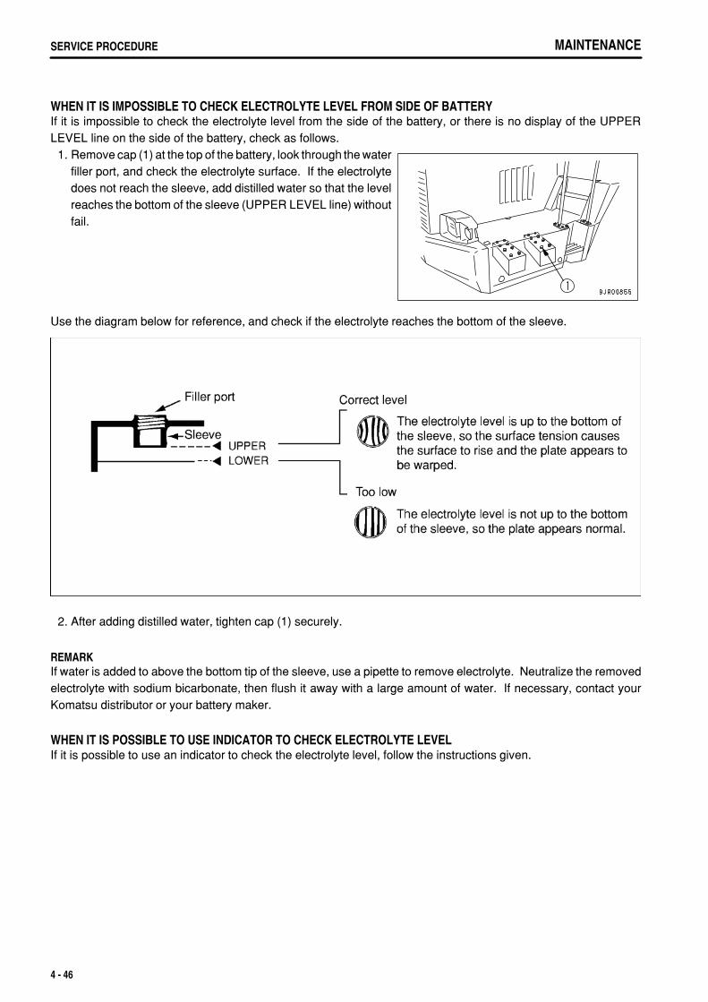
.
MAINTENANCESERVICE PROCEDURE
WHEN IT IS IMPOSSIBLE TO CHECK ELECTROLYTE LEVEL FROM SIDE OF BATTERYIf it is impossible to check the electrolyte level from the side of the battery, or there is no display of the UPPERLEVEL line on the side of the battery, check as follows. 1. Remove cap (1) at the top of the battery, look through the water
filler port, and check the electrolyte surface. If the electrolytedoes not reach the sleeve, add distilled water so that the levelreaches the bottom of the sleeve (UPPER LEVEL line) withoutfail.
Use the diagram below for reference, and check if the electrolyte reaches the bottom of the sleeve.
2. After adding distilled water, tighten cap (1) securely.
REMARKIf water is added to above the bottom tip of the sleeve, use a pipette to remove electrolyte. Neutralize the removedelectrolyte with sodium bicarbonate, then flush it away with a large amount of water. If necessary, contact yourKomatsu distributor or your battery maker.
WHEN IT IS POSSIBLE TO USE INDICATOR TO CHECK ELECTROLYTE LEVELIf it is possible to use an indicator to check the electrolyte level, follow the instructions given.
4 - 46
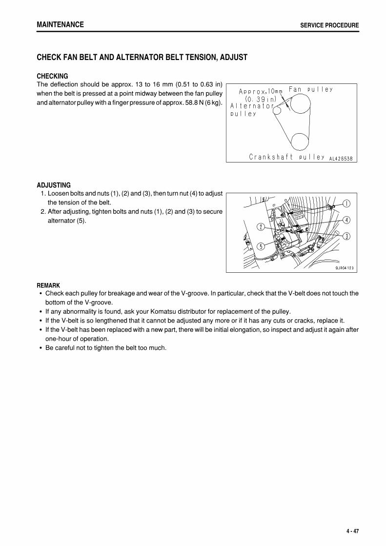
.
MAINTENANCE SERVICE PROCEDURE
CHECK FAN BELT AND ALTERNATOR BELT TENSION, ADJUST
CHECKINGThe deflection should be approx. 13 to 16 mm (0.51 to 0.63 in)when the belt is pressed at a point midway between the fan pulleyand alternator pulley with a finger pressure of approx. 58.8 N (6 kg).
ADJUSTING 1. Loosen bolts and nuts (1), (2) and (3), then turn nut (4) to adjust
the tension of the belt. 2. After adjusting, tighten bolts and nuts (1), (2) and (3) to secure
alternator (5).
REMARKCheck each pulley for breakage and wear of the V-groove. In particular, check that the V-belt does not touch thebottom of the V-groove.If any abnormality is found, ask your Komatsu distributor for replacement of the pulley.If the V-belt is so lengthened that it cannot be adjusted any more or if it has any cuts or cracks, replace it.If the V-belt has been replaced with a new part, there will be initial elongation, so inspect and adjust it again afterone-hour of operation.Be careful not to tighten the belt too much.
4 - 47
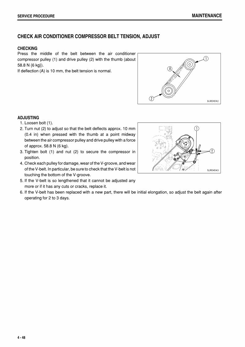
.
MAINTENANCESERVICE PROCEDURE
CHECK AIR CONDITIONER COMPRESSOR BELT TENSION, ADJUST
CHECKINGPress the middle of the belt between the air conditionercompressor pulley (1) and drive pulley (2) with the thumb (about58.8 N {6 kg}).If deflection (A) is 10 mm, the belt tension is normal.
ADJUSTING 1. Loosen bolt (1). 2. Turn nut (2) to adjust so that the belt deflects approx. 10 mm
(0.4 in) when pressed with the thumb at a point midwaybetween the air compressor pulley and drive pulley with a forceof approx. 58.8 N (6 kg).
3. Tighten bolt (1) and nut (2) to secure the compressor inposition.
4. Check each pulley for damage, wear of the V-groove, and wearof the V-belt. In particular, be sure to check that the V-belt is nottouching the bottom of the V-groove.
5. If the V-belt is so lengthened that it cannot be adjusted anymore or if it has any cuts or cracks, replace it.
6. If the V-belt has been replaced with a new part, there will be initial elongation, so adjust the belt again afteroperating for 2 to 3 days.
4 - 48
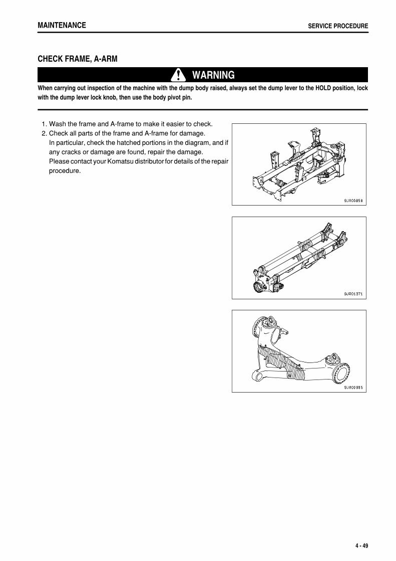
.
MAINTENANCE SERVICE PROCEDURE
CHECK FRAME, A-ARM
WARNINGWhen carrying out inspection of the machine with the dump body raised, always set the dump lever to the HOLD position, lockwith the dump lever lock knob, then use the body pivot pin.
1. Wash the frame and A-frame to make it easier to check. 2. Check all parts of the frame and A-frame for damage.
In particular, check the hatched portions in the diagram, and ifany cracks or damage are found, repair the damage.Please contact your Komatsu distributor for details of the repairprocedure.
4 - 49
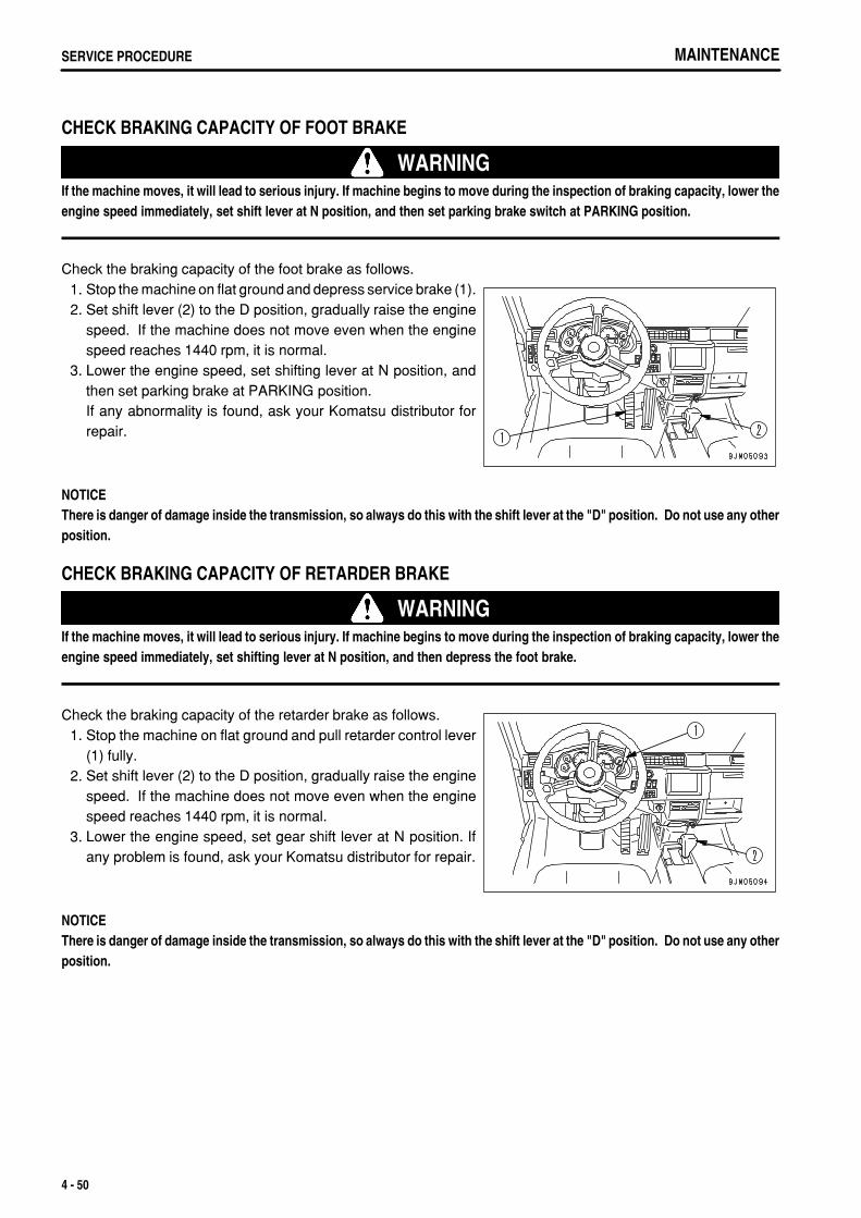
.
MAINTENANCESERVICE PROCEDURE
CHECK BRAKING CAPACITY OF FOOT BRAKE
WARNINGIf the machine moves, it will lead to serious injury. If machine begins to move during the inspection of braking capacity, lower theengine speed immediately, set shift lever at N position, and then set parking brake switch at PARKING position.
Check the braking capacity of the foot brake as follows. 1. Stop the machine on flat ground and depress service brake (1). 2. Set shift lever (2) to the D position, gradually raise the engine
speed. If the machine does not move even when the enginespeed reaches 1440 rpm, it is normal.
3. Lower the engine speed, set shifting lever at N position, andthen set parking brake at PARKING position.If any abnormality is found, ask your Komatsu distributor forrepair.
NOTICEThere is danger of damage inside the transmission, so always do this with the shift lever at the "D" position. Do not use any otherposition.
CHECK BRAKING CAPACITY OF RETARDER BRAKE
WARNINGIf the machine moves, it will lead to serious injury. If machine begins to move during the inspection of braking capacity, lower theengine speed immediately, set shifting lever at N position, and then depress the foot brake.
Check the braking capacity of the retarder brake as follows. 1. Stop the machine on flat ground and pull retarder control lever
(1) fully. 2. Set shift lever (2) to the D position, gradually raise the engine
speed. If the machine does not move even when the enginespeed reaches 1440 rpm, it is normal.
3. Lower the engine speed, set gear shift lever at N position. Ifany problem is found, ask your Komatsu distributor for repair.
NOTICEThere is danger of damage inside the transmission, so always do this with the shift lever at the "D" position. Do not use any otherposition.
4 - 50
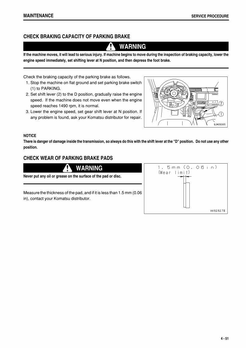
.
MAINTENANCE SERVICE PROCEDURE
CHECK BRAKING CAPACITY OF PARKING BRAKE
WARNINGIf the machine moves, it will lead to serious injury. If machine begins to move during the inspection of braking capacity, lower theengine speed immediately, set shifting lever at N position, and then depress the foot brake.
Check the braking capacity of the parking brake as follows. 1. Stop the machine on flat ground and set parking brake switch
(1) to PARKING. 2. Set shift lever (2) to the D position, gradually raise the engine
speed. If the machine does not move even when the enginespeed reaches 1490 rpm, it is normal.
3. Lower the engine speed, set gear shift lever at N position. Ifany problem is found, ask your Komatsu distributor for repair.
NOTICEThere is danger of damage inside the transmission, so always do this with the shift lever at the "D" position. Do not use any otherposition.
CHECK WEAR OF PARKING BRAKE PADS
WARNINGNever put any oil or grease on the surface of the pad or disc.
Measure the thickness of the pad, and if it is less than 1.5 mm (0.06in), contact your Komatsu distributor.
4 - 51
.
MAINTENANCESERVICE PROCEDURE
CHECK OF ACCUMULATOR GAS PRESSUREFor handling of the accumulator, see "HANDLING SUSPENSION CYLINDER, ACCUMULATOR (PAGE 2-33)".
REMARKIf the engine stops during travel, the brake can be operated with the oil pressure in the accumulator temporarily.
CHECK OF FUNCTION 1. Stop the machine on a flat place and set the parking brake switch to the PARKING position. 2. Start the engine and run it at medium speed for 1 minute, and then stop it. 3. Turn the starting switch to the ON position and depress the brake pedal several times. After the brake pedal is
depressed some times, the brake oil pressure caution lamp lights up.If the brake oil pressure caution lamp lights up when the brake pedal is depressed 4 times or less, the gaspressure in the accumulator may be low. Ask your Komatsu distributor for inspection.If the brake oil pressure caution lamp does not light up when the brake pedal is depressed 5 times, the gaspressure in the accumulator is normal.
REMARKCheck the function within 5 minutes after stopping the engine. If the engine is kept stopped, the gas pressure in theaccumulator lowers and cannot be checked.
4 - 52
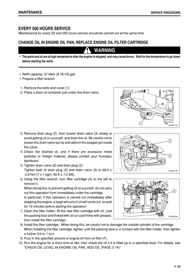
.
MAINTENANCE SERVICE PROCEDURE
EVERY 500 HOURS SERVICEMaintenance for every 50 and 250 hours service should be carried out at the same time.
CHANGE OIL IN ENGINE OIL PAN, REPLACE ENGINE OIL FILTER CARTRIDGE
WARNINGThe parts and oil are at high temperature after the engine is stopped, and may cause burns. Wait for the temperature to go downbefore starting the work.
Refill capacity: 37 liters (9.78 US gal)Prepare a filter wrench
1. Remove the bolts and cover (1). 2. Place a drain oil container just under the drain valve.
3. Remove drain plug (2), then loosen drain valve (3) slowly toavoid getting oil on yourself, and drain the oil. Be careful not toloosen the drain valve too far and deform the stopper pin insidethe valve.
4. Check the drained oil, and if there are excessive metalparticles or foreign material, please contact your Komatsudistributor.
5. Tighten drain valve (3) and drain plug (2).Tighten both of drain plug (2) and drain valve (3) to 68.6 ± 9.8 Nm {7 ± 1 kgm, 50.6 ± 7.2 lbft}.
6. Using the filter wrench, turn filter cartridge (4) to the left toremove it.When doing this, to prevent getting oil on yourself, do not carryout this operation from immediately under the cartridge.In particular, if this operation is carried out immediately afterstopping the engine, a large amount of oil will come out, so waitfor 10 minutes before starting the operation.
7. Clean the filter holder, fill the new filter cartridge with oil, coatthe packing face and thread with oil (or coat thinly with grease),then install the filter cartridge.
8. Install the filter cartridge. When doing this, be careful not to damage the outside cylinder of the cartridge.When installing the filter cartridge, tighten until the packing face is in contact with the filter holder, then tightena further 3/4 to 1 turn.
9. Pour in the specified amount of engine oil from oil filler (F).10. Run the engine for a short time at idle, then check the oil if it is filled up to a specified level. For details, see
"CHECK OIL LEVEL IN ENGINE OIL PAN, ADD OIL (PAGE 3-74)".
4 - 53
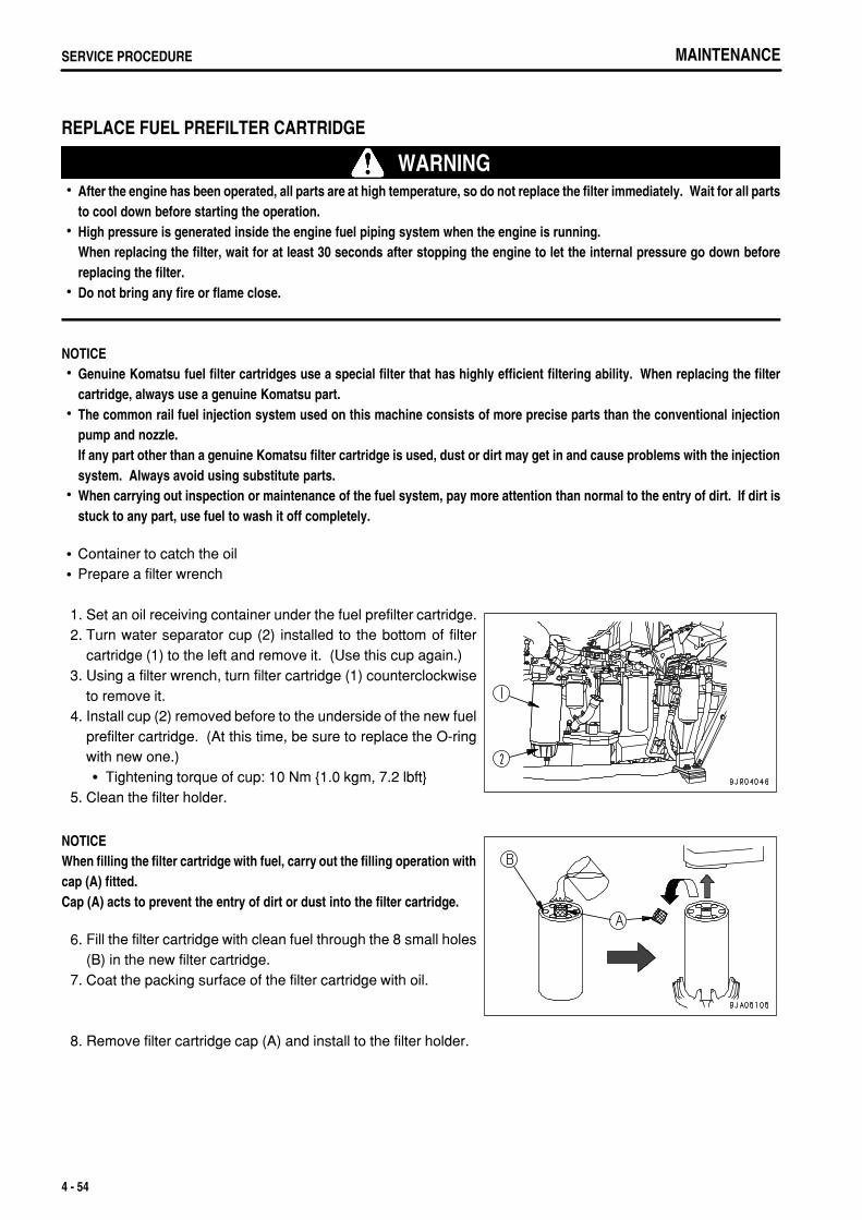
.
MAINTENANCESERVICE PROCEDURE
REPLACE FUEL PREFILTER CARTRIDGE
WARNINGAfter the engine has been operated, all parts are at high temperature, so do not replace the filter immediately. Wait for all partsto cool down before starting the operation.High pressure is generated inside the engine fuel piping system when the engine is running.When replacing the filter, wait for at least 30 seconds after stopping the engine to let the internal pressure go down beforereplacing the filter.Do not bring any fire or flame close.
NOTICEGenuine Komatsu fuel filter cartridges use a special filter that has highly efficient filtering ability. When replacing the filtercartridge, always use a genuine Komatsu part. The common rail fuel injection system used on this machine consists of more precise parts than the conventional injectionpump and nozzle. If any part other than a genuine Komatsu filter cartridge is used, dust or dirt may get in and cause problems with the injectionsystem. Always avoid using substitute parts.When carrying out inspection or maintenance of the fuel system, pay more attention than normal to the entry of dirt. If dirt isstuck to any part, use fuel to wash it off completely.
Container to catch the oilPrepare a filter wrench
1. Set an oil receiving container under the fuel prefilter cartridge. 2. Turn water separator cup (2) installed to the bottom of filter
cartridge (1) to the left and remove it. (Use this cup again.) 3. Using a filter wrench, turn filter cartridge (1) counterclockwise
to remove it. 4. Install cup (2) removed before to the underside of the new fuel
prefilter cartridge. (At this time, be sure to replace the O-ringwith new one.)
Tightening torque of cup: 10 Nm {1.0 kgm, 7.2 lbft} 5. Clean the filter holder.
NOTICEWhen filling the filter cartridge with fuel, carry out the filling operation withcap (A) fitted.Cap (A) acts to prevent the entry of dirt or dust into the filter cartridge.
6. Fill the filter cartridge with clean fuel through the 8 small holes(B) in the new filter cartridge.
7. Coat the packing surface of the filter cartridge with oil.
8. Remove filter cartridge cap (A) and install to the filter holder.
4 - 54
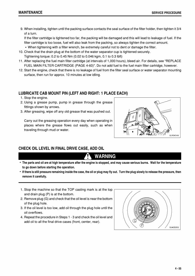
.
MAINTENANCE SERVICE PROCEDURE
9. When installing, tighten until the packing surface contacts the seal surface of the filter holder, then tighten it 3/4of a turn.If the filter cartridge is tightened too far, the packing will be damaged and this will lead to leakage of fuel. If thefilter cartridge is too loose, fuel will also leak from the packing, so always tighten the correct amount.
When tightening with a filter wrench, be extremely careful not to dent or damage the filter.10. Check that the drain plug at the bottom of the water separator cup is tightened securely.
Tightening torque: 0.2 to 0.45 Nm (0.02 to 0.046 kgm, 0.1 to 0.3 lbft)11. After replacing the fuel main filter cartridge (at intervals of 1,000 hours), bleed air. For details, see "REPLACE
FUEL MAIN FILTER CARTRIDGE (PAGE 4-60)". Do not add fuel to the fuel main filter cartridge, however.12. Start the engine, check that there is no leakage of fuel from the filter seal surface or water separator mounting
surface, then run for approx. 10 minutes at low idling.
LUBRICATE CAB MOUNT PIN (LEFT AND RIGHT: 1 PLACE EACH) 1. Stop the engine. 2. Using a grease pump, pump in grease through the grease
fittings shown by arrows. 3. After greasing, wipe off any old grease that was pushed out.
Carry out the greasing operation every day when operating inplaces where the grease flows out easily, such as whentraveling through mud or water.
CHECK OIL LEVEL IN FINAL DRIVE CASE, ADD OIL
WARNINGThe parts and oil are at high temperature after the engine is stopped, and may cause serious burns. Wait for the temperatureto go down before starting the operation.If there is still pressure remaining inside the case, the oil or plug may fly out. Turn the plug slowly to release the pressure, thenremove it carefully.
1. Stop the machine so that the TOP casting mark is at the topand drain plug (P) is at the bottom.
2. Remove plug (G) and check that the oil level is near the bottomof the plug hole.
3. If the oil level is too low, add oil through the plug hole until theoil overflows.
4. Repeat the procedure in Steps 1 - 3 and check the oil level andadd oil to all the final drive cases (front, center, rear).
4 - 55
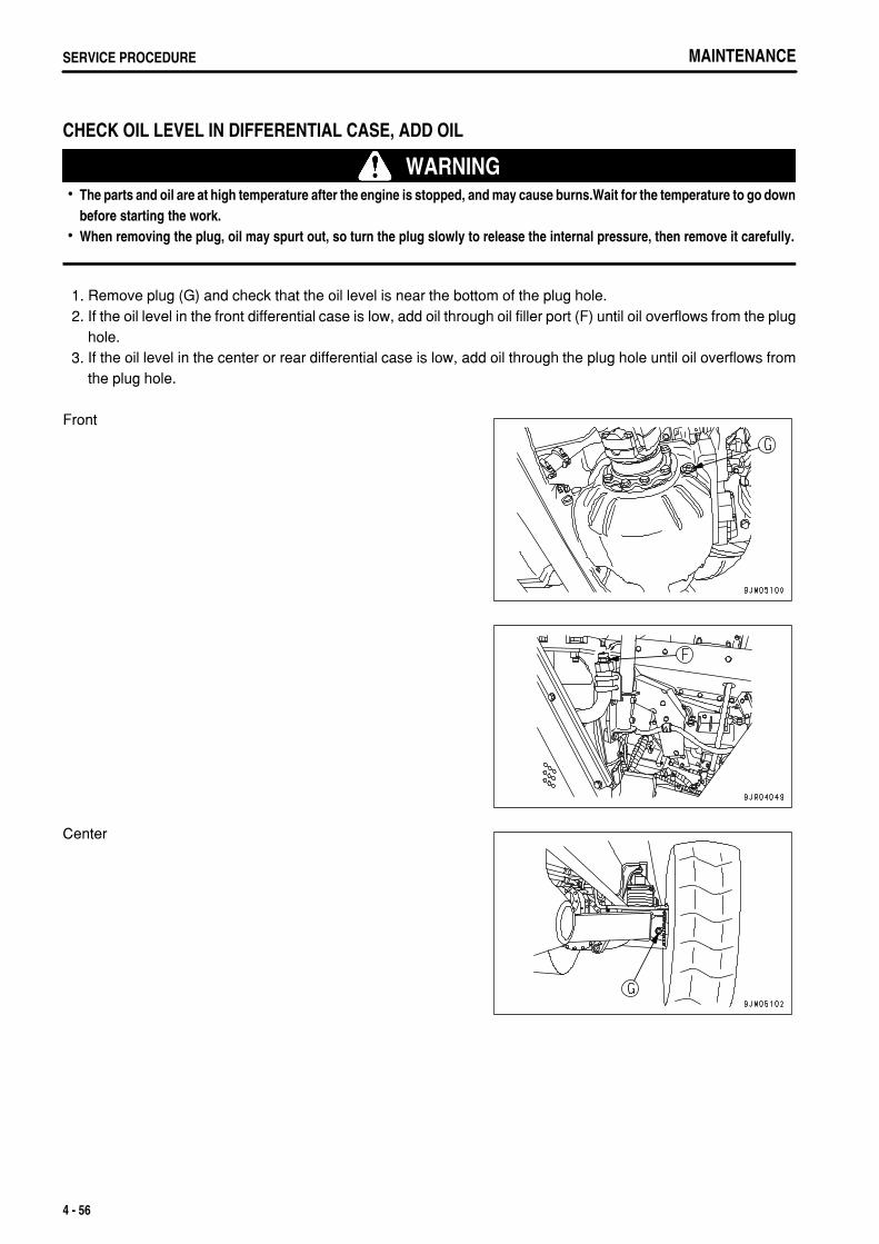
.
MAINTENANCESERVICE PROCEDURE
CHECK OIL LEVEL IN DIFFERENTIAL CASE, ADD OIL
WARNINGThe parts and oil are at high temperature after the engine is stopped, and may cause burns.Wait for the temperature to go downbefore starting the work.When removing the plug, oil may spurt out, so turn the plug slowly to release the internal pressure, then remove it carefully.
1. Remove plug (G) and check that the oil level is near the bottom of the plug hole. 2. If the oil level in the front differential case is low, add oil through oil filler port (F) until oil overflows from the plug
hole. 3. If the oil level in the center or rear differential case is low, add oil through the plug hole until oil overflows from
the plug hole.
Front
Center
4 - 56
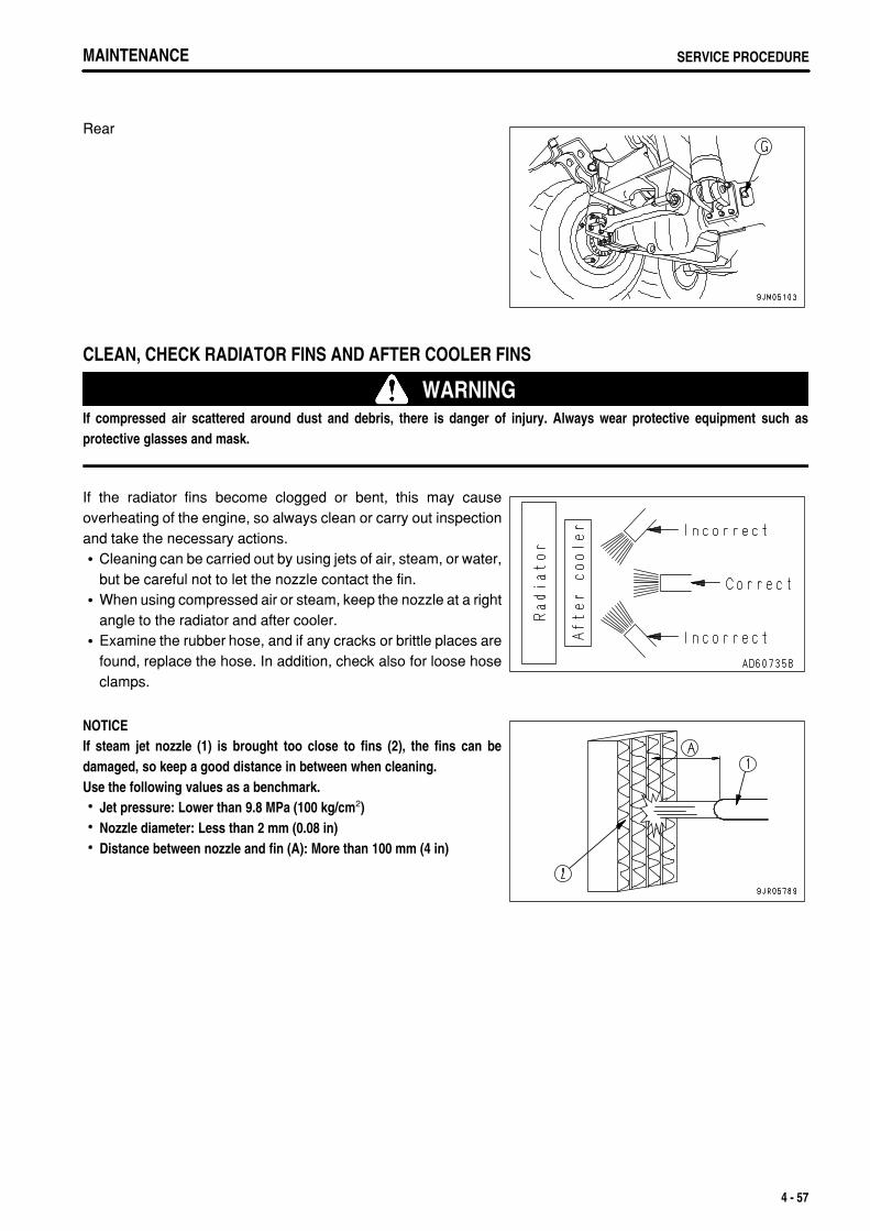
.
MAINTENANCE SERVICE PROCEDUREMAINTENANCE SERVICE PROCEDURE
Rear
CLEAN, CHECK RADIATOR FINS AND AFTER COOLER FINS
WARNINGIf compressed air scattered around dust and debris, there is danger of injury. Always wear protective equipment such asprotective glasses and mask.
If the radiator fins become clogged or bent, this may causeoverheating of the engine, so always clean or carry out inspectionand take the necessary actions.
Cleaning can be carried out by using jets of air, steam, or water,but be careful not to let the nozzle contact the fin.When using compressed air or steam, keep the nozzle at a rightangle to the radiator and after cooler.Examine the rubber hose, and if any cracks or brittle places arefound, replace the hose. In addition, check also for loose hoseclamps.
NOTICEIf steam jet nozzle (1) is brought too close to fins (2), the fins can bedamaged, so keep a good distance in between when cleaning.Use the following values as a benchmark.
Jet pressure: Lower than 9.8 MPa (100 kg/cm2)Nozzle diameter: Less than 2 mm (0.08 in)Distance between nozzle and fin (A): More than 100 mm (4 in)
4 - 57
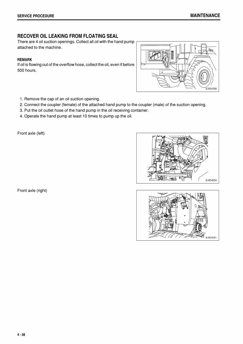
.
MAINTENANCESERVICE PROCEDURE
RECOVER OIL LEAKING FROM FLOATING SEALThere are 4 oil suction openings. Collect all oil with the hand pumpattached to the machine.
REMARKIf oil is flowing out of the overflow hose, collect the oil, even if before500 hours.
1. Remove the cap of an oil suction opening. 2. Connect the coupler (female) of the attached hand pump to the coupler (male) of the suction opening. 3. Put the oil outlet hose of the hand pump in the oil receiving container. 4. Operate the hand pump at least 10 times to pump up the oil.
Front axle (left)
Front axle (right)
4 - 58
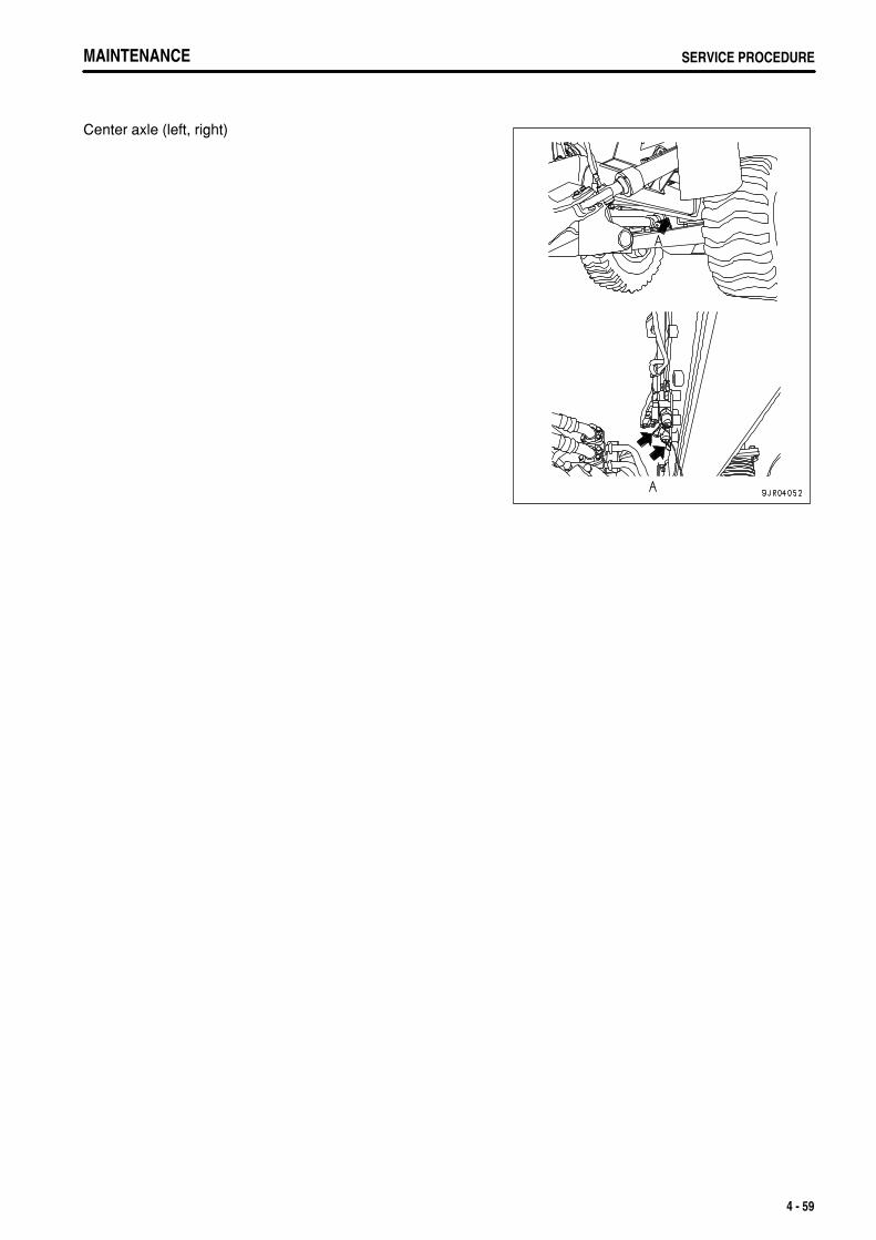
.
MAINTENANCE SERVICE PROCEDUREMAINTENANCE SERVICE PROCEDURE
Center axle (left, right)
4 - 59
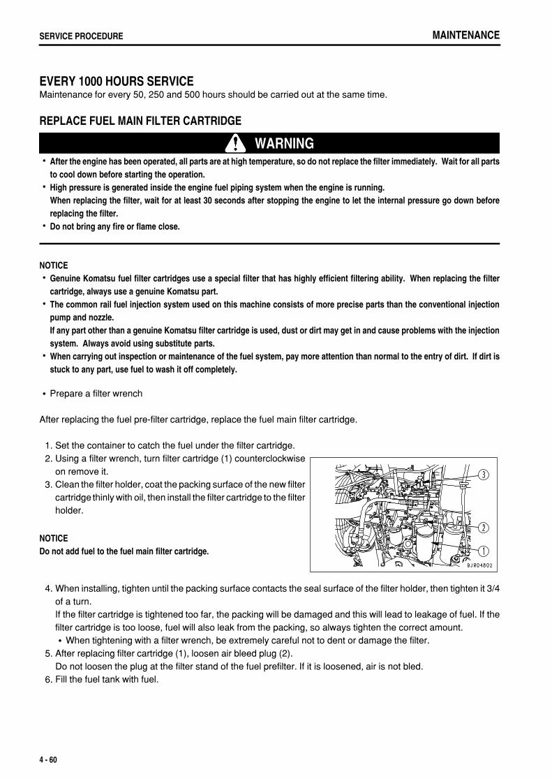
.
MAINTENANCESERVICE PROCEDURE
EVERY 1000 HOURS SERVICEMaintenance for every 50, 250 and 500 hours should be carried out at the same time.
REPLACE FUEL MAIN FILTER CARTRIDGE
WARNINGAfter the engine has been operated, all parts are at high temperature, so do not replace the filter immediately. Wait for all partsto cool down before starting the operation.High pressure is generated inside the engine fuel piping system when the engine is running.When replacing the filter, wait for at least 30 seconds after stopping the engine to let the internal pressure go down beforereplacing the filter.Do not bring any fire or flame close.
NOTICEGenuine Komatsu fuel filter cartridges use a special filter that has highly efficient filtering ability. When replacing the filtercartridge, always use a genuine Komatsu part. The common rail fuel injection system used on this machine consists of more precise parts than the conventional injectionpump and nozzle. If any part other than a genuine Komatsu filter cartridge is used, dust or dirt may get in and cause problems with the injectionsystem. Always avoid using substitute parts.When carrying out inspection or maintenance of the fuel system, pay more attention than normal to the entry of dirt. If dirt isstuck to any part, use fuel to wash it off completely.
Prepare a filter wrench
After replacing the fuel pre-filter cartridge, replace the fuel main filter cartridge.
1. Set the container to catch the fuel under the filter cartridge. 2. Using a filter wrench, turn filter cartridge (1) counterclockwise
on remove it. 3. Clean the filter holder, coat the packing surface of the new filter
cartridge thinly with oil, then install the filter cartridge to the filterholder.
NOTICEDo not add fuel to the fuel main filter cartridge.
4. When installing, tighten until the packing surface contacts the seal surface of the filter holder, then tighten it 3/4of a turn.If the filter cartridge is tightened too far, the packing will be damaged and this will lead to leakage of fuel. If thefilter cartridge is too loose, fuel will also leak from the packing, so always tighten the correct amount.
When tightening with a filter wrench, be extremely careful not to dent or damage the filter. 5. After replacing filter cartridge (1), loosen air bleed plug (2).
Do not loosen the plug at the filter stand of the fuel prefilter. If it is loosened, air is not bled. 6. Fill the fuel tank with fuel.
4 - 60
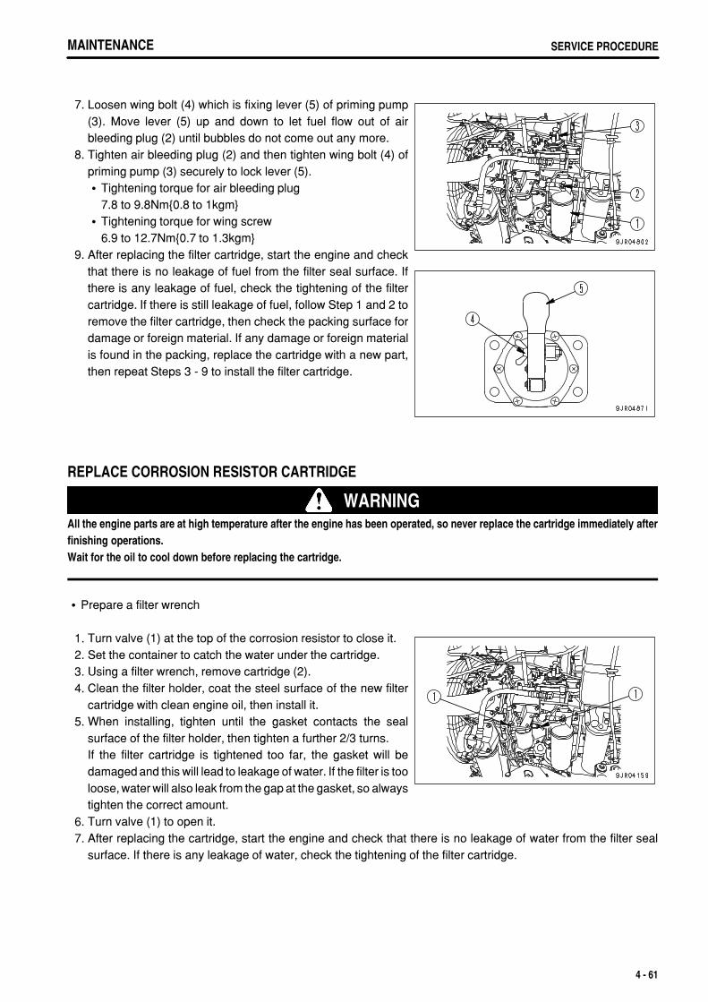
.
MAINTENANCE SERVICE PROCEDUREMAINTENANCE SERVICE PROCEDURE
7. Loosen wing bolt (4) which is fixing lever (5) of priming pump(3). Move lever (5) up and down to let fuel flow out of airbleeding plug (2) until bubbles do not come out any more.
8. Tighten air bleeding plug (2) and then tighten wing bolt (4) ofpriming pump (3) securely to lock lever (5).
Tightening torque for air bleeding plug7.8 to 9.8Nm{0.8 to 1kgm}Tightening torque for wing screw6.9 to 12.7Nm{0.7 to 1.3kgm}
9. After replacing the filter cartridge, start the engine and checkthat there is no leakage of fuel from the filter seal surface. Ifthere is any leakage of fuel, check the tightening of the filtercartridge. If there is still leakage of fuel, follow Step 1 and 2 toremove the filter cartridge, then check the packing surface fordamage or foreign material. If any damage or foreign materialis found in the packing, replace the cartridge with a new part,then repeat Steps 3 - 9 to install the filter cartridge.
REPLACE CORROSION RESISTOR CARTRIDGE
WARNINGAll the engine parts are at high temperature after the engine has been operated, so never replace the cartridge immediately afterfinishing operations.Wait for the oil to cool down before replacing the cartridge.
Prepare a filter wrench
1. Turn valve (1) at the top of the corrosion resistor to close it. 2. Set the container to catch the water under the cartridge. 3. Using a filter wrench, remove cartridge (2). 4. Clean the filter holder, coat the steel surface of the new filter
cartridge with clean engine oil, then install it. 5. When installing, tighten until the gasket contacts the seal
surface of the filter holder, then tighten a further 2/3 turns.If the filter cartridge is tightened too far, the gasket will bedamaged and this will lead to leakage of water. If the filter is tooloose, water will also leak from the gap at the gasket, so alwaystighten the correct amount.
6. Turn valve (1) to open it. 7. After replacing the cartridge, start the engine and check that there is no leakage of water from the filter seal
surface. If there is any leakage of water, check the tightening of the filter cartridge.
4 - 61
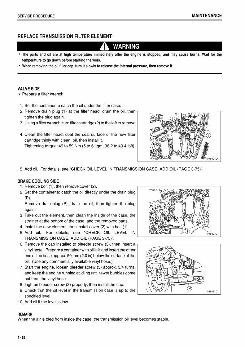
.
MAINTENANCESERVICE PROCEDURE
REPLACE TRANSMISSION FILTER ELEMENT
WARNINGThe parts and oil are at high temperature immediately after the engine is stopped, and may cause burns. Wait for thetemperature to go down before starting the work.When removing the oil filler cap, turn it slowly to release the internal pressure, then remove it.
VALVE SIDEPrepare a filter wrench
1. Set the container to catch the oil under the filter case. 2. Remove drain plug (1) at the filter head, drain the oil, then
tighten the plug again. 3. Using a filter wrench, turn filter cartridge (2) to the left to remove
it. 4. Clean the filter head, coat the seal surface of the new filter
cartridge thinly with clean oil, then install it.Tightening torque: 49 to 59 Nm (5 to 6 kgm, 36.2 to 43.4 lbft)
5. Add oil. For details, see "CHECK OIL LEVEL IN TRANSMISSION CASE, ADD OIL (PAGE 3-75)".
BRAKE COOLING SIDE 1. Remove bolt (1), then remove cover (2). 2. Set the container to catch the oil directly under the drain plug
(P).Remove drain plug (P), drain the oil, then tighten the plugagain.
3. Take out the element, then clean the inside of the case, thestrainer at the bottom of the case, and the removed parts.
4. Install the new element, then install cover (2) with bolt (1). 5. Add oil. For details, see "CHECK OIL LEVEL IN
TRANSMISSION CASE, ADD OIL (PAGE 3-75)". 6. Remove the cap installed to bleeder screw (3), then insert a
vinyl hose. Prepare a container with oil in it and insert the otherend of the hose approx. 50 mm (2.0 in) below the surface of theoil. (Use any commercially available vinyl hose.)
7. Start the engine, loosen bleeder screw (3) approx. 3/4 turns,and keep the engine running at idling until fewer bubbles comeout from the vinyl hose.
8. Tighten bleeder screw (3) properly, then install the cap. 9. Check that the oil level in the transmission case is up to the
specified level.10. Add oil if the level is low.
REMARKWhen the air is bled from inside the case, the transmission oil level becomes stable.
4 - 62
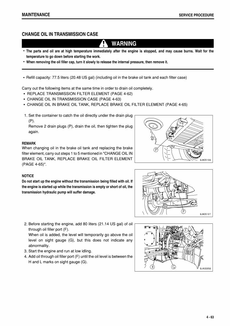
.
MAINTENANCE SERVICE PROCEDURE
CHANGE OIL IN TRANSMISSION CASE
WARNINGThe parts and oil are at high temperature immediately after the engine is stopped, and may cause burns. Wait for thetemperature to go down before starting the work.When removing the oil filler cap, turn it slowly to release the internal pressure, then remove it.
Refill capacity: 77.5 liters (20.48 US gal) (including oil in the brake oil tank and each filter case)
Carry out the following items at the same time in order to drain oil completely.REPLACE TRANSMISSION FILTER ELEMENT (PAGE 4-62)CHANGE OIL IN TRANSMISSION CASE (PAGE 4-63)CHANGE OIL IN BRAKE OIL TANK, REPLACE BRAKE OIL FILTER ELEMENT (PAGE 4-65)
1. Set the container to catch the oil directly under the drain plug(P).Remove 2 drain plugs (P), drain the oil, then tighten the plugagain.
REMARKWhen changing oil in the brake oil tank and replacing the brakefilter element, carry out steps 1 to 5 mentioned in "CHANGE OIL INBRAKE OIL TANK, REPLACE BRAKE OIL FILTER ELEMENT(PAGE 4-65)".
NOTICEDo not start up the engine without the transmission being filled with oil. Ifthe engine is started up while the transmission is empty or short of oil, thetransmission hydraulic pump will suffer damage.
2. Before starting the engine, add 80 liters (21.14 US gal) of oilthrough oil filler port (F).When oil is added, the level will temporarily go above the oillevel on sight gauge (G), but this does not indicate anyabnormality.
3. Start the engine and run at low idling. 4. Add oil through oil filler port (F) until the oil level is between the
H and L marks on sight gauge (G).
4 - 63
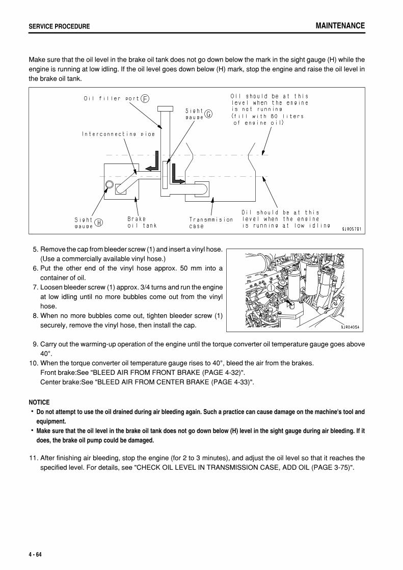
.
MAINTENANCESERVICE PROCEDURE
Make sure that the oil level in the brake oil tank does not go down below the mark in the sight gauge (H) while theengine is running at low idling. If the oil level goes down below (H) mark, stop the engine and raise the oil level inthe brake oil tank.
5. Remove the cap from bleeder screw (1) and insert a vinyl hose.(Use a commercially available vinyl hose.)
6. Put the other end of the vinyl hose approx. 50 mm into acontainer of oil.
7. Loosen bleeder screw (1) approx. 3/4 turns and run the engineat low idling until no more bubbles come out from the vinylhose.
8. When no more bubbles come out, tighten bleeder screw (1)securely, remove the vinyl hose, then install the cap.
9. Carry out the warming-up operation of the engine until the torque converter oil temperature gauge goes above40°.
10. When the torque converter oil temperature gauge rises to 40°, bleed the air from the brakes.Front brake:See "BLEED AIR FROM FRONT BRAKE (PAGE 4-32)".Center brake:See "BLEED AIR FROM CENTER BRAKE (PAGE 4-33)".
NOTICEDo not attempt to use the oil drained during air bleeding again. Such a practice can cause damage on the machine's tool andequipment.Make sure that the oil level in the brake oil tank does not go down below (H) level in the sight gauge during air bleeding. If itdoes, the brake oil pump could be damaged.
11. After finishing air bleeding, stop the engine (for 2 to 3 minutes), and adjust the oil level so that it reaches thespecified level. For details, see "CHECK OIL LEVEL IN TRANSMISSION CASE, ADD OIL (PAGE 3-75)".
4 - 64
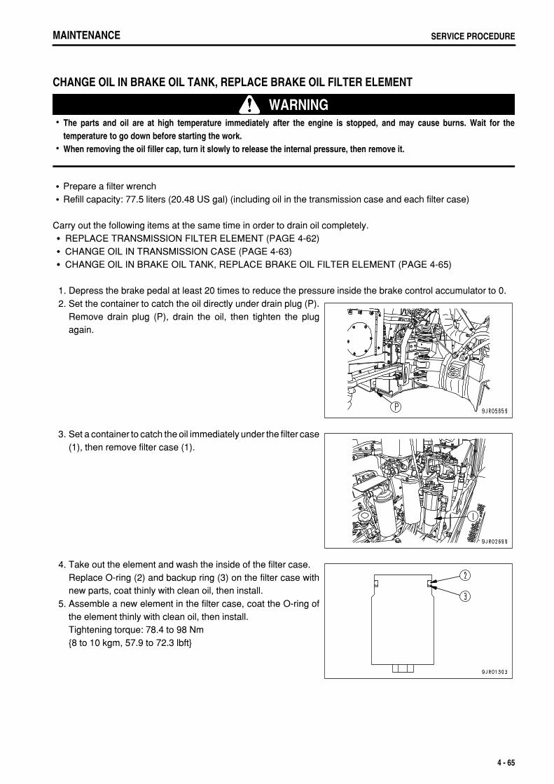
.
MAINTENANCE SERVICE PROCEDURE
CHANGE OIL IN BRAKE OIL TANK, REPLACE BRAKE OIL FILTER ELEMENT
WARNINGThe parts and oil are at high temperature immediately after the engine is stopped, and may cause burns. Wait for thetemperature to go down before starting the work.When removing the oil filler cap, turn it slowly to release the internal pressure, then remove it.
Prepare a filter wrenchRefill capacity: 77.5 liters (20.48 US gal) (including oil in the transmission case and each filter case)
Carry out the following items at the same time in order to drain oil completely.REPLACE TRANSMISSION FILTER ELEMENT (PAGE 4-62)CHANGE OIL IN TRANSMISSION CASE (PAGE 4-63)CHANGE OIL IN BRAKE OIL TANK, REPLACE BRAKE OIL FILTER ELEMENT (PAGE 4-65)
1. Depress the brake pedal at least 20 times to reduce the pressure inside the brake control accumulator to 0. 2. Set the container to catch the oil directly under drain plug (P).
Remove drain plug (P), drain the oil, then tighten the plugagain.
3. Set a container to catch the oil immediately under the filter case(1), then remove filter case (1).
4. Take out the element and wash the inside of the filter case.Replace O-ring (2) and backup ring (3) on the filter case withnew parts, coat thinly with clean oil, then install.
5. Assemble a new element in the filter case, coat the O-ring ofthe element thinly with clean oil, then install.Tightening torque: 78.4 to 98 Nm{8 to 10 kgm, 57.9 to 72.3 lbft}
4 - 65
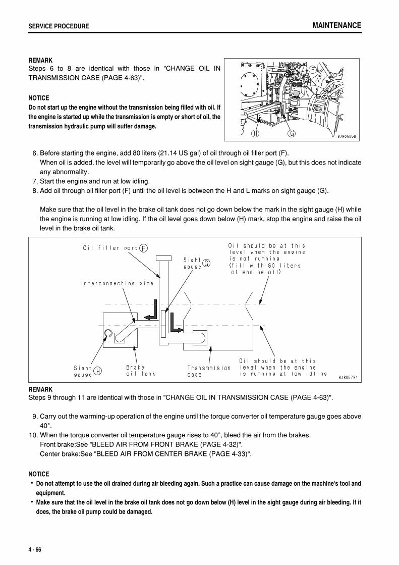
.
MAINTENANCESERVICE PROCEDURE MAINTENANCESERVICE PROCEDURE
REMARKSteps 6 to 8 are identical with those in "CHANGE OIL INTRANSMISSION CASE (PAGE 4-63)".
NOTICEDo not start up the engine without the transmission being filled with oil. Ifthe engine is started up while the transmission is empty or short of oil, thetransmission hydraulic pump will suffer damage.
6. Before starting the engine, add 80 liters (21.14 US gal) of oil through oil filler port (F).When oil is added, the level will temporarily go above the oil level on sight gauge (G), but this does not indicateany abnormality.
7. Start the engine and run at low idling. 8. Add oil through oil filler port (F) until the oil level is between the H and L marks on sight gauge (G).
Make sure that the oil level in the brake oil tank does not go down below the mark in the sight gauge (H) whilethe engine is running at low idling. If the oil level goes down below (H) mark, stop the engine and raise the oillevel in the brake oil tank.
REMARKSteps 9 through 11 are identical with those in "CHANGE OIL IN TRANSMISSION CASE (PAGE 4-63)".
9. Carry out the warming-up operation of the engine until the torque converter oil temperature gauge goes above40°.
10. When the torque converter oil temperature gauge rises to 40°, bleed the air from the brakes.Front brake:See "BLEED AIR FROM FRONT BRAKE (PAGE 4-32)".Center brake:See "BLEED AIR FROM CENTER BRAKE (PAGE 4-33)".
NOTICEDo not attempt to use the oil drained during air bleeding again. Such a practice can cause damage on the machine's tool andequipment.Make sure that the oil level in the brake oil tank does not go down below (H) level in the sight gauge during air bleeding. If itdoes, the brake oil pump could be damaged.
4 - 66

.
MAINTENANCE SERVICE PROCEDURE
11. After finishing air bleeding, stop the engine (for 2 to 3 minutes), and adjust the oil level so that it reaches thespecified level. For details, see "CHECK OIL LEVEL IN TRANSMISSION CASE, ADD OIL (PAGE 3-75)".
4 - 67
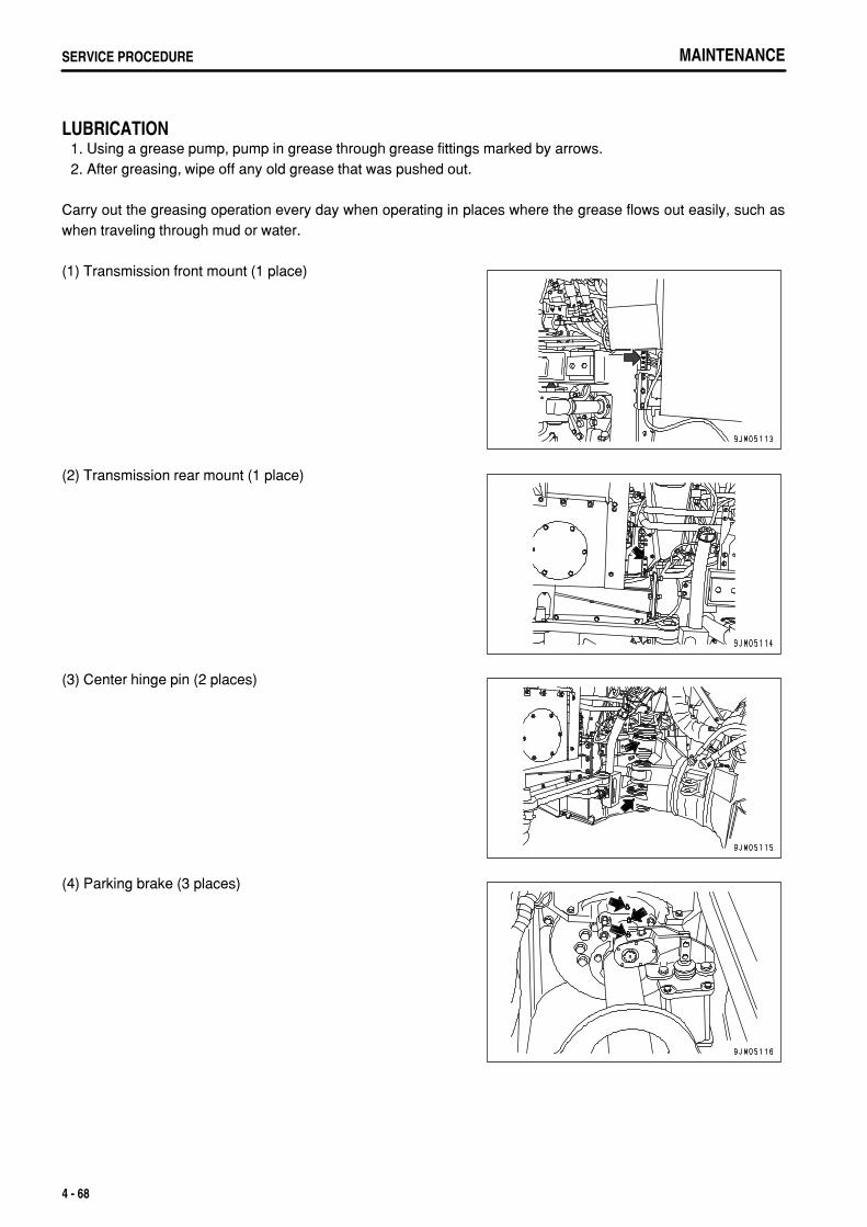
.
MAINTENANCESERVICE PROCEDURE
LUBRICATION 1. Using a grease pump, pump in grease through grease fittings marked by arrows. 2. After greasing, wipe off any old grease that was pushed out.
Carry out the greasing operation every day when operating in places where the grease flows out easily, such aswhen traveling through mud or water.
(1) Transmission front mount (1 place)
(2) Transmission rear mount (1 place)
(3) Center hinge pin (2 places)
(4) Parking brake (3 places)
4 - 68

.
MAINTENANCE SERVICE PROCEDURE
CHECK WEAR OF BRAKE DISC
WARNINGCarry out this check when the brake oil temperature is below 60°C (140°F).If the disc wear approaches the wear limit, check the condition frequently, regardless of the maintenance interval. In addition,check the retarder capacity carefully.
1. Stop the machine on level ground, set the parking brake switch to the PARKING position, then check that theother brakes are not applied before starting inspection.
2. Turn the starting switch ON and check that the retarder oil pressure caution lamp is out.If the retarder oil pressure caution lamp is lighted up, start the engine, run the engine at 2000 rpm, and if the lampgoes out, turn the starting switch OFF.
3. Remove cap nut (1).
4. Depress the brake pedal, keep it depressed, and push in therod (2) of the gauge until contacts the piston.
5. If mark (3) at position "A" of rod (2) enters beyond guide endface (4), it means that the disc has reached the wear limit.For the front brake, use the mark at position "A", and for thecenter brake, use the mark at position "B".If the disc has reached the wear limit, please contact yourKomatsu distributor for inspection and maintenance.
6. Tighten cap nut (1) removed in Step 3.Tightening torque: 14.7 to 19.6 Nm
(1.5 to 2.0 kgm, 10.8 to 14.5 lbft)
REMARKWith new machines, the position of the guide is adjusted so that mark (5) comes to end face (4) of the guide, sodo not loosen locknut (6) except when replacing the disc.Carry out the operation with two workers. One worker depresses the brake pedal and the other pushes in therod.If the rod is pushed in when the engine is running, the rod will be pushed back by the brake cooling oil pressure,so always carry out this operation with the engine stopped.There are marks on the rod at three places (A, B, C), but for the front brake, use the mark at position "A", and forthe center brake, use the mark at position "B".
4 - 69
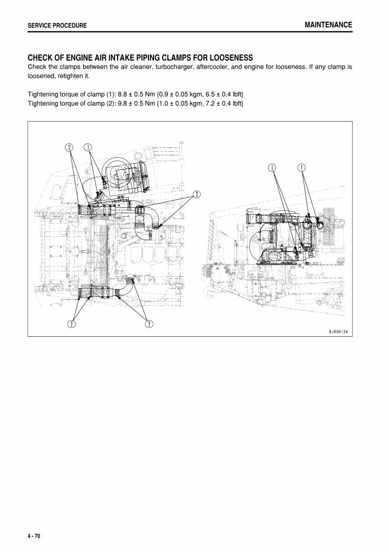
.
MAINTENANCESERVICE PROCEDURE
CHECK OF ENGINE AIR INTAKE PIPING CLAMPS FOR LOOSENESSCheck the clamps between the air cleaner, turbocharger, aftercooler, and engine for looseness. If any clamp isloosened, retighten it.
Tightening torque of clamp (1): 8.8 ± 0.5 Nm {0.9 ± 0.05 kgm, 6.5 ± 0.4 lbft}Tightening torque of clamp (2): 9.8 ± 0.5 Nm {1.0 ± 0.05 kgm, 7.2 ± 0.4 lbft}
4 - 70
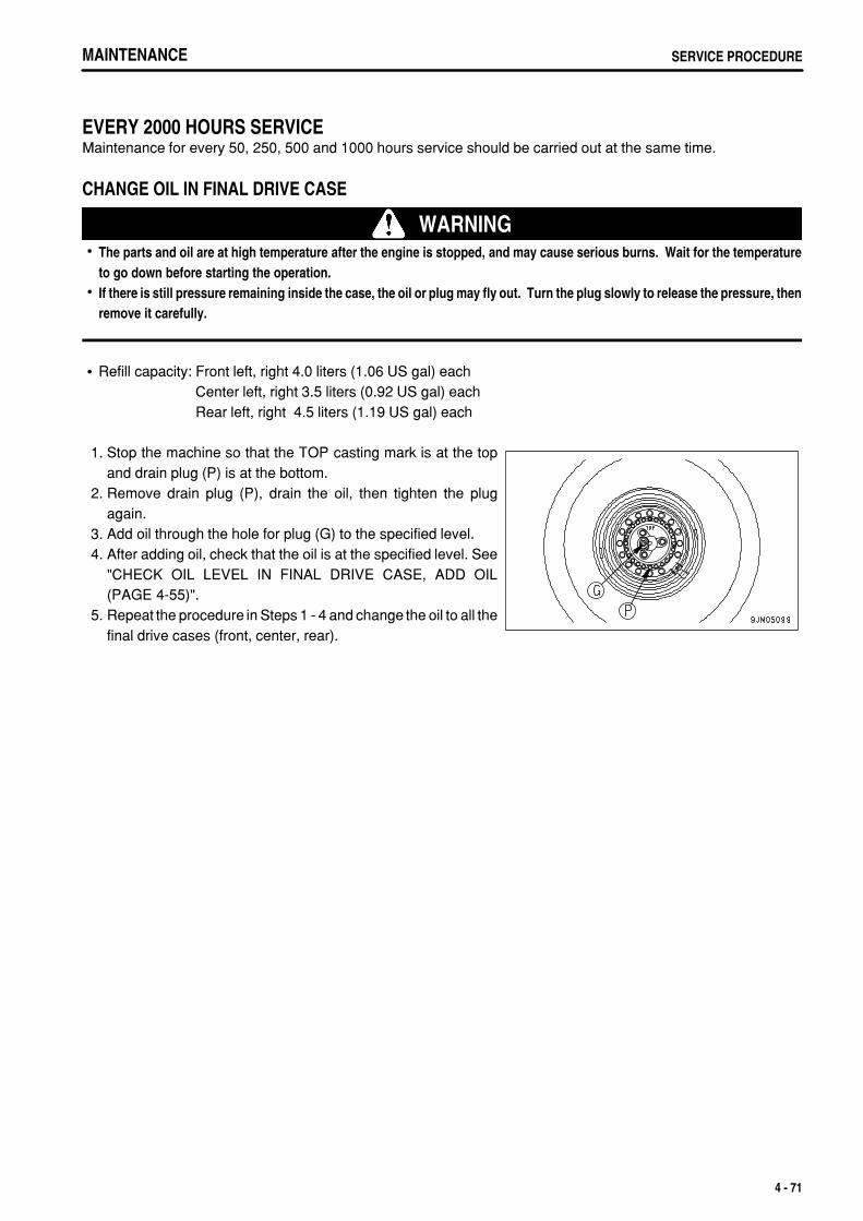
.
MAINTENANCE SERVICE PROCEDURE
EVERY 2000 HOURS SERVICEMaintenance for every 50, 250, 500 and 1000 hours service should be carried out at the same time.
CHANGE OIL IN FINAL DRIVE CASE
WARNINGThe parts and oil are at high temperature after the engine is stopped, and may cause serious burns. Wait for the temperatureto go down before starting the operation.If there is still pressure remaining inside the case, the oil or plug may fly out. Turn the plug slowly to release the pressure, thenremove it carefully.
Refill capacity: Front left, right 4.0 liters (1.06 US gal) eachCenter left, right 3.5 liters (0.92 US gal) eachRear left, right 4.5 liters (1.19 US gal) each
1. Stop the machine so that the TOP casting mark is at the topand drain plug (P) is at the bottom.
2. Remove drain plug (P), drain the oil, then tighten the plugagain.
3. Add oil through the hole for plug (G) to the specified level. 4. After adding oil, check that the oil is at the specified level. See
"CHECK OIL LEVEL IN FINAL DRIVE CASE, ADD OIL(PAGE 4-55)".
5. Repeat the procedure in Steps 1 - 4 and change the oil to all thefinal drive cases (front, center, rear).
4 - 71
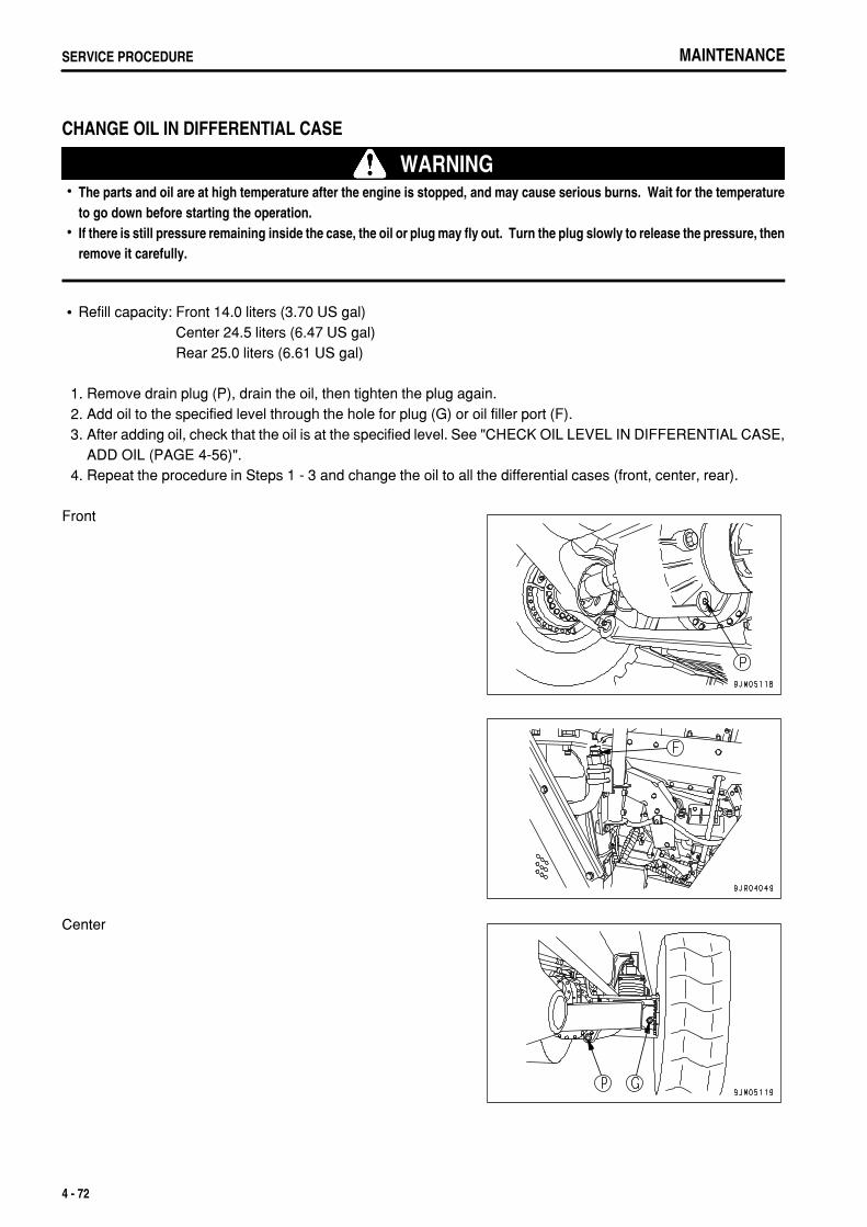
.
MAINTENANCESERVICE PROCEDURE
CHANGE OIL IN DIFFERENTIAL CASE
WARNINGThe parts and oil are at high temperature after the engine is stopped, and may cause serious burns. Wait for the temperatureto go down before starting the operation.If there is still pressure remaining inside the case, the oil or plug may fly out. Turn the plug slowly to release the pressure, thenremove it carefully.
Refill capacity: Front 14.0 liters (3.70 US gal)Center 24.5 liters (6.47 US gal)Rear 25.0 liters (6.61 US gal)
1. Remove drain plug (P), drain the oil, then tighten the plug again. 2. Add oil to the specified level through the hole for plug (G) or oil filler port (F). 3. After adding oil, check that the oil is at the specified level. See "CHECK OIL LEVEL IN DIFFERENTIAL CASE,
ADD OIL (PAGE 4-56)". 4. Repeat the procedure in Steps 1 - 3 and change the oil to all the differential cases (front, center, rear).
Front
Center
4 - 72
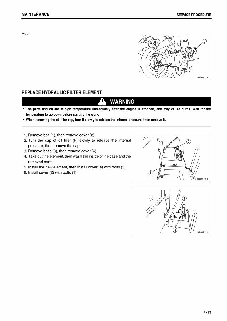
.
MAINTENANCE SERVICE PROCEDUREMAINTENANCE SERVICE PROCEDURE
Rear
REPLACE HYDRAULIC FILTER ELEMENT
WARNINGThe parts and oil are at high temperature immediately after the engine is stopped, and may cause burns. Wait for thetemperature to go down before starting the work.When removing the oil filler cap, turn it slowly to release the internal pressure, then remove it.
1. Remove bolt (1), then remove cover (2). 2. Turn the cap of oil filler (F) slowly to release the internal
pressure, then remove the cap. 3. Remove bolts (3), then remove cover (4). 4. Take out the element, then wash the inside of the case and the
removed parts. 5. Install the new element, then install cover (4) with bolts (3). 6. Install cover (2) with bolts (1).
4 - 73

.
MAINTENANCESERVICE PROCEDURE
CLEAN TRANSMISSION CASE STRAINER
WARNINGThe parts and oil are at high temperature immediately after the engine is stopped, and may cause burns. Wait for thetemperature to go down before starting the work.When removing the oil filler cap, turn it slowly to release the internal pressure, then remove it.
Drain the oil from the transmission case before starting the operation. For details, see Section "CHANGE OIL INTRANSMISSION CASE (PAGE 4-63)". 1. Remove bolt (1), then remove cover (2) and take out the
strainer. 2. Remove any dirt stuck to the strainer, then wash in clean diesel
fuel or flushing oil. If the strainer is damaged, replace it. 3. Install the strainers in their original position.
CLEAN BREATHER
WARNINGThe parts and oil are at high temperature after the engine is stopped, and may cause serious burns. Wait for the temperatureto go down before cleaning the engine breather.When using compressed air, there is a hazard that dirt may be blown up and cause serious injury.Always use safety glasses, dust mask, or other protective equipment.
Remove the mud and dirt from around the breather, then remove the breather and wash out the dirt from inside withclean diesel oil or flushing oil.
Transmission
4 - 74
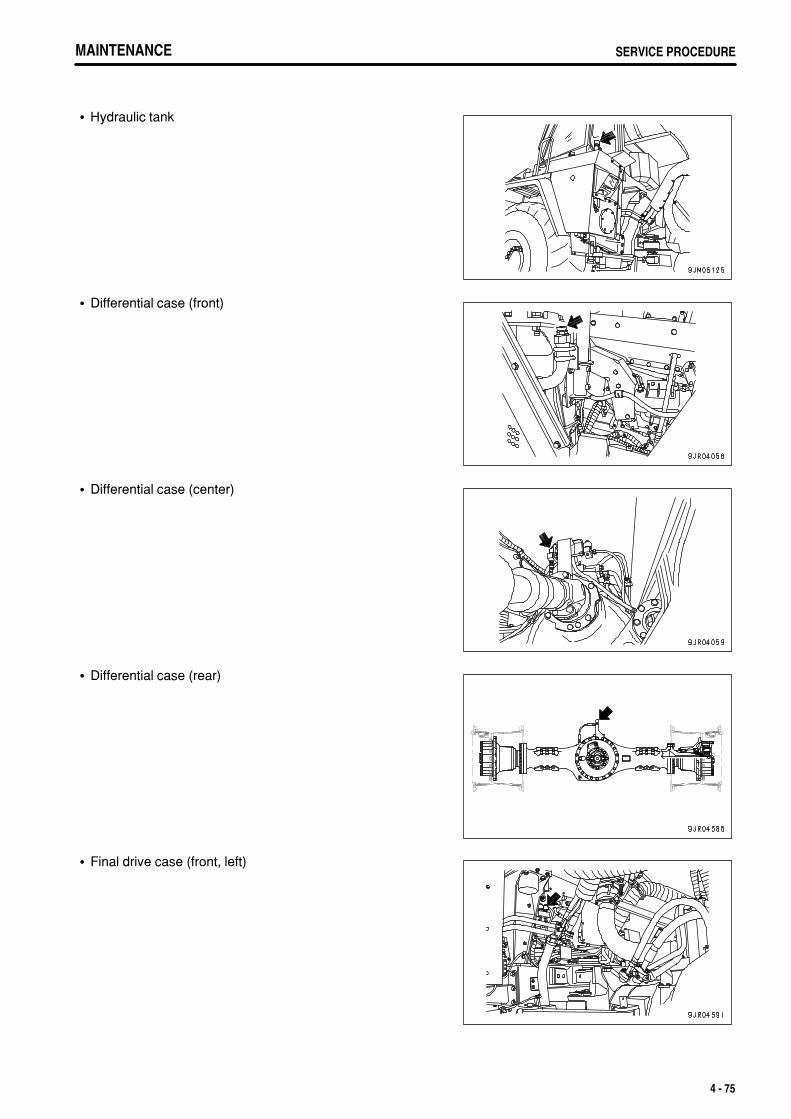
.
MAINTENANCE SERVICE PROCEDUREMAINTENANCE SERVICE PROCEDURE
Hydraulic tank
Differential case (front)
Differential case (center)
Differential case (rear)
Final drive case (front, left)
4 - 75
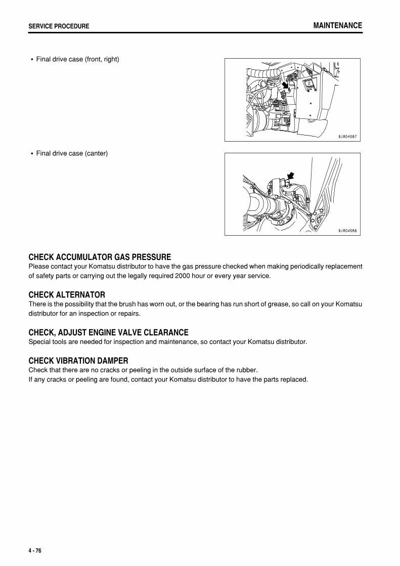
.
MAINTENANCESERVICE PROCEDURE MAINTENANCESERVICE PROCEDURE
Final drive case (front, right)
Final drive case (canter)
CHECK ACCUMULATOR GAS PRESSUREPlease contact your Komatsu distributor to have the gas pressure checked when making periodically replacementof safety parts or carrying out the legally required 2000 hour or every year service.
CHECK ALTERNATORThere is the possibility that the brush has worn out, or the bearing has run short of grease, so call on your Komatsudistributor for an inspection or repairs.
CHECK, ADJUST ENGINE VALVE CLEARANCESpecial tools are needed for inspection and maintenance, so contact your Komatsu distributor.
CHECK VIBRATION DAMPERCheck that there are no cracks or peeling in the outside surface of the rubber.If any cracks or peeling are found, contact your Komatsu distributor to have the parts replaced.
4 - 76
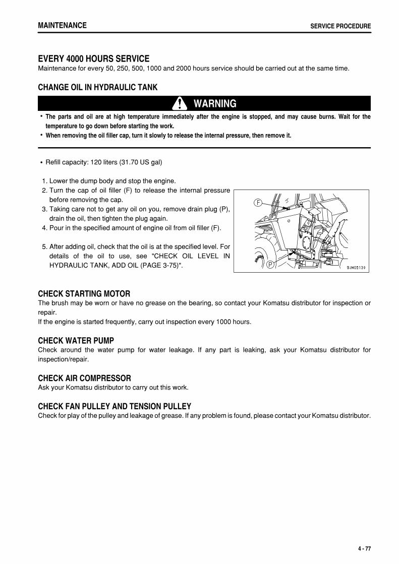
.
MAINTENANCE SERVICE PROCEDURE
EVERY 4000 HOURS SERVICEMaintenance for every 50, 250, 500, 1000 and 2000 hours service should be carried out at the same time.
CHANGE OIL IN HYDRAULIC TANK
WARNINGThe parts and oil are at high temperature immediately after the engine is stopped, and may cause burns. Wait for thetemperature to go down before starting the work.When removing the oil filler cap, turn it slowly to release the internal pressure, then remove it.
Refill capacity: 120 liters (31.70 US gal)
1. Lower the dump body and stop the engine. 2. Turn the cap of oil filler (F) to release the internal pressure
before removing the cap. 3. Taking care not to get any oil on you, remove drain plug (P),
drain the oil, then tighten the plug again. 4. Pour in the specified amount of engine oil from oil filler (F).
5. After adding oil, check that the oil is at the specified level. Fordetails of the oil to use, see "CHECK OIL LEVEL INHYDRAULIC TANK, ADD OIL (PAGE 3-75)".
CHECK STARTING MOTORThe brush may be worn or have no grease on the bearing, so contact your Komatsu distributor for inspection orrepair.If the engine is started frequently, carry out inspection every 1000 hours.
CHECK WATER PUMPCheck around the water pump for water leakage. If any part is leaking, ask your Komatsu distributor forinspection/repair.
CHECK AIR COMPRESSORAsk your Komatsu distributor to carry out this work.
CHECK FAN PULLEY AND TENSION PULLEYCheck for play of the pulley and leakage of grease. If any problem is found, please contact your Komatsu distributor.
4 - 77
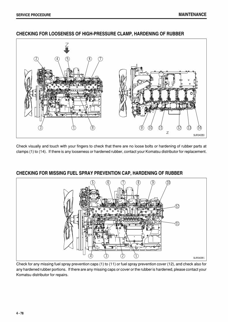
.
MAINTENANCESERVICE PROCEDURE
CHECKING FOR LOOSENESS OF HIGH-PRESSURE CLAMP, HARDENING OF RUBBER
Check visually and touch with your fingers to check that there are no loose bolts or hardening of rubber parts atclamps (1) to (14). If there is any looseness or hardened rubber, contact your Komatsu distributor for replacement.
CHECKING FOR MISSING FUEL SPRAY PREVENTION CAP, HARDENING OF RUBBER
Check for any missing fuel spray prevention caps (1) to (11) or fuel spray prevention cover (12), and check also forany hardened rubber portions. If there are any missing caps or cover or the rubber is hardened, please contact yourKomatsu distributor for repairs.
4 - 78
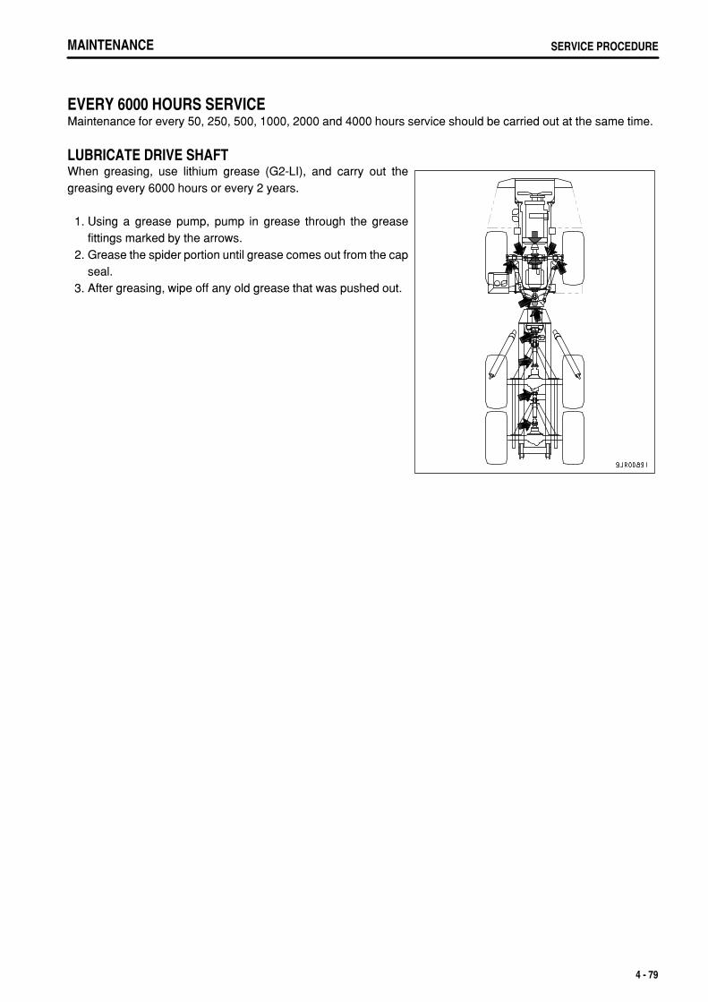
.
MAINTENANCE SERVICE PROCEDURE
EVERY 6000 HOURS SERVICEMaintenance for every 50, 250, 500, 1000, 2000 and 4000 hours service should be carried out at the same time.
LUBRICATE DRIVE SHAFTWhen greasing, use lithium grease (G2-LI), and carry out thegreasing every 6000 hours or every 2 years.
1. Using a grease pump, pump in grease through the greasefittings marked by the arrows.
2. Grease the spider portion until grease comes out from the capseal.
3. After greasing, wipe off any old grease that was pushed out.
4 - 79
.
MAINTENANCESERVICE PROCEDURE
EVERY 8000 HOURS SERVICEMaintenance for every 50, 250, 500, 1000, 2000, 4000 and 6000 hours service should be carried out at the sametime.
REPLACE HIGH-PRESSURE PIPING CLAMPAsk your Komatsu distributor to carry out this work.
REPLACE FUEL SPRAY PREVENTION CAPAsk your Komatsu distributor to carry out this work.
OVERHAUL STARTING MOTOR AND ALTERNATORAsk your Komatsu distributor to carry out this work.
4 - 80

.
5 - 1
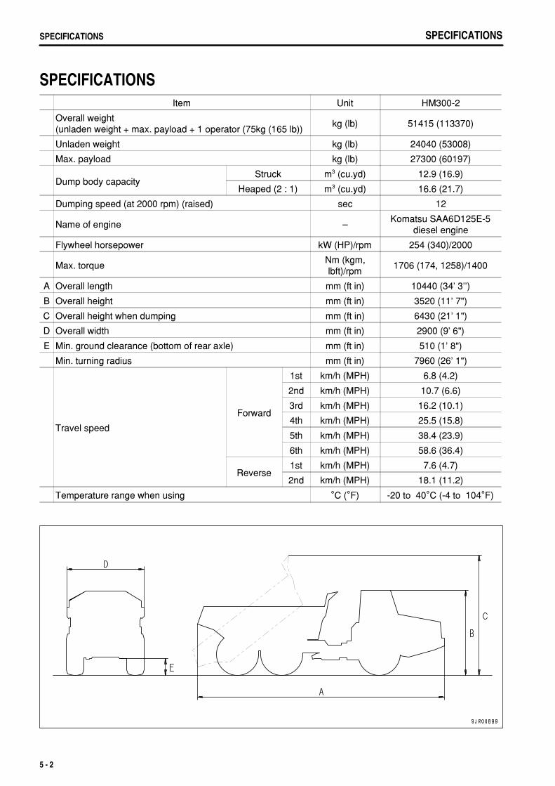
.
SPECIFICATIONSSPECIFICATIONS
SPECIFICATIONSItem Unit HM300-2
Overall weight(unladen weight + max. payload + 1 operator (75kg (165 lb))
kg (lb) 51415 (113370)
Unladen weight kg (lb) 24040 (53008)
Max. payload kg (lb) 27300 (60197)
Dump body capacityStruck m3 (cu.yd) 12.9 (16.9)
Heaped (2 : 1) m3 (cu.yd) 16.6 (21.7)
Dumping speed (at 2000 rpm) (raised) sec 12
Name of engine –Komatsu SAA6D125E-5
diesel engine
Flywheel horsepower kW (HP)/rpm 254 (340)/2000
Max. torqueNm (kgm,lbft)/rpm
1706 (174, 1258)/1400
A Overall length mm (ft in) 10440 (34' 3'')
B Overall height mm (ft in) 3520 (11' 7")
C Overall height when dumping mm (ft in) 6430 (21' 1")
D Overall width mm (ft in) 2900 (9' 6")
E Min. ground clearance (bottom of rear axle) mm (ft in) 510 (1' 8")
Min. turning radius mm (ft in) 7960 (26' 1")
Travel speed
Forward
1st km/h (MPH) 6.8 (4.2)
2nd km/h (MPH) 10.7 (6.6)
3rd km/h (MPH) 16.2 (10.1)
4th km/h (MPH) 25.5 (15.8)
5th km/h (MPH) 38.4 (23.9)
6th km/h (MPH) 58.6 (36.4)
Reverse1st km/h (MPH) 7.6 (4.7)
2nd km/h (MPH) 18.1 (11.2)
Temperature range when using °C (°F) -20 to 40°C (-4 to 104°F)
5 - 2

.
6 - 1
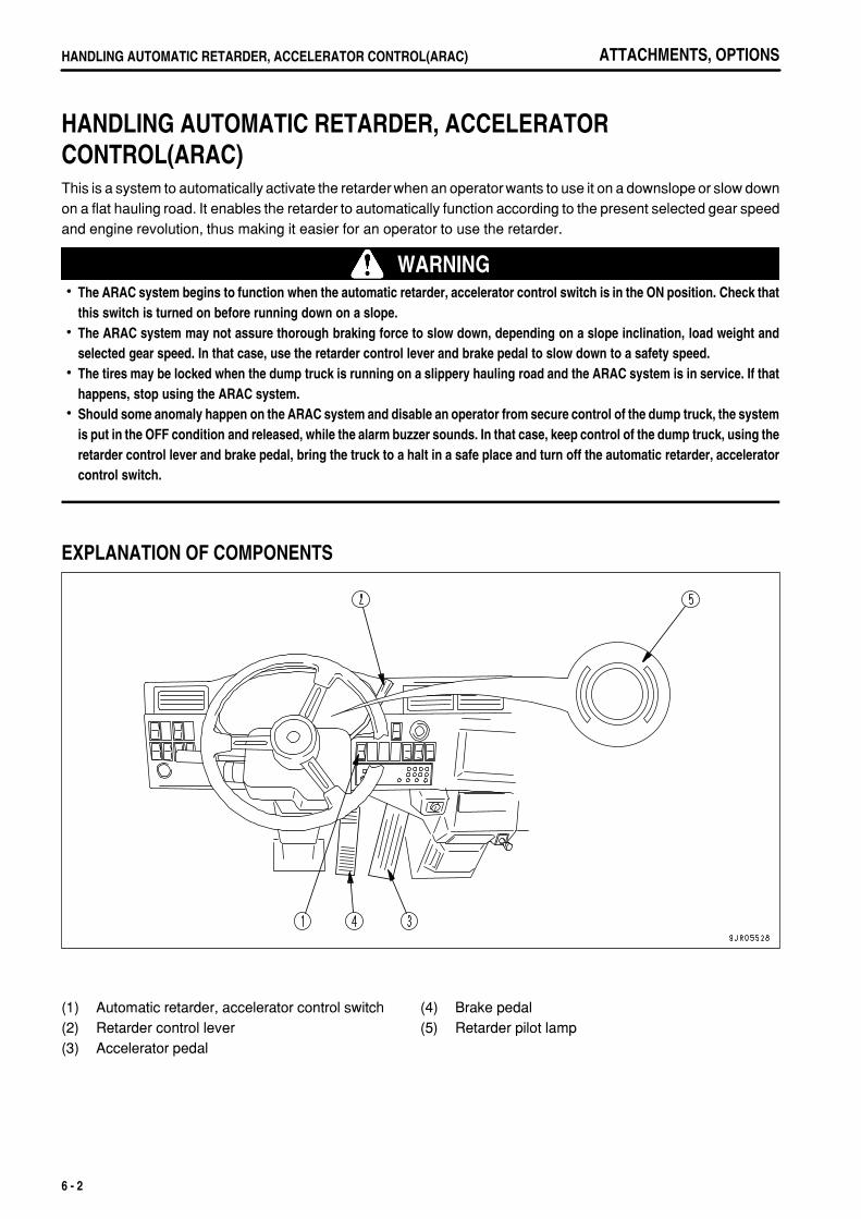
.
ATTACHMENTS, OPTIONSHANDLING AUTOMATIC RETARDER, ACCELERATOR CONTROL(ARAC)
HANDLING AUTOMATIC RETARDER, ACCELERATOR CONTROL(ARAC)This is a system to automatically activate the retarder when an operator wants to use it on a downslope or slow downon a flat hauling road. It enables the retarder to automatically function according to the present selected gear speedand engine revolution, thus making it easier for an operator to use the retarder.
WARNINGThe ARAC system begins to function when the automatic retarder, accelerator control switch is in the ON position. Check thatthis switch is turned on before running down on a slope. The ARAC system may not assure thorough braking force to slow down, depending on a slope inclination, load weight andselected gear speed. In that case, use the retarder control lever and brake pedal to slow down to a safety speed.The tires may be locked when the dump truck is running on a slippery hauling road and the ARAC system is in service. If thathappens, stop using the ARAC system.Should some anomaly happen on the ARAC system and disable an operator from secure control of the dump truck, the systemis put in the OFF condition and released, while the alarm buzzer sounds. In that case, keep control of the dump truck, using theretarder control lever and brake pedal, bring the truck to a halt in a safe place and turn off the automatic retarder, acceleratorcontrol switch.
EXPLANATION OF COMPONENTS
(1)(2)(3)
Automatic retarder, accelerator control switchRetarder control leverAccelerator pedal
(4)(5)
Brake pedalRetarder pilot lamp
6 - 2
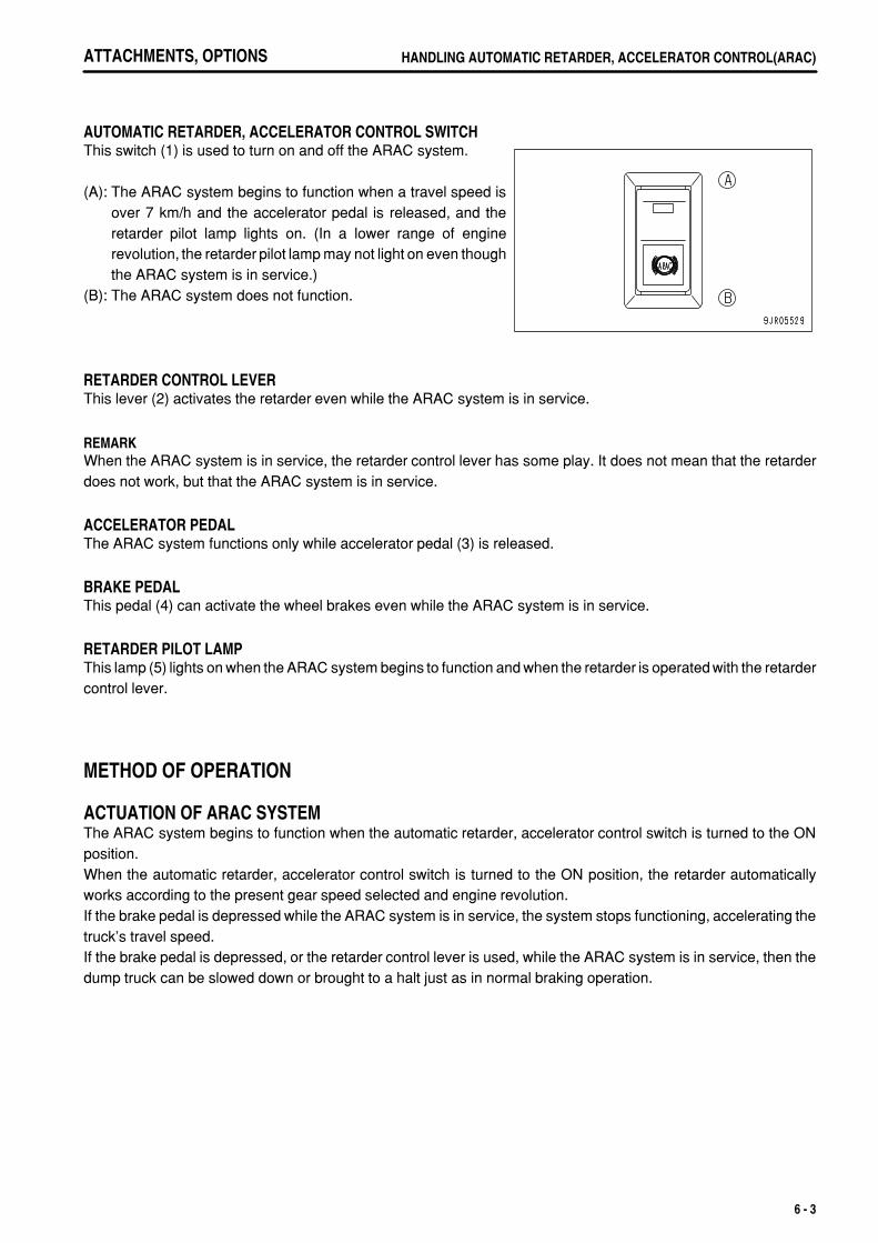
.
ATTACHMENTS, OPTIONS HANDLING AUTOMATIC RETARDER, ACCELERATOR CONTROL(ARAC)
AUTOMATIC RETARDER, ACCELERATOR CONTROL SWITCHThis switch (1) is used to turn on and off the ARAC system.
(A): The ARAC system begins to function when a travel speed isover 7 km/h and the accelerator pedal is released, and theretarder pilot lamp lights on. (In a lower range of enginerevolution, the retarder pilot lamp may not light on even thoughthe ARAC system is in service.)
(B): The ARAC system does not function.
RETARDER CONTROL LEVERThis lever (2) activates the retarder even while the ARAC system is in service.
REMARKWhen the ARAC system is in service, the retarder control lever has some play. It does not mean that the retarderdoes not work, but that the ARAC system is in service.
ACCELERATOR PEDALThe ARAC system functions only while accelerator pedal (3) is released.
BRAKE PEDALThis pedal (4) can activate the wheel brakes even while the ARAC system is in service.
RETARDER PILOT LAMPThis lamp (5) lights on when the ARAC system begins to function and when the retarder is operated with the retardercontrol lever.
METHOD OF OPERATION
ACTUATION OF ARAC SYSTEMThe ARAC system begins to function when the automatic retarder, accelerator control switch is turned to the ONposition.When the automatic retarder, accelerator control switch is turned to the ON position, the retarder automaticallyworks according to the present gear speed selected and engine revolution.If the brake pedal is depressed while the ARAC system is in service, the system stops functioning, accelerating thetruck's travel speed.If the brake pedal is depressed, or the retarder control lever is used, while the ARAC system is in service, then thedump truck can be slowed down or brought to a halt just as in normal braking operation.
6 - 3
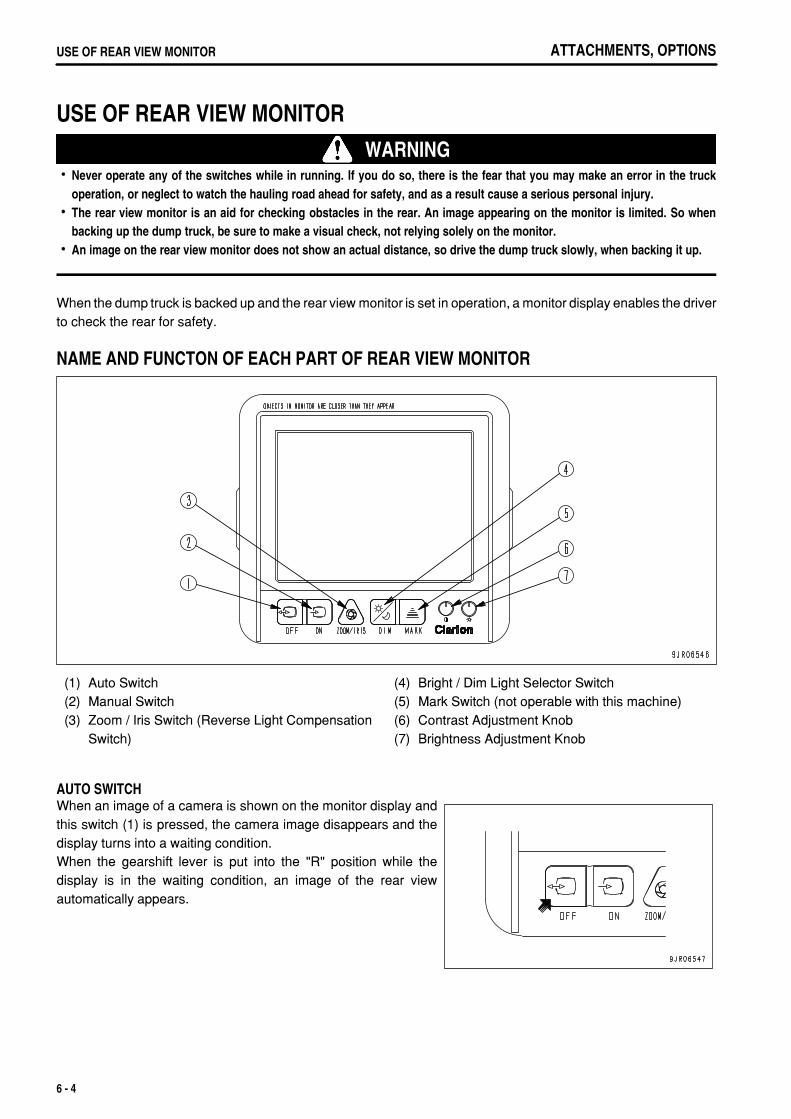
.
ATTACHMENTS, OPTIONSUSE OF REAR VIEW MONITOR
USE OF REAR VIEW MONITOR WARNING
Never operate any of the switches while in running. If you do so, there is the fear that you may make an error in the truckoperation, or neglect to watch the hauling road ahead for safety, and as a result cause a serious personal injury.The rear view monitor is an aid for checking obstacles in the rear. An image appearing on the monitor is limited. So whenbacking up the dump truck, be sure to make a visual check, not relying solely on the monitor.An image on the rear view monitor does not show an actual distance, so drive the dump truck slowly, when backing it up.
When the dump truck is backed up and the rear view monitor is set in operation, a monitor display enables the driverto check the rear for safety.
NAME AND FUNCTON OF EACH PART OF REAR VIEW MONITOR
(1)(2)(3)
Auto SwitchManual SwitchZoom / Iris Switch (Reverse Light CompensationSwitch)
(4)(5)(6)(7)
Bright / Dim Light Selector SwitchMark Switch (not operable with this machine)Contrast Adjustment KnobBrightness Adjustment Knob
AUTO SWITCHWhen an image of a camera is shown on the monitor display andthis switch (1) is pressed, the camera image disappears and thedisplay turns into a waiting condition.When the gearshift lever is put into the "R" position while thedisplay is in the waiting condition, an image of the rear viewautomatically appears.
6 - 4
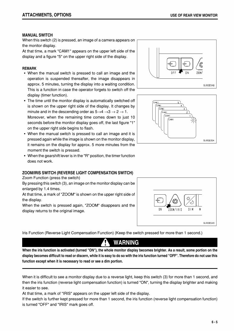
.
ATTACHMENTS, OPTIONS USE OF REAR VIEW MONITOR
MANUAL SWITCHWhen this switch (2) is pressed, an image of a camera appears onthe monitor display.At that time, a mark "CAM1" appears on the upper left side of thedisplay and a figure "5" on the upper right side of the display.
REMARKWhen the manual switch is pressed to call an image and theoperation is suspended thereafter, the image disappears inapprox. 5 minutes, turning the display into a waiting condition.This is a function in case the operator forgets to switch off thedisplay (timer function).The time until the monitor display is automatically switched offis shown on the upper right side of the display. It changes byminute and in the descending order as 5→4 →3 → 2 → 1.Moreover, when the remaining time comes down to just 10seconds before the monitor display goes off, the last figure "1"on the upper right side begins to flash.When the manual switch is pressed to call an image and it ispressed again while the image is shown on the monitor display,it remains on the display for approx. 5 more minutes from themoment the switch is pressed.When the gearshift lever is in the "R" position, the timer functiondoes not work.
ZOOM/IRIS SWITCH (REVERSE LIGHT COMPENSATION SWITCH)Zoom Function (press the switch)By pressing this switch (3), an image on the monitor display can beenlarged by 1.4 times.At that time, a mark of "ZOOM" is shown on the upper right side ofthe display.When the switch is pressed again, "ZOOM" disappears and thedisplay returns to the original image.
Iris Function (Reverse Light Compensation Function) (Keep the switch pressed for more than 1 second.)
WARNINGWhen the iris function is activated (turned "ON"), the whole monitor display becomes brighter. As a result, some portion on thedisplay becomes difficult to read or discern, while it is easy to do so with the iris function turned "OFF". Therefore do not use thisfunction except when it is necessary to read or see a dim portion.
When it is difficult to see a monitor display due to a reverse light, keep this switch (3) for more than 1 second, andthen the iris function (reverse light compensation function) is turned "ON", turning the display brighter and makingit easier to see.At that time, a mark of "IRIS" appears on the upper left side of the display.If the switch is further kept pressed for more than 1 second, the iris function (reverse light compensation function)is turned "OFF" and "IRIS" mark goes off.
6 - 5
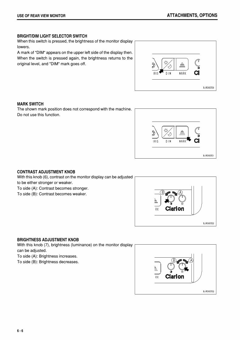
.
ATTACHMENTS, OPTIONSUSE OF REAR VIEW MONITOR
BRIGHT/DIM LIGHT SELECTOR SWITCHWhen this switch is pressed, the brightness of the monitor displaylowers.A mark of "DIM" appears on the upper left side of the display then.When the switch is pressed again, the brightness returns to theoriginal level, and "DIM" mark goes off.
MARK SWITCHThe shown mark position does not correspond with the machine.Do not use this function.
CONTRAST ADJUSTMENT KNOBWith this knob (6), contrast on the monitor display can be adjustedto be either stronger or weaker.To side (A): Contrast becomes stronger.To side (B): Contrast becomes weaker.
BRIGHTNESS ADJUSTMENT KNOBWith this knob (7), brightness (luminance) on the monitor displaycan be adjusted.To side (A): Brightness increases.To side (B): Brightness decreases.
6 - 6
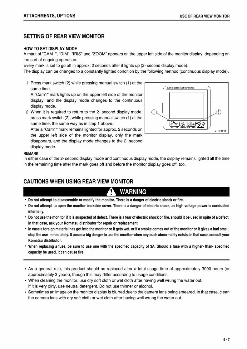
.
ATTACHMENTS, OPTIONS USE OF REAR VIEW MONITOR
SETTING OF REAR VIEW MONITOR
HOW TO SET DISPLAY MODEA mark of "CAM1", "DIM", "IRIS" and "ZOOM" appears on the upper left side of the monitor display, depending onthe sort of ongoing operation.Every mark is set to go off in approx. 2 seconds after it lights up (2- second display mode).The display can be changed to a constantly lighted condition by the following method (continuous display mode).
1. Press mark switch (2) while pressing manual switch (1) at thesame time.A "Cam1" mark lights up on the upper left side of the monitordisplay, and the display mode changes to the continuousdisplay mode.
2. When it is required to return to the 2- second display mode,press mark switch (2), while pressing manual switch (1) at thesame time, the same way as in step 1 above.After a "Cam1" mark remains lighted for approx. 2 seconds onthe upper left side of the monitor display, only the markdisappears, and the display mode changes to the 2- seconddisplay mode.
REMARKIn either case of the 2- second display mode and continuous display mode, the display remains lighted all the timein the remaining time after the mark goes off and before the monitor display goes off, too.
CAUTIONS WHEN USING REAR VIEW MONITOR
WARNINGDo not attempt to disassemble or modify the monitor. There is a danger of electric shock or fire.Do not attempt to open the monitor backside cover. There is a danger of electric shock, as high voltage power is conductedinternally.Do not use the monitor if it is suspected of defect. There is a fear of electric shock or fire, should it be used in spite of a defect.In that case, ask your Komatsu distributor for repair or replacement.In case a foreign material has got into the monitor or it gets wet, or if a smoke comes out of the monitor or it gives a bad smell,stop the use immediately. It poses a big danger to use the monitor when any such abnormality exists. In that case, consult yourKomatsu distributor.When replacing a fuse, be sure to use one with the specified capacity of 3A. Should a fuse with a higher- than- specifiedcapacity be used, it can cause fire.
As a general rule, this product should be replaced after a total usage time of approximately 3000 hours (orapproximately 3 years), though this may differ according to usage conditions.When cleaning the monitor, use dry soft cloth or wet cloth after having well wrung the water out.If it is very dirty, use neutral detergent. Do not use thinner or alcohol.Sometimes an image on the monitor display is blurred due to the camera lens being smeared. In that case, cleanthe camera lens with dry soft cloth or wet cloth after having well wrung the water out.
6 - 7
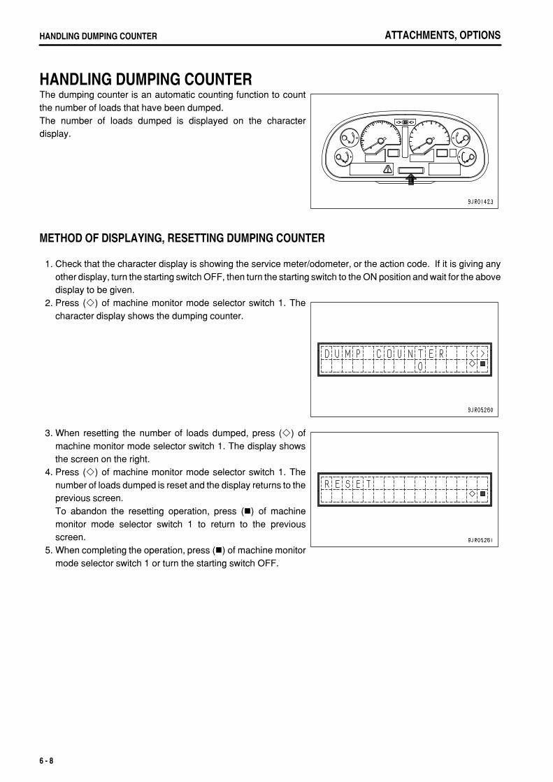
.
ATTACHMENTS, OPTIONSHANDLING DUMPING COUNTER
HANDLING DUMPING COUNTERThe dumping counter is an automatic counting function to countthe number of loads that have been dumped.The number of loads dumped is displayed on the characterdisplay.
METHOD OF DISPLAYING, RESETTING DUMPING COUNTER
1. Check that the character display is showing the service meter/odometer, or the action code. If it is giving anyother display, turn the starting switch OFF, then turn the starting switch to the ON position and wait for the abovedisplay to be given.
2. Press ( ) of machine monitor mode selector switch 1. Thecharacter display shows the dumping counter.
3. When resetting the number of loads dumped, press ( ) ofmachine monitor mode selector switch 1. The display showsthe screen on the right.
4. Press ( ) of machine monitor mode selector switch 1. Thenumber of loads dumped is reset and the display returns to theprevious screen.To abandon the resetting operation, press ( ) of machinemonitor mode selector switch 1 to return to the previousscreen.
5. When completing the operation, press ( ) of machine monitormode selector switch 1 or turn the starting switch OFF.
6 - 8
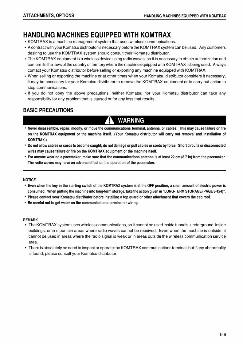
.
ATTACHMENTS, OPTIONS HANDLING MACHINES EQUIPPED WITH KOMTRAX
HANDLING MACHINES EQUIPPED WITH KOMTRAXKOMTRAX is a machine management system that uses wireless communications.A contract with your Komatsu distributor is necessary before the KOMTRAX system can be used. Any customersdesiring to use the KOMTRAX system should consult their Komatsu distributor.The KOMTRAX equipment is a wireless device using radio waves, so it is necessary to obtain authorization andconform to the laws of the country or territory where the machine equipped with KOMTRAX is being used. Alwayscontact your Komatsu distributor before selling or exporting any machine equipped with KOMTRAX.When selling or exporting the machine or at other times when your Komatsu distributor considers it necessary,it may be necessary for your Komatsu distributor to remove the KOMTRAX equipment or to carry out action tostop communications.If you do not obey the above precautions, neither Komatsu nor your Komatsu distributor can take anyresponsibility for any problem that is caused or for any loss that results.
BASIC PRECAUTIONS
WARNINGNever disassemble, repair, modify, or move the communications terminal, antenna, or cables. This may cause failure or fireon the KOMTRAX equipment or the machine itself. (Your Komatsu distributor will carry out removal and installation ofKOMTRAX.)Do not allow cables or cords to become caught; do not damage or pull cables or cords by force. Short circuits or disconnectedwires may cause failure or fire on the KOMTRAX equipment or the machine itself.For anyone wearing a pacemaker, make sure that the communications antenna is at least 22 cm (8.7 in) from the pacemaker.The radio waves may have an adverse effect on the operation of the pacemaker.
NOTICEEven when the key in the starting switch of the KOMTRAX system is at the OFF position, a small amount of electric power isconsumed. When putting the machine into long-term storage, take the action given in "LONG-TERM STORAGE (PAGE 3-124)".Please contact your Komatsu distributor before installing a top guard or other attachment that covers the cab roof.Be careful not to get water on the communications terminal or wiring.
REMARKThe KOMTRAX system uses wireless communications, so it cannot be used inside tunnels, underground, insidebuildings, or in mountain areas where radio waves cannot be received. Even when the machine is outside, itcannot be used in areas where the radio signal is weak or in areas outside the wireless communication servicearea.There is absolutely no need to inspect or operate the KOMTRAX communications terminal, but if any abnormalityis found, please consult your Komatsu distributor.
6 - 9

.
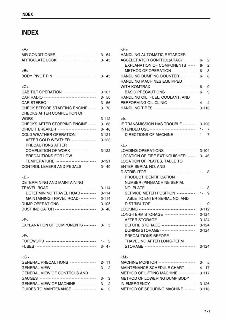
.
INDEX
INDEX
<A>AIR CONDITIONER 3- 64ARTICULATE LOCK 3- 45
<B>BODY PIVOT PIN 3- 45
<C>CAB TILT OPERATION 3-107CAR RADIO 3- 50CAR STEREO 3- 56CHECK BEFORE STARTING ENGINE 3- 70CHECKS AFTER COMPLETION OFWORK 3-112CHECKS AFTER STOPPING ENGINE 3- 88CIRCUIT BREAKER 3- 46COLD WEATHER OPERATION 3-121 AFTER COLD WEATHER 3-123 PRECAUTIONS AFTER COMPLETION OF WORK 3-122 PRECAUTIONS FOR LOW TEMPERATURE 3-121CONTROL LEVERS AND PEDALS 3- 40
<D>DETERMINING AND MAINTAININGTRAVEL ROAD 3-114 DETERMINING TRAVEL ROAD 3-114 MAINTAINING TRAVEL ROAD 3-114DUMP OPERATIONS 3-105DUST INDICATOR 3- 46
<E>EXPLANATION OF COMPONENTS 3- 5
<F>FOREWORD 1- 2FUSES 3- 47
<G>GENERAL PRECAUTIONS 2- 11GENERAL VIEW 3- 2GENERAL VIEW OF CONTROLS ANDGAUGES 3- 3GENERAL VIEW OF MACHINE 3- 2GUIDES TO MAINTENANCE 4- 2
<H>HANDLING AUTOMATIC RETARDER,ACCELERATOR CONTROL(ARAC) 6- 2 EXPLANATION OF COMPONENTS 6- 2 METHOD OF OPERATION 6- 3HANDLING DUMPING COUNTER 6- 8HANDLING MACHINES EQUIPPEDWITH KOMTRAX 6- 9 BASIC PRECAUTIONS 6- 9HANDLING OIL, FUEL, COOLANT, ANDPERFORMING OIL CLINIC 4- 4HANDLING TIRES 3-113
<I>IF TRANSMISSION HAS TROUBLE 3-126INTENDED USE 1- 7 DIRECTIONS OF MACHINE 1- 7
<L>LOADING OPERATIONS 3-104LOCATION OF FIRE EXTINGUISHER 3- 46LOCATION OF PLATES, TABLE TOENTER SERIAL NO. ANDDISTRIBUTOR 1- 8 PRODUCT IDENTIFICATION NUMBER (PIN)/MACHINE SERIAL NO. PLATE 1- 8 SERVICE METER POSITION 1- 9 TABLE TO ENTER SERIAL NO. AND DISTRIBUTOR 1- 9LOCKING 3-112LONG-TERM STORAGE 3-124 AFTER STORAGE 3-124 BEFORE STORAGE 3-124 DURING STORAGE 3-124 PRECAUTIONS BEFORE TRAVELING AFTER LONG-TERM STORAGE 3-124
<M>MACHINE MONITOR 3- 5MAINTENANCE SCHEDULE CHART 4- 17METHOD OF LIFTING MACHINE 3-117METHOD OF LOWERING DUMP BODYIN EMERGENCY 3-126METHOD OF SECURING MACHINE 3-116
7 - 1
.
INDEX
MOVING MACHINE OFF (FORWARD,REVERSE), STOPPING 3- 89
<O>OPERATION 3- 70OPERATION USING DIFFERENTIALLOCK 3-103OPERATIONS, CHECKS AFTERSTARTING ENGINE 3- 87OTHER FUNCTIONS OF MACHINEMONITOR 3- 26OUTLINE OF ELECTRIC SYSTEM 4- 8OUTLINE OF SERVICE 4- 4
<P>PARKING MACHINE 3-111PERIODIC REPLACEMENT OF SAFETYCRITICAL PARTS 4- 15PRECAUTIONS DURING OPERATION 2- 20 BATTERY 2- 27 OPERATION 2- 22 STARTING ENGINE 2- 20 TOWING 2- 29 TRANSPORTATION 2- 26PRECAUTIONS FOR MAINTENANCE 2- 30PRECAUTIONS FOR OPERATION 3-110PRECAUTIONS WHENTRANSPORTING 3-115PRECAUTIONS WITH TIRES 2- 37
<R>RECOMMENDED FUEL, COOLANT,AND LUBRICANT 4- 10 RECOMMENDED BRANDS, RECOMMENDED QUALITY FOR PRODUCTS OTHER THAN KOMATSU GENUINE OIL 4- 12 USE OF FUEL, COOLANT AND LUBRICANTS ACCORDING TO AMBIENT TEMPERATURE 4- 11
<S>SAFETY 2- 2SAFETY CRITICAL PARTS 4- 16SAFETY INFORMATION 1- 5
SAFETY LABELS 2- 4SERVICE PROCEDURE 4- 19 CHECK BEFORE STARTING 4- 39 EVERY 1000 HOURS SERVICE 4- 60 EVERY 2000 HOURS SERVICE 4- 71 EVERY 250 HOURS SERVICE 4- 41 EVERY 4000 HOURS SERVICE 4- 77 EVERY 50 HOURS SERVICE 4- 40 EVERY 500 HOURS SERVICE 4- 53 EVERY 6000 HOURS SERVICE 4- 79 EVERY 8000 HOURS SERVICE 4- 80 INITIAL 250 HOURS SERVICE (ONLY AFTER THE FIRST 250 HOURS) 4- 19 WHEN REQUIRED 4- 20SHIFTING GEAR 3- 94SPECIFICATIONS 5- 2STANDARD TIGHTENING TORQUESFOR BOLTS AND NUTS 4- 13STARTING ENGINE 3- 85STEERING THE MACHINE 3-102STEPS FOR TRANSPORTATION 3-115STOPPING ENGINE 3- 88SWITCHES 3- 30
<T>TORQUE LIST 4- 13TRANSPORTATION 3-115TRAVELING DOWNHILL 3- 96TROUBLESHOOTING 3-125 AFTER RUNNING OUT OF FUEL 3-125 IF BATTERY IS DISCHARGED 3-131 METHOD OF TOWING MACHINE 3-127 OTHER TROUBLE 3-135
<U>USE OF REAR VIEW MONITOR 6- 4 CAUTIONS WHEN USING REAR VIEW MONITOR 6- 7 NAME AND FUNCTON OF EACH PART OF REAR VIEW MONITOR 6- 4 SETTING OF REAR VIEW MONITOR 6- 7
<W>WEAR PARTS 4- 9WEAR PARTS LIST 4- 9
7 - 2

.
.
HM300-2 GALEO ARTICULATED DUMP TRUCKForm No. PEN00101-04
©2007 KOMATSUAll Rights ReservedPrinted in Japan 06-07