dual fluidized-bed steam gasification of solid feedstock ...saiche.co.za/files/filedoc/v17 n1 2012...
TRANSCRIPT
Dual fluidized-bed steam gasification of solid feedstock: Matching syngas requirements
with fuel mixtures
S. Kern, C. Pfeifer and H. Hofbauer Vienna University of Technology, Institute of Chemical Engineering
Vienna, Austria
Keywords: gasification, biomass, coal, dual fluidized bed, syngas
Abstract—Gasification of solid fuels has attracted increasing interest within the power industry for synthesis processes for liquid and gaseous fuel production. In addition to a high purity of syngas, the tar content and minor impurities (NH3, H2S, HCl), the gas composition has a major influence on the performance of any downstream utilization. The dual fluidized bed gasification technology developed at the Vienna University of Technology has been investigated for biomass use on a pilot scale over the last 15 years. Moreover, this process has also been demonstrated on an industrial scale. Allothermal (indirect) gasification with a solid heat carrier to transport the desired heat for gasification to the gasifier and the utilization of steam as a gasification agent ensures a high quality syngas that is nearly free of nitrogen. Originally designed for wood chips, the system can also handle a large number of alternative fuels. The advantage of fuel flexibility has turned out to be a key issue for the commercial breakthrough of this technology. To point out the influence on the system performance of fuels that have a different origin, wood pellets, as the designated feedstock and hard coal as an example fossil fuel were fed into the DFB gasifier in different blends to generate operating figures for coal ratios from 0% to 100%.
INTRODUCTION The world’s energy demand is growing constantly and the greater part of this growth is covered by oil and gas.1 Up to the last few years, coal-based gasification processes for power generation did not prove themselves to have an economic advantage compared to combustion power plants using coal or other fossil fuels. However, there is a current focus on renewable energy, and biomass gasification has been studied in detail in recent years. Since carbon dioxide emissions from biomass are perceived as being neutral2, and since coal is a fuel with a high availability and is less expensive than oil, the gasification of mixtures of these two oil alternatives is a natural consequence. The combination of biomass and coal offers the opportunity to build larger plants with higher feedstock flexibility and, moreover, allows for adjusting the producer gas composition according to the utilization route. Generally, co-firing is the use of different fuels at the same time for combustion. For example, biomass is co-fired in existing coal plants with fuels that cannot be burned alone because of the low energy content (such as sewage sludge), but can be burned together with natural gas with good performance. In industrial coal-fired power plants, co-firing can be used to reduce CO2 emissions without any loss in efficiency and with only minor changes to the plant’s settings. Therefore, only low percentages of biomass are usually used. Co-combustion of biomass with coal is a matter of intensive research for different applications, and several comprehensive studies exist on this topic.3–7 Co-firing can be accomplished via three different modifications, which are direct, indirect and parallel co-firing. For direct co-firing, a mixture of the standard fuel and the additional fuel is burned together in the boiler, while for parallel co-firing, a separate boiler where only the additional fuel is burned would be required. For indirect co-firing, a separated
13
gasification unit is required. However, in the case of co-gasification of biomass and fossil fuels at different ratios, the literature is sparse.8–15 Dual fluidized bed gasification technology16,17, developed at the Vienna University of Technology, has also been successfully demonstrated in Güssing and Oberwart, Austria, on the 8 and 10 MW scale, respectively, for several years.18,19 Also, the operation of these demonstration plants for heat and power generation have pointed out that fuel flexibility is a key issue for commercial and economic breakthrough. Therefore coal, as a fuel that is available in large amounts and is therefore on hand at low prices, was chosen. Also, from a scientific point of view, the utilization of coal in the system originally designed for biomass is very promising as the fuels have totally different compositions with respect to volatile components and carbon contents. During a previous experimental campaign, the combined heat and power (CHP) gasification plant in Güssing was operated with coal ratios up to 22% in terms of energy. These tests were quite successful as they showed that the dual fluidized bed design can also handle coal as a fuel.20 The utilization of the syngas, produced by the process, is not limited to heat and power production in a gas engine or a boiler; there is also a huge potential for the production of liquid or gaseous fuels from syngas21 by Fischer-Tropsch synthesis, mixed alcohols synthesis or the production of synthetic natural gas. These processes can use syngas made by the gasification of solid feedstock as a source, but every process requires a certain syngas composition, in terms of its H2/CO ratio, to sustain optimal operation. For example, the basic Fischer-Tropsch synthesis reaction needs a H2 to CO ratio of 2:1 if there is no water-gas shift reaction promoted by a certain catalyst.22,23 The production of synthetic natural gas requires an even higher H2/CO ratio of at least 3:1.24 Regarding these requirements, the composition of syngas, especially the H2 to CO ratio, should be as close as possible to the required ratio to maximize product yields and process performance. The possibilities of changing syngas compositions are limited. On the one hand, the process parameters, such as gasification temperature, steam to fuel ratio or different bed materials, can be varied only within a limited range, and the net effect on the gas composition is only marginal.17 The other possibility is to use a different fuel such as coal that has, in contrast to biomass, a low atomic H/C and O/C ratio which leads to higher hydrogen and lower carbon monoxide yields.
EXPERIMENTAL PROCEDURE
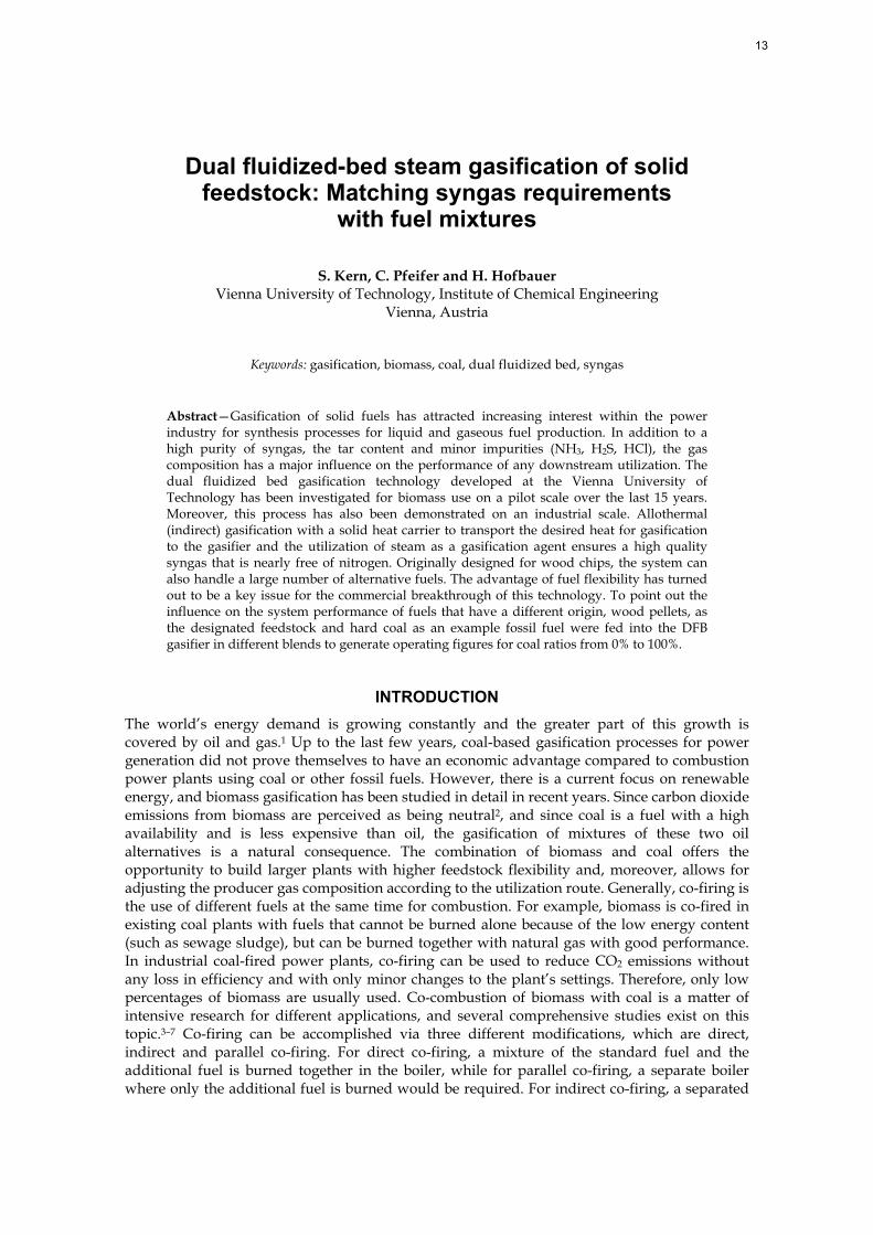
Experimental setup For the experiments on the pilot scale, at the Vienna University of Technology, a 100 kW dual fluidized bed gasification reactor is in operation. The basic principle of the dual fluidized bed gasification process is shown in Figure 1 and a schematic drawing of the pilot rig is shown in Figure 2.
Figure 1. Principles behind the dual fluidized bed
gasifier
This system separates the gasification zone and the combustion zone as two fluidized bed reactors, connected together by loop seals. The fuel, usually biomass, enters the gasification reactor, a bubbling fluidized bed fluidized with steam, where drying, pyrolysis and
14

heterogeneous char gasification take place at bed temperatures of up to 900°C. The remaining residual char leaves the gasification reactor at the bottom together with the bed material, which circulates between the two reactors, through the lower loop seal to the combustion reactor. This reactor is implemented as a fast fluidized bed that is fluidized with air to maintain combustion of the residual char and additional fuel, if required.
Figure 2. Schematic drawing of the gasifier
By burning char and additional fuel in the combustion reactor, the bed material is heated up, and after particle separation at the exit of flue gas from the combustion reactor, it flows back to the gasifier via the upper loop seal. Both the lower and upper loop seals are fluidized with steam to ensure a high throughput of bed material and to avoid any leakage of gas between the reactors. The temperature difference between the combustion and the gasification reactors is determined by the energy needed for gasification as well as the circulation rate of the bed material. The system is inherently auto-stabilizing since a decrease in the gasification temperature leads to higher amounts of residual char, which results in more fuel for the combustion reactor. This, in turn, transports more energy into the gasification zone and thereby stabilizes the temperature.
Table 1. Basic geometry data of the dual fluidized bed system
Unit Gasification reactor Combustion reactor Geometry Conical bottom section with
square-shaped upper freeboard section
Cylindrical
Reactor inner diameter mm 304 (equivalent cylindrical diameter)
98
Reactor free height m 2.35 3.9
In practical operations, the gasification temperature is controlled by the addition of fuel (e.g. recycled producer gas, sawdust, etc.) into the combustion reactor. In the case of the 100 kW pilot rig, light heating oil is used as an additional fuel as it is easy to handle for processes on the
15
pilot scale. The pressure in both gasification and combustion reactors is close to atmospheric conditions. The basic geometry data of the loop seal interconnected dual fluidized bed reactor system is summarized in Table 1. The main operable conditions of the DFB pilot plant are presented in Table 2.
Table 2. Main operable conditions
Unit Gasifier Combustion reactor (riser) Operable temperature range °C 650-870 750-920
Fluidization agent steam air Fluidization regime Bubbling fluidized bed Fast fluidized bed
Steam/fuel ratio 0.5-2.0
The process yields two separate gas streams at high temperatures: a high quality producer gas and a conventional flue gas. The producer gas for biomass gasification is generally characterized by a relatively low content of condensable higher hydrocarbons (2–10 g/m³ of so called tars, heavier than toluene), low N2 (< 1 vol.-%db), and a high H2 content of 35–40 vol.-%db. For practical use, olivine, a natural mineral, has been shown to be a suitable bed material with enough resistance to attrition and moderate tar cracking activity.
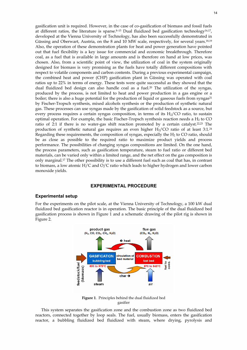
Analysis The permanent gas components CH4, H2, CO, CO2, and O2 were measured by a Rosemount NGA 2000. The components N2, C2H4, C2H6, and C3H8 were measured via an online gas chromatograph (Syntech Spectras GC955). Tar was sampled isokinetically using washing bottles with toluene as an absorption liquid, and gravimetric as well as GC/MS tar were determined with this procedure. A scheme of the arrangement of the tar sampling line is shown in Figure 3.
Figure 3. Tar sampling line
For the measurement of ammonia, gas was sampled in a method similar to the tar measurements, using washing bottles. The solvent used in this procedure was diluted sulfuric acid at a temperature of 2°C. Hydrogen sulfide was again sampled first using washing bottles filled with an aqueous potassium hydroxide solution at a temperature of 2°C. Subsequently, H2S values were determined by potentiometry. The flue gas was measured with a Rosemount NGA 2000 (CO, CO2, and O2). Sulfuric dioxide (SO2) was measured by potentiometry after sampling with washing bottles with an aqueous potassium hydroxide solution as the absorption liquid at a temperature of 2°C. Details of the measurement methods can be found in reference 25.
Balance of the pilot plant To calculate balances of the system, measuring points for several temperatures, pressures and volumetric flows are available at the plant. The composition of syngas, flue gas and feedstock are also determined, but there are some parameters that cannot be measured. Such a value is, for example the flow, of the syngas. Due to different gas compositions, different loads of dust, char and tar in the syngas, the construction of a measuring orifice is not meaningful. In such a
16
case, the values have to be calculated by a balance of the plant. The complexity of such plants is high, which requires thermodynamic calculations of high accuracy. That is why the calculation of mass and energy balances has to be done using computer-aided methods. For this purpose, the balance tool IPSEpro was used. IPSEpro is a stationary, equation-oriented flow sheet simulation tool that has been developed for power systems.26 It has been used at the Institute of Chemical Engineering for biomass-based energy systems for many years and therefore the models of the process are constantly being improved and advanced. Detailed information on IPSEpro, its mode of operation and its utilization for biomass-based energy systems can be found in references 27 and 28.
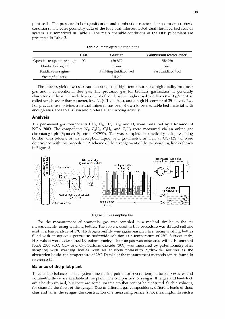
RESULTS AND DISCUSSION To gain knowledge on the influence on the gasification products and the performance of the process, five tests with coal ratios from 0% to 100% were performed in the 100 kW dual fluidized bed gasification pilot rig. For this test campaign, a fuel power (wood pellets and coal) of about 80 kW and a gasification temperature of 870°C as the mean temperature in the fluidized bed was chosen. The fluidizing conditions were kept constant for all five tests, so there was always the same amount of steam and air for fluidization. Operational parameters that are the result of the fluidizing conditions and fuel composition, such as the steam to fuel ratio, which changed during the tests, will be dealt with comprehensively in the experimental section. The regime map of the fluidizing conditions is given in Figure 4 (merged from references 29–31). In this diagram, it is shown that the regime in the gasification section of the reactor is a bubbling bed, whereas the combustion section lies in the fast fluidization section.
Figure 4. Mapping of fluidization regime32 showing location of gasification section (yellow) and
combustion section (red)
The operational area is determined by the fact that producer gas is produced in the bed over the height, and in the combustion section, air is introduced at two different levels. The superficial gas velocity in the riser after the secondary air inlet ranges from 10 to 10.5 m/s, whereas superficial gas velocities of 0.38 to 0.55 m/s occur in the gasification zone. Detailed fluidization facts are shown afterwards. Wood pellets produced according to the Austrian standard ÖNORM M 7135 are usually used as a standard fuel to represent wood in the gasifier. For the processing of biomass in a power plant, wood chips are mostly the designated fuel, but for the 100 kW pilot plant, the pieces have to be smaller, and the quality of the fuel has to be held constant for the entire test campaign. Therefore, instead of wood chips, wood pellets were
17
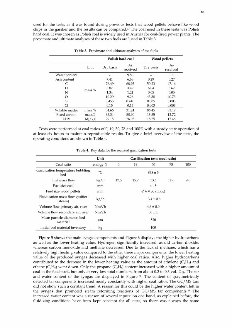
used for the tests, as it was found during previous tests that wood pellets behave like wood chips in the gasifier and the results can be compared.17 The coal used in these tests was Polish hard coal. It was chosen as Polish coal is widely used in Austria for coal-fired power plants. The proximate and ultimate analyses of these two fuels are listed in Table 3.
Table 3. Proximate and ultimate analyses of the fuels
Polish hard coal Wood pellets
Unit Dry basis As received Dry basis As
received Water content – 9.86 – 6.11 Ash content 7.41 6.68 0.29 0.27
C 76.49 68.95 50.23 47.16 H 3.87 3.49 6.04 5.67 N 1.34 1.21 0.05 0.05 O 10.29 9,26 43.38 40.73 S Cl
mass %
0.455 0.15
0.410 0.14
0.005 0.003
0.005 0.003
Volatile matter mass % 34.66 31.24 86.45 81.17 Fixed carbon mass% 65.34 58.90 13.55 12.72
LHV MJ/kg 29.15 26.03 18.75 17.46 Tests were performed at coal ratios of 0, 19, 50, 78 and 100% with a steady state operation of
at least six hours to maintain reproducible results. To give a brief overview of the tests, the operating conditions are shown in Table 4.
Table 4. Key data for the realized gasification tests
Unit Gasification tests (coal ratio) Coal ratio energy-% 0 19 50 78 100
Gasification temperature bubbling bed °C 868 ± 5
Fuel mass flow kg/h 17.5 15.7 13.6 11.6 9.6 Fuel size coal mm 4 - 8
Fuel size wood pellets mm Ø 6 × 30 (max.) Fluidization mass flow gasifier
(steam) kg/h 13.4 ± 0.6
Volume flow primary air, riser Nm³/h 4.6 ± 0.0 Volume flow secondary air, riser Nm³/h 50 ± 1
Mean particle diameter, bed material µm 520
Initial bed material inventory kg 100
Figure 5 shows the main syngas components and Figure 6 displays the higher hydrocarbons as well as the lower heating value. Hydrogen significantly increased, as did carbon dioxide, whereas carbon monoxide and methane decreased. Due to the lack of methane, which has a relatively high heating value compared to the other three major components, the lower heating value of the produced syngas decreased with higher coal ratios. Also, higher hydrocarbons contributed to the decrease in the lower heating value as the amount of ethylene (C2H4) and ethane (C2H6) went down. Only the propane (C3H8) content increased with a higher amount of coal in the feedstock, but only at very low total numbers, from about 0.2 to 0.3 vol.-%db. The tar and water content of the syngas are displayed in Figure 7. The content of gravimetrically detected tar components increased nearly constantly with higher coal ratios. The GC/MS tars did not show such a constant trend. A reason for this could be the higher water content left in the syngas that promoted steam reforming reactions of GC/MS tar components.33 The increased water content was a reason of several inputs: on one hand, as explained before, the fluidizing conditions have been kept constant for all tests, so there was always the same
18
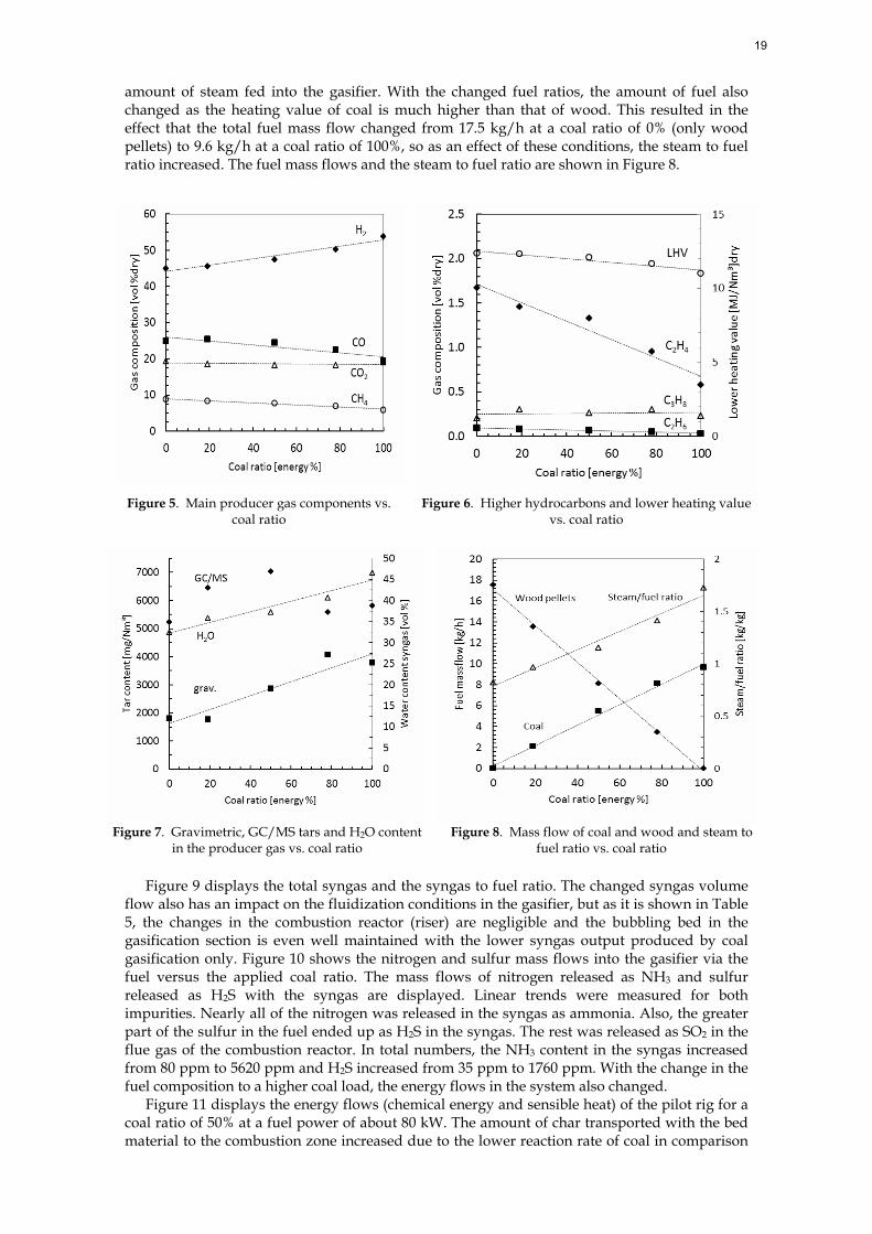
amount of steam fed into the gasifier. With the changed fuel ratios, the amount of fuel also changed as the heating value of coal is much higher than that of wood. This resulted in the effect that the total fuel mass flow changed from 17.5 kg/h at a coal ratio of 0% (only wood pellets) to 9.6 kg/h at a coal ratio of 100%, so as an effect of these conditions, the steam to fuel ratio increased. The fuel mass flows and the steam to fuel ratio are shown in Figure 8.
Figure 5. Main producer gas components vs. coal ratio
Figure 6. Higher hydrocarbons and lower heating value vs. coal ratio
Figure 7. Gravimetric, GC/MS tars and H2O content
in the producer gas vs. coal ratio Figure 8. Mass flow of coal and wood and steam to
fuel ratio vs. coal ratio
Figure 9 displays the total syngas and the syngas to fuel ratio. The changed syngas volume flow also has an impact on the fluidization conditions in the gasifier, but as it is shown in Table 5, the changes in the combustion reactor (riser) are negligible and the bubbling bed in the gasification section is even well maintained with the lower syngas output produced by coal gasification only. Figure 10 shows the nitrogen and sulfur mass flows into the gasifier via the fuel versus the applied coal ratio. The mass flows of nitrogen released as NH3 and sulfur released as H2S with the syngas are displayed. Linear trends were measured for both impurities. Nearly all of the nitrogen was released in the syngas as ammonia. Also, the greater part of the sulfur in the fuel ended up as H2S in the syngas. The rest was released as SO2 in the flue gas of the combustion reactor. In total numbers, the NH3 content in the syngas increased from 80 ppm to 5620 ppm and H2S increased from 35 ppm to 1760 ppm. With the change in the fuel composition to a higher coal load, the energy flows in the system also changed.
Figure 11 displays the energy flows (chemical energy and sensible heat) of the pilot rig for a coal ratio of 50% at a fuel power of about 80 kW. The amount of char transported with the bed material to the combustion zone increased due to the lower reaction rate of coal in comparison
19

to biomass. Hence, more thermal energy bound in char was available in the combustion part of the facility and less additional fuel had to be burned in the combustor. This behavior was primarily caused by the amount of volatile components of the fuel as it gives an indication about how much char is produced in the gasifier. This also resulted in a linear correlation between volatile components and required additional fuel as displayed in Figure 12. It can be seen that a high content of volatile components in the fuel requires more additional fuel for the combustion reactor of the gasifier to provide the required heat.
Table 5. Fluidization data for gasification and combustion reactor
Unit Gasification tests (coal ratio) Coal ratio energy-% 0 19 50 78 100
Minimum fluidization velocity, Umf,dp50
m/s 0.14 0.14 0.14 0.14 0.14
Minimum terminal velocity, Umt,dp50 m/s 5.40 5.40 5.40 5.40 5.40 Superficial gas velocity gasifier, UG m/s 0.55 0.51 0.47 0.43 0.38
UG/Umf 3.98 3.47 3.43 3.10 2.77 UG/Umt 0.10 0.10 0.09 0.08 0.07
Superficial gas velocity riser, UR m/s 10.14 10.38 10.47 10.47 10.50 UR/Umf 74.02 75.77 76.45 76.45 76.64 UR/Umt 1.88 1.92 1.94 1.94 1.94
Figure 9. Syngas volume flow and syngas yield per fuel
input vs. coal ratio Figure 10. Nitrogen and sulfur mass flows in/out vs.
coal ratio
During this test series, the consumption of additional fuel was relatively high, as the load was reduced from the design fuel power of 100 kW down to about 80 kW. This decision was made in order to ensure stationary conditions for all coal ratios up to 100%. One critical parameter is the gasification temperature, which will increase if more carbon accumulates in the system than is necessary to sustain the gasification reactions. This state can be determined if no additional fuel is necessary. The heat loss of the pilot plant is also much higher than for large-scale industrial plants, so even with reduced power, there is basically the same heat loss as at the nominal power level. The heat losses for gasification reactor and combustion reactor were nearly constant for these tests as gasification and combustion temperature were in the same range. For the chosen gasification temperature and fuel power, the heat loss of the gasification reactor was around 8 kW and the heat loss of the combustion reactor was 4 kW. However these numbers are not representative as a pilot plant is, in most of the cases, not able to reach the negligible heat loss of a commercial plant. So in relation to the input power, the heat losses are much higher, about 18% for these tests. In other words, if the fuel power of the pilot plant is increased using fuels with a low content of volatile components, the amount of additional fuel is reduced and the net efficiency increases as losses diminish. Figure 13 summarizes the effects of the load ratios of coal on the performance of the syngas where the
20
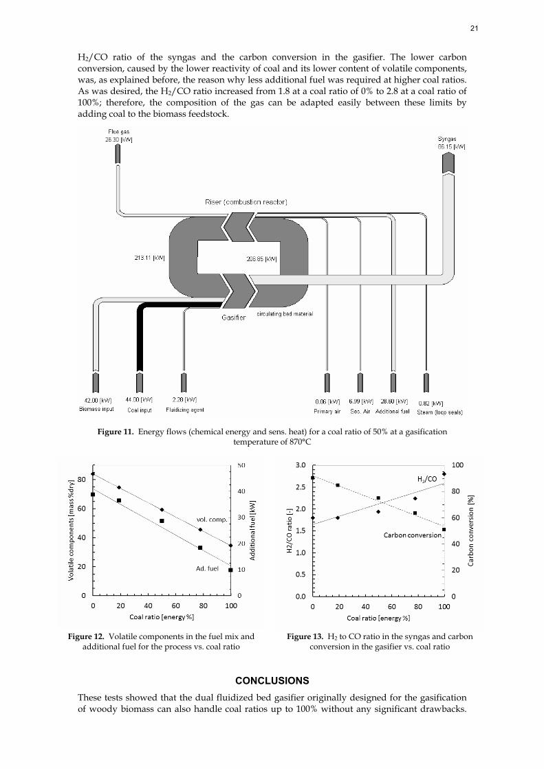
H2/CO ratio of the syngas and the carbon conversion in the gasifier. The lower carbon conversion, caused by the lower reactivity of coal and its lower content of volatile components, was, as explained before, the reason why less additional fuel was required at higher coal ratios. As was desired, the H2/CO ratio increased from 1.8 at a coal ratio of 0% to 2.8 at a coal ratio of 100%; therefore, the composition of the gas can be adapted easily between these limits by adding coal to the biomass feedstock.
Figure 11. Energy flows (chemical energy and sens. heat) for a coal ratio of 50% at a gasification temperature of 870°C
Figure 12. Volatile components in the fuel mix and
additional fuel for the process vs. coal ratio Figure 13. H2 to CO ratio in the syngas and carbon
conversion in the gasifier vs. coal ratio
CONCLUSIONS These tests showed that the dual fluidized bed gasifier originally designed for the gasification of woody biomass can also handle coal ratios up to 100% without any significant drawbacks.
21
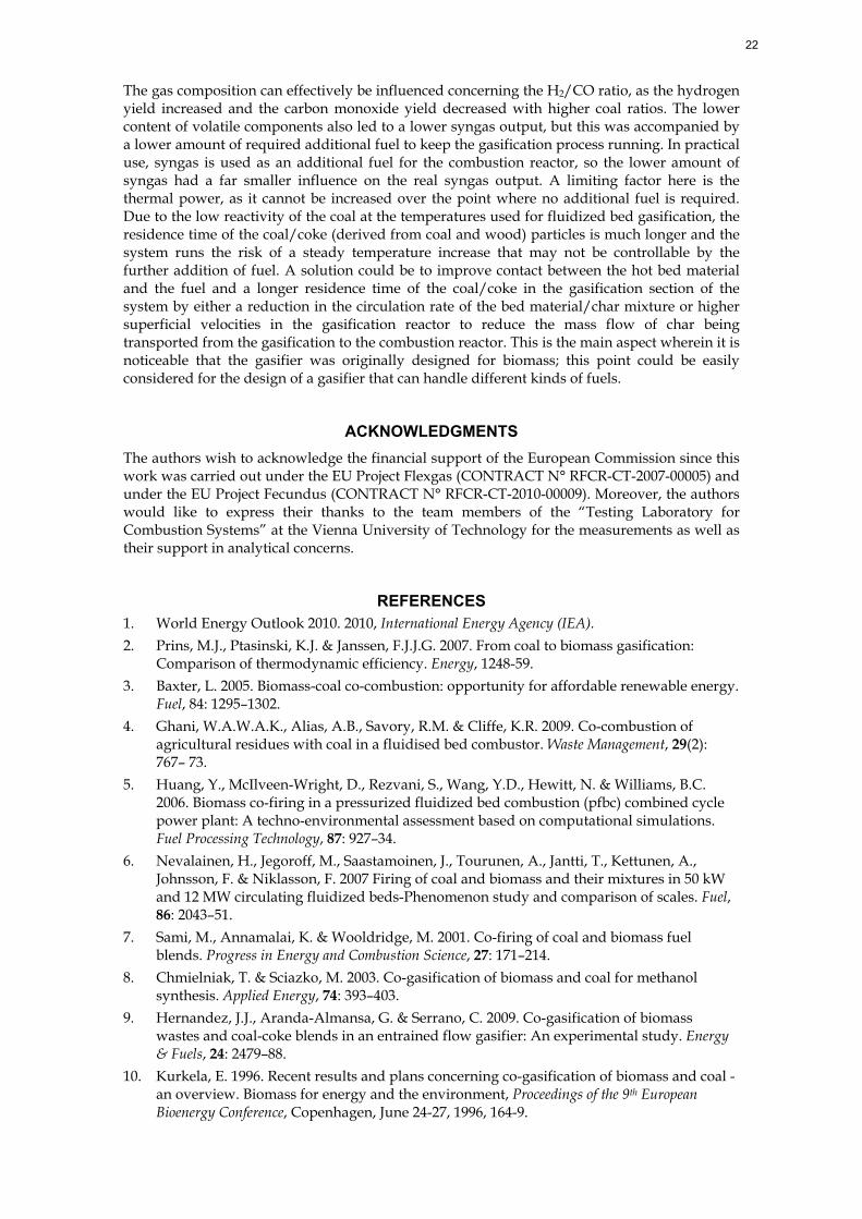
The gas composition can effectively be influenced concerning the H2/CO ratio, as the hydrogen yield increased and the carbon monoxide yield decreased with higher coal ratios. The lower content of volatile components also led to a lower syngas output, but this was accompanied by a lower amount of required additional fuel to keep the gasification process running. In practical use, syngas is used as an additional fuel for the combustion reactor, so the lower amount of syngas had a far smaller influence on the real syngas output. A limiting factor here is the thermal power, as it cannot be increased over the point where no additional fuel is required. Due to the low reactivity of the coal at the temperatures used for fluidized bed gasification, the residence time of the coal/coke (derived from coal and wood) particles is much longer and the system runs the risk of a steady temperature increase that may not be controllable by the further addition of fuel. A solution could be to improve contact between the hot bed material and the fuel and a longer residence time of the coal/coke in the gasification section of the system by either a reduction in the circulation rate of the bed material/char mixture or higher superficial velocities in the gasification reactor to reduce the mass flow of char being transported from the gasification to the combustion reactor. This is the main aspect wherein it is noticeable that the gasifier was originally designed for biomass; this point could be easily considered for the design of a gasifier that can handle different kinds of fuels.
ACKNOWLEDGMENTS The authors wish to acknowledge the financial support of the European Commission since this work was carried out under the EU Project Flexgas (CONTRACT N° RFCR-CT-2007-00005) and under the EU Project Fecundus (CONTRACT N° RFCR-CT-2010-00009). Moreover, the authors would like to express their thanks to the team members of the “Testing Laboratory for Combustion Systems” at the Vienna University of Technology for the measurements as well as their support in analytical concerns.
REFERENCES 1. World Energy Outlook 2010. 2010, International Energy Agency (IEA). 2. Prins, M.J., Ptasinski, K.J. & Janssen, F.J.J.G. 2007. From coal to biomass gasification:
Comparison of thermodynamic efficiency. Energy, 1248-59. 3. Baxter, L. 2005. Biomass-coal co-combustion: opportunity for affordable renewable energy.
Fuel, 84: 1295–1302. 4. Ghani, W.A.W.A.K., Alias, A.B., Savory, R.M. & Cliffe, K.R. 2009. Co-combustion of
agricultural residues with coal in a fluidised bed combustor. Waste Management, 29(2): 767– 73.
5. Huang, Y., McIlveen-Wright, D., Rezvani, S., Wang, Y.D., Hewitt, N. & Williams, B.C. 2006. Biomass co-firing in a pressurized fluidized bed combustion (pfbc) combined cycle power plant: A techno-environmental assessment based on computational simulations. Fuel Processing Technology, 87: 927–34.
6. Nevalainen, H., Jegoroff, M., Saastamoinen, J., Tourunen, A., Jantti, T., Kettunen, A., Johnsson, F. & Niklasson, F. 2007 Firing of coal and biomass and their mixtures in 50 kW and 12 MW circulating fluidized beds-Phenomenon study and comparison of scales. Fuel, 86: 2043–51.
7. Sami, M., Annamalai, K. & Wooldridge, M. 2001. Co-firing of coal and biomass fuel blends. Progress in Energy and Combustion Science, 27: 171–214.
8. Chmielniak, T. & Sciazko, M. 2003. Co-gasification of biomass and coal for methanol synthesis. Applied Energy, 74: 393–403.
9. Hernandez, J.J., Aranda-Almansa, G. & Serrano, C. 2009. Co-gasification of biomass wastes and coal-coke blends in an entrained flow gasifier: An experimental study. Energy & Fuels, 24: 2479–88.
10. Kurkela, E. 1996. Recent results and plans concerning co-gasification of biomass and coal - an overview. Biomass for energy and the environment, Proceedings of the 9th European Bioenergy Conference, Copenhagen, June 24-27, 1996, 164-9.
22

11. McLendon, T.R., Lui, A.P., Pineault, R.L., Beer, S.K. & Richardson, S. W. 2004. High-pressure co-gasification of coal and biomass in a fluidized bed. Biomass and Bioenergy, 26: 377–88.
12. Kumabe, K., Hanaoka, T., Fujimoto, S., Minowa, T. & Sakanishi, K. 2007. Co-gasification of woody biomass and coal with air and steam. Fuel, 86: 684–9.
13. Aigner, I., Pfeifer, C. & Hofbauer, H. 2010. Co-gasification of coal and wood in a dual fluidized bed gasifier: Variation of fluidization conditions and load ratio. Proceedings of the Fluidization XIII Conference, May 16-21, 2010, Gyeong-ju, Korea, 527–534.
14. Mastellone, M.L., Zaccariello, L. & Arena, U. 2010. Co-gasification of coal, plastic waste and wood in a bubbling fluidized bed reactor. Fuel, 89: 2991–3000.
15. Li, K., Zhang, R. & Bi, J. 2010. Experimental study on syngas production by co-gasification of coal and biomass in a fluidized bed. International Journal of Hydrogen Energy, 35: 2722-26.
16. Pfeifer, C., Rauch, R. & Hofbauer, H. 2004. In-bed catalytic tar reduction in a dual fluidised bed biomass steam gasifier, Industrial and Engineering Chemistry Research, 43: 1634-40.
17. Pfeifer C., Koppatz S. & Hofbauer H. 2011. Steam gasification of various feedstocks at a dual fluidised bed gasifier: Impacts of operation conditions and bed materials. Biomass Conversion and Biorefinery, 1: 39–53.
18. Hofbauer, H., Rauch, R., Bosch, K., Koch, R. & Aichernig, C. 2003. Biomass CHP plant Güssing - A success story. In Bridgewater A.V. (ed.), CPL Press, Liberty House, New Greenham Park, Newsbury, Berks RG19 3UP, UK, ISBN: 1872691773, 527–36.
19. Kirnbauer, F., Kotik, J. & Hofbauer, H. 2011. Investigations on inorganic matter in DFB biomass steam-gasification plants in Güssing/Austria and Oberwart/Austria. In Proceedings of the 19th European Biomass Conference, 6–10 June, Berlin, Germany.
20. Pfeifer, C., Aigner, I. & Hofbauer, H. 2011. Co-gasification of biomass and coal in an 8MW dual fluidized bed steam gasifier. In Pugsley, T. et al. (Eds.), In Proceedings of the 10th International Conference on Circulating Fluidized Bed Technology (CFB10), May 1–5, 2011, Sunriver, Oregon, USA.
21. Demirbas, A. 2007. Progress and recent trends in biofuels. Progress in Energy and Combustion Science, 33: 1–18.
22. Tijmensen, M.J.A., Faaij, A.P.C., Hamelinck, C.N. & van Hardeveld, M.R.M. 2002. Exploration of the possibilities for production of Fischer Tropsch liquids and power via biomass gasification. Biomass and Bioenergy, 23. 129–152.
23. Dry, M.E. 2002. The Fischer-tropsch process: 1950-2000. Catalysis Today, 71: 227–41. 24. Kopyscinski, J., Schildhauer, T.J. & Biollaz, S.M. 2010. Production of synthetic natural gas
(SNG) from coal and dry biomass -A technology review from 1950 to 2009. Fuel, 89: 1763–83.
25. Aigner, I., Pfeifer, C. & Hofbauer, H. 2011. Co-gasification of coal and wood in a dual fluidized bed gasifier. Fuel, 90: 2404–12.
26. Perz, E. 1991. A computer method for thermal power cycle calculation. Journal of Engineering for Gas Turbines and Power, 113: 184–9.
27. Pröll, T. & Hofbauer, H. 2008. H2 rich syngas by selective CO2 removal from biomass gasification in a dual fluidized bed system - process modelling approach. Fuel Processing Technology, 89: 1207–17.
28. Pröll, T., Rauch, R., Aichernig & C., Hofbauer, H. 2005. Fluidized bed steam gasification of solid biomass - analysis and optimization of plant operation using process simulation. In 18th International Conference on Fluidized Bed Combustion, May 22-25, 2005, Toronto, Canada.
29. Grace, J.R. 1986. Contacting modes and behavior classification of gas–solid and other two-phase suspensions. Canadian Journal of Chemical Engineering, 64.
30. Haider, A. & Levenspiel, O. 1989. Drag coefficient and terminal velocity of spherical and nonspherical particles. Powder Technology, 58.
31. Abba, I.A., Grace, J.R. & Bi, H.T. 2003. Spanning the flow regimes: Generic fluidized-bed reactor model. AIChE Journal, 49(7).
23

32. Schmid, J.C., Pfeifer, C., Kitzler, H., Pröll, T. & Hofbauer, H. 2011. A new dual fluidized bed gasifier design for improved in situ conversion of hydrocarbons. In Proceedings of the International Conference on Polygeneration Strategies (ICPS11), 30. Aug. – 1. Sept. 2011, Vienna, Austria.
33. Hofbauer, H. & Rauch, R. 2000. Stoichiometric water consumption of steam gasification by the FICFB-Gasification process. In Progress of Thermochemical Biomass Conversion, Blackwell Science Ltd., Oxford, UK, 1: 199–208.
24