dsl-2544n user manual - d-linkglobal.dlink.com.sg/site_support/dsl-2544n/manual/dsl-2544n_t1... ·...
TRANSCRIPT
DSL-2544N
User Manual
Table of ContentsSAFETY PRECAUTION ...................................................................................................... 1 INTRODUCTION ................................................................................................................. 1 SYSTEM REQUIREMENTS ................................................................................................ 2
Features ...................................................................................................................... 3 INSTALLATION .................................................................................................................. 4
Before You Begin ........................................................................................................ 4 Installation Notes ......................................................................................................... 4 Information you will need from your ADSL service provider ........................................ 6 Information you will need about your DSL-2544N ADSL Router .............................. 7 Information you will need about your LAN or computer ............................................... 8 Hardware Description and Installation ......................................................................... 9
LED Indicators .................................................................................................... 9 Button and Interfaces .........................................................................................10 Best Location for Wireless Operation.................................................................10 Connecting the Router ....................................................................................... 11
WEB CONFIGURATION ....................................................................................................13 Accessing the Router .................................................................................................13
Configuring IP Address of the Network Card .....................................................13 SETUP .......................................................................................................................14
Wizard................................................................................................................14 Internet Setup ....................................................................................................18 2.4G Wireless ....................................................................................................24 5G Wireless .......................................................................................................25 Local Network ....................................................................................................26 Local IPv6 Network ............................................................................................29 Time and Date ...................................................................................................30 Logout ................................................................................................................30
ADVANCED ...............................................................................................................31 2.4G Advanced Wireless ...................................................................................31 5G Advanced Settings .......................................................................................35 ALG ...................................................................................................................36 Port Forwarding .................................................................................................36 DMZ ...................................................................................................................37 SAMBA ..............................................................................................................37 3G WAN Configuration ......................................................................................38 Parental Control .................................................................................................41 Filtering Options .................................................................................................43 QoS ...................................................................................................................45 SPI/DOS Protection ...........................................................................................47 DNS ...................................................................................................................48 Dynamic DNS ....................................................................................................49 Storage Service .................................................................................................50 Network Tools ....................................................................................................50 Routing ..............................................................................................................53 Schedule Reboot ...............................................................................................55 IP Tunnel ............................................................................................................55
Logout ............................................................................................................... 58 Management ............................................................................................................. 58
System .............................................................................................................. 58 Firmware Update ............................................................................................... 59 Access Controls ................................................................................................ 59 Diagnostics ....................................................................................................... 62 Log Configuration .............................................................................................. 63 Logout ............................................................................................................... 63
Status ........................................................................................................................ 63 Help ........................................................................................................................... 63
TROUBLESHOOTING ...................................................................................................... 64 NETWORKING BASICS ................................................................................................... 66
Check Your IP Address ............................................................................................. 66 Statically Assigning an IP Address ............................................................................ 67
TECHNICAL SPECIFICATIONS ....................................................................................... 68
Section 1 – Product Overview
Safety Precaution Follow the following instructions to prevent the device from risks and damage
• Use the label-marked power. • Use the power adapter in the package. • An overburden power outlet or damaged lines and plugs may cause electric shock or fire accident. Check the power cords regularly. If you
find any damage, replace it at once. • Proper space left for heat dissipation is necessary to avoid overheating. The holes on the device are designed for heat dissipation to ensure
running normally. Do not cover these heat dissipation holes. • Do not put this device close to a heat source or high temperature place. Avoid the device direct exposing sunshine. • Do not put this device close to over damp place. Do not spill any fluid on this device. • Do not connect this device to PC or electronic product, unless our customer engineer or your broadband provider instructs you to do this,
because any wrong connection may cause power or fire risk. • Do not place this device on an unstable surface or support.
Introduction The DSL-2544N is a highly integrated ADSL2/2+ Integrated Access Device. It provides DSL uplink, Ethernet uplink, 3G WAN service, Ethernet LAN and wireless LAN services. The wireless LAN is complied with the IEEE802.11a/b/g/n standards and supports 2T2R which can work at dual-band 2.4G and 5G. It is usually prefered to provide high access performance applications for the individual users, the SOHO, the small enterprises and so on.
D-Link DSL-2544N User Manual 1
Section 1 – Product Overview
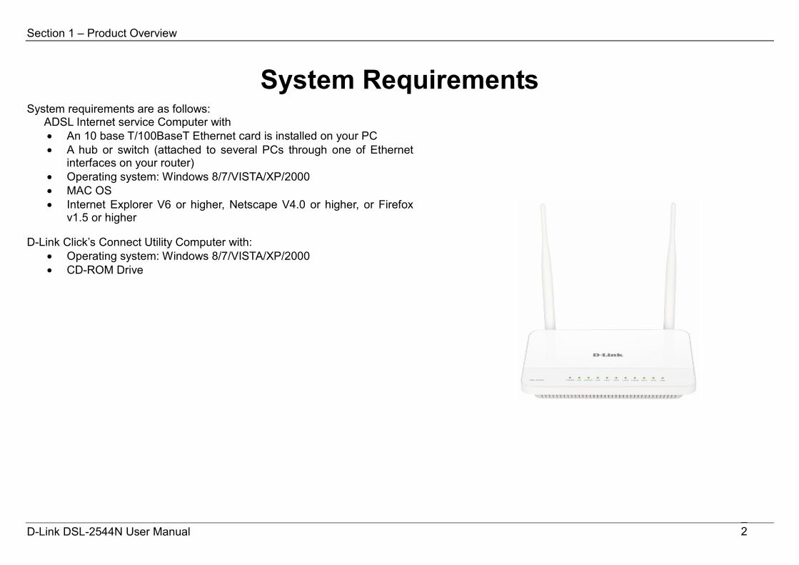
System Requirements System requirements are as follows:
ADSL Internet service Computer with • An 10 base T/100BaseT Ethernet card is installed on your PC • A hub or switch (attached to several PCs through one of Ethernet
interfaces on your router) • Operating system: Windows 8/7/VISTA/XP/2000 • MAC OS • Internet Explorer V6 or higher, Netscape V4.0 or higher, or Firefox
v1.5 or higher D-Link Click’s Connect Utility Computer with:
• Operating system: Windows 8/7/VISTA/XP/2000 • CD-ROM Drive
D-Link DSL-2544N User Manual 2

Section 1 – Product Overview 1
Features The device supports the following features:
• Various line modes • External PPPoE dial-up access • Internal PPPoE/PPPoA dial-up access • 1483Bridged/1483Routed with dynamic IP or static IP • Dual band wireless network (2.4G and 5G). • Multiple PVCs (the number of PVCs support is eight) • DHCP server/relay • Static route • Network Address Translation(NAT) • DMZ • Virtual Server • Universal plug and play (UPnP) • Dynamic Domain Name Server(DDNS) • One-level password and us123 • ername • Network Time Protocol(NTP) • Firmware upgrading through Web, TFTP, or FTP • Resetting to the factory defaults through Reset button or Web • Diagnostic test • Web interface • Telnet CLI • IP/MAC/URL Filter • Application layer service • QoS • Port binding • Ethernet uplink • 3G WAN service
D-Link DSL-2544N User Manual 3
Section 2 – Installation
Installation This section will walk you through the installation process. Placement of the Router is very important. Do not place the Router in an enclosed area such as a closet, cabinet or in the attic or garage.
Before You Begin Please read and make sure you understand all the prerequisites for proper installation of your new Router. Have all the necessary information and equipment on hand before beginning the installation.
Installation Notes In order to establish a connection to the Internet it will be necessary to provide information to the Router that will be stored in its memory. For some users, only their account information (Username and Password) is required. For others, various parameters that control and define the Internet connection will be required. You can print out the two pages below and use the tables to list this information. This way you have a hard copy of all the information needed to setup the Router. If it is necessary to reconfigure the device, all the necessary information can be easily accessed. Be sure to keep this information safe and private.
Low Pass Filters Since ADSL and telephone services share the same copper wiring to carry their respective signals, a filtering mechanism may be necessary to avoid mutual interference. A low pass filter device can be installed for each telephone that shares the line with the ADSL line. These filters are easy to install passive devices that connect to the ADSL device and/or telephone using a standard telephone cable. Ask your service provider for more information about the use of low pass filters with your installation.
Operating Systems The DSL-2544N uses an HTML-based web interface for setup and management. The web configuration manager may be accessed using any operating system capable of running web browser software, including Windows 98 SE, Windows ME, Windows 2000, Windows XP, and Windows Vista.
D-Link DSL-2544N User Manual 4

Section 2 – Installation
Web Browser Any common web browser can be used to configure the Router using the web configuration management software. The program is designed to work best with more recently released browsers such as Opera, Microsoft Internet Explorer® version 6.0, Netscape Navigator® version 6.2.3, or later versions. The web browser must have JavaScript enabled. JavaScript is enabled by default on many browsers. Make sure JavaScript has not been disabled by other software (such as virus protection or web user security packages) that may be running on your computer. Ethernet Port (NIC Adapter) Any computer that uses the Router must be able to connect to it through the Ethernet port on the Router. This connection is an Ethernet connection and therefore requires that your computer be equipped with an Ethernet port as well. Most notebook computers are now sold with an Ethernet port already installed. Likewise, most fully assembled desktop computers come with an Ethernet NIC adapter as standard. If your computer does not have an Ethernet port, you must install an Ethernet NIC adapter before you can use the Router. If you need to install an adapter, follow the installation instructions that come with the Ethernet NIC adapter.
Additional Software It may be necessary to install software on your computer that enables the computer to access the Internet. Additional software must be installed if you are using the device as a simple bridge. For a bridged connection, the information needed to make and maintain the Internet connection is stored on another computer or gateway device, not in the Router itself.
If your ADSL service is delivered through a PPPoE or PPPoA connection, the information needed to establish and maintain the Internet connection can be stored in the Router. In this case, it is not necessary to install software on your computer. It may however be necessary to change some settings in the device, including account information used to identify and verify the connection.
All connections to the Internet require a unique global IP address. For bridged connections, the global IP settings must reside in a TCP/IP enabled device on the LAN side of the bridge, such as a PC, a server, a gateway device, such as a router, or similar firewall hardware. The IP address can be assigned in a number of ways. Your network service provider will give you instructions about any additional connection software or NIC configuration that may be required.
D-Link DSL-2544N User Manual 5

Section 2 – Installation
Information you will need from your ADSL service provider Username This is the Username used to log on to your ADSL service provider’s network. Your ADSL service provider uses this to identify your account. Password This is the Password used, in conjunction with the Username above, to log on to your ADSL service provider’s network. This is used to verify the identity of your account. WAN Setting / Connection Type These settings describe the method your ADSL service provider uses to transport data between the Internet and your computer. Most users will use the default settings. You may need to specify one of the following WAN Setting and Connection Type configurations (Connection Type settings listed in parenthesis):
PPPoE/PPPoA (PPPoE LLC, PPPoA LLC or PPPoA VC-Mux) Bridge Mode (1483 Bridged IP LLC or 1483 Bridged IP VC Mux) IPoA/MER (Static IP Address) (Bridged IP LLC, 1483 Bridged IP VC Mux, 1483 Routed IP LLC, 1483 Routed IP VC-Mux or IPoA) MER (Dynamic IP Address) (1483 Bridged IP LLC or 1483 Bridged IP VC-Mux)
Modulation Type ADSL uses various standardized modulation techniques to transmit data over the allotted signal frequencies. Some users may need to change the type of modulation used for their service. The default DSL modulation (ADSL2+ Multi-Mode) used for the Router automatically detects all types of ADSL, ADSL2 and ADSL2+ modulation. Security Protocol This is the method your ADSL service provider will use to verify your Username and Password when you log on to their network. Your Router supports the PAP and CHAP protocols. VPI Most users will not be required to change this setting. The Virtual Path Identifier (VPI) is used in conjunction with the Virtual Channel Identifier (VCI) to identify the data path between your ADSL service provider’s network and your computer. If you are setting up the Router for multiple virtual connections, you will need to configure the VPI and VCI as instructed by your ADSL service provider for the additional connections. This setting can be changed in the WAN Settings window of the web management interface. VCI Most users will not be required to change this setting. The Virtual Channel Identifier (VCI) is used in conjunction with the VPI to identify the data path between your ADSL service provider’s network and your computer. If you are setting up the Router for multiple virtual connections, you will need to configure the VPI and VCI as instructed by your ADSL service provider for the additional connections. This setting can be changed in the WAN Setup window of the web management interface.
D-Link DSL-2544N User Manual 6
Section 2 – Installation
Information you will need about your DSL-2544N ADSL Router
Username This is the Username needed to access the Router’s management interface. When you attempt to connect to the device through a web browser you will be prompted to enter this Username. The default Username for the Router is “admin.” The user cannot change this.
Password This is the Password you will be prompted to enter when you access the Router’s management interface. The default Password is “admin.” The user may change this.
LAN IP addresses for the DSL-2544N This is the IP address you will enter into the Address field of your web browser to access the Router’s configuration graphical user interface (GUI) using a web browser. The default IP address is 192.168.1.1. This may be changed to suit any IP address scheme the user desires. This address will be the base IP address used for DHCP service on the LAN when DHCP is enabled.
LAN Subnet Mask for the DSL-2544N This is the subnet mask used by the DSL-2544N and will be used throughout your LAN. The default subnet mask is 255.255.255.0. This can be changed later.
D-Link DSL-2544N User Manual 7
Section 2 – Installation
Information you will need about your LAN or computer Ethernet NIC If your computer has an Ethernet NIC, you can connect the DSL-2544N to the Ethernet port using an Ethernet cable. You can also use the Ethernet ports on the DSL-2544N to connect to other computers or Ethernet devices.
DHCP Client status Your DSL-2544N ADSL Router is configured, by default, to be a DHCP server. This means that it can assign an IP address, subnet mask and a default gateway address to computers on your LAN. The default range of IP addresses the DSL-2544N will assign are from 192.168.1.2 to 192.168.1.254. Your computer (or computers) needs to be configured to obtain an IP address automatically (that is, they need to be configured as DHCP clients.)
It is recommended that you collect and record this information here, or in some other secure place, in case you have to re-configure your ADSL connection in the future.
Once you have the above information, you are ready to setup and configure your DSL-2544N ADSL Router.
D-Link DSL-2544N User Manual 8
Section 2 – Installation
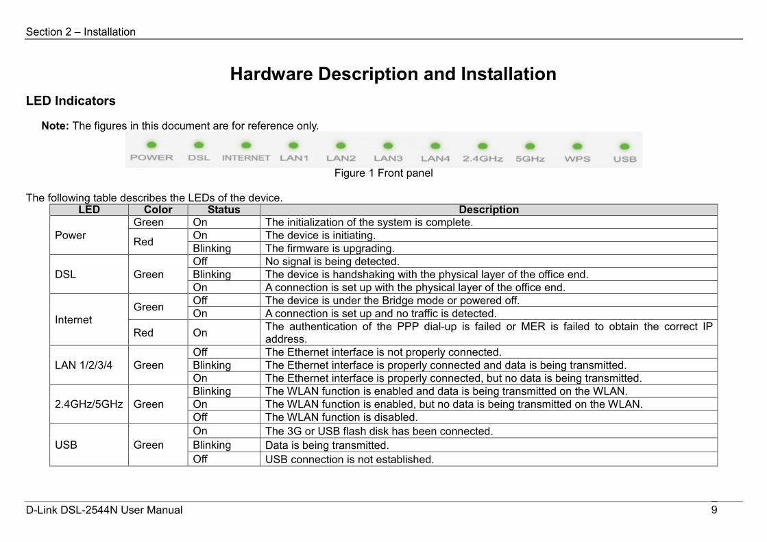
Hardware Description and Installation LED Indicators
Note: The figures in this document are for reference only.
Figure 1 Front panel
The following table describes the LEDs of the device.
LED Color Status Description
Power Green On The initialization of the system is complete.
Red On The device is initiating. Blinking The firmware is upgrading.
DSL Green Off No signal is being detected. Blinking The device is handshaking with the physical layer of the office end. On A connection is set up with the physical layer of the office end.
Internet Green Off The device is under the Bridge mode or powered off.
On A connection is set up and no traffic is detected.
Red On The authentication of the PPP dial-up is failed or MER is failed to obtain the correct IP address.
LAN 1/2/3/4 Green Off The Ethernet interface is not properly connected. Blinking The Ethernet interface is properly connected and data is being transmitted. On The Ethernet interface is properly connected, but no data is being transmitted.
2.4GHz/5GHz Green Blinking The WLAN function is enabled and data is being transmitted on the WLAN. On The WLAN function is enabled, but no data is being transmitted on the WLAN. Off The WLAN function is disabled.
USB Green On The 3G or USB flash disk has been connected. Blinking Data is being transmitted. Off USB connection is not established.
D-Link DSL-2544N User Manual 9
Section 2 – Installation
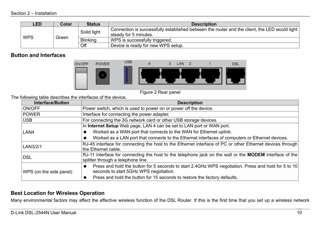
LED Color Status Description
WPS Green Solid light Connection is successfully established between the router and the client, the LED would light
steady for 5 minutes. Blinking WPS is successfully triggered. Off Device is ready for new WPS setup.
Button and Interfaces
Figure 2 Rear panel
The following table describes the interfaces of the device. Interface/Button Description
ON/OFF Power switch, which is used to power on or power off the device. POWER Interface for connecting the power adapter. USB For connecting the 3G network card or other USB storage devices.
LAN4 In Internet Setup Web page, LAN 4 can be set to LAN port or WAN port. Worked as a WAN port that connects to the WAN for Ethernet uplink. Worked as a LAN port that connects to the Ethernet interfaces of computers or Ethernet devices.
LAN3/2/1 RJ-45 interface for connecting the host to the Ethernet interface of PC or other Ethernet devices through the Ethernet cable.
DSL RJ-11 interface for connecting the host to the telephone jack on the wall or the MODEM interface of the splitter through a telephone line.
WPS (on the side panel) Press and hold the button for 5 seconds to start 2.4GHz WPS negotiation. Press and hold for 5 to 10
seconds to start 5GHz WPS negotiation. Press and hold the button for 15 seconds to restore the factory defaults.
Best Location for Wireless Operation Many environmental factors may affect the effective wireless function of the DSL Router. If this is the first time that you set up a wireless network
D-Link DSL-2544N User Manual 10
Section 2 – Installation
device, read the following information: The access point can be placed on a shelf or desktop, ideally you should be able to see the LED indicators in the front, as you may need to view them for troubleshooting. Designed to go up to 100 meters indoors and up to 300 meters outdoors, wireless LAN lets you access your network from anywhere you want. However, the numbers of walls, ceilings, or other objects that the wireless signals must pass through limit signal range. Typical ranges vary depending on types of materials and background RF noise in your home or business.
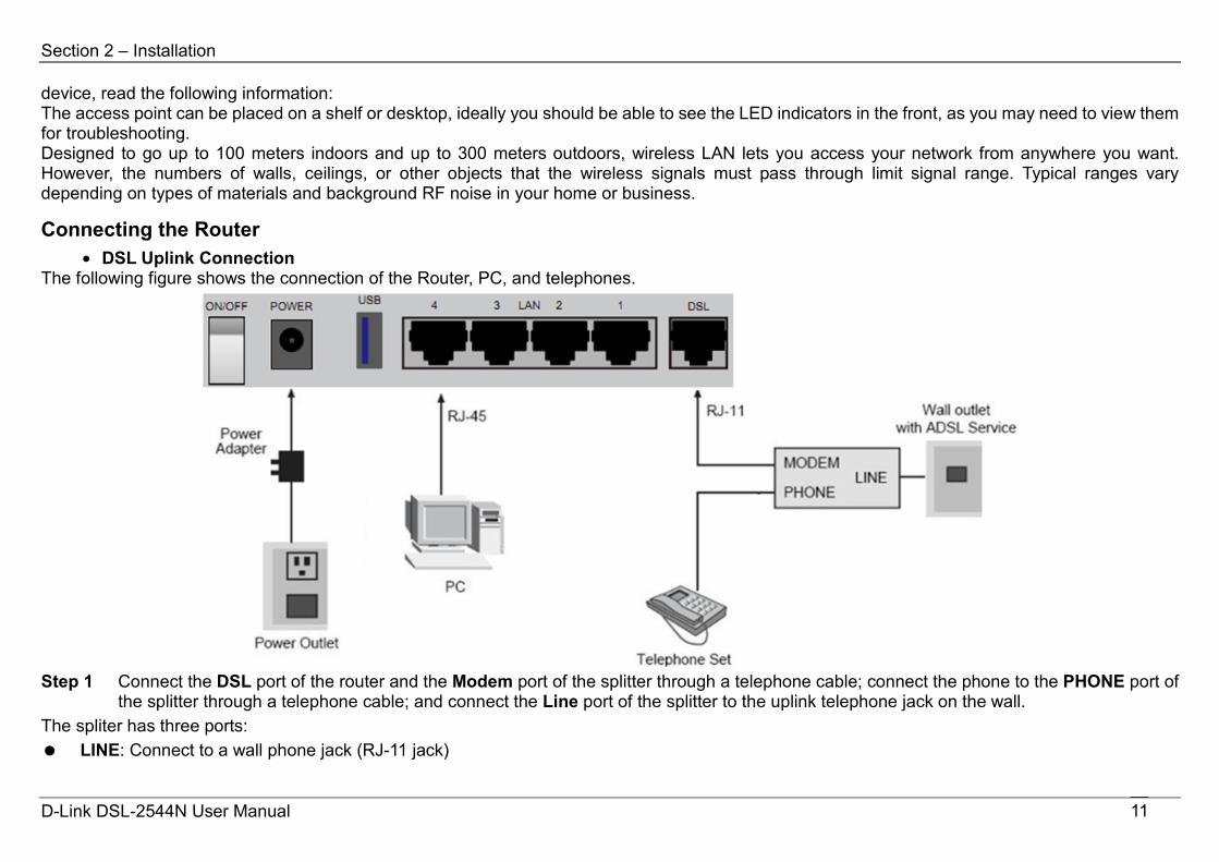
Connecting the Router • DSL Uplink Connection
The following figure shows the connection of the Router, PC, and telephones.
Step 1 Connect the DSL port of the router and the Modem port of the splitter through a telephone cable; connect the phone to the PHONE port of
the splitter through a telephone cable; and connect the Line port of the splitter to the uplink telephone jack on the wall. The spliter has three ports: LINE: Connect to a wall phone jack (RJ-11 jack)
D-Link DSL-2544N User Manual 11
Section 2 – Installation
MODEM: Connect to the DSLinterface of the router PHONE: Connect to a telephone set Step 2 Connect the LAN port of the router to the network interface card (NIC) of the PC through an Ethernet cable (MDI/MDIX). Step 3 Plug the power adapter to the wall outlet and then connect the other end of it to the POWER port of the route.
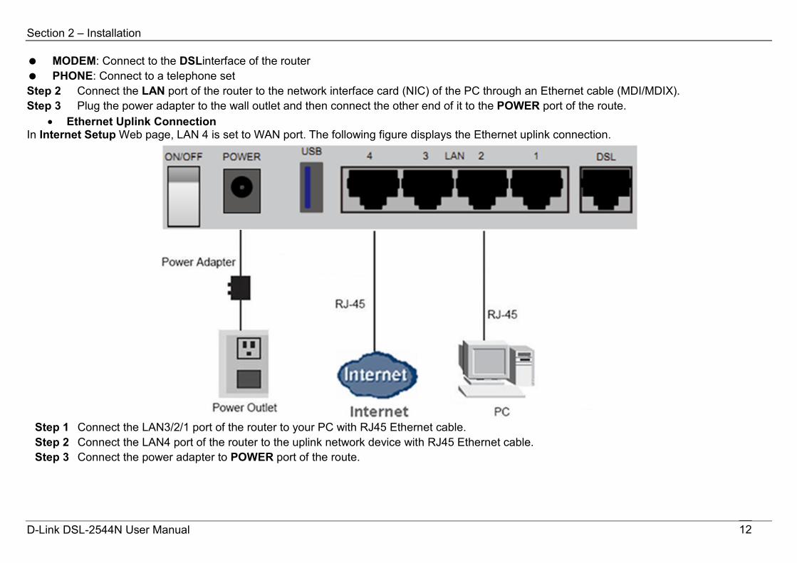
• Ethernet Uplink Connection In Internet Setup Web page, LAN 4 is set to WAN port. The following figure displays the Ethernet uplink connection.
Step 1 Connect the LAN3/2/1 port of the router to your PC with RJ45 Ethernet cable. Step 2 Connect the LAN4 port of the router to the uplink network device with RJ45 Ethernet cable. Step 3 Connect the power adapter to POWER port of the route.
D-Link DSL-2544N User Manual 12

Section 3 – Web Configuration
Web Configuration This chapter describes how to use Web-based management of the DSL router, which allows you to configure and control all of DSL router features and system parameters in a user-friendly GUI.
Accessing the Router Configuring IP Address of the Network Card Configure TCP/IP properties of your network card to Obtain an IP address automatically from modem, or set the IP address of the computer with the same network mask of the modem. For example, if the IP address of Router is 192.168.1.1/255.255.255.0, you can set the IP address of the computer to 192.168.1.x/255.255.255.0. The range for x is from 3 to 254. The following description is a detail “How-To” user guide and is prepared for first time users.
Step 1 Open the Internet Explorer (IE) browser, and then go to http://192.168.1.1.
Step 2 The Login page is shown as the figure appears on the right. Select admin from the drop-down list of username and enter the password.
The password is admin.
D-Link DSL-2544N User Manual 13

Section 3 – Web Configuration
SETUP Wizard Wizard enables fast and accurate configuration of Internet connection and other important parameters. The following sections describe these various configuration parameters. When subscribing to a broadband service, you should be aware of the method, by which you are connected to the Internet. The connection type of your physical WAN device can be DSL or Ethernet. Technical information about the properties of your Internet connection is provided by your Internet service provider (ISP). For example, your ISP should inform you whether you are connected to the Internet using a static or dynamic IP address, or the protocol, such as PPPoA or PPPoE, that you use to communicate over the Internet.
Step 1 Choose SETUP > Wizard. The page is shown as the figure appears on the right. Note: When you logging into Web page first time, the Wizard page appears directly.
Step 2 Click Setup Wizard. The page is shown as the figure appears on the
right.
D-Link DSL-2544N User Manual 14
Section 3 – Web Configuration
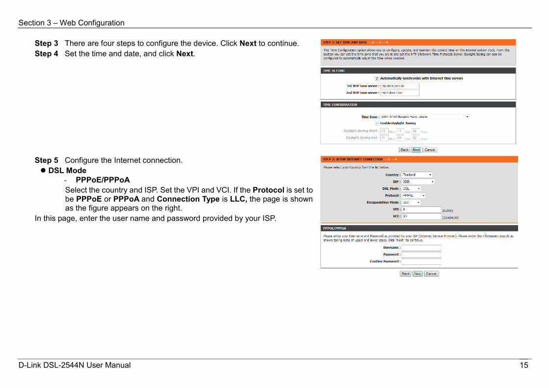
Step 3 There are four steps to configure the device. Click Next to continue. Step 4 Set the time and date, and click Next.
Step 5 Configure the Internet connection. DSL Mode
- PPPoE/PPPoA Select the country and ISP. Set the VPI and VCI. If the Protocol is set to be PPPoE or PPPoA and Connection Type is LLC, the page is shown as the figure appears on the right.
In this page, enter the user name and password provided by your ISP.
D-Link DSL-2544N User Manual 15

Section 3 – Web Configuration
- Static IP If the internet service you subscribed is Static IP, the Protocol is set to be Static IP, the page shown as the figure appears on the right.
In this page, enter the IP Address, Subnet Mask, Default Gateway and Primary DNS Server provided by your ISP. If the Protocol is set to be Dynamic IP and Bridge, the content of the page will be slightly different. Ethernet Mode
If DSL mode is set to Ethernet, the protocol includes: Bridge, Dynamic IP, Static IP, and PPPoE. In PPPoE protocol, enter the user name and password provided by your ISP. After settings, click Next to go to the next page.
D-Link DSL-2544N User Manual 16
Section 3 – Web Configuration
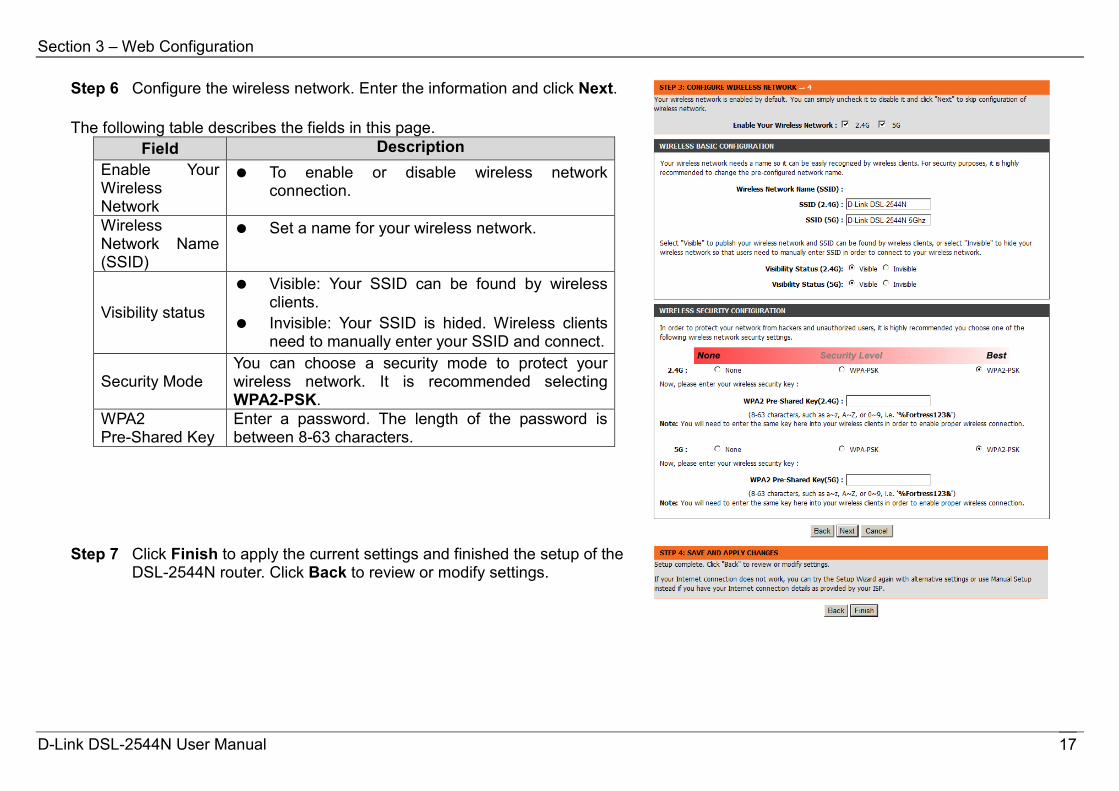
Step 6 Configure the wireless network. Enter the information and click Next. The following table describes the fields in this page.
Field Description Enable Your Wireless Network
To enable or disable wireless network connection.
Wireless Network Name (SSID)
Set a name for your wireless network.
Visibility status
Visible: Your SSID can be found by wireless clients.
Invisible: Your SSID is hided. Wireless clients need to manually enter your SSID and connect.
Security Mode You can choose a security mode to protect your wireless network. It is recommended selecting WPA2-PSK.
WPA2 Pre-Shared Key
Enter a password. The length of the password is between 8-63 characters.
Step 7 Click Finish to apply the current settings and finished the setup of the
DSL-2544N router. Click Back to review or modify settings.
D-Link DSL-2544N User Manual 17
Section 3 – Web Configuration
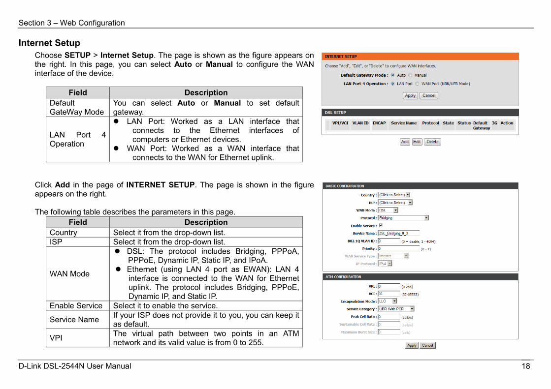
Internet Setup Choose SETUP > Internet Setup. The page is shown as the figure appears on the right. In this page, you can select Auto or Manual to configure the WAN interface of the device.
Field Description Default GateWay Mode
You can select Auto or Manual to set default gateway.
LAN Port 4 Operation
LAN Port: Worked as a LAN interface that connects to the Ethernet interfaces of computers or Ethernet devices.
WAN Port: Worked as a WAN interface that connects to the WAN for Ethernet uplink.
Click Add in the page of INTERNET SETUP. The page is shown in the figure appears on the right. The following table describes the parameters in this page.
Field Description Country Select it from the drop-down list. ISP Select it from the drop-down list.
WAN Mode
DSL: The protocol includes Bridging, PPPoA, PPPoE, Dynamic IP, Static IP, and IPoA.
Ethernet (using LAN 4 port as EWAN): LAN 4 interface is connected to the WAN for Ethernet uplink. The protocol includes Bridging, PPPoE, Dynamic IP, and Static IP.
Enable Service Select it to enable the service.
Service Name If your ISP does not provide it to you, you can keep it as default.
VPI The virtual path between two points in an ATM network and its valid value is from 0 to 255.
D-Link DSL-2544N User Manual 18
Section 3 – Web Configuration
VCI The virtual channel between two points in an ATM network, ranging from 32 to 65535 (0 to 31 is reserved for local management of ATM traffic).
Encapsulation Mode
Select the method of encapsulation provided by your ISP. You can select from the drop-down list.
Service Category
You can select from the drop-down list.
After setting, click Apply to save the settings.
D-Link DSL-2544N User Manual 19
Section 3 – Web Configuration
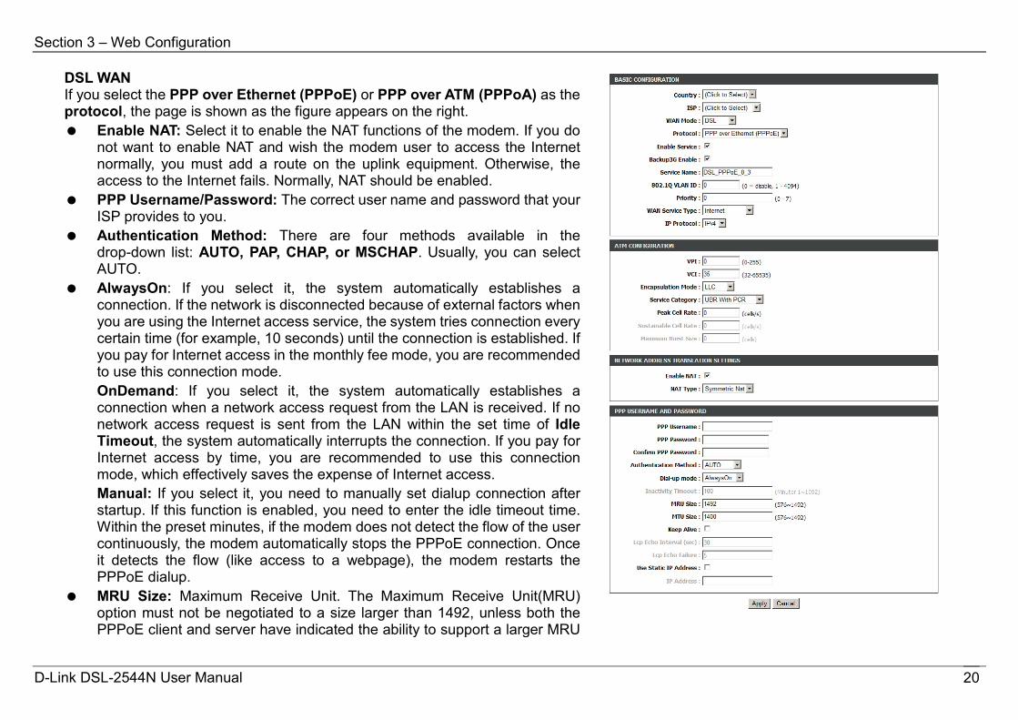
DSL WAN If you select the PPP over Ethernet (PPPoE) or PPP over ATM (PPPoA) as the protocol, the page is shown as the figure appears on the right. Enable NAT: Select it to enable the NAT functions of the modem. If you do
not want to enable NAT and wish the modem user to access the Internet normally, you must add a route on the uplink equipment. Otherwise, the access to the Internet fails. Normally, NAT should be enabled.
PPP Username/Password: The correct user name and password that your ISP provides to you.
Authentication Method: There are four methods available in the drop-down list: AUTO, PAP, CHAP, or MSCHAP. Usually, you can select AUTO.
AlwaysOn: If you select it, the system automatically establishes a connection. If the network is disconnected because of external factors when you are using the Internet access service, the system tries connection every certain time (for example, 10 seconds) until the connection is established. If you pay for Internet access in the monthly fee mode, you are recommended to use this connection mode. OnDemand: If you select it, the system automatically establishes a connection when a network access request from the LAN is received. If no network access request is sent from the LAN within the set time of Idle Timeout, the system automatically interrupts the connection. If you pay for Internet access by time, you are recommended to use this connection mode, which effectively saves the expense of Internet access. Manual: If you select it, you need to manually set dialup connection after startup. If this function is enabled, you need to enter the idle timeout time. Within the preset minutes, if the modem does not detect the flow of the user continuously, the modem automatically stops the PPPoE connection. Once it detects the flow (like access to a webpage), the modem restarts the PPPoE dialup.
MRU Size: Maximum Receive Unit. The Maximum Receive Unit(MRU) option must not be negotiated to a size larger than 1492, unless both the PPPoE client and server have indicated the ability to support a larger MRU
D-Link DSL-2544N User Manual 20
Section 3 – Web Configuration
in the PPPoE Discovery Stage. MTU Size: Maximum Transmission Unit. Sometimes, you must modify this
function to access network successfully. Keep Alive: Enable or disable the PPPoE dial-up to keep alive. Use Static IP Address: If this function is disabled, the modem obtains an
IP address assigned by an uplink equipment such as BAS, through PPPoE dial-up. If this function is enabled, the modem uses this IP address as the WAN IP address.
For other entries which are not mentioned above, you can keep them as defaults.
D-Link DSL-2544N User Manual 21
Section 3 – Web Configuration
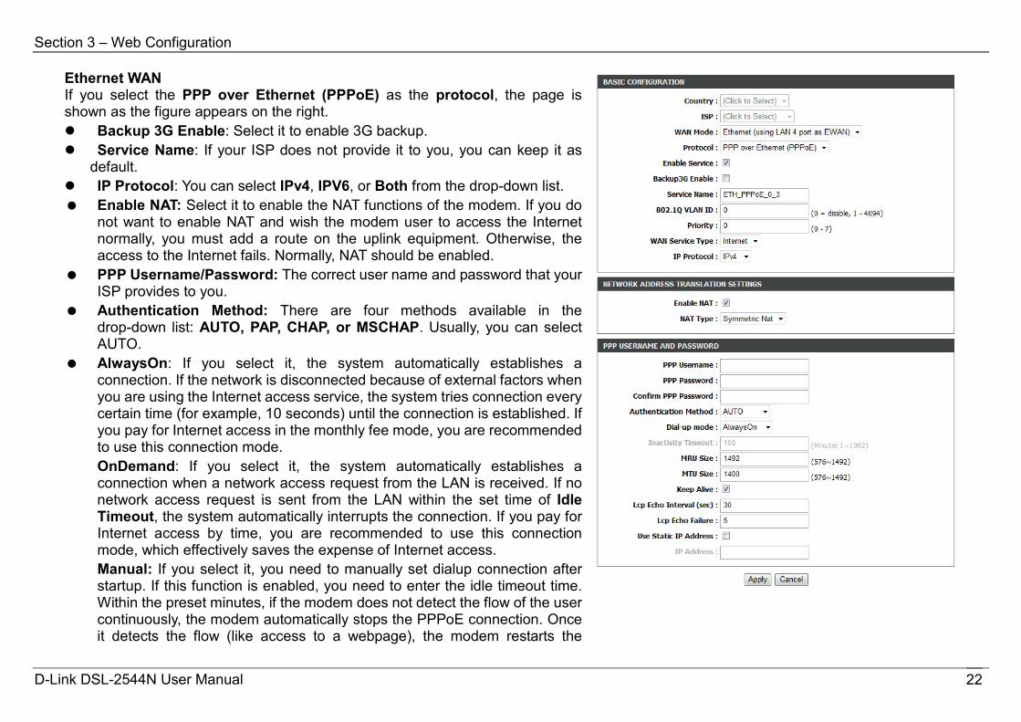
Ethernet WAN If you select the PPP over Ethernet (PPPoE) as the protocol, the page is shown as the figure appears on the right. Backup 3G Enable: Select it to enable 3G backup. Service Name: If your ISP does not provide it to you, you can keep it as
default. IP Protocol: You can select IPv4, IPV6, or Both from the drop-down list. Enable NAT: Select it to enable the NAT functions of the modem. If you do
not want to enable NAT and wish the modem user to access the Internet normally, you must add a route on the uplink equipment. Otherwise, the access to the Internet fails. Normally, NAT should be enabled.
PPP Username/Password: The correct user name and password that your ISP provides to you.
Authentication Method: There are four methods available in the drop-down list: AUTO, PAP, CHAP, or MSCHAP. Usually, you can select AUTO.
AlwaysOn: If you select it, the system automatically establishes a connection. If the network is disconnected because of external factors when you are using the Internet access service, the system tries connection every certain time (for example, 10 seconds) until the connection is established. If you pay for Internet access in the monthly fee mode, you are recommended to use this connection mode. OnDemand: If you select it, the system automatically establishes a connection when a network access request from the LAN is received. If no network access request is sent from the LAN within the set time of Idle Timeout, the system automatically interrupts the connection. If you pay for Internet access by time, you are recommended to use this connection mode, which effectively saves the expense of Internet access. Manual: If you select it, you need to manually set dialup connection after startup. If this function is enabled, you need to enter the idle timeout time. Within the preset minutes, if the modem does not detect the flow of the user continuously, the modem automatically stops the PPPoE connection. Once it detects the flow (like access to a webpage), the modem restarts the
D-Link DSL-2544N User Manual 22
Section 3 – Web Configuration
PPPoE dialup. MRU Size: Maximum Receive Unit. The Maximum Receive Unit(MRU)
option must not be negotiated to a size larger than 1492, unless both the PPPoE client and server have indicated the ability to support a larger MRU in the PPPoE Discovery Stage.
MTU Size: Maximum Transmission Unit. Sometimes, you must modify this function to access network successfully.
Keep Alive: Enable or disable the PPPoE dial-up to keep alive. Use Static IP Address: If this function is disabled, the modem obtains an
IP address assigned by an uplink equipment such as BAS, through PPPoE dial-up. If this function is enabled, the modem uses this IP address as the WAN IP address.
For other entries which are not mentioned above, you can keep them as defaults. After proper settings, click Apply to save the settings.
D-Link DSL-2544N User Manual 23
Section 3 – Web Configuration
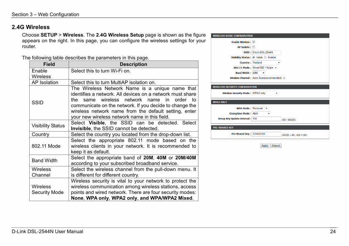
2.4G Wireless Choose SETUP > Wireless. The 2.4G Wireless Setup page is shown as the figure appears on the right. In this page, you can configure the wireless settings for your router. The following table describes the parameters in this page.
Field Description Enable Wireless
Select this to turn Wi-Fi on.
AP Isolation Select this to turn MultiAP isolation on.
SSID
The Wireless Network Name is a unique name that identifies a network. All devices on a network must share the same wireless network name in order to communicate on the network. If you decide to change the wireless network name from the default setting, enter your new wireless network name in this field.
Visibility Status Select Visible, the SSID can be detected. Select Invisible, the SSID cannot be detected.
Country Select the country you located from the drop-down list.
802.11 Mode Select the appropriate 802.11 mode based on the wireless clients in your network. It is recommended to keep it as default.
Band Width Select the appropriate band of 20M, 40M or 20M/40M according to your subscribed broadband service.
Wireless Channel
Select the wireless channel from the pull-down menu. It is different for different country.
Wireless Security Mode
Wireless security is vital to your network to protect the wireless communication among wireless stations, access points and wired network. There are four security modes: None, WPA only, WPA2 only, and WPA/WPA2 Mixed.
D-Link DSL-2544N User Manual 24
Section 3 – Web Configuration
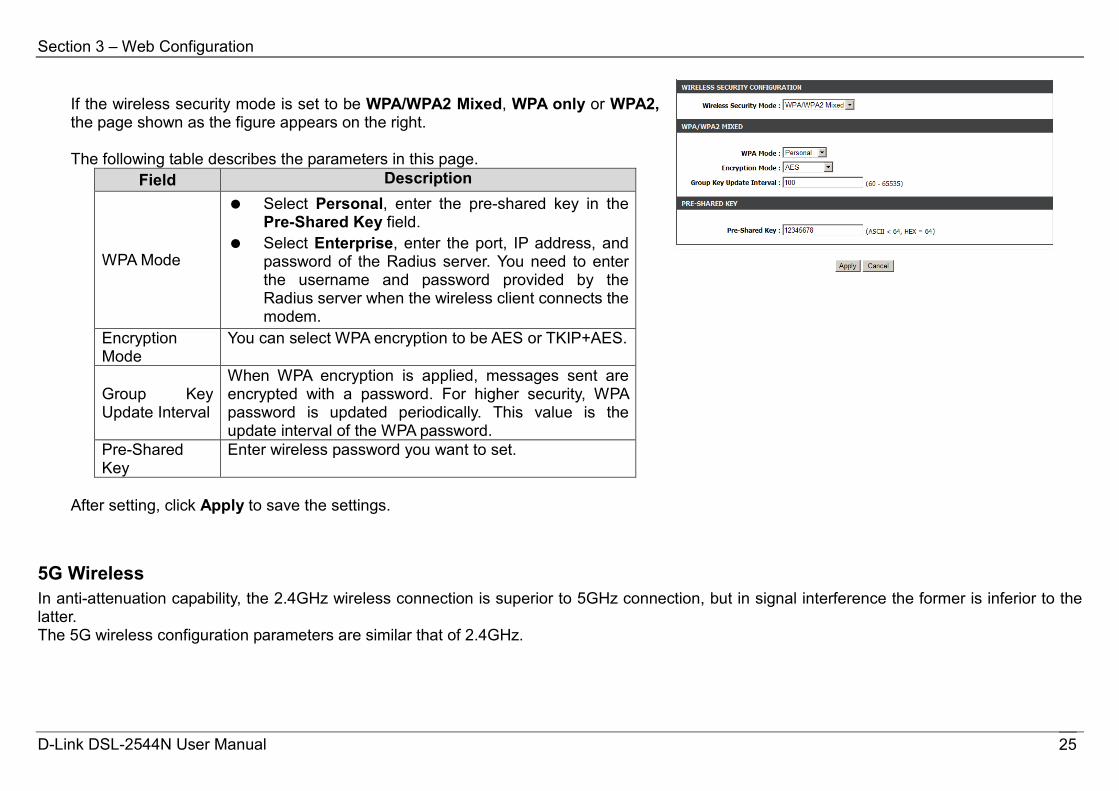
If the wireless security mode is set to be WPA/WPA2 Mixed, WPA only or WPA2, the page shown as the figure appears on the right. The following table describes the parameters in this page.
Field Description
WPA Mode
Select Personal, enter the pre-shared key in the Pre-Shared Key field.
Select Enterprise, enter the port, IP address, and password of the Radius server. You need to enter the username and password provided by the Radius server when the wireless client connects the modem.
Encryption Mode
You can select WPA encryption to be AES or TKIP+AES.
Group Key Update Interval
When WPA encryption is applied, messages sent are encrypted with a password. For higher security, WPA password is updated periodically. This value is the update interval of the WPA password.
Pre-Shared Key
Enter wireless password you want to set.
After setting, click Apply to save the settings.
5G Wireless In anti-attenuation capability, the 2.4GHz wireless connection is superior to 5GHz connection, but in signal interference the former is inferior to the latter. The 5G wireless configuration parameters are similar that of 2.4GHz.
D-Link DSL-2544N User Manual 25
Section 3 – Web Configuration
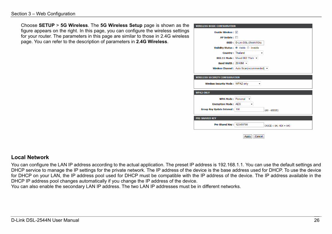
Choose SETUP > 5G Wireless. The 5G Wireless Setup page is shown as the figure appears on the right. In this page, you can configure the wireless settings for your router. The parameters in this page are similar to those in 2.4G wireless page. You can refer to the description of parameters in 2.4G Wireless.
Local Network You can configure the LAN IP address according to the actual application. The preset IP address is 192.168.1.1. You can use the default settings and DHCP service to manage the IP settings for the private network. The IP address of the device is the base address used for DHCP. To use the device for DHCP on your LAN, the IP address pool used for DHCP must be compatible with the IP address of the device. The IP address available in the DHCP IP address pool changes automatically if you change the IP address of the device. You can also enable the secondary LAN IP address. The two LAN IP addresses must be in different networks.
D-Link DSL-2544N User Manual 26
Section 3 – Web Configuration
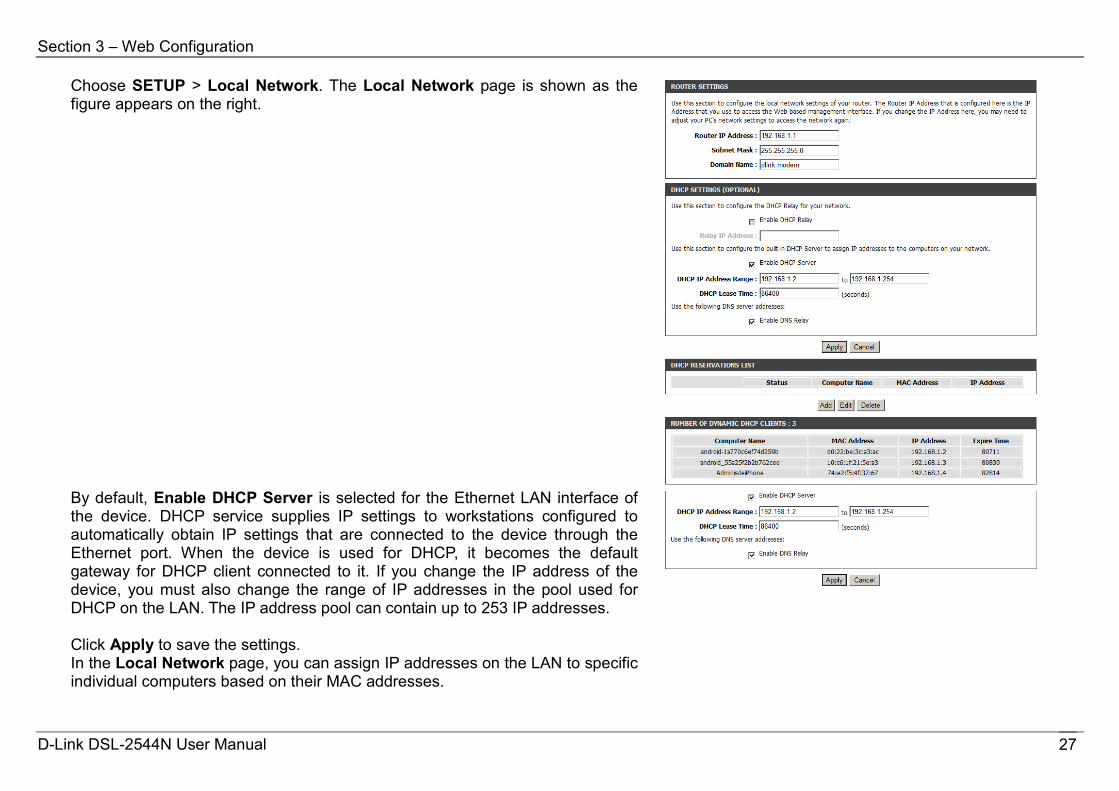
Choose SETUP > Local Network. The Local Network page is shown as the figure appears on the right.
By default, Enable DHCP Server is selected for the Ethernet LAN interface of the device. DHCP service supplies IP settings to workstations configured to automatically obtain IP settings that are connected to the device through the Ethernet port. When the device is used for DHCP, it becomes the default gateway for DHCP client connected to it. If you change the IP address of the device, you must also change the range of IP addresses in the pool used for DHCP on the LAN. The IP address pool can contain up to 253 IP addresses. Click Apply to save the settings. In the Local Network page, you can assign IP addresses on the LAN to specific individual computers based on their MAC addresses.
D-Link DSL-2544N User Manual 27

Section 3 – Web Configuration
Click Add to add static DHCP (optional). The page is shown as the figure appears on the right.
Check the box Enable to reserve the IP address for the designated PC with the configured MAC address. The Computer Name helps you to recognize the PC with the MAC address. For example, Father’s Laptop. Click Apply to save the settings.
After the DHCP reservation is saved, the DHCP reservations list displays the configuration.
D-Link DSL-2544N User Manual 28
Section 3 – Web Configuration
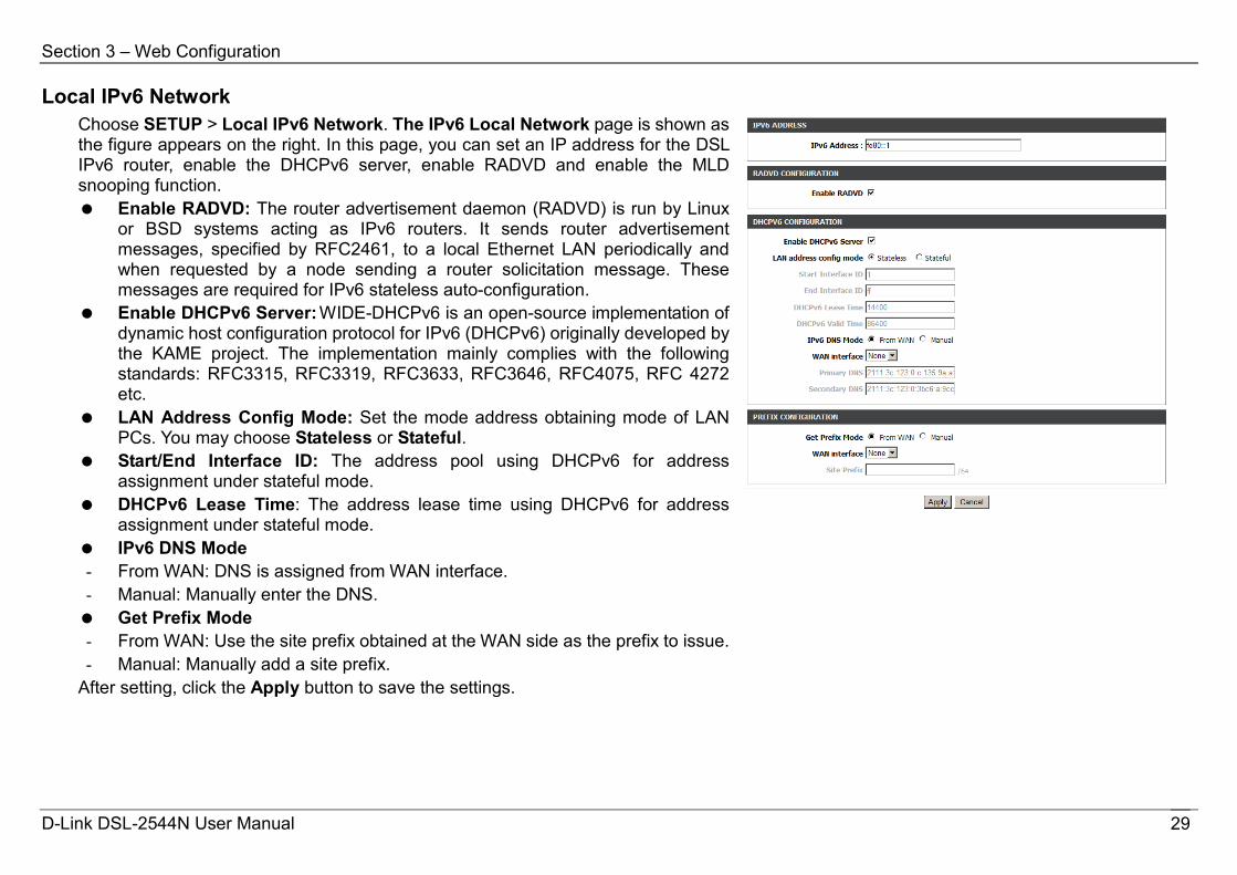
Local IPv6 Network Choose SETUP > Local IPv6 Network. The IPv6 Local Network page is shown as the figure appears on the right. In this page, you can set an IP address for the DSL IPv6 router, enable the DHCPv6 server, enable RADVD and enable the MLD snooping function. Enable RADVD: The router advertisement daemon (RADVD) is run by Linux
or BSD systems acting as IPv6 routers. It sends router advertisement messages, specified by RFC2461, to a local Ethernet LAN periodically and when requested by a node sending a router solicitation message. These messages are required for IPv6 stateless auto-configuration.
Enable DHCPv6 Server: WIDE-DHCPv6 is an open-source implementation of dynamic host configuration protocol for IPv6 (DHCPv6) originally developed by the KAME project. The implementation mainly complies with the following standards: RFC3315, RFC3319, RFC3633, RFC3646, RFC4075, RFC 4272 etc.
LAN Address Config Mode: Set the mode address obtaining mode of LAN PCs. You may choose Stateless or Stateful.
Start/End Interface ID: The address pool using DHCPv6 for address assignment under stateful mode.
DHCPv6 Lease Time: The address lease time using DHCPv6 for address assignment under stateful mode.
IPv6 DNS Mode - From WAN: DNS is assigned from WAN interface. - Manual: Manually enter the DNS. Get Prefix Mode - From WAN: Use the site prefix obtained at the WAN side as the prefix to issue. - Manual: Manually add a site prefix.
After setting, click the Apply button to save the settings.
D-Link DSL-2544N User Manual 29

Section 3 – Web Configuration
Time and Date Choose SETUP > Time and Date. The page is shown as the figure appears on the right. In the Time and Date page, you can configure, update, and maintain the correct time on the internal system clock. You can set the time zone that you are in and the network time protocol (NTP) server. You can also configure daylight saving to automatically adjust the time when needed.
Logout Choose SETUP > Logout. The page is shown as the figure appears on the right. In this page, you can log out of the configuration page.
D-Link DSL-2544N User Manual 30
Section 3 – Web Configuration
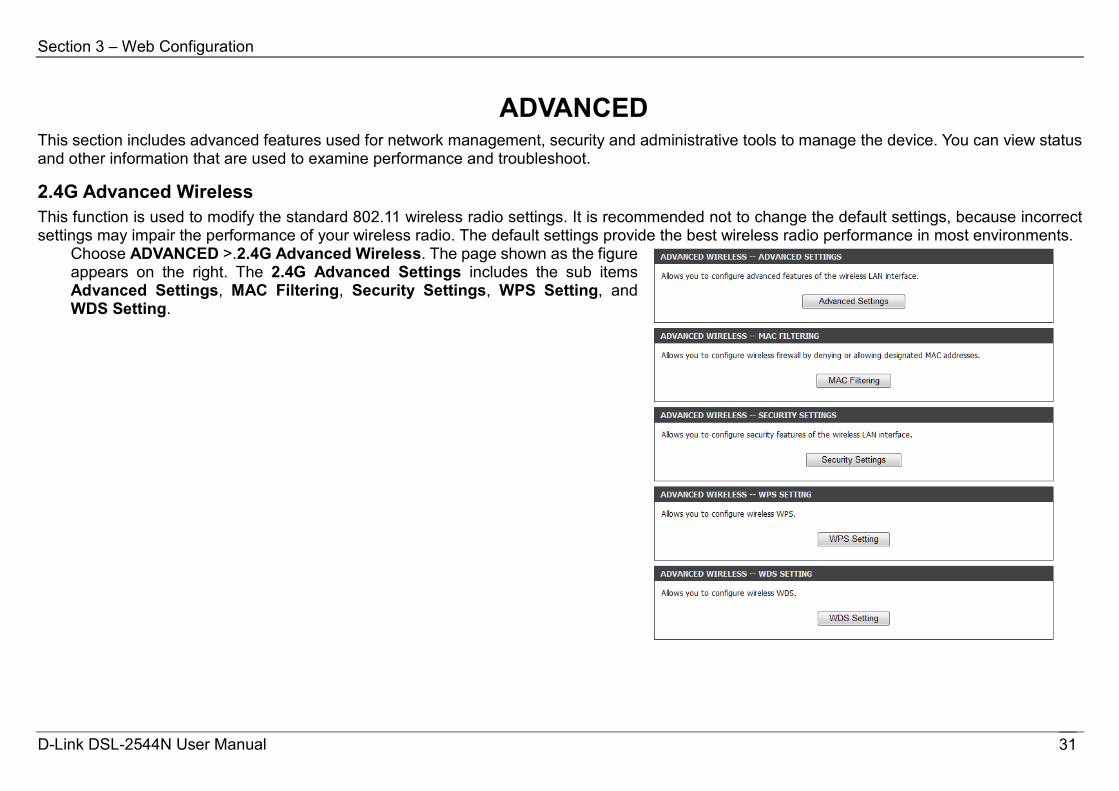
ADVANCED This section includes advanced features used for network management, security and administrative tools to manage the device. You can view status and other information that are used to examine performance and troubleshoot.
2.4G Advanced Wireless This function is used to modify the standard 802.11 wireless radio settings. It is recommended not to change the default settings, because incorrect settings may impair the performance of your wireless radio. The default settings provide the best wireless radio performance in most environments.
Choose ADVANCED >.2.4G Advanced Wireless. The page shown as the figure appears on the right. The 2.4G Advanced Settings includes the sub items Advanced Settings, MAC Filtering, Security Settings, WPS Setting, and WDS Setting.
D-Link DSL-2544N User Manual 31

Section 3 – Web Configuration
Advanced Settings In the 2.4G Advanced Wireless page, click Advanced Settings, the page is shown as the figures appear on the right. In this page, you can configure the parameters of wireless LAN clients that may connect to the device. Enable Wireless: Select the check box to turn the Wi-Fi on. Transmit Power: Adjust the transmission range here. This tool can be
helpful for security purposes if you wish to limit the transmission range. Beacon Period: A beacon is a packet of information that is sent from a
connected device to all other devices where it announces its availability and readiness. A beacon period is a period of time (sent with the beacon) before sending the beacon again. The beacon period may be adjusted in milliseconds (ms). Default (100) is recommended.
RTS Threshold: This value should remain at its default setting of 2347. Should you encounter inconsistent data flow, only minor reductions are recommended. Should you encounter inconsistent data flow, only minor reduction of the default value, 2347, is recommended. If a network packet is smaller than the preset RTS threshold size, the RTS/CTS mechanism will not be enabled. The Router sends Request to Send (RTS) frames to a particular receiving station and negotiates the sending of a data frame. After receiving an RTS, the wireless station responds with a Clear to Send (CTS) frame to acknowledge the right to begin transmission. The RTS Threshold value should remain at its default value of 2347.
Fragmentation Threshold: Packets that are larger than this threshold are fragmented into multiple packets. Try to increase the fragmentation threshold if you encounter high packet error rates. Do not set the threshold too low, since this can result in reduced networking performance.
DTIM Interval: (Delivery Traffic Indication Message) Enter a value between 1 and 255 for the Delivery Traffic Indication Message (DTIM.) A DTIM is a countdown informing clients of the next window for listening to broadcast and multicast messages.
SSID: The Wireless Network Name is a unique name that identifies a network. All devices on a network must share the same wireless network name in order to communicate on the network. If you decide to change the
D-Link DSL-2544N User Manual 32
Section 3 – Web Configuration
wireless network name from the default setting, enter your new wireless network name in this field.
Visibility Status: You can select Visible or Invisible. User Isolation: When many clients connect to the same access point, they
can access each other. If you want to disable the access between clients which connect the same access point, you can select on to enable this service.
Disable WMM Advertise: After enabling this option, the transmission performance multimedia of the voice and video data can be improved.
Click Apply to save the settings.
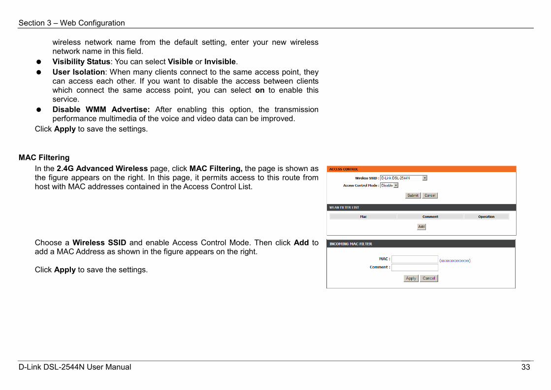
MAC Filtering In the 2.4G Advanced Wireless page, click MAC Filtering, the page is shown as the figure appears on the right. In this page, it permits access to this route from host with MAC addresses contained in the Access Control List.
Choose a Wireless SSID and enable Access Control Mode. Then click Add to add a MAC Address as shown in the figure appears on the right. Click Apply to save the settings.
D-Link DSL-2544N User Manual 33

Section 3 – Web Configuration
Security Settings In the Wireless Settings page, click Security Settings. The page is shown as the figure appears on the right. This page allows you to select a security mode. Note that depending on the network authentication that is selected, the page will change accordingly so additional fields can be configured for the specific security mode. Select SSID: Select the SSID that you want to configure from the drop-down list. For the description of Work Mode field, please refer to the description of Wireless Security Mode in 2.4G Wireless.
WPS Setting In the Wireless Settings page, click WPS Setting. The page shown as the figure appears on the right. In this page, you can configure Wi-Fi Protected Setup (WPS). Note: Before you configure WPS, please make sure you have configured the Authentication Type to WPA, WPA2 or WPA/WPA2 Mixed. The following describes the parameters in this page.
Field Description Wireless SSID Name of wireless NET WPA Mode The security type of wireless NET. Enable WPS To enable or disable WPS. Push Button Push the PBC button to begin communication.
Input Station PIN Enter the station PIN from the wireless client, and then click the PIN button to establish the
D-Link DSL-2544N User Manual 34

Section 3 – Web Configuration
connection. WPS Session Status The status of WPS connection.
If you are using the PIN method, you will need a Registrar (access point/wireless router) to initiate the registration between a new device and an active access point/wireless router. (Note: The PBC method may also need a Registrar when used in a special case where the PIN is all zeros) In order to use the push-button for WPS authentication, you must ensure that the network card support the function. If it supports, you need not to do any configuration. You can press the WPS button directly to enable the WPS function.
WDS Setting In the Wireless Settings page, click WDS Setting. The page shown as the figure appears on the right. In this page, you can set WDS to make the WLAN signal cover more area. Set encryption type and key of the router, and enter WDS peer MAC address.
5G Advanced Settings In anti-attenuation capability, the 2.4GHz wireless connection is superior to 5GHz connection, but in signal interference the former is inferior to the latter. The 5G wireless configuration parameters are similar that of 2.4GHz. Please refer to 2.4G Advanced Wireless.
D-Link DSL-2544N User Manual 35
Section 3 – Web Configuration
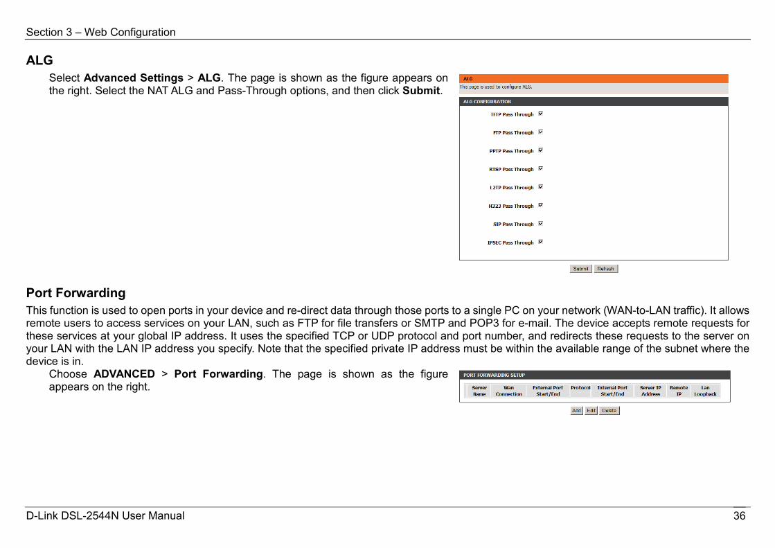
ALG Select Advanced Settings > ALG. The page is shown as the figure appears on the right. Select the NAT ALG and Pass-Through options, and then click Submit.
Port Forwarding This function is used to open ports in your device and re-direct data through those ports to a single PC on your network (WAN-to-LAN traffic). It allows remote users to access services on your LAN, such as FTP for file transfers or SMTP and POP3 for e-mail. The device accepts remote requests for these services at your global IP address. It uses the specified TCP or UDP protocol and port number, and redirects these requests to the server on your LAN with the LAN IP address you specify. Note that the specified private IP address must be within the available range of the subnet where the device is in.
Choose ADVANCED > Port Forwarding. The page is shown as the figure appears on the right.
D-Link DSL-2544N User Manual 36
Section 3 – Web Configuration
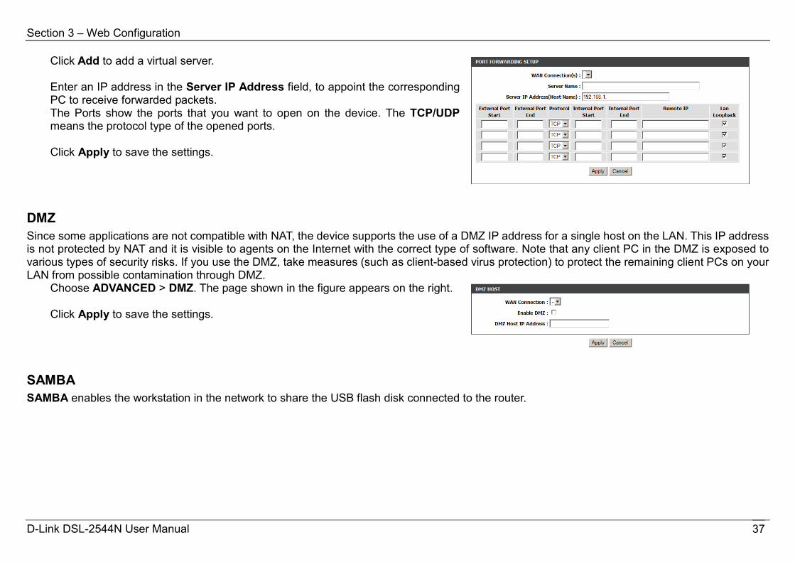
Click Add to add a virtual server. Enter an IP address in the Server IP Address field, to appoint the corresponding PC to receive forwarded packets. The Ports show the ports that you want to open on the device. The TCP/UDP means the protocol type of the opened ports. Click Apply to save the settings.
DMZ Since some applications are not compatible with NAT, the device supports the use of a DMZ IP address for a single host on the LAN. This IP address is not protected by NAT and it is visible to agents on the Internet with the correct type of software. Note that any client PC in the DMZ is exposed to various types of security risks. If you use the DMZ, take measures (such as client-based virus protection) to protect the remaining client PCs on your LAN from possible contamination through DMZ.
Choose ADVANCED > DMZ. The page shown in the figure appears on the right. Click Apply to save the settings.
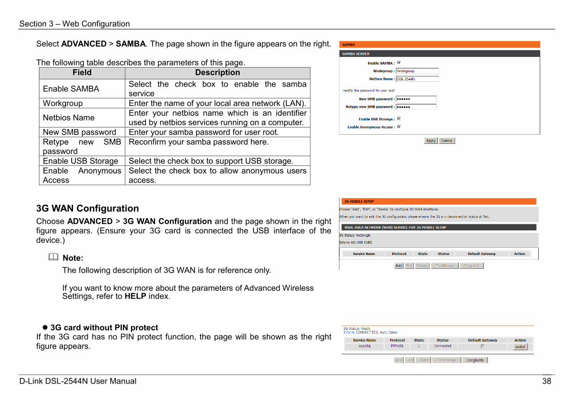
SAMBA SAMBA enables the workstation in the network to share the USB flash disk connected to the router.
D-Link DSL-2544N User Manual 37
Section 3 – Web Configuration
Select ADVANCED > SAMBA. The page shown in the figure appears on the right. The following table describes the parameters of this page.
Field Description
Enable SAMBA Select the check box to enable the samba service
Workgroup Enter the name of your local area network (LAN).
Netbios Name Enter your netbios name which is an identifier used by netbios services running on a computer.
New SMB password Enter your samba password for user root. Retype new SMB password
Reconfirm your samba password here.
Enable USB Storage Select the check box to support USB storage. Enable Anonymous Access
Select the check box to allow anonymous users access.
3G WAN Configuration Choose ADVANCED > 3G WAN Configuration and the page shown in the right figure appears. (Ensure your 3G card is connected the USB interface of the device.)
Note: The following description of 3G WAN is for reference only.
If you want to know more about the parameters of Advanced Wireless Settings, refer to HELP index.
3G card without PIN protect If the 3G card has no PIN protect function, the page will be shown as the right figure appears.
D-Link DSL-2544N User Manual 38
Section 3 – Web Configuration
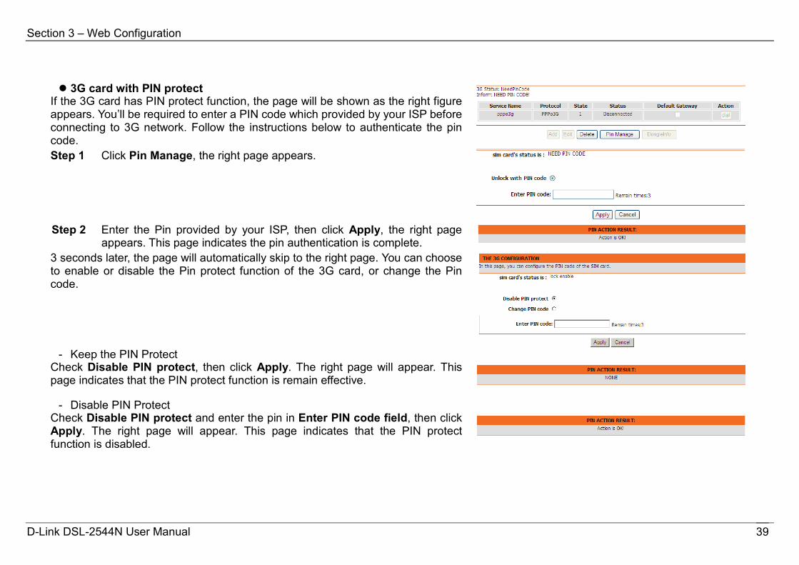
3G card with PIN protect
If the 3G card has PIN protect function, the page will be shown as the right figure appears. You’ll be required to enter a PIN code which provided by your ISP before connecting to 3G network. Follow the instructions below to authenticate the pin code.
Step 1 Click Pin Manage, the right page appears.
Step 2 Enter the Pin provided by your ISP, then click Apply, the right page
appears. This page indicates the pin authentication is complete.
3 seconds later, the page will automatically skip to the right page. You can choose to enable or disable the Pin protect function of the 3G card, or change the Pin code.
- Keep the PIN Protect
Check Disable PIN protect, then click Apply. The right page will appear. This page indicates that the PIN protect function is remain effective.
- Disable PIN Protect Check Disable PIN protect and enter the pin in Enter PIN code field, then click Apply. The right page will appear. This page indicates that the PIN protect function is disabled.
D-Link DSL-2544N User Manual 39

Section 3 – Web Configuration
- Change PIN Code Check Change PIN code, and the right page appears. Enter the required PIN code and click Apply.
If the operation is successful, the right page will appear.
Note: If you want to go back to the main page of 3G configuration, click 3G Configuration listed in the menu of left pane.
Edit an Existing 3G Configuration
If you want to edit an existing 3G configuration, click Edit in the main page of 3G configuration.
Note: If you want to edit the 3G configuration, please ensure the 3G is in disconnection status at first.
D-Link DSL-2544N User Manual 40

Section 3 – Web Configuration
Click Edit, and the right page appears. The following table describes the parameters of this page.
Field Description
Dial_Number The number to be dialed to connect to 3G network. It’s recommended to keep it as default.
Net Type Choose the 3G network access type. Backup Delay Time
The response time for 3G connection dial-up after DSL or Ethernet uplink is disconnected.
Recovery Delay Time
The time interval to re-dial.
Initialize Delay Time
The time for 3G card to initialize.
Mode Switch Delay Time
The time for mode switch.
After setting, click Apply to make the settings take effect. Click AutoSet to keep the settings as default.
Parental Control Choose ADVANCED > Parental Control. The Parent Control page is shown as the figure appears on the right. This page provides two useful tools for restricting the Internet access. Block Website allows you to quickly create a list of all websites that you wish to stop users from accessing. MAC Filter allows you to control when clients or PCs connected to the device are allowed to access the Internet.
D-Link DSL-2544N User Manual 41

Section 3 – Web Configuration
Block Website In the Parent Control page, click Block Website. The page is shown as the figure appears on the right.
Click Add. The page shown in the following page appears. Enter the website to be blocked in the URL field. Select the corresponding time and days when the entered website is blocked. Click Apply to add the website to the BLOCK WEBSITE table. The page is shown as the figure appears on the right.
MAC Filter In the Parent Control page, click MAC Filter. The page is shown as the figure appears on the right.
D-Link DSL-2544N User Manual 42

Section 3 – Web Configuration
Click Add. The page shown in the following page appears. Enter the use name and MAC address and select the corresponding time and days. Click Apply to add the MAC address to the BLOCK MAC ADDRESS table.
Filtering Options Choose ADVANCED > Filtering Options. The Filtering Options page is shown as the figure appears on the right.
D-Link DSL-2544N User Manual 43
Section 3 – Web Configuration
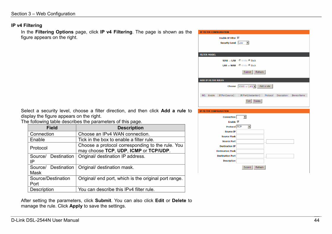
IP v4 Filtering In the Filtering Options page, click IP v4 Filtering. The page is shown as the figure appears on the right.
Select a security level, choose a filter direction, and then click Add a rule to display the figure appears on the right. The following table describes the parameters of this page.
Field Description Connection Choose an IPv4 WAN connection. Enable Tick in the box to enable a filter rule.
Protocol Choose a protocol corresponding to the rule. You may choose TCP, UDP, ICMP or TCP/UDP.
Source/ Destination IP
Original/ destination IP address.
Source/ Destination Mask
Original/ destination mask.
Source/Destination Port
Original/ end port, which is the original port range.
Description You can describe this IPv4 filter rule. After setting the parameters, click Submit. You can also click Edit or Delete to manage the rule. Click Apply to save the settings.
D-Link DSL-2544N User Manual 44

Section 3 – Web Configuration
Note: The settings only apply when the firewall is enabled.
IP v6 Filtering The configuration on IP v6 Filtering is similar to that on IP v4 Filtering. For the parameters description, please refer to IP v4 Filtering.
QoS Choose ADVANCED > QoS. The QoS Configuration page shown in the figure appears on the right. The following table describes the parameters of this page.
Field Description QOS Choose the box to enable the QOS. Direction Choose Upstream queue or Downstream queue. Queue Enable Tick in the box to enable queue. Bandwidth Total bandwidth for upstream flow Discipline Discipline type of QOS
WRR weight When Discipline was chosen to WRR, you can config WRR
Enable DSCP Mark
You may tick in the box to permit DSCP Mark.
Enable 802.1P Mark
You may tick in the box to permit 802.1P Mark.
After setting the parameters, click Save to save the QOS configuration. In this page, click Add Rule. The page shown in the figure appears on the right. You can configure QoS queue rule.
D-Link DSL-2544N User Manual 45
Section 3 – Web Configuration
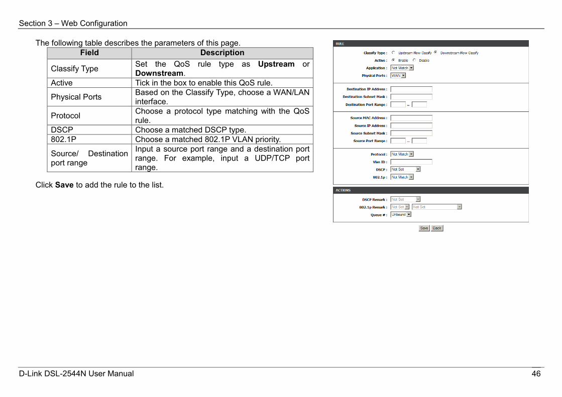
The following table describes the parameters of this page. Field Description
Classify Type Set the QoS rule type as Upstream or Downstream.
Active Tick in the box to enable this QoS rule.
Physical Ports Based on the Classify Type, choose a WAN/LAN interface.
Protocol Choose a protocol type matching with the QoS rule.
DSCP Choose a matched DSCP type. 802.1P Choose a matched 802.1P VLAN priority.
Source/ Destination port range
Input a source port range and a destination port range. For example, input a UDP/TCP port range.
Click Save to add the rule to the list.
D-Link DSL-2544N User Manual 46
Section 3 – Web Configuration
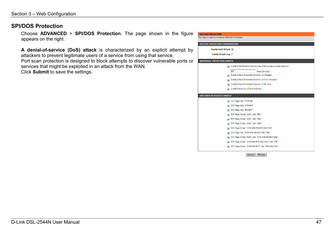
SPI/DOS Protection Choose ADVANCED > SPI/DOS Protection. The page shown in the figure appears on the right. A denial-of-service (DoS) attack is characterized by an explicit attempt by attackers to prevent legitimate users of a service from using that service. Port scan protection is designed to block attempts to discover vulnerable ports or services that might be exploited in an attack from the WAN. Click Submit to save the settings.
D-Link DSL-2544N User Manual 47

Section 3 – Web Configuration
DNS Domain name system (DNS) is an Internet service that translates domain names into IP addresses. Because domain names are alphabetic, they are easier to remember. The Internet, however, is actually based on IP addresses. Each time you use a domain name, a DNS service must translate the name into the corresponding IP address. For example, the domain name www.example.com might be translated to 198.105.232.4. The DNS system is, in fact, its own network. If one DNS server does not know how to translate a particular domain name, it asks another one, and so on, until the correct IP address is returned. Choose ADVANCED > DNS. The page is shown as the figure appears on the right. If you are using the device for DHCP service on the LAN or using DNS servers on the ISP network, select IPv4 static DNS and enter these IP addresses in the available entry fields for the preferred DNS server and the alternate DNS server. Click Apply to save the settings.
D-Link DSL-2544N User Manual 48
Section 3 – Web Configuration
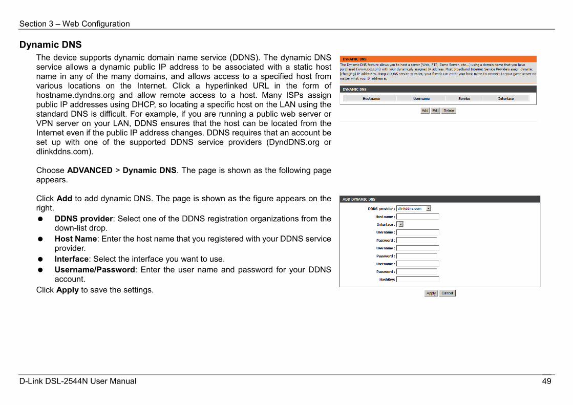
Dynamic DNS The device supports dynamic domain name service (DDNS). The dynamic DNS service allows a dynamic public IP address to be associated with a static host name in any of the many domains, and allows access to a specified host from various locations on the Internet. Click a hyperlinked URL in the form of hostname.dyndns.org and allow remote access to a host. Many ISPs assign public IP addresses using DHCP, so locating a specific host on the LAN using the standard DNS is difficult. For example, if you are running a public web server or VPN server on your LAN, DDNS ensures that the host can be located from the Internet even if the public IP address changes. DDNS requires that an account be set up with one of the supported DDNS service providers (DyndDNS.org or dlinkddns.com). Choose ADVANCED > Dynamic DNS. The page is shown as the following page appears.
Click Add to add dynamic DNS. The page is shown as the figure appears on the right. DDNS provider: Select one of the DDNS registration organizations from the
down-list drop. Host Name: Enter the host name that you registered with your DDNS service
provider. Interface: Select the interface you want to use. Username/Password: Enter the user name and password for your DDNS
account. Click Apply to save the settings.
D-Link DSL-2544N User Manual 49
Section 3 – Web Configuration
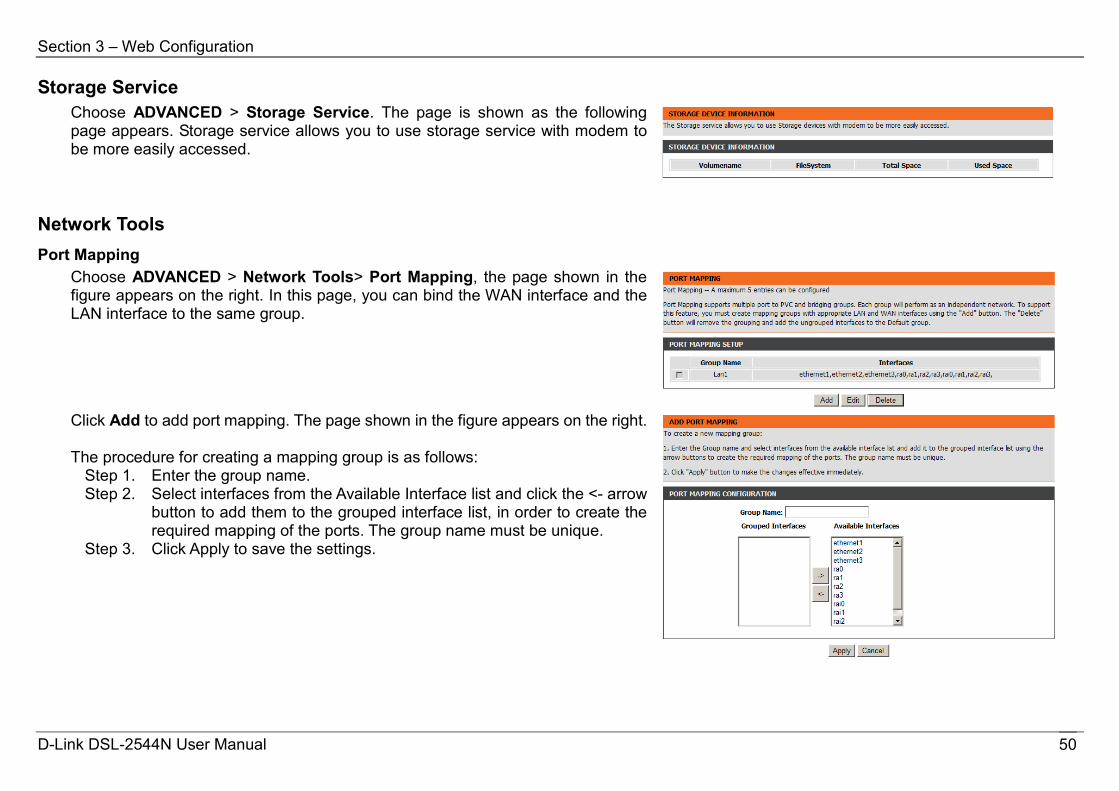
Storage Service Choose ADVANCED > Storage Service. The page is shown as the following page appears. Storage service allows you to use storage service with modem to be more easily accessed.
Network Tools Port Mapping
Choose ADVANCED > Network Tools> Port Mapping, the page shown in the figure appears on the right. In this page, you can bind the WAN interface and the LAN interface to the same group.
Click Add to add port mapping. The page shown in the figure appears on the right. The procedure for creating a mapping group is as follows:
Step 1. Enter the group name. Step 2. Select interfaces from the Available Interface list and click the <- arrow
button to add them to the grouped interface list, in order to create the required mapping of the ports. The group name must be unique.
Step 3. Click Apply to save the settings.
D-Link DSL-2544N User Manual 50
Section 3 – Web Configuration
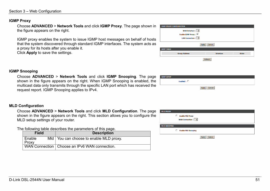
IGMP Proxy Choose ADVANCED > Network Tools and click IGMP Proxy. The page shown in the figure appears on the right. IGMP proxy enables the system to issue IGMP host messages on behalf of hosts that the system discovered through standard IGMP interfaces. The system acts as a proxy for its hosts after you enable it. Click Apply to save the settings.
IGMP Snooping Choose ADVANCED > Network Tools and click IGMP Snooping. The page shown in the figure appears on the right. When IGMP Snooping is enabled, the multicast data only transmits through the specific LAN port which has received the request report. IGMP Snooping applies to IPv4.
MLD Configuration Choose ADVANCED > Network Tools and click MLD Configuration. The page shown in the figure appears on the right. This section allows you to configure the MLD setup settings of your router. The following table describes the parameters of this page.
Field Description Enable Mld Proxy
You can choose to enable MLD proxy.
WAN Connection Choose an IPv6 WAN connection.
D-Link DSL-2544N User Manual 51
Section 3 – Web Configuration
Enable MLD Snooping
Multicast Listener Discovery Snooping (MLD Snooping) is an IPv6 multicast constraining mechanism that runs on Layer 2 devices to manage and control IPv6 multicast groups. By analyzing received MLD messages, a Layer 2 device running MLD Snooping establishes mappings between ports and multicast MAC addresses and forwards IPv6 multicast data based on these mappings.
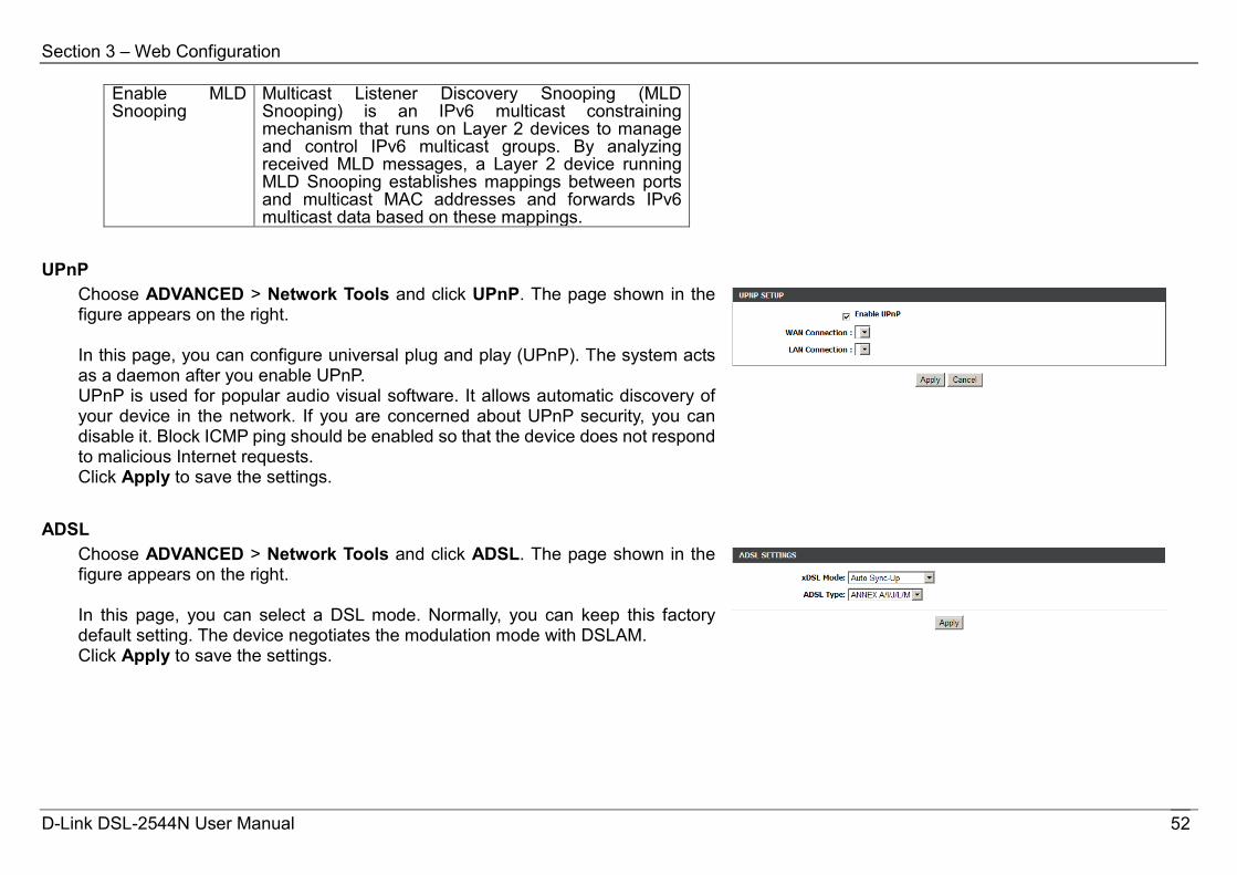
UPnP Choose ADVANCED > Network Tools and click UPnP. The page shown in the figure appears on the right. In this page, you can configure universal plug and play (UPnP). The system acts as a daemon after you enable UPnP. UPnP is used for popular audio visual software. It allows automatic discovery of your device in the network. If you are concerned about UPnP security, you can disable it. Block ICMP ping should be enabled so that the device does not respond to malicious Internet requests. Click Apply to save the settings.
ADSL Choose ADVANCED > Network Tools and click ADSL. The page shown in the figure appears on the right. In this page, you can select a DSL mode. Normally, you can keep this factory default setting. The device negotiates the modulation mode with DSLAM. Click Apply to save the settings.
D-Link DSL-2544N User Manual 52
Section 3 – Web Configuration
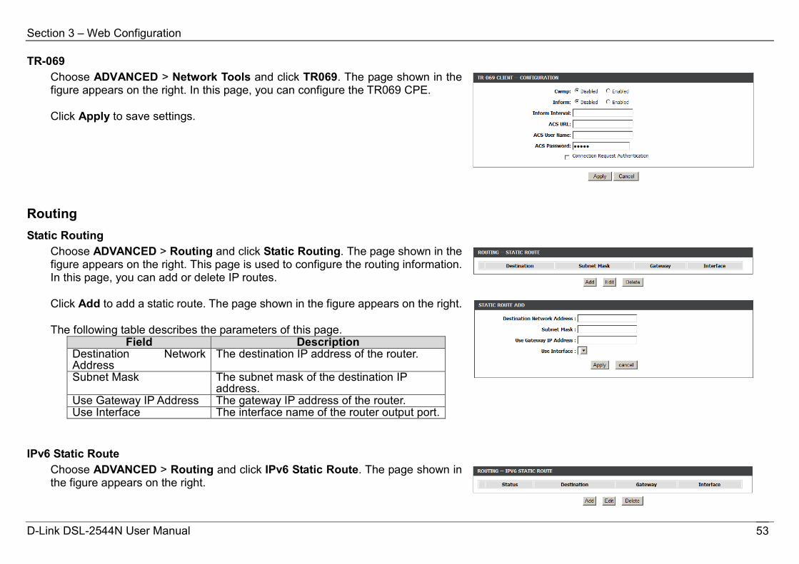
TR-069 Choose ADVANCED > Network Tools and click TR069. The page shown in the figure appears on the right. In this page, you can configure the TR069 CPE. Click Apply to save settings.
Routing Static Routing
Choose ADVANCED > Routing and click Static Routing. The page shown in the figure appears on the right. This page is used to configure the routing information. In this page, you can add or delete IP routes.
Click Add to add a static route. The page shown in the figure appears on the right. The following table describes the parameters of this page.
Field Description Destination Network Address
The destination IP address of the router.
Subnet Mask The subnet mask of the destination IP address.
Use Gateway IP Address The gateway IP address of the router. Use Interface The interface name of the router output port.
IPv6 Static Route Choose ADVANCED > Routing and click IPv6 Static Route. The page shown in the figure appears on the right.
D-Link DSL-2544N User Manual 53
Section 3 – Web Configuration
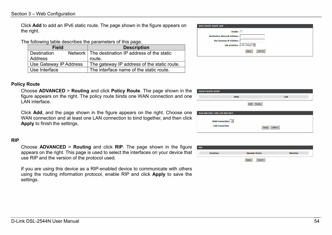
Click Add to add an IPv6 static route. The page shown in the figure appears on the right. The following table describes the parameters of this page.
Field Description Destination Network Address
The destination IP address of the static route.
Use Gateway IP Address The gateway IP address of the static route. Use Interface The interface name of the static route.
Policy Route Choose ADVANCED > Routing and click Policy Route. The page shown in the figure appears on the right. The policy route binds one WAN connection and one LAN interface.
Click Add, and the page shown in the figure appears on the right. Choose one WAN connection and at least one LAN connection to bind together, and then click Apply to finish the settings.
RIP Choose ADVANCED > Routing and click RIP. The page shown in the figure appears on the right. This page is used to select the interfaces on your device that use RIP and the version of the protocol used. If you are using this device as a RIP-enabled device to communicate with others using the routing information protocol, enable RIP and click Apply to save the settings.
D-Link DSL-2544N User Manual 54
Section 3 – Web Configuration
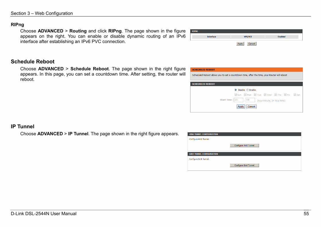
RIPng Choose ADVANCED > Routing and click RIPng. The page shown in the figure appears on the right. You can enable or disable dynamic routing of an IPv6 interface after establishing an IPv6 PVC connection.
Schedule Reboot Choose ADVANCED > Schedule Reboot. The page shown in the right figure appears. In this page, you can set a countdown time. After setting, the router will reboot.
IP Tunnel Choose ADVANCED > IP Tunnel. The page shown in the right figure appears.
D-Link DSL-2544N User Manual 55
Section 3 – Web Configuration
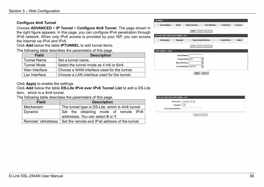
Configure 4in6 Tunnel Choose ADVANCED > IP Tunnel > Configure 4in6 Tunnel. The page shown in the right figure appears. In this page, you can configure IPv4 penetration through IPv6 network. When only IPv6 access is provided by your ISP, you can access the Internet via IPv4 and IPv6. Click Add below the table IPTUNNEL to add tunnel items. The following table describes the parameters of this page.
Field Description Tunnel Name Set a tunnel name. Tunnel Mode Select the tunnel mode as 4 in6 or 6in4. Wan Interface Choose a WAN interface used for the tunnel. Lan Interface Choose a LAN interface used for the tunnel.
Click Apply to enable the settings. Click Add below the table DS-Lite IPv4 over IPv6 Tunnel List to add a DS-Lite item, which is a 4in6 tunnel.
The following table describes the parameters of this page. Field Description
Mechanism The tunnel type is DS-Lite, which is 4in6 tunnel. Dynamic Set the obtaining mode of remote IPv6
addresses. You can select 0 or 1. RemoteI v6Address Set the remote end IPv6 address of the tunnel.
D-Link DSL-2544N User Manual 56

Section 3 – Web Configuration
Configure 6in4 Tunnel Choose ADVANCED > IP Tunnel > Configure 6in4 Tunnel. The page shown in the right figure appears. In this page, you can configure IPv6 penetration through IPv4 network. When only IPv4 access is provided by your ISP, you can access the Internet via IPv4 and IPv6. Click Add below the table IPTUNNEL to add tunnel items. The following table describes the parameters of this page.
Field Description Tunnel Name Set a tunnel name. Tunnel Mode Select the tunnel mode as 4 in6 or 6in4. Wan Interface Choose a WAN interface used for the tunnel. Lan Interface Choose a LAN interface used for the tunnel.
Click Apply to enable the settings. Click Add below the table IPv6 Rapid Deployment to add a 6RD item, which is a 6in4 tunnel.
The following table describes the parameters of this page. Field Description
Mechanism The tunnel type is 6RD, which is a 6in4 tunnel.
Dynamic Set the obtaining mode of Border Relay Address. You may choose 0 or 1.
IPv4MaskLen Set the subnet mask digits of the IPv4 address of the local WAN interface.
Prefix Set the IPv6 prefix of the 6RD tunnel. BorderRelayAddress
Set the Border Relay IPv4 address at the remote end.
Click Apply to enable the settings.
D-Link DSL-2544N User Manual 57

Section 3 – Web Configuration
Logout Choose ADVANCED > Logout. The page is shown as the figure appears on the right. In this page, you can log out of the configuration page.
Management System
Choose MANAGEMENT > System Management. The System page is shown as the figure appears on the right. In this page, you can reboot device, back up the current settings to a file, update and restore the settings from the file saved previously, and restore the factory default settings. The buttons in this page are described as follows: Reboot: Reboot the device. Backup Setting: Save the settings to the local hard drive. Select a location
on your computer to back up the file. You can name the configuration file. Update setting: Click Browse to select the configuration file of device and
click Update Setting to restore the device configuration. Restore Default Setting: Reset the device to default settings. Notice: Do not turn off your device or press the Reset button while an operation in this page is in progress.
D-Link DSL-2544N User Manual 58
Section 3 – Web Configuration
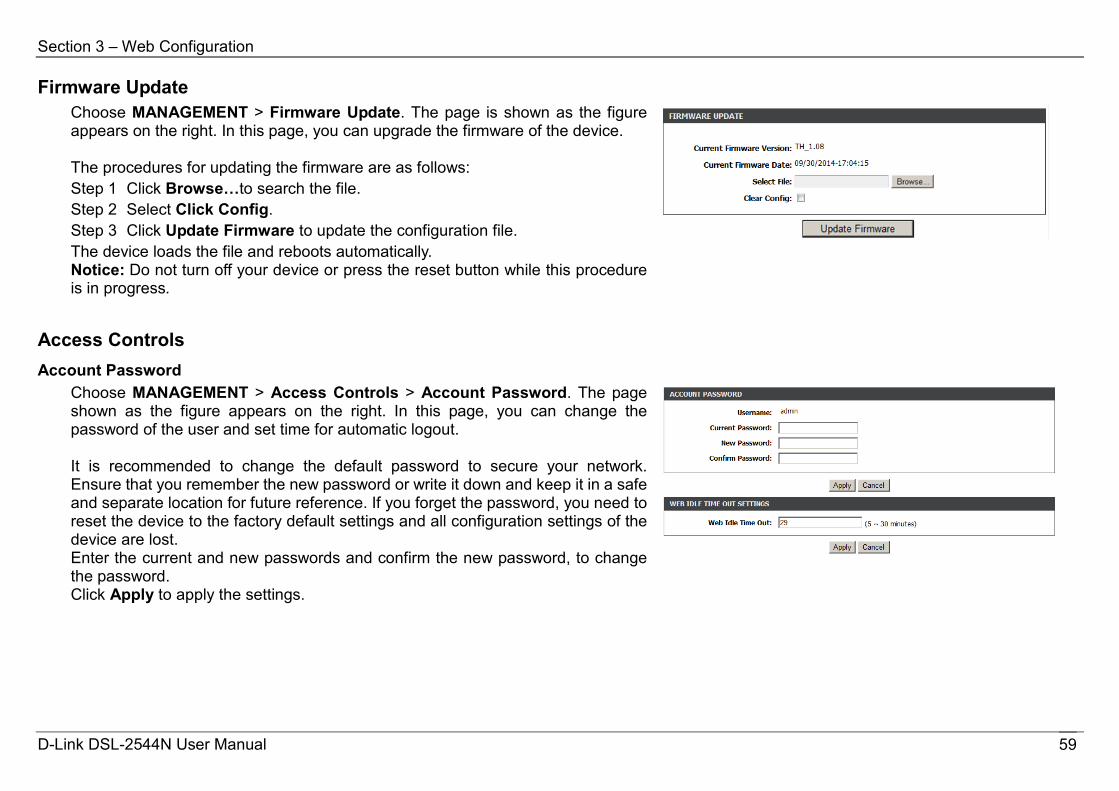
Firmware Update Choose MANAGEMENT > Firmware Update. The page is shown as the figure appears on the right. In this page, you can upgrade the firmware of the device. The procedures for updating the firmware are as follows: Step 1 Click Browse…to search the file. Step 2 Select Click Config. Step 3 Click Update Firmware to update the configuration file. The device loads the file and reboots automatically. Notice: Do not turn off your device or press the reset button while this procedure is in progress.
Access Controls Account Password
Choose MANAGEMENT > Access Controls > Account Password. The page shown as the figure appears on the right. In this page, you can change the password of the user and set time for automatic logout. It is recommended to change the default password to secure your network. Ensure that you remember the new password or write it down and keep it in a safe and separate location for future reference. If you forget the password, you need to reset the device to the factory default settings and all configuration settings of the device are lost. Enter the current and new passwords and confirm the new password, to change the password. Click Apply to apply the settings.
D-Link DSL-2544N User Manual 59

Section 3 – Web Configuration
LACL Choose MANAGEMENT > Access Controls > LACL. The page shown as the figure appears on the right. This page allows you to enable or disable LAN management services. For example, if the Telnet service is enabled on port 23, the remote host can access the router by Telnet through port 23. Click Submit to apply the settings. Note: If you disable HTTP service, you cannot access the configuration page of the device any more.
Remote Access Control Choose MANAGEMENT > Access Controls > Remote Access Control. The page shown as the figure appears on the right. This page allows you to enable or disable WAN management services.
D-Link DSL-2544N User Manual 60
Section 3 – Web Configuration
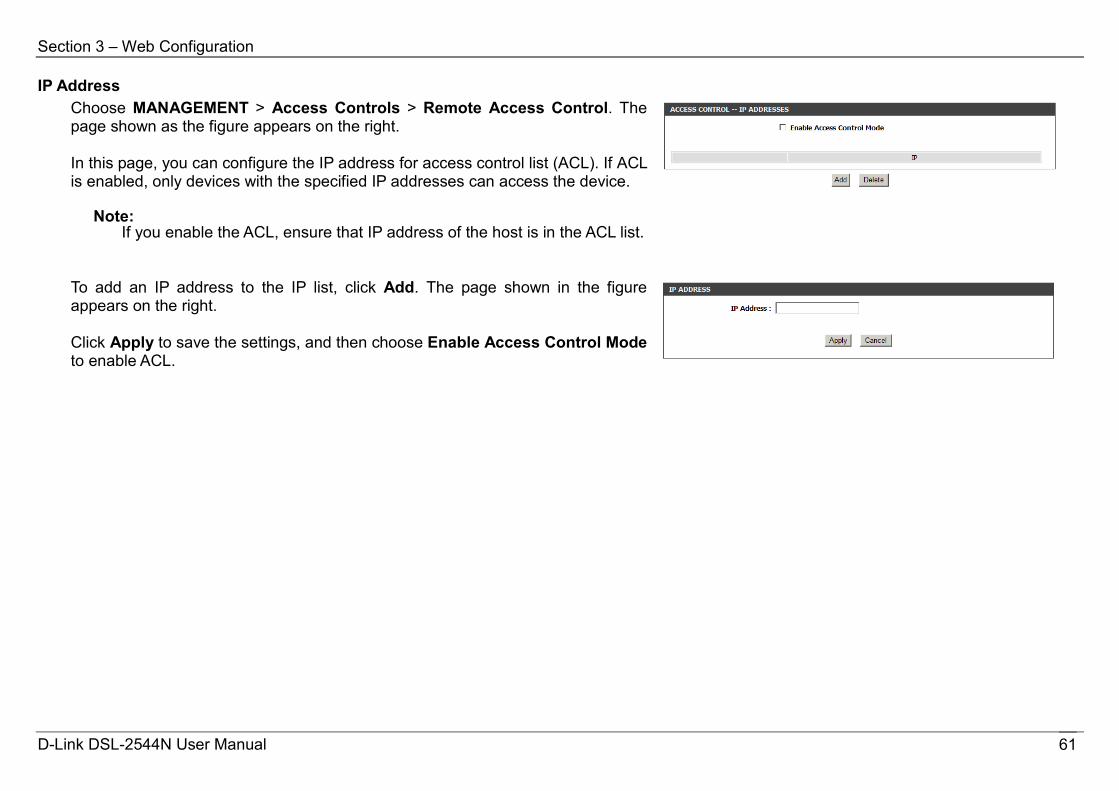
IP Address Choose MANAGEMENT > Access Controls > Remote Access Control. The page shown as the figure appears on the right. In this page, you can configure the IP address for access control list (ACL). If ACL is enabled, only devices with the specified IP addresses can access the device.
Note: If you enable the ACL, ensure that IP address of the host is in the ACL list.
To add an IP address to the IP list, click Add. The page shown in the figure appears on the right. Click Apply to save the settings, and then choose Enable Access Control Mode to enable ACL.
D-Link DSL-2544N User Manual 61
Section 3 – Web Configuration
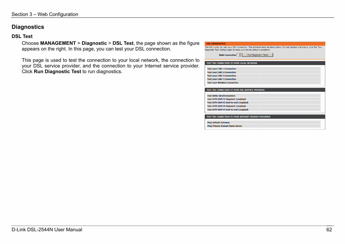
Diagnostics DSL Test
Choose MANAGEMENT > Diagnostic > DSL Test, the page shown as the figure appears on the right. In this page, you can test your DSL connection. This page is used to test the connection to your local network, the connection to your DSL service provider, and the connection to your Internet service provider. Click Run Diagnostic Test to run diagnostics.
D-Link DSL-2544N User Manual 62
Section 3 – Web Configuration
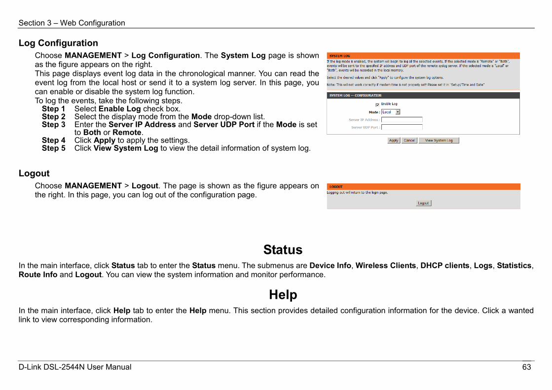
Log Configuration Choose MANAGEMENT > Log Configuration. The System Log page is shown as the figure appears on the right. This page displays event log data in the chronological manner. You can read the event log from the local host or send it to a system log server. In this page, you can enable or disable the system log function. To log the events, take the following steps.
Step 1 Select Enable Log check box. Step 2 Select the display mode from the Mode drop-down list. Step 3 Enter the Server IP Address and Server UDP Port if the Mode is set
to Both or Remote. Step 4 Click Apply to apply the settings. Step 5 Click View System Log to view the detail information of system log.
Logout Choose MANAGEMENT > Logout. The page is shown as the figure appears on the right. In this page, you can log out of the configuration page.
Status In the main interface, click Status tab to enter the Status menu. The submenus are Device Info, Wireless Clients, DHCP clients, Logs, Statistics, Route Info and Logout. You can view the system information and monitor performance.
Help In the main interface, click Help tab to enter the Help menu. This section provides detailed configuration information for the device. Click a wanted link to view corresponding information.
D-Link DSL-2544N User Manual 63
Section 4 - Troubleshooting
Troubleshooting This chapter provides solutions to problems that might occur during the installation and operation of the DSL-2544N. Read the following descriptions if you are having problems.
1. How do I configure my DSL-2544N Router without the CD-ROM?
Step 1 Connect your PC to the Router using an Ethernet cable. Step 2 Open a web browser and enter the address http://192.168.1.1 Step 3 The default username is ‘admin’ and the default password is ‘admin’. Step 4 If you have changed the password and cannot remember it, you will need to reset the Router to the factory default setting (see question 2),
which will set the password back to ‘admin’. Note: Please refer to the next section “Networking Basics” to check your PC’s IP configuration if you can’t see the login windows.
2. How do I reset my Router to the factory default settings?
Step 1 Ensure the Router is powered on. Step 2 Press and hold the reset button on the back of the device for approximately 15 seconds. Step 3 This process should take around 1 to 2 minutes.
Note: Resetting the Router to the factory default settings will erase the current configuration settings. To reconfigure your settings, login to the
Router as outlined in question 1, and then run the Quick Setup wizard. 3. What can I do if my Router is not working correctly?
There are a few quick steps you can take to try and resolve any issues: Step 1 Follow the directions in Question 2 to reset the Router. Step 2 Check that all the cables are firmly connected at both ends. Step 3 Check the LEDs on the front of the Router. The Power indicator should be on, and the DSL and LAN indicators should be on as well. Step 4 Please ensure that the settings in the Web-based configuration manager, e.g. ISP username and password, are the same as the settings
D-Link DSL-2544N User Manual 64
Section 4 – Troubleshooting
that have been provided by your ISP. 4. Why can’t I get an Internet connection?
For ADSL ISP users, please contact your ISP to make sure the service has been enabled/connected by your ISP and that your ISP username and password are correct.
5. What can I do if my Router can’t be detected by running the installation CD?
Step 1 Ensure the Router is powered on. Step 2 Check that all the cables are firmly connected at both ends and all LEDs are working correctly. Step 3 Ensure only one network interface card on your PC is activated. Step 4 Click on Start > Control Panel > Security Center to disable the firewall. Note: There is a potential security issue if the firewall is disabled on your PC. Please remember to turn it back on once you have finished
the whole installation procedure. This will enable you to surf the Internet without any problems.
D-Link DSL-2544N User Manual 65

Appendix A – Networking Basics
Networking Basics Check Your IP Address
After you install your new D-Link adapter, by default, the TCP/IP settings should be set to obtain an IP address from a DHCP server (i.e. wireless router) automatically. To verify your IP address, please follow the steps below.
Click on Start > Run. In the run box type cmd and click on the OK button.
At the prompt, type ipconfig and press Enter.
This will display the IP address, subnet mask and the default gateway of your adapter.
If the address is 0.0.0.0, check your adapter installation, security settings and the settings on your router. Some firewall software programs may block a DHCP request on newly installed adapters.
If you are connecting to a wireless network at a hotspot (e.g. hotel, coffee shop, airport), please contact an employee or administrator to verify their wireless network settings.
D-Link DSL-2544N User Manual 66
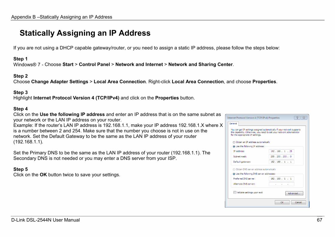
Appendix B –Statically Assigning an IP Address
Statically Assigning an IP Address If you are not using a DHCP capable gateway/router, or you need to assign a static IP address, please follow the steps below:
Step 1 Windows® 7 - Choose Start > Control Panel > Network and Internet > Network and Sharing Center.
Step 2 Choose Change Adapter Settings > Local Area Connection. Right-click Local Area Connection, and choose Properties.
Step 3 Highlight Internet Protocol Version 4 (TCP/IPv4) and click on the Properties button.
Step 4 Click on the Use the following IP address and enter an IP address that is on the same subnet as your network or the LAN IP address on your router. Example: If the router’s LAN IP address is 192.168.1.1, make your IP address 192.168.1.X where X is a number between 2 and 254. Make sure that the number you choose is not in use on the network. Set the Default Gateway to be the same as the LAN IP address of your router (192.168.1.1).
Set the Primary DNS to be the same as the LAN IP address of your router (192.168.1.1). The Secondary DNS is not needed or you may enter a DNS server from your ISP.
Step 5 Click on the OK button twice to save your settings.
D-Link DSL-2544N User Manual 67

Appendix C – Technical Specifications
Technical Specifications ADSL Standards
․ ANSI T1.413 Issue 2 ․ ITU G.992.1 (G.dmt) AnnexA ․ ITU G.992.2 (G.lite) Annex A ․ ITU G.994.1 (G.hs) ․ ITU G.992.5 Annex A
ADSL2 Standards ․ ITU G.992.3 (G.dmt.bis) Annex A ․ ITU G.992.4 (G.lite.bis) Annex A
ADSL2+ Standards ․ ITU G.992.5 (ADSL2+)
Protocols
Data Transfer Rate ․ G.dmt full rate downstream: up to 8 Mbps / upstream: up to 1
Mbps ․ G.lite: ADSL downstream up to 1.5 Mbps / upstream up to 512
Kbps ․ G.dmt.bis full rate downstream: up to 12 Mbps / upstream: up to
12 Mbps ․ ADSL full rate downstream: up to 24 Mbps / upstream: up to 1
Mbps
Media Interface ․ ADSL interface: RJ-11 connector for connection to 24/26 AWG
twisted pair telephone line ․ LAN interface: RJ-45 port for 10/100/1000BASE-T Ethernet
connection ․ IEEE 802.1d Spanning
Tree ․ TCP/UDP ․ ARP ․ RARP ․ ICMP ․ RFC1058 RIP v1 ․ RFC1213 SNMP v1 & v2c ․ RFC1334 PAP ․ RFC1389 RIP v2 ․ RFC1577 Classical IP over
ATM
․ RFC1483/2684 Multiprotocol Encapsulation over ATM Adaptation Layer 5 (AAL5)
․ RFC1661 Point to Point Protocol
․ RFC1994 CHAP ․ RFC2131 DHCP Client /
DHCP Server ․ RFC2364 PPP over ATM ․ RFC2516 PPP over
Ethernet
D-Link DSL-2544N User Manual 68