ds303 tectaverlegeanleitung e 1210 - owa€¦ · 3000 mm 250 625 625 625 625 250 562,5 625 625 625...
TRANSCRIPT

Edition 2010
I N S TA L L AT I O NG U I D E
Guidelines for the planning and installation
of OWAtecta®
Metal Ceiling Systems
Edition 1/2010

2121001
Odenwald Faserplattenwerk GmbH · Dr.-F.-A.-Freundt-Straße 3 · 63916 AmorbachTel.: +49 9373 2 01-0 · Fax: +49 9373 2 01-130 · www.owa.de · E-Mail: [email protected]
Table of contents
Page1. Introduction . . . . . . . . . . . . . . . . . . . . . . . . . . . . . . . . . . . . . . . . . . . . . . . . . . . . . . . . . . . . . . . . . . . . . . . . 3
2. BasicsTechnical guidelines . . . . . . . . . . . . . . . . . . . . . . . . . . . . . . . . . . . . . . . . . . . . . . . . . . . . . . . . . . . . . . . . 4
3. Installation . . . . . . . . . . . . . . . . . . . . . . . . . . . . . . . . . . . . . . . . . . . . . . . . . . . . . . . . . . . . . . . . . . . . . . . . 11
4. OWAtecta® suspension system . . . . . . . . . . . . . . . . . . . . . . . . . . . . . . . . . . . . . . . . . . . . . . . . . . . . . . . . 12
5. Systems
OWAtecta® clip-in systemsS 22 . . . . . . . . . . . . . . . . . . . . . . . . . . . . . . . . . . . . . . . . . . . . . . . . . . . . . . . . . . . . . . . . . . . . . . . . . . 16S 31 and S 32 . . . . . . . . . . . . . . . . . . . . . . . . . . . . . . . . . . . . . . . . . . . . . . . . . . . . . . . . . . . . . . . . . . 18
OWAtecta® lay-in systemsS 33 and S 45 . . . . . . . . . . . . . . . . . . . . . . . . . . . . . . . . . . . . . . . . . . . . . . . . . . . . . . . . . . . . . . . . . . 22
OWAtecta® Corridor systemsS 36 – Success (clip-in profile) . . . . . . . . . . . . . . . . . . . . . . . . . . . . . . . . . . . . . . . . . . . . . . . . . . . . . . . 25S 36 – Swing (G-section) . . . . . . . . . . . . . . . . . . . . . . . . . . . . . . . . . . . . . . . . . . . . . . . . . . . . . . . . . . . 26S 36 – Progress (Z-profile) . . . . . . . . . . . . . . . . . . . . . . . . . . . . . . . . . . . . . . . . . . . . . . . . . . . . . . . . . . 27
OWAtecta® hook-on system S 39 . . . . . . . . . . . . . . . . . . . . . . . . . . . . . . . . . . . . . . . . . . . . . . . . . . . 28
OWAtecta® Linear C-bandraster system S 48 . . . . . . . . . . . . . . . . . . . . . . . . . . . . . . . . . . . . . . . . . 31S 48 Easy . . . . . . . . . . . . . . . . . . . . . . . . . . . . . . . . . . . . . . . . . . . . . . . . . . . . . . . . . . . . . . . . . . . . . . 33S 48 Swing . . . . . . . . . . . . . . . . . . . . . . . . . . . . . . . . . . . . . . . . . . . . . . . . . . . . . . . . . . . . . . . . . . . . . 33
OWAtecta® C-bandraster system S 50 . . . . . . . . . . . . . . . . . . . . . . . . . . . . . . . . . . . . . . . . . . . . . . 35S 50 Easy . . . . . . . . . . . . . . . . . . . . . . . . . . . . . . . . . . . . . . . . . . . . . . . . . . . . . . . . . . . . . . . . . . . . . . 36S 50 Swing . . . . . . . . . . . . . . . . . . . . . . . . . . . . . . . . . . . . . . . . . . . . . . . . . . . . . . . . . . . . . . . . . . . . . 37
OWAtecta® system S 55Impact resistant linear panel system . . . . . . . . . . . . . . . . . . . . . . . . . . . . . . . . . . . . . . . . . . . . . . . . . . . 38
OWAtecta® wall systemS 60 – Magnetic pin board wall absorber . . . . . . . . . . . . . . . . . . . . . . . . . . . . . . . . . . . . . . . . . . . . . . . 40

121001Odenwald Faserplattenwerk GmbH · Dr.-F.-A.-Freundt-Straße 3 · 63916 AmorbachTel.: +49 9373 2 01-0 · Fax: +49 9373 2 01-130 · www.owa.de · E-Mail: [email protected]
This publication provides basic information for the planning and installation of OWAtecta® ceilingsystems.
The information contained within this guide is based onour recommendations and those contained within thecurrent European Standards (EN 13964). Inline withimproving standards and techniques please make sureyou are using the current* issues of both documents.
As a manufacturer and supplier, we offer complete, triedand tested ceiling systems. OWA ceiling systems can beused to provide a variety of performances as well as aesthetic functions.
In all cases the correct installation of the ceiling is essen-tial to ensure that the ceiling can fulfil any such require-ments.
Where the OWA ceiling is to provide any level ofperformance it must be installed in accordancewith the relevant test report, assessment or thoserecommendations provided by OWA. Failure to use the specified components or complywith the installation recommendations will invali-date any test report, assessment or warranty.
*See back page for publication date
1. Introduction
3
OWAtecta®
Installation Guide
4121001
Odenwald Faserplattenwerk GmbH · Dr.-F.-A.-Freundt-Straße 3 · 63916 AmorbachTel.: +49 9373 2 01-0 · Fax: +49 9373 2 01-130 · www.owa.de · E-Mail: [email protected]
Basic PlanningAn OWA ceiling is installed using dry construction me-thods and is generally for interior use only. The basicprinciples of dry construction should be applied wheninstalling the ceilings. Where additional materials such astimber or gypsum are used, the guidelines on workingwith those products should also be observed.
Site conditionsBefore installing an OWA ceiling the room/site conditionsshould be assessed. The area should be weather tight(windows and doors in place) and have a stable, dry envi-ronment. The ceiling should only be installed after thewet trades, such as plaster- and screed-work have beencompleted and the environment is dry and stable.
Reference values for site environmentsGenerally the relative humidity should be < 70 % RH(reference temperature 25 °C), but it is recommended thatinstallation should take place at temperature and humiditylevels similar to those that will prevail during subsequentoccupation.
Standards for suspended ceilingsEN 13964 Suspended Ceilings – requirements and testmethods, has now been accepted in most European coun-tries as the prevailing standard and provides informationfor manufacturers,specifiers and users of suspendedceilings. Covering complete ceiling "Kits" and individualcomponents it also provides test methods, methods ofassessments and provisions for the evaluation for con-formity of the products to the requirements shown in thestandard.
QualityDimensions, material characteristics and colour arecovered by EN 13964
2. Basics
Technical guidelines
ColourAllowable tolerances in shade of colour OWA whiteThe difference in Δ E value within one production batchmay not exceed a value of 1.0. Where the materials usedare from more than one production batch the tolerancemay be greater than Δ E = 1.0. Greater variation may beexpected when installing materials purchased as individualorders over extended periods of time.
Fire OWAtecta® panels as building materialNote: The word "panel" is used as a generic term withinthis document to describe tiles, planks and linear panels.Where more clarity is required the definitions shown inEN 13964 will be used.
Reaction to Fire Classifications – EN 13501-1When tested to EN 13501-1, building materials are divided into a classification ranging from A1 to F with A1providing the best performance. As well as measuring amaterials contribution to fire this standard has intro-duced criteria measuring smoke generation (s) and production of burning droplets (d).
In most countries of the EC you will find tables that translatethe previous class according to local standard to the rele-vant EC class. For countries outside the EC, please checkyour local regulations or call your nearest OWA office.
The additional designations are:Smokes1, s2, s3 s1 = little or no smoke generation S2 = medium smoke generation S3 = heavy smoke generationBurning dropletsd0, d1, d2d0 = no droplets within 600 secondsd1 = droplet form within 600 seconds but do not burn for more
than 10 secondsd2 = Not as d0 or d1
Country Test standard ClassificationStandards: See table in installation guide for mineral wool tiles!
OWAtecta® ceiling systems fall into Class A1. Additionalelements such as non-woven backings, insulation pads,foam strips, etc. may affect the material fire classification.
OWAtecta® Ceilings – Structural componentsEN 13501-2 considers a "building component" to be the
OWAtecta®
Installation Guide

zu schützender Raum
Brandraum
zu schützender Raum
Brandraum
121001Odenwald Faserplattenwerk GmbH · Dr.-F.-A.-Freundt-Straße 3 · 63916 AmorbachTel.: +49 9373 2 01-0 · Fax: +49 9373 2 01-130 · www.owa.de · E-Mail: [email protected]
2. Basics
Technical guidelines
Fire Resistance with OWAtecta®
When used in conjunction with OWAcoustic® panels fireresistance can be achieved using a number ofOWAtecta® ceiling systems. Independent fire resistantOWAtecta® ceiling systems are also available.The performances shown in our test reports are onlyvalid when OWAtecta® systems, panels and componentsare used and installed in accordance with the relevanttest report.
SoundOWAtecta® ceiling systems can fulfill a wide range offunctions relating to the control of sound.
Optimising room acousticsIn many rooms, the correct reverberation time T [s] isrequired for good comprehension of speech or apprecia-tion of music. Similarly in noise-intensive productionfacilities or workshops, the greatest possible sound levelreduction is required to make the environment morecomfortable.
Reverberation time regulation Tdesired [s]Noise level reduction Δ L [dB]
The four following standards contain the basics of mea-suring room acoustics. The requirements for specificapplications depend on local or country regulations; wesuggest you ask our local sales offices for guidance.
• EN ISO 354 Measurement of sound absorption in areverberation room
• EN ISO 140 Measurement of sound insulation in buil-dings and of building elements
• EN ISO 3382 Measurement of the reverberation timeof rooms ...
• EN ISO 10848 Laboratory measurement of the flank-ing transmission of airborne and impact sound bet-ween adjoining rooms
Optimising building acousticsOWAtecta® ceiling systems can be used to reduce andcontrol airborne sound generated from the cavity andadjacent rooms especially when combined with additionalinfill elements, such as OWAcoustic mineral wool panels.This combination is even more important when using per-forated metal panels.
In the modified form the ceiling can be used to:• enhance the airborne sound insulation Rw [dB] of solid
and wooden beam soffits
5
OWAtecta®
Installation Guide
Area to be protected
Fire
complete construction of soffit/floor plus suspendedceiling and it is the complete construction that is subjectto test. The total construction should prevent the passageof fire and provide effective insulation for as long aspossible. It is therefore important to use the complete,proven, ceiling system where performance is required.
Standards for the load-bearing building component: Soffit + Suspended Ceiling
Depending on their fire resistance duration, building com-ponents are divided into the following classes:
Classification Resistance to Fire Durationaccording to EN 13501-2 (minutes)REI 30 30REI 60 60REI 90 90REI 120 120REI 180 180
The fire resistance of structures in combination with sus-pended ceilings must be proven by fire tests accordingto European standards. Tests covering many typical con-structions have been successfully carried out with OWAceiling systems.
The OWA fire resistance test results are only valid if com-plete OWA ceiling systems are installed.
Fire resistance from above and belowWe have developed specialist ceiling systems that canbe used to provide fire resistance from above and belowachieving class EI 30 (a <–> b)
Area to be protected
Fire
3000 mm
250 625 625 625 625 250 562,5 625 625 625 562,5
6121001
Odenwald Faserplattenwerk GmbH · Dr.-F.-A.-Freundt-Straße 3 · 63916 AmorbachTel.: +49 9373 2 01-0 · Fax: +49 9373 2 01-130 · www.owa.de · E-Mail: [email protected]
• improve sound insulation Dn,c,w [dB] between twoadjacent rooms with a common plenum
• reduce noises from the plenumAs installation conditions vary from site to site each pro-ject should be assessed on its own merits. Where theacoustic performance of a room is important it is recom-mended that a qualified acoustician be consulted.
If you are looking for additional information on buildingacoustic requirements, we recommend you consulteither ISO, EN or local standards and regulations: Ofcourse you can always contact your OWA sales office forinformation.
Planning before installationAn inspection of the building site to check local condi-tions, site measurement of the rooms and production ofan installation plan are important preliminary work steps.The ceiling layout, arrangement of lighting and similarmatters must be determined with the architect.
Structural physics basics:All planning relevant aspects, such as determining venti-lation cross-sections, air exchange rates, arrangementof vapour barriers, humidity, feasibility of a soffit in thecase of a ventilated ceiling with regard to the formationof any condensation in the building etc, must be de-termined by an expert planner (building physicist) and ifnecessary tested!
Requirements regarding building physics, fire protection,acoustics or other matters, which could arise amongother things from the relevant standards, have not beenconsidered in this installation brochure.
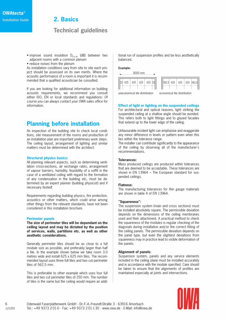
Perimeter panelsThe size of perimeter tiles will be dependant on theceiling layout and may be dictated by the positionof services, walls, partitions etc. as well as otheraesthetic considerations.
Generally perimeter tiles should be as close to a fullmodule size as possible, and preferably larger than halfa tile. In the example shown below we take room 3.0metres wide and install 625 x 625 mm tiles. The recom-mended layout uses three full tiles and two cut perimetertiles of 562,5 mm.
This is preferable to other example which uses four fulltiles and two cut perimeter tiles of 250 mm. The numberof tiles is the same but the ceiling would require an addi-
2. Basics
Technical guidelines
tional run of suspension profiles and be less aestheticallybalanced.
Example:
uneconomical tile distribution economical tile distribution
Effect of light or lighting on the suspended ceilingsFor architectural and optical reasons, light striking thesuspended ceiling at a shallow angle should be avoided.This refers both to light fittings and to glazed facadesthat extend up to the lower edge of the ceiling.
Unfavourable incident light can emphasise and exaggerateany minor difference in levels or pattern even when thislies within the tolerance range.The installer can contribute significantly to the appearanceof the ceiling by observing all of the manufacturer'srecommendations.
Tolerances: Mass produced ceilings are produced within tolerancesthat are deemed to be acceptable. These tolerances areshown in EN 13964 – The European standard for sus-pended ceilings.
Flatness:The manufacturing tolerances for thin gauge materialsare shown in table 4 of EN 13964.
"Squareness":The suspension system (main and cross sections) mustbe installed absolutely square. The permissible deviationdepends on the dimensions of the ceiling membranesused and their attachment. A practical method to checkthe squareness of the modules is regular checking of thediagonals during installation and/or the correct fitting ofthe ceiling panels. The permissible deviation depends onthe panel type, but even the slightest deviations fromsquareness may in practice lead to visible deformation ofthe panels.
Alignment of panels:Suspension system, panels and any service elementsincluded in the ceiling plane must be installed accuratelyand in accordance with the module specified. Care shouldbe taken to ensure that the alignments of profiles aremaintained especially at joints and intersections.
OWAtecta®
Installation Guide

121001Odenwald Faserplattenwerk GmbH · Dr.-F.-A.-Freundt-Straße 3 · 63916 AmorbachTel.: +49 9373 2 01-0 · Fax: +49 9373 2 01-130 · www.owa.de · E-Mail: [email protected]
2. Basics
Technical guidelines
7
OWAtecta®
Installation Guide
Cutting to size of perimeter panels:Normally the ceiling layout will be based on the centreline of the room bisecting, or running along the junctionof a panel. Unless otherwise agreed, whichever providesthe largest perimeter panel is normally used. Ideally theperimeter panel should be at least half the size of thepanel. When cut, installed and pushed over against thetee parallel with wall, at least 10 mm of the panel shouldbe resting on the perimeter trim.
Expansion and movement jointsIn small areas, temperature fluctuations due to solar gainor environmental variations rarely cause problems, how-ever in large areas or those where materials with varyingexpansion coefficients have been used expansion or con-traction may adversely affect the ceiling. In such casesspecial allowances should be made, especially at theperimeters.
Where building expansion and movement joints have beenincluded in the building design, these should be replicatedin the ceiling membrane or suspended ceiling.
Pressure and wind loadsClosed room and buildings with open facades are justtwo examples where wind loading and/or air pressurewithin a room can create additional loads on ceilings.Where such problems can be identified additional meas-ures must be taken to protect the stability and securityof the ceiling and components within the ceiling plane.
Load-bearing capacityAll ceiling systems (suspended ceiling kits) shown in thisguide have been tested for load-bearing capacity inaccordance with EN 13964.
As shown here Table 6 provides classifications of down-ward deflection with Class 1 requiring a maximum L/500deflection of 4 mm. When used in accordance with ourrecommendations OWAconstruct® profiles meet therequirements of Class 1. Where you require performancedata for other standards please contact us.
Class Maximum deflection in mm1 L/500 and no greater than 4 mm2 L/3003 No limit
L is the span between the suspension components or suspension points
Additional LoadsOWAconstruct® systems are designed to support theload created from the suspension system and ceilingpanels. Additional loads such as recessed and surfacemounted light fittings, air outlets, insulation quilt, curtainrails and partitions should be independently suspended.OWA may be able to provide effective methods of sup-porting some additional loads with minimum cost anddisruption.
No altered or adapted profiles (notching, drilling, etc.)should be used under load without prior consultation.
8121001
Odenwald Faserplattenwerk GmbH · Dr.-F.-A.-Freundt-Straße 3 · 63916 AmorbachTel.: +49 9373 2 01-0 · Fax: +49 9373 2 01-130 · www.owa.de · E-Mail: [email protected]
Corrosion protection of profiles,hangers and membrane materialsThe humidity level within a room not only affects themembrane material but may also have an effect on thesuspension system and associated components. Theseare generally manufactured from cold rolled steel andshould have the correct level of corrosion resistance tomatch the proposed installation environment.
Excerpt from EN 13964:The environmental conditions are defined in Table 7.
Table 7 – Classes of exposure
Class Condition
A Building components generally exposed to varying relative humidity up to 70 % and varying temperature up to 25 °C but without corrosive pollutants.
B Building components frequently exposed to varying relative humidity up to 90 % and varying temperature up to 30 °C but without corrosive pollutants.
C Building components exposed to an atmosphere with a level of humidity higher than 90 % and accompanied by a risk of condensation.
D More severe than the above.
In EN 13964 table 8 gives the minimum requirements forcorrosion protection according to the classes of Table 7.
2. Basics
Technical guidelines
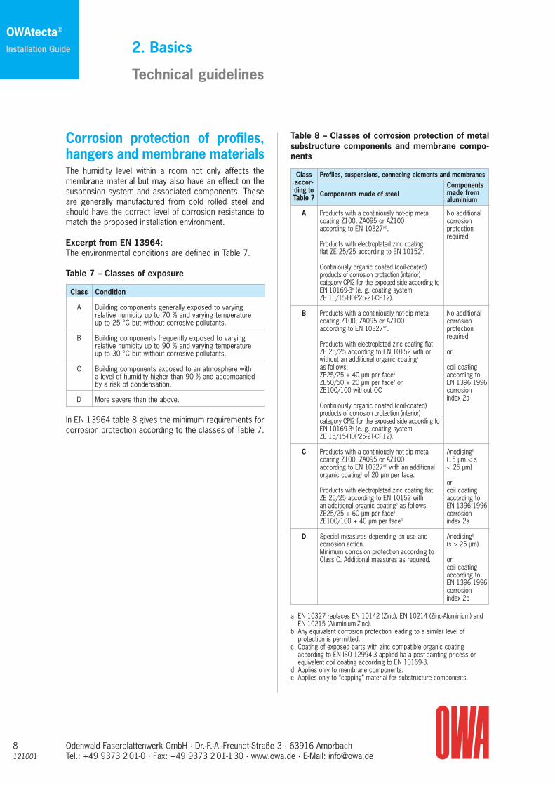
Table 8 – Classes of corrosion protection of metalsubstructure components and membrane compo-nents
Class Profiles, suspensions, connecing elements and membranesaccor- Componentsding to Components made of steel made fromTable 7 aluminium
A Products with a continiously hot-dip metal No additionalcoating Z100, ZA095 or AZ100 corrosion according to EN 10327a,b. protection
required Products with electroplated zinc coating flat ZE 25/25 according to EN 10152b.
Continiously organic coated (coil-coated)products of corrosion protection (interior) category CPI2 for the exposed side according toEN 10169-3e (e. g. coating system ZE 15/15-HDP25-2T-CP12).
B Products with a continiously hot-dip metal No additionalcoating Z100, ZA095 or AZ100 corrosion according to EN 10327a,b. protection
required Products with electroplated zinc coating flatZE 25/25 according to EN 10152 with or orwithout an additional organic coatingc
as follows: coil coatingZE25/25 + 40 μm per faced, according toZE50/50 + 20 μm per faced or EN 1396:1996ZE100/100 without OC corrosion
index 2a Continiously organic coated (coil-coated)products of corrosion protection (interior) category CPI2 for the exposed side according toEN 10169-3e (e. g. coating system ZE 15/15-HDP25-2T-CP12).
C Products with a continiously hot-dip metal Anodisingb
coating Z100, ZA095 or AZ100 (15 μm < saccording to EN 10327a,b with an additional < 25 μm)organic coatingc of 20 μm per face.
orProducts with electroplated zinc coating flat coil coatingZE 25/25 according to EN 10152 with according toan additional organic coatingc as follows: EN 1396:1996ZE25/25 + 60 μm per faced corrosionZE100/100 + 40 μm per faced index 2a
D Special measures depending on use and Anodisingb
corrosion action. (s > 25 μm)Minimum corrosion protection according to Class C. Additional measures as required. or
coil coatingaccording toEN 1396:1996corrosionindex 2b
a EN 10327 replaces EN 10142 (Zinc), EN 10214 (Zinc-Aluminium) andEN 10215 (Aluminium-Zinc).
b Any equivalent corrosion protection leading to a similar level of protection is permitted.
c Coating of exposed parts with zinc compatible organic coating according to EN ISO 12994-3 applied ba a post-painting pricess orequivalent coil coating according to EN 10169-3.
d Applies only to membrane components.e Applies only to “capping” material for substructure components.
OWAtecta®
Installation Guide
121001Odenwald Faserplattenwerk GmbH · Dr.-F.-A.-Freundt-Straße 3 · 63916 AmorbachTel.: +49 9373 2 01-0 · Fax: +49 9373 2 01-130 · www.owa.de · E-Mail: [email protected]
Standard OWAtecta® metal ceiling panels are made ofsheet steel and have a ZE 25/25 electro-galvanised orZE60/ZE60 hot dip galvanized surface. This corresponds to either corrosion protection class Aor B of Table 8.
OWAtecta® subconstruction components have a 7–10 umzinc coating on all sides and therefore meet the require-ments of both class A and Class B of the table 8. It isimportant to ensure that the corrosion resistant protectionis not damaged before or during installation or later whenin general use. Where components are cut or damagedthey must be treated to ensure the required level ofresistance is not compromised.
Contact corrosion:Corrosion due to the interaction of different materialsmust be prevented by introducing the correct protectivemeasures (as shown in EN ISO 129443-3 point 5.10).These should be identified prior to installation to preventfailure at a later date.
Hangers and fixings to soffit or roofHangers and fixings to the roof or soffit form the connec-tion between the structure and ceiling.
To comply with EN 13964 fixings should have EuropeanTechnical Approval (ETA) and should be installed in accor-dance with the manufacturers instructions and the limita-tion of use observed.
Transport and storageOWAtecta® products must always be stored in a way that ensures they are not exposed to moisture, dust ormechanical influences.
In addition, the following points must observed:• In the event of delivery on pallets, the panels must be
stored on the pallets until their installation. • Cartons must always be stored with the designated
side upwards. • No foreign material may be stored on the pallets or the
cartons. They may not be stepped on or used as aseat or ladder.
• When storing metal panels, care must be taken to en-sure that the panels are not damaged by the supportingsurface.
• Metal panel packages may not be stacked higher than2 m.
2. Basics
Technical guidelines
• Transport routes within the building site must be re-duced to a minimum.
• As far as possible central storage places must bearranged on each floor.
• In the event of maintenance work care must be takento ensure demounted ceiling panels are placed on oneof their long sides and carefully leant against a wall,with the finished surface facing the wall. Panels arenever to be stored on the decorative surface.
SafetyThin walled materials must be handled with care to avoidpersonal injury and product damage.
The installer must ensure that all associated risks areminimised and a full risk assessment carried out.
Cleaning and careThe standard finish for OWAtecta® ceiling panels is anelectrostatic polyester powder coating. Other types offinishes are available upon request.
Normally our products do not need cleaning unless theroom environment, climate control, ventilation or usemakes the ceilings visibly dirty. Where this happens thefollowing actions may be considered.
For the cleaning of visible surfaces we recommend the use of mild, lukewarm, soapy water (standard house-hold washing-up liquid) or diluted alcohol based windowcleaning agent using a clean soft-fibre cloth. Finally theceiling can be wiped over with a chamois leather. Any oilyor greasy residues can be removed with white spirit,however, this has to carefully applied to avoid any de-trimental effect on the sheen. In all cases we recom-mend that a small trial area be tested before cleaning thewhole ceiling.
Scouring agents are not permissible.
Painting the ceiling is another possibility but should becarried out by professional painters. Again we would recommend a trial area as de-greasing or sanding maybe required. Care should also be taken to ensure thereaction to fire classification is not affected.
Painting is not recommended for perforated panels asthe acoustic performance may be impaired.
9
OWAtecta®
Installation Guide

10121001
Odenwald Faserplattenwerk GmbH · Dr.-F.-A.-Freundt-Straße 3 · 63916 AmorbachTel.: +49 9373 2 01-0 · Fax: +49 9373 2 01-130 · www.owa.de · E-Mail: [email protected]
Environment and disposalThe use of OWAtecta® metal products provides an easyto recycle ceiling.
Ceiling is ease to de-construct.
Materials are easy to identify and recycle.
Free from asbestos and formaldehyde.
Recycling of packing material OWA in Germany have reached a recycling agreement for all packaging materials (cartons, pallets, PE foils …)with INTERSEROH AG, contract no. 27681.
A similar recycling organisation may be present in yourcountry. Please contact your local sales office for furtherinformation.
2. Basics
Technical guidelines
OWAtecta®
Installation Guide

121001Odenwald Faserplattenwerk GmbH · Dr.-F.-A.-Freundt-Straße 3 · 63916 AmorbachTel.: +49 9373 2 01-0 · Fax: +49 9373 2 01-130 · www.owa.de · E-Mail: [email protected]
Basic installation procedure
1 Read installation instructions
2 Check soffit
3 Select correct top fixings for substrate
4 Level and fix perimeter trims
5 Install top fixings for hanger
6 Level and install U profile subgrid
7 Level and fix wall anchors
8 Install brackets and secondaryclip-in profiles
3. Installation
9 Install the ceiling panels
10 Cut perimeter panels to sizewith electric shears
11 Install other components in ceiling plane (suspend independently)
11
OWAtecta®
Installation Guide

No. 1782 E
a1 a1
a0a0
a2a2
max
. 100
12121001
Odenwald Faserplattenwerk GmbH · Dr.-F.-A.-Freundt-Straße 3 · 63916 AmorbachTel.: +49 9373 2 01-0 · Fax: +49 9373 2 01-130 · www.owa.de · E-Mail: [email protected]
The OWAtecta® suspension systems have been espe-cially developed for use with OWAtecta® metal ceilingproducts. They offer many advantages:
• Simple, flexible suspension systems• Excellent stability• Modular design• Quick and easy to install• Suspension system constructed using standard com-
ponents• Tried and tested construction• Cost effective installation
General Installation recommendations
• Agree ceiling layout with the architect.• Fix perimeter option at specified height• Ensure U-profiles are installed parallel, level and with
the slots aligned. Joints must be staggered.• Do not exceed the recommended installation centres
for U-profiles.• Attach Clip-in profiles to U-profiles.• Install panels
4. OWAtecta® suspension system
Example:given:• Ceiling system with Z-profile • Panel length L = 2.00 m (a2 = 2.00 m)
sought-after:Installation parameters for:• OWAtecta® ceiling without additional load
(qF = 0.074 kN/m2)• OWAtecta® ceiling with 4 kg/m2 additional load
(qF + 4 kg/m2 = 0.114 kN/m2)
Solutions:Z-profile: • OWAtecta® ceiling without additional load
- Distance betweenU profile suspension points [a0]: max. 2.00 m
- Distance between U profiles [a1]: max. 1.60 m- Distance between Z-profiles [a2]: 2.00 m
• OWAtecta® ceiling with 4 kg/m2 additional load - Distance betweenU profile suspension points [a0]: max. 2.00 m
- Distance between U profiles [a1]: max. 1.30 m- Distance between Z-profiles [a2]: 2.00 m
selected solutions:• Ceiling without additional load (qF): • Ceiling with additional load (4 kg/m2):
OWAtecta®
Installation Guide

No. 77 ENo. 66 E
Option 1
Option 2
Option 3
2
4
2
1
3
1
1
2
121001Odenwald Faserplattenwerk GmbH · Dr.-F.-A.-Freundt-Straße 3 · 63916 AmorbachTel.: +49 9373 2 01-0 · Fax: +49 9373 2 01-130 · www.owa.de · E-Mail: [email protected]
Hangers
Cross section
If using wall anchor No. 75 E with the U profile, the firsthanger adjacent to the perimeter wall should be posi-tioned ≤ half the distance of the normal hanger centres.Where no wall anchor is used the this distance should be≤ 300 mm from the end of the U profile.
U profile
4. OWAtecta® suspension system
Safety clip
The safety clip is inserted with the longer leg upwardsand can be easily removed using finger pressure.
Splice
The U profiles are connected by means of splice No. 77 E which also provides a small degree of dimen-sional tolerance. The U profiles and splice bracket arejoined together using M6 bolts and safety clip No. 66 E.Joints in U profiles must be staggered.”
13
OWAtecta®
Installation Guide
Hangers Splice U profile
Hangers in vicinity of splice
U profile No. 70 E
U profile No. 70 E
Splice No. 77 E
Safety clip No. 66 E
18.318.3
25 503745
30.7
20
14121001
Odenwald Faserplattenwerk GmbH · Dr.-F.-A.-Freundt-Straße 3 · 63916 AmorbachTel.: +49 9373 2 01-0 · Fax: +49 9373 2 01-130 · www.owa.de · E-Mail: [email protected]
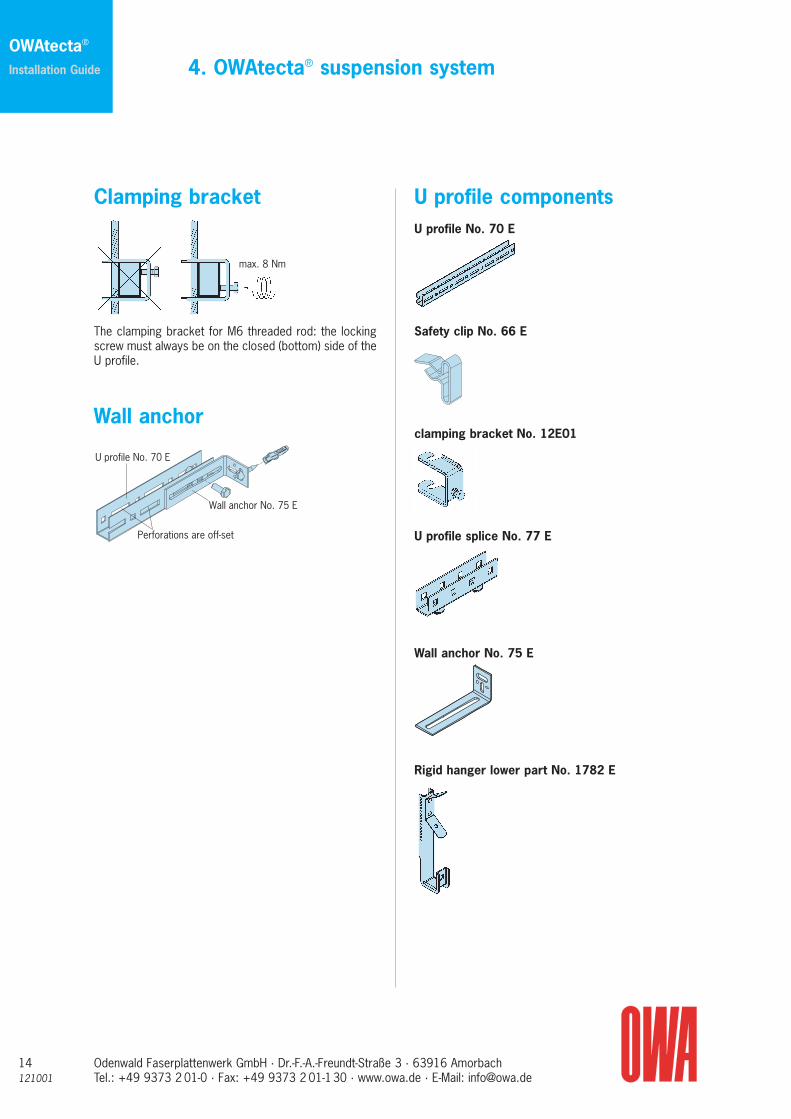
Clamping bracket
The clamping bracket for M6 threaded rod: the lockingscrew must always be on the closed (bottom) side of theU profile.
Wall anchor
4. OWAtecta® suspension system
U profile componentsU profile No. 70 E
Safety clip No. 66 E
clamping bracket No. 12E01
U profile splice No. 77 E
Wall anchor No. 75 E
Rigid hanger lower part No. 1782 E
OWAtecta®
Installation Guide
Wall anchor No. 75 E
U profile No. 70 E
Perforations are off-set
max. 8 Nm

121001Odenwald Faserplattenwerk GmbH · Dr.-F.-A.-Freundt-Straße 3 · 63916 AmorbachTel.: +49 9373 2 01-0 · Fax: +49 9373 2 01-130 · www.owa.de · E-Mail: [email protected]
Notes
15
OWAtecta®
Installation Guide

16121001
Odenwald Faserplattenwerk GmbH · Dr.-F.-A.-Freundt-Straße 3 · 63916 AmorbachTel.: +49 9373 2 01-0 · Fax: +49 9373 2 01-130 · www.owa.de · E-Mail: [email protected]
Main runner and hanger centres
1 Rigid hanger lower part No. 17/452 Main runner No. 45
at < 1250 mm centres3 Cross connector No. 93 C4 Clip-in profile No. 87 B5 Splice No. 88 E6 F-perimeter trim No. 50 F7 Wall spring No. 52208 Metal panel9 Removal tool No. 99005
Max installation centres for main runners and hangers < 1250mm
Cross-section:
Note: System S 31 / S 32 can also be used.
OWAtecta® clip-in systems
S 22 – Concealed, clip-in swing down
Direct fixing
Installation height up to underside of the ceiling panels54 – 60 mmHorizontal shift ca. +/- 50 mm
Installation height up to underside of the ceiling panels65 – 117 mmHorizontal shift ca. +/- 25 mm
1 Direct hanger No. 09E872 Clip-in profile No. 87 E
Edges
All edges bevelled (Edge 01)
OWAtecta®
Installation Guide
7.5
47
26
52
901
4
25
3 8
76
9 2
1
1
2

121001Odenwald Faserplattenwerk GmbH · Dr.-F.-A.-Freundt-Straße 3 · 63916 AmorbachTel.: +49 9373 2 01-0 · Fax: +49 9373 2 01-130 · www.owa.de · E-Mail: [email protected]
Perimeter optionsThe following perimeter trims are available:
C-profile No. 57 (steel, visible side white) in combination with wall springNo. 5210
F-stepped perimeter trim No. 5620 F (aluminium, visible side powder-coatedwhite) in combination withwall spring No. 5220
F-perimeter trim No. 50 F(aluminium, visible side white) in combination with wall springNo. 5220
The distance between the topsideof the U profile or T profile and theunderside of the metal panel can-not be adjusted. This means thatthe perimeter trims have to befixed precisely.
Installation and removal of panelsThe panels for the clip-in systems are manufactured withpips on two parallel edges to provide a friction con-nection with the clip-in profiles. The panels are pushedinto the clip-in profiles until an audible click is heard.
The removal or swinging down of the panels is onlypossible using the special removal tool No. 99005. The tool is pushed into the unclamped panel joint – directly next to the clip-in profile. The spring hinge of the tool must be on the side of the panel to be removed. After the spring has clicked into place in the panel edge, the panel can be carefully withdrawn from the clip-in profile. The same procedure is to be applied to the other panel edges.
OWAtecta® clip-in systems
S 22 – Concealed, clip-in swing down
Swinging down of panelsWith the exception of the perimeter ones all panels insystem S 22 "swing down"Where perimeter panels are required to be demountablethe swing down tabs of the panels should be removed.
17
OWAtecta®
Installation Guide
96
Remove tabs

18121001
Odenwald Faserplattenwerk GmbH · Dr.-F.-A.-Freundt-Straße 3 · 63916 AmorbachTel.: +49 9373 2 01-0 · Fax: +49 9373 2 01-130 · www.owa.de · E-Mail: [email protected]
OWAtecta® clip-in systems
S 31 – concealed, demountableS 32 – concealed, swing down
OWAtecta®
Installation Guide
Hangers Splice U profile
Hangers in vicinity of splice
2
1
1
2
Option 3:1 Rigid hanger lower part No. 1782 E 2 Adjustable hanger No. 14/.../1 or 14/.../23 Safety clip No. 66 E
Hanger rods must protrude through the adjustable bracket by at least 15mm.
Safety clip No. 66 E
The safety clip is inserted with the longer leg upwards andcan be easily removed using finger pressure.
Direct fixingU profile No. 70 E is not required when using direct fixbracket No. 09E87.
Installation height from theunderside of the ceiling panels66 – 72 mmHorizontal shift approx. +/- 25 mm
Installation height from theunderside of the ceiling panels73 – 129 mmHorizontal shift approx. +/- 25 mm
1 Direct fix bracket No. 09E872 Clip-in profile No. 87 E
If using wall anchor No. 75 E with the U profile, the firsthanger adjacent to the perimeter wall should be positio-ned ≤ half the distance of the normal hanger centres.Where no wall anchor is used the this distance should be≤ 300 mm from the end of the U profile.
Option 1
Option 2
Option 3
2
4
2
1
3
1
1
2
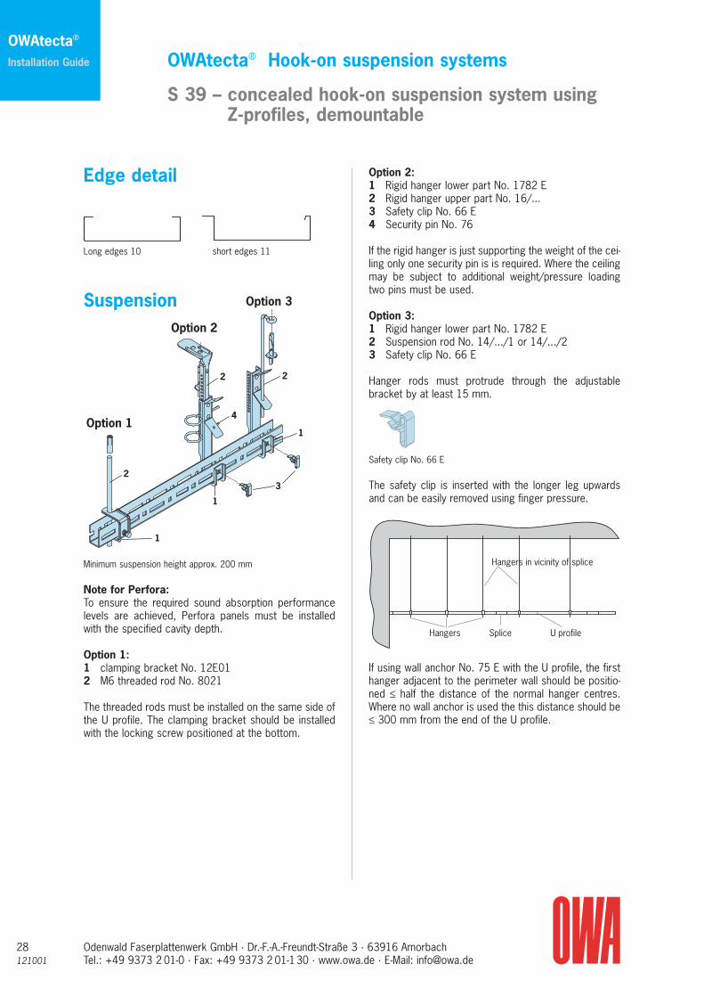
Edge detail
Edge 02 Edge 01
All edges bevelled (Edge 01) All edges square (Edge 02)
Suspension
Minimum suspension height approx. 200 mm
Note for Perfora: To ensure the required sound absorption performance levelsare achieved, Perfora panel must be installed with the specified cavity depth.
Option 1:1 clamping bracket No. 12E012 M6 threaded rod No. 8021
The threaded rods must always be installed on the sameside of the U profile. The clamping bracket should alwaysbe installed with the locking screw positioned at the bot-tom.
Option 2:1 Rigid hanger lower part No. 1782 E2 Rigid hanger upper part No. 16/...3 Safety clip No. 66 E4 Security pin No. 76
If the rigid hanger is just supporting the weight of the ceilingonly one security pin is is required. Where the ceiling may besubject to additional weight/pressure loading two pins mustbe used.

121001Odenwald Faserplattenwerk GmbH · Dr.-F.-A.-Freundt-Straße 3 · 63916 AmorbachTel.: +49 9373 2 01-0 · Fax: +49 9373 2 01-130 · www.owa.de · E-Mail: [email protected]
OWAtecta® clip-in systems
S 31 – concealed, demountableS 32 – concealed, swing down
19
OWAtecta®
Installation Guide
Wall anchor No. 75 E
U profile No. 70 E
Perforations are off-set
U Profile and hanger centres
1 Hangers2 U profile No. 70 E3 Splice No. 77 E4 Hanger bracket No. 11 E with safety clip No. 66 E5 clip-in profile No. 87 E6 Splice No. 88 E7 Wall anchor No. 75 E8 Wall spring No. 52209 F-perimeter trim No. 50 F
The U profile and hanger distances given in the tablebelow may not be exceeded. They refer only to the load from the ceiling suspension system and panels.Additional loads must generally be suspended sepa-rately.
Panel U profile Hangerlength ≤ distance T ≤ distance A ≤600 mm 1900 mm 1250 mm625 mm 1875 mm 1250 mm1250 mm 1350 mm 1250 mm1500 mm 1200 mm 1500 mm2000 mm 1050 mm 2000 mm2500 mm 850 mm 2500 mm
Wall anchor
After the U profiles have been aligned in both directions,each U-carrier row is fixed to the wall using wall anchorNo. 75 E. This wall anchor can be fixed to the side (asshown) or underneath the U profile.
U profile No. 70 E
U profile No. 70 E
Splice No. 77 E
Safety clip No. 66 E
1
24
3 5
7
6
89
T
A
Connector clipNo. 11 E
Safety clip No. 66 E
U profile No. 70 E
Clip-in rail No. 87 E
Splice No. 88 E(mount inside of clip-in rail)
Note:The U profiles should be installed so that the slots in thesides are in line with each other. To provide a degree of flexibility the slots are of different sizes and offset.
Connection of U profiles
The U profiles are connected by means of splice No. 77 Ewhich also provides a small degree of dimensional tolerance.The U profiles and splice bracket are joined together usingM6 bolts and safety clip No. 66 E. Joints in U profiles mustbe staggered.
Suspension and connectionof the clip-in profiles
The clip-in profiles hold the panels in place and are sus-pended from the U profile at the required module centresusing hanger bracket No. 11 E and safety clip No. 66 E.The clip-in profiles are joined together using splice No.88 E.
To avoid downward deflection of the ceiling, profile joints must be staggered.

20121001
Odenwald Faserplattenwerk GmbH · Dr.-F.-A.-Freundt-Straße 3 · 63916 AmorbachTel.: +49 9373 2 01-0 · Fax: +49 9373 2 01-130 · www.owa.de · E-Mail: [email protected]
OWAtecta® clip-in systems
S 31 – concealed, demountableS 32 – concealed, swing down
OWAtecta®
Installation Guide
Installation and removal of panelsThe panels for the clip-in systems are manufactured withpips on two parallel edges to provide a friction connec-tion with the clip-in profiles. The panels are pushed intothe clip-in profiles until an audible click is heard.
The removal or swinging down of the panels is onlypossible with the special removal tool No. 99005. The tool is pushed into the unclamped panel joint – directly next to the clip-in profile. The spring hinge of the tool must be on the side of the panel to be removed. After the spring has clicked into place in the panel edge, the panel can be carefully withdrawn from the clip-in profile. The same procedure is to be applied to the other panel edges.
Swinging down of panelsIndividual panels can be selected to swing down insystem S 31. For this, the hinge-down clip No. 86 E,must be clipped onto clip-in profile No. 87 E at the paneljoint. Both adjacent panels in the same row can then beswung down towards each other. If a hinge-down clip islikewise arranged on the next but one panel joint, an areathe size of two panels can be opened in the ceiling byswinging down.
The panels are provided with so-called hinge tabs at the clamped edges to ensure a neat panel joint. In the case of swing down panels, the hinge tabs in the region of the hinge-down clip must be bent.
In the case of linear panels, it is the other way round, i.e. if they are not to be swung down, the hinge tabs have tobe pressed inwards.System S 32 differs from S 31 only by every second paneljoint being equipped with a hinge-down clip. As a result, allpanels can be swung down. By gently pushing swung downpanels together the open space can be made even larger.
Hingetabs
No.68 E
No.86E01
96
Wind safety/SecurityThe panels can be secured against displacement – e. g. inthe case of increased wind pressure – with the help ofsecurity-bracket No. 68 E. The security clip is inserted through the hole in the two adjacent panels and clipped over the clip-in profile. Two security clips are required per panel. Once secured the panels are not demountable.
The hinge down clip used in System S 32 can also be secured using clip No. 86E01. Tiles can still be swung down.
Perimeter optionsThe distance between the upper U profile edge and underside of the ceilings panels is 96 mm and cannot be adjusted. This means that the perimeter trims have to be fixed precisely.
The following perimeter trim versions are available:
C-perimeter trim No. 57(steel, visible side white) in combination with wall springNo. 5210
Stepped perimeter trim No. 5620 F(aluminium, visible side powder-coated white) in combination withwall spring No. 5220
F-perimeter trim No. 50 F (aluminium, visible side white) in combination with wall spring No. 5220
Panels which are supported by a perimeter trim cannotbe removed directly or swung down. Consequently, in thecase of smaller or narrow areas at least three panels perinstallation row are required so that initially the penulti-mate panel and then the wall panel can be demounted.
See OWAtecta® brochure 300 for additional perimetertrims and information on installation.

121001Odenwald Faserplattenwerk GmbH · Dr.-F.-A.-Freundt-Straße 3 · 63916 AmorbachTel.: +49 9373 2 01-0 · Fax: +49 9373 2 01-130 · www.owa.de · E-Mail: [email protected]
OWAtecta® clip-in systems
S 31 – concealed, demountableS 32 – concealed, swing down
21
OWAtecta®
Installation Guide
Clean-room clamp No. 99007
Sealing tapeNo. 8900
96146
59.5
19.5
Installation of lightingOWA supplies compatible integrated lighting for thissystem.
Versions: OWA-LexOWA-TerraOWA-Opta
Dimensions: 600 mm x 600 mm625 mm x 625 mm
For details on installation and fire protection of lighting,see brochure No. 630.
Down-lights:OWA supplies compatible down-lights for this system.For details on installation and provision of fire resistancefor lights see brochure No. 632.
General notes:Clip-in panels with integrated lighting as a compact com-ponent are available for systems S 31 and S 32.
If the location point of the lighting to be installed is notknown, connector clip No. 12 E can be used as an alter-native to Hanger bracket No. 11E– provided the voidheight permits this.
The distance between the top edge of U profile No. 70 Eand the underside of the metal panels is then 146 mminstead of 96 mm. As a result most lighting can be insta-lled irrespective of the location of the U profiles.
Clean room ceilingWhen used in system S 31 plain un-perforated metalpanels can be used to satisfy most clean room require-ments (cf. OWA brochure No. 895 – ceilings for cleanrooms).
For this it is necessary
• to slide on at least on clamp No. 99007 per panel joint(see sketch)
• install wall spring clips on all perimeter panels usingone clip ≤ 30 cm ( minimum 1 per panel)
• to ensure where walls or partitions are uneven that thejunction between the wall and trim is sealed using asuitable sealant (e. g. acrylic).
Perimeter OptionsPerimeter Channel No. 57 with retaining spring clips No. 5210
Perimeter trim No. 50F with retaining spring clips No. 5220
Note:We can also provide clip-in panels with integrated cleanroom lighting (protection class IP54, see brochure 630).
For more project specific information or guidance on theinstallation of clean room ceilings please contact OWA.

22121001
Odenwald Faserplattenwerk GmbH · Dr.-F.-A.-Freundt-Straße 3 · 63916 AmorbachTel.: +49 9373 2 01-0 · Fax: +49 9373 2 01-130 · www.owa.de · E-Mail: [email protected]
OWAtecta® Lay-in Systems
S 33 – exposed, demountable, 24 mmS 45 – exposed, demountable, 15 mm
OWAtecta®
Installation Guide
Note for Perfora: To ensure the required sound absorption performancelevels are achieved, Perfora panel must be installed withthe specified cavity depth.
Installation of the suspension system
1 Hanger No. 12/… /…2 Main runner No. 45 or 45/15 G
slotted o/c at 100 or 156.25 mm*3 Cross tee No. 46 or No. 46/15 G4 Cross tee No. 47 or No. 47/15 G5 Perimeter trim No. 576 Wall spring No. 5210
* 100 mm for metric sizes (600 mm) and 156.25 mm for DIN sizes (625 mm)
Installation possibilitiesExample with 625 mm module
Main runner distance Main runner distance= 625 mm = 1250 mmHanger spacing Hanger spacing ≤ 1500 mm ≤ 1250 mm
2
4
1
3 5
6
625 1250
≤ 12
50
≤ 15
00
The different edge details
S 33
Edge 03 Edge 07 Edge 04
S 45
Edge 03 Edge 16
Suspension
Adjustable hangers Rigid hangersNo. 12/.../1 hook/hook No. 17/45 with extensionNo. 12/.../2 eye/hook No. 16/... and Security pin
No. 76 or nail No. 78Minimum suspension height Minimum suspension heightapprox. 130 mm approx. 240 mmEnds of upper and lower The overhang of the nail is hanger rods must protrude to be bent over after through the adjustable levelling is finished.bracket by at least 15 mm.
If the rigid hanger is just supporting the weight of the cei-ling only one security pin is is required. Where the ceilingmay be subject to additional weight/pressure loadingtwo pins must be used. The minimum suspension heightfor easy installation and removal of panels is 120 mm.
For more suspension options see OWAconstruct® con-struction parts and accessory price list.
Additional loads must be suspended independently.

121001Odenwald Faserplattenwerk GmbH · Dr.-F.-A.-Freundt-Straße 3 · 63916 AmorbachTel.: +49 9373 2 01-0 · Fax: +49 9373 2 01-130 · www.owa.de · E-Mail: [email protected]
OWAtecta® Lay-in Systems
S 33 – exposed, demountable, 24 mmS 45 – exposed, demountable, 15 mm
23
OWAtecta®
Installation Guide
Expansion joint
Main runners
No. 45
Main runner No. 45 is equipped at both ends with inte-grated splice connection that produce a high tensileconnection.
A hanger should always be positioned close to thejoint and joints should be staggered.
Expansion joint:
Every main runner is equipped with a standard expansion joint at one end, which serves to accommodate linear expansion in the event of fire.
The main runners must be so arranged that no expansionjoints are adjacent to each other. No load transfers (han-gers, light attachments …) are to be fitted to the expansi-on joint.
When setting up the first main runner row, it must be ensured that:– the distance to the wall corresponds to the length
(width) of the perimeter panel.– the distance of the slot for the insertion of the cross
tee to the wall corresponds to the width (length) of theperimeter panel.
The main runners can be installed almost without waste,i. e. most off-cuts can be used at the beginning of the next row of main runners, automatically creatingstaggered joints (see previous). The main runners are
supported by perimeter trim and should be cut short ofthe wall by 5 mm or 1/4 of the width of the perimetertrim, whichever is less.
Cross tees
Cross teeNo. 46 or No. 47
In conjunction with the main runner the cross tees areused to create the required module. They are equiped atboth ends with off-set hook connectors that are insertedinto the main runner slots.
Care must be taken to – insert the connectors in the correct side of the slot
(see diagram above).– ensure the cross tee expansion nose is not bent.– ensure the visible surfaces of the profiles are flat and
level.
Cross tees No. 46 or No. 47 are off-set to the left. Crosstees No. 47 and No. 47/15 G are slotted in the middlefor the insertion of additional cross tees.Perimeter cross tees are supported by the perime-ter trim and should be cut short of the wall by 5 mm or 1/4 of the width of the perimeter trim,whichever is less.
Additional hangers must be used to compensate for anyadditional loads placed on the cross tees.
38
1515
3832
38
24 24
dimensions:
S 33 S 45
No. 46, No. 45 No.46/15 G No. 45/15 GNo. 47 No.47/15 G

24121001
Odenwald Faserplattenwerk GmbH · Dr.-F.-A.-Freundt-Straße 3 · 63916 AmorbachTel.: +49 9373 2 01-0 · Fax: +49 9373 2 01-130 · www.owa.de · E-Mail: [email protected]
OWAtecta® Lay-in Systems
S 33 – exposed, demountable, 24 mmS 45 – exposed, demountable, 15 mm
OWAtecta®
Installation Guide
Integrated lighting
OWA supplies compatible integrated lighting for thissystem (OWA Lex, OWA Terra, OWA Opta) in the dimen-sions 600 x 600 mm and 625 x 625 mm. This lightingcan be installed in place of a panel in the supportingstructure.
The lighting must be independently suspended or addi-tional hangers must be installed to compensate for theadditional loading where appropriate.
Down-lights must in general be suspended indepen-dently. The required panel cut-outs can be includedduring manufacturing provided they are ordered togetherwith the panels.
Electrical cables are not to be laid onto the ceiling or suspension system.
Coordination with the electrical planner or installeris important to enable the installation of additional orindependent suspension. Experience shows that theinstallation of hangers retrospectively is more difficult,more expensive and they are therefore more likely to beomitted leaving a potentially serious, concealed defect.
Perimeter options
Depending on the edge detail of the panels, various perimeter trims are available:
For edge 03 and edge 04
C-perimeter trim No. 57(steel, visible side white) in combi-nation with wall spring No. 5210
F-perimeter trim No. 50 F(aluminium, visible side white) in combination with wall spring No. 5220
F-stepped perimeter trim No. 5620 F(aluminium, visible side powder-coated white) in combination withwall spring No. 5220
For edge 07
F-stepped perimeter trim No. 5015 F(aluminium, visible side powder-coated white) in combination withwall spring No. 5220
F-perimeter trim No. 50 F(aluminium, visible side white) in combination with wall spring No. 5220
Depending on panel-type and perimeter trim, the mainrunners and cross tees may have to be suspended nearthe walls when they run above the perimeter trim.
Correct installation of the edge panel in combination with F-perimeter trim and wall spring
See OWAtecta® brochure 300 (price list) for additionalperimeter trims and information on installation.

121001Odenwald Faserplattenwerk GmbH · Dr.-F.-A.-Freundt-Straße 3 · 63916 AmorbachTel.: +49 9373 2 01-0 · Fax: +49 9373 2 01-130 · www.owa.de · E-Mail: [email protected]
OWAtecta® Corridor systems
S 36 – Success (clip-in profile)
25
OWAtecta®
Installation Guide
Carrier angleNo. 5110 E
Hanger bracketNo. 1387 E
Clip-in railNo. 87 E
Metal panel
S 36 Success
Panels can be swung down along the long side orindividually removed.
Edge detail
Long: edge 10 Short: edge 02
Fixing centres:Carrier angle No. 5110 E: 500 mm (angle pre-drilled)Hanger No. 1387 E: 500 mm (angle pre-drilled)
Minimum suspension height:The carrier angles can be mounted directly under thesoffit. Please take account of possible lighting height.
Please note that the carrier angles must be fixed exactlyat the required height. There is no additional adjustmentpossible. The clip-in profiles can be shifted +/- 10 mmhorizontally.Note: In some panels the tabs stamped into the ends ofthe panel’s long side have to be pressed inwards.
Installation and removal of panelsThe panels for the clip-in systems are manufactured withpips on two parallel edges to provide a friction connec-tion with the clip-in profiles. The panels are pushed intothe clip-in profiles until an audible click is heard.
The removal or swinging down of the panels is only pos-sible with a special tool, the removal tool No. 99005. The tool is pushed into the unclamped panel joint – directly next to the clip-in profile. The spring hinge of the tool must be on the side of the panel to be removed. After the spring has clicked into place in the panel edge, the panel can be carefully withdrawn from the clip-in profile. The same pro-cedure is to be applied to the other panel edges.
Swinging down of panelsIndividual panels or all of them can be selected to swingdown in system S 36. For this wire clip No. 69 E, that serves as hinge, must be introduced into the hole on thepanel’s long side and clipped onto the clip-in profile No. 87E (see illustration).
Up to three swing down panels can be pushed next toeach other on the clip-in profile to enlarge the openingarea. If the wire clips are arranged on the panel’s jointsopposite each other, a ceiling area twice as big can be opened thanks to the swing down action in oppositedirections.
Note: Panels cannot be removed when in the swung down positi-on. Where a panel is to be removed the wire clip No. 69 Emust be un-clipped before the the panel is moved
Carrier angleNo. 5110 E
Bolt and nut M6 x 12
HangersNo. 1387 E
Clip-in railNo. 87 E
78
18 - 38 18 - 38Panel length

26121001
Odenwald Faserplattenwerk GmbH · Dr.-F.-A.-Freundt-Straße 3 · 63916 AmorbachTel.: +49 9373 2 01-0 · Fax: +49 9373 2 01-130 · www.owa.de · E-Mail: [email protected]
OWAtecta® Corridor systems
S 36 – Swing (G-section)
OWAtecta®
Installation Guide
S 36 Swing
Panels can be swung down along the long side orindividually removed.
Edge detail
Long: edge 10 Short: edge 32
Fixing centres:Wall bracket No. 99008: 500 mm(G-section 5109E has linear perfo-rations at 500 mm centres)
As an alternative in place of the wall bracket, carrierangle No. 5110 E can be installed (see version shownbelow). In this case no height adjustment is possible.
Wall bracketNo. 99008
G-section No. 5109 E
Metal panels
Carrier angleNo. 5110 E G-section
No. 5109 E
metal panel
60
40
Sliding coupling Spring
Installation and removal of panelsThe panels for this system are provided with sliding coup-lings at the ends of one long side, which when extendedrest on the G-section. At the ends of the opposite longedges spring clips are mounted, which project throughslots on the short sides and rest on the G-section.
Installation procedure:• Check joint tape is on three panel sides• Retract sliding couplings• With the sliding coupling side up, push the panel diago-
nally up between the G-section. • Extend sliding coupling until they click into place and
rest them on the G section. Panel is now in the “swingdown” position.
• Carefully push the other edge of panel up until thespring clips into place (for ease of installation it maybe necessary to depress the springs).
Swing down/demount:
To swing down or demount the panel, removal tool No.99005 is required.
Insert removal tool No. 99005 between the G-section/panel and locate spring clip.
Slide the removal tool along either side of the panel untilthe spring clips have been compressed and the frontedge of the panel freed.
Gently pull the panel down into the the "swing down" posi-tion.
To remove completelyretract the slidingcouplings and removepanel.
Removal tool,putty knife etc

121001Odenwald Faserplattenwerk GmbH · Dr.-F.-A.-Freundt-Straße 3 · 63916 AmorbachTel.: +49 9373 2 01-0 · Fax: +49 9373 2 01-130 · www.owa.de · E-Mail: [email protected]
OWAtecta® Corridor systems
S 36 – Progress (Z-profile)
27
OWAtecta®
Installation Guide
Bracket No. 12E02with safety clip No. 66 E
Metal panel
U profileNo. 70 E
Wall anchorNo. 75 E
Z-profile No. 90 E
S 36 Progress
Panels can be swung down or individually removed.
Edge detail
Long: edge 10 Short: edge 11s
Version 1
Version 1: U profiles No. 70 E are fixed to the wall using wallanchors No. 75 E. When using this version the distance between the wall and panel is not critical but must be suffi-cient to allow installation of panels.
U profiles No. 70 E are connected using splice No. 77 E(see page 13 for details).
Z profiles are fixed to the U profile using connector bracketNo. 12E02 secured to the U profile using safety clip No. 66E. Once the Z profiles have been located in the bracket thelocking flaps should be bent down to secure the Z. Whenusing wall anchor No. 75 E or bracket No. 99008 use M6nuts and bolts to connect the Z profiles.It is important to ensure that all the profiles are installedaccurately and level.
If using bracket No. 12E02 to sup-port the Z profile the distance (a)must be ≥ 80 mm. If less than 80mm version 2 or 3 should be used.
Version 2
To install the panels a minimum distance of 10-15 mm isrequired between the wall and the panel. When this distanceis less than 12 mm wall anchor No. 75 E or bracket No. 99008 should be used.
Version 3
Version 3: L profile No. 5110 E is fixed to the wall at the appro-priate level and the Z profile bolted below using M6 nuts andbolts at 50 cm centres. Both profiles are supplied with pre-drilled holes at 50 cm centres. The L profile is 45 mm wide andallows panels to be removed but not hinged down.
Hinge down and/or remove panelsTo install or remove the panels there must be a minimumdistance between the panel and the wall of at least 10 mmone end and 15 mm the other. To allow the panels to hingedown there must be a minimum distance of 40 mm betweenthe wall and panels.
Bracket No. 12E02 withsafety clip No. 66 E
SpliceNo. 25 E
U profileNo. 70 E
Z-profile No. 90 E
Bend down flapsto secure 90 E to 70 E
> 10 Panel length > 10
60
> 10> 40
min. 5
Hingeddownpanel
a
28121001
Odenwald Faserplattenwerk GmbH · Dr.-F.-A.-Freundt-Straße 3 · 63916 AmorbachTel.: +49 9373 2 01-0 · Fax: +49 9373 2 01-130 · www.owa.de · E-Mail: [email protected]
OWAtecta® Hook-on suspension systems
S 39 – concealed hook-on suspension system using Z-profiles, demountable
OWAtecta®
Installation Guide
Hangers Splice U profile
Hangers in vicinity of splice
Option 1
Option 2
Option 3
2
4
2
1
3
1
1
2
Edge detail
Long edges 10 short edges 11
Suspension
Minimum suspension height approx. 200 mm
Note for Perfora: To ensure the required sound absorption performancelevels are achieved, Perfora panels must be installedwith the specified cavity depth.
Option 1:1 clamping bracket No. 12E012 M6 threaded rod No. 8021
The threaded rods must be installed on the same side ofthe U profile. The clamping bracket should be installedwith the locking screw positioned at the bottom.
Option 2:1 Rigid hanger lower part No. 1782 E2 Rigid hanger upper part No. 16/...3 Safety clip No. 66 E 4 Security pin No. 76
If the rigid hanger is just supporting the weight of the cei-ling only one security pin is is required. Where the ceilingmay be subject to additional weight/pressure loadingtwo pins must be used.
Option 3:1 Rigid hanger lower part No. 1782 E 2 Suspension rod No. 14/.../1 or 14/.../23 Safety clip No. 66 E
Hanger rods must protrude through the adjustable bracket by at least 15 mm.
Safety clip No. 66 E
The safety clip is inserted with the longer leg upwardsand can be easily removed using finger pressure.
If using wall anchor No. 75 E with the U profile, the firsthanger adjacent to the perimeter wall should be positio-ned ≤ half the distance of the normal hanger centres.Where no wall anchor is used the this distance should be≤ 300 mm from the end of the U profile.

121001Odenwald Faserplattenwerk GmbH · Dr.-F.-A.-Freundt-Straße 3 · 63916 AmorbachTel.: +49 9373 2 01-0 · Fax: +49 9373 2 01-130 · www.owa.de · E-Mail: [email protected]
OWAtecta® Hook-on suspension systems
S 39 – concealed hook-on suspension system using Z-profiles, demountable
29
OWAtecta®
Installation Guide
Wall anchor No. 75 E
U profile No. 70 E
Perforations are off-set
U profile No. 70 E
U profile No. 70 E
Splice No. 77 E
Safety clip No. 66 E
U profile and hanger centres
1 Hanger No. 1782 E2 U profile No. 70 E3 Splice No. 77 E4 Connector clip No. 12E025 Safety clip No. 66 E6 Z-profile No. 90 E
Splice No. 25 E (not shown)8 Wall spring No. 52209 Wall anchor No. 75 E10 F-perimeter trim No. 50 F
The U profile and hanger centres given in the table belowmust not be exceeded. They only take into account theweight of the ceiling suspension system and metal cei-ling panels. Additional loads must be suspended sepa-rately.
Panels U-Carrier Hangerslength ≤ centre T ≤ centre A ≤600 mm 1900 mm 1250 mm625 mm 1875 mm 1250 mm1250 mm 1350 mm 1250 mm1500 mm 1200 mm 1500 mm2000 mm 1050 mm 2000 mm2500 mm 850 mm 2500 mm
Connection of U profile
The U profiles are connected by means of splice No. 77E which also provides a small degree of dimensional tole-rance. The U profiles and splice bracket are joined to-
108
9
1
5
5
4
6
3
2
gether using M6 bolts and safety clip No. 66 E. U profiles joints must be staggered.
Wall anchor
After the U profiles have been aligned in both directions,each U-carrier row is fixed to the wall using wall anchorNo. 75 E. This wall anchor can be fixed to the side (asshown) or underneath the U profile.
Note: The U profiles should be installed so that the slotsin the sides are in line with each other. To provide adegree of flexibility the slots are of different sizes andoffset.
Suspension and connectionof the Z-profile
The Z profile should be installed at the correct centresfor the specified panel and are attached to the U profileusing connector bracket No. 12E02. Once in positionthe connector is fixed using safety clip No. 66 E and theZ profile secured by folding the connector bracket tabsdown (see diagram).
The Z profiles are joined together using splice No. 25 E.Joints in adjacent Zed profiles must be staggered.
Bracket No. 12E02 withsafety clip No. 66 E
SpliceNo. 25 E
U profileNo. 70 E
Z-profile No. 90 E
Bend down flapsto secure 90 E to 70 E
30121001
Odenwald Faserplattenwerk GmbH · Dr.-F.-A.-Freundt-Straße 3 · 63916 AmorbachTel.: +49 9373 2 01-0 · Fax: +49 9373 2 01-130 · www.owa.de · E-Mail: [email protected]
OWAtecta® Hook-on suspension systems
S 39 – concealed hook-on suspension system using Z-profiles, demountable
OWAtecta®
Installation Guide
Anti-uplift clamp No. 67 E
Z-profile No. 90 E
Thickness of sealing tape
~ 6
1 m
m 92 m
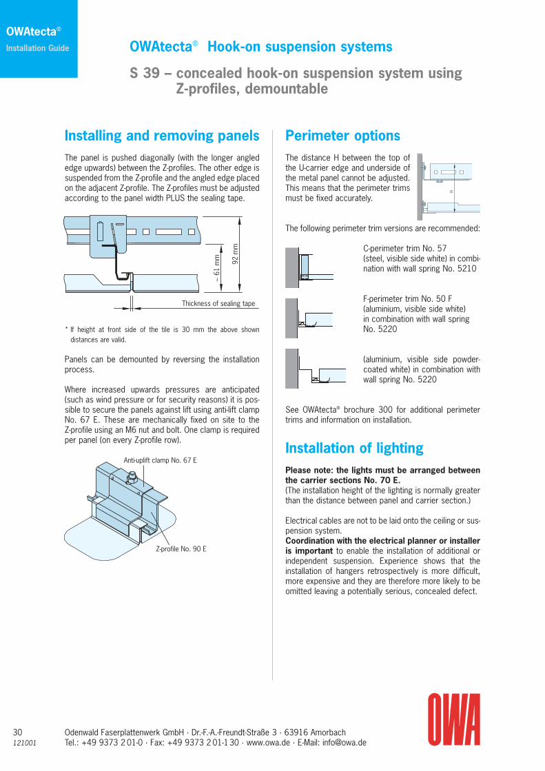
m
Installing and removing panelsThe panel is pushed diagonally (with the longer anglededge upwards) between the Z-profiles. The other edge issuspended from the Z-profile and the angled edge placedon the adjacent Z-profile. The Z-profiles must be adjustedaccording to the panel width PLUS the sealing tape.
* If height at front side of the tile is 30 mm the above showndistances are valid.
Panels can be demounted by reversing the installationprocess.
Where increased upwards pressures are anticipated(such as wind pressure or for security reasons) it is pos-sible to secure the panels against lift using anti-lift clampNo. 67 E. These are mechanically fixed on site to theZ-profile using an M6 nut and bolt. One clamp is requiredper panel (on every Z-profile row).
Perimeter options The distance H between the top ofthe U-carrier edge and underside ofthe metal panel cannot be adjusted.This means that the perimeter trimsmust be fixed accurately.
The following perimeter trim versions are recommended:
C-perimeter trim No. 57(steel, visible side white) in combi-nation with wall spring No. 5210
F-perimeter trim No. 50 F(aluminium, visible side white) in combination with wall spring No. 5220
(aluminium, visible side powder-coated white) in combination withwall spring No. 5220
See OWAtecta® brochure 300 for additional perimetertrims and information on installation.
Installation of lightingPlease note: the lights must be arranged betweenthe carrier sections No. 70 E.(The installation height of the lighting is normally greaterthan the distance between panel and carrier section.)
Electrical cables are not to be laid onto the ceiling or sus-pension system.Coordination with the electrical planner or installeris important to enable the installation of additional orindependent suspension. Experience shows that theinstallation of hangers retrospectively is more difficult,more expensive and they are therefore more likely to beomitted leaving a potentially serious, concealed defect.
H
121001Odenwald Faserplattenwerk GmbH · Dr.-F.-A.-Freundt-Straße 3 · 63916 AmorbachTel.: +49 9373 2 01-0 · Fax: +49 9373 2 01-130 · www.owa.de · E-Mail: [email protected]
OWAtecta® Linear C-bandraster systems
S 48 – demountable– swing down along the long edge
31
OWAtecta®
Installation Guide
Hangers Splice U profile
Hangers in vicinity of splice
Option 1
Option 2
Option 3
2
4
2
1
3
1
1
2
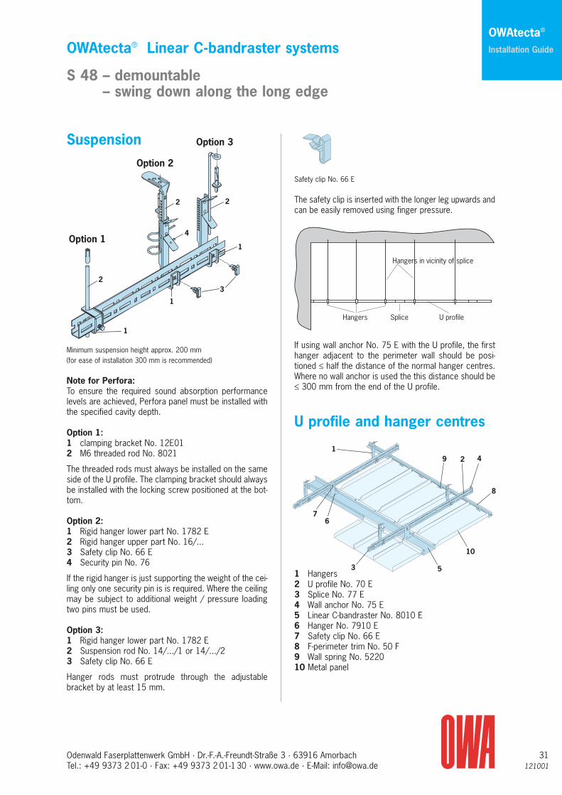
Suspension
Minimum suspension height approx. 200 mm(for ease of installation 300 mm is recommended)
Note for Perfora: To ensure the required sound absorption performancelevels are achieved, Perfora panel must be installed withthe specified cavity depth.
Option 1:1 clamping bracket No. 12E012 M6 threaded rod No. 8021
The threaded rods must always be installed on the sameside of the U profile. The clamping bracket should alwaysbe installed with the locking screw positioned at the bot-tom.
Option 2:1 Rigid hanger lower part No. 1782 E2 Rigid hanger upper part No. 16/...3 Safety clip No. 66 E 4 Security pin No. 76
If the rigid hanger is just supporting the weight of the cei-ling only one security pin is is required. Where the ceilingmay be subject to additional weight / pressure loadingtwo pins must be used.
Option 3:1 Rigid hanger lower part No. 1782 E2 Suspension rod No. 14/.../1 or 14/.../23 Safety clip No. 66 E
Hanger rods must protrude through the adjustable bracket by at least 15 mm.
Safety clip No. 66 E
The safety clip is inserted with the longer leg upwards andcan be easily removed using finger pressure.
If using wall anchor No. 75 E with the U profile, the firsthanger adjacent to the perimeter wall should be posi-tioned ≤ half the distance of the normal hanger centres.Where no wall anchor is used the this distance should be≤ 300 mm from the end of the U profile.
U profile and hanger centres
1 Hangers2 U profile No. 70 E3 Splice No. 77 E4 Wall anchor No. 75 E5 Linear C-bandraster No. 8010 E6 Hanger No. 7910 E7 Safety clip No. 66 E8 F-perimeter trim No. 50 F9 Wall spring No. 522010 Metal panel
19 2 4
8
10
53
67

32121001
Odenwald Faserplattenwerk GmbH · Dr.-F.-A.-Freundt-Straße 3 · 63916 AmorbachTel.: +49 9373 2 01-0 · Fax: +49 9373 2 01-130 · www.owa.de · E-Mail: [email protected]
OWAtecta® Linear C-bandraster systems
S 48 – demountable– swing down along the long edge
OWAtecta®
Installation Guide
U profile No. 70 E
U profile No. 70 E
Splice No. 77 E
Safety clip No. 66 E
Wall anchor No. 75 E
U profile No. 70 E
Perforations are off-set
The U profile and hanger centres given in the table belowmust not be exceeded. They refer only to the load causedby the ceiling suspension system and panels. Additionalloads must be suspended separately.
Panel U profile Hangerlength ≤ centre T ≤ dentre A ≤600 mm 1900 mm 1250 mm625 mm 1875 mm 1250 mm1250 mm 1350 mm 1250 mm1500 mm 1200 mm 1500 mm2000 mm 1050 mm 2000 mm2500 mm 850 mm 2500 mm
Wall anchor
After the U profiles have been aligned in both directions,each U-carrier row is fixed to the wall using wall anchorNo. 75 E. This wall anchor can be fixed on the side (asshown) or underneath the U profile.
Note: The U profiles should be installed so that the slotsin the sides are in line with each other. To provide adegree of flexibility the slots are of different sizes andoffset.
Connection of U profiles
The U profiles are connected by means of splice No. 77E which also provides a small degree of dimensional tole-rance. The U profiles and splice bracket are joined to-gether using M6 bolts and safety clip No. 66 E. Joints inU profiles must be staggered.
Suspension and connectionof the linear C-bandraster
Linear C bandrasters are installed parallel at the speci-fied centres and suspended from the U profiles usinghanger No. 7910 E and security clip No. 66 E. Band-rasters are joined together using splice No. 8210 E and fixed to perimeter walls using using wall anchor No. 8110 E (wall anchors should not be screw fixed to bandraster).Bandraster joints must be staggered between rows.
Please note:The minimum clearance between linear C-band-raster and the wall is to be 10 mm. The maximumclearance depends on the type and width of theperimeter trim used.
Wall anchor No. 8110 E Hangers
U profile No. 70 E
Linear C-bandrasterNo. 8010 E
Safety clip No. 66 E
Hanger No. 7910 E
Splice No. 8210 E

121001Odenwald Faserplattenwerk GmbH · Dr.-F.-A.-Freundt-Straße 3 · 63916 AmorbachTel.: +49 9373 2 01-0 · Fax: +49 9373 2 01-130 · www.owa.de · E-Mail: [email protected]
OWAtecta® Linear C-bandraster systems
S 48 – demountable– swing down along the long edge
33
OWAtecta®
Installation Guide
S 48 Easy
Edge detail
Long edge 10 Short edges 13 A
Installation and removal• Check whether there is joint tape on three panel sides
– add if necessary• Push the panel diagonally between the linear C-band-
raster• Lay the short edges of the panels onto the linear C-band-
raster (see diagram)
Swinging down of panels• Remove panel• Push the panel on-end (see presentation) between the
linear C-bandraster• Suspend the panel with the front end lugs from the
linear C-bandraster
3 3
65
95
S 48 SwingSwing down along the linear edgeor individually demountable
Edge detail
Long edge 10 Short edge 32
Installation procedure:• Check joint tape is on three panel sides• Retract sliding couplings• With the sliding coupling side up, push the panel diago-
nally up between the C bandraster. • Extend sliding coupling until they click into place and
rest them on the C Bandraster. Panel is now in the“swing down” position.
• Carefully push the other edge of panel up until thespring clips into place (for ease of installation it may benecessary to depress the springs).
Swing down/removal:Insert removal tool No. 99005 between the C bandraster/panel and locate spring.
Slide the removal tool along either side of the panel untilthe springs have been compressed and the front edge ofthe panel freed.
Gently pull the panel down into the the "swing down" posi-tion.
To remove completely retract the sliding couplings andremove panel.
3 3
65
95
Sliding coupling on each square edge
Sliding coupling Spring

34121001
Odenwald Faserplattenwerk GmbH · Dr.-F.-A.-Freundt-Straße 3 · 63916 AmorbachTel.: +49 9373 2 01-0 · Fax: +49 9373 2 01-130 · www.owa.de · E-Mail: [email protected]
OWAtecta® Linear C-bandraster systems
S 48 – demountable– swing down along the long edge
OWAtecta®
Installation Guide
Swing-down panels can be pushed together.
Perimeter options:To allow use of wall anchor No. 75100 E only perimetertrims with a maximum height of 30 mm can be used withsystems S 48 and S 50.Where stepped perimeter trims are used the overallwidth should not exceed 30 mm.
Perimeter trims should be fixed at ≤ 300 mm centres.
Joint tape:Where requested the panels can be supplied with selfadhesive joint tape No. 99308 (3 x 8 mm) on one longedge and two short edges. If applying tape on site thepanels must be installed with one joint tape at eachpanel/panel and panel/bandraster junction
Putty knife etc
30
30
Wall anchor and cross connector No. 8110 E
Linear C-bandraster No. 8010 E
F-perimeter trim No. 50 F

121001Odenwald Faserplattenwerk GmbH · Dr.-F.-A.-Freundt-Straße 3 · 63916 AmorbachTel.: +49 9373 2 01-0 · Fax: +49 9373 2 01-130 · www.owa.de · E-Mail: [email protected]
OWAtecta® C-bandraster systems
S 50 – C-bandraster with junction box– demountable– can be swung down along the long edge
35
OWAtecta®
Installation Guide
1 Threaded rod No. 80212 Junction box No. 81100 E3 Linear C-bandraster No. 80100 E4 Wall anchor No. 75100 E5 F-perimeter trim No. 50 F6 Wall spring No. 5220
The junction box is suspended using threaded rod No. 8021 and nuts. As there is no horizontal adjustment,the hangers must be installed vertically at set centres to create a stress free installation.
Note for Perfora: To ensure the required sound absorption performancelevels are achieved, Perfora panels must be installedwith the specified cavity depth.
The following table shows the maximum centres for junction boxes and C-bandraster, The spans are basedon the ceiling load only. Additional loads must be in-dependently supported.
Hanger centres
qF:Weight of the ceiling
a0:Distance betweenjunction boxes
a2:Distance betweenLinear C-band-raster
x:Maximum lengthof perimeter C-bandraster≤ 1200 mm
Note:Additionalhanger must be used for C-bandrasterover 1900 mm in length(see additionalsuspensions)
qF qF + 4 kg/m2
a2 [m] [0,083 kN/m2] [0,123 kN/m2]a0 [m] a0 [m]
0.50 1.90 1.900.55 1.90 1.900.60 1.90 1.900.65 1.90 1.900.70 1.90 1.900.75 1.90 1.900.80 1.90 1.900.85 1.90 1.850.90 1.90 1.800.95 1.90 1.801.00 1.90 1.751.05 1.90 1.701.10 1.90 1.701.15 1.90 1.651.20 1.90 1.651.25 1.85 1.601.30 1.85 1.601.35 1.80 1.601.40 1.80 1.551.45 1.75 1.551.50 1.75 1.501.55 1.70 1.501.60 1.70 1.501.65 1.70 1.501.70 1.65 1.451.75 1.65 1.451.80 1.65 1.451.85 1.60 1.401.90 1.60 1.401.95 1.60 1.402.00 1.60 1.402.05 1.55 1.352.10 1.55 1.352.15 1.55 1.352.20 1.55 1.352.25 1.50 1.352.30 1.50 1.302.35 1.50 1.302.40 1.50 1.302.45 1.45 1.302.50 1.45 1.302.55 1.45 1.252.60 1.45 1.252.65 1.45 1.252.70 1.45 1.252.75 1.40 1.252.80 1.40 1.252.85 1.40 1.252.90 1.40 1.202.95 1.40 1.203.00 1.40 1.20
a0
a2
x
2
1
4
3
1
2
3
4
5
6

36121001
Odenwald Faserplattenwerk GmbH · Dr.-F.-A.-Freundt-Straße 3 · 63916 AmorbachTel.: +49 9373 2 01-0 · Fax: +49 9373 2 01-130 · www.owa.de · E-Mail: [email protected]
OWAtecta® C-bandraster systems
S 50 – C-bandraster with junction box– demountable– can be swung down along the long edge
OWAtecta®
Installation Guide
Additional suspensions
Suspension and connection of the Linear C-bandraster
Place C bandraster to junction box and align locationslots with tabs.
Lift C profile and locate slots onto junction box tabs.
Bend both tabs on the junction box to secure.
The perimeter C-bandraster should be fixed to the wallusing wall anchor No. 8110 E.
Note:The C-bandraster should be cut approximately 10 mmshorter than distance to wall.
S 50 Easy
Edge detail
Long edge 10 Short edge 13 A
Installation and removal• Check whether there is joint tape on three panel sides
– add if necessary• Push the panel diagonally between the linear C-band-
raster• Lay the short edges of the panels onto the linear C-band-
raster (see diagram)"
Swinging down of panels• Remove panel• Push the panel on end (see diagram) between the
linear C-bandraster• Suspend the panel with the front end tabs into the
linear C-bandraster
3 3
80
HangerNo. 7910 E
Security pinNo. 76
Rigid hangerlower partNo. 7010 E

121001Odenwald Faserplattenwerk GmbH · Dr.-F.-A.-Freundt-Straße 3 · 63916 AmorbachTel.: +49 9373 2 01-0 · Fax: +49 9373 2 01-130 · www.owa.de · E-Mail: [email protected]
OWAtecta® Linear C-bandraster systems
S 50 – C-bandraster with junction box– demountable– can be swung down along the long edge
37
OWAtecta®
Installation Guide
Sliding coupling Spring
S 50 SwingSwing down along the long edgeor individually demountable
Edge detail
Long edge 10 Short edge 32
Installation procedure:• Check joint tape is on three panel sides• Retract sliding couplings• With the sliding coupling side up, push the panel diag-
onally up between the C bandraster. • Extend sliding coupling until they click into place and
rest them on the C Bandraster. Panel is now in the“swing down” position.
• Carefully push the other edge of panel up until thespring clips into place (for ease of installation it may benecessary to depress the springs).
Swing down/removal:Insert removal tool No. 99005 between the C band-raster/ panel and locate spring.
Slide the removal tool along either side of the panel untilthe springs have been compressed and the front edge ofthe panel freed.
Gently pull the panel down into the the "swing down" posi-tion.
To remove completely retract the sliding couplings andremove panel.
Swing-down panels can be pushed together.
Perimeter options:To allow use of wall anchor No. 75100 E only perimetertrims with a maximum height of 30 mm can be used with systems S 48 and S 50.Where stepped perimeter trims are used the overallwidth should not exceed 30 mm.
Perimeter trims should be fixed at ≤ 300 mm centres.
Joint tape:Where requested the panels can be supplied with selfadhesive joint tape No. 99308 (3 x 8 mm) on one longedge and two short edges. If applying tape on site thepanels must be installed with one joint tape at eachpanel/panel and panel/bandraster junction
3 3
80Sliding couplingon each square edge
30
30
Wall anchor No. 75100 E
Linear C-bandraster No. 80100 E
Perimeter trim No. 50 F
Removal tool,putty knife etc

38121001
Odenwald Faserplattenwerk GmbH · Dr.-F.-A.-Freundt-Straße 3 · 63916 AmorbachTel.: +49 9373 2 01-0 · Fax: +49 9373 2 01-130 · www.owa.de · E-Mail: [email protected]
Edge detail
Long edge 10 Short edge open
SuspensionSport panels carriers must be suspendedusing rigid nonius hangers comprising lowerpart No. 17/70 B and the relevant upperextension.Note: two security pins (No. 76) are requiredper hanger.
Minimum suspension height approx. 200 mm (maximum suspension height with rigid hangers is 500 mm!)
1 Rigid hanger lower part No. 17/70 B2 Linear carrier No. 70/03 B3 Carrier splice No. 77/03 B 4 Linear Panel (module 100/150/200 mm)5 Insulating material (depending on installation mode)6 Linear Panel splice (corresponding to module)
Panel carrier and hanger centresLinear carrier centres max. 1500 mmWith mineral wool overlay max. 1285 mm
Distance from wall to 1st carrier max. 150 mm
Hanger centres max. 1000 mmDistance from wall to 1st hanger max. 150 mm
OWAtecta® System S 55
Impact resistant sport panels in linear system
Linear carriers are joined using carrier splice No. 77/03B. The carriers should be pushed tightly together andjoints staggered to avoid deflection of the ceiling, Toensure there is no undue pressure on the joints/splice ahanger should be installed within 200 mm of carrierjunctions.
The linear panels are connected in a similar way to thecarriers.
An allowance for expansion should be made during theinstallation of both the carriers and panels.
After installation, the panels should be secured by bendingdown the locking tabs on the carriers (see illustration).
Perimeter optionsWhere there is no requirement to provide thermal orsound insulation the ceiling can be installed without pe-rimeter trims as a full module, "floating ceiling". If thepanels are cut to size along their length a standard orstepped F trim should be used with the panels clippeddown with spring clip No. 5220.
Any standard perimeter trims can used with full moduleceilings.
OWAtecta®
Installation Guide

121001Odenwald Faserplattenwerk GmbH · Dr.-F.-A.-Freundt-Straße 3 · 63916 AmorbachTel.: +49 9373 2 01-0 · Fax: +49 9373 2 01-130 · www.owa.de · E-Mail: [email protected]
Installation of inspection- or access-trap
• Maximum carrier centres in the area of the access hatches is 1250 mm.
• Measure the access opening, subtract 6 mm from thepanel length dimension and cut to size.
• Place the U-form access hatch carrier pieces on thepanel carrier, align and clamp provisionally.
• Screw the hinges onto the access hatch.• Swing the access hatch into the ceiling opening and
screw the hinges to the U-form carrier, place the otherside of the access hatch on the tab of the weldedfastener.
• Clip on the two outer panels to the carrier rails of theaccess-trap.
• Line up the access trap in height and alignment withthe other panels and proceed in final attachment of theU-form carriers.
• Clip on the remaining panels to the access hatch.• Check function of the trap by opening and closing
several times – readjust if necessary.
OWAtecta® System S 55
Impact resistant sport panels in linear system
Cutting Panels
General notes on the cutting of metal panelsThe recommended method of cutting metal panels is touse an electric nibbler. This greatly reduces the possibilityof a "wavy edge" that is generally produced when usinghand shears,saws and snips.
Where a nibbler is not available panels can be cut usinga fine toothed metal saw . To reduce deformation whencutting, the panel should be supported using a piece ofwood slightly deeper than the panel but of a similarwidth.
39
OWAtecta®
Installation Guide
1000 1000
1200
1500
1500
900
600
Inspection opening – access hatch8

Edge detail
Long edge 10 Short edge open
1 Bottom trim No. 60/02 T2 Vertical trim No. 60/05 T3 Top trim No. 60/04 T4 Sealing tape No. 89005 OWAtecta® magnetic pin board wall absorber panel
For additional technical details, see brochure 366.
Cross-section
To allow easy installation and removal the wall absorbershould comprise at least three OWAtecta® panels.
Installation• Fix the bottom horizontal trim
to the wall (all trims are pre-punched).
• Fix the vertical trims in placeensuring a flush finish with thelower trim.
• Glue the sealing tape into theupper horizontal trim prior toinstallation.
• Fix the top horizontal trim bet-ween vertical trims ensuring aflush finish.
• Insert the OWAcoustic® panelsinto the OWAtecta® panels.
• Insert the OWAtecta® panel intothe upper horizontal trim liftinguntil it clears the lower trim (takecare not to dislodge tape).
• Lower the OWAtecta® panel gent-ly into the lower trim. The centrepanel is the last to be installed.
Note:The 15-mm holes in the trims have an acoustic functionand must not be blocked or concealed.
Special SizesWhere special length absorber units are used the verticaltrims should be cut 16 mm longer than the panels.
3
4
5
2
1
appr
ox. 1
500
mm
1 2
5
2400 400 400
50
1
3
2
2
5
1
4
3
2
5
OWAtecta® Wall system
S 60 – Magnetic pin board wall absorber
Odenwald Faserplattenwerk GmbH · Dr.-F.-A.-Freundt-Straße 3 · 63916 AmorbachTel.: +49 9373 2 01-0 · Fax: +49 9373 2 01-130 · www.owa.de · E-Mail: [email protected]
40121001
OWAtecta®
Installation Guide

121001Odenwald Faserplattenwerk GmbH · Dr.-F.-A.-Freundt-Straße 3 · 63916 AmorbachTel.: +49 9373 2 01-0 · Fax: +49 9373 2 01-130 · www.owa.de · E-Mail: [email protected]
Notizen
41

42121001
Odenwald Faserplattenwerk GmbH · Dr.-F.-A.-Freundt-Straße 3 · 63916 AmorbachTel.: +49 9373 2 01-0 · Fax: +49 9373 2 01-130 · www.owa.de · E-Mail: [email protected]
Notizen


Broc
hure
303
E12
1001
OdenwaldFaserplattenwerk GmbHDr.-F.-A.-Freundt-Straße 363916 AmorbachTelefon: +49 9373 2 01-0Telefax: +49 9373 2 01-130www.owa.de · E-Mail: [email protected]
OWAtecta®
This publication is for general guidance only.
The information contained within this publication is offered without prejudice and has been derivedfrom existing standards test data and practicalexperience.
Because of intervals between revised publicationsyou should ensure that the information containedwithin this publication is current and up to date.
This publication ceases to be valid when a newedition is issued.
Our OWAtecta® team will be glad to assist you if you have questions:
Telephone: 0 93 73/2 01-0Telefax: 0 93 73/2 01-2 80E-Mail: [email protected]