dry gas seals
DESCRIPTION
Feasibility studyTRANSCRIPT

Feasibility report on
conversion from
‘floating ring seals’ to
‘dry gas seals’
Bilal Javed Jafrani
Final Year, Mechanical Engineering
PNEC, National University of Sciences & Technology

Executive summary
This report gives a basic outline of whether it is viable to convert from floating ring oil seals to dry gas
seals. The compressor for which this is a possibility is the syngas compressor (K-2502) located at the
Ammonia-2 plant site.
The first section of this report introduces the reader to what seals are. The main types of seals are listed.
It also introduces mechanical seals; the working principle and the components thereof.
The next section contains information on compressor seals. They are named so because they are made
specially for sealing the high pressures generated in compressors (especially at the discharge end). The
two compressor seals described here are the floating ring oil seals (wet seals) and dry gas seals. The
components description and working principles of both these seals is provided.
The third section compares the two seals: wet and dry. Each has its own positive points, but as we shall
see the dry gas seal is considerably better than the former.
The next section deals with the decision process concerning seal conversion. It gives a basic path to
follow when deciding to convert to dry gas seals; the factors that should affect the decision are also
stated. It also contains the special requirements for dry gas seal installation.
The final section provides a case history of a similar situation at a plant in Brazil. It highlights the
problems faced by them after converting to dry gas seals and the steps they took to remedy those
problems.

Contents
1. introduction ...................................................................................................................................... 4
2. compressor seals ............................................................................................................................... 6
3. dry gas seals vs. floating ring (wet) seals ........................................................................................ 11
4. situation at Engro Fertilizers Ltd. .................................................................................................... 14
5. converting to dry gas seals .............................................................................................................. 15
6. case history: Petrobras’ Ammonia and Urea Plant in Camaḉari, Brazil .......................................... 16
7. conclusion ....................................................................................................................................... 18
Bibliography ................................................................................................................................................ 19

1. introduction
The main purpose of a seal is to prevent leakage and contamination of fluids in a system. There are two
types of sealing required, dynamic and static. Dynamic sealing is required between the rotating shaft
and the seal, while static sealing is required between the housing and the seal. The materials used for
the seals must be compatible with the working fluid of the system.
1.1. types
O-rings
Gasket
Piston ring
Adhesive seal
Diaphragm seal
Hydrostatic seal
Hydrodynamic seal
Ferrofluidic seal
Labyrinth seal
Mechanical seals
o Bellows seals
o Pusher seals
o Floating Ring Seals
o Dry gas seals
1.2. mechanical seal working principle
A mechanical seal is a device that uses two flat and extremely smooth radial faces to form a dynamic
seal. Mechanical seals usually contain other secondary types of seals as well, like o-rings, gaskets and
labyrinth seals. All mechanical seals function in a similar manner. The faces, one stationary and the other
rotating, are held in sealing contact by a combination of the spring force and the pressure of the fluid to

be sealed. The face materials are selected to minimize friction wear when operating in the sealed fluid.
The materials are usually a softer face (e.g. carbon) for the rotating face and a harder material (e.g.
silicon carbide) for the stationary face. One of the faces (rotating) is located on the shaft and the other
face (stationary), is permitted to float to maintain the necessary sealing contact and proper face
orientation. The selection of either a static or rotating floating component depends on the application
and operating parameters. All the components are held inside a stuffing box.
1.3. mechanical seal components
A typical pusher type mechanical seal basically consists of a rotating face, a stationary face and a
spring. Other additional components include secondary sealing elements (such as O-rings and gaskets)
and components specific to the machine the seal is attached to (such as flanges). The stationary face is
housed inside a flange, while the rotating face is attached to the shaft sleeve. The seat gaskets act as
secondary sealing devices. The rotating face is in contact with the spring via the compression
ring/wedge (usually made of Teflon®). The spring might be a single spring, multi spring or wavy spring
arrangement. A simple cross-section of the pusher type seal is shown below:
Figure 1

2. compressor seals
The main function of a compressor is to compress a gas, consequently increasing its pressure. The
higher the pressure, higher is the rate of gas leakage from the system. To compensate for this high
pressure, special and more efficient types of seals are required that can prevent this leakage and
eventual efficiency loss. This report focuses on the two most common types of seal arrangements in
use today all over the world.
2.1. floating ring seals (wet seals)
Centrifugal compressors need seals around the rotating shaft to prevent gases from escaping
where the shaft exits the compressor casing. The common ‘centre-hung’ compressors have two
seals, one on each end (inboard and outboard) of the compressor, whereas ‘over-hung’ compressors
have a seal on only the ‘inboard’ side. As may be seen in Figure 1, these seals make use of oil, which
is circulated under high pressure between three rings around the compressor shaft, forming a
barrier against the compressed gas leakage. The pressure of the oil must be greater than that of the
process gas. The ring at the centre is attached to the main shaft; the other two rings on each side
remain stationary inside the seal housing, pressed against a thin film of oil flowing between the rings
to both provide sealing and lubrication. Elastomeric O-ring seals prevent any leakage around the
stationary rings. Under normal running conditions very minute amount of gas escapes through the
oil barrier; significantly more is simply absorbed by the oil due to the high pressures at the inboard
seal oil/process gas interface, thus fouling the seal oil. Seal oil is cleansed of the absorbed gas (using
flash tanks, heaters and degassing techniques) and recirculated. The recovered syngas may either be
vented into the atmosphere or added to the suction side of the compressor.
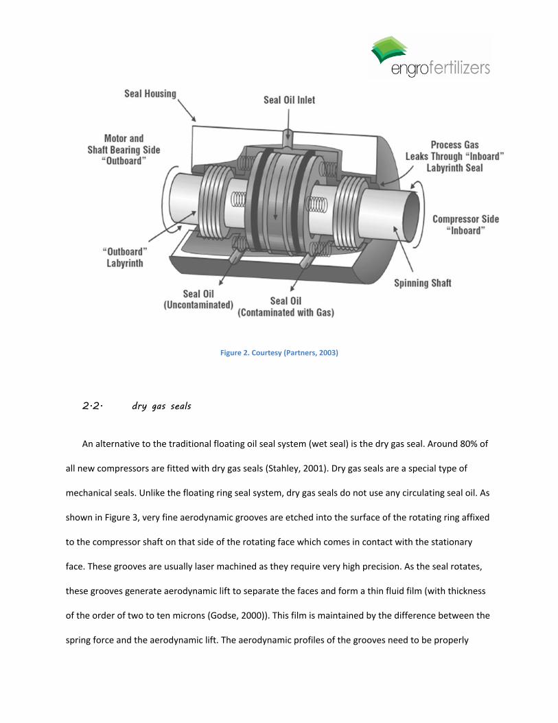
Figure 2. Courtesy (Partners, 2003)
2.2. dry gas seals
An alternative to the traditional floating oil seal system (wet seal) is the dry gas seal. Around 80% of
all new compressors are fitted with dry gas seals (Stahley, 2001). Dry gas seals are a special type of
mechanical seals. Unlike the floating ring seal system, dry gas seals do not use any circulating seal oil. As
shown in Figure 3, very fine aerodynamic grooves are etched into the surface of the rotating ring affixed
to the compressor shaft on that side of the rotating face which comes in contact with the stationary
face. These grooves are usually laser machined as they require very high precision. As the seal rotates,
these grooves generate aerodynamic lift to separate the faces and form a thin fluid film (with thickness
of the order of two to ten microns (Godse, 2000)). This film is maintained by the difference between the
spring force and the aerodynamic lift. The aerodynamic profiles of the grooves need to be properly

designed to establish equilibrium between the two forces and to allow for sudden changes in system
parameters such as pressure. The purpose of having a fluid film is to have a non-contacting seal, thus
virtually eliminating any friction between the two faces.
Figure 3
2.2.1. dry gas seal working principle
Dry seals operate mechanically under the opposing forces created by the aerodynamic grooves
and the static pressure. When the compressor is not rotating, the stationary and rotating rings are
pressed against each other by the force of the springs. When the compressor shaft starts rotating at
high speeds, the compressed gas has only one passageway to leak down the shaft, and that is from
in between the stationary and rotating rings. As the gas is pumped between the rings by grooves in
the rotating ring, the force causes the rings to separate. The opposing force of the springs causes a
very thin gap to be generated through which very little gas can leak. While the compressor is
operating, the rings do not come in contact with each other, and therefore there is no wear or need
for lubrication. O-rings act as secondary sealing devices and help seal the stationary rings in the seal
case. The forces acting on the seal varies with the gas film thickness generally as shown in Figure 4;
the equilibrium point where the two curves intersect is different for each seal (around 2 microns in
this case).

Figure 4. Courtesy (Partners, 2003)
Figure 5. Courtesy (Partners, 2003)
2.2.2. dry gas seals components
Dry gas seals have parts similar to that of a basic pusher type mechanical seal, but in this case
the rotating face has aerodynamic grooves machined on it to generate lift. These grooves can be of
many designs; spiral grooves (Figure 3) are the most common. Chevron (Figure 6(b)) or T-grooves (Figure
6(a)) are an alternative to spiral grooves when bidirectional lift is required, for example in machines
where the shaft may tend to reverse roll when stopped. Another difference is that dry gas seals have
wider seal faces.

Figure 6
2.2.3. dry gas seal configurations
Single: Only one seal is present. It may be an inside (the pump casing) seal or and outside seal.
Face-to-face: One seal inside the stuffing box and one outside. The two seals face each other.
Back-to-back: Seals have their backs to each other.
Tandem arrangement: The most common and safest type of double-seal arrangement. If one of
the seal fails then the other can take over until the first is completely repaired. A typical dry gas
seal tandem arrangement is shown in Figure 7.
Figure 7. Courtesy (Partners, 2003)

3. dry gas seals vs. floating ring (wet) seals
Generally dry gas seals significantly reduce emissions and at the same time increase efficiency and
decrease running costs. The benefits that can be attained from a properly designed and installed dry
gas seal system are:
Lower gas leakages: Both floating ring seals and dry gas seals leak almost the same amount
of gas primarily. But a lot of gas from floating ring seals is vented during the degassing
process, increasing the actual leakage by an immense amount. Dry gas seals leak at a rate of
0.5-3 scfm (Figure 8) while wet seals can leak as much as 40-200 scfm (Partners, 2003).
Less maintenance costs: Dry gas seal systems have lesser moving parts (motors, pumps,
valves etc.) and hence lower maintenance requirements.
Lower power consumption and operating costs: As dry gas systems don’t have many
auxiliary equipments as compared wet seals (oil pumps, motors etc.), the power
consumption is decreased by more than ten times.
Seal oil consumption costs: New seal oil does not need to be bought periodically; including
the cost of disposal or recovery of sour seal oil.
Elimination of process gas contamination: As there is no seal oil required, there is no leakage
of seal oil into the pipeline and eventually into the process gas.
Improvement in reliability: Dry seal systems have lesser auxiliary equipment, meaning lesser downtime
and increased reliability. The average dry gas failure rate is about only one failure every six years (Bloch,
Consider Dry Gas Seal for Centrifugal Compressors, 2005).

Figure 8. Courtesy (Partners, 2003)

The points are further supported by the table shown below (Bloch, Improving Machinery Reliability,
1998).
Table 1
Other than the advantages of dry gas seals stated above, there are also some limitations and installation
requirements to be considered when converting to dry gas seal systems from wet seal systems:

Need for machining compressor heads: The casing will most probably need to be machined in
order to provide for the gas ports.
Change in rotor dynamics: The wet seals are dampers and affect rotor dynamics. A complete
Rotor Dynamic Analysis (RDA) must be done with the dry gas seal; additional damping might be
required if results are unacceptable.
Seal susceptible to failure due to dirty gas: The process gas must be properly filtered to make it
clean and dry before being compressed.
Reduced reliability during shutdown and startup: At low speeds dry gas seals are unable to
develop the proper lift to separate the faces and maybe lead to premature failure of the seal.
This can be a problem for plants that have frequent shutdowns.
Higher cost: The initial cost of a dry gas seal is nearly twice as much as that of a floating ring seal
($50,000-$60,000 for dry gas seals as compared to $20,000-$30,000 for floating seals).
Maintenance: Spare seal cartridges have to be kept in storage in underdeveloped and
developing countries as seals will have to be sent abroad to be repaired.
Reverse rotation: For machines that have frequent reverse rotations, bidirectional (T or
Chevron) grooves are required instead of unidirectional (spiral) grooves.
Protection from bearing oil: To prevent bearing oil from leaking into the seal and reaching the
seal faces, it is necessary to use a barrier seal; this seal requires barrier gas. For safety reasons
the barrier gas must be a clean inert gas such as Nitrogen. So a nitrogen source must be
available.
4. situation at Engro Fertilizers Ltd.
The seal system in consideration in this report is the floating ring type seal system installed on the K-
2502 Syngas Compressor, located on the Ammonia-2 plant of Engro Fertilizers Ltd. According to the
records available at the Field Maintenance office, in the seven years from 2001 to 2006, the seal

system has failed multiple times, and has to be replaced; sometimes after severe vibration levels
were detected.
1) In the Turnaround of April 2001:
10th April 2001; Oil seal rings were removed and replaced later.
11th April 2001; Oil seal labyrinths were replaced.
2) In April 2005:
2nd April 2005; Inboard floating ring seal was replaced.
10th April 2005; Labyrinth seal had to be repaired using Belzona®.
16th April 2005; Inboard and Outboard bearing seals were replaced.
3) In May 2006:
20th May 2006; Inboard seal replacement. Inner diameter of rings was larger than the
original inner diameter, resulting in increased clearance.
According to a recommendation given by Dresser-Rand a few years back, if Engro Fertilizers were to
convert to dry gas seals, the investment return would be in approximately 1.47 years.
5. converting to dry gas seals
Companies usually decide to install dry gas seals under one of these three conditions: they are
replacing a whole compressor, they are replacing an exhausted seal, or they are replacing a functioning
wet seal. The third case is what best describes the case of Engro Fertilizers Ltd. Before the decision to
convert to dry gas seals can be taken, few steps must be undertaken. They are as follows,
Identify the machines for which dry gas seals are required: Engineers should make a
complete list of all the compressors on the plant. The list should include necessary
information about the compressors, such as type, hardware, age and operating
conditions. For example the compressor must be a centrifugal compressor. Also dry gas
seals can operate safely up to pressures of 3000 psi and temperatures of 400 °F (due to

O-ring material considerations). Above these conditions it might not be feasible to use
dry gas seals.
Make an estimate of the savings due to dry gas seal conversion: For compressors that
pass the previous criteria, an estimate of the savings must be calculated. Most of the
savings made will be in the form of the amount of Syngas losses reduced. Also much of
the savings come from decreased maintenance and operation costs.
Find out the cost of conversion to dry gas seals: The cost of a seal will depend on the
shaft size, operating conditions, speed and some other installation-related factors. Cost
of wet seals ranges from $6,750 and $8,100 per every inch of the shaft diameter. Dry
gas seals cost around $10,800 to $13,500 per inch of the shaft diameter for tandem
configuration. If the compressor is beam type, the costs will be doubled. The cost of
ancillary components for dry gas seals ranges from $40,500 to $135,000.
Compare the savings and the costs: A comparison of the cost vs. savings will definitely
show significant savings over a period of four to six years for any chosen compressor.
6. case history: Petrobras’ Ammonia and Urea Plant in Camaḉari, Brazil
About eleven years back the Petrobras’ plant faced a similar situation. They too had decided to
convert from floating ring oil seals to dry gas seals on their syngas compressor. The low pressure
compressor (suction: 370 psia; discharge: 927 psia) dry gas seal system faced no problems
whatsoever in the next five years of operation. The high pressure compressor (suction: 884 psia;
discharge: 2218 psia) however faced a number of problems during those years. The HP seal failed
seven times in the years 2000 to 2005. The dry gas seals were installed along with a basic dry gas

support panel. The panel comprised a basic filtration setup, a differential pressure control system
and a vent leakage monitor.
6.1. hp seal failure causes:
During startup ammonia synthesis catalyst reduction resulted in liquid water in the gas
flow; this water was the first cause of failure. Figure 9 shows the damaged mating face.
The next time the seal failed a black powder was found in the seal casing, indicating the
gas was not really properly cleaned. To remedy this problem, the HP seal gas supply was
shifted to a point ahead of the reactor pre-heater where the gas was cleaner and drier.
During startups and shutdowns the supply point had to be shifted back to the
compressor discharge, resulting in saturation of the coolers. During these transient
conditions there was not enough pressure difference between the process gas and the
seals gas. This caused dirty process gas to enter the seal’s casing.
Figure 9
6.2. hp seal failure remedy:

To fix this unacceptable rate of 1.4 failures per year, the plant decided to install a conditioning
system. This consisted of:
A wet gas dual pre-filter separator
An air driven pressure boost system (for transient conditions)
A relief valve
316 stainless steel tubes and fittings were installed
The seal hasn’t failed even once since this conditioning system was installed at the compressor.
7. conclusion
The following conclusions can be derived from the report:
If the wet seal is nearing the end of its life, it is financially more feasible to install a dry gas
seal rather than another wet seal system. Dry gas seals should be installed whenever
technically possible. In some cases early replacement of wet seals might even be a
possibility.
As 80% of all new compressors come with dry gas seals; this should be another point in
favor of conversion to dry gas seals.
Dry gas seals get rid of problems such as process gas contamination and catalyst poisoning
by seal oil, lube oil contamination with process gas and unscheduled shutdowns due to seal
oil/seal oil pump related failures.
Before installing dry gas seals, a comprehensive feasibility analysis must be done. It should
include compressor rotor dynamic analysis (RDA), seal dimensional compatibility, operating
conditions compatibility and seal gas supply source etc.
The maintenance team must be specially trained for dealing with dry gas seals.

Bibliography Bloch, H. (2005). Consider Dry Gas Seal for Centrifugal Compressors. Hydrocarbon Processing Magazine .
Bloch, H. (1998). Improving Machinery Reliability. Houston, Texas: Gulf Publishing Company.
Godse, A. G. (2000). Understand Dry Gas Seals. Hydrocarbon Processing Magazine .
Partners, N. G. (2003). Replacing Wet Seals With Dry Seals in Centrifugal Compressors. EPA - Lessons
Learned Summaries .
Stahley, J. S. (2001). Design, Operation and maintenance Consideration for Improved Dry Gas Seal
Reliability in Centrifugal Compressors. Turbomachinery Symposium .