draft recommendation y.17ethoam oam functions and ... · 3.44 in-service oam usage – in-service...
TRANSCRIPT
This document contains an updated version of draft Recommendation Y.17ethoam "OAM Functions and Mechanisms for Ethernet based Networks". This version was drafted during the plenary meeting of SG13 (Geneva, 25 April – 6 May 2005).
NOTE: Not all the sections have been updated based on the discussions, and these sections are marked with the editorial notes. These are targeted to be updated in the next version of draft Recommendation Y.17ethoam which is expected to be made available by the editor by June 30, 2005. This will be uploaded in the informal Q.5/13 ftp site: http://ties.itu.int/u/tsg13/sg13/xchange/wp4/q5/0508_Geneva/
Draft Recommendation Y.17ethoam
OAM Functions and Mechanisms for Ethernet based Networks
Summary
This Recommendation provides mechanisms for user-plane OAM functionality in Ethernet networks according to the requirements and principles given in Recommendation Y.1730. This Recommendation is designed specifically to support point-to-point connections and multipoint connectivity in the ETH layer as identified in Recommendation G.8010.
The OAM mechanisms defined in this Recommendation offer capabilities to operate and maintain the network and service aspects of ETH layer.
[Editor’s Note-May2005] If OAM mechanisms are limited in their application by connectivity type in ETH layer networks, these limitations will be reflected in Summary in the final version of the draft Recommendation.
TSB Note: All rights reserved. No part of this publication may be reproduced, by any means whatsoever, without the prior written permission of ITU.
- 2 -
1 Scope The scope of this Recommendation is to specify mechanisms required to operate and maintain the network and service aspects of ETH layer. This Recommendation also specifies the Ethernet OAM frame formats and syntax and semantics of OAM frame fields. The OAM mechanisms as described in this Recommendation apply to both point-to-point ETH connections and multipoint ETH connectivity. The OAM mechanisms as described in this Recommendation are also applicable to environments where ETH layer is managed using network management systems and/or operational support systems.
The architectural basis for this Recommendation is the Ethernet specification G.8010 which also accounts for IEEE 802.1D, 802.1Q, 802.3 and developments of IEEE P802.1ad, P802.1ah provider bridged networks. Furthermore the Connectivity Fault Management currently being defined in IEEE P802.1ag task force is taken into account.
The details of the atomic functions are not within the scope of this Recommendation which are expected to be specified in G.8021. The OAM functions of the server layer networks used by the Ethernet network are not within the scope of this Recommendation. The OAM functions of the layers above the ETH layer are also not within the scope of this Recommendation.
2 References The following ITU-T Recommendations and other references contain provisions, which, through reference in this text, constitute provisions of this Recommendation. At the time of publication, the editions indicated were valid. All Recommendations and other references are subject to revision; users of this Recommendation are therefore encouraged to investigate the possibility of applying the most recent edition of the Recommendations and other references listed below. A list of the currently valid ITU-T Recommendations is regularly published.
The reference to a document within this Recommendation does not give it, as a stand-alone document, the status of a Recommendation
[1] ITU-T Recommendation Y.1730 (2004), Requirements for OAM functions in Ethernet based networks.
[2] ITU-T Recommendation I.610 (1999), B-ISDN operation and maintenance principles and functions.
[3] CCITT Recommendation M.20 (1992), Maintenance philosophy for telecommunications network.
[4] ITU-T Recommendation G.805 (2000), Generic functional architecture of transport networks.
[5] ITU-T Recommendation G.8010 (2003), Architecture of Ethernet Layer Networks.
[6] ITU-T Recommendation G.8041 (2001), Generic Framing Procedure (GFP).
[7] MEF 10 (2004), Ethernet Services Attributes: Phase 1.
[8] ITU-T Recommendation G.809 (2003), Functional architecture of connectionless layer networks.
[9] IEEE Standard 802.1D-2004, IEEE Standard for Local and Metropolitan Area Networks: Media Access Control (MAC) Bridges.
[10] IEEE Standard 802.1Q-2003, IEEE Standards For Local And Metropolitan Area Networks: Virtual Bridged Local Area Networks.
- 3 -
[11] IEEE Standard 802.3-2002, Information Technology – Telecommunication and Information Exchange Between Systems – LAN/MAN – Specific Requirements – Part 3: Carrier Sense Multiple Access with Collision Detection (CSMA/CD) Access Method and Physical Layer Specifications.
3 Definitions This Recommendation uses terms defined in ITU-T G.805:
3.1 connection point
3.2 link
3.3 link connection
3.4 network connection
3.5 network operator
3.6 service provider
3.7 termination connection point
3.8 trail
3.9 trail termination This Recommendation uses terms defined in ITU-T G.809:
3.10 adaptation
3.11 adapted information
3.12 client/server relationship
3.13 connectionless trail
3.14 flow
3.15 flow domain
3.16 flow domain flow
3.17 flow point
3.18 flow point pool
3.19 flow point pool link
3.20 flow termination
3.21 flow termination sink
3.22 flow termination source
3.23 layer network
3.24 link flow
3.25 network
3.26 port
3.27 reference point
3.28 traffic unit
- 4 -
3.29 transport
3.30 transport entity
3.31 transport processing function
3.32 termination flow point
3.33 termination flow point pool This Recommendation uses terms defined in ITU-T M.20:
3.34 link
3.35 trail This Recommendation uses terms defined in ITU-T G.806:
3.36 defect
3.37 failure This Recommendation uses terms defined in ITU-T G.8010:
3.38 ETH trail
3.39 ETH link
3.40 Point-to-point Ethernet connection
3.41 Multipoint Ethernet connectivity
3.42 Multipoint Ethernet connection This Recommendation defines the following terms:
3.43 Out-of-service OAM usage – Out-of-service OAM usage refers to OAM actions which are carried out while the data traffic is not expected to be present.
3.44 In-service OAM usage – In-service OAM usage refers to OAM actions which are carried out while the data traffic is present with an expectation that data traffic remains transparent to OAM actions.
3.45 Others (to be added)
[Editor’s Note-May2005] Definitions to be completed
4 Abbreviations This Recommendation uses the following abbreviations: AP Access Point CE Customer Edge CP Connection Point DoS Denial of Service ETH Ethernet MAC layer network ETH-AIS Ethernet Alarm Indication Signal ETH-CC Ethernet Continuity Check ETH-DM Ethernet Delay Measurement ETH-LB Ethernet Loopback
- 5 -
ETH-LM Ethernet Loss Measurement ETH-LT Ethernet Link Trace ETH-RDI Ethernet Reverse Defect Indication ETHS ETH Segment ETY Ethernet PHY layer network ETYn Ethernet PHY layer network of order n FD Flow Domain FDF Flow Domain Flow FDFr Flow Domain Fragment FP Flow Point FPP Flow Point Pool FT Flow Termination MAC Media Access Control ME Maintenance Entity MEG ME Group MEP MEG End Point MIP MEG Intermediate Point NMS Network Management System NNI Network Node Interface OAM Operation, Administration and Maintenance OTN Optical Transport Network PE Provider Edge PHY Ethernet Physical Layer entity consisting of the PCS, the PMA, and, if present, the
PMD sub layers SLA Service Level Agreement TC Traffic Conditioning TCP Traffic Conditioning Point TFP Termination Flow Point TFPP Termination Flow Point Pool UNI User Network Interface UNI-C Customer side of UNI UNI-N Network side of UNI VID VLAN Identifier VLAN Virtual LAN
5 Conventions The diagrammatic conventions for connection-oriented and connectionless layer networks described in this Recommendation are that of Recommendation G.805 [4], G.809 [8], and G.8010 [5].
- 6 -
[Editor’s Note-May2005] Reference to G.8010v2 will be added when it defines some of the following OAM terms. For the purposes of this Recommendation, the following OAM terms and diagrammatic conventions are also defined.
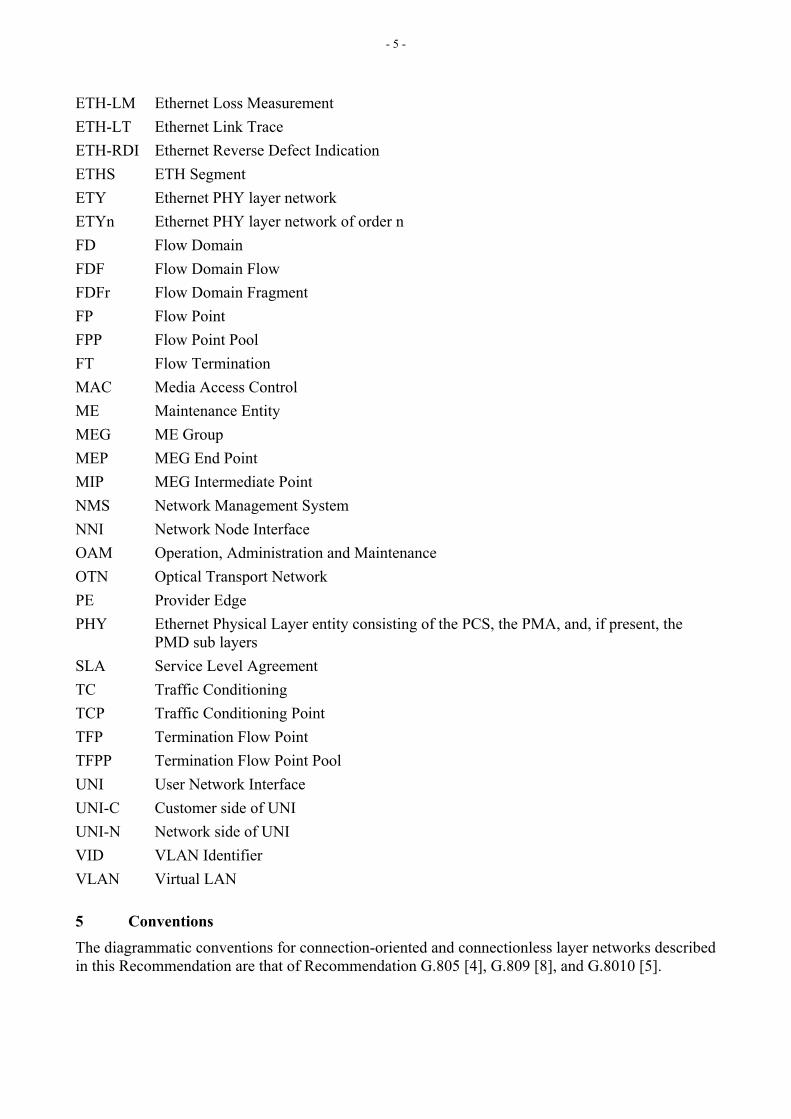
5.1 Maintenance Entity (ME) ME represents an entity that requires management and is a relationship between two Maintenance Entity Group End Points. MEs in Ethernet networks are identified in Figures 23 and 24 of G.8010 [5], as shown in Figure 5-0 and in section 9 of Y.1730 [1]. MEs can nest but not overlap.
Figure 5-0/Y.17ethoam: Figure 23/G.8010/Y.1306 Point-to-Point ETH connection administrative domain associated MEs
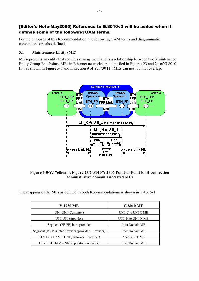
The mapping of the MEs as defined in both Recommendations is shown in Table 5-1.
Y.1730 ME G.8010 ME UNI-UNI (Customer) UNI_C to UNI-C ME UNI-UNI (provider) UNI_N to UNI_N ME
Segment (PE-PE) intra-provider Intra Domain ME Segment (PE-PE) inter-provider (provider – provider) Inter Domain ME
ETY Link OAM – UNI (customer – provider) Access Link ME ETY Link OAM – NNI (operator – operator) Inter Domain ME
- 7 -
Table 5-1/Y.17ethoam: MEs as defined in G.8010 and Y.17ethoam
5.2 ME Group (MEG) ME Group (MEG) includes different MEs that satisfy the following conditions:
1. MEs in a MEG exist in the same administrative boundary; and
2. MEs in a MEG have the same ME Level (Section 5.6), and
3. MEs in a MEG belong to the same point-to-point ETH connection or multipoint ETH connectivity.
For a point-to-point ETH connection, a MEG contains a single ME. For a multipoint ETH connectivity containing n end-points, a MEG contains n*(n-1)/2 MEs.
Note: MEG is similar to a Maintenance Association (MA) as currently defined in IEEE P802.1ag draft3.
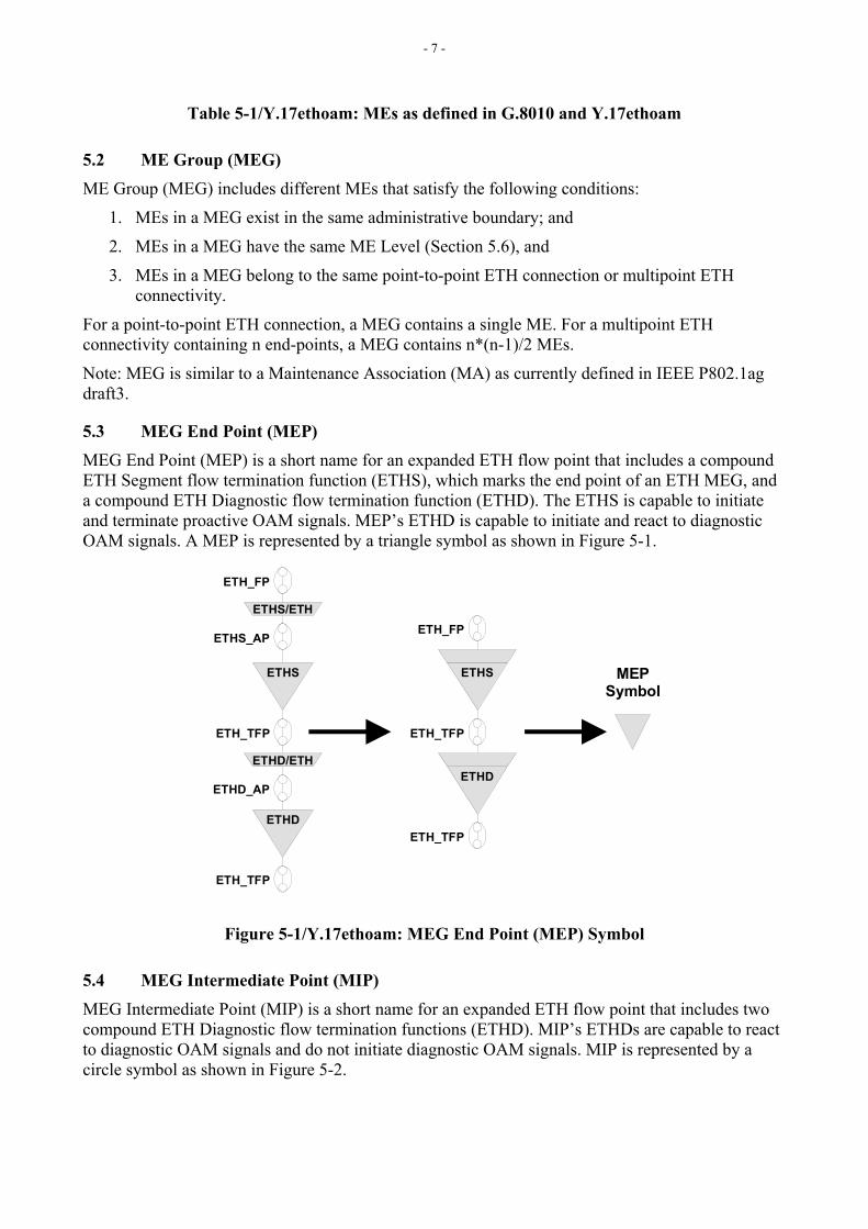
5.3 MEG End Point (MEP) MEG End Point (MEP) is a short name for an expanded ETH flow point that includes a compound ETH Segment flow termination function (ETHS), which marks the end point of an ETH MEG, and a compound ETH Diagnostic flow termination function (ETHD). The ETHS is capable to initiate and terminate proactive OAM signals. MEP’s ETHD is capable to initiate and react to diagnostic OAM signals. A MEP is represented by a triangle symbol as shown in Figure 5-1.
ETHS
ETHS/ETH
ETHD
ETHD/ETH
ETH_FP
ETHS_AP
ETH_TFP
ETHD_AP
ETH_TFP
ETHS
ETHD
MEPSymbol
ETH_FP
ETH_TFP
ETH_TFP
Figure 5-1/Y.17ethoam: MEG End Point (MEP) Symbol
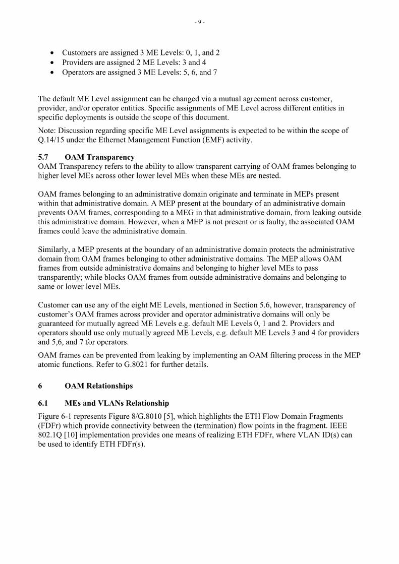
5.4 MEG Intermediate Point (MIP) MEG Intermediate Point (MIP) is a short name for an expanded ETH flow point that includes two compound ETH Diagnostic flow termination functions (ETHD). MIP’s ETHDs are capable to react to diagnostic OAM signals and do not initiate diagnostic OAM signals. MIP is represented by a circle symbol as shown in Figure 5-2.

- 8 -
ETHD
ETHD/ETH
ETHD
ETHD/ETH
ETH_TFP
ETHD_AP
ETH_FP
ETHD_AP
ETH_TFP
ETHD
ETHD
MIPSymbol
ETH_TFP
ETH_FP
ETH_TFP
Figure 5-2/Y.17ethoam: MEG Intermediate Point (MIP) Symbol
5.5 Traffic Conditioning Point (TCP) Traffic Conditioning Point (TCP) is a short name for an expanded ETH flow point that includes an ETH traffic conditioning function, as specified in Recommendation G.8010 [5]. A TCP is represented by a diamond symbol as shown in Figure 5-3.
Figure 5-3/Y.17ethoam: Traffic Conditioning Point (TCP) Symbol
5.6 ME Level At any point in a network, ME Level is used to distinguish between OAM frames belonging to different nested MEs. Eight ME Levels are available to accommodate different network deployment scenarios. The eight ME Levels are mutually agreed amongst customer, provider and operator entities involved in ETH connections. Note: When multicast DA is in OAM frames, the ME Level can be associated with the multicast DA. For further discussion on this aspect, please refer to Appendix VII. Default ME Levels assignment amongst customer, provider, and operator entities are defined in the following manner:
- 9 -
• Customers are assigned 3 ME Levels: 0, 1, and 2 • Providers are assigned 2 ME Levels: 3 and 4 • Operators are assigned 3 ME Levels: 5, 6, and 7
The default ME Level assignment can be changed via a mutual agreement across customer, provider, and/or operator entities. Specific assignments of ME Level across different entities in specific deployments is outside the scope of this document.
Note: Discussion regarding specific ME Level assignments is expected to be within the scope of Q.14/15 under the Ethernet Management Function (EMF) activity.
5.7 OAM Transparency OAM Transparency refers to the ability to allow transparent carrying of OAM frames belonging to higher level MEs across other lower level MEs when these MEs are nested. OAM frames belonging to an administrative domain originate and terminate in MEPs present within that administrative domain. A MEP present at the boundary of an administrative domain prevents OAM frames, corresponding to a MEG in that administrative domain, from leaking outside this administrative domain. However, when a MEP is not present or is faulty, the associated OAM frames could leave the administrative domain. Similarly, a MEP presents at the boundary of an administrative domain protects the administrative domain from OAM frames belonging to other administrative domains. The MEP allows OAM frames from outside administrative domains and belonging to higher level MEs to pass transparently; while blocks OAM frames from outside administrative domains and belonging to same or lower level MEs. Customer can use any of the eight ME Levels, mentioned in Section 5.6, however, transparency of customer’s OAM frames across provider and operator administrative domains will only be guaranteed for mutually agreed ME Levels e.g. default ME Levels 0, 1 and 2. Providers and operators should use only mutually agreed ME Levels, e.g. default ME Levels 3 and 4 for providers and 5,6, and 7 for operators.
OAM frames can be prevented from leaking by implementing an OAM filtering process in the MEP atomic functions. Refer to G.8021 for further details.
6 OAM Relationships
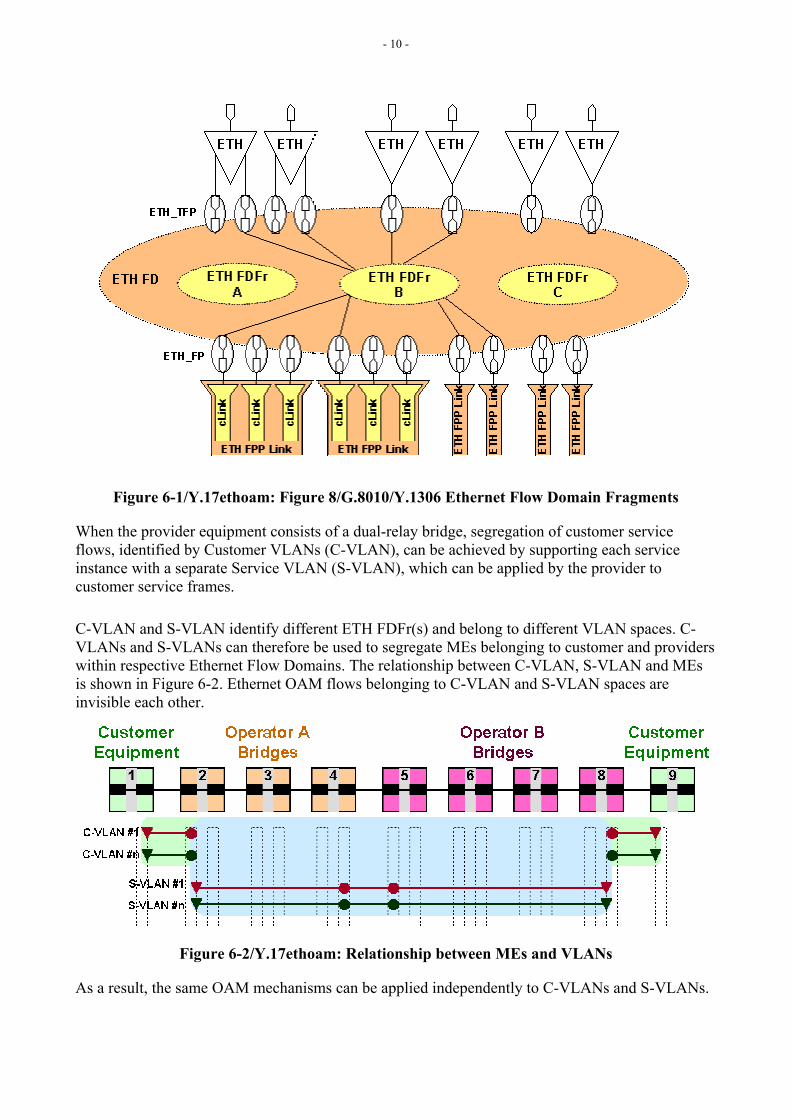
6.1 MEs and VLANs Relationship Figure 6-1 represents Figure 8/G.8010 [5], which highlights the ETH Flow Domain Fragments (FDFr) which provide connectivity between the (termination) flow points in the fragment. IEEE 802.1Q [10] implementation provides one means of realizing ETH FDFr, where VLAN ID(s) can be used to identify ETH FDFr(s).
- 10 -
Figure 6-1/Y.17ethoam: Figure 8/G.8010/Y.1306 Ethernet Flow Domain Fragments
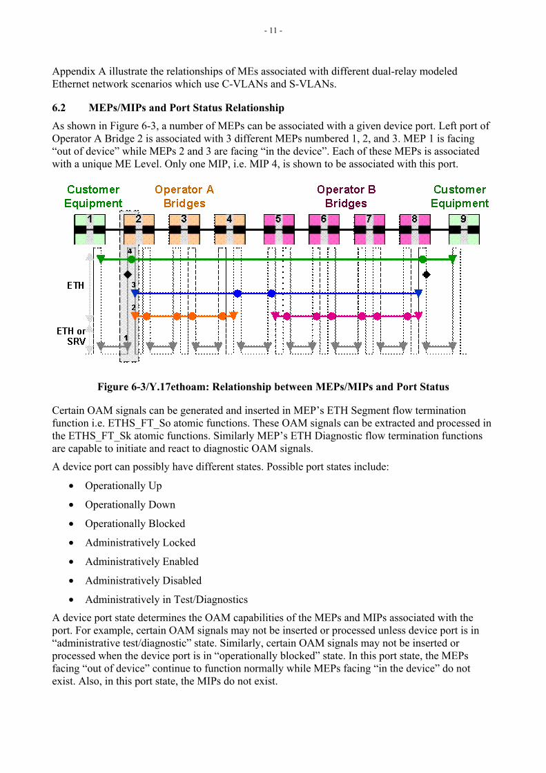
When the provider equipment consists of a dual-relay bridge, segregation of customer service flows, identified by Customer VLANs (C-VLAN), can be achieved by supporting each service instance with a separate Service VLAN (S-VLAN), which can be applied by the provider to customer service frames.
C-VLAN and S-VLAN identify different ETH FDFr(s) and belong to different VLAN spaces. C-VLANs and S-VLANs can therefore be used to segregate MEs belonging to customer and providers within respective Ethernet Flow Domains. The relationship between C-VLAN, S-VLAN and MEs is shown in Figure 6-2. Ethernet OAM flows belonging to C-VLAN and S-VLAN spaces are invisible each other.
Figure 6-2/Y.17ethoam: Relationship between MEs and VLANs
As a result, the same OAM mechanisms can be applied independently to C-VLANs and S-VLANs.
- 11 -
Appendix A illustrate the relationships of MEs associated with different dual-relay modeled Ethernet network scenarios which use C-VLANs and S-VLANs.
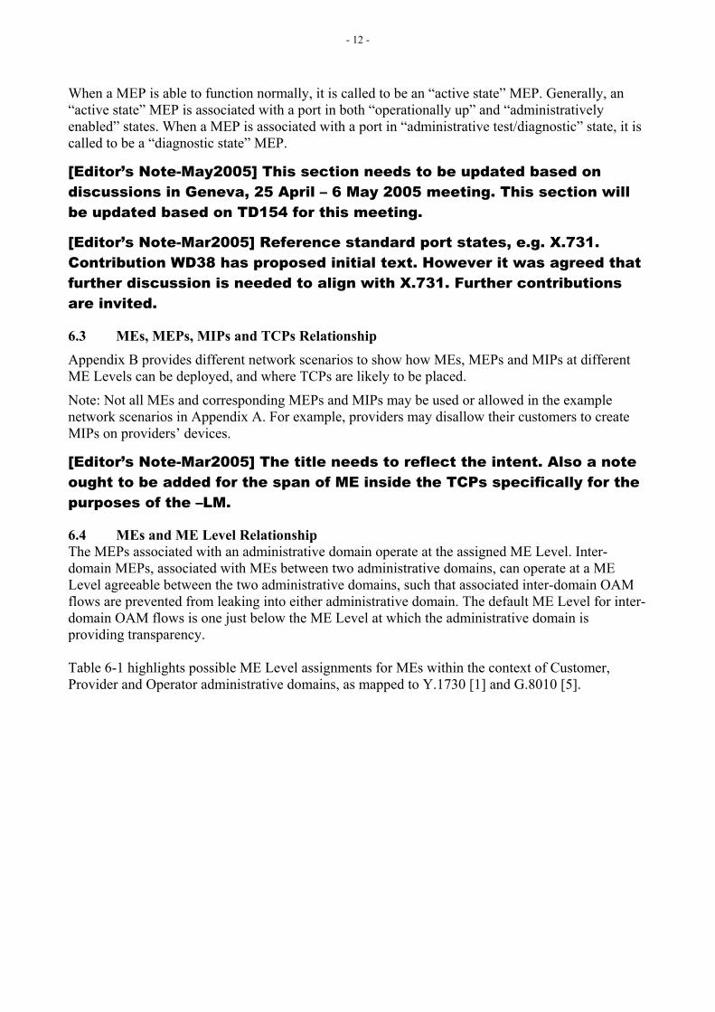
6.2 MEPs/MIPs and Port Status Relationship As shown in Figure 6-3, a number of MEPs can be associated with a given device port. Left port of Operator A Bridge 2 is associated with 3 different MEPs numbered 1, 2, and 3. MEP 1 is facing “out of device” while MEPs 2 and 3 are facing “in the device”. Each of these MEPs is associated with a unique ME Level. Only one MIP, i.e. MIP 4, is shown to be associated with this port.
Figure 6-3/Y.17ethoam: Relationship between MEPs/MIPs and Port Status
Certain OAM signals can be generated and inserted in MEP’s ETH Segment flow termination function i.e. ETHS_FT_So atomic functions. These OAM signals can be extracted and processed in the ETHS_FT_Sk atomic functions. Similarly MEP’s ETH Diagnostic flow termination functions are capable to initiate and react to diagnostic OAM signals.
A device port can possibly have different states. Possible port states include:
• Operationally Up
• Operationally Down
• Operationally Blocked
• Administratively Locked
• Administratively Enabled
• Administratively Disabled
• Administratively in Test/Diagnostics
A device port state determines the OAM capabilities of the MEPs and MIPs associated with the port. For example, certain OAM signals may not be inserted or processed unless device port is in “administrative test/diagnostic” state. Similarly, certain OAM signals may not be inserted or processed when the device port is in “operationally blocked” state. In this port state, the MEPs facing “out of device” continue to function normally while MEPs facing “in the device” do not exist. Also, in this port state, the MIPs do not exist.
- 12 -
When a MEP is able to function normally, it is called to be an “active state” MEP. Generally, an “active state” MEP is associated with a port in both “operationally up” and “administratively enabled” states. When a MEP is associated with a port in “administrative test/diagnostic” state, it is called to be a “diagnostic state” MEP.
[Editor’s Note-May2005] This section needs to be updated based on discussions in Geneva, 25 April – 6 May 2005 meeting. This section will be updated based on TD154 for this meeting.
[Editor’s Note-Mar2005] Reference standard port states, e.g. X.731. Contribution WD38 has proposed initial text. However it was agreed that further discussion is needed to align with X.731. Further contributions are invited.
6.3 MEs, MEPs, MIPs and TCPs Relationship Appendix B provides different network scenarios to show how MEs, MEPs and MIPs at different ME Levels can be deployed, and where TCPs are likely to be placed.
Note: Not all MEs and corresponding MEPs and MIPs may be used or allowed in the example network scenarios in Appendix A. For example, providers may disallow their customers to create MIPs on providers’ devices.
[Editor’s Note-Mar2005] The title needs to reflect the intent. Also a note ought to be added for the span of ME inside the TCPs specifically for the purposes of the –LM.
6.4 MEs and ME Level Relationship The MEPs associated with an administrative domain operate at the assigned ME Level. Inter-domain MEPs, associated with MEs between two administrative domains, can operate at a ME Level agreeable between the two administrative domains, such that associated inter-domain OAM flows are prevented from leaking into either administrative domain. The default ME Level for inter-domain OAM flows is one just below the ME Level at which the administrative domain is providing transparency. Table 6-1 highlights possible ME Level assignments for MEs within the context of Customer, Provider and Operator administrative domains, as mapped to Y.1730 [1] and G.8010 [5].
- 13 -
Y.1730 ME G.8010 ME ME Level UNI-UNI (Customer) UNI_C to UNI-C ME 0,1, or 2 UNI-UNI (provider) UNI_N to UNI_N ME 3, or 4
Segment (PE-PE) intra-provider Intra Domain ME 3, or 4 Segment (PE-PE) inter-provider (provider – provider) Inter Domain ME 7 (default)
ETY Link OAM – UNI (customer – provider) Access Link ME 7 (default) ETY Link OAM – NNI (operator – operator) Inter Domain ME 7 (default)
Table 6-1/Y.17ethoam: MEs and ME Level Relationship
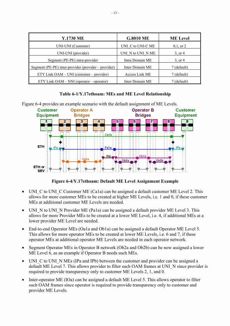
Figure 6-4 provides an example scenario with the default assignment of ME Levels.
Figure 6-4/Y.17ethoam: Default ME Level Assignment Example
• UNI_C to UNI_C Customer ME (Ca1a) can be assigned a default customer ME Level 2. This allows for more customer MEs to be created at higher ME Levels, i.e. 1 and 0, if these customer MEs at additional customer ME Levels are needed.
• UNI_N to UNI_N Provider ME (Pa1a) can be assigned a default provider ME Level 3. This allows for more Provider MEs to be created at a lower ME Level, i.e. 4, if additional MEs at a lower provider ME Level are needed.
• End-to-end Operator MEs (Oa1a and Ob1a) can be assigned a default Operator ME Level 5. This allows for more operator MEs to be created at lower ME Levels, i.e. 6 and 7, if these operator MEs at additional operator ME Levels are needed in each operator network.
• Segment Operator MEs in Operator B network (Ob2a and Ob2b) can be now assigned a lower ME Level 6, as an example if Operator B needs such MEs.
• UNI_C to UNI_N MEs (IPa and IPb) between the customer and provider can be assigned a default ME Level 7. This allows provider to filter such OAM frames at UNI_N since provider is required to provide transparency only to customer ME Levels 2, 1, and 0.
• Inter-operator ME (IOa) can be assigned a default ME Level 5. This allows operator to filter such OAM frames since operator is required to provide transparency only to customer and provider ME Levels.
- 14 -
6.5 MEPs and MIPs Configurations MEPs and MIPs can be configured along with their ME Levels either manually or automatically. Manual configurations may be performed either through manual local administration of each device or via Network Management Systems (NMS) as indicated in operational scenarios in Appendix B. Automatic configurations are also possible via control plane mechanisms and data plane mechanisms using OAM signals. Automatic configurations of MEPs and MIPs are outside the scope of this Recommendation.
7 OAM Functions for Fault Management OAM functions allow detection of different defects. Appendix xx2 provides an overview of these different defects. Defects will be covered in detail in Recommendation G.8021v2.
7.1 Ethernet Continuity Check (ETH-CC) Ethernet Continuity Check (ETH-CC) function can be used to detect loss of continuity defects (dLOC) between a pair of MEPs. ETH-CC function also allows detection of mismerge defects (dMismerge) and unexpected defects (dUnexpected).
When a MEP is enabled to generate and insert ETH-CC frames, it periodically sends ETH-CC frames to all other MEPs in the same MEG. ETH-CC transmission rate is expected to be the same for all MEPs in a MEG. When a MEP is enabled to process ETH-CC frames, it expects to receive ETH-CC frames from its peer MEPs in the same MEG.
Specific information required by each MEP to support ETH-CC is the following:
• MEG ID – to identify the MEG to which the MEP belongs
• MEP ID – MEP’s own identified in the MEG
• List of peer MEP IDs – list of peer MEPs in the same MEG. For a point-to-point MEG with a single ME, the list would consist of a single MEP ID for the peer.
• ME Level – ME Level at which the MEP exists
• ETH-CC transmission rate – this is application dependent. As noted earlier, the transmission rate is expected to be the same for all MEPs in a MEG. It is expected that ETH-CC would have 3 different applications (for each application, a default transmission rate would be specified):
o Fault Management
o Protection Switching
o Error Performance Management
• Priority – it identified the priority of the ETH-CC frames. By default, the ETH-CC frames can be transmitted with the highest priority available to the data frames of the ETH-CC user. Otherwise, the priority can be configured.
• Discard Eligibility – ETH-CC frames are always marked as discard ineligible.
A MIP is transparent to the ETH-CC frames and therefore does not require any information to support ETH-CC functionality.
When a MEP does not receive ETH-CC frames from a peer MEP, in the list of peer MEPs, within an interval of 3.5 times the ETH-CC transmission rate, it detects loss of continuity defect (dLOC) to that peer MEP. The interval corresponds to a loss of 3 consecutive ETH-CC frames from the peer MEP.
- 15 -
When a MEP receives an ETH-CC frame with an incorrect MEG ID, it declares a mismerge defect (dMismerge). When a MEP receives an ETH-CC frame with correct MEG ID but an unexpected MEP ID, it declares an unexpected defect (dUnexpected).
Consequent actions taken upon the detection of these defects are outside the scope of this Recommendation. These consequent actions will be covered in Recommendation G.8021v2.
[Editor’s Note-May2005] Contributions are invited to propose default values for ETH-CC transmission rate for the identified application areas.
[Editor’s Note-May2005] Use of Lifetime in ETH-CC facilitates (a) detection of ETH-CC transmission rate mismatch between a pair of MEPs, and (b) adaptation of dLOC defect detection interval at receiver MEP. Need for both these features needs to be determined.
7.1.1 ETH-CC Operations
7.1.1.1 ETH-CC Transmission Every “active state” MEP can transmit an ETH-CC frame as often as the configured transmission rate. Configured transmission rate may range from 0.01 seconds to 655.35 seconds. Recommendation for ETH-CC transmission rates for the three application areas identified above is FFS.
When Lifetime field is used, it is transmitted with a value of 3.5 times the configured transmission rate, so that a receiving MEP can lose two ETH-CC frames without declaring a dLOC defect. A Lifetime value can range from 1 to 65535 where value 1 corresponds to .035 seconds and value 65535 corresponds to 2293.725 seconds. The need for Lifetime field is FFS.
7.1.1.2 ETH-CC Reception Every “active state” MEP that receives an ETH-CC frame, examines it to ensure that its MEG ID matches with the configured MEG ID in the receiving MEP, and that the MEP ID in the ETH-CC frame is one from the configured list of peer MEP IDs. The information in the ETH-CC frame is catalogued in the receiving MEP, indexed by the received MEP ID. Information saved includes the the source MAC address and data path service identifier (e.g. VLAN) of the received ETH-CC frame, the Bridge Port on which it was received, and Lifetime field value, if used, so that the information can be timed out (if the value of Lifetime is 0, the catalogued information for the received MEP ID, if any, is discarded).
When an ETH-CC frame is received at a MEP, the source MAC address, data path service identifier, ME Level, and ingress Bridge Port are recorded, indexed by MAC address, data path service identifier and ME Level, in the Provider Bridge’s ETH-CC Database.
If no ETH-CC frames from a peer MEP are received within the interval associated with 3.5 times the peer MEP’s ETH-CC transmission rate, dLOC defect with peer MEP is declared.
If an ETH-CC frame with incorrect MEG ID is received, dMismerge defect is declared.
If an ETH-CC frame with correct MEG ID but incorrect MEP ID, including receiving MEP’s own MEP ID, is received, dUnexpected defect is declared.
7.2 Ethernet Loopback (ETH-LB) Ethernet Loopback (ETH-LB) function can be used to verify connectivity of a MEP with a MIP or its peer MEP(s). ETH-LB can be of two types:
- 16 -
• Unicast ETH-LB
• Multicast ETH-LB
7.2.1 Unicast ETH-LB Unicast ETH-LB function is used to verify bidirectional connectivity of a MEP with a MIP or a peer MEP. Unicast ETH-LB can be used either on an on-demand basis (e.g. via an operator initiated command) or periodic basis. For periodic usage, when the periodic rate is slower compared to the data traffic, Unicast ETH-LB is suitable for periodic in-service connectivity verification. However, for periodic usage, when the periodic rate is full rate (i.e. as the data traffic), Unicast ETH-LB is suitable for out-of-service testing (see Section 7.xx).
When a MEP is required to send Unicast ETH-LB to a remote MIP or MEP (the MIP or MEP is identified with a specific address (i.e. Unicast MAC DA), it sends Unicast ETH-LB request frame and expects to receive a Unicast ETH-LB reply frame from the remote MIP or MEP within a specified time-period. If the MEP does not receive the Unicast ETH-LB reply frame with the specified time-period, the loss of connectivity with the remote MIP or MEP is detected.
Specific information required by each MEP to support Unicast ETH-LB function is the following:
• ME Level – ME Level at which the MEP exists
• Priority – it identified the priority of the Unicast ETH-LB frames over the data frames.
• Discard Eligibility – it identified the eligibility of Unicast ETH-LB frames to be discarded when congestion conditions are encountered.
• Periodicity – when Unicast ETH-LB is used on a periodic basis. The periodicity is configurable.
• Unicast MAC address of remote MIP or MEP to which ETH-LB is intended.
A remote MIP or MEP, upon receiving the Unicast ETH-LB request frame which is addressed to the remote MIP or MEP, responds with a Unicast ETH-LB reply frame if the request frame arrives with the same ME Level as the remote MIP’s or MEP’s ME Level. A MEP is already required to have the ME Level information to support Unicast ETH-LB function, as described above.
Specific information required by a MIP to support Unicast ETH-LB function is the following:
• ME Level – ME Level at which the MIP exists
[Editor’s Note-May2005] It is currently assumed that while processing a Unicast ETH-LB request frame, the receiving MIP or MEP does not validate it for dMismerge (mis-merge) condition i.e. does not check the MEG ID. The implication is that if some validation is needed to check for MEG ID, the diagnostic function of MIP would require extra processing. Question to Q.14/15, Q.9/15 – Are there any potential security issues/concerns?
7.2.1.1 Unicast ETH-LB Operations
7.2.1.1.1 Unicast ETH-LB Request Transmission
Unicast ETH-LB request frame can be transmitted by a MEP either automatically (either periodically) or by an operator initiated command (EMS/NMS management interfaces, e.g. SNMP). After transmitting the Unicast ETH-LB request frame with a specific Transaction Identifier, the
- 17 -
MEP expects to receive a Unicast ETH-LB reply frame within 2 seconds. The transmitted Transaction Identifier is therefore retained for at least 2 seconds after the Unicast ETH-LB request frame is transmitted. A different Transaction Identifier must be used for every Unicast ETH-LB request frame, and no Transaction Identifier from the same MEP may be repeated within one minute.
7.2.1.1.2 Unicast ETH-LB Request Reception and ETH-LB Reply Transmission Whenever a valid Unicast ETH-LB request frame is received by a MIP or MEP, a Unicast ETH-LB reply frame is generated and transmitted to the requesting MEP. Every field in the Unicast ETH-LB request frame is copied to the Unicast ETH-LB reply frame with the following exceptions:
• The source and destination MAC addresses are swapped.
• The OpCode field is changed from ETH-LB Request to ETH-LB Reply.
7.2.1.1.3 Unicast ETH-LB Reply Reception When a Unicast ETH-LB reply frame is received by a MEP with an expected Transaction Identifier and within 2 seconds of transmitting the Unicast ETH-LB request frame, the Unicast ETH-LB reply frame is valid. If a MEP receives a Unicast ETH-LB reply frame with a Transaction Identifier that is not in the list of transmitted Transaction Identifiers maintained by the MEP, the Unicast ETH-LB reply frame is invalid. When a MIP receives a Unicast ETH-LB reply frame, the Unicast ETH-LB reply frame is invalid.
7.2.2 Multicast ETH-LB Multicast ETH-LB function is used to verify bidirectional connectivity of a MEP to its peer MEPs. Multicast ETH-LB can be used purely on an on-demand basis. When Multicast ETH-LB function is used, it returns a list of its peer MEPs with whom the bidirectional connectivity has been detected. Multicast ETH-LB is intended for out-of-service diagnostics.
When a MEP is required to send Multicast ETH-LB, a Multicast ETH-LB request frame is sent from a MEP to all other MEPs in the same MEG. The MEP expects to receive Unicast ETH-LB reply frames from its peer MEPs within a specified time-period. Upon reception of this request frame, the receiving MEPs validate the Multicast ETH-LB request frame and transmit a Unicast ETH-LB reply frame after a randomized delay. If the Multicast ETH-LB request frame is found to be invalid, a receiving MEP still replies however it also raises an alert (or event).
Specific information required by each MEP to support Multicast ETH-LB function is the following:
• MEG ID – to identify the MEG to which the MEP belongs
• ME Level – ME Level at which the MEP exists
• Priority – it identified the priority of the Multicast ETH-LB frames over the data frames.
• Discard Eligibility – it identified the eligibility of Multicast ETH-LB frames to be discarded when congestion conditions are encountered.
A MIP is transparent to the Multicast ETH-LB request frames and therefore does not require any information to support Multicast ETH-LB functionality.
[Editor’s Note-May2005] It is indicated that since a single request can result in many responses, the use of Multicast ETH-LB should be limited to out-of-service diagnostics. Q.9/15 – Is there a way to associate the
- 18 -
support of this function based on a MEP state which is associated with e.g. administrative diagnostics etc?
7.2.2.1 Multicast ETH-LB Operations
7.2.2.1.1 Multicast ETH-LB Request Transmission Multicast ETH-LB request frame can be transmitted by a MEP by an operator initiated command (EMS/NMS management interfaces, e.g. SNMP). After transmitting the Multicast ETH-LB request frame with a specific Transaction Identifier, the MEP expects to receive Unicast ETH-LB reply frames within 5 seconds. The transmitted Transaction Identifier is therefore retained for at least 5 seconds after the Multicast ETH-LB request frame is transmitted. A different Transaction Identifier must be used for every Multicast ETH-LB request frame, and no Transaction Identifier from the same MEP may be repeated within one minute.
7.2.2.1.2 Multicast ETH-LB Request Reception and Unicast ETH-LB Reply Transmission Whenever a valid Multicast ETH-LB request frame is received by a MEP, a Unicast ETH-LB reply frame is generated and transmitted to the requesting MEP following a randomized delay in the range of 0-1 seconds. The validity of the Multicast ETH-LB request frame is determined based on valid MEG ID and correct ME Level. If an invalid request frame is received, the receiving MEP still replies. However, in this case, an alert (or event) is also raised. Every field in the Multicast ETH-LB request frame is copied to the Unicast ETH-LB reply frame with the following exceptions:
• Source MAC address in Unicast ETH-LB reply frame is the unicast MAC address of the replying MEP. Destination MAC address in Unicast ETH-LB reply frame is copied from the source MAC address of the Multicast ETH-LB request frame, which should be a Unicast address.
• The OpCode field is changed from ETH-LB Request to ETH-LB Reply.
• The MEP ID in the reply frame is replying MEP’s MEP ID.
7.2.2.1.3 Unicast ETH-LB Reply Reception When a Unicast ETH-LB reply frame is received by a MEP with an expected Transaction Identifier and within 5 seconds of transmitting the Multicast ETH-LB request frame, the Unicast ETH-LB reply frame is valid. If a MEP receives a Unicast ETH-LB reply frame with a Transaction Identifier that is not in the list of transmitted Transaction Identifiers maintained by the MEP, the Unicast ETH-LB reply frame is invalid. When a MIP receives a Unicast ETH-LB reply frame, the Unicast ETH-LB reply frame is invalid.
7.3 Ethernet Link Trace (ETH-LT) Ethernet Link Trace (ETH-LT) function can be used for the following two purposes:
• Adjacent Relation Retrieval – ETH-LT function can be used to identify adjacency relationship retrieval between a MEP and a remote MEP or MIP. For the purposes of establishing adjacency relationships, the sequence of MIPs and/or MEP along with their identifiers is required. A MIP is identified by its MAC addresses while a MEP is identified by its MEP ID.
• Fault Localization - ETH-LT function can be used for fault localization. When a fault (eg. a link and/or a device failure) or a forwarding plane loop occurs, the sequence of MIPs and/or MEP will likely be different from the expected one. Differences in the sequences provide information of the fault location.
- 19 -
Only a MEP is allowed to send ETH-LT request frame. After transmitting an ETH-LT request frame, the MEP expects to receive ETH-LT reply frames within a specified time-period. The receiving MIPs and MEPs selectively respond to an ETH-LT request frame. The condition for responding besides validating the request is that the receiving MIP or MEP should have knowledge about the target MAC address, which is identified via a target MAC address field in the ETH-LT request frame. When a receiving MIP has knowledge about the target MAC address, it forwards the ETH-LT request frame towards the target MAC address, and sends an ETH-LT reply frame back to the requesting MEP after some randomized delay. A receiving MEP sends an ETH-LT reply frame after some randomized delay only when the target MAC address in ETH-LT request frame is receiving MEP’s own MAC address and a receiving MEP does not forward the ETH-LT request frame any further. The receiving MIP or MEP needs to validate an ETH-LT request frame to ensure that it arrives from within a valid MEG ID at a valid ME Level. The validation is required since an ETH-LT identifies adjacency relationships which may need to be confined within a MEG.
Specific information required by each MEP to support ETH-LT function is the following:
• MEG ID – to identify the MEG to which the MEP belongs
• ME Level – ME Level at which the MEP exists
• Priority – it identified the priority of the ETH-LT frames over the data frames.
• Discard Eligibility – it identified the eligibility of ETH-LT frames to be discarded when congestion conditions are encountered.
• Target MAC address of MIP or MEP to which ETH-LT is intended
Specific information required by a MIP to support Unicast ETH-LB function is the following:
• MEG ID – to identify the MEG to which the MIP belongs
• ME Level – ME Level at which the MIP exists
[Editor’s Note-May2005] It has been assumed that a MIP is identified using its MAC address. Question.14/15, TMF, SG4 – Is a MAC address acceptable as an identifier for a MIP or a logical identifier desirable for a MIP? I.e. Is a MIP ID (different from MIP’s MAC address) needed for management purposes?
7.3.1 ETH-LT Operations
7.3.1.1 ETH-LT Request Transmission ETH-LT request frame can be transmitted by a MEP either automatically (either periodic) or by operator initiated command (EMS/NMS management interfaces e.g. SNMP). After transmitting the ETH-LT request frame with a specific Transaction Identifier, the MEP expects to receive ETH-LT reply frames within 5 seconds. The Transaction Identifier of each ETH-LT request frame transmitted is therefore retained for at least 5 seconds after the ETH-LT frame is transmitted. . A different Transaction Identifier must be used for every ETH-LT request frame, and no Transaction Identifier from the same MEP may be repeated within one minute.
7.3.1.2 ETH-LT Request Reception, Forwarding, and ETH-LT Reply Transmission If an ETH-LT request frame is received by a MEP or MIP, and if data frames addressed to same address as Target MAC address field in ETH-LT request frame would pass through the receiving MEP or MIP, the receiving MIP or MEP should:
- 20 -
• Validate ETH-LT request frame’s MEG ID and ME Level. If invalid request frame, discard ETH-LT request frame.
• Check ETH-LT request frame’s TTL field value. If TTL field value is 0, discard ETH-LT request frame (TTL field value of 0 is invalid value).
• Determine the destination address for ETH-LT reply frame from Source Address field of received ETH-LT request frame.
• If a data frame addressed to the same address as Target MAC address field in ETH-LT request frame would pass through the MEP or MIP and out a single egress device port, and if ETH-LT request frame’s’s TTL field value is greater than 1 when received, then ETH-LT request frame must be relayed on the selected egress port. If the ETH-LT request frame’s TTL field value equals 1 when received, the ETH-LT request frame is not relayed anymore. All fields are transmitted exactly as received, except for the source MAC address and TTL field value which is decremented by 1.
• After a random time interval in the range 0-1 second, transmit an ETH-LT reply frame to the originating MEP.
If a data frame addressed to the same address as Target MAC address field in ETH-LT request frame would not pass through the receiving MEP or MIP, then a receiving MIP must pass the ETH-LT request frame through as normal data while a MEP must terminate the ETH-LT request frame.
7.3.1.3 ETH-LT Reply Reception When an ETH-LT reply frame is received by a MEP with an expected Transaction Identifier and within 5 seconds of transmitting the ETH-LT request frame, the ETH-LT reply frame is valid. If a MEP receives an ETH-LT reply frame with a Transaction Identifier that is not in the list of transmitted Transaction Identifiers maintained by the MEP, the ETH-LT reply frame is invalid. When a MIP receives a ETH-LT reply frame, the ETH-LT reply frame is invalid.
7.4 ETH-AIS
[Editor’s Note-May2005] This section needs to be updated based on the discussions held during the Geneva, 25 April – 6 May 2005 meeting. The discussion outcomes are reflected in the following text which will be used in the updates. • Assumption: We will capture AIS as non-selective AIS and selective AIS. Non-selective AIS is
default. • Assumption: AIS is used for the purposes of Alarm Suppression. • Assumption: AIS is not used for PS and/or Error PM – this is since PS is already dependent on
CC and Error PM is also dependent on the CC and AIS is dependent on CC for determining the signal Fail defect..
• Assumption: AIS is triggered on signal Fail (signal Fail is a set of primary defects including dLoC, dMismerge(????), dUnexpected(???, when OK MEG ID but incorrect MEP ID)).
• Assumption: AIS is triggered also on the dMismerge (this occurs on MEG ID mismatch), dUnexpected.
• Question: Validity of an assumption that dMismerge is a critical condition that should result in the data traffic from being blocked(upon blocking the data traffic, AIS must be generated).
• Question: Validity of an assumption that dLoC should result in the data traffic from being blocked.
• Question: Validity of an assumption that dAIS should NOT result in the data traffic from being blocked.
- 21 -
• Assumption: A MEP generates an AIS at the higher ME Level based on a trigger. The trigger could be based on dLoC, dAIS, dMismerge, dUnexpected.
• Question: If a certain MEP at certain ME Level experiences no dLoC but also receives AIS from lower ME Level, should it continue to send AIS at the higher ME Level?
• Selective AIS is FFS. • Assumption: The AIS generation is stopped when the defect condition disappears. How this gets
done requires further discussion. o Client (Higher) ME Level* (associated with connection monitoring level) o Periodicity (with default and is a characteristic of the equipment) and does not
require configuration from NMS. *Some discussion around the current limitations of equipment which would disallow a desirable rate of 1 per second. This may require the current equipments to use a lifetime in AIS to indicate the periodicity.
o Priority* o Discard Eligibility*
(will be fixed, and therefore non-configurable)
ETH layer Alarm Indication Signal (ETH-AIS) can be used to notify client layers about faults detected at server layers such that the ETH-AIS can be used to suppress declaration of same fault at client layers. This allows the fault to be reported to OSS (Operations Support Systems) or NMS (Network Management Systems) by a single layer (at which the fault occurs and is detected) and not by all other higher layers.
Note: The current version describes applicability of ETH-AIS for point-to-point services offered across infrastructure where automatic reconfiguration mechanisms like STP are not used. Appendix III highlights some scenarios and issues associated with the multipoint services including when a service has only 2 endpoints.
Figure E-4.1 in Appendix E shows, as an example, how a fault at the ETY layer can be notified via ETH-AIS to higher-level MEs.
[Editor’s Note-Dec2004] Refer to Appendix E section E-4 for more discussion on ETH-AIS insertion/extraction points, and Appendix III for more discussion on ETH-AIS behavior and issues. Contributions are invited.
7.5 ETH-RDI
[Editor’s Note-May2005] This section needs to be updated based on the discussions held during the Geneva, 25 April – 6 May 2005 meeting. The discussion outcomes are reflected in the following text which will be used in the updates. • Assumption: RDI is used for an indication that a remote end point has a failure. • Assumption: When there is RDI condition, in a P2P only the indication of RDI needs to be
conveyed. However, for MP case, the indication is not enough and a list of the end points which have encountered the RDI conditions, need to be conveyed.
• Question: Is a separate RDI message needed for the purposes of fault and performance management since if it used to convey only one type of information, it can be combined with the message used for that area? I.e. is RDI required to convey the sFail, Far End DM, DV, and LM? FM(CC), DM(LB – round-trip, one-way -??), DV (LB-round trip, New OpCode – one way), LM (LM-round trip)s RDI required to convey the Far End DM?
The application of ETH layer Remote Defect Indication (ETH-RDI) is for further study.
- 22 -
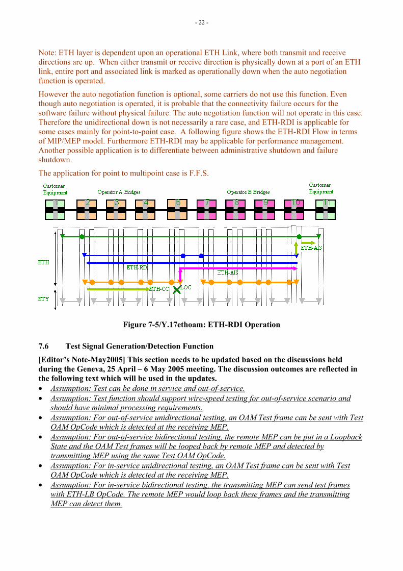
Note: ETH layer is dependent upon an operational ETH Link, where both transmit and receive directions are up. When either transmit or receive direction is physically down at a port of an ETH link, entire port and associated link is marked as operationally down when the auto negotiation function is operated.
However the auto negotiation function is optional, some carriers do not use this function. Even though auto negotiation is operated, it is probable that the connectivity failure occurs for the software failure without physical failure. The auto negotiation function will not operate in this case. Therefore the unidirectional down is not necessarily a rare case, and ETH-RDI is applicable for some cases mainly for point-to-point case. A following figure shows the ETH-RDI Flow in terms of MIP/MEP model. Furthermore ETH-RDI may be applicable for performance management. Another possible application is to differentiate between administrative shutdown and failure shutdown.
The application for point to multipoint case is F.F.S.
Figure 7-5/Y.17ethoam: ETH-RDI Operation
7.6 Test Signal Generation/Detection Function
[Editor’s Note-May2005] This section needs to be updated based on the discussions held during the Geneva, 25 April – 6 May 2005 meeting. The discussion outcomes are reflected in the following text which will be used in the updates. • Assumption: Test can be done in service and out-of-service. • Assumption: Test function should support wire-speed testing for out-of-service scenario and
should have minimal processing requirements. • Assumption: For out-of-service unidirectional testing, an OAM Test frame can be sent with Test
OAM OpCode which is detected at the receiving MEP. • Assumption: For out-of-service bidirectional testing, the remote MEP can be put in a Loopback
State and the OAM Test frames will be looped back by remote MEP and detected by transmitting MEP using the same Test OAM OpCode.
• Assumption: For in-service unidirectional testing, an OAM Test frame can be sent with Test OAM OpCode which is detected at the receiving MEP.
• Assumption: For in-service bidirectional testing, the transmitting MEP can send test frames with ETH-LB OpCode. The remote MEP would loop back these frames and the transmitting MEP can detect them.
- 23 -
• Question: Will a Test Signal detector always expect a different OAM OpCode (different from other OAM functions)? If Yes, the OAM Test Function would require 2 OpCodes (one for uni-directional and other for bidirectional testing). This would also make it independent of Looped back state of Remote MEP.
• Assumption: The data contained in the test OAM can be PRBS and other patterns. • Configuration is expected to be done for the test signal generator associated with the MEP. • Configuration needed for in-service
o Need for MEG ID validation at MEP while responding to a Test from another MEP is to be determined.
o ME Level* (associated with connection monitoring level) o Priority* o Discard Eligibility*
(will be fixed, and therefore non-configurable) • Configuration needed for out-of-service
o ME Level* (associated with connection monitoring level) o Priority* o Discard Eligibility*
(will be fixed, and therefore non-configurable)
The test signal generation function in a MEP/MIP generates test frame with specified throughput (bandwidth), frame size and frame transmission pattern. The detection function in a MEP/MIP detects throughput (bandwidth), frame loss, frame disorders, bit errors, delay and delay variation.
7.6.1 Test Modes This test function can be used in-service and out-of-service.
When out-of-service is conducted, service cannot be offered to the user. For example, this type of test can be used for pre-service test.
Service can be offered to the user when in-service test is conducted. However, since this test uses some of the bandwidth of the service, agreement needs to be made between the user and the network operator on the bandwidth usage.
7.6.2 Frame Format Since test function needs to be done out-of-service and in-service, Ethernet OAM frame format needs to be used so that test frames can be distinguished from normal user data frame. The length of ETH-Test OAM frames is configurable. It is determined before each ETH-Test process. During a ETH-Test process, all the generated frames have the same length. ETH-Test using non-constant length OAM frames is FFS.
7.6.3 OAM Data In order to measure frame loss and bit error performance, 32bit sequence number and pseudo-random test sequence (2^31-1) as specified in 5.8/O.150 are included. OAM data includes FCS.
7.6.4 OAM frame generation process at a transmitting MEP
7.6.4.1 In-service test ETH-Test OAM frames are generated with a fixed interval and inserted into the frame stream at a transmitting MEP. Interval should be calculated from the desired test signal bit rate and the length of OAM frames.
- 24 -
7.6.4.2 Out-of-service test User frames are interrupted (discarded) at a transmitting MEP when out-of-service ETH-Test function is conducted. ETH-Test OAM frames are generated with a fixed interval and transmitted. Interval should be calculated from the desired test signal bit rate and the length of OAM frames.
7.6.5 OAM frame reception process at a receiving MEP
7.6.5.1 In-service test ETH-Test OAM frames are extracted from the receiving frame stream at a receiving MEP. ETH-Test OAM frames are identified as the same way as the other OAM frames (i.e., OAM Ether Type and Op Code). Frame losses and frame mis-insertions are detected from the sequence numbers of the received ETH-Test OAM frames. Bit errors are detected from the pseudo-random sequence of the received ETH-Test OAM frames.
7.6.5.2 Out-of-service test All the received frames are extracted from the receiving frame stream at a receiving MEP. Received frames other than ETH-OAM frames are identified as mis-inserted frames. ETH-Test OAM frames are identified as the same way as the other OAM frames (i.e., OAM Ether Type and Op Code). Frame losses and additional frame mis-insertions are detected from the sequence numbers of the received ETH-Test OAM frames. Bit errors are detected from the pseudo-random sequence of the received ETH-Test OAM frames.
7.6.6 Maintenance Scenarios This section shows some examples of maintenance scenarios for point-to-point, in-service and out-of-service case.
NOTE: Multipoint application is FFS.
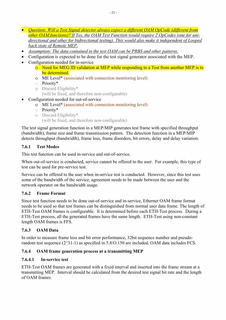
7.6.6.1 Unidirectional Measurement A MEP at an edge bridge generates a test frame and another MEP in an edge bridge receives the test frame and measures the performance between these two edge bridges MEPs (Figure 7-6.1). This scenario is applicable both to in-service test and out-of-service test.
Figure 7-6.1/Y.ethoam: Unidirectional Test
- 25 -
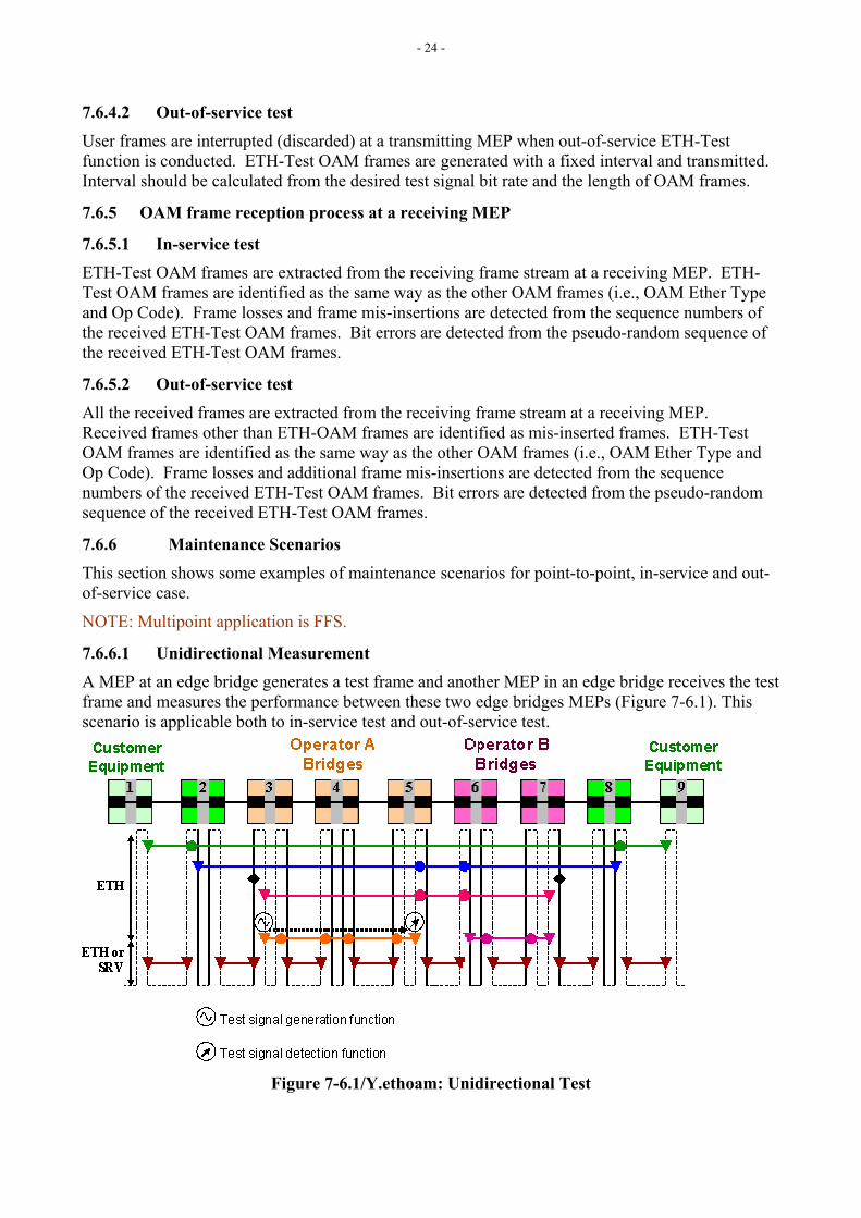
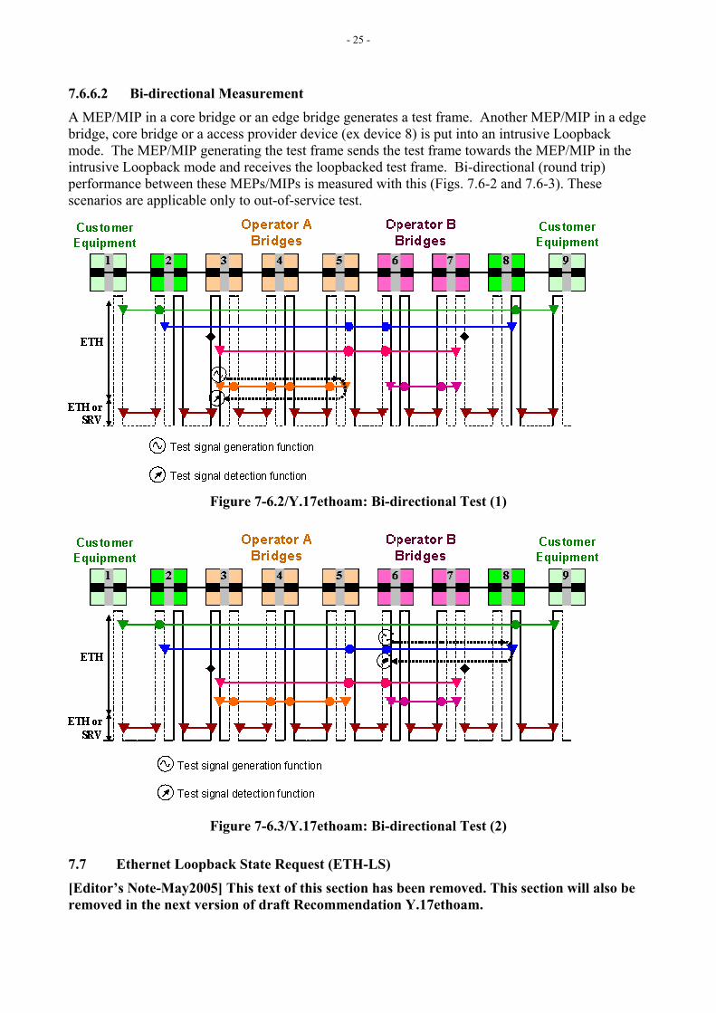
7.6.6.2 Bi-directional Measurement A MEP/MIP in a core bridge or an edge bridge generates a test frame. Another MEP/MIP in a edge bridge, core bridge or a access provider device (ex device 8) is put into an intrusive Loopback mode. The MEP/MIP generating the test frame sends the test frame towards the MEP/MIP in the intrusive Loopback mode and receives the loopbacked test frame. Bi-directional (round trip) performance between these MEPs/MIPs is measured with this (Figs. 7.6-2 and 7.6-3). These scenarios are applicable only to out-of-service test.
Figure 7-6.2/Y.17ethoam: Bi-directional Test (1)
Figure 7-6.3/Y.17ethoam: Bi-directional Test (2)
7.7 Ethernet Loopback State Request (ETH-LS)
[Editor’s Note-May2005] This text of this section has been removed. This section will also be removed in the next version of draft Recommendation Y.17ethoam.
- 26 -
Assumption: It was decided that ETH-LS would require some management controls around it. And therefore the functionality of the ETH-LS is redundant since the Loopback State can be set by the management entity.
7.8 Ethernet Automatic Protection Switching (ETH-APS) Details of ETH-APS mechanism will be provided in Recommendation G.ethps.
[Editor’s Note-May2005] Specific requirements from G.ethps on Y.17ethoam e.g. OAM mechanisms required to support ETH-APS functionality will need to be identified before August-September 2005 meeting. Any requirements identified later will be covered in a later version of Y.17ethoam.
8 OAM Functions for Performance Management
[Editor’s Note-May2005] This section needs to be updated based on the discussions held during the Geneva, 25 April – 6 May 2005 meeting.
[Editor’s Note-Mar2005] Details regarding the specific OAM frame types will be moved into a new Section 9.
8.1 Performance Parameters Following performance parameters are based on Metro Ethernet Forum (MEF) specification MEF 10 [7], which specifies Ethernet service attributes. These parameters are currently defined for point-to-point ETH connections. Performance parameters for multipoint ETH connectivity are for FFS.
• Frame Loss Ratio (FLR) FLR is defined as a ratio, expressed as a percentage, of the number of service frames not delivered divided by the number of service frames, where the number of service frames not delivered is the difference between the number of service frames sent to ingress UNI and the number of service frames received at egress UNI.
• Frame Delay (FD) FD can be specified as round-trip delay for a frame, where FD is defined as the time elapsed since start of transmission of the first bit of the frame by a source node until the reception of the last bit of the loop backed frame by the same source node, when the loop back is performed at the frame’s destination node.
• Frame Delay Variation (FDV) FDV is a measure of the variations in the Frame Delay (FD) between a pair of Service Frames, where the service frames belong to the same CoS instance on a point-to-point ETH connection.
Note: For sub rate or virtual services, the frame loss can be associated with both in-profile and out-of-profile service frames.
Additional performance parameters that may be taken into consideration include:
• Availability Availability is a function of time that a ME (associating service UNIs) is in available state. It is specified as a ratio of:
Availability = Time ME is in Available State / Total Time,
- 27 -
where, Total Time is viewed as number of time intervals and Available State is viewed as interval when ME meets FLR, FD and FDV bounds. Unavailable state is encountered when at least one of the FLR, FD or FDV measures exceed their bounds/thresholds during a time interval. These bounds/thresholds are determined by the class of service (CoS)
[Editor’s Note-Jan2005] Definition of Availability should be aligned with Y.1711 and/or Y.MPLSperf. Details of Availability are expected to be defined in a separate recommendation in SG12. • Errored Frame Seconds
An Errored Frame Second indicates that an error (e.g., frame error due to FCS or 8B/10B coding violation) has occurred within the second. This does not take into consideration errors when frames are received error free but are not delivered.
• Service Status Service Status indicates if an ME is in-service or out-of-service. In-service or out-of-service state can be based on Available State defined earlier.
• Frame Throughput Number of frames and/or bytes transmitted to a network interface relative to Committed Information Rate (CIR)
• Frame Tx Number of frames transmitted out of an interface within a time interval (e.g. 1 second).
• Frame Rx Number of frames received from on an interface within a time interval (e.g. 1 second).
• Frame Drop Number of frames dropped at an interface within a time interval (e.g. 1 second).
• Unavailable Time Number of time intervals (e.g. 1 second) when the ME is out-of-service.
[Editor’s Note-Jan2005] Atomic function model similar to Section 7 is needed here. Contributions are invited.
8.2 Frame Loss Data Collection (ETH-LM)
[Editor’s Note-May2005] This section needs to be updated based on the discussions held during the Geneva, 25 April – 6 May 2005 meeting. The discussion outcomes are reflected in the following text which will be used in the updates. Also consider the WD18r01 for LM considerations. • Assumption: These measurements are being done for p2p specifically. MP is FFS. • Assumption: LM contributes to the unavailable time. • Assumption: A bidirectional service is defined as unavailable if either of the two directions is
declared as unavailable. Therefore, the measurements made on the one end need to be communicated to the other end.
• Assumption: The Near End (NE) and Far End (FE) signals contribute to the NSES (Near End Severely Errored Seconds) and FSES (Far End SES) which together contribute to the unavailable time.
• The above assumptions are based on G.826, G.7710 (Section 10.2).
- 28 -
• Assumptions: The LM is done using the counters which capture the in-profile (i.e. after the TCP). These counters needed to be specified for the current equipments. These would be determined based on the service specifications e.g. no of frames, no of bytes etc. This would be eventually captured in the equipment specification G.8021.
• Question: Q.17/12 would be requested to recommend which counts would be needed i.e. frames or bytes?
• Assumption: The LM mechanisms allow the carrying of the received frame/byte counts and transmitted frame/byte counts to allow the LM measurements as specified in the draft.
• Assumption: The LM request communicates the counts received. The LM reply communicates the counts transmitted + received count value in the LM request.
• Assumption: You send the running counts for the received and transmitted frames (FRC and FTC are running counts)
• Assumption: The A-Z and Z-A are needed separately, both ends control their own LM. • Assumption: dLOC represents the case when 100% frames are lost. Therefore, the LM results
get ignored in the equipment when the dLOC is present. • Assumption: The LM frames do not need to be checked for validation since it is assumed that
LM is run together with the CC. o Same configuration as for Unicast LB. o Periodicity
ETH-LM can be used to collect performance data collection between a pair of flow points. ETH-LM is performed by sending a request ETH-LM frame to a remote flow point and expecting an ETH-LM reply frame back which allows collection of the performance data. ETH-LM provides a generic performance data collection mechanism which can be used to collect information across different managed objects e.g. using TLVs as information elements instead of specific information elements.
Though ETH-LM may be initiated any time, it is particularly useful when carried out periodically.
Note: Unsolicited performance data collection is also possible where unsolicited periodic mechanisms like ETH-CC can be used to also carry performance data e.g. using additional TLVs. However, such additional TLVs have not yet been considered in ETH-CC.
ETH-LM request frame is sent from a MEP to a specific MEP (with DA = Unicast MAC address of destination flow point). Upon reception of this request frame, the MEP responds back with ETH-LM reply frame (with DA = Unicast MAC address of requesting flow point, learnt from request frame). Other flow points that receive this request and/or reply Unicast ETH-LM frame forward these without processing.
Application of ETH-LM for multipoint ETH connectivity is for FFS.
8.2.1 ETH-LM Operations
8.2.1.1 ETH-LM Transmission ETH-LM request frame can be transmitted by a MEP either automatically (i.e. when periodical) or by operator initiated command (via the CLI or EMS/NMS management interfaces, e.g. SNMP MIBs). The Transaction identifier transmitted is retained for at least 5 seconds after the ETH-LM frame is transmitted. The Transaction Identifier must be changed for every ETH-LM frame, and no Transaction Identifier from the same MEP may be repeated within one minute.
- 29 -
8.2.1.2 ETH-LM Reception and Reply Transmission Whenever a valid ETH-LM request frame is received by a MIP or MEP diagnostic flow termination function, the received TLVs are processed and an ETH-LM reply frame is generated and transmitted to the requesting MEP. Fields in the ETH-LM request frame, which request information, are copied to the ETH-LM reply frame with the requested information filled in.
8.2.1.3 ETH-LM Reply Reception When ETH-LM reply frame is received by a MIP diagnostic flow termination function, or if the received Transaction ID is not in the list of transmitted Transaction IDs maintained by the MEP, the ETH-LM reply frame is invalid. The MEP diagnostic flow termination function may examine the TLVs returned in the ETH-LM reply frame, and declare the frame invalid if the requested TLVs are missing. If the ETH-LM reply frame is valid, performance measurements are carried out.
8.3 Frame Loss Ratio (FLR) Measurement
8.3.1 FLR Measurement using ETH-lM
8.3.1.1 ETH-LM Transmission A MEP sends ETH-LM request frame to specific MEP every N seconds (e.g. N=1) with managed objects TLVs corresponding to the performance data.
When applied across UNI_C to UNI_C ME, requesting MEP includes its FramesTransmittedOK value at egress service UNI and requests FramesReceivedOK value at receiver’s ingress service UNI.
Similarly, when applied across UNI_N to UNI_N ME, requesting MEP sends FramesReceivedOK value at ingress service UNI and requests FramesTransmittedOK value at receiver’s egress service UNI.
8.3.1.2 ETH-LM Reception and Reply Transmission Upon receiving the ETH-LM request frame, the receiving MEP compares received managed object TLVs with its own managed objects and sends an ETH-LM reply frame back to requesting MEP with requested managed object TLVs.
When applied across UNI_C to UNI_C ME, receiving MEP compares received FramesTransmittedOK value with its own FramesReceivedOK value and responds with its FramesTransmittedOK value.
Similarly, when applied across UNI_N to UNI_N ME, receiver compares received FramesReceivedOK value with its FramesTransmittedOK value and responds with its FramesTransmittedOK value.
8.3.1.3 ETH-LM Reply Reception Upon receiving ETH-LM reply frame, requesting MEP compares sent managed object TLVs with received managed object TLVs, in a manner similar to the receiving MEP.
8.3.1.4 FLR Measurement For two consecutive ETH-LM operations, the FLR can be measured as:
Frame Loss Ratio = {|CT2-CT1| - |CR2-CR1|}/{|CT2-CT1|}, where CT and CR are FramesTransmittedOK and FramesReceivedOK counts.
- 30 -
Consecutive ETH-LM operations help in reducing error introduced by in-flight frames and lack of timing synchronization between requesting MEP and receiving MEP. Within a measurement time interval, the FLR can be averaged to improve the accuracy of this measurement.
NOTE: For measurement considerations with possible wrapping of CT/CR, refer to Appendix V
The above method can be applied for measuring network level Frame Loss. The network level frame loss can be measured within the network independent of the services.
For non-dedicated point-to-point service types with multiplexed service UNI, where a UNI carries more than one service flow, it is possible to measure FL when data path MOs per service instance are supported.
8.3.2 FLR Measurement using ETH-CC
8.3.2.1 ETH-CC Transmission When supported across ETH-CC, additional TLVs corresponding to the performance data can be included in ETH-CC when used across point-to-point ETH connection. When applied across UNI_N to UNI_N ME, ETH-CC frame is sent as often as the configured transmission interval. The transmitting MEP includes FramesTransmittedOK TLV containing value of FramesTransmittedOK at ingress service UNI.
8.3.2.2 ETH-CC Reception Upon receiving this ETH-CC frame, receiving MEP compares FramesTransmittedOK TLV with FramesReceivedOK value at egress service UNI.
8.3.2.3 FLR Measurement For two such consecutive ETH-CC frames, the FLR can be measured as:
Frame Loss Ratio = {|CT2-CT1| - |CR2-CR1|}/{|CT2-CT1|}, where CT and CR are FramesTransmittedOK and FramesReceivedOK counts.
Consecutive ETH-CC frames help in reducing error introduced by in-flight frames and lack of timing synchronization between transmitting and receiving MEPs. Within a measurement time interval, the FLR can be averaged to improve the accuracy of this measurement.
NOTE: For measurement considerations with possible wrapping of CT/CR, refer to Appendix V
8.3.3 Statistical Method Alternatively, for multipoint-to-multipoint ETH connecitivty, statistical method across a pair of flow points can be applied to estimate frame loss ratio.
The requesting MEP can send N ETH-LB request frames to a specific MEP and receives M ETH-LB replies back from the recipient such that M <= N. The data path frame loss ratio can be estimated as:
Frame Loss Ratio = (N – M)/N per measurement time interval As noted earlier, statistical methods are less accurate than proposed methods in Section 8.3.1 and 8.3.2.
8.4 Frame Delay (FD) Measurement
[Editor’s Note-May2005] This section needs to be updated based on the discussions held during the Geneva, 25 April – 6 May 2005 meeting. The discussion outcomes are reflected in the following text which will be used in the updates.
- 31 -
• Assumption: These measurements are being done for p2p specifically. MP is FFS. • Assumption: Delay Measurement is done for round-trip since one-way measurement requires
synchronization of the clocks. • Assumption: If however, the clocks are synchronized, one-way delay measurement can also be
supported. • Assumption: There should be minimal processing involved at the receiver of the DM request. • Assumption: The message will be specifically targeted to the receiving MEP. • Assumption: The transmitting MEP would put a timestamp in the frame and receiver would
simply turn it around changing the SA, DA. • Assumption: The DM and Error Performance Monitoring are two separate functions and will
be aggregated in the equipment specification. • Assumption: The FD would be run periodically and the start and stop would be controlled via
external commands/triggers to the MEP. • Since Unicast LB does the same thing, we would use the LB with timestamp for this purpose. • Question: Does the FD contribute to the unavailable time? Is the assumption that only one-way
measurements contribute to the unavailable time accurate? If it does than the results of the measurements from the sink would need to be communicated to the head end. These questions will be asked to the Q.17/12 (also Q.4/13???)
• Question: Should round-trip DM really require a separate OpCode since the processing point of the LB for on-demand diagnostics and the processing point for purposes of DM could be quite different. The two would need to be differentiated. Coordination of the transaction ID would be an issue and a separate OpCode might be relatively easier to deal with.
o Same configuration as for Unicast LB o Periodicity
Round-trip Frame Delay (FD) can be measured using ETH-LB.
8.4.1 FD Measurement using ETH-LB
8.4.1.1 ETH-LB Transmission A MEP sends ETH-LB request frame with its “transmission timestamp” to specific MEP every N seconds (e.g. N=1).
8.4.1.2 ETH-LB Reception and Reply Transmission Upon receiving the ETH-LB request frame, the receiving MEP generates a ETH-LB reply frame and transmits it to the requesting MEP. Every field in the Unicast ETH-LB request frame is copied to the Unicast ETH-LB reply frame with the following exceptions:
• The source and destination MAC addresses are swapped.
• The OpCode field is changed from ETH-LB Request to ETH-LB Reply.
• The Checksum TLV is recalculated to reflect any changes to the message, such as the OpCode field.
8.4.1.3 ETH-LB Reply Reception Upon receiving ETH-LB reply frame, requesting MEP compares the transmission timestamp value in ETH-LB reply frame with the time of its reception.
8.4.1.4 FLR Measurement For an ETH-LB operation:
FD = tr – tt,
- 32 -
where tr and tt are Reception Time and Transmission Time respectively.
8.5 Frame Delay Variation (FDV) Measurement
[Editor’s Note-May2005] This section needs to be updated based on the discussions held during the Geneva, 25 April – 6 May 2005 meeting. The discussion outcomes are reflected in the following text which will be used in the updates. • Assumption: These measurements are being done for p2p specifically. MP is FFS. • Assumption: Delay Variation Measurement can be done for both round-trip and one-way
measurement. • Assumption: For the purposes of the round-trip delay variation measurement, we can use LB. • Assumption: For one-way FDV measurement, we need a separate OpCode. • Since we may need to run FDV for multiple priorities, it was felt that CC may not be a good
vehicle for one-way FDV since we may not want to run CC at different priorities simultaneously.
• Assumption: The FDV would be run periodically and the start and stop would be controlled via external commands/triggers to the MEP.
• Question: Does the FDV contribute to the unavailable time? Is the assumption that only one-way measurements contribute to the unavailable time accurate? If it does than the results of the measurements from the sink would need to be communicated to the head end. These questions will be asked to the Q.17/12 (also Q.4/13???)
o Same configuration as for Unicast LB for both round-trip and one-way. o Periodicity
One-way Frame Delay Variation (FDV) can be measured using ETH-CC. Two-way FDV can be measured using ETH-LB.
8.5.1 FDV Measurement using ETH-LB
8.5.1.1 ETH-LB Transmission A MEP sends ETH-LB request frame with its “transmission timestamp” to a specific MEP every N seconds (e.g. N=1).
8.5.1.2 ETH-LB Reception and Reply Transmission Upon receiving the ETH-LB request frame, the receiving MEP generates an ETH-LB reply frame and transmits it to the requesting MEP. Every field in the Unicast ETH-LB request frame is copied to the Unicast ETH-LB reply frame with the following exceptions:
• The source and destination MAC addresses are swapped.
• The OpCode field is changed from ETH-LB Request to ETH-LB Reply.
• The Checksum TLV is recalculated to reflect any changes to the message, such as the OpCode field.
8.5.1.3 ETH-LB Reply Reception Upon receiving ETH-LB reply frame, requesting MEP compares the transmission timestamp value in ETH-LB reply frame with the time of its reception.
8.5.1.4 FLR Measurement FDV for two ETH-LB operations:
FDV = FD2 – FD1,
- 33 -
where FD2 and FD1are Frame Delay measurements for the two ETH-LB operations.
8.5.2 FDV Measurement using ETH-CC
8.5.2.1 ETH-CC Transmission Transmitting MEP transmits ETH-CC with its “transmission timestamp”.
8.5.2.2 ETH-CC Reception Upon receiving the ETH-CC frame, receiving MEP makes note of the “transmission timestamp”.
8.5.2.3 FDV Measurement For each received ETH-CC frame, the receiver can compare the transmission timestamp with the reception time to calculate a relative one-way frame delay.
FD∆ = tr – tt + ∆, where ∆ is the different in the time clocks
For two such consecutive ETH-CC frames, one-way FDV can be measured as:
FDV = FD∆2 - FD∆1,
where FD∆1 and FD∆2 are relative one way frame delays.
8.6 Availability Measurement
8.6.1 Measurement Method Measurement is based on FLR, FD and FDV methods. Availability time interval (e.g. 24hr) can be divided into measurement time intervals (e.g. 1 minute). FLR, FD and FDV are measured per measurement time interval. If any of the three measures cross their thresholds during the measurement time interval, the measurement time interval is considered to be unavailable otherwise it is considered to be available.
Availability = {(# of available measurement time intervals)/(# of total measurement time intervals)}x100%
Note: Mechanisms that can be used to measure availability are being proposed here but they will depend on the definition of availability and further details expected to be specified by Ethernet Traffic Management activities (SG12).
8.7 Other Measurements As per the unsolicited method using ETH-CC, the following parameters can be sent every time interval (e.g. 1 second).
8.7.1 Errored Frame Seconds Within 1 second, check if any increments in (aFrameCheckSequenceErrors, aAlignmentErrors, aFramesAbortedDueToXsColls, aFramesLostDueToIntMACXmitError, aCarrierSenseErrors, aFrameLostDueToIntMACRcvError)
If yes, declare that 1 second as Errored Frame Second
8.7.2 Service Status Within the measurement time interval (e.g. 1 min), declare whether the service is up or down as per availability measurement, explained earlier
- 34 -
8.7.3 Frame Throughput Within the measurement time interval, aFramesTransmittedOK at egress UNI_N relative to CIR
8.7.4 Frame Tx Within 1 second, aFramesTransmittedOK at egress UNI_N
8.7.5 Frame Rx Within 1 second, aFramesReceivedOK at ingress UNI_N
8.7.6 Frame Drop Within 1 second, ifInDiscards at ingress UNI_N and ifOutDiscards at egress UNI_N.
8.7.7 Unavailable Time This is related to availability definition with the unavailable time intervals being counted within the observation period.
9. OAM Frame Types and Information Elements
[Editor’s Note-May2005] This section needs to be updated based on the discussions held during the Geneva, 25 April – 6 May 2005 meeting.
9.1 ETH-CC Frame Information specifically required to be carried in an ETH-CC frames, in support of functionality identified in Section 7.1, includes: • MEG ID • MEP ID • ME Level • Priority • Discard Eligibility • Lifetime?
9.2 Unicast ETH-LB
9.2.1 Unicast ETH-LB Request Frame Information specifically required to be carried in a Unicast ETH-LB request frames, in support of functionality identified in Section 7.2.1, includes: • ME Level • Priority • Discard Eligibility • Transaction Identifier
9.2.2 Unicast ETH-LB Reply Frame Information specifically required to be carried in a Unicast ETH-LB reply frames, in support of functionality identified in Section 7.2.1, includes: • ME Level • Priority • Discard Eligibility • Transaction Identifier
- 35 -
9.3 Multicast ETH-LB
9.3.1 Multicast ETH-LB Request Frame Information specifically required to be carried in a Multicast ETH-LB request frames, in support of functionality identified in Section 7.2.2, includes: • MEG ID • ME Level • Priority • Discard Eligibility • Transaction Identifier
9.3.2 Unicast ETH-LB Reply Frame Information specifically required to be carried in a Unicast ETH-LB reply frames, in support of functionality identified in Section 7.2.2, includes: • MEG ID • MEP ID • ME Level • Priority • Discard Eligibility • Transaction Identifier
9.4 ETH-LT
9.4.1 ETH-LT Request Frame Information specifically required to be carried in an ETH-LT request frames, in support of functionality identified in Section 7.3, includes: • MEG ID • ME Level • Priority • Discard Eligibility • Transaction Identifier • Source MAC Address • Target MAC Address • TTL
9.4.2 ETH-LT Reply Frame Information specifically required to be carried in an ETH-LT reply frames, in support of functionality identified in Section 7.3, includes: • MED ID • ME Level • Priority • Discard Eligibility • Transaction Identifier • TTL
- 36 -
10 OAM Frame Format
[Editor’s Note-May2005] This section needs to be updated based on the discussions held during the Geneva, 25 April – 6 May 2005 meeting.
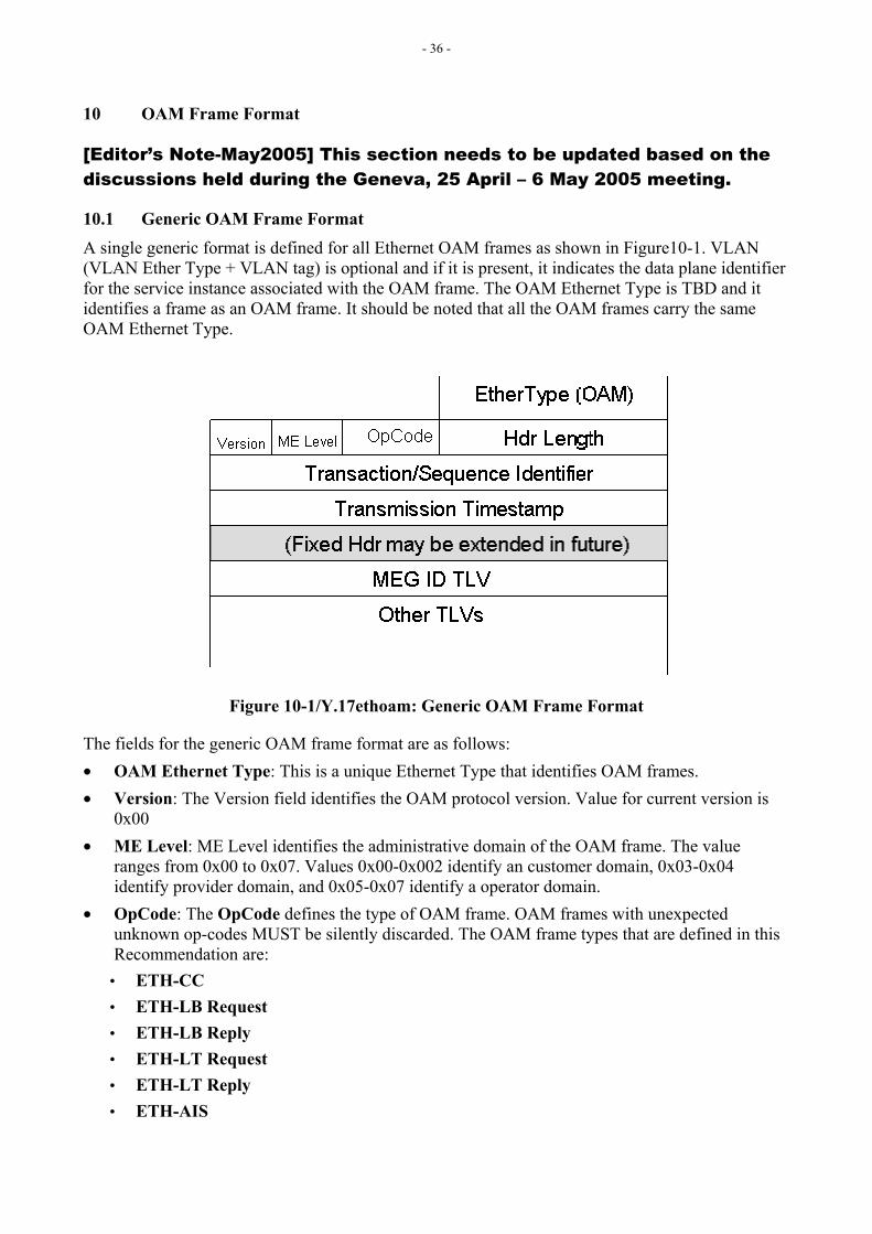
10.1 Generic OAM Frame Format A single generic format is defined for all Ethernet OAM frames as shown in Figure10-1. VLAN (VLAN Ether Type + VLAN tag) is optional and if it is present, it indicates the data plane identifier for the service instance associated with the OAM frame. The OAM Ethernet Type is TBD and it identifies a frame as an OAM frame. It should be noted that all the OAM frames carry the same OAM Ethernet Type.
Figure 10-1/Y.17ethoam: Generic OAM Frame Format
The fields for the generic OAM frame format are as follows: • OAM Ethernet Type: This is a unique Ethernet Type that identifies OAM frames. • Version: The Version field identifies the OAM protocol version. Value for current version is
0x00 • ME Level: ME Level identifies the administrative domain of the OAM frame. The value
ranges from 0x00 to 0x07. Values 0x00-0x002 identify an customer domain, 0x03-0x04 identify provider domain, and 0x05-0x07 identify a operator domain.
• OpCode: The OpCode defines the type of OAM frame. OAM frames with unexpected unknown op-codes MUST be silently discarded. The OAM frame types that are defined in this Recommendation are:
• ETH-CC • ETH-LB Request • ETH-LB Reply • ETH-LT Request • ETH-LT Reply • ETH-AIS
- 37 -
• ETH-RDI • ETH-LM Request • ETH-LM Reply • ETH-APS • ETH-TEST • Vendor Specific. The vendor specific op-code is provided to allow vendors or other
organizations to extend OAM functions in proprietary ways. • Hdr Length: The number of bytes in the fixed-length header, starting with the Version field. • Transmission/Sequence Identifier: Supplied by the originator of OAM request and copied in
the OAM reply. Semantics of this field are dependent on the OpCode. • Transmission Timestamp: Time at which the OAM frame was transmitted from originating
MEP. When this field is not used, a value of all zeros should be used. • MEG ID: The first TLV that identifies the MEG. • Other TLVs: These TLVs correspond to OAM frame type.
Note: For further protocol details related to Connectivity Fault Management Related OpCode (e.g. ETH-CC, ETH-LB, ETH-LT, ETH-AIS and ETH-RDI), refer to IEEE 802.1ag.
[Editor’s Note-Mar2005] Coordination is required with IEEE 802.1 regarding allocation of OpCodes as identified in this Recommendation.
10.2 Addressing Discussion
10.2.1 ETH-CC The ETH-CC frame is generated with a specific multicast Destination Address. As a result, ETH-CC can be used to discover the MAC addresses associated with MEPs.
10.2.2 ETH-LT Request The ETH-LT request frame is generated with a specific multicast Destination Address (DA).
A multicast DA is used instead of Unicast DA for ETH-LT request frame since in case of a shared media, a Unicast DA would result in multiple MIPs at the shared media sending responses, which would be undesirable. Also in current bridges, the MIPs would not be able to intercept a Unicast DA and therefore the MIPs would not be able to reply and would simply forward the ETH-LT request frame with Unicast DA. The limitation is that current ports do not look at the EtherType before looking at the DA.
[Editor’s Note-May2005] Question.Q.12/15, Q.9/15 – Is a shared media relevant in Transport Networks? Further to allow MIPs in current devices that do the bridge model, to terminate the ETH-LT request frame for processing before forwarding it, ETH-LT request frame is sent to a multicast DA at a ME Level 1 less than the MIP’s ME Level. This is done since a MIP is expected to forward ETH-CCs transparently at MIP’s ME Level (where ETH-CC frames use a multicast DA at the MIP’s ME Level).
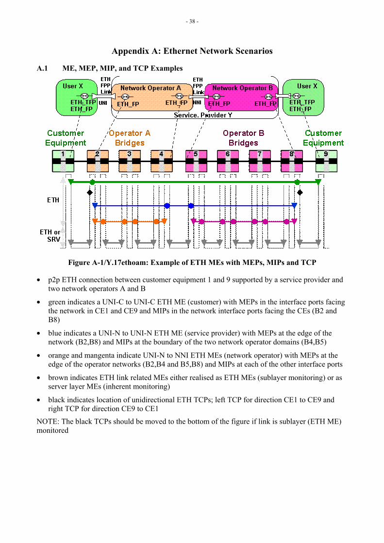
- 38 -
Appendix A: Ethernet Network Scenarios
A.1 ME, MEP, MIP, and TCP Examples
Figure A-1/Y.17ethoam: Example of ETH MEs with MEPs, MIPs and TCP
• p2p ETH connection between customer equipment 1 and 9 supported by a service provider and two network operators A and B
• green indicates a UNI-C to UNI-C ETH ME (customer) with MEPs in the interface ports facing the network in CE1 and CE9 and MIPs in the network interface ports facing the CEs (B2 and B8)
• blue indicates a UNI-N to UNI-N ETH ME (service provider) with MEPs at the edge of the network (B2,B8) and MIPs at the boundary of the two network operator domains (B4,B5)
• orange and mangenta indicate UNI-N to NNI ETH MEs (network operator) with MEPs at the edge of the operator networks (B2,B4 and B5,B8) and MIPs at each of the other interface ports
• brown indicates ETH link related MEs either realised as ETH MEs (sublayer monitoring) or as server layer MEs (inherent monitoring)
• black indicates location of unidirectional ETH TCPs; left TCP for direction CE1 to CE9 and right TCP for direction CE9 to CE1
NOTE: The black TCPs should be moved to the bottom of the figure if link is sublayer (ETH ME) monitored
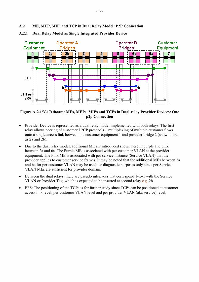
- 39 -
A.2 ME, MEP, MIP, and TCP in Dual Relay Model: P2P Connection
A.2.1 Dual Relay Model as Single Integrated Provider Device
Figure A-2.1/Y.17ethoam: MEs, MEPs, MIPs and TCPs in Dual-relay Provider Devices: One p2p Connection
• Provider Device is represented as a dual relay model implemented with both relays. The first relay allows peering of customer L2CP protocols + multiplexing of multiple customer flows onto a single access link between the customer equipment 1 and provider bridge 2 (shown here as 2a and 2b).
• Due to the dual relay model, additional ME are introduced shown here in purple and pink between 2a and 6a. The Purple ME is associated with per customer VLAN at the provider equipment. The Pink ME is associated with per service instance (Service VLAN) that the provider applies to customer service frames. It may be noted that the additional MEs between 2a and 6a for per customer VLAN may be used for diagnostic purposes only since per Service VLAN MEs are sufficient for provider domain.
• Between the dual relays, there are pseudo interfaces that correspond 1-to-1 with the Service VLAN or Provider Tag, which is expected to be inserted at second relay e.g. 2b.
• FFS: The positioning of the TCPs is for further study since TCPs can be positioned at customer access link level, per customer VLAN level and per provider VLAN (aka service) level.
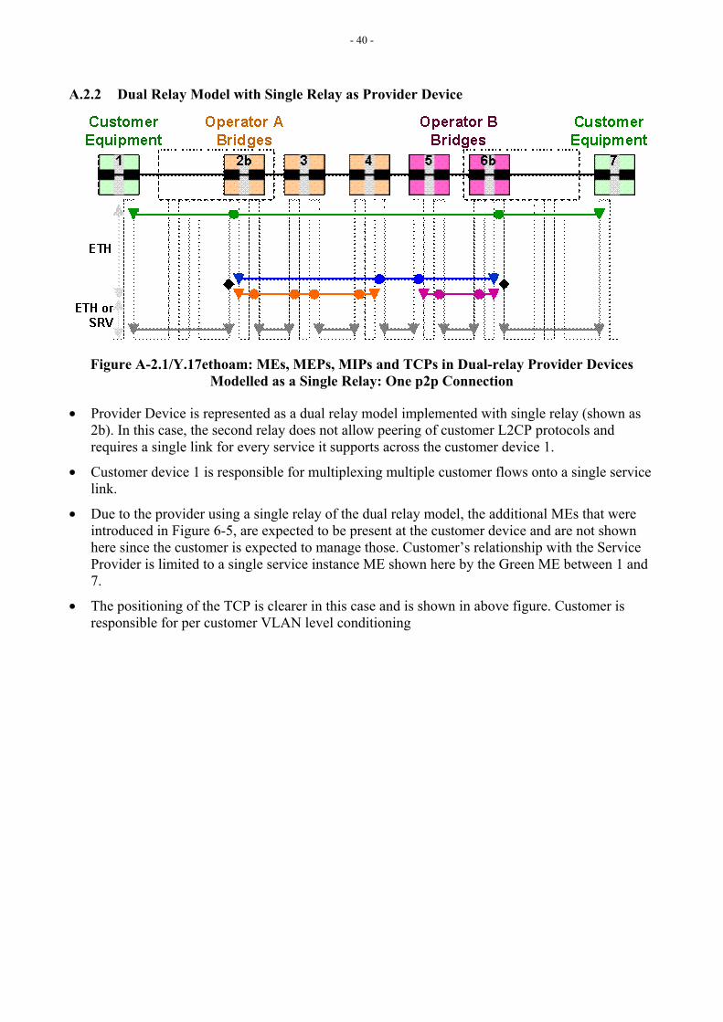
- 40 -
A.2.2 Dual Relay Model with Single Relay as Provider Device
Figure A-2.1/Y.17ethoam: MEs, MEPs, MIPs and TCPs in Dual-relay Provider Devices Modelled as a Single Relay: One p2p Connection
• Provider Device is represented as a dual relay model implemented with single relay (shown as 2b). In this case, the second relay does not allow peering of customer L2CP protocols and requires a single link for every service it supports across the customer device 1.
• Customer device 1 is responsible for multiplexing multiple customer flows onto a single service link.
• Due to the provider using a single relay of the dual relay model, the additional MEs that were introduced in Figure 6-5, are expected to be present at the customer device and are not shown here since the customer is expected to manage those. Customer’s relationship with the Service Provider is limited to a single service instance ME shown here by the Green ME between 1 and 7.
• The positioning of the TCP is clearer in this case and is shown in above figure. Customer is responsible for per customer VLAN level conditioning
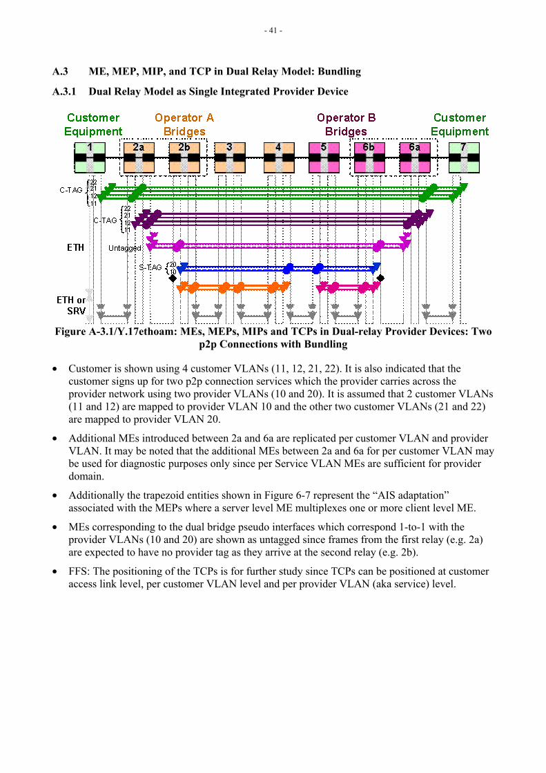
- 41 -
A.3 ME, MEP, MIP, and TCP in Dual Relay Model: Bundling
A.3.1 Dual Relay Model as Single Integrated Provider Device
Figure A-3.1/Y.17ethoam: MEs, MEPs, MIPs and TCPs in Dual-relay Provider Devices: Two p2p Connections with Bundling
• Customer is shown using 4 customer VLANs (11, 12, 21, 22). It is also indicated that the customer signs up for two p2p connection services which the provider carries across the provider network using two provider VLANs (10 and 20). It is assumed that 2 customer VLANs (11 and 12) are mapped to provider VLAN 10 and the other two customer VLANs (21 and 22) are mapped to provider VLAN 20.
• Additional MEs introduced between 2a and 6a are replicated per customer VLAN and provider VLAN. It may be noted that the additional MEs between 2a and 6a for per customer VLAN may be used for diagnostic purposes only since per Service VLAN MEs are sufficient for provider domain.
• Additionally the trapezoid entities shown in Figure 6-7 represent the “AIS adaptation” associated with the MEPs where a server level ME multiplexes one or more client level ME.
• MEs corresponding to the dual bridge pseudo interfaces which correspond 1-to-1 with the provider VLANs (10 and 20) are shown as untagged since frames from the first relay (e.g. 2a) are expected to have no provider tag as they arrive at the second relay (e.g. 2b).
• FFS: The positioning of the TCPs is for further study since TCPs can be positioned at customer access link level, per customer VLAN level and per provider VLAN (aka service) level.
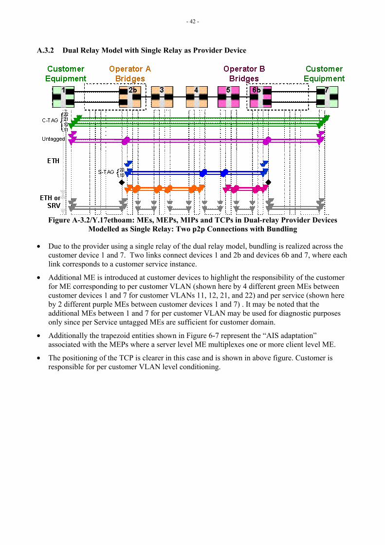
- 42 -
A.3.2 Dual Relay Model with Single Relay as Provider Device
Figure A-3.2/Y.17ethoam: MEs, MEPs, MIPs and TCPs in Dual-relay Provider Devices Modelled as Single Relay: Two p2p Connections with Bundling
• Due to the provider using a single relay of the dual relay model, bundling is realized across the customer device 1 and 7. Two links connect devices 1 and 2b and devices 6b and 7, where each link corresponds to a customer service instance.
• Additional ME is introduced at customer devices to highlight the responsibility of the customer for ME corresponding to per customer VLAN (shown here by 4 different green MEs between customer devices 1 and 7 for customer VLANs 11, 12, 21, and 22) and per service (shown here by 2 different purple MEs between customer devices 1 and 7) . It may be noted that the additional MEs between 1 and 7 for per customer VLAN may be used for diagnostic purposes only since per Service untagged MEs are sufficient for customer domain.
• Additionally the trapezoid entities shown in Figure 6-7 represent the “AIS adaptation” associated with the MEPs where a server level ME multiplexes one or more client level ME.
• The positioning of the TCP is clearer in this case and is shown in above figure. Customer is responsible for per customer VLAN level conditioning.
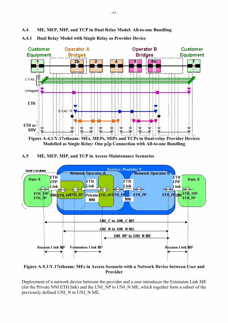
- 43 -
A.4 ME, MEP, MIP, and TCP in Dual Relay Model: All-to-one Bundling
A.4.1 Dual Relay Model with Single Relay as Provider Device
Figure A-4.1/Y.17ethoam: MEs, MEPs, MIPs and TCPs in Dual-relay Provider Devices Modelled as Single Relay: One p2p Connection with All-to-one Bundling
A.5 ME, MEP, MIP, and TCP in Access Maintenance Scenarios
Figure A-5.1/Y.17ethoam: MEs in Access Scenario with a Network Device between User and Provider
Deployment of a network device between the provider and a user introduces the Extension Link ME (for the Private NNI ETH link) and the UNI_NP to UNI_N ME, which together form a subset of the previously defined UNI_N to UNI_N ME.
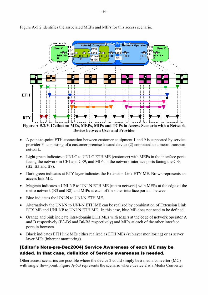
- 44 -
Figure A-5.2 identifies the associated MEPs and MIPs for this access scenario.
Figure A-5.2/Y.17ethoam: MEs, MEPs, MIPs and TCPs in Access Scenario with a Network Device between User and Provider
• A point-to-point ETH connection between customer equipment 1 and 9 is supported by service provider Y, consisting of a customer premise-located device (2) connected to a metro transport network.
• Light green indicates a UNI-C to UNI-C ETH ME (customer) with MEPs in the interface ports facing the network in CE1 and CE9, and MIPs in the network interface ports facing the CEs (B2, B3 and B8).
• Dark green indicates at ETY layer indicates the Extension Link ETY ME. Brown represents an access link ME.
• Magenta indicates a UNI-NP to UNI-N ETH ME (metro network) with MEPs at the edge of the metro network (B3 and B8) and MIPs at each of the other interface ports in between.
• Blue indicates the UNI-N to UNI-N ETH ME.
• Alternatively the UNI-N to UNI-N ETH ME can be realized by combination of Extension Link ETY ME and UNI-NP to UNI-N ETH ME. In this case, blue ME does not need to be defined.
• Orange and pink indicate intra-domain ETH MEs with MEPs at the edge of network operator A and B respectively (B3-B5 and B6-B8 respectively) and MIPs at each of the other interface ports in between.
• Black indicates ETH link MEs either realized as ETH MEs (sublayer monitoring) or as server layer MEs (inherent monitoring).
[Editor’s Note-pre-Dec2004] Service Awareness of each ME may be added. In that case, definition of Service awareness is needed. Other access scenarios are possible where the device 2 could simply be a media converter (MC) with single flow-point. Figure A-5.3 represents the scenario where device 2 is a Media Converter
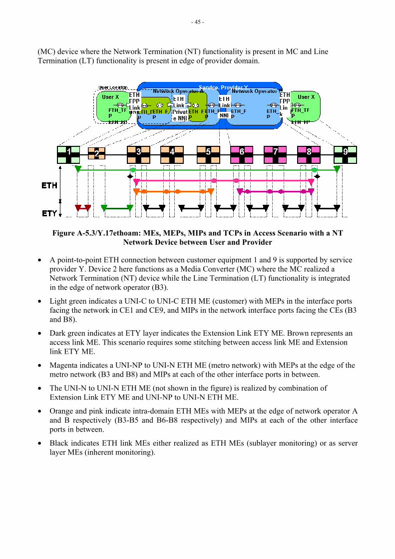
- 45 -
(MC) device where the Network Termination (NT) functionality is present in MC and Line Termination (LT) functionality is present in edge of provider domain.
Figure A-5.3/Y.17ethoam: MEs, MEPs, MIPs and TCPs in Access Scenario with a NT Network Device between User and Provider
• A point-to-point ETH connection between customer equipment 1 and 9 is supported by service provider Y. Device 2 here functions as a Media Converter (MC) where the MC realized a Network Termination (NT) device while the Line Termination (LT) functionality is integrated in the edge of network operator (B3).
• Light green indicates a UNI-C to UNI-C ETH ME (customer) with MEPs in the interface ports facing the network in CE1 and CE9, and MIPs in the network interface ports facing the CEs (B3 and B8).
• Dark green indicates at ETY layer indicates the Extension Link ETY ME. Brown represents an access link ME. This scenario requires some stitching between access link ME and Extension link ETY ME.
• Magenta indicates a UNI-NP to UNI-N ETH ME (metro network) with MEPs at the edge of the metro network (B3 and B8) and MIPs at each of the other interface ports in between.
• The UNI-N to UNI-N ETH ME (not shown in the figure) is realized by combination of Extension Link ETY ME and UNI-NP to UNI-N ETH ME.
• Orange and pink indicate intra-domain ETH MEs with MEPs at the edge of network operator A and B respectively (B3-B5 and B6-B8 respectively) and MIPs at each of the other interface ports in between.
• Black indicates ETH link MEs either realized as ETH MEs (sublayer monitoring) or as server layer MEs (inherent monitoring).
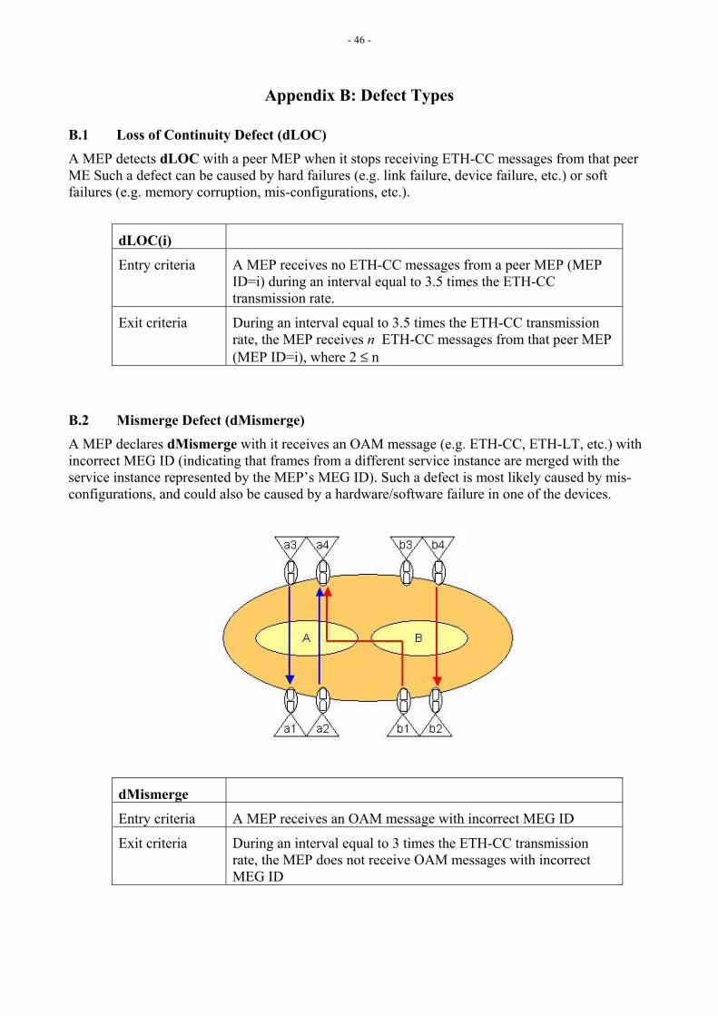
- 46 -
Appendix B: Defect Types
B.1 Loss of Continuity Defect (dLOC) A MEP detects dLOC with a peer MEP when it stops receiving ETH-CC messages from that peer ME Such a defect can be caused by hard failures (e.g. link failure, device failure, etc.) or soft failures (e.g. memory corruption, mis-configurations, etc.).
dLOC(i)
Entry criteria A MEP receives no ETH-CC messages from a peer MEP (MEP ID=i) during an interval equal to 3.5 times the ETH-CC transmission rate.
Exit criteria During an interval equal to 3.5 times the ETH-CC transmission rate, the MEP receives n ETH-CC messages from that peer MEP (MEP ID=i), where 2 ≤ n
B.2 Mismerge Defect (dMismerge) A MEP declares dMismerge with it receives an OAM message (e.g. ETH-CC, ETH-LT, etc.) with incorrect MEG ID (indicating that frames from a different service instance are merged with the service instance represented by the MEP’s MEG ID). Such a defect is most likely caused by mis-configurations, and could also be caused by a hardware/software failure in one of the devices.
dMismerge
Entry criteria A MEP receives an OAM message with incorrect MEG ID
Exit criteria During an interval equal to 3 times the ETH-CC transmission rate, the MEP does not receive OAM messages with incorrect MEG ID
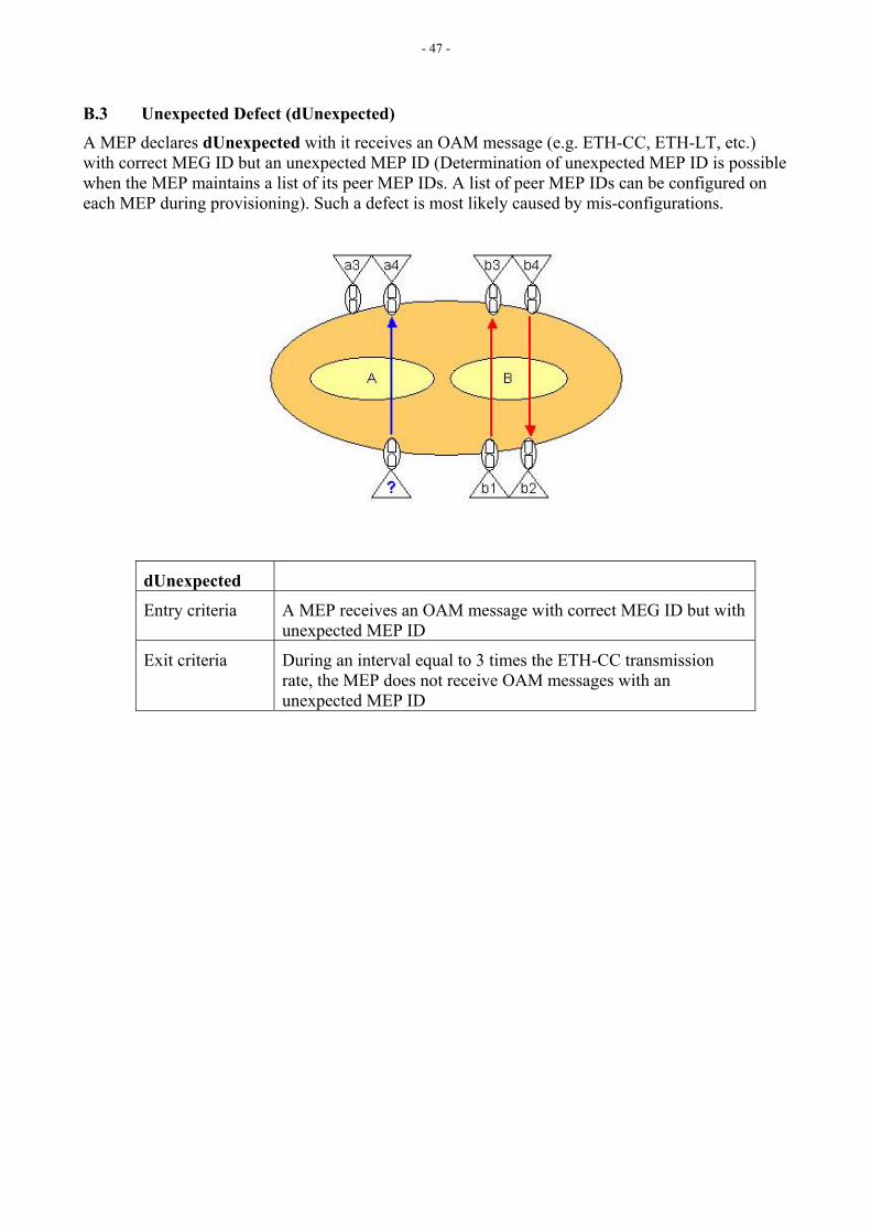
- 47 -
B.3 Unexpected Defect (dUnexpected) A MEP declares dUnexpected with it receives an OAM message (e.g. ETH-CC, ETH-LT, etc.) with correct MEG ID but an unexpected MEP ID (Determination of unexpected MEP ID is possible when the MEP maintains a list of its peer MEP IDs. A list of peer MEP IDs can be configured on each MEP during provisioning). Such a defect is most likely caused by mis-configurations.
dUnexpected
Entry criteria A MEP receives an OAM message with correct MEG ID but with unexpected MEP ID
Exit criteria During an interval equal to 3 times the ETH-CC transmission rate, the MEP does not receive OAM messages with an unexpected MEP ID
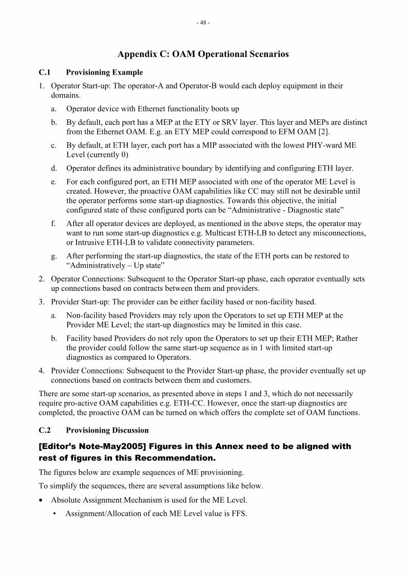
- 48 -
Appendix C: OAM Operational Scenarios
C.1 Provisioning Example 1. Operator Start-up: The operator-A and Operator-B would each deploy equipment in their
domains.
a. Operator device with Ethernet functionality boots up
b. By default, each port has a MEP at the ETY or SRV layer. This layer and MEPs are distinct from the Ethernet OAM. E.g. an ETY MEP could correspond to EFM OAM [2].
c. By default, at ETH layer, each port has a MIP associated with the lowest PHY-ward ME Level (currently 0)
d. Operator defines its administrative boundary by identifying and configuring ETH layer.
e. For each configured port, an ETH MEP associated with one of the operator ME Level is created. However, the proactive OAM capabilities like CC may still not be desirable until the operator performs some start-up diagnostics. Towards this objective, the initial configured state of these configured ports can be “Administrative - Diagnostic state”
f. After all operator devices are deployed, as mentioned in the above steps, the operator may want to run some start-up diagnostics e.g. Multicast ETH-LB to detect any misconnections, or Intrusive ETH-LB to validate connectivity parameters.
g. After performing the start-up diagnostics, the state of the ETH ports can be restored to “Administratively – Up state”
2. Operator Connections: Subsequent to the Operator Start-up phase, each operator eventually sets up connections based on contracts between them and providers.
3. Provider Start-up: The provider can be either facility based or non-facility based.
a. Non-facility based Providers may rely upon the Operators to set up ETH MEP at the Provider ME Level; the start-up diagnostics may be limited in this case.
b. Facility based Providers do not rely upon the Operators to set up their ETH MEP; Rather the provider could follow the same start-up sequence as in 1 with limited start-up diagnostics as compared to Operators.
4. Provider Connections: Subsequent to the Provider Start-up phase, the provider eventually set up connections based on contracts between them and customers.
There are some start-up scenarios, as presented above in steps 1 and 3, which do not necessarily require pro-active OAM capabilities e.g. ETH-CC. However, once the start-up diagnostics are completed, the proactive OAM can be turned on which offers the complete set of OAM functions.
C.2 Provisioning Discussion
[Editor’s Note-May2005] Figures in this Annex need to be aligned with rest of figures in this Recommendation. The figures below are example sequences of ME provisioning.
To simplify the sequences, there are several assumptions like below.
• Absolute Assignment Mechanism is used for the ME Level.
• Assignment/Allocation of each ME Level value is FFS.
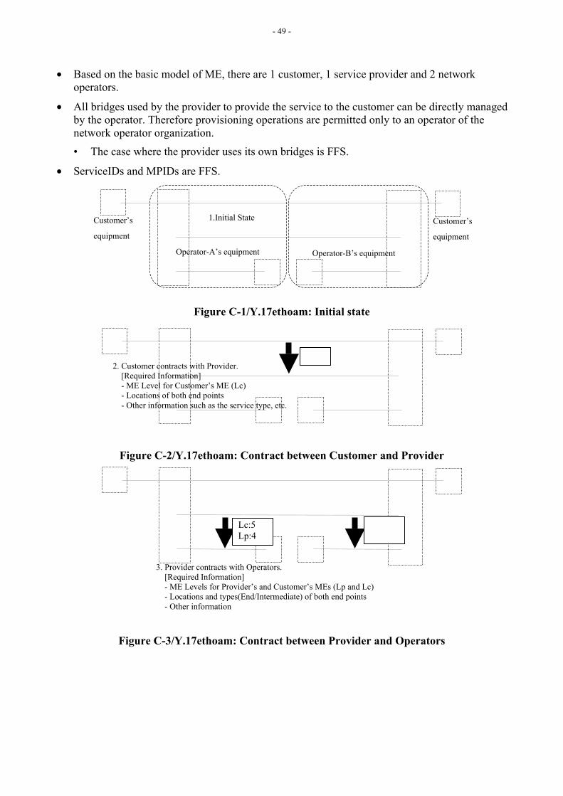
- 49 -
• Based on the basic model of ME, there are 1 customer, 1 service provider and 2 network operators.
• All bridges used by the provider to provide the service to the customer can be directly managed by the operator. Therefore provisioning operations are permitted only to an operator of the network operator organization.
• The case where the provider uses its own bridges is FFS.
• ServiceIDs and MPIDs are FFS.
Figure C-1/Y.17ethoam: Initial state
Figure C-2/Y.17ethoam: Contract between Customer and Provider
Figure C-3/Y.17ethoam: Contract between Provider and Operators
Lc:5 Lp:4
3. Provider contracts with Operators. [Required Information] - ME Levels for Provider’s and Customer’s MEs (Lp and Lc) - Locations and types(End/Intermediate) of both end points - Other information
2. Customer contracts with Provider. [Required Information] - ME Level for Customer’s ME (Lc) - Locations of both end points - Other information such as the service type, etc.
Operator-A’s equipment Operator-B’s equipment
Customer’s
equipment
Customer’s
equipment
1.Initial State
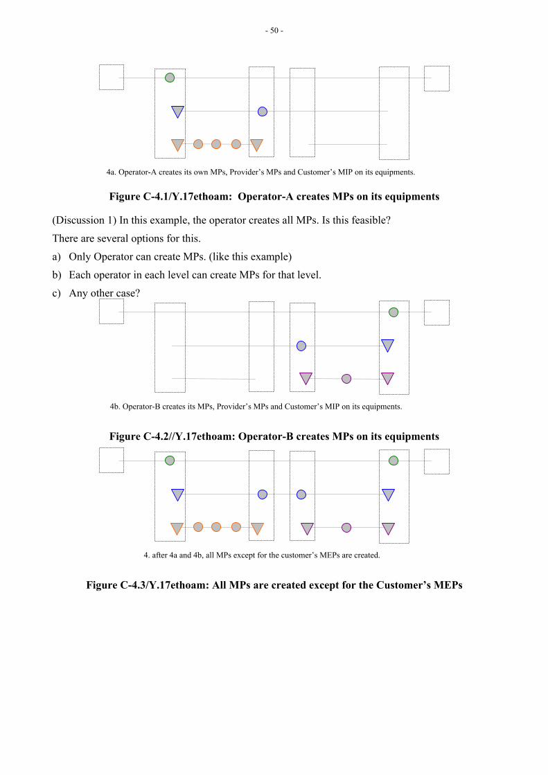
- 50 -
Figure C-4.1/Y.17ethoam: Operator-A creates MPs on its equipments
(Discussion 1) In this example, the operator creates all MPs. Is this feasible?
There are several options for this.
a) Only Operator can create MPs. (like this example)
b) Each operator in each level can create MPs for that level.
c) Any other case?
Figure C-4.2//Y.17ethoam: Operator-B creates MPs on its equipments
Figure C-4.3/Y.17ethoam: All MPs are created except for the Customer’s MEPs
4. after 4a and 4b, all MPs except for the customer’s MEPs are created.
4b. Operator-B creates its MPs, Provider’s MPs and Customer’s MIP on its equipments.
4a. Operator-A creates its own MPs, Provider’s MPs and Customer’s MIP on its equipments.

- 51 -
Figure C-5/Y.17ethoam: Operators activate their MPs
(Discussion 2) In this example, all MPs are at first created and then activated. Therefore MEPs and MIPs must have states, such like “disabled”, “activated” and so on. Do we really have to define these states?
(Discussion 3) How to verify the connectivity of ME? For example, at first MEP to MEP LB will be done, then Link Trace will be used to ensure the route, and finally CC will be started, etc. It is better to clarify these basic sequences.
Figure C-6/Y.17ethoam: ME Levels are assigned to Provider’s and Customer’s MPs
Figure C-7/Y.17ethoam: Provider receives the necessary information from Operators
L:2 L:2
7. Operators inform the information about MPs to Provider.
L:4 L:4 L:4 L:4
L:5 L:5
L:2 L:2
6. Operators assign ME Level to Provider’s MPs and Customer’s MIPs.
L:4 L:4 L:4 L:4
L:5 L:5
L:2 L:2
5. Operators assign ME Level to their MEPs and MIPs, then check the connectivity of each ME.
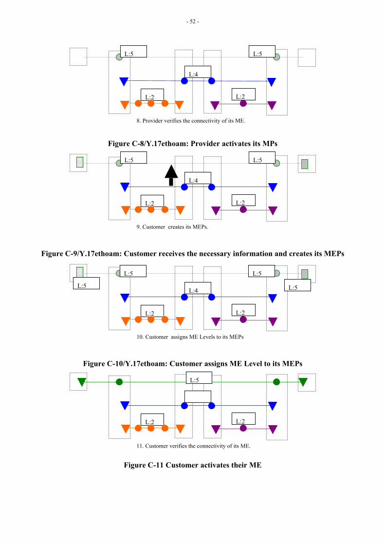
- 52 -
Figure C-8/Y.17ethoam: Provider activates its MPs
Figure C-9/Y.17ethoam: Customer receives the necessary information and creates its MEPs
Figure C-10/Y.17ethoam: Customer assigns ME Level to its MEPs
Figure C-11 Customer activates their ME
L:2 L:2
10. Customer assigns ME Levels to its MEPs
L:4L:5 L:5
L:2 L:2
11. Customer verifies the connectivity of its ME.
L:5
L:2 L:2
9. Customer creates its MEPs.
L:4
L:5 L:5
L:2 L:2
8. Provider verifies the connectivity of its ME.
L:4
L:5 L:5
L:5 L:5

- 53 -
C.3 Provisioning Example via Network Management System (NMS) A number of network operators deploy Ethernet (layer) networks without the in-band Ethernet control plane. Instead those networks deploy network management systems to provide ETH connection management functionality. In this way loop-free p2p and mp ETH connections can be set up in a single step, of which the result can be compared with a “per VLAN spanning tree”.
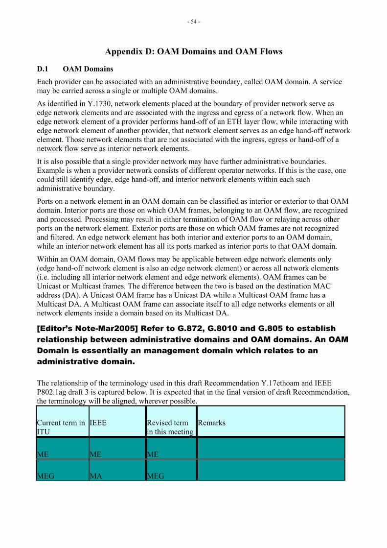
- 54 -
Appendix D: OAM Domains and OAM Flows
D.1 OAM Domains Each provider can be associated with an administrative boundary, called OAM domain. A service may be carried across a single or multiple OAM domains.
As identified in Y.1730, network elements placed at the boundary of provider network serve as edge network elements and are associated with the ingress and egress of a network flow. When an edge network element of a provider performs hand-off of an ETH layer flow, while interacting with edge network element of another provider, that network element serves as an edge hand-off network element. Those network elements that are not associated with the ingress, egress or hand-off of a network flow serve as interior network elements.
It is also possible that a single provider network may have further administrative boundaries. Example is when a provider network consists of different operator networks. If this is the case, one could still identify edge, edge hand-off, and interior network elements within each such administrative boundary.
Ports on a network element in an OAM domain can be classified as interior or exterior to that OAM domain. Interior ports are those on which OAM frames, belonging to an OAM flow, are recognized and processed. Processing may result in either termination of OAM flow or relaying across other ports on the network element. Exterior ports are those on which OAM frames are not recognized and filtered. An edge network element has both interior and exterior ports to an OAM domain, while an interior network element has all its ports marked as interior ports to that OAM domain.
Within an OAM domain, OAM flows may be applicable between edge network elements only (edge hand-off network element is also an edge network element) or across all network elements (i.e. including all interior network element and edge network elements). OAM frames can be Unicast or Multicast frames. The difference between the two is based on the destination MAC address (DA). A Unicast OAM frame has a Unicast DA while a Multicast OAM frame has a Multicast DA. A Multicast OAM frame can associate itself to all edge networks elements or all network elements inside a domain based on its Multicast DA.
[Editor’s Note-Mar2005] Refer to G.872, G.8010 and G.805 to establish relationship between administrative domains and OAM domains. An OAM Domain is essentially an management domain which relates to an administrative domain.
The relationship of the terminology used in this draft Recommendation Y.17ethoam and IEEE P802.1ag draft 3 is captured below. It is expected that in the final version of draft Recommendation, the terminology will be aligned, wherever possible.
Current term in ITU
IEEE Revised term in this meeting
Remarks
ME ME ME
MEG MA MEG
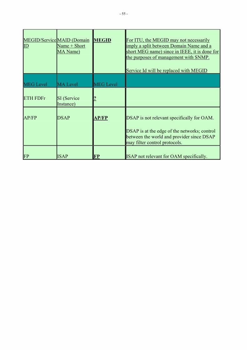
- 55 -
MEGID/Service ID
MAID (Domain Name + Short MA Name)
MEGID For ITU, the MEGID may not necessarily imply a split between Domain Name and a short MEG name) since in IEEE, it is done for the purposes of management with SNMP.
Service Id will be replaced with MEGID
MEG Level MA Level MEG Level
ETH FDFr SI (Service Instance)
?
AP/FP DSAP AP/FP DSAP is not relevant specifically for OAM.
DSAP is at the edge of the networks; control between the world and provider since DSAP may filter control protocols.
FP ISAP FP ISAP not relevant for OAM specifically.
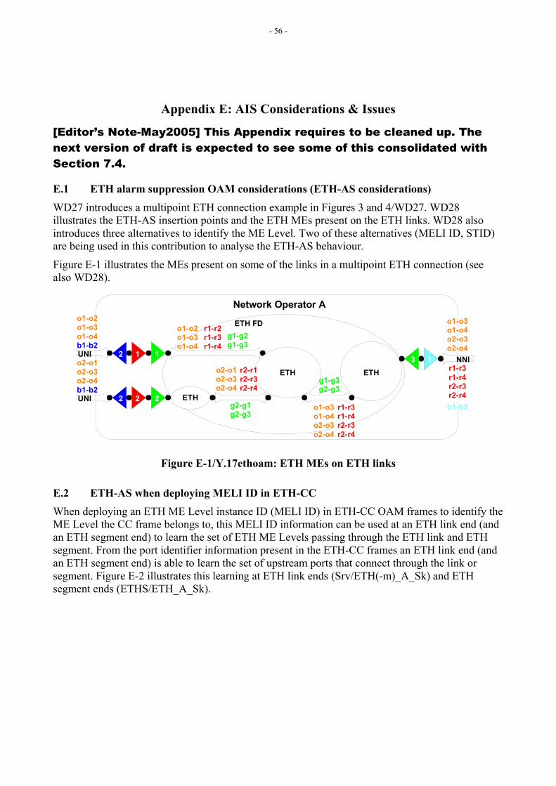
- 56 -
Appendix E: AIS Considerations & Issues
[Editor’s Note-May2005] This Appendix requires to be cleaned up. The next version of draft is expected to see some of this consolidated with Section 7.4.
E.1 ETH alarm suppression OAM considerations (ETH-AS considerations) WD27 introduces a multipoint ETH connection example in Figures 3 and 4/WD27. WD28 illustrates the ETH-AS insertion points and the ETH MEs present on the ETH links. WD28 also introduces three alternatives to identify the ME Level. Two of these alternatives (MELI ID, STID) are being used in this contribution to analyse the ETH-AS behaviour.
Figure E-1 illustrates the MEs present on some of the links in a multipoint ETH connection (see also WD28).
ETH ETH
ETH
NNI
UNI
UNI
ETH FD
Network Operator A
1 1
2 2
3 12
2
o1-o2o1-o3o1-o4
r1-r2r1-r3r1-r4
g1-g2g1-g3
o1-o2o1-o3o1-o4b1-b2
o2-o1o2-o3o2-o4b1-b2
o2-o1o2-o3o2-o4
r2-r1r2-r3r2-r4
g2-g1g2-g3
o1-o3o1-o4o2-o3o2-o4
r1-r3r1-r4r2-r3r2-r4
g1-g3g2-g3
o1-o3o1-o4o2-o3o2-o4
r1-r3r1-r4r2-r3r2-r4b1-b2
Figure E-1/Y.17ethoam: ETH MEs on ETH links
E.2 ETH-AS when deploying MELI ID in ETH-CC When deploying an ETH ME Level instance ID (MELI ID) in ETH-CC OAM frames to identify the ME Level the CC frame belongs to, this MELI ID information can be used at an ETH link end (and an ETH segment end) to learn the set of ETH ME Levels passing through the ETH link and ETH segment. From the port identifier information present in the ETH-CC frames an ETH link end (and an ETH segment end) is able to learn the set of upstream ports that connect through the link or segment. Figure E-2 illustrates this learning at ETH link ends (Srv/ETH(-m)_A_Sk) and ETH segment ends (ETHS/ETH_A_Sk).
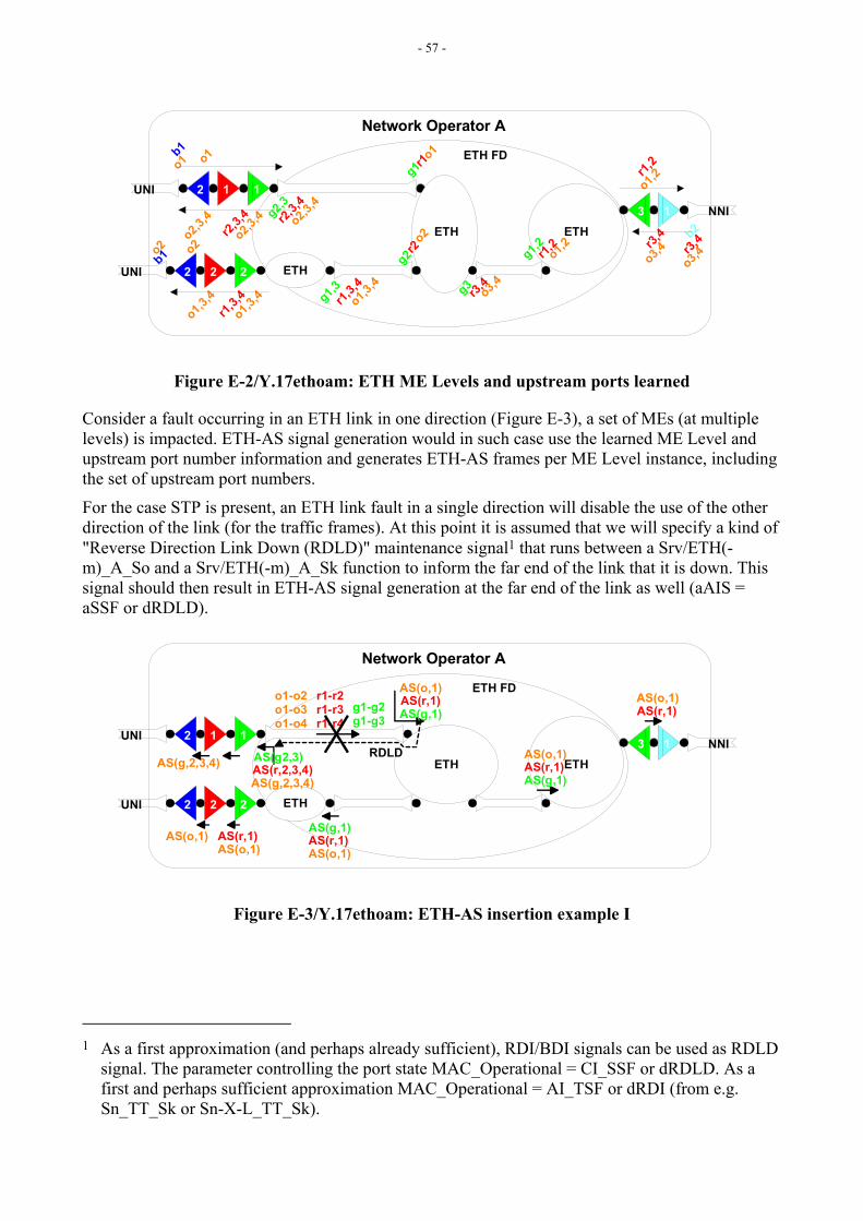
- 57 -
ETH ETH
ETH
NNI
UNI
UNI
ETH FD
Network Operator A
1 1
2 2
3 1
2
2
o1
o2 o2r2
g2
o3,4
r1,3,4
g3
o3,4r3,
4o2,3,4
o1
o2,3,4 g2,3
r2,3,4o2,3
,4
r2,3,4
g1r1o1
o1,3,4
r1,3,4g1,3
g1,2
o1,3,4
o1,3,4
o1,2
r3,4
r1,2
r1,2
o1,2
b2
b1o3,4r3,
4
b1
o2
Figure E-2/Y.17ethoam: ETH ME Levels and upstream ports learned
Consider a fault occurring in an ETH link in one direction (Figure E-3), a set of MEs (at multiple levels) is impacted. ETH-AS signal generation would in such case use the learned ME Level and upstream port number information and generates ETH-AS frames per ME Level instance, including the set of upstream port numbers.
For the case STP is present, an ETH link fault in a single direction will disable the use of the other direction of the link (for the traffic frames). At this point it is assumed that we will specify a kind of "Reverse Direction Link Down (RDLD)" maintenance signal1 that runs between a Srv/ETH(-m)_A_So and a Srv/ETH(-m)_A_Sk function to inform the far end of the link that it is down. This signal should then result in ETH-AS signal generation at the far end of the link as well (aAIS = aSSF or dRDLD).
ETH ETH
ETH
NNI
UNI
UNI
ETH FD
Network Operator A
1 1
2 2
3 12
2
o1-o2o1-o3o1-o4
r1-r2r1-r3r1-r4
g1-g2g1-g3 AS(g,1)
AS(r,1)AS(o,1)
AS(g,1)
AS(g,1)
AS(r,1)AS(r,1)
AS(r,1)
AS(r,1)
AS(o,1)AS(o,1)AS(o,1)
AS(o,1)
AS(o,1)
RDLD
AS(g,2,3,4)AS(r,2,3,4)AS(g2,3)AS(g,2,3,4)
Figure E-3/Y.17ethoam: ETH-AS insertion example I
1 As a first approximation (and perhaps already sufficient), RDI/BDI signals can be used as RDLD
signal. The parameter controlling the port state MAC_Operational = CI_SSF or dRDLD. As a first and perhaps sufficient approximation MAC_Operational = AI_TSF or dRDI (from e.g. Sn_TT_Sk or Sn-X-L_TT_Sk).
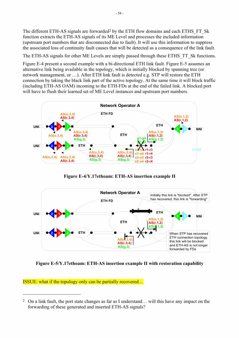
- 58 -
The different ETH-AS signals are forwarded2 by the ETH flow domains and each ETHS_FT_Sk function extracts the ETH-AS signals of its ME Level and processes the included information (upstream port numbers that are disconnected due to fault). It will use this information to suppress the associated loss of continuity fault causes that will be detected as a consequence of the link fault.
The ETH-AS signals for other ME Levels are simply passed through these ETHS_TT_Sk functions.
Figure E-4 present a second example with a bi-directional ETH link fault. Figure E-5 assumes an alternative link being available in the topology, which is initially blocked by spanning tree (or network management, or …). After ETH link fault is detected e.g. STP will restore the ETH connection by taking the black link part of the active topology. At the same time it will block traffic (including ETH-AS OAM) incoming to the ETH-FDs at the end of the failed link. A blocked port will have to flush their learned set of ME Level instances and upstream port numbers.
ETH
ETH
ETH
NNI
UNI
UNI
ETH FD
Network Operator A
1 1
2 2
3 12
2o1-o3o1-o4o2-o3o2-o4
r1-r3r1-r4r2-r3r2-r4
g1-g3g2-g3
b1-b2
AS(g,1,2)AS(r,1,2)AS(o,1,2)
AS(g,3)AS(r,3,4)AS(o,3,4)
AS(g,3)AS(r,3,4)AS(o,3,4)
AS(g,3)AS(r,3,4)AS(o,3,4)
AS(r,3,4)AS(o,3,4)
AS(o,3,4)
AS(r,3,4)AS(o,3,4)AS(o,3,4)
AS(r,1,2)AS(o,1,2)
Figure E-4/Y.17ethoam: ETH-AS insertion example II
ETH
ETH
ETH
NNI
UNI
UNI
ETH FD
Network Operator A
1 1
2 2
3 12
2b1-b2
AS(g,1,2)AS(r,1,2)AS(o,1,2)
AS(g,3)AS(r,3,4)AS(o,3,4)
Initially this link is "blocked". After STPhas recovered, this link is "forwarding"
When STP has recoveredETH connection topology,this link will be blockedand ETH-AS is not longerforwarded by FDs
Figure E-5/Y.17ethoam: ETH-AS insertion example II with restoration capability
ISSUE: what if the topology only can be partially recovered…
2 On a link fault, the port state changes as far as I understand… will this have any impact on the
forwarding of these generated and inserted ETH-AS signals?
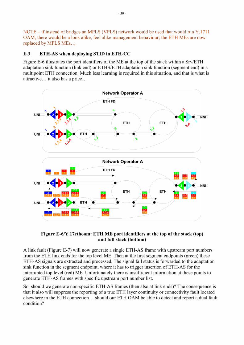
- 59 -
NOTE – if instead of bridges an MPLS (VPLS) network would be used that would run Y.1711 OAM, there would be a look alike, feel alike management behaviour; the ETH MEs are now replaced by MPLS MEs…
E.3 ETH-AS when deploying STID in ETH-CC Figure E-6 illustrates the port identifiers of the ME at the top of the stack within a Srv/ETH adaptation sink function (link end) or ETHS/ETH adaptation sink function (segment end) in a multipoint ETH connection. Much less learning is required in this situation, and that is what is attractive… it also has a price…
ETH ETH
ETH
NNI
UNI
UNI
ETH FD
Network Operator A
1 1
2 2
3 12
2
2,3,4
2,3,4 2,3
1
2
1,3,4
2
1,2
3
3,42
11
1,3
1,3,4
1 1,2
ETH ETH
ETH
NNI
UNI
UNI
ETH FD
Network Operator A
1 1
2 2
3 12
2
11
1 111
11
2,3,42,3,42,3
2,3,42,3,42,3
2,3,42,3,422,3
1,3,41,3,41,3
1,3,41,3,42,3
1,3,41,3,42
1,3,41,3,41,3
222
1,21,21,2
3,43,43
1,21,21,2
1,21,2
3,43,4
3,43,43
3,43,42
1,21,2
Figure E-6/Y.17ethoam: ETH ME port identifiers at the top of the stack (top) and full stack (bottom)
A link fault (Figure E-7) will now generate a single ETH-AS frame with upstream port numbers from the ETH link ends for the top level ME. Then at the first segment endpoints (green) these ETH-AS signals are extracted and processed. The signal fail status is forwarded to the adaptation sink function in the segment endpoint, where it has to trigger insertion of ETH-AS for the interrupted top level (red) ME. Unfortunately there is insufficient information at these points to generate ETH-AS frames with specific upstream port number list.
So, should we generate non-specific ETH-AS frames (then also at link ends)? The consequence is that it also will suppress the reporting of a true ETH layer continuity or connectivity fault located elsewhere in the ETH connection… should our ETH OAM be able to detect and report a dual fault condition?
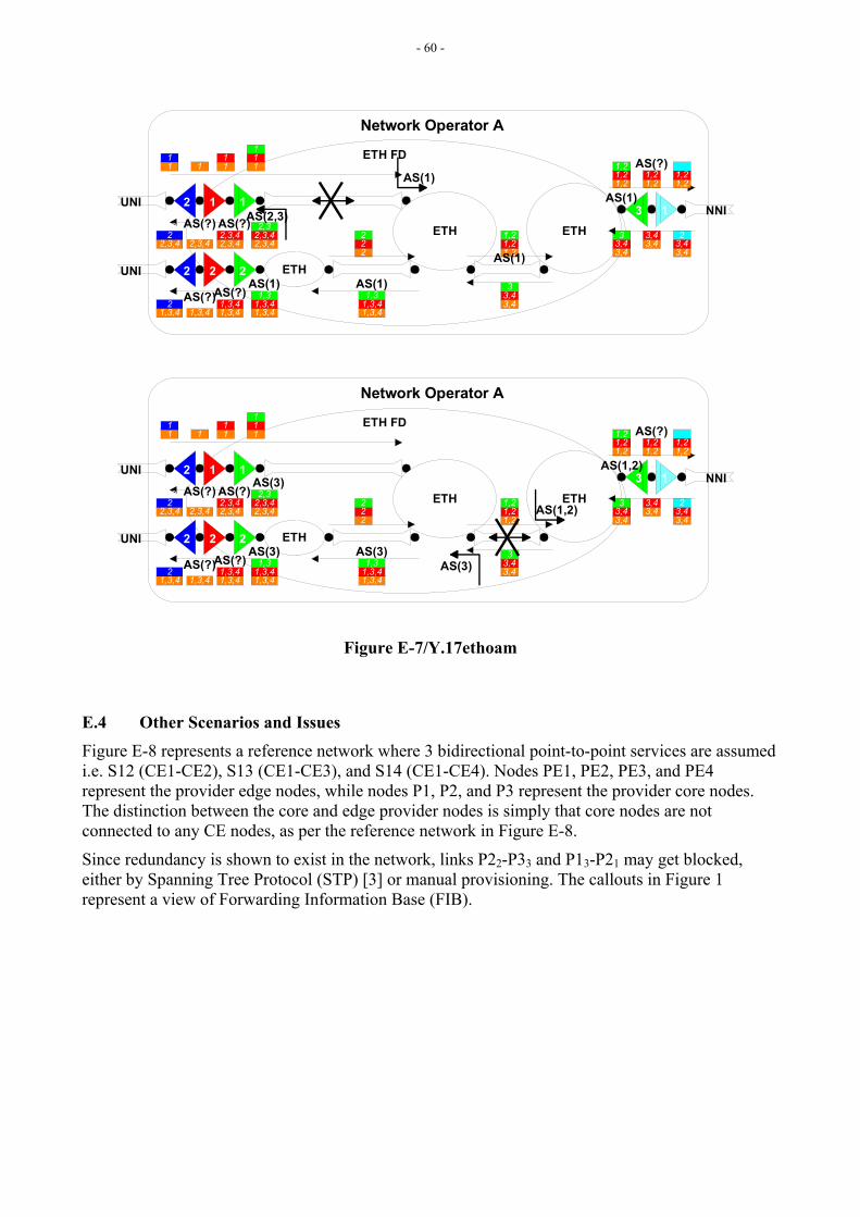
- 60 -
ETH ETH
ETH
NNI
UNI
UNI
ETH FD
Network Operator A
1 1
2 2
3 12
2
11
1 111
11
2,3,42,3,42,3
2,3,42,3,42,3
2,3,42,3,422,3
1,3,41,3,41,3
1,3,41,3,42,3
1,3,41,3,42
1,3,41,3,41,3
222
1,21,21,2
3,43,43
1,21,21,2
1,21,2
3,43,4
3,43,43
3,43,42
1,21,2
AS(2,3)
AS(1)
AS(?)
AS(1)
AS(1)
AS(?)
AS(1)
AS(1)
AS(?)
AS(?)
AS(?)
ETH ETH
ETH
NNI
UNI
UNI
ETH FD
Network Operator A
1 1
2 2
3 12
2
11
1 111
11
2,3,42,3,42,3
2,3,42,3,42,3
2,3,42,3,422,3
1,3,41,3,41,3
1,3,41,3,42,3
1,3,41,3,42
1,3,41,3,41,3
222
1,21,21,2
3,43,43
1,21,21,2
1,21,2
3,43,4
3,43,43
3,43,42
1,21,2
AS(3)
AS(1,2)AS(?)
AS(3)
AS(1,2)
AS(?)
AS(3)
AS(3)
AS(?)
AS(?)
AS(?)
Figure E-7/Y.17ethoam
E.4 Other Scenarios and Issues Figure E-8 represents a reference network where 3 bidirectional point-to-point services are assumed i.e. S12 (CE1-CE2), S13 (CE1-CE3), and S14 (CE1-CE4). Nodes PE1, PE2, PE3, and PE4 represent the provider edge nodes, while nodes P1, P2, and P3 represent the provider core nodes. The distinction between the core and edge provider nodes is simply that core nodes are not connected to any CE nodes, as per the reference network in Figure E-8.
Since redundancy is shown to exist in the network, links P22-P33 and P13-P21 may get blocked, either by Spanning Tree Protocol (STP) [3] or manual provisioning. The callouts in Figure 1 represent a view of Forwarding Information Base (FIB).
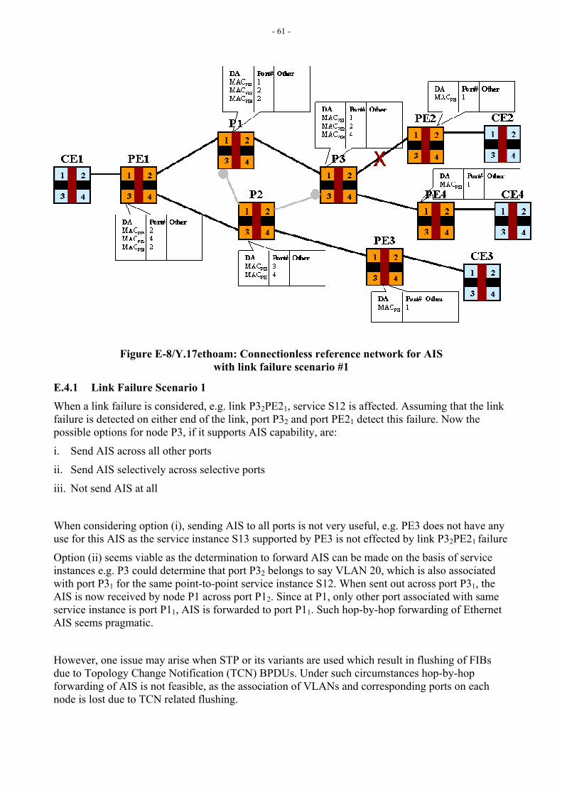
- 61 -
Figure E-8/Y.17ethoam: Connectionless reference network for AIS with link failure scenario #1
E.4.1 Link Failure Scenario 1 When a link failure is considered, e.g. link P32PE21, service S12 is affected. Assuming that the link failure is detected on either end of the link, port P32 and port PE21 detect this failure. Now the possible options for node P3, if it supports AIS capability, are:
i. Send AIS across all other ports
ii. Send AIS selectively across selective ports
iii. Not send AIS at all
When considering option (i), sending AIS to all ports is not very useful, e.g. PE3 does not have any use for this AIS as the service instance S13 supported by PE3 is not effected by link P32PE21 failure
Option (ii) seems viable as the determination to forward AIS can be made on the basis of service instances e.g. P3 could determine that port P32 belongs to say VLAN 20, which is also associated with port P31 for the same point-to-point service instance S12. When sent out across port P31, the AIS is now received by node P1 across port P12. Since at P1, only other port associated with same service instance is port P11, AIS is forwarded to port P11. Such hop-by-hop forwarding of Ethernet AIS seems pragmatic.
However, one issue may arise when STP or its variants are used which result in flushing of FIBs due to Topology Change Notification (TCN) BPDUs. Under such circumstances hop-by-hop forwarding of AIS is not feasible, as the association of VLANs and corresponding ports on each node is lost due to TCN related flushing.
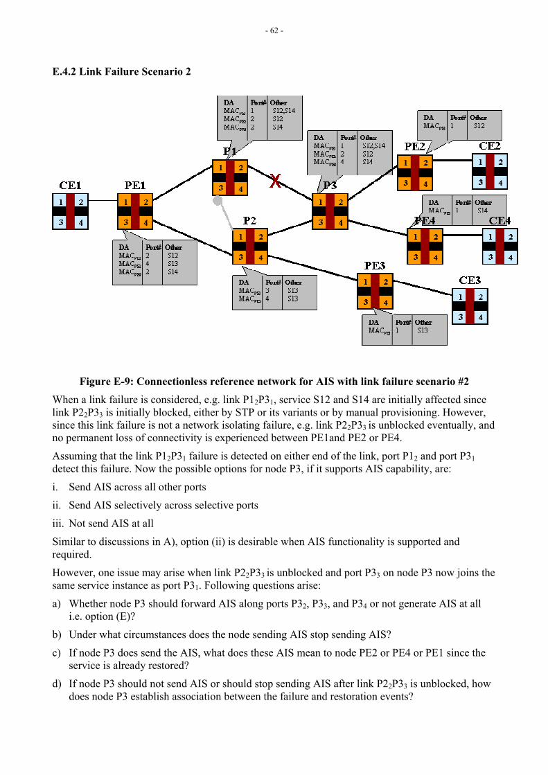
- 62 -
E.4.2 Link Failure Scenario 2
Figure E-9: Connectionless reference network for AIS with link failure scenario #2 When a link failure is considered, e.g. link P12P31, service S12 and S14 are initially affected since link P22P33 is initially blocked, either by STP or its variants or by manual provisioning. However, since this link failure is not a network isolating failure, e.g. link P22P33 is unblocked eventually, and no permanent loss of connectivity is experienced between PE1and PE2 or PE4.
Assuming that the link P12P31 failure is detected on either end of the link, port P12 and port P31 detect this failure. Now the possible options for node P3, if it supports AIS capability, are:
i. Send AIS across all other ports
ii. Send AIS selectively across selective ports
iii. Not send AIS at all
Similar to discussions in A), option (ii) is desirable when AIS functionality is supported and required.
However, one issue may arise when link P22P33 is unblocked and port P33 on node P3 now joins the same service instance as port P31. Following questions arise:
a) Whether node P3 should forward AIS along ports P32, P33, and P34 or not generate AIS at all i.e. option (E)?
b) Under what circumstances does the node sending AIS stop sending AIS?
c) If node P3 does send the AIS, what does these AIS mean to node PE2 or PE4 or PE1 since the service is already restored?
d) If node P3 should not send AIS or should stop sending AIS after link P22P33 is unblocked, how does node P3 establish association between the failure and restoration events?
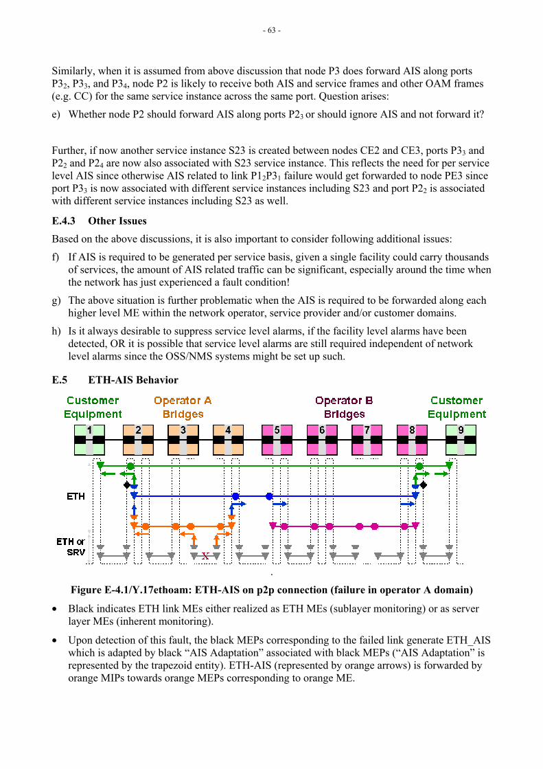
- 63 -
Similarly, when it is assumed from above discussion that node P3 does forward AIS along ports P32, P33, and P34, node P2 is likely to receive both AIS and service frames and other OAM frames (e.g. CC) for the same service instance across the same port. Question arises:
e) Whether node P2 should forward AIS along ports P23 or should ignore AIS and not forward it?
Further, if now another service instance S23 is created between nodes CE2 and CE3, ports P33 and P22 and P24 are now also associated with S23 service instance. This reflects the need for per service level AIS since otherwise AIS related to link P12P31 failure would get forwarded to node PE3 since port P33 is now associated with different service instances including S23 and port P22 is associated with different service instances including S23 as well.
E.4.3 Other Issues Based on the above discussions, it is also important to consider following additional issues:
f) If AIS is required to be generated per service basis, given a single facility could carry thousands of services, the amount of AIS related traffic can be significant, especially around the time when the network has just experienced a fault condition!
g) The above situation is further problematic when the AIS is required to be forwarded along each higher level ME within the network operator, service provider and/or customer domains.
h) Is it always desirable to suppress service level alarms, if the facility level alarms have been detected, OR it is possible that service level alarms are still required independent of network level alarms since the OSS/NMS systems might be set up such.
E.5 ETH-AIS Behavior
.
Figure E-4.1/Y.17ethoam: ETH-AIS on p2p connection (failure in operator A domain)
• Black indicates ETH link MEs either realized as ETH MEs (sublayer monitoring) or as server layer MEs (inherent monitoring).
• Upon detection of this fault, the black MEPs corresponding to the failed link generate ETH_AIS which is adapted by black “AIS Adaptation” associated with black MEPs (“AIS Adaptation” is represented by the trapezoid entity). ETH-AIS (represented by orange arrows) is forwarded by orange MIPs towards orange MEPs corresponding to orange ME.
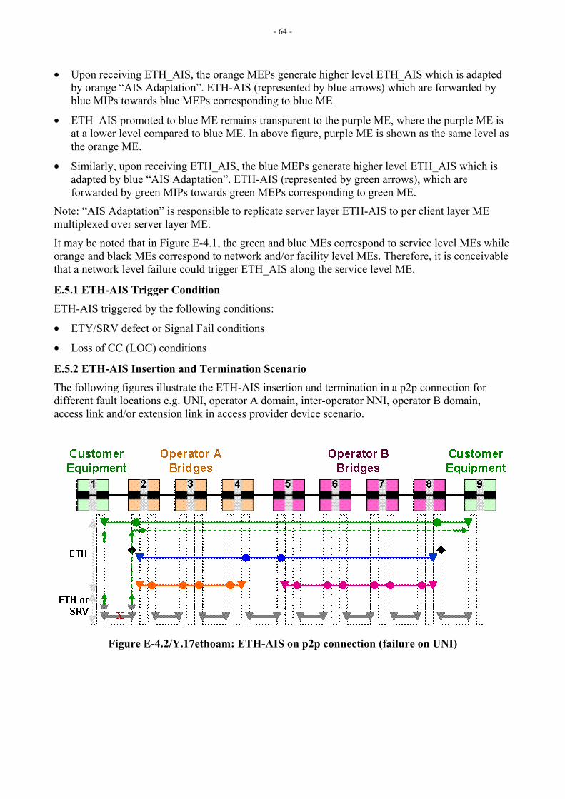
- 64 -
• Upon receiving ETH_AIS, the orange MEPs generate higher level ETH_AIS which is adapted by orange “AIS Adaptation”. ETH-AIS (represented by blue arrows) which are forwarded by blue MIPs towards blue MEPs corresponding to blue ME.
• ETH_AIS promoted to blue ME remains transparent to the purple ME, where the purple ME is at a lower level compared to blue ME. In above figure, purple ME is shown as the same level as the orange ME.
• Similarly, upon receiving ETH_AIS, the blue MEPs generate higher level ETH_AIS which is adapted by blue “AIS Adaptation”. ETH-AIS (represented by green arrows), which are forwarded by green MIPs towards green MEPs corresponding to green ME.
Note: “AIS Adaptation” is responsible to replicate server layer ETH-AIS to per client layer ME multiplexed over server layer ME.
It may be noted that in Figure E-4.1, the green and blue MEs correspond to service level MEs while orange and black MEs correspond to network and/or facility level MEs. Therefore, it is conceivable that a network level failure could trigger ETH_AIS along the service level ME.
E.5.1 ETH-AIS Trigger Condition ETH-AIS triggered by the following conditions:
• ETY/SRV defect or Signal Fail conditions
• Loss of CC (LOC) conditions
E.5.2 ETH-AIS Insertion and Termination Scenario The following figures illustrate the ETH-AIS insertion and termination in a p2p connection for different fault locations e.g. UNI, operator A domain, inter-operator NNI, operator B domain, access link and/or extension link in access provider device scenario.
Figure E-4.2/Y.17ethoam: ETH-AIS on p2p connection (failure on UNI)
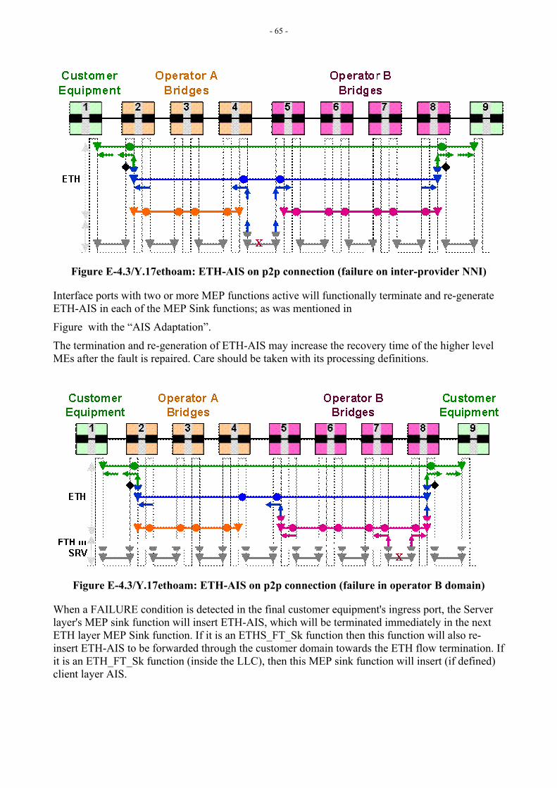
- 65 -
Figure E-4.3/Y.17ethoam: ETH-AIS on p2p connection (failure on inter-provider NNI)
Interface ports with two or more MEP functions active will functionally terminate and re-generate ETH-AIS in each of the MEP Sink functions; as was mentioned in
Figure with the “AIS Adaptation”.
The termination and re-generation of ETH-AIS may increase the recovery time of the higher level MEs after the fault is repaired. Care should be taken with its processing definitions.
Figure E-4.3/Y.17ethoam: ETH-AIS on p2p connection (failure in operator B domain)
When a FAILURE condition is detected in the final customer equipment's ingress port, the Server layer's MEP sink function will insert ETH-AIS, which will be terminated immediately in the next ETH layer MEP Sink function. If it is an ETHS_FT_Sk function then this function will also re-insert ETH-AIS to be forwarded through the customer domain towards the ETH flow termination. If it is an ETH_FT_Sk function (inside the LLC), then this MEP sink function will insert (if defined) client layer AIS.
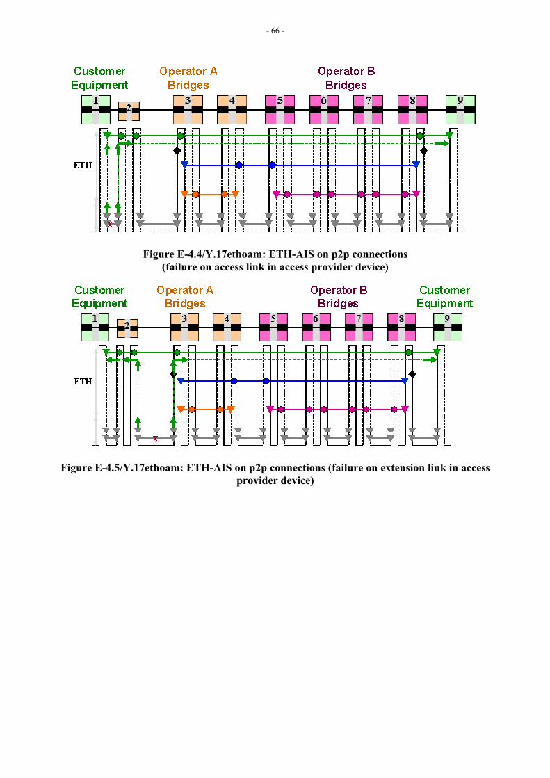
- 66 -
Figure E-4.4/Y.17ethoam: ETH-AIS on p2p connections (failure on access link in access provider device)
Figure E-4.5/Y.17ethoam: ETH-AIS on p2p connections (failure on extension link in access provider device)
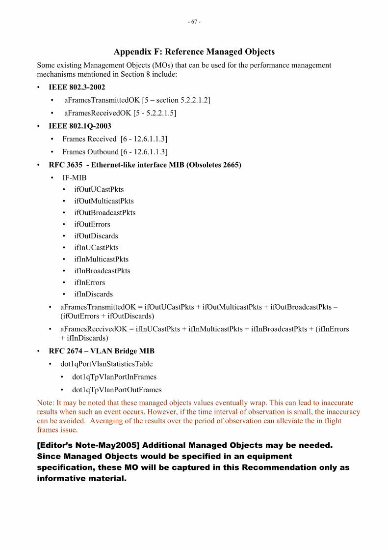
- 67 -
Appendix F: Reference Managed Objects Some existing Management Objects (MOs) that can be used for the performance management mechanisms mentioned in Section 8 include:
• IEEE 802.3-2002 • aFramesTransmittedOK [5 – section 5.2.2.1.2]
• aFramesReceivedOK [5 - 5.2.2.1.5]
• IEEE 802.1Q-2003 • Frames Received [6 - 12.6.1.1.3]
• Frames Outbound [6 - 12.6.1.1.3]
• RFC 3635 - Ethernet-like interface MIB (Obsoletes 2665) • IF-MIB
• ifOutUCastPkts • ifOutMulticastPkts • ifOutBroadcastPkts • ifOutErrors • ifOutDiscards • ifInUCastPkts • ifInMulticastPkts • ifInBroadcastPkts • ifInErrors • ifInDiscards
• aFramesTransmittedOK = ifOutUCastPkts + ifOutMulticastPkts + ifOutBroadcastPkts – (ifOutErrors + ifOutDiscards)
• aFramesReceivedOK = ifInUCastPkts + ifInMulticastPkts + ifInBroadcastPkts + (ifInErrors + ifInDiscards)
• RFC 2674 – VLAN Bridge MIB
• dot1qPortVlanStatisticsTable
• dot1qTpVlanPortInFrames
• dot1qTpVlanPortOutFrames
Note: It may be noted that these managed objects values eventually wrap. This can lead to inaccurate results when such an event occurs. However, if the time interval of observation is small, the inaccuracy can be avoided. Averaging of the results over the period of observation can alleviate the in flight frames issue.
[Editor’s Note-May2005] Additional Managed Objects may be needed. Since Managed Objects would be specified in an equipment specification, these MO will be captured in this Recommendation only as informative material.

- 68 -
Appendix G: Frame Loss Measurement
G.1 Frame Loss Measurement Mechanisms Different measurement mechanisms are possible to perform performance measurements. One significant difference across these mechanisms is the level of accuracy of measurements. These mechanisms include:
• Management plane statistical methods Statistical methods use OAM frames to estimate data path behavior. Such methods are least accurate since they apply approximation to emulate data frames. The limitation lies in that the behavior of actual data frames may be quite different due to different addressing, processing, transient congestion conditions etc. Also, error conditions in networks typically happens in bursts thus statistical methods can likely miss those bursts and represent different results.
• Management plane managed objects Here OAM frames use data path managed objects to calculate performance parameters and are inserted and/or extracted via management plane. These methods are fairly accurate since they use data path statistics to measure data path performance. Their limitation lies in that since the insertion and extraction of these OAM frames is done via management plane, in-flight frames need to be accounted for. On the egress side of OAM frame, in-flight frames refers to data frames between accessing egress data path managed objects and actual transmission of OAM frame. On ingress side of OAM frame, in-flight frames refer to data frames between reception of OAM frame and subsequent accessing of ingress data plane managed objects. However, this limitation can be addressed by averaging such measurements across multiple time intervals.
• Data path OAM frames OAM frames use data path managed objects and are inserted and/or extracted via data plane. This method tends to be most accurate since it does not have the limitation associated with the in-flight frames. However, the current data path hardware/chips do not support the implementation of such methods since this requires Ethernet data path processing to include automatic insertion and/or extraction of OAM frames with data plane managed object values. Moreover, it would also require changes in hardware/chips to allow ingress and egress filtering rules across OAM frames to protect service provider administrative domains from unintended OAM frames.
Of the three methods mentioned to measure performance the use of management plane managed objects mechanism seems to be the most suitable. The advantage of these mechanisms is that these require no changes in the existing hardware/chips and only require change in OAM client software that needs to be implemented. The steps involved in such measurement mechanism include:
• Collection of managed object (s) information
• Calculation of performance parameter (s)
G.1.1 Performance Management Collection Method
To collect managed object information, general or specific methods can be used. When a generic method is used, it can be applied to collect information across different managed objects e.g. using TLVs as information elements instead of specific information elements. However, when specific method with specific information elements is used, a separate method is needed per managed object or per set of managed objects.
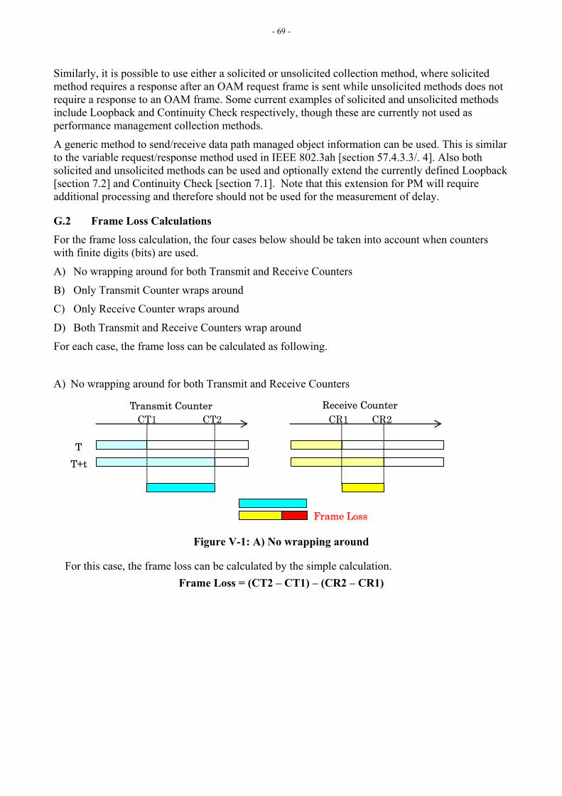
- 69 -
Similarly, it is possible to use either a solicited or unsolicited collection method, where solicited method requires a response after an OAM request frame is sent while unsolicited methods does not require a response to an OAM frame. Some current examples of solicited and unsolicited methods include Loopback and Continuity Check respectively, though these are currently not used as performance management collection methods.
A generic method to send/receive data path managed object information can be used. This is similar to the variable request/response method used in IEEE 802.3ah [section 57.4.3.3/. 4]. Also both solicited and unsolicited methods can be used and optionally extend the currently defined Loopback [section 7.2] and Continuity Check [section 7.1]. Note that this extension for PM will require additional processing and therefore should not be used for the measurement of delay.
G.2 Frame Loss Calculations For the frame loss calculation, the four cases below should be taken into account when counters with finite digits (bits) are used.
A) No wrapping around for both Transmit and Receive Counters
B) Only Transmit Counter wraps around
C) Only Receive Counter wraps around
D) Both Transmit and Receive Counters wrap around
For each case, the frame loss can be calculated as following.
A) No wrapping around for both Transmit and Receive Counters
CT1 CT2 CR1 CR2
Transmit Counter Receive Counter
T T+t
Frame Loss
Figure V-1: A) No wrapping around
For this case, the frame loss can be calculated by the simple calculation. Frame Loss = (CT2 – CT1) – (CR2 – CR1)
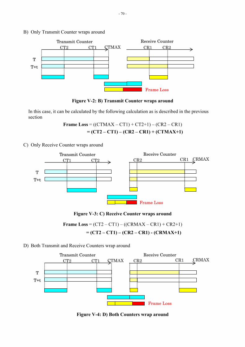
- 70 -
B) Only Transmit Counter wraps around
CT2 CT1 CR1 CR2
Transmit Counter Receive Counter
T T+t
Frame Loss
CTMAX
Figure V-2: B) Transmit Counter wraps around
In this case, it can be calculated by the following calculation as is described in the previous section
Frame Loss = ((CTMAX – CT1) + CT2+1) – (CR2 – CR1) = (CT2 – CT1) – (CR2 – CR1) + (CTMAX+1)
C) Only Receive Counter wraps around
CT1 CT2 CR1 CR2
Transmit Counter Receive Counter
T T+t
Frame Loss
CRMAX
Figure V-3: C) Receive Counter wraps around
Frame Loss = (CT2 – CT1) – ((CRMAX – CR1) + CR2+1)
= (CT2 – CT1) – (CR2 – CR1) - (CRMAX+1)
D) Both Transmit and Receive Counters wrap around
CR1 CR2
Receive Counter
Frame Loss
CRMAXCT2 CT1 Transmit Counter
T T+t
CTMAX
Figure V-4: D) Both Counters wrap around

- 71 -
Frame Loss = ((CTMAX – CT1)+CT2+1) – ((CRMAX – CR1) + CR2+1)
= (CT2 – CT1) – (CR2 – CR1) + (CTMAX+1) - (CRMAX+1)
G.2.1 Simplified calculation for Frame Loss If the calculation is processed in unsigned value schema, the calculation formula for the frame loss can be greatly simplified by the following characteristics.
N+(MAX+1) ≡N mod(MAX+1)
N-(MAX+1) ≡ N mod(MAX+1)
Therefore each calculation formulas for frame loss which are described in the section 8.2.3 and 8.2.4 can be transformed as below.
A) Frame Loss = (CT2 - CT1) - (CR2 - CR1) B) Frame Loss = (CT2 – CT1) – (CR2 – CR1) + CTMAX+1
= ((CT2 + (CTMAX+1)) – CT1) – (CR2 – CR1)
= (CT2 – CT1) – (CR2 – CR1) C) Frame Loss = (CT2 – CT1) – (CR2 – CR1) – (CRMAX+1)
= (CT2 – CT1) – ((CR2 + CRMAX+1) – CR1)
= (CT2 – CT1) – (CR2 – CR1) D) Frame Loss = (CT2 – CT1) – (CR2 – CR1) + (CTMAX+1) – (CRMAX+1)
= ((CT2 + (CTMAX+1)) – CT1) – ((CR2 + (CRMAX+1)) – CR1)
= (CT2 – CT1) – (CR2 – CR1) As described above, the frame loss can be calculated by the single calculation formula for any case if it is calculated in unsigned value schema.
If wrapping around of counters happen more than twice, the counters for the wrapping around are required to calculate the frame loss correctly.

- 72 -
Appendix H: ME Level and Multicast Address Relationship
[Editor’s Note-Mar2005] Intention was expressed to capture relationship between the ME Levels and Multicast DA applicable for some OAM Frame Types as informative material. Contributions are invited.
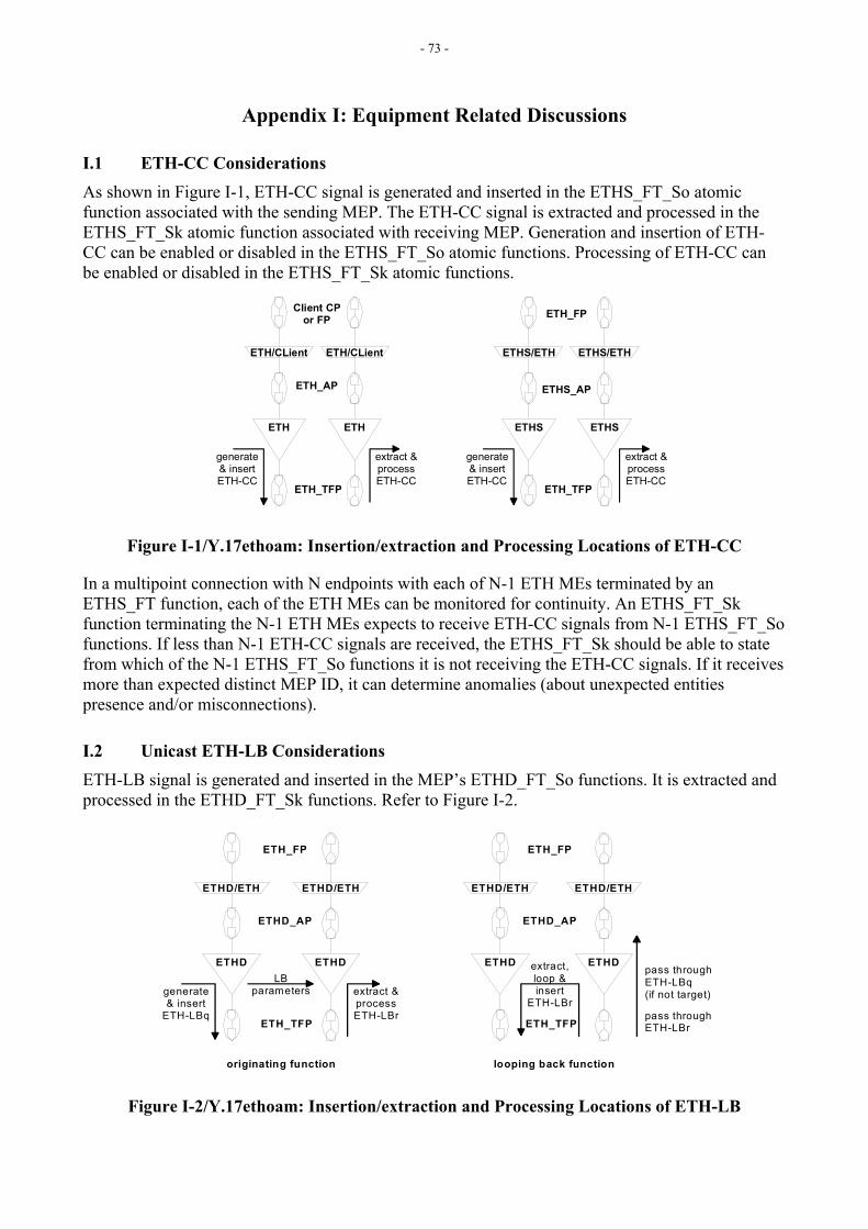
- 73 -
Appendix I: Equipment Related Discussions
I.1 ETH-CC Considerations As shown in Figure I-1, ETH-CC signal is generated and inserted in the ETHS_FT_So atomic function associated with the sending MEP. The ETH-CC signal is extracted and processed in the ETHS_FT_Sk atomic function associated with receiving MEP. Generation and insertion of ETH-CC can be enabled or disabled in the ETHS_FT_So atomic functions. Processing of ETH-CC can be enabled or disabled in the ETHS_FT_Sk atomic functions.
ETH_TFP
ETH_AP
ETH
ETH/CLient
Client CPor FP
ETH
ETH/CLient
generate& insertETH-CC
extract &processETH-CC
ETH_TFP
ETHS_AP
ETHS
ETHS/ETH
ETH_FP
ETHS
ETHS/ETH
generate& insertETH-CC
extract &processETH-CC
Figure I-1/Y.17ethoam: Insertion/extraction and Processing Locations of ETH-CC
In a multipoint connection with N endpoints with each of N-1 ETH MEs terminated by an ETHS_FT function, each of the ETH MEs can be monitored for continuity. An ETHS_FT_Sk function terminating the N-1 ETH MEs expects to receive ETH-CC signals from N-1 ETHS_FT_So functions. If less than N-1 ETH-CC signals are received, the ETHS_FT_Sk should be able to state from which of the N-1 ETHS_FT_So functions it is not receiving the ETH-CC signals. If it receives more than expected distinct MEP ID, it can determine anomalies (about unexpected entities presence and/or misconnections).
I.2 Unicast ETH-LB Considerations ETH-LB signal is generated and inserted in the MEP’s ETHD_FT_So functions. It is extracted and processed in the ETHD_FT_Sk functions. Refer to Figure I-2.
ETH_TFP
ETHD_AP
ETHD
ETHD/ETH
ETH_FP
ETHD
ETHD/ETH
generate& insert
ETH-LBq
extract &processETH-LBr
LBparameters
ETH_TFP
ETHD_AP
ETHD
ETHD/ETH
ETH_FP
ETHD
ETHD/ETH
pass throughETH-LBq(if not target)
extract,loop &insert
ETH-LBr
originating function looping back function
pass throughETH-LBr
Figure I-2/Y.17ethoam: Insertion/extraction and Processing Locations of ETH-LB
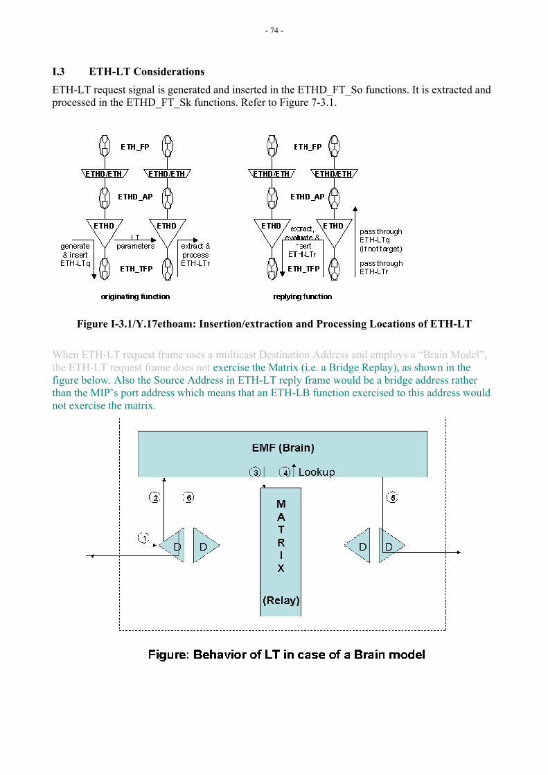
- 74 -
I.3 ETH-LT Considerations ETH-LT request signal is generated and inserted in the ETHD_FT_So functions. It is extracted and processed in the ETHD_FT_Sk functions. Refer to Figure 7-3.1.
Figure I-3.1/Y.17ethoam: Insertion/extraction and Processing Locations of ETH-LT When ETH-LT request frame uses a multicast Destination Address and employs a “Brain Model”, the ETH-LT request frame does not exercise the Matrix (i.e. a Bridge Replay), as shown in the figure below. Also the Source Address in ETH-LT reply frame would be a bridge address rather than the MIP’s port address which means that an ETH-LB function exercised to this address would not exercise the matrix.
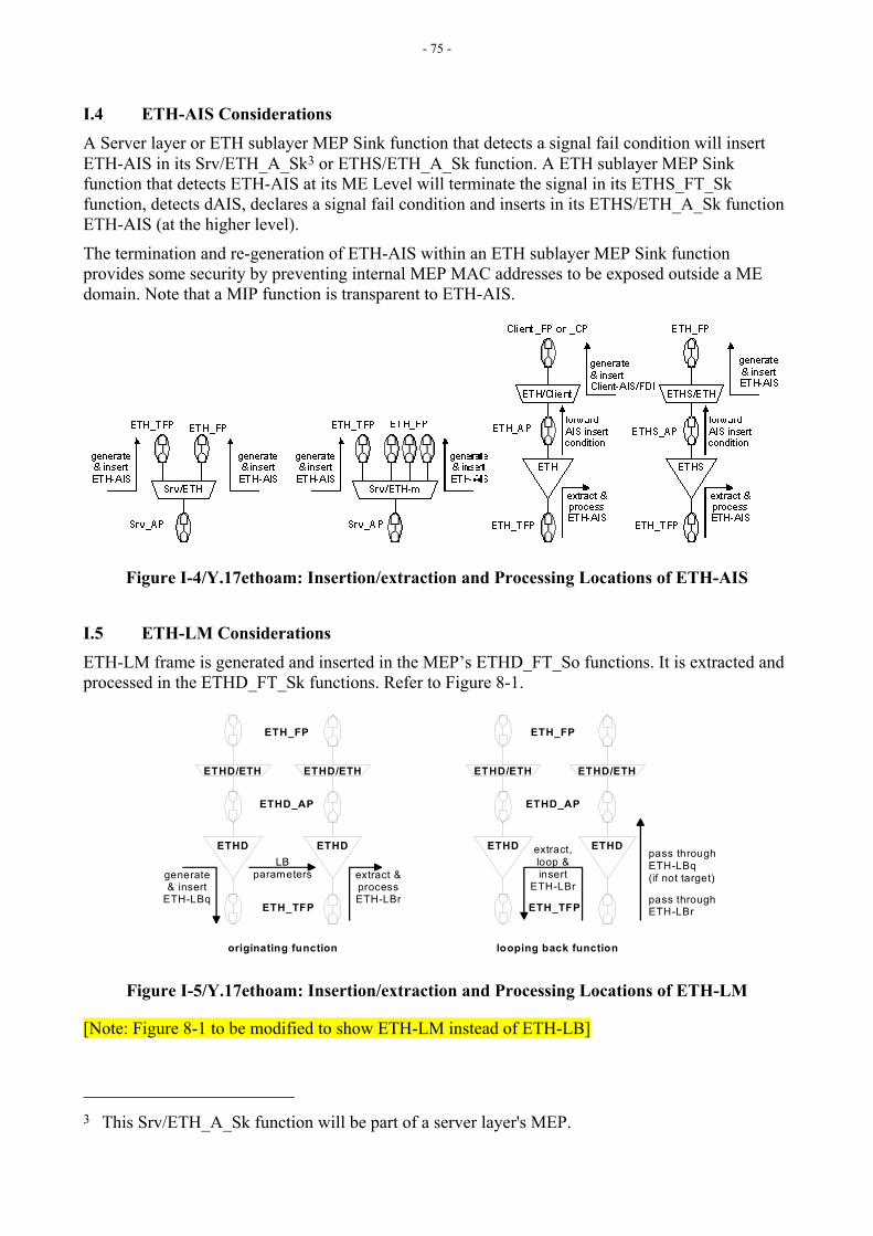
- 75 -
I.4 ETH-AIS Considerations A Server layer or ETH sublayer MEP Sink function that detects a signal fail condition will insert ETH-AIS in its Srv/ETH_A_Sk3 or ETHS/ETH_A_Sk function. A ETH sublayer MEP Sink function that detects ETH-AIS at its ME Level will terminate the signal in its ETHS_FT_Sk function, detects dAIS, declares a signal fail condition and inserts in its ETHS/ETH_A_Sk function ETH-AIS (at the higher level).
The termination and re-generation of ETH-AIS within an ETH sublayer MEP Sink function provides some security by preventing internal MEP MAC addresses to be exposed outside a ME domain. Note that a MIP function is transparent to ETH-AIS.
Figure I-4/Y.17ethoam: Insertion/extraction and Processing Locations of ETH-AIS
I.5 ETH-LM Considerations ETH-LM frame is generated and inserted in the MEP’s ETHD_FT_So functions. It is extracted and processed in the ETHD_FT_Sk functions. Refer to Figure 8-1.
ETH_TFP
ETHD_AP
ETHD
ETHD/ETH
ETH_FP
ETHD
ETHD/ETH
generate& insert
ETH-LBq
extract &processETH-LBr
LBparameters
ETH_TFP
ETHD_AP
ETHD
ETHD/ETH
ETH_FP
ETHD
ETHD/ETH
pass throughETH-LBq(if not target)
extract,loop &insert
ETH-LBr
originating function looping back function
pass throughETH-LBr
Figure I-5/Y.17ethoam: Insertion/extraction and Processing Locations of ETH-LM
[Note: Figure 8-1 to be modified to show ETH-LM instead of ETH-LB]
3 This Srv/ETH_A_Sk function will be part of a server layer's MEP.
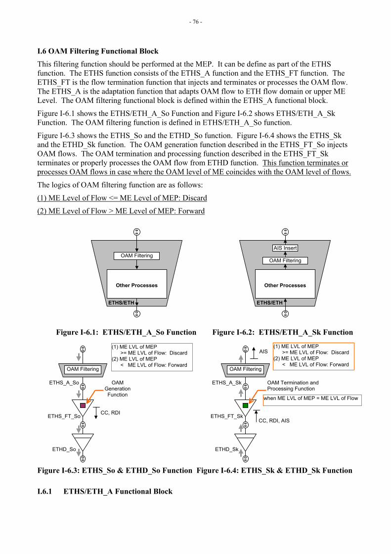
- 76 -
I.6 OAM Filtering Functional Block This filtering function should be performed at the MEP. It can be define as part of the ETHS function. The ETHS function consists of the ETHS_A function and the ETHS_FT function. The ETHS_FT is the flow termination function that injects and terminates or processes the OAM flow. The ETHS_A is the adaptation function that adapts OAM flow to ETH flow domain or upper ME Level. The OAM filtering functional block is defined within the ETHS_A functional block.
Figure I-6.1 shows the ETHS/ETH_A_So Function and Figure I-6.2 shows ETHS/ETH_A_Sk Function. The OAM filtering function is defined in ETHS/ETH_A_So function.
Figure I-6.3 shows the ETHS_So and the ETHD_So function. Figure I-6.4 shows the ETHS_Sk and the ETHD_Sk function. The OAM generation function described in the ETHS_FT_So injects OAM flows. The OAM termination and processing function described in the ETHS_FT_Sk terminates or properly processes the OAM flow from ETHD function. This function terminates or processes OAM flows in case where the OAM level of ME coincides with the OAM level of flows.
The logics of OAM filtering function are as follows:
(1) ME Level of Flow <= ME Level of MEP: Discard
(2) ME Level of Flow > ME Level of MEP: Forward
Figure I-6.1: ETHS/ETH_A_So Function Figure I-6.2: ETHS/ETH_A_Sk Function
Figure I-6.3: ETHS_So & ETHD_So Function Figure I-6.4: ETHS_Sk & ETHD_Sk Function
I.6.1 ETHS/ETH_A Functional Block
OAM Filtering
ETHS_A_So
ETHS_FT_So
ETHD_So
CC, RDI
OAM Generation
Function
OAM Filtering
ETHS_A_Sk
ETHS_FT_Sk
ETHD_Sk
CC, RDI, AIS
OAM Termination and Processing Function
AIS
when ME LVL of MEP = ME LVL of Flow
(1) ME LVL of MEP >= ME LVL of Flow: Discard (2) ME LVL of MEP < ME LVL of Flow: Forward
(1) ME LVL of MEP >= ME LVL of Flow: Discard (2) ME LVL of MEP < ME LVL of Flow: Forward
ETHS/ETH ETHS/ETH
OAM Filtering
Other Processes
AIS Insert
OAM Filtering
Other Processes
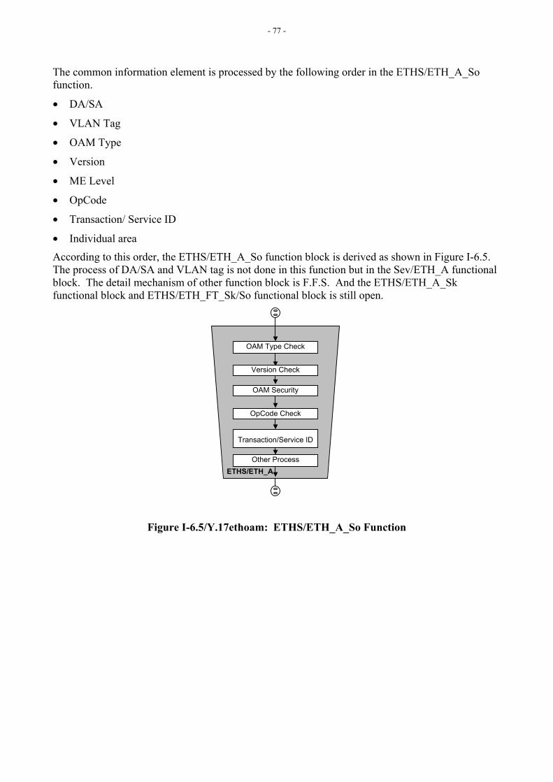
- 77 -
The common information element is processed by the following order in the ETHS/ETH_A_So function.
• DA/SA
• VLAN Tag
• OAM Type
• Version
• ME Level
• OpCode
• Transaction/ Service ID
• Individual area
According to this order, the ETHS/ETH_A_So function block is derived as shown in Figure I-6.5. The process of DA/SA and VLAN tag is not done in this function but in the Sev/ETH_A functional block. The detail mechanism of other function block is F.F.S. And the ETHS/ETH_A_Sk functional block and ETHS/ETH_FT_Sk/So functional block is still open.
Figure I-6.5/Y.17ethoam: ETHS/ETH_A_So Function
ETHS/ETH_A
OAM Security
OAM Type Check
Version Check
OpCode Check
Other Process
Transaction/Service ID

- 78 -
Appendix J: Performance Reference Models/Examples
[Editors’s Note May2005] This appendix will address Item 7 of WD06r3.
- 79 -
Appendix K: Open Discussion Items
K.1 ETH-CC Discussions This is related to Section 7.1
• Need for Lifetime is being determined. This is being done via a liaison to Q.14/15, TMF, and SG4. Liaison questions:
o do we need a mechanism to detect mismatch between the ETH-CC transmission rate between a pair of MEPs,
o do we expect to allow temporarily different ETH-CC transmission rates between MEPs in the same MEG in the same application,
o do we expect the operators to change the ETH-CC transmission rates once that have configured the MEPs with one value.
• Specific information needed to be maintained in a MEP DB being maintained at a MEP is being discussed.
K.2 Unicast ETH-LB Discussions This is related to Section 7.2.1
• It is currently assumed that while processing a Unicast ETH-LB request frame, the receiving MIP or MEP does not validate it for dMismerge (mis-merge) condition i.e. does not check the MEG ID. The implication is that if some validation is needed to check for MEG ID, the diagnostic function of MIP would require extra processing. Question to Q.14/15, Q.9/15 – Are there any potential security issues/concerns?
K.3 Multicast ETH-LB Discussions This is related to Section 7.2.2
• It is indicated that since a single request can result in many responses, the use of Multicast ETH-LB should be limited to out-of-service diagnostics. Q.9/15 – Is there a way to associate the support of this function based on a MEP state which is associated with e.g. administrative diagnostics etc?
K.4 Multicast ETH-LB Discussions
This is related to Section 7.3
• It has been assumed that a MIP is identified using its MAC address. Question.14/15, TMF, SG4 – Is a MAC address acceptable as an identifier for a MIP or a logical identifier desirable for a MIP? I.e. Is a MIP ID (different from MIP’s MAC address) needed for management purposes?
K.5 MEP/MIP and Port Status and Relationship Discussions This is related to Section 6.2
We need to identify the specific relationships between the operational and administrative states (including diagnostic states). This may also result in the need for a new OAM signal i.e. LCK (e.g. as defined in G.709). This is for FFS. Contributions are invited.