draft future communication study- technology pre … · draft future communication study-...
TRANSCRIPT
EUROPEAN ORGANISATION FOR THE SAFETY OF AIR NAVIGATION
EUROCONTROL
EUROPEAN AIR TRAFFIC CONTROL HARMONISATION AND INTEGRATION PROGRAMME
DRAFT
Future Communication Study-
Technology Pre-Screening
FCS-TECH.ASSMT
Edition : 0.9 Edition Date : 17th December 2004 Status : Working Draft Class : General Public
DOCUMENT IDENTIFICATION SHEET
DOCUMENT DESCRIPTION
Document Title
Future Communication Study - Technology Pre-Screening
EWP DELIVERABLE REFERENCE NUMBER
PROGRAMME REFERENCE INDEX EDITION : 0.9
EDITION DATE : 17/12/2004
Abstract The VHF aeronautical spectral capacity is under increasing pressure as air traffic increases and it is anticipated that saturation will be reached and a new, alternative technology will be required by 2015. In this draft report technology options for future ground/air communication are described and an initial assessment made according to criteria for voice and data services in various airspace classes. Based on the score from this assessment technology has been ranked. Further work is required to confirm the acceptability of the assessment criteria and match them with the emerging requirements from the Communications Operating Concept and Requirements work.
Keywords COMMUNICATIONS CNS/ATM
CONTACT PERSON : Philippe Renaud TEL : 3373 DIVISION : DASCSM
DOCUMENT STATUS AND TYPE
STATUS CATEGORY CLASSIFICATION Working Draft Executive Task General Public Draft Specialist Task EATCHIP Proposed Issue Lower Layer Task Restricted Released Issue
ELECTRONIC BACKUP
INTERNAL REFERENCE NAME : HOST SYSTEM MEDIA SOFTWARE(S)
Microsoft Windows Type : Hard disk Media Identification :
Edition : Working Draft Page iii
DOCUMENT APPROVAL
The following table identifies all management authorities who have successively approved the present issue of this document.
AUTHORITY NAME AND SIGNATURE DATE
Head CSM Mel Rees Dec 2004
Head Comms Domain
Jacky Pouzet Dec 2004
Project Officer Philippe Renaud Dec 2004

Edition : Working Draft Page iv
DOCUMENT CHANGE RECORD
The following table records the complete history of the successive editions of the present document.
EDITION DATE REASON FOR CHANGE SECTIONS
PAGES AFFECTED
0.9 17/12/04 Original All
Edition : Working Draft Page v
TABLE OF CONTENTS
DOCUMENT IDENTIFICATION SHEET........................................................................................... ii
DOCUMENT APPROVAL................................................................................................................ iii
DOCUMENT CHANGE RECORD ................................................................................................... iv
TABLE OF CONTENTS.................................................................................................................... v
FOREWORD.................................................................................................................................... vi
1. INTRODUCTION..................................................................................................... 1-1 1.1 Contractual Details ............................................................................................... 1-1 1.2 Background ........................................................................................................... 1-1 1.3 Scope ..................................................................................................................... 1-2 1.4 Report Structure.................................................................................................... 1-2
2. EVALUATION CRITERIA....................................................................................... 2-3
3. CANDIDATE TECHNOLOGIES ............................................................................. 3-4 3.1 Introduction ........................................................................................................... 3-4 3.2 Second Generation Cellular Mobile (2G) ............................................................ 3-4 3.3 Development of 2G Systems (2.5G) .................................................................... 3-6 3.4 Third Generation Cellular Mobile (3G) ................................................................ 3-8 3.5 Public Safety Radio Technologies .................................................................... 3-16 3.6 Wireless LAN Technologies............................................................................... 3-25 3.7 802.11 ................................................................................................................... 3-25 3.8 HiperLAN.............................................................................................................. 3-28 3.9 802.15 ................................................................................................................... 3-28 3.10 802.16 ................................................................................................................... 3-28 3.11 802.20 ................................................................................................................... 3-31 3.12 Range and Mobility Issues ................................................................................. 3-32 3.13 Satellite Communications .................................................................................. 3-33 3.14 Iridium .................................................................................................................. 3-33 3.15 Iridium Netted Radios ......................................................................................... 3-34
Edition : Working Draft Page vi
3.16 SDLS..................................................................................................................... 3-35 3.17 Boeing Connexion .............................................................................................. 3-36 3.18 Aero-BGAN (Swift BroadBand).......................................................................... 3-36 3.19 Military Systems.................................................................................................. 3-37 3.20 Aeronautical Systems......................................................................................... 3-38 3.21 VDL Mode 2.......................................................................................................... 3-38 3.22 VDL Mode 3.......................................................................................................... 3-38 3.23 VDL Mode 4.......................................................................................................... 3-39 3.24 B-VHF ................................................................................................................... 3-40 3.25 ADL....................................................................................................................... 3-41
4. TECHNOLOGY EVALUATIONS .......................................................................... 4-42 4.1 3G Cellular Technologies Evaluation................................................................ 4-42 4.2 Criteria 10 Spectrum protection ........................................................................ 4-47 4.3 Public Safety Radio Technologies Evaluation ................................................. 4-48 4.4 802.11 Family Technology Evaluation .............................................................. 4-52 4.5 Iridium Netted Radios Technology Evaluation................................................. 4-56 4.6 SDLS Technology Evaluation ............................................................................ 4-58 4.7 Boeing Connexion Technology Evaluation ...................................................... 4-60 4.8 Aero-BGAN/Swift Broadband Technology Evaluation .................................... 4-62 4.9 VDL Mode 2 Technology Evaluation ................................................................. 4-64 4.10 VDL Mode 3 Evaluation ...................................................................................... 4-66 4.11 VDL Mode 4 Evaluation ...................................................................................... 4-68 4.12 B-VHF Evaluation ................................................................................................ 4-70 4.13 ADL Evaluation.................................................................................................... 4-73
5. EVALUATION COMPARISON ............................................................................. 5-76 5.1 Approach ............................................................................................................. 5-76 5.2 Coverage.............................................................................................................. 5-76 5.3 Frequency Bands ................................................................................................ 5-76 5.4 Meeting Voice Criteria ........................................................................................ 5-77 5.5 Meeting Basic Data Criteria................................................................................ 5-80 5.6 Meeting Extended Data Criteria ......................................................................... 5-82 5.7 Overall Combined Results ................................................................................. 5-82

Edition : Working Draft Page vii
6. CONCLUSIONS.................................................................................................... 6-86 6.1 Sensitivity to Criteria .......................................................................................... 6-88 6.2 Spectrum Considerations .................................................................................. 6-89
7. RECOMMENDATIONS......................................................................................... 7-92
8. REFERENCES / BIBLIOGRAPHY ....................................................................... 8-93
9. ABBREVIATIONS ................................................................................................ 9-96
10. Appendix A ITT and QinetiQ Evaluation Criteria.......................................... 10-100 10.1 Top Level Assessment of Alternative Candidates – Summary Evaluation10-100 10.2 Data Dictionary for Candidate Evaluation Criteria....................................... 10-102
11. ANNEX B Technology Evaluation Sheets..................................................... 11-112 11.1 VDL Mode 2 Evaluation Matrix....................................................................... 11-113 11.2 VDL Mode 3 Evaluation Matrix....................................................................... 11-114 11.3 XDL Mode 3 Evaluation Matrix....................................................................... 11-115 11.4 VDL Mode 4 Evaluation Matrix....................................................................... 11-116 11.5 B-VHF Evaluation Matrix ................................................................................ 11-117 11.6 ADL Evaluation Matrix .................................................................................... 11-118 11.7 APCO P-25 Evaluation Matrix ........................................................................ 11-119 11.8 TETRA Evaluation Matrix ............................................................................... 11-120 11.9 GSM/GPRS/EDGE Evaluation Matrix............................................................. 11-121 11.10 Cdma2000 1X-EV Evaluation Matrix .............................................................. 11-122 11.11 UTRA FDD Evaluation Matrix ......................................................................... 11-123 11.12 TD-SCDMA Evaluation Matrix ........................................................................ 11-124 11.13 SDLS Evaluation Matrix.................................................................................. 11-125 11.14 Aero-BGAN Evaluation Matrix ....................................................................... 11-126 11.15 Iridium Evaluation Matrix ............................................................................... 11-127 11.16 Connexion by Boeing Evaluation Matrix ...................................................... 11-128 11.17 802.11g Evaluation Matrix .............................................................................. 11-129 11.18 802.16e Evaluation Matrix .............................................................................. 11-130 11.19 802.20 Evaluation Matrix ................................................................................ 11-131 11.20 DSB-AM (25kHz) Comparison Matrix ............................................................ 11-132

Edition : Working Draft Page viii
11.21 DSB-AM (8.33kHz) Comparison Matrix ......................................................... 11-133
12. Annex C Technology Descriptions – ICAO Proformas................................ 12-134 12.1 VDL Mode 2...................................................................................................... 12-134 12.2 VDL Mode 3...................................................................................................... 12-137 12.3 VDL Mode 4...................................................................................................... 12-140 12.4 B-VHF ............................................................................................................... 12-143 12.5 ADL................................................................................................................... 12-146 12.6 APCO Project 25.............................................................................................. 12-149 12.7 TETRA .............................................................................................................. 12-152 12.8 Tetrapol ............................................................................................................ 12-155 12.9 GSM/GPRS/EDGE............................................................................................ 12-158 12.10 Cdma2000 ........................................................................................................ 12-161 12.11 UTRA-FDD........................................................................................................ 12-164 12.12 TD-SCDMA....................................................................................................... 12-167 12.13 DECT ................................................................................................................ 12-170 12.14 SDLS................................................................................................................. 12-173 12.15 Aero-BGAN/SwiftBroadband.......................................................................... 12-175 12.16 Iridium .............................................................................................................. 12-178 12.17 802.11 WLAN ................................................................................................... 12-180 12.18 802.16e WLAN ................................................................................................. 12-183 12.19 802.20 WLAN ................................................................................................... 12-186 12.20 DSB AM Voice ................................................................................................. 12-189

Edition : Working Draft Page ix
FOREWORD
Edition : Working Draft Page 1-1
1. INTRODUCTION
1.1 Contractual Details
This report was produced under the Eurocontrol Future Air to Ground Communications Technology Investigation, TRS035/04. It describes technology pre-screening carried out under TRS035/04 Work Package 2 and constitutes a deliverable document under that contract.
1.2 Background
Aeronautical air-ground voice and data communications in the VHF band will continue to experience crowding and ultimately saturation as air traffic grows and airspace is subdivided into smaller areas each requiring dedicated VHF radio frequencies. The problem is most severe in areas which the congestion is the greatest and the airspace configuration is most complex – i.e., Europe and the United States. For years, the solution to this problem has been to further divide the VHF channels into smaller bandwidths capitalizing on advancing technology in both airborne and ground radios. Currently, 25kHz channel spacing is being used in the US and 8.33kHz spacing is being used in Europe to provide the needed capacity; however, the strategy of subdividing the band into smaller and smaller segments does not appear to offer a solution to future Air Traffic Management (ATM) needs.
Dealing with this problem on a global basis has proven to be a daunting task. Various proposals exist offered by different Nations regarding the architecture of a future aeronautical air-ground radio system but none of these proposals have yet achieved wide endorsement as the path to the future. A global solution must deal with satisfying requirements for current as well as emerging operational concepts, spectrum availability and utilization, transition strategies, economics, and nationalist needs.
In the final case, the International Civil Aviation Organization (ICAO) will be faced with sorting out the various proposals for the design of the future ATM air-ground radio system. ICAO has activities underway to achieve this including the Aeronautical Communication Panel (ACP) which is addressing this requirement. However, in parallel with this effort, the United Stated Federal Aviation Administration and Eurocontrol have agreed to begin a bi-lateral study of the future system design. The ultimate objective is to define and design a global system which provides for world-wide interoperability among all Air Traffic Management (ATM) systems users (civilian, military, commercial, and individual, service providers, and users).
The future system will be one in which both data and voice operations abound. It must support new operational concepts that are being investigated and researched throughout the world as well as the emerging requirements for both voice and data communications of all types. Both new technologies as

Edition : Working Draft Page 1-2
well as system strategies must be identified to support the future air-ground radio needs. This may include concepts for use of new communication technologies as well as multi-function equipments that can be tailored to operate in differing operational environments. Indeed, although the goal is to develop global standard, it might happen that availability of different systems with their own performance, cost, spectrum, transition, characteristics would be necessary to provide the required services in different types of airspace (e.g. continental, oceanic) and therefore a single universal solution may be unachievable. In that eventuality, consideration must be given to use of multifunction or multiband radios that can work interoperably around the world.
1.3 Scope
The pre-screening assessment is based upon criteria developed as a consensus between QinetiQ, ITT and FAA. It is not concerned with the fine detail, but instead presents a broad-brush assessment based on high level criteria covering the services and capabilities from a functional, capacity and performance point of view.
The pre-screening phase considers mobile communications technologies capable or potentially capable of furnishing both voice and data services likely to meet aeronautical requirements.
Technologies within and outside the current VHF aeronautical band are considered. Out of band technologies have either a reasonable chance of obtaining a protected spectrum allocation or be modifiable to operate within such a band.
1.4 Report Structure
Section two introduces the evaluation criteria used for the technology pre-screening and the process used to apply them. Section three lists the technologies and technology groups chosen for evaluation. This is followed in section four with an initial assessment of the technologies against the criteria and weightings. Section five compares the results and presents a ranking of technologies according to suitability for the task. Conclusions are given in section six and recommendations in section seven.
The main sections are supported by a number of annexes. Annex A (Section 10) describes the evaluation criteria in detail. Annex B presents the red/yellow/green status of each of the technology evaluations against the criteria. Annex C consists of ICAO populated technology sheets for each of the evaluated technologies.

Edition : Working Draft Page 2-3
2. EVALUATION CRITERIA
The evaluation criteria applied in the technology pre-screening are a consensus view determined by an iterative process between QinetiQ, ITT and FAA.
There are four categories of criteria, as illustrated in Table 2-1.
Category Evaluation Category Description Criteria
Meets Voice Needs
Meets Basic Datalink NeedsComms Capabilities
Communication capabilities needed to support current and emerging ICAO ATM concepts Meets Expanded Datalink
Needs Technology Readiness Level
Standardization Maturity for Aeronautical Environment
Technical maturity as well as the recognition for the safety assurance required for aeronautical standardization and certification Certification
A/G Communications Infrastructure Cost
Cost of infrastructure used by the service provider as well as the cost of avionics equipage by aircraft Avionics
Spectrum Protection
Security Other
Availability of suitable AM(R)S spectrum, support for security, and practical accommodation of transition Transition
Table 2-1 Categories of evaluation criteria
The communication capabilities category divides in to three sub categories covering voice needs, basic data needs and extended data needs. The inclusion of two categories of data link needs reflects a cautious approach in which it is recognised that the extent of data exchange requirements of a future communication system has not yet been determined. It is assumed that requirements work being carried out concurrently with the pre-screening assessment, leading to publication of an Initial Communication Operating Concept and Requirements (ICOCR) document will clarify the precise requirements.
The criteria are fully described at Annex A.

Edition : Working Draft Page 3-4
3. CANDIDATE TECHNOLOGIES
3.1 Introduction
Initial considerations resulted in a shortlist of approximately fifty candidate technologies for consideration for pre-screening. Technologies fall naturally into a number of groups, each of which is considered in turn in this section.
Not every technology in each class is evaluated. Where possible similar technologies are identified and those considered to be best suited to aeronautical use are selected. The rationale used is described in each case.
3.2 Second Generation Cellular Mobile (2G)
3.2.1 GSM
Prompted by the lack of a common analogue mobile telephone system across European countries, the Conference of European Posts and Telegraphs (CEPT) in 1982 formed a study group called the Groupe Spécial Mobile (GSM) to study and develop a European public mobile telephone system. The project was later transferred to the European Telecommunication Standards Institute (ETSI), with the first GSM specifications published in 1990. It has since become a leading standard with networks established in most countries and an estimated one billion users as of early 2004 [1].
GSM is a digital system based on Time- and Frequency-Division Multiple Access (TDMA/FDMA). GSM operates with paired frequency allocations, one band being used for uplink from the Mobile Terminal (MT) to the Base Station (BS) and another for the BS to MT downlink. There are several ITU allocated frequency sets for GSM:
• GSM 400 system (Russia, Eastern Europe)
o 450.4 – 457.6 or 478.8 – 486MHz uplink
o 460.4 – 467.6 or 488.8 – 496MHz downlink
• GSM 850 system (USA and Canada)
o 824 - 849MHz uplink
o 869 - 894MHz downlink
• GSM 900 system (Europe, Asia, Australasia)
o 880 - 915MHz uplink
Edition : Working Draft Page 3-5
o 935 - 960MHz downlink
• GSM 1800 (Europe, Asia, Australasia)
o 1710 - 1785MHz uplink
o 1805 - 1880MHz downlink
• GSM 1900 (USA and Canada)
o 1850 - 1910MHz uplink
o 1930 - 1990MHz downlink
Each allocated segment is divided into carriers spaced at 200kHz (e.g. 124 carriers per 25MHz segment for GSM 900). These are then allocated between the base stations. Multiple carrier allocations can be made to a single BS. Each carrier is shared on a TDMA basis, the fundamental time slot being 0.577ms in duration. This is known as a burst period and forms the basis of a physical channel. Eight burst periods are grouped together to form a TDMA frame, within which logical channels are defined in terms of the number and position of their constituent burst periods.
A group of 26 TDMA frames forms a Traffic Channel (TCH), of which 24 are available for user traffic the rest being used for signalling and control purposes.
The resulting channel capacity of GSM is 13kbps, which after convolutional coding, block interleaving and encryption is transmitted using Gaussian Minimum Shift Keying (GMSK) at a rate of 270.833kbps. Each burst includes a training sequence for equalisation, improving performance in multipath conditions. A slow frequency hopping system may be optionally implemented in order to further improve multipath performance.
MTs pass received signal strength to the BS, which coordinates power control within the cell. This minimises co-channel interference and conserves the battery power of the MTs by ensuring that the minimum RF power levels necessary to maintain the network are used.
The primary use of GSM is voice telephony. However, data services are also available, typically at 9600bps.
GSM cells are limited to approximately 35km diameter.
3.2.2 IS-136
IS-136 D-AMPS is a TDMA-based system developed by AT&T Wireless, now being superseded in most places by GSM. IS-136 has enjoyed significant popularity in the USA.
Edition : Working Draft Page 3-6
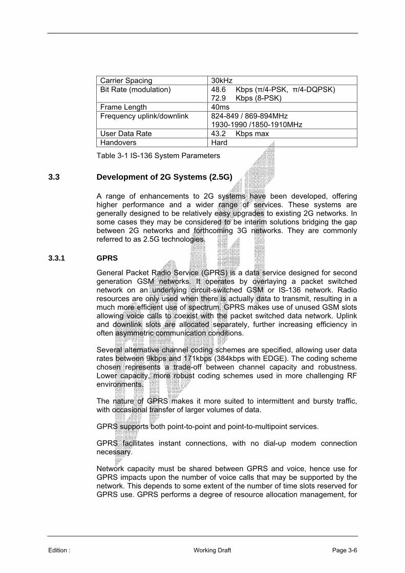
Carrier Spacing 30kHz Bit Rate (modulation) 48.6 Kbps (π/4-PSK, π/4-DQPSK)
72.9 Kbps (8-PSK) Frame Length 40ms Frequency uplink/downlink 824-849 / 869-894MHz
1930-1990 /1850-1910MHz User Data Rate 43.2 Kbps max Handovers Hard
Table 3-1 IS-136 System Parameters
3.3 Development of 2G Systems (2.5G)
A range of enhancements to 2G systems have been developed, offering higher performance and a wider range of services. These systems are generally designed to be relatively easy upgrades to existing 2G networks. In some cases they may be considered to be interim solutions bridging the gap between 2G networks and forthcoming 3G networks. They are commonly referred to as 2.5G technologies.
3.3.1 GPRS
General Packet Radio Service (GPRS) is a data service designed for second generation GSM networks. It operates by overlaying a packet switched network on an underlying circuit-switched GSM or IS-136 network. Radio resources are only used when there is actually data to transmit, resulting in a much more efficient use of spectrum. GPRS makes use of unused GSM slots allowing voice calls to coexist with the packet switched data network. Uplink and downlink slots are allocated separately, further increasing efficiency in often asymmetric communication conditions.
Several alternative channel coding schemes are specified, allowing user data rates between 9kbps and 171kbps (384kbps with EDGE). The coding scheme chosen represents a trade-off between channel capacity and robustness. Lower capacity, more robust coding schemes used in more challenging RF environments.
The nature of GPRS makes it more suited to intermittent and bursty traffic, with occasional transfer of larger volumes of data.
GPRS supports both point-to-point and point-to-multipoint services.
GPRS facilitates instant connections, with no dial-up modem connection necessary.
Network capacity must be shared between GPRS and voice, hence use for GPRS impacts upon the number of voice calls that may be supported by the network. This depends to some extent of the number of time slots reserved for GPRS use. GPRS performs a degree of resource allocation management, for

Edition : Working Draft Page 3-7
example making use of SMS messaging on the GSM network for short messages, in order to minimise its impact on the host network.
The full data rate is only achieved when all timeslots are allocated to a single user. In practice users will have to share this capacity.
QoS guarantees of packet switched systems are generally looser than those of equivalent circuit-switched systems e.g. latency tends to be higher.
Data rate 115.2 –182.4kbps (depends on coding) Handover Hard Modulation GMSK Carrier spacing 200kHz Carrier bit rate 270.833kbps Frame length 4.615ms
Table 3-2 GPRS System Parameters
3.3.2 EDGE
The Enhanced Data rates for GSM Evolution (EDGE) system is designed to offer data rates similar to those of 3G systems for the global transition of GSM and IS-136 to 3G. It is possible to upgrade both GSM and IS-136 systems to EDGE. It is also known as UWC-136.
EDGE is closely related to GSM but uses an 8 Phase Shift Keying (8-PSK) modulation scheme in contrast to GSM’s Gaussian Minimum Shift Keying (GMSK) scheme. This higher order modulation allows 48kbps per GSM timeslot. The overall result of this is a theoretical maximum user data rate of 384kbps.
The trade-off for this increased performance is reduced susceptibility to noise and interference. A higher signal quality is required in order to achieve the highest EDGE data rates. In practice this means that smaller cells are required and therefore more base stations. In standard sized cells EDGE can typically achieve 150kbps.
3.3.3 IS-95 cdmaOne
cdmaOne (also known as IS-95) was developed by Qualcomm and introduced as the first commercial CDMA service in 1995. The original IS-95A specification supports voice, 14.4kbps circuit switched and packet switched data. An enhanced IS-95B specification extends packet switched data capability up to 115.2kbps.
cdmaOne is the dominant 2G technology in North America, Korea and Japan. It has the advantage of a clear upgrade path to cdma2000.
cdmaOne operates in the bands:
• 824-849MHz UL 869-894MHz DL (US Cellular)

Edition : Working Draft Page 3-8
• 1850-1910 UL 1930-1990 DL (US PCS)
The downlink signal incorporates a pilot channel which handles tasks such as RF power control. Other channels are assigned to various services e.g. speech, data and messaging. Data or digitised speech has forward error correction coding added, with a resultant data rate of 19.2kbps. This is then spread via a 64 bit Walsh code and transmitted at a chipping rate of 1.228Mcps using QPSK or offset-QPSK.
Uplink signals have stronger FEC coding applied, resulting in a 28.8kbps data rate. A two stage spreading process is then applied, using a Walsh code and a short PN code, again resulting in a transmitted chipping rate of 1.228Mcps. This process allows for faster synchronisation of the BS receiver with the MT Walsh code, necessary because of the distributed and mobile nature of the MTs. In contrast, base stations may remain in synchronisation with each other, easing the process of synchronising the MT receiver with the BS codes.
Since adjacent cells may use the same frequencies it is possible to arrange for very reliable handover between cells, provided the MT is equipped to decode two signals at the same time. As the MT approaches the boundary between cells, both cells may transmit the signal it aims to receive. Once the level of the destination cell’s signal breaches a certain threshold the MT may transfer entirely over to the new cell, with no interruption in reception. This is known as a Soft Handover.
Multiple access CDMA Modulation QPSK/0-QPSK Carrier spacing 1.25MHz Carrier bit rate 1.2288Mcps Frame length 20ms Slots per frame 1 Frequency band (uplink/downlink) [MHz]
824-849/869-894 1930-1990 /1850-1910
Maximum possible data rate
IS95A : 14.4kbps IS95B : 115.2kbps
Handover Soft
Table 3-3 cdmaOne System Parameters
3.4 Third Generation Cellular Mobile (3G)
In recent years there has been huge commercial investment in technologies aimed at the global mobile telephone market with the goal of achieving low cost, high bandwidth communications with mobile terminals. Unlike the previous highly successful 2G networks which were designed primarily to carry voice services the 3G technologies are geared towards multimedia services at much higher data rates.
Edition : Working Draft Page 3-9
3G systems are characterised by the use of Code Division Multiple Access (CDMA) techniques in contrast to the TDMA and FDMA techniques prevalent in earlier generations. MTs can move at higher velocities (typically 300kph – 500kph) than in 2G networks and roaming capabilities extend globally.
Like the 2G and 2.5G technologies they have a cellular structure relying on a network of base stations (BS) connected with wired and wireless links. MTs within a cell communicate with the local BS with calls routed either to another MT within the same cell or via the backhaul network to MTs or fixed terminals in other cells or on other networks.
Messages are exchanged between MTs and BSs on a regular basis whether or not a call is in progress. This allows the network to maintain awareness of which cell a given MT is currently in. Cells are grouped in to Local Areas (LA) and LAs are grouped in to Gateway Local Areas (G-LAs). In 3G systems a two or three-tier system of databases is used to keep track of MTs. The Home Location Register (HLR) is updated with an MT’s location when it moves across a G-LA boundary. The optional Gateway Location Register (GLR) is updated when an MT moves across an LA boundary. The Visitor Location Register (VLR) is updated when the number of times an MT moves between cells exceeds a certain threshold. Maintenance of these databases results in a high probability of polling the correct cell first time when setting up an incoming call.
Various handoff methods may be implemented where an MT with a call in progress moves between cells.
3G systems implement power control algorithms in order to minimise interference between transmitters within the cell and between adjacent cells. This is a key technique enabling the use of CDMA methods.
There are two primary 3G systems:
• UMTS
• cdma2000
3.4.1 UMTS
The Universal Mobile Telecommunications System (UMTS) standard is specified by the 3rd Generation Partnership Project (3GPP), a joint project of the standardisation bodies of Europe, Japan, Korea, the USA and China. It can be considered to be a development of GSM technology via GPRS and EDGE.
UMTS has two main versions based on Frequency Division Duplex (FDD) and Time Division Duplex (TDD). These are typically referred to as UMTS Terrestrial Radio Access (UTRA) FDD and UTRA TDD. UTRA FDD and UTRA TDD are both Wideband Code Division Multiple Access (W-CDMA) systems. UTRA TDD, developed by Siemens, is based on Time Division-Code Division Multiple Access (TD-CDMA). An alternative but closely related

Edition : Working Draft Page 3-10
system, Time Division-Synchronous Code Division Multiple Access (TD-SCDMA), was developed by the China Academy of Telecommunications Technology (CATT) in collaboration with Siemens. It is used almost exclusively in China.
TD-SCDMA uses TDD, with time slots allocated to uplink or downlink according to the level of traffic in each direction. The system is designed to operate at up to 250 kph, though in common with other 3G systems data rate degradation is likely to be experienced at higher velocities. Smart antennas are used with TD-SCDMA to minimize interference. The system is being promoted by China Mobile and China Unicom through a TD-SCDMA forum
Basic UMTS parameters are given in Table 3-4.
System UTRA-FDD UTRA-TDD TD-SCDMA Frequency band
1920-1980MHz 2110-2170MHz
1900-1920MHz 2010-2025MHz
2010-2025MHz
Minimum frequency band required
2x5MHz 5MHz (1.6MHz with 1.28 Mcps)
1.6MHz
Frequency re-use Factor
1 1 1 (or 3)
Carrier Spacing
4.4MHz - 5.2 MHz (with 200kHz channel raster)
5MHz Unpaired (with 200kHz channel raster)
-
Maximum number of (voice) channels on 2x5MHz
~196 (spreading factor 256 UL, AMR 7.95kbps) ~98 (spreading factor 128 UL, AMR 12.2kbps)
- -
Voice coding AMR 4.75-12.2 kHz GSM EFR 12.2 kHz
AMR GSM EFR
-
Channel coding
Convolutional coding, Turbo code for high rate data
Convolutional coding, Turbo code for high rate data
-
Receiver sensitivity
BS: -121dBm MT: -117dBm (BER 10-3)
- -
Data services Packet switched Circuit switched
Packet switched Circuit switched
-
Modulation QPSK QPSK QPSK or 8-PSK

Edition : Working Draft Page 3-11
System UTRA-FDD UTRA-TDD TD-SCDMA Pulse shaping
Root raised cosine (0.22)
Root raised cosine (0.22)
-
Chip rate
3.84 Mcps 3.84 Mcps or 1.28 Mcps
1.28 Mcps
Maximum user data rate (Physical channel)
~ 2.3Mbps typical. Max user data rate 384kbps. Up to 2Mbps possible. HSPDA to 10Mbps MIMO to 20Mbps
~ 3.3Mbps Voice data rate: 8kbps Circuit switched services: 12.2 kbps, 64kbps, 144kbps, 384kbps, 2048kbps Packet data: 9.6kbps, 64kbps, 144kbps, 384kbps, 2048kbps
Channel bit rate
5.76Mbps - -
Frame length 10ms
10ms
10ms 5ms?
Slots / frame 15 15 7
Multirate method
Multicode Multislot OVSF
Multicode OVSF
-
Handovers
Soft Softer Hard
Hard
Hard Baton handover Uplink synch
Power control period
1500 Hz (closed loop)
100 Hz or 200 Hz Uplink (open loop) 800 Hz Downlink (closed loop)
200 Hz
Power control step size
0.5, 1, 1.5, 2dB 1, 2, 3dB -
Power control range
Uplink 80dB Downlink 30dB
Uplink 65dB Downlink 30dB
-
Mobile peak power
class 1 +33dBm class 2 +27dBm, class 3 +24dBm, class 4 +21dBm
class 1 +33dBm class 2 +27dBm, class 3 +24dBm, class 4 +21dBm
-
Number of unique BS ID codes
512/frequency
512/frequency -
Physical layer spreading factors
4-256 Uplink 4-512 Downlink
1-16 1-16
Table 3-4 Comparison of 3G System Parameters

Edition : Working Draft Page 3-12
Of the two main UMTS methods, FDD is more suited to larger cell sizes. The use of propagation guard intervals within the slot structure places limits on cell size. For example a typical Burst Type III guard period is 50µs, suitable for a cell radius of 7.5km.
3.4.2 cdma2000
cdma2000 is a Third Generation Partnership Project 2 (3GPP2) standard originally developed by Qualcomm. 3GPP2 is a partnership consisting of five telecommunications standards bodies: ARIB and TTC in Japan, CWTS in China, TTA in Korea and TIA in North America. cdma2000 has the advantage of having a relatively easy upgrade path from cdmaOne and provides integrated voice with simultaneous high rate packet-switched data services.
The cdma2000 standard is based on multi-carrier CDMA and has several versions, each expanding on and improving the services offered by previous versions. These are known as:
• cdma2000 1X
• cdma2000 1X EV-DO
• cdma2000 1X EV-DV
• cdma2000 3X
Basic cdma2000 frames have 20ms duration, within which are 16 1.25ms power control intervals. This enables power control at up to 800 Hz. However, options are available for reducing the power control rate to 400 Hz or 200 Hz depending upon the mode of operation. A slower open loop power control system is also implemented to counter slow channel fades.
cdma2000 base stations are synchronised to Universal Coordinated Time (UCT), their transmission timing remaining synchronised to within a few microseconds. This facilitates faster channel acquisition and improved handovers, since the usual time synchronisation process can be simplified.
cdma2000 makes use of transmit diversity to improve system performance. This is achieved by generating two orthogonal signals with either Orthogonal Transmit Diversity (OTD) or Space-Time Spreading (STS) and transmitting them from separate antennas. The receiver can then exploit the space and frequency diversity of the signal to improve detection.
cdma2000 may optionally apply either turbo coding or convolutional coding to transmitted data. ½ rate, 1/3 rate and ¼ rate codes are supported.
cdma2000 1X offers data rates up to 144kbps on a single 1.25MHz carrier in its initial Release 0, increasing to 384kbps (for non-mobile users) with Release A. It uses the same core network as IS-95 and is designed to be able to co-

Edition : Working Draft Page 3-13
exist with IS-95 MTs, but offers double the voice capacity of IS-95. Its associated standard is IS-2000, which was published by the Telecommunications Industry Association (TIA) in 2000. It is capable of simultaneous voice and data services. It is a commercially successful system with a large number of network operators.
cdma2000 1X EV-DO refers to 1X Evolution Data Only. It is an enhancement to 1X which uses separate carriers for voice and data in order to achieve a data rate of 2.4Mbps downlink and 153kbps uplink. The user experience is of an ‘always on’ IP data service. cdma2000 is implemented on a small but growing number of commercial networks.
cdma2000 1X EV-DV (1X Evolution Data and Voice) is a further development which offers 3.09Mbps peak downlink and 451.2kbps peak uplink data rates. The system exploits several techniques to achieve this level of performance, including adaptive modulation and coding with multilevel modulation schemes (QPSK, 8-PSK and 16QAM), turbo coding, variable packet sizes and durations, and high rate power control. No commercial networks yet but trials underway.
cdma2000 3X increases the spectrum requirement to 3.75MHz uplink and 3.75MHz downlink; 2Mbps to 4Mbps). The system is still in development.
Channel Bandwidth
1x: 2x1.25MHz 3x: 2x3.75
Chip rate 1x 1.2288 3x: 3.6864 Mcps Maximum user data rate
1x:144kbps Release 0 1x:307kbps Release A 1xEV-DO: max 384kbps - 2.4 Mbps 1xEV-DV: 4.8 Mbps.
-
Frame length 5ms, 10ms or 20ms Modulation QPSK Power control rate
800 Hz
FEC Turbo or convolutional codes Spreading factors 4-256
Table 3-5 cdma2000 System Parameters
3.4.3 Standardisation Groups
The International Mobile Telecommunications 2000 (IMT-2000) is the global standard for 3G wireless communications, defined by a set of interdependent ITU Recommendations.
Standards adopted for IMT-2000 are:
• IMT-MC multicarrier (cdma2000)
• IMT-SC single carrier (UWC-136)

Edition : Working Draft Page 3-14
• IMT-DS direct sequence (UTRA FDD)
• IMT-TC TDMA/CDMA (UTRA TDD, TD-SCDMA)
• IMT-FT FDMA/TDMA (DECT)
In June 1999 a harmonisation of 3GPP and 3GPP2 concepts was proposed by the Operator Harmonisation Group (OHG). This initiative is known as Global Third Generation (G3G) and aims to achieve interoperability between UTRA and cdma2000 systems. This has been accepted by 3GPP and 3GPP2 as a concept to produce a standard with three operating modes:
• CDMA-DS (CDMA - Direct Sequence), based on UTRA FDD
• CDMA-MC (CDMA - Multi Carrier), based on cdma2000
• CDMA-TDD, based on UTRA TDD
3.4.4 Push to Talk
2G and 3G voice communications are characterised by the need to dial the intended recipient and wait until a connection is established. This process may take several seconds and is therefore unsuitable for use in high density airspace. In contrast, most 3G data services are of the ‘always on’ variety. This difference in service is rooted in the fundamental difference between voice and data communications on digital systems.
Most data services may be characterised by the rule ‘use the highest data rate available at the time’. Thus data services tend to be implemented with user data rates varying in accordance with RF propagation conditions, number of users in the cell and their particular data transfer demands. This allows best use of cell capacity and enables an ‘always on’ service, since network resources need not be devoted to an MT until it needs to send or receive data (i.e. a packet-switched network). Under periods of heavy loading the effect is simply to reduce the data rate at each MT. Conversely voice communications require a data rate below which speech quality is unacceptable, but above which no benefit is gained. A voice channel must therefore be guaranteed a minimum data rate, hence the need to establish a connection (essentially a circuit-switched link) before a voice call can take place.
As network capacities have increased it has become technically possible to carry voice on the packet-switched data side of the network. This and related techniques have led to the development of ‘push to talk’ services based on 2.5G and 3G networks. Typically an MT will display a ‘buddy list’ of contacts, indicating which of them is currently switched on and connected to the network. The user may then establish the equivalent of a group conference call by selecting who to include from the list. Thereafter any member of the group call may speak to the others in the group by pressing a button on the handset. This mimics the action of conventional VHF radios with a PTT facility.

Edition : Working Draft Page 3-15
Several network operators are offering a PTT service, including Verizon, Sprint, Bell Mobility, Telus Mobility and Orange “Just Talk”. In the USA PTT services such as Nextel “Direct Connect” and Motorola “iDEN” have in the past been provided via separate Specialised Mobile Radio (SMR) networks. However, these new PTT services use the existing 2G or 3G networks.
In October 2003 Ericsson, Motorola, Nokia and Siemens Mobile announced a jointly developed Push to talk over Cellular (PoC) specification based on the IP Multimedia Subsystem (IMS) as defined by 3GPP had been completed. The PoC specification is supported by other industry leaders such as AT&T Wireless Services, Cingular, Sonim Technologies, and Sony Ericsson.
Motorola Inc.’s Global Telecom Solutions Sector (GTSS) announced in March 2004 that it has made its standards-based PoC client software available for license to third party GSM/GPRS and UMTS handset manufacturers and software developers.
Not all systems provide instant access to the channel. Some services typically take four or five seconds to set up the call, then up to approximately one second for the PTT function. Qualcomm QChat service advertises call setup times of less than a second.
PoC allows a single group member to speak at a time. A user must request access before becoming the current speaker. The PoC standard allows up to 1.6 seconds delay between this request being made and subsequent granting or denial of this request. The standard also allows up to 1.6 seconds voice latency. It is clear that these delays would be unacceptable in dense airspace, though it is assumed that practical systems will perform rather better than the standard allows for by 2015.
An alternative method of achieving party line PTT functionality is to make use of conference calling technology. A teleconference would be associated with each air traffic controller. Pilots entering an area would call the associated teleconference, thereafter making use of modified hardware to implement a PTT function. It may also be possible to have such a call transferred to the teleconference associated with the next geographical area as the aircraft travels in to the jurisdiction of the next air traffic controller.
This requires that each cell has sufficient capacity for the PIAC associated with the cell volume, since a call will need to be established and maintained for every aircraft in that volume. The evaluation of 2.5G and 3G technologies assumes that cells may be structured with sufficient capacity for circuit-switched voice calls to be established and maintained throughout.
3.4.5 Application of cellular technology to Air to Ground Communication
Cellular telephone infrastructure is designed to provide services to users on or near to the ground, travelling up to vehicular speeds often in urban environments with strong multipath propagation characteristics. The air to ground communication scenario differs in several key ways.
Edition : Working Draft Page 3-16
Base station antennas are configured to provide good cell or sector coverage and minimise interference to adjacent cells. Typically antennas are placed as high up as possible on towers or roof tops, with their main lobes angled slightly downwards. Little energy is radiated upwards. Aeronautical use would require a different antenna design giving upward coverage.
This immediately changes the geometry of the scenario. Cell size in conventional networks can be chosen in a relatively unconstrained manner, allocating smaller cells to cover denser usage areas. In an aeronautical application cell radius (as defined by the power limited range of a base station with consideration to any interference from adjacent cells) also affects the maximum altitude at which an aircraft may be communicated with. Thus in order to achieve sufficient altitude the lateral extent of a cell may have to be significantly larger than a terrestrial cell, depending upon the antenna radiation pattern selected. This does not necessarily result in a capacity problem since the volumetric density of air traffic is generally much lower than that of the MTs that 3G systems are designed for.
Cell size is also an issue for those technologies with a TDMA or TDD element. Propagation guard times are built in to the waveforms, resulting in a maximum limit on functional cell size.
3.5 Public Safety Radio Technologies
Public safety radio systems are designed for use by the emergency services such as the police, fire brigade and ambulance services. Implementations differ across the globe. Table 3-6 lists the major systems according to access method and bandwidth.
Access Narrowband Wideband Broadband FDMA APCO P25 Phase I
Tetrapol EDACS
Motorola Greenhouse (SAM)
TDMA TETRA APCO P25 Phase II DIMRS IDRA
Project MESA
Table 3-6 Public Service Radio Systems
3.5.1 APCO P25
Project 25 was established in 1989 by the Associated Public Communications Officers (APCO) with the aim of specifying a common standard for US public services land mobile radio. The resulting APCO P25 Phase 1 standard is complete. It is not a single standard but instead defines a number of compatible protocols which may be combined to produce a P25 compliant system. Thus depending upon the options chosen a P25 radio may carry voice, data or both, encrypted or in the clear, on a conventional or trunked
Edition : Working Draft Page 3-17
radio architecture. Minimum compliance requires implementation of the P25 Common Air Interface (CAI) and the P25 Improved Multi-Band Excitation (IMBE) vocoder.
APCO P25 Phase 1 is an FDMA system using 12.5 kHz channels, with a 6.25kHz channel option. Backward compatibility with analogue voice is extended with the capability to transmit data at 9600bps. Other modes are available that carry a mix of voice and data.
P25 Phase 2 is not yet finalised but will see the adoption of 6.25kHz channels with a two or four slot TDMA structure in addition to compatibility with the FDMA mode. Investigations have been made in to the possibility of incorporating a modified version of TETRA as the P25 Phase 2 TDMA system.
Project 25 systems are currently operated in the VHF, UHF, and 800MHz public safety bands and have the ability to coexist with existing analogue systems. Phase I uses C4FM, a four level FM modulation interoperable with C-QPSK modulation chosen for Phase II. Both phases share the same channelisation, bit rate (9600bps), vocoder and encryption technique.
In the United States 24MHz of spectrum has been allocated for public safety in the 700MHz band, with P25 Phase I specified as the interoperability mode. The band may be used with 6.25kHz channelisation (aggregated to 25kHz for combined voice and data) and also supports 50kHz channels that may be aggregated to 100kHz or 150kHz for wideband systems (see section on SAM and IOTA).
P25 radios may be used either conventionally or in a trunked configuration, with voice and data formats common to both modes of operation. Facilities are available for voice, data and system control message encryption. Services allow voice communications in a group call, private call, or interconnect call. Data modes include both circuit-switched and packet-switched services.
P-25 services include
• Individual Voice Call
• Broadcast/Unaddressed Voice Call
• Group Voice Call
• Circuit Switched Data Network Access
• Packet-Switched Data Network Access
• Pre-programmed Data Messaging
• Pre-emptive Priority Call
• Call Interrupt

Edition : Working Draft Page 3-18
• Voice Telephone Call
• Talking Party Identification
• Call Alerting
• Intra-system Roaming
• Inter-system Roaming
• Encryption Update
Phase 3 envisaged the introduction of high speed data services, and adopted the name Project 34. The Statement of Requirements produced for P34 was recognised to have considerable overlap with a similar European project, Digital Advanced Wireless Services (DAWS). Agreements of cooperation lead to the establishment of a collaborative project between TIA and ETSI initially in the form of the Public Safety Partnership Project (PSPP) and more recently as Project MESA (Mobility for Emergency and Safety Applications) [2].
3.5.2 TETRA
Terrestrial Trunked Radio (TETRA) is the ETSI standard for digital trunked land mobile radio. It is widely deployed in Europe, Far East (notably in China), Middle East, Africa and South America.
The TETRA standards were introduced in 1995 with the first systems becoming operational in 1997.
TETRA is based on a four slot TDMA system, giving four logical channels per 25kHz physical channel with an aggregate data rate of 36kbps using π/4 DQPSK modulation.
Each logical channel can support speech using the 4.567kbps ACELP (Algebraic Code Exited Linear Prediction) codec. FEC coding brings this up to 7.2kbps. Uplink and downlink functions are separated on different frequencies.
Alternatively a channel can support user data at up to 7.2kbps. Multiple channels and levels of FEC can be combined in various ways to give data rates up to 28.8kbps to a single user or group. Data rate options are described in Table 3-7.
Slots No Protection Low Protection High Protection 1 7.2 4.8 2.4 2 14.4 9.6 4.8 3 21.6 14.4 7.2 4 28.8 19.2 9.6
Table 3-7 TETRA Data Rates [kbps]

Edition : Working Draft Page 3-19
The TETRA TDMA structure incorporates a signalling channel which utilises every 18th four-slot frame. Amongst other functions this signalling channel is used to synchronise mobile terminals and can be used to notify radios already engaged in a call of attempts by other radios to contact it.
TETRA frequency allocations are:
• 380-390/390-400MHz (380-395 MHz for cross-border cooperation)
• 410-420/420-430MHz
• 450-460/460-470MHz
• 870-888/915-933MHz (outside Europe)
The core TETRA standard offers voice and data trunked communication. Time slots may be allocated to control messages, voice, circuit switched data or packet switched data. There is also a half duplex Direct Mode (DMO) allowing direct communication between mobile terminals without the need for any external infrastructure. DMO supports gateway and relay functions to extend network coverage.
TETRA supports two levels of confidentiality. Transmissions may be encrypted at the air interface or end-to-end for a higher level of security. User authentication is also implemented.
The main voice services offered by TETRA are:
• Individual Call: A one-to-one duplex addressed voice call, very similar to a mobile telephone call from the user’s perspective. A half-duplex mode is also available;
• Group Call: A conference call initiated by a user in which all members can both hear and speak to all other members of the group on a half-duplex basis. Members may be added or removed dynamically. Group calls may only be terminated by the call owner, though call ownership may be transferred between group members. Optionally group members may be required to acknowledge acceptance of the call;
• Direct Mode: allows a group of mobile terminals to communicate without the need for a network infrastructure;
• Broadcast Call: A one-to-many simplex call to a predefined user group and/or coverage area;
• Emergency Call: A high priority pre-emptive call to an individual or group. Various priority and pre-emptive modes are implemented (11 non pre-emptive priority levels and four pre-emptive priority levels).
Edition : Working Draft Page 3-20
Person-to-person and person-to-group calls are typically set up in less than 0.5 seconds.
Data Services include:
• status messaging: very short predefined messages sent to individuals or groups;
• short data messaging: short predefined messages sent to individuals or groups;
• circuit-switched data: at various bit rates depending upon slot allocation and level of FEC;
• Packet-switched data. TCP/IP access between mobile terminals and external networks.
The TETRA maximum cell radius of 67km is dictated by the round trip delay when a mobile is at this distance from the base station, and the maximum latency of 8 symbol periods allowed for in the TETRA standard. Various methods of range extension have been considered, but involve either a reduction in capacity or significant modification of the mobile terminals and base stations.
3.5.3 Wideband systems
In the USA 24MHz of spectrum has been allocated to wideband public safety radio use at 700MHz. Typically these range in data rate between 128kbps in a 50kHz channel and 384kbps in a 150kHz wide channel. Two air interface specifications have been published by TIA. Scaleable Adaptive Modulation (SAM) has been used by the Motorola Greenhouse project. Isotropic Orthogonal Transform Algorithm is an alternative waveform developed by Nortel with a similar performance.
The Project Greenhouse system has been trialled in two locations and can achieve data rates up to 460kbps using a 150kHz band. Trials have shown the system capable of simultaneously providing live wireless mobile video, intranet/Internet access, voice other high speed packet-switched data services.
Project Greenhouse technology trials have made use of a single antenna site with a six-mile range. Emergency services personnel access the system via a vehicle-mounted colour touch-screen.
3.5.4 Project MESA
Mobility for Emergency and Safety Applications (MESA) is a collaborative project between TIA and ETSI which grew out of preliminary work to define a broadband public safety radio system. MESA intends to produce a common Statement of Requirements (SoR) for Public Safety based on very high bit-rate Applications and Services available on mobile platforms. From this MESA will

Edition : Working Draft Page 3-21
develop a set of Technical Specifications for the first phase of a Mobile Broadband System covering:
• Mobile Layer 1 (PHY) supporting bit-rates above 2Mbps;
• MESA Core Network Based on the IP v 6 and v 4 and ATM Port access;
• Mobile Link Entity (MLE) and ad hoc networking capabilities of self-healing wireless infrastructure nodes are integral parts of a MESA Core Network;
• Terminals for access to the above;
• System and service aspects.
There is currently no physical layer standard for MESA, but it is possible that MESA will take a ‘System of Systems’ approach and incorporate a number of technologies (3G, WLAN, OFDM). Technologies providing ad-hoc, rapidly deployed mobile broadband networks are likely to apply. In the USA a 50MHz band has been reserved for public safety application at 4.9 GHz. Currently a trial licence has been granted for the testing of mobile ad-hoc mesh network devices by MeshNetworks Inc. in this band. [3].
3.5.5 TETRA Release 2
TETRA release 2 aims to provide wideband data services and interoperability with 2.5G/3G public mobile networks. There are two threads to the project; TETRA Advanced Packet Service (TAPS) and TETRA Enhanced Data Service (TEDS).
TAPS is an overlay network based on GPRS/EDGE technology. It is intended to make high speed packet data services available on a short timescale and is highly dependent on GSM standards.
TEDS is aimed at providing a high speed packet data solution in a form that is integrated with the existing TETRA system. As such it is backward compatible with TETRA V+D and has operating modes that fit within the narrow spectrum available to some TETRA users.
TEDS requirements include:
• 50kbps-80kbps per user (min 50kbps at edge of coverage)
• Simultaneous voice and HSD, priority voice
• 1W max handset, 3W max vehicle
The selected technology is likely to utilise:
• Multicarrier platform with TDMA carriers
Edition : Working Draft Page 3-22
• Adaptive modulation and coding
• 4QAM/16QAM/64QAM/π/4 DQPSK/D8PSK
• Carriers: 25/50/100/150kHz
• Pilot symbol used for channel estimation
• Full & half slot sizes
• QAM carriers composed of baseband subcarriers (8 per 25kHz)
• User bit rates 30kbps – 400kbps
• TETRA V+D protocols
3.5.6 Tetrapol
The TETRAPOL standards were developed by a group of manufacturers known as the TETRAPOL Forum. TETRAPOL is an FDMA system offering digital voice and data services. It uses GMSK modulation and typically operates in bands between 70MHz to 933MHz. Carrier spacing may be selected as either 10kHz or 12.5kHz to allow compatibility with analogue systems. Duplex separation recommended is 10MHz. Tetrapol operates in the following CEPT recommended bands:
• 380-390/390-400MHz
• 410-420/420-430MHz
• 450-460/460-470MHz,
• 870-888/915-933MHz
TETRAPOL uses an RPCELP 6kbps codec with a 20ms speech frame. FEC coding is applied (Convolutional or BCH codes) together with interleaving for protection against burst errors. A single channel can support circuit-switched data at 3.2kbps with FEC and 7.6kbps without FEC.
TETRAPOL Specifications define three modes: network, direct and repeater (relay). In network mode the mobile terminal communicates via the local cell base station, either in trunking mode or open channel mode. Direct mode allows direct connection between mobile terminals without the need for infrastructure. Relay mode enables mobile terminals to communicate with each other or with the base station via a relay terminal.
Different levels of security are offered including authentication and end-to-end security.
The high receiver sensitivity enabled by use of constant envelope GMSK modulation enables large cells and fewer sites necessary to cover an area.
Edition : Working Draft Page 3-23
The possible use of simulcast over large synchronized areas enhances frequency efficiency and reduces infrastructure with very large cell coverage.
Networks can range from a single site through to local, regional and national
networks. The FDMA channel access mode allows frequencies to be reused every 12 cells because of TETRAPOL’s high immunity to co-channel interference.
Tetrapol services include:
• Individual Call: A one-to-one half-duplex addressed voice call, very similar to a mobile telephone call from the user’s perspective. Duplex is possible with more advanced hardware;
• Group Call: A conference call initiated by a user in which all members can both hear and speak to all other members of the group on a half-duplex basis. Members may be added or removed dynamically. Group calls may only be terminated by the call owner, though call ownership may be transferred between group members. Optionally group members may be required to acknowledge acceptance of the call;
• Direct Mode: allows a group of mobile terminals to communicate without the need for a network infrastructure;
• Broadcast Call: A one-to-many simplex call to a predefined user group and/or coverage area;
• Emergency Call: A high priority pre-emptive call to an individual or group. Various priority and pre-emptive modes are implemented (11 non pre-emptive priority levels and four pre-emptive priority levels);
• Paging: Unacknowledged short messages may be sent to a mobile terminal;
• Status Transmission: Very short predefined messages exchanged between mobile terminals;
• Short Data Messaging: Allows users to exchange very short messages;
• X.25 Packet Data: Circuit-switched data connection between terminals;
• TCP/IP Access: Connectionless packet data transfer.
3.5.7 EDACS
EDACS (Enhanced Digital Access Communications System) is an FDMA system with many similarities to TETRAPOL. It uses GFSK modulation with a transmission rate of 9.6kbps. It may use either 25kHz or 12.5kHz channels, with a typical uplink and downlink frequency separation of 45MHz. EDACS

Edition : Working Draft Page 3-24
provides both trunked and direct radio access modes with Individual call, group call and broadcast services.
3.5.8 DIMRS and IDRA
Digital Integrated Mobile Radio System (DIMRS) is the Canadian submission to the ITU-R for public safety radio. The Japanese Integrated Digital Radio (IDRA) submission is very similar, the two systems sharing most technical aspects. There are differences in emphasis in the type of services they provide. Both systems are based on six-slot TDMA in a 25kHz channel using 16 QAM modulation at a transmission rate of 64kbps.
DIMRS and IDRA operate in different bands:
• DIMRS 806-866MHz
• IDRA 850-915MHz and 1453-1525MHz
16 QAM requires highly linear amplifiers to ensure co-channel interference is kept down to acceptable levels. The use of four sub-channels for transmitted symbols leads to high resistance to multipath delay spreading, allowing good performance without the need for an equaliser.
Each system allows for the definition of talk groups, and for both 1:1, 1:N, and N:1 communication in the dispatch mode. Both systems also offer advanced data transmission features. These systems offer circuit data connections, connection oriented and connectionless packet data services. , paging, short message service, circuit data, and packet data services.
3.5.9 Application of public safety radio technology to Air to Ground Communication
Most public safety radio systems use a cellular approach to achieve area coverage. Radios operate in various modes, generally being capable of direct communication but often making use of a gateway to use trunk mode communications. Various relay modes are also available. Typical cell radius varies between approximately 5km and 40km depending upon the system in use, hence modification to extend cell range would be required in some cases in order to avoid the need to establish a large number of cells for aeronautical use. In some cases this might be achieved simply with higher power transmitters. However, more detailed analysis and trials would be required to establish this.
Equipment would have to be modified from standard in order to operate in aeronautical communication or navigation bands, but would otherwise be left to operate in the standard manner. This avoids the costs associated with the development of new standards. TETRA and P-25 already have equipment operating a little below the 960-1215MHz band (P-25 up to 941MHz and TETRA up to 933MHz). It is therefore likely that this would be the preferred band for their operation as aeronautical radios.

Edition : Working Draft Page 3-25
Since it requires ground infrastructure and has limited range this class of technology is applicable only in En-Route, Terminal and Surface zones. No coverage would exist in Oceanic and Polar regions, though pilot-to-pilot communication would be possible in all regions. Typical cell radius (18km for TETRA, 35km for P-25) would enable coverage to sufficient altitude for en-route operations. In practice higher transmitter powers would be likely to be employed, extending cell radius up to the maximum allowed by the respective radios’ protocols, thus easing the task of handover from cell to cell.
3.6 Wireless LAN Technologies
The IEEE has defined a large number of standards for use in Personal Area Networks (PANs), Local Area Networks (LANs) and Metropolitan Area Networks (MANs). These standards form the 802.xx categories and define a broad range of wired and wireless networking protocols.
3.7 802.11
3.7.1 Technical Overview
The 802.11 protocol has become the most widely recognized standard for commercial wireless LAN (WLAN) applications. Wireless networks based on the 802.11 standards are suitable for offices and homes, providing a range of up to 300m depending on the environment.
802.11 operates in a similar way to common fixed Ethernet LANs (802.3), using Carrier-Sense Multiple Access (CSMA). Unlike Ethernet however, 802.11 uses a Collision Avoidance (CA) protocol rather than Collision Detection (CD). In CSMA/CA, a station wishing to transmit data will first send a short frame to indicate to the network that it intends to transmit. This will be followed by the data frames if no initial collision is detected. In CSMA/CD, data is transmitted as soon as the network is seen to be available, and any collision is then resolved by conflicting stations backing off for a brief, random time delay. CSMA/CA performs better than CSMA/CD when there are medium to high levels of network traffic, as the overhead of collisions is smaller due to shorter frames colliding.
The physical layer of the 802.11 protocol can be implemented by infrared or radio, each supporting 1Mbps and 2Mbps bit rates. The radio implementation uses either frequency hopping spread spectrum (FHSS) or direct sequence spread spectrum (DSSS) techniques, and a range of different modulation methods.
Since the initial formation of the 802.11 standard there have been a number of revisions. The Table 3-8 shows details for the revisions relevant to this study. These are the most widely used standards in the 802.11 family. Other intermediate revisions were made to address issues such as network bridging, global harmonization, quality of service (QoS), roaming and security.

Edition : Working Draft Page 3-26
Standard Frequency Band
Bit Rates (Mb/s) Modulation Schemes Range
802.11 2.4GHz 1,2
2GFSK/FHSS,dBPSK/DSSS (1Mb/s)
4GFSK/FHSS, DQPSK/DSSS (2Mb/s)
<300m
802.11a 5GHz 6,9,12,18, 24,36,48,54
BPSK/OFDM (6,9Mb/s) QPSK/OFDM (12,18Mb/s)
16-QAM/OFDM (24,36Mb/s) 64-QAM/OFDM (48,54Mb/s)
100m
802.11b 2.4GHz 1,2,5.5,11 DBPSK/DSSS (1Mb/s) DQPSK/DSSS (2Mb/s)
DQPSK/DSSS/CCK (5.5,11Mb/s) 300m
802.11g 2.4GHz 1,2,5.5,6,9,
11,12,18,22,24, 33,36,48,54
Various inc. DSSS, DSSS/CCK, OFDM & PBCC 300m
Table 3-8 Details of most commonly used 802.11 versions
The original 802.11 standard has largely been made obsolete by the development of the subsequent revisions. The 802.11a protocol is less susceptible to noise and interference from other devices, such as microwave ovens, due to its higher frequency band. It also has better performance in networks with many users, though the range is more limited. The standard is not compatible with 802.11b or 802.11g.
802.11b can support a physically larger network than 802.11a with fewer access points, though 802.11g may replace this standard. 802.11g is backward compatible with 802.11b and has increased security with higher bit rate support.
3.7.2 Developing Organization
The standard was developed by a working group of the IEEE.
3.7.3 Maturity/Development Status
Development has been completed on the 802.11a/b/g standards, but work is continuing on further revisions to address issues such as security. The most widely used standard at present is 802.11b, but as 802.11g is backward compatible and is superior, it is being employed more often in new products. 802.11b and 802.11g are WiFi compatible. WiFi (Wireless Fidelity) is a standard based on 802.11b, established to promote interoperability between WLAN equipment from different manufacturers.
3.7.4 Standardization Status
The IEEE has fully standardized the 802.11 and 802.11a/b/g protocols.

Edition : Working Draft Page 3-27
3.7.5 Service Type Supported
The 802.11 protocol operates using packet data, with the number of active users determining the data throughput. Generally the system is suitable for voice, data and video transmissions as it is fairly low in the network layer model, allowing applications to operate on a higher level and use the network service provided.
3.7.6 Operating User Bandwidth and Spectrum
802.11 series standards define 11 (US) or 13 (EU) separate DSSS channels spaced 5MHz apart. DSSS channel bandwidth is 20MHz, hence operating more than three channels in the same area leads to degradation in performance. This has is particularly high impact when the network is being used to carry voice.
3.7.7 Operating Ranges and Power Requirements
Standard 802.11a equipment has a maximum range of approximately 100m. 802.11b/g equipment typically has a maximum range of approximately 300m.
The data rate will be reduced at long range due to low signal strength, noise, interference and fading.
Range extension is possible through the use of higher power and alternative antennas. However, there is a critical limitation of 802.11 technologies. At a range of 5km the propagation delay is of the same order as the short inter-frame spacing. As the range increases, the CSMA/CA system fails more often leading to more collisions. The system must then be operated in Point Coordination Function (PCF) mode, reducing efficiency.
3.7.8 Geographical Coverage
The 802.11 family is intended for LANs with a radius of between 100m and 300m maximum. Wireless LANs can form small localized parts of larger networks, so regional, national or global networks are a possibility.
3.7.9 Security
The 802.11 family of protocols support either Open Systems Authentication (OSA) or Wired Equivalent Privacy (WEP). OSA provides no user authentication so there is no barrier for eavesdroppers and new stations are able to join the network easily. WEP offers a protection against eavesdropping that is intended to be equivalent to the protection that would be inherent in a wired network. The mechanism works by the distribution of a key to authorized users in order to provide data encryption.
There are a number of security problems in 802.11. There is no key management protocol, meaning that initially an encryption key must be manually set up on all terminals. The protocol uses a single static key for the whole network, meaning an unauthorized user could access the entire network

Edition : Working Draft Page 3-28
with just one key. There are also a number of technical weaknesses in the WEP protocol that could allow unauthorized access.
802.11i is a new version of the WLAN protocol which is still under development. This addresses the security issues from previous versions, and features dynamic keys and mutual authentication between terminals, as opposed to having one authorizing station. WiFi Protected Access (WPA) is a new security standard that is derived from 802.11i.
3.8 HiperLAN
HiperLAN/1 and HiperLAN/2 are wireless LAN standards that were developed by ETSI BRAN. These are very similar to the 802.11 standards and operate in the 5GHz band to give 20Mbps and 54Mbps bit rates, respectively. The 802.11 standards have stood out as the leading protocols in the commercial market, so the HiperLAN standards are generally not used as extensively.
3.9 802.15
The 802.15 family is a group of protocols for wireless PANs (WPANs). The standard was originally derived from the Bluetooth 1.1 protocol, and provides short range communications, typically up to a few metres. Bluetooth has become a well-known system for interconnecting electronic devices such as mobile phones and computer peripherals.
The very short range requirements of the 802.15 family deem it unsuitable to be adapted to the given application, as the protocols are designed to work with tiny propagation times and clean signals.
3.10 802.16
3.10.1 Technical Description
The 802.16 group of standards define specifications for wireless Metropolitan Area Network (WMAN) systems, providing broadband wireless access (BWA) with performance equivalent to a digital subscriber line (DSL) or cable modem connection. The system allows fixed links with a range of up to 50km to be established and data rates of 70Mbps to be achieved. WMAN provides a much cheaper alternative to installing fibre optics or conventional copper cables to interconnect buildings and provide internet access. WMAN networks can connect together smaller network fragments, such as 802.3 Ethernet or 802.11 WLAN systems in separate buildings.
The initial version of the 802.16 standard caters for fixed point-to-multipoint (PMP) wireless communications with line-of-sight (LOS) radio links over a number of frequency bands in the 10-66GHz range. Individual devices utilizing 802.16 only use a small band of frequencies in the range, but the
Edition : Working Draft Page 3-29
standard is defined over a large spectrum to allow for different channel requirements.
WMANs involve the use of a central base station which communicates to multiple users. Directional antennas are used to improve signal strength and achieve the long range high data rate communications possible. 802.16 uses dynamic adaptive modulation methods to achieve the best possible channel performance in the physical environment. This also allows the base station to trade-off data rate against range.
802.16 can use either frequency division duplexing (FDD) or time division duplexing (TDD). FDD is used in most cellular phone systems and requires two carrier frequencies per channel, one for downstream data and one for upstream. TDD uses just one carrier frequency for both upstream and downstream data, providing time slots for each. TDD is very flexible allowing upstream and downstream bandwidth allocation to be altered depending on the level of traffic.
The original 802.16 standard does not perform well in non-LOS situations. This means that it is difficult to establish successful WMANs in built-up areas, due mainly to obstruction by buildings. Two years after the 802.16 standard was first produced, the 802.16a amendment was introduced. This added bands in the 2-11GHz spectrum to the standard and made non-LOS WMAN communications possible. This, along with the falling cost of WMAN equipment, means that a large increase in the use of WMANs is expected over the next few years.
802.16e is based on the earlier 802.16a standard and is aimed at mobile applications in the 2-6GHz bands. It is likely to be capable of serving terminals moving at up to 150 kph.
3.10.2 Developing Organization
The standard was first developed by a working group of the IEEE.
3.10.3 Maturity/Development Status
A great deal of work is still being done by the IEEE work groups on the 802.16 protocol. The original 802.16 standard has been superseded by a newer version released in 2004, labelled 802.16-2004. This standard includes work from other revisions of the original standard, namely 802.16a and 802.16c.
The fixed nature of most 802.16 systems makes them unsuitable for aeronautical use, with the possible exception of 802.16e. This may be applicable to aeronautical use, but it is still in the early stages of development so little information is available.
3.10.4 Standardization Status
The official 802.16 standards to date are shown in Table 3-9.

Edition : Working Draft Page 3-30
Standard Status 802.16-2001 Obsolete 802.16a Obsolete 802.16c Obsolete 802.16-2004 Active 802.16.2-2001 Obsolete 802.16.2-2004 Active
Table 3-9 802.16 standard status
802.16e/f are under development and are not yet standardized.
3.10.5 Service Type Supported
802.16 is a packet data system and defines the lower levels of the network stack. This allows applications to operate on the higher network layers and use the system for voice, data and video services. The data rates obtainable are mainly determined by the quality of the radio links, which are largely influenced by the distance of a user from the base station and the presence of any interfering obstacles.
3.10.6 Operating User Bandwidth and Spectrum
The 802.16 standard is defined over the 2-66GHz spectrum, allowing many different bands to be used. Channel bandwidth can be varied by the operator in 802.16. The system can support a large number of users because there are so many bands available.
3.10.7 Operating Range
802.16e is expected to work at ranges up to 50km.
3.10.8 Geographical Coverage
The WMAN systems based on 802.16 can cover a city-wide area and can be interconnected using existing fibre optic and cable systems.
3.10.9 Security
The 802.16 standard uses digital certificates to authenticate users, much the same as is used over the internet. The system is based on a public key infrastructure (PKI), in which public and private keys are used to perform encryption and decryption. The security issues that were raised in the 802.11 standard have been addressed for 802.16.

Edition : Working Draft Page 3-31
3.11 802.20
3.11.1 Name and Technical Description
802.20 is a recently established group of the IEEE whose work is based on mobile broadband wireless access (MBWA) systems. The main aim of the group is to develop a standard that will enable widespread installation of interoperable MBWA systems for business and residential use.
The standard will provide a specification for the air-interface of MBWA networks, operating in MAN environments. The system will operate in bands up to 3.5GHz, optimally using an IP protocol to provide maximum data rates in the region of 1Mbp for each user at a range of about 15km. The standard will support movement up to 250km/h, providing uninterrupted access for users of most ground-based transport services.
The 802.20 and 802.16e MWBA standards seem quite similar, but there are a number of differences. Firstly 802.16e will be specified over bands in the 2-6GHz spectrum, whereas 802.20 will just be defined for bands below 3.5GHz. Also 802.16e is based on the existing 802.16 standards as opposed to 802.20 which is being newly developed.
3.11.2 Developing Organization
The 802.20 standard is being developed by a working group of the IEEE.
3.11.3 Maturity/Development Status
The standard is still in the early stages of development as the working group was only established at the end of 2002.
3.11.4 Standardization Status
No standard has been officially released yet.
3.11.5 Service Type Supported
The standard will support data, voice and video over an IP packet system. As with the 802.11 and 802.16 standards, 802.20 specifies the lower levels of the network model, allowing higher application layers to utilize the provided service in different ways.
3.11.6 Operating User Bandwidth and Spectrum
The 802.20 standard will specify use in microwave bands up to 3.5GHz, but as the standard is still being developed, limited specifications are available.
3.11.7 Operating Ranges
The MWBA network will provide coverage of around 15km from a single base station.
Edition : Working Draft Page 3-32
3.11.8 Geographical Coverage
A cellular network, much like current mobile phone networks, could be installed to provide countrywide broadband access. This would mean that access would not be limited to metropolitan areas only.
3.11.9 Security
No details are available, but it is assumed that 802.20 will apply similar security methods as 8012.16.
3.12 Range and Mobility Issues
Most WLAN technologies are intended for use over short ranges. Of the wireless networking standards considered, the most suitable for adaptation to air-ground communications appear to be the WMAN systems. The reason for this is that WMAN systems are designed to operate over longer ranges, so they are able to cope with larger propagation delays than WLAN systems.
Propagation delay is of key importance to systems that use TDMA and TDD. Frames are accurately timed to avoid contentions, using guard times to allow for a margin of error for varying propagation delays. Short range links such as those used in WPAN and WLAN applications have shorter guard times, so using these systems for long range applications would require considerable reconfiguration. Increasing guard times would leave less time for useful data, so data rates would be reduced. Longer frames could be used to tackle this, but the number of possible users would be reduced and the latency would be increased.
Increased propagation delay could also affect CDMA/CA systems due to possible acknowledgement time-outs. A CDMA/CA station might transmit a request to send data and not receive an acknowledgement quickly enough, so assume a contention has occurred. To solve this problem the fundamental timing of the system would need to be adjusted.
Power control cycles are also impacted by increased range. Longer cycles are necessary, leading to increased levels of interference.
The 802.11 family and similar WLAN protocols provide networking up to a range of about 300m using omni-directional antennas. The range can be extended by using directional antennas and higher transmission powers to several tens of kilometres.
Using highly directional antennas in air-ground communications would probably not be feasible due to the difficulty of accurately directing such a narrow beam. Using switched antennas or phase-arrays is a possibility, but this would be complicated and expensive. Using higher transmitter power would extend the range capability and allow for wider-beam antennas, but this could lead to higher levels of interference to other users and systems.

Edition : Working Draft Page 3-33
The relative velocity of the communicating stations has a strong bearing on performance. Doppler frequency shifts can cause loss of signal strength, the degree of which is determined to a large extent by the receiver’s performance with respect to maintaining correct tuning and limited by Doppler magnitude and rate.
Power control cycles may be disrupted as they are designed to counter channel fades with specific statistics. Increased mobility induces more rapid fading, which the system may not be capable of compensating for. This effect may be exacerbated by extended ranges where power control cycles may have had to have been lengthened.
3.13 Satellite Communications
3.14 Iridium
The Iridium System is a civil satellite-based, wireless communications network designed to permit voice and data transmission to and from anywhere on Earth at any time.
The Iridium System was designed by Motorola in the late 1980’s and the first commercial launch took place in November 1998.
Iridium Satellite has contracted with the Boeing company to operate and maintain the satellite constellation and Motorola has agreed to provide subscriber equipment.
The Iridium satellite constellation comprises of 66 LEO satellites. These are split into six orbital planes each with 11 LEO satellites (plus one spare) providing coverage of the entire globe, including the polar regions. Inter-Satellite Links (ISLs) provide the ability to communicate between two terminals without dependency on terrestrial infrastructure. To communicate with another network, calls go to an Iridium gateway, then via PSTN to the called party.
Each Iridium satellite has 48 spot beams approximately 50km in diameter. They orbit the earth at an altitude of approximately 780km, avoiding the long propagation delays inherent in geostationary satellite systems.
The satellites operate at L-band to an Iridium mobile, and Ka-band to the Iridium Gateways.
Each satellite is capable of supporting 1100 simultaneous channels and covers a circular area of 4400km in diameter that is divided into 48 smaller cells. As all the orbits cover the polar regions redundant beams are shut down to limit interference and conserve power, preventing multiple satellites covering the same area where there are few users to support.

Edition : Working Draft Page 3-34
The Iridium system consists of a LEO satellite space segment, associated ground elements (12 ground stations) and system control facilities. These combine to provide the following service types:
• dial-up data/voice at 2.4kbps
• direct internet data at 10kbps (with compression)
• Iridium paging/SMS service.
3.15 Iridium Netted Radios
In reaction to the need for on-the-move PTT services General Dynamics are developing a system that allows users to use PTT services on hand held radios globally as an extension to the Iridium system.
Although a civil system, the US military are looking at implementing this soon.
The solution combines data and voice on the same net and allows prioritization of traffic, inserting low priority messaging and broadcast data on both voice and data networks during idle periods.
The netted radios allow a single talker to connect to multiple listeners, as well as one-to-one connections. Advanced commercial-grade encryption is included for both data and voice services.
RF spectrum is allocated and a connection is created for each transmission or short sequence of transmissions. Usually, a channel is maintained for a short period, in the event that another user wishes to respond to the current talker. After a connection timeout, RF spectrum is returned to an idle channel pool. The user will push to talk, release to listen, or to return the channel to the idle pool. To encourage users to return spectrum to the idle pool, connection set-up time is short.
The solution makes use of the Motorola 9505 hand-held satellite radio. Talk groups are established such that all members of the talk group can hear all other members. Only one user may talk at a time. A talk group shares a single Iridium connection. By pushing a single button on the satellite phone, everyone in the selected group will hear the caller, without the need to dial each number or the listener having to press ‘answer’. Up to 25 people may be associated with a talk group at any one time.
When not in netted voice mode, satellite phone operation is fully compliant to standard Iridium operation.
The handset consumes approximately 0.57W and operates at frequencies of 1616-1626.5MHz, L-band.
Edition : Working Draft Page 3-35
AES encryption is available for voice and data. Implemented in software within the handset, commercial AES encryption is available for both voice and data transfer between users.
3.16 SDLS
The Satellite Data Link Service (SDLS) is a satellite-based radio communications system, which transmits both data and voice, linking the cockpit crews in the air and the Air Traffic Management (ATM) on the ground. It is dedicated to safer, secure air/ground communications over continental areas with high air-traffic density. The target area is the west European continent.
The SDLS concept has been evolving since 1994. The European Space Agency (ESA) commissioned the study, the objective of which is to use already existing and planned future geostationary satellites in order to provide regional spot beam over major continents and global beam coverage everywhere else. The concept is based on the use of Code Division Multiple Access (CDMA) waveform over geostationary bent-pipe satellites, and operating in a protected radio-spectrum frequency (aeronautical L-band part).
The system uses the same space segment as AMSS (Aeronautical Mobile Satellite Service), but includes new safety features and it is said that the avionics are to be less expensive than AMSS.
The aim of SDLS is to be deployed worldwide. It will be close to, but not fully compliant with the ICAO ATN standard.
SDLS Air Traffic Services (ATS) aims to provide:
• Exchange of tactical voice and data between Pilot and Air Traffic Controller on the ground;
• Automatic transmission to ground of aircraft position;
• Other data applications related to ‘ATM’ between aircraft systems and ground.
SDLS will incorporate technical provisions of real-time, full duplex, cockpit voice capability for emergency voice communications.
SDLS will allow pilots to know what ATC instructions have been sent to other aircraft (important to situational awareness) by having a dedicated forward and return channel for voice communications. The channel will be accessible within a few hundred milliseconds.
By reducing the types of communications used with AMSS, to focus on those related to safety and regularity of flight, Aircraft Earth Stations (AES) can be made smaller, cheaper and easier to install making SDLS more attractive to smaller aircraft.

Edition : Working Draft Page 3-36
The throughput of channels has been designed to meet the requirements of safety and regularity of flight communications only, which studies have indicated can be met by comparatively low data rates. These have been initially assumed at 6.8Kbps. The voice features of SDS are based on 4.8Kbps vocoders, these are believed to give adequate quality speech.
Although the concept of SDLS has been in existence since the mid-90’s it still looks unlikely to be developed to a working system.
3.17 Boeing Connexion
Boeing Connexion is a high-speed, two way broadband service provided whilst travelling by air.
It is primarily designed as a passenger service, aimed at business travellers wishing to use their laptops, send email and surf the web keeping in touch with the workplace whilst travelling. The system also provides benefits to the AOC aircraft operators, allowing them to obtain operational efficiencies, improve customer service and enhance security, helping the airline to run more smoothly.
The system is fully developed and is in operation, as of May 2004, with Lufthansa airlines long haul flights. Connexion by Boeing (CBB) also has service agreements with many other airlines.
The system uses broadband satellite links at Ku-band in the Fixed Satellite Services (FSS) Band for both forward and return links. The CBB system will operate in the 14.0-14.5GHz band for aircraft-to-space links and in portions of the 11.2-12.75GHz band (depending on the Region) for space-to-aircraft links.
The system uses four earth stations, in Japan, Russia, Switzerland and the USA, providing the gateway link between the aircraft and the terrestrial network to carry traffic to the Internet.
Each forward link carries traffic at approximately 10Mbps, the return link transmits at around 1Mbps.
Each aircraft is equipped with an Ethernet LAN connection or a wireless 802.11b connection, or both. Speeds are comparable (although a little slower) to land-based broadband services.
Connexion by Boeing doesn’t at this time support ATC applications, however, they are looking to provide this facility in the future.
3.18 Aero-BGAN (Swift BroadBand)
The Aero-BGAN system, also known as Swift Broadband, is a civil mobile communications system, currently in the development stage by INMARSAT
Edition : Working Draft Page 3-37
and the European Space Agency (ESA). It is planned to be operational by early 2006.
Aero-BGAN (Broadband Global Area Network) will be ‘always on’ (eliminating previous receiving and transmitting channel utilisation problems) and will provide packet and circuit switched connectivity.
For internet/intranet capability channel-throughput can reach 432kbps (although an average value of 160kbps is expected). There are plans for the option of strapping two channels together to provide a combined data rate of up to 864kbps.
Circuit-switched services will operate at dedicated rates of 64kbps.
Aero-BGAN works with the INMARSAT’s fourth generation of satellites. The three INMARSAT I-4s are much larger than the previous I-3s and have 60 times the capacity. They use 228 spot beams per satellite, which can be turned on and off as aircraft enter each beam, enhancing their efficiency. The satellites have been described as the most sophisticated communications satellites ever launched as they feature larger power supplies and their own digital signal processors.
The satellite uses L-band for the user link and C-band for the feeder link and provides around 85% coverage.
Aero-BGAN is designed to operate with existing safety systems and Swift64.
It will support high, medium and low gain antennas and provides the opportunity for the development of smaller terminals and lower priced services.
Digitised voice offering leads to new ways to ensure ‘priority and pre-emption’ service, as well as multicast a capability and net radios
The expected date for the INMARSAT Aero-BGAN safety service is around 2010
3.19 Military Systems
Military systems such as SATURN, JTIDS/MIDS, Bowman and SINCGARS all suffer the disadvantage of having classified operation or components. In general they may only be distributed to a limited range of nations. These security considerations make them unsuitable for global aeronautical use and they will not be considered further.

Edition : Working Draft Page 3-38
3.20 Aeronautical Systems
3.21 VDL Mode 2
VHF Digital Link Mode 2 (VDL Mode 2) was proposed to ICAO in May 1994 at the third meeting of the Aeronautical Mobile Communications Panel (AMCP/3), originally intended to be an upgrade to ACARS. It uses D8PSK modulation to achieve a transmitted bit rate of 31.5 kbps (a related system, VDL Mode 1, is identical save for the use of AM-MSK at 2.4kbps). Channel access is via CSMA, with all nodes having equal access i.e. no priority access is implemented. This has limited the applications for which it has been used, since QoS performance is poor (e.g. VDL Mode 2 cannot meet the CAP requirement of delivering 95% of messages within 5 seconds [4]).
VDL Mode 2 is a data only service.
3.22 VDL Mode 3
VDL Mode 3 provides four distinct logical TDMA channels in a 25kHz physical channel, each of which may be used for voice or data. There are a number of standard logical channel allocation schemes including a dynamic allocation mode where channels may be switched between voice and data use as required. VDL Mode 3 uses D8PSK modulation at a bit rate of 31.5 kbps. The TDMA scheme is centrally managed from the ground station, with mobile terminals requesting transmit time and the ground station allocating slots based upon message priority and network loading.
VDL Mode 3 uses the concept of user groups in which up to 60 users share slots. Typically this will be a controller and his controlled aircraft. Incoming aircraft must join the group before data communications may be made.
Typical four-slot modes include:
• 4V Four voice channels in one 25kHz physical channel. Voice services include priority access, caller ID and semi-automatic handover;
• 2V2D Two voice and two data channels. These are paired so that two independent user groups each have a voice and data slot of their own;
• 3V1D Three independent voice channels and one data channel shared between the three groups;
• 3T This is a ‘trunked’ mode in which there is one dedicated voice slot, two data slots and a fourth channel management time slot.
An extended range mode exists that uses a three slot structure with longer propagation guard times. This extends the standard 200 nautical mile range out to 600 nautical miles.
Edition : Working Draft Page 3-39
VDL Mode 3 implements several half-duplex voice services over and above that available from standard VHF AM voice. These include
• selective (addressed) calling;
• group pre-emption which allows controllers to stop aircraft transmissions and regain the channel, useful in overcoming ‘stuck mic’ problems;
• contention resolution which allows rejection of transmissions from aircraft above a minimum range;
• caller ID;
• call waiting notification;
• call urgency indication.
3.23 VDL Mode 4
VDL Mode 4 was proposed by the Swedish CAA in 1994. VDL Mode 4 SARPS were incorporated into ICAO Annex 10 in 2001.
VDL Mode 4 is a Self–organising Time Division Multiple Access (STDMA) system providing connectionless broadcast and connection-oriented point to point modes, thus supporting both air-ground-air and air-air data communications. It uses GFSK modulation in 25kHz VHF channels with a data rate of 19.2kbps. Range is up to 200 nautical miles.
The underlying TDMA structure of VDL Mode 4 has time slots of 13.3ms (or optionally 9.1ms when using an alternative 31.5kbps D8PSK mode). Participating transmitters must maintain synchronisation – this is typically achieved via GNSS and does not require a central coordinating VDL Mode 4 station, though may optionally use one. Access to the slots for transmission is controlled by a set of slot reservation protocols. Stations maintain a slot map identifying slot usage for the next four minutes, allowing choice of a suitable transmission slot or group of slots to be chosen. Most messages occupy a single slot (192 bits), though provision is made for the use of multiple slots for longer messages.
VDL Mode 4 was originally aimed at navigation and surveillance applications (e.g. ADS-B) but has developed to include both ATN and non-ATN data communications.
The main VDL Mode 4 application is Automatic Dependent Surveillance-Broadcast (ADS-B). It also supports broadcast services such as Traffic Information Service-Broadcast (TIS-B), Flight Information Service-Broadcast (FIS-B), Ground Regional Augmentation System (GRAS), and Airborne Separation Assurance System (ASAS). Supported point-to-point applications

Edition : Working Draft Page 3-40
include Controller Pilot Data Link Communications (CPDLC), Airport Vehicle Tracking System and Runway Incursion Systems
3.24 B-VHF
The Broadband VHF Aeronautical Communications System based on Multi-Carrier Techniques (B-VHF) is an EC funded project which began in January 2004. It aims to investigate, design and evaluate a broadband overlay communication system for ATM in the VHF band. B-VHF consortium members are:
• Frequentis
• DLR
• NATS
• Lufthansa
• BAES
• Scientific Generics
• Ghent University
• Polytechnic University of Madrid
• University of Salzburg
• DFS
• University of Las Palmas
The project is taking a ‘bottom up’ approach, starting with the definition of physical layer based on Multi-Carrier Code Division Multiple Access (MC-CDMA). This combines OFDM and CDMA techniques to create a highly spectrally efficient and robust signal. A high rate data stream is split in to a number of lower rate streams, each transmitted on their own orthogonal narrowband sub-carrier. The narrowband nature of each sub-carrier simplifies equalisation since the distortions introduced by the channel may be considered constant over the sub-carrier bandwidth. In a conventional OFDM signal each data symbol is transmitted on its own sub-carrier. In MC-CDMA each symbol occupies several sub-carriers, with CDMA used to overlay multiple symbols on the sets of sub-carriers. This provides a high level of robustness against fading, with data recoverable even when a sub-carrier is substantially faded.
An advantage of MC-CDMA is that it does not require contiguous spectrum. Selective choice of sub-carriers allows a signal to ‘fit in’ with existing spectrum use. When coupled with the CDMA nature of the signal, the B-VHF consortium
Edition : Working Draft Page 3-41
aims to produce a system that can share the existing VHF aeronautical band with the current DSB-AM analogue voice system. The concept is based on the fact that VHF channel allocations are well-defined at each geographical location, hence unused channels and channels which are carrying attenuated signals from more distant areas may be used for the MC-CDMA signal. The B-VHF consortium estimates that such a system would be able to work alongside the existing system without interference between the systems becoming problematic. This has yet to be verified and there are options suggested for a lower capacity transitional system requiring fewer spectral resources.
The B-VHF consortium has published a requirements document covering services and applications [5]. The requirements document references and draws from:
• ICAO AMCP/7-WP/81 General System Requirements (Voice and Data Link);
• EATM Operating Concept of the Mobile Aviation Communication Infrastructure Supporting ATM beyond 2015 (MACONDO);
• EATMP COM-SAT-REQ, New Generation Satellite Communication Systems – Mission Requirements.
3.25 ADL
Advanced Airport Data Link (ADL) is a system under development by DLR aimed at operations on and around airports. The system is designed to accommodate aircraft on approach for landing, taxiing, parked and during take-off. It is based on an MC-CDMA physical layer operating in the 5.1465 GHz MLS band.
DLR’s ADL demonstrator operates with 128 sub-carriers (total bandwidth 492kHz) and provides an aggregate data rate of 984kbps divided between up to 16 users (max 123kbps per user). The target for an operational ADL system uses 2028 sub-carriers (total bandwidth 8192kHz) and will offer an aggregate data rate of approximately 16Mbps divided between up to 128 users (max 2Mbps per user).
Services provided by ADL are not yet well defined, but are expected to include both voice (PTT) and data (IP with an option for ATN integration).
Edition : Working Draft Page 4-42
4. TECHNOLOGY EVALUATIONS
4.1 3G Cellular Technologies Evaluation
Whilst systems such as GSM currently have huge numbers of users, second generation technologies are already being superseded by 2.5G and 3G technologies. By 2015 it is likely that new tranche of fourth generation technologies will be maturing. 4G data rates are projected to be in the region of 20Mbps, possibly utilising technologies such as smart antennas and OFDM. It is also possible that 4G will incorporate a convergence of 3G and WLAN technologies, with trends towards broad compatibility and seamless mobility between wireless IP networks.
It is therefore considered that 2G technologies will be obsolete by 2015 and offer nothing over more advanced 3G standards, several of which offer backward-compatible modes.
The IMT-2000 classifications cover all types of 3G technology and the evaluations will consider one example of each IMT-2000 class. An exception to this is IMT-FT (DECT) which need not be assessed further as it is operates only over very short ranges (100 m) with low mobility (< 50 kph).
• IMT-MC as represented by cdma2000 1X-EV
• IMT-SC as represented by GSM/GPRS/EDGE
• IMT-DS as represented by UTRA FDD
• IMT-TC as represented by TD-SCDMA
The IMT Multicarrier class is best exemplified by the cdma2000 1X-EV technologies, both Phase 1 EV-DO and Phase 2 EV-DV. Cdma2000 1x systems are actually single carrier. However, they may in principle be operated in multicarrier mode, which is the method envisaged for the cdma2000 3X systems currently in development. EV-DO and EV-DV represent advances over the original cdma2000 1X RTT system and supersede it, hence the choice of cdma2000 1X-EV as representative of this IMT-2000 class.
The IMT Single Carrier class is exemplified by the GSM/GPRS/EDGE (UWC-136) system.
The IMT Direct Sequence class is exemplified by the UTRA-FDD system.
The IMT Time/Code class may be represented by either TD-CDMA or TD-SCDMA. These technologies are similar, differing primarily in the need to maintain time synchronisation between base stations in the case of TD-SCDMA and the lower chip rate of TD-SCDMA in comparison with TD-CDMA.
Edition : Working Draft Page 4-43
TD-SCDMA may use larger cells than TD-CDMA, making it more suited to aeronautical applications.
4.1.1 Note on data rate, capacity and latency figures.
3G technologies feature techniques such as CDMA, power control, RAKE receivers, adaptive modulation and adaptive coding. The adaptive nature of these systems results in the potential of a network to be in one of a very large number of states, with different MTs experiencing different data rates and data rates varying over time. Adverse environmental conditions such as multipath fading and the effects of mobility are very difficult to predict and there is no standard scenario on which various manufacturers’ and proponents’ measures of performance are based. There is a tendency to quote the highest data rate of which a system is capable, whereas in practice achievable data rates will be lower, particularly in regions of high user density and in high mobility applications. Realistic empirical figures are not available for all technologies. Therefore for data rates the best theoretical rates have been used in order to maintain fair assessment between technologies. Similar caveats apply to capacity figures, which often vary according to the source used.
4.1.2 Criterion 1A1 pilot-controller talk group
All of the assessed technologies are capable of this function. At its most basic it would involve establishing calls to a common exchange with teleconferencing facilities, in exactly the same manner as such calls are handled in current networks. Call setup may either be on demand, which will add a delay to each voice exchange whilst a circuit is set up, or setup on entry to the talk group’s geographical area and maintained until exit from that area. The latter option has cost implications, particularly if use is made of commercial backhaul networks.
PoC systems provide an alternative choice, using packet switched networks to allow PTT operation. PoC standards are developed and tested (or are in the process of development and testing) for all four technologies. These types of VoIP system make far better use of resources than circuit-switched voice, however voice quality may suffer under higher loading conditions if sufficiently strong QoS mechanisms are not in place. Excessive latencies may be experienced both in voice delay and in delay before being granted a request to become the current speaker.
4.1.3 Criterion 1A2 Pilot-controller selective addressing
All candidates offer this service either through native circuit-switched call setup or via PoC.
4.1.4 Criterion 1A3 Pilot to Pilot
None of the candidates provide this function directly as the networks rely on ground-based infrastructure.
Edition : Working Draft Page 4-44
4.1.5 Criterion 1A4 Voice broadcast capability
All candidates in the group support this service via PoC i.e. once joined in a talk group all group members can be heard by all others. If the teleconferencing model is followed, a voice broadcast can be made to all members of the group (in a similar manner as DSB-AM voice broadcast may be made to all radios tuned to a particular channel).
4.1.6 Criterion 1B1 Capacity Provided
Practical system capacity is dependent upon use scenarios. However, a comparison may be made between the nominal voice user capacities of each system with respect to the RF spectral bandwidth it requires. The actual capacity of the system then depends on the spectral allocation made.
Standard GSM supports up to 8 circuit-switched calls per carrier. GSM/GPRS achieves approximately 12 packet-switched calls per carrier using the standard 13kbps speech coder, rising to a theoretical 34 calls per frequency if a more advanced codec is used [6]. GSM requires separate 200kHz carriers for both uplink and downlink. EDGE should furnish an increase in capacity, but assuming the conservative case of no EDGE improvement at long ranges and high speeds leads to an estimate of approximately 12kHz per packet-switched voice call using variable rate AMR codecs.
CDMA2000 1X supports 35 traffic channels per sector per freq with EVRC codecs (26 Erlangs/sector/freq). This may be extended to 56 users per sector per frequency with SMV Mode2 codecs [7]. Cdma2000 1X-EV uses separate 1.25MHz bands for uplink and downlink, hence the estimate of approximately 45kHz per call.
UTRA FDD uses separate 5MHz bands for uplink and downlink, with approximately 100 users per cell on the forward and reverse links [8][9]. This translates to approximately 50kHz per call with the standard codec, though higher efficiency may be achieved with more advanced codecs.
TD-SCDMA achieves 48 calls in a 1.6MHz bandwidth [10] or approximately 33kHz per call.
Only GSM/GPRS/EDGE provides voice channels in less than the standard VHF AM voice channel of 25kHz, the other technologies require significantly more spectrum. The comparison with 8.33kHz AM voice is even less favourable. However, VHF AM voice broadcast from aircraft at potentially high altitude entails very large frequency re-use distances. 3G technologies allow for frequency re-use in a far more flexible manner than basic AM voice, leading to a net increase in capacity. All four technologies are therefore assessed as providing at least a doubling in channel capacity, despite nominally having lower spectral efficiencies. In practice capacity would be limited only by the size and number of cells.

Edition : Working Draft Page 4-45
4.1.7 Criterion 1B3 Address space
None of the technologies have a practical limit on address space i.e. addressed voice calls may be directed to one of a very large number of users. There may be limitations on the number of participants in a talk group in terms of the number of users who may join in a conference call and it is assumed that this limit will be between 30 and 200.
4.1.8 Criterion 1C1 Aircraft Mobility Management
All of the technologies manage the automatic handoff of mobile terminals between base stations as the aircraft moves between cells. However, the talk groups associated with controllers do not necessarily coincide with cell boundaries. A cell may encompass several talk groups and a talk group may span several cells. Joining and leaving of talk groups will therefore remain a manually initiated operation.
4.1.9 Criterion 1C2 Latency
Latencies in packet switched networks tend to vary with loading, hence authoritative figures for this parameter are few. GPRS/EDGE latencies are generally reported to be quite high with round trips in the region of 600ms or above (i.e. approx 300ms each way). Cdma2000 1X EV-DO is generally reported to be in the 200ms to 300ms region [11]. UTRA FDD and TD-SCDMA achieve similar latencies.
Latencies for use in PoC mode are far higher. The PoC standard V1.1 User Requirements [12] specify voice delays may be as high as 1.6 seconds during normal conversation with a similar duration delay for floor access. Since talk groups are a essential functional requirement all latencies are assessed according to this model as ‘red’.
4.1.10 Criterion 2A1 Air-to-Ground and Ground –to-Air Addressed Data Transport
All four candidates offer a variety of addressed data services, for example enabling the extension of IP networks over the wireless links.
4.1.11 Criterion 2A2 Ground-to-Air Broadcast Data Transport
IP multicast overlaid on the 3G network provides this facility for all four candidates.
4.1.12 Criterion 2B1 Aggregate Data Rate
Caution must be exercised in interpreting figures for achievable data rate, since maximum rates are only possible under the best of conditions i.e. no contention for channel access, excellent signal quality and low mobility. However, assuming that similar scaling applies between technologies as conditions deteriorate, a relative assessment may be made based on maximum possible data rates. GSM/GPRS/EDGE claims a maximum rate of
Edition : Working Draft Page 4-46
384kbps and is assessed as green. Cdma2000 EV-DO claims 3.1Mbps on the forward link and 1.2Mbps on the reverse link, and is assessed as green. UTRA FDD claims 2Mbps and is assessed as green. TD-SCDMA also claims 2Mbps and is assessed as green.
Typical ‘vehicular speed’ data rates for 3G technologies are in the region of 144kbps.
4.1.13 Criterion 2B2 Number of users
None of the candidates have a practical limit on the number of addresses available. Large numbers of users may be active within a cell, and should user densities be such that QoS within a cell falls below acceptable levels, additional cells may be applied at extra cost. All four candidates are assessed as green for this criterion.
4.1.14 Criterion 2C1 Uplink and downlink priority levels
All four candidates implement QoS mechanisms, and are assessed as green.
4.1.15 Criterion 2C2 Latency
All four candidates exceed the requirements of ATSC Class B and are assessed as green.
4.1.16 Criterion 3A1 ADS-B
None of the four candidates implements ADS-B or an equivalent function. ADS-B requires air to air communication. Whilst this could be accomplished with the aid of the ground infrastructure, the resulting system would be self-contained and not compatible with the existing system. All candidates are assessed as red, since it is considered that this function may not reasonably be implemented with moderate modification.
4.1.17 Criterion 3B1 Aggregate Data Rate
Referring back to 2B1, with the same caveats applying, GSM/GPRS/EDGE is assessed as yellow, the others are assessed as green.
4.1.18 Criterion 4 Technology Readiness Level
All four technologies are mature to the point of commercial deployment, which would otherwise earn them a very high TRL. However, aeronautical application involves different levels of mobility, patterns of usage, ranges, cell sizes, and frequencies, hence TRL must drop to level 4 (laboratory environment).
UMTS is assessed as being approximately TRL5, largely due to the Eurocontrol 3G trials conducted in 2001/2002. This provided a basis for assessing 3G technologies in something approaching a representative environment. Operating frequencies differed from the standard UMTS
Edition : Working Draft Page 4-47
allocation, though it is expected that this would be the case in any aeronautical application.
All candidates are therefore evaluated as yellow.
4.1.19 Criterion 5 Standardisation Status
3G technologies are characterised by mature commercial standards.
4.1.20 Criterion 6 Certifiability
3G technologies were not developed for the aviation industry or for safety related applications; hence all candidates are evaluated as red.
4.1.21 Criterion 7 Ground Infrastructure Cost
3G technologies rely on an extensive ground infrastructure and backhaul network. In the worst case this would involve completely new infrastructure. A reduction in initial costs may be possible if new antennas could be sited on existing 3G masts and towers and use made of existing backhaul infrastructure, though this would have to be balanced by the increased costs of leasing capacity from telecoms providers. Capacity limitations may dictate relatively small cells, requiring larger numbers of base stations to achieve coverage.
4.1.22 Criterion 8 Cost To aircraft
In common with all other systems, this involves the fitting of new radios, antennas and ancillary equipment (such as duplexers and control panels) to the aircraft. This is considered to be moderate relative cost.
4.2 Criteria 10 Spectrum protection
The technologies do not normally operate in aeronautical bands, but would need to be modified in order to be used in any case. The important factor is therefore whether the bandwidths required by the technologies fit within available aeronautical bands. This is scenario specific and depends upon the amount of spectrum that becomes available and the details of coexistence with existing users of the band. All candidates are assessed as yellow on the assumption that modified equipment could coexist such that sufficient spectrum was available.
4.2.1 Criterion 11 Security
All of the candidates implement authentication measures. Message integrity is protected initially by FEC codes and at higher layers by checksums and transport protocols. Applications are free to apply whichever additional methods that may be required.
Edition : Working Draft Page 4-48
Moderate robustness against jamming is provided only by the use of relatively wideband signals.
4.2.2 Criterion 12 Transition
Return on investment is possible without requiring full deployment e.g. airports could adopt the new system in a phased manner for initial surface and terminal operations. This could later be expanded to en-route airspace.
The incompatibility of 3G technologies with current systems would require aircraft to carry both systems during any changeover period. Air traffic services would also have to operate on both systems. It would be necessary to operate the new system in a different band to the existing system to achieve this.
Operationally, small differences in procedure would be necessary for selecting talk groups, addressed voice etc. These may be considered common changes across all candidate technology groups, since they come about primarily from the availability of new capabilities.
4.3 Public Safety Radio Technologies Evaluation
Examination of the technology candidates within the public safety radio group reveals three sub-groups: FDMA Narrowband systems, TDMA Narrowband systems, and Wideband/Broadband systems.
The FDMA narrowband systems are APCO P25, TETRAPOL and EDACS. All offer a similar range of services with broadly similar levels of performance for most parameters. APCO P25 is the most developed of the systems, having a clearly defined Phase II evolution to 6.25kHz (or equivalent) channels with the likelihood of TDMA capability and TETRA compatibility.
The TDMA narrowband systems comprise TETRA, IDRA and DIMRS. These also offer similar services and capabilities. Of the three only TETRA enjoys widespread use and has a clearly defined upgrade path. TETRA also offers more DMO features than the IDRA/DIMRS options.
Wideband and Broadband systems do not yet exist as commercial products. The wideband Motorola Greenhouse project is the most advanced, having seen US trials in Pinellas County, Florida and Washington D.C. Further to the future Project MESA aims to specify a Broadband standard, though presently has produced only a Statement of Requirements.
The current pre-screening will consider in detail only APCO P-25 and TETRA, as the leading technologies of the narrowband class.
4.3.1 Criterion 1A1 pilot-controller talk group
All of the technology candidates in this group are capable of this function.

Edition : Working Draft Page 4-49
4.3.2 Criterion 1A2 Pilot-controller selective addressing
All of the technology candidates in this group are capable of this function.
4.3.3 Criterion 1A3 Direct Pilot to Pilot
All of the technology candidates in this group are capable of this function.
4.3.4 Criterion 1A4 Voice broadcast capability
All of the technology candidates in this group are capable of this function.
4.3.5 Criterion 1B1 Capacity Provided
Practical system capacity is dependent upon use scenarios. However, a comparison may be made between the nominal voice user capacity of each system with respect to the RF spectral bandwidth it requires. The actual capacity of the system then depends on the spectral allocation made.
TETRA implements four voice channels within a 25kHz physical channel.
P25 Phase I implements one voice channel in a 12.5kHz physical channel. P25 Phase II reduces the channel requirement to 6.25kHz.
4.3.6 Criterion 1B3 Address space
Neither of the technologies have a practical limit on address space i.e. addressed voice calls may be directed to one of a very large number of users. Both P25 and TETRA use a 24 bit terminal identifier used in conjunction with at least a 24 bit network identifier.
4.3.7 Criterion 1C1 Aircraft Mobility Management
Both of the technologies manage the automatic handoff of mobile terminals between base stations as the aircraft moves between cells. However, the talk groups associated with controllers do not necessarily coincide with cell boundaries. A cell may encompass several talk groups and a talk group may span several cells. Joining and leaving of talk groups will therefore remain manually initiated functions.
4.3.8 Criterion 1C2 Latency
Trunked radio voice latencies depend upon codec delays, transmission delays and trunk networking delays. TETRA voice codec delays are typically less than 80ms [13], with total system delays generally less than 300ms. P25 end to end delays are required to be less than 500ms, and are typically between 250ms and 500ms.

Edition : Working Draft Page 4-50
4.3.9 Criterion 2A1 Air-to-Ground and Ground-to-Air Addressed Data Transport
All candidates offer a variety of addressed data services, for example enabling the extension of IP networks over the wireless links. Both P25 and TETRA offer circuit-switched data, packet-switched data and short messaging services.
4.3.10 Criterion 2A2 Ground-to-Air Broadcast Data Transport
Both P25 and TETRA implement a simulcast function equivalent to broadcast. In simulcasting a group of base stations simultaneously transmit the same message on the same channel, effectively creating a giant macrocell.
4.3.11 Criterion 2B1 Aggregate Data Rate
Aggregate data rates for TETRA are a maximum of 28.8kbps for a single 25kHz channel (where all four slots allocated to a single user and no FEC is employed). Aggregate data rate for P-25 is 9.6kbps in a 25kHz channel, again with no FEC applied. These may be considered as the maximum data rates available to a single user in a cell. However, the real aggregate data rate in both cases will be determined by the number of 25kHz channels allocated within a given controller’s area.
4.3.12 Criterion 2B2 Number of users
Neither candidate has a practical limit on the number of addresses available. Large numbers of users may be active within a cell, and should user densities be such that QoS within a cell falls below acceptable levels, cells may be divided into multiple, smaller cells. Both candidates are assessed as green for this criterion.
4.3.13 Criterion 2C1 Uplink and downlink priority levels
Both candidates implement QoS mechanisms, and are assessed as green.
4.3.14 Criterion 2C2 Latency
Both candidates exceed the requirements of ATSC Class B and are assessed as green.
4.3.15 Criterion 3A1 ADS-B
Neither of the candidates implements ADS-B or an equivalent function. It is assumed that ADS-B could be implemented with modifications.
4.3.16 Criterion 3B1 Aggregate Data Rate
Referring back to 2B1, with the same caveats applying, both candidates assessed as red.

Edition : Working Draft Page 4-51
4.3.17 Criterion 4 Technology Readiness Level
Both technologies are mature to the point of commercial deployment, which would otherwise earn them a very high TRL. However, aeronautical application involves different levels of mobility, patterns of usage, ranges, cell sizes, and frequencies, hence TRL must drop to level 4 (laboratory environment). Airborne variants of the candidate technologies are available.
4.3.18 Criterion 5 standardisation Status
TETRA and P25 technologies are characterised by mature commercial standards.
4.3.19 Criterion 6 Certifiability
TETRA and P25 technologies were not developed for the aviation industry but were developed for safety related applications; hence both candidates are evaluated as yellow.
4.3.20 Criterion 7 Ground Infrastructure Cost
Public service radio technologies rely on an extensive ground infrastructure and trunk network to achieve coverage.
4.3.21 Criterion 8 Cost To aircraft
In common with all other systems, this involves the fitting of new radios, antennas and ancillary equipment (such as duplexers and control panels) to the aircraft. This is considered to be moderate relative cost.
4.3.22 Criterion 10 Spectrum protection
The technologies do not normally operate in aeronautical bands, but would need to be modified in order to be used in any case. The important factor is therefore whether the bandwidths required by the technologies fit within available aeronautical bands. It is assumed that this would be the case.
4.3.23 Criterion 11 Security
All of the candidates implement authentication measures. Message integrity is protected initially by FEC codes and at higher layers by checksums and transport protocols. Applications are free to apply whichever additional methods that may be required.
4.3.24 Criterion 12 Transition
Return on investment is possible without requiring full deployment e.g. airports could adopt the new system in a phased manner for initial surface and terminal operations. This could later be expanded to en-route airspace.

Edition : Working Draft Page 4-52
The incompatibility of public safety radio technologies with current systems would require aircraft to carry both systems during any changeover period. Air traffic services would also have to operate on both systems. It would be necessary to operate the new system in a different band to the existing system to achieve this.
P-25 radios maintain backwards compatibility mode with analogue radio. It may be possible to develop a multimode radio capable of digital operation in the new band and analogue operation in the existing VHF band.
Operationally, small differences in procedure would be necessary for selecting talk groups, addressed voice etc. These may be considered common changes across candidate technology groups, since they come about primarily from the availability of new capabilities.
4.4 802.11 Family Technology Evaluation
4.4.1 Introduction
The 802.11 family of standards deal with lower layer aspects and do not specify applications. They are aimed at providing packet-switched data as part of an IP network. It is assumed in this assessment that any use of 802.11 for voice would use VoIP together with IP unicast and multicast features to achieve the desired services. Implementing these functions does not require modification of the 802.11 standards. However, networking and application software would have to be developed, possibly as an extension of existing software applications.
The short range, low mobility and unprotected frequency band of 802.11 based systems would also have to be addressed for use with other than parked or taxiing aircraft. Higher power transmitters operating on different frequencies would be required and it is highly likely that a degree of ‘MAC tuning’ would be necessary to account for the enlarged cell radius and corresponding increased propagation times.
Base stations capable of serving the required cell sizes would also need development, including antennas giving the required coverage.
Aeronautical 802.11 based systems are exemplified by Gatelink, which has been trialled by a small number of airlines for transferring data to parked and taxiing aircraft.
4.4.2 Criterion 1A1 pilot-controller talk group
This is an application layer issue not defined by standard. It is assumed that this function could be implemented, based on the existence of similar applications software.

Edition : Working Draft Page 4-53
4.4.3 Criterion 1A2 Pilot-controller selective addressing
This is an application layer issue not defined by standard. It is assumed that this function could be implemented, based on the existence of similar applications software.
4.4.4 Criterion 1A3 Direct Pilot to Pilot
802.11g systems can form direct connections in ad-hoc mode. 802.20 and 802.16e require a base station. In all cases this would have to be implemented as an application making use of 802.xx facilities, so is assessed as yellow.
4.4.5 Criterion 1A4 Voice broadcast capability
This is an application layer issue not defined by standard. It is assumed that this function could be implemented, based on the existence of similar applications software.
4.4.6 Criterion 1B1 Capacity Provided
802.11g can support approximately 60 VoIP conversations when operating at 54Mbps on a pure 802.11g network – significantly fewer than would be suggested by comparing its headline data rate with the data rates required for typical voice codecs [14].
With three non-overlapping channels in a 20MHz band this is equivalent to approximately 111kHz per voice channel, clearly an inefficient system for voice.
Data is not yet available regarding the performance of 802.16e or 802.20 VoIP networks.
4.4.7 Criterion 1B3 Address space
As IP-based networks it is assumed that there will be no shortage of addresses.
4.4.8 Criterion 1C1 Aircraft Mobility Management
Handover between base stations is automatically managed for all three candidate systems. Entry and exit to talk groups is an application issue not addressed by the standards.
4.4.9 Criterion 1C2 Latency
Latency will vary according to loading and the interaction between the VoIP application and the 802.11 QoS mechanism. It is assumed that an 802.11g is capable of handling 12 simultaneous calls with a latency of less than 400ms. No data is available for 802.16e or 802.20. It is assumed that they are at least equal to 802.11g.

Edition : Working Draft Page 4-54
4.4.10 Criterion 2A1 Air-to-Ground and Ground –to-Air Addressed Data Transport
All three candidates provide this function.
4.4.11 Criterion 2A2 Ground-to-Air Broadcast Data Transport
It is assumed that all three candidates can provide this function via IP multicast.
4.4.12 Criterion 2B1 Aggregate Data Rate
802.11g defines a maximum data rate of 54Mbps. 802.16e defines approximately 15Mbps aggregate data rates (up to 512kbps per user). 802.20 aggregate data rates are of the order of 16Mbps in a 5MHz channel.
4.4.13 Criterion 2B2 Number of users
The data rates of all candidate systems must be shared between the users; hence data rates will reduce with network loading. A single base station can support a number of users limited by loading rather than by availability of addresses. It is assumed that satisfactory operation would be achieved with less than 30 users per base station.
4.4.14 Criterion 2C1 Uplink and downlink priority levels
QoS extensions to 802.11 are embodied in the 802.11e standard. 802.16e and 802.20 are assumed to incorporate QoS measures. Higher layer IP protocols also add priority mechanisms.
4.4.15 Criterion 2C2 Latency
It is assumed that all three candidates are capable of meeting the ATSC class B latency requirement.
4.4.16 Criterion 3A1 ADS-B
None of the candidates support ADS-B. It is considered unlikely that ADS-B could be implemented with moderate level modifications due to the lack of direct air to air functionality and the CSMA/CA access mode.
4.4.17 Criterion 3B1 Aggregate Data Rate
802.11g defines a maximum data rate of 54Mbps with user throughput closer to 20Mbps once signalling and access delays are taken into account. 802.16e defines approximately 15Mbps aggregate data rates (up to 512kbps per user). 802.20 aggregate data rates are of the order of 9Mbps in a 5MHz channel. Practical values are likely to be lower.

Edition : Working Draft Page 4-55
4.4.18 Criterion 4 Technology Readiness Level
802.11g is a mature technology that has seen widespread use and in itself would warrant a high TRL. However, its aeronautical use is limited to surface operations. Its use with aircraft in flight is untested reducing its TRL to at most 4 since the ‘relevant environment’ criterion is not met. For surface applications 802.11g must be considered as at least TRL6.
802.16e is not yet finalised. However, development hardware is starting to appear [15]. It is evaluated as TRL4. 802.16 products are generally not expected until late 2006.
802.20 is still in development. It is evaluated as no more than TRL3.
4.4.19 Criterion 5 standardisation Status
The IEEE 802.11 standards are mature. The 802.16e standard is not yet complete but is expected to be finalised by the end of 2005. 802.20 is at an early stage, with standards set to be finalised no earlier than mid 2006.
4.4.20 Criterion 6 Certifiability
None of the candidates were developed for aeronautical or safety-related applications.
4.4.21 Criterion 7 Ground Infrastructure Cost
Small cell sizes will require many base stations, hence a high infrastructure cost.
4.4.22 Criterion 8 Cost To aircraft
In common with most other candidates, this would involve the fitting of new radios, antennas, power amplifiers etc.
4.4.23 Criterion 10 Spectrum protection
WLAN technologies do not operate in aeronautical bands.
4.4.24 Criterion 11 Security
802.11 standards are renowned for having poor security. However, it is improving with new extensions such as 802.1x and is not seen as being a problem in the 2015+ time frame. 802.16 implements strong authentication mechanisms based on public and private key methods. It is assumed that 802.20 will have similar facilities.

Edition : Working Draft Page 4-56
4.4.25 Criterion 12 Transition
WLAN based systems may be introduced in a phased manner provided they are operated outside the VHF band. No significant changes to procedures would be required.
4.5 Iridium Netted Radios Technology Evaluation
4.5.1 Criterion 1A1 Pilot-controller talk group
A conference call is available, although only one caller can speak at a time [16].
4.5.2 Criterion 1A2 Pilot-controller selective addressing
At any one time a person may participate in a single person-to-person conversation [16].
4.5.3 Criterion 1A3 Direct Pilot to Pilot
Dialogue between two pilots is only available via a satellite relay.
4.5.4 Criterion 1A4 Voice broadcast capability
Netted radios have the facility that, by pushing a single button everyone in the talk group can hear.
4.5.5 Criterion 1B1 Capacity Provided
Talk groups share a single Iridium channel. Iridium spot beams are approximately 50km in diameter, with a single satellite serving 48 beams and up to 1100 users. Spread evenly this equates to approximately 23 talk groups (of up to 25 users) per 50km cell.
4.5.6 Criterion 1B3 Address space
Only 25 people may be associated with a talk group [16].
4.5.7 Criterion 1C1 Aircraft Mobility Management
Members of the talk group can be dynamically added/removed without disruption to the service.
4.5.8 Criterion 1C2 Latency
Because Iridium netted radios use LEO satellites latency is not as high as other satellite communication systems that use GEO satellites. However, it is expected that netted radio operation will increase latency, although exact values are unknown.

Edition : Working Draft Page 4-57
4.5.9 Criterion 2A1 Air-to-Ground and Ground –to-Air Addressed Data Transport
This facility is available
4.5.10 Criterion 2A2 Ground-to-Air Broadcast Data Transport
This facility is available.
4.5.11 Criterion 2B1 Aggregate Data Rate
Data rates are around 2.4kbps although this maybe slightly increased if no conversation is active.
4.5.12 Criterion 2B2 Number of users
Only 25 people may be associated with a group.
4.5.13 Criterion 2C1 Uplink and downlink priority levels
Priority and pre-emption of data traffic is essential and is a feature of netted radio.
4.5.14 Criterion 2C2 Latency
Unknown so assumed to meet class C.
4.5.15 Criterion 3A1 ADS-B
Trials of Iridium netted radio in Alaska have involved the implementation of ADS-B, though it is believed that this is not a standard function of the system.
4.5.16 Criterion 3A2 Pilot to Pilot Data Transport
This facility is available
4.5.17 Criterion 3B1 Aggregate Data Rate
Data rates are around 2.4kbps
4.5.18 Criterion 4 Technology Readiness Level
No system in place to date, though aeronautical trials have taken place.
4.5.19 Criterion 5 Standardisation Status
No standard known.
4.5.20 Criterion 6 Certifiability
Not specifically designed as a safety system and not aviation certified.

Edition : Working Draft Page 4-58
4.5.21 Criterion 7 Ground Infrastructure Cost
No major changes to ground infrastructure, therefore there is relatively low cost.
4.5.22 Criterion 8 Cost to aircraft
Some additions are required, though antennas are small and lightweight.
4.5.23 Criterion 10 Spectrum protection
L-band is used.
4.5.24 Criterion 11 Security
AES (The advanced encryption standard) is available in the handset software.
4.5.25 Criterion 12 Transition
This system could co-exist with the existing system and would require minimum operational procedure changes..
4.6 SDLS Technology Evaluation
4.6.1 Criterion 1A1 Pilot-controller talk group
SDLS plans to have a party line service, allowing conference calls.
4.6.2 Criterion 1A2 Pilot-controller selective addressing
Point-to-point calls are available [17].
4.6.3 Criterion 1A3 Direct Pilot to Pilot
A satellite relay is required.
4.6.4 Criterion 1A4 Voice broadcast capability
This service will be available.
4.6.5 Criterion 1B1 Capacity Provided
4.6.6 Criterion 1B3 Address space
Voice capacity is assumed to be greater than 200.
4.6.7 Criterion 1C1 Aircraft Mobility Management
Talk groups will be dynamically managed.

Edition : Working Draft Page 4-59
4.6.8 Criterion 1C2 Latency
4.6.9 Criterion 2A1 Air-to-Ground and Ground –to-Air Addressed Data Transport
This should be available.
4.6.10 Criterion 2A2 Ground-to-Air Broadcast Data Transport
This will be available [17].
4.6.11 Criterion 2B1 Aggregate Data Rate
Because only the needs of safety and regularity of flight have been considered, low data rates are used. These have been initially assumed at 6.8kbps [17].
4.6.12 Criterion 2B2 Number of users
Assumed to be greater than 200
4.6.13 Criterion 2C1 Uplink and downlink priority levels
SDLS will provide a priority service [17].
4.6.14 Criterion 2C2 Latency
4.6.15 Criterion 3A1 ADS-B
It is assumed that this capability cannot be met.
4.6.16 Criterion 3A2 Pilot to Pilot Data Transport
This may be possible with relays
4.6.17 Criterion 3B1 Aggregate Data Rate
Data rates are very low (see previous text)
4.6.18 Criterion 4 Technology Readiness Level
SDLS is still in its proof of concept phase.
4.6.19 Criterion 5 Standardisation Status
A standard does not exist
4.6.20 Criterion 6 Certifiability
SDLS is designed specifically for the aviation industry; however it isn’t currently in the aviation certification process.

Edition : Working Draft Page 4-60
4.6.21 Criterion 7 Ground Infrastructure Cost
SDLS uses an already available infrastructure.
4.6.22 Criterion 8 Cost to aircraft
Relatively low costs [17]
4.6.23 Criterion 10 Spectrum protection
SDLS operates in a protected radio-spectrum frequency (L-band).
4.6.24 Criterion 11 Security
SDLS has been designed with security considered factor, however further studies are needed into certain elements [18].
4.6.25 Criterion 12 Transition
SDLS uses almost the entire capacity of I-3 satellites and is unlikely to work with I-4 satellites which are due for launch soon [19].
4.7 Boeing Connexion Technology Evaluation
Connexion’s evaluation is dominated by the fact that it operates outside AMS(R)S allocations.
4.7.1 Voice Criteria
The basic Connexion service provides packet-switched data, hence voice services are application layers added above the Connexion service.
Latencies are assumed to be high since the system makes use of GEO satellites.
4.7.2 Criterion 2A1 Air-to-Ground and Ground –to-Air Addressed Data Transport
This facility is available
4.7.3 Criterion 2A2 Ground-to-Air Broadcast Data Transport
It is assumed that this facility is available.
4.7.4 Criterion 2B1 Aggregate Data Rate
The aggregate data rate for the up link is around 10Mbps and for the downlink 1Mbps

Edition : Working Draft Page 4-61
4.7.5 Criterion 2B2 Number of users
4.7.6 Criterion 2C1 Uplink and downlink priority levels
4.7.7 Criterion 2C2 Latency
4.7.8 Criterion 3A1 ADS-B
Assumed unable to be implemented.
4.7.9 Criterion 3A2 Pilot to Pilot Data Transport
4.7.10 Criterion 3B1 Aggregate Data Rate
The aggregate data rate for the up link is around 10Mbps and for the downlink 1Mbps
4.7.11 Criterion 4 Technology Readiness Level
Although Connexion by Boeing is available for passenger services it is not available as an ATC system.
4.7.12 Criterion 5 Standardisation Status
Most components meet mature commercial standards
4.7.13 Criterion 6 Certifiability
The system has not been designed as a safety system, and it isn’t involved with the aviation certification
4.7.14 Criterion 7 Ground Infrastructure Cost
Some work is required on ground terminals to accommodate IP protocols
4.7.15 Criterion 8 Cost to aircraft
Relatively low cost
4.7.16 Criterion 10 Spectrum protection
Connexion operates outside AMS(R)S allocations. Bandwidth would be shared between safety and regularity of flight purposes and other non-safety related purposes. With no architectural features designed to segregate traffic and guarantee priority to safety and regularity of flight related services it is unlikely that an AMS(R)S allocation could be achieved.
4.7.17 Criterion 11 Security
Encryption is supported.

Edition : Working Draft Page 4-62
4.7.18 Criterion 12 Transition
There is no partial implementation (except on a per-aircraft basis). The system could co-exist with the existing system and current operational practices would see minimum disturbance.
4.8 Aero-BGAN/Swift Broadband Technology Evaluation
4.8.1 Criterion 1A1 Pilot-controller talk group
Conference calls are available as a supplementary value added service [20].
4.8.2 Criterion 1A2 Pilot-controller selective addressing
This service is available.
4.8.3 Criterion 1A3 Direct Pilot to Pilot
Although Pilot to Pilot communications is a possibility, direct communications is not as a satellite relay is required.
4.8.4 Criterion 1A4 Voice broadcast capability
BGAN will provide this through multicast, however this functionality is scheduled to be available at the end of 2006 and not at service launch [21].
4.8.5 Criterion 1B1 Capacity Provided
Aero-BGAN supports a significant capacity increase over the existing INMARSAT system. INMARSAT state that there is ‘ample room for growth’.
4.8.6 Criterion 1B3 Address space
Aero-BGAN can support a large number of addresses by virtue of its VoIP operation.
4.8.7 Criterion 1C1 Aircraft Mobility Management
Because of the multicast facility, members can be dynamically assigned to talk groups without disrupting remaining members.
4.8.8 Criterion 1C2 Latency
Voice latency is in the region of 600 – 800ms.
4.8.9 Criterion 2A1 Air-to-Ground and Ground –to-Air Addressed Data Transport
This facility is available

Edition : Working Draft Page 4-63
4.8.10 Criterion 2A2 Ground-to-Air Broadcast Data Transport
BGAN will provide this through multicast; however this functionality is scheduled to be available at the end of 2006 and not at service launch.
4.8.11 Criterion 2B1 Aggregate Data Rate
The aggregate data rate can be as high as 432kbps.
4.8.12 Criterion 2B2 Number of users
The exact figure is unknown, but it expected to be over 200.
4.8.13 Criterion 2C1 Uplink and downlink priority levels
QoS parameters provide adequate levels of prioritization [22].
4.8.14 Criterion 2C2 Latency
Unknown, but being IP based and not having conversational Class of service then there may not be any guarantees. Streaming Class is the best they have at service launch.
4.8.15 Criterion 3A1 ADS-B
Multi-cast services for ADS-B? [22]
4.8.16 Criterion 3A2 Pilot to Pilot Data Transport
This service is available, although a relay is required.
4.8.17 Criterion 3B1 Aggregate Data Rate
The aggregate data rate will not be greater than 2Mbps.
4.8.18 Criterion 4 Technology Readiness Level
The I-4 satellites are not yet deployed, however ‘Regional BGAN’ is in operation, therefore there is some maturity.
4.8.19 Criterion 5 Standardisation Status
The components have mature commercial standards
4.8.20 Criterion 6 Certifiability
No certification yet known.
4.8.21 Criterion 7 Ground Infrastructure Cost
Low relative cost

Edition : Working Draft Page 4-64
4.8.22 Criterion 8 Cost to aircraft
A new BGAN antenna is required. In some cases an existing Swift64 antenna could be used.
4.8.23 Criterion 10 Spectrum protection
L-band
4.8.24 Criterion 11 Security
4.8.25 Criterion 12 Transition
There is no partial implementation (except on a per-aircraft basis). The system could co-exist with the existing system and current operational practices would see minimum disturbance.
4.9 VDL Mode 2 Technology Evaluation
This evaluation assumes an ATN implementation rather than an AOA (ACARS Over AVLC).
4.9.1 Criterion 1 Meets Voice needs
VDL Mode 2 does not support voice, nor could it be reasonably modified to support voice due to its CSMA mode of channel access and lack of QoS mechanisms.
4.9.2 Criterion 2A1 Air-to-Ground and Ground –to-Air Addressed Data Transport
VDL Mode 2 implements this function
4.9.3 Criterion 2A2 Ground-to-Air Broadcast Data Transport
VDL Mode 2 implements this function as a multicast.
4.9.4 Criterion 2B1 Aggregate Data Rate
The maximum possible aggregate data rate for VDL Mode 2 is 31.5 kbps. However, CSMA methods of channel access reduce the effective throughput, depending upon channel loading.
4.9.5 Criterion 2B2 Number of users
There is no hard limit, but QoS deteriorates as number of users increases.

Edition : Working Draft Page 4-65
4.9.6 Criterion 2C1 Uplink and downlink priority levels
No QoS mechanisms are implemented.
4.9.7 Criterion 2C2 Latency
Latency depends upon network loading. Typical values for VDL Mode 2:
• MIN = 2sec
• MEDIAN = 5sec
• MAX = 16sec
That means that 50% of the messages are delayed between 2 and 5 seconds, and 50% between 5 and 16 second [23].
4.9.8 Criterion 3A1 ADS-B
VDL Mode 2 does not implement ADS-B or an equivalent function, nor could it be expected to be modified to do so.
4.9.9 Criterion 3B1 Aggregate Data Rate
Referring back to 2B1, with the same caveats applying, VDL Mode 2 is assessed as red.
4.9.10 Criterion 4 Technology Readiness Level
VDL2 is currently in service.
4.9.11 Criterion 5 standardisation Status
VDL2 is a recognised aeronautical standard.
4.9.12 Criterion 6 Certifiability
VDL2 was developed for the aviation industry, as a dual-use ATS/AOC system.
4.9.13 Criterion 7 Ground Infrastructure Cost
Low cost. There is already an existing network with large coverage areas.
4.9.14 Criterion 8 Cost To aircraft
Low cost. Avionics have reached a level which ensures deployment on a number of systems, future development will reduce cost further.
4.9.15 Criterion 10 Spectrum protection
VDL2 operates in AM(R)S band.

Edition : Working Draft Page 4-66
4.9.16 Criterion 11 Security
VDL Mode 2 does not implement any security measures.
4.9.17 Criterion 12 Transition
The system operates in the VHF band, hence greater deployment in European region not possible due to unavailability of unused channels.
4.10 VDL Mode 3 Evaluation
4.10.1 Criterion 1A1 pilot-controller talk group
VDL Mode 3 supports this function.
4.10.2 Criterion 1A2 Pilot-controller selective addressing
VDL Mode 3 supports this function.
4.10.3 Criterion 1A3 Direct Pilot to Pilot
VDL Mode 3 allows direct pilot to pilot voice whilst the radios remain in synchronisation. This will be the case when both parties are in contact with a ground station. However, sufficiently precise synchronisation may be maintained for a time after contact with a ground station is lost, during which time a reduced quality voice communication may take place.
4.10.4 Criterion 1A4 Voice broadcast capability
VDL Mode 3 supports this function, having a ground broadcast mode originally designed for FIS-B weather products.
4.10.5 Criterion 1B1 Capacity Provided
System voice capacity depends upon the mode of operation. VDL Mode 3 implements up to four voice channels within a 25kHz physical channel in its 4V mode.
4.10.6 Criterion 1B3 Address space
Up to 60 nodes may join a single user network. The 3T mode allows 180 users to share a voice channel.
4.10.7 Criterion 1C1 Aircraft Mobility Management
Provision is made for the controller to transmit the frequency of the next sector to an aircraft. The pilot must then manually change the setting. There is no current facility for fully automatic handoff between sectors. Some current investigation is being made in to provision of an automated handoff facility [24]. Additionally, joining and leaving groups is still a manually initiated operation.

Edition : Working Draft Page 4-67
4.10.8 Criterion 1C2 Latency
The Nexcom definition is for maximum latency of 217ms analogue/173ms digital uplink and max 175ms analogue/61ms digital downlink audio delay [25].
4.10.9 Criterion 2A1 Air-to-Ground and Ground –to-Air Addressed Data Transport
VDL Mode 3 implements this function.
4.10.10 Criterion 2A2 Ground-to-Air Broadcast Data Transport
VDL Mode 3 implements this function.
4.10.11 Criterion 2B1 Aggregate Data Rate
The maximum possible aggregate user data rate for VDL Mode 3 is 12.4 kbps in 3T mode. Other modes offer 8.2kbps (2V2D mode) and 4.1 kbps (3V1D mode).
4.10.12 Criterion 2B2 Number of users
There is a maximum of 60 users on a logical channel, four logical channels per physical channel, up to three of which may be data for a total of 180 users.
4.10.13 Criterion 2C1 Uplink and downlink priority levels
VDL Mode 3 implements message priority (four level), precedence and pre-emption.
4.10.14 Criterion 2C2 Latency
An April 2004 MITRE simulation [26] indicated the following end-to-end delays for high priority message downlinks:
• 18 aircraft : 3.3s
• 26 aircraft : 5.0s
• 34 aircraft : 7.2s
• 44 aircraft : 10.1s
4.10.15 Criterion 3A1 ADS-B
VDL Mode 3 does not natively implement ADS-B.
4.10.16 Criterion 3B1 Aggregate Data Rate
Referring back to 2B1, with the same caveats applying, all are assessed as red.

Edition : Working Draft Page 4-68
4.10.17 Criterion 4 Technology Readiness Level
VDL3 has seen extensive trials.
4.10.18 Criterion 5 standardisation Status
VDL3 is a recognised aeronautical standard.
4.10.19 Criterion 6 Certifiability
VDL3 was developed for safety related aeronautical applications.
4.10.20 Criterion 7 Ground Infrastructure Cost
Low cost, VHF technology.
4.10.21 Criterion 8 Cost To aircraft
Low cost, VHF technology.
4.10.22 Criterion 10 Spectrum protection
VDL3 operates in AM(R)S band.
4.10.23 Criterion 11 Security
VDL Mode 3 implements caller authentication measures.
4.10.24 Criterion 12 Transition
The system operates in the VHF band, hence deployment in European region not possible due to unavailability of unused channels.
4.11 VDL Mode 4 Evaluation
4.11.1 Criterion 1 Meets Voice Needs
VDL Mode 4 does not support voice communications and it is not considered that a voice capability could be added with moderate modifications.
4.11.2 Criterion 2A1 Air-to-Ground and Ground –to-Air Addressed Data Transport
VDL Mode 3 implements this function
4.11.3 Criterion 2A2 Ground-to-Air Broadcast Data Transport
VDL Mode 3 implements this function

Edition : Working Draft Page 4-69
4.11.4 Criterion 2B1 Aggregate Data Rate
The maximum possible aggregate data rate for VDL Mode 4 is 19.2 kbps. This capacity is shared between users on a channel.
4.11.5 Criterion 2B2 Number of users
The STDMA system does not place a limit on the number of users, but in practice the limit will depend upon the amount of data that each aircraft sharing the channel capacity wishes to transmit.
4.11.6 Criterion 2C1 Uplink and downlink priority levels
VDL Mode 4 implements a three-level message priority scheme which is used to resolve contention for slot reservation.
4.11.7 Criterion 2C2 Latency
The VDL Mode 4 specification defines a maximum information transfer delay of 2047 slots (27.3 seconds) with a default value of 1000 slots (13.3 seconds). These are ‘tuneable’ system parameters giving the possibility of limiting the maximum transfer delay to 2 slots (26.66ms).
4.11.8 Criterion 3A1 ADS-B
VDL Mode 4 natively implements ADS-B.
4.11.9 Criterion 3B1 Aggregate Data Rate
Referring back to 2B1, with the same caveats applying.
4.11.10 Criterion 4 Technology Readiness Level
VDL4 has seen extensive trials.
4.11.11 Criterion 5 standardisation Status
VDL4 is a recognised aeronautical standard.
4.11.12 Criterion 6 Certifiability
VDL4 was developed for safety related aeronautical applications.
4.11.13 Criterion 7 Ground Infrastructure Cost
Low cost.
4.11.14 Criterion 8 Cost To aircraft
Low cost. Can make use of existing VHF equipment

Edition : Working Draft Page 4-70
4.11.15 Criterion 10 Spectrum protection
VDL Mode 4 operates in aeronautical bands, so would not be able to co-exist with the existing system even if it implemented the required voice functions.
4.11.16 Criterion 11 Security
VDL Mode 4 implements ATN standards for security and authentication where appropriate.
4.11.17 Criterion 12 Transition
Return on investment is possible without requiring full deployment e.g. airports could adopt the new system in a phased manner for initial surface and terminal operations. This could later be expanded to en-route airspace.
4.12 B-VHF Evaluation
The evaluation is based largely on the B-VHF requirements document [5], from which the references are drawn. There is a note in the document to the effect that conventional requirements phraseology such as ‘shall’ and ‘should’ are overridden by a relevance category. Unless otherwise stated all referenced requirements are of the ‘Required’ category.
4.12.1 Criterion 1A1 pilot-controller talk group
B-VHF requires party line functionality (ref FR-FRQ-V-02).
4.12.2 Criterion 1A2 Pilot-controller selective addressing
B-VHF requires Selective voice calling (ref FR-FRQ-V-17).
FR-FRQ-G-14 reiterates this.
4.12.3 Criterion 1A3 Direct Pilot to Pilot
B-VHF requires direct pilot to pilot voice communication without use of any external infrastructure. (ref FR-FRQ-V-03)
4.12.4 Criterion 1A4 Voice broadcast capability
FR-FRQ-G-37 requires “air-ground, ground-air and air-air broadcast and addressed voice and data communications”. This is reinforced by FR-FRQ-V-08 “The system shall be capable of providing broadcast services (e.g. ATIS and VOLMET)”.
4.12.5 Criterion 1B1 Capacity Provided
B-VHF general requirements (ref FR-FRQ-G-02) specify that it provides at least twice the capacity of DSB-AM 25kHz analogue voice.

Edition : Working Draft Page 4-71
4.12.6 Criterion 1B3 Address space
FR-FRQ-V-06 “The system shall pose no constraint on the number of airborne users per common group of user (ie a sector).
FR-FRQ-G-46 “The B-VHF service shall be scaleable to meet the growth in Peak Instantaneous Aircraft Count (PIAC) during the lifetime of the system from 2015 to at least 2030”
4.12.7 Criterion 1C1 Aircraft Mobility Management
FR-FRQ-G-34 “The B-VHF system will be designed by taking into account new concepts like automated voice hand-over between ATC sectors, data security, resource management, or air-ground IP communications”
FR-FRQ-V-07 “The system shall support entry of an aircraft into any common group of users on a ‘pop-up’ basis.”
In contrast, FR-FRQ-V-15 refers to automatic mobile connection, automatic sector handover and automatic ATC handover only as ‘Desired’ features rather than required ones.
4.12.8 Criterion 1C2 Latency
Voice latency requirements drawn from both MACONDO (400ms) and ICAO General System requirements (220ms uplink, 550ms downlink) are quoted. This is supplemented by the “for information” performance requirement PR-FRQ-V-01 which states that user-to-user throughput delay shall be less than 250ms”.
4.12.9 Criterion 2A1 Air-to-Ground and Ground –to-Air Addressed Data Transport
The requirements document explicitly states this only in general requirement FR-FRQ-G-37 “The system shall be designed to support air-ground, ground-air and air-air broadcast and addressed voice and data communications”. However, the addressed and two-way nature of data communications requirements is strongly implied by a significant number of Data Link System functional requirements.
4.12.10 Criterion 2A2 Ground-to-Air Broadcast Data Transport
FR-FRQ-D-08 “The data link system shall support delivery of selected Controller and aircrew messages to multiple air and ground recipients…”. Additionally FR-FRQ-G-37 includes data broadcast as a general requirement.
4.12.11 Criterion 2B1 Aggregate Data Rate
“Up to 128kbps per user” “up to 128 users per cell”

Edition : Working Draft Page 4-72
4.12.12 Criterion 2B2 Number of users
B-VHF supports up to 128 users per cell/sector.
4.12.13 Criterion 2C1 Uplink and downlink priority levels
FR-FRQ-D-03 “The system shall support the prioritisation of data messages consistent with ICAO Annex 10, Volume II, Chapter 5.”
4.12.14 Criterion 2C2 Latency
FR-FRQ-D-19 “The data link shall meet QoS requirements as described for every service”. This applies to ATS and AOC, with latency specifications taken from MACONDO stating 1-30 sec ATS and 5-10 sec for AOC.
FR-FRQ-D-22 reiterates FR-FRQ-D-19 with the requirements that QoS be met when all services are used simultaneously.
4.12.15 Criterion 3A1 ADS-B
ADS-B is to be implemented in B-VHF. Performance requirements are defined.
4.12.16 Criterion 3B1 Aggregate Data Rate
Referring back to 2B1, with the same caveats applying
4.12.17 Criterion 4 Technology Readiness Level
No B-VHF hardware has been demonstrated. Both OFDM and CDMA which are the base technologies of MC-CDMA have been used in commercially deployed terrestrial
4.12.18 Criterion 5 standardisation Status
B-VHF does not conform to any recognised standard.
4.12.19 Criterion 6 Certifiability
B-VHF is specifically aimed at aeronautical application, including safety related functions.
4.12.20 Criterion 7 Ground Infrastructure Cost
May make use of existing antennas?
4.12.21 Criterion 8 Cost To aircraft
4.12.22 Criterion 10 Spectrum protection
B-VHF would operate in aeronautical VHF band.

Edition : Working Draft Page 4-73
4.12.23 Criterion 11 Security
FR-FRQ-D-12/17/18 states that required authentication, protection against security violations and data security warnings be implemented. FR-FRQ-G30/34/44 requires robustness against narrowband jammers, data security and security for safety applications.
4.12.24 Criterion 12 Transition
Return on investment is possible without requiring full deployment e.g. a phased approach. Co-existence and transition within the VHF band is claimed to be possible, though this remains to be demonstrated. Alternatively non-VHF versions of the system are being considered.
4.13 ADL Evaluation
4.13.1 Criterion 1 Meets Voice needs
The currently available information is insufficient to verify compliance with all of the voice criteria. ADL provides PTT voice, which will either be addressed, party line or both. The system has sufficient capacity for it to be reasonably assumed that both types of service may be implemented. This assumption also encompasses voice broadcast. ADL is quoted to be a ‘Cellular Terrestrial’ system with a connection topology encompassing Air/Ground and Ground/Air, hence no direct air to air communication is specified.
4.13.2 Criterion 1B1 Capacity Provided
ADL supports up to 128 users per 8192kHz (i.e. a minimum of 64kHz per user). Since this is in the 5GHz band this would add approximately 2300 users were the whole band to be used (an unrealistic proposition given the existing use of the band).
4.13.3 Criterion 1B3 Address space
As an IP based system it is assumed that voice services on ADL would operate via VoIP, hence the address space can be assumed not to present any practical limitation.
4.13.4 Criterion 1C1 Aircraft Mobility Management
The proposed system is cellular but based on non-contiguous cells i.e. an airport would be covered by a cell with a radius of up to 100km, with no coverage between airports.
4.13.5 Criterion 1C2 Latency
250ms maximum end-to-end delay.

Edition : Working Draft Page 4-74
4.13.6 Criterion 2A1 Air-to-Ground and Ground –to-Air Addressed Data Transport
ADL supports this function via IP and optionally ATN services.
4.13.7 Criterion 2A2 Ground-to-Air Broadcast Data Transport
Support for IP would enable IP multicast services to implement this function.
4.13.8 Criterion 2B1 Aggregate Data Rate
The ADL aggregate data rate is 16384kbps, shared amongst up to 128 users.
4.13.9 Criterion 2B2 Number of users
ADL supports a maximum of 128 users.
4.13.10 Criterion 2C1 Uplink and downlink priority levels
ADL supports a series of priority levels and guaranteed assigned user data rates.
4.13.11 Criterion 2C2 Latency
Data latency figures are not available, but are assumed to be good enough to warrant a ‘green’ rating.
4.13.12 Criterion 3A1 ADS-B
ADL does not support ADS-B.
4.13.13 Criterion 3B1 Aggregate Data Rate
ADL’s aggregate data rate is 16384kbps.
4.13.14 Criterion 4 Technology Readiness Level
The ADL ground-air link has been implemented as a demonstrator. The air-ground link is currently under development. Overall TRL is assessed therefore as TRL 3.
4.13.15 Criterion 5 Standardisation Status
There are no standards associated with ADL
4.13.16 Criterion 6 Certifiability
ADL is a complex system that will require significant certification effort.
4.13.17 Criterion 7 Ground Infrastructure Cost
New antennas and radio equipment required.

Edition : Working Draft Page 4-75
4.13.18 Criterion 8 Cost To aircraft
If used in the 5GHz band new antennas and radio equipment will be necessary.
4.13.19 Criterion 10 Spectrum protection
ADL operates in an existing and generally underutilised aeronautical navigation band.
4.13.20 Criterion 11 Security
Initial ADL data indicates that encryption will be available to support message integrity and sender authentication.
4.13.21 Criterion 12 Transition
Part of the current 5GHz MLS spectrum would have to be migrated to ADL use. Incremental deployment on a per-airport basis is possible.

Edition : Working Draft Page 5-76
5. EVALUATION COMPARISON
5.1 Approach
In considering which technologies to recommend for further evaluation the context of use must be borne in mind.
The overall capability requirement may be provided by a single system or by multiple systems. For example voice and data services may be carried by separate systems. Another possibility is a split between service areas where oceanic and polar communications use one system and surface, terminal and en route communications use another.
This introduces scaleability concepts. Not all aircraft need to be equipped for polar or oceanic operations, hence a universal system capable of meeting all requirements globally may be needlessly uneconomic for many operators.
5.2 Coverage
Few technologies give ground-air coverage for polar and oceanic. Most Satcom systems give oceanic coverage. The only single-system solution is satcom.
Only satcom gives global air/ground coverage, but it is not the best system for all zones.
5.3 Frequency Bands
Most systems may be modified to operate in any band, subject to the bandwidth of the signal in relation to the target band. Exceptions to this are the satellite systems, which are more limited due to the fixed range of the space segment hardware.
Technologies making use of existing aeronautical bands outside the congested VHF band have the joint advantage of protected spectrum availability and ease of transition.
Technologies operating in the VHF aeronautical band have the advantage of protected spectrum availability and the ability to make use of existing VHF equipment (antennas etc.) but the disadvantage of more difficult transition arrangements within the band. If transition can not be accomplished within the VHF band then modifications must be made (with associated development, testing and re-certification costs) to enable their use in alternative bands.
Technologies operating in non-aeronautical bands will need either new in-band aeronautical allocations or modification to operate in existing aeronautical bands.

Edition : Working Draft Page 5-77
Thus a hierarchy of frequency band classes can be
• Non-VHF Aeronautical (Most Desirable)
• VHF Aeronautical
• Non-Aeronautical (Least Desirable)
Technologies are weighted accordingly.
5.4 Meeting Voice Criteria
There are four functional requirements for voice communications (1A1, 1A2, 1A3, 1A4). Regardless of their level of performance, any technologies which do not meet all four basic functional requirements or which could not be reasonably modified to implement them automatically receive a zero rating. An exception to this is made for oceanic and polar regions to allow an advantage to those technologies capable of air-to-air voice in comparison with those which do not.
The two voice capacity requirements are treated as exclusive i.e. an evaluation of red (only marginally more capacity than 25kHz DSB-AM; less than 30 addressed users per talk group) results in a zero rating, since the system would offer no capacity increase or would be incapable of handling sufficient aircraft.
Performance requirements are treated differently. Systems not implementing reasonable mobility management are zero rated. However, a ‘red’ score for latency does not carry a similar penalty since higher latencies are tolerable, particularly in oceanic regions.
In each case, provided the minimum standard has been met scores are assigned with equal weighting to each criterion. This produces a rating for voice communication within each class of airspace.
This score is combined with the overall score from criteria 4 to 12. TRL, Standardisation Status and Certifiability are equally weighted to form a value referred to as ‘maturity’. Criteria 7 (ground infrastructure cost) and 8 (aircraft cost) are combined with equal weighting into an overall ‘cost’ value. These two aggregate values are combined with equal weighting with criteria 10 (spectrum) and 11 (security), and with criteria 12 (transition) which is given a double weighting due to the importance of being able to achieve an efficient transition.
The resulting normalised value is used as a multiplier to modify the voice, basic data, extended data and combined scores. It is considered that protected spectrum must be available for a system to be viable, therefore a score of zero for the spectrum criterion results in an overall zero rating.

Edition : Working Draft Page 5-78
Voice by Airspace
0.00
0.10
0.20
0.30
0.40
0.50
0.60
0.70
0.80
VD
L2
VD
L3
VD
L4
B-V
HF
AD
L
P-2
5
TETR
A
ED
GE
1X E
V
UTR
A F
DD
TD-S
CD
MA
SD
LS
BG
AN
Iridi
um
Con
nexi
on
802.
11g
802.
16e
802.
20
Surface
Terminal
En Route
Oceanic
Figure 5-1 Voice Ratings (By Airspace)
Based on the scoring criteria the top group for voice communications across multiple airspace types are:
• VDL Mode 3
• B-VHF
• SDLS
• Aero-BGAN
P-25 and TETRA sit closely behind.
For surface operations only there is a different leading group consisting of:
• B-VHF
• ADL
• P-25
• TETRA
BGAN – verify the size of a talk group as this makes quite a difference. Iridium Netted Radio picks up a zero rating due to the small maximum size of its talk group.

Edition : Working Draft Page 5-79
The performance of some of the Satcom systems belies the fact that they are the only candidates to offer ground to air communications in Oceanic airspace and that Iridium is the only system offering Polar airspace coverage.
Iridium Netted radio’s talk group size is limited to 25 users. This is sufficient for current requirements if it is assumed that a controller will manage at most 20 aircraft. However, it leaves little ‘head room’ for future expansion. It is also clear that Iridium will require a renewed space segment by 2015. It is currently believed that space segment renewal will take place. Interest by the aviation community would also serve to bolster any business model to justify renewal of the system.
The poor scoring of Iridium Netted radio is very highly sensitive to the minimum requirement of 30 talk group members. If the minimum requirement is reduced to 25 Iridium netted radio becomes a leading Satcom option and the leading overall option for the Oceanic/Polar group. It should be noted that the 2.5G and 3G technologies rely on PoC methods to implement talk groups and it is an assumption that talk groups of 30 or more users are possible. If it is not possible to operate talk groups of this size, 2.5G and 3G technologies will also pick up a zero rating by the same criteria.
TETRA and P25 would require modification for implementation in the 960-1215MHz band. However since they both have proven variants operating just below this band this is not considered problematic. Typical airborne use for both systems is currently with rotorcraft at relatively low aeronautical speeds, hence some additional modification, for example Doppler compensation, may be required in order to operate at the highest relative velocities encountered. Both of these modifications are limited to the RF subsystem and involve only well-known technologies.
ADL is aimed squarely at surface operations but has a range of 50-100km, so might also be capable of supporting terminal operations. En route operation may be more problematic due to the high free space attenuation experienced by signals in the MLS band. This would necessitate a relatively dense network of base stations in order to compensate for the short range of the system.
Cellular mobile systems (2.5G and 3G) would also require implementation in an alternative band, together with modifications to extend cell radius and to cope with higher velocity mobile terminals. This has been successfully demonstrated in limited scenarios for UTRA-TDD and UTRA-FDD at 2GHz, 5GHz and VHF.
The public services systems offer direct air to air voice communication, whereas the cellular mobile systems must make use of a base station.
Voice capacity is not a significant limitation for any of the systems when considered as operating in spectrum outside the current aeronautical VHF allocation and therefore providing purely additional capacity. Despite many technologies showing measures of bandwidth required per voice call in excess of that achieved by DSB-AM, frequency re-use distances are generally far shorter. Overall this results in greater spectral efficiency in terms of

Edition : Working Draft Page 5-80
calls/Hz/km2, at the expense of greater numbers of base stations and more complex equipment when compared with DSB-AM.
Mobility management is only partly implemented by most technologies. The handover from base station to base station or from spot-beam to spot-beam is an automated process that in most cases will go unnoticed by the user. However, this is only part of the functionality of a fully automated system. Fully automatic operation requires that the controller be able to hand a talk group member over to that of the controller of a neighbouring zone. None of the technologies have this facility, requiring instead a manual change of talk group. (verification required on this for B-VHF and BGAN)
5.5 Meeting Basic Data Criteria
There are two functional requirements for basic data (2A1, 2A2). All of the candidate technologies are capable of meeting them in at least one class of airspace.
Basic data capacity requirements are treated as minimum requirements insofar as the criteria state that the system should be scored ‘red’ if it provides ‘Less than the equivalent of today’s VDL service’. The quoted VDL Mode 2 data rate is 31.5kbps. However, the aggregate data rates actually achieved in terms of system throughput are significantly less than this as a result of the collision detect-based access scheme it employs. A Eurocontrol study estimates 11.2kbps [27]; A NASA Glenn study estimates a maximum of 19.7 kbps [28]; MITRE simulations indicate a throughput factor of approximately 0.4 i.e. 12.6kbps [29]. In practice VDL Mode 4, P-25 and TETRA all offer data rates similar to that of VDL Mode 2 and would under slightly different criteria yield a ‘yellow’. However, in the interests of maintaining a consistent scoring those technologies are evaluated as ‘red’ since their basic data rates are below 31.5kbps. This has the knock-on effect of them becoming zero-rated for basic data as they offer no advance over the current systems. This is a clear sensitivity of the analysis which must be treated with caution. Until a consensus exists regarding the true data rate required of a future system, it is premature to exclude a technology purely on the basis of low data rate. If it is assumed that any of the three abovementioned technologies does in fact have sufficiently high data rate, then P-25 and TETRA enjoy an improvement in overall ranking. (VDL Mode 4 would continue to receive a low ranking due to its lack of voice provision).
It is considered that candidates must support at least 30 users, provide QoS mechanisms and be capable of meeting at least ATSC class C. Candidates which fall below these levels of performance are zero rated.

Edition : Working Draft Page 5-81
Basic Data by Airspace
0.00
0.10
0.20
0.30
0.40
0.50
0.60
0.70
0.80
VD
L2
VD
L3
VD
L4
B-V
HF
AD
L
P-2
5
TETR
A
ED
GE
1X E
V
UTR
A F
DD
TD-S
CD
MA
SD
LS
BG
AN
Iridi
um
Con
nexi
on
802.
11g
802.
16e
802.
20
Surface
Terminal
En Route
Oceanic
Figure 5-2 Regionally Weighted Basic Data Ratings (All Regions)
Clearly there is a difference between surface operations and those in other classes of airspace. ADL, the 3G and the wireless LAN technologies dominate the surface data exchanges. Although 802.11 based systems are currently being introduced for surface data exchanges, it is considered that 802.16e will be a sufficiently mature and more capable system by 2015. 802.20 may prove to be even better suited technically, but its level of maturity in that time scale is uncertain.
In terminal and en-route airspace the leaders for basic data are B-VHF and Aero-BGAN.
The 2.5G and 3G cellular mobile technologies offer high aggregate data rates and high maximum data rates to individual users. Each system has several modes of operation, offering progressively higher data rates. However, as data rates increase the fragility of the signal does too and it is unlikely that the headline data rates of these systems will be achieved in practice under non-ideal conditions. Despite this, preliminary trials of 3G technologies have been encouraging.
B-VHF offers a maximum of 128kbps to a user. Actual aggregate capacity will depend upon the number of sub-carriers available to the system.
User data rates for satellite based systems vary. Iridium netted radio offers only very low data rates (2.4 kbps) to each user. SDLS data rates range up to 20kbps (this low data rate is a primary reason for its low ranking), BGAN up to 432kbps, Connexion 1Mbps.
All of the candidate systems provide QoS mechanisms and meet can meet the stated QoS performance. However, simulations of VDL Mode 2 conducted for

Edition : Working Draft Page 5-82
NASA Glenn [28] indicate that QoS performance may not be sufficient in several scenarios.
5.6 Meeting Extended Data Criteria
Figure 5-3 illustrates the scoring of each technology for extended data criteria. Scores are shown for each class of airspace.
Extended Data by Airspace
0.00
0.10
0.20
0.30
0.40
0.50
0.60
0.70
VD
L2
VD
L3
VD
L4
B-V
HF
AD
L
P-2
5
TETR
A
ED
GE
1X E
V
UTR
A F
DD
TD-S
CD
MA
SD
LS
BG
AN
Iridi
um
Con
nexi
on
802.
11g
802.
16e
802.
20
Surface
Terminal
En Route
Oceanic
Figure 5-3 Regionally Weighted Extended Data Ratings (All Regions)
The leading group consists of B-VHF and Aero-BGAN. The cellular mobile telephony and WLAN technologies form a second grouping. TD-SCDMA receives a lower placing than the other 3G technologies due to its slightly lower data rate falling just below the 2Mbps threshold. In practice achievable data rates will tend to be lower for all such systems and the lower scoring of TD-SCDMA should not be considered representative of its true capability in relation to the other 3G technologies.
ADS-B functions are provided by B-VHF, VDL Mode 4, Iridium Netted Radio [30],[31], , Aero-BGAN. It is unclear to what extent other systems might need to be modified in order to implement ADS-B. However, where a direct air to air data capability exists it is assumed that ADS-B function could be implemented.
5.7 Overall Combined Results
Combining the ratings across all three functional areas of voice, basic data, extended data with relative weightings of 1:1 for voice and basic data and of 1:1 for voice and extended data produces the rankings shown in Figure 5-4

Edition : Working Draft Page 5-83
and Figure 5-5. It is considered that voice and basic data functions are essential, so any candidate with a zero rating in either class is also given a zero rating overall.
Voice & Basic Data by Airspace
0
0.1
0.2
0.3
0.4
0.5
0.6
0.7
0.8V
DL2
VD
L3
VD
L4
B-V
HF
AD
L
P-2
5
TETR
A
ED
GE
1X E
V
UTR
A F
DD
TD-S
CD
MA
SD
LS
BG
AN
Iridi
um
Con
nexi
on
802.
11g
802.
16e
802.
20
SurfaceTerminalEn RouteOceanic
Figure 5-4 Combined Ratings (All Regions)
Voice & Extended Data by Airspace
0
0.1
0.2
0.3
0.4
0.5
0.6
0.7
0.8
VD
L2
VD
L3
VD
L4
B-V
HF
AD
L
P-2
5
TETR
A
ED
GE
1X E
V
UTR
A F
DD
TD-S
CD
MA
SD
LS
BG
AN
Iridi
um
Con
nexi
on
802.
11g
802.
16e
802.
20
SurfaceTerminalEn RouteOceanic

Edition : Working Draft Page 5-84
Figure 5-5 Voice and Extended Data by Airspace
The three leading technologies for terminal and en-route airspace in the voice plus basic data case are B-VHF, Aero-BGAN and VDL Mode 3. For voice plus extended data only B-VHF and Aero-BGAN remain in the top grouping, with the 3G and WLAN technologies forming a second group.
Surface communications are dominated by B-VHF and ADL, with 3G and Aero-BGAN forming a second grouping. WLAN technologies lag behind, primarily due to the immaturity of their voice capabilities.
An overall combined score can be generated from a weighted combination of scores from each class of airspace. Figure 5-6 shows the resulting ratings when the scores are combined in the following proportions:
• Surface 25%
• Terminal 20%
• En Route 40%
• Oceanic 10%
• Polar 5%
Weighted by Airspace Class
0.00
0.10
0.20
0.30
0.40
0.50
0.60
0.70
VD
L2
VD
L3
VD
L4
B-V
HF
AD
L
P-2
5
TETR
A
ED
GE
1X E
V
UTR
A F
DD
TD-S
CD
MA
SD
LS
BG
AN
Iridi
um
Con
nexi
on
802.
11g
802.
16e
802.
20
Voice & Basic DataVoice & Extended Data
Figure 5-6 Combined scores weighted by class of airspace

Edition : Working Draft Page 5-85
Clearly the leading candidates for voice and basic data are B-VHF and Aero-BGAN. This is consistent with the fact that they are aimed specifically at combined voice and data ATM applications. VDL Mode 3 and the 3G technologies form a second place grouping. Voice plus extended data shows a similar pattern, with the exception that VDL Mode 3 is no longer a leading solution.

Edition : Working Draft Page 6-86
6. CONCLUSIONS
None of the technologies meets all of the requirements in all of the regions of operation. In particular Oceanic and Polar regions are only served by Satellite communications, with polar airspace served only by the Iridium constellation.
VDL Mode 2 and VDL Mode 4 do not provide voice services and it is considered that they could not be easily modified to do so. They are therefore eliminated from further consideration. There is of course the possibility that separate dedicated voice and data systems may be used in which case the individual voice and data rankings may guide the choice of each. However, this pre-screening focuses on solutions capable of both voice and data services.
VDL Mode 3 is a relatively mature system developed for purpose, consequently it scores very highly. However, its 14.4kbps maximum data rate may not be sufficient for future requirements, particularly if AOC functions need to be accommodated.
B-VHF scores highly for voice, basic data and extended data requirements. However, it is a developmental system evaluated on the basis of its requirements. Those requirements were drawn from sources similar to those used to determine the criteria of this pre-screening evaluation, so it would be expected to do well. Its proposed transition methods appear to offer an easy upgrade route from the current system though it has yet to be verified that co-existence in the VHF band is possible. The B-VHF consortium is also examining the use of the system in other bands, in which it may offer better performance and transition characteristics. Aviation use would require an open standard. Once proof of concept has been achieved an open standard would have to be produced via the appropriate ICAO processes.
By design ADL is well suited to surface airspace voice and basic data functions and with a range up to 100 km is also suitable for some terminal airspace. It is uncertain how well the system would work in the en-route region and it is assumed that some modification of the system would be required. It is not applicable to oceanic or polar regions.
Public service radio systems such as TETRA and APCO P-25 provide a service set very close to that required for ATM. Both have a low ranking because their low data rates offer nothing over the capabilities of existing aeronautical systems.
However, these systems are attractive because they feature voice and data capability, direct radio to radio operation, mature standards, development for safety related applications and previous use in (generally low relative velocity) aircraft. Despite not achieving particularly high scores, it is nonetheless worth considering that the successors of these systems (MESA or more mature developments of the P-34 standard) will offer all that they do at broadband data rates.

Edition : Working Draft Page 6-87
3G cellular mobile technologies offer the potential of very high data rates and excellent spectral efficiency. Their use for aviation purposes has been trialled with encouraging results. However, there is still a question mark over the provision of PTT party line services of sufficiently low latency. The potentially excessive voice latencies (up to 1.6s) of PoC-style talk group services are problematic in dense air space and are likely to be considered a step backwards in comparison with VHF DSB AM. Connection-oriented voice services with talk groups based on conventional teleconference methods may suffer from lack of capacity in high density airspace unless cells are kept small, which has cost implications.
It is not clear how coverage of regions of varying aircraft density at various altitudes can best be achieved, or the amount of spectrum that would be required to provide suitable coverage. Despite this, the 3G technology group achieves a respectable rating against the criteria, particularly for voice plus extended data. The evaluation criteria used do not result in a clear distinction between the capabilities of the various 2.5G and 3G systems.
SDLS does not score particularly highly for a system that is specifically aimed at aeronautical applications, primarily due to concerns over data rate and capacity.
Aero-BGAN is a very promising system still in development but based upon proven technologies and a satellite constellation that will be launched. Unlike today’s AMSS services, Aero-BGAN operates to a different business model with far fewer Earth Stations (two in Europe and two elsewhere, TBD).
Iridium Netted Radio provides the only global solution offering PTT party line voice services. Its ranking is very sensitive to talk group size criteria. If the talk group size criteria had been set at 25 rather than 30 then this would have been a leading solution for voice plus basic data.
The standard Iridium service offers dial-up voice and a slightly higher rate data service and is suited more towards oceanic and polar use.
Connexion by Boeing’s basic service provision is high speed packet data, thus the required voice services would have to be added as an additional application. CBB have advocated the adoption of shared spectrum for aviation use and the inclusion of Ku Band AMSS into the ICAO SARPS. The merits of this approach are considered beyond the scope of this study and assessment is made on the basis of the status quo. Connexion operates outside AMS(R)S spectrum allocations and is therefore eliminated from further consideration.
Wireless LAN technologies may have immediate application as high capacity surface based data distribution systems. Voice capabilities are less certain; with poor voice capacity experienced for 802.11 based VoIP systems. This is an area in which significant progress must be made before WLAN systems are able to provide the required voice services at an acceptable quality. They will also need further development to allow use at aeronautical velocities.

Edition : Working Draft Page 6-88
6.1 Sensitivity to Criteria
Since many of the criteria have been regarded as representative of minimum functional, capacity or performance standards the precise choice of threshold between evaluation levels can have a significant effect.
Sensitivities occur when particular technologies have parameters close to criteria boundaries. In these cases a small change in threshold value may make the difference between a technology being evaluated as yellow or as red, which could mean the difference between meeting and failing to meet a minimum standard.
For voice a notable criticality is the size of talk group. On one hand it is assumed that a controller would ideally have to deal with no more than approximately 20 aircraft at a time. The criterion evaluates red for technologies supporting less than 30 talk group members. This has an impact on Iridium Netted Radio, which has a maximum talk group size of 25 and is therefore evaluated as not meeting a criterion representative of a minimum requirement. Should more detailed requirements work identify that 25 is sufficient then Iridium netted radio receives a much more favourable rating.
Voice latency is another area in which there are sensitivities. The criteria apply the same thresholds regardless of class of airspace, whereas it would perhaps be more prudent to accept higher latencies in oceanic and polar airspace and require low latencies in more dense airspace. If applied such a scheme would lead to satellite technologies such as Aero-BGAN receiving much less favourable ratings for surface, terminal and en-route airspace.
Data rate is another area which requires better definition. The evaluation has produced two sets of answers, one for voice plus basic data and one for voice plus enhanced data. This dichotomy stems from initial caution over the nature of the requirements, and has a significant effect on the evaluation VDL Mode 3 (more precisely a proposed non-VHF ‘XDL Mode 3’ derivative). For basic data services it rates well, for enhanced data services it rates poorly.
There is further data rate criterion sensitivity in the interpretation of what measure of data rate should be applied. The criterion specifies a red rating for technologies furnishing “Less than the equivalent of today’s VDL service” of 31.5kbps. This is taken to refer to VDL Mode 2, however several technologies with ‘to air’ data rates of less than this still provide a higher user data rate. This may be because of more efficient multiple access techniques, for example VDL Mode 4 achieves higher throughput of user data than VDL Mode 2 despite having a data rate of only 19.2kbps. Alternatively it may be because a greater proportion of transmitted bits are assigned to user data, for example VDL Mode 3 has a transmitted bit rate of 31.5kbps but the full amount will not be available to the user because of the split between voice and data.
The result of this is that technologies such as VDL Mode 4, P-25 and TETRA fail to meet the data rate threshold despite having useful data throughputs.

Edition : Working Draft Page 6-89
The data rate criteria take no account of the amount of spectrum required by a channel. Since a primary reason for the search for a new ground-air communication system is the overcrowding of existing spectrum it is considered this is a deficiency of the criteria.
It is projected that the ICOCR currently in development will address these issues and provide guidance on what the minimum standards should be in each class of airspace. It is therefore recommended that the pre-screening evaluation be reviewed when the ICOCR becomes available.
6.2 Spectrum Considerations
The pre-screening evaluation has used the working assumption that technologies not already in an aeronautical frequency band would be modified so as to fall within one of the aeronautical bands, rather than have reservations made for aeronautical use in their existing bands. This is because all those technologies for which the question is appropriate tend to be under similar pressures to the aeronautical VHF band in terms of increasing numbers of users and wider application.
There are several bands allocated to (non-satellite) aeronautical use, the primary ones being:
• Aeronautical Mobile 108-117.975MHz VOR, ILS localiser
• Aeronautical Mobile 118-137MHz Air/Ground Voice
• Aeronautical Radionavigation 960-1215MHz DME and SSR
• Aeronautical Radionavigation 2700-2900MHz ground radar, airborne transponders, military radiolocation
• Aeronautical Radionavigation (MLS) 5000 – 5150MHz (MLS 5031-5091)
• Aeronautical Radionavigation 5150 – 5250MHz (shared, including ADS)
• Aeronautical Radionavigation 8750-8850MHz (airborne radar)
• Aeronautical Radionavigation 9000-9200MHz
Of these bands, the primary candidates for future air to ground communications services lie within the 960-1215MHz DME band and the 5000-5150 MLS band.
Detailed evaluation of the alternatives is beyond the scope of this report. However, there are certain key characteristics of each band that stand out.

Edition : Working Draft Page 6-90
The current VHF band is overcrowded and will have reached its capacity by 2015. Adoption of any new technology will entail a transition period in which both the old and the new service must operate side by side. Thus any technology requiring the use of additional VHF channels is unsuitable unless it can show that it can co-exist with the current use of the band.
The DME band is only partly used by DME and SSR equipment. It is possible that unused capacity may be applied to ground-to-air communications, provided that any new technology can demonstrate co-existence with existing use and sufficient ITU allocation can be obtained. It should be noted that other potential users of this band are TCAS, military TACAN, JTIDS/MIDS and IFF. Additionally the forthcoming Galileo E3 and E5 signals are likely to make use of this band, as will the GPS L5 signal. It is also believed that the planned GLONASS-K L3 signal will occupy part of the band.
The MLS band is also underutilised. ICAO Annex 10 specifies 5030 to 5090MHz as the initial MLS frequency plan but nominates 5090-5150 for possible future expansion. Increased free space attenuation in this band in comparison with lower frequencies limits the range at which it can operate with sensible power. Detailed link budgets are beyond the scope of this report, but it could be expected that a 10W transmitter would have no difficulty establishing a 32kbps link over 50km in this band with a reasonable margin. Significantly higher data rates would entail commensurate reduction in range or increase in power.
This degree of range limitation dictates that a cellular structure must be used if this band is employed. However, it does not necessarily rule out its use. For example a system with a 50km range, serving aircraft to an altitude of 40,000 feet would require a base station separation on the ground of less than approximately 80km in order to ensure overlapping cellular coverage at that altitude.
Cellular systems illustrate well the concept of frequency re-use distance and its relationship with spectral efficiency. VHF DSB-AM analogue voice at 8.33kHz channel spacing provides a relatively high efficiency in terms of Erlangs/Hz. However, its frequency re-use distance is very large, particularly when higher altitudes are considered with their associated extended line-of-sight. The result of this is that the spectral efficiency over a wide area is low. Cellular systems typically achieve greater overall spectral efficiency by controlling the frequency re-use distance via waveforms that allow a signal to be more easily distinguished from an interferer, by exploiting the cellular architecture to minimise transmission range to the nearest base station and by using power control techniques to minimise interference.
At best, CDMA systems such as cdma2000 EV-DV achieve a frequency re-use factor of 1, meaning that the same frequency may be re-used in neighbouring cells. Other systems may have higher re-use factors requiring neighbouring cells to use different frequencies. An individual voice channel may require far broader bandwidth than DSB-AM, but the overall efficiency of the system will be greater when large areas are considered i.e. the number of voice conversations per Hz bandwidth for a cellular system with a re-use

Edition : Working Draft Page 6-91
factor of 1 increases in proportion to the number of cells. The cost of this increased efficiency is more complex and expensive hardware and the need for multiple base stations and their associated backhaul network.
The frequency re-use factor has an impact on the bandwidth required for any allocation. For example GSM has a (nominal) re-use factor of 3. It requires paired spectrum of a 200kHz carrier for uplink and a 200kHz carrier for downlink. Assuming eight calls per carrier and a need to serve 60 aircraft per cell, each base station needs to be assigned eight pairs of carriers. Three sets are required so that neighbouring cells may operate on different frequencies. In total this would require a 4.8MHz bandwidth for uplink and downlink, neglecting detailed concerns. Thus a GSM system could serve up to 60 aircraft per cell with approximately 9.6MHz bandwidth, and would require base stations positioned such that the PIAC within each cell remained below 60. In the case of GSM, its small cell size (<35km radius) would make this quite easy to achieve.

Edition : Working Draft Page 7-92
7. RECOMMENDATIONS
It is recommended that:
1. the pre-screening evaluation results should be reviewed against the Final COCR requirements when that document becomes available;
2. based on the initial assessment the following technologies scored well:
a. B-VHF;
b. ‘XDL Mode 3’ i.e. VDL Mode 3 operating outside the VHF band;
c. Aero BGAN;
It should be noted that the results are very sensitive to the criteria and weightings; another set of criteria and/or weightings would lead to different results;
3. further more detailed evaluation should be made of Iridium for use in oceanic and polar airspace (both the netted radio and the standard service) as a potential replacement or enhancement to the present HF system;
4. a dialogue is initiated with public service radio stakeholders (in particular Project MESA members) with a view to examining the extent to which their requirements overlap with aeronautical requirements and the possibility of cooperation in the development of future broadband standards;
5. the possibility of implementing PTT party-line voice services on 3G cellular mobile networks be investigated, including QoS, capacity, cost and performance at aeronautical velocities;
6. detailed technology evaluations should include a study of coexistence of new technologies with existing VHF, DME or MLS band users, as appropriate.
Project Work Package 3 will address the more detailed evaluation of technologies selected by Eurocontrol.

Edition : Working Draft Page 8-93
8. REFERENCES / BIBLIOGRAPHY
[1] ‘GSM Facts and Figures’; GSM Association; http://www.gsmworld.com/news/statistics/pdf/gsma_stats_q2_04.pdf
[2] ‘Project MESA’;http://www.etsi.org/t%5Fnews/0103%5Fmesa.htm
[3] ‘Mesh Networks’ http://www.meshnetworks.com/pages/newsroom/press_releases/release_09_22_04.htm
[4] ‘Surveillance Development Road Map’; 1st March 2002; Eurocontrol; http://www.eurocontrol.int/surveillance_communication/docs/RoadMapv1.1.pdf
[5] ‘Report on Applications Communications Requirements’; Report D-05; 28/06/2004; B-VHF Consortium
[6] ‘Performance of VoIP over GPRS’, Qingguo Shen, 2003; IEEE
[7] ‘Increments in voice capacity and impact on voice quality with new vocoders in GSM and CDMA systems’; R Yallapragada, V Kripalani; Qualcomm inc
[8] ‘UMTS air interface voice/data capacity-part 1: reverse link analysis’; Qinqing Zhang, On-Ching Yue; Bell Labs, Lucent
[9] ‘UMTS air interface voice/data capacity-part 2: forward link analysis’; Qinqing Zhang; Bell Labs, Lucent
[10] ‘Benefits and implementation of TD-SCDMA’; K Kammerlander; Siemens AG
[11] ‘Wireless Data Carriers: Which Are The Best For Your Enterprise?’; October 2004; Network Computing; http://nwc.networkingpipeline.com/showArticle.jhtml?articleId=50500023&pgno=8
[12] ‘Push-to-talk over Cellular (PoC); User Requirements V1.1.0 (2003-08); PoC Release 1.0’; Ericsson, Motorola, Siemens, Nokia
[13] ‘Estimation Of Voice Transmission Delay In Tetra System’; M Obradovi, M Obradovi, T Nikoli; University of Novi Sad, Faculty of Engineering
[14] ‘Solutions to Performance Problems in VoIP over 802.11 Wireless LAN’; Wei Wang, Soung C. Liew, V O K Li; The University of Hong Kong; http://www.ie.cuhk.edu.hk/fileadmin/staff_upload/soung/Journal/J1.pdf

Edition : Working Draft Page 8-94
[15] ‘ADAPTIX Debuts with Private Equity Financing and Innovative Mobile Broadband Wireless Access Technology’; Adaptix press release; http://www.adaptix.com/8-18-04-Press-Release.pdf
[16] ‘Netted Voice and Data Communications Utilizing the Iridium® Satellite System’; D Paldan; General Dynamics
[17] ‘Most Probable Satellite Communications Operating Concept for ECAC and other regions of the world’; P Renaud, P Platt; 27-30 May 2002; ICAO AMCP WGC
[18] ‘SDLS’; J Gaubert; 20/02/2004
[19] ‘Satellite Data Link System (SDLS) Present Status and Projected Future Activities'; October 2001; C Loisy
[20] ‘Inmarsat BGAN SSPI Update Presentation’; June 2004; F August; Regional Mgr, North America
[21] EMS SATCOM representative
[22] ‘Aero-BGAN Avionics Strawman’; ARINC Air Ground Communications System Subcommittee; http://www.arinc.com/aeec/projects/air_ground/bgan_strawman.pdf
[23] ‘EATCHIP III Evaluation and Demonstration PHASE 3 and COM - ATN - EOLIA Project Experiment 3B: A/G DATALINK Final Report EEC Report No. 340’; http://www.eurocontrol.int/eec/publications/eecreports/1999/340.pdf
[24] Ref Honeywell
[25] ‘Next Generation Air/Ground Communications (NEXCOM) System Requirements Document’; http://www.asu.faa.gov/faaco/attachments/RPDE_J-4_SRD_10.pdf
[26] ‘A Performance Study of the VDL Mode 3 Subnetwork Aircraft MAC Sublayer Random Access Algorithm’;Brian Hung; 28 April 2004;MITRE; http://spacecom.grc.nasa.gov/icnsconf/docs/2004/07_session_b3/B3-05-Hung.pdf
[27] ‘Advanced VDL 2 Capacity Analysis through Simulations’; June 2003; Eurocontrol & University of Salzburg; http://www.eurocontrol.int/vdl2/gallery/content/public/aeec_dluf.pdf
[28] ’Data Communications Performance of AOCDL and AUTOMET Over a VDL Mode 2 Link’; S Bretmersky, R Murawski, VK Konangi; Cleveland State University; RJ Kerczewski; NASA Glenn Research Center; http://spacecom.grc.nasa.gov/icnsconf/docs/2004/07_session_b3/B3-04-Bretmersky.pdf

Edition : Working Draft Page 8-95
[29] ‘Modeling and Simulation of an Aeronautical CSMA Subnetwork’; B Hung, MITRE; http://www.mitre.org/work/tech_papers/tech_papers_01/hung_modeling/hung_modeling.pdf
[30] ‘Satellite ATM. The Alaska Capstone Space Complement’; M Gelinas; May 2004; General Dynamics; http://www.akavcc.org/iaatc2004/panels/New/Gelinas.ppt
[31] ‘Final Report of the Working Group on Oceanic and Sparse Area Communications’; Air Traffic Services Subcommittee FAA Research, Engineering, and Development Advisory Committee; 8 June 2004; http://research.faa.gov/aar/docs/Oceanic-Report-Final.doc

Edition : Working Draft Page 9-96
9. ABBREVIATIONS
2G Second Generation 2.5G Refers to enhanced 2G technologies 3G Third Generation 3GPP Third Generation Partnership Project 3GPP2 Third Generation Partnership Project, second phase 4G Fourth Generation 4QAM Quadrature Amplitude Modulation 64QAM 64-level Quadrature Modulation ACARS Aircraft Communications Addressing and Reporting System ACELP Algebraic Code Excited Linear Prediction ACP Aeronautical Communication Panel ADL Advanced Airport Data Link ADS-B Automatic Dependent Surveillance - Broadcast AG Air to Ground AM Amplitude Modulation AMCP Aeronautical Mobile Communications Panel AMPS Advanced Mobile Phone System AMR Adaptive Multi Rate AM(R)S Aeronautical Mobile (Route) Service AMS(R)S Aeronautical Mobile Satellite (Route) Service AOC Airline Operational Communications APCO Association of Public Safety Officials ARIB Japanese Standards Body ASAS Airborne Separation Assurance System ATC Air Traffic Control ATIS Automatic Terminal Information Service ATM Air Traffic Management ATN Aeronautical Telecommunications Network ATS Air Traffic Service ATSC Air Traffic Services Communications BCH Bose-Chaudhuri-Hochquenghem BER Bit Error Rate BGAN Broadband Global Area Network BPSK Binary Phase Shift Keying BRAN Broadband Radio Access Network BS Base Station BWA Broadband Wireless Access C4FM Continuous Four-Level FM CA Collision Avoidance CAA Civil Aviation Authority CAI Common Air Interface CAP Civil Air Patrol CCK Complimentary Code Keying CD Collision Detection CDMA Code Division Multiple Access CEPT Conference of European Posts and Telegraphs COTS Commercial Off The Shelf

Edition : Working Draft Page 9-97
CPDLC Controller Pilot Data Link Communications CRC Cyclic Redundancy Check CSMA Carrier Sense Multiple Access D8PSK Differential 8-level Phase Shift Keying DAWS Digital Advanced Wireless Services dB decibel dBm decibel (referred to 1 mW) DBPSK Differential Binary Phase Shift Keying DECT Digital Enhanced Cordless Telecommunications DIMRS Digital Integrated Mobile Radio System DL Downlink DMO Direct Mode DO Data Only DQPSK Differential Quadrature Phase Shift Keying DS Direct Sequence DSB Double Sideband DSL Digital Subscriber Line DSSS Direct Sequence Spread Spectrum DV Data/Voice EATCHIP European Air Traffic Control Harmonization and Integration Program EATM European Air Traffic Management EATMP EATM Performance Enhancement Program EC European Commission EDACS Enhanced Digital Access Communications System EDGE Enhanced Data rates for GSM Evolution EEC European Economic Community EFR Enhanced Full Rate EOLIA European pre-Operational data link Applications Project ER En Route ETSI European Telecommunication Standards Institute EV Evolution EVRC Enhanced Variable Rate Codec FAA Federal Aviation Administration FCC Federal Communication Committee FDD Frequency Division Duplex FDMA Frequency Division Multiple Access FEC Forward Error Correction FHSS Frequency Hopping Spread Spectrum FIS-B Flight Information Service-Broadcast FM Frequency Modulation GEO Geostationary GFSK Gaussian Frequency Shift Keying GHz Gigahertz GLR Gateway Location Register GMSK Gaussian Minimum Shit Keying GNSS Global Navigation Satellite System GPRS General Packet Radio Service GRAS Ground Regional Augmentation System GSM Groupe Spécial Mobile GTSS Motorola Global Telecom Solutions Sector

Edition : Working Draft Page 9-98
HLR Home Location Register HSCSD High Speed Circuit Switched Data HSD High Speed Data HSPDA High Speed Downlink Packet Access ICAO International Civil Aviation Organization ICOCR Initial Communication Operating Concept and Requirements ID Identification IDRA Integrated Digital Radio IMBE Improved Multi-Band Excitation IMS IP Multimedia Subsystem IMT International Mobile Telecommunications IOTA Isotropic Orthogonal Transform Algorithm IP Internet Protocol ITU International Telecommunications Union JTIDS Joint Tactical Information Distribution Service kHz kilohertz LA Local Area LAN Local Area Network LEO Low Earth Orbit MAN Metropolitan Area Network MC Multi-Carrier Mbps Megabits per second MEO Medium Earth Orbit MESA Mobility for Emergency and Safety Applications MHz Megahertz MIDS Multifunction Information Distribution Service MIMO Multiple In Multiple Out MLE Mobile Link Entity MLS Microwave Landing System MSK Minim Shift Keying MT Mobile Terminal NATS National Air Traffic Services OFDM Orthogonal Frequency Division Multiplex OHG Operator Harmonisation Group OSA Open Systems Authentication OTD Orthogonal Transmit Diversity OVSF Orthogonal Variable Spreading Factor PBCC Packet Binary Convolutional Code PIAC Peak Instantaneous Aircraft Count PN Pseudorandom Number PoC PTT over Cellular PSK Phase Shift Keying PSPP Public Safety Partnership Project PTT Push To Talk QAM Quadrature Amplitude Modulation QoS Quality of Service QPSK Quadrature Phase Shift Keying RF Radio Frequency RPCELP Regular Pulse Code Excited Linear Prediction SAM Scaleable Adaptive Modulation

Edition : Working Draft Page 9-99
SARPS Standards and Recommended Practices SC Single Carrier SCDMA Synchronous Code Division Multiple Access SDLS Satellite Data Link Service SMR Specialised Mobile Radio SMS Short Messaging System SMV Selectable Mode Vocoder SoR Statement of Requirements SRD System Requirements Document STDMA Synchronous Time Division Multiple Access STS Space-Time Spreading TAPS TETRA Advanced Packet Service TCH Traffic Channel TCP Transmission Control Protocol TD Time Division TDD Time Division Duplex TDMA Time Division Multiple Access TEDS TETRA Enhanced Data Service TETRA Terrestrial Trunked Radio TIS-B Traffic Information Service - Broadcast TRL Technology Readiness Level TX Transmitter UCT Universal Coordinated Time UHF Ultra High Frequency UL Uplink UMTS Universal Mobile Telecommunications System UTRA UMTS Terrestrial Radio Access VDL VHF Digital Link VHF Very High Frequency VLR Visitor Location Register VoIP Voice over Internet Protocol WEP Wired Equivalent Privacy WLAN Wireless Local Area Network WLL Wireless Local Loop WMAN Wireless Metropolitan Area Network WPA WiFi Protected Access

Edition : Working Draft Page 10-100
10. APPENDIX A ITT AND QINETIQ EVALUATION CRITERIA
10.1 Top Level Assessment of Alternative Candidates – Summary Evaluation
Candidate Characterization Allowed Values Discussion
A Terrestrial or Space-based
Terrestrial (T) ,LEO, MEO, GEO
Indicates that the system infrastructure is based on A/G links via ground stations or satellites (and what kind of satellites).
B
Potential Operating Frequency Bands
118-137MHz, 960-1024MHz, 1610 – 1626.5 MHz, 5000-5150MHz, other
Defines the target bands that are appropriate to the candidate; more than one band may be deemed as a potential target.
C Potential Airspace Coverage
Oceanic (O), Enroute (ER), Terminal (T), Surface (S), Polar (P)
Defines where the candidate could provide coverage (this is distinct from where it should provide coverage); more than one value may be entered
Candidate Evaluation Allowed Values Discussion (See data dictionary for additional
discussion)
1 Meets Voice Needs , ,
G, Y, or R status is assigned by judging the ability of candidate meet requirements for voice (see following pages for discussion)
2 Meets Basic Data Link Needs
, ,
G, Y, or R status is assigned by judging the ability of candidate meet communications requirements for Basic data; Basic data is defined as that which supports Safety and Regularity of Flight, as defined by ICAO Annex 10.
3 Meets Expanded Data Link Needs
, ,
G, Y, or R status is assigned by judging the ability of candidate meet communications requirements for Expanded data; Expanded data includes Air to Air and other requirements in support of very advanced concepts for separation assurance.
4 Technical Readiness Level (TRL)
, , G, Y, or R status is assigned by assessing the TRL of the proposed candidate.
5 Standardization Status , ,
G, Y, or R status is assigned based upon the existence of applicable standards for the candidate
6 Certifiability , , G, Y, or R status is assigned based upon the a complexity assessment of the candidate
7 Cost of Ground Infrastructure , , G, Y, or R status is assigned based upon the
cost of ground communications infrastructure

Edition : Working Draft Page 10-101
8 Cost to Aircraft , , G, Y, or R status is assigned based upon the cost of aircraft communications infrastructure
9 [Item Deleted]
10 Spectrum Protection , ,
G, Y, or R status is assigned based upon the extent to which the potential frequency bands are consistent with aeronautical safety critical communications
11 Security , ,
G, Y, or R status is assigned based upon the extent to which candidate supports authentication, integrity and robustness to jamming
12 Transition , ,
G, Y, or R status is assigned based upon candidate transition characteristics. Factors considered include return on partial investment, ease of technical migration (spectral, physical), and ease of operational migration (air and ground users)

Edition : Working Draft Page 10-102
10.2 Data Dictionary for Candidate Evaluation Criteria
Item Sub-Item Desired Features of a Candidate that are used in the evaluation: G, Y, R status is developed by judging the ability of a candidate to supply the desired features

Edition : Working Draft Page 10-103
1: Meets Voice Needs
A. Functional Requirements: Supported Voice Services
1. Pilot-Controller Talk Group: this is essentially the setup and maintenance of a group conference call between a Controller and all of the Pilots in the domain of that Controller. Assessed as: Green - The candidate required no modifications; the candidate has already demonstrated/validated this capability; or, The candidate requires very small and/or low risk modifications. Yellow - The candidate requires moderate modifications in order to meet this criterion. Red - The candidate can not reasonably implement this capability with moderate modification(s). 2. Pilot-Controller Selective Addressing: supports a call and dialog between a Controller and a selected Pilot that is not overheard by other Pilots Assessed as: Green - The candidate required no modifications; the candidate has already demonstrated/validated this capability; or, The candidate requires very small and/or low risk modifications. Yellow - The candidate requires moderate modifications in order to meet this criterion. Red - The candidate can not reasonably implement this capability with moderate modification(s). 3. Direct Pilot-Pilot: the candidate allows Pilots to talk directly with each other without requiring other facilities as an intermediary. Assessed as: Green - The candidate requires no modifications; the candidate has already demonstrated/validated this capability; or, The candidate requires very small and/or low risk modifications in order to meet this criterion. Yellow - The candidate requires moderate modifications in order to meet this criterion. Red - The candidate can not reasonably implement this capability with moderate modification(s). 4. Broadcast capability. The technology provides a voice broadcast capability. Assessed as: Green - The candidate requires no modifications; the candidate has already demonstrated/validated this capability; or, The candidate requires very small and/or low risk modifications in order to meet this criterion. Yellow - The candidate requires moderate modifications in order to meet this criterion. Red - The candidate can not reasonably implement this capability with moderate modification(s).

Edition : Working Draft Page 10-104
B. Capacity Requirements
1. Capacity provided: The candidate supports a significant increase in communications capacity. Assessed as: Green - The candidate supports a notional doubling of capacity. Yellow - The candidate supports a moderate increase in capacity. Red - The candidate has, at best, marginally more capacity. Note: this is provisional and should be revisited with issuance of ICOCR 2. [Item Deleted] 3. Address space. The candidate supports a sufficient number of addressed users per talk group. Assessed as: Green - The candidate supports greater than 200 addressed users per talk group. Note: 200 addressed users based on Chicago surface aircraft number. Yellow - The candidate supports between 30 and 200 addressed users per talk group. Red - The candidate supports less than 30 addressed users per talk group. Note: 30 addressed users based on RTCA DO-290.

Edition : Working Draft Page 10-105
C. Performance Requirements for Pilot Controller Voice Services
1. Aircraft mobility management: should dynamically manage Talk Groups as aircraft members join and leave. The intent of this is that a candidate can add or subtract users without denial of service (to remaining talk group members) and without unacceptable additional controller/pilot workload. Assessed as: Green - The candidate required no modifications; the candidate has already demonstrated/validated this capability; or, The candidate requires very small and/or low risk modifications. Yellow - The candidate requires moderate modifications in order to meet this criterion. Red - The candidate can not reasonably implement this capability with moderate modification(s). 2. Latency: The candidate should have acceptable one-way end-to-end voice latency Assessed as: Green - Less than or equal to 250ms one way. Yellow - More than 250ms and less than 400ms one way. Red - Greater than or equal to 400ms one way. 3. [Item Deleted] 4. [Item Deleted]

Edition : Working Draft Page 10-106
2: Meets Basic Data Link Needs
A. Functional Requirements: Supported Data Services
1. Air-to-Ground and Ground-to-Air Addressed Data Transport Assessed as: Green - The candidate required no modifications; the candidate has already demonstrated/validated this capability; or, The candidate requires very small and/or low risk modifications. Yellow - The candidate requires moderate modifications in order to meet this criterion. Red - The candidate can not reasonably implement this capability with moderate modification(s). 2. Ground-to-Air Broadcast Data Transport Assessed as: Green - The candidate required no modifications; the candidate has already demonstrated/validated this capability; or, The candidate requires very small and/or low risk modifications. Yellow - The candidate requires moderate modifications in order to meet this criterion. Red - The candidate can not reasonably implement this capability with moderate modification(s). 3. [Moved to Enhanced Data]

Edition : Working Draft Page 10-107
B. Capacity Requirements
1. Aggregate Data Rate. This criterion assesses the data throughput provided to a user group. The bit rates below are aggregate and include all transmitted bits. The assessment is whether the aggregate data rate to and from aircraft in a user group is acceptable. Should a distinction between average and peak be required (technology specific detail) then the analyst annotation should explain what is being evaluated and why. Assessed as: Green - Greater than or equal to 280kbps per user group (per MACONDO rate estimate). Yellow - Greater than or equal to 31.5 kbps and less than 280kbps per user group. Red - Less than the equivalent of today’s VDL service (i.e., less than 31.5 kbps. Note: this is provisional and should be revisited with issuance of ICOCR 2. Number of Users. The number of users that can receive addressed data services in a user group is acceptable. Assessed as: Green - The candidate supports greater than 200 addressed users per user group. Yellow - The candidate supports between 30 and 200 addressed users per user group. Red - The candidate supports less than 30 addressed users per user group.

Edition : Working Draft Page 10-108
C. Performance Requirements for Data Transport
1. Uplink and Downlink Priority Levels / QoS: service supports priority levels such that traffic at a lower priority does not degrade higher priority traffic beyond its required QoS. Assessed as: Green - The candidate required no modifications; the candidate has already demonstrated/validated this capability; or, The candidate requires very small and/or low risk modifications. Yellow - The candidate requires moderate modifications in order to meet this criterion. Red - The candidate can not reasonably implement this capability with moderate modification(s). 2. Latency. Be consistent with the end-to-end latency requirements by classes of traffic as specified for ICAO Annex 10, Volume III, Part 1, Chapter 3 covering the ATN (e.g., 4.5 sec at 95% assurance for Class B) Assessed as: Green - Meets ATSC Class B. Yellow - Meets ATSC Class C. Red - Meets ATSC Class D or lower.

Edition : Working Draft Page 10-109
A. Functional
1. ADS-B. Assessed as: Green - The candidate required no modifications; the candidate has already demonstrated/validated this capability; or, The candidate requires very small and/or low risk modifications. Yellow - The candidate requires moderate modifications in order to meet this criterion. Red - The candidate can not reasonably implement this capability with moderate modification(s). 2. Pilot-Pilot Data Transport: the candidate allows Pilots to exchange data with each other. It is not necessary that this function be provided as a direct avionics-to-avionics transport (as is the case with pilot-to-pilot voice). An intermediary is acceptable when provisioning this service. Assessed as: Green - The candidate required no modifications; the candidate has already demonstrated/validated this capability; or, The candidate requires very small and/or low risk modifications. Yellow - The candidate requires moderate modifications in order to meet this criterion. Red - The candidate can not reasonably implement this capability with moderate modification(s).
B. Capacity Requirements
1. Aggregate Data Rate. This criterion assesses the data throughput provided to a user group. The bit rates below are aggregate and include all transmitted bits. The assessment is whether the aggregate data rate to and from aircraft in a user group is acceptable. Should a distinction between average and peak be required (technology specific detail) then the analyst annotation should explain what is being evaluated and why. Assessed as: Green - Greater than or equal to 2Mbps per user group Yellow - Greater than 280kbps and less than 2Mbps per user group. Red - Equal to or less than 280kbps Note: this is provisional and should be revisited with issuance of ICOCR
3: Meets Expanded Data Link Needs
C. Performance 1. No performance requirements beyond Basic data
Item Guide to determining G,Y, R status

Edition : Working Draft Page 10-110
Item Guide to determining G,Y, R status
4: Technology Readiness Level
[G, Y, or R status is assigned by assessing the TRL of the proposed candidate.] Assessed as: Green is a TRL 6 or above Yellow is TRL 5-4 Red is TRL 3 and below
5: Standardization Status
[G, Y, or R status is assigned based upon the existence of applicable standards for the candidate] Assessed as: Green: candidates that have a publicly available aeronautical standard; Yellow: candidates are supported by a mature commercial standard Red: candidates for which a supporting standard does not exist or is not publicly available
6: Certifiability
Measure of certification risk Assessed as: Green: Candidates developed for the aviation industry and either currently certified or known to be in the certification process Yellow: Candidates developed for safety related services (Public safety and the like) but not currently in the aviation certification process Red: All other candidates
7: Ground Infrastructure Cost
Relative cost to replace or upgrade infrastructure with the necessary availability and diversity requirements for critical services, as a replacement to VHF DSB-AM; where applicable, replacement of a ground station covering a large area (e.g., high enroute sector) should be assessed: thus, a candidate not able to project a signal at a large range from a single ground station would require multiple replacement ground stations; this naturally penalizes candidates that cannot practically project a signal at a large range. The evaluation will include any unusual maintenance requirements of a candidate (to include leased services, maintenance of Network Operational Centers, extraordinary Telco bandwidth requirements and the like). Assessed as: Green: low relative cost Yellow: moderate relative cost Red: high relative cost
8: Cost to Aircraft
Relative cost to upgrade avionics with new candidate voice and data link technology but maintain VHF DSB-AM capability; Assessed as: Green: low relative cost Yellow: moderate relative cost Red: high relative cost
9: COTS Leveraging [Item Deleted]

Edition : Working Draft Page 10-111
Item Guide to determining G,Y, R status
10: Spectrum Protection
[G, Y, or R status is assigned based upon the extent to which the potential frequency bands are consistent with aeronautical safety critical communications ] Assessed as: Green: the target band for the alternative has a global allocation for the Aeronautical Mobile (route) Service (AM(R)S) for ground-based systems or Aeronautical Mobile Satellite (route) Service (AMS(R)S) for satellite-based systems, as applicable Yellow: it can be reasonably expected that an additional global allocation (AM(R)S for terrestrial or AMS(R)S for satellite-based) could be added to the target band or if the band is shared with other aviation systems, it is feasible that appropriate frequency assignment criteria could be developed within ICAO that would prevent interference with the other aviation systems. Red: All other circumstances
11.Security
[G, Y, or R status is assigned based upon the extent to which candidate supports authentication, integrity and robustness to jamming] Status is assigned based upon the extent to which candidate supports authentication, integrity (A&I) and robustness to jamming. Assessed as: Green: candidate supports A&I and high relative robustness to jamming. Yellow: candidate supports moderate relative robustness to jamming and can be modified to support A&I. Red: candidate does not support moderate relative robustness to jamming and/or cannot be modified to support A&I.
12.Transition
The candidate must have acceptable transition characteristics, including: return on partial investment ease of technical migration (spectral, physical) ease of operational migration (air and ground users) Assessed as: Green candidate: provides return on investment (i.e. service provision / benefit) without requiring full/complete investment /deployment, and can be operated simultaneously (in adjacent airspace) with legacy A/G comm. system (i.e. you can bring the new system up incrementally, while bringing the legacy system down incrementally), and initial transition can be nearly operationally transparent (i.e. initially, users do not have to significantly alter procedures) or features that drive changes in operational procedures can be employed incrementally Yellow candidate: can have no attributes of a Red candidate Red candidate: provides little or no return on investment (i.e. service provision / benefit) until full/complete investment /deployment, or requires operation of legacy A/G comm. system be widely discontinued in order to operate, or initial transition requires significant changes to operational procedures.

Edition : Working Draft Page 11-112
11. ANNEX B TECHNOLOGY EVALUATION SHEETS

Edition : Working Draft Page 11-113
11.1 VDL Mode 2 Evaluation Matrix
Criteria Surface Terminal En Route Oceanic Polar Group Conf 1A1 Select Addr 1A2 Air-Air 1A3 Broadcast 1A4 Final Cap 1B1 # in Talk Grp 1B3 Mobility 1C1 Latency 1C2 VOICE 1 0.00 0.00 0.00 0.00 0.00 G/A Address 2A1 G/A Broadcast 2A2 Data Rate 2B1 # Net Users 2B2 QoS 2C1 Delay 2C2 DATA 2 0.00 0.00 0.00 0.00 0.00 ADS-B 3A1 Pilot-Pilot 3A2 Data Rate 3B1 X DATA 3 0.00 0.00 0.00 0.00 0.00 TRL 4 STDS 5 CERT 6 maturity 1.00 GR INF € 7 AC INF € 8 cost 1.00 SPECTRUM 10 SECURITY 11 TRANSITION 12
4-12 wtd
av 0.50

Edition : Working Draft Page 11-114
11.2 VDL Mode 3 Evaluation Matrix
Criteria Surface Terminal En
Route Oceanic Polar Group Conf 1A1 Select Addr 1A2 Air-Air 1A3 Broadcast 1A4 Final Cap 1B1 # in Talk Grp 1B3 Mobility 1C1 Latency 1C2 VOICE 1 0.88 0.88 0.88 0.00 0.00 G/A Address 2A1 G/A Broadcast 2A2 Data Rate 2B1 # Net Users 2B2 QoS 2C1 Delay 2C2 DATA 2 0.83 0.83 0.83 0.00 0.00 ADS-B 3A1 Pilot-Pilot 3A2 Data Rate 3B1 X-DATA 3 0.00 0.00 0.00 0.00 0.00 TRL 4 STDS 5 CERT 6 maturity 1.00 GR INF € 7 AC INF € 8 cost 1.00 SPECTRUM 10 SECURITY 11 TRANSITION 12
4-12 wtd av 0.67

Edition : Working Draft Page 11-115
11.3 XDL Mode 3 Evaluation Matrix
Criteria Surface Terminal En
Route Oceanic Polar Group Conf 1A1 Select Addr 1A2 Air-Air 1A3 Broadcast 1A4 Final Cap 1B1 # in Talk Grp 1B3 Mobility 1C1 Latency 1C2 VOICE 1 0.88 0.88 0.88 0.00 0.00 G/A Address 2A1 G/A Broadcast 2A2 Data Rate 2B1 # Net Users 2B2 QoS 2C1 Delay 2C2 DATA 2 0.83 0.83 0.83 0.00 0.00 ADS-B 3A1 Pilot-Pilot 3A2 Data Rate 3B1 X-DATA 3 0.00 0.00 0.00 0.00 0.00 TRL 4 STDS 5 CERT 6 maturity 0.83 GR INF € 7 AC INF € 8 cost 0.50 SPECTRUM 10 SECURITY 11 TRANSITION 12
4-12 wtd av 0.72

Edition : Working Draft Page 11-116
11.4 VDL Mode 4 Evaluation Matrix
Criteria Surface Terminal En
Route Oceanic Polar Group Conf 1A1 Select Addr 1A2 Air-Air 1A3 Broadcast 1A4 Final Cap 1B1 # in Talk Grp 1B3 Mobility 1C1 Latency 1C2 VOICE 1 0.00 0.00 0.00 0.00 0.00 G/A Address 2A1 G/A Broadcast 2A2 Data Rate 2B1 # Net Users 2B2 QoS 2C1 Delay 2C2 DATA 2 0.00 0.00 0.00 0.00 0.00 ADS-B 3A1 Pilot-Pilot 3A2 Data Rate 3B1 X-DATA 3 0.00 0.00 0.00 0.00 0.00 TRL 4 STDS 5 CERT 6 maturity 1.00 GR INF € 7 AC INF € 8 cost 1.00 SPECTRUM 10 SECURITY 11 TRANSITION 12
4-12 wtd av 0.67

Edition : Working Draft Page 11-117
11.5 B-VHF Evaluation Matrix
Criteria Surface Terminal En
Route Oceanic Polar Group Conf 1A1 Select Addr 1A2 Air-Air 1A3 Broadcast 1A4 Final Cap 1B1 # in Talk Grp 1B3 Mobility 1C1 Latency 1C2 VOICE 1 1.00 1.00 1.00 0.63 0.63 G/A Address 2A1 G/A Broadcast 2A2 Data Rate 2B1 # Net Users 2B2 QoS 2C1 Delay 2C2 DATA 2 0.92 0.92 0.92 0.00 0.00 ADS-B 3A1 Pilot-Pilot 3A2 Data Rate 3B1 X-DATA 3 0.88 0.88 0.88 0.00 0.00 TRL 4 STDS 5 CERT 6 maturity 0.33 GR INF € 7 AC INF € 8 cost 1.00 SPECTRUM 10 SECURITY 11 TRANSITION 12
4-12 wtd av 0.72

Edition : Working Draft Page 11-118
11.6 ADL Evaluation Matrix
Criteria Surface Terminal En
Route Oceanic Polar Group Conf 1A1 Select Addr 1A2 Air-Air 1A3 Broadcast 1A4 Final Cap 1B1 # in Talk Grp 1B3 Mobility 1C1 Latency 1C2 VOICE 1 0.88 0.00 0.00 0.00 0.00 G/A Address 2A1 G/A Broadcast 2A2 Data Rate 2B1 # Net Users 2B2 QoS 2C1 Delay 2C2 DATA 2 0.92 0.00 0.00 0.00 0.00 ADS-B 3A1 Pilot-Pilot 3A2 Data Rate 3B1 X-DATA 3 0.81 0.00 0.00 0.00 0.00 TRL 4 STDS 5 CERT 6 maturity 0.33 GR INF € 7 AC INF € 8 cost 0.50 SPECTRUM 10 SECURITY 11 TRANSITION 12
4-12 wtd av 0.81

Edition : Working Draft Page 11-119
11.7 APCO P-25 Evaluation Matrix
Criteria Surface Terminal En
Route Oceanic Polar Group Conf 1A1 Select Addr 1A2 Air-Air 1A3 Broadcast 1A4 Final Cap 1B1 # in Talk Grp 1B3 Mobility 1C1 Latency 1C2 VOICE 1 0.94 0.69 0.69 0.50 0.50 G/A Address 2A1 G/A Broadcast 2A2 Data Rate 2B1 # Net Users 2B2 QoS 2C1 Delay 2C2 DATA 2 0.00 0.00 0.00 0.00 0.00 ADS-B 3A1 Pilot-Pilot 3A2 Data Rate 3B1 X-DATA 3 0.00 0.00 0.00 0.00 0.00 TRL 4 STDS 5 CERT 6 maturity 0.50 GR INF € 7 AC INF € 8 cost 0.50 SPECTRUM 10 SECURITY 11 TRANSITION 12
4-12 wtd av 0.75

Edition : Working Draft Page 11-120
11.8 TETRA Evaluation Matrix
Criteria Surface Terminal En
Route Oceanic Polar Group Conf 1A1 Select Addr 1A2 Air-Air 1A3 Broadcast 1A4 Final Cap 1B1 # in Talk Grp 1B3 Mobility 1C1 Latency 1C2 VOICE 1 0.94 0.69 0.69 0.50 0.50 G/A Address 2A1 G/A Broadcast 2A2 Data Rate 2B1 # Net Users 2B2 QoS 2C1 Delay 2C2 DATA 2 0.00 0.00 0.00 0.00 0.00 ADS-B 3A1 Pilot-Pilot 3A2 Data Rate 3B1 X-DATA 3 0.00 0.00 0.00 0.00 0.00 TRL 4 STDS 5 CERT 6 maturity 0.50 GR INF € 7 AC INF € 8 cost 0.50 SPECTRUM 10 SECURITY 11 TRANSITION 12
4-12 wtd av 0.75

Edition : Working Draft Page 11-121
11.9 GSM/GPRS/EDGE Evaluation Matrix
Criteria Surface Terminal En
Route Oceanic Polar Group Conf 1A1 Select Addr 1A2 Air-Air 1A3 Broadcast 1A4 Final Cap 1B1 # in Talk Grp 1B3 Mobility 1C1 Latency 1C2 VOICE 1 0.81 0.63 0.63 0.00 0.00 G/A Address 2A1 G/A Broadcast 2A2 Data Rate 2B1 # Net Users 2B2 QoS 2C1 Delay 2C2 DATA 2 1.00 0.83 0.83 0.00 0.00 ADS-B 3A1 Pilot-Pilot 3A2 Data Rate 3B1 X-DATA 3 0.88 0.69 0.69 0.00 0.00 TRL 4 STDS 5 CERT 6 maturity 0.33 GR INF € 7 AC INF € 8 cost 0.25 SPECTRUM 10 SECURITY 11 TRANSITION 12
4-12 wtd av 0.68

Edition : Working Draft Page 11-122
11.10 Cdma2000 1X-EV Evaluation Matrix
Criteria Surface Terminal En
Route Oceanic Polar Group Conf 1A1 Select Addr 1A2 Air-Air 1A3 Broadcast 1A4 Final Cap 1B1 # in Talk Grp 1B3 Mobility 1C1 Latency 1C2 VOICE 1 0.88 0.69 0.69 0.00 0.00 G/A Address 2A1 G/A Broadcast 2A2 Data Rate 2B1 # Net Users 2B2 QoS 2C1 Delay 2C2 DATA 2 1.00 0.83 0.83 0.00 0.00 ADS-B 3A1 Pilot-Pilot 3A2 Data Rate 3B1 X-DATA 3 0.88 0.69 0.69 0.00 0.00 TRL 4 STDS 5 CERT 6 maturity 0.33 GR INF € 7 AC INF € 8 cost 0.25 SPECTRUM 10 SECURITY 11 TRANSITION 12
4-12 wtd av 0.68

Edition : Working Draft Page 11-123
11.11 UTRA FDD Evaluation Matrix
Criteria Surface Terminal En
Route Oceanic Polar Group Conf 1A1 Select Addr 1A2 Air-Air 1A3 Broadcast 1A4 Final Cap 1B1 # in Talk Grp 1B3 Mobility 1C1 Latency 1C2 VOICE 1 0.88 0.69 0.69 0.00 0.00 G/A Address 2A1 G/A Broadcast 2A2 Data Rate 2B1 # Net Users 2B2 QoS 2C1 Delay 2C2 DATA 2 1.00 0.83 0.83 0.00 0.00 ADS-B 3A1 Pilot-Pilot 3A2 Data Rate 3B1 X-DATA 3 0.88 0.69 0.69 0.00 0.00 TRL 4 STDS 5 CERT 6 maturity 0.33 GR INF € 7 AC INF € 8 cost 0.25 SPECTRUM 10 SECURITY 11 TRANSITION 12
4-12 wtd av 0.68

Edition : Working Draft Page 11-124
11.12 TD-SCDMA Evaluation Matrix
Criteria Surface Terminal En
Route Oceanic Polar Group Conf 1A1 Select Addr 1A2 Air-Air 1A3 Broadcast 1A4 Final Cap 1B1 # in Talk Grp 1B3 Mobility 1C1 Latency 1C2 VOICE 1 0.88 0.69 0.69 0.00 0.00 G/A Address 2A1 G/A Broadcast 2A2 Data Rate 2B1 # Net Users 2B2 QoS 2C1 Delay 2C2 DATA 2 1.00 0.83 0.83 0.00 0.00 ADS-B 3A1 Pilot-Pilot 3A2 Data Rate 3B1 X-DATA 3 0.81 0.63 0.63 0.00 0.00 TRL 4 STDS 5 CERT 6 maturity 0.33 GR INF € 7 AC INF € 8 cost 0.25 SPECTRUM 10 SECURITY 11 TRANSITION 12
4-12 wtd av 0.68

Edition : Working Draft Page 11-125
11.13 SDLS Evaluation Matrix
Criteria Surface Terminal En
Route Oceanic Polar Group Conf 1A1 Select Addr 1A2 Air-Air 1A3 Broadcast 1A4 Final Cap 1B1 # in Talk Grp 1B3 Mobility 1C1 Latency 1C2 VOICE 1 0.75 0.75 0.75 0.75 0.00 G/A Address 2A1 G/A Broadcast 2A2 Data Rate 2B1 # Net Users 2B2 QoS 2C1 Delay 2C2 DATA 2 0.00 0.00 0.00 0.00 0.00 ADS-B 3A1 Pilot-Pilot 3A2 Data Rate 3B1 X-DATA 3 0.00 0.00 0.00 0.00 0.00 TRL 4 STDS 5 CERT 6 maturity 0.17 GR INF € 7 AC INF € 8 cost 1.00 SPECTRUM 10 SECURITY 11 TRANSITION 12
4-12 wtd av 0.78

Edition : Working Draft Page 11-126
11.14 Aero-BGAN Evaluation Matrix
Criteria Surface Terminal En
Route Oceanic Polar Group Conf 1A1 Select Addr 1A2 Air-Air 1A3 Broadcast 1A4 Final Cap 1B1 # in Talk Grp 1B3 Mobility 1C1 Latency 1C2 VOICE 1 0.81 0.81 0.81 0.81 0.00 G/A Address 2A1 G/A Broadcast 2A2 Data Rate 2B1 # Net Users 2B2 QoS 2C1 Delay 2C2 DATA 2 0.83 0.83 0.83 0.83 0.00 ADS-B 3A1 Pilot-Pilot 3A2 Data Rate 3B1 X-DATA 3 0.75 0.75 0.75 0.75 0.00 TRL 4 STDS 5 CERT 6 maturity 0.33 GR INF € 7 AC INF € 8 cost 0.75 SPECTRUM 10 SECURITY 11 TRANSITION 12
4-12 wtd av 0.76

Edition : Working Draft Page 11-127
11.15 Iridium Evaluation Matrix
Criteria Surface Terminal En
Route Oceanic Polar Group Conf 1A1 Select Addr 1A2 Air-Air 1A3 Broadcast 1A4 Final Cap 1B1 # in Talk Grp 1B3 Mobility 1C1 Latency 1C2 VOICE 1 0.00 0.00 0.00 0.00 0.00 G/A Address 2A1 G/A Broadcast 2A2 Data Rate 2B1 # Net Users 2B2 QoS 2C1 Delay 2C2 DATA 2 0.00 0.00 0.00 0.00 0.00 ADS-B 3A1 Pilot-Pilot 3A2 Data Rate 3B1 X-DATA 3 0.00 0.00 0.00 0.00 0.00 TRL 4 STDS 5 CERT 6 maturity 0.33 GR INF € 7 AC INF € 8 cost 1.00 SPECTRUM 10 SECURITY 11 TRANSITION 12
4-12 wtd av 0.89

Edition : Working Draft Page 11-128
11.16 Connexion by Boeing Evaluation Matrix
Criteria Surface Terminal En
Route Oceanic Polar Group Conf 1A1 Select Addr 1A2 Air-Air 1A3 Broadcast 1A4 Final Cap 1B1 # in Talk Grp 1B3 Mobility 1C1 Latency 1C2 VOICE 1 0.44 0.44 0.44 0.44 0.00 G/A Address 2A1 G/A Broadcast 2A2 Data Rate 2B1 # Net Users 2B2 QoS 2C1 Delay 2C2 DATA 2 0.92 0.92 0.92 0.92 0.00 ADS-B 3A1 Pilot-Pilot 3A2 Data Rate 3B1 X-DATA 3 0.81 0.81 0.81 0.81 0.00 TRL 4 STDS 5 CERT 6 maturity 0.33 GR INF € 7 AC INF € 8 cost 0.75 SPECTRUM 10 SECURITY 11 TRANSITION 12
4-12 wtd av 0.00

Edition : Working Draft Page 11-129
11.17 802.11g Evaluation Matrix
Criteria Surface Terminal En
Route Oceanic Polar Group Conf 1A1 Select Addr 1A2 Air-Air 1A3 Broadcast 1A4 Final Cap 1B1 # in Talk Grp 1B3 Mobility 1C1 Latency 1C2 VOICE 1 0.00 0.00 0.00 0.00 0.00 G/A Address 2A1 G/A Broadcast 2A2 Data Rate 2B1 # Net Users 2B2 QoS 2C1 Delay 2C2 DATA 2 1.00 0.83 0.83 0.00 0.00 ADS-B 3A1 Pilot-Pilot 3A2 Data Rate 3B1 X-DATA 3 0.81 0.69 0.69 0.00 0.00 TRL 4 STDS 5 CERT 6 maturity 0.33 GR INF € 7 AC INF € 8 cost 0.25 SPECTRUM 10 SECURITY 11 TRANSITION 12
4-12 wtd av 0.68

Edition : Working Draft Page 11-130
11.18 802.16e Evaluation Matrix
Criteria Surface Terminal En
Route Oceanic Polar Group Conf 1A1 Select Addr 1A2 Air-Air 1A3 Broadcast 1A4 Final Cap 1B1 # in Talk Grp 1B3 Mobility 1C1 Latency 1C2 VOICE 1 0.50 0.50 0.50 0.00 0.00 G/A Address 2A1 G/A Broadcast 2A2 Data Rate 2B1 # Net Users 2B2 QoS 2C1 Delay 2C2 DATA 2 1.00 0.83 0.83 0.00 0.00 ADS-B 3A1 Pilot-Pilot 3A2 Data Rate 3B1 X-DATA 3 0.81 0.69 0.69 0.00 0.00 TRL 4 STDS 5 CERT 6 maturity 0.33 GR INF € 7 AC INF € 8 cost 0.25 SPECTRUM 10 SECURITY 11 TRANSITION 12
4-12 wtd av 0.68

Edition : Working Draft Page 11-131
11.19 802.20 Evaluation Matrix
Criteria Surface Terminal En
Route Oceanic Polar Group Conf 1A1 Select Addr 1A2 Air-Air 1A3 Broadcast 1A4 Final Cap 1B1 # in Talk Grp 1B3 Mobility 1C1 Latency 1C2 VOICE 1 0.50 0.50 0.50 0.00 0.00 G/A Address 2A1 G/A Broadcast 2A2 Data Rate 2B1 # Net Users 2B2 QoS 2C1 Delay 2C2 DATA 2 1.00 0.83 0.83 0.00 0.00 ADS-B 3A1 0 0 0 0 0 Pilot-Pilot 3A2 1 1 1 0 0 Data Rate 3B1 2 2 2 0 0 X-DATA 3 0.81 0.69 0.69 0.00 0.00 TRL 4 STDS 5 CERT 6 maturity 0.17 GR INF € 7 AC INF € 8 cost 0.25 SPECTRUM 10 SECURITY 11 TRANSITION 12
4-12 wtd av 0.65

Edition : Working Draft Page 11-132
11.20 DSB-AM (25kHz) Comparison Matrix
Criteria Surface Terminal En
Route Oceanic Polar Group Conf 1A1 Select Addr 1A2 Air-Air 1A3 Broadcast 1A4 Final Cap 1B1 # in Talk Grp 1B3 Mobility 1C1 Latency 1C2 VOICE 1 0.00 0.00 0.00 0.00 0.00 G/A Address 2A1 G/A Broadcast 2A2 Data Rate 2B1 # Net Users 2B2 QoS 2C1 Delay 2C2 DATA 2 0.00 0.00 0.00 0.00 0.00 ADS-B 3A1 Pilot-Pilot 3A2 Data Rate 3B1 X-DATA 3 0.00 0.00 0.00 0.00 0.00 TRL 4 STDS 5 CERT 6 maturity 1 GR INF € 7 AC INF € 8 cost 1 SPECTRUM 10 SECURITY 11 TRANSITION 12
4-12 wtd av 0.83

Edition : Working Draft Page 11-133
11.21 DSB-AM (8.33kHz) Comparison Matrix
Criteria Surface Terminal En
Route Oceanic Polar Group Conf 1A1 Select Addr 1A2 Air-Air 1A3 Broadcast 1A4 Final Cap 1B1 # in Talk Grp 1B3 Mobility 1C1 Latency 1C2 VOICE 1 0.00 0.00 0.00 0.00 0.00 G/A Address 2A1 G/A Broadcast 2A2 Data Rate 2B1 # Net Users 2B2 QoS 2C1 Delay 2C2 DATA 2 0.00 0.00 0.00 0.00 0.00 ADS-B 3A1 Pilot-Pilot 3A2 Data Rate 3B1 X-DATA 3 0.00 0.00 0.00 0.00 0.00 TRL 4 STDS 5 CERT 6 maturity 1 GR INF € 7 AC INF € 8 cost 1 SPECTRUM 10 SECURITY 11 TRANSITION 12
4-12 wtd av 0.83

Edition : Working Draft Page 12-134
12. ANNEX C TECHNOLOGY DESCRIPTIONS – ICAO PROFORMAS
12.1 VDL Mode 2
Considered technology: VDL Mode 2 ITEMS DESCRIPTION
AIR INTERFACE TECHNOLOGY Duplexing scheme Multiple-access scheme Carrier Sense Multiple Access (CSMA) Modulation types Differentially encoded 8-phase shift keying (D8PSK) with a
bit of 31,500 bits/s (with three bits per symbol symbol rate is 10,500 symbols/s)
FEC Coding Yes, using systematic fixed length Reed-Solomon (RS) (255,249) 28-ary code
Diversity techniques System bandwidth 16kHz Supported data rates per user 31.5kbps Max. number of simultaneously supported users per sector/cell
1 per channel at any time.
Remarks
GENERIC COMMUNICATION SERVICE
Service 1 Replacement for ACARS (Aircraft Communication and Reporting System)
Types ACARS over AVLC (AOA) User throughput 31.5kbps or more than 10 times the capacity of a 2400bps
ACARS link. User interface Dedicated multimode radio (or separate VDL2 Data Radio
+ AM-DSB voice radio). Connection topology Air/ground and ground/air Type of QoS Max bit error rate BER of 1 in 103 before FEC
Remarks
TOPOLOGY Geographical coverage USA, parts of Europe and Asia
Increasing as technology taken up by more airlines and countries.
Range 135 - 182nm (depending on altitude) before error rate causes degradation of QoS
Remarks SPECTRUM Current spectrum status Spectrum occupied by legacy aeronautical DSB AM voice
service with a few dedicated aeronautical datalink

Edition : Working Draft Page 12-135
channels at the high end of the band. Propagation Line of Sight Frequency Band 118-137MHz Available spectrum bandwidth Only one channel at 136.975MHz available in Europe as of
2001. It is possible that four channels may be made available in Europe for VDL Mode 2by 2010
Remarks AIRBORNE INTEGRATION Avionics Separate antennas required for VDL2 and voice comms
Multimode radios produced by several manufacturers. Mutual spectrum compatibility In Europe the frequencies allocated to VDL 2 are at the
high end of the VHF aeronautical band and guard channels are likely to separate future VDL 2 channel allocations
Remarks GROUND INTEGRATION Infrastructure evolution Current ACARS service providers SITA and ARINC will
provide evolutionary facilities for VDL 2 services alongside those existing for ACARS
Remarks SERVICE PROVISION Possible model
Remarks MIGRATION/TRANSITION Identified issue Limited number of VHF channels permissible in
foreseeable future. (Perhaps 4 channels by 2010). This will limit the usefulness of the technology as saturation will be reached within a few years of introduction.
Allow incremental deployment Yes, up to the limits imposed by bandwidth restrictions mentioned above.
Inband transition Progressing at present time. Few interference issues with current VDL 2 channel being higher frequency than most navaids and voice communications frequencies
Remarks SECURITY Security function supported Jammer suppression FEC can improve the system’s immunity to jamming but at
the cost of a degraded information throughput and QoS Remarks
INDUSTRIAL MATURITY Status of development of the necessary components by the industry
Major components already operational. In Europe commercial airliners have been able to use VDL 2 since November 2000.

Edition : Working Draft Page 12-136
At present more than 35 SITA ground stations are in use and more than a dozen ARINC stations.
Remarks STANDARDISATION Standardisation status AEEC: ARINC 750, ARINC 631, ARINC 618,
ETSI: drafting ground equipment specifications EUROCAE: developed MOPS for VDL 2 within “ED92a” RTCA: MOPS and MASPS for VDL 2
Remarks OTHER IMPORTANTS ASPECT
High level description VDL Mode 2 was intended to improve the throughput of ACARS type data links by using a digital transmission technique instead of an audio FSK technique. The use of D8QPSK enables the capacity of a single radio channel to increase by a factor of ten to fifteen. This has led to a rapid increase in the number of datalink equipped aircraft flying in Europe over the last two years. The use of VDL mode 2 is concurrent with AM DSB voice transmissions on lower channels within the VHF aeronautical Band (118-137MHz). Services provided by ACARS and now VDL 2 include Airlines Operational Communications (AOC) and increasingly in Europe some ATS oriented messages such as departure and oceanic clearances and Air Terminal Information Services (ATIS). This rate of take up cannot continue without significantly more frequency space being made available in the VHF Aeronautical Band. As more use is made of datalinks for Controller Pilot Datalink Communications (CPDLC), the information carrying capacity will need to expand far beyond that offered by VDL 2.

Edition : Working Draft Page 12-137
12.2 VDL Mode 3
Considered technology: VDL Mode 3 ITEMS DESCRIPTION
AIR INTERFACE TECHNOLOGY Duplexing scheme Multiple-access scheme TDMA media access control scheme Modulation types Differentially encoded 8 phase shift keying (D8PSK ) using
a raised cosine filter with α=0.6 Information to be transmitted is differentially encoded with 3 bits per symbol (baud) transmitted as changes in phase rather than absolute phase. Modulation rate of 31,500 bits/s (symbol rate 10,500 symbols/s)
FEC Coding Yes. Diversity techniques System bandwidth 14kHz Supported data rates per user Max. number of simultaneously supported users per sector/cell
4 per channel
Remarks
GENERIC COMMUNICATION SERVICE
Service 1 Types Voice User throughput 4800bps digitally encoded voice using Advanced
Multiband Excitation (AMBE) algorithm for speech compression. 4000bps in truncated mode
User interface Microphone & speaker/headset Connection topology Air/Ground and Air/Air Type of QoS Conversational quality Service 2 Types Data – can include data simultaneously with digitally
encoded voice. User throughput 31.5kbps User interface Connection topology Air/Ground and Ground /Air Type of QoS Maximum uncorrected BER of 1 in 103
Service 3 Type Data Broadcast Service User throughput 31.5kb/s User interface Connection topology Ground / Air only Type of QoS

Edition : Working Draft Page 12-138
TOPOLOGY Geographical coverage USA Range 160nm + depending on altitude
Remarks SPECTRUM Current spectrum status Spectrum occupied in US by legacy aeronautical DSB AM
voice service and several dedicated aeronautical datalink channels. In Europe no channels specifically dedicated to VDL Mode 3
Propagation Line of Sight Frequency Band 118 – 137MHz Available spectrum bandwidth None within Europe
Remarks VDL 2 and later VDL 4 technologies to be used in Europe. However VDL 3 is the only VDL technology to include voice simultaneously alongside data transmissions.
AIRBORNE INTEGRATION Avionics In service in many US aircraft Mutual spectrum compatibility
Remarks GROUND INTEGRATION Infrastructure evolution
Remarks SERVICE PROVISION Possible model
Remarks MIGRATION/TRANSITION Identified issue Allow incremental deployment Inband transition
Remarks SECURITY Security function supported Jammer suppression
Remarks INDUSTRIAL MATURITY Status of development of the necessary components by the industry
Operational system in the USA
Remarks STANDARDISATION

Edition : Working Draft Page 12-139
Standardisation status Remarks
OTHER IMPORTANTS ASPECT
High level description

Edition : Working Draft Page 12-140
12.3 VDL Mode 4
Considered technology: VDL Mode 4 ITEMS DESCRIPTION
AIR INTERFACE TECHNOLOGY Duplexing scheme Multiple-access scheme Self-Organising Time Division Multiple Access (STDMA) Modulation types GFSK with a modulation rate of 19,200 bits/s FEC Coding Diversity techniques System bandwidth 14kHz? Supported data rates per user Max. number of simultaneously supported users per sector/cell
? per channel
Remarks
GENERIC COMMUNICATION SERVICE
Service 1 Types VDL 4 Specific Services, time critical data User throughput User interface Connection topology Point to point, broadcast Type of QoS Maximum uncorrected BER of 1 in 104 Service 2 Types ATN Data Link Services User throughput User interface Connection topology Point to point, broadcast Type of QoS Service 3 . . .
Remarks TOPOLOGY Geographical coverage Range 160nm
Remarks SPECTRUM Current spectrum status Spectrum occupied by legacy aeronautical DSB AM voice
service and a few dedicated aeronautical datalink channels.
Propagation Line of Sight

Edition : Working Draft Page 12-141
Frequency Band 118 – 137MHz Available spectrum bandwidth One channel at 136.925 available in Europe now. Two
such global signalling channels (GSCs) required to support user comms and link management functions.
Remarks AIRBORNE INTEGRATION Avionics Mutual spectrum compatibility
Remarks
GROUND INTEGRATION Infrastructure evolution Can operate with or without Ground Station intervention
but needs Ground Stations to provide complete range of services
Remarks SERVICE PROVISION Possible model
Remarks MIGRATION/TRANSITION Identified issue Lack of VHF channels will restrict deployment Allow incremental deployment Inband transition Some extra channels will become available by 2008 as
take-up of VDL 4 and its services increases. Remarks
SECURITY Security function supported Jammer suppression
Remarks INDUSTRIAL MATURITY Status of development of the necessary components by the industry
Testing being carried out on aircraft and ground installations with respect to QoS and interference performance.
Remarks STANDARDISATION Standardisation status
Remarks OTHER IMPORTANTS ASPECT

Edition : Working Draft Page 12-142
High level description

Edition : Working Draft Page 12-143
12.4 B-VHF
Considered technology: B VHF (Broadband VHF) ITEMS DESCRIPTION
AIR INTERFACE TECHNOLOGY Duplexing scheme TDD or FDD Multiple-access scheme MC CDMA (multi-carrier code division multiple access)
using OFDM (orthogonal frequency domain multiplexing). Modulation types QPSK and QAM FEC Coding Yes, depending on service Diversity techniques Frequency diversity possible using multi-carrier technique System bandwidth Likely to be around 1.25MHz Supported data rates per user Max. 128kb/s Max. number of simultaneously supported users per sector/cell
Max. 128
Remarks WB does not need contiguous spectrum can be ‘fitted
around’ existing occupied narrowband frequencies in a given sector.
GENERIC COMMUNICATION SERVICE
Service 1 Types Voice User throughput 4.8kbps User interface Push-to-talk microphone/headset Connection topology Air-to-ground and air-to-air Type of QoS Real time speech. Max. delay 250mS Service 2 Types Addressable Data User throughput 128kbps max. User interface IP Connection topology point-to-point Type of QoS Service 3 Types Broadcast - details not yet decided
Remarks TOPOLOGY Geographical coverage Terrestrial Cellular Range 200nm, depending on altitude and system throughput
Remarks SPECTRUM Current spectrum status Presently occupied by legacy channelised (25/8.33kHz)

Edition : Working Draft Page 12-144
AM DSB A/G comms and a few datalink channels Propagation Line of Sight. Will use channels allocated to stations in
distant sectors. Frequency Band VHF Aeronautical Comms band 118-137MHz; or
alternatively Microwave Landing System (MLS) band (5-5.15GHz)
Available spectrum bandwidth No allocation as yet. Remarks
AIRBORNE INTEGRATION Avionics Ideally a multimode software defined radio (SDR) will be
required. Some existing multimode radios may lend themselves to be adapted to exploit this technology. Can use existing antenna and wiring.
Mutual spectrum compatibility Intended to operate in the VHF 118-137MHz band without interference to existing narrowband users.
Remarks During anomalous tropospheric propagation conditions the presumed weak AM signals from the distant sectors may be many 10s ofdBs stronger than normal, thus making mutual interference problems likely and resulting in a degradation of QoS and information throughput.
GROUND INTEGRATION Infrastructure evolution Designed to replace Voice, ACARS and VDL2 systems but
will use similar interfaces. Remarks
SERVICE PROVISION Possible model Some of the data services may be operated by
communications service providers. Remarks
MIGRATION/TRANSITION Identified issue Overlay concept requires re-use of VHF frequencies
assigned to distant sectors. If this is not possible a dedicated sub-band of frequencies may need to be used.
Allow incremental deployment Yes. B-VHF to exist concurrently with VHF AM DSB at first but to gradually take over all the AM spectrum (with the exception of the emergency channel) as it becomes more widely deployed.
Inband transition Overlay technique should make this possible with the minimum of interference to legacy AM-DSB users.
Remarks SECURITY Security function supported Should support many types of security measure including
user and message authentication.

Edition : Working Draft Page 12-145
Jammer suppression Spread spectrum technique – inherently robust against most types of narrowband jamming
Remarks INDUSTRIAL MATURITY Status of development of the necessary components by the industry
MC-CDMA technology is a front runner for consideration in 4G cellular systems. As such, much investment is being made by industry to prove its robustness.
Remarks STANDARDISATION Standardisation status None as yet
Remarks OTHER IMPORTANT ASPECTS Trials of a CDMA FDD broadband VHF system (configured
to IS-95) have been successfully conducted in the Azores. Compatibility with other aircraft systems was found to be acceptable. Ranges of up to 240nm were obtained. Doppler shifts were effectively compensated.
High level description

Edition : Working Draft Page 12-146
12.5 ADL
Considered technology: ADL (Advanced Airport Data Link) ITEMS DESCRIPTION
AIR INTERFACE TECHNOLOGY Duplexing scheme TDD or FDD Multiple-access scheme MC CDMA (multi-carrier code division multiple access)
using OFDM (orthogonal frequency domain multiplexing). Modulation types QPSK and QAM FEC Coding Yes, depending on service Diversity techniques Frequency diversity possible using multi-carrier technique System bandwidth Likely to be around 8192kHz using 2028 subcarriers Supported data rates per user Max. 2Mbps Max. number of simultaneously supported users per sector/cell
Max. 128
Remarks WB does not need contiguous spectrum can be ‘fitted
around’ existing occupied narrowband frequencies in a given sector.
GENERIC COMMUNICATION SERVICE
Service 1 Types Voice User throughput 4.8kbps assumed User interface Push-to-talk microphone/headset Connection topology Air-to-ground Type of QoS Real time speech. Max. delay 250ms assumed Service 2 Types Addressable Data User throughput 2Mbps max. User interface IP assumed Connection topology point-to-point assumed Type of QoS Service 3 Types Broadcast - details not yet available
Remarks TOPOLOGY Geographical coverage Terrestrial Cellular Range 100km
Remarks Max range quoted as 50-100km, intended to make contact with aircraft before they land and continued contact whilst taxiing and parked.

Edition : Working Draft Page 12-147
SPECTRUM Current spectrum status 5 GHz aeronautical radionavigation band Propagation Line of Sight. Frequency Band Microwave Landing System (MLS) band (5-5.15GHz) Available spectrum bandwidth No allocation as yet.
Remarks AIRBORNE INTEGRATION Avionics Mutual spectrum compatibility Can coexist with current VHF aeronautical
communications but detailed MLS band co-existence not yet demonstrated.
Remarks GROUND INTEGRATION Infrastructure evolution Designed to replace Voice, ACARS and VDL2 systems but
will use similar interfaces. Remarks
SERVICE PROVISION Possible model
Remarks MIGRATION/TRANSITION Identified issue Allow incremental deployment Yes. Provided ADL can co-exist with present MLS users,
implementation can take place on an airport by airport basis (applicable to surface and perhaps terminal operations).
Inband transition Remarks
SECURITY Security function supported expected support security measures including user and
message authentication. Jammer suppression Spread spectrum technique – inherently robust
against most types of narrowband jamming Remarks
INDUSTRIAL MATURITY Status of development of the necessary components by the industry
MC-CDMA technology is a front runner for consideration in 4G cellular systems. As such, much investment is being made by industry to prove its robustness. DLR have a physical layer demonstrator
Remarks STANDARDISATION Standardisation status None as yet
Remarks

Edition : Working Draft Page 12-148
OTHER IMPORTANT ASPECTS
High level description

Edition : Working Draft Page 12-149
12.6 APCO Project 25
Considered technology: APCO 25 ITEMS DESCRIPTION
AIR INTERFACE TECHNOLOGY Duplexing scheme Multiple-access scheme FDMA Modulation types Compatible Quadrature Phase Shift Keying (CQPSK) or
C4FM FEC Coding Diversity techniques System bandwidth 6.25kHz (CQPSK) or 12.5kHz (C4FM) Supported data rates per user aggregate bit rate = 9600bps Max. number of simultaneously supported users per sector/cell
Remarks
GENERIC COMMUNICATION SERVICE
Service 1 Types digitised voice User throughput 4.4kbps User interface Improved Multiband Excitation IMBE vocoder operating at
4400bps + 2800bps FEC added for error correction. Connection topology Type of QoS Service 2 Types data User throughput User interface Connection topology Type of QoS Service 3 . . .
Remarks IMBE vocoder also selected for use by INMARSAT for use in maritime satellite voice comms.
TOPOLOGY Geographical coverage Local, National. Covers larger areas than TETRA Range
Remarks SPECTRUM Current spectrum status APCO 25 does not have an authorised allocation within

Edition : Working Draft Page 12-150
the Aeronautical 118-137MHz Band. Propagation Line of Sight, unaffected by precipitation. Frequency Band VHF and UHF Available spectrum bandwidth
Remarks AIRBORNE INTEGRATION Avionics Mutual spectrum compatibility
Remarks GROUND INTEGRATION Infrastructure evolution
Remarks SERVICE PROVISION Possible model
Remarks MIGRATION/TRANSITION Identified issue Allow incremental deployment Inband transition
Remarks Association of Public Safety Officials (APCO) APCO 25 group set up to co-ordinate an orderly move away from FM radio to modern digital technologies by US emergency services.
SECURITY Security function supported Yes. Several encryption levels supported Jammer suppression Narrowband jammers may cause severe degradation of
QoS Remarks
INDUSTRIAL MATURITY Status of development of the necessary components by the industry
System has been in use for more than a decade in vehicles and base stations
Remarks STANDARDISATION Standardisation status 1993 accepted Common Air Interface Standard from TIA
Remarks OTHER IMPORTANT ASPECTS
High level description

Edition : Working Draft Page 12-151

Edition : Working Draft Page 12-152
12.7 TETRA
Considered technology: Terrestrial Trunked Radio : TETRA ITEMS DESCRIPTION
AIR INTERFACE TECHNOLOGY Duplexing scheme Multiple-access scheme TDMA with 4 physical channels per carrier Modulation types π/4 shifted Differential Quaternary Phase Shift Keying
(π/4DQPSK) modulation rate 36kbps FEC Coding Diversity techniques System bandwidth Carrier separation 25kHz Supported data rates per user Max. number of simultaneously supported users per sector/cell
4 low bit rate user channels per carrier
Remarks
GENERIC COMMUNICATION SERVICE
Service 1 Types Voice User throughput Max 28.8kbps by combining up to four 7.2kbps channels. User interface PTT microphone + speaker/headset Connection topology point-to-point, direct or through network Type of QoS Near real-time voice Service 2 Types Data User throughput Max 28.8kbps by combining up to four 7.2kbps channels. User interface Connection topology point-to-point Type of QoS Service 3
Remarks TOPOLOGY Geographical coverage Terrestrial trunked network. Range mobiles must be in Line of Sight with trunking base
stations Remarks
SPECTRUM Current spectrum status No Tetra allocation in the 118-137MHz Aeronautical Band. Propagation Line of sight.

Edition : Working Draft Page 12-153
Frequency Band For Emergency Service use in Europe 380-383 and 390-395MHz allocated by ERC Decision (96)-01. Extra bandwidth may be used from the band 383-395MHz if required. For civil use in Europe 385-390/395-399.9, 410-430, 450-470, 870-876/915-921MHz are allocated (ERC decision (96)-04)
Available spectrum bandwidth 25kHz spacing between channels Remarks
AIRBORNE INTEGRATION Avionics Mutual spectrum compatibility Needs dedicated channels therefore not compatible with
existing A/G VHF spectrum usage. Remarks
GROUND INTEGRATION Infrastructure evolution Ground trunking networks already in place but do not use
Aeronautical frequencies. Remarks
SERVICE PROVISION Possible model None
Remarks MIGRATION/TRANSITION Identified issue Allow incremental deployment No Inband transition No
Remarks SECURITY Security function supported Encryption supported Jammer suppression No
Remarks Tetra trunked systems have a following amongst scanner enthusiasts. Less secure than many other systems.
INDUSTRIAL MATURITY Status of development of the necessary components by the industry
Mobile, base station units and trunking network in use for at least a decade in U.S. and Europe.
Remarks STANDARDISATION Standardisation status Air Interface Standard ETS 300 392
Remarks OTHER IMPORTANT ASPECTs

Edition : Working Draft Page 12-154
High level description

Edition : Working Draft Page 12-155
12.8 Tetrapol
Considered technology: Tetrapol ITEMS DESCRIPTION
AIR INTERFACE TECHNOLOGY Duplexing scheme Semi-Duplex FDD Spacing between uplink and downlink
generally being 10MHz. Full duplex possible with antenna duplexer in mobile unit.
Multiple-access scheme FDMA Modulation types Gaussian Minimum Frequency Shift Keying (GMSFK) BT =
0.25 FEC Coding Diversity techniques System bandwidth 10, 12.5kHz Supported data rates per user 8kbps Max. number of simultaneously supported users per sector/cell
500 - if using 10kHz channels spacing 400 - if using 12.5kHz spacing
Remarks
GENERIC COMMUNICATION SERVICE
Service 1 Types Data User throughput 8kbps User interface Keypad Connection topology Point to point Type of QoS Service 2 Types Digitised Voice User throughput 6kbps sampling transmittes on an 8kbps channel User interface Microphone/speaker-earpiece Connection topology Point to point Type of QoS
Remarks TOPOLOGY Geographical coverage Terrestrial, cellular Range Approx. 20km Rural; 6km suburban.
50% more coverage area than with TETRA systems for same peak transmit power.
Remarks SPECTRUM Current spectrum status 118-137MHz AM(R)S use only Propagation Line of Sight, no rain fading Frequency Band VHF or UHF (70 to 520MHz) in principle

Edition : Working Draft Page 12-156
Available spectrum bandwidth None available. No plans to introduce Tetrapol to existing 118-137MHz band
Remarks AIRBORNE INTEGRATION Avionics No equipment yet specified for airborne use. Mutual spectrum compatibility
Remarks GROUND INTEGRATION Infrastructure evolution
Remarks SERVICE PROVISION Possible model
Remarks MIGRATION/TRANSITION Identified issue Allow incremental deployment Inband transition
Remarks SECURITY Security function supported Encryption supported Jammer suppression Some jammer resistance built in
Remarks INDUSTRIAL MATURITY Status of development of the necessary components by the industry
Many Tetrapol systems in use. First usage in 1992. Up to 20% of Private Mobile Radio operators using Tetrapol by 2003
Remarks STANDARDISATION Standardisation status Largely complies with ETS 300 113 as far as co-existence
with legacy networks is concerned. Remarks
OTHER IMPORTANT ASPECTS More secure than TETRA but only ¼ of the data rate
available Common-frequency transmissions possible. 12.5kHz channel spacing makes possible use side by side with legacy transmission systems. As long as traffic density is low and peak power levels same as TETRA, Tetrapol can work with as few as half the base stations required by TETRA.

Edition : Working Draft Page 12-157
High level description

Edition : Working Draft Page 12-158
12.9 GSM/GPRS/EDGE
Considered technology: GSM/GPRS/EDGE ITEMS DESCRIPTION
AIR INTERFACE TECHNOLOGY Duplexing scheme FDD Multiple-access scheme TDMA/FDMA Modulation types GMSK, 8-PSK FEC Coding convolutional Diversity techniques Yes. Several overlapping antenna beams can provide
space or polarisation diversity. System bandwidth Typically 25MHz (terrestrial) Supported data rates per user 384kbps best case (single user)
Max. number of simultaneously supported users per sector/cell
Typically 8 users per 200 kHz carrier.
Remarks
GENERIC COMMUNICATION SERVICE
Service 1 Types Voice User throughput 13kbps (vocoder) , AMR codec User interface PTT microphone / headset plus vocoder Connection topology point-to-point, point-to-multipoint Type of QoS 600ms . Up to 1.6s with PoC
Service 2 Types Data User throughput 384kbps maximum User interface Connection topology cellular Type of QoS Assumed to meet ATSC Class B
Remarks TOPOLOGY Geographical coverage Cellular Range Max cell radius 35km
Remarks Cell radius may be extended by modification of protocols and hardware
SPECTRUM Current spectrum status Propagation Line of Sight. Frequency Band GSM 400: 450 - 496MHz
GSM 850: 824 - 894MHz GSM 900: 880 - 960MHz GSM 1800: 1710 - 1880MHz

Edition : Working Draft Page 12-159
GSM 1900: 1850 - 1990MHz Available spectrum bandwidth Tbd
Remarks Any use of this system for aeronautical purposes would require re-tuning/new RF front end to relocate to an aeronautical band and to perform Doppler compensation
AIRBORNE INTEGRATION Avionics Equipment developed from terrestrial systems may be
used, subject to re-banding Mutual spectrum compatibility
Remarks
GROUND INTEGRATION Infrastructure evolution Possibility of making use of existing backhaul networks.
New base stations would be required, new antennas Remarks
SERVICE PROVISION Possible model
Remarks MIGRATION/TRANSITION Identified issue Allow incremental deployment Yes. Once ground equipment is in place system can
expand to take up users as they switch from VHF analogue voice system. More ground stations can later be deployed to increase capacity.
Inband transition Remarks
SECURITY Security function supported Yes Jammer suppression
Remarks INDUSTRIAL MATURITY Status of development of the necessary components by the industry
GSM/GPRS/EDGE deployed in many areas
Remarks STANDARDISATION Standardisation status IMT-2000 IMT-SC, UWC-136

Edition : Working Draft Page 12-160
Remarks OTHER IMPORTANT ASPECTS
High level description As the name suggests GSM/GPRS/EDGE is based on GSM technology. A packet-switched network overlay is applied to generate enhanced data services over GSM voice. EDGE enhancements introduce more efficient modulation and coding to increase throughput.

Edition : Working Draft Page 12-161
12.10 Cdma2000
Considered technology: cdma2000 ITEMS DESCRIPTION
AIR INTERFACE TECHNOLOGY Duplexing scheme FDD (TDD mode available) Multiple-access scheme CDMA Modulation types QPSK with 3.84 Mcps symbol rate FEC Coding Turbo coding, convolutional coding Diversity techniques Yes. Several overlapping antenna beams can provide
space or polarisation diversity. OTD, STS System bandwidth 2 x 1.25MHz Supported data rates per user 1x release 0: 144 kbps
1x release A: 307 kbps EV-DO: 2.4 kbps EV-DV: 4.8 Mbps
Max. number of simultaneously supported users per sector/cell
35 user/sector/freq (EVRC codec) 56 user/sector/freq (SMV mode 2 codec)
Remarks
GENERIC COMMUNICATION SERVICE
Service 1 Types Voice User throughput User interface PTT microphone / headset Connection topology cellular Type of QoS 250ms
Service 2 Types Data User throughput 1x release 0: 144 kbps maximum
1x release A: 307 kbps maximum EV-DO: 2.4 kbps maximum EV-DV: 4.8 Mbps maximum
User interface Connection topology cellular Type of QoS Assumed to meet ATSC Class B
Remarks TOPOLOGY Geographical coverage Cellular Range cell radius typically 5-15km, 50+km possible
Remarks Range extension possible with modification SPECTRUM

Edition : Working Draft Page 12-162
Current spectrum status Propagation Line of Sight. Frequency Band Typically 450MHz – 2170MHz, though standard is
frequency neutral Available spectrum bandwidth Tbd
Remarks AIRBORNE INTEGRATION Avionics Standard equipment may be used, with the possible
modification of the RF front end to accommodate higher powers and relative velocities.
Mutual spectrum compatibility Remarks
GROUND INTEGRATION Infrastructure evolution Terrestrial 3G Base station technology may be used with
antenna adaptation for aerial coverage Remarks
SERVICE PROVISION Possible model
Remarks MIGRATION/TRANSITION Identified issue Allow incremental deployment Yes. Once ground equipment is in place system can
expand to take up users as they switch from VHF analogue voice system. More ground stations can later be deployed to increase capacity.
Inband transition Remarks
SECURITY Security function supported Yes Jammer suppression Yes CDMA inherently resistant to narrowband jamming
particularly at low data rates and with large spreading factors.
Remarks INDUSTRIAL MATURITY Status of development of the necessary components by the industry
Remarks STANDARDISATION Standardisation status ETSI TR 101 111, TS125 101,

Edition : Working Draft Page 12-163
Remarks OTHER IMPORTANT ASPECTS Cdma2000 is a technology benefiting from massive
investment from the terrestrial 3G mobile telephone industry. As such it is spectrally efficient, secure, low cost, and robust. For these reasons it is a prime candidate for adaptation for the purpose of A/G communications. This may be using a vacant microwave frequency band, as in this instance, or by ‘overlaying’ the technology on to the existing VHF air-ground communications band (see separate sheet).
High level description

Edition : Working Draft Page 12-164
12.11 UTRA-FDD
Considered technology: UTRA-FDD ITEMS DESCRIPTION
AIR INTERFACE TECHNOLOGY Duplexing scheme FDD Multiple-access scheme WCDMA Modulation types QPSK with 3.84 Mcps symbol rate FEC Coding Turbo coding Diversity techniques Yes. Several overlapping antenna beams can provide
space or polarisation diversity. System bandwidth 5MHz (terrestrial) 4MHz in Aircraft trials Supported data rates per user Rural outdoor 144kbps (384kbps goal) max speed
500km/h - UTRA TR101 111 v3.0.1 1997
Max. number of simultaneously supported users per sector/cell
Approx 100 users/cell, variable
Remarks
GENERIC COMMUNICATION SERVICE
Service 1 Types Voice User throughput 9.6kbps (vocoder) User interface PTT microphone / headset plus vocoder Connection topology point-to-point, point-to-multipoint Type of QoS delay 20-300ms max BER 10-3
Service 2 Types Data User throughput 320kbps maximum achieved during trials User interface Connection topology point-to-point, point-to-multipoint Type of QoS Assumed to meet ATSC Class B
Remarks TOPOLOGY Geographical coverage Cellular around airports. Range Ranges achieved during aircraft trials:
Using omni-directional antenna: 25nm (voice rate/low data rate channels,SF=128 unloaded cells) 12.9nm (384kbps, SF=16, dual channel, unloaded cells) Using 12dBi directional antenna: 90nm (Low data rate, SF=128, unloaded cells, dry weather).

Edition : Working Draft Page 12-165
Remarks SPECTRUM Current spectrum status Allocated to Aeronautical Radionavigation (ITU regions
1,2, & 3) Propagation Line of Sight. Doppler spread 2500Hz at 600km/h Frequency Band 1710-2170MHz
C-Band 5.090 – 5.150GHz Available spectrum bandwidth Tbd
Remarks AIRBORNE INTEGRATION Avionics RF Front end needed to convert C-band signals to UMTS
baseband. Otherwise equipment developed from terrestrial 3G systems may be used.
Mutual spectrum compatibility Possible issues with MLS systems in use although UMTS systems will use the upper (unused) part of the MLS band.
Remarks
GROUND INTEGRATION Infrastructure evolution Terrestrial 3G Base station technology may be used but
adapted for the higher C-band (5GHz instead of 2GHz) Remarks
SERVICE PROVISION Possible model
Remarks MIGRATION/TRANSITION Identified issue Allow incremental deployment Yes. Once ground equipment is in place system can
expand to take up users as they switch from VHF analogue voice system. More ground stations can later be deployed to increase capacity.
Inband transition Remarks
SECURITY Security function supported Yes Jammer suppression Yes WCDMA inherently resistant to narrowband jamming
particularly at low data rates and with large spreading factors.
Remarks INDUSTRIAL MATURITY Status of development of the necessary components by the
3G UMTS WCDMA technology is now deployed in the terrestrial mobile telephone networks and has the benefit

Edition : Working Draft Page 12-166
industry of huge amounts of research & development. For aeronautical use RF front ends to convert the UMTS signal to the appropriate frequency band will need to be developed. Trials have taken place at Boscombe Down (2002) demonstrating the feasibility of using this technology at C-band.
Remarks STANDARDISATION Standardisation status ETSI TR 101 111, TS125 101,
Remarks OTHER IMPORTANT ASPECTS WCDMA UMTS is a technology benefiting from massive
investment from the terrestrial 3G mobile telephone industry. As such it is spectrally efficient, secure, low cost, and robust. For these reasons it is a prime candidate for adaptation for the purpose of A/G communications. This may be using a vacant microwave frequency band, as in this instance, or by ‘overlaying’ the technology on to the existing VHF air-ground communications band (see separate sheet).
High level description UMTS WCDMA technology is intended primarily for terrestrial cellular usage and forms the major player in 3rd generation mobile telephone systems implementation.

Edition : Working Draft Page 12-167
12.12 TD-SCDMA
Considered technology: TD-SCDMA ITEMS DESCRIPTION
AIR INTERFACE TECHNOLOGY Duplexing scheme TDD Multiple-access scheme TD-SCDMA Modulation types QPSK or 8-PSK FEC Coding Convolutional, Turbo coding Diversity techniques Yes. Several overlapping antenna beams can provide
space or polarisation diversity. System bandwidth 5MHz unpaired with 200 kHz channel raster Supported data rates per user 2Mbps max Max. number of simultaneously supported users per sector/cell
48 per 1.6 MHz
Remarks
GENERIC COMMUNICATION SERVICE
Service 1 Types Voice User throughput 8kbps (vocoder) User interface PTT microphone / headset Connection topology cellular Type of QoS delay 20-300ms Service 2 Types Data User throughput 2Mbps maximum User interface Connection topology Cellular (synchroinised) Type of QoS Assumed to meet ATSC Class B
Remarks TOPOLOGY Geographical coverage Cellular Range 60km
Remarks SPECTRUM Current spectrum status Propagation Line of Sight. Frequency Band 1850-2025MHz Available spectrum bandwidth tbd
Remarks

Edition : Working Draft Page 12-168
AIRBORNE INTEGRATION Avionics RF Front end needed to convert C-band signals to UMTS
baseband. Otherwise equipment developed from terrestrial 3G systems may be used.
Mutual spectrum compatibility Possible issues with MLS systems in use although UMTS systems will use the upper (unused) part of the MLS band.
Remarks
GROUND INTEGRATION Infrastructure evolution Terrestrial 3G Base station technology may be used but
adapted for the higher C-band (5GHz instead of 2GHz) Remarks
SERVICE PROVISION Possible model
Remarks MIGRATION/TRANSITION Identified issue Allow incremental deployment Yes. Once ground equipment is in place system can
expand to take up users as they switch from VHF analogue voice system. More ground stations can later be deployed to increase capacity.
Inband transition Remarks
SECURITY Security function supported Yes Jammer suppression Yes CDMA inherently resistant to narrowband jamming
particularly at low data rates and with large spreading factors.
Remarks INDUSTRIAL MATURITY Status of development of the necessary components by the industry
3G CDMA technology is now deployed in the terrestrial mobile telephone networks and has the benefit of huge amounts of research & development. For aeronautical use RF front ends to convert the UMTS signal to the appropriate frequency band will need to be developed. Trials have taken place at Boscombe Down (2002) demonstrating the feasibility of using this technology at C-band.
Remarks

Edition : Working Draft Page 12-169
STANDARDISATION Standardisation status ETSI TR 101 111, TS125 101,
Remarks OTHER IMPORTANT ASPECTS Technology benefiting from massive investment from the
terrestrial 3G mobile telephone industry. As such it is spectrally efficient, secure, low cost, and robust. For these reasons it is a prime candidate for adaptation for the purpose of A/G communications. This may be using a vacant microwave frequency band, as in this instance, or by ‘overlaying’ the technology on to the existing VHF air-ground communications band (see separate sheet).
High level description

Edition : Working Draft Page 12-170
12.13 DECT
Considered technology: DECT ITEMS DESCRIPTION
AIR INTERFACE TECHNOLOGY DECT Duplexing scheme Full Duplex (TDD) Multiple-access scheme MC/TDMA Modulation types 0.5 GFSK +/- 202-403kHz deviation (1bit/symbol) FEC Coding Diversity techniques Antenna diversity on base stations possible System bandwidth Channel spacing 1.728MHz Supported data rates per user Max. number of simultaneously supported users per sector/cell
120 (12 users per frequency, 10 carrier frequencies)
Remarks
GENERIC COMMUNICATION SERVICE
Service 1 Types Voice User throughput 32kbps User interface Speech CODEC ADPCM 32kbps Connection topology Point-to-point Type of QoS Service 2 Types Data User throughput 736kB/s maximum through bundling slots together User interface Connection topology Type of QoS Service 3 . . .
Remarks TOPOLOGY Geographical coverage Range Pico cells ranging from 10m to 5km radius
Remarks SPECTRUM Current spectrum status 1.88 – 1.90GHz assigned for DECT (UK FAT 2002) Propagation Line of sight to base station. Frequency Band 1.88 – 1.90GHz Available spectrum bandwidth 10 channels in above range spaced at 2MHz intervals.

Edition : Working Draft Page 12-171
Remarks AIRBORNE INTEGRATION Avionics Mutual spectrum compatibility
Remarks GROUND INTEGRATION Infrastructure evolution Terrestrial base stations and handsets proliferate.
Possibility of enhancements up to 2Mbps data rate. Remarks
SERVICE PROVISION Possible model Not envisaged for use as A/G voice communications
bearer Remarks
MIGRATION/TRANSITION Identified issue Allow incremental deployment DECT system enables deployment of expandable wireless
PABX with a minimum of basic hardware. Inband transition 1.88-1.90GHz not licensed for Aeronautical
Communications. Remarks
SECURITY Security function supported Cyphering of voice signal makes DECT technology much
more secure than older CT0/CT1 type cordless telephones.
Jammer suppression MC TDMA technology gives protection against narrowband jamming signals
Remarks INDUSTRIAL MATURITY Status of development of the necessary components by the industry
DECT handsets in production since 1993. Several million in use worldwide.
Remarks STANDARDISATION Standardisation status ETS 300 175
Remarks
OTHER IMPORTANT ASPECTS
High level description

Edition : Working Draft Page 12-172
Technology intended as a secure cordless telephone system to replace older analogue technologies such as CT0 and CT1. Particulary useful in business applications where setting up and extension of PABX facilities is facilitated using DECT system.

Edition : Working Draft Page 12-173
12.14 SDLS
Considered technology: SDLS ITEMS DESCRIPTION
AIR INTERFACE TECHNOLOGY Duplexing scheme Multiple-access scheme CDMA/TDMA Modulation types FEC Coding Diversity techniques To use two satellites simultaneously System bandwidth 50bps? Supported data rates per user Max. number of simultaneously supported users per sector/cell
Remarks
GENERIC COMMUNICATION SERVICE
Service 1 Types Voice User throughput User interface Connection topology Point-point and point – to-multi-point Type of QoS Similar to VHF Service 2 Types Data User throughput User interface Connection topology Type of QoS Similar to VHF TOPOLOGY Geographical coverage Global, except polar. Augmented by regional satellite
beams. Range
Remarks SPECTRUM Current spectrum status Allocated to Aeronautical Radionavigation Propagation Line of Sight to and from satellite Frequency Band L-band Available spectrum bandwidth
Remarks AIRBORNE INTEGRATION Avionics Mutual spectrum compatibility

Edition : Working Draft Page 12-174
Remarks GROUND INTEGRATION Infrastructure evolution Can use Large Dround Earth Stations (GESs) of existing
AMSS infrastructure and also small VSAT GESs Remarks
SERVICE PROVISION Possible model
Remarks MIGRATION/TRANSITION Identified issue Allow incremental deployment Yes Inband transition
Remarks SECURITY Security function supported Jammer suppression
Remarks INDUSTRIAL MATURITY Status of development of the necessary components by the industry
Remarks STANDARDISATION Standardisation status
Remarks OTHER IMPORTANT ASPECTS
High level description SDLS is intended for ATS and AOC communications with Aircraft Position Reporting (APR). It uses geostationary satellites to offer ‘bent pipe’ transponder services.

Edition : Working Draft Page 12-175
12.15 Aero-BGAN/SwiftBroadband
Considered technology: Aero BGAN ITEMS DESCRIPTION
AIR INTERFACE TECHNOLOGY Duplexing scheme FDD Multiple-access scheme FDMA/DAMA/TDMA Modulation types QPSK FEC Coding Yes Diversity techniques No System bandwidth Supported data rates per user Up to 432kbps Max. number of simultaneously supported users per sector/cell
640 channels per satellite in a 2 satellite system
Remarks
GENERIC COMMUNICATION SERVICE
Service 1 Types Voice User throughput 4800bps based on Digital Voice Systems Incorporated
(DVSI) Advanced Multi-Band Excitation (AMBE) voice codec technology
User interface Connection topology point-to-point and point to multi-point capability Type of QoS Service 2 Types ISDN Connection based User throughput up to 64kbps User interface Connection topology point-to-point Type of QoS Service 3 Types IP based Connection-less data User throughput 432kbps peak (~160kbps average) latency 2-5seconds User interface Connection topology point-to-point Type of QoS TOPOLOGY Geographical coverage Geostationary satellite constellation. Global regional and
spot beams. Does not cover polar regions. Range Worldwide as long as within beams.
Remarks Direct communication between aircraft not possible SPECTRUM Current spectrum status Shared L-bandms(R)S spectrum

Edition : Working Draft Page 12-176
Propagation Line of Sight between a/c and Satellite.
Frequency Band L-Band 1.5/1.6GHz up/downlink frequencies (‘bent pipe’ transponders).
Available spectrum bandwidth Shared Inmarsat bandwidth Remarks
AIRBORNE INTEGRATION Avionics Common RF infrastructure with Aero-H/H+ (power
amplifier and antenna) Mutual spectrum compatibility
Remarks GROUND INTEGRATION Infrastructure evolution Ground infrastructure not common to Aero-H/H+
Separate BGAN ground infrastructure required. Remarks
SERVICE PROVISION Possible model
Remarks MIGRATION/TRANSITION Identified issue Allow incremental deployment Yes Inband transition Yes. Transition from Aero-H/H+ to Aero-BGAN straight-
forward Remarks
SECURITY Security function supported Not inherent but can be user defined Jammer suppression No
Remarks INDUSTRIAL MATURITY Status of development of the necessary components by the industry
Much of the technology has been developed for telecommunications industry. (3G UMTS with satellite defined interface).
Remarks STANDARDISATION Standardisation status Not yet standardised
Remarks OTHER IMPORTANT ASPECTS
High level description

Edition : Working Draft Page 12-177
This technology is designed to enhance the services provided by the Aero-H/H+ technology already in existence and used in many long-haul aircraft. It does not provide polar coverage. It is not jammer resistant.

Edition : Working Draft Page 12-178
12.16 Iridium
Considered technology: SATCOM – Iridium ITEMS DESCRIPTION
AIR INTERFACE TECHNOLOGY Duplexing scheme Multiple-access scheme Modulation types FEC Coding Diversity techniques System bandwidth Supported data rates per user Max. number of simultaneously supported users per sector/cell
Remarks
GENERIC COMMUNICATION SERVICE
Service 1 Types Voice User throughput 2.4kbps User interface Motorola Iridium 9500, 9505, 9520 mobile phones Connection topology A/G, G/A, A/A all via satellite. No base stations required. Type of QoS Service 2 Types Internet data User throughput 2.4kbps (dial-up data services) channel capacity but up to
an effective 10kbps data throughput (direct internet service) depending on content when connected through Iridium internet gateway.
User interface Data capable Iridium phone eg: Motorola 9500, 9505, 9520 mobile phones or Eurocom Iridium Fixed mount unit.
Connection topology A/G, G/A Type of QoS
Remarks TOPOLOGY Geographical coverage Worldwide by constellation of 66 Low-earth orbiting
(800km) satellites. Includes polar regions of earth. Range Worldwide as long as handset is in line of sight with
satellite. Iridium calls routed directly through one or more satellites, but calls to other networks and the internet routed through an earth-bound gateway.
Remarks Two gateways in service (Hawaii and Arizona) SPECTRUM

Edition : Working Draft Page 12-179
Current spectrum status Propagation LOS to satellite. Doppler shift Frequency Band L/S bands Available spectrum bandwidth
Remarks AIRBORNE INTEGRATION Avionics An aviation Iridium system already exists in the
SkyConnect Set Talk II which can be used in the cockpit or cabin using an external Iridium antenna on the aircraft.
Mutual spectrum compatibility Remarks
GROUND INTEGRATION Infrastructure evolution
Remarks SERVICE PROVISION Possible model
Remarks MIGRATION/TRANSITION Identified issue Allow incremental deployment Inband transition
Remarks SECURITY Security function supported Jammer suppression
Remarks INDUSTRIAL MATURITY Status of development of the necessary components by the industry
Remarks STANDARDISATION Standardisation status
Remarks OTHER IMPORTANTS ASPECT

Edition : Working Draft Page 12-180
12.17 802.11 WLAN
Considered technology: 802.11b ITEMS DESCRIPTION
AIR INTERFACE TECHNOLOGY Duplexing scheme Multiple-access scheme CSMA/CA (Carrier Sense Multiple Access / Collision
Avoidance) Modulation types CCK Complementary Code Keying with DSSS FEC Coding Diversity techniques System bandwidth Supported data rates per user Up to 11Mbps (fallbacks 5.5, 2.0, and 1Mbps) Max. number of simultaneously supported users per sector/cell
32
Remarks
GENERIC COMMUNICATION SERVICE
Service 1 Types Data User throughput 11Mbps User interface Wireless Access Point (WAP) Connection topology Point-to-point, point-to-multipoint Type of QoS Conversational, streaming
Remarks
TOPOLOGY Geographical coverage Range Very short <100m indoors, <300m outdoors
Remarks SPECTRUM Current spectrum status Allocated to Wideband Digital Telecommunication
Services. Propagation Line of sight Frequency Band 2.4 -2.4835GHz Available spectrum bandwidth 83.5MHz
Remarks AIRBORNE INTEGRATION Avionics n/a at present for aeronautical use Mutual spectrum compatibility Use of 2.4GHz becoming very popular for short range
devices such as video senders etc. This could cause severe reductions in data throughput, QoS, and availability.

Edition : Working Draft Page 12-181
802.11a or h using 5GHz band much less likely to suffer from this type of interference.
Remarks GROUND INTEGRATION Infrastructure evolution
Remarks SERVICE PROVISION Possible model
Remarks MIGRATION/TRANSITION Identified issue No plans for A/G deployment of this technology Allow incremental deployment Inband transition
Remarks SECURITY Security function supported 128 bit encryption, WPA WiFi Protected Access
(802.11.i offers AES Advanced Encryption Scheme with stronger levels of security than WPA)
Jammer suppression Inherent suppression of narrowband jammers Remarks
INDUSTRIAL MATURITY Status of development of the necessary components by the industry
Huge investment in this technology for short range wlan and computer peripheral wireless connections. Not directly usable for A/G communications due to short range but a possible contender for in-aircraft APC purposes with a satellite or terrestrial gateway.
Remarks STANDARDISATION Standardisation status IEEE 802.11, 802.11b 802.g (2.4GHz)
IEEE 802.11a, 802.11h (5GHz) Remarks
OTHER IMPORTANT ASPECTS
High level description

Edition : Working Draft Page 12-182
Short range wireless LAN technology aka WiFi . Use of CCK keying gives higher data throughput and less susceptibility to multipath propagation interference than PSK modulation as used in 802.11 Later version, 802.11e gives added QoS and multimedia support for home and business environments. 802.11a and h are WLAN technologies offering up to 54Mbps data rates at 5GHz using PSK OFDM multiplexing. 802.11g operates within 2.4GHz band but provides enhanced data rates of 20Mbps+ with a maximum of 50Mbps.

Edition : Working Draft Page 12-183
12.18 802.16e WLAN
Considered technology: 802.11b ITEMS DESCRIPTION
AIR INTERFACE TECHNOLOGY Duplexing scheme Multiple-access scheme CSMA/CA (Carrier Sense Multiple Access / Collision
Avoidance) Modulation types CCK Complementary Code Keying with DSSS FEC Coding Diversity techniques System bandwidth Supported data rates per user Up to 11Mbps (fallbacks 5.5, 2.0, and 1Mbps) Max. number of simultaneously supported users per sector/cell
32
Remarks
GENERIC COMMUNICATION SERVICE
Service 1 Types Data User throughput 11Mbps User interface Wireless Access Point (WAP) Connection topology Point-to-point, point-to-multipoint Type of QoS Conversational, streaming
Remarks
TOPOLOGY Geographical coverage Range Very short <100m indoors, <300m outdoors
Remarks SPECTRUM Current spectrum status Allocated to Wideband Digital Telecommunication
Services. Propagation Line of sight Frequency Band 2.4 -2.4835GHz Available spectrum bandwidth 83.5MHz
Remarks AIRBORNE INTEGRATION Avionics n/a at present for aeronautical use Mutual spectrum compatibility Use of 2.4GHz becoming very popular for short range
devices such as video senders etc. This could cause severe reductions in data throughput, QoS, and availability.

Edition : Working Draft Page 12-184
802.11a or h using 5GHz band much less likely to suffer from this type of interference.
Remarks GROUND INTEGRATION Infrastructure evolution
Remarks SERVICE PROVISION Possible model
Remarks MIGRATION/TRANSITION Identified issue No plans for A/G deployment of this technology Allow incremental deployment Inband transition
Remarks SECURITY Security function supported 128 bit encryption, WPA WiFi Protected Access
(802.11.i offers AES Advanced Encryption Scheme with stronger levels of security than WPA)
Jammer suppression Inherent suppression of narrowband jammers Remarks
INDUSTRIAL MATURITY Status of development of the necessary components by the industry
Huge investment in this technology for short range wlan and computer peripheral wireless connections. Not directly usable for A/G communications due to short range but a possible contender for in-aircraft APC purposes with a satellite or terrestrial gateway.
Remarks STANDARDISATION Standardisation status IEEE 802.11, 802.11b 802.g (2.4GHz)
IEEE 802.11a, 802.11h (5GHz) Remarks
OTHER IMPORTANT ASPECTS
High level description

Edition : Working Draft Page 12-185
Short range wireless LAN technology aka WiFi . Use of CCK keying gives higher data throughput and less susceptibility to multipath propagation interference than PSK modulation as used in 802.11 Later version, 802.11e gives added QoS and multimedia support for home and business environments. 802.11a and h are WLAN technologies offering up to 54Mbps data rates at 5GHz using PSK OFDM multiplexing. 802.11g operates within 2.4GHz band but provides enhanced data rates of 20Mbps+ with a maximum of 50Mbps.

Edition : Working Draft Page 12-186
12.19 802.20 WLAN
Considered technology: 802.11b ITEMS DESCRIPTION
AIR INTERFACE TECHNOLOGY Duplexing scheme Multiple-access scheme CSMA/CA (Carrier Sense Multiple Access / Collision
Avoidance) Modulation types CCK Complementary Code Keying with DSSS FEC Coding Diversity techniques System bandwidth Supported data rates per user Up to 11Mbps (fallbacks 5.5, 2.0, and 1Mbps) Max. number of simultaneously supported users per sector/cell
32
Remarks
GENERIC COMMUNICATION SERVICE
Service 1 Types Data User throughput 11Mbps User interface Wireless Access Point (WAP) Connection topology Point-to-point, point-to-multipoint Type of QoS Conversational, streaming
Remarks
TOPOLOGY Geographical coverage Range Very short <100m indoors, <300m outdoors
Remarks SPECTRUM Current spectrum status Allocated to Wideband Digital Telecommunication
Services. Propagation Line of sight Frequency Band 2.4 -2.4835GHz Available spectrum bandwidth 83.5MHz
Remarks AIRBORNE INTEGRATION Avionics n/a at present for aeronautical use Mutual spectrum compatibility Use of 2.4GHz becoming very popular for short range
devices such as video senders etc. This could cause severe reductions in data throughput, QoS, and availability.

Edition : Working Draft Page 12-187
802.11a or h using 5GHz band much less likely to suffer from this type of interference.
Remarks GROUND INTEGRATION Infrastructure evolution
Remarks SERVICE PROVISION Possible model
Remarks MIGRATION/TRANSITION Identified issue No plans for A/G deployment of this technology Allow incremental deployment Inband transition
Remarks SECURITY Security function supported 128 bit encryption, WPA WiFi Protected Access
(802.11.i offers AES Advanced Encryption Scheme with stronger levels of security than WPA)
Jammer suppression Inherent suppression of narrowband jammers Remarks
INDUSTRIAL MATURITY Status of development of the necessary components by the industry
Huge investment in this technology for short range wlan and computer peripheral wireless connections. Not directly usable for A/G communications due to short range but a possible contender for in-aircraft APC purposes with a satellite or terrestrial gateway.
Remarks STANDARDISATION Standardisation status IEEE 802.11, 802.11b 802.g (2.4GHz)
IEEE 802.11a, 802.11h (5GHz) Remarks
OTHER IMPORTANT ASPECTS
High level description

Edition : Working Draft Page 12-188
Short range wireless LAN technology aka WiFi . Use of CCK keying gives higher data throughput and less susceptibility to multipath propagation interference than PSK modulation as used in 802.11 Later version, 802.11e gives added QoS and multimedia support for home and business environments. 802.11a and h are WLAN technologies offering up to 54Mbps data rates at 5GHz using PSK OFDM multiplexing. 802.11g operates within 2.4GHz band but provides enhanced data rates of 20Mbps+ with a maximum of 50Mbps.

Edition : Working Draft Page 12-189
12.20 DSB AM Voice
Considered technology: VHF AM DSB voice 25/8.33kHz channel spacing
ITEMS DESCRIPTION AIR INTERFACE TECHNOLOGY Duplexing scheme none Multiple-access scheme none, but a second user may cause a heterodyne whistle
(beat note) when his transmitter is keyed alerting the receiving station to a possible urgent situation.
Modulation types Amplitude Modulation FEC Coding none Diversity techniques With several System bandwidth 10kHz or less Supported data rates per user n/a Max. number of simultaneously supported users per sector/cell
One per channel.
Remarks
Transmissions must be kept as short as possible to allow maximum information throughput.
GENERIC COMMUNICATION SERVICE
Service 1 Types Voice User throughput User interface PTT microphone, loudspeaker or headset Connection topology air to ground, ground to air, broadcast. Type of QoS Real time Conversational
Remarks Selective calling (SELCAL) tones may be used to alert
pilots to calls intended for their own aircraft thus reducing workload and fatigue.
TOPOLOGY Geographical coverage World wide Range a/g 66 nautical miles (nm) a/a 132nm at 3000 feet
a/g 120 nautical miles (nm) a/a 240nm at 10,000 feet a/g 186 nautical miles (nm) a/a 372nm at 30,000 feet (Under normal atmospheric conditions).
Remarks Anomalous propagation conditions such as tropospheric enhancements, ducting and (rarely) sporadic E layer reflections can increase the range of VHF signals enormously. The potential here for mutual interference by stations on the same frequency but many hundreds of nm away is very great.
SPECTRUM

Edition : Working Draft Page 12-190
Current spectrum status Exclusive A/G, G/A and A/A communications use Propagation Line of Sight Frequency Band 118-137MHz Available spectrum bandwidth 8.33kHz channels used in Europe; 25kHz channels in USA
Power bandwidth available within each channel will be appoximately half these figures to reduce effects of adjacent channel interference.
Remarks AIRBORNE INTEGRATION Avionics Standard in all civil aircraft and many GA aircraft Mutual spectrum compatibility Not an issue until spectrum has to be shared with
increasing amounts of datalink traffic using same VHF aeronautical frequency band. Guard bands/channels will help to alleviate this.
Remarks GROUND INTEGRATION Infrastructure evolution Air Telecommunications Network (ATN) Infrastructure
present and in use at airports. Ultimately this will be adapted to accommodate the much higher data throughput of the automated digital datalinks.
Remarks SERVICE PROVISION Possible model
Remarks MIGRATION/TRANSITION Identified issue Spectrum overcrowding at VHF likely within a few years
owing to large increase in amount of air traffic expected. Advantages of other, more efficient technologies are becoming apparent and seen as desirable in that a much greater data throughput will be possible, including surveillance data, AOC as well as ATS communications. Thus there will be a migration AWAY from this technology in favour of datalinks. This will take many years to achieve and the two technologies will have to co-exist during the transition phase.
Allow incremental deployment Much of the normal AM DSB voice communications from air to ground to be reduced and passed by datalink as new datalink technology is deployed.
Inband transition Where VHF datalinks are to be used these must not interfere with AM-DSB voice transmissions and vice versa.
Remarks SECURITY Security function supported No, although speech can be encrypted at expense of
losing ‘Party – Line’ operation.

Edition : Working Draft Page 12-191
Jammer suppression None. Security very poor. There is no specific protection from narrowband or wideband jammers.
Remarks In particular there is no way of suppressing clandestine or ‘spoof’ transmissions to aircraft.
INDUSTRIAL MATURITY Status of development of the necessary components by the industry
Very mature technology. Developed since 1940s. Hardware relatively simple, reliable and cheap.
Remarks STANDARDISATION Standardisation status
Remarks OTHER IMPORTANT ASPECTS Human factors Radio telephone (RT) communications via AM DSB VHF
radio are intuitive and form a vital part of pilot training. Communications using this ‘old’ technology are effectively instantaneous whereas sending voice comms by datalinking introduces a slight processing delay and some of the information conveyed by the pilot’s tone of voice may be disguised or lost. In emergency situations this could be an issue. A ‘stuck microphone’ can block communications on a particular channel making it unusable to other aircraft for long periods. However if there is a modulation failure of a transmitter the push-to-talk (PTT) switch can be used to key the transmitter in response to questions from the ground –e.g. one press for yes, two for no; or by using morse code.
High level description