Wind Integration and Transient stability
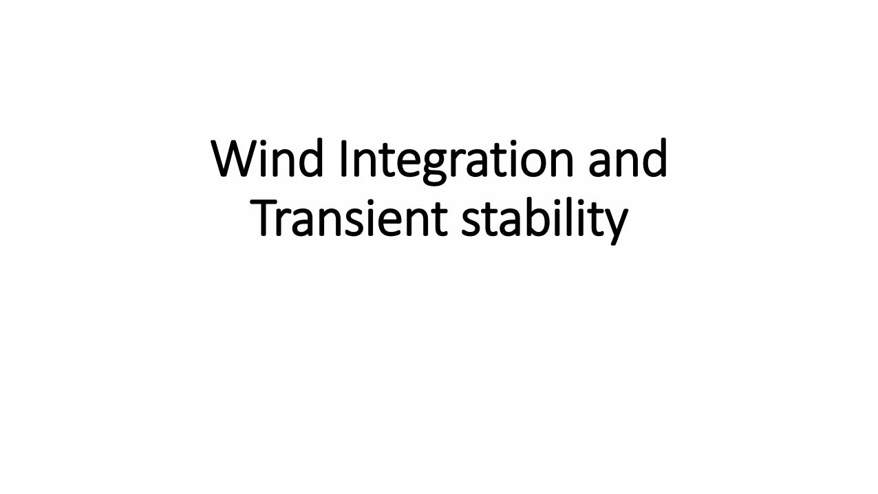
Types of Wind Generators
Figure 1: Direct-in-line wind turbine system. [1]
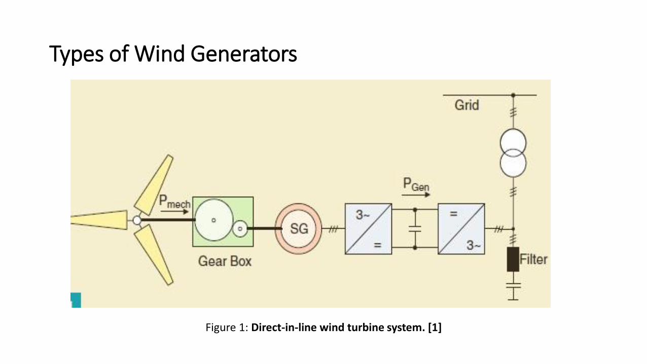
Types of Wind Generators
Figure 2: Doubly fed induction generator wind turbine system. [2]
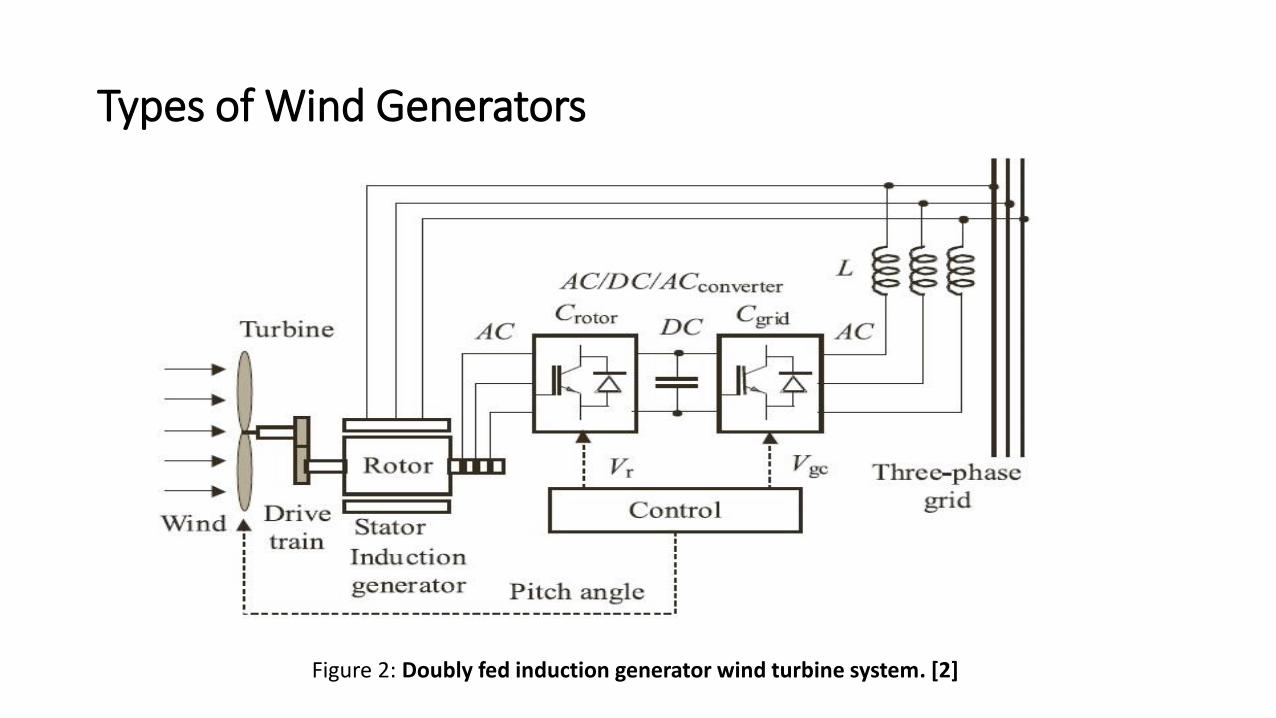
Modelling of DFIG
Figure 3: Conventional induction machine equivalent circuit [3]
Figure 4: Equivalent circuit of DFIG [3]
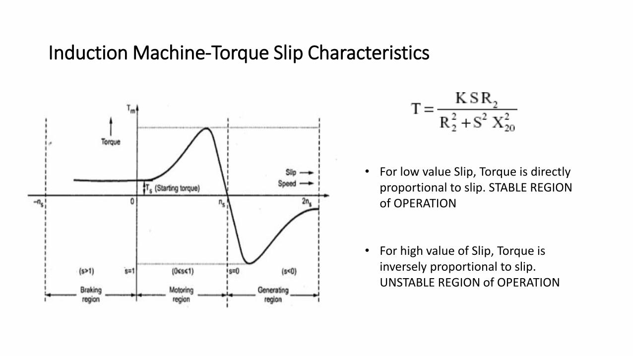
Induction Machine-Torque Slip Characteristics
• For low value Slip, Torque is directly proportional to slip. STABLE REGION of OPERATION
• For high value of Slip, Torque is inversely proportional to slip. UNSTABLE REGION of OPERATION
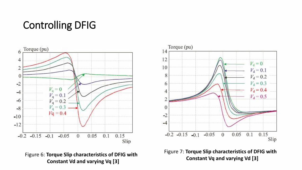
Controlling DFIG
Figure 6: Torque Slip characteristics of DFIG with Constant Vd and varying Vq [3]
Figure 7: Torque Slip characteristics of DFIG with Constant Vq and varying Vd [3]
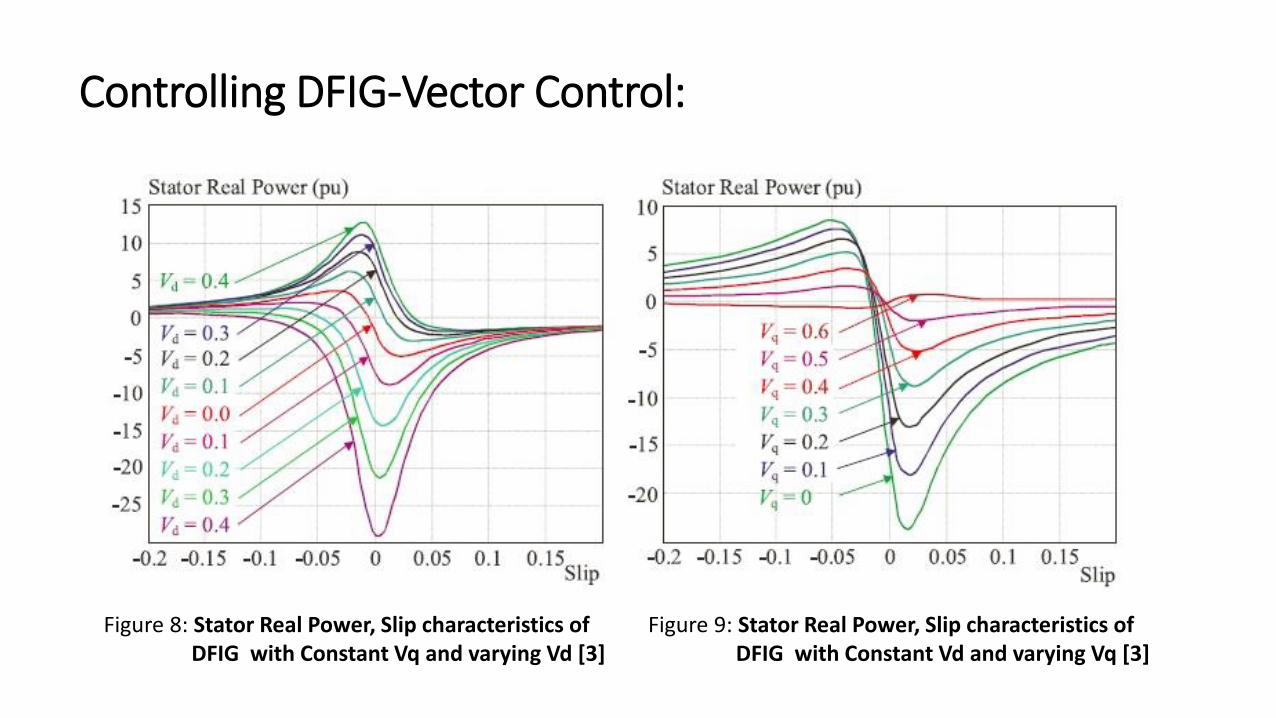
Controlling DFIG-Vector Control:
Figure 8: Stator Real Power, Slip characteristics of DFIG with Constant Vq and varying Vd [3]
Figure 9: Stator Real Power, Slip characteristics of DFIG with Constant Vd and varying Vq [3]
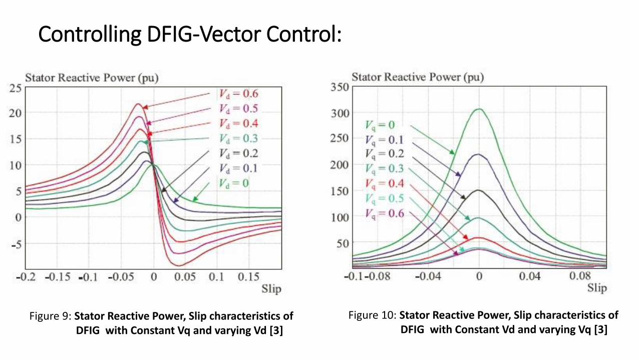
Controlling DFIG-Vector Control:
Figure 9: Stator Reactive Power, Slip characteristics of DFIG with Constant Vq and varying Vd [3]
Figure 10: Stator Reactive Power, Slip characteristics of DFIG with Constant Vd and varying Vq [3]
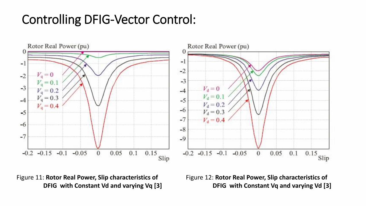
Controlling DFIG-Vector Control:
Figure 12: Rotor Real Power, Slip characteristics of DFIG with Constant Vq and varying Vd [3]
Figure 11: Rotor Real Power, Slip characteristics of DFIG with Constant Vd and varying Vq [3]
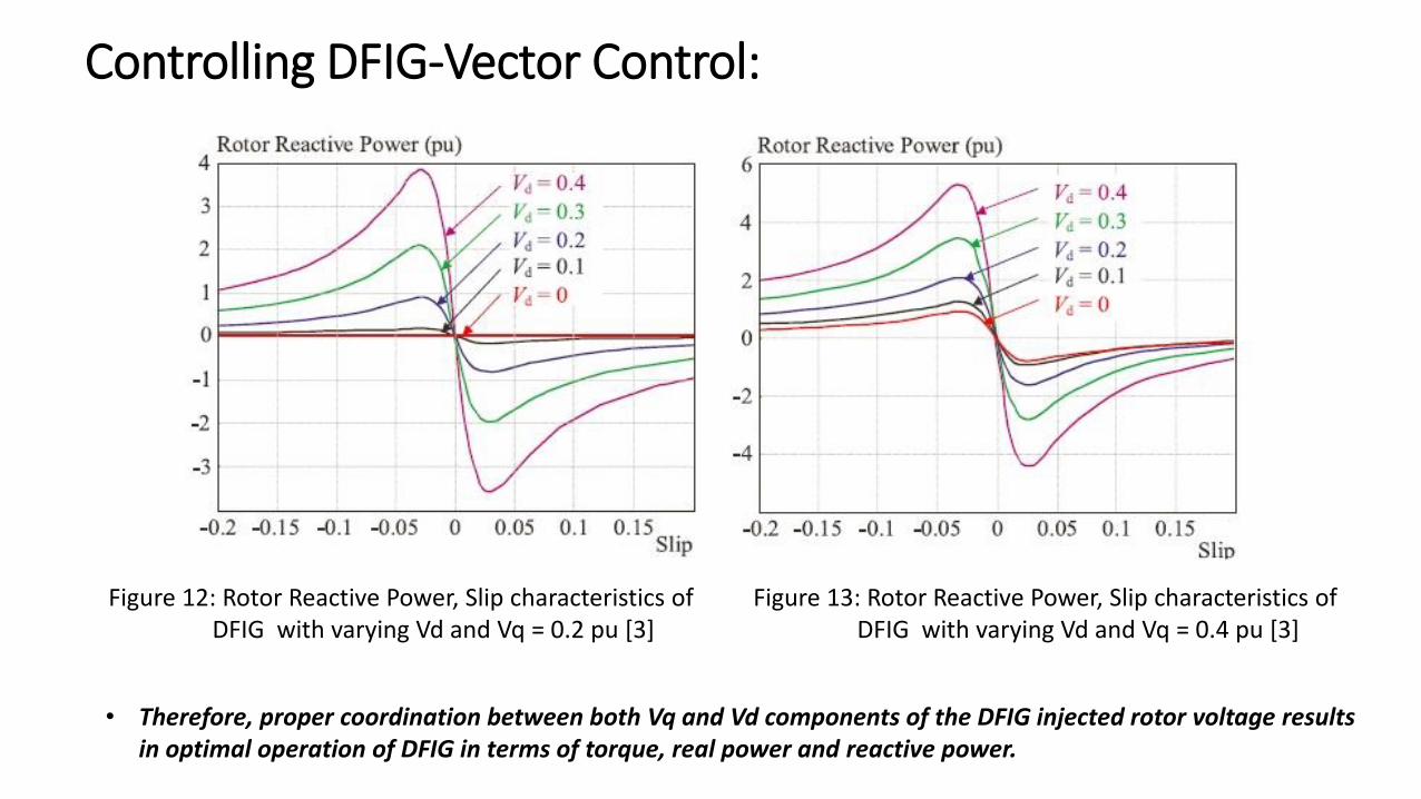
Controlling DFIG-Vector Control:
Figure 12: Rotor Reactive Power, Slip characteristics of DFIG with varying Vd and Vq = 0.2 pu [3]
Figure 13: Rotor Reactive Power, Slip characteristics of DFIG with varying Vd and Vq = 0.4 pu [3]
• Therefore, proper coordination between both Vq and Vd components of the DFIG injected rotor voltage results in optimal operation of DFIG in terms of torque, real power and reactive power.
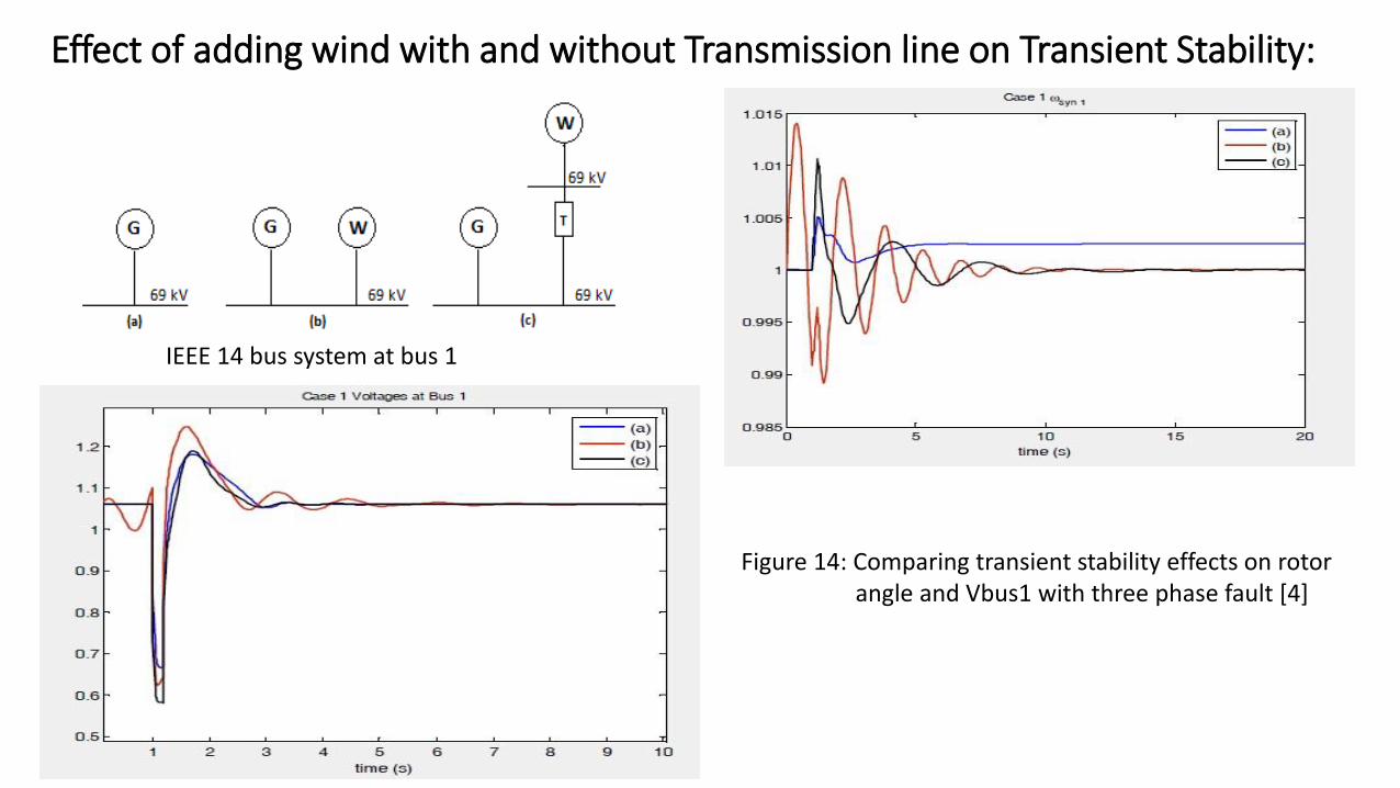
Effect of adding wind with and without Transmission line on Transient Stability:
IEEE 14 bus system at bus 1
Figure 14: Comparing transient stability effects on rotor angle and Vbus1 with three phase fault [4]
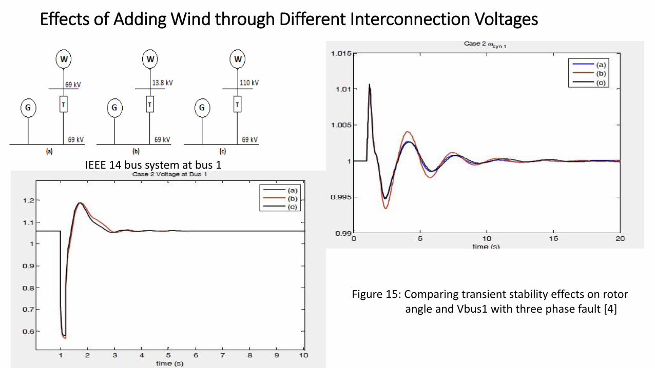
Effects of Adding Wind through Different Interconnection Voltages
IEEE 14 bus system at bus 1
Figure 15: Comparing transient stability effects on rotor angle and Vbus1 with three phase fault [4]
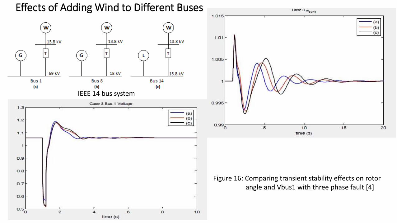
Effects of Adding Wind to Different Buses
IEEE 14 bus system
Figure 16: Comparing transient stability effects on rotor angle and Vbus1 with three phase fault [4]
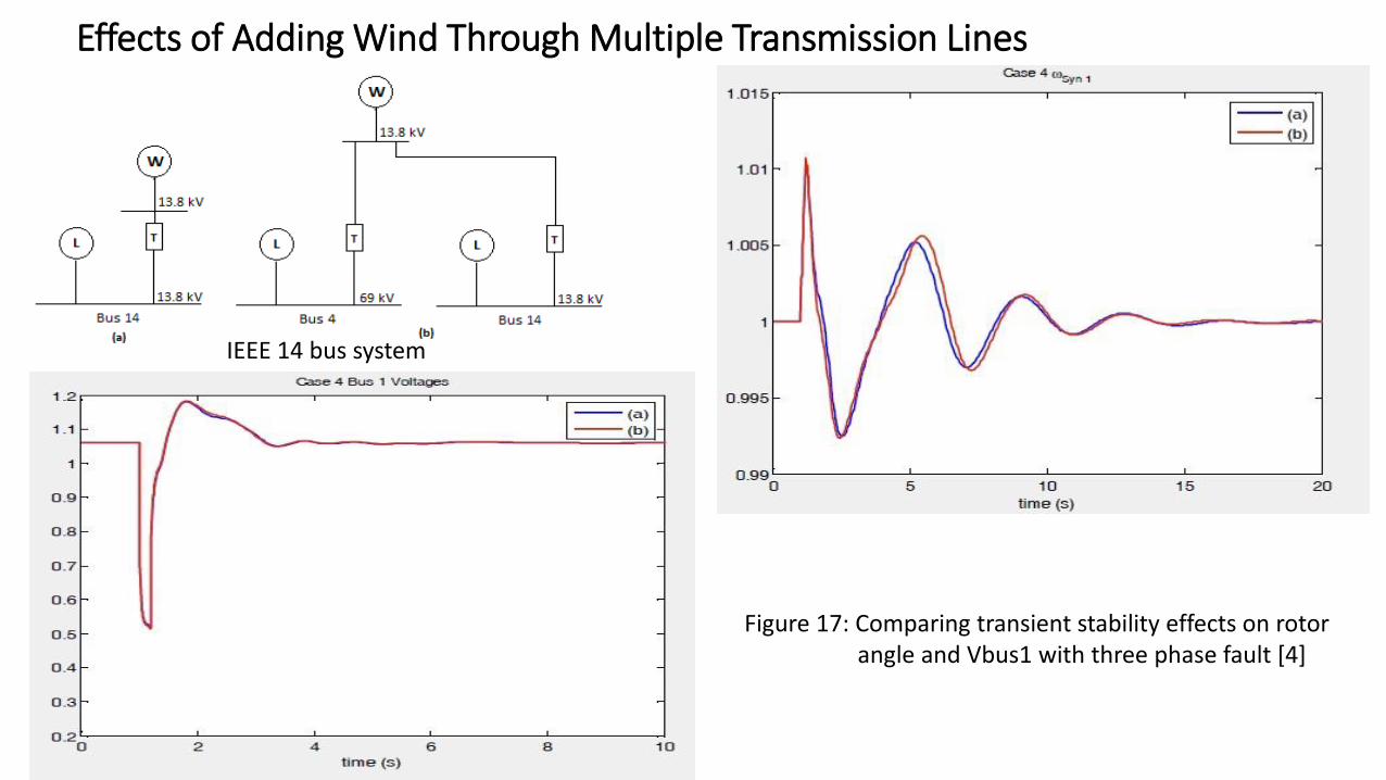
Effects of Adding Wind Through Multiple Transmission Lines
IEEE 14 bus system
Figure 17: Comparing transient stability effects on rotor angle and Vbus1 with three phase fault [4]
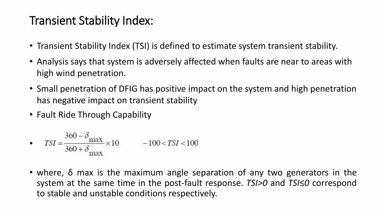
Transient Stability Index:
• Transient Stability Index (TSI) is defined to estimate system transient stability.
• Analysis says that system is adversely affected when faults are near to areas with high wind penetration.
• Small penetration of DFIG has positive impact on the system and high penetration has negative impact on transient stability
• Fault Ride Through Capability
•
• where, δ max is the maximum angle separation of any two generators in thesystem at the same time in the post-fault response. TSI>0 and TSI≤0 correspondto stable and unstable conditions respectively.
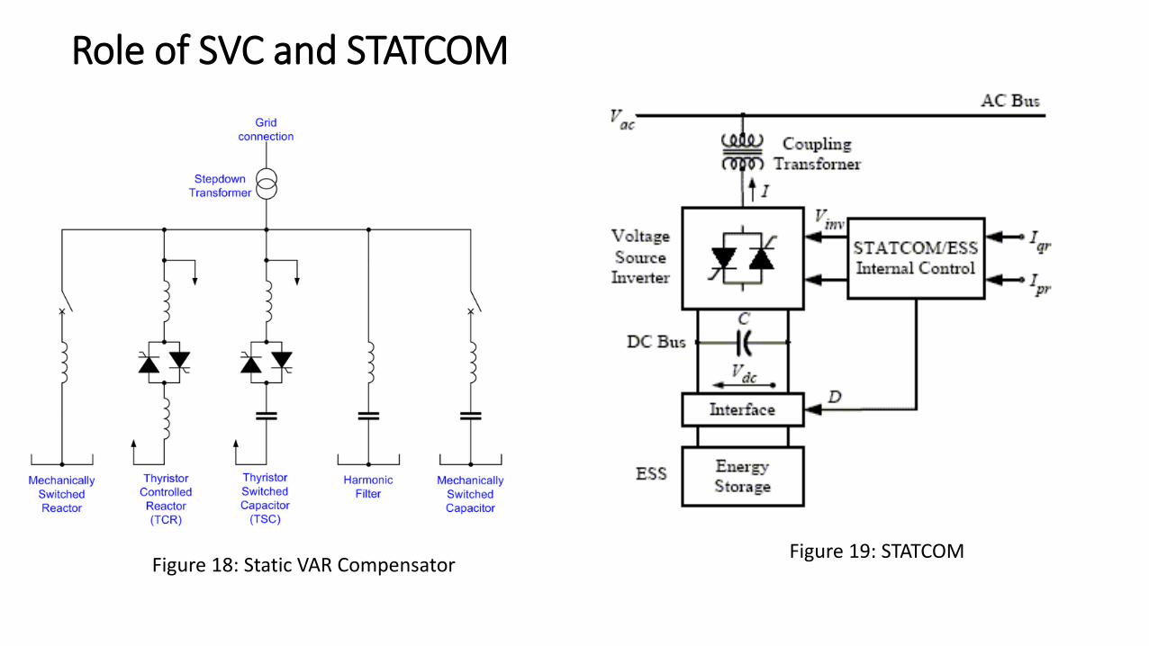
Role of SVC and STATCOM
Figure 18: Static VAR CompensatorFigure 19: STATCOM
Role of SVC and STATCOM
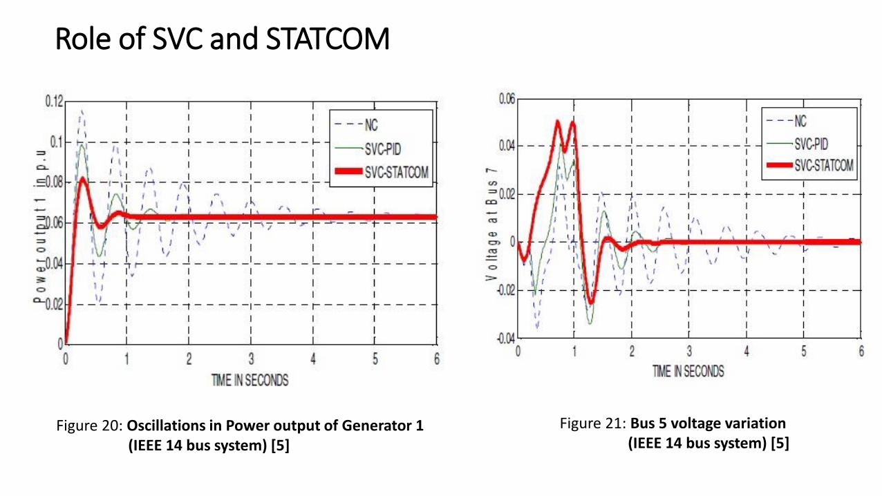
Figure 20: Oscillations in Power output of Generator 1 (IEEE 14 bus system) [5]
Figure 21: Bus 5 voltage variation(IEEE 14 bus system) [5]
Role of STATCOM
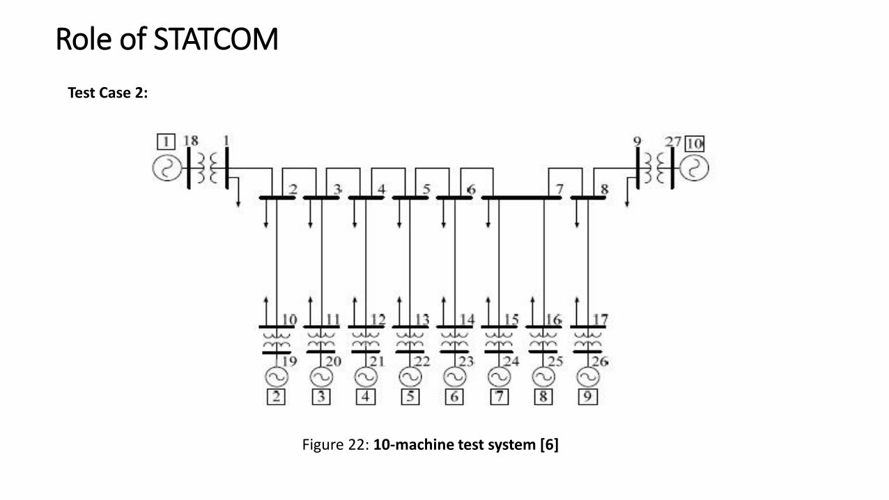
Test Case 2:
Figure 22: 10-machine test system [6]
Role of STATCOM
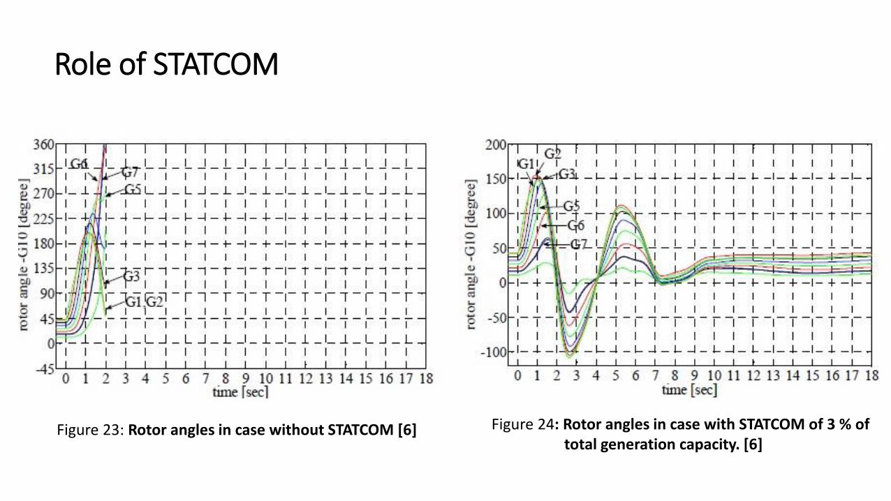
Figure 23: Rotor angles in case without STATCOM [6] Figure 24: Rotor angles in case with STATCOM of 3 % of total generation capacity. [6]
Role of STATCOM
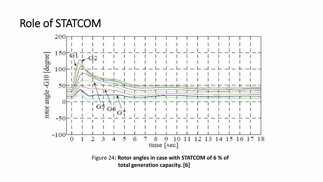
Figure 24: Rotor angles in case with STATCOM of 6 % of total generation capacity. [6]
Role of STATCOM
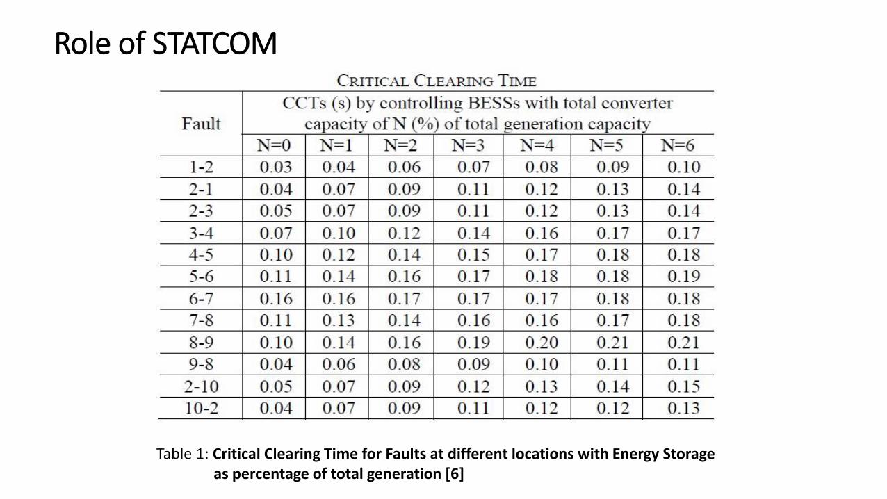
Table 1: Critical Clearing Time for Faults at different locations with Energy Storageas percentage of total generation [6]

Thank You


