Download - Wave Optics Theory MM
genius PHYSICS by Pradeep Kshetrapal
Only for students of genius academy Jamanipali, Maxwell classes Korba, and Gupta classes Kusmunda.
Wave Optics 1
Light Propagation.
Light is a form of energy which generally gives the sensation of sight. (1) Different theories
(2) Optical phenomena explained (√√√√) or not explained (××××) by the different theories of light
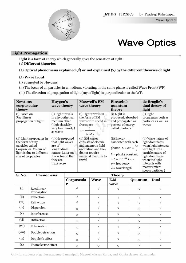
(3) Wave front
(i) Suggested by Huygens
(ii) The locus of all particles in a medium, vibrating in the same phase is called Wave Front (WF)
(iii) The direction of propagation of light (ray of light) is perpendicular to the WF.
Newtons corpuscular theory
Huygen’s wave theory
Maxwell’s EM wave theory
Einstein’s quantum theory
de-Broglie’s dual theory of light
(i) Based on Rectilinear propagation of light
(i) Light travels in a hypothetical medium ether (high elasticity very low density) as waves
(i) Light travels in the form of EM waves with speed in free space
00
1
εµ=c
(i) Light is produced, absorbed and propagated as packets of energy called photons
(i) Light propagates both as particles as well as waves
(ii) Light propagates in the form of tiny particles called Corpuscles. Colour of light is due to different size of corpuscles
(ii) He proposed that light waves are of longitudinal nature. Later on it was found that they are transverse
(ii) EM waves consists of electric and magnetic field oscillation and they do not require material medium to travel
(ii) Energy associated with each
photon λ
νhc
hE ==
h = planks constant
sec-106.634 J−×=
ν = frequency λ = wavelength
(ii) Wave nature of light dominates when light interacts with light. The particle nature of light dominates when the light interacts with matter (micro-scopic particles )
S. No. Phenomena Theory
Corpuscular
Wave E.M. wave
Quantum Dual
(i) Rectilinear Propagation
√ √ √ √ √
(ii) Reflection √ √ √ √ √
(iii) Refraction √ √ √ √ √
(iv) Dispersion × √ √ × √
(v) Interference × √ √ × √
(vi) Diffraction × √ √ × √
(vii) Polarisation × √ √ × √
(viii) Double refraction × √ √ × √
(ix) Doppler’s effect × √ √ × √
(x) Photoelectric effect × × × √ √
genius PHYSICS by Pradeep Kshetrapal 2 Wave Optics
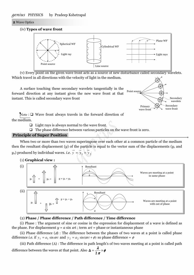
(iv) Types of wave front
(v) Every point on the given wave front acts as a source of new disturbance called secondary wavelets. Which travel in all directions with the velocity of light in the medium.
A surface touching these secondary wavelets tangentially in the
forward direction at any instant gives the new wave front at that instant. This is called secondary wave front
Note : � Wave front always travels in the forward direction of
the medium.
� Light rays is always normal to the wave front. � The phase difference between various particles on the wave front is zero.
Principle of Super Position.
When two or more than two waves superimpose over each other at a common particle of the medium then the resultant displacement (y) of the particle is equal to the vector sum of the displacements (y1 and
y2) produced by individual waves. i.e. 21 yyy +=
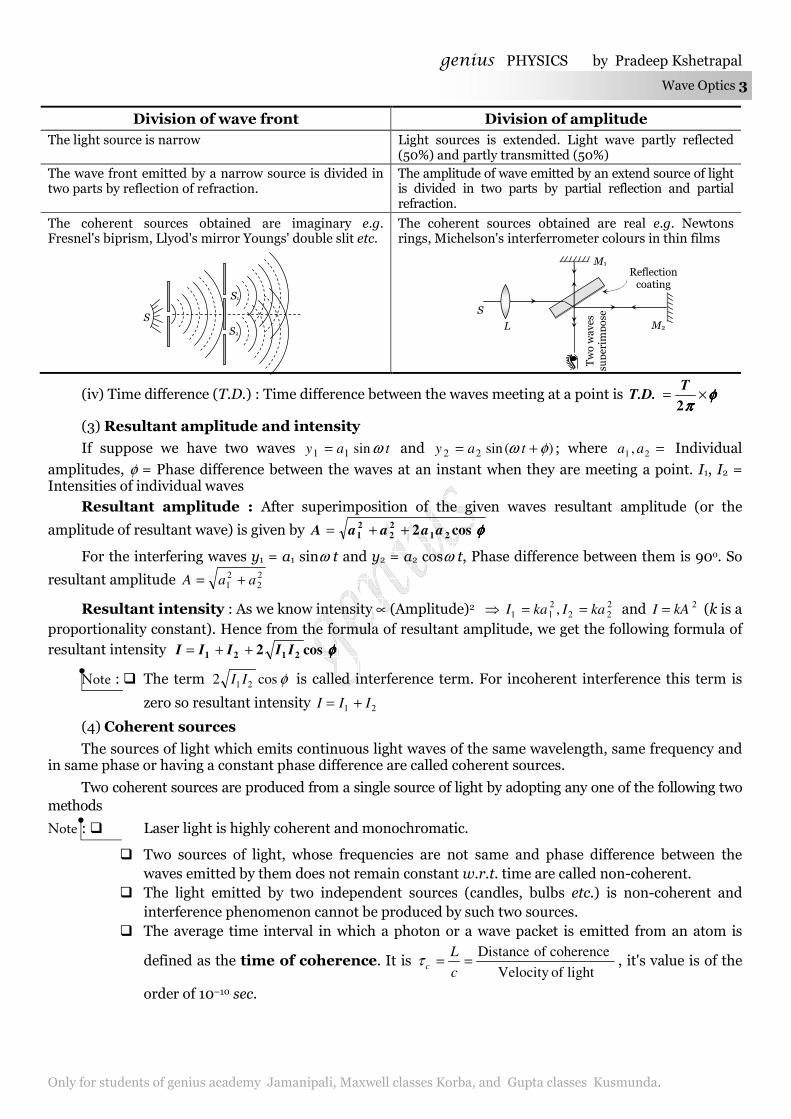
(1) Graphical view :
(i)
(ii)
(2) Phase / Phase difference / Path difference / Time difference (i) Phase : The argument of sine or cosine in the expression for displacement of a wave is defined as
the phase. For displacement y = a sin ω t ; term ω t = phase or instantaneous phase
(ii) Phase difference (φ) : The difference between the phases of two waves at a point is called phase difference i.e. if tay ωsin11 = and )(sin22 φω += tay so phase difference = φ
(iii) Path difference (∆) : The difference in path length’s of two waves meeting at a point is called path
difference between the waves at that point. Also φφφφππππ
λλλλ×=
2∆∆∆∆
Point source
Light ray
Spherical WF
Line source
Cylindrical WF
Plane WF
Light rays
Primary wave front
Secondary wave front
Secondary wavelets
Point source
y1 y2 = y = y1 + y2 +
Resultant
1
2 Waves are meeting at a point
in same phase
y1 y2 =
y = y1 – y2
+
Resultant 1
2
Waves are meeting at a point with out of phase
genius PHYSICS by Pradeep Kshetrapal
Only for students of genius academy Jamanipali, Maxwell classes Korba, and Gupta classes Kusmunda.
Wave Optics 3
(iv) Time difference (T.D.) : Time difference between the waves meeting at a point is φφφφππππ
×=2
TT.D.
(3) Resultant amplitude and intensity
If suppose we have two waves tay ωsin11 = and )(sin22 φω += tay ; where =21 , aa Individual
amplitudes, φ = Phase difference between the waves at an instant when they are meeting a point. I1, I2 = Intensities of individual waves
Resultant amplitude : After superimposition of the given waves resultant amplitude (or the
amplitude of resultant wave) is given by φφφφcos2 21
2
2
2
1 aaaaA ++=
For the interfering waves y1 = a1 sinω t and y2 = a2 cosω t, Phase difference between them is 90o. So
resultant amplitude 22
21 aaA +=
Resultant intensity : As we know intensity ∝ (Amplitude)2 ⇒ 222
211 , kaIkaI == and 2kAI = (k is a
proportionality constant). Hence from the formula of resultant amplitude, we get the following formula of resultant intensity φφφφcos2 2121 IIIII ++=
Note : � The term φcos2 21 II is called interference term. For incoherent interference this term is
zero so resultant intensity 21 III +=
(4) Coherent sources
The sources of light which emits continuous light waves of the same wavelength, same frequency and in same phase or having a constant phase difference are called coherent sources.
Two coherent sources are produced from a single source of light by adopting any one of the following two methods
Note : � Laser light is highly coherent and monochromatic.
� Two sources of light, whose frequencies are not same and phase difference between the waves emitted by them does not remain constant w.r.t. time are called non-coherent.
� The light emitted by two independent sources (candles, bulbs etc.) is non-coherent and interference phenomenon cannot be produced by such two sources.
� The average time interval in which a photon or a wave packet is emitted from an atom is
defined as the time of coherence. It is lightof Velocity
coherenceof Distance==
c
Lcτ , it's value is of the
order of 10–10 sec.
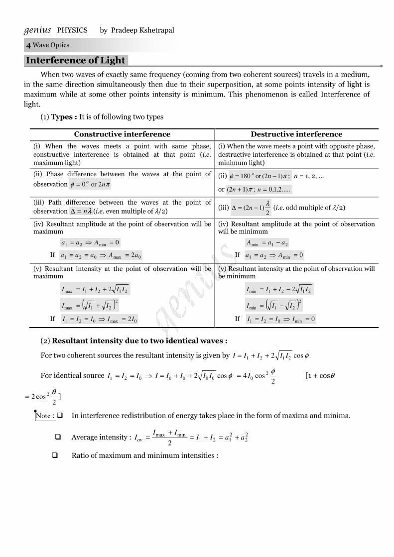
Division of wave front Division of amplitude
The light source is narrow Light sources is extended. Light wave partly reflected (50%) and partly transmitted (50%)
The wave front emitted by a narrow source is divided in two parts by reflection of refraction.
The amplitude of wave emitted by an extend source of light is divided in two parts by partial reflection and partial refraction.
The coherent sources obtained are imaginary e.g. Fresnel's biprism, Llyod's mirror Youngs' double slit etc.
The coherent sources obtained are real e.g. Newtons rings, Michelson's interferrometer colours in thin films
S
S1
S2
Reflection coating
M1
S
L
Two waves
superim
pose
M2
genius PHYSICS by Pradeep Kshetrapal 4 Wave Optics
Interference of Light.
When two waves of exactly same frequency (coming from two coherent sources) travels in a medium, in the same direction simultaneously then due to their superposition, at some points intensity of light is maximum while at some other points intensity is minimum. This phenomenon is called Interference of light.
(1) Types : It is of following two types
Constructive interference Destructive interference
(i) When the waves meets a point with same phase, constructive interference is obtained at that point (i.e. maximum light)
(i) When the wave meets a point with opposite phase, destructive interference is obtained at that point (i.e. minimum light)
(ii) Phase difference between the waves at the point of
observation πφ no 2or0= (ii) ;)12(or180 πφ −= no n = 1, 2, ...
or ;)12( π+n .....2,1,0=n
(iii) Path difference between the waves at the point of observation λn=∆ (i.e. even multiple of λ/2) (iii)
2)12(
λ−=∆ n (i.e. odd multiple of λ/2)
(iv) Resultant amplitude at the point of observation will be maximum
0min21 =⇒= Aaa
If 0max021 2aAaaa =⇒==
(iv) Resultant amplitude at the point of observation will be minimum
21min aaA −=
If 0min21 =⇒= Aaa
(v) Resultant intensity at the point of observation will be maximum
2121max 2 IIIII ++=
( )2
21max III +=
If 0max021 2IIIII =⇒==
(v) Resultant intensity at the point of observation will be minimum
2121min 2 IIIII −+=
( )2
21min III −=
If 0min021 =⇒== IIII
(2) Resultant intensity due to two identical waves :
For two coherent sources the resultant intensity is given by φcos2 2121 IIIII ++=
For identical source 021 III == ⇒ φcos2 0000 IIIII ++= 2
cos4 20
φI= [1 + cosθ
2cos2 2 θ
= ]
Note : � In interference redistribution of energy takes place in the form of maxima and minima.
� Average intensity : 22
2121
minmax
2aaII
IIIav +=+=
+=
� Ratio of maximum and minimum intensities :
genius PHYSICS by Pradeep Kshetrapal
Only for students of genius academy Jamanipali, Maxwell classes Korba, and Gupta classes Kusmunda.
Wave Optics 5
2
21
21
2
21
21
2
21
21
2
21
21
min
max
1/
1/
1/
1/
−
+=
−
+=
−
+=
−
+=
aa
aa
aa
aa
II
II
II
II
I
Ialso
−
+
==
1
1
min
max
min
max
2
1
2
1
I
I
I
I
a
a
I
I
� If two waves having equal intensity (I1 = I2 = I0) meets at two locations P and Q with path
difference ∆1 and ∆2 respectively then the ratio of resultant intensity at point P and Q will be
∆
∆
==
λπ
λπ
φ
φ
22
12
22
12
cos
cos
2cos
2cos
Q
P
I
I
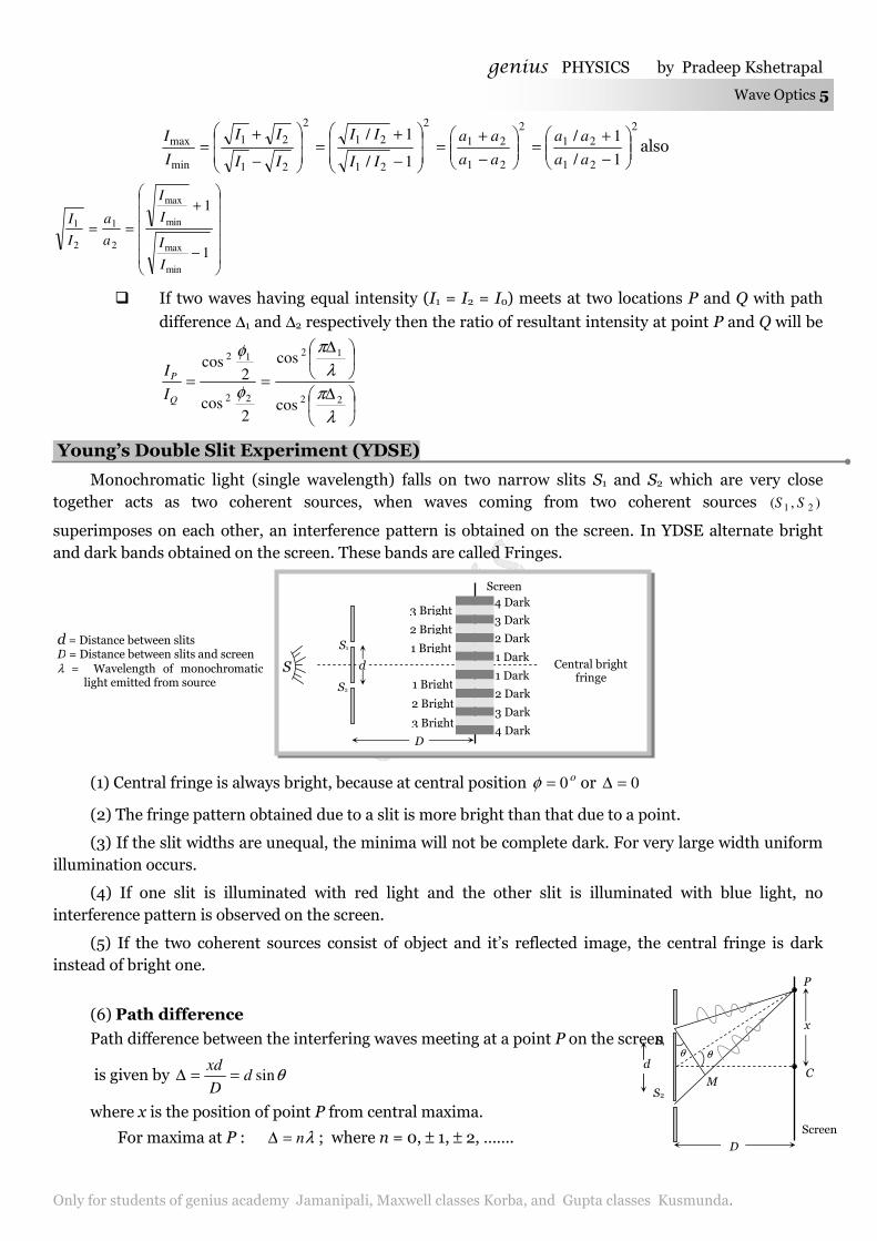
Young’s Double Slit Experiment (YDSE)
Monochromatic light (single wavelength) falls on two narrow slits S1 and S2 which are very close together acts as two coherent sources, when waves coming from two coherent sources ),( 21 SS
superimposes on each other, an interference pattern is obtained on the screen. In YDSE alternate bright and dark bands obtained on the screen. These bands are called Fringes.
(1) Central fringe is always bright, because at central position o0=φ or 0=∆
(2) The fringe pattern obtained due to a slit is more bright than that due to a point.
(3) If the slit widths are unequal, the minima will not be complete dark. For very large width uniform illumination occurs.
(4) If one slit is illuminated with red light and the other slit is illuminated with blue light, no interference pattern is observed on the screen.
(5) If the two coherent sources consist of object and it’s reflected image, the central fringe is dark instead of bright one.
(6) Path difference
Path difference between the interfering waves meeting at a point P on the screen
is given by θsindD
xd==∆
where x is the position of point P from central maxima.
For maxima at P : λn=∆ ; where n = 0, ± 1, ± 2, …….
Central bright fringe
(or Central
S
S1
S2
d
D
Screen
4 Dark
1 Dark
2 Dark
3 Dark
4 Dark
3 Dark
2 Dark
1 Dark
1 Bright
2 Bright
3 Bright
1 Bright
2 Bright
3 Bright
d = Distance between slits D = Distance between slits and screen λ = Wavelength of monochromatic
light emitted from source
S1
S2
d
Screen
D
C M
θ θ
x
P
genius PHYSICS by Pradeep Kshetrapal 6 Wave Optics
and For minima at P : 2
)12( λ−=∆
n; where n = ± 1, ± 2, …….
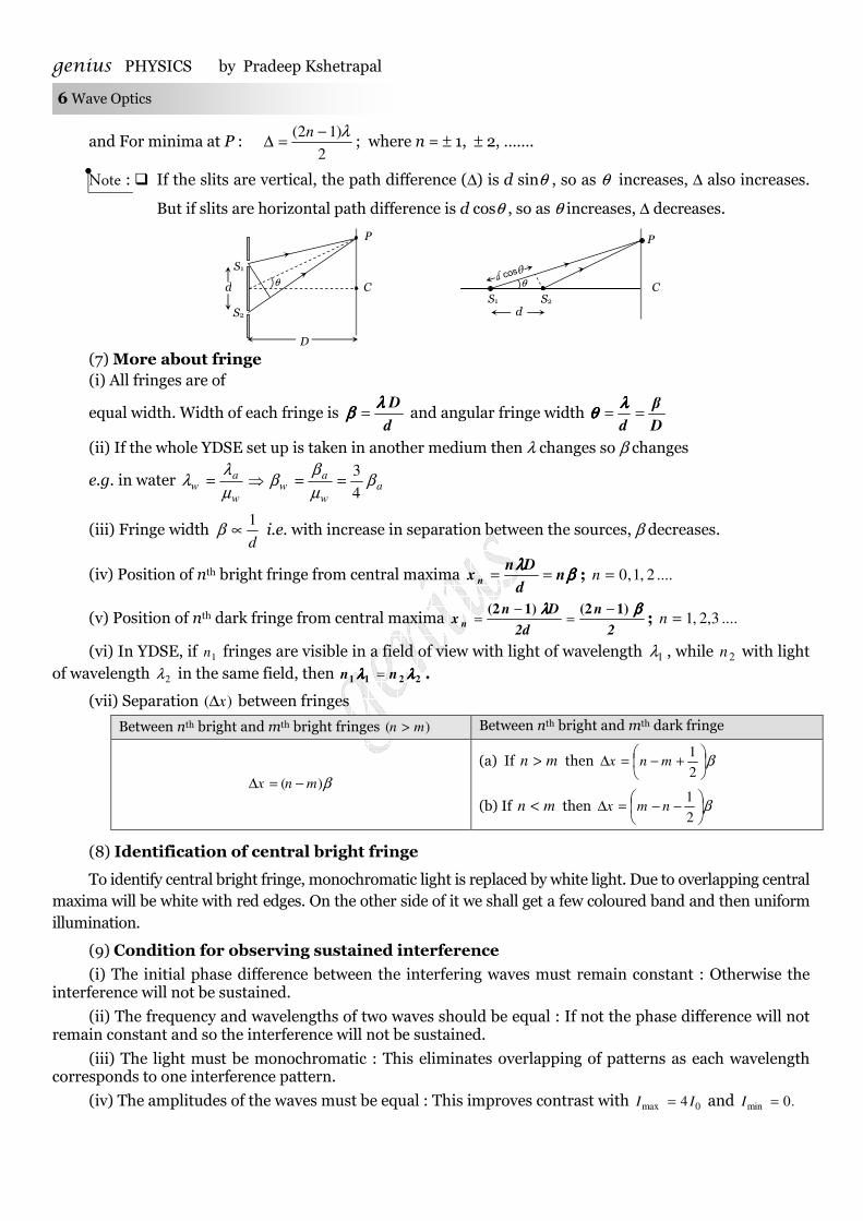
Note : � If the slits are vertical, the path difference (∆) is d sinθ , so as θ increases, ∆ also increases.
But if slits are horizontal path difference is d cosθ , so as θ increases, ∆ decreases.
(7) More about fringe (i) All fringes are of
equal width. Width of each fringe is d
Dλλλλββββ = and angular fringe width
D
β
d==
λλλλθθθθ
(ii) If the whole YDSE set up is taken in another medium then λ changes so β changes
e.g. in water aw
aw
w
aw β
µβ
βµλ
λ4
3==⇒=
(iii) Fringe width d
1∝β i.e. with increase in separation between the sources, β decreases.
(iv) Position of nth bright fringe from central maxima ββββλλλλ
nd
Dnx
n== ; ....2,1,0=n
(v) Position of nth dark fringe from central maxima 2
n
2d
Dnx
n
ββββλλλλ 1)(21)(2 −=
−= ; ....3,2,1=n
(vi) In YDSE, if 1n fringes are visible in a field of view with light of wavelength 1λ , while 2n with light of wavelength 2λ in the same field, then 2211 λλλλλλλλ nn = .
(vii) Separation )( x∆ between fringes
Between nth bright and mth bright fringes )( mn > Between nth bright and mth dark fringe
β)( mnx −=∆
(a) If mn > then β
+−=∆
2
1mnx
(b) If mn < then β
−−=∆
2
1nmx
(8) Identification of central bright fringe
To identify central bright fringe, monochromatic light is replaced by white light. Due to overlapping central maxima will be white with red edges. On the other side of it we shall get a few coloured band and then uniform illumination.
(9) Condition for observing sustained interference
(i) The initial phase difference between the interfering waves must remain constant : Otherwise the interference will not be sustained.
(ii) The frequency and wavelengths of two waves should be equal : If not the phase difference will not remain constant and so the interference will not be sustained.
(iii) The light must be monochromatic : This eliminates overlapping of patterns as each wavelength corresponds to one interference pattern.
(iv) The amplitudes of the waves must be equal : This improves contrast with 0max 4 II = and .0min =I
S1
S2
d
D
C θ
P
θ
S2 S1
P
d
C
genius PHYSICS by Pradeep Kshetrapal
Only for students of genius academy Jamanipali, Maxwell classes Korba, and Gupta classes Kusmunda.
Wave Optics 7
(v) The sources must be close to each other : Otherwise due to small fringe width
∝
d
1β the eye can
not resolve fringes resulting in uniform illumination.
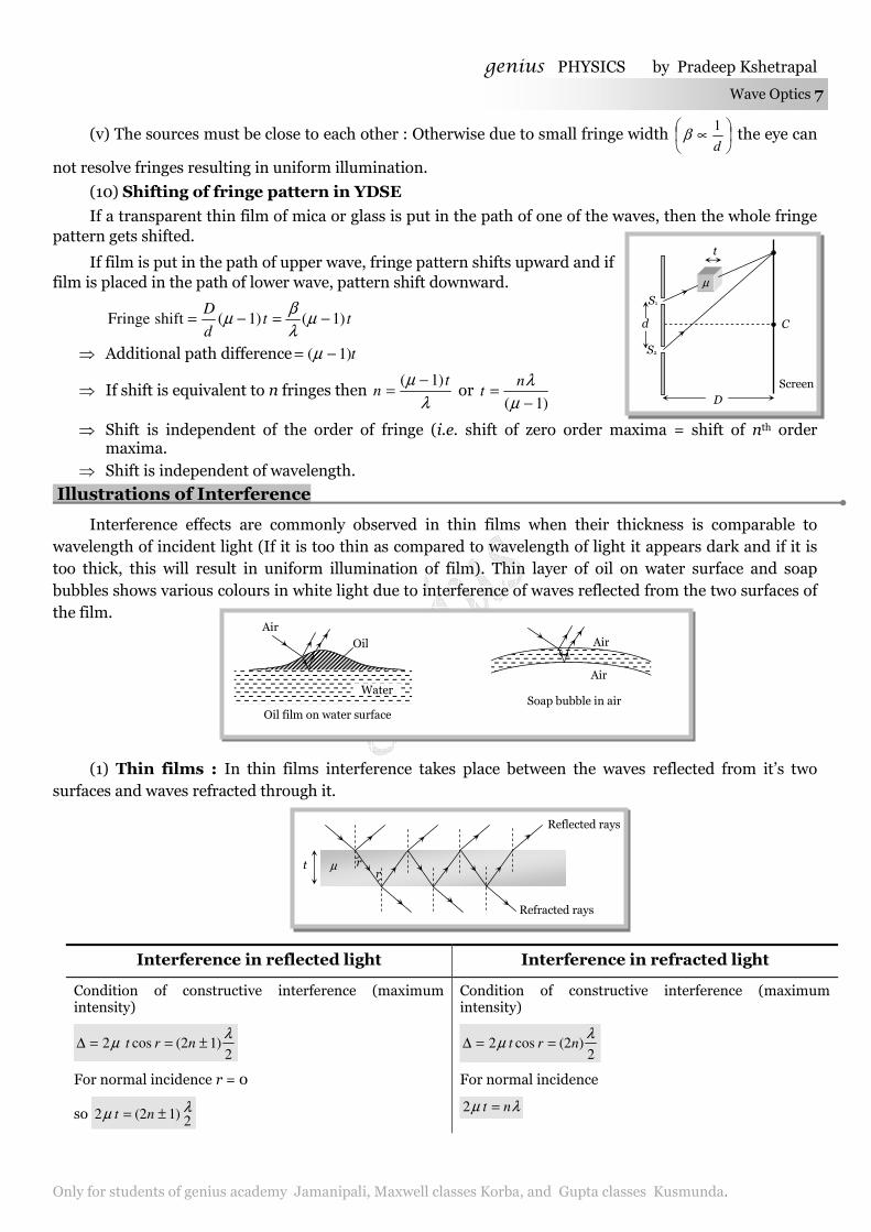
(10) Shifting of fringe pattern in YDSE
If a transparent thin film of mica or glass is put in the path of one of the waves, then the whole fringe pattern gets shifted.
If film is put in the path of upper wave, fringe pattern shifts upward and if film is placed in the path of lower wave, pattern shift downward.
ttd
D)1()1(shift Fringe −=−= µ
λβ
µ
⇒ Additional path difference t)1( −= µ
⇒ If shift is equivalent to n fringes then λ
µ tn
)1( −= or
)1( −=
µλn
t
⇒ Shift is independent of the order of fringe (i.e. shift of zero order maxima = shift of nth order maxima.
⇒ Shift is independent of wavelength.
Illustrations of Interference
Interference effects are commonly observed in thin films when their thickness is comparable to wavelength of incident light (If it is too thin as compared to wavelength of light it appears dark and if it is too thick, this will result in uniform illumination of film). Thin layer of oil on water surface and soap bubbles shows various colours in white light due to interference of waves reflected from the two surfaces of the film.
(1) Thin films : In thin films interference takes place between the waves reflected from it’s two surfaces and waves refracted through it.
Interference in reflected light Interference in refracted light
Condition of constructive interference (maximum intensity)
2)12(cos2
λµ ±==∆ nrt
For normal incidence r = 0
so λµ2
)12(2 ±= nt
Condition of constructive interference (maximum intensity)
2)2(cos2
λµ nrt ==∆
For normal incidence
λµ nt =2
Oil Air
Water
Oil film on water surface
Air
Air
Soap bubble in air
S1
S2
d
Screen
D
µ
t
C
t µ
Refracted rays
Reflected rays
r r
genius PHYSICS by Pradeep Kshetrapal 8 Wave Optics
Condition of destructive interference (minimum intensity)
2)2(cos2
λµ nrt ==∆
For normal incidence λµ nt =2
Condition of destructive interference (minimum intensity)
2)12(cos2
λµ ±==∆ nrt
For normal incidence 2
)12(2λ
µ ±= nt
Doppler’s Effect in Light
The phenomenon of apparent change in frequency (or wavelength) of the light due to relative motion between the source of light and the observer is called Doppler’s effect.
If =ν actual frequency, ='ν Apparent frequency, v = speed of source w.r.t stationary observer, c = speed
of light
Source of light moves towards the stationary
observer (v << c)
Source of light moves away from the
stationary observer (v << c)
(i) Apparent frequency
+=′
c
v1νν and
Apparent wavelength
−=′
c
v1λλ
(i) Apparent frequency
−=′
c
v1νν and
Apparent wavelength
+=′
c
v1λλ
(ii) Doppler’s shift : Apparent wavelength < actual wavelength,
So spectrum of the radiation from the source of light shifts towards the red end of spectrum. This is called Red shift
Doppler’s shift c
v.λλλλλλλλ =∆
(ii) Doppler’s shift : Apparent wavelength > actual wavelength,
So spectrum of the radiation from the source of light shifts towards the violet end of spectrum. This is called Violet shift
Doppler’s shift c
v.λλλλλλλλ =∆
Note : � Doppler’s shift )( λ∆ and time period of rotation (T) of a star relates as T
r
c
πλλ
2×=∆ ; r = radius
of star.
Applications of Doppler effect
(i) Determination of speed of moving bodies (aeroplane, submarine etc) in RADAR and SONAR.
(ii) Determination of the velocities of stars and galaxies by spectral shift.
(iii) Determination of rotational motion of sun.
(iv) Explanation of width of spectral lines.
(v) Tracking of satellites. (vi) In medical sciences in echo cardiogram, sonography etc.
Concepts
� The angular thickness of fringe width is defined as dD
λβδ == , which is independent of the screen distance D.
� Central maxima means the maxima formed with zero optical path difference. It may be formed anywhere on the screen.
� All the wavelengths produce their central maxima at the same position.
� The wave with smaller wavelength from its maxima before the wave with longer wavelength.
� The first maxima of violet colour is closest and that for the red colour is farthest.
genius PHYSICS by Pradeep Kshetrapal
Only for students of genius academy Jamanipali, Maxwell classes Korba, and Gupta classes Kusmunda.
Wave Optics 9
� Fringes with blue light are thicker than those for red light.
� In an interference pattern, whatever energy disappears at the minimum, appears at the maximum.
� In YDSE, the nth maxima always comes before the nth minima.
� In YDSE, the ratio min
max
I
I is maximum when both the sources have same intensity.
� For two interfering waves if initial phase difference between them is φ0 and phase difference due to path difference
between them is φ '. Then total phase difference will be ∆∆∆∆λλλλππππ
φφφφφφφφφφφφφφφφ 00002
+=+=0
' .
� Sometimes maximm number of maximas or minimas are asked in the question which can be obtained on the screen. For this we use the fact that value of sin θ (or cos θ) can't be greater than 1. For example in the first case when the slits are vertical
d
nλθ =sin (for maximum intensity)
Q sin θ ≯1 ∴ d
nλ≯ 1 or n ≯
λd
Suppose in some question d/λ comes out say 4.6, then total number of maximuas on the screen will be 9. Corresponding to 3,2,1,0 ±±±=n and 4± .
� Shape of wave front If rays are parallel, wave front is plane. If rays are converging wave front is spherical of decreasing radius. If rays are
diverging wave front is spherical of increasing radius.
Example: 1 If two light waves having same frequency have intensity ratio 4 : 1 and they interfere, the ratio of
maximum to minimum intensity in the pattern will be
(a) 9 : 1 (b) 3 : 1 (c) 25 : 9 (d) 16 : 25
Solution: (a) By using 1
9
11
4
11
4
1
1
22
2
1
2
1
min
max =
−
+=
−
+
=
I
I
I
I
I
I.
Example: 2 In Young’s double slit experiment using sodium light (λ = 5898Å), 92 fringes are seen. If given colour (λ = 5461Å) is used, how many fringes will be seen
(a) 62 (b) 67 (c) 85 (d) 99
Solution: (d) By using 2211 λλ nn = ⇒ 5461589892 2 ×=× n ⇒ 992 =n
Example: 3 Two beams of light having intensities I and 4I interfere to produce a fringe pattern on a screen. The
phase difference between the beams is 2
π at point A and π at point B. Then the difference between the
resultant intensities at A and B is
(a) 2I (b) 4I (c) 5I (d) 7I
Solution: (b) By using φcos2 2121 IIIII ++=
At point A : Resultant intensity IIIIII A 52
cos424 =×++=π
At point B : Resultant intensity IIIIIIB =×++= πcos424 . Hence the difference III BA 4=−=
Examples
genius PHYSICS by Pradeep Kshetrapal 10 Wave Optics
Example: 4 If two waves represented by ty ωsin41 = and
+=
3sin32
πωty interfere at a point, the amplitude of the
resulting wave will be about [MP PMT 2000]
(a) 7 (b) 6 (c) 5 (d) 3.
Solution: (b) By using φcos2 2122
21 aaaaA ++= ⇒ 637
3cos342)3()4( 22 ≈=××++=
πA .
Example: 5 Two waves being produced by two sources 1S and 2S . Both sources have zero phase difference and
have wavelength λ. The destructive interference of both the waves will occur of point P if )( 21 PSPS −
has the value
[MP PET 1987]
(a) 5λ (b) λ4
3 (c) 2λ (d) λ
2
11
Solution: (d) For destructive interference, path difference the waves meeting at P (i.e. )21 PSPS − must be odd
multiple of λ/2. Hence option (d) is correct.
Example: 6 Two interfering wave (having intensities are 9I and 4I) path difference between them is 11 λ. The resultant intensity at this point will be
(a) I (b) 9 I (c) 4 I (d) 25 I
Solution: (d) Path difference φπλ
×=∆2
⇒ πλλπ
22112
=× i.e. constructive interference obtained at the same
point
So, resultant intensity IIIIIIR 25)49()( 2221 =+=+= .
Example: 7 In interference if 81
144
min
max =I
I then what will be the ratio of amplitudes of the interfering wave
(a) 81
144 (b)
1
7 (c)
7
1 (d)
9
12
Solution: (b) By using 1
7
15
12
19
12
181
144
181
144
1
1
min
max
min
max
2
1 =
−
+=
−
+=
−
+
=
I
I
I
I
a
a
Example: 8 Two interfering waves having intensities x and y meets a point with time difference 3T/2. What will be the resultant intensity at that point
(a) )( yx + (b) )( xyyx ++ (c) xyyx 2++ (d) xy
yx
2
+
Solution: (c) Time difference T.D. φπ
×=2
T⇒ φ
π×=
22
3 TT⇒ ;3πφ = This is the condition of constructive
interference.
So resultant intensity .2)()( 2221 xyyxyxIIIR ++=+=+=
Example: 9 In Young’s double-slit experiment, an interference pattern is obtained on a screen by a light of wavelength 6000 Å, coming from the coherent sources 1S and 2S . At certain point P on the screen
third dark fringe is formed. Then the path difference PSPS 21 − in microns is [EAMCET 2003]
(a) 0.75 (b) 1.5 (c) 3.0 (d) 4.5
Solution: (b) For dark fringe path difference ;2
)12(λ
−=∆ n here n = 3 and λ = 6000 × 10–10 m

genius PHYSICS by Pradeep Kshetrapal
Only for students of genius academy Jamanipali, Maxwell classes Korba, and Gupta classes Kusmunda.
Wave Optics 11
So .5.110152
106)132(
77
micronsm =×=×
×−×=∆ −−
Example: 10 In a Young’s double slit experiment, the slit separation is 1 mm and the screen is 1 m from the slit. For a monochromatic light of wavelength 500 nm, the distance of 3rd minima from the central maxima is
(a) 0.50 mm (b) 1.25 mm (c) 1.50 mm (d) 1.75 mm
Solution: (b) Distance of nth minima from central maxima is given as d
Dnx
2
)12( λ−=
So here mmx 25.1102
110500)132(3
9
=×
×××−×=
−
−
Example: 11 The two slits at a distance of 1 mm are illuminated by the light of wavelength 7105.6 −× m. The interference fringes are observed on a screen placed at a distance of 1 m. The distance between third dark fringe and fifth bright fringe will be
[NCERT 1982; MP PET 1995; BVP 2003]
(a) 0.65 mm (b) 1.63 mm (c) 3.25 mm (d) 4.88 mm
Solution: (b) Distance between nth bright and mth dark fringe (n > m) is given as
d
Dmnmnx
λβ
+−=
+−=
2
1
2
1
⇒ mmx 63.1101
1105.6
2
135
3
7
=×
×××
+−=
−
−
.
Example: 12 The slits in a Young’s double slit experiment have equal widths and the source is placed symmetrically relative to the slits. The intensity at the central fringes is I0. If one of the slits is closed, the intensity at this point will be[MP PMT 1999]
(a) I0 (b) 4/0I (c) 2/0I (d) 04 I
Solution: (b) By using 2
cos42 φ
IIR = {where I = Intensity of each wave}
At central position φ = 0o, hence initially I0 = 4I.
If one slit is closed, no interference takes place so intensity at the same location will be I only i.e.
intensity become s th4
1 or
4
0I.
Example: 13 In double slit experiment, the angular width of the fringes is 0.20° for the sodium light (λ = 5890 Å). In order to increase the angular width of the fringes by 10%, the necessary change in the wavelength is
(a) Increase of 589 Å (b) Decrease of 589 Å (c) Increase of 6479 Å (d) Zero
Solution: (a) By using d
λθ = ⇒
2
1
2
1
λλ
θθ
= ⇒ 2
5890
)20.0of%1020.0(
20.0
λ=
+o
o
⇒ 2
5890
22.0
20.0
λ= ⇒ 64792 =λ
So increase in wavelength = 6479 – 5890 = 589 Å. Example: 14 In Young’s experiment, light of wavelength 4000 Å is used, and fringes are formed at 2 metre distance and has a
fringe width of 0.6 mm. If whole of the experiment is performed in a liquid of refractive index 1.5, then width of fringe will be
[MP PMT 1994, 97]
(a) 0.2 mm (b) 0.3 mm (c) 0.4 mm (d) 1.2 mm
Solution: (c) µ
ββ air
medium = ⇒ mmmedium 4.05.1
6.0==β .
Example: 15 Two identical sources emitted waves which produces intensity of k unit at a point on screen where
path difference is λ. What will be intensity at a point on screen at which path difference is λ/4 [RPET 1996]
(a) 4
k (b)
2
k (c) k (d) Zero
genius PHYSICS by Pradeep Kshetrapal 12 Wave Optics
Solution: (b) By using phase difference )(2
∆=λπ
φ
For path difference λ, phase difference πφ 21 = and for path difference λ/4, phase difference φ2 = π/2.
Also by using 2
cos42
0
φII = ⇒
)2/(cos
)2/(cos
22
12
2
1
φ
φ=
I
I ⇒⇒⇒⇒
2/1
1
2
2/cos
)2/2(cos
2
2
2
=
=
ππ
I
k ⇒ .
22
kI =
Example: 16 A thin mica sheet of thickness 6102 −× m and refractive index (µ = 1.5) is introduced in the path of the first wave. The wavelength of the wave used is 5000Å. The central bright maximum will shift [CPMT 1999]
(a) 2 fringes upward (b) 2 fringes downward (c) 10 fringes upward (d) None of these
Solution: (a) By using shift tp
x )1( −=∆ µλ
⇒ ββ
2102)15.1(105000
6
10=××−
×=∆ −
−x
Since the sheet is placed in the path of the first wave, so shift will be 2 fringes upward.
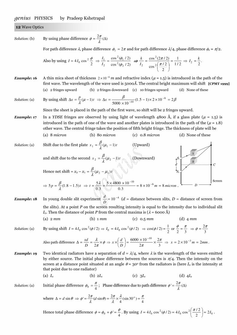
Example: 17 In a YDSE fringes are observed by using light of wavelength 4800 Å, if a glass plate (µ = 1.5) is introduced in the path of one of the wave and another plates is introduced in the path of the (µ = 1.8) other wave. The central fringe takes the position of fifth bright fringe. The thickness of plate will be
(a) 8 micron (b) 80 micron (c) 0.8 micron (d) None of these
Solution: (a) Shift due to the first plate tx )1( 11 −= µλβ
(Upward)
and shift due to the second tx )1( 22 −= µλβ
(Downward)
Hence net shift = x2 – x1 t)( 12 µµλβ
−=
⇒ tp )5.18.1(5 −=λβ
⇒ micronmt 81083.0
1048005
3.0
5 610
=×=××
== −−λ
.
Example: 18 In young double slit experiment 410
−=D
d (d = distance between slits, D = distance of screen from
the slits). At a point P on the screen resulting intensity is equal to the intensity due to individual slit I0. Then the distance of point P from the central maxima is (λ = 6000 Å)
(a) 2 mm (b) 1 mm (c) 0.5 mm (d) 4 mm
Solution: (a) By using shift )2/(cos4 20 φII = ⇒ )2/(cos4 2
00 φII = ⇒ 2
1)2/cos( =φ or
32
πφ= ⇒
3
2πφ =
Also path difference φπλ
×==∆2D
xd ⇒
3
2
2
106000 10 ππ
××
=
×
−
D
dx ⇒ .2102 3 mmmx =×= −
Example: 19 Two identical radiators have a separation of d = λ/4, where λ is the wavelength of the waves emitted by either source. The initial phase difference between the sources is π/4. Then the intensity on the screen at a distance point situated at an angle θ = 30o from the radiators is (here I0 is the intensity at that point due to one radiator)
(a) I0 (b) 2I0 (c) 3I0 (d) 4I0
Solution: (a) Initial phase difference 4
0
πφ = ; Phase difference due to path difference )(
2' ∆=
λπ
φ
where θsind=∆ ⇒ 4
)30(sin4
2)sin(
2'
πλλπ
θλπ
φ =×== od
Hence total phase difference 4
'0
φφφφ =+= . By using 0
20
20 2
2
2/cos4)2/(cos4 IIII =
==
πφ .
S1
S2
d
Screen
D
C
1
2
genius PHYSICS by Pradeep Kshetrapal
Only for students of genius academy Jamanipali, Maxwell classes Korba, and Gupta classes Kusmunda.
Wave Optics 13
Example: 20 In YDSE a source of wavelength 6000 Å is used. The screen is placed 1 m from the slits. Fringes formed on the screen, are observed by a student sitting close to the slits. The student's eye can distinguish two neighbouring fringes. If they subtend an angle more than 1 minute of arc. What will be the maximum distance between the slits so that the fringes are clearly visible
(a) 2.06 mm (b) 2.06 cm (c) 2.06 × 10⁻³ mm (d) None of these
Solution: (a) According to given problem angular fringe width 60180 ×
≥=πλ
θd
]60180
'1 As[ rad×
=π
i.e. π
60180106 7 ×××<
−
d i.e. md 31006.2 −×< ⇒ mmd 06.2max =
Example: 21 the maximum intensity in case of interference of n identical waves, each of intensity I0, if the interference is (i) coherent and (ii) incoherent respectively are
(a) 002 , nIIn (b) 0
20 , InnI (c) 00 , InI (d) 00
2 )1(, InIn −
Solution: (a) In case of interference of two wave φcos2 2121 IIIII ++=
(i) In case of coherent interference φ does not vary with time and so I will be maximum when 1maxcos ==φ
i.e. 2212121max )(2)( IIIIIII co +=++=
So for n identical waves each of intensity I0 022
02
00max )(......)()( InInIII co ==++=
(ii)In case of incoherent interference at a given point, φ varies randomly with time, so 0)(cos =avφ
and hence 21)( III IncoR +=
So in case of n identical waves 000 .......)( nIIII IncoR =++=
Example: 22 The width of one of the two slits in a Young's double slit experiment is double of the other slit. Assuming that the amplitude of the light coming from a slit is proportional to the slit width. The ratio of the maximum to the minimum intensity in interference pattern will be
(a) a
1 (b)
1
9 (c)
1
2 (d)
2
1
Solution: (b) AAAA 32max =+= and AAAA =−= 2min . Also 1
9322
min
max
min
max =
=
=
A
A
A
A
I
I
Example: 23 A star is moving towards the earth with a speed of sm /105.4 6× . If the true wavelength of a certain line
in the spectrum received from the star is 5890 Å, its apparent wavelength will be about
]/103[8 smc ×=
[MP PMT 1999]
(a) 5890 Å (b) 5978 Å (c) 5802 Å (d) 5896 Å
Solution: (c) By using
−=
c
v1' λλ ⇒ Å5802
103
105.415890'
8
6
=
×
×−=λ .
Example: 24 Light coming from a star is observed to have a wavelength of 3737 Å, while its real wavelength is 3700
Å. The speed of the star relative to the earth is [Speed of light sm /103 8×= ] [MP PET 1997]
(a) sm /103 5× (b) sm /103 6× (c) sm /107.3 7× (d) sm /107.3 6×
Solution: (b) By using c
vλλ =∆ ⇒ (3737-3700)=
8103
3700×
×v
⇒ smv /103 6×= .
Example: 25 Light from the constellation Virgo is observed to increase in wavelength by 0.4%. With respect to Earth the constellation is [MP PMT 1994, 97; MP PET 2003]
genius PHYSICS by Pradeep Kshetrapal 14 Wave Optics
(a) Moving away with velocity sm /102.1 6× (b) Coming closer with velocity sm /102.1 6×
(c) Moving away with velocity sm /104 6× (d) Coming closer with velocity sm /104 6×
Solution: (a) By using ;c
v=
∆
λλ
where 100
4.0=
∆
λλ
and c = 3 × 10⁸ m/s ⇒ 8
103100
4.0
×=
v ⇒ v = 1.2 × 10⁶ m/s
Since wavelength is increasing i.e. it is moving away.
In YDSE, distance between the slits is 2 × 10⁻³ m, slits are illuminated by a light of wavelength 2000Å –9000 Å. In the field of view at a distance of 10–3 m from the central position which wavelength will be observe. Given distance between slits and screen is 2.5 m
(a) 40000 Å (b) 4500 Å (c) 5000 Å (d) 5500 Å
Solution : (b) d
Dnx
λ= ⇒
5.2
1021033
×
××==
−−
nnD
xdλ Å
nm
n
8000108 7
=×
⇒−
For n = 1, 2, 3....... λ = 8000 Å, 4000 Å, .........3
8000Å
Hence only option (a) is correct.
I is the intensity due to a source of light at any point P on the screen. If light reaches the point P via two different paths (a) direct (b) after reflection from a plane mirror then path difference between
two paths is 3λ/2, the intensity at P is
(a) I (b) Zero (c) 2I (d) 4I
Solution : (d) Reflection of light from plane mirror gives additional path difference of λ/2 between two waves
∴ Total path difference λλλ
222
3=+=
Which satisfies the condition of maxima. Resultant intensity .4)(2 III =+=
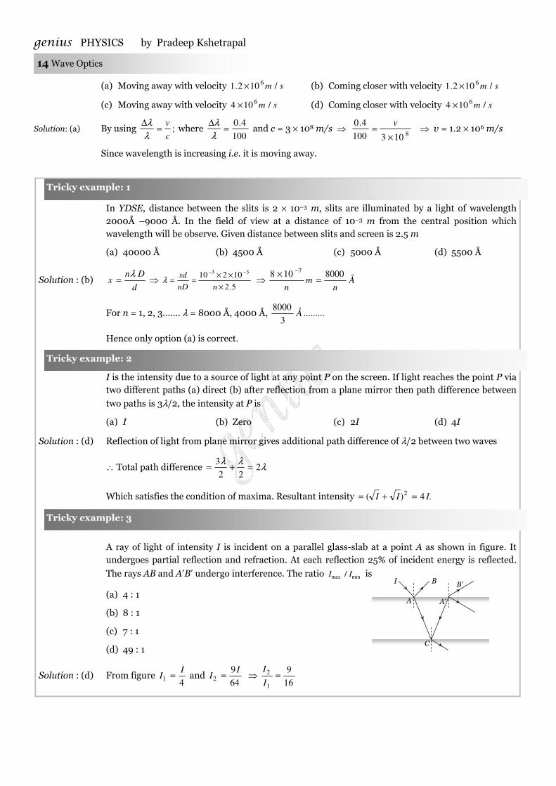
A ray of light of intensity I is incident on a parallel glass-slab at a point A as shown in figure. It undergoes partial reflection and refraction. At each reflection 25% of incident energy is reflected.
The rays AB and A′B′ undergo interference. The ratio minmax / II is
(a) 4 : 1
(b) 8 : 1
(c) 7 : 1
(d) 49 : 1
Solution : (d) From figure 4
1
II = and
64
92
II = ⇒
16
9
1
2 =I
I
Tricky example: 1
Tricky example: 2
Tricky example: 3
B′ B I
C
A A′
genius PHYSICS by Pradeep Kshetrapal
Only for students of genius academy Jamanipali, Maxwell classes Korba, and Gupta classes Kusmunda.
Wave Optics 15
By using 1
49
116
9
116
9
1
1
1
2
1
2
min
max =
−
+=
−
+
=
I
I
I
I
I
I
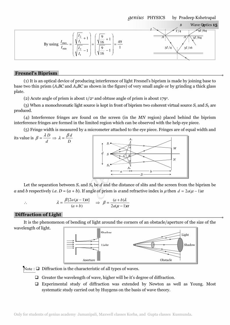
Fresnel's Biprism.
(1) It is an optical device of producing interference of light Fresnel's biprism is made by joining base to base two thin prism (A1BC and A2BC as shown in the figure) of very small angle or by grinding a thick glass plate.
(2) Acute angle of prism is about 1/2o and obtuse angle of prism is about 179o.
(3) When a monochromatic light source is kept in front of biprism two coherent virtual source S1 and S2 are produced.
(4) Interference fringes are found on the screen (in the MN region) placed behind the biprism interference fringes are formed in the limited region which can be observed with the help eye piece.
(5) Fringe width is measured by a micrometer attached to the eye piece. Fringes are of equal width and
its value is d
Dλβ = ⇒
D
dβλ =
Let the separation between S1 and S2 be d and the distance of slits and the screen from the biprism be
a and b respectively i.e. D = (a + b). If angle of prism is α and refractive index is µ then αµ )1(2 −= ad
∴ )(
])1(2[
ba
a
+
−=
αµβλ ⇒
αµλ
β)1(2
)(
−+
=a
ba
Diffraction of Light.
It is the phenomenon of bending of light around the corners of an obstacle/aperture of the size of the wavelength of light.
Note : � Diffraction is the characteristic of all types of waves.
� Greater the wavelength of wave, higher will be it’s degree of diffraction.
� Experimental study of diffraction was extended by Newton as well as Young. Most systematic study carried out by Huygens on the basis of wave theory.
Light
Shadow
Aperture
Light
Shadow
Obstacle
I I /4
3I /4 3I /16
3I /64
9I /64
A
B B ′
A ′
S
α
α
S2
S1
C B
A2
A1
D
d
M
N
b a
genius PHYSICS by Pradeep Kshetrapal 16 Wave Optics
� The minimum distance at which the observer should be from the obstacle to observe the
diffraction of light of wavelength λ around the obstacle of size d is given by λ4
2dx = .
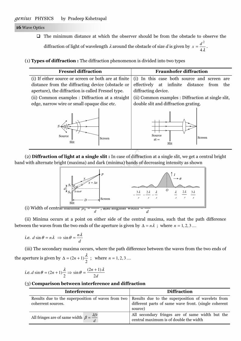
(1) Types of diffraction : The diffraction phenomenon is divided into two types
Fresnel diffraction Fraunhofer diffraction
(i) If either source or screen or both are at finite distance from the diffracting device (obstacle or aperture), the diffraction is called Fresnel type.
(i) In this case both source and screen are effectively at infinite distance from the diffracting device.
(ii) Common examples : Diffraction at a straight edge, narrow wire or small opaque disc etc.
(ii) Common examples : Diffraction at single slit, double slit and diffraction grating.
(2) Diffraction of light at a single slit : In case of diffraction at a single slit, we get a central bright band with alternate bright (maxima) and dark (minima) bands of decreasing intensity as shown
(i) Width of central maxima d
Dλβ
20 = ; and angular width
d
λ2=
(ii) Minima occurs at a point on either side of the central maxima, such that the path difference
between the waves from the two ends of the aperture is given by λn=∆ ; where ....3,2,1=n
i.e. λθ nd =sin d
nλθ =⇒ sin
(iii) The secondary maxima occurs, where the path difference between the waves from the two ends of
the aperture is given by 2
)12(λ
+=∆ n ; where ....3,2,1=n
i.e.d
nnd
2
)12(sin
2)12(sin
λθ
λθ
+=⇒+=
(3) Comparison between interference and diffraction
Interference Diffraction
Results due to the superposition of waves from two coherrent sources.
Results due to the superposition of wavelets from different parts of same wave front. (single coherent source)
All fringes are of same width d
Dλβ =
All secondary fringes are of same width but the central maximum is of double the width
Slit
S
Source Screen
Slit
Screen Source at ∞
Slit
x
Screen
x + ∆x
P
D
θ θ
d sinθ
S1
S2 d
I θ
d
λ3−
d
λ2−
d
λ−
d
λ
d
λ2
d
λ3
O

genius PHYSICS by Pradeep Kshetrapal
Only for students of genius academy Jamanipali, Maxwell classes Korba, and Gupta classes Kusmunda.
Wave Optics 17
d
Dλββ 220 ==
All fringes are of same intensity Intensity decreases as the order of maximum increases.
Intensity of all minimum may be zero Intensity of minima is not zero.
Positions of nth maxima and minima
d
Dnx n
λ=)Bright( ,
d
Dnx n
λ)12(Dark)( −=
Positions of nth secondary maxima and minima
d
Dnx n
λ)12(Bright)( += ,
d
Dnx n
λ=Dark)(
Path difference for nth maxima λn=∆ for nth secondary maxima
2)12(
λ+=∆ n
Path difference for nth minima λ)12( −=∆ n Path difference for nth minima λn=∆
(4) Diffraction and optical instruments : The objective lens of optical instrument like telescope or microscope etc. acts like a circular aperture. Due to diffraction of light at a circular aperture, a converging lens cannot form a point image of an object rather it produces a brighter disc known as Airy disc surrounded by alternate dark and bright concentric rings.
The angular half width of Airy discD
λθ
22.1== (where D = aperture of lens)
The lateral width of the image θf= (where f = focal length of the lens)
Note : � Diffraction of light limits the ability of optical instruments to form clear images of objects
when they are close to each other. (5) Diffraction grating : Consists of large number of equally spaced parallel slits. If light is incident
normally on a transmission grating, the diffraction of principle maxima (PM) is given by λθ nd =sin ; where d = distance between two consecutive slits and is called grating element.
Polarisation of Light
Light propagates as transverse EM waves. The magnitude of electric field is much larger as compared to magnitude of magnetic field. We generally prefer to describe light as electric field oscillations.
(1) Unpolarised light
The light having electric field oscillations in all directions in the plane perpendicular to the direction of propagation is called Unpolarised light. The oscillation may be resolved into horizontal and vertical component.
(2) Polarised light
The light having oscillations only in one plane is called Polarised or plane polarised light.
(i) The plane in which oscillation occurs in the polarised light is called plane of oscillation.
(ii) The plane perpendicular to the plane of oscillation is called plane of polarisation.
(iii) Light can be polarised by transmitting through certain crystals such as tourmaline or polaroids.
(3) Polaroids
θ
Light
II II I PM I PM Central maxim
R2 V2 R1 V1 V1 R1 V2 R2
Direction of propagation
Direction of propagation
Vertical oscillation Horizontal oscillation
genius PHYSICS by Pradeep Kshetrapal 18 Wave Optics
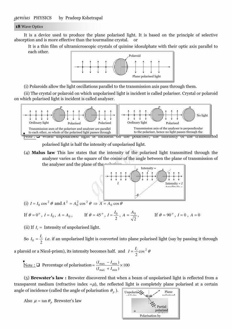
It is a device used to produce the plane polarised light. It is based on the principle of selective absorption and is more effective than the tourmaline crystal. or
It is a thin film of ultramicroscopic crystals of quinine idosulphate with their optic axis parallel to each other.
(i) Polaroids allow the light oscillations parallel to the transmission axis pass through them.
(ii) The crystal or polaroid on which unpolarised light is incident is called polariser. Crystal or polaroid on which polarised light is incident is called analyser.
Note : � When unpolarised light is incident on the polariser, the intensity of the transmitted
polarised light is half the intensity of unpolarised light.
(4) Malus law This law states that the intensity of the polarised light transmitted through the analyser varies as the square of the cosine of the angle between the plane of transmission of the analyser and the plane of the polariser.
(i) θ20 cosII = and θ22
02 cosAA = ⇒ θcos0AA =
If o0=θ , 0II = , 0AA = , If o45=θ , 2
0II = ,
2
0AA = , If o90=θ , 0=I , 0=A
(ii) If =iI Intensity of unpolarised light.
So 2
0iII = i.e. if an unpolarised light is converted into plane polarised light (say by passing it through
a plaroid or a Nicol-prism), its intensity becomes half. and θ2cos2
iII =
Note : � Percentage of polarisation 100)(
)(
minmax
minmax ×+
−=
II
II
(5) Brewster’s law : Brewster discovered that when a beam of unpolarised light is reflected from a
transparent medium (refractive index =µ), the reflected light is completely plane polarised at a certain
angle of incidence (called the angle of polarisation pθ ).
Also pθµ tan= Brewster’s law
Polaroid
Plane polarised light
P
Polarised light
Ordinary light
A
Polarised light
Transmission axes of the polariser and analyser are parallel to each other, so whole of the polarised light passes through
P
Polarised light
Ordinary light
A
No light
Transmission axis of the analyser is perpendicular to the polariser, hence no light passes through the
P Intensity = I0
Ii
A
θ
Intensity = I Amplitude =
θP θP
Unpolarised light
Plane polarised
Partial polarised
lightµ
Polarisation by reflection
genius PHYSICS by Pradeep Kshetrapal
Only for students of genius academy Jamanipali, Maxwell classes Korba, and Gupta classes Kusmunda.
Wave Optics 19
(i) For i < θP or i > θP
Both reflected and refracted rays becomes partially polarised
(ii) For glass ,57 oP ≈θ for water o
P 53≈θ
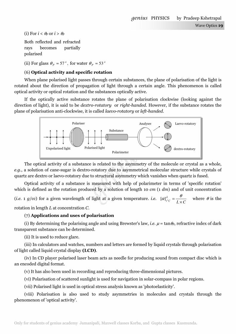
(6) Optical activity and specific rotation
When plane polarised light passes through certain substances, the plane of polarisation of the light is rotated about the direction of propagation of light through a certain angle. This phenomenon is called optical activity or optical rotation and the substances optically active.
If the optically active substance rotates the plane of polarisation clockwise (looking against the direction of light), it is said to be dextro-rotatory or right-handed. However, if the substance rotates the plane of polarisation anti-clockwise, it is called laevo-rotatory or left-handed.
The optical activity of a substance is related to the asymmetry of the molecule or crystal as a whole, e.g., a solution of cane-sugar is dextro-rotatory due to asymmetrical molecular structure while crystals of quartz are dextro or laevo-rotatory due to structural asymmetry which vanishes when quartz is fused.
Optical activity of a substance is measured with help of polarimeter in terms of 'specific rotation' which is defined as the rotation produced by a solution of length 10 cm (1 dm) and of unit concentration
(i.e. 1 g/cc) for a given wavelength of light at a given temperature. i.e. CLCto
×=
θα λ][ where θ is the
rotation in length L at concentration C.
(7) Applications and uses of polarisation
(i) By determining the polarising angle and using Brewster's law, i.e. µ = tanθP, refractive index of dark transparent substance can be determined.
(ii) It is used to reduce glare.
(iii) In calculators and watches, numbers and letters are formed by liquid crystals through polarisation of light called liquid crystal display (LCD).
(iv) In CD player polarised laser beam acts as needle for producing sound from compact disc which is an encoded digital format.
(v) It has also been used in recording and reproducing three-dimensional pictures.
(vi) Polarisation of scattered sunlight is used for navigation in solar-compass in polar regions.
(vii) Polarised light is used in optical stress analysis known as 'photoelasticity'.
(viii) Polarisation is also used to study asymmetries in molecules and crystals through the phenomenon of 'optical activity'.
dextro-rotatory
Laevo-rotatory
Polarimeter
Substance
Polariser Analyser
Unpolarised light Polarised light
genius PHYSICS by Pradeep Kshetrapal 20 Wave Optics
AAAAssignment
1. The dual nature of light is exhibited by [KCET 1999; AIIMS 2001; BHU 2001; Bihar CEE 2004]
(a) Diffraction and photoelectric effect (b) Diffraction and reflection
(c) Refraction and interference (d) Photoelectric effect
2. Huygen wave theory allows us to know [AFMC 2004]
(a) The wavelength of the wave (b) The velocity of the wave
(c) The amplitude of the wave (d) The propagation of wave fronts
3. When a beam of light is used to determine the position of an object, the maximum accuracy is achieved if the light is[AIIMS 2003]
(a) Polarised (b) Of longer wavelength (c) Of shorter wavelength (d) Of high intensity
4. Which of the following phenomenon does not show the wave nature of light [RPET 2003; MP PMT 2003]
(a) Diffraction (b) Interference (c) Refraction (d) Photoelectric effect
5. As a result of interference of two coherent sources of light, energy is [MP PMT 2002; KCET 2003]
(a) Increased
(b) Redistributed and the distribution does not vary with time
(c) Decreased
(d) Redistributed and the distribution changes with time
6. To demonstrate the phenomenon of interference, we require two sources which emit radiation [AIEEE 2003]
(a) Of the same frequency and having a definite phase relationship
(b) Of nearly the same frequency
(c) Of the same frequency
(d) Of different wavelengths
7. Consider the following statements
Assertion (A): Thin films such as soap bubble or a thin layer of oil on water show beautiful colours, when illuminated by white light.
Reason (R) : It happens due to the interference of light reflected from the upper surface of the thin film.
Of these statements [AIIMS 2002]
(a) Both A and R are true but R is a correct explanation of A (b) Both A and R are true but R is not a correct explanation of A
(c) A is true but R is false (d) A is false but R is true
(e) Both A and R are false
8. When light passes from one medium into another medium, then the physical property which does not change is
[CPMT 1990; MNR 1995; AMU 1995; UPSEAT 1999, 2000; MP PET 2002; RPET 1996, 2003; AFMC 1993, 98, 2003]
(a) Velocity (b) Wavelength (c) Frequency (d) Refractive index
9. The frequency of light ray having the wavelength 3000Å is [DPMT 2002]
(a) 13109 × cycles/sec (b) 1510 cycles/sec (c) 90 cycles/sec (d) 3000 cycles/sec
10. Two coherent sources of different intensities send waves which interfere. The ratio of maximum intensity to the minimum intensity is 25. The intensities of the sources are in the ratio [RPMT 1989; UPSEAT 2002]
(a) 25 : 1 (b) 5 : 1 (c) 9 : 4 (d) 25 : 16
11. What is the path difference of destructive interference [AIIMS 2002]
(a) nλ (b) n(λ + 1) (c) 2
)1( λ+n (d)
2
)12( λ+n
12. Two coherent monochromatic light beams of intensities I and 4I are superposed. The maximum and minimum possible intensities in the resulting beam are
[IIT-JEE 1988; AIIMS 1997; MP PMT 1997; MP PET 1999; KCET (Engg./Med.) 2000; MP PET 2002]
(a) 5I and I (b) 5I and 3I (c) 9I and I (d) 9I and 3I 13. Laser beams are used to measure long distance because [DCE 2001]
(a) They are monochromatic (b) They are highly polarised
Nature of light and interference of light
genius PHYSICS by Pradeep Kshetrapal
Only for students of genius academy Jamanipali, Maxwell classes Korba, and Gupta classes Kusmunda.
Wave Optics 21
(c) They are coherent (d) They have high degree of parallelism
14. Wave nature of light is verified by [RPET 2001]
(a) Interference (b) Photoelectric effect (c) Reflection (d) Refraction
15. If the wavelength of light in vacuum be λ, the wavelength in a medium of refractive index n will be [UPSEAT 2001; MP PET 2001]
(a) nλ (b) n
λ (c)
2n
λ (d) λ2n
16. Newton postulated his corpuscular theory on the basis of [UPSEAT 2001; KCET 2001]
(a) Newton’s rings (b) Colours of thin films
(c) Rectilinear propagation of light (d) Dispersion of white light
17. Two coherent sources of intensities. 1I and 2I produce an interference pattern. The maximum intensity in the interference
pattern will be [UPSEAT 2001; MP PET 2001]
(a) 21 II + (b) 22
21 II + (c) 2
21 )( II + (d) 221 )( II +
18. Which one among the following shows particle nature of light [CBSE PM/PD 2001]
(a) Photo electric effect (b) Interference (c) Refraction (d) Polarization
19. For constructive interference to take place between two monochromatic light waves of wavelength λ, the path difference should be
[MNR 1992; UPSEAT 2001]
(a) 4
)12(λ
−n (b) 2
)12(λ
−n (c) nλ (d) 2
)12(λ
+n
20. In a wave, the path difference corresponding to a phase difference of φ is [MP PET 2000]
(a) φλ
π2
(b) φλπ
(c) φπλ
2 (d) φ
πλ
21. A beam of monochromatic blue light of wavelength 4200Å in air travels in water, its wavelength in water will be [UPSEAT 2000]
(a) 2800Å (b) 5600Å (c) 3150Å (d) 4000Å
22. Wave front originating from a point source is [RPET 2000]
(a) Cylindrical (b) Spherical (c) Plane (d) Cubical
23. Waves that can not be polarised are [KCET 2000]
(a) Transverse waves (b) Longitudinal waves (c) Light waves (d) Electromagnetic waves
24. According to Huygen’s wave theory, point on any wave front may be regarded as [J & K CET 2000]
(a) A photon (b) An electron (c) A new source of wave (d) Neutron
25. The light produced by a laser is all the following except [JIPMER 2000]
(a) Incoherent (b) Monochromatic
(c) In the form of a narrow beam (d) Electromagnetic
26. The phenomena of interference is shown by[MNR 1994; MP PMT 1997; AIIMS 1999, 2000; JIPMER 2000; UPSEAT 1994, 2000]
(a) Longitudinal mechanical waves only (b) Transverse mechanical waves only
(c) Electromagnetic waves only (d) All the above types of waves
27. If the ratio of amplitude of two waves is 4 : 3, then the ratio of maximum and minimum intensity is [MP PMT 1996; AFMC 1997; RPET 2000]
(a) 16 : 18 (b) 18 : 16 (c) 49 : 1 (d) 94 : 1
28. If the distance between a point source and screen is doubled, then intensity of light on the screen will become [RPET 1997; RPMT 1999]
(a) Four times (b) Double (c) Half (d) One-fourth
29. Soap bubble appears coloured due to the phenomenon of [CPMT 1972, 83, 86; AFMC 1995, 97; RPET 1997; CBSE PMT 1997; AFMC 1997]
(a) Interference (b) Diffraction (c) Dispersion (d) Reflection
30. Two waves are known to be coherent if they have [RPMT 1994, 95, 97; MP PMT 1996; MNR 1995]
(a) Same amplitude (b) Same wavelength
(c) Same amplitude and wavelength (d) Constant phase difference and same wavelength
31. An oil flowing on water seems coloured due to interference. For observing this effect, the approximate thickness of the oil film should be [DPMT 1987; JIPMER 1997]
(a) 100 Å (b) 10000 Å (c) 1 mm (d) 1 cm
genius PHYSICS by Pradeep Kshetrapal 22 Wave Optics
32. If L is the coherence length and c the velocity of light, the coherent time is [MP PMT 1996]
(a) cL (b) c
L (c)
L
c (d)
Lc
1
33. By a monochromatic wave, we mean [AFMC 1995]
(a) A single ray (b) A single ray of a single colour
(c) Wave having a single wavelength (d) Many rays of a single colour
34. Two coherent sources of light produce destructive interference when phase difference between them is[MP PMT 1994; CPMT 1995]
(a) 2π (b) π (c) π/2 (d) 0
35. Which one of the following statements is correct [KCET 1994]
(a) In vacuum, the speed of light depends upon frequency
(b) In vacuum, the speed of light does not depend upon frequency
(c) In vacuum, the speed of light is independent of frequency and wavelength
(d) In vacuum, the speed of light depends upon wavelength
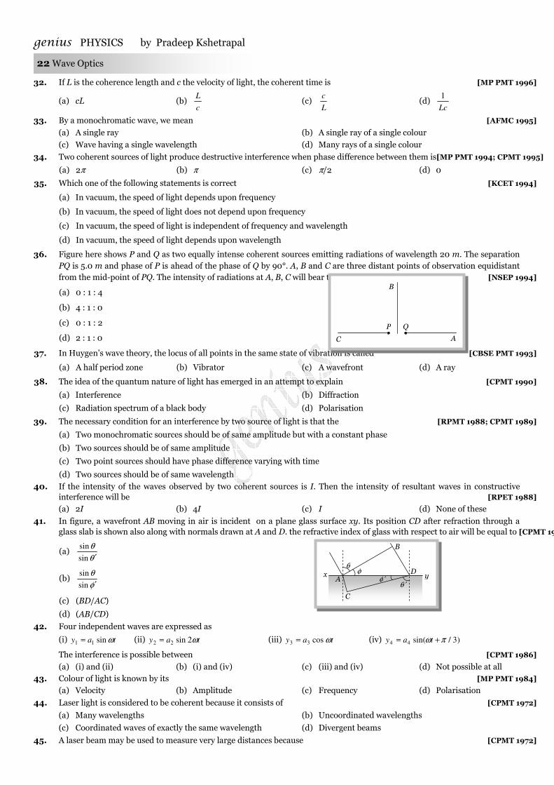
36. Figure here shows P and Q as two equally intense coherent sources emitting radiations of wavelength 20 m. The separation PQ is 5.0 m and phase of P is ahead of the phase of Q by 90°. A, B and C are three distant points of observation equidistant from the mid-point of PQ. The intensity of radiations at A, B, C will bear the ratio [NSEP 1994]
(a) 0 : 1 : 4
(b) 4 : 1 : 0
(c) 0 : 1 : 2
(d) 2 : 1 : 0
37. In Huygen’s wave theory, the locus of all points in the same state of vibration is called [CBSE PMT 1993]
(a) A half period zone (b) Vibrator (c) A wavefront (d) A ray
38. The idea of the quantum nature of light has emerged in an attempt to explain [CPMT 1990]
(a) Interference (b) Diffraction
(c) Radiation spectrum of a black body (d) Polarisation
39. The necessary condition for an interference by two source of light is that the [RPMT 1988; CPMT 1989]
(a) Two monochromatic sources should be of same amplitude but with a constant phase
(b) Two sources should be of same amplitude
(c) Two point sources should have phase difference varying with time
(d) Two sources should be of same wavelength
40. If the intensity of the waves observed by two coherent sources is I. Then the intensity of resultant waves in constructive interference will be [RPET 1988]
(a) 2I (b) 4I (c) I (d) None of these
41. In figure, a wavefront AB moving in air is incident on a plane glass surface xy. Its position CD after refraction through a glass slab is shown also along with normals drawn at A and D. the refractive index of glass with respect to air will be equal to [CPMT 1986, 88]
(a) θθ
′sin
sin
(b) φθ
′sin
sin
(c) (BD/AC)
(d) (AB/CD)
42. Four independent waves are expressed as
(i) tay ωsin11 = (ii) tay ω2sin22 = (iii) tay ωcos33 = (iv) )3/sin(44 πω += tay
The interference is possible between [CPMT 1986]
(a) (i) and (ii) (b) (i) and (iv) (c) (iii) and (iv) (d) Not possible at all 43. Colour of light is known by its [MP PMT 1984]
(a) Velocity (b) Amplitude (c) Frequency (d) Polarisation
44. Laser light is considered to be coherent because it consists of [CPMT 1972]
(a) Many wavelengths (b) Uncoordinated wavelengths
(c) Coordinated waves of exactly the same wavelength (d) Divergent beams
45. A laser beam may be used to measure very large distances because [CPMT 1972]
x A
C
θ′ φ′
φ θ
B
D y
C
P Q
A
B
genius PHYSICS by Pradeep Kshetrapal
Only for students of genius academy Jamanipali, Maxwell classes Korba, and Gupta classes Kusmunda.
Wave Optics 23
(a) It is unidirectional (b) It is coherent (c) It is monochromatic (d) It is not absorbed
46. Interference patterns are not observed in thick films, because
(a) Most of the incident light intensity is observed within the film
(b) A thick film has a high coefficient of reflection
(c) The maxima of interference patterns are far from the minima
(d) There is too much overlapping of colours washing out the interference pattern
47. Phenomenon of interference is not observed by two sodium lamps of same power. It is because both waves have
(a) Not constant phase difference (b) Zero phase difference
(c) Different intensity (d) Different frequencies
48. In a Young’s double slit experiment, the separation between the two slits is 0.9 mm and the fringes are observed one metre away. If it produces the second dark fringe at a distance of 1 mm from the central fringe, the wavelength of monochromatic source of light used is
[KCET 2004]
(a) 500 nm (b) 600 nm (c) 450 nm (d) 400 nm
49. A monochromatic beams of light is used for the formation of fringes on the screen by illuminating the two slits in the Young’s double slit mica is interposed in the path of one of the interfering beams then [AIIMS 2004]
(a) The fringe width increases
(b) The fringe width decreases
(c) The fringe width remains the same but the pattern shifts
(d) The fringe pattern disappears
50. In a Young’s double-slit experiment the fringe width is 0.2 mm. If the wavelength of light used is increased by 10% and the separation between the slits is also increased by 10%, the fringe width will be [MP PMT 2004]
(a) 0.20 mm (b) 0.401 mm (c) 0.242 mm (d) 0.165 mm
51. In Young’s experiment, the distance between the slits is reduced to half and the distance between the slit and screen is doubled, then the fringe width[IIT 1981; MP PMT 1994; RPMT 1997; KCET (Engg./Med.) 2000; UPSEAT 2000; AMU (Engg.) 2000; CPMT 2003]
(a) Will not change (b) Will become half (c) Will be doubled (d) Will become four times
52. In an interference experiment, third bright fringe is obtained at a point on the screen with a light of 700 nm. What should be the wavelength of the light source in order obtain 5th bright fringe at the same point [KCET 2003]
(a) 500 nm (b) 630 nm (c) 750 nm (d) 420 nm
53. In Young’s double-slit experiment the fringe width is β. If entire arrangement is placed in a liquid of refractive index n, the fringe width becomes [KCET 2003]
(a) 1+n
β (b) nβ (c) β / n (d) 1/ −nβ
54. If the separation between slits in Young’s double slit experiment is reduced to rd3
1, the fringe width becomes n times. The
value of n is [MP PET 2003]
(a) 3 (b) 3
1 (c) 9 (d)
9
1
55. When a thin transparent plate of thickness t and refractive index µ is placed in the path of one of the two interfering waves of light, then the path difference changes by [MP PMT 2002]
(a) (µ + 1)t (b) (µ – 1)t (c) t
)1( +µ (d)
t
)1( −µ
56. In a Young’s double slit experiment, the source illuminating the slits is changed from blue to violet. The width of the fringes [Kerala CET (Med.) 2002] (a) Increases (b) Decreases (c) Becomes unequal (d) Remains constant
Young’s double slit experiment
BBaassiicc LLeevveell
genius PHYSICS by Pradeep Kshetrapal 24 Wave Optics
57. In Young’s double slit experiment, the intensity of light coming from the first slit is double the intensity from the second slit. The ratio of the maximum intensity to the minimum intensity on the interference fringe pattern observed is
[KCET (Med.) 2002]
(a) 34 (b) 40 (c) 25 (d) 38
58. In Young’s double slit experiment the wavelength of light was changed from 7000Å to 3500Å. While doubling the separation between the slits which of the following is not true for this experiment [Orissa JEE 2002]
(a) The width of the fringes changes
(b) The colour of bright fringes changes
(c) The separation between successive bright fringes changes
(d) The separation between successive dark fringes remains unchanged
59. In Young’s double slit experiment, the central bright fringe can be identified [KCET (Engg.) 2002]
(a) By using white light instead of monochromatic light (b) As it is narrower than other bright fringes
(c) As it is wider than other bright fringes (d) As it has a greater intensity than the other bright fringes
60. Interference was observed in interference chamber when air was present, now the chamber is evacuated and if the same light is used, a careful observer will see [CBSE PMT 1993; DPMT 2000; BHU 2002]
(a) No interference
(b) Interference with bright bands
(c) Interference with dark bands
(d) Interference in which width of the fringe will be slightly increased
61. A slit of width a is illuminated by white light. For red light )6500( Å=λ . The first minima is obtained at o30=θ . Then the
value of a will be [MP PMT 1987; CPMT 2002]
(a) 3250 Å (b) mm4105.6 −× (c) 1.24 microns (d) cm4106.2 −× 62. In the Young’s double slit experiment with sodium light. The slits are 0.589 m apart. The angular separation of the third
maximum from the central maximum will be (given λ = 589 mm) [Pb. PMT 2002]
(a) )1033.0(sin81 ×− (b) )1033.0(sin
61 −− × (c) )103(sin81 −− × (d) )103(sin
61 −− ×
63. In the Young’s double slit experiment for which colour the fringe width is least [MP PMT 1994; UPSEAT 2001; MP PET 2001] (a) Red (b) Green (c) Blue (d) Yellow
64. In a Young’s double slit experiment, the separation of the two slits is doubled. To keep the same spacing of fringes, the distance D of the screen from the slits should be made [AMU (Engg.) 2001]
(a) 2
D (b)
2
D (c) 2D (d) 4D
65. Consider the following statements Assertion (A): In Young’s experiment, the fringe width for dark fringes is different from that for bright fringes.
Reason (R) : In Young’s double slit experiment performed with a source of white light, only black and bright fringes are observed Of these statements [AIIMS 2001] (a) Both A and R are true and R is a correct explanation of A (b) Both A and R are true but R is not a correct explanation of A (c) Both A and R are false (d) A is false but R is true (e) A is true but R is false
66. In a Young’s double slit experiment, 12 fringes are observed to be formed in a certain segment of the screen when light of wavelength 600 nm is used. If the wavelength of light is changed to 400 nm, number of fringes observed in the same segment of the screen is given by [IIT-JEE (Screening) 2001]
(a) 12 (b) 18 (c) 24 (d) 30
67. In Young’s double slit experiment, a mica slit of thickness t and refractive index µ is introduced in the ray from the first source 1S . By how much distance the fringes pattern will be displaced [RPMT 1996, 97; JIPMER 2000]
(a) tD
d)1( −µ (b) t
d
D)1( −µ (c)
D
d
)1( −µ (d) )1( −µ
d
D
68. Young’s double slit experiment is performed with light of wavelength 550 nm. The separation between the slits is 1.10 mm and screen is placed at distance of 1 m. What is the distance between the consecutive bright or dark fringes [Pb. PMT 2000]
(a) 1.5 mm (b) 1.0 m (c) 0.5 mm (d) None of these
69. In interference obtained by two coherent sources, the fringe width (β) has the following relation with wavelength (λ) [CPMT 1997; MP PMT 2000]
genius PHYSICS by Pradeep Kshetrapal
Only for students of genius academy Jamanipali, Maxwell classes Korba, and Gupta classes Kusmunda.
Wave Optics 25
(a) 2λβ ∝ (b) β ∝ λ (c) β ∝ 1/λ (d) 2−∝ λβ
70. In a double slit experiment, instead of taking slits of equal widths, one slit is made twice as wide as the other. Then in the interference pattern [IIT-JEE (Screening) 2000]
(a) The intensities of both the maxima and the minima increase
(b) The intensity of maxima increases and the minima has zero intensity
(c) The intensity of maxima decreases and that of the minima increases
(d) The intensity of maxima decreases and the minima has zero intensity
71. In Young’s double slit experiment with a source of light of wavelength 6320Å, the first maxima will occur when [Roorkee 1999]
(a) Path difference is 9480 Å (b) Phase difference is 2π radian
(c) Path difference is 6320 Å (d) Phase difference is π radian
72. If a transparent medium of refractive index µ = 1.5 and thickness 5105.2 −×=t m is inserted in front of one of the slits of Young’s double slit experiment, how much will be the shift in the interference pattern? The distance between the slits is 0.5 mm and that between slits and screen is 100 cm [AIIMS 1999]
(a) 5 cm (b) 2.5 cm (c) 0.25 cm (d) 0.1 cm
73. If a torch is used in place of monochromatic light in Young’s experiment what will happens [MH CET (Med.) 1999; KCET (Med.) 1999]
(a) Fringe will appear for a moment then it will disappear (b) Fringes will occur as from monochromatic light
(c) Only bright fringes will appear (d) No fringes will appear
74. When a thin metal plate is placed in the path of one of the interfering beams of light [KCET (Engg./Med.) 1999]
(a) Fringe width increases (b) Fringes disappear (c) Fringes become brighter (d) Fringes become blurred
75. What happens by the use of white light in Young’s double slit experiment [Similar to (AIIMS 2001; Kerala 2000); IIT-JEE 1987; RPMT 1993; MP PMT 1996; RPET 1998; UPSEAT 1999] (a) Bright fringes are obtained (b) Only bright and dark fringes are obtained (c) Central fringe is bright and two or three coloured and dark fringes are observed (d) None of these
76. Young’s experiment is performed in air and then performed in water, the fringe width [CPMT 1990; MP PMT 1994; RPMT 1997]
(a) Will remain same (b) Will decrease (c) Will increase (d) Will be infinite
77. In Young’s experiment, one slit is covered with a blue filter and the other (slit) with a yellow filter. Then the interference pattern
[MP PET 1997]
(a) Will be blue (b) Will be yellow (c) Will be green (d) Will not be formed
78. Two sources give interference pattern which is observed on a screen. D distance apart from the sources. The fringe width is 2w. If the distance D is now doubled, the fringe width will [MP PET 1997]
(a) Become w/2 (b) Remain the same (c) Become w (d) Become 4w
79. In Young’s double slit experiment, angular width of fringes is 0.20° for sodium light of wavelength 5890 Å. If complete system is dipped in water, then angular width of fringes becomes [RPET 1997]
(a) 0.11° (b) 0.15° (c) 0.22° (d) 0.30° 80. In two separate set-ups of the Young’s double slit experiment, fringes of equal width are observed when lights of wavelengths
in the ratio 1 : 2 are used. If the ratio of the slit separation in the two cases is 2 : 1, the ratio of the distances between the plane of the slits and the screen in the two set-ups is [Kurukshetra CEE 1996]
(a) 4 : 1 (b) 1 : 1 (c) 1 : 4 (d) 2 : 1 81. In a Young’s double slit experiment, the central point on the screen is [MP PMT 1996] (a) Bright (b) Dark (c) First bright and then dark (d) First dark and then bright 82. In Young’s double slit experiment, the distance between sources is 1 mm and distance between the screen and source is 1m.
If the fringe width on the screen is 0.06 cm, then λ = [CPMT 1996]
(a) 6000 Å (b) 4000 Å (c) 1200 Å (d) 2400 Å
83. In a Young’s double slit experiment, the distance between two coherent sources is 0.1 mm and the distance between the slits and the screen is 20 cm. If the wavelength of light is 5460 Å then the distance between two consecutive maxima is [RPMT 1995]
(a) 0.5 mm (b) 1.1 mm (c) 1.5 mm (d) 2.2 mm
84. If a thin mica sheet of thickness t and refractive index )3/5(=µ is placed in the path of one of the interfering beams as
shown in figure, then the displacement of the fringe system is [CPMT 1995]
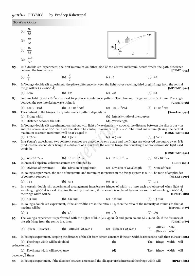
genius PHYSICS by Pradeep Kshetrapal 26 Wave Optics
(a) d
Dt
3
(b) d
Dt
5
(c) d
Dt
4
(d) d
Dt
5
2
85. In a double slit experiment, the first minimum on either side of the central maximum occurs where the path difference between the two paths is [CPMT 1995]
(a) 4
λ (b)
2
λ (c) λ (d) 2λ
86. In Young’s double slit experiment, the phase difference between the light waves reaching third bright fringe from the central fringe will be (λ = 6000 Å) [MP PMT 1994]
(a) Zero (b) 2π (c) 4π (d) 6π
87. Sodium light )106(7 m−×=λ is used to produce interference pattern. The observed fringe width is 0.12 mm. The angle
between the two interfering wave trains is [CPMT 1993]
(a) 1105 −× rad (b) 3105 −× rad (c) 2101 −× rad (d) 3101 −× rad
88. The contrast in the fringes in any interference pattern depends on [Roorkee 1992]
(a) Fringe width (b) Intensity ratio of the sources
(c) Distance between the slits (d) Wavelength
89. In Young’s double slit experiment, carried out with light of wavelength λ = 5000 Å, the distance between the slits is 0.2 mm and the screen is at 200 cm from the slits. The central maximum is at x = 0. The third maximum (taking the central maximum as zeroth maximum) will be at x equal to [CBSE PMT 1992]
(a) 1.67 cm (b) 1.5 cm (c) 0.5 cm (d) 5.0 cm
90. In a Young’s experiment, two coherent sources are placed 0.90 mm apart and the fringes are observed one metre away. If it produces the second dark fringe at a distance of 1 mm from the central fringe, the wavelength of monochromatic light used would be
[CBSE PMT 1992]
(a) cm41060 −× (b) cm41010 −× (c) cm51010 −× (d) cm51060 −×
91. In Fresnel’s biprism, coherent sources are obtained by [RPET 1991]
(a) Division of wavefront (b) Division of amplitude (c) Division of wavelength (d) None of these
92. In Young’s experiment, the ratio of maximum and minimum intensities in the fringe system is 9 : 1. The ratio of amplitudes of coherent sources is [NCERT 1990]
(a) 9 : 1 (b) 3 : 1 (c) 2 : 1 (d) 1 : 1
93. In a certain double slit experimental arrangement interference fringes of width 1.0 mm each are observed when light of wavelength 5000 Å is used. Keeping the set up unaltered, if the source is replaced by another source of wavelength 6000 Å, the fringe width will be [CPMT 1988]
(a) 0.5 mm (b) 1.0 mm (c) 1.2 mm (d) 1.5 mm
94. In Young’s double slit experiment, if the slit widths are in the ratio 1 : 9, then the ratio of the intensity at minima to that at maxima will be [MP PET 1987]
(a) 1 (b) 1/9 (c) 1/4 (d) 1/3
95. The Young’s experiment is performed with the lights of blue (λ = 4360 Å) and green colour (λ = 5460 Å). If the distance of the 4th fringe from the centre is x, then [CPMT 1987]
(a) )Green()Blue( xx = (b) )Green()Blue( xx > (c) )Green()Blue( xx < (d) 4360
5460
)Green(
)Blue(=
x
x
96. In Young’s experiment, keeping the distance of the slit from screen constant if the slit width is reduced to half, then [CPMT 1986]
(a) The fringe width will be doubled (b) The fringe width will reduce to half
(c) The fringe width will not change (d) The fringe width will
become 2 times
97. In Young’s experiment, if the distance between screen and the slit aperture is increased the fringe width will [RPET 1986]
D S2
S1
2d
t P
genius PHYSICS by Pradeep Kshetrapal
Only for students of genius academy Jamanipali, Maxwell classes Korba, and Gupta classes Kusmunda.
Wave Optics 27
(a) Decrease (b) Increases but intensity will decrease
(c) Increase but intensity remains unchanged (d) Remains unchanged but intensity decreases
98. In Fresnel’s biprism experiment, the two coherent sources are [RPET 1985]
(a) Real (b) Imaginary
(c) One is real and the other is imaginary (d) None of these
99. In Fresnel’s experiment, the width of the fringe depends upon the distance [RPET 1985]
(a) Between the prism and the slit aperture
(b) Of the prism from the screen
(c) Of screen from the imaginary light sources
(d) Of the screen from the prism and the distance from the imaginary sources
100. In the Young’s double slit experiment, the ratio of intensities of bright and dark fringes is 9. This means that [IIT-JEE 1982] (a) The intensities of individual sources are 5 and 4 units respectively (b) The intensities of individual sources are 4 and 1 units respectively (c) The ratio of their amplitudes is 3
(d) The ratio of their amplitudes is 2
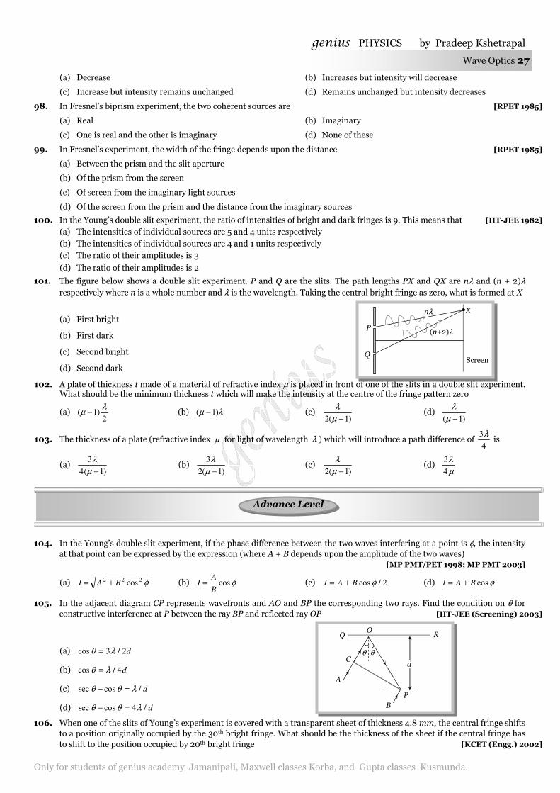
101. The figure below shows a double slit experiment. P and Q are the slits. The path lengths PX and QX are nλ and (n + 2)λ respectively where n is a whole number and λ is the wavelength. Taking the central bright fringe as zero, what is formed at X
(a) First bright
(b) First dark
(c) Second bright
(d) Second dark
102. A plate of thickness t made of a material of refractive index µ is placed in front of one of the slits in a double slit experiment. What should be the minimum thickness t which will make the intensity at the centre of the fringe pattern zero
(a) 2
)1(λ
µ − (b) λµ )1( − (c) )1(2 −µ
λ (d)
)1( −µλ
103. The thickness of a plate (refractive index µ for light of wavelength λ ) which will introduce a path difference of 4
3λ is
(a) )1(4
3
−µλ
(b) )1(2
3
−µλ
(c) )1(2 −µ
λ (d)
µλ
4
3
104. In the Young’s double slit experiment, if the phase difference between the two waves interfering at a point is φ, the intensity at that point can be expressed by the expression (where A + B depends upon the amplitude of the two waves)
[MP PMT/PET 1998; MP PMT 2003]
(a) φ222 cosBAI += (b) φcosB
AI = (c) 2/cos φBAI += (d) φcosBAI +=
105. In the adjacent diagram CP represents wavefronts and AO and BP the corresponding two rays. Find the condition on θ for constructive interference at P between the ray BP and reflected ray OP [IIT-JEE (Screening) 2003]
(a) d2/3cos λθ =
(b) d4/cos λθ =
(c) d/cossec λθθ =−
(d) d/4cossec λθθ =−
106. When one of the slits of Young’s experiment is covered with a transparent sheet of thickness 4.8 mm, the central fringe shifts to a position originally occupied by the 30th bright fringe. What should be the thickness of the sheet if the central fringe has to shift to the position occupied by 20th bright fringe [KCET (Engg.) 2002]
Q
P
nλ
(n+2)λ
X
Screen
d
P B
R
θ
A
C θ
O Q
AAddvvaannccee LLeevveell
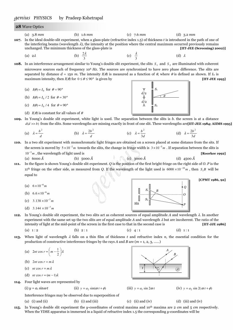
genius PHYSICS by Pradeep Kshetrapal 28 Wave Optics
(a) 3.8 mm (b) 1.6 mm (c) 7.6 mm (d) 3.2 mm
107. In the ideal double-slit experiment, when a glass-plate (refractive index 1.5) of thickness t is introduced in the path of one of the interfering beams (wavelength λ), the intensity at the position where the central maximum occurred previously remains unchanged. The minimum thickness of the glass-plate is [IIT-JEE (Screening) 2002)]
(a) 2λ (b) 3
2λ (c)
3
λ (d) λ
108. In an interference arrangement similar to Young’s double slit experiment, the slits 1S and 2S are illuminated with coherent
microwave sources each of frequency 106 Hz. The sources are synchronized to have zero phase difference. The slits are separated by distance d = 150 m. The intensity I(θ) is measured as a function of θ, where θ is defined as shown. If I0 is maximum intensity, then I(θ) for °≤≤ 900 θ is given by [IIT-JEE 1995]
(a) 0)( II =θ for °= 90θ
(b) 2/)( 0II =θ for °= 30θ
(c) 4/)( 0II =θ for °= 90θ
(d) I(θ) is constant for all values of θ
109. In Young’s double slit experiment, white light is used. The separation between the slits is b. the screen is at a distance )( bdd >> from the slits. Some wavelengths are missing exactly in front of one slit. These wavelengths are[IIT-JEE 1984; AIIMS 1995]
(a) d
b 2
=λ (b) d
b 22
=λ (c) d
b
3
2
=λ (d) d
b
3
22
=λ
110. In a two slit experiment with monochromatic light fringes are obtained on a screen placed at some distance from the sits. If
the screen is moved by m2105 −× towards the slits, the change in fringe width is m5103 −× . If separation between the slits is
m310 − , the wavelength of light used is [Roorkee 1992]
(a) 6000 Å (b) 5000 Å (c) 3000 Å (d) 4500 Å
111. In the figure is shown Young’s double slit experiment. Q is the position of the first bright fringe on the right side of O. P is the
11th fringe on the other side, as measured from Q. If the wavelength of the light used is m10106000 −× , then BS1 will be
equal to [CPMT 1986, 92]
(a) m6106 −×
(b) m6106.6 −×
(c) m710138.3 −×
(d) m710144.3 −×
112. In Young’s double slit experiment, the two slits act as coherent sources of equal amplitude A and wavelength λ. In another experiment with the same set up the two slits are of equal amplitude A and wavelength λ but are incoherent. The ratio of the intensity of light at the mid-point of the screen in the first case to that in the second case is [IIT-JJE 1986]
(a) 1 : 2 (b) 2 : 1 (c) 4 : 1 (d) 1 : 1
113. When light of wavelength λ falls on a thin film of thickness t and refractive index n, the essential condition for the production of constructive interference fringes by the rays A and B are (m = 1, 2, 3, ……)
(a) λ
−=
2
1cos2 mrnt
(b) λmrnt =cos2
(c) λmrnt =cos
(d) λ)1(cos −= mrnt
114. Four light waves are represented by
(i) y = a1 sinω t (ii) )sin(2 φω += tay (iii) tay ω2sin1= (iv) )(2sin2 φω += tay
Interference fringes may be observed due to superposition of
(a) (i) and (ii) (b) (i) and (iii) (c) (ii) and (iv) (d) (iii) and (iv)
115. In Young's double slit experiment the y-coordinates of central maxima and 10th maxima are 2 cm and 5 cm respectively. When the YDSE apparatus is immersed in a liquid of refractive index 1.5 the corresponding y-coordinates will be
d/2 S1
S2
θ
d/2
A B
t r µ
S1
S2
O
Q
P Slit
B
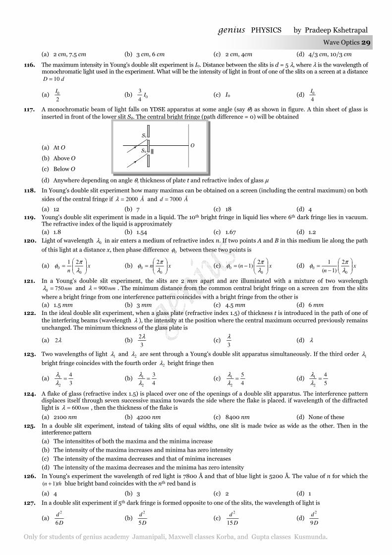
genius PHYSICS by Pradeep Kshetrapal
Only for students of genius academy Jamanipali, Maxwell classes Korba, and Gupta classes Kusmunda.
Wave Optics 29
(a) 2 cm, 7.5 cm (b) 3 cm, 6 cm (c) 2 cm, 4cm (d) 4/3 cm, 10/3 cm
116. The maximum intensity in Young's double slit experiment is I0. Distance between the slits is d = 5 λ, where λ is the wavelength of monochromatic light used in the experiment. What will be the intensity of light in front of one of the slits on a screen at a distance
dD 10=
(a) 2
0I (b) 04
3I (c) I0 (d)
4
0I
117. A monochromatic beam of light falls on YDSE apparatus at some angle (say θ) as shown in figure. A thin sheet of glass is inserted in front of the lower slit S2. The central bright fringe (path difference = 0) will be obtained
(a) At O
(b) Above O
(c) Below O
(d) Anywhere depending on angle θ, thickness of plate t and refractive index of glass µ
118. In Young's double slit experiment how many maximas can be obtained on a screen (including the central maximum) on both
sides of the central fringe if Å2000=λ and Åd 7000=
(a) 12 (b) 7 (c) 18 (d) 4 119. Young's double slit experiment is made in a liquid. The 10th bright fringe in liquid lies where 6th dark fringe lies in vacuum.
The refractive index of the liquid is approximately (a) 1.8 (b) 1.54 (c) 1.67 (d) 1.2
120. Light of wavelength 0λ in air enters a medium of refractive index n. If two points A and B in this medium lie along the path
of this light at a distance x, then phase difference 0φ between these two points is
(a) xn
=
0
0
21
λπ
φ (b) xn
=
0
0
2
λπ
φ (c) xn
−=
0
0
2)1(
λπ
φ (d) xn
−=
0
0
2
)1(
1
λπ
φ
121. In a Young's double slit experiment, the slits are 2 mm apart and are illuminated with a mixture of two wavelength nm7500 =λ and nm900=λ . The minimum distance from the common central bright fringe on a screen 2m from the slits
where a bright fringe from one interference pattern coincides with a bright fringe from the other is (a) 1.5 mm (b) 3 mm (c) 4.5 mm (d) 6 mm
122. In the ideal double slit experiment, when a glass plate (refractive index 1.5) of thickness t is introduced in the path of one of the interfering beams (wavelength λ ), the intensity at the position where the central maximum occurred previously remains unchanged. The minimum thickness of the glass plate is
(a) λ2 (b) 3
2λ (c)
3
λ (d) λ
123. Two wavelengths of light 1λ and 2λ are sent through a Young's double slit apparatus simultaneously. If the third order 1λ
bright fringe coincides with the fourth order 2λ bright fringe then
(a) 3
4
2
1 =λλ
(b) 4
3
2
1 =λλ
(c) 4
5
2
1 =λλ
(d) 5
4
2
1 =λλ
124. A flake of glass (refractive index 1.5) is placed over one of the openings of a double slit apparatus. The interference pattern displaces itself through seven successive maxima towards the side where the flake is placed. if wavelength of the diffracted light is nm600=λ , then the thickness of the flake is
(a) 2100 nm (b) 4200 nm (c) 8400 nm (d) None of these
125. In a double slit experiment, instead of taking slits of equal widths, one slit is made twice as wide as the other. Then in the interference pattern
(a) The intensitites of both the maxima and the minima increase
(b) The intensity of the maxima increases and minima has zero intensity
(c) The intensity of the maxima decreases and that of minima increases
(d) The intensity of the maxima decreases and the minima has zero intensity
126. In Young's experiment the wavelength of red light is 7800 Å and that of blue light is 5200 Å. The value of n for which the thn )1( + blue bright band coincides with the nth red band is
(a) 4 (b) 3 (c) 2 (d) 1
127. In a double slit experiment if 5th dark fringe is formed opposite to one of the slits, the wavelength of light is
(a) D
d
6
2
(b) D
d
5
2
(c) D
d
15
2
(d) D
d
9
2
S2
S1
O
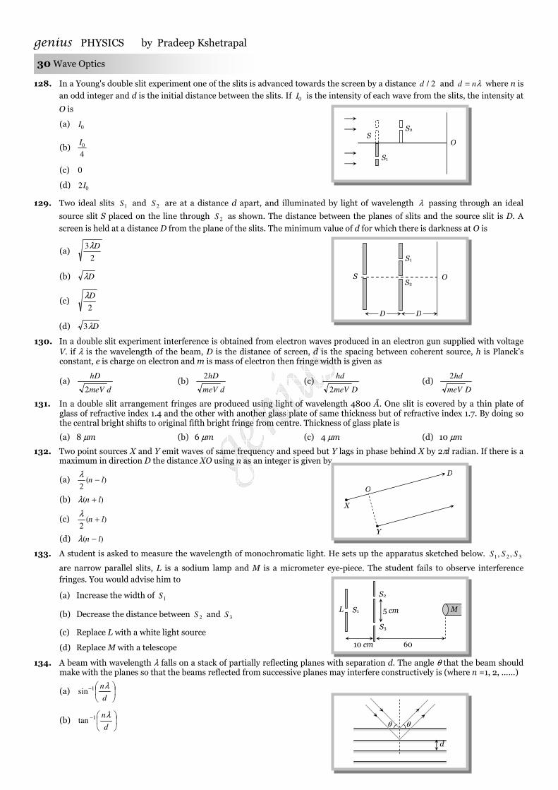
genius PHYSICS by Pradeep Kshetrapal 30 Wave Optics
128. In a Young's double slit experiment one of the slits is advanced towards the screen by a distance 2/d and λnd = where n is
an odd integer and d is the initial distance between the slits. If 0I is the intensity of each wave from the slits, the intensity at
O is
(a) 0I
(b) 4
0I
(c) 0
(d) 02I
129. Two ideal slits 1S and 2S are at a distance d apart, and illuminated by light of wavelength λ passing through an ideal
source slit S placed on the line through 2S as shown. The distance between the planes of slits and the source slit is D. A
screen is held at a distance D from the plane of the slits. The minimum value of d for which there is darkness at O is
(a) 2
3 Dλ
(b) Dλ
(c) 2
Dλ
(d) Dλ3
130. In a double slit experiment interference is obtained from electron waves produced in an electron gun supplied with voltage V. if λ is the wavelength of the beam, D is the distance of screen, d is the spacing between coherent source, h is Planck’s constant, e is charge on electron and m is mass of electron then fringe width is given as
(a) dmeV
hD
2 (b)
dmeV
hD2 (c)
DmeV
hd
2 (d)
DmeV
hd2
131. In a double slit arrangement fringes are produced using light of wavelength 4800 Å. One slit is covered by a thin plate of glass of refractive index 1.4 and the other with another glass plate of same thickness but of refractive index 1.7. By doing so the central bright shifts to original fifth bright fringe from centre. Thickness of glass plate is
(a) 8 µm (b) 6 µm (c) 4 µm (d) 10 µm
132. Two point sources X and Y emit waves of same frequency and speed but Y lags in phase behind X by 2πl radian. If there is a maximum in direction D the distance XO using n as an integer is given by
(a) )(2
ln −λ
(b) )( ln +λ
(c) )(2
ln +λ
(d) )( ln −λ
133. A student is asked to measure the wavelength of monochromatic light. He sets up the apparatus sketched below. 321 ,, SSS
are narrow parallel slits, L is a sodium lamp and M is a micrometer eye-piece. The student fails to observe interference fringes. You would advise him to
(a) Increase the width of 1S
(b) Decrease the distance between 2S and 3S
(c) Replace L with a white light source
(d) Replace M with a telescope
134. A beam with wavelength λ falls on a stack of partially reflecting planes with separation d. The angle θ that the beam should make with the planes so that the beams reflected from successive planes may interfere constructively is (where n =1, 2, ……)
(a)
−
d
nλ1sin
(b)
−
d
nλ1tan
O
X
Y
D
S2
S1
S O
D D
S1
S2 S
O
θ θ
d
S1
S2
S3
5 cm
10 cm 60 cm
M L
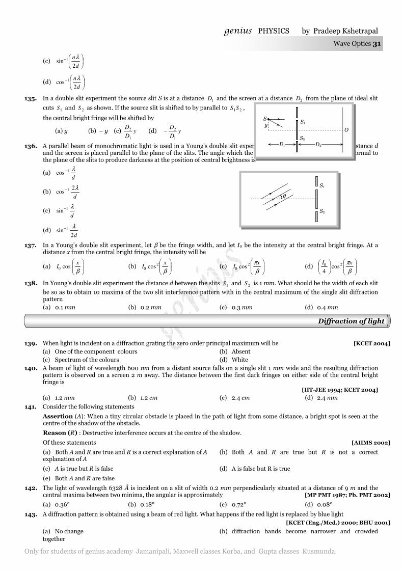
genius PHYSICS by Pradeep Kshetrapal
Only for students of genius academy Jamanipali, Maxwell classes Korba, and Gupta classes Kusmunda.
Wave Optics 31
(c)
−
d
n
2sin 1 λ
(d)
−
d
n
2cos 1 λ
135. In a double slit experiment the source slit S is at a distance 1D and the screen at a distance 2D from the plane of ideal slit
cuts 1S and 2S as shown. If the source slit is shifted to by parallel to 21SS ,
the central bright fringe will be shifted by
(a) y (b) – y (c) yD
D
1
2 (d) yD
D
1
2−
136. A parallel beam of monochromatic light is used in a Young’s double slit experiment. The slits are separated by a distance d and the screen is placed parallel to the plane of the slits. The angle which the incident beam must make with the normal to the plane of the slits to produce darkness at the position of central brightness is
(a) d
λ1cos
−
(b) d
λ2cos
1−
(c) d
λ1sin
−
(d) d2
sin1 λ−
137. In a Young’s double slit experiment, let β be the fringe width, and let I0 be the intensity at the central bright fringe. At a distance x from the central bright fringe, the intensity will be
(a)
βx
I cos0 (b)
βx
I 20 cos (c)
βπx
I 20 cos (d)
βπxI 20 cos
4
138. In Young’s double slit experiment the distance d between the slits 1S and 2S is 1 mm. What should be the width of each slit
be so as to obtain 10 maxima of the two slit interference pattern with in the central maximum of the single slit diffraction pattern
(a) 0.1 mm (b) 0.2 mm (c) 0.3 mm (d) 0.4 mm
139. When light is incident on a diffraction grating the zero order principal maximum will be [KCET 2004] (a) One of the component colours (b) Absent (c) Spectrum of the colours (d) White
140. A beam of light of wavelength 600 nm from a distant source falls on a single slit 1 mm wide and the resulting diffraction pattern is observed on a screen 2 m away. The distance between the first dark fringes on either side of the central bright fringe is
[IIT-JEE 1994; KCET 2004] (a) 1.2 mm (b) 1.2 cm (c) 2.4 cm (d) 2.4 mm
141. Consider the following statements
Assertion (A): When a tiny circular obstacle is placed in the path of light from some distance, a bright spot is seen at the centre of the shadow of the obstacle.
Reason (R) : Destructive interference occurs at the centre of the shadow.
Of these statements [AIIMS 2002]
(a) Both A and R are true and R is a correct explanation of A (b) Both A and R are true but R is not a correct explanation of A
(c) A is true but R is false (d) A is false but R is true
(e) Both A and R are false
142. The light of wavelength 6328 Å is incident on a slit of width 0.2 mm perpendicularly situated at a distance of 9 m and the central maxima between two minima, the angular is approximately [MP PMT 1987; Pb. PMT 2002]
(a) 0.36° (b) 0.18° (c) 0.72° (d) 0.08°
143. A diffraction pattern is obtained using a beam of red light. What happens if the red light is replaced by blue light [KCET (Eng./Med.) 2000; BHU 2001]
(a) No change (b) diffraction bands become narrower and crowded together
S y
S1
S2
D2 D1
O
θ
S1
S2
Diffraction of light
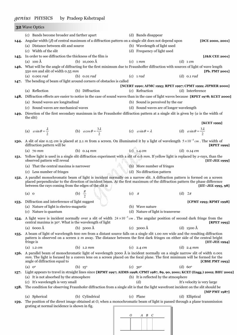
genius PHYSICS by Pradeep Kshetrapal 32 Wave Optics
(c) Bands become broader and farther apart (d) Bands disappear
144. Angular width (β) of central maximum of a diffraction pattern on a single slit does not depend upon [DCE 2000, 2001]
(a) Distance between slit and source (b) Wavelength of light used
(c) Width of the slit (d) Frequency of light used
145. In order to see diffraction the thickness of the film is [J&K CEE 2001]
(a) 100 Å (b) 10,000 Å (c) 1 mm (d) 1 cm
146. What will be the angle of diffracting for the first minimum due to Fraunhoffer diffraction with sources of light of wave length 550 nm and slit of width 0.55 mm [Pb. PMT 2001] (a) 0.001 rad (b) 0.01 rad (c) 1 rad (d) 0.1 rad
147. The bending of beam of light around corners of obstacles is called [NCERT 1990; AFMC 1995; RPET 1997; CPMT 1999; JIPMER 2000]
(a) Reflection (b) Diffraction (c) Refraction (d) Interference
148. Diffraction effects are easier to notice in the case of sound waves than in the case of light waves because [RPET 1978; KCET 2000]
(a) Sound waves are longitudinal (b) Sound is perceived by the ear
(c) Sound waves are mechanical waves (d) Sound waves are of longer wavelength
149. Direction of the first secondary maximum in the Fraunhofer diffraction pattern at a single slit is given by (a is the width of the slit)
[KCET 1999]
(a) 2
sinλ
θ =a (b) 2
3cos
λθ =a (c) λθ =sina (d)
2
3sin
λθ =a
150. A slit of size 0.15 cm is placed at 2.1 m from a screen. On illuminated it by a light of wavelength cm5105 −× . The width of diffraction pattern will be [RPET 1999]
(a) 70 mm (b) 0.14 mm (c) 1.4 cm (d) 0.14 cm
151. Yellow light is used in a single slit diffraction experiment with a slit of 0.6 mm. If yellow light is replaced by x-rays, than the observed pattern will reveal [IIT-JEE 1999]
(a) That the central maxima is narrower (b) More number of fringes
(c) Less number of fringes (d) No diffraction pattern
152. A parallel monochromatic beam of light is incident normally on a narrow slit. A diffraction pattern is formed on a screen placed perpendicular to the direction of incident beam. At the first maximum of the diffraction pattern the phase difference between the rays coming from the edges of the slit is [IIT–JEE 1995, 98]
(a) 0 (b) 2
π (c) π (d) π2
153. Diffraction and interference of light suggest [CPMT 1995; RPMT 1998] (a) Nature of light is electro-magnetic (b) Wave nature (c) Nature is quantum (d) Nature of light is transverse
154. A light wave is incident normally over a slit of width cm51024 −× . The angular position of second dark fringe from the central maxima is 30o. What is the wavelength of light [RPET 1995]
(a) 6000 Å (b) 5000 Å (c) 3000 Å (d) 1500 Å
155. A beam of light of wavelength 600 nm from a distant source falls on a single slit 1.00 nm wide and the resulting diffraction pattern is observed on a screen 2 m away. The distance between the first dark fringes on either side of the central bright fringe is [IIT-JEE 1994]
(a) 1.2 cm (b) 1.2 mm (c) 2.4 cm (d) 2.4 mm
156. A parallel beam of monochromatic light of wavelength 5000 Å is incident normally on a single narrow slit of width 0.001 mm. The light is focused by a convex lens on a screen placed on the focal plane. The first minimum will be formed for the angle of diffraction equal to [CBSE PMT 1993]
(a) 0o (b) 15o (c) 30o (d) 60o
157. Light appears to travel in straight lines since [RPMT 1997; AIIMS 1998; CPMT 1987, 89, 90, 2001; KCET (Engg.) 2002; BHU 2002] (a) It is not absorbed by the atmosphere (b) It is reflected by the atmosphere (c) It's wavelength is very small (d) It's velocity is very large
158. The condition for observing Fraunhofer diffraction from a single slit is that the light wavefront incident on the slit should be [MP PMT 1987]
(a) Spherical (b) Cylindrical (c) Plane (d) Elliptical 159. The position of the direct image obtained at O, when a monochromatic beam of light is passed through a plane transmission
grating at normal incidence is shown in fig.
O A B C
genius PHYSICS by Pradeep Kshetrapal
Only for students of genius academy Jamanipali, Maxwell classes Korba, and Gupta classes Kusmunda.
Wave Optics 33
The diffracted images A, B and C correspond to the first, second and third order diffraction when the source is replaced by an another source of shorter wavelength [CPMT 1986] (a) All the four shift in the direction C to O (b) All the four will shift in the direction O to C (c) The images C, B and A will shift toward O (d) The images C, B and A will shift away from O
160. To observe diffraction the size of an obstacle [CPMT 1982] (a) Should be of the same order as wavelength (b) Should be much larger than the wavelength
(c) Have no relation to wavelength (d) Should be exactly 2
λ
161. The first diffraction minima due to a single slit diffraction is at o30=θ for a light of wavelength 5000 Å. The width of the slit is
[CPMT 1985]
(a) cm5105 −× (b) cm4100.1 −× (c) cm5105.2 −× (d) cm51025.1 −× 162. Radio waves diffract pronoucedly around buildings while light waves which are also electromagnetic waves do not because [PPE 1978]
(a) Wavelength of the radio waves is not comparable with the size of the obstacle (b) Wavelength of radio waves is of the order of 200-500 m hence they bend more than the light waves whose wavelength is
very small (c) Light waves are transverse whereas radio waves are longitudinal (d) None of the above
163. One cannot obtain diffraction from a wide slit illuminated by a monochromatic light because [PPE 1978]
(a) The half period elements contained in a wide slit are very large so the resultant effect is general illumination
(b) The half period elements contained in a wide slit are small so the resultant effect is general illumination
(c) Diffraction patterns are superimposed by interference pattern and hence the result is general illumination
(d) None of these
164. In the far field diffraction pattern of a single slit under polychromatic illumination, the first minimum with the wavelength
1λ is found to be coincident with the third maximum at 2λ . So
(a) 21 3.03 λλ = (b) 213 λλ = (c) 21 5.3 λλ = (d) 21 33.0 λλ =
165. In case of Fresnel diffraction (a) Both source and screen are at finite distance from diffracting device (b) Source is at finite distance while screen at infinity from diffraction device (c) Screen is at finite distance while source at infinity from diffracting device (d) Both source and screen are effectively at infinity from diffracting device
166. Light of wavelength λ = 5000 Å falls normally on a narrow slit. A screen placed at a distance of 1 m from the slit and perpendicular to the direction of light. The first minima of the diffraction pattern is situated at 5 mm from the centre of central maximum. The width of the slit is (a) 0.1 mm (b) 1.0 mm (c) 0.5 mm (d) 0.2 mm
167. Light falls normally on a slit of width 0.3 mm. A lens of focal length 40 cm collects the rays at its focal plane. The distance of the first dark band from the direct one is 0.8 mm. The wavelength of light is
(a) 4800 Å (b) 5000 Å (c) 6000 Å (d) 5896 Å
168. A parallel monochromatic beam of light is incident at an angle θ to the normal of a slit of width e. The central point O of the screen will be dark if
(a) λθ ne =sin where n = 1, 3, 5 ...
(b) λθ ne =sin where n = 1, 2, 3 ...
(c) 2/)12(sin λθ −= ne where n = 1, 2, 3 ......
(d) λθ ne =cos where n = 1, 2, 3, 4 ........
169. The angle of incidence at which reflected light is totally polarized for reflection from air to glass (refraction index n) is [AIEEE 2004]
(a) )(sin1 n− (b)
−
n
1sin 1 (c)
−
n
1tan 1 (d) )(tan
1 n−
S2
S1
O θ
Polarization of Light
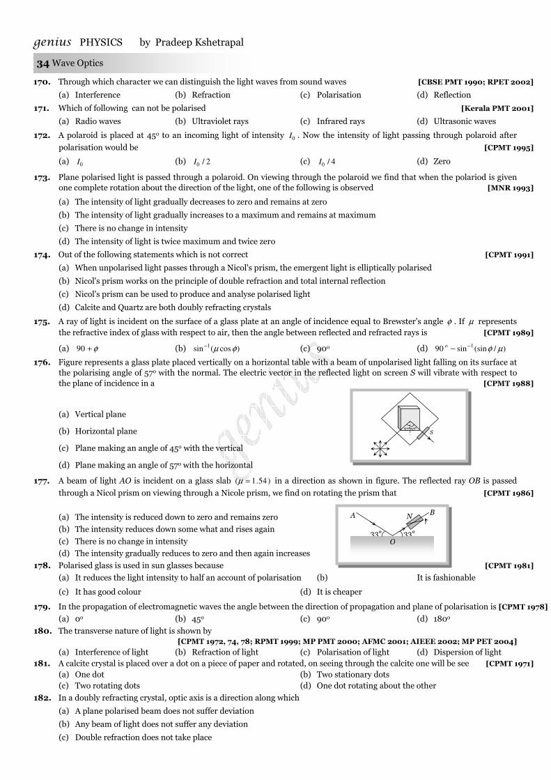
genius PHYSICS by Pradeep Kshetrapal 34 Wave Optics
170. Through which character we can distinguish the light waves from sound waves [CBSE PMT 1990; RPET 2002]
(a) Interference (b) Refraction (c) Polarisation (d) Reflection
171. Which of following can not be polarised [Kerala PMT 2001]
(a) Radio waves (b) Ultraviolet rays (c) Infrared rays (d) Ultrasonic waves
172. A polaroid is placed at 45o to an incoming light of intensity 0I . Now the intensity of light passing through polaroid after
polarisation would be [CPMT 1995]
(a) 0I (b) 2/0I (c) 4/0I (d) Zero
173. Plane polarised light is passed through a polaroid. On viewing through the polaroid we find that when the polariod is given one complete rotation about the direction of the light, one of the following is observed [MNR 1993]
(a) The intensity of light gradually decreases to zero and remains at zero
(b) The intensity of light gradually increases to a maximum and remains at maximum
(c) There is no change in intensity
(d) The intensity of light is twice maximum and twice zero
174. Out of the following statements which is not correct [CPMT 1991]
(a) When unpolarised light passes through a Nicol's prism, the emergent light is elliptically polarised
(b) Nicol's prism works on the principle of double refraction and total internal reflection
(c) Nicol's prism can be used to produce and analyse polarised light
(d) Calcite and Quartz are both doubly refracting crystals
175. A ray of light is incident on the surface of a glass plate at an angle of incidence equal to Brewster's angle φ . If µ represents the refractive index of glass with respect to air, then the angle between reflected and refracted rays is [CPMT 1989]
(a) φ+90 (b) )cos(sin1 φµ− (c) 90o (d) )/(sinsin90
1 µφ−−o
176. Figure represents a glass plate placed vertically on a horizontal table with a beam of unpolarised light falling on its surface at the polarising angle of 57o with the normal. The electric vector in the reflected light on screen S will vibrate with respect to the plane of incidence in a [CPMT 1988]
(a) Vertical plane
(b) Horizontal plane
(c) Plane making an angle of 45o with the vertical
(d) Plane making an angle of 57o with the horizontal
177. A beam of light AO is incident on a glass slab )54.1( =µ in a direction as shown in figure. The reflected ray OB is passed
through a Nicol prism on viewing through a Nicole prism, we find on rotating the prism that [CPMT 1986]
(a) The intensity is reduced down to zero and remains zero
(b) The intensity reduces down some what and rises again
(c) There is no change in intensity
(d) The intensity gradually reduces to zero and then again increases
178. Polarised glass is used in sun glasses because [CPMT 1981]
(a) It reduces the light intensity to half an account of polarisation (b) It is fashionable
(c) It has good colour (d) It is cheaper
179. In the propagation of electromagnetic waves the angle between the direction of propagation and plane of polarisation is [CPMT 1978]
(a) 0o (b) 45o (c) 90o (d) 180o
180. The transverse nature of light is shown by [CPMT 1972, 74, 78; RPMT 1999; MP PMT 2000; AFMC 2001; AIEEE 2002; MP PET 2004]
(a) Interference of light (b) Refraction of light (c) Polarisation of light (d) Dispersion of light 181. A calcite crystal is placed over a dot on a piece of paper and rotated, on seeing through the calcite one will be see [CPMT 1971]
(a) One dot (b) Two stationary dots (c) Two rotating dots (d) One dot rotating about the other
182. In a doubly refracting crystal, optic axis is a direction along which
(a) A plane polarised beam does not suffer deviation
(b) Any beam of light does not suffer any deviation
(c) Double refraction does not take place
57° 57° S
A N B
33°33°O
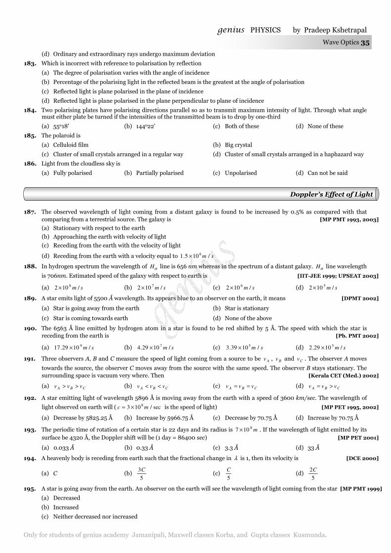
genius PHYSICS by Pradeep Kshetrapal
Only for students of genius academy Jamanipali, Maxwell classes Korba, and Gupta classes Kusmunda.
Wave Optics 35
(d) Ordinary and extraordinary rays undergo maximum deviation
183. Which is incorrect with reference to polarisation by reflection
(a) The degree of polarisation varies with the angle of incidence
(b) Percentage of the polarising light in the reflected beam is the greatest at the angle of polarisation
(c) Reflected light is plane polarised in the plane of incidence
(d) Reflected light is plane polarised in the plane perpendicular to plane of incidence
184. Two polarising plates have polarising directions parallel so as to transmit maximum intensity of light. Through what angle must either plate be turned if the intensities of the transmitted beam is to drop by one-third
(a) 55o18' (b) 144o22' (c) Both of these (d) None of these
185. The polaroid is
(a) Celluloid film (b) Big crystal
(c) Cluster of small crystals arranged in a regular way (d) Cluster of small crystals arranged in a haphazard way
186. Light from the cloudless sky is
(a) Fully polarised (b) Partially polarised (c) Unpolarised (d) Can not be said
187. The observed wavelength of light coming from a distant galaxy is found to be increased by 0.5% as compared with that comparing from a terrestrial source. The galaxy is [MP PMT 1993, 2003]
(a) Stationary with respect to the earth
(b) Approaching the earth with velocity of light
(c) Receding from the earth with the velocity of light
(d) Receding from the earth with a velocity equal to sm /105.1 6×
188. In hydrogen spectrum the wavelength of αH line is 656 nm whereas in the spectrum of a distant galaxy. αH line wavelength
is 706nm. Estimated speed of the galaxy with respect to earth is [IIT-JEE 1999; UPSEAT 2003]
(a) sm /102 8× (b) sm /102 7× (c) sm /102 6× (d) sm /102 5×
189. A star emits light of 5500 Å wavelength. Its appears blue to an observer on the earth, it means [DPMT 2002]
(a) Star is going away from the earth (b) Star is stationary
(c) Star is coming towards earth (d) None of the above
190. The 6563 Å line emitted by hydrogen atom in a star is found to be red shifted by 5 Å. The speed with which the star is receding from the earth is [Pb. PMT 2002]
(a) sm /1029.17 9× (b) sm /1029.4 7× (c) sm /1039.3 5× (d) sm /1029.2 5×
191. Three observers A, B and C measure the speed of light coming from a source to be Av , Bv and Cv . The observer A moves
towards the source, the observer C moves away from the source with the same speed. The observer B stays stationary. The surrounding space is vacuum very where. Then [Kerala CET (Med.) 2002]
(a) CBA vvv >> (b) CBA vvv << (c) CBA vvv == (d) CBA vvv >=
192. A star emitting light of wavelength 5896 Å is moving away from the earth with a speed of 3600 km/sec. The wavelength of
light observed on earth will ( sec/103 8 mc ×= is the speed of light) [MP PET 1995, 2002]
(a) Decrease by 5825.25 Å (b) Increase by 5966.75 Å (c) Decrease by 70.75 Å (d) Increase by 70.75 Å
193. The periodic time of rotation of a certain star is 22 days and its radius is m8107 × . If the wavelength of light emitted by its surface be 4320 Å, the Doppler shift will be (1 day = 86400 sec) [MP PET 2001]
(a) 0.033 Å (b) 0.33 Å (c) 3.3 Å (d) 33 Å
194. A heavenly body is receding from earth such that the fractional change in λ is 1, then its velocity is [DCE 2000]
(a) C (b) 5
3C (c)
5
C (d)
5
2C
195. A star is going away from the earth. An observer on the earth will see the wavelength of light coming from the star [MP PMT 1999]
(a) Decreased
(b) Increased
(c) Neither decreased nor increased
Doppler's Effect of Light
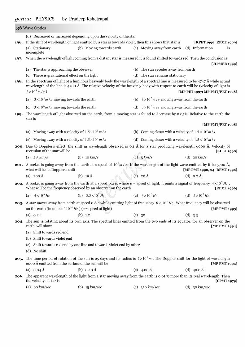
genius PHYSICS by Pradeep Kshetrapal 36 Wave Optics
(d) Decreased or increased depending upon the velocity of the star
196. If the shift of wavelength of light emitted by a star is towards violet, then this shows that star is [RPET 1996; RPMT 1999]
(a) Stationary (b) Moving towards earth (c) Moving away from earth (d) Information is incomplete
197. When the wavelength of light coming from a distant star is measured it is found shifted towards red. Then the conclusion is
[JIPMER 1999]
(a) The star is approaching the observer (b) The star recedes away from earth
(c) There is gravitational effect on the light (d) The star remains stationary
198. In the spectrum of light of a luminous heavenly body the wavelength of a spectral line is measured to be 4747 Å while actual wavelength of the line is 4700 Å. The relative velocity of the heavenly body with respect to earth will be (velocity of light is
sm /103 8× ) [MP PET 1997; MP PMT/PET 1998]
(a) sm /103 5× moving towards the earth (b) sm /103 5× moving away from the earth
(c) sm /103 6× moving towards the earth (d) sm /103 6× moving away from the earth
199. The wavelength of light observed on the earth, from a moving star is found to decrease by 0.05%. Relative to the earth the star is
[MP PMT/PET 1998]
(a) Moving away with a velocity of sm /105.1 5× (b) Coming closer with a velocity of sm /105.1 5×
(c) Moving away with a velocity of sm /105.1 4× (d) Coming closer with a velocity of sm /105.1 4×
200. Due to Doppler's effect, the shift in wavelength observed is 0.1 Å for a star producing wavelength 6000 Å. Velocity of recession of the star will be [KCET 1998]
(a) 2.5 km/s (b) 10 km/s (c) 5 km/s (d) 20 km/s
201. A rocket is going away from the earth at a speed of sm /10 6 . If the wavelength of the light wave emitted by it be 5700 Å, what will be its Doppler's shift [MP PMT 1990, 94; RPMT 1996]
(a) 200 Å (b) 19 Å (c) 20 Å (d) 0.2 Å
202. A rocket is going away from the earth at a speed 0.2 c, where c = speed of light, it emits a signal of frequency Hz7104 × . What will be the frequency observed by an observer on the earth [RPMT 1996]
(a) Hz6104 × (b) Hz7103.3 × (c) Hz6103 × (d) Hz7105 ×
203. A star moves away from earth at speed 0.8 c while emitting light of frequency Hz14106 × . What frequency will be observed
on the earth (in units of Hz1410 ) (c = speed of light) [MP PMT 1995]
(a) 0.24 (b) 1.2 (c) 30 (d) 3.3
204. The sun is rotating about its own axis. The spectral lines emitted from the two ends of its equator, for an observer on the earth, will show [MP PMT 1994]
(a) Shift towards red end
(b) Shift towards violet end
(c) Shift towards red end by one line and towards violet end by other
(d) No shift
205. The time period of rotation of the sun is 25 days and its radius is m8107 × . The Doppler shift for the light of wavelength 6000 Å emitted from the surface of the sun will be [MP PMT 1994]
(a) 0.04 Å (b) 0.40 Å (c) 4.00 Å (d) 40.0 Å
206. The apparent wavelength of the light from a star moving away from the earth is 0.01 % more than its real wavelength. Then the velocity of star is [CPMT 1979]
(a) 60 km/sec (b) 15 km/sec (c) 150 km/sec (d) 30 km/sec
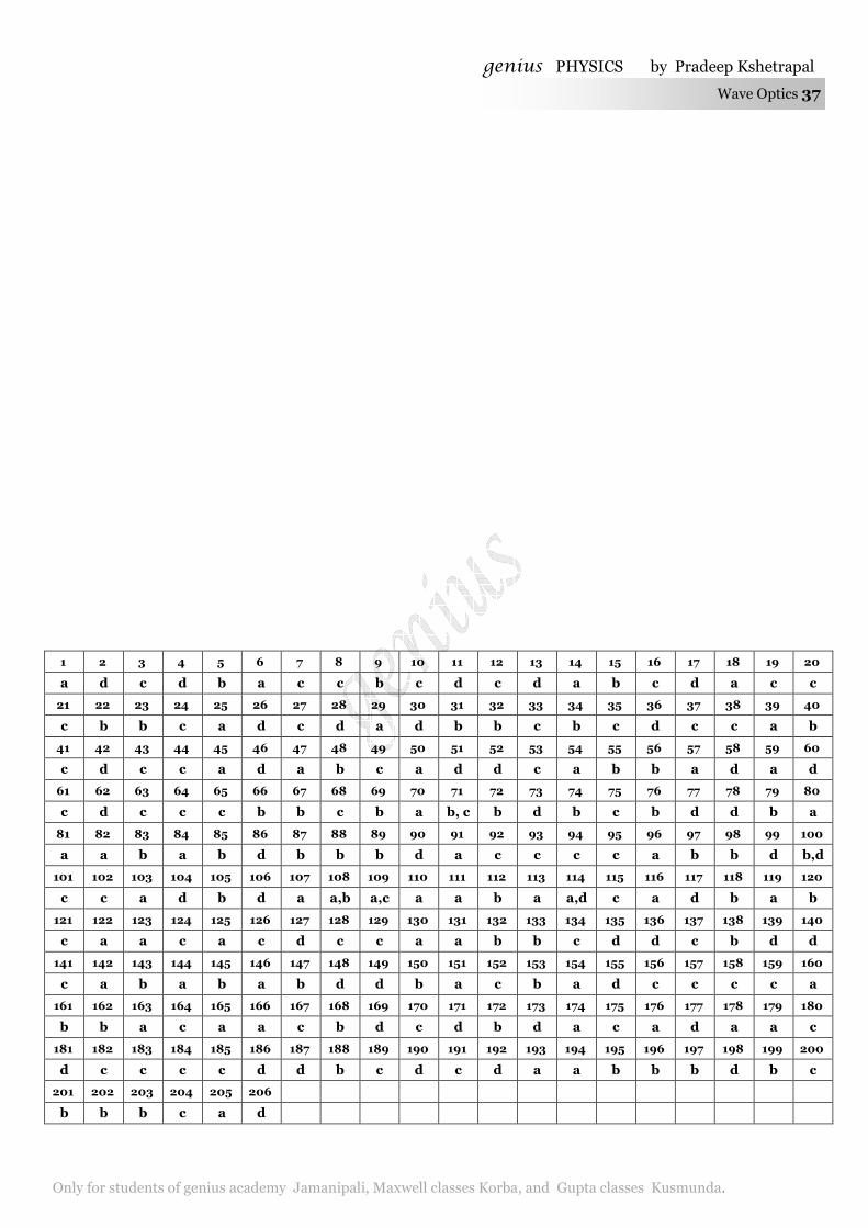
genius PHYSICS by Pradeep Kshetrapal
Only for students of genius academy Jamanipali, Maxwell classes Korba, and Gupta classes Kusmunda.
Wave Optics 37
1 2 3 4 5 6 7 8 9 10 11 12 13 14 15 16 17 18 19 20
a d c d b a c c b c d c d a b c d a c c
21 22 23 24 25 26 27 28 29 30 31 32 33 34 35 36 37 38 39 40
c b b c a d c d a d b b c b c d c c a b
41 42 43 44 45 46 47 48 49 50 51 52 53 54 55 56 57 58 59 60
c d c c a d a b c a d d c a b b a d a d
61 62 63 64 65 66 67 68 69 70 71 72 73 74 75 76 77 78 79 80
c d c c c b b c b a b, c b d b c b d d b a
81 82 83 84 85 86 87 88 89 90 91 92 93 94 95 96 97 98 99 100
a a b a b d b b b d a c c c c a b b d b,d
101 102 103 104 105 106 107 108 109 110 111 112 113 114 115 116 117 118 119 120
c c a d b d a a,b a,c a a b a a,d c a d b a b
121 122 123 124 125 126 127 128 129 130 131 132 133 134 135 136 137 138 139 140
c a a c a c d c c a a b b c d d c b d d
141 142 143 144 145 146 147 148 149 150 151 152 153 154 155 156 157 158 159 160
c a b a b a b d d b a c b a d c c c c a
161 162 163 164 165 166 167 168 169 170 171 172 173 174 175 176 177 178 179 180
b b a c a a c b d c d b d a c a d a a c
181 182 183 184 185 186 187 188 189 190 191 192 193 194 195 196 197 198 199 200
d c c c c d d b c d c d a a b b b d b c
201 202 203 204 205 206
b b b c a d


