1
Valtek Rotary Actuators
Spring CylinderValtek Rotary Actuators
2
Valtek Rotary Actuators
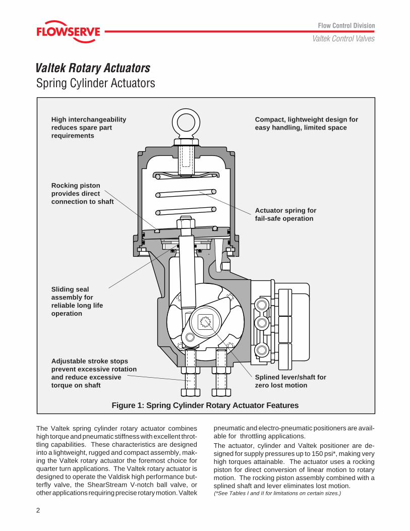
The Valtek spring cylinder rotary actuator combineshigh torque and pneumatic stiffness with excellent throt-tling capabilities. These characteristics are designedinto a lightweight, rugged and compact assembly, mak-ing the Valtek rotary actuator the foremost choice forquarter turn applications. The Valtek rotary actuator isdesigned to operate the Valdisk high performance but-terfly valve, the ShearStream V-notch ball valve, orother applications requiring precise rotary motion. Valtek
Spring Cylinder Actuators
Adjustable stroke stopsprevent excessive rotationand reduce excessivetorque on shaft
Compact, lightweight design foreasy handling, limited space
Rocking pistonprovides directconnection to shaft
Sliding sealassembly forreliable long lifeoperation
High interchangeabilityreduces spare partrequirements
Actuator spring forfail-safe operation
Splined lever/shaft forzero lost motion
Figure 1: Spring Cylinder Rotary Actuator Features
pneumatic and electro-pneumatic positioners are avail-able for throttling applications.The actuator, cylinder and Valtek positioner are de-signed for supply pressures up to 150 psi*, making veryhigh torques attainable. The actuator uses a rockingpiston for direct conversion of linear motion to rotarymotion. The rocking piston assembly combined with asplined shaft and lever eliminates lost motion.(*See Tables I and II for limitations on certain sizes.)
3
Valtek Rotary Actuators
Important features and advantages of the Valtek rotary spring cylinder actuator include:
Features Advantages
Accepts up to 150 psi • Achieves higher torques
• Obtains stiff piston positioning
• Permits higher ∆P limits on valve
Rocking piston • Provides direct connection to shaft
• Assures zero lost motion between actuator and valve
• Utilizes fewer parts
Splined shaft and lever • Allows zero lost motion
Compact, lightweight, rugged • Permits easy maintenance
• Installs in limited space applications
• Easily meets seismic requirements
Low friction bearings • Provide millions of cycles with minimal wear
• Combined with direct linkage, provides very low hysteresis
Field reversible • Requires no extra parts
• Permits fast, easy field reversing
• Requires no change of spring action
Fail-safe spring • Moves actuator to failure position without pressure assistance
Air-purged, fully enclosed • Prevents corrosion of linkage
• Ensures safe operation
• Contains external position indicator
• Allows four mounting positions without retubing, changing oradding parts
Stroke stops • Allow both ends of stroke to be adjusted
The Valtek rotary spring cylinder actuator also capitalizes on established features of other Valtek actuators:
Interchangeability • Minimizes requirements for stocking spare parts
• Reduces inventory costs
• Uses identical parts in differing rotary actuator sizes
• Utilizes many Valtek linear actuator parts
Spool-type four-way • Provides high-performance modulating positioner control
• Ensures ease of calibration and maintenance due to fewer parts
Valtek’s rotary spring cylinder actuator features high torques, positioning stiffness and easy maintenance to producea high-performance rotary actuator that excels in maintenance-free throttling and on/off control applications.
Features and Advantages
transfer case
air supply
Positioner
4
Valtek Rotary ActuatorsStiffness
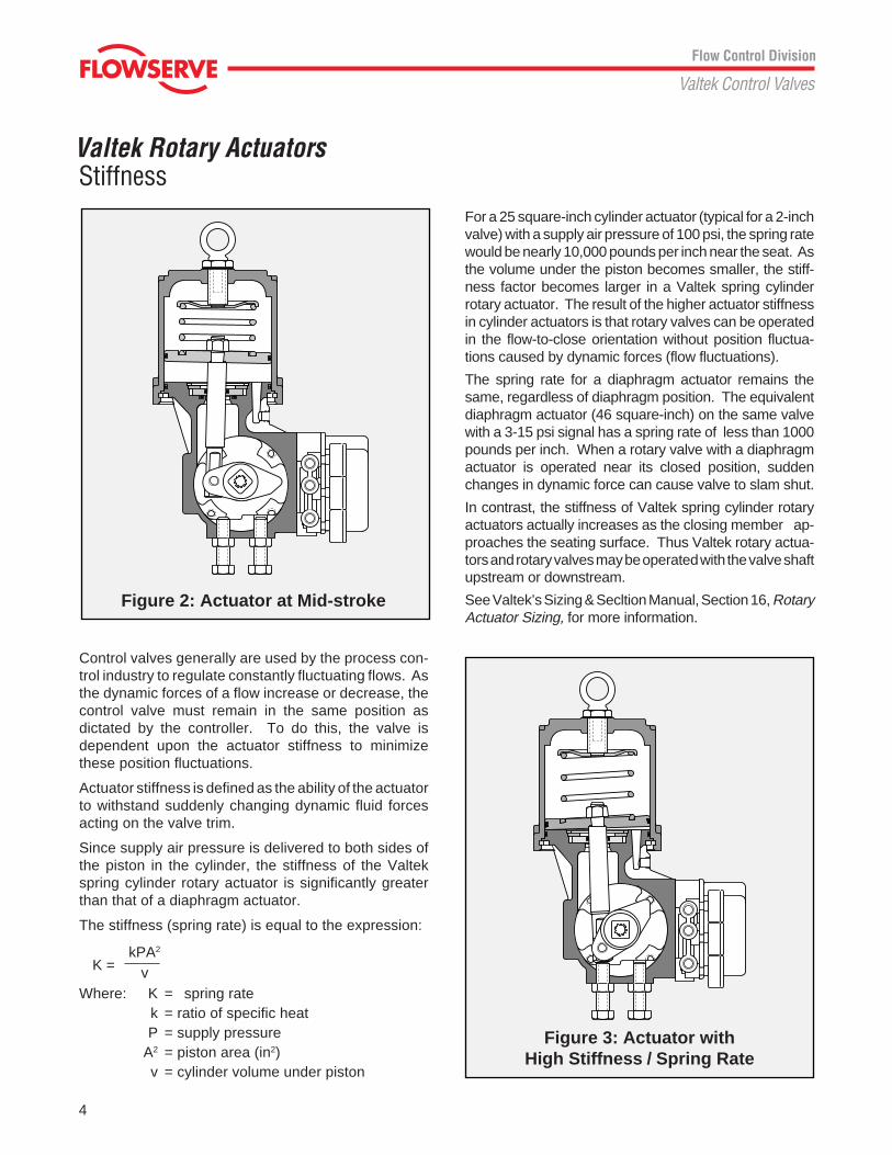
For a 25 square-inch cylinder actuator (typical for a 2-inchvalve) with a supply air pressure of 100 psi, the spring ratewould be nearly 10,000 pounds per inch near the seat. Asthe volume under the piston becomes smaller, the stiff-ness factor becomes larger in a Valtek spring cylinderrotary actuator. The result of the higher actuator stiffnessin cylinder actuators is that rotary valves can be operatedin the flow-to-close orientation without position fluctua-tions caused by dynamic forces (flow fluctuations).
The spring rate for a diaphragm actuator remains thesame, regardless of diaphragm position. The equivalentdiaphragm actuator (46 square-inch) on the same valvewith a 3-15 psi signal has a spring rate of less than 1000pounds per inch. When a rotary valve with a diaphragmactuator is operated near its closed position, suddenchanges in dynamic force can cause valve to slam shut.
In contrast, the stiffness of Valtek spring cylinder rotaryactuators actually increases as the closing member ap-proaches the seating surface. Thus Valtek rotary actua-tors and rotary valves may be operated with the valve shaftupstream or downstream.
See Valtek’s Sizing & Secltion Manual, Section 16, RotaryActuator Sizing, for more information.
K =
Control valves generally are used by the process con-trol industry to regulate constantly fluctuating flows. Asthe dynamic forces of a flow increase or decrease, thecontrol valve must remain in the same position asdictated by the controller. To do this, the valve isdependent upon the actuator stiffness to minimizethese position fluctuations.
Actuator stiffness is defined as the ability of the actuatorto withstand suddenly changing dynamic fluid forcesacting on the valve trim.
Since supply air pressure is delivered to both sides ofthe piston in the cylinder, the stiffness of the Valtekspring cylinder rotary actuator is significantly greaterthan that of a diaphragm actuator.
The stiffness (spring rate) is equal to the expression:
kPA2
vWhere: K = spring rate
k = ratio of specific heat P = supply pressureA2 = piston area (in2)v = cylinder volume under piston
Figure 2: Actuator at Mid-stroke
Figure 3: Actuator withHigh Stiffness / Spring Rate
5
Valtek Rotary ActuatorsPerformanceTorque Producing Capability
Valtek spring cylinder rotary actuators produce sub-stantially higher torque than comparable diaphragmactuators because the cylinder operates with supplypressures up to 150 psi. Throttling diaphragm actua-tors are limited to 40-60 psi, thus decreasing theirtorque-producing capability. Higher actuator air supply,coupled with high-pressure air on both sides of theactuator piston, provide exceptional stiffness for pre-cise throttling control. Valtek rotary actuator stiffness issufficient to control high pressure drops and to permitthe valve to throttle near the seat.
Cam Characterizable Operation
Valtek's standard Beta positioner, is provided with areversible cam that characterizes Valdisk's C
V to either
modified equal percent or linear performance. Thesame cam enhances the ShearStream control valve'sinherent equal percent characteristic.A second rotary cam is also available. This optionalcam gives ShearStream valves a linear relationship ofrotation with respect to the controller signal. It isreversible for use in air-to-close or air-to-open, fail-open applications and is also linear in this mode.
Speed and Sensitivity
High air-handling capacity of the positioner, combinedwith relatively low cylinder volumes, produces faststroking speeds. High operating speed is achieved withvirtually no overshoot when approaching the final discor ball position. At the same time, static sensitivity of theunit is excellent. For example, as little as 0.017 psi isrequired to rotate the shaft 0.01 degrees (the minimumdetectable movement in the tests conducted) on a size25 actuator. A signal change of only 0.02 psi is requiredto reverse the shaft motion.
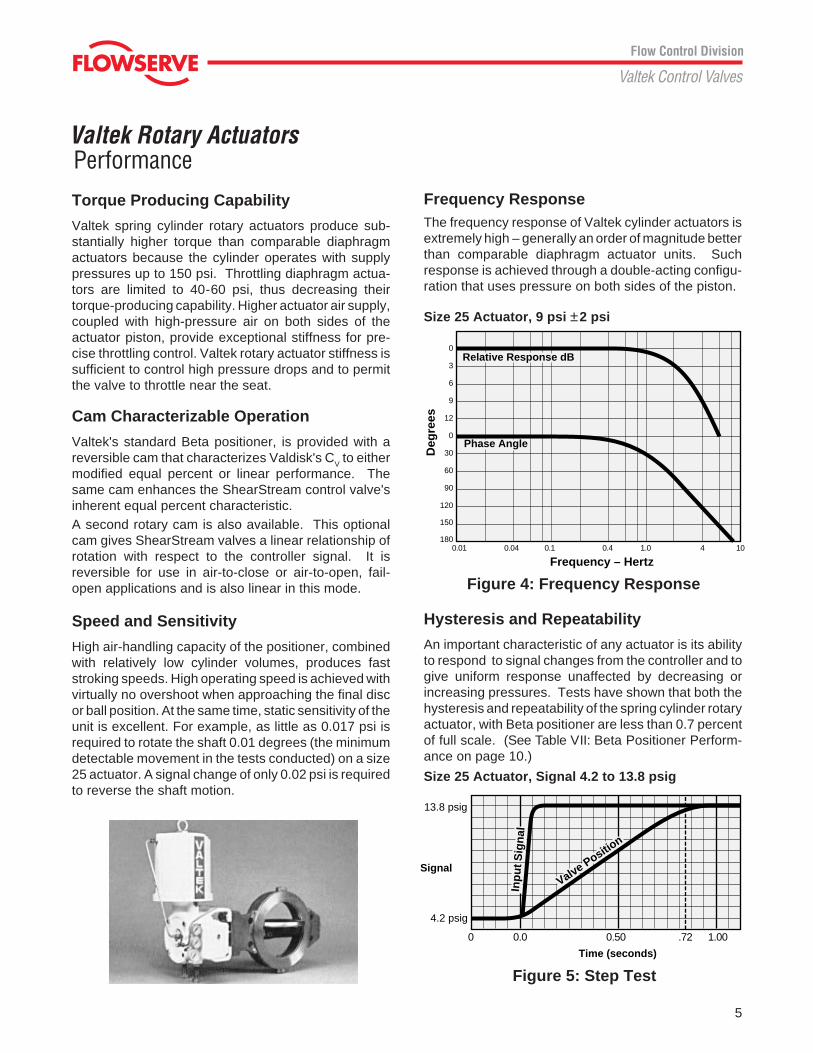
Frequency ResponseThe frequency response of Valtek cylinder actuators isextremely high – generally an order of magnitude betterthan comparable diaphragm actuator units. Suchresponse is achieved through a double-acting configu-ration that uses pressure on both sides of the piston.
Size 25 Actuator, 9 psi ±2 psi
0
3
6
9
12
0
30
60
90
120
150
1800.01 0.04 0.1 0.4 1.0 4 10
Phase Angle
Relative Response dB
Deg
rees
Frequency – Hertz
Hysteresis and Repeatability
An important characteristic of any actuator is its abilityto respond to signal changes from the controller and togive uniform response unaffected by decreasing orincreasing pressures. Tests have shown that both thehysteresis and repeatability of the spring cylinder rotaryactuator, with Beta positioner are less than 0.7 percentof full scale. (See Table VII: Beta Positioner Perform-ance on page 10.)
Figure 4: Frequency Response
Figure 5: Step Test
Size 25 Actuator, Signal 4.2 to 13.8 psig
0 0.0 0.50 .72 1.00
SignalValve Positio
n
Inp
ut
Sig
nal
13.8 psig
4.2 psig
Time (seconds)
6
Valtek Rotary Actuators
Table I: Net Torque Output of Actuators at Various Supply Pressures, (in.-lb.)
Degrees from Fail Position on Air Supply Loss
0 10 20 30 40 50 60 70 80 90STD 25 with 150 3013 3399 3700 3907 4000 3970 3811 3514 3084 2532STD Spring 140 3808 3165 3444 3631 3714 3685 3531 3253 2854 2339
120 2397 2695 2928 3080 3145 3110 2972 2731 2390 1962100 1986 2228 2412 2530 2573 2535 2414 2211 1928 157780 1574 1759 1896 1979 2002 1961 1856 1688 1463 119160 1163 1290 1381 1428 1430 1386 1298 1167 1001 806
Spring Torque 72 115 167 225 284 338 379 399 391 349
STD 25 with 150 2647 2973 3223 3386 3448 3403 3246 2976 2600 2124HD Spring 140 2441 2738 2964 3110 3162 3115 2966 2716 2368 1931
120 2030 2270 2450 2558 2590 2542 2409 2195 1905 1552100 1618 1802 1934 2009 2020 1967 1850 1673 1441 116780 1206 1333 1418 1457 1448 1392 1292 1151 978 78160 795 865 902 907 877 818 733 630 515 396
Spring Torque 440 542 647 749 839 908 945 937 878 758
STD 50 with 150 10701 11981 13015 13751 14134 14089 13575 12568 11043 9035STD Spring 140 9970 11157 12114 12798 13136 13083 12596 11653 10232 8365
120 8516 9513 10318 10874 11141 11075 10649 9826 8615 7053100 7059 7873 8515 8953 9153 9073 8693 7999 6995 571280 5602 6227 6716 7033 7156 7062 6736 6174 5372 437360 4147 4586 4913 5114 5166 5058 4784 4347 3755 3034
Spring Torque 222 343 489 651 816 966 1081 1134 1107 983
STD 50 with 150 9774 10898 11781 12380 12651 12533 12000 11036 9648 7850HD Spring 140 9044 10074 10880 11425 11652 11527 11021 10122 8837 7183
120 7591 8430 9083 9502 9657 9519 9073 8300 7216 5865100 6133 6790 7281 7585 7668 7516 7117 6473 5597 452780 4678 5148 5481 5660 5671 5508 5163 4646 3974 318660 3223 3505 3681 3741 3680 3501 3209 2821 2356 1846
Spring Torque 1148 1428 1726 2026 2304 2529 2662 2667 2511 2167
STD 100 with 150 26194 29415 32022 33847 34730 34559 33234 30711 26943 22035STD Spring 140 24385 27397 29784 31459 32253 32069 30831 28446 26936 20378
120 20805 23329 25330 26685 27303 27104 25983 23921 20932 17119100 17226 19271 20859 21914 22368 22119 21134 19394 16920 1380880 13640 15200 16399 17153 17413 17133 16296 14878 12915 1048560 10055 11139 11929 12391 12472 12159 11447 10350 8901 7167
Spring Torque 704 1049 1461 1913 2370 2783 3088 3225 3135 2775
STD 100 with 150 24678 27231 29008 29925 29917 28969 27058 24266 20699 16483Dual Springs 140 22881 25195 26771 27539 27459 26475 24632 22001 18691 14832
120 19304 21127 22317 22784 22507 21490 19782 17472 14680 11563100 15713 17070 17847 18012 17567 16518 14946 12956 10674 824580 12130 12999 13385 13248 12612 11538 10101 8432 6662 492760 8545 8939 8921 8483 7673 6558 5257 3910 2662 1611
Spring Torque 2217 3256 4485 5831 7185 8405 9299 9691 9407 8316
STD 200 with 80* 27695 31132 33903 35838 36820 36663 35280 32620 28633 23416STD Spring 70 24156 27119 29480 31134 31916 31730 30501 28139 25670 20206
60 20595 23091 25069 26406 27014 26813 25699 24656 20697 1692650 17051 19072 20643 21696 22126 21876 20897 19173 16724 13646
Spring Torque 704 1049 1461 1913 2370 2783 3088 3225 3135 2775
STD 200 with 80* 26192 28930 30894 31940 32005 31052 29104 26177 22393 17887Dual Springs 70 22636 24918 26467 27214 27122 26136 24302 21693 18420 14650
60 19094 20889 22056 22505 22217 21198 19499 17208 14445 1137050 15538 16872 17629 17779 17326 16275 14709 12735 10478 8083
Spring Torque 2217 3256 4485 5831 7185 8405 9299 9691 9407 8316
NOTE: For air-to-open/fail-closed actuators the 0 degree position shown above corresponds to the disc or ball being seated.For air-to-close/fail-open actuators the 90 degree position shown above corresponds to the disc or ball being seated.* Size 200 actuator limited to 80 psi air supply pressure
Torque Output
Actuator Supply Size Pressure
7
Valtek Rotary Actuators
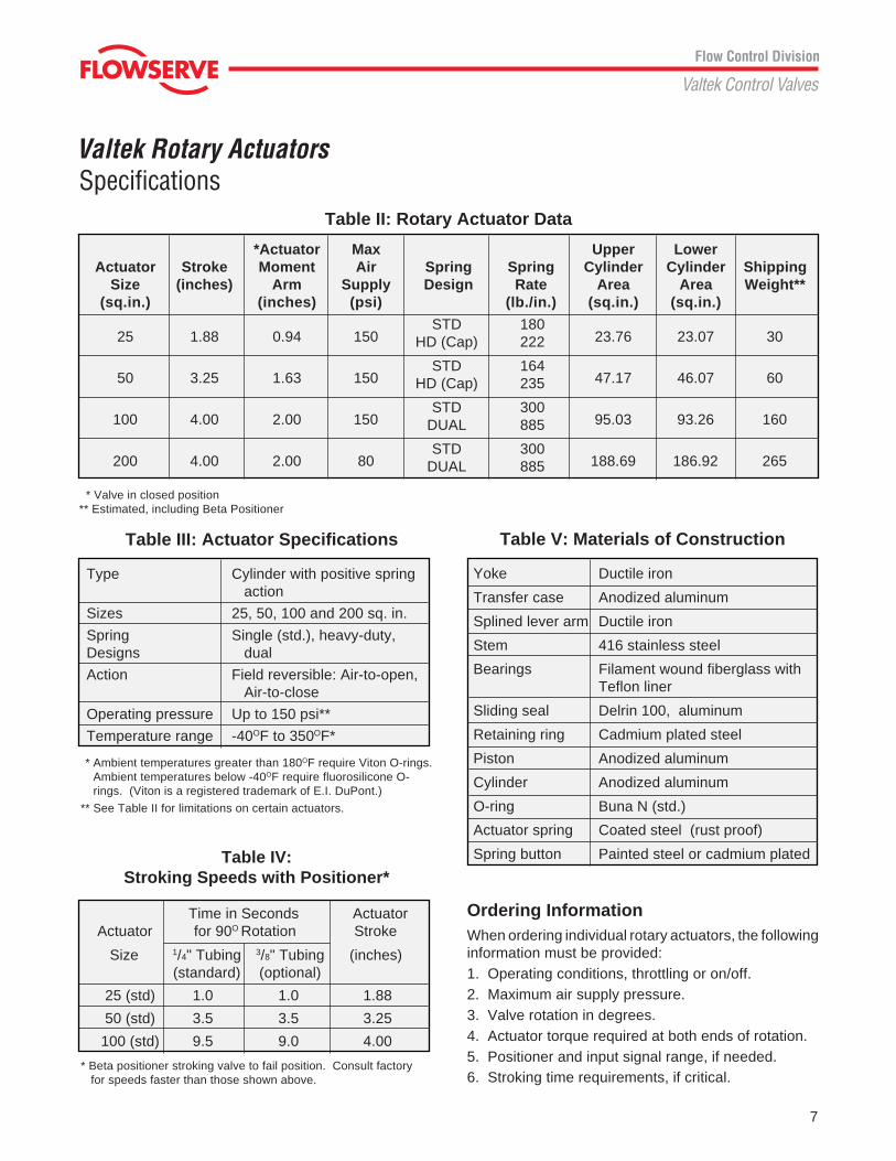
Table IV:Stroking Speeds with Positioner*
Time in Seconds Actuator Actuator for 90O Rotation Stroke
Size 1/4" Tubing 3/8" Tubing (inches)(standard) (optional)
25 (std) 1.0 1.0 1.88
50 (std) 3.5 3.5 3.25
100 (std) 9.5 9.0 4.00
* Beta positioner stroking valve to fail position. Consult factory for speeds faster than those shown above.
Table V: Materials of Construction
Yoke Ductile iron
Transfer case Anodized aluminum
Splined lever arm Ductile iron
Stem 416 stainless steel
Bearings Filament wound fiberglass withTeflon liner
Sliding seal Delrin 100, aluminum
Retaining ring Cadmium plated steel
Piston Anodized aluminum
Cylinder Anodized aluminum
O-ring Buna N (std.)
Actuator spring Coated steel (rust proof)
Spring button Painted steel or cadmium plated
Table III: Actuator Specifications
Type Cylinder with positive spring action
Sizes 25, 50, 100 and 200 sq. in.
Spring Single (std.), heavy-duty,Designs dual
Action Field reversible: Air-to-open, Air-to-close
Operating pressure Up to 150 psi**
Temperature range -40OF to 350OF*
* Ambient temperatures greater than 180OF require Viton O-rings.Ambient temperatures below -40OF require fluorosilicone O-rings. (Viton is a registered trademark of E.I. DuPont.)
** See Table II for limitations on certain actuators.
Table II: Rotary Actuator Data
*Actuator Max Upper LowerActuator Stroke Moment Air Spring Spring Cylinder Cylinder Shipping
Size (inches) Arm Supply Design Rate Area Area Weight**(sq.in.) (inches) (psi) (lb./in.) (sq.in.) (sq.in.)
25 1.88 0.94 150 23.76 23.07 30
50 3.25 1.63 150 47.17 46.07 60
100 4.00 2.00 150 95.03 93.26 160
200 4.00 2.00 80 188.69 186.92 265
* Valve in closed position** Estimated, including Beta Positioner
Specifications
Ordering InformationWhen ordering individual rotary actuators, the followinginformation must be provided:1. Operating conditions, throttling or on/off.2. Maximum air supply pressure.3. Valve rotation in degrees.4. Actuator torque required at both ends of rotation.5. Positioner and input signal range, if needed.6. Stroking time requirements, if critical.
STD 180HD (Cap) 222
STD 164HD (Cap) 235
STD 300DUAL 885
STD 300DUAL 885
8
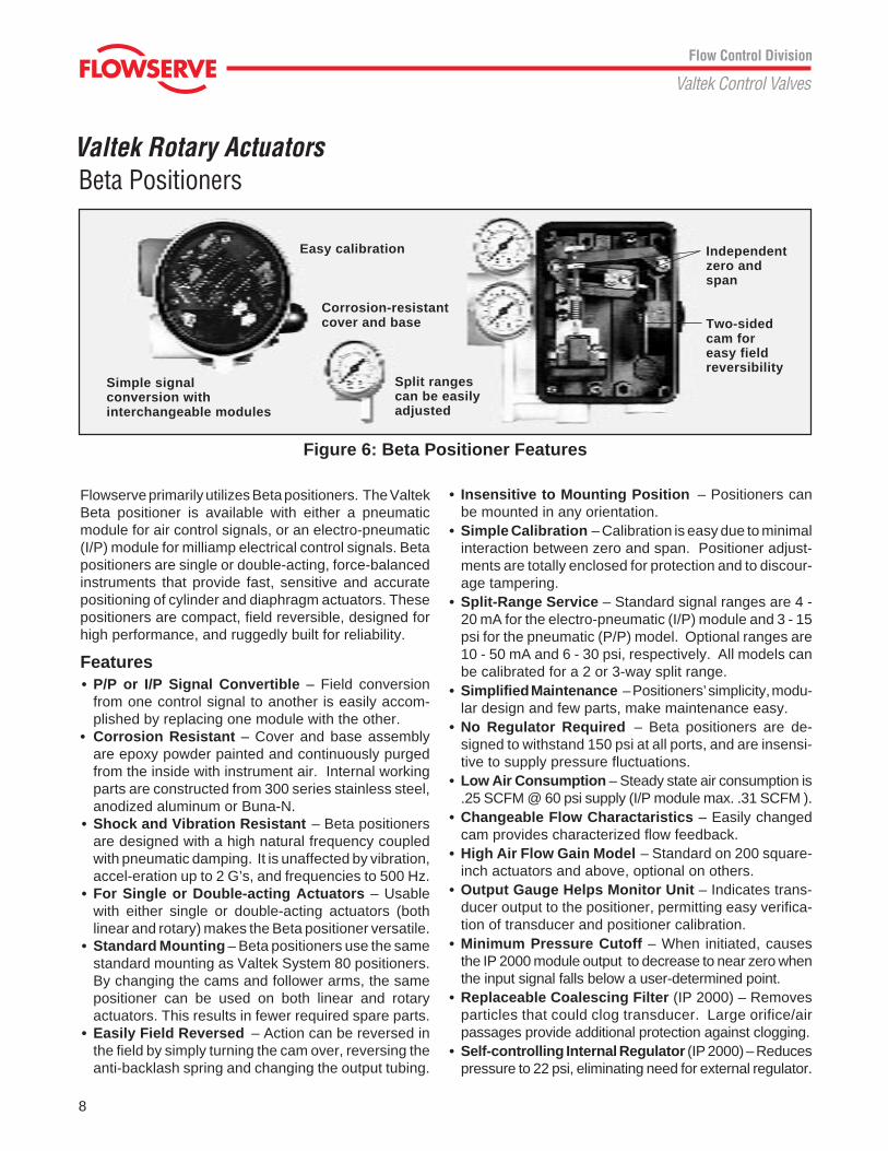
Valtek Rotary ActuatorsBeta Positioners
Flowserve primarily utilizes Beta positioners. The ValtekBeta positioner is available with either a pneumaticmodule for air control signals, or an electro-pneumatic(I/P) module for milliamp electrical control signals. Betapositioners are single or double-acting, force-balancedinstruments that provide fast, sensitive and accuratepositioning of cylinder and diaphragm actuators. Thesepositioners are compact, field reversible, designed forhigh performance, and ruggedly built for reliability.
Features• P/P or I/P Signal Convertible – Field conversion
from one control signal to another is easily accom-plished by replacing one module with the other.
• Corrosion Resistant – Cover and base assemblyare epoxy powder painted and continuously purgedfrom the inside with instrument air. Internal workingparts are constructed from 300 series stainless steel,anodized aluminum or Buna-N.
• Shock and Vibration Resistant – Beta positionersare designed with a high natural frequency coupledwith pneumatic damping. It is unaffected by vibration,accel-eration up to 2 G’s, and frequencies to 500 Hz.
• For Single or Double-acting Actuators – Usablewith either single or double-acting actuators (bothlinear and rotary) makes the Beta positioner versatile.
• Standard Mounting – Beta positioners use the samestandard mounting as Valtek System 80 positioners.By changing the cams and follower arms, the samepositioner can be used on both linear and rotaryactuators. This results in fewer required spare parts.
• Easily Field Reversed – Action can be reversed inthe field by simply turning the cam over, reversing theanti-backlash spring and changing the output tubing.
• Insensitive to Mounting Position – Positioners canbe mounted in any orientation.
• Simple Calibration – Calibration is easy due to minimalinteraction between zero and span. Positioner adjust-ments are totally enclosed for protection and to discour-age tampering.
• Split-Range Service – Standard signal ranges are 4 -20 mA for the electro-pneumatic (I/P) module and 3 - 15psi for the pneumatic (P/P) model. Optional ranges are10 - 50 mA and 6 - 30 psi, respectively. All models canbe calibrated for a 2 or 3-way split range.
• Simplified Maintenance – Positioners’ simplicity, modu-lar design and few parts, make maintenance easy.
• No Regulator Required – Beta positioners are de-signed to withstand 150 psi at all ports, and are insensi-tive to supply pressure fluctuations.
• Low Air Consumption – Steady state air consumption is.25 SCFM @ 60 psi supply (I/P module max. .31 SCFM ).
• Changeable Flow Charactaristics – Easily changedcam provides characterized flow feedback.
• High Air Flow Gain Model – Standard on 200 square-inch actuators and above, optional on others.
• Output Gauge Helps Monitor Unit – Indicates trans-ducer output to the positioner, permitting easy verifica-tion of transducer and positioner calibration.
• Minimum Pressure Cutoff – When initiated, causesthe IP 2000 module output to decrease to near zero whenthe input signal falls below a user-determined point.
• Replaceable Coalescing Filter (IP 2000) – Removesparticles that could clog transducer. Large orifice/airpassages provide additional protection against clogging.
• Self-controlling Internal Regulator (IP 2000) – Reducespressure to 22 psi, eliminating need for external regulator.
Simple signalconversion withinterchangeable modules
Split rangescan be easilyadjusted
Easy calibration Independentzero andspan
Two-sidedcam foreasy fieldreversibility
Figure 6: Beta Positioner Features
Corrosion-resistantcover and base
9
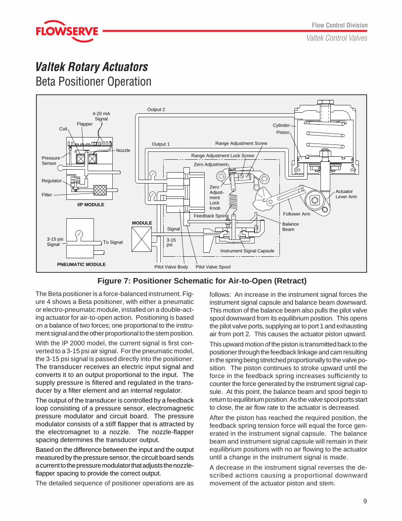
Valtek Rotary ActuatorsBeta Positioner Operation
The Beta positioner is a force-balanced instrument. Fig-ure 4 shows a Beta positioner, with either a pneumaticor electro-pneumatic module, installed on a double-act-ing actuator for air-to-open action. Positioning is basedon a balance of two forces; one proportional to the instru-ment signal and the other proportional to the stem position.
With the IP 2000 model, the current signal is first con-verted to a 3-15 psi air signal. For the pneumatic model,the 3-15 psi signal is passed directly into the positioner.The transducer receives an electric input signal andconverts it to an output proportional to the input. Thesupply pressure is filtered and regulated in the trans-ducer by a filter element and an internal regulator.
The output of the transducer is controlled by a feedbackloop consisting of a pressure sensor, electromagneticpressure modulator and circuit board. The pressuremodulator consists of a stiff flapper that is attracted bythe electromagnet to a nozzle. The nozzle-flapperspacing determines the transducer output.
Based on the difference between the input and the outputmeasured by the pressure sensor, the circuit board sendsa current to the pressure modulator that adjusts the nozzle-flapper spacing to provide the correct output.
The detailed sequence of positioner operations are as
follows: An increase in the instrument signal forces theinstrument signal capsule and balance beam downward.This motion of the balance beam also pulls the pilot valvespool downward from its equilibrium position. This opensthe pilot valve ports, supplying air to port 1 and exhaustingair from port 2. This causes the actuator piston upward.
This upward motion of the piston is transmitted back to thepositioner through the feedback linkage and cam resultingin the spring being stretched proportionally to the valve po-sition. The piston continues to stroke upward until theforce in the feedback spring increases sufficiently tocounter the force generated by the instrument signal cap-sule. At this point, the balance beam and spool begin toreturn to equilibrium position. As the valve spool ports startto close, the air flow rate to the actuator is decreased.
After the piston has reached the required position, thefeedback spring tension force will equal the force gen-erated in the instrument signal capsule. The balancebeam and instrument signal capsule will remain in theirequilibrium positions with no air flowing to the actuatoruntil a change in the instrument signal is made.
A decrease in the instrument signal reverses the de-scribed actions causing a proportional downwardmovement of the actuator piston and stem.
Figure 7: Positioner Schematic for Air-to-Open (Retract)
C
+ –
Output 2
Output 1
Range Adjustment Lock Screw
Piston
Cylinder
Follower Arm
ActuatorLever Arm
BalanceBeam
Instrument Signal Capsule
Pilot Valve SpoolPilot Valve Body
3-15psi
SignalMODULE
To Signal3-15 psiSignal
4-20 mASignal
FlapperCoil
PressureSensor
Regulator
Filter
I/P MODULE
Zero Adjustment
ZeroAdjust-mentLockKnob
Feedback Spring
Range Adjustment Screw
PNEUMATIC MODULE
Nozzle
10
Valtek Rotary Actuators
Pneumatic IP 2000Module Module
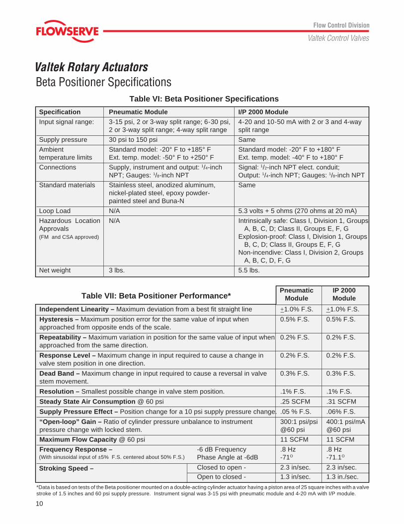
Independent Linearity – Maximum deviation from a best fit straight line +1.0% F.S. +1.0% F.S.
Hysteresis – Maximum position error for the same value of input when 0.5% F.S. 0.5% F.S.approached from opposite ends of the scale.
Repeatability – Maximum variation in position for the same value of input when 0.2% F.S. 0.2% F.S.approached from the same direction.
Response Level – Maximum change in input required to cause a change in 0.2% F.S. 0.2% F.S.valve stem position in one direction.
Dead Band – Maximum change in input required to cause a reversal in valve 0.3% F.S. 0.3% F.S.stem movement.
Resolution – Smallest possible change in valve stem position. .1% F.S. .1% F.S.
Steady State Air Consumption @ 60 psi .25 SCFM .31 SCFM
Supply Pressure Effect – Position change for a 10 psi supply pressure change. .05 % F.S. .06% F.S.
“Open-loop” Gain – Ratio of cylinder pressure unbalance to instrument 300:1 psi/psi 400:1 psi/mApressure change with locked stem. @60 psi @60 psi
Maximum Flow Capacity @ 60 psi 11 SCFM 11 SCFM
Frequency Response – -6 dB Frequency .8 Hz .8 HzPhase Angle at -6dB -71O -71.1O
Closed to open - 2.3 in/sec. 2.3 in/sec.Open to closed - 1.3 in/sec. 1.3 in./sec.
*Data is based on tests of the Beta positioner mounted on a double-acting cylinder actuator having a piston area of 25 square inches with a valvestroke of 1.5 inches and 60 psi supply pressure. Instrument signal was 3-15 psi with pneumatic module and 4-20 mA with I/P module.
Table VI: Beta Positioner Specifications
Specification Pneumatic Module I/P 2000 Module
Input signal range: 3-15 psi, 2 or 3-way split range; 6-30 psi, 4-20 and 10-50 mA with 2 or 3 and 4-way2 or 3-way split range; 4-way split range split range
Supply pressure 30 psi to 150 psi Same
Ambient Standard model: -20° F to +185° F Standard model: -20° F to +180° Ftemperature limits Ext. temp. model: -50° F to +250° F Ext. temp. model: -40° F to +180° FConnections Supply, instrument and output: 1/4-inch Signal: 1/2-inch NPT elect. conduit;
NPT; Gauges: 1/8-inch NPT Output: 1/4-inch NPT; Gauges: 1/8-inch NPT
Standard materials Stainless steel, anodized aluminum, Samenickel-plated steel, epoxy powder-painted steel and Buna-N
Loop Load N/A 5.3 volts + 5 ohms (270 ohms at 20 mA)
Hazardous Location N/A Intrinsically safe: Class I, Division 1, GroupsApprovals A, B, C, D; Class II, Groups E, F, G(FM and CSA approved) Explosion-proof: Class I, Division 1, Groups
B, C, D; Class II, Groups E, F, GNon-incendive: Class I, Division 2, Groups
A, B, C, D, F, G
Net weight 3 lbs. 5.5 lbs.
Beta Positioner Specifications
(With sinusoidal input of ±5% F.S. centered about 50% F.S.)
Stroking Speed –
Table VII: Beta Positioner Performance*
11
Valtek Rotary ActuatorsOptions
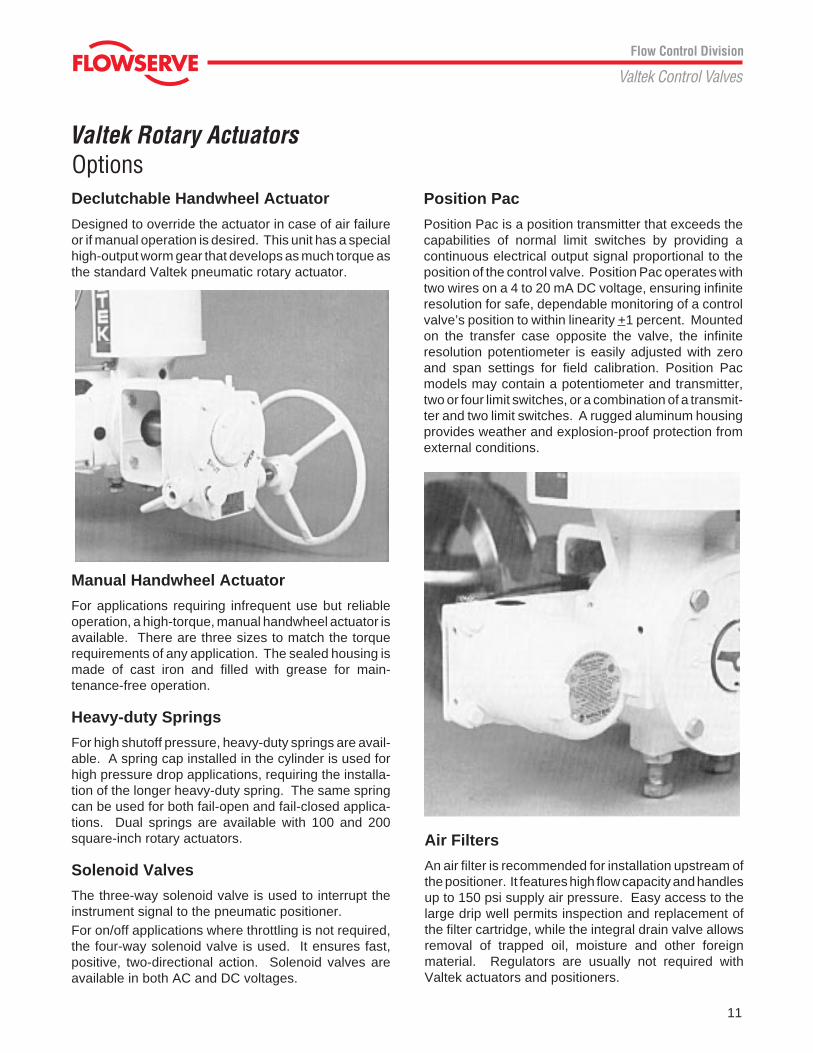
Position Pac
Position Pac is a position transmitter that exceeds thecapabilities of normal limit switches by providing acontinuous electrical output signal proportional to theposition of the control valve. Position Pac operates withtwo wires on a 4 to 20 mA DC voltage, ensuring infiniteresolution for safe, dependable monitoring of a controlvalve’s position to within linearity +1 percent. Mountedon the transfer case opposite the valve, the infiniteresolution potentiometer is easily adjusted with zeroand span settings for field calibration. Position Pacmodels may contain a potentiometer and transmitter,two or four limit switches, or a combination of a transmit-ter and two limit switches. A rugged aluminum housingprovides weather and explosion-proof protection fromexternal conditions.
Declutchable Handwheel Actuator
Designed to override the actuator in case of air failureor if manual operation is desired. This unit has a specialhigh-output worm gear that develops as much torque asthe standard Valtek pneumatic rotary actuator.
Air Filters
An air filter is recommended for installation upstream ofthe positioner. It features high flow capacity and handlesup to 150 psi supply air pressure. Easy access to thelarge drip well permits inspection and replacement ofthe filter cartridge, while the integral drain valve allowsremoval of trapped oil, moisture and other foreignmaterial. Regulators are usually not required withValtek actuators and positioners.
Manual Handwheel Actuator
For applications requiring infrequent use but reliableoperation, a high-torque, manual handwheel actuator isavailable. There are three sizes to match the torquerequirements of any application. The sealed housing ismade of cast iron and filled with grease for main-tenance-free operation.
Heavy-duty Springs
For high shutoff pressure, heavy-duty springs are avail-able. A spring cap installed in the cylinder is used forhigh pressure drop applications, requiring the installa-tion of the longer heavy-duty spring. The same springcan be used for both fail-open and fail-closed applica-tions. Dual springs are available with 100 and 200square-inch rotary actuators.
Solenoid Valves
The three-way solenoid valve is used to interrupt theinstrument signal to the pneumatic positioner.For on/off applications where throttling is not required,the four-way solenoid valve is used. It ensures fast,positive, two-directional action. Solenoid valves areavailable in both AC and DC voltages.
12
Valtek Rotary Actuators
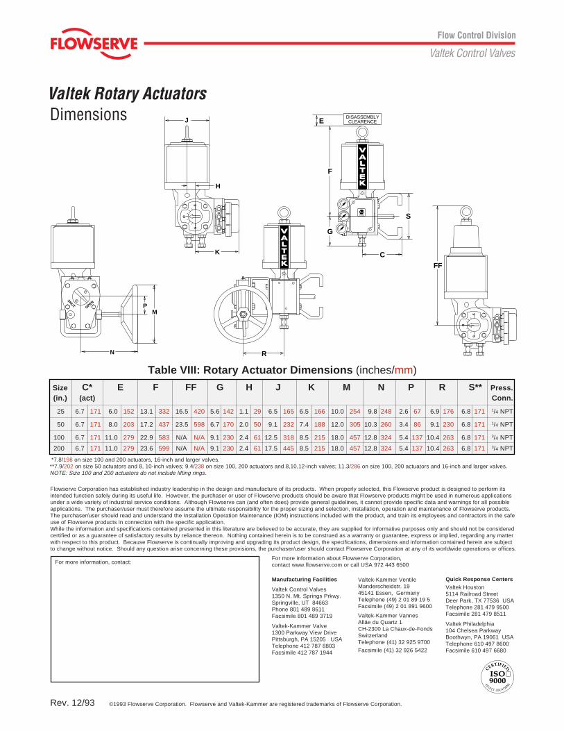
Table VIII: Rotary Actuator Dimensions (inches/mm)
Size C* E F FF G H J K M N P R S** Press.(in.) (act) Conn.
25 6.7 171 6.0 152 13.1 332 16.5 420 5.6 142 1.1 29 6.5 165 6.5 166 10.0 254 9.8 248 2.6 67 6.9 176 6.8 171 1/4 NPT
50 6.7 171 8.0 203 17.2 437 23.5 598 6.7 170 2.0 50 9.1 232 7.4 188 12.0 305 10.3 260 3.4 86 9.1 230 6.8 171 1/4 NPT
100 6.7 171 11.0 279 22.9 583 N/A N/A 9.1 230 2.4 61 12.5 318 8.5 215 18.0 457 12.8 324 5.4 137 10.4 263 6.8 171 3/4 NPT
200 6.7 171 11.0 279 23.6 599 N/A N/A 9.1 230 2.4 61 17.5 445 8.5 215 18.0 457 12.8 324 5.4 137 10.4 263 6.8 171 3/4 NPT
*7.8/198 on size 100 and 200 actuators, 16-inch and larger valves.**7.9/202 on size 50 actuators and 8, 10-inch valves; 9.4/238 on size 100, 200 actuators and 8,10,12-inch valves; 11.3/286 on size 100, 200 actuators and 16-inch and larger valves.NOTE: Size 100 and 200 actuators do not include lifting rings.
Dimensions
Rev. 12/93
R
SHUT
OPENP
N
M
O
SS
H
K
J
F
G
C
S
DISASSEMBLYCLEARENCEE
O
SS
FF
ISO 9000
CERTIFIED
SELECT LOCATIO
NS
Flowserve Corporation has established industry leadership in the design and manufacture of its products. When properly selected, this Flowserve product is designed to perform itsintended function safely during its useful life. However, the purchaser or user of Flowserve products should be aware that Flowserve products might be used in numerous applicationsunder a wide variety of industrial service conditions. Although Flowserve can (and often does) provide general guidelines, it cannot provide specific data and warnings for all possibleapplications. The purchaser/user must therefore assume the ultimate responsibility for the proper sizing and selection, installation, operation and maintenance of Flowserve products.The purchaser/user should read and understand the Installation Operation Maintenance (IOM) instructions included with the product, and train its employees and contractors in the safeuse of Flowserve products in connection with the specific application.While the information and specifications contained presented in this literature are believed to be accurate, they are supplied for informative purposes only and should not be consideredcertified or as a guarantee of satisfactory results by reliance thereon. Nothing contained herein is to be construed as a warranty or guarantee, express or implied, regarding any matterwith respect to this product. Because Flowserve is continually improving and upgrading its product design, the specifications, dimensions and information contained herein are subjectto change without notice. Should any question arise concerning these provisions, the purchaser/user should contact Flowserve Corporation at any of its worldwide operations or offices.
For more information, contact:For more information about Flowserve Corporation,contact www.flowserve.com or call USA 972 443 6500
Manufacturing Facilities
Valtek Control Valves1350 N. Mt. Springs Prkwy.Springville, UT 84663Phone 801 489 8611Facsimile 801 489 3719
Valtek-Kammer Valve1300 Parkway View DrivePittsburgh, PA 15205 USATelephone 412 787 8803Facsimile 412 787 1944
Valtek-Kammer VentileManderscheidstr. 1945141 Essen, GermanyTelephone (49) 2 01 89 19 5Facsimile (49) 2 01 891 9600
Valtek-Kammer VannesAlläe du Quartz 1CH-2300 La Chaux-de-FondsSwitzerlandTelephone (41) 32 925 9700
Facsimile (41) 32 926 5422
©1993 Flowserve Corporation. Flowserve and Valtek-Kammer are registered trademarks of Flowserve Corporation.
Quick Response CentersValtek Houston5114 Railroad StreetDeer Park, TX 77536 USATelephone 281 479 9500Facsimile 281 479 8511
Valtek Philadelphia104 Chelsea ParkwayBoothwyn, PA 19061 USATelephone 610 497 8600Facsimile 610 497 6680


