
Experience In Motion
Spring Diaphragm Rotary ActuatorsFCD VLAIM050-01 – 05/12
InstallationOperation
Maintenance
USER INSTRUCTIONS

2
Spring Diaphragm Rotary Actuators FCD VLAIM050-01 – 05/12
ContentsGeneral Information 3
Unpacking 4
Installation 4
Changing Air Action 4
Sectional View of Spring Diaphragm Rotary Actuator 6
Replacing the Diaphragm, Without Removing the Diaphragm Box 7
Replacing the Spring or Diaphragm 8
Exploded View of Spring Diaphragm Rotary Actuator 9
Mounting Orientations 10
Spring Diaphragm Rotary Actuator 10
Troubleshooting Rotary Actuators 11

3
flowserve.com
Spring Diaphragm Rotary Actuators FCD VLAIM050-01 – 05/12
Terms Concerning SafetyThe safety terms DANGER, WARNING, CAUTION and NOTE are used in these instructions to highlight particular dangers and/or to provide additional information on aspects that may not be readily apparent.
DANGER: indicates that death, severe personal injury and/or substantial property damage will occur if proper precautions are not taken.
WARNING: indicates that death, severe personal injury and/or substantial property damage can occur if proper precautions are not taken.
CAUTION: indicates that minor personal injury and/or property damage can occur if proper precautions are not taken.
NOTE: indicates and provides additional technical information, which may not be very obvious even to qualified personnel. Compliance with other, not particularly emphasized notes, with regard to transport, assembly, operation and maintenance and with regard to technical documentation (e.g. in the operating instruction, product documentation or on the product itself) is essential, in order to avoid faults, which in themselves might directly or indirectly cause severe personal injury or property damage.
General InformationThe following instructions are designed to assist in unpacking, installing and performing maintenance as required on Flowserve Spring Diaphragm Rotary Actuators. Product users and maintenance personnel should throroughly review this bulletin prior to installing, operating or performing any maintenance on the actuator. Separate maintenance instructions cover additional components, such as Valdisk and ShearStream body com ponents, MaxFlo 3, Valdisk and ShearStream body assemblies, fail-safe systems, limit switches, handlevers, position transmitters and handwheels.
This publication does not contain information on Flowserve positioners. Refer to the appropriate maintenance bulletin for installing, calibrating, maintaining, troubleshooting and operating Flowserve positioners.
To avoid possible injury to personnel or damage to valve parts, WARNING and CAUTION notes must be strictly followed. Modifying this product, substituting non-factory parts or using maintenance procedures other than outlined could drastically affect performance and be hazardous to personnel and equipment.

Spring Diaphragm Rotary Actuators FCD VLAIM050-01 – 05/12
4
Unpacking1. While unpacking the actuator, check the packing list against the materials received.
2. When lifting the actuator from the shipping container, position lifting straps and hoist to avoid damage to tubing and mounted accessories.
WARNING: When lifting an actuator with lifting straps, be aware the center of gravity may be above the lifting point. Therefore, support must be given to prevent the actuator from rotating. Failure to do so can cause serious injury to personnel and damage to actuator or nearby equipment.
3. Contact your shipper immediately for any shipping damage.
4. Contact your Flowserve representative for any problems.
InstallationNotice that the NR actuator has (4) rubber plugs (436) in the diaphragm box (202). These rubber plugs (436) function as a drain. After the valve is installed, remove one of the 4 plugs (436) that will allow any moisture that develops in the diaphragm box to drain out. Leave the other 3 plugs in place.
Changing Air Action Follow all steps carefully, actuator spring is under compression
1. Position valve vertically
• Itiseasiertochangetheairactionwiththevalveinthisposition.
2. Remove cover plates and positioner
• Removethe(4)bolts(337)inthecoverplateandremove the cover plate (363). Remove the (4) bolts (337) in the posi tioner cover plate and remove the positioner cover plate.
NOTE: It is easier to leave the positioner mounted to the cover plate.
3. Remove hand wheel (See Kit #397 Handwheel Assembly) and Limit stop (See Kit #330 Limit Stop Sub-Assembly)
• Ifahandwheelisuseditwillhavetoberemovedalongwiththe limit stop.
• Ifnohandwheelisusedthisstepcanbeskipped.Youwillneed to loosen the limit stops and back them out a few turns, but they do not need to be removed.
• Therearetwosetscrews(5)thatholdthehandwheelnut(7)in place, loosen these and remove the hand wheel nut (7).
• Removethehandwheeldriveshaftfromthetransfercase.
• RemoveLimitstop(SeeKit#330LimitStopSub-Assembly).
4. Position the valve at mid stroke and remove the clevis pin snap ring (250)
• Byusingaregulatedairsupply,thespringinthediaphragm box is compressed. Position the valve at mid stroke to relieve spring compression.
• Removethelowersnapring(250)
• Theclevispin(361)shouldslidefreelyupanddown,forsize
NR1 & NR2 actuators. It will be tight for size NR3.
5. Removetheclevispin(361)
• Keepthevalvepositionedatmidstroketorelievespring compression.
• Removetheclevispin(361),itshouldslidefreelyforactuatorsizes NR1 & NR2.
NOTE: For size NR3 actuators, the clevis pin (361) will be tight and might require a punch to drive it out.
6. Separate the clevis (364) and the lever (See Kit #249 Lever Sub-Assembly)
• TurntheAirsupplypressureto0,orremovetheairsupply.
• Theclevis(364)andtheleverwillslideaparteasilynowas you relieve air pressure.
7. Remove the diaphragm box nuts (369)
• Removethediaphragmboxnutsfromthetransfercase.
8. Remove the diaphragm box assembly (202)
9. Remove the diaphragm box plugs (407 & 406)
• Removetheblacksquarerubberplug(407)andthe2small round rubber plugs (406) install them in the opposite side of the transfer case.
• Thepurposeoftheseplugsistosealthetransfercase.Thisisthe unused flange for the diaphragm box.
10.Loosentheclevisnut(365)ontheclevis(364)
• Loosentheclevisnut(365)betweentheactuatorstem(211)and the clevis (364).
• Thishastobeloosenedsoitcanswivelandfitinthetransfer case correctly with the new air action.
11. Install the diaphragm box assembly (202) on the opposite side
• Installthediaphragmboxassemblyontheoppositesideofthe transfer case.

5
Spring Diaphragm Rotary Actuators FCD VLAIM050-01 – 05/12
flowserve.com
12. Install Diaphragm box nuts (369)
• Tightenthediaphragmboxnutstothetransfercase.
13. Line up the lever (See Kit #249 Lever Sub-Assembly) and clevis (364)
• Theleverandcleviswillnotlineup.Youhavetoapplyair pressure to line them up.
• Thisoffsetiscausedbythespringpre-load.
14. Install the clevis pin (361)
• Installtheclevispin(361).
• Usingaregulator,measuretheairpressurerequiredtostrokethe valve 100% open. (Using stroke indicator)
• Measuretheairpressuretopositionthevalveat0%orclosed intotheseat(metalseat).5%openifasoftseatisused.
• Byscrewingtheclevis(364)“into”or“outof”theactuatorstem (211), adjust the spring compression to match the name plate values.
NOTE: It is necessary to remove the clevis pin (361) and disengage the lever (See Kit #249 Lever Sub-Assembly) and the clevis (364) to adjust the spring compression (Spring set).
15.Positionthevalveatmidstrokeandinstalltheclevispinsnapring (250)
• Onceyouhaveestablishedthevalveisseatingandstrokingin accordance with the pressure values on the name plate, install the 2nd clevis pin snap ring.
16.Tightentheclevisnut(365)ontheclevis(364)
• Tightentheclevisnut(365)betweentheclevis(364)andthe actuator stem (211).
• Thissteplockstheactuatorstem(211)tothelever(SeeKit#249 LeverSub-Assembly)andthespringrangeissecure(ie.3-15psi or 0.2 to 1.0 bar).
17. Set the OPEN limit stop (See Kit #330 Limit Stop Sub-Assembly) (or hand wheel (See Kit #397 Handwheel Assembly), if it applies)
• SetthegapbetweentheOpenlimitstop(orHW)and the roller bearing (See Kit #249 Lever Sub-Assembly).
• Thegapissetat1mm.
• Next,Tightentheclevisnuttolockthisstopinplace.
18. Metal Seat: Set the CLOSED limit stop (See Kit #330 Limit Stop Sub-Assembly) (or hand wheel (See Kit #397 Handwheel Assembly), if it applies)
• SetthegapbetweentheClosedlimitstop(orHW)andtheroller bearing (See Kit #249 Lever Sub-Assembly).
• Rememberyouhavealreadysettheopenstop(orHW),so you will measure degrees rotation using your stroke plate and stroke indicator.
• Makesuretheplugseatsinthevalve.
• Nextsettheclevisnutsoitwillstoponthetransfercase.
• Locktheclevisnutinplacewiththetwosetscrewsoneitherside of the clevis nut.
• Thegapissetat1mmformetalseats.
19. Soft Seat: Set the CLOSED limit stop (See Kit #330 Limit Stop Sub-Assembly) (or hand wheel (See Kit #397 Handwheel Assembly), if it applies)
• Whensettingtheclosedlimitstopwithasoftseat,be careful not to extrude the soft seat material.
• Thisisdonebyslowlystrokingthevalveto5%open,andhaving the limit stop engage the roller bearing (See Kit #249 Lever Sub-Assembly).
• Rememberyouhavealreadysettheopenstop(orHW),so you will measure degrees rotation using your stroke plate and stroke indicator.
• Usingaseatleakfixture,adjustthelimitstopasneededto achieve shut off through the seat.
• Ifaseatleakfixtureisnotavailable,reducethelimitclosingstop (or HW) to 3% open. The soft seat is capable of Class VI shutoff.
• OncetheClosinglimitstop(orHW)isset,settheclevisnutsoit will stop on the transfer case.
• Locktheclevisnutinplacewiththetwosetscrewsoneitherside of the jam nut.
• Donotallowfullseatloadintothesoftseat,itwillreduceseat life. Use the limit closing stop to restrict this.
20. Rotate the Hand wheel plate
• Thehandwheelplateislocatedontheendofthehandwheel drive shaft. Flip this plate over to reflect the correct air action.
21. Mount positioner cover plate
• Connectthefollowerpinandthefollowerarm,theninstallthe(4) positioner cover bolts. (337)
22. Install cover plate
• Mountthesidecoverplateandinstallthe(4)coverplatebolts. (337)
Spring Diaphragm Rotary Actuators FCD VLAIM050-01 – 05/12
6
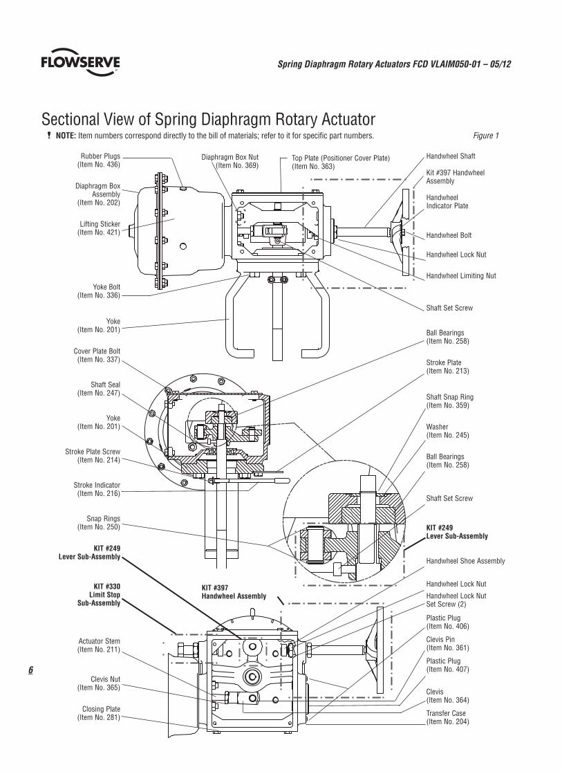
NOTE: Item numbers correspond directly to the bill of materials; refer to it for specific part numbers. Figure 1
Rubber Plugs(Item No. 436)
Diaphragm Box Assembly
(Item No. 202)
Lifting Sticker(Item No. 421)
YokeBolt(Item No. 336)
Yoke(Item No. 201)
Cover Plate Bolt(Item No. 337)
Shaft Seal(Item No. 247)
Yoke(Item No. 201)
Stroke Plate Screw(Item No. 214)
Stroke Indicator(Item No. 216)
Snap Rings(ItemNo.250)
KIT #249Lever Sub-Assembly
KIT #330Limit Stop
Sub-Assembly
Actuator Stem(Item No. 211)
Clevis Nut(ItemNo.365)
Closing Plate(Item No. 281)
Handwheel Shaft
Kit #397 Handwheel Assembly
Handwheel Indicator Plate
Handwheel Bolt
Handwheel Lock Nut
Handwheel Limiting Nut
Shaft Set Screw
Ball Bearings(ItemNo.258)
Stroke Plate(Item No. 213)
Shaft Snap Ring(ItemNo.359)
Washer(ItemNo.245)
Ball Bearings(ItemNo.258)
Shaft Set Screw
KIT #249Lever Sub-Assembly
Handwheel Shoe Assembly
Handwheel Lock Nut
Handwheel Lock Nut Set Screw (2)
Plastic Plug(Item No. 406)
Clevis Pin(Item No. 361)
Plastic Plug(Item No. 407)
Clevis(Item No. 364)
Transfer Case(Item No. 204)
Diaphragm Box Nut (Item No. 369)
Top Plate (Positioner Cover Plate) (Item No. 363)
KIT #397Handwheel Assembly
Sectional View of Spring Diaphragm Rotary Actuator

7
Spring Diaphragm Rotary Actuators FCD VLAIM050-01 – 05/12
flowserve.com
KIT #249 Lever Sub-Assembly KIT #330 Limit Stop Sub-Assembly (Can be used in place of handwheel)
Retainer Ring
Pivot Pin
Roller Bearing
Lever Arm Bearing
Socket Head Bolt
Crank Lever
Limit Stop Bolt
Lock Washer
Limit Stop Bolt Nut
Stroke Stop Shoe
Stroke Stop Shoe Pin
KIT #397 Handwheel Assembly
9
12
11 8
13
10
1
2
3
7
6
4
5
NR 1 & 2Item # Description1 Handwheel2 Indicator Plate3 Handwheel Bolt4 Handwheel Lock Nut5SocketHeadCapscrew(2)6 Handwheel Shaft7 Handwheel Stop Nut
NR 3Item # Description 1 Handwheel 2 Indicator Plate 3 Handwheel Bolt 4 Handwheel Lock Nut5SocketHeadCapscrew(2) 6 Handwheel Shaft 7 Handwheel Stop Nut 8 Shoe Pin 9 Support Pad Shoe10 Base Shoe11 Retainer Shoe12 Ball Bearing13 Retaining ClipWARNING: Do not attach or insert extension bars
into the handwheel, for added torque.
WARNING: The actuator spring is under compression.
1. Position valve vertically
• Itiseasiertochangethediaphragmwiththevalveinthis position.
NOTES:
• Thediaphragmcanbereplacedbyitselfwhilethediaphragm box is mounted to the transfer case, or the whole diaphragm box can be removed and replaced.
• Ifaspringsetchangeisdesired,itisrecommendedthatthe entire diaphragm box be changed out as described in the “changingtheairaction”section.
2. Make sure the limit stop (See kit #330 Limit Stop Sub-Assembly) and lever (See Kit #249 Lever Sub-Assembly) are engaged
• Makesurethelimitstopisengagedwiththelever,sothespring is applying force to the limit stop (or HW).
• Thislimitstopwillholdthediaphragmpistoninplace,andallow you to change the diaphragm without having to relieve the spring.
3. Removethesmalldiaphragmcasenuts(351)andbolts(335)first
WARNING: Use lubricant on the long threads to avoid galling, simplifies spring compression.
• Asasafetyprecaution,removethesmalldiaphragmcasenuts (351)andbolts(335)first,thenremovethethreadcoversoffthe long bolts (334).
4. Apply lubricant to the long bolts (334)
• Itisrecommendedtolubricatethelongspringcompressionbolts (334).
Replacing the Diaphragm, Without Removing the Diaphragm Box

Spring Diaphragm Rotary Actuators FCD VLAIM050-01 – 05/12
8
• Thespring(229)isheldinplacebythelimitstop(SeeKit#330 Limit Stop Sub-Assembly), the diaphragm bolting will have little or no load applied to them.
5. Removetheupperdiaphragmcase(202a)
• Noticeasthecover(202a)isremoved,thatthepiston(227)and diaphragm(225)areheldinpositionbythelimitstop(SeeKit #330 Limit Stop Sub-Assembly) in the transfer case.
• Thispistoncanbemovedbyadjustingthelimitstop.
6. Removethediaphragm(225)fromthepiston(227)
• Peeltheolddiaphragm(225)offthepiston.
• Noticethatthediaphragm(225)isgluedtothepiston(227).
7. Clean the glue from the piston
• Cleantheglueoffthepiston(227).
• CleanthegluefromtheO-ringgrooveintheupperdiaphragm case (202).
8. Applythegluetothediaphragm(225)
• ApplyGluetothenewdiaphragm(225).
• Placethediaphragm(225)ontothepiston(227)androtate it back and forth several times to evenly distribute the glue over the surface of the piston. Next, remove the diaphragm.
• Allowthegluetosetfor2or3minutes.Itwillbecomeverysticky.
• Placediaphragmbackontothepistonandlineuptheboltholes.
9. Install a New O-ring (224) in upper diaphragm case (202a)
• InstallanewO-ringinthediaphragmcover.
• ApplygluetotheO-ringwhileitisintheO-ringgroove.
• GlueusedisScotch-Grip1022.
10. Install the diaphragm case (202a)
• Installtheupperdiaphragmcase(202a).
• Lineuptheboltholes.
11.Installthenuts(350,351)andbolts(334,335)tothediaphragmbox
• Sincethespring(229)isheldincompressionbythelimitstop (See Kit #330 Limit Stop Sub-Assembly), this step should be simple.
• Installthebolting,positioningthe(3)springcompressionbolts (334) 120 degrees apart.
• Itisrecommendedtolubricatethelongspringcompressionbolts (334).
• Readjustlimitstopasneeded.
12. Complete
GENERAL NOTES
• Thediaphragmcanbereplacedbyitselfwhilethediaphragmbox is mounted to the transfer case, or the whole diaphragm box can be removed and replaced.
• Ifaspringsetchangeisdesired,itisrecommendedthatthe entire diaphragm box be changed out as described in the “changingtheairaction”section.
• Itispossibletochangethespringordiaphragmbyusingthe long spring compression bolts to uncompress the spring.
WARNING: Spring is under compression.
1. Position the diaphragm box assembly (202) in a vice
• Removethediaphragmboxassembly(202)asdescribedinthe “Changingairaction”section.
2. Removetheshortdiaphragmnuts(351)andbolts(335)first
• Youcanuseapressontopoftheupperdiaphragmcase(202a) to relieve the spring compression.
• Ifapressisnotavailable,removetheshortdiaphragmnuts(351) and bolts (334) first.
3. Apply a generous amount of lubricant to the (3) long spring compression bolts (334)
• Applyagenerousamountoflubricanttothe(3)longspring compression bolts (334).
• Turneachnut(350),4or5timesandthenalternatetothenext bolt and nut. Gradually separating the upper and lower diaphragm case halves.
4. Remove the upper diaphragm case (202a)
5. Removethediaphragm(225)
6. CompletechangeoutofO-ring(224),diaphragm(225)andspring (229) (if needed)
• Followsteps6to11inthesectiontitled“Replacingthe Diaphragm,WithoutRemovingtheDiaphragmBox”. • Youcannowchangethespringifdesired.
CAUTION: Use caution when compressing the spring.
7. Re-assemble the diaphragm box • Re-assemblyofthediaphragmboxissimplifiedbyusingapress to compress the spring and then installing the diaphragm bolting. • Ifapressisnotavailable,thenfollowsteps1to7inreverse order.
WARNING: Use lubricant on the (3) spring compression bolts (334) prior to compressing spring, to avoid galling.
• Remembertoapplyagenerousamountoflubricanttothelong compression bolts prior to compressing the springs with them.
Replacing the Spring or Diaphragm
Air-to-close Air-to-open
Diaphragm Actuator Orientations
Figure 3

9
Spring Diaphragm Rotary Actuators FCD VLAIM050-01 – 05/12
flowserve.com
NOTE: 1. Item numbers correspond directly to the bill
of materials; refer to it for specific numbers.
2. NR2 guided designs are only used in high cycle applications
3. NR3 guided designs are standard with spring set valves of 1.4 to 2.8 bar (20 to 41 psi)or1.9to3.8bar(28to55psi).
Item # Description
202a Upper Diaphragm Case
203 Lower Diaphragm Case
211 Actuator Stem
224 O-ring Seal
225 Diaphragm
227 Piston Diaphragm
229 Spring
256 NutM8
326 Spring Guide
333 Plastic Tube Protection
334 Bolt M6
335 BoltM6X16
350 NutM6
351 NutM6
435 Sticker
436 Plug Rubber
365 ClevisNut
Kit500 GuidedDiaphragmAssembly
440 Guided Stem
441 Guide Cap
442 Bearing
443 Ret Ring Snap
444 Washer
445 Locknut
Locate the orientation of the pneumatic connection on the center of this hole
KIT #500Guided Diaphragm Assembly(See Notes 2 and 3)442
441
445
227444
440
443
225
Check seal in this area after joining parts
WARNING: Use a press to unload spring, or lubricate the (3) spring compression bolts (334) to unload spring.
Exploded View of Spring Diaphragm Rotary Actuator
Figure 4
256
335
202225
227
224 334
350
435
333
229
326
203
365
211
436
351
256

Spring Diaphragm Rotary Actuators FCD VLAIM050-01 – 05/12
10
Figure 5
Air-to-CloseFail-Open
Air-to-CloseFail-Open
Air-to-CloseFail-Open
Air-to-CloseFail-Open
Air-to-OpenFail-Closed
Air-to-OpenFail-Closed
Air-to-OpenFail-Closed
Air-to-OpenFail-Closed
Shaft Upstream
Left hand mounting (standard)
Right hand mounting (standard)
Right hand mounting (optional)
Shaft Downstream
Mounting Orientations
Spring Diaphragm Rotary Actuator (cover removed)
Figure 4
Left hand mounting (optional)

11
Spring Diaphragm Rotary Actuators FCD VLAIM050-01 – 05/12
flowserve.comFlowserve and Valtek are registered trademarks of Flowserve Corporation.
Troubleshooting Rotary ActuatorsFailure Probable Cause Corrective Action
Actuator operates, shaft does not rotate
1. Broken actuator stem 1. Replace actuator stem
2.Brokenclevis(364)ormissingsnaprings(250)thatallowed pin to move
2. Replace clevis if broken, and make sure the snap rings are snugly placed into the snap ring groove
3. Torn or broken diaphragm 3. Replace diaphragm
High air consumption or leakage
1. Leaks in the air supply or instrument signal system 1. Tighten connections and replace any leaking lines
2. Malfunctioning positioner 2. Refer to positioner’s maintenance instructions
3. Broken diaphragm or 0-ring seal 3. Replace diaphragm or 0-ring seal

flowserve.com
Flowserve Corporation has established industry leadership in the design and manufacture of its products. When properly selected, this Flowserve product is designed to perform its intended function safely during its useful life. However, the purchaser or user of Flowserve products should be aware that Flowserve products might be used in numerous applications under a wide variety of industrial service conditions. Although Flowserve can (and often does) provide general guidelines, it cannot provide specific data and warnings for all possible applications. The pur-chaser/user must therefore assume the ultimate responsibility for the proper sizing and selection, installation, operation, and maintenance of Flowserve products. The purchaser/user should read and understand the Installation Operation Maintenance (IOM) instructions included with the product, and train its employees and contractors in the safe use of Flowserve products in connection with the specific application.
While the information and specifications contained in this literature are believed to be accurate, they are supplied for informative purposes only and should not be considered certified or as a guarantee of satisfactory results by reliance thereon. Nothing contained herein is to be construed as a warranty or guarantee, express or implied, regarding any matter with respect to this product. Because Flowserve is continually improving and upgrading its product design, the specifications, dimensions and information contained herein are subject to change without notice. Should any question arise concerning these provisions, the purchaser/user should contact Flowserve Corporation at any one of its worldwide operations or offices.
© 2009 Flowserve Corporation, Irving, Texas, USA. Flowserve is a registered trademark of Flowserve Corporation.
United StatesFlowserve Corp.Flow ControlFlowserve Valtek Control Products1350N.Mt.SpringsParkwaySpringville, UT 84663 USAPhone: 1 801 489 8611Fax: 1 801 489 3719
Regional Headquarters1350N.Mt.SpringsPrkwy.Springville, UT 84663Phone: 801 489 8611Fax: 801 489 3719
12 Tuas Avenue 20Republic of Singapore 638824Phone:658623332Fax:658624940
12,av.duQuébec,B.P.64591965,CourtaboeufCedex,FrancePhone:33160923251Fax: 33 1 60 92 32 99
Quick Response Centers5114RailroadStreetDeerPark,TX77536USAPhone:2814799500Fax:2814798511
104 Chelsea ParkwayBoothwyn, PA 19061 USAPhone: 610 497 8600Fax: 610 497 6680
1300 Parkway View DrivePittsburgh,PA15205USAPhone: 412 787 8803Fax: 412 787 1944
FCDVLAIM050-01PrintedinUSA.
VALTECNO.185064
To find your local Flowserve representative or for more information about Flowserve Corporation, visit www.flowserve.com.


