Download - Unit I - Introduction to Eng Drawing
MENG 1008MENG 1008
Engineering Drawing
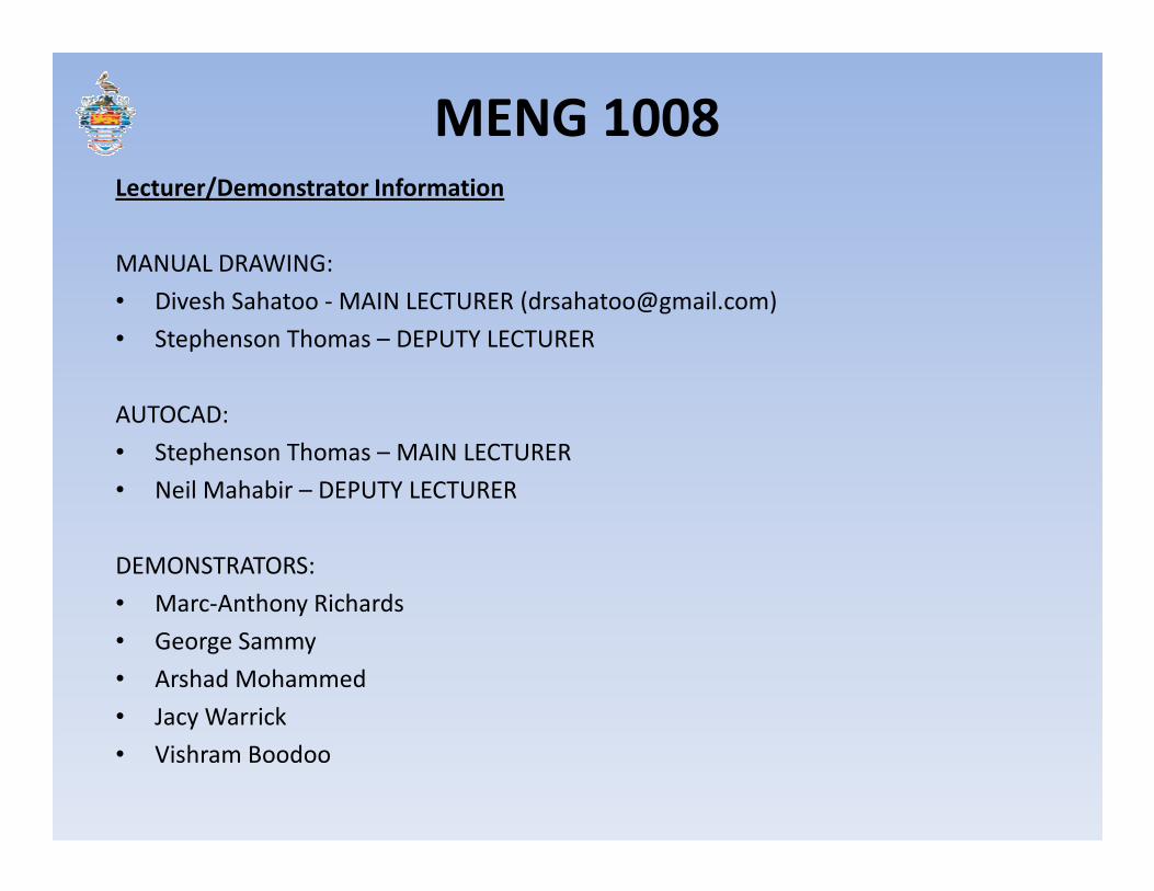
MENG 1008Lecturer/Demonstrator Information
MANUAL DRAWING:
• Divesh Sahatoo - MAIN LECTURER ([email protected])
• Stephenson Thomas – DEPUTY LECTURER
AUTOCAD:
• Stephenson Thomas – MAIN LECTURER• Stephenson Thomas – MAIN LECTURER
• Neil Mahabir – DEPUTY LECTURER
DEMONSTRATORS:
• Marc-Anthony Richards
• George Sammy
• Arshad Mohammed
• Jacy Warrick
• Vishram Boodoo
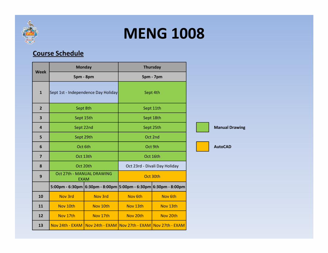
MENG 1008Course Schedule
WeekMonday Thursday
5pm - 8pm 5pm - 7pm
1 Sept 1st - Independence Day Holiday Sept 4th
2 Sept 8th Sept 11th
3 Sept 15th Sept 18th
4 Sept 22nd Sept 25th Manual Drawing4 Sept 22nd Sept 25th Manual Drawing
5 Sept 29th Oct 2nd
6 Oct 6th Oct 9th AutoCAD
7 Oct 13th Oct 16th
8 Oct 20th Oct 23rd - Divali Day Holiday
9Oct 27th - MANUAL DRAWING
EXAMOct 30th
5:00pm - 6:30pm 6:30pm - 8:00pm 5:00pm - 6:30pm 6:30pm - 8:00pm
10 Nov 3rd Nov 3rd Nov 6th Nov 6th
11 Nov 10th Nov 10th Nov 13th Nov 13th
12 Nov 17th Nov 17th Nov 20th Nov 20th
13 Nov 24th - EXAM Nov 24th - EXAM Nov 27th - EXAM Nov 27th - EXAM

MENG 1008
UNIT – I: INTRODUCTION TO ENGINEERING DRAWING
Principles of Engineering Graphics and their Significance –Drawing Instruments and their Use – Conventions in Drawing – Lettering – Drawing Standards, Engineering Scales, Simple Geometries.
UNIT – II: DRAWING OF PROJECTIONS
Principles of Orthographic Projections – Conventions – First and Third Angle Projections, Projections of Points and Lines inclined to both planes, True lengths.
MANUAL DRAWING COMPONENTS
UNIT – V: ISOMETRIC PROJECTIONS
Principles of Isometric Projection – Isometric Scale –Isometric Views– Conventions – Isometric Views of Lines, Plane Figures, Simple and Compound Solids – Isometric Projection of objects having non- isometric lines. Isometric Projection of Spherical Parts.
UNIT – VI: CONVERSION OF ISOMETRIC AND ORTHOGRAPHIC VIEWS
Conversion of orthographic views into isometric views and Conversion of Isometric Views to Orthographic Views
inclined to both planes, True lengths.
UNIT – III: PROJECTIONS OF PLANES and SOLIDS
Projections of regular Planes, auxiliary planes and Auxiliary projection inclined to both planes. Projections of Regular Solids inclined to both planes – Auxiliary Views. Sections and Sectional views of Right Regular Solids – Prism, Cylinder, Pyramid, Cone – Auxiliary views.
UNIT IV: DEVELOPMENT AND INTERPENETRATION OF SOLIDS
Development of Surfaces of Right Regular Solids – Prisms, Cylinder, Pyramid Cone and their parts. Interpenetration of Right Regular Solids – Intersection of Cylinder Vs Cylinder, Cylinder Vs Prism, Cylinder Vs Cone.
Conversion of Isometric Views to Orthographic Views
UNIT VII: PLANE GEOMETRICAL DRAWING
Geometrical Constructions and Curves Used in Engineering Practice - a) Conic Sections including the Rectangular Hyperbola – General method only, b) Cycloid, Epicycloid and Hypocycloid, c) Involute, d) Helices; Freehand Sketching Techniques.
UNIT VIII : PERSPECTIVE PROJECTIONS
Perspective Views: Points, Lines, Plane Figures and Simple Solids, Vanishing Point Methods (General Method only).

MENG 1008
Week 1
• Introduction to AutoCAD: What is AutoCAD?
• Drawing environments( Graphics area, menu browser button, command line, status bar, layout tabs)
• Starting a New Drawing (templates)
• Naming a drawing
• Drawing Units
• Drawing Limits
• Coordinate system (Rectangular and Polar)
• Direct Distance Entry
• Lines , rectangles, circles, arcs
• Layers
AUTOCAD COMPONENTS
• Layers
• Osnap
• Editing features : erase , move, copy , offset, array , rotate, trim , extend, break, chamfer, fillet, mirror, polar tracking
Week 2
• Dimensioning : Dimension elements, Types of dimensioning
• Texts: Single line and Multiline texts
• Polyline, pedit, ellipse, polygon , point
• Hatching
• Plotting: Paper Space and Model Space
Week 3
• Review
MENG 1008
• Engineering drawing is its own language.
Consists of symbols and conventions which allow those who understand it to document
and communicate effectively regardless of what language they speak.
• Used to effectively plan.
Engineering jobs/projects require proper planning to be safe and successful. Engineering
WHY ENGINEERING DRAWING?
drawing conventions allow projects to be documented and hence thoroughly reviewed
before being executed.
This course is intended to introduce students to the fundamental rules, conventions, and
procedures used for creating and interpreting engineering drawings. Through the use of
several worked examples and practice exercises, students will have the opportunity to
develop their own engineering drawing skills using both manual techniques and computer
aided design (CAD) software.

MENG 1008
Several standards exist which outline the proper and accepted methods for creating,
communicating and documenting drawings.
A standard is “something established for use as a rule or basis of comparison in measuring or
judging capacity, quantity, content, extent, value, quality, etc.”
Drawing standard organizations:
DRAWING STANDARDS
Drawing standard organizations:
• ISO - International Standards Organization
• ANSI - American National Standards Institute
• TTBS - TTS Trinidad and Tobago Bureau of Standards

MENG 1008DRAWING STANDARDS
STANDARD NUMBER STANDARD TITLE
TTBS/ISO 3040 2008 Technical Drawings – Dimensioning and Tolerancing – cones
TTS/ISO 128-1 2008 Technical Drawings – General Principles – Part 1: Introduction and Index
TTS/ISO 129-1 2008 Technical Drawings – Indication of Dimensions and Tolerances – Part 1 – General Principles
TTS/ISO 406 2008 Technical Drawings – Tolerancing of Linear and Angular Dimensions
TTS/ISO 5457 2008 Technical Product Documentation – Sizes and Layout of Drawing Sheets
TTS/ISO 7083 2008 Technical Drawings – Symbols for Geometrical Tolerancing o Proportions and Dimensions
TTS/ISO 6433 2008 Technical Drawings – Item ReferencesTTS/ISO 6433 2008 Technical Drawings – Item References
TTS/ISO 5455 2008 Technical Drawings – Items Scales
TTS/ISO 10209-1 2008 Technical Product Documentation – Vocabulary – Part 1 – Terms Relating to Technical Drawings:
General and Types of Drawings
TTS 31 85 401 1988 Technical Drawings – Dimensioning – General Principles, Definitions, Methods of Execution and
Special Indications
TTS 31 85 002-1 1988 Technical Drawings – Lettering: Currently Used Characters
ANSI Y14.1 – 1980 (R1987) Drawing Sheet Size and Format
ANSI Y14.2M – 1979 (R1987) Line Conventions and Lettering
ANSI Y14.3 – 1975 (R1987) Multiview and Sectional View Drawings
ANSI Y 14.5 M – 1994 Dimensioning and Tolerancing

MENG 1008
• T – square.
• 30° and 45 ° set squares (large – 360mm).
• Metric ruler.
• Large Protractor.
• Spring-bow compass.
• French curves.
• Circle template.
DRAWING TOOLS
• Circle template.
• Paper – A2 size (420mm x 594mm).
• Pencils:– 2H: Used for drawing guidelines.
– 2B: Used for bordering, darkening and writing.
MENG 1008
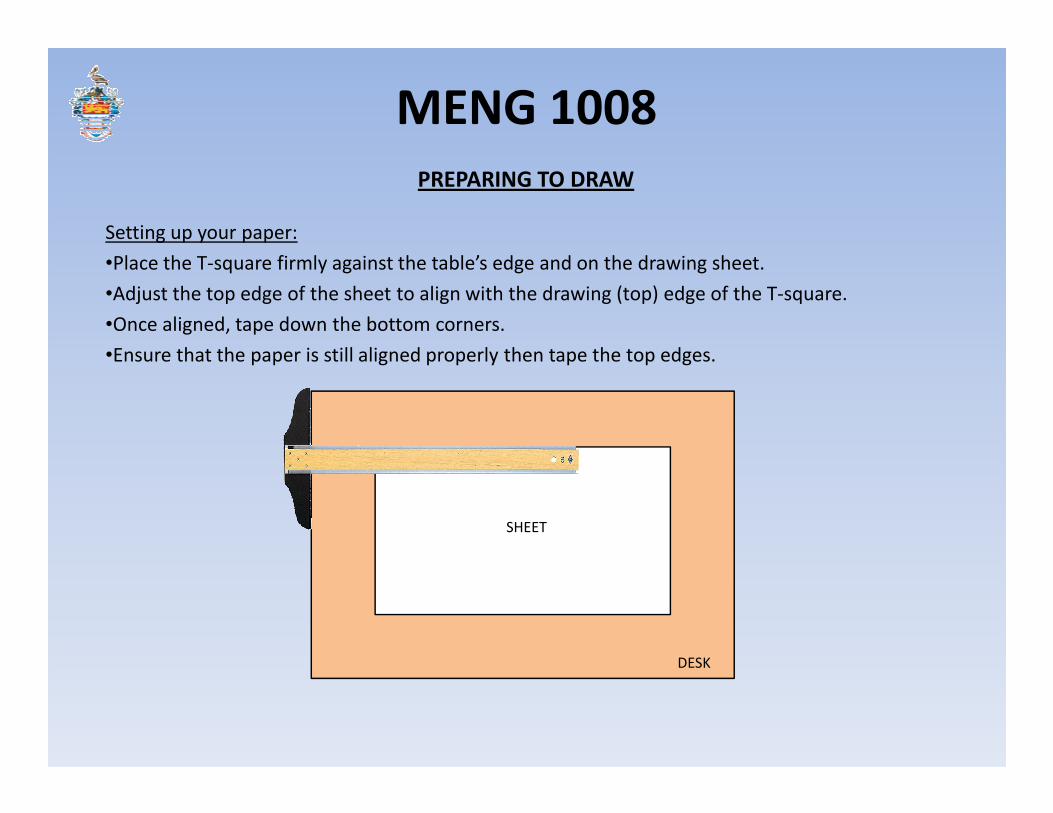
Setting up your paper:
•Place the T-square firmly against the table’s edge and on the drawing sheet.
•Adjust the top edge of the sheet to align with the drawing (top) edge of the T-square.
•Once aligned, tape down the bottom corners.
•Ensure that the paper is still aligned properly then tape the top edges.
PREPARING TO DRAW
SHEET
DESK

MENG 1008
Bordering:
Before beginning to draw, your sheet should be bordered. All drawing is to take place within
this border.
•Using your ruler or set square, measure and mark a distance of 10mm from each of the 4
sides of the sheet.
• Using your T-Square and set squares draw light (2H) lines through these points which are
parallel to the each immediate side of the sheet.
PREPARING TO DRAW
parallel to the each immediate side of the sheet.
•Once this is complete, darken the border using your 2B pencil.

MENG 1008
Bordering:
PREPARING TO DRAW
MENG 1008
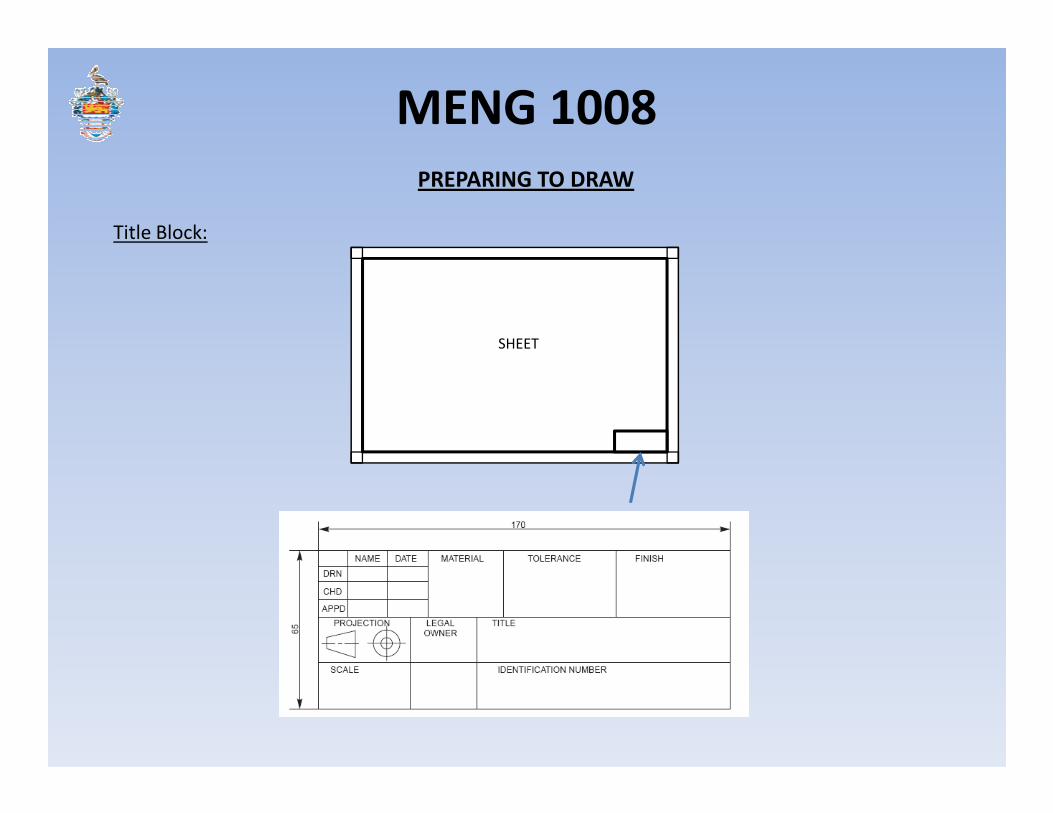
Title Block:
PREPARING TO DRAW
SHEET
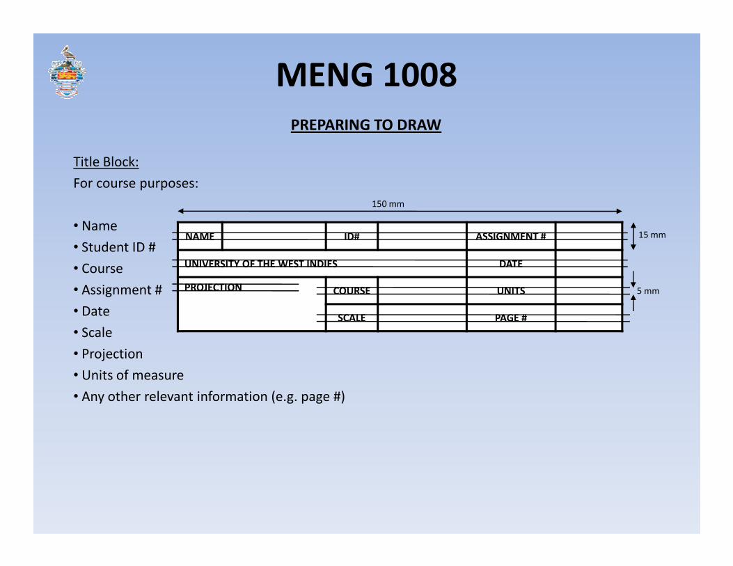
MENG 1008
Title Block:
For course purposes:
• Name
• Student ID #
• Course
• Assignment #
PREPARING TO DRAW
NAME ID# ASSIGNMENT #
UNIVERSITY OF THE WEST INDIES DATE
PROJECTION
15 mm
150 mm
• Assignment #
• Date
• Scale
• Projection
• Units of measure
• Any other relevant information (e.g. page #)
PROJECTION COURSE UNITS
SCALE PAGE #
5 mm

MENG 1008
Lettering:
Using 2B or HB pencil.
PREPARING TO DRAW

MENG 1008
Lettering:
Using 2B or HB pencil. 5 mm height.
PREPARING TO DRAW
MENG 1008
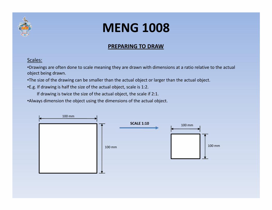
Scales:
•Drawings are often done to scale meaning they are drawn with dimensions at a ratio relative to the actual
object being drawn.
•The size of the drawing can be smaller than the actual object or larger than the actual object.
•E.g. If drawing is half the size of the actual object, scale is 1:2.
If drawing is twice the size of the actual object, the scale if 2:1.
•Always dimension the object using the dimensions of the actual object.
PREPARING TO DRAW
100 mm
100 mm
SCALE 1:10 100 mm
100 mm
MENG 1008
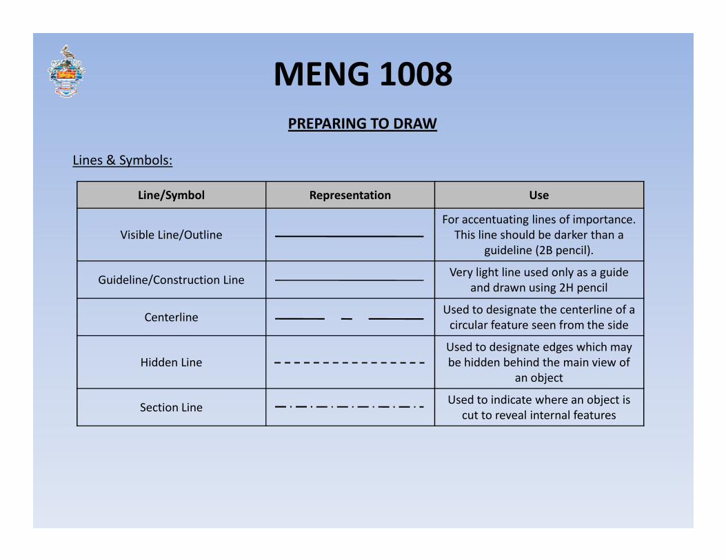
Lines & Symbols:
PREPARING TO DRAW
Line/Symbol Representation Use
Visible Line/Outline
For accentuating lines of importance.
This line should be darker than a
guideline (2B pencil).
Guideline/Construction LineVery light line used only as a guide
and drawn using 2H pencilGuideline/Construction Line
and drawn using 2H pencil
CenterlineUsed to designate the centerline of a
circular feature seen from the side
Hidden Line
Used to designate edges which may
be hidden behind the main view of
an object
Section LineUsed to indicate where an object is
cut to reveal internal features

MENG 1008
Lines & Symbols:
PREPARING TO DRAW
Line/Symbol Representation Use
Dimension Line (a)Runs parallel to and is the same
length of the line being dimensioned
Extension Line (b)
Two short lines (typically 8mm long)
which are perpendicular to but not
touching the line being dimensioned
(a)
(b) (b)
touching the line being dimensioned
Diameter
Used to dimension the diameter of a
circle. The arrowhead always points
toward the center of the circle.
RadiusUsed to dimension the radius of a
circle
Center pointUsed to designate the center of an
object when seen as a circle
Ø10
R10
MENG 1008
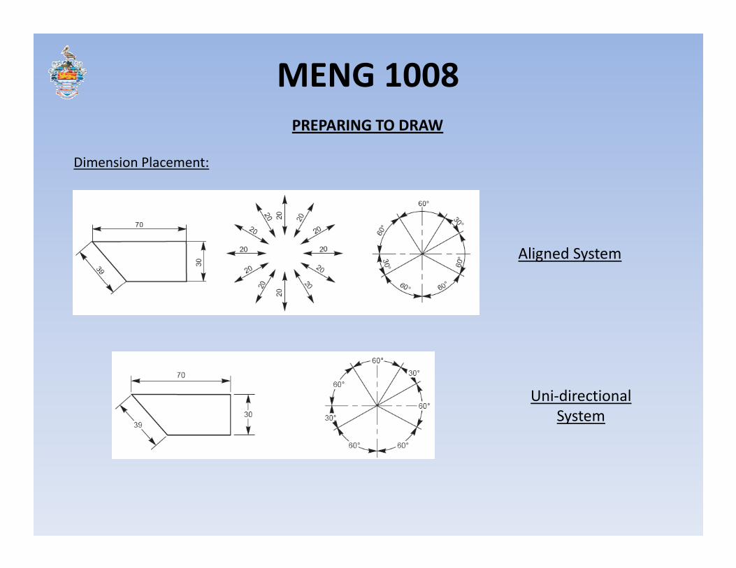
Dimension Placement:
PREPARING TO DRAW
Aligned System
Uni-directional
System

MENG 1008
Dimensioning Arrowheads:
PREPARING TO DRAW
3
1

MENG 1008
Units:
•Imperial System – inches
•Metric System – millimeters
PREPARING TO DRAW

MENG 1008
DRAWING SIMPLE GEOMETRY
Horizontal Straight Line
•Using T-square, draw light horizontal line using 2H pencil.
•Mark off the length of line desired. Measure using ruler or set square.
•Darken desired length using 2B pencil.
•Dimension if required.100 mm
Vertical Straight Line
•Place T-square against left/right edge of T-square.
•Place shorter edge of set square against top edge of T-square.
•Draw light vertical line using 2H pencil.
•Darken desired length using 2B pencil.
•Dimension if required.100 mm

MENG 1008
Straight Line at an Angle
•Using T-square, draw light horizontal line using 2H pencil.
•Mark off the length of horizontal line desired. Measure using ruler or set square.
•Darken desired length using 2B pencil.
•Using protractor (or set square depending on the angle), mark desired angle then draw light
guideline through mark.
DRAWING SIMPLE GEOMETRY
guideline through mark.
•Measure and darken length of angled line desired.
•Dimension if required.
Circle
•Using ruler or set square and compass, open compass to desired radius.
•Place metal tip of compass on paper where desired and draw circle.
•Dimension if required.
100 mm
30°
MENG 1008
Download Link:
https://drive.google.com/file/d/0B-eFyzDsfAnWenE4OFZiS05kSnM/edit?usp=sharing


