Download - TREADMILL SERVICE MANUAL
TREADMILL SERVICE MANUAL
T801/T802/T803
T81dmilt
Customer Support Services
SERVICE MANUAL
HS Consumer Treadmill INTRODUCTION
Section 2 2
HOW TO USE SERVICE MANUAL AND CONTACT CUSTOMER SUPPORT SERVICES
This service manual is applicable to Treadmill T801, T802, T803. Note: Information represents typical configuration
and may differ slightly from actual equipment. The Service Manual provides recommendations of safe and efficient
approaches to various situations. This manual is separated into six sections.
INTRODUCTION
TABLE OF CONTENTS
Section Ⅰ
� TROUBLESHOOTING GUIDE
Section Ⅱ
� OPERATING CONSOLE
Section Ⅲ
� “How To…” SERVICE AND REPAIR GUIDE
Section Ⅳ
� ELECTRONIC OVERVIEW
� WIRING BLOCK DIAGRAM
� WIRING DIAGRAM AND PART LIST
Section Ⅴ
� PARTS IDENTIFICATION
Section Ⅵ
� MISCELLANEOUS INFORMATION
Refer to TABLE OF CONTENTS for section topics.
When an operation problem occurs, refer to troubleshooting guide and diagnostic mode to isolate cause. When
applicable, guides are listed by problem symptom followed with suggestions of probable cause(s).
Once source of problem is identified, consult” How To…” guides for recommended repair procedures. “How To…”
sub-sections are organized by replacement part or assembly name. For convenience, sub-section lists recommended
“Tools Required” to complete specific function. Refer to PARTS IDENTIFICATION to identify proper name and number
of part to order for repair of equipment.
A reproducible FAX order claim form is given in COMMUNICATING BY TELEFACSIMILE for convenient ordering of
service parts.
To order, contact HS Customer Support Services.
Via FAX – 24 hrs/day, 7days/week.
Via telephone – Monday to Friday from 8:30 AM to 5:30 PM (GMT+8)
Via post – At address cited.
To speed HS response to your needs, please provide the following information.
1. Model number
2. Serial number
3. Symptom of problem
4. Part name and number to order (if known)
Before installing parts, review “How To…” and follow step by step procedures recommended to install parts safely and
efficiently. If you have questions or comments please telephone, FAX or write us. We are:
Healthstream Taiwan Inc. – CUSTOMER SUPPORT SERVICES
16-3, Zichiang 1st Road
Jhongli, Taoyuan 32063 Taiwan R.O.C.
HS Consumer Treadmill TABLE OF CONTENTS
SECTION I TROUBLESHOOTING GUIDE PAGE
MCB…………….…………..…………………………………….……………………………………………… 2
CONSOLE……………..…………………………………………………………………………..…………….. 8
SECTION II OPERATING CONSOLE
T801 CONSOLE…..……………………………….……………………...…………………………………….. 2
T802 CONSOLE……………………………………………..………………………………………………….. 7
T803 CONSOLE…………………………………………………………………………………………………. 13
SETUP AND DIAGNOSTIC MODE…………………………………………………………………….…. 19
SECTION III HOW TO…REPLACE
RUNNING BELT AND DECK……….…………..………………………………………………………………. 2
ADJUST RUNNING BELT TRACKING………………………………………………………………………... 4
ADJUST RUNNING BELT TENSION………………………………………………………………………….. 5
MOTOR DRIVE BELT…………………………………………………………………………………………… 6
DRIVE MOTOR………………………………………………………………………………………………….. 7
FRONT ROLLER………………………………………………………………………………………………… 8
REAR ROLLER………………………………………………………………………………………………….. 9
DECK CUSHION ………………………………………………………………………………………………... 10
INCLINE MOTOR………………………………………………………………………………………………... 12
MOTOR CONTROLLER………………………………………………………………………………………… 14
MAIN FRAME MOVING WHEEL………………………………………………………………………………. 15
SECTION IV ELECTRONIC OVERVIEW AND WIRING DIAGRAMS
T801 CONSOLE……………………………………………….………………………………….…………….. 2
T802 CONSOLE…………………………………………………………………………………………………. 4
T803 CONSOLE…………………………………………………………………………………………………. 6
MOTOR CONTROLLER PCB…………………………………………………………………………..……… 8
T801 BLOCK DIAGRAM….…………………………….………………………………………………………. 10
T802 BLOCK DIAGRAM………………………………………………..………………………………………. 11
T803 BLOCK DIAGRAM………………………………………………..………………………………………. 12
T801 WIRING DIAGRAM AND PART LIST (CE VERSION)………...………………………………...……. 13
T802 WIRING DIAGRAM AND PART LIST (CE VERSION)………...………………………………...……. 15
T802 WIRING DIAGRAM AND PART LIST (CE VERSION)………...………………………………...……. 17
HS Consumer Treadmill TABLE OF CONTENTS - Continued
SECTION V PARTS IDENTIFICATION
T801LA/EXPLODED DRAWING.….…………………………………………….…………………………….. 2
T801LA/PART LIST…………………………………………………………………………..…………………. 7
T802LA/EXPLODED DRAWING………………………………………………………………………………. 11
T802LA/PART LIST……………………………………………………………………………………………… 16
T803LA/EXPLODED DRAWING………………………………………………………………………………. 21
T803LA/PART LIST……………………………………………………………………………………………… 26
SECTION VI MISCELLANEOUS INFORMATION
PREVENTIVE MAINTENANCE………………………………………………………………………………... 2
UNPACKAGING INSTRUCTIONS…………………………………………………………………………….. 3
T802/T803/INSTALLATION INSTRUCTIONS……………………………………………………………….. 4
T801/INSTALLATION INSTRUCTIONS………………………………………………………………………. 8
LIFE FAX……….…………..…………………………………………………………………………………….. 12
NOTES……………………………………………………………………………………………………………. 13

HS Consumer Treadmill
Section 1 1
Section I
Section I
SECTION I
TROUBLESHOOTING GUIDE
HS Consumer Treadmill TROUBLESHOOTING GUIDE
Section 1 2
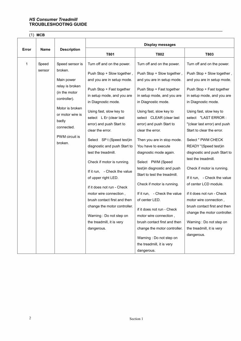
(1) MCB
Error Name Description
Display messages
T801 T802 T803
1 Speed
sensor
Speed sensor is
broken.
Main power
relay is broken
(in the motor
controller).
Motor is broken
or motor wire is
badly
connected.
PWM circuit is
broken.
Turn off and on the power.
Push Stop + Slow together ,
and you are in setup mode.
Push Stop + Fast together
in setup mode, and you are
in Diagnostic mode.
Using fast, slow key to
select L Er (clear last
error) and push Start to
clear the error.
Select SP t (Speed test)in
disgnostic and push Start to
test the treadmill.
Check if motor is running.
If it run, - Check the value
of upper right LED.
if it does not run - Check
motor wire connection ,
brush contact first and then
change the motor controller.
Warning : Do not step on
the treadmill, it is very
dangerous.
Turn off and on the power.
Push Stop + Slow together ,
and you are in setup mode.
Push Stop + Fast together
in setup mode, and you are
in Diagnostic mode.
Using fast, slow key to
select CLEAR (clear last
error) and push Start to
clear the error.
Then you are in stop mode.
You have to execute
diagnostic mode again.
Select PWM (Speed
test)in disgnostic and push
Start to test the treadmill.
Check if motor is running.
If it run, - Check the value
of center LED.
if it does not run - Check
motor wire connection ,
brush contact first and then
change the motor controller.
Warning : Do not step on
the treadmill, it is very
dangerous.
Turn off and on the power.
Push Stop + Slow together ,
and you are in setup mode.
Push Stop + Fast together
in setup mode, and you are
in Diagnostic mode.
Using fast, slow key to
select "LAST ERROR :
"(clear last error) and push
Start to clear the error.
Select " PWM CHECK
READY "(Speed test)in
disgnostic and push Start to
test the treadmill.
Check if motor is running.
If it run, - Check the value
of center LCD module.
if it does not run - Check
motor wire connection ,
brush contact first and then
change the motor controller.
Warning : Do not step on
the treadmill, it is very
dangerous.
HS Consumer Treadmill
Section 1 3
Error Name Description
Display messages
T801 T802 T803
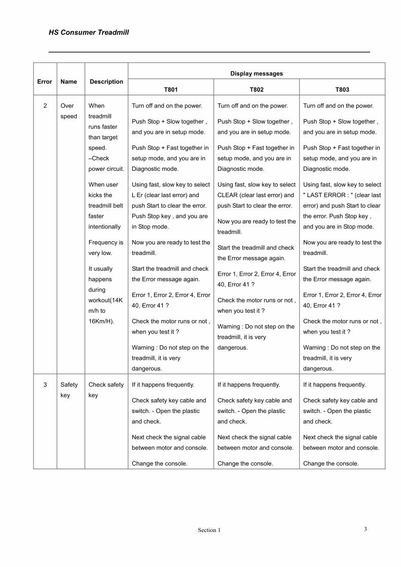
2 Over
speed
When
treadmill
runs faster
than target
speed.
–Check
power circuit.
When user
kicks the
treadmill belt
faster
intentionally
Frequency is
very low.
It usually
happens
during
workout(14K
m/h to
16Km/H).
Turn off and on the power.
Push Stop + Slow together ,
and you are in setup mode.
Push Stop + Fast together in
setup mode, and you are in
Diagnostic mode.
Using fast, slow key to select
L Er (clear last error) and
push Start to clear the error.
Push Stop key , and you are
in Stop mode.
Now you are ready to test the
treadmill.
Start the treadmill and check
the Error message again.
Error 1, Error 2, Error 4, Error
40, Error 41 ?
Check the motor runs or not ,
when you test it ?
Warning : Do not step on the
treadmill, it is very
dangerous.
Turn off and on the power.
Push Stop + Slow together ,
and you are in setup mode.
Push Stop + Fast together in
setup mode, and you are in
Diagnostic mode.
Using fast, slow key to select
CLEAR (clear last error) and
push Start to clear the error.
Now you are ready to test the
treadmill.
Start the treadmill and check
the Error message again.
Error 1, Error 2, Error 4, Error
40, Error 41 ?
Check the motor runs or not ,
when you test it ?
Warning : Do not step on the
treadmill, it is very
dangerous.
Turn off and on the power.
Push Stop + Slow together ,
and you are in setup mode.
Push Stop + Fast together in
setup mode, and you are in
Diagnostic mode.
Using fast, slow key to select
" LAST ERROR : " (clear last
error) and push Start to clear
the error. Push Stop key ,
and you are in Stop mode.
Now you are ready to test the
treadmill.
Start the treadmill and check
the Error message again.
Error 1, Error 2, Error 4, Error
40, Error 41 ?
Check the motor runs or not ,
when you test it ?
Warning : Do not step on the
treadmill, it is very
dangerous.
3 Safety
key
Check safety
key
If it happens frequently.
Check safety key cable and
switch. - Open the plastic
and check.
Next check the signal cable
between motor and console.
Change the console.
If it happens frequently.
Check safety key cable and
switch. - Open the plastic
and check.
Next check the signal cable
between motor and console.
Change the console.
If it happens frequently.
Check safety key cable and
switch. - Open the plastic
and check.
Next check the signal cable
between motor and console.
Change the console.
HS Consumer Treadmill TROUBLESHOOTING GUIDE
Section 1 4
Error Name Description
Display messages
T801 T802 T803
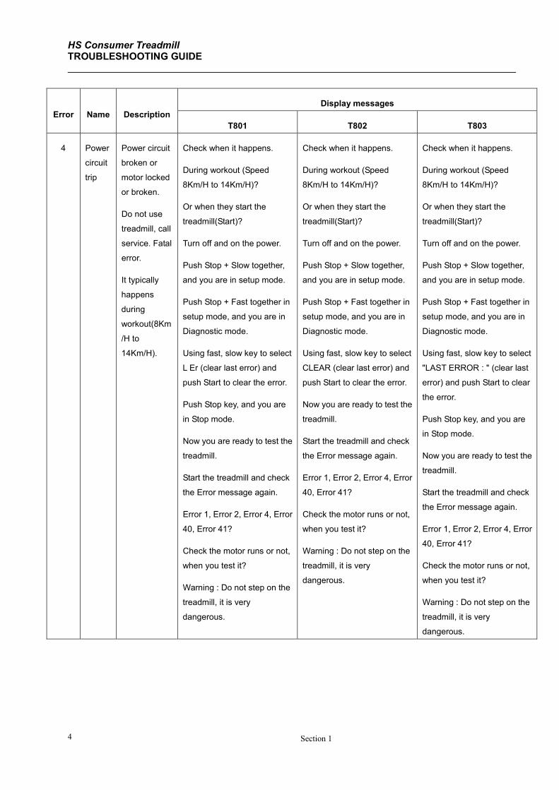
4 Power
circuit
trip
Power circuit
broken or
motor locked
or broken.
Do not use
treadmill, call
service. Fatal
error.
It typically
happens
during
workout(8Km
/H to
14Km/H).
Check when it happens.
During workout (Speed
8Km/H to 14Km/H)?
Or when they start the
treadmill(Start)?
Turn off and on the power.
Push Stop + Slow together,
and you are in setup mode.
Push Stop + Fast together in
setup mode, and you are in
Diagnostic mode.
Using fast, slow key to select
L Er (clear last error) and
push Start to clear the error.
Push Stop key, and you are
in Stop mode.
Now you are ready to test the
treadmill.
Start the treadmill and check
the Error message again.
Error 1, Error 2, Error 4, Error
40, Error 41?
Check the motor runs or not,
when you test it?
Warning : Do not step on the
treadmill, it is very
dangerous.
Check when it happens.
During workout (Speed
8Km/H to 14Km/H)?
Or when they start the
treadmill(Start)?
Turn off and on the power.
Push Stop + Slow together,
and you are in setup mode.
Push Stop + Fast together in
setup mode, and you are in
Diagnostic mode.
Using fast, slow key to select
CLEAR (clear last error) and
push Start to clear the error.
Now you are ready to test the
treadmill.
Start the treadmill and check
the Error message again.
Error 1, Error 2, Error 4, Error
40, Error 41?
Check the motor runs or not,
when you test it?
Warning : Do not step on the
treadmill, it is very
dangerous.
Check when it happens.
During workout (Speed
8Km/H to 14Km/H)?
Or when they start the
treadmill(Start)?
Turn off and on the power.
Push Stop + Slow together,
and you are in setup mode.
Push Stop + Fast together in
setup mode, and you are in
Diagnostic mode.
Using fast, slow key to select
"LAST ERROR : " (clear last
error) and push Start to clear
the error.
Push Stop key, and you are
in Stop mode.
Now you are ready to test the
treadmill.
Start the treadmill and check
the Error message again.
Error 1, Error 2, Error 4, Error
40, Error 41?
Check the motor runs or not,
when you test it?
Warning : Do not step on the
treadmill, it is very
dangerous.
HS Consumer Treadmill TROUBLESHOOTING GUIDE - Continued
Section 1 5
Error Name Description
Display messages
T801 T802 T803
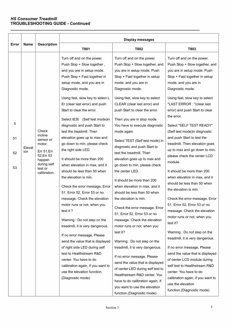
5
51
52
53
Elevation
Check
incline
sensor or
motor.
Err 51,Err
52,Err 53
happen
during self
test or
calibration.
Turn off and on the power.
Push Stop + Slow together ,
and you are in setup mode.
Push Stop + Fast together in
setup mode, and you are in
Diagnostic mode.
Using fast, slow key to select L
Er (clear last error) and push
Start to clear the error.
Select tESt (Self test mode)in
disgnostic and push Start to
test the treadmill. Then
elevation goes up to max and
go down to min, please check
the right side LED.
It should be more than 200
when elevation in max, and it
should be less than 50 when
the elevation is min.
Check the error message. Error
51, Error 52, Error 53 or no
message. Check the elevation
motor runs or not, when you
test it ?
Warning : Do not step on the
treadmill, it is very dangerous.
If no error message, Please
send the value that is displayed
of right side LED during self
test to Healthstream R&D
center. You have to do
calibration again, if you want to
use the elevation function.
(Diagnostic mode)
Turn off and on the power.
Push Stop + Slow together, and
you are in setup mode. Push
Stop + Fast together in setup
mode, and you are in
Diagnostic mode.
Using fast, slow key to select
CLEAR (clear last error) and
push Start to clear the error.
Then you are in stop mode.
You have to execute diagnostic
mode again.
Select TEST (Self test mode) in
disgnostic and push Start to
test the treadmill. Then
elevation goes up to max and
go down to min, please check
the center LED.
It should be more than 200
when elevation in max, and it
should be less than 50 when
the elevation is min.
Check the error message. Error
51, Error 52, Error 53 or no
message. Check the elevation
motor runs or not, when you
test it?
Warning : Do not step on the
treadmill, it is very dangerous.
If no error message, Please
send the value that is displayed
of center LED during self test to
Healthstream R&D center. You
have to do calibration again, if
you want to use the elevation
function.(Diagnostic mode)
Turn off and on the power.
Push Stop + Slow together, and
you are in setup mode. Push
Stop + Fast together in setup
mode, and you are in
Diagnostic mode.
Using fast, slow key to select
"LAST ERROR : "(clear last
error) and push Start to clear
the error.
Select "SELF TEST READY"
(Self test mode)in disgnostic
and push Start to test the
treadmill. Then elevation goes
up to max and go down to min,
please check the center LCD
module.
It should be more than 200
when elevation in max, and it
should be less than 50 when
the elevation is min.
Check the error message. Error
51, Error 52, Error 53 or no
message. Check the elevation
motor runs or not, when you
test it?
Warning : Do not step on the
treadmill, it is very dangerous.
If no error message, Please
send the value that is displayed
of center LCD module during
self test to Healthstream R&D
center. You have to do
calibration again, if you want to
use the elevation
function.(Diagnostic mode)
HS Consumer Treadmill TROUBLESHOOTING GUIDE
Section 1 6
Error Name Description
Display messages
T801 T802 T803
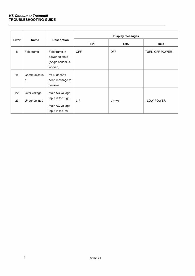
8 Fold frame Fold frame in
power on state
(Angle sensor is
worked)
OFF OFF TURN OFF POWER
11 Communicatio
n
MCB doesn’t
send message to
console
22
23
Over voltage
Under voltage
Main AC voltage
input is too high
Main AC voltage
input is too low
L-P
L PWR
- LOW POWER
HS Consumer Treadmill TROUBLESHOOTING GUIDE - Continued
Section 1 7
Section I
Error Name Description
Display messages
T801 T802 T803
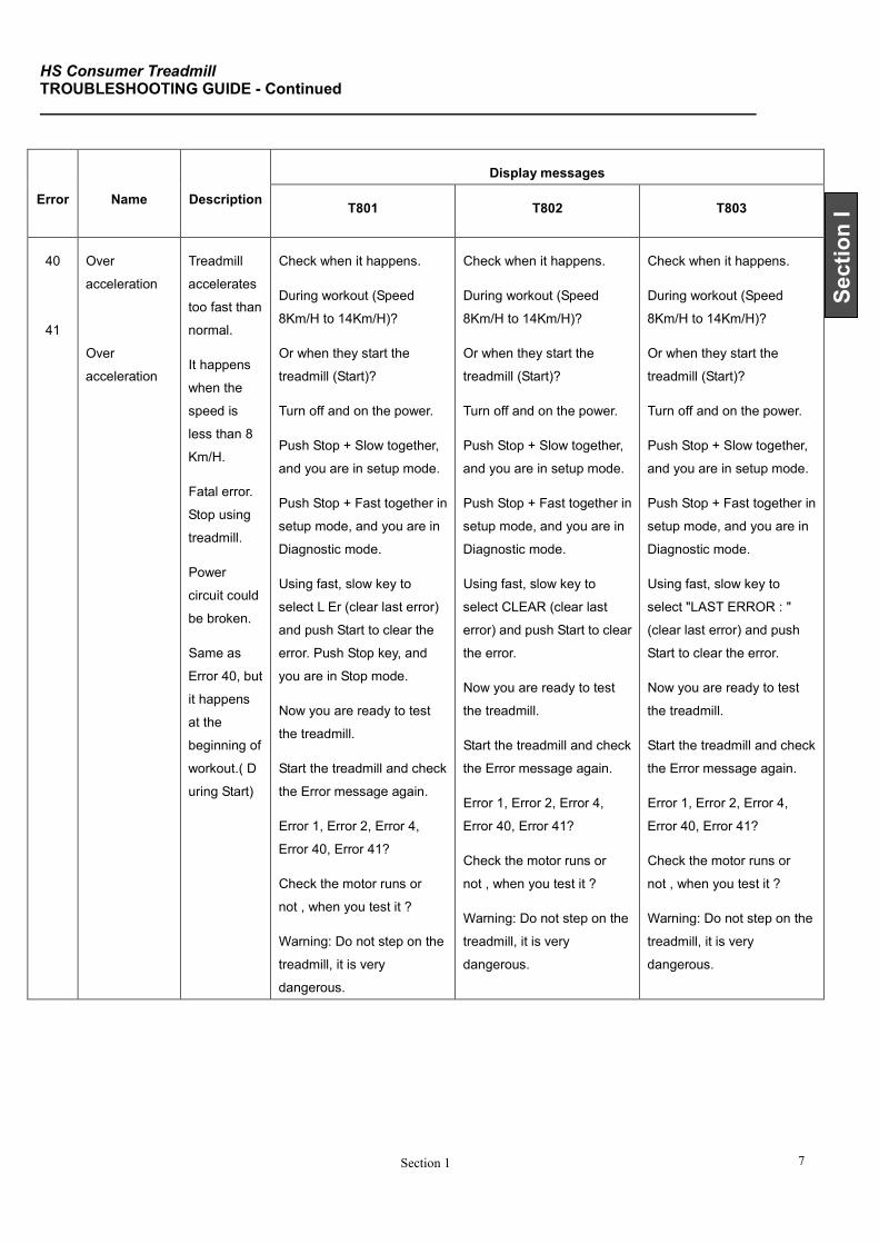
40
41
Over
acceleration
Over
acceleration
Treadmill
accelerates
too fast than
normal.
It happens
when the
speed is
less than 8
Km/H.
Fatal error.
Stop using
treadmill.
Power
circuit could
be broken.
Same as
Error 40, but
it happens
at the
beginning of
workout.( D
uring Start)
Check when it happens.
During workout (Speed
8Km/H to 14Km/H)?
Or when they start the
treadmill (Start)?
Turn off and on the power.
Push Stop + Slow together,
and you are in setup mode.
Push Stop + Fast together in
setup mode, and you are in
Diagnostic mode.
Using fast, slow key to
select L Er (clear last error)
and push Start to clear the
error. Push Stop key, and
you are in Stop mode.
Now you are ready to test
the treadmill.
Start the treadmill and check
the Error message again.
Error 1, Error 2, Error 4,
Error 40, Error 41?
Check the motor runs or
not , when you test it ?
Warning: Do not step on the
treadmill, it is very
dangerous.
Check when it happens.
During workout (Speed
8Km/H to 14Km/H)?
Or when they start the
treadmill (Start)?
Turn off and on the power.
Push Stop + Slow together,
and you are in setup mode.
Push Stop + Fast together in
setup mode, and you are in
Diagnostic mode.
Using fast, slow key to
select CLEAR (clear last
error) and push Start to clear
the error.
Now you are ready to test
the treadmill.
Start the treadmill and check
the Error message again.
Error 1, Error 2, Error 4,
Error 40, Error 41?
Check the motor runs or
not , when you test it ?
Warning: Do not step on the
treadmill, it is very
dangerous.
Check when it happens.
During workout (Speed
8Km/H to 14Km/H)?
Or when they start the
treadmill (Start)?
Turn off and on the power.
Push Stop + Slow together,
and you are in setup mode.
Push Stop + Fast together in
setup mode, and you are in
Diagnostic mode.
Using fast, slow key to
select "LAST ERROR : "
(clear last error) and push
Start to clear the error.
Now you are ready to test
the treadmill.
Start the treadmill and check
the Error message again.
Error 1, Error 2, Error 4,
Error 40, Error 41?
Check the motor runs or
not , when you test it ?
Warning: Do not step on the
treadmill, it is very
dangerous.

HS Consumer Treadmill TROUBLESHOOTING GUIDE
Section 1 8
(2) Console
Error Name Description
6 Memory EEPROM of console error, EEPROM problem or circuit problem.
Frequency is very low.
7
10
Version
Communication
Console CPU doesn’t match controller CPU.
Console doesn’t send message to MCB.
HS Consumer Treadmill OPERATING CONSOLE
Section 2 1
Section II
SECTION II
OPERATING CONSOLE
HS Consumer Treadmill OPERATING T801 CONSOLE
Section 1 2
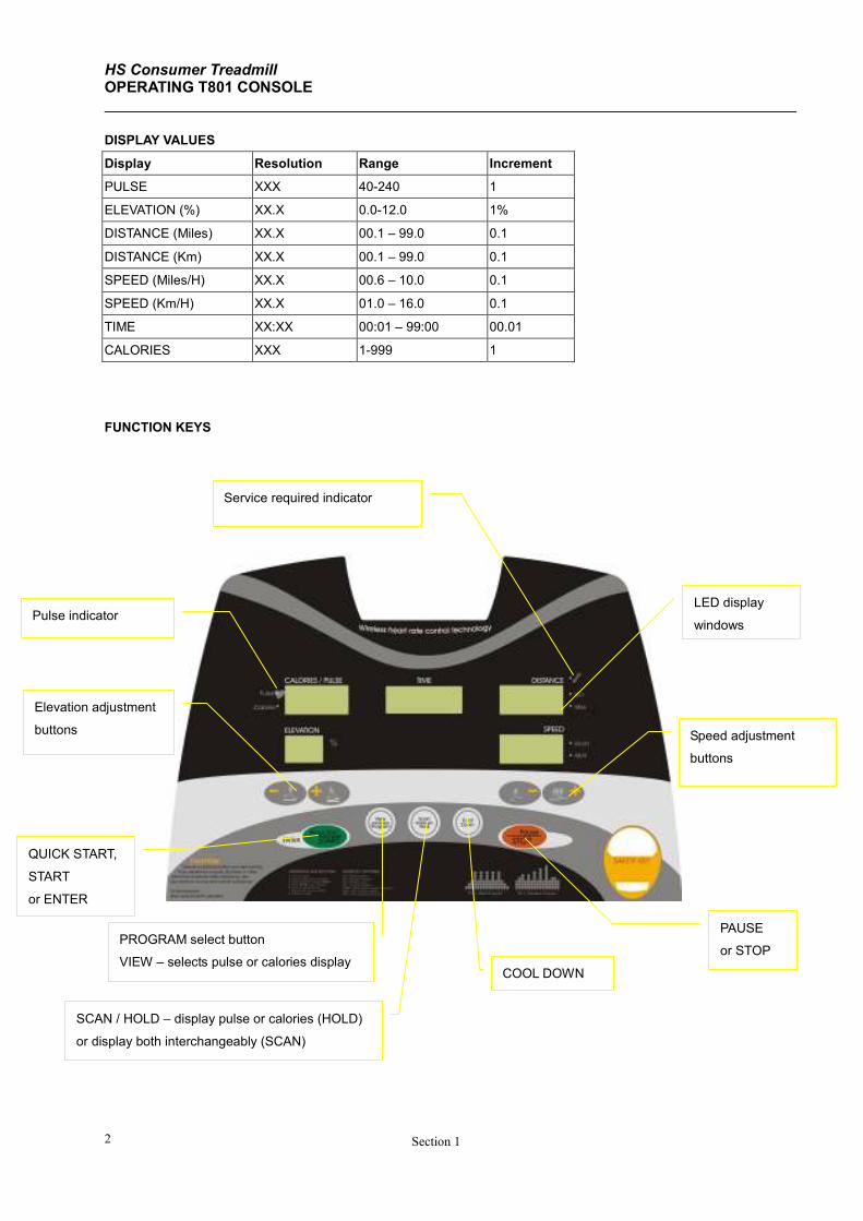
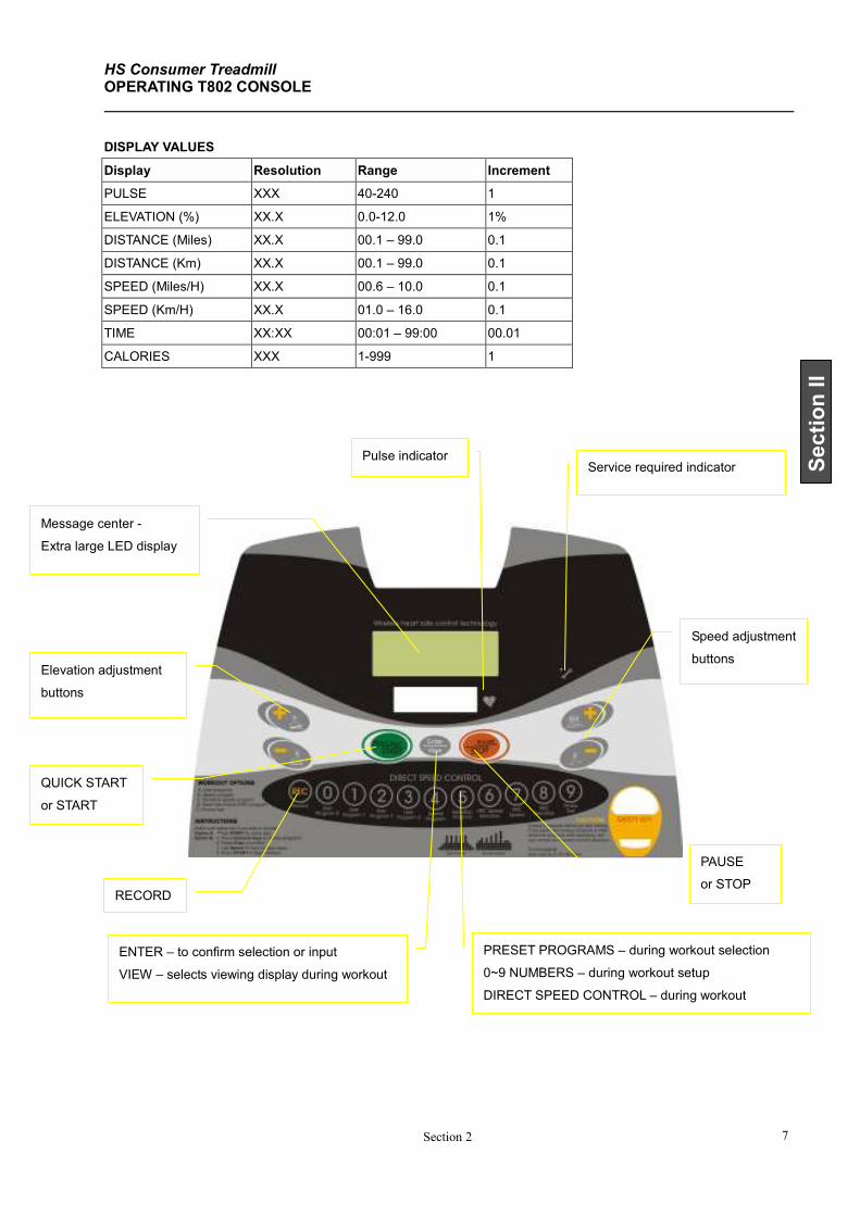
DISPLAY VALUES
Display Resolution Range Increment
PULSE XXX 40-240 1
ELEVATION (%) XX.X 0.0-12.0 1%
DISTANCE (Miles) XX.X 00.1 – 99.0 0.1
DISTANCE (Km) XX.X 00.1 – 99.0 0.1
SPEED (Miles/H) XX.X 00.6 – 10.0 0.1
SPEED (Km/H) XX.X 01.0 – 16.0 0.1
TIME XX:XX 00:01 – 99:00 00.01
CALORIES XXX 1-999 1
FUNCTION KEYS
QUICK START,
START
or ENTER
PAUSE
or STOP
Speed adjustment
buttons
Elevation adjustment
buttons
Service required indicator
Pulse indicator LED display
windows
SCAN / HOLD – display pulse or calories (HOLD)
or display both interchangeably (SCAN)
COOL DOWN
PROGRAM select button
VIEW – selects pulse or calories display
HS Consumer Treadmill OPERATING T801 CONSOLE - Continued
Section 2 3
Section II
SPEED ADJUSTMENTS
Speed + and Speed – will adjust speed by increments of 0.1Km/H during workout. Or you may hold these buttons to
ramp up or down.
ELEVATION ADJUSTMENTS
For safety reasons, elevation is designed to be manually adjusted only. At no time will treadmill automatically adjust
elevation except during one of the following three programs workout: P2 = elevation program, H-SE = HRC by speed and
elevation, and H-E = HEC by elevation.
Elevation may be adjusted even while the running belt is not moving. However, during the program setup mode,
elevation will not be adjustable.
PULSE FUNCTION
This treadmill features wireless heart rate monitoring, the most advanced technology to date for accurate read out of
your heart beat.
To use the wireless pulse monitoring system, you must wear the heart rate transmitter chest strap so that the contact
surface is next to your skin directly under your heart to pick up the pulse signals from your heart. There is a heart rate
transmitter strap included with this treadmill.
Please note that some fibers used in clothes (e.g. polyester, polyamide) create static electricity which may prevent
reliable heart rate measurement. Also note that mobile phone, television and other electrical appliances form an
electro-magnetic field around them, which may also cause problems in heart rate measurement.
PAUSE FUNCTION
When STOP button is pressed during workout, program is suspended. After the running belt has come to a complete
stop, display will count down from 03:00. During pause mode, only START and STOP buttons will function.
If START is pressed within three minutes during the pause mode, treadmill will bring the running belt movement back to
the speed at which the treadmill was paused. Workout values will resume counting and continue where it was left off.
If STOP is pressed during the pause mode, program will end. After three minutes if no button is pressed, treadmill will
automatically end the workout program.
END OF WORKOUT STATS
When you have completed your workout, the display windows will report your workout stats for one minute. After the
running belt has come to a complete stop, the displays will show total time, total distance, total calories and average
speed. Then the display will go to idle mode, ready for the next user workout setup. If you wish to skip the workout
stats report, simply press the STOP button, which will skip display to the idle mode.
UNIT CONVERSION
To change from metric to English or English to metric, you must be in the idle mode. Follow the steps below to make
the unit conversion.
1. Simultaneously press both the STOP and SPEED– buttons.
HS Consumer Treadmill OPERATING T801 CONSOLE - Continued
Section 1 4
2. The message center will display UNIT
3. Simply press START to confirm.
VIEW / PROGRAM
During workout setup – this button will select program.
During workout – this button will change PULSE to CALORIES or CALORIES to PULSE.
SCAN / HOLD
This button will allow user to view calories and pulse display values interchangeably (SCAN).
User may also view calories or pulse only.
COOL DOWN
Whenever you are ready to stop your workout, even if you are in the middle of a program, be sure to use the COOL
DOWN program. When the cool down button is pressed, it will automatically interrupt the current workout and go
directly into cool down routine, which is programmed for four minutes. The first two minutes will reduce speed and
elevation by 50% of your last display values. The last two minutes will reduce speed by another 50% and the elevation
will reduce to 0%.
PRESET PROGRAMS
QUICK START
Once the power is turned on and the safety key is secured in place, simply press the QUICK START button. Treadmill
will activate at 1.0 Km/H after 3 seconds. You may increase or decrease speed and elevation at any time during your
workout. To end workout, simply press the STOP button to stop. During manual quick start workout, time will count up.
During other program workouts, time will count down.
1. Turn power on
2. Check safety key secured to treadmill and clip secured to user clothing
3. Press START to begin workout
NOTE: Once the power is on and the safety tether key is secured in place, simply press the green start button,
and a three second count down will activate and maintain the running mat at 1Km/H.
SPEED PROGRAMS
Once the power is turned on and the safety key is secured in place, you may press the program button to choose the
pre-set speed program P1, press START key to activate the treadmill. Where user may customize, the default value (or
the previous input value) will flash indicating that you may either confirm the value flashing or change the value. Once
you have your data input, press START to activate the treadmill.
1. Turn power on
2. Check safety key secured to treadmill and clip secured to user clothing
3. Press the PROGRAM button once, P1 (speed program) will be displayed
4. Press ENTER to confirm
5. Use SPEED+ or SPEED– button to input workout time
6. Press ENTER to confirm
7. Use SPEED+ or SPEED– button to input intensity level based on maximum speed
8. Press START to begin workout
HS Consumer Treadmill OPERATING T801 CONSOLE - Continued
Section 2 5
Section II
ELEVATION PROGRAMS
Once the power is turned on and the safety key is secured in place, you may press the program button twice to choose
the pre-set elevation program P2. Where user may customize, the default value (or the previous input value) will flash
indicating that you may either confirm the value flashing or change the value. Once you have your data input, press
START to activate the treadmill.
1. Turn power on
2. Check safety key secured to treadmill and clip secured to user clothing
3. Press the program button twice, P2 (elevation program) will be displayed
4. Press ENTER to confirm
5. Use SPEED+ or SPEED– button to input workout time
6. Press ENTER to confirm
7. Use SPEED+ or SPEED– button to input intensity level based on maximum elevation
8. Press START to begin workout
TARGET TRAINING PROGRAMS
User has the option to customize workout based on setting training targets for time and distance. Once the power is on
and the safety key is secured in place, you may press the program button to choose one of the target programs. P3 and
P4 set training targets based on time and distance accordingly. Where user may customize, the default value (or the
previous input value) will flash indicating that you may either confirm the value flashing or change the value. Once you
have your data input, press START to activate the treadmill.
1. Turn power on
2. Check if safety key secured to treadmill and clip secured to user clothing
3. Press the PROGRAM button three times for P3 = Target time,
or press the PROGRAM button four times for P4 = Target distance
4. Press ENTER to confirm
5. Use SPEED+ or SPEED– button to input target time or distance
6. Press START to begin workout
HEART RATE CONTROL PROGRAMS
User has the option to customize their heart rate control programs based on their target heart rate value. Once the
power is turned on and the safety key is secured in place, you may press the PROGRAM button to select H-SE, H-S or
H-E program. Where user may customize, the default value (or the previous input value) will flash indicating that you
may either confirm or change the value flashing. Once you have your data input, press START to activate the treadmill.
Treadmill will automatically adjust by elevation, speed or both (depending on which program is chosen) to reach and
maintain the user’s target heart rate. During workout, user may still be able to adjust speed or elevation. Time will
count down from total time, which is defined to be total time of workout and cool down.
At the end of workout, treadmill will automatically go into cool down mode. Default time is set for 4 minutes. In the first
two minutes, speed and elevation will be reduced by 50%. The last two minutes, speed will be reduced by another 50%
and elevation will go to 0%.
HS Consumer Treadmill OPERATING T801 CONSOLE - Continued
Section 1 6
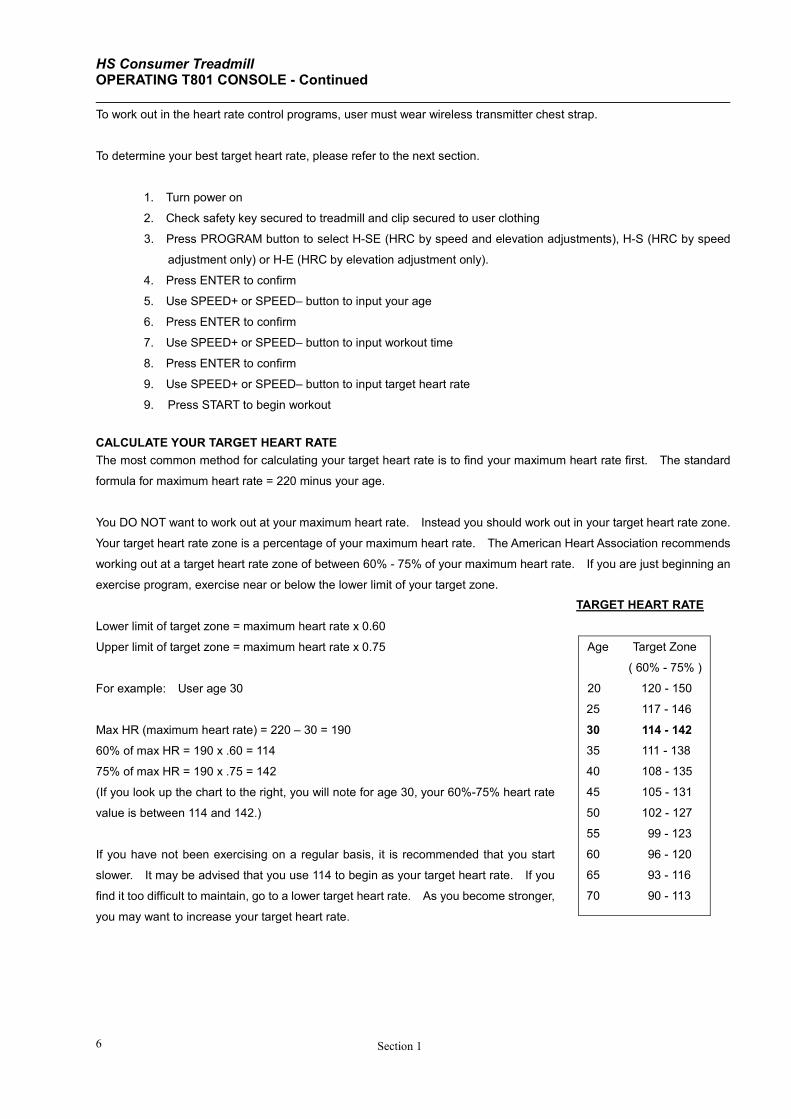
TARGET HEART RATE
Age Target Zone
( 60% - 75% )
20 120 - 150
25 117 - 146
30 114 - 142
35 111 - 138
40 108 - 135
45 105 - 131
50 102 - 127
55 99 - 123
60 96 - 120
65 93 - 116
70 90 - 113
To work out in the heart rate control programs, user must wear wireless transmitter chest strap.
To determine your best target heart rate, please refer to the next section.
1. Turn power on
2. Check safety key secured to treadmill and clip secured to user clothing
3. Press PROGRAM button to select H-SE (HRC by speed and elevation adjustments), H-S (HRC by speed
adjustment only) or H-E (HRC by elevation adjustment only).
4. Press ENTER to confirm
5. Use SPEED+ or SPEED– button to input your age
6. Press ENTER to confirm
7. Use SPEED+ or SPEED– button to input workout time
8. Press ENTER to confirm
9. Use SPEED+ or SPEED– button to input target heart rate
9. Press START to begin workout
CALCULATE YOUR TARGET HEART RATE
The most common method for calculating your target heart rate is to find your maximum heart rate first. The standard
formula for maximum heart rate = 220 minus your age.
You DO NOT want to work out at your maximum heart rate. Instead you should work out in your target heart rate zone.
Your target heart rate zone is a percentage of your maximum heart rate. The American Heart Association recommends
working out at a target heart rate zone of between 60% - 75% of your maximum heart rate. If you are just beginning an
exercise program, exercise near or below the lower limit of your target zone.
Lower limit of target zone = maximum heart rate x 0.60
Upper limit of target zone = maximum heart rate x 0.75
For example: User age 30
Max HR (maximum heart rate) = 220 – 30 = 190
60% of max HR = 190 x .60 = 114
75% of max HR = 190 x .75 = 142
(If you look up the chart to the right, you will note for age 30, your 60%-75% heart rate
value is between 114 and 142.)
If you have not been exercising on a regular basis, it is recommended that you start
slower. It may be advised that you use 114 to begin as your target heart rate. If you
find it too difficult to maintain, go to a lower target heart rate. As you become stronger,
you may want to increase your target heart rate.
HS Consumer Treadmill OPERATING T802 CONSOLE
Section 2 7
Section II
DISPLAY VALUES
Display Resolution Range Increment
PULSE XXX 40-240 1
ELEVATION (%) XX.X 0.0-12.0 1%
DISTANCE (Miles) XX.X 00.1 – 99.0 0.1
DISTANCE (Km) XX.X 00.1 – 99.0 0.1
SPEED (Miles/H) XX.X 00.6 – 10.0 0.1
SPEED (Km/H) XX.X 01.0 – 16.0 0.1
TIME XX:XX 00:01 – 99:00 00.01
CALORIES XXX 1-999 1
QUICK START
or START
PAUSE
or STOP
Speed adjustment
buttons Elevation adjustment
buttons
ENTER – to confirm selection or input
VIEW – selects viewing display during workout
PRESET PROGRAMS – during workout selection
0~9 NUMBERS – during workout setup
DIRECT SPEED CONTROL – during workout
Service required indicator Pulse indicator
Message center -
Extra large LED display
RECORD
HS Consumer Treadmill OPERATING T802 CONSOLE - Continued
Section 1 8
SPEED ADJUSTMENTS
There are three ways to adjust speed during workout. SPEED+ and SPEED– will adjust speed by increment of
0.1Km/H. Or you may hold these buttons to ramp up or down. If the speed adjustment increment is large, it is easier
to use the numeric buttons which function as direct speed control buttons during the workout. Another way to adjust
speed is to press the extension-keys on the handle bar cover. Extension-keys SPEED+ and SPEED– will also adjust
speed by increments of 0.1Km/H.
Example: to change from 3 Km/H to 8 Km/H, just press the number 8 button once. Also we could press and hold the
SPEED+ button or extension-key SPEED+ until the speed display shows 8 Km/H.
ELEVATION ADJUSTMENTS
For safety reasons, elevation is designed to be manually adjusted only. At no time will treadmill automatically adjust
elevation except during one of the following four programs: elevation program, HRC by elevation, HRC by elevation and
speed, fitness test.
Elevation may be adjusted even while the running belt is not moving. However, during the program setup mode,
elevation will not be adjustable.
There are two ways to adjust elevation during workout: GRADE+ and GRADE– on the console, extension-keys GRADE+
and GRADE– on the handle bar cover. The buttons will adjust elevation by increments of 1%.
PULSE FUNCTION
This treadmill features wireless heart rate monitoring, the most advanced technology to date for accurate read out of
your heart beat.
To use the wireless pulse monitoring system, you must wear the heart rate transmitter chest strap so that the contact
surface is next to your skin directly under your heart to pick up the pulse signals from your heart.
Please note that some fibers used in clothes (e.g. polyester, polyamide) create static electricity which may prevent
reliable heart rate measurement. Also note that mobile phone, television and other electrical appliances form an
electro-magnetic field around them, which may also cause problems in heart rate measurement.
PAUSE FUNCTION
When STOP button is pressed during workout, program is suspended. Message center will flash “PAUSE”. After the
running belt has come to a complete stop, dot matrix display window will count down from 3:00. During pause mode,
only START and STOP buttons will function.
If START is pressed within three minutes during the pause mode, treadmill will bring the running belt movement back to
the speed at which the treadmill was paused. Workout values will resume counting and continue where it was left off.
If STOP is pressed during the pause mode, program will end. After three minutes if no button is pressed, treadmill will
automatically end the workout program.
END OF WORKOUT STATS
When you have completed your workout or if you have ended your workout, message center will display twice the
HS Consumer Treadmill OPERATING T802 CONSOLE - Continued
Section 2 9
Section II
following stats: total time, total distance, total calories, average speed and average pulse. Then the display will go to
idle mode and ready for the next user workout setup. If you wish to skip the workout stats report, simply press the
STOP button, which will skip display to the idle mode. Idle mode will display PICK PROG OR PRESS START.
UNIT CONVERSION
To change from metric to English or English to metric, you must be in the idle mode, where the display shows “PICK
PROG OR PRESS START”. Follow the steps below to make the unit conversion.
1. Simultaneously press both the STOP and SPEED– buttons.
2. The message center will display Km to Mi or Mi to Km.
3. Simply press START to confirm.
Once you have begun workout, the speed unit will have changed the measurement unit accordingly.
PRESET PROGRAMS
QUICK START
Once the power is turned on and the safety key is secured in place, simply press the quick start button. Treadmill will
activate at 1.0 Km/H after 3 seconds. You may increase or decrease speed or elevation at any time during your workout.
To end workout, simply press the STOP button. During workout, time will count up.
1. Turn power on
2. Check if safety key secured to treadmill and clip secured to user clothing
3. Press START to begin workout
NOTE: Once the power is on and the safety tether key is secured in place, simply press the green START button,
and a three second count down will activate and maintain the running mat at 1Km/H.
CUSTOM PROGRAMS
At the end of any workout, except heart rate control programs and the fitness test, you have the option to save your
workout routine to any one of the four locations marked as USER PROGRAM. At the end of the workout, the message
center will flash ”SAVE”. While it is still flashing, press REC and one of the four buttons from 0 to 3. When REC is
pressed, “REC” will show up on the display and your button number will show up. Once REC # (0~3) display changed
into PROG # (0~3), it means that the program is saved.
To recall the program, press button USER PROGRAM 0~3, ENTER to confirm and press START to activate program.
Treadmill has no default recorded in the custom programs. You must save your program first before you may recall.
1. Turn power on
2. Check safety key secured to treadmill and clip secured to user clothing
3. Press numeric buttons 0 to 3 to select custom program
4. Display will show program selected
5. Press ENTER to confirm
6. Press START to begin workout
HS Consumer Treadmill OPERATING T802 CONSOLE - Continued
Section 1 10
SPEED PROGRAMS
Once the power is turned on and the safety key is secured in place, you may press the numeric button 4 to choose the
pre-set speed program. Message center will prompt user to set up workout duration, and intensity level based on max
speed value. Once you have made your selection, press START key to activate the treadmill.
During workout, treadmill will automatically adjust speed according to pre-set program setting. User may still be able to
adjust speed if the preset is not appropriate. The entire remaining program will scale up or down accordingly. During
workout, user may adjust elevation level at will. To end workout, simply press the STOP button to stop the treadmill.
During workout, time counts down from target workout time.
1. Turn power on
2. Check safety key secured to treadmill and clip secured to user clothing
3. Press 4 for SPEED program
4. Display will show “SPD P” for speed program
5. Press ENTER to confirm
6. Use numeric buttons to input workout duration. Default value will flash. You may change or confirm
value.
7. Press ENTER to confirm
8. Use numeric buttons to input intensity level based on maximum speed. Default value will flash. You may
change or confirm value.
9. Press ENTER to confirm
10. Press START to begin workout
ELEVATION PROGRAMS
Once the power is turned on and the safety key is secured in place, you may press the numeric button 5 to choose the
pre-set elevation program. Message center will prompt user to set up workout duration and intensity level based on
max elevation value. Once you have made your selection, press START key to activate the treadmill.
During workout, treadmill will automatically adjust elevation according to pre-set program setting. User may still be able
to adjust elevation if the preset is not appropriate. The entire remaining program will scale up or down accordingly.
During workout, user may adjust speed level at will. To end workout, simply press the STOP button. During workout,
time counts down from target workout time.
1. Turn power on
2. Check safety key secured to treadmill and clip secured to user clothing
3. Press 5 for elevation program
4. Display will show “GRD P” for grade (elevation) program
5. Press ENTER to confirm
6. Use numeric buttons to input workout duration. Default value will flash. You may change or confirm
value.
7. Press ENTER to confirm
8. Use numeric buttons to input intensity level based on maximum elevation. Default value will flash. You
may change or confirm value.
9. Press ENTER to confirm
10. Press START to begin workout
HS Consumer Treadmill OPERATING T802 CONSOLE - Continued
Section 2 11
Section II
HEART RATE CONTROL PROGRAMS
User has the option to customize their heart rate control programs based on their target heart rate value. Once the
power is turned on and the safety key is secured in place, you may press the numeric button 6 to select HRC
Speed/Elevation program or number 7 to select HRC Speed program or numeric button 8 to select HRC Elevation
program. Message center will prompt user to set up workout step by step. Once you have made your selection, press
START button to activate treadmill.
User also has the option to set up their warm up speed and warm up time. During warm up, target heart rate training
function will not be in operation.
After the warm up session, treadmill will automatically adjust by elevation or speed (depending on which program is
chosen) to bring the user to the target heart rate. During workout, user may still be able to adjust speed or elevation.
During workout, time counts down from total time, which is defined to be time of workout plus warm up and cool down.
At the end of the workout time, treadmill will automatically go into cool down mode. Cool down is pre-set for 4 minutes.
In the first two minutes, speed and elevation will be reduced by 50%. The last two minutes, speed will be reduced by
another 50% while the elevation will go to 0%.
To use the heart rate control programs, user must wear wireless transmitter chest strap. Signals from contact heart rate
sensor will be off in heart rate control programs.
To determine your best target heart rate, please refer to the section on calculate your target heart rate.
1. Turn power on
2. Check safety key secured to treadmill and clip secured to user clothing
3. Press 6 to select HRC Speed/Grade program, or press 7 to select HRC Speed program, or press 8 to select
HRC Elevation program
4. Display will show program selected
5. Press ENTER to confirm
6. Use numeric buttons to input your age
7. Press ENTER to confirm
8. Use numeric buttons to input workout time
9. Press ENTER to confirm
10. Use numeric buttons to input target heart rate
11. Press ENTER to confirm
12. Use numeric buttons to input warm up time=5
13. Press ENTER to confirm
14. Use numeric buttons to input warm up speed=2
15. Press ENTER to confirm
16. Press START to begin workout
CALCULATE YOUR TARGET HEART RATE
The most common method for calculating your target heart rate is to find your maximum heart rate first. The standard
formula for maximum heart rate = 220 minus your age.
HS Consumer Treadmill OPERATING T802 CONSOLE - Continued
Section 1 12
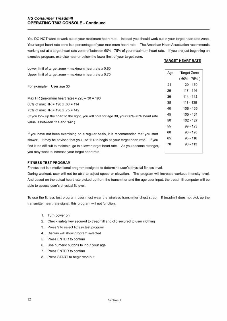
TARGET HEART RATE
Age Target Zone
( 60% - 75% )
21 120 - 150
25 117 - 146
30 114 - 142
35 111 - 138
40 108 - 135
45 105 - 131
50 102 - 127
55 99 - 123
60 96 - 120
65 93 - 116
70 90 - 113
You DO NOT want to work out at your maximum heart rate. Instead you should work out in your target heart rate zone.
Your target heart rate zone is a percentage of your maximum heart rate. The American Heart Association recommends
working out at a target heart rate zone of between 60% - 75% of your maximum heart rate. If you are just beginning an
exercise program, exercise near or below the lower limit of your target zone.
Lower limit of target zone = maximum heart rate x 0.60
Upper limit of target zone = maximum heart rate x 0.75
For example: User age 30
Max HR (maximum heart rate) = 220 – 30 = 190
60% of max HR = 190 x .60 = 114
75% of max HR = 190 x .75 = 142
(If you look up the chart to the right, you will note for age 30, your 60%-75% heart rate
value is between 114 and 142.)
If you have not been exercising on a regular basis, it is recommended that you start
slower. It may be advised that you use 114 to begin as your target heart rate. If you
find it too difficult to maintain, go to a lower target heart rate. As you become stronger,
you may want to increase your target heart rate.
FITNESS TEST PROGRAM
Fitness test is a motivational program designed to determine user’s physical fitness level.
During workout, user will not be able to adjust speed or elevation. The program will increase workout intensity level.
And based on the actual heart rate picked up from the transmitter and the age user input, the treadmill computer will be
able to assess user’s physical fit level.
To use the fitness test program, user must wear the wireless transmitter chest strap. If treadmill does not pick up the
transmitter heart rate signal, this program will not function.
1. Turn power on
2. Check safety key secured to treadmill and clip secured to user clothing
3. Press 9 to select fitness test program
4. Display will show program selected
5. Press ENTER to confirm
6. Use numeric buttons to input your age
7. Press ENTER to confirm
8. Press START to begin workout
HS Consumer Treadmill OPERATING T803 CONSOLE - Continued
Section 2 13
Section II
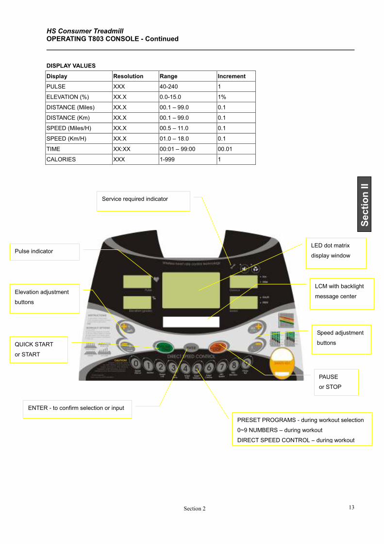
DISPLAY VALUES
Display Resolution Range Increment
PULSE XXX 40-240 1
ELEVATION (%) XX.X 0.0-15.0 1%
DISTANCE (Miles) XX.X 00.1 – 99.0 0.1
DISTANCE (Km) XX.X 00.1 – 99.0 0.1
SPEED (Miles/H) XX.X 00.5 – 11.0 0.1
SPEED (Km/H) XX.X 01.0 – 18.0 0.1
TIME XX:XX 00:01 – 99:00 00.01
CALORIES XXX 1-999 1
QUICK START
or START
PAUSE
or STOP
Speed adjustment
buttons
Elevation adjustment
buttons
ENTER - to confirm selection or input
PRESET PROGRAMS - during workout selection
0~9 NUMBERS – during workout
DIRECT SPEED CONTROL – during workout
Service required indicator
Pulse indicator LED dot matrix
display window
LCM with backlight
message center
HS Consumer Treadmill OPERATING T802 CONSOLE - Continued
Section 1 14
Section II
SPEED ADJUSTMENTS
There are three ways to adjust speed during workout. SPEED+ and SPEED– will adjust speed by increments of
0.1Km/H. Or you may hold these buttons to ramp up or down. If the speed adjustment increment is large, it is easier
to use the numeric buttons which function as direct speed control during workout. Another way to adjust speed is to
press the extension-keys on the handle bar cover. Extension-key SPEED+ and SPEED– will also adjust speed by
increments of 0.1Km/H.
Example: to change from 3 Km/H to 8 Km/H, just press the number 8 button once. Also we could press and hold the
SPEED+ button or extension-key SPEED+ until the speed display shows 8 Km/H.
ELEVATION ADJUSTMENTS
For safety reasons, elevation is designed to be manually adjusted only. At no time will treadmill automatically adjust
elevation except during one of the following four program workout: ELEVATION, HRC BY ELEVATION, FITNESS TEST.
Elevation may be adjusted even while the running belt is not moving. However, during the program setup mode,
elevation will not be adjustable.
There are two ways to adjust elevation during workout: GRADE+ and GRADE– on the console, extension-key GRADE+
and GRADE– on the handle bar cover. The buttons will adjust elevation by increments of 1%.
PULSE FUNCTION
This treadmill features wireless heart rate monitoring, the most advanced technology to date for accurate read out of
your heart beat.
To use the wireless pulse monitoring system, you must wear the heart rate transmitter chest strap so that the contact
surface is next to your skin directly under your heart to pick up the pulse signals from your heart. There is a heart rate
transmitter strap included with this treadmill.
Please note that some fibers used in clothes (e.g. polyester, polyamide) create static electricity which may prevent
reliable heart rate measurement. Also note that mobile phone, television and other electrical appliances form an
electro-magnetic field around them, which may also cause problems in heart rate measurement.
PAUSE FUNCTION
When STOP button is pressed during workout, program is suspended. Message center will flash “WORKOUT
PAUSED”. After the running belt has come to a complete stop, dot matrix display window will count down from 3:00.
During pause mode, only START and STOP buttons will function.
If START is pressed within three minutes during the pause mode, treadmill will bring the running belt movement back to
the speed at which the treadmill was paused. Workout values will resume counting and continue where it was left off.
If STOP is pressed during the pause mode, program will end. After three minutes if no button is pressed, treadmill will
automatically end the workout program.
END OF WORKOUT STATS
When you have completed your workout, the display will report your workout stats. After the running belt has come to a
complete stop, the message center will display total time, total distance, total calories and average speed twice. Then
HS Consumer Treadmill OPERATING T803 CONSOLE - Continued
Section 2 15
the display will go to idle mode, ready for the next user workout setup. If you wish to skip the workout stats report,
simply press the STOP button, which will skip display to the idle mode.
UNIT CONVERSION
To change from metric to English or English to metric, you must be in the idle mode, where the dot matrix window
displays a flashing heart. Follow the steps below to make the unit conversion.
1. Simultaneously press both the STOP and SPEED– buttons.
2. The message center will display Km to Mi or Mi to Km.
3. Simply press START to confirm.
Notice that the LED light next to the distance display window on the upper right corner will have changed the
measurement unit accordingly.
PRESET PROGRAMS
QUICK START
Once the power is turned on and the safety key is secured in place, simply press the green quick start button. Treadmill
will activate at 1.0 Km/H. You may increase or decrease speed or elevation at any time during your workout. To end
workout, simply press the red STOP button. During workout, time will count up.
1. Turn power on
2. Check safety key secured to treadmill and clip secured to user clothing
3. Press START to begin workout
NOTE: Once the power is on and the safety tether key is secured in place, simply press the green START button,
and a three-second count down will activate and maintain the running mat at 1Km/H.
SPEED PROGRAMS
Once the power is turned on and the safety key is secured in place, you may press the numeric button 0 or 1 to choose
one of the two pre-set speed programs, SPEED INTERVAL or AEROBIC. Message center will prompt user to set up
workout duration, and intensity level based on max speed value. Once you have made your selection, press START
key to activate the treadmill.
During workout, treadmill will automatically adjust speed according to pre-set program settings. User may still be able
to adjust speed if the preset is not appropriate. The entire remaining program will scale up or down accordingly.
During workout, user may adjust elevation level at will. To end workout, simply press the red STOP button. During
workout, time counts down from target workout time.
1. Turn power on
2. Check safety key secured to treadmill and clip secured to user clothing
3. Press 0 for SPEED INTERVAL program or press 1 for AEROBIC program
4. Display will show program selected
5. Press ENTER to confirm
6. Use numeric buttons to input workout duration
7. Press ENTER to confirm
HS Consumer Treadmill OPERATING T803 CONSOLE - Continued
Section 1 16
8. Use numeric buttons to input intensity level based on maximum speed
9. Press ENTER to confirm
10. Press START to begin workout
ELEVATION PROGRAMS
Once the power is turned on and the safety key is secured in place, you may press the numeric buttons 2 or 3 to choose
one of the two pre-set elevation programs, WEIGHT LOSS or HILL CLIMB. Message center will prompt user to set up
workout duration, and intensity level based on max elevation value. Once you have made your selection, press START
to activate the treadmill.
During workout, treadmill will automatically adjust elevation according to pre-set program setting. User may still be able
to adjust elevation if the preset is not appropriate. The entire remaining program will scale up or down accordingly.
During workout, user may adjust speed level at will. To end workout, simply press the red stop button. During workout,
time counts down from target workout time.
1. Turn power on
2. Check safety key secured to treadmill and clip secured to user clothing
3. Press 2 for WEIGHT LOSS program or press 3 for HILL CLIMB program
4. Display will show program selected
5. Press ENTER to confirm
6. Use numeric buttons to input workout duration
7. Press ENTER to confirm
8. Use numeric buttons to input intensity level based on maximum elevation
9. Press ENTER to confirm
10. Press START to begin workout
TARGET TRAINING PROGRAMS
Users have the option to customize workout based on setting training targets for time, distance or calories. Once the
power is turned on and the safety key is secured in place, you may press the numeric button 4 to set training target
based on time, 5 to set training target based on distance or 6 to set training target based on calories. Message center
will prompt user to set up workout target value. Once you have made your selection, press START key to activate the
treadmill.
During workout, user may adjust speed and/or elevation at will. To end workout, simply press the red stop button
to stop the treadmill. During workout, target training value will be displayed on the dot matrix display window.
1. Turn power on
2. Check safety key secured to treadmill and clip secured to user clothing
3. Press 9 to select fitness test program
4. Display will show program selected
5. Press ENTER to confirm
6. Use numeric buttons to input training target value
7. Press ENTER to confirm
8. Press START to begin workout
HS Consumer Treadmill OPERATING T803 CONSOLE - Continued
Section 2 17
Section II
HEART RATE CONTROL PROGRAMS
User has the option to customize their heart rate control programs based on their target heart rate value. Once the
power is on and the safety key is secured in place, you may press the numeric button 7 to select HRC program adjust by
speed or numeric button 8 to select HRC program adjust by elevation. Message center will prompt user to set up
workout step by step. Once you have made your selection, press START button to activate the treadmill.
User also has the option to set up their warm up speed and warm up time. During warm up mode, target heart rate
training function will not be in operation.
After the warm up mode, treadmill will automatically adjust by elevation or speed (depending on which program is
chosen) to reach and maintain the user’s target heart rate. During workout mode, users may still be able to adjust
speed or elevation. During workout, time counts down from total time, which is defined to be time of warm up plus
workout and cool down.
At the end of the workout time, treadmill will automatically go into cool down mode. Cool down mode is pre-set up for 4
minutes. In the first two minutes, speed and elevation will be reduced by 50%. The last two minutes, speed and
elevation will be reduced by another 50%. To end workout, simply press the red STOP button to stop the treadmill.
To use the heart rate control programs, users must wear wireless transmitter chest strap. Signals from contact heart
rate sensor will not be used to maintain your target heart rate.
To determine your best target heart rate, please refer to the section on calculate your target heart rate.
1. Turn power on
2. Check safety key secured to treadmill and clip secured to user clothing
3. Press 7 to select HRC program adjust by speed changes or press 8 to select HRC program adjust by
elevation changes
4. Display will show program selected
5. Press ENTER to confirm
6. Use numeric buttons to input your age
7. Press ENTER to confirm
8. Use numeric buttons to input workout time
9. Press ENTER to confirm
10. Use numeric buttons to input target heart rate
11. Press ENTER to confirm
12. Use numeric buttons to input warm up time
13. Press ENTER to confirm
14. Use numeric buttons to input warm up speed
15. Press ENTER to confirm
16. Press START to begin workout
CALCULATE YOUR TARGET HEART RATE
The most common method for calculating your target heart rate is to find your maximum heart rate first. The standard
formula for maximum heart rate = 220 minus your age.
HS Consumer Treadmill OPERATING T803 CONSOLE - Continued
Section 1 18
TARGET HEART RATE
Age Target Zone
( 60% - 75% )
22 120 - 150
25 117 - 146
30 114 - 142
35 111 - 138
40 108 - 135
45 105 - 131
50 102 - 127
55 99 - 123
60 96 - 120
65 93 - 116
70 90 - 113
You DO NOT want to work out at your maximum heart rate. Instead you work out in your target heart rate zone. Your
target heart rate zone is a percentage of your maximum heart rate. The American Heart Association recommends
working out at a target heart rate zone of between 60% - 75% of your maximum heart rate. If you are just beginning an
exercise program, exercise near or below the lower limit of your target zone.
Lower limit of target zone = maximum heart rate x 0.60
Upper limit of target zone = maximum heart rate x 0.75
For example: User age 30
Max HR (maximum heart rate) = 220 – 30 = 190
60% of max HR = 190 x .60 = 114
75% of max HR = 190 x .75 = 142
(If you look at the chart to the right, you will note for age 30, your 60%-75% heart
rate values are 114 and 142.)
If you have not been exercising on a regular basis, it is recommended that you start
slower. It may be advised that you use 114 to begin as your target heart rate. If
you find it too difficult to maintain, go to a lower target heart rate. As you become
stronger, you may want to increase your target heart rate.
FITNESS TEST PROGRAM
Fitness test is a motivational program designed to determine user’s physical fitness level.
During workout, user will not be able to adjust speed or elevation. The program will increase workout intensity level.
And based on the actual heart rate picked up from the transmitter and the age user input, the treadmill computer will be
able to assess user’s physical fit level.
To use the fitness test program, user must wear the wireless transmitter chest strap. If treadmill does not pick up the
transmitter heart rate signal, this program will not function.
1. Turn power on
2. Check safety key secured to treadmill and clip secured to user clothing
3. Press 9 to select fitness test program
4. Display will show program selected
5. Press ENTER to confirm
6. Use numeric buttons to input your age
7. Press ENTER to confirm
8. Press START to begin workout
HS Consumer Treadmill OPERATING CONSOLE – T801 T802 SET UP AND DIAGNOSTIC MODE
19 Section 2
Section II
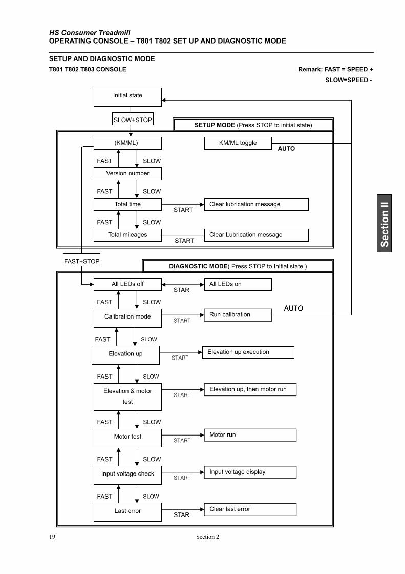
SETUP AND DIAGNOSTIC MODE
T801 T802 T803 CONSOLE Remark: FAST = SPEED +
SLOW=SPEED -
Version number
Total time
Total mileages
(KM/ML)
All LEDs off
SLOW
SLOW
SLOW
SLOW
FAST
FAST
FAST
FAST
START
STAR
Clear lubrication message
All LEDs on
KM/ML toggle
Initial state
SETUP MODE (Press STOP to initial state)
DIAGNOSTIC MODE( Press STOP to Initial state )
AUTO
Calibration mode
START Run calibration
AUTOAUTOAUTOAUTO
Motor run
SLOW FAST
Motor test START
START Clear Lubrication message
FAST+STOP
SLOW+STOP
Elevation up execution
SLOW FAST
Elevation up START
Elevation up, then motor run
SLOW FAST
Elevation & motor
test START
Input voltage display
SLOW FAST
Input voltage check START
Clear last error
SLOW FAST
Last error STAR

HS Consumer Treadmill OPERATING CONSOLE – T803 SET UP AND DIAGNOSTIC MODE
Section 1 20
HS Consumer Treadmill
Section 3 1
Section III
SECTION III
HOW TO … SERVICE AND REPAIR GUIDE
HS Consumer Treadmill How To… Replace The Running Belt and Deck Tools Required: Allen key set, Phillips screwdriver, tape measure, rubber hammer, and open end wrench set. (All
fasteners are metric. Make sure that you have metric tools.)
2 Section 1
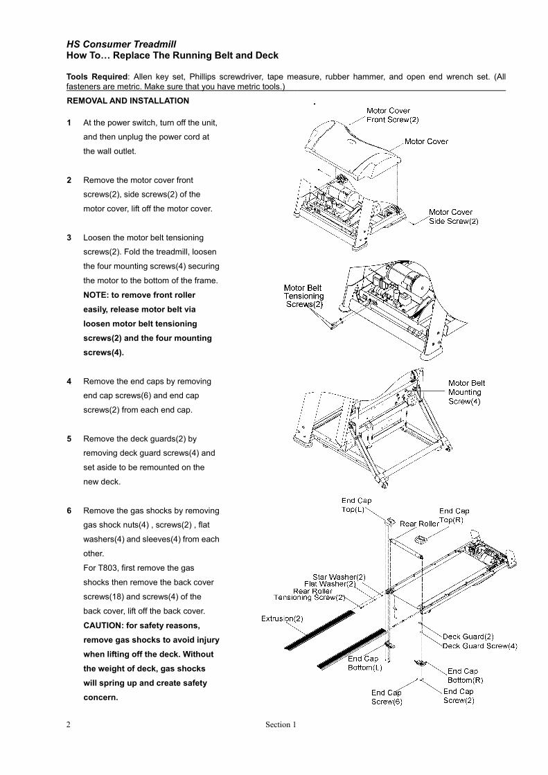
REMOVAL AND INSTALLATION
1 At the power switch, turn off the unit,
and then unplug the power cord at
the wall outlet.
2 Remove the motor cover front
screws(2), side screws(2) of the
motor cover, lift off the motor cover.
3 Loosen the motor belt tensioning
screws(2). Fold the treadmill, loosen
the four mounting screws(4) securing
the motor to the bottom of the frame.
NOTE: to remove front roller
easily, release motor belt via
loosen motor belt tensioning
screws(2) and the four mounting
screws(4).
4 Remove the end caps by removing
end cap screws(6) and end cap
screws(2) from each end cap.
5 Remove the deck guards(2) by
removing deck guard screws(4) and
set aside to be remounted on the
new deck.
6 Remove the gas shocks by removing
gas shock nuts(4) , screws(2) , flat
washers(4) and sleeves(4) from each
other.
For T803, first remove the gas
shocks then remove the back cover
screws(18) and screws(4) of the
back cover, lift off the back cover.
CAUTION: for safety reasons,
remove gas shocks to avoid injury
when lifting off the deck. Without
the weight of deck, gas shocks
will spring up and create safety
concern.
HS Consumer Treadmill How To… Replace The Running Belt and Deck - Continued Tools Required: Allen key set, Phillips screwdriver, tape measure, rubber hammer, and open end wrench set. (All
fasteners are metric. Make sure that you have metric tools.)
Section 3 3
Section III
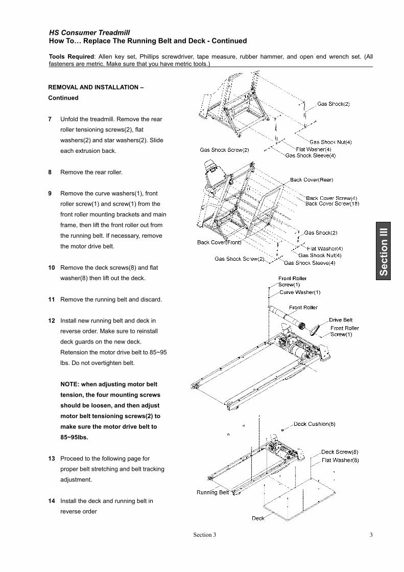
REMOVAL AND INSTALLATION –
Continued
7 Unfold the treadmill. Remove the rear
roller tensioning screws(2), flat
washers(2) and star washers(2). Slide
each extrusion back.
8 Remove the rear roller.
9 Remove the curve washers(1), front
roller screw(1) and screw(1) from the
front roller mounting brackets and main
frame, then lift the front roller out from
the running belt. If necessary, remove
the motor drive belt.
10 Remove the deck screws(8) and flat
washer(8) then lift out the deck.
11 Remove the running belt and discard.
12 Install new running belt and deck in
reverse order. Make sure to reinstall
deck guards on the new deck.
Retension the motor drive belt to 85~95
lbs. Do not overtighten belt.
NOTE: when adjusting motor belt
tension, the four mounting screws
should be loosen, and then adjust
motor belt tensioning screws(2) to
make sure the motor drive belt to
85~95lbs.
13 Proceed to the following page for
proper belt stretching and belt tracking
adjustment.
14 Install the deck and running belt in
reverse order

HS Consumer Treadmill How To… Adjust Running Belt Tracking Tools Required: Allen key set. (All fasteners are metric. Make sure that you have metric tools.)
Section 1 4
1. After the treadmill has been installed and
leveled, the belt must be checked for confirm
proper tracking. First, plug the power cord
into an appropriate outlet and turn the
treadmill power ON.
2. Press the QUICK START button then increase
speed to 8.0kph by pressing the SPEED+
button.
3. If the running belt has moved to the RIGHT,
turn the RIGHT tension bolt 1/4 turn
CLOCKWISE and the left tension bolt 1/4 turn
counterclockwise to start the running belt
tracking back to the center of the rear roller.
If the running belt has moved to the LEFT,
turn the left tension bolt 1/4 turn CLOCKWISE
and the right tension bolt 1/4 turn
counterclockwise to start the running belt
tracking back to the center of the rear roller.
4. Repeat this adjustment until the running belt appears centered. The belt should be equal distance
(B) on both sides of the rear roller.
5. Allow the unit to operate for several minutes to see if the belt remains centered.
NOTE: During the adjustment above, DO NOT exceed one full turn of the adjusting screws in
either direction.
HS Consumer Treadmill How To… Adjust Running Belt Tension Tools Required: Allen key set. (All fasteners are metric. Make sure that you have metric tools.)
Section 3 5
Section III
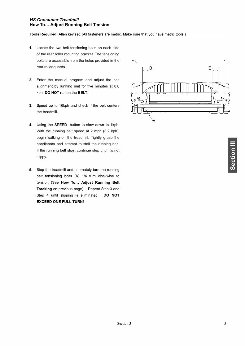
1. Locate the two belt tensioning bolts on each side
of the rear roller mounting bracket. The tensioning
bolts are accessible from the holes provided in the
rear roller guards.
2. Enter the manual program and adjust the belt
alignment by running unit for five minutes at 8.0
kph. DO NOT run on the BELT.
3. Speed up to 16kph and check if the belt centers
the treadmill.
4. Using the SPEED- button to slow down to 1kph.
With the running belt speed at 2 mph (3.2 kph),
begin walking on the treadmill. Tightly grasp the
handlebars and attempt to stall the running belt.
If the running belt slips, continue step until it’s not
slippy.
5. Stop the treadmill and alternately turn the running
belt tensioning bolts (A) 1/4 turn clockwise to
tension (See How To… Adjust Running Belt
Tracking on previous page). Repeat Step 3 and
Step 4 until slipping is eliminated. DO NOT
EXCEED ONE FULL TURN!
HS Consumer Treadmill How To…Replace The Motor Drive Belt Tools Required: Allen key set, Phillips screwdriver, and open end wrench set. (All fasteners are metric. Make sure that
you have metric tools.)
Section 1 6
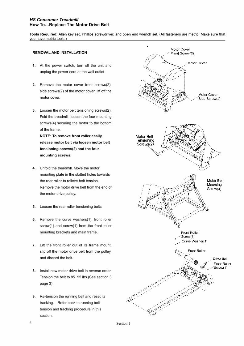
REMOVAL AND INSTALLATION
1. At the power switch, turn off the unit and
unplug the power cord at the wall outlet.
2. Remove the motor cover front screws(2),
side screws(2) of the motor cover, lift off the
motor cover.
3. Loosen the motor belt tensioning screws(2),
Fold the treadmill, loosen the four mounting
screws(4) securing the motor to the bottom
of the frame.
NOTE: To remove front roller easily,
release motor belt via loosen motor belt
tensioning screws(2) and the four
mounting screws.
4. Unfold the treadmill. Move the motor
mounting plate in the slotted holes towards
the rear roller to relieve belt tension.
Remove the motor drive belt from the end of
the motor drive pulley.
5. Loosen the rear roller tensioning bolts
6. Remove the curve washers(1), front roller
screw(1) and screw(1) from the front roller
mounting brackets and main frame.
7. Lift the front roller out of its frame mount,
slip off the motor drive belt from the pulley,
and discard the belt.
8. Install new motor drive belt in reverse order.
Tension the belt to 85~95 lbs.(See section 3
page 3)
9. Re-tension the running belt and reset its
tracking. Refer back to running belt
tension and tracking procedure in this
section.
HS Consumer Treadmill How To…Replace The Drive Motor Tools Required: Allen key set, Phillips screwdriver, and open end wrench set. (All fasteners are metric. Make sure that
you have metric tools.)
Section 3 7
Section III
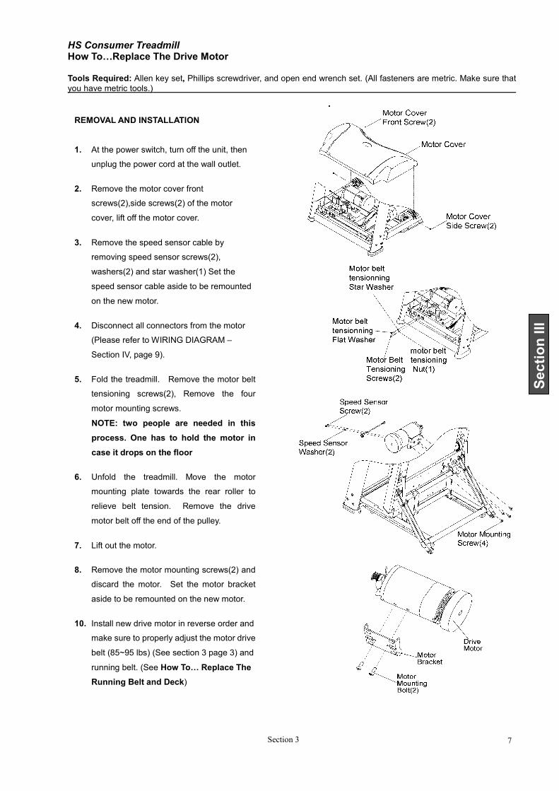
REMOVAL AND INSTALLATION
1. At the power switch, turn off the unit, then
unplug the power cord at the wall outlet.
2. Remove the motor cover front
screws(2),side screws(2) of the motor
cover, lift off the motor cover.
3. Remove the speed sensor cable by
removing speed sensor screws(2),
washers(2) and star washer(1) Set the
speed sensor cable aside to be remounted
on the new motor.
4. Disconnect all connectors from the motor
(Please refer to WIRING DIAGRAM –
Section IV, page 9).
5. Fold the treadmill. Remove the motor belt
tensioning screws(2), Remove the four
motor mounting screws.
NOTE: two people are needed in this
process. One has to hold the motor in
case it drops on the floor
6. Unfold the treadmill. Move the motor
mounting plate towards the rear roller to
relieve belt tension. Remove the drive
motor belt off the end of the pulley.
7. Lift out the motor.
8. Remove the motor mounting screws(2) and
discard the motor. Set the motor bracket
aside to be remounted on the new motor.
10. Install new drive motor in reverse order and
make sure to properly adjust the motor drive
belt (85~95 lbs) (See section 3 page 3) and
running belt. (See How To… Replace The
Running Belt and Deck)
HS Consumer Treadmill How To…Replace The Front Roller Tools Required: Allen key set, Phillips screwdriver, and open end wrench set. (All fasteners are metric. Make sure that
you have metric tools.)
Section 1 8
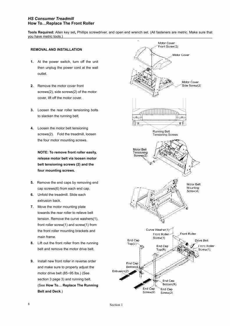
REMOVAL AND INSTALLATION
1. At the power switch, turn off the unit
then unplug the power cord at the wall
outlet.
2. Remove the motor cover front
screws(2), side screws(2) of the motor
cover, lift off the motor cover.
3. Loosen the rear roller tensioning bolts
to slacken the running belt.
4. Loosen the motor belt tensioning
screws(2). Fold the treadmill, loosen
the four motor mounting screws.
NOTE: To remove front roller easily,
release motor belt via loosen motor
belt tensioning screws (2) and the
four mounting screws.
5. Remove the end caps by removing end
cap screws(6) from each end cap.
6. Unfold the treadmill. Slide each
extrusion back.
7. Move the motor mounting plate
towards the rear roller to relieve belt
tension. Remove the curve washers(1),
front roller screw(1) and screw(1) from
the front roller mounting brackets and
main frame.
8. Lift out the front roller from the running
belt and remove the motor drive belt.
9. Install new front roller in reverse order
and make sure to properly adjust the
motor drive belt (85~95 lbs.) (See
section 3 page 3) and running belt.
(See How To… Replace The Running
Belt and Deck.)
HS Consumer Treadmill How To…Replace The Rear Roller Tools Required: Allen key set, Phillips screwdriver, rubber hammer, and open end wrench set. (All fasteners are metric.
Make sure that you have metric tools.)
Section 3 9
Section III
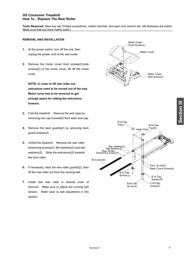
REMOVAL AND INSTALLATION
1. At the power switch, turn off the unit, then
unplug the power cord at the wall outlet.
2. Remove the motor cover front screws(2),side
screws(2) of the motor cover, lift off the motor
cover.
NOTE: In order to lift rear roller out,
extrusions need to be moved out of the way.
Motor cover has to be removed to get
enough space for sliding the extrusions
forward.
3. Fold the treadmill. Remove the end caps by
removing end cap screws(6) from each end cap.
4. Remove the deck guards(2) by removing deck
guard screws(4).
5. Unfold the treadmill. Remove the rear roller
tensioning screws(2), flat washers(2) and star
washers(2). Slide the extrusions(2) towards
the front roller.
6. If necessary, clear the rear roller guards(2), then
lift the rear roller out from the running belt.
7. Install new rear roller in reverse order of
removal. Make sure to adjust the running belt
tension. Refer back to belt adjustment in this
section.
HS Consumer Treadmill How To…Replace The Deck Cushion Tools Required: Allen key set, Phillips screwdriver, and rubber hammer. (All fasteners are metric. Make sure that you
have metric tools.)
Section 1 10
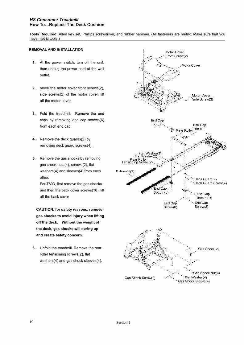
REMOVAL AND INSTALLATION
1. At the power switch, turn off the unit,
then unplug the power cord at the wall
outlet.
2. move the motor cover front screws(2),
side screws(2) of the motor cover, lift
off the motor cover.
3. Fold the treadmill. Remove the end
caps by removing end cap screws(6)
from each end cap
4. Remove the deck guards(2) by
removing deck guard screws(4).
5. Remove the gas shocks by removing
gas shock nuts(4), screws(2), flat
washers(4) and sleeves(4) from each
other.
For T803, first remove the gas shocks
and then the back cover screws(18), lift
off the back cover
CAUTION: for safety reasons, remove
gas shocks to avoid injury when lifting
off the deck. Without the weight of
the deck, gas shocks will spring up
and create safety concern.
6. Unfold the treadmill. Remove the rear
roller tensioning screws(2), flat
washers(4) and gas shock sleeves(4).
HS Consumer Treadmill How To…Replace The Deck Cushion - Continued Tools Required: Allen key set, Phillips screwdriver, and rubber hammer. (All fasteners are metric. Make sure that you
have metric tools.) ……………………………………………………………………………………..
Section 3 11
Section III
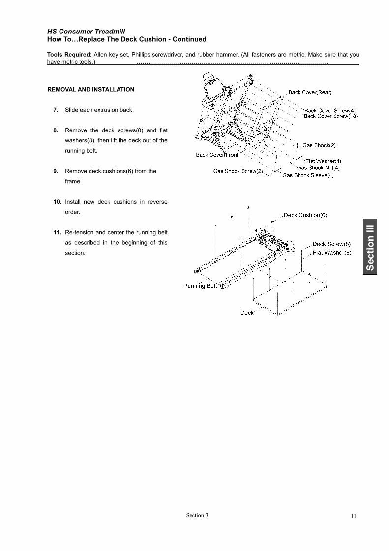
REMOVAL AND INSTALLATION
7. Slide each extrusion back.
8. Remove the deck screws(8) and flat
washers(8), then lift the deck out of the
running belt.
9. Remove deck cushions(6) from the
frame.
10. Install new deck cushions in reverse
order.
11. Re-tension and center the running belt
as described in the beginning of this
section.
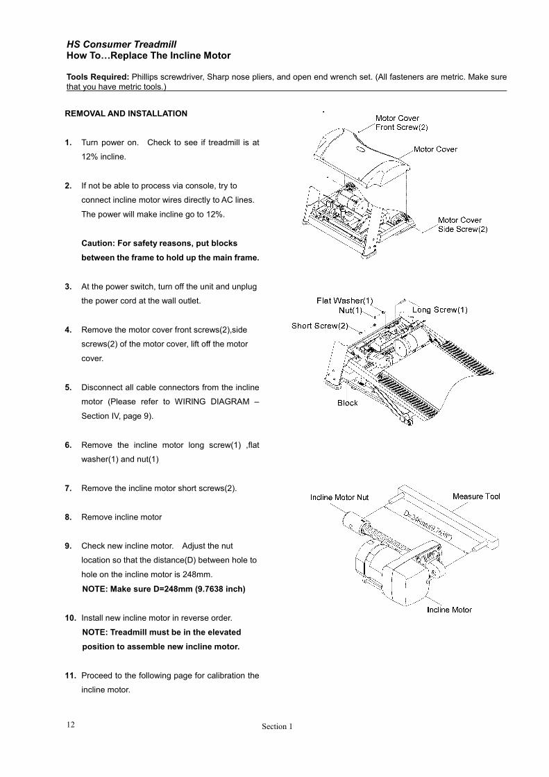
HS Consumer Treadmill How To…Replace The Incline Motor Tools Required: Phillips screwdriver, Sharp nose pliers, and open end wrench set. (All fasteners are metric. Make sure
that you have metric tools.)
Section 1 12
REMOVAL AND INSTALLATION
1. Turn power on. Check to see if treadmill is at
12% incline.
2. If not be able to process via console, try to
connect incline motor wires directly to AC lines.
The power will make incline go to 12%.
Caution: For safety reasons, put blocks
between the frame to hold up the main frame.
3. At the power switch, turn off the unit and unplug
the power cord at the wall outlet.
4. Remove the motor cover front screws(2),side
screws(2) of the motor cover, lift off the motor
cover.
5. Disconnect all cable connectors from the incline
motor (Please refer to WIRING DIAGRAM –
Section IV, page 9).
6. Remove the incline motor long screw(1) ,flat
washer(1) and nut(1)
7. Remove the incline motor short screws(2).
8. Remove incline motor
9. Check new incline motor. Adjust the nut
location so that the distance(D) between hole to
hole on the incline motor is 248mm.
NOTE: Make sure D=248mm (9.7638 inch)
10. Install new incline motor in reverse order.
NOTE: Treadmill must be in the elevated
position to assemble new incline motor.
11. Proceed to the following page for calibration the
incline motor.
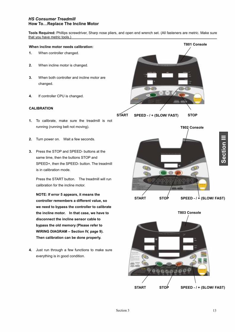
HS Consumer Treadmill How To…Replace The Incline Motor Tools Required: Phillips screwdriver, Sharp nose pliers, and open end wrench set. (All fasteners are metric. Make sure
that you have metric tools.)
Section 3 13
Section III
When incline motor needs calibration:
1. When controller changed.
2. When incline motor is changed.
3. When both controller and incline motor are
changed.
4. If controller CPU is changed.
CALIBRATION
1. To calibrate, make sure the treadmill is not
running (running belt not moving).
2. Turn power on. Wait a few seconds.
3. Press the STOP and SPEED- buttons at the
same time, then the buttons STOP and
SPEED+, then the SPEED- button. The treadmill
is in calibration mode.
Press the START button. The treadmill will run
calibration for the incline motor.
NOTE: If error 5 appears, it means the
controller remembers a different value, so
we need to bypass the controller to calibrate
the incline motor. In that case, we have to
disconnect the incline sensor cable to
bypass the old memory (Please refer to
WIRING DIAGRAM – Section IV, page 9).
Then calibration can be done properly.
4. Just run through a few functions to make sure
everything is in good condition.
T801 Console
SPEED - / + (SLOW/ FAST) STOP START
START
T802 Console
STOP SPEED - / + (SLOW/ FAST)
T803 Console
START STOP SPEED - / + (SLOW/ FAST)
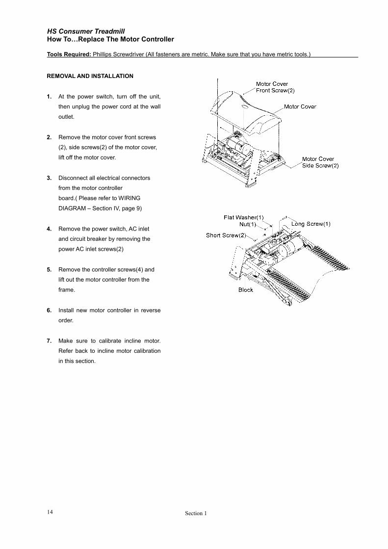
HS Consumer Treadmill How To…Replace The Motor Controller Tools Required: Phillips Screwdriver (All fasteners are metric. Make sure that you have metric tools.)
Section 1 14
REMOVAL AND INSTALLATION
1. At the power switch, turn off the unit,
then unplug the power cord at the wall
outlet.
2. Remove the motor cover front screws
(2), side screws(2) of the motor cover,
lift off the motor cover.
3. Disconnect all electrical connectors
from the motor controller
board.( Please refer to WIRING
DIAGRAM – Section IV, page 9)
4. Remove the power switch, AC inlet
and circuit breaker by removing the
power AC inlet screws(2)
5. Remove the controller screws(4) and
lift out the motor controller from the
frame.
6. Install new motor controller in reverse
order.
7. Make sure to calibrate incline motor.
Refer back to incline motor calibration
in this section.
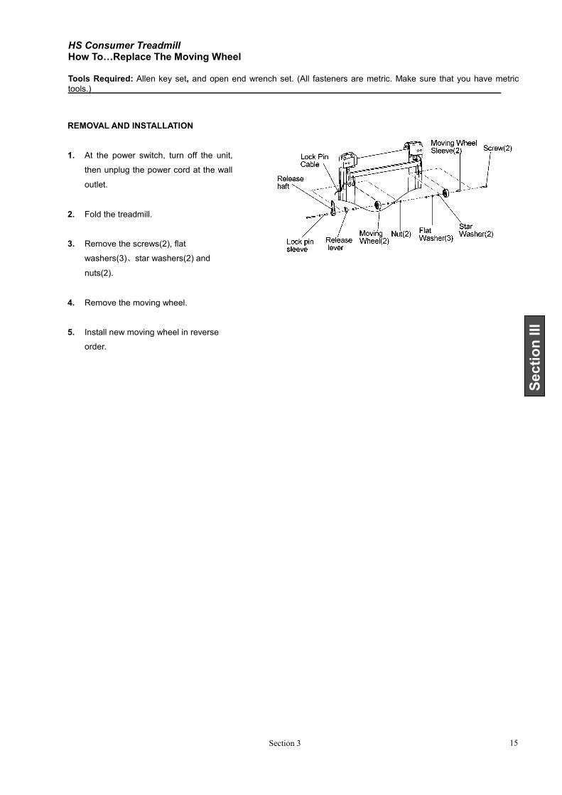
HS Consumer Treadmill How To…Replace The Moving Wheel Tools Required: Allen key set, and open end wrench set. (All fasteners are metric. Make sure that you have metric
tools.)
Section 3 15
Section III
REMOVAL AND INSTALLATION
1. At the power switch, turn off the unit,
then unplug the power cord at the wall
outlet.
2. Fold the treadmill.
3. Remove the screws(2), flat
washers(3)、star washers(2) and
nuts(2).
4. Remove the moving wheel.
5. Install new moving wheel in reverse
order.

HS Consumer Treadmill
Section 4 1
Section IV
SECTION IV
ELECTRONIC OVERVIEW AND
WIRING BLOCK DIAGRAM
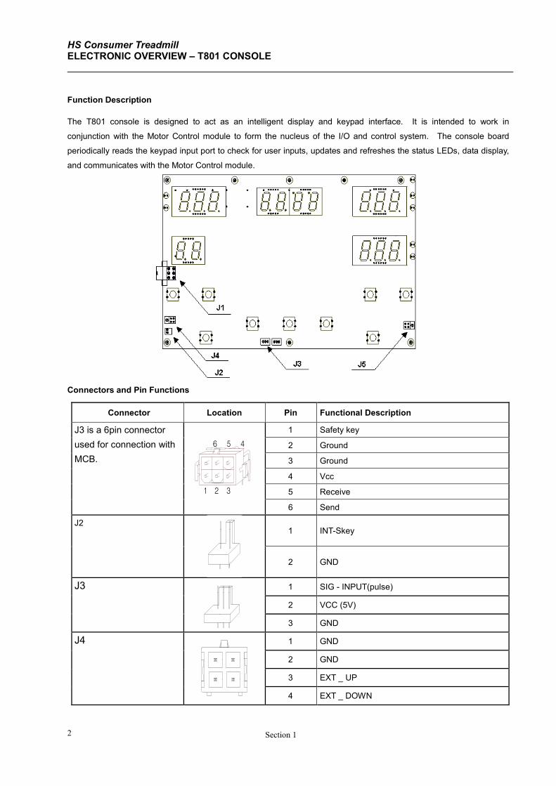
HS Consumer Treadmill ELECTRONIC OVERVIEW – T801 CONSOLE
Section 1 2
1 2
5
3
6 4
Function Description
The T801 console is designed to act as an intelligent display and keypad interface. It is intended to work in
conjunction with the Motor Control module to form the nucleus of the I/O and control system. The console board
periodically reads the keypad input port to check for user inputs, updates and refreshes the status LEDs, data display,
and communicates with the Motor Control module.
Connectors and Pin Functions
Connector Location Pin Functional Description
J3 is a 6pin connector
used for connection with
MCB.
1 Safety key
2 Ground
3 Ground
4 Vcc
5 Receive
6 Send
J2 1 INT-Skey
2 GND
J3 1 SIG - INPUT(pulse)
2 VCC (5V)
3 GND
J4 1 GND
2 GND
3 EXT _ UP
4 EXT _ DOWN
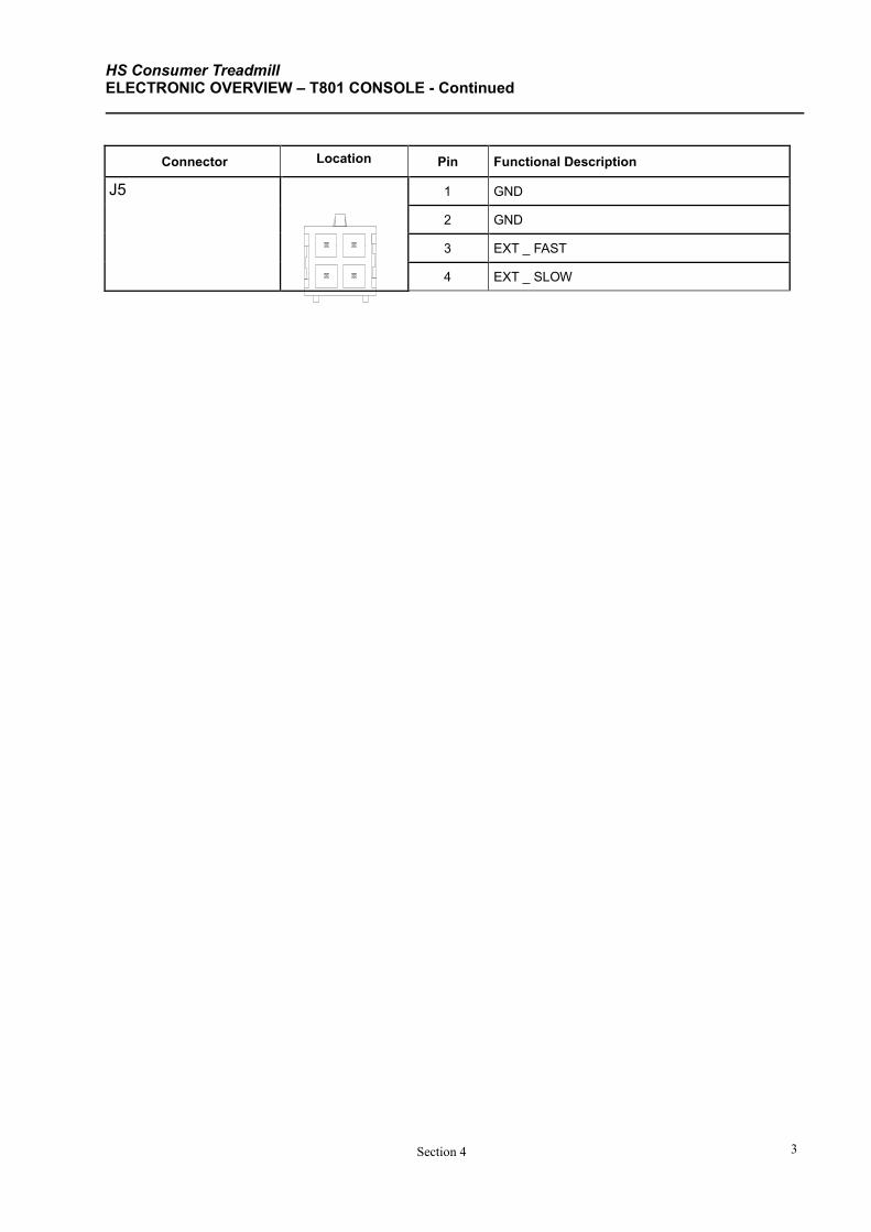
HS Consumer Treadmill ELECTRONIC OVERVIEW – T801 CONSOLE - Continued
Section 4 3
Connector Location Pin Functional Description
J5
1 GND
2 GND
3 EXT _ FAST
4 EXT _ SLOW
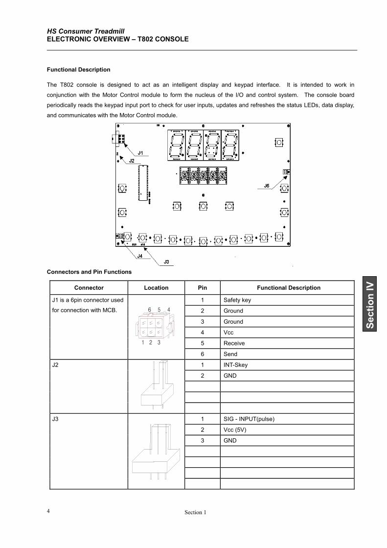
HS Consumer Treadmill ELECTRONIC OVERVIEW – T802 CONSOLE
Section 1 4
1 2
5
3
6 4
Section IV
Functional Description
The T802 console is designed to act as an intelligent display and keypad interface. It is intended to work in
conjunction with the Motor Control module to form the nucleus of the I/O and control system. The console board
periodically reads the keypad input port to check for user inputs, updates and refreshes the status LEDs, data display,
and communicates with the Motor Control module.
Connectors and Pin Functions
Connector Location Pin Functional Description
J1 is a 6pin connector used
for connection with MCB.
1 Safety key
2 Ground
3 Ground
4 Vcc
5 Receive
6 Send
J2
1 INT-Skey
2 GND
J3
1 SIG - INPUT(pulse)
2 Vcc (5V)
3 GND
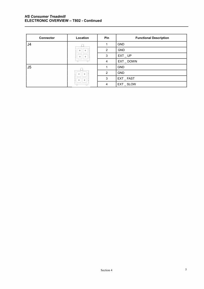
HS Consumer Treadmill ELECTRONIC OVERVIEW – T802 - Continued
Section 4 5
Connector Location Pin Functional Description
J4 1 GND
2 GND
3 EXT _ UP
4 EXT _ DOWN
J5 1 GND
2 GND
3 EXT _ FAST
4 EXT _ SLOW
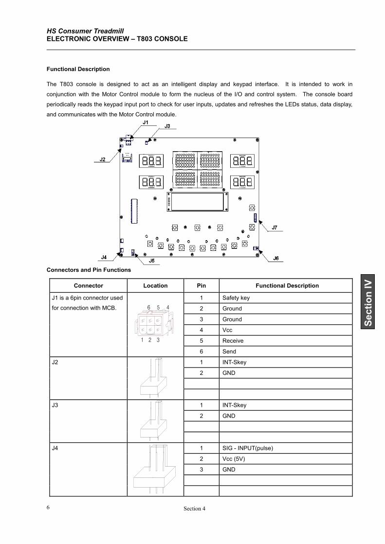
HS Consumer Treadmill ELECTRONIC OVERVIEW – T803 CONSOLE
Section 4 6
1 2
5
3
6 4
Section IV
Functional Description
The T803 console is designed to act as an intelligent display and keypad interface. It is intended to work in
conjunction with the Motor Control module to form the nucleus of the I/O and control system. The console board
periodically reads the keypad input port to check for user inputs, updates and refreshes the LEDs status, data display,
and communicates with the Motor Control module.
Connectors and Pin Functions
Connector Location Pin Functional Description
J1 is a 6pin connector used
for connection with MCB.
1 Safety key
2 Ground
3 Ground
4 Vcc
5 Receive
6 Send
J2
1 INT-Skey
2 GND
J3
1 INT-Skey
2 GND
J4
1 SIG - INPUT(pulse)
2 Vcc (5V)
3 GND
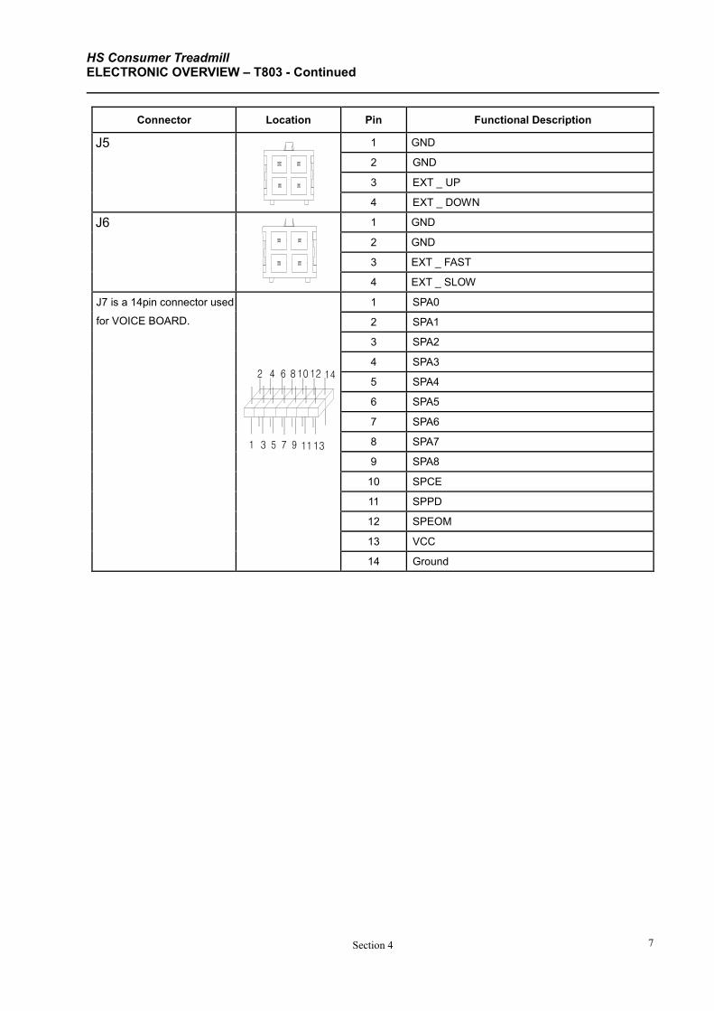
HS Consumer Treadmill ELECTRONIC OVERVIEW – T803 - Continued
Section 4 7
3
4 6
7
8
11
12
13
14
95
2 10
1
Connector Location Pin Functional Description
J5 1 GND
2 GND
3 EXT _ UP
4 EXT _ DOWN
J6 1 GND
2 GND
3 EXT _ FAST
4 EXT _ SLOW
J7 is a 14pin connector used
for VOICE BOARD.
1 SPA0
2 SPA1
3 SPA2
4 SPA3
5 SPA4
6 SPA5
7 SPA6
8 SPA7
9 SPA8
10 SPCE
11 SPPD
12 SPEOM
13 VCC
14 Ground
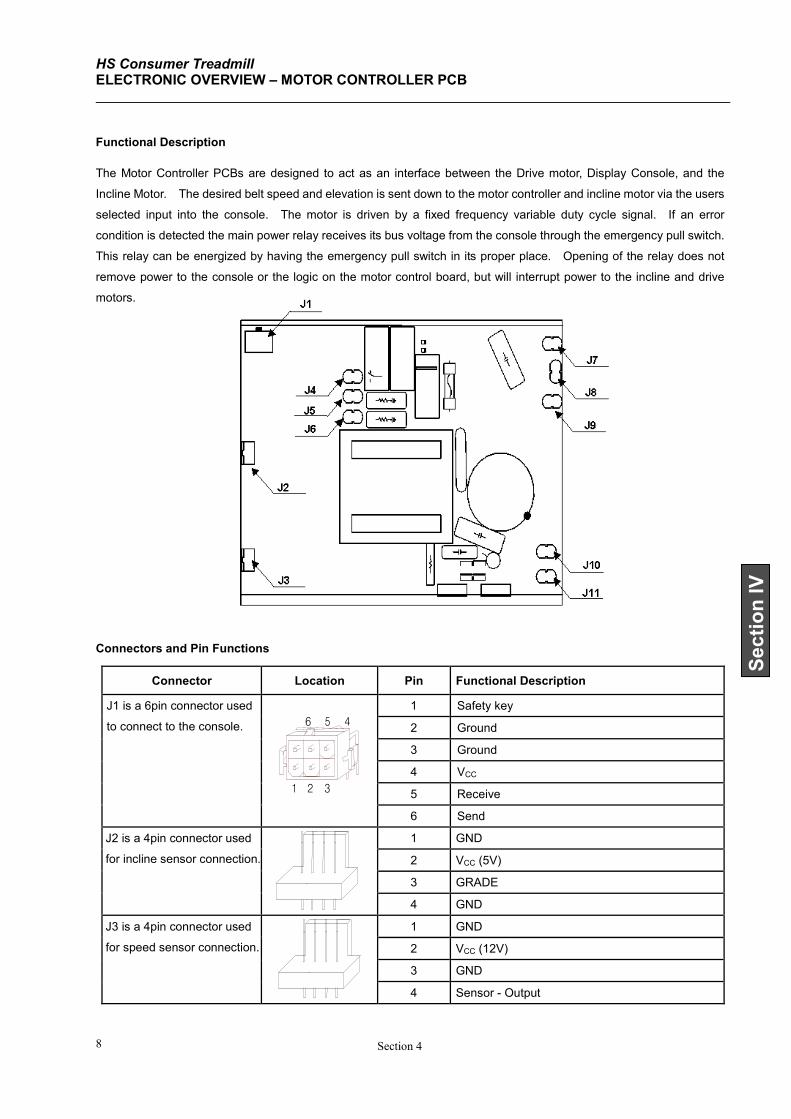
HS Consumer Treadmill ELECTRONIC OVERVIEW – MOTOR CONTROLLER PCB
Section 4 8
Section IV
1 2
5
3
6 4
Functional Description
The Motor Controller PCBs are designed to act as an interface between the Drive motor, Display Console, and the
Incline Motor. The desired belt speed and elevation is sent down to the motor controller and incline motor via the users
selected input into the console. The motor is driven by a fixed frequency variable duty cycle signal. If an error
condition is detected the main power relay receives its bus voltage from the console through the emergency pull switch.
This relay can be energized by having the emergency pull switch in its proper place. Opening of the relay does not
remove power to the console or the logic on the motor control board, but will interrupt power to the incline and drive
motors.
Connectors and Pin Functions
Connector Location Pin Functional Description
J1 is a 6pin connector used
to connect to the console.
1 Safety key
2 Ground
3 Ground
4 VCC
5 Receive
6 Send
J2 is a 4pin connector used
for incline sensor connection.
1 GND
2 VCC (5V)
3 GRADE
4 GND
J3 is a 4pin connector used
for speed sensor connection.
1 GND
2 VCC (12V)
3 GND
4 Sensor - Output
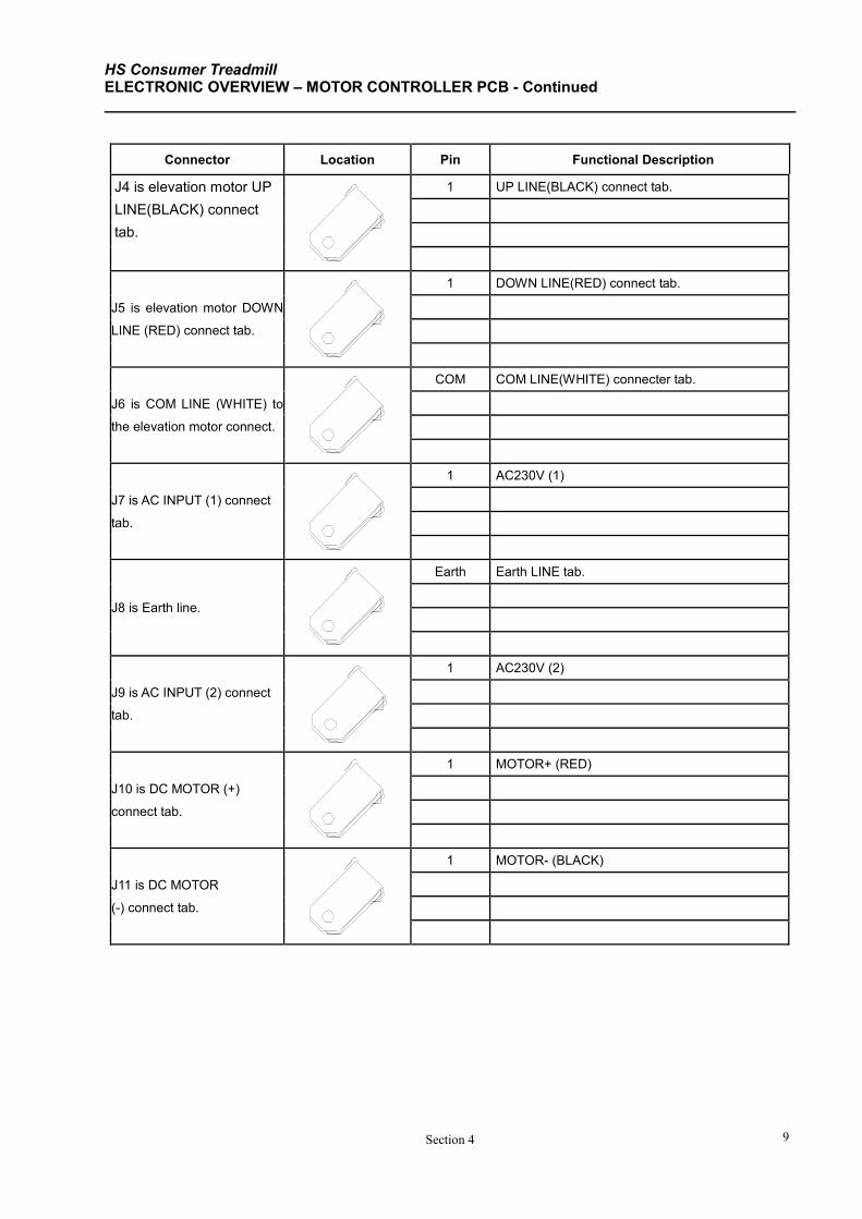
HS Consumer Treadmill ELECTRONIC OVERVIEW – MOTOR CONTROLLER PCB - Continued
Section 4 9
Connector Location Pin Functional Description
J4 is elevation motor UP
LINE(BLACK) connect
tab.
1 UP LINE(BLACK) connect tab.
J5 is elevation motor DOWN
LINE (RED) connect tab.
1 DOWN LINE(RED) connect tab.
J6 is COM LINE (WHITE) to
the elevation motor connect.
COM COM LINE(WHITE) connecter tab.
J7 is AC INPUT (1) connect
tab.
1 AC230V (1)
J8 is Earth line.
Earth Earth LINE tab.
J9 is AC INPUT (2) connect
tab.
1 AC230V (2)
J10 is DC MOTOR (+)
connect tab.
1 MOTOR+ (RED)
J11 is DC MOTOR
(-) connect tab.
1 MOTOR- (BLACK)
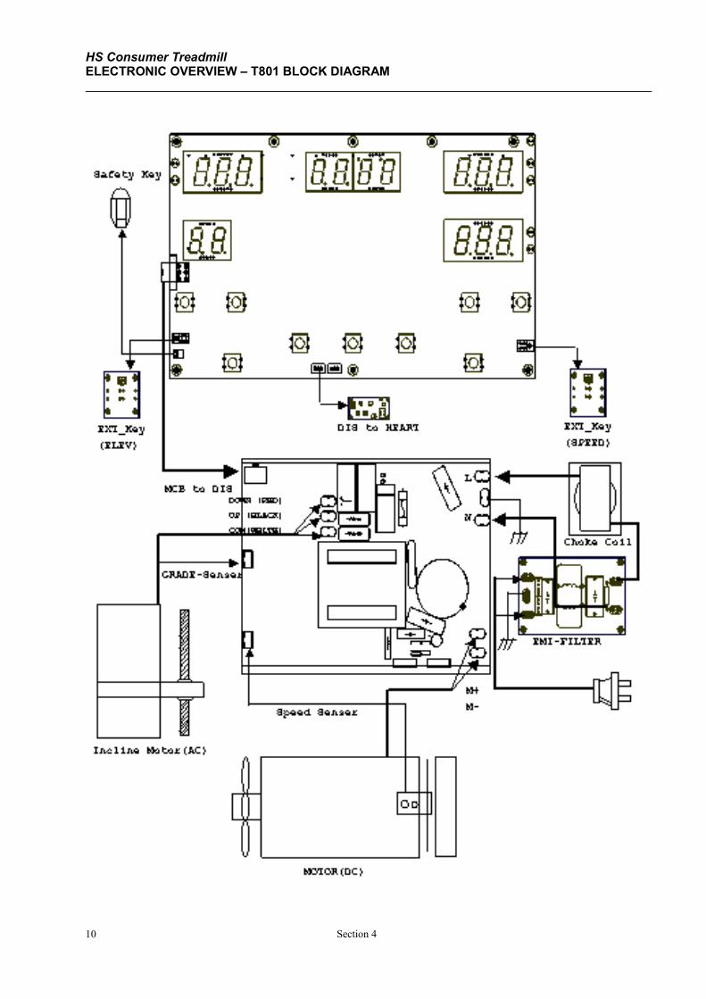
HS Consumer Treadmill ELECTRONIC OVERVIEW – T801 BLOCK DIAGRAM
Section 4 10
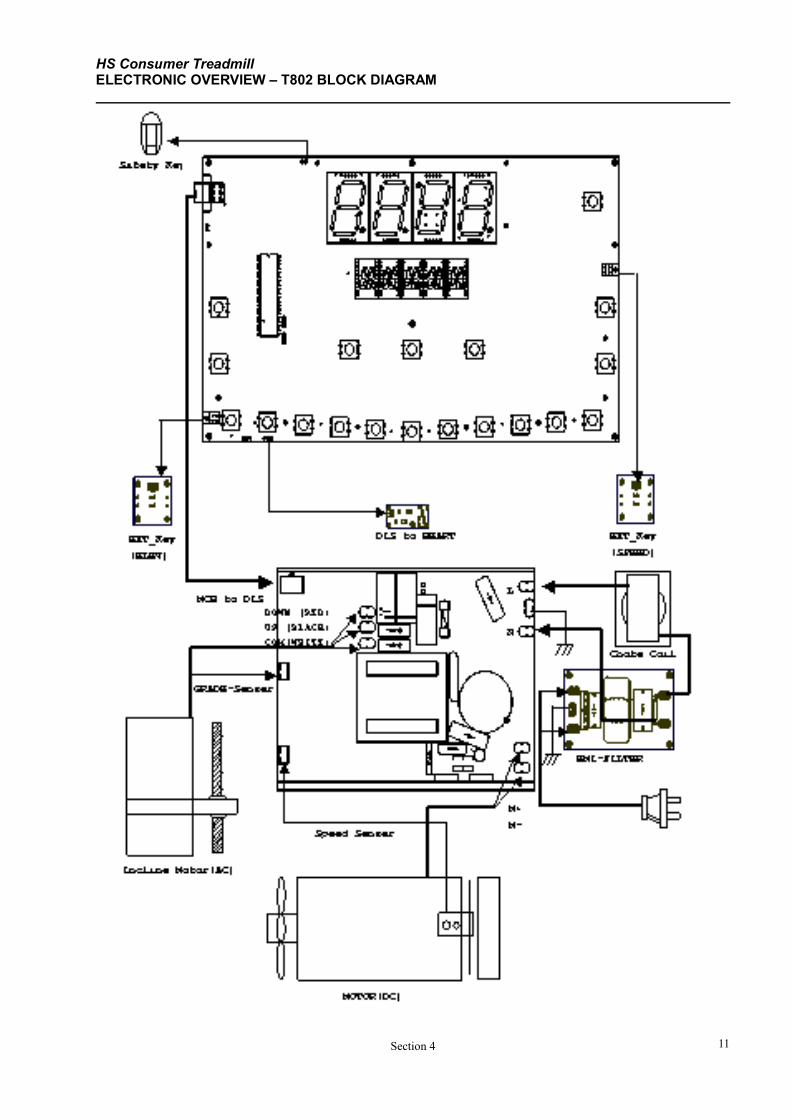
HS Consumer Treadmill ELECTRONIC OVERVIEW – T802 BLOCK DIAGRAM
Section 4 11
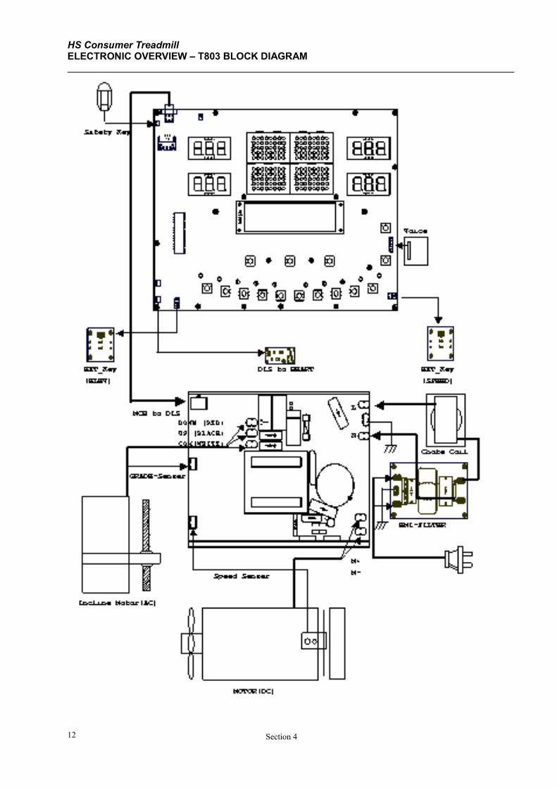
HS Consumer Treadmill ELECTRONIC OVERVIEW – T803 BLOCK DIAGRAM
Section 4 12
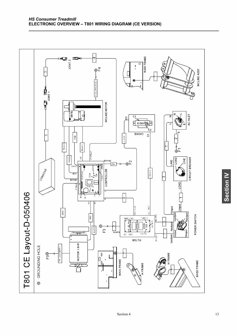
HS Consumer Treadmill ELECTRONIC OVERVIEW – T801 WIRING DIAGRAM (CE VERSION)
Section 4 13
Section IV
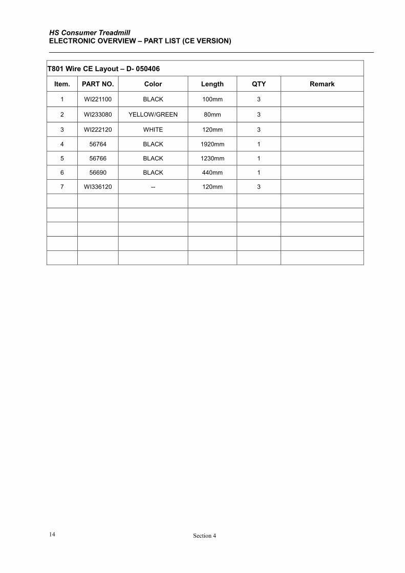
HS Consumer Treadmill ELECTRONIC OVERVIEW – PART LIST (CE VERSION)
Section 4 14
T801 Wire CE Layout – D- 050406
Item. PART NO. Color Length QTY Remark
1 WI221100 BLACK 100mm 3
2 WI233080 YELLOW/GREEN 80mm 3
3 WI222120 WHITE 120mm 3
4 56764 BLACK 1920mm 1
5 56766 BLACK 1230mm 1
6 56690 BLACK 440mm 1
7 WI336120 -- 120mm 3
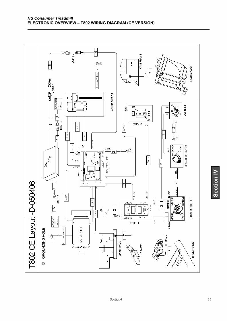
HS Consumer Treadmill ELECTRONIC OVERVIEW – T802 WIRING DIAGRAM (CE VERSION)
Section4 15
Section IV
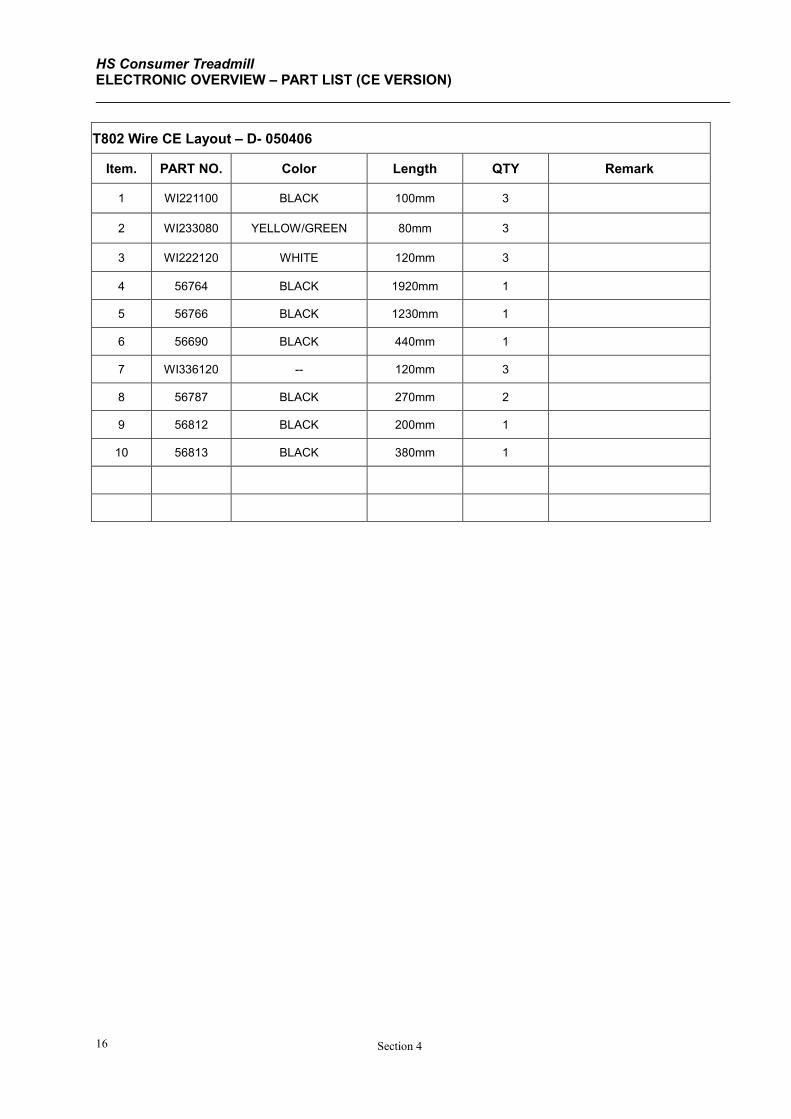
HS Consumer Treadmill ELECTRONIC OVERVIEW – PART LIST (CE VERSION)
Section 4 16
T802 Wire CE Layout – D- 050406
Item. PART NO. Color Length QTY Remark
1 WI221100 BLACK 100mm 3
2 WI233080 YELLOW/GREEN 80mm 3
3 WI222120 WHITE 120mm 3
4 56764 BLACK 1920mm 1
5 56766 BLACK 1230mm 1
6 56690 BLACK 440mm 1
7 WI336120 -- 120mm 3
8 56787 BLACK 270mm 2
9 56812 BLACK 200mm 1
10 56813 BLACK 380mm 1
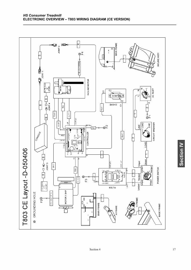
HS Consumer Treadmill ELECTRONIC OVERVIEW – T803 WIRING DIAGRAM (CE VERSION)
Section 4 17
Section IV
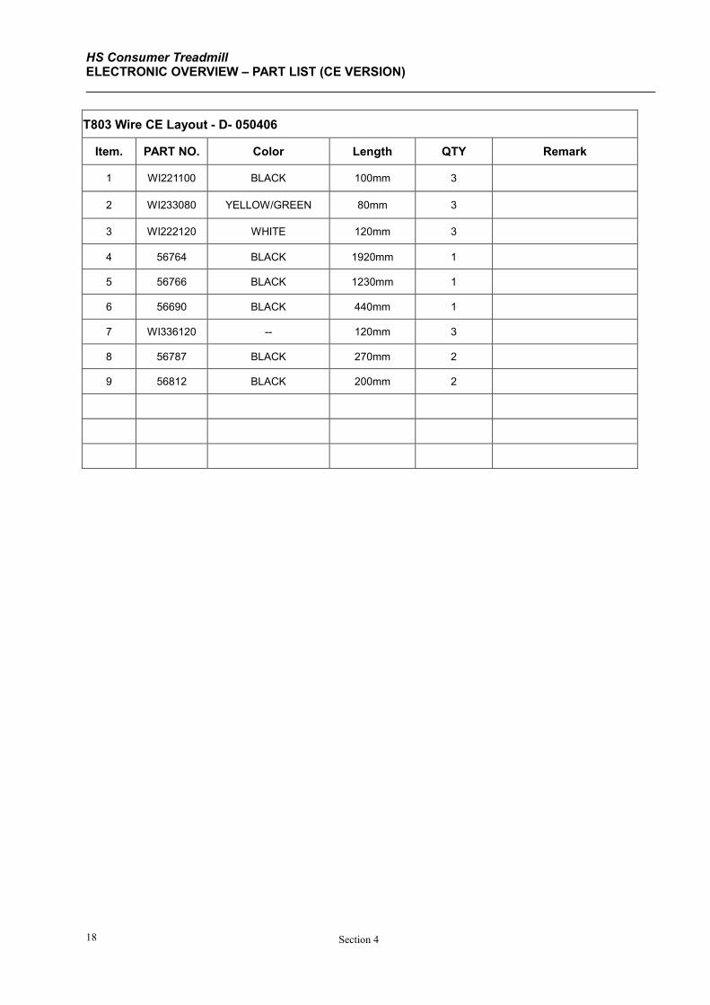
HS Consumer Treadmill ELECTRONIC OVERVIEW – PART LIST (CE VERSION)
Section 4 18
T803 Wire CE Layout - D- 050406
Item. PART NO. Color Length QTY Remark
1 WI221100 BLACK 100mm 3
2 WI233080 YELLOW/GREEN 80mm 3
3 WI222120 WHITE 120mm 3
4 56764 BLACK 1920mm 1
5 56766 BLACK 1230mm 1
6 56690 BLACK 440mm 1
7 WI336120 -- 120mm 3
8 56787 BLACK 270mm 2
9 56812 BLACK 200mm 2

HS Consumer Treadmill
Section 5 1
Section V
SECTION V
PARTS IDENTIFICATION
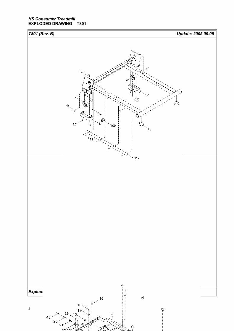
HS Consumer Treadmill EXPLODED DRAWING – T801
Section 5 2
T801 (Rev. B) Update: 2005.09.05
Explode drawing & part list 050905
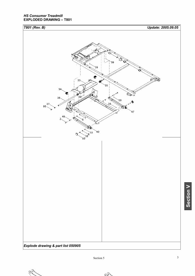
HS Consumer Treadmill EXPLODED DRAWING – T801
Section 5 3
Section V
T801 (Rev. B) Update: 2005.09.05
Explode drawing & part list 050905
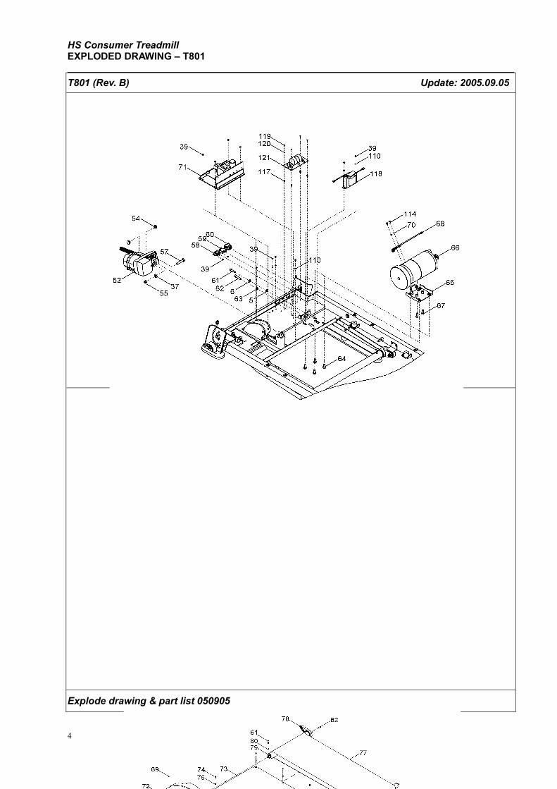
HS Consumer Treadmill EXPLODED DRAWING – T801
Section 5 4
T801 (Rev. B) Update: 2005.09.05
Explode drawing & part list 050905
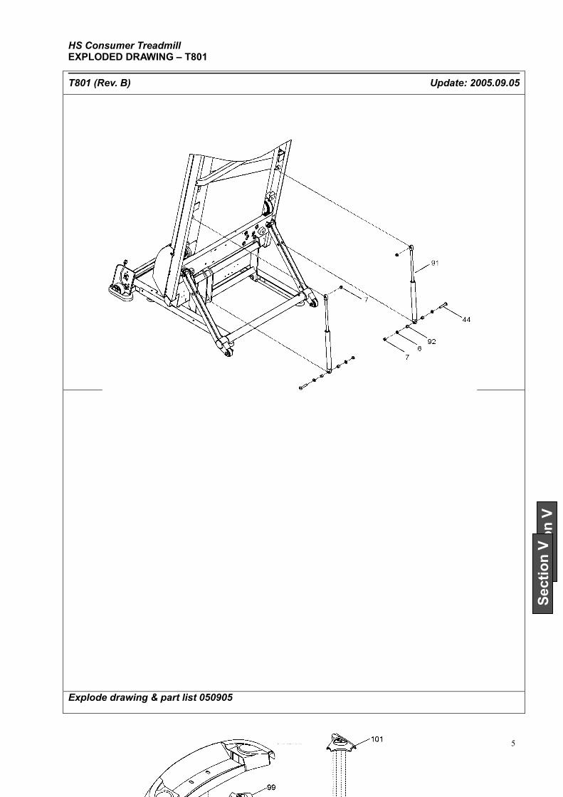
HS Consumer Treadmill EXPLODED DRAWING – T801
Section 5
Section V
Section V
T801 (Rev. B) Update: 2005.09.05
Explode drawing & part list 050905
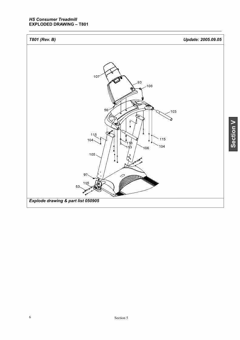
HS Consumer Treadmill EXPLODED DRAWING – T801
Section 5 6
Section V
T801 (Rev. B) Update: 2005.09.05
Explode drawing & part list 050905
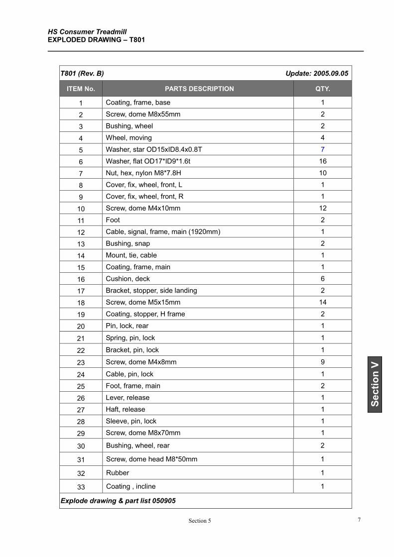
HS Consumer Treadmill EXPLODED DRAWING – T801
Section 5 7
Section V
T801 (Rev. B) Update: 2005.09.05
ITEM No. PARTS DESCRIPTION QTY.
1 Coating, frame, base 1
2 Screw, dome M8x55mm 2
3 Bushing, wheel 2
4 Wheel, moving 4
5 Washer, star OD15xID8.4x0.8T 7
6 Washer, flat OD17*ID9*1.6t 16
7 Nut, hex, nylon M8*7.8H 10
8 Cover, fix, wheel, front, L 1
9 Cover, fix, wheel, front, R 1
10 Screw, dome M4x10mm 12
11 Foot 2
12 Cable, signal, frame, main (1920mm) 1
13 Bushing, snap 2
14 Mount, tie, cable 1
15 Coating, frame, main 1
16 Cushion, deck 6
17 Bracket, stopper, side landing 2
18 Screw, dome M5x15mm 14
19 Coating, stopper, H frame 2
20 Pin, lock, rear 1
21 Spring, pin, lock 1
22 Bracket, pin, lock 1
23 Screw, dome M4x8mm 9
24 Cable, pin, lock 1
25 Foot, frame, main 2
26 Lever, release 1
27 Haft, release 1
28 Sleeve, pin, lock 1
29 Screw, dome M8x70mm 1
30 Bushing, wheel, rear 2
31 Screw, dome head M8*50mm 1
32 Rubber 1
33 Coating , incline 1
Explode drawing & part list 050905
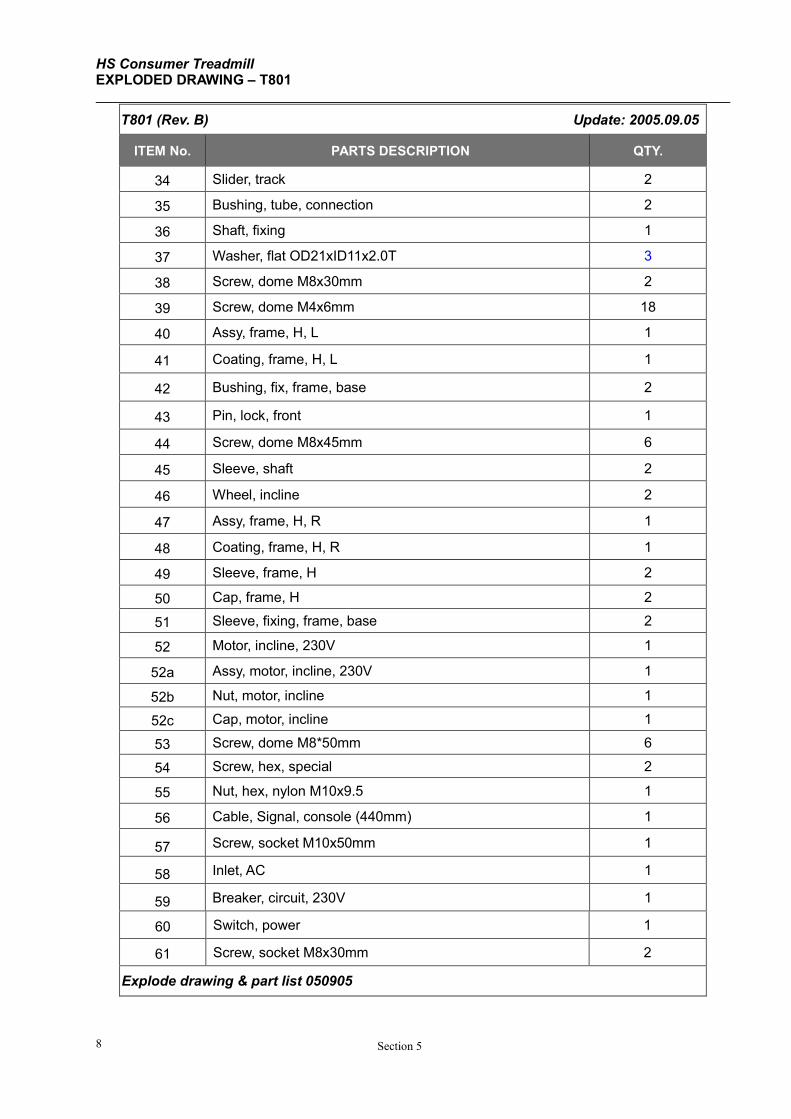
HS Consumer Treadmill EXPLODED DRAWING – T801
Section 5 8
T801 (Rev. B) Update: 2005.09.05
ITEM No. PARTS DESCRIPTION QTY.
34 Slider, track 2
35 Bushing, tube, connection 2
36 Shaft, fixing 1
37 Washer, flat OD21xID11x2.0T 3
38 Screw, dome M8x30mm 2
39 Screw, dome M4x6mm 18
40 Assy, frame, H, L 1
41 Coating, frame, H, L 1
42 Bushing, fix, frame, base 2
43 Pin, lock, front 1
44 Screw, dome M8x45mm 6
45 Sleeve, shaft 2
46 Wheel, incline 2
47 Assy, frame, H, R 1
48 Coating, frame, H, R 1
49 Sleeve, frame, H 2
50 Cap, frame, H 2
51 Sleeve, fixing, frame, base 2
52 Motor, incline, 230V 1
52a Assy, motor, incline, 230V 1
52b Nut, motor, incline 1
52c Cap, motor, incline 1
53 Screw, dome M8*50mm 6
54 Screw, hex, special 2
55 Nut, hex, nylon M10x9.5 1
56 Cable, Signal, console (440mm) 1
57 Screw, socket M10x50mm 1
58 Inlet, AC 1
59 Breaker, circuit, 230V 1
60 Switch, power 1
61 Screw, socket M8x30mm 2
Explode drawing & part list 050905
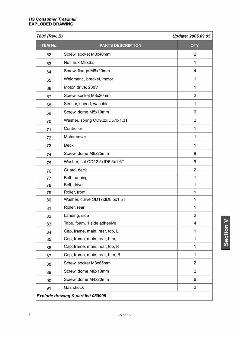
HS Consumer Treadmill EXPLODED DRAWING
Section 5 8
Section V
T801 (Rev. B) Update: 2005.09.05
ITEM No. PARTS DESCRIPTION QTY.
62 Screw, socket M8x40mm 2
63 Nut, hex M8x6.5 1
64 Screw, flange M8x20mm 4
65 Weldment , bracket, motor 1
66 Motor, drive, 230V 1
67 Screw, socket M8x20mm 2
68 Sensor, speed, w/ cable 1
69 Screw, dome M5x10mm 6
70 Washer, spring OD9.2xID5.1x1.3T 2
71 Controller 1
72 Motor cover 1
73 Deck 1
74 Screw, dome M6x25mm 8
75 Washer, flat OD12.5xID6.6x1.6T 9
76 Guard, deck 2
77 Belt, running 1
78 Belt, drive 1
79 Roller, front 1
80 Washer, curve OD17xID8.5x1.5T 1
81 Roller, rear 1
82 Landing, side 2
83 Tape, foam, 1 side adhesive 4
84 Cap, frame, main, rear, top, L 1
85 Cap, frame, main, rear, btm, L 1
86 Cap, frame, main, rear, top, R 1
87 Cap, frame, main, rear, btm, R 1
88 Screw, socket M8x65mm 2
89 Screw, dome M6x10mm 2
90 Screw, dome M4x20mm 6
91 Gas shock 2
Explode drawing & part list 050905
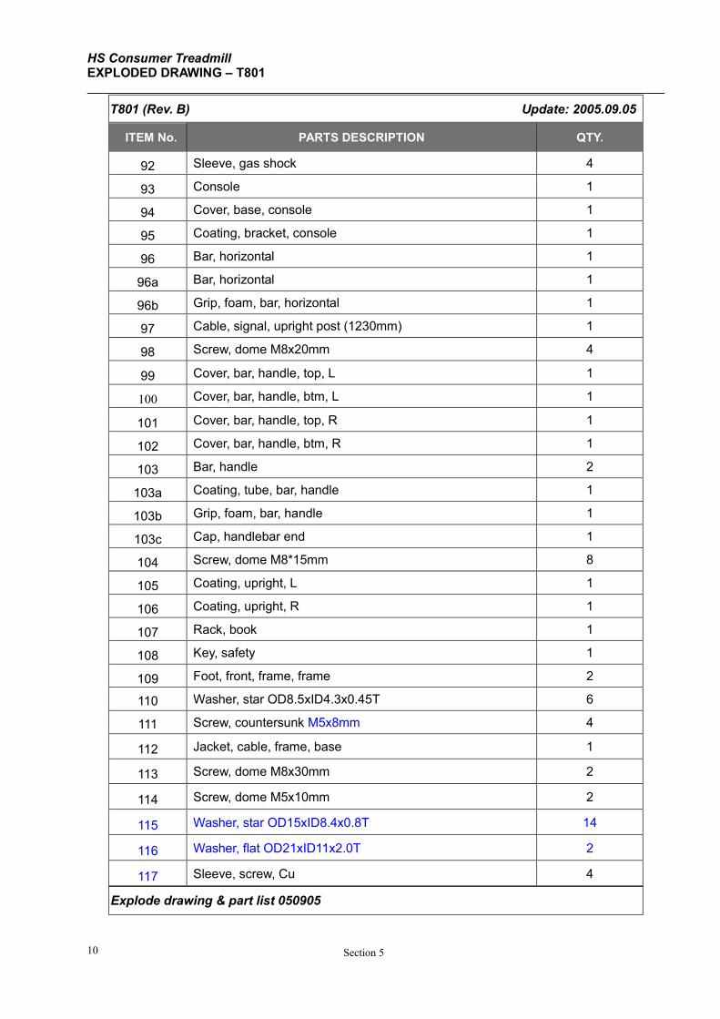
HS Consumer Treadmill EXPLODED DRAWING – T801
Section 5 10
T801 (Rev. B) Update: 2005.09.05
ITEM No. PARTS DESCRIPTION QTY.
92 Sleeve, gas shock 4
93 Console 1
94 Cover, base, console 1
95 Coating, bracket, console 1
96 Bar, horizontal 1
96a Bar, horizontal 1
96b Grip, foam, bar, horizontal 1
97 Cable, signal, upright post (1230mm) 1
98 Screw, dome M8x20mm 4
99 Cover, bar, handle, top, L 1
100 Cover, bar, handle, btm, L 1
101 Cover, bar, handle, top, R 1
102 Cover, bar, handle, btm, R 1
103 Bar, handle 2
103a Coating, tube, bar, handle 1
103b Grip, foam, bar, handle 1
103c Cap, handlebar end 1
104 Screw, dome M8*15mm 8
105 Coating, upright, L 1
106 Coating, upright, R 1
107 Rack, book 1
108 Key, safety 1
109 Foot, front, frame, frame 2
110 Washer, star OD8.5xID4.3x0.45T 6
111 Screw, countersunk M5x8mm 4
112 Jacket, cable, frame, base 1
113 Screw, dome M8x30mm 2
114 Screw, dome M5x10mm 2
115 Washer, star OD15xID8.4x0.8T 14
116 Washer, flat OD21xID11x2.0T 2
117 Sleeve, screw, Cu 4
Explode drawing & part list 050905

HS Consumer Treadmill EXPLODED DRAWING
Section 5 10
T801 (Rev. D) Update: 2005.09.05
ITEM No. PARTS DESCRIPTION QTY.
118 Choke 1
119 Screw, Phillips M3x6mm 4
120 Washer, spring OD5xID3.3x0.8T 4
121 Filter 1
Explode drawing & part list 050905
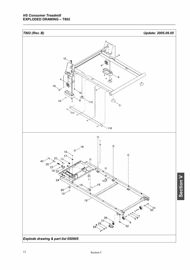
HS Consumer Treadmill EXPLODED DRAWING – T802
Section 5 12
Section V
T802 (Rev. B) Update: 2005.09.05
Explode drawing & part list 050905
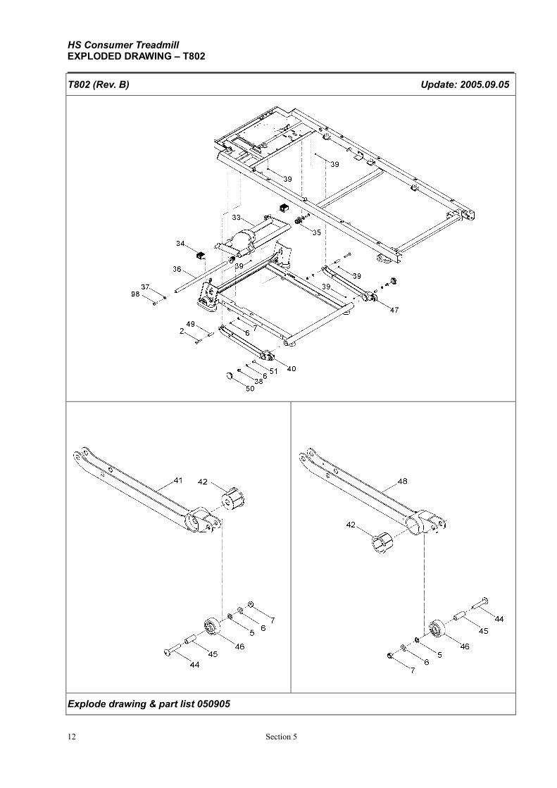
HS Consumer Treadmill EXPLODED DRAWING – T802
12 Section 5
T802 (Rev. B) Update: 2005.09.05
Explode drawing & part list 050905
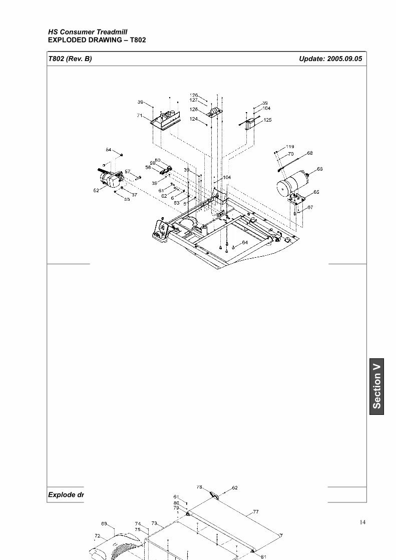
HS Consumer Treadmill EXPLODED DRAWING – T802
Section 5 14
Section V
T802 (Rev. B) Update: 2005.09.05
Explode drawing & part list 050905
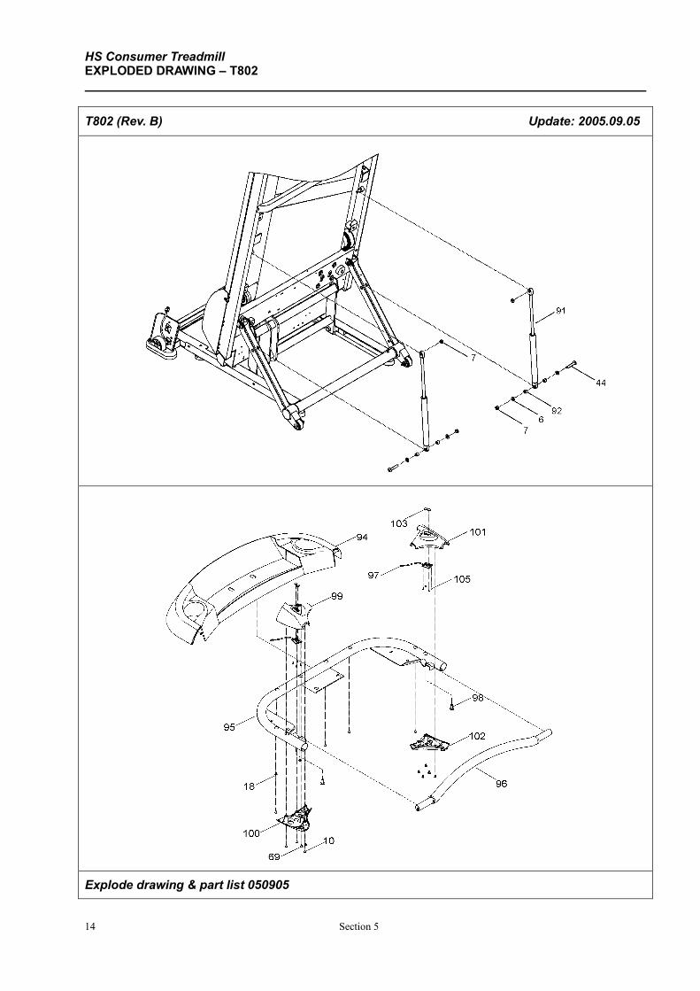
HS Consumer Treadmill EXPLODED DRAWING – T802
14 Section 5
T802 (Rev. B) Update: 2005.09.05
Explode drawing & part list 050905
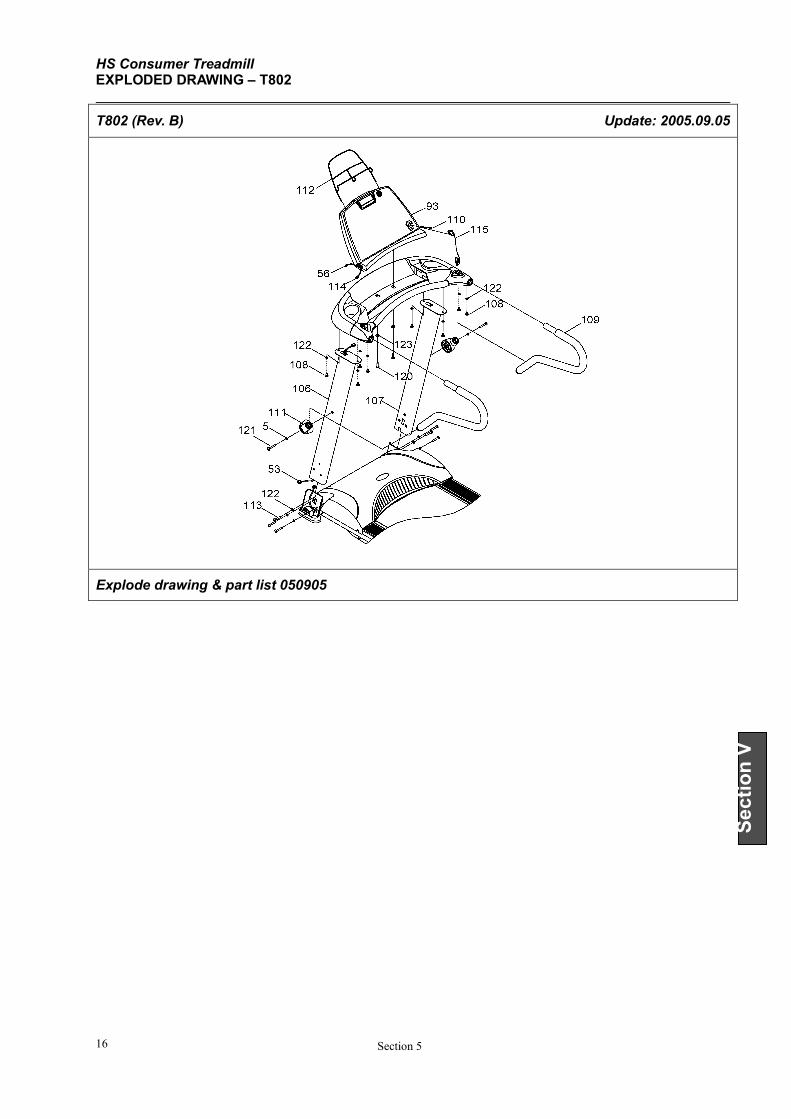
HS Consumer Treadmill EXPLODED DRAWING – T802
Section 5 16
Section V
T802 (Rev. B) Update: 2005.09.05
Explode drawing & part list 050905
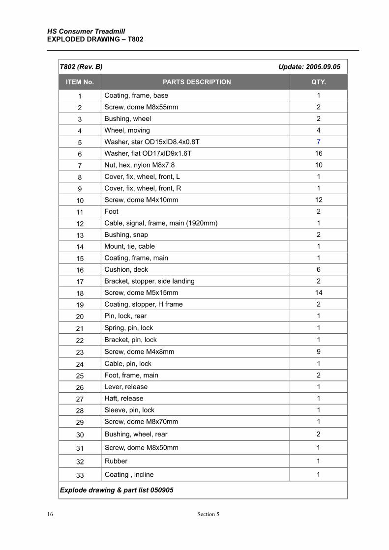
HS Consumer Treadmill EXPLODED DRAWING – T802
16 Section 5
T802 (Rev. B) Update: 2005.09.05
ITEM No. PARTS DESCRIPTION QTY.
1 Coating, frame, base 1
2 Screw, dome M8x55mm 2
3 Bushing, wheel 2
4 Wheel, moving 4
5 Washer, star OD15xID8.4x0.8T 7
6 Washer, flat OD17xID9x1.6T 16
7 Nut, hex, nylon M8x7.8 10
8 Cover, fix, wheel, front, L 1
9 Cover, fix, wheel, front, R 1
10 Screw, dome M4x10mm 12
11 Foot 2
12 Cable, signal, frame, main (1920mm) 1
13 Bushing, snap 2
14 Mount, tie, cable 1
15 Coating, frame, main 1
16 Cushion, deck 6
17 Bracket, stopper, side landing 2
18 Screw, dome M5x15mm 14
19 Coating, stopper, H frame 2
20 Pin, lock, rear 1
21 Spring, pin, lock 1
22 Bracket, pin, lock 1
23 Screw, dome M4x8mm 9
24 Cable, pin, lock 1
25 Foot, frame, main 2
26 Lever, release 1
27 Haft, release 1
28 Sleeve, pin, lock 1
29 Screw, dome M8x70mm 1
30 Bushing, wheel, rear 2
31 Screw, dome M8x50mm 1
32 Rubber 1
33 Coating , incline 1
Explode drawing & part list 050905
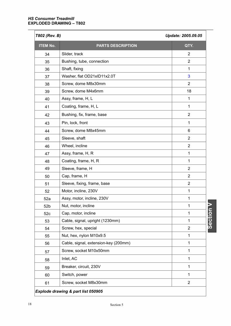
HS Consumer Treadmill EXPLODED DRAWING – T802
Section 5 18
Section V
T802 (Rev. B) Update: 2005.09.05
ITEM No. PARTS DESCRIPTION QTY.
34 Slider, track 2
35 Bushing, tube, connection 2
36 Shaft, fixing 1
37 Washer, flat OD21xID11x2.0T 3
38 Screw, dome M8x30mm 2
39 Screw, dome M4x6mm 18
40 Assy, frame, H, L 1
41 Coating, frame, H, L 1
42 Bushing, fix, frame, base 2
43 Pin, lock, front 1
44 Screw, dome M8x45mm 6
45 Sleeve, shaft 2
46 Wheel, incline 2
47 Assy, frame, H, R 1
48 Coating, frame, H, R 1
49 Sleeve, frame, H 2
50 Cap, frame, H 2
51 Sleeve, fixing, frame, base 2
52 Motor, incline, 230V 1
52a Assy, motor, incline, 230V 1
52b Nut, motor, incline 1
52c Cap, motor, incline 1
53 Cable, signal, upright (1230mm) 1
54 Screw, hex, special 2
55 Nut, hex, nylon M10x9.5 1
56 Cable, signal, extension-key (200mm) 1
57 Screw, socket M10x50mm 1
58 Inlet, AC 1
59 Breaker, circuit, 230V 1
60 Switch, power 1
61 Screw, socket M8x30mm 2
Explode drawing & part list 050905
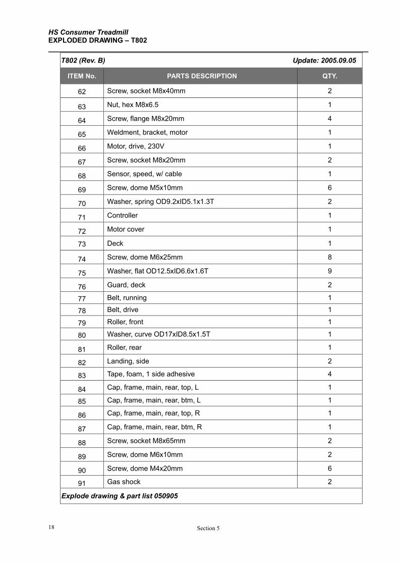
HS Consumer Treadmill EXPLODED DRAWING – T802
Section 5 18
T802 (Rev. B) Update: 2005.09.05
ITEM No. PARTS DESCRIPTION QTY.
62 Screw, socket M8x40mm 2
63 Nut, hex M8x6.5 1
64 Screw, flange M8x20mm 4
65 Weldment, bracket, motor 1
66 Motor, drive, 230V 1
67 Screw, socket M8x20mm 2
68 Sensor, speed, w/ cable 1
69 Screw, dome M5x10mm 6
70 Washer, spring OD9.2xID5.1x1.3T 2
71 Controller 1
72 Motor cover 1
73 Deck 1
74 Screw, dome M6x25mm 8
75 Washer, flat OD12.5xID6.6x1.6T 9
76 Guard, deck 2
77 Belt, running 1
78 Belt, drive 1
79 Roller, front 1
80 Washer, curve OD17xID8.5x1.5T 1
81 Roller, rear 1
82 Landing, side 2
83 Tape, foam, 1 side adhesive 4
84 Cap, frame, main, rear, top, L 1
85 Cap, frame, main, rear, btm, L 1
86 Cap, frame, main, rear, top, R 1
87 Cap, frame, main, rear, btm, R 1
88 Screw, socket M8x65mm 2
89 Screw, dome M6x10mm 2
90 Screw, dome M4x20mm 6
91 Gas shock 2
Explode drawing & part list 050905
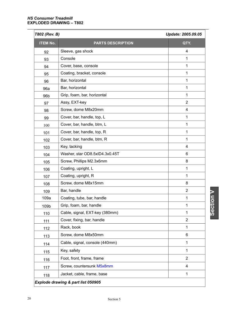
HS Consumer Treadmill EXPLODED DRAWING – T802
Section 5 20
Section V
T802 (Rev. B) Update: 2005.09.05
ITEM No. PARTS DESCRIPTION QTY.
92 Sleeve, gas shock 4
93 Console 1
94 Cover, base, console 1
95 Coating, bracket, console 1
96 Bar, horizontal 1
96a Bar, horizontal 1
96b Grip, foam, bar, horizontal 1
97 Assy, EXT-key 2
98 Screw, dome M8x20mm 4
99 Cover, bar, handle, top, L 1
100 Cover, bar, handle, btm, L 1
101 Cover, bar, handle, top, R 1
102 Cover, bar, handle, btm, R 1
103 Key, tacking 4
104 Washer, star OD8.5xID4.3x0.45T 6
105 Screw, Phillips M2.3x6mm 8
106 Coating, upright, L 1
107 Coating, upright, R 1
108 Screw, dome M8x15mm 8
109 Bar, handle 2
109a Coating, tube, bar, handle 1
109b Grip, foam, bar, handle 1
110 Cable, signal, EXT-key (380mm) 1
111 Cover, fixing, bar, handle 2
112 Rack, book 1
113 Screw, dome M8x50mm 6
114 Cable, signal, console (440mm) 1
115 Key, safety 1
116 Foot, front, frame, frame 2
117 Screw, countersunk M5x8mm 4
118 Jacket, cable, frame, base 1
Explode drawing & part list 050905
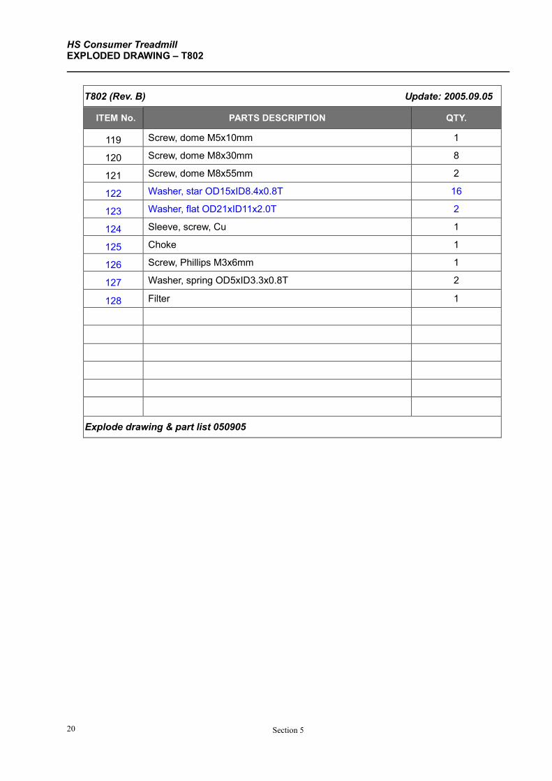
HS Consumer Treadmill EXPLODED DRAWING – T802
Section 5 20
T802 (Rev. B) Update: 2005.09.05
ITEM No. PARTS DESCRIPTION QTY.
119 Screw, dome M5x10mm 1
120 Screw, dome M8x30mm 8
121 Screw, dome M8x55mm 2
122 Washer, star OD15xID8.4x0.8T 16
123 Washer, flat OD21xID11x2.0T 2
124 Sleeve, screw, Cu 1
125 Choke 1
126 Screw, Phillips M3x6mm 1
127 Washer, spring OD5xID3.3x0.8T 2
128 Filter 1
Explode drawing & part list 050905
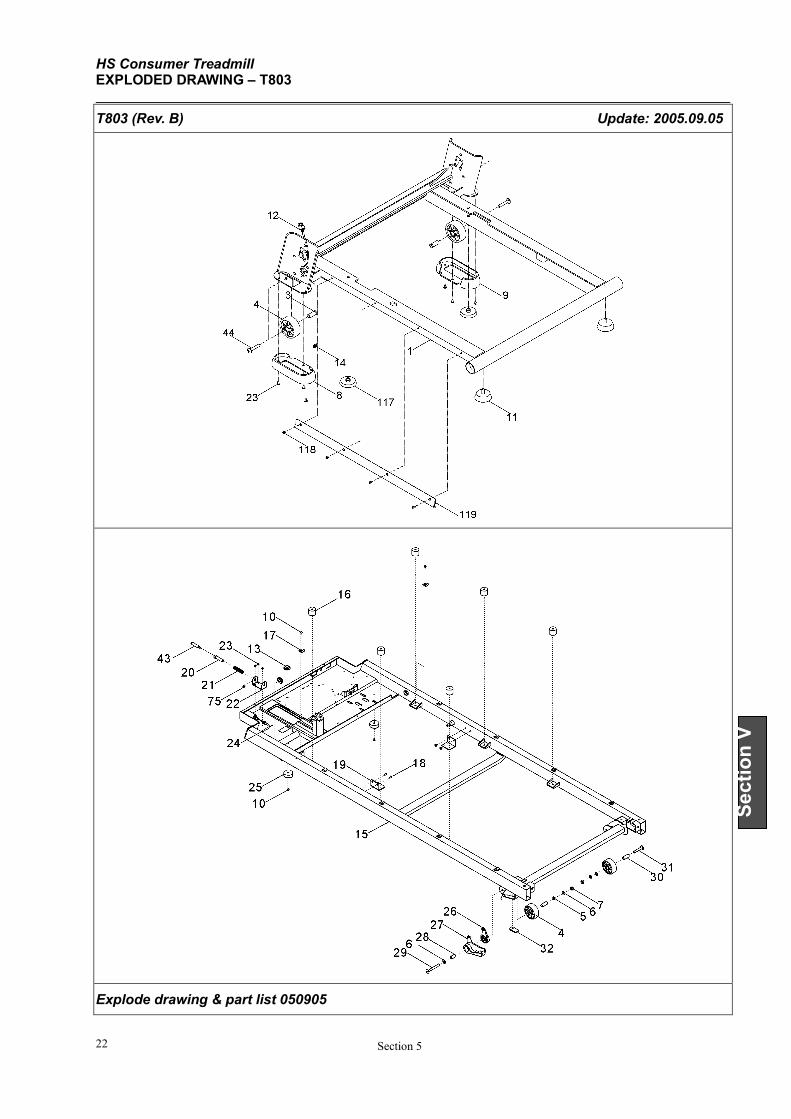
HS Consumer Treadmill EXPLODED DRAWING – T803
Section 5 22
Section V
T803 (Rev. B) Update: 2005.09.05
Explode drawing & part list 050905
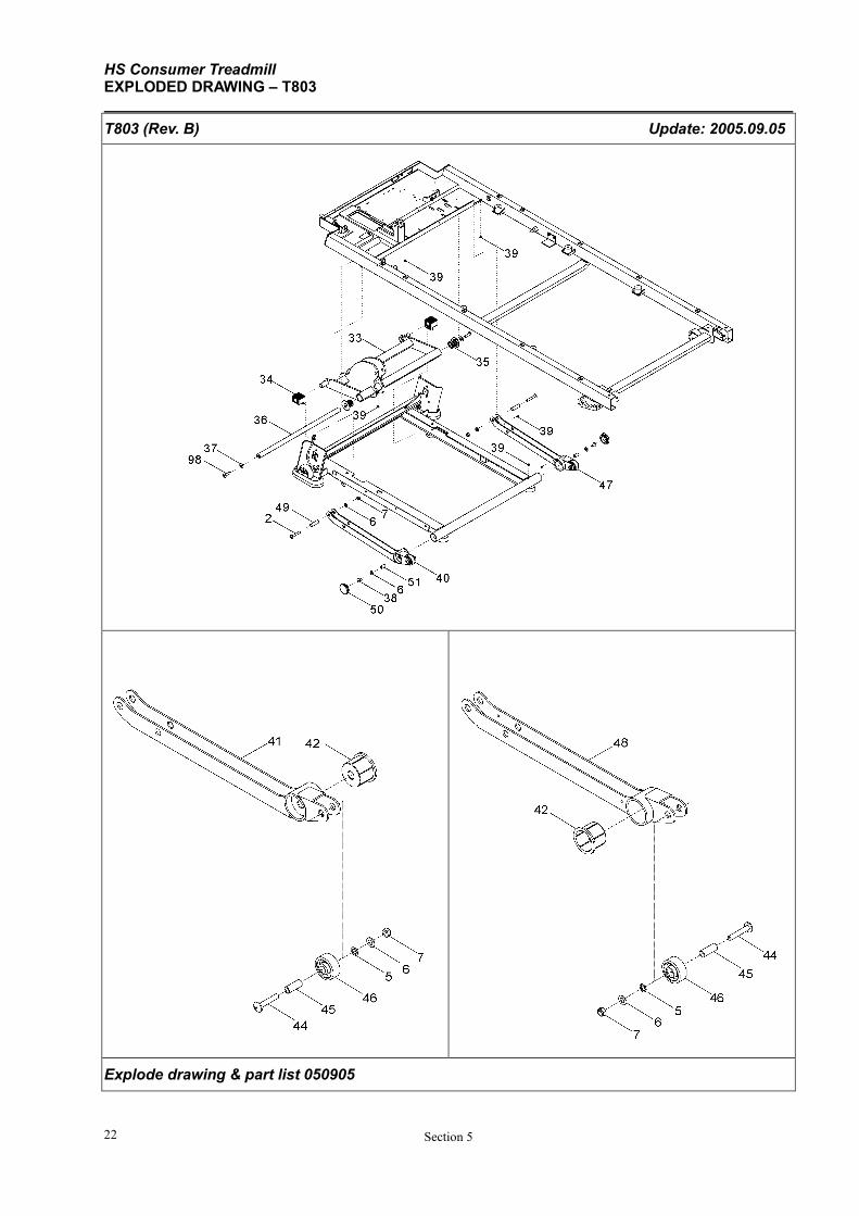
HS Consumer Treadmill EXPLODED DRAWING – T803
Section 5 22
T803 (Rev. B) Update: 2005.09.05
Explode drawing & part list 050905
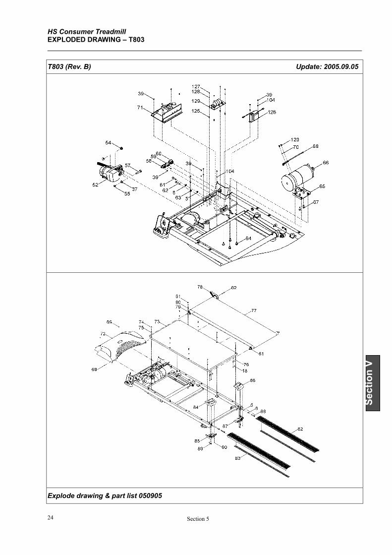
HS Consumer Treadmill EXPLODED DRAWING – T803
Section 5 24
Section V
T803 (Rev. B) Update: 2005.09.05
Explode drawing & part list 050905
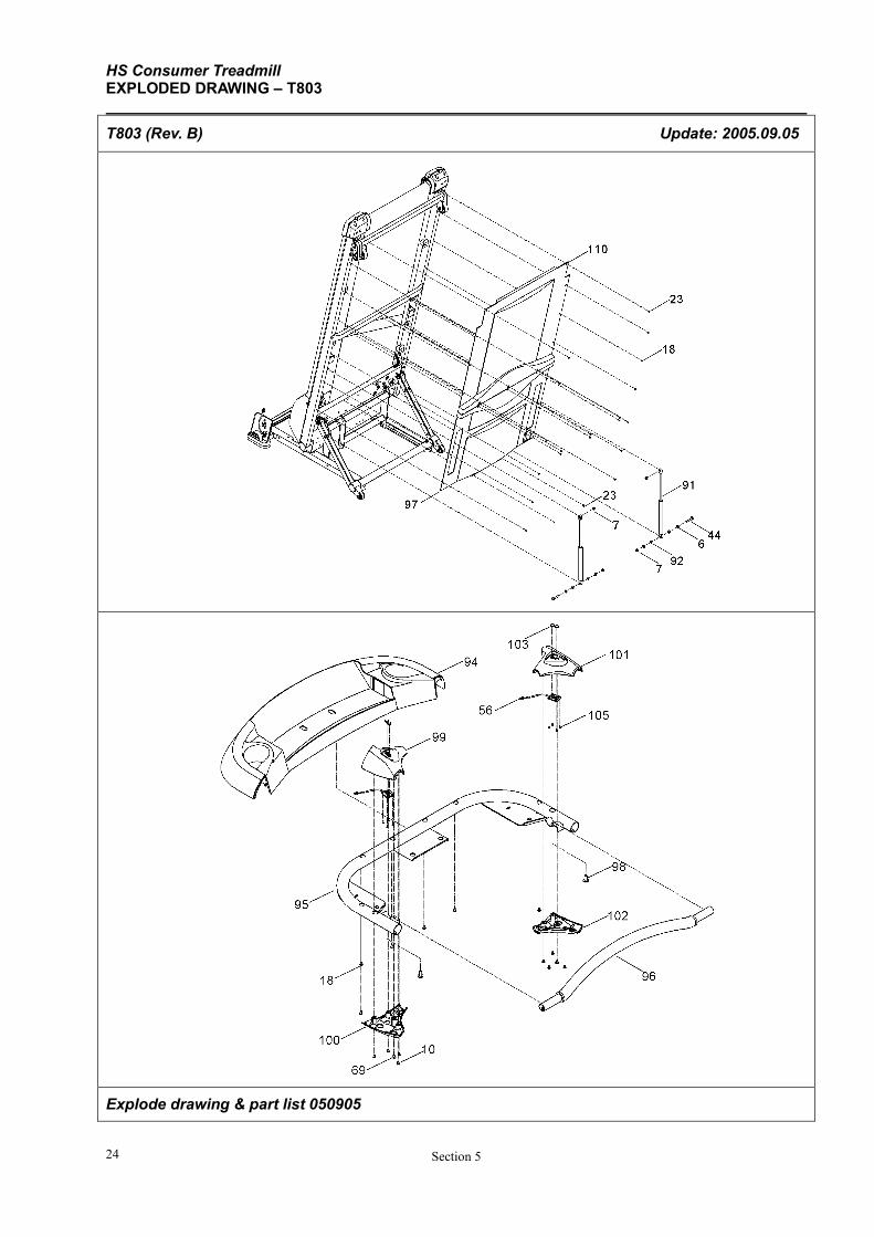
HS Consumer Treadmill EXPLODED DRAWING – T803
Section 5 24
T803 (Rev. B) Update: 2005.09.05
Explode drawing & part list 050905

HS Consumer Treadmill EXPLODED DRAWING – T803
Section 5 26
Section V
T803 (Rev. B) Update: 2005.09.05
Explode drawing & part list 050905
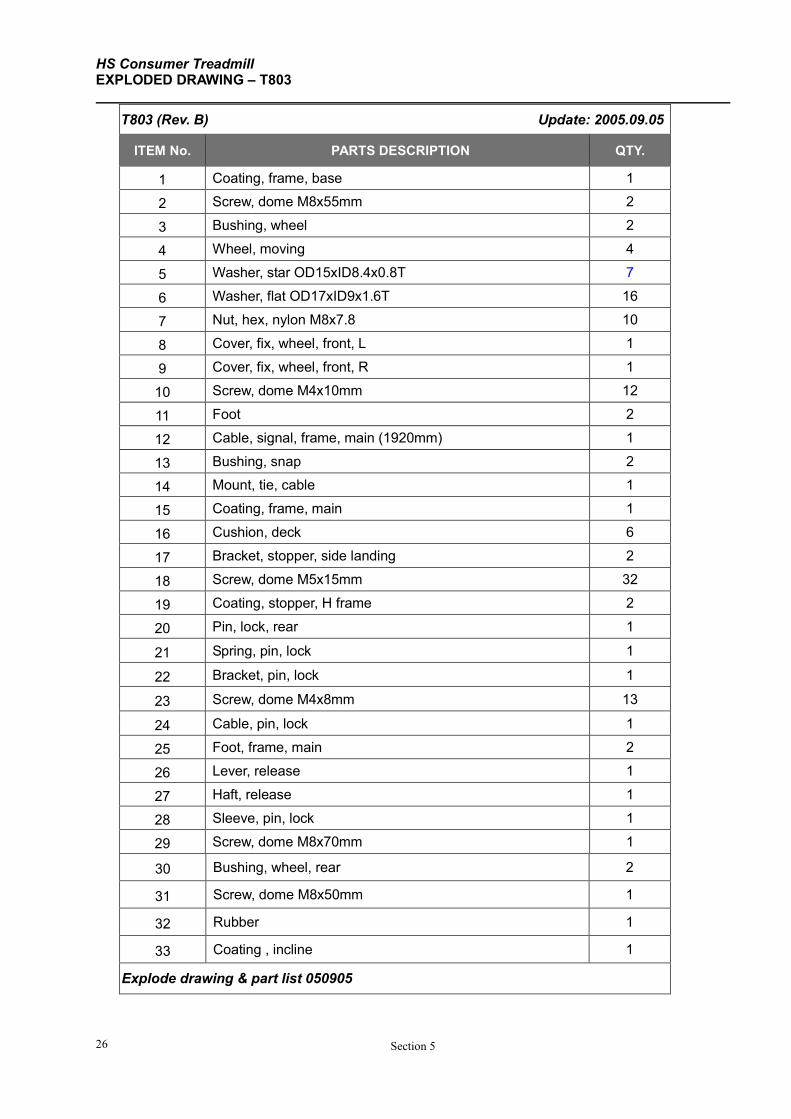
HS Consumer Treadmill EXPLODED DRAWING – T803
Section 5 26
T803 (Rev. B) Update: 2005.09.05
ITEM No. PARTS DESCRIPTION QTY.
1 Coating, frame, base 1
2 Screw, dome M8x55mm 2
3 Bushing, wheel 2
4 Wheel, moving 4
5 Washer, star OD15xID8.4x0.8T 7
6 Washer, flat OD17xID9x1.6T 16
7 Nut, hex, nylon M8x7.8 10
8 Cover, fix, wheel, front, L 1
9 Cover, fix, wheel, front, R 1
10 Screw, dome M4x10mm 12
11 Foot 2
12 Cable, signal, frame, main (1920mm) 1
13 Bushing, snap 2
14 Mount, tie, cable 1
15 Coating, frame, main 1
16 Cushion, deck 6
17 Bracket, stopper, side landing 2
18 Screw, dome M5x15mm 32
19 Coating, stopper, H frame 2
20 Pin, lock, rear 1
21 Spring, pin, lock 1
22 Bracket, pin, lock 1
23 Screw, dome M4x8mm 13
24 Cable, pin, lock 1
25 Foot, frame, main 2
26 Lever, release 1
27 Haft, release 1
28 Sleeve, pin, lock 1
29 Screw, dome M8x70mm 1
30 Bushing, wheel, rear 2
31 Screw, dome M8x50mm 1
32 Rubber 1
33 Coating , incline 1
Explode drawing & part list 050905
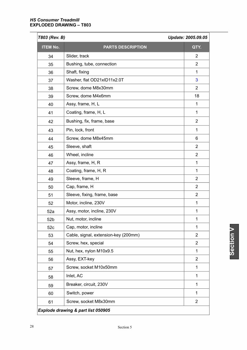
HS Consumer Treadmill EXPLODED DRAWING – T803
Section 5 28
Section V
T803 (Rev. B) Update: 2005.09.05
ITEM No. PARTS DESCRIPTION QTY.
34 Slider, track 2
35 Bushing, tube, connection 2
36 Shaft, fixing 1
37 Washer, flat OD21xID11x2.0T 3
38 Screw, dome M8x30mm 2
39 Screw, dome M4x6mm 18
40 Assy, frame, H, L 1
41 Coating, frame, H, L 1
42 Bushing, fix, frame, base 2
43 Pin, lock, front 1
44 Screw, dome M8x45mm 6
45 Sleeve, shaft 2
46 Wheel, incline 2
47 Assy, frame, H, R 1
48 Coating, frame, H, R 1
49 Sleeve, frame, H 2
50 Cap, frame, H 2
51 Sleeve, fixing, frame, base 2
52 Motor, incline, 230V 1
52a Assy, motor, incline, 230V 1
52b Nut, motor, incline 1
52c Cap, motor, incline 1
53 Cable, signal, extension-key (200mm) 2
54 Screw, hex, special 2
55 Nut, hex, nylon M10x9.5 1
56 Assy, EXT-key 2
57 Screw, socket M10x50mm 1
58 Inlet, AC 1
59 Breaker, circuit, 230V 1
60 Switch, power 1
61 Screw, socket M8x30mm 2
Explode drawing & part list 050905
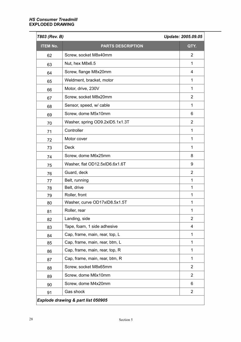
HS Consumer Treadmill EXPLODED DRAWING
Section 5 28
T803 (Rev. B) Update: 2005.09.05
ITEM No. PARTS DESCRIPTION QTY.
62 Screw, socket M8x40mm 2
63 Nut, hex M8x6.5 1
64 Screw, flange M8x20mm 4
65 Weldment, bracket, motor 1
66 Motor, drive, 230V 1
67 Screw, socket M8x20mm 2
68 Sensor, speed, w/ cable 1
69 Screw, dome M5x10mm 6
70 Washer, spring OD9.2xID5.1x1.3T 2
71 Controller 1
72 Motor cover 1
73 Deck 1
74 Screw, dome M6x25mm 8
75 Washer, flat OD12.5xID6.6x1.6T 9
76 Guard, deck 2
77 Belt, running 1
78 Belt, drive 1
79 Roller, front 1
80 Washer, curve OD17xID8.5x1.5T 1
81 Roller, rear 1
82 Landing, side 2
83 Tape, foam, 1 side adhesive 4
84 Cap, frame, main, rear, top, L 1
85 Cap, frame, main, rear, btm, L 1
86 Cap, frame, main, rear, top, R 1
87 Cap, frame, main, rear, btm, R 1
88 Screw, socket M8x65mm 2
89 Screw, dome M6x10mm 2
90 Screw, dome M4x20mm 6
91 Gas shock 2
Explode drawing & part list 050905
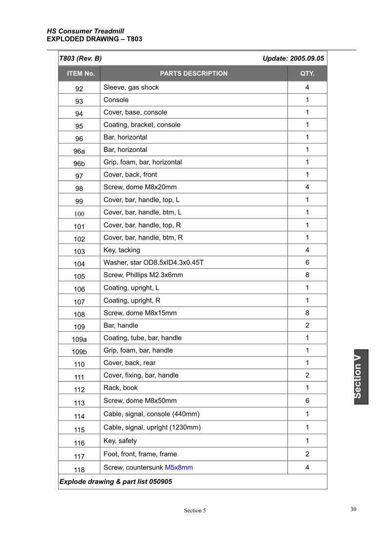
HS Consumer Treadmill EXPLODED DRAWING – T803
Section 5 30
Section V
T803 (Rev. B) Update: 2005.09.05
ITEM No. PARTS DESCRIPTION QTY.
92 Sleeve, gas shock 4
93 Console 1
94 Cover, base, console 1
95 Coating, bracket, console 1
96 Bar, horizontal 1
96a Bar, horizontal 1
96b Grip, foam, bar, horizontal 1
97 Cover, back, front 1
98 Screw, dome M8x20mm 4
99 Cover, bar, handle, top, L 1
100 Cover, bar, handle, btm, L 1
101 Cover, bar, handle, top, R 1
102 Cover, bar, handle, btm, R 1
103 Key, tacking 4
104 Washer, star OD8.5xID4.3x0.45T 6
105 Screw, Phillips M2.3x6mm 8
106 Coating, upright, L 1
107 Coating, upright, R 1
108 Screw, dome M8x15mm 8
109 Bar, handle 2
109a Coating, tube, bar, handle 1
109b Grip, foam, bar, handle 1
110 Cover, back, rear 1
111 Cover, fixing, bar, handle 2
112 Rack, book 1
113 Screw, dome M8x50mm 6
114 Cable, signal, console (440mm) 1
115 Cable, signal, upright (1230mm) 1
116 Key, safety 1
117 Foot, front, frame, frame 2
118 Screw, countersunk M5x8mm 4
Explode drawing & part list 050905
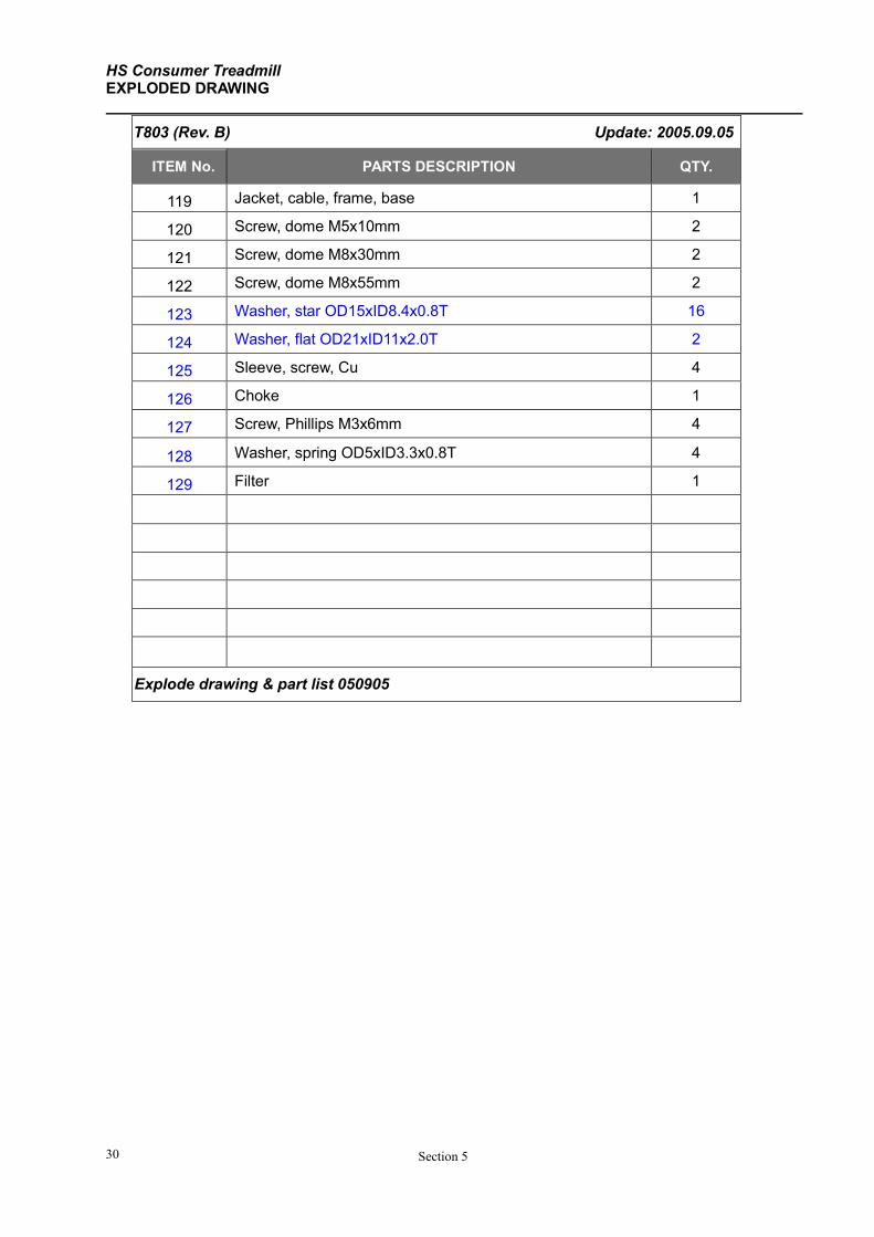
HS Consumer Treadmill EXPLODED DRAWING
Section 5 30
T803 (Rev. B) Update: 2005.09.05
ITEM No. PARTS DESCRIPTION QTY.
119 Jacket, cable, frame, base 1
120 Screw, dome M5x10mm 2
121 Screw, dome M8x30mm 2
122 Screw, dome M8x55mm 2
123 Washer, star OD15xID8.4x0.8T 16
124 Washer, flat OD21xID11x2.0T 2
125 Sleeve, screw, Cu 4
126 Choke 1
127 Screw, Phillips M3x6mm 4
128 Washer, spring OD5xID3.3x0.8T 4
129 Filter 1
Explode drawing & part list 050905

HS Consumer Treadmill EXPLODED DRAWING – T803
Section 5 32
Section VI
SECTION VI
MISCELLANEOUS INFORMATION

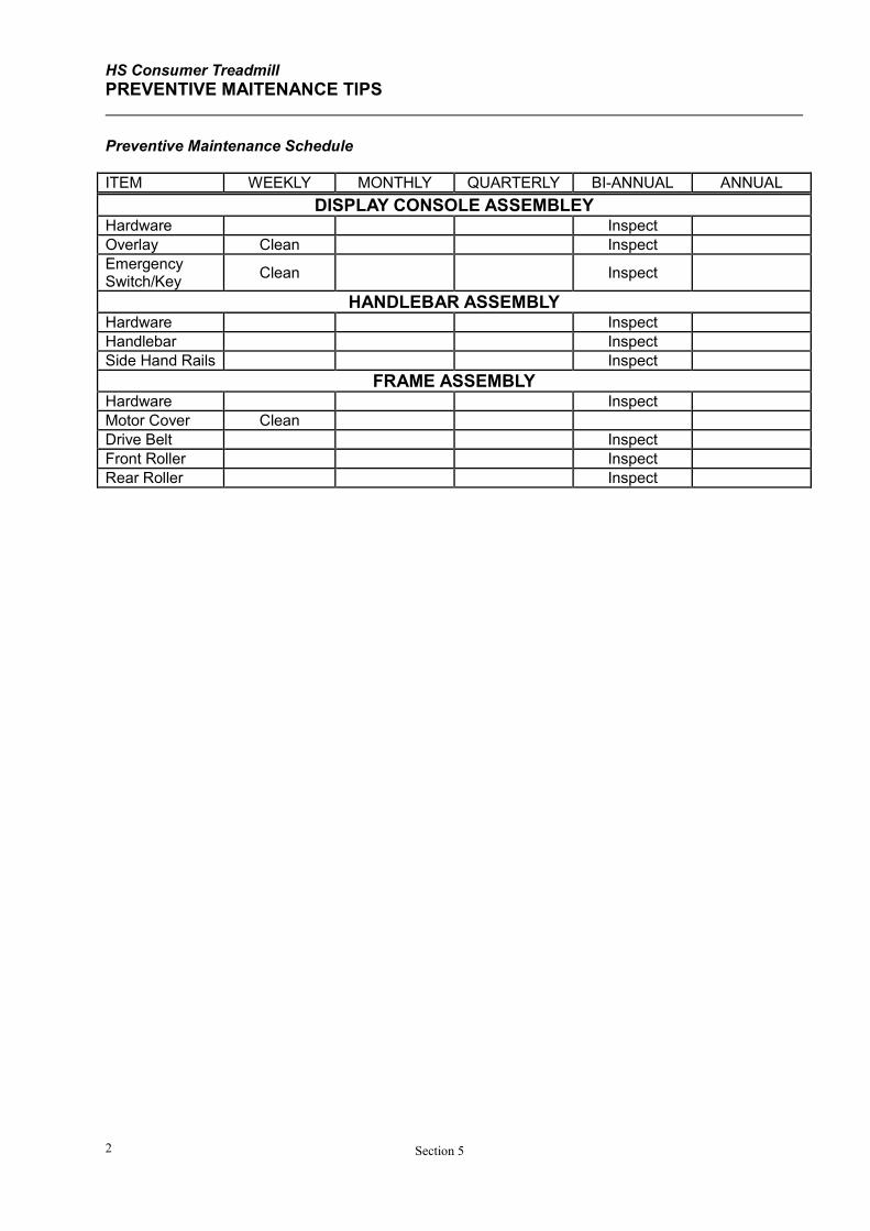
HS Consumer Treadmill
PREVENTIVE MAITENANCE TIPS
Section 5 2
Preventive Maintenance Schedule
ITEM WEEKLY MONTHLY QUARTERLY BI-ANNUAL ANNUAL
DISPLAY CONSOLE ASSEMBLEY Hardware Inspect
Overlay Clean Inspect
Emergency Switch/Key
Clean Inspect
HANDLEBAR ASSEMBLY Hardware Inspect
Handlebar Inspect
Side Hand Rails Inspect
FRAME ASSEMBLY Hardware Inspect
Motor Cover Clean
Drive Belt Inspect
Front Roller Inspect
Rear Roller Inspect
HS Consumer Treadmill UNPACKGING INSTRUCTIONS
Section 6 3
Section VI
CAUTION: For your own safety, be sure to fold up the deck before removing the treadmill from the carton. 1. Remove the computer console box and uprights set carefully. 2. Remove all the packaging materials. 3. Find and read the assembly instructions before assembling the treadmill. 4. Assemble the treadmill according to assembly instructions. 5. Fold up and move out the treadmill from carton packaging.
HS Consumer Treadmill INSALLATION INSTRUCTIONS
Section 5 4
IMPORTANT SAFETY INSTRUCTIONS !
⇒ DO NOT position the rear of the treadmill within 6 feet (2 meter) of the nearest obstruction. The sides of the treadmill should maintain a minimum clearance of 8 inches (20 cm) from the nearest treadmill or other obstruction.
⇒ DO NOT locate the treadmill outdoors, near swimming pools, or in areas of high humidity.
⇒ DO verify the contents of the delivery carton against the accompanying parts listing prior to setting the cartons and shipping material aside. If any part is missing, contact Customer Support Services at the number listed on the back page of this assembly instruction booklet. Save the shipping cartons in case of return.
⇒ DO read the entire Operation Manual prior to attempting to operate this machine, as this is essential for proper use. The Manual explains how to properly use the treadmill and helps you design an aerobic workout tailored to your personal fitness needs or requirements.
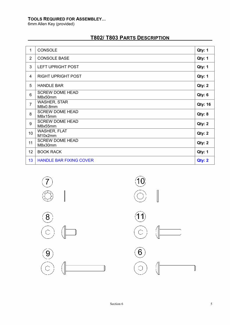
TOOLS REQUIRED FOR ASSEMBLEY… 6mm Allen Key (provided)
Section 6 5
T802/ T803 PARTS DESCRIPTION
1 CONSOLE Qty: 1
2 CONSOLE BASE Qty: 1
3 LEFT UPRIGHT POST Qty: 1
4 RIGHT UPRIGHT POST Qty: 1
5 HANDLE BAR Qty: 2
6 SCREW DOME HEAD M8x50mm
Qty: 6
7 WASHER, STAR M8x0.8mm
Qty: 16
8 SCREW DOME HEAD M8x15mm
Qty: 8
9 SCREW DOME HEAD M8x55mm
Qty: 2
10 WASHER, FLAT M10x2mm
Qty: 2
11 SCREW DOME HEAD M8x30mm
Qty: 2
12 BOOK RACK Qty: 1
13 HANDLE BAR FIXING COVER Qty: 2
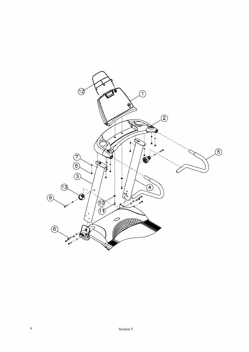
Section 5 6
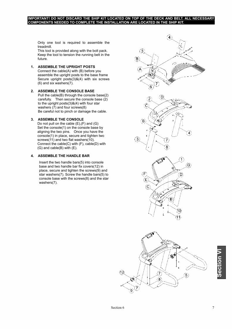
IMPORTANT! DO NOT DISCARD THE SHIP KIT LOCATED ON TOP OF THE DECK AND BELT. ALL NECESSARY COMPONENTS NEEDED TO COMPLETE THE INSTALLATION ARE LOCATED IN THE SHIP KIT.
Section 6 7
Section VI
Only one tool is required to assemble the treadmill. This tool is provided along with the bolt pack. Keep the tool to tension the running belt in the future.
1. ASSEMBLE THE UPRIGHT POSTS
Connect the cable(A) with (B) before you assemble the upright posts to the base frame Secure upright posts(3)&(4) with six screws (6) and six washers(7).
2. ASSEMBLE THE CONSOLE BASE
Pull the cable(B) through the console base(2) carefully. Then secure the console base (2) to the upright posts(3)&(4) with four star washers (7) and four screws(8)
Be careful not to pinch or damage the cable. 3. ASSEMBLE THE CONSOLE
Do not pull on the cable (E),(F) and (G) Set the console(1) on the console base by aligning the two pins. Once you have the console(1) in place, secure and tighten two screws(11) and two flat washers(10). Connect the cable(C) with (F), cable(D) with (G) and cable(B) with (E).
4. ASSEMBLE THE HANDLE BAR
Insert the two handle bars(5) into console base and two handle bar fix covers(12) in place, secure and tighten the screws(9) and star washers(7). Screw the handle bars(5) to console base with the screws(8) and the star washers(7).
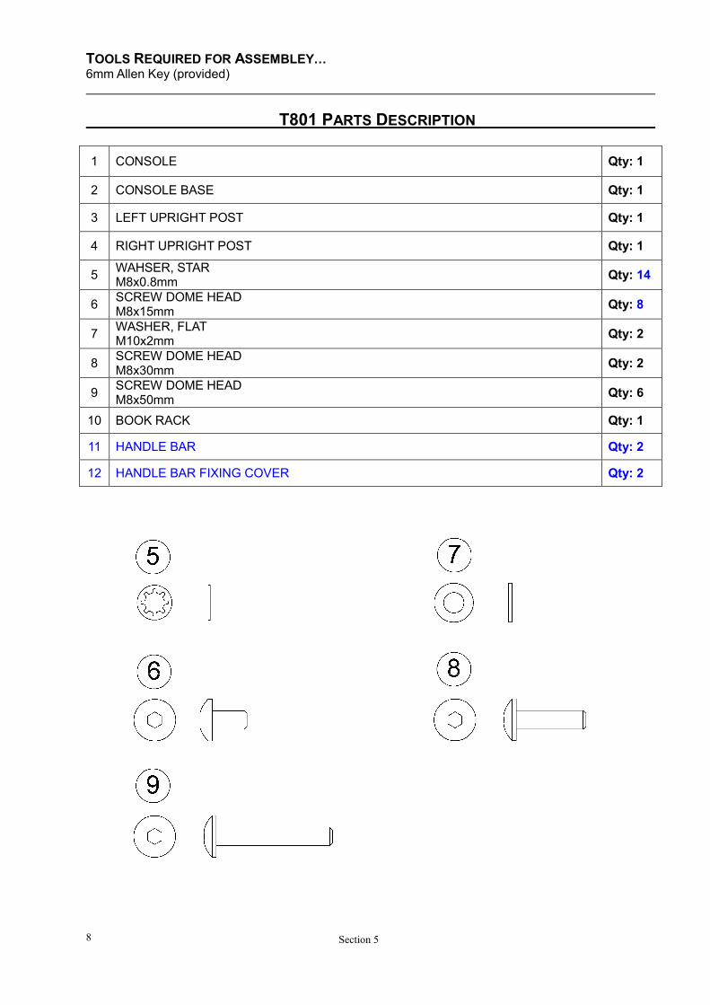
TOOLS REQUIRED FOR ASSEMBLEY… 6mm Allen Key (provided)
Section 5 8
T801 PARTS DESCRIPTION
1 CONSOLE Qty: 1
2 CONSOLE BASE Qty: 1
3 LEFT UPRIGHT POST Qty: 1
4 RIGHT UPRIGHT POST Qty: 1
5 WAHSER, STAR M8x0.8mm
Qty: 14
6 SCREW DOME HEAD M8x15mm
Qty: 8
7 WASHER, FLAT M10x2mm
Qty: 2
8 SCREW DOME HEAD M8x30mm
Qty: 2
9 SCREW DOME HEAD M8x50mm
Qty: 6
10 BOOK RACK Qty: 1
11 HANDLE BAR Qty: 2
12 HANDLE BAR FIXING COVER Qty: 2
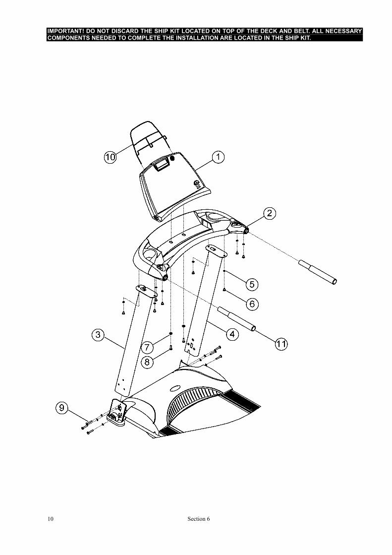
IMPORTANT! DO NOT DISCARD THE SHIP KIT LOCATED ON TOP OF THE DECK AND BELT. ALL NECESSARY COMPONENTS NEEDED TO COMPLETE THE INSTALLATION ARE LOCATED IN THE SHIP KIT.
Section 6 10
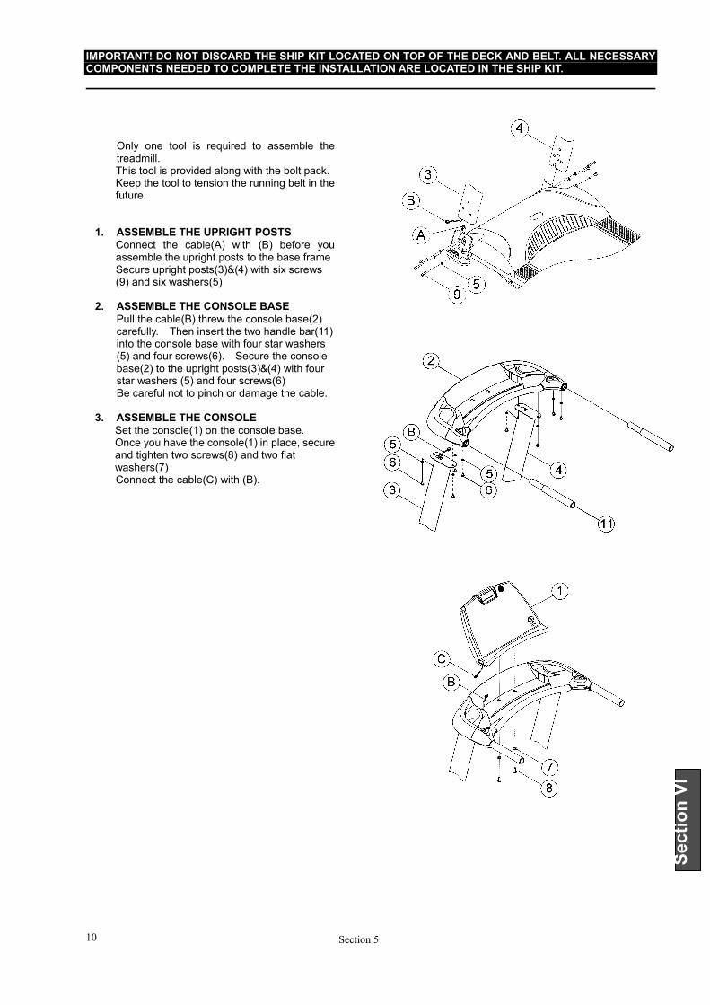
IMPORTANT! DO NOT DISCARD THE SHIP KIT LOCATED ON TOP OF THE DECK AND BELT. ALL NECESSARY COMPONENTS NEEDED TO COMPLETE THE INSTALLATION ARE LOCATED IN THE SHIP KIT.
Section 5 10
Section VI
Only one tool is required to assemble the treadmill. This tool is provided along with the bolt pack. Keep the tool to tension the running belt in the future.
1. ASSEMBLE THE UPRIGHT POSTS
Connect the cable(A) with (B) before you assemble the upright posts to the base frame Secure upright posts(3)&(4) with six screws (9) and six washers(5)
2. ASSEMBLE THE CONSOLE BASE
Pull the cable(B) threw the console base(2) carefully. Then insert the two handle bar(11) into the console base with four star washers (5) and four screws(6). Secure the console base(2) to the upright posts(3)&(4) with four star washers (5) and four screws(6)
Be careful not to pinch or damage the cable. 3. ASSEMBLE THE CONSOLE
Set the console(1) on the console base. Once you have the console(1) in place, secure and tighten two screws(8) and two flat washers(7) Connect the cable(C) with (B).

HS Consumer Treadmill
COMMUNICATING BY FAX
Section 6 11
Section VI
If you would like to submit a part order, or if you need help troubleshooting a problem, we have included, for your convenience, a FAX form on the following page. Simply make a copy (or copies) of the FAX sheet and fill in the necessary information. You may FAX us at any time, 24 hours a day, to either of the numbers shown. A HS service representative will process your order, or respond to your problem, as quickly as possible.
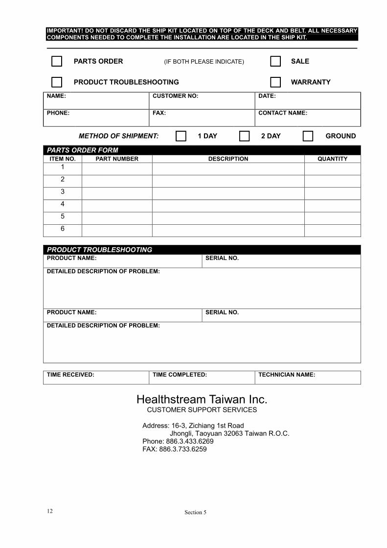
IMPORTANT! DO NOT DISCARD THE SHIP KIT LOCATED ON TOP OF THE DECK AND BELT. ALL NECESSARY COMPONENTS NEEDED TO COMPLETE THE INSTALLATION ARE LOCATED IN THE SHIP KIT.
Section 5 12
□□□□ PARTS ORDER (IF BOTH PLEASE INDICATE) □□□□ SALE
□□□□ PRODUCT TROUBLESHOOTING □□□□ WARRANTY
NAME: CUSTOMER NO: DATE:
PHONE: FAX: CONTACT NAME:
METHOD OF SHIPMENT: □□□□ 1 DAY □□□□ 2 DAY □□□□ GROUND
PARTS ORDER FORM
ITEM NO. PART NUMBER DESCRIPTION QUANTITY
1
2
3
4
5
6
PRODUCT TROUBLESHOOTING PRODUCT NAME: SERIAL NO.
DETAILED DESCRIPTION OF PROBLEM:
PRODUCT NAME: SERIAL NO.
DETAILED DESCRIPTION OF PROBLEM:
TIME RECEIVED: TIME COMPLETED: TECHNICIAN NAME:
Healthstream Taiwan Inc. CUSTOMER SUPPORT SERVICES
Address: 16-3, Zichiang 1st Road
Jhongli, Taoyuan 32063 Taiwan R.O.C. Phone: 886.3.433.6269 FAX: 886.3.733.6259

HS Consumer Treadmill
NOTES:
Section 6 13
Section VI


