
TRACE 1300 and TRACE 1310 Gas Chromatographs
Deans Switch MicrofluidicsInstallation Guide
31709740 Revision A June 2014

© 2014 Thermo Fisher Scientific Inc. All rights reserved. TRACE 1300, and TRACE 1310 are trademarks of Thermo Fisher Scientific. SilFlow, and FingerTite are registered trademarks of SGE Analytical Science. All other trademarks are the property of Thermo Fisher Scientific and its subsidiaries.
Thermo Fisher Scientific Inc. provides this document to its customers with a product purchase to use in the product operation. This document is copyright protected and any reproduction of the whole or any part of this document is strictly prohibited, except with the written authorization of Thermo Fisher Scientific Inc.
The contents of this document are subject to change without notice. All technical information in this document is for reference purposes only. System configurations and specifications in this document supersede all previous information received by the purchaser.
This document is not part of any sales contract between Thermo Fisher Scientific Inc. and a purchaser. This document shall in no way govern or modify any Terms and Conditions of Sale, which Terms and Conditions of Sale shall govern all conflicting information between the two documents.
Release history: Revision A, May 2014
For Research Use Only. Not for use in diagnostic procedures.

Thermo Scientific Deans Switch Microfluidics Installation Guide iii
C
Chapter 1 Deans Switch Microfluidics Installation Guide . . . . . . . . . . . . . . . . . . . . . . . . . . . .1Introduction . . . . . . . . . . . . . . . . . . . . . . . . . . . . . . . . . . . . . . . . . . . . . . . . . . . . 2Installing the Deans Switch Microfluidics Kit . . . . . . . . . . . . . . . . . . . . . . . . . . . 2
Installing the Auxiliary Gas Module . . . . . . . . . . . . . . . . . . . . . . . . . . . . . . . . 2Installing and Connecting the Auxiliary Gas Module . . . . . . . . . . . . . . . . . . . 6Installing the Mounting Bracket . . . . . . . . . . . . . . . . . . . . . . . . . . . . . . . . . . 11Preparing and Connecting the Tubings to the SilFlow™ Deans Switch . . . . . 13Connecting the Auxiliary Gas Module. . . . . . . . . . . . . . . . . . . . . . . . . . . . . . 16Restarting the GC . . . . . . . . . . . . . . . . . . . . . . . . . . . . . . . . . . . . . . . . . . . . . 17
Installing the Deans Switch Calculator Program . . . . . . . . . . . . . . . . . . . . . . . . 18Deans Switch Calculator Description . . . . . . . . . . . . . . . . . . . . . . . . . . . . . . . . 23
Main User Interface. . . . . . . . . . . . . . . . . . . . . . . . . . . . . . . . . . . . . . . . . . . . 23Menu Bar . . . . . . . . . . . . . . . . . . . . . . . . . . . . . . . . . . . . . . . . . . . . . . . . . . . 24Options Bar. . . . . . . . . . . . . . . . . . . . . . . . . . . . . . . . . . . . . . . . . . . . . . . . . . 27Parameters Dialog Window. . . . . . . . . . . . . . . . . . . . . . . . . . . . . . . . . . . . . . 28Comments Bar . . . . . . . . . . . . . . . . . . . . . . . . . . . . . . . . . . . . . . . . . . . . . . . 35
Running the Deans Switch Wizard . . . . . . . . . . . . . . . . . . . . . . . . . . . . . . . . . . 35
Contents


Thermo Scientific Deans Switch Microfluidics Installation Guide 1
Deans Switch Microfluidics Installation Guide
This guide provides instructions for installing the Deans Switch Microfluidics on your TRACE 1300 or TRACE 1310 GC.
Contents
• Introduction
• Installing the Deans Switch Microfluidics Kit
• Installing the Deans Switch Calculator Program
• Deans Switch Calculator Description
• Running the Deans Switch Wizard

Deans Switch Microfluidics Installation GuideIntroduction
2 Deans Switch Microfluidics Installation Guide Thermo Scientific
IntroductionThe Deans Switch Microfluidics, provided with the kit PN 19005580, is used for applying analytical cuts on the chromatogram.
• See “Installing the Deans Switch Microfluidics Kit” on page 2
• See “Installing the Deans Switch Calculator Program” on page 18 and “Deans Switch Calculator Description” on page 23
Installing the Deans Switch Microfluidics KitFor installing the Deans Switch Microfluidics kit see the following sections:
• “Installing the Auxiliary Gas Module” on page 2
• “Installing and Connecting the Auxiliary Gas Module” on page 6
• “Installing the Mounting Bracket” on page 11
• “Preparing and Connecting the Tubings to the SilFlow™ Deans Switch” on page 13
• “Connecting the Auxiliary Gas Module” on page 16
• “Restarting the GC” on page 17
Installing the Auxiliary Gas Module
This section provides instructions for installing the Auxiliary Gas module into the TRACE 1300/TRACE 1310.
To install the auxiliary gas interface on the right wall of the oven
1. Put the GC in standby condition.
2. Cool the oven, injectors, and detectors to room temperature.
3. Close the gas supplies.
4. Power off the GC.
WARNING This operation must be carried out by authorized and trained Thermo Fisher Scientific Service Field Engineers.
The Auxiliary Gas Module is shipped with a protecting plate screwed on the manifold. Remove this plate before installing the module. See the section Installing and Connecting the Auxiliary Gas Module on page 6 for details.
Note By pressing the Maintenance button, the GC cool down is automatically carried out.
Deans Switch Microfluidics Installation GuideInstalling the Deans Switch Microfluidics Kit
Thermo Scientific Deans Switch Microfluidics Installation Guide 3
a. Push down the power switch (breaker), located at the back of the instrument, to the position O.
b. Unplug the power cable from the AC Input connector on the back of the GC, and from the wall outlet.
5. If external modules are present, unplug the power cable from the AC Input connector of each external module, and from the wall outlet.
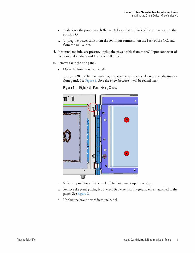
6. Remove the right side panel.
a. Open the front door of the GC.
b. Using a T20 Torxhead screwdriver, unscrew the left side panel screw from the interior front panel. See Figure 1. Save the screw because it will be reused later.
Figure 1. Right Side Panel Fixing Screw
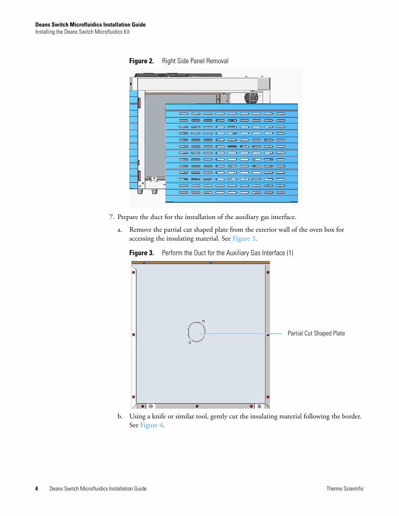
c. Slide the panel towards the back of the instrument up to the stop.
d. Remove the panel pulling it outward. Be aware that the ground wire is attached to the panel. See Figure 2.
e. Unplug the ground wire from the panel.
Deans Switch Microfluidics Installation GuideInstalling the Deans Switch Microfluidics Kit
4 Deans Switch Microfluidics Installation Guide Thermo Scientific
Figure 2. Right Side Panel Removal
7. Prepare the duct for the installation of the auxiliary gas interface.
a. Remove the partial cut shaped plate from the exterior wall of the oven box for accessing the insulating material. See Figure 3.
Figure 3. Perform the Duct for the Auxiliary Gas Interface (1)
b. Using a knife or similar tool, gently cut the insulating material following the border. See Figure 4.
Partial Cut Shaped Plate

Deans Switch Microfluidics Installation GuideInstalling the Deans Switch Microfluidics Kit
Thermo Scientific Deans Switch Microfluidics Installation Guide 5
Figure 4. Perform the Duct for the Auxiliary Gas Interface (2)
c. Save the removed insulating material in a safe place because it can be reused.
d. On the left side wall in the interior of the oven, remove the partial cut plate from the corresponding duct. See Figure 5.
Figure 5. Perform the Duct for the Auxiliary Gas Interface (3)
e. Insert the auxiliary gas interface into the duct.
f. Fix the interface on the exterior wall of the oven box using the fixing screws provided. See Figure 6.
Partial Cut Plate

Deans Switch Microfluidics Installation GuideInstalling the Deans Switch Microfluidics Kit
6 Deans Switch Microfluidics Installation Guide Thermo Scientific
Figure 6. Perform the Duct for the Auxiliary Gas Interface (4)
8. Go to the section “Installing and Connecting the Auxiliary Gas Module” on page 6.
Installing and Connecting the Auxiliary Gas Module
To install and connect the Auxiliary Gas Module
1. Remove the cover of the external modules housing where installing the module. See Figure 7.
External View
Internal View

Deans Switch Microfluidics Installation GuideInstalling the Deans Switch Microfluidics Kit
Thermo Scientific Deans Switch Microfluidics Installation Guide 7
Figure 7. Housing Cover Removal
a. Using a T20 Torxhead screwdriver, unscrew and remove the left housing cover screws.
b. Remove the cover from the housing.
2. Remove the manifold protecting plate
a. Using a T20 Torxhead screwdriver, unscrew the two fixing screws, and remove the protecting plate from the manifold. Save the protecting plate and the fixing screws.
Figure 8. Manifold Protecting Plate
3. Install the module into the housing
a. Loosen the two hexagonal screws under the module. See Figure 9.
Left/Right Housing Covers
Left CoverScrews
Right CoverScrews
Protecting Plate
Fixing Screws

Deans Switch Microfluidics Installation GuideInstalling the Deans Switch Microfluidics Kit
8 Deans Switch Microfluidics Installation Guide Thermo Scientific
Figure 9. Module Installation (1)
b. Carefully place the module into the left or right housing.
c. Push the module until the hexagonal screws couple with the slots on the floor of the GC. See Figure 10.
Figure 10. Module Installation (2)
d. Finger-tighten the hexagonal screws slightly, or use a 10-mm wrench.
Note Always keep the hexagonal screws in their place. This allows you an easier removal of the auxiliary module when necessary.
Hexagonal Screws
Slots

Deans Switch Microfluidics Installation GuideInstalling the Deans Switch Microfluidics Kit
Thermo Scientific Deans Switch Microfluidics Installation Guide 9
The result of the installation is shown in Figure 11.
Figure 11. Auxiliary Gas Module Installed into the GC
4. Connect the gas tubing block to the manifold.
Figure 12 shows the gas tubing block and the manifold located into the auxiliary gas module.
Figure 12. Gas Tubing Block and Manifold
a. Carefully guide the gas tubing block on the manifold located into the auxiliary gas module. See Figure 13.
Auxiliary Gas Module
Cables Holder
Gas Tubing Block
Manifold
Fixing Screws
Fixing Holes

Deans Switch Microfluidics Installation GuideInstalling the Deans Switch Microfluidics Kit
10 Deans Switch Microfluidics Installation Guide Thermo Scientific
Figure 13. Installation on the Left Side
b. Align the fixing screws of the gas tubing block with the corresponding holes on the manifold.
c. Use the T20 Torxhead screwdriver to tighten the two fixing screws without overtightening.
5. Connect the gas tubes to the Auxiliary Gas Interface.
a. Guide the three gas tubes up to reach the Auxiliary Gas interface.
b. Bend the gas tube until its end reaches the corresponding numbered inlet port of the auxiliary interface.
c. Connect the gas tube to the corresponding numbered inlet port using the appropriate nut and ferrules. Use a 7/16-in. wrench to tighten the fittings.
Note The length of the tubes allows them to reach the Auxiliary Gas Interface whether they are installed on the same side or on the opposite side of the Auxiliary Gas Module.
ATTENTION The three gas tubes, coming from the gas tubing block, are numbered 1, 2, and 3 respectively. Pay attention to the correct order when you connect each tube to the corresponding inlet on the auxiliary gas interface. The end of each tube is provided with a label indicating the type of gas.

Deans Switch Microfluidics Installation GuideInstalling the Deans Switch Microfluidics Kit
Thermo Scientific Deans Switch Microfluidics Installation Guide 11
d. Repeat step b and step c until all the gas tubes are connected to the auxiliary gas interface. See Figure 14.
Figure 14. Gas Tubes Connection to the Auxiliary Gas Interface - External View(
Installing the Mounting Bracket
Install the mounting bracket near the front of the GC oven on the right-hand side. This will keep the mounting bracket out of the way of the column.
To install the mounting bracket
1. Remove the nut at the top end of the mounting bracket. This nut secures the two sections of the mounting bracket. See Figure 15.
Figure 15. Mounting Bracket Parts
2. Push the top of the mounting bracket down.
3. Line up the bottom of the mounting bracket into two holes on the bottom side of the GC oven.
4. Hold the mounting bracket directly upright, and twist the top end of it so that it is securely attached to the GC oven holes.
Note If you already have a mounting bracket installed in your GC with either the SSL or PTV backflush kit, skip this step.
BottomNutHolder
Top

Deans Switch Microfluidics Installation GuideInstalling the Deans Switch Microfluidics Kit
12 Deans Switch Microfluidics Installation Guide Thermo Scientific
5. Let out the top of the mounting bracket until it is long enough to be secured into two holes on the bottom of the GC oven.
6. Loosely replace the nut, then rotate the top and bottom in opposite directions.
7. Tighten the nut until the mounting bracket is securely attached to the top and bottom of the GC oven.
Figure 16. Mounting Bracket Installed in the GC
8. Attach the Thermo Scientific™ microfluidics deans switch to the mounting bracket. The microfluidics deans switch snaps into place. The small hole should be positioned at the top. See Figure 17 for the correct orientation.
Figure 17. Correct Orientation for the Microfluidics Deans SwitchSmall Hole
Front
Back

Deans Switch Microfluidics Installation GuideInstalling the Deans Switch Microfluidics Kit
Thermo Scientific Deans Switch Microfluidics Installation Guide 13
9. Position the holder for the microfluidics deans switch upright and use two 7 mm wrenches to secure it.
Preparing and Connecting the Tubings to the SilFlow™ Deans Switch
You need the following material to connect the tubings to new ferrule and nut. They are all included in the complete kit.
• A 5-ports SilFlow™ microfluidics deans switch• SilFlow™ pre-swage tool and SilFlow FingerTite tool—to pre-swage the SilFlow ferrule to
the microfluidics deans switch• SilFlow nut—to connect the tubing to the microfluidics deans switch• SilFlow ferrules (3)
• Two metal tubing restrictors for the connection with the auxiliary gas interface• Two meters long, 0.1 mm i.d. fused silica restrictors
To prepare the tubings
1. Position a SilFlow nut and SilFlow ferrule onto the tubing as shown in Figure 18.
Figure 18. Positioning the SilFlow Nut and SilFlow Ferrule Correctly on the Tubing
2. Use a scoring wafer to cut the tubing after inserting it through the ferrule. See Figure 19. Then use the SilFlow pre-swage tool to secure the ferrule into position.
When done properly, the tubing will extend slightly past the tip of the ferrule. It is important to use the SilFlow pre-swage tool in order to prevent crushing the tip of the fused silica.
Figure 19. Cutting the Tubing with the Scoring Wafer
Note If you are using a 0.25 mm id column, use a 0.4 mm SilFlow ferrule and a 0.4 mm SilFlow FingerTite jig. If you are using a 0.32 mm id column, use a 0.5 mm SilFlow ferrule and a 0.5 mm SilFlow FingerTite jig.

Deans Switch Microfluidics Installation GuideInstalling the Deans Switch Microfluidics Kit
14 Deans Switch Microfluidics Installation Guide Thermo Scientific
3. Place the column and ferrule into SilFlow pre-swage tool until the tubing reaches the bottom of the tool. When done properly, the tubing will extend slightly past the tip of the ferrule. It is important to use the pre-swage tool in order to prevent crushing the tip of the fused silica. See Figure 20.
Figure 20. Inserting the Column and Ferrule into the SilFlow Pre-Swage Tool
4. Use the SilFlow FingerTite tool to swage the ferrule to the tubing. Be sure to keep the tip of the fused silica bottomed out in the pre-swage tool. See Figure 21.
Figure 21. Swaging the Ferrule Using the SilFlow FingerTite Tool
5. Remove the jig, and lay the tubing carefully on the bottom of the GC until you are ready to connect it to the microfluidics deans switch.
To connect the tubings to the auxiliary gas interface and to the 5-port SilFlow™ Deans Switch
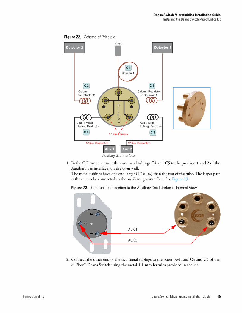
Perform the pneumatic connection according to the scheme of principle visualized in Figure 22.
SilFlow Pre-Swage Tool
SilFlow FingerTite Pre-Swage Tool
Deans Switch Microfluidics Installation GuideInstalling the Deans Switch Microfluidics Kit
Thermo Scientific Deans Switch Microfluidics Installation Guide 15
Figure 22. Scheme of Principle
1. In the GC oven, connect the two metal tubings C4 and C5 to the position 1 and 2 of the Auxiliary gas interface, on the oven wall. The metal tubings have one end larger (1/16-in.) than the rest of the tube. The larger part is the one to be connected to the auxiliary gas interface. See Figure 23.
Figure 23. Gas Tubes Connection to the Auxiliary Gas Interface - Internal View
2. Connect the other end of the two metal tubings to the outer positions C4 and C5 of the SilFlow™ Deans Switch using the metal 1.1 mm ferrules provided in the kit.
Detector 1Detector 2Inlet
Aux 1 Aux 2
1.1 mm Ferrules
1/16-in. Connection 1/16-in. Connection
Aux 1 Metal Tubing Restrictor
Aux 2 Metal Tubing Restrictor
Column Restrictor to Detector 1
SILFOW
Column 1
Column to Detector 2
C 1
C 2 C 3
C 4 C 5
Auxiliary Gas Interface
AUX 1
AUX 2
C5C4
Deans Switch Microfluidics Installation GuideInstalling the Deans Switch Microfluidics Kit
16 Deans Switch Microfluidics Installation Guide Thermo Scientific
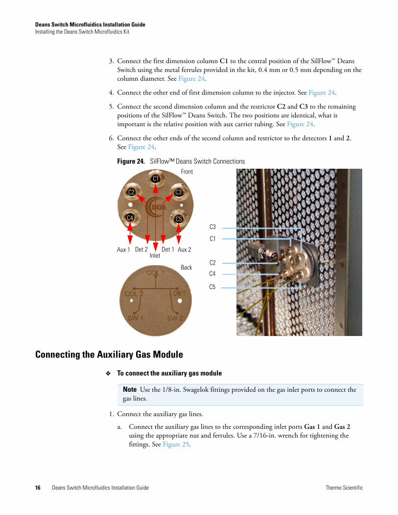
3. Connect the first dimension column C1 to the central position of the SilFlow™ Deans Switch using the metal ferrules provided in the kit, 0.4 mm or 0.5 mm depending on the column diameter. See Figure 24.
4. Connect the other end of first dimension column to the injector. See Figure 24.
5. Connect the second dimension column and the restrictor C2 and C3 to the remaining positions of the SilFlow™ Deans Switch. The two positions are identical, what is important is the relative position with aux carrier tubing. See Figure 24.
6. Connect the other ends of the second column and restrictor to the detectors 1 and 2. See Figure 24.
Figure 24. SilFlow™ Deans Switch Connections
Connecting the Auxiliary Gas Module
To connect the auxiliary gas module
1. Connect the auxiliary gas lines.
a. Connect the auxiliary gas lines to the corresponding inlet ports Gas 1 and Gas 2 using the appropriate nut and ferrules. Use a 7/16-in. wrench for tightening the fittings. See Figure 25.
C1
C2
C3
C4
C5
C3
C5
Front
Back
C1
C2
C4
InletDet 1Det 2Aux 1 Aux 2
Note Use the 1/8-in. Swagelok fittings provided on the gas inlet ports to connect the gas lines.

Deans Switch Microfluidics Installation GuideInstalling the Deans Switch Microfluidics Kit
Thermo Scientific Deans Switch Microfluidics Installation Guide 17
Figure 25. Gas Line Connection to the Auxiliary Gas Interface
2. Connect the auxiliary gas module electrically.
a. Using the cable provided, connect the 15-pin female connector marked GC Bus on the module to a Bus interface on the back of the GC. See Figure 26.
Figure 26. Electrical Connection
Restarting the GC
To restart the GC
1. Replace the left/right side panel.
a. Plug the ground wire previously removed into the left/right panel.
b. Place the left/right panel and attach the screw holding it in place.
IMPORTANT The maximum nominal inlet pressure for all the inputs is 1000 kPa (145 psig). The working inlet pressure range is from 400 kPa (58 psig) to 1000 kPa (145 psig).

Deans Switch Microfluidics Installation GuideInstalling the Deans Switch Calculator Program
18 Deans Switch Microfluidics Installation Guide Thermo Scientific
2. Open the gas supplies.
3. If external modules are present, plug the power cable to the AC Input connector of each external module, and to the wall outlet.
4. Power on the GC.
a. Plug the power cable to the AC Input connector into the back of the GC and to the wall outlet.
b. Flip up the power switch (breaker), located at the back of the instrument, to the position I.
5. Configure and enable the Auxiliary Gas system through the user interface of your GC, or through the CDS in use. Refer to the TRACE 1300 and TRACE 1310 User Guide.
a. Configuration and enabling through the touch screen.
i. In the main menu select the Instrument control icon. The Instrument Control menu appears.
ii. In the Instrument Control menu, select the Auxiliary icon to open the relevant submenu.
iii. Set the Aux Gas Pressure values as required, then return to main menu.
b. Configuration and enabling through the Chromatography Data System.
i. In the Configuration window select the Auxiliary tab.
ii. Select the check box Auxiliary Carrier Module 1/2 according to the auxiliary carrier module installed on your GC.
iii. Select the Auxiliary Pressure check box to enable up to six auxiliary Pressures, and the adjacent field.
iv. According the inlet ports connected to the Auxiliary Gas Interface, select the corresponding check box and set the pressure in the adjacent field.
6. Set the normal detector, injector, and GC working conditions.
Installing the Deans Switch Calculator ProgramThis section provides the instruction for installing and using the program Deans Switch Calculator on your computer.
To install the Deans Switch Calculator program on you computer
1. Turn on the computer and allow it to complete its boot process.
2. Insert the DVD provided into the drive and start Setup Launcher. The following window is displayed. See Figure 27.

Deans Switch Microfluidics Installation GuideInstalling the Deans Switch Calculator Program
Thermo Scientific Deans Switch Microfluidics Installation Guide 19
Figure 27. DSC Program Installation (1)
3. Wait for the preliminary phase of the installation. At the end of the operation the following page is displayed. See Figure 28.
Figure 28. DSC Program Installation (2)
4. Click Next to continue, the following window is displayed. See Figure 29.
Figure 29. DSC Program Installation (3)
5. To continue the installation procedure select I Accept the terms in license agreement, then click Next to continue; the following window is displayed. See Figure 30.

Deans Switch Microfluidics Installation GuideInstalling the Deans Switch Calculator Program
20 Deans Switch Microfluidics Installation Guide Thermo Scientific
Figure 30. DSC Program Installation (4)
6. Be sure that any previous Thermo Deans Switch Calculator versions have been removed. If not, remove the previous versions; if yes click Next to continue. The following page is displayed. See Figure 31.
Figure 31. DSC Program Installation (4)
7. Select the installation folder. To install the program in a different folder click Change and specify the desired folder. Click Next to continue, the following window is displayed. See Figure 32.
Figure 32. DSC Program Installation (5)

Deans Switch Microfluidics Installation GuideInstalling the Deans Switch Calculator Program
Thermo Scientific Deans Switch Microfluidics Installation Guide 21
8. Click Install for starting the installation of the program. The following window is displayed. See Figure 33.
Figure 33. DSC Program Installation (6)
9. Wait for the installation of the program. At the end, the following window is displayed.See Figure 34.
Figure 34. DSC Program Installation (7)
10. Click Finish to exit the installation.
11. Run the DSC program selecting Start > All Programs > Thermo Deans Switch Calculator > Deans Switch Calculator.
The Main User Interface of the program is displayed. See Figure 35 and “Main User Interface” on page 23.

Deans Switch Microfluidics Installation GuideInstalling the Deans Switch Calculator Program
22 Deans Switch Microfluidics Installation Guide Thermo Scientific
Figure 35. DSC Program Main User Interface

Deans Switch Microfluidics Installation GuideDeans Switch Calculator Description
Thermo Scientific Deans Switch Microfluidics Installation Guide 23
Deans Switch Calculator DescriptionThis section provides the description of the Deans Switch Calculator program.
Main User Interface
The Main User Interface of the Deans Switch Calculator contains the menus, the text boxes, and the synoptic dialog window for setting the analytical parameters. See Figure 36.
Figure 36. Deans Switch Calculator Main User Interface
The Main User Interface includes the following sections:
• Menu Bar — Comprises the pull-down menus. See “Menu Bar” on page 24.
• Options Bar — Comprises the Pressure type and Gas Type fields. See “Options Bar” on page 27.
• Dean Switch Pressures, Temperatures, and Flows — Comprises a dialog window including the synoptic of the pneumatic circuit and the buttons for creating your analytical method. See “Parameters Dialog Window” on page 28.
• Archive C:\Thermo\Thermo Deans Switch Calculator\data\default.ds — Comprises an un-editable text box where comments could be visualized during the analysis. See “Comments Bar” on page 35.
Menu Bar
Options Bar
Parameters Dialog Window and Synoptic
Comment Text Box

Deans Switch Microfluidics Installation GuideDeans Switch Calculator Description
24 Deans Switch Microfluidics Installation Guide Thermo Scientific
Menu Bar
The menu bar comprises the File and Help pull-down menus. See Figure 37.
Figure 37. Menu Bar
File
This pull-down menu includes the following functions. See Figure 38.
Figure 38. Functions of the File Pull-down Menu
The functions of the File pull-down menu are detailed below:
Language — Selects the language among those available. Once any of the available language is selected, the menus, windows, functions, and messages will be in the selected one.
New — Creates a new method starting from the default parameters.
• At the first message visualized click OK to confirm.
• At the second message visualized click OK to exit.

Deans Switch Microfluidics Installation GuideDeans Switch Calculator Description
Thermo Scientific Deans Switch Microfluidics Installation Guide 25
Page Setup — Opens a page composed of four tabs for setting up the report page of your analytical method. The four tabs are the follows:.
Print Preview — Visualizes a preview of the report page according to the options set in Page Setup. The image below shows an example of report page.
• Page — Selects the options for setting the orientation, scaling, paper size, and page numbering of the report page.
• Margins — Selects the options for adjusting the margins of the report page.
• Header/Footer — Enters the text to visualize on the header and footer of the report page
• Sheet — Defines the print area, print titles, print options, and page order of the report page.

Deans Switch Microfluidics Installation GuideDeans Switch Calculator Description
26 Deans Switch Microfluidics Installation Guide Thermo Scientific
Print Black and White — Prints the report page in black and white.
Print — Prints the report page of the method on the current printer.
Open File — Loads the method from disk into computer memory.

Deans Switch Microfluidics Installation GuideDeans Switch Calculator Description
Thermo Scientific Deans Switch Microfluidics Installation Guide 27
Help
This menu includes the following function. See Figure 39.
Figure 39. Functions of the Help Pull-down Menu
Options Bar
The option bar comprises the following fields. See Figure 40.
Figure 40. Option Bar
Pressure Type — Choose the pressure unit psi, kPa, or bar by checking the corresponding radio button.
Gas Type — Choose the gas type He, H2, N2 or Ar by selecting the corresponding radio button.
Exit — Quits Deans Switch Calculator.
Click OK to exit the program.
About — Displays the version and the copyright of the program.
Click OK to exit.

Deans Switch Microfluidics Installation GuideDeans Switch Calculator Description
28 Deans Switch Microfluidics Installation Guide Thermo Scientific
Parameters Dialog Window
The parameter dialog window includes the synoptic of the pneumatic circuit and buttons for setting the parameters of your analytical method. The analytical parameters set and the direction of the flows are visualized accordingly. See Figure 41.
Figure 41. Parameters Dialog Window
For details see the following sections:
• “Wizard Button” on page 29
• “Flow Blue Arrows” on page 29
• “Inlet Parameters” on page 29
• “Detector 1 Parameters” on page 30
• “Detector 2 Parameters” on page 31
• “Aux 1 Parameters” on page 32
• “Aux 2 Parameters” on page 33
• “Oven Parameters” on page 34

Deans Switch Microfluidics Installation GuideDeans Switch Calculator Description
Thermo Scientific Deans Switch Microfluidics Installation Guide 29
Wizard Button
The Wizard button opens the Deans Switch Wizard dialog window for aid you in setting up the application.
Flow Blue Arrows
The blue arrows indicate the direction of the flows into the pneumatic circuit according the parameters set. The flows are numbered from F1 to F7 and their values are calculated automatically.
Inlet Parameters
Inlet Parameters define the inlet pressure P1 and the dimensions of the column C1. See Figure 42.
Figure 42. Inlet Parameters
Note For running properly the Deans Switch Wizard, see the section “Running the Deans Switch Wizard” on page 35.

Deans Switch Microfluidics Installation GuideDeans Switch Calculator Description
30 Deans Switch Microfluidics Installation Guide Thermo Scientific
Detector 1 Parameters
Detector 1 Parameters define the type of the first detector, the detector temperature, and the dimension of the column C3 connected to the detector 1. See Figure 43.
Figure 43. Detector 1 Parameters
P1 — Defines and visualizes the inlet pressure in the range from 0 to 1000 kPa, or 0 to 145 psi, or 0 to 10 bar.
C1 — Defines the length, internal diameter, and film thickness of the column 1 connected to the injector.
Detector Type — From the drop-down list choose one: FID, MS, ECD, TCD, FPD, and NPD.

Deans Switch Microfluidics Installation GuideDeans Switch Calculator Description
Thermo Scientific Deans Switch Microfluidics Installation Guide 31
Detector 2 Parameters
Detector 2 Parameters define the type of the second detector, the detector temperature, and the dimension of the column connected to the detector 2. See Figure 44.
Figure 44. Detector 1 Parameters
Detector Temperature — Defines and visualizes the temperature of the detector 1 in the range from 0 to 450 °C.
C3 — Defines the length, internal diameter, and film thickness of the column restrictor connected to the detector 1.
Selecting the Balance Col3 to Col2 check box the page change as shown in the adjacent image.
Clicking P-Mid the value of the pressure entered for the Balance Col3 to Col2 parameter is replaced by the value pressure present into the SilFlow™.

Deans Switch Microfluidics Installation GuideDeans Switch Calculator Description
32 Deans Switch Microfluidics Installation Guide Thermo Scientific
Aux 1 Parameters
Aux 1 Parameters define the pressure of the auxiliary gas line 1 and the dimension of the column connected. See Figure 45.
Figure 45. Aux 1 Parameters
Check box On — When selected enables the auxiliary gas 1.
Detector Type — From the drop-down list choose one: FID, MS, ECD, TCD, FPD, and NPD.
Detector Temperature — Defines the temperature of the detector 2 in the range from 0 to 450 °C.
C2 — Defines the length, internal diameter, and film thick of the column restrictor connected to the detector 2.

Deans Switch Microfluidics Installation GuideDeans Switch Calculator Description
Thermo Scientific Deans Switch Microfluidics Installation Guide 33
Aux 2 Parameters
Aux 2 Parameters define the pressure of the auxiliary gas line 2 and the dimension of the column connected. See Figure 46.
Figure 46. Aux 2 Parameters
Check box On — When selected enables the auxiliary gas 2.
P4 — Defines and visualizes the pressure of the auxiliary gas line 1 in the range from 0 to 1000 kPa, or 0 to 145 psi, or 0 to 10 bar.
C4 — Defines the length and internal diameter of the restrictor connected to the auxiliary gas line 2.

Deans Switch Microfluidics Installation GuideDeans Switch Calculator Description
34 Deans Switch Microfluidics Installation Guide Thermo Scientific
Oven Parameters
Oven parameters define the temperature of the GC oven. See Figure 47.
Figure 47. Aux 2 Parameters
P5 — Defines and visualizes the pressure of the auxiliary gas line 2 in the range from 0 to 1000 kPa, or 0 to 145 psi, or 0 to 10 bar.
C5 — Defines the length and internal diameter of the restrictor connected to the auxiliary gas line 2.
T Oven — Defines and visualizes the temperature of the oven in the range from 0 to 450 °C.

Deans Switch Microfluidics Installation GuideRunning the Deans Switch Wizard
Thermo Scientific Deans Switch Microfluidics Installation Guide 35
Comments Bar
This area is not editable. Comments could be visualized during the analysis as shown in the example below.
Running the Deans Switch WizardThis section provides the instruction for properly running the Deans Switch Wizard.
To run the Deans Switch Wizard
1. Define the type for Detector 1 and Detector 2.
2. Set the temperature of Detector 1 and Detector 2. The acceptable range is from 0 °C to 450 °C for all the detectors.
3. Set the length, internal diameter, and film thickness of the restrictor connected to the auxiliary gas line of the Column 1 C1.
4. Set the length, internal diameter, and film thickness of the Column 2 C2.
5. Set the internal diameter of the column 3 restrictor C3, leaving the film thickness set to 0.
6. Oven temperature of the oven. The acceptable range is from 0 °C to 450 °C.
7. Click the Wizard button . The Wizard Dialog window is s visualized. See Figure 48.
Figure 48. Deans Switch Wizard Dialog Window
The wizard uses default parameters and assumes fixed restrictors for the columns C4 e C5 (1 m length; 0.6 mm i.d.).
Gas type, detector type, oven, and detectors temperatures are used as set in Main User Interface.Physical dimensions of columns C1 and C2are set in Main User Interface while column C3 is balanced automatically. In the relevant text box set the desired tar-get in mL/min of the flows F1 and F2.

Deans Switch Microfluidics Installation GuideRunning the Deans Switch Wizard
36 Deans Switch Microfluidics Installation Guide Thermo Scientific
8. Select the desired flow F1 and F2 for the first and second dimension columns. The second dimension column must have a flow at least 0.5 ml/min higher than the first dimension column.
9. Click Start Wizard to start the Wizard routine.
The Wizard will calculate the length of the column 3 (restriction) to be used, as well as the pressure 1 and the pressures of the Aux gas lines.
10. When the wizard routine is completed, a message is visualized. See the example below.
Note In case of wrong settings the wizard routine does not start and an error message is visualized. See the example below.
Click OK, set a correct value and repeat the Wizard routine.


